

Page 1
Data Sheet
Gas detection unit
Heavy duty
Type GD Heavy Duty
Next generation gas detection for industrial refrigeration
The Heavy Duty gas detection units are used
for monitoring and warning of hazardous
Ammonia gas concentrations. They are
intended for ATEX/ IECEx applications and
consists of a robust ameproof metal enclosure
that can be kept closed after wiring, since
programming (conguration) is performed by
magnetic eld to the display via a magnetic
pen.Depending on the application, they are
available with an electrochemical, a
semiconductor or a Pellistor sensor covering a
wide range of ppm.
The Heavy Duty gas detection units are
intended as Stand-alone, or connected to a
central system like Gas Detection Controller
Unit, or a PLC.
As stand-alone the on-board relay can be used
for activation of alarm devices, while the
Analog or RS485 Modbus connection to a
central system allows additional centralized
monitoring and alarm activation.
The gas detection units come with a factory
default, 2-step alarm set-up ready for use. The
integrated software enables the user to
congure two individual alarm ranges. Alarm 1,
a pre-alarm indicating the gas level has passed
a predened threshold 1, and - if the gas level
passes predened threshold 2 - the nal alarm
2.
AI272547483504en-000501
Page 2

Gas detection unit, Heavy duty
Features
• Digital, factory congured and pre-calibrated gas detectors for plug-and-play installation (no adjustment
required)
• Easy conguration via Display and Magnetic pen and intuitive user-interface; helps simplify operator handling and
minimize risk of operational, settings and calibration errors
• Stand-alone (integrated relay) and/or exible connection to central controller - by either Analog or RS485 open
Modbus communications
• Wide selection of sensor types and detection ranges
• Display background color indicating alarm or communication fault by turning red
• Fieldbus wiring - connect and power up to 96 sensors, wire length max. 900 meters (2953 ft) per segment;
controller expansion modules permits additional segments and alarm relays
• Automatic self-diagnostics to ensure correct communication and operation. On board fault relay
• Sensor seal cap to prevent premature exposure during installation
• Digital user interface ensures high sensor accuracy
• Reduced risk of false alarms due to temperature compensated sensors
• Password protected alarm settings allowing authorized access only
• LCD display with status LED
• Magnetic pen/On-board acknowledge button to reset alarms and to verify that no gas leaks are present
• Service alerts on unit, controller or both, readable via service tool Display
• Quick and precise calibration procedures - either by Plug & Play replacement sensors or calibration with gas
• No potentiometers or multi-meters required
• For improved safety and to optimize the lifetime of the sensor, degenerated sensors with too low sensitivity
(<30%) are rejected during calibration process
• Conformity to Ex d EN60079-0, -1, Ex d IEC 60079-0, -1, EN 50402, EN 61508-1, -2, -3, EN 50271
• Certicate BVS 18 ATEX E 052 X, IECEx BVS 18.0044X
• Enables regulatory compliance with EN 378:2016, ISO 5149:2014, IIAR 2-2017, and ASHRAE 15:2016
© Danfoss | Climate Solutions | 2021.11 AI272547483504en-000501 | 2
Page 3

Gas detection unit, Heavy duty
Functions
Working principle/Operation
One sensor is connected to the Heavy Duty sensor board via local bus. The Sensor board provides the power supply
of the sensor and prepares the measured data for digital communication.
The operation menu of the Heavy Duty software is accessed through the Display via a Magnetic pen, or the
connected Gas Detection Controller, or via the dedicated GD Service tool (or PC tool). The Service tool (or PC tool) is
plugged directly to the board of the unit by use of an adapter. These interfaces allow the unit conguration, setting
of the unit alarm levels and calibration of the attached sensor.
The service tool (or PC tool) can be used on all units across the Basic, Premium and Heavy Duty platforms.
For Stand-alone units the alarm signals are handled by the unit software, which activates the integrated relay
directly. For central controlled units the alarm signals are handled by the Gas Detection Controller (or a PLC) via the
4-20 mA (2-10V) analog output or the RS485 open Modbus communication.
For additional operational safety the changing of parameters is password protected allowing authorized access
only. The factory default password can easily be customized.
© Danfoss | Climate Solutions | 2021.11 AI272547483504en-000501 | 3
Page 4
Sensor
ESC
Sensor
Sensor Type
ppm range
Alarm 1(Alarm relay)
Alarm 2
Hysteresis
Ammonia EC 100
Electrochemical
0 – 100
25 ppm
35 ppm
2 ppm
Ammonia EC 300
Electrochemical
0 – 300
25 ppm
150 ppm
2 ppm
Ammonia EC 1000
Electrochemical
0 – 1000
500 ppm
900 ppm
25 ppm
Ammonia EC 5000
Electrochemical
0 – 5000
1000 ppm
4500 ppm
50 ppm
Ammonia SC 10000
Semiconductor
0 – 10000
5000 ppm
9000 ppm
250 ppm
Ammonia P LEL
Pellistor
0 – 140000 (0 – 100% LEL)
21% LEL (30000 ppm)
21% LEL (30000 ppm)
1% LEL
HC R290/Propane P
5000
Pellistor
0 – 5000
800 ppm
2500 ppm
40 ppm
Details
Description
Power supply
20 – 28 V DC
Power consumption (24 V DC)
90 mA, max. 130 mA
Control unit
Microprocessor with 12 bit converter resolution
Digital
lter
Averaging in order to increase the EMC immunity
Visual indications
2 LEDs for operation, alarm and communication
Gas detection unit, Heavy duty
Product specication
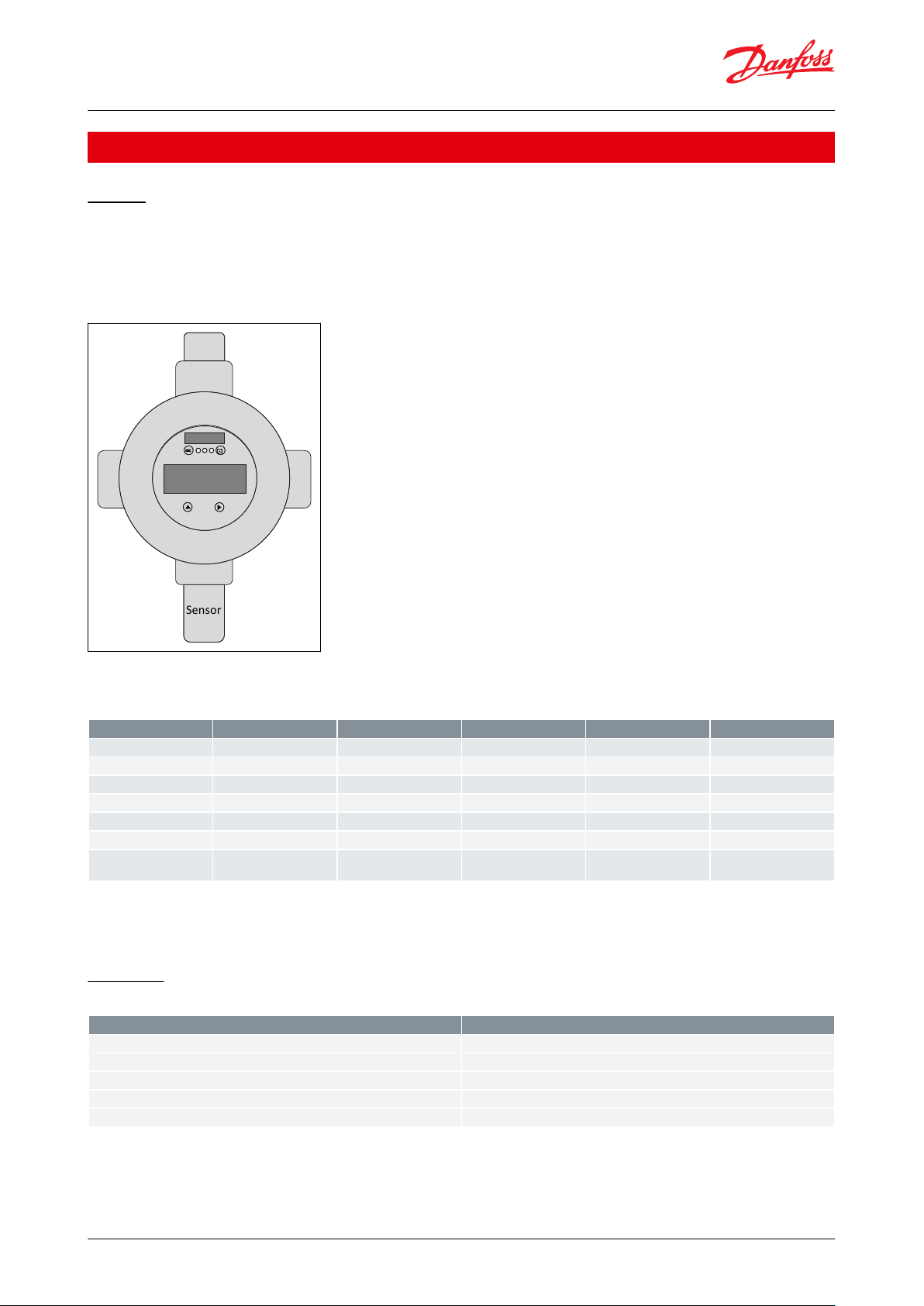
Design
General info
• Cable gland mounted
• Sensor head (SX1) mounted bottom
Figure 1: Heavy Duty
Gas types and thresholds
Table 1: Gas types and thresholds
NOTE:
Hysteresis = 5% of Alarm1 (rounded up to the next higher integer)
Alarm thresholds must be set within 10 to 90% of the sensor range.
Electrical
Table 2: Electrical
© Danfoss | Climate Solutions | 2021.11 AI272547483504en-000501 | 4
Page 5

Details
Description
Analog output signal (active)
Proportional, overload and short-circuit proof, load ≤ 500 Ω
4 – 20 mA = measuring range
3.0 < 4 mA = underrange
> 20 – 21.2 mA = overrange
2 mA = fault
> 21.8 mA = fault High
Serial interface
Serial data bus
Fault relay
Max. 30 V AC/DC, 1 A
Alarm relay
Max. 30 V AC/DC, 1 A
LCD
2 x 16 characters, 3 status LEDs, 4 menu operating elements
Details
Description
Gas type
Flammable gases
Toxic gases
HCFC, HFC, HFO
Sensor element
Pellistor
Electro Chemical
Semiconductor
Measuring range
0 – 100 % LEL
0 – 1000 ppm / 0 – 5000 ppm
0 – 10000 ppm
Response time
t90 < 20 sec. NH
3
t90 < 40 sec. for NH
3
t₉₀ > 120 sec. for NH
3
Details
Description
Material
CrNi Stahl: 1.4404
Dimensions (d x H)
30 x 56 mm (1.18 x 2.20 in.)
Protection class
Gas inlet IP64, with option splash-proof IP65
Thread
External thread M30 x 1.5
Details
Description
Humidity
15 to 90% r.H.
Operating temperature
P:
-40 °C to +60 °C / EC: -40 °C to +50 °C / SC: -40 °C to +50 °C
Details
Description
Case / colour
Aluminium pressure die-casting / light grey RAL 7032, epoxy coating
Dimensions (d x H)
95 x 82 mm
Weight
Ca. 1.3 kg
Protection class
Housing protection IP66 to IP68 (depending on the cable glands used)
Mounting
Wall mounting (sensor head downwards)
Cable entry
1 x
⁄ in. (Ansi B1.20.1)
Wire connection
Spring-type terminal, 0.08 to 2.5 mm² AWG 28 - 12
Wire length
Max. load 500 Ω (= wire resistance + controller input resistance)
ll 2G Ex db IIC T4 Gb CE 0539
Gas detection unit, Heavy duty
Sensor data
Table 3: Sensor data
Sensor head housing
Table 4: Sensor head housing
Environmental conditions
Table 5: Environmental conditions
Physical characteristics
Table 6: Physical characteristics
ATEX marking
Table 7: ATEX marking
© Danfoss | Climate Solutions | 2021.11 AI272547483504en-000501 | 5
Page 6

Details
Description
LCD
Two lines, 16 characters each, background highlighted in two colours
Operation
Menu driven via four magnetic buttons
Power consumption
5 V, 60 mA, 0.3 VA
Details
Description
Colour / Mode
Red / yellow / green (alarm – fault – operation - service)
Protection class
IP65
Gas detection unit, Heavy duty
LCD display
Table 8: LCD display Options
Status LED
Table 9: Status LED
Service and maintenance
The Heavy Duty gas detection units are calibrated either by replacing of sensor heads or by calibration with gas.
Plug & Play replacement sensors are pre-calibrated and factory certied for quick and easy calibration procedure.
The sensor is connected to the local bus via a plug connection enabling easy and simple exchange of sensor instead
of a calibration. The internal X-change routine recognizes the exchanged sensor during the exchange process and
restarts the measurement mode automatically. An LED indicates the correct procedure of the exchange operation.
To ensure the proper functioning of the units and to prevent human errors, the sensor head can only be replaced by
the same type and ppm range (exact replacement) that match the conguration. If a dierent sensor head is
installed, the GD unit will show a communication error.
As an alternative, calibration with gas can be performed via the service tool (or PC tool), calibration gas with correct
concentration and the Danfoss calibration adapter. The Danfoss gas detection units have an integrated, digital
calibration interface and procedure, which makes the calibration process easy, accurate, and time-saving. No
potentiometers or multi-meters required for the calibration. The calibration procedure requires signicantly less
calibration gas per calibration compared to traditional routines.
© Danfoss | Climate Solutions | 2021.11 AI272547483504en-000501 | 6
Page 7

1
BUS_A
GND
+24 V DC
2 +24 V DC
3
4
56BUS_B
4 - 20 mA output
7
8
9
10
11
Fault relaisene rgized in
operating mode at No alarm
- Default
Alarm relaisd e-energized in
operating mode at No alarm
- Default (Configurable)
Sensor PX2
Danfoss
148H122_11-2018
Danfoss
11L9005
1
2
3
4
5
6
7
8
9
1
0
1
1
S
er
vi
c
e
T
ool
St
a
tus
LED
A
c
k
n.
But
t
on
S
ensor
head
NPT ¾”(ANSI B1.20.1)
Internal Thread
Closed
Closed
.
NPT ¾”(ANSI B1.20.1)
Internal Thread
Sensor
1 FAILUREPOWER 2ALARM 3
D1 NH₃ PPM
0,00
2
1 3
= Ackn. button
Heavy Duty PCB
Status LEDs
Ackn.-/ Testbutton
S
er
vi
c
e
T
ool
St
a
tus
LED
A
c
k
n.
But
t
on
S
ensor
head
Sensor
Heavy Duty PCB
Status LEDs
Ackn.-/Test button
= Ackn. button
Fault relays( relay 2) energized
in operating mode at No alarm
- Default
Alarm relays( relay 1)
de-energized in operating mode
at No alarm
- Default (Configurable)
Output
Sensor PX2
BUS_A
BUS_B
Gas detection unit, Heavy duty
Electrical connection
Figure 2: Electrical connection
On board LED is similar to the display LED:
• Green (1) is power on
• Yellow (2) is an indicator of Error.
◦ when the sensor head is disconnected or not the expected type
◦ AO is activated but nothing connected
• Red (3)
◦ on alarm
On board Ackn. -/Test button:
• Test:
◦ The button must be pressed for 20 sec.
◦ Alarm is simulated, stop on release
• Ackn.:
◦ Pressed while Alarm2, the audible warning switches o and goes back on after 5 min. when the alarm situation
is still active (also possible over ESC button (use the magnetic pen).
© Danfoss | Climate Solutions | 2021.11 AI272547483504en-000501 | 7
Page 8

= Terminating resistor 560 Ohm
R
R
R
= GDU (Basic, Premium and/or Heavy Duty)
R
R
RIGHT
WRONG
Controller
unit
Controller
unit
Wire length max. 900 meter (2953 ft) per segment.
More segments with additional expansion modules max. 7200 meter (23622 ft).
Additional power limitations must be calculated.
Danfoss
11L9007
Wire length max. 900 meter (2953 ft) per segment.
More segments with additional expansion modules max. 7200 meter (23622 ft).
Additional power limitations must be calculated.
Controller
unit
Controller
unit
= Terminating resistor 560 Ohm
= GDU (Basic, Premium and/or Heavy Duty)
RIGHT
WRONG
GDU Addr. 05 GDU Addr. 04
560 R
Controller Unit
0 V DC
24 V DC
BUS_B
BUS_A
0 V DC
24 V DC
4
3
2
1
4
3
2
1
4
3
2
1
4
3
2
1
4
3
2
1
Heavy Duty GDU: U
min
=20 V DC
Other GDU: U
min
= 16 V DC
GDU Addr. 01 GDU Addr. 02 GDU Addr. 03
Danfoss
11L9006
GDU Addr. 05 GDU Addr. 04
GDU Addr. 01 GDU Addr. 02 GDU Addr. 03
Controller
unit
Gas detection unit, Heavy duty
Fieldbus loop
Each GD controller can handle up to 96 sensors and handle any mix of individual Gas detection units of the types
Basic, Premium and Heavy Duty.
The max. recommended loop wire length is 900 meter (2953 ft) per segment.
With additional segments (and additional controller expansion modules) the max recommended loop wire length is
7200 meter (23622 ft).
The controller and the last GDU in each segment must be provided with a resistor of 560 Ohm. A Umin of 16 V DC
must be secured at any spot in the loop.
Figure 3: How to make proper connections between the controller and each GDU
Figure 4: How to make proper connections between the controller and each GDU
© Danfoss | Climate Solutions | 2021.11 AI272547483504en-000501 | 8
Page 9

* Time delay set in config.
Danfoss
11L9008
Gas
Alarm1
Alarm2
LED Red
If ackn. button
not pressed
If ackn. button
pressen after
Alarm
Ackn.
Ackn.
Alarm2
Alarm1
Alarm2
Alarm1
LED Red
If ackn. button
pressed after
Alarm
If ackn. button
not pressed
Ackn.
LED
Ackn.
LED
Alarm2
Alarm1
* Time delay set in config.
Gas
Alarm1
Alarm2
Alarm1
Alarm2
Blinking (2 sec.)
Fast blinking (1 sec.)
Very fast blinking (0.1 sec.)
Power LED
Failure (e.g. sensor head is disconnected)
Slow blinking, sensor warm up
Fast blinking, sensor is in special mode (e.g. to change parameters, ...)
Gas detection unit, Heavy duty
Alarm scheme
Figure 5: Status LED
© Danfoss | Climate Solutions | 2021.11 AI272547483504en-000501 | 9
Page 10

Type
Model
Display
included
Refrigerant
Sensor
ppm (range)
Alarm ppm
Temp range
( °C)
Temp range
( °F)
Code
number
GDA
Heavy Duty
Yes
Ammonia
Electrochemical
0 – 100
25/35
-20 to +50
-4 to +122
148H6059
Heavy Duty
Yes
Ammonia
Electrochemical
0 – 300
25/150
-20 to +50
-4 to +122
148H6060
Heavy Duty
Yes
Ammonia
Electrochemical
0 – 1000
500/900
-20 to +50
-4 to +122
148H6022
Heavy Duty
Yes
Ammonia
Electrochemical
0 – 5000
1000/4500
-20 to +50
-4 to +122
148H6031
Heavy Duty
Yes
Ammonia
Semiconductor
0 – 10000
5000/9000
-20 to +50
-4 to +122
148H6035
Heavy Duty
Yes
Ammonia
Pellistor
0 – 140000 (0 –
100% LEL)
30000 (21% LEL)
-20 to +60
-4 to +140
148H6039
Heavy Duty
No
Ammonia
Electrochemical
0 – 100
25/35
-40 to +50
-40 to +122
148H6064
Heavy Duty
No
Ammonia
Electrochemical
0 – 300
25/150
-40 to +50
-40 to +122
148H6065
Heavy Duty
No
Ammonia
Electrochemical
0 – 1000
500/900
-40 to +50
-40 to +122
148H6066
Heavy Duty
No
Ammonia
Electrochemical
0 – 5000
1000/4500
-40 to +50
-40 to +122
148H6067
Heavy Duty
No
Ammonia
Semiconductor
0 – 10000
5000/9000
-40 to +50
-40 to +122
148H6068
Heavy Duty
No
Ammonia
Pellistor
0 – 140000 (0 –
100% LEL)
30000 (21% LEL)
-40 to +60
-40 to +140
148H6069
GDH
Heavy Duty
Yes
R290 (R1270,
R600A)
Pellistor
0 – 5000
800/2500
-20 to +60
-4 to +140
148H6061
Description
Code number
Replacement sensor - Heavy Duty Ammonia EC 100
148H6240
Replacement sensor - Heavy Duty Ammonia EC 300
148H6241
Replacement sensor - Heavy Duty Ammonia EC 1000
148H6217
Replacement sensor - Heavy Duty Ammonia EC 5000
148H6218
Replacement sensor - Heavy Duty Ammonia SC 10000
148H6219
Replacement sensor - Heavy Duty Ammonia P LEL
148H6220
Replacement sensor - Heavy Duty R290 / Propane P 5000
148H6242
Controller unit
148H6231
Controller solution (controller + enclosure)
148H6221
Controller solution Uptime
148H6237
Warning module (wire break monitoring module)
148H6223
Controller expansion module
148H6222
Service tool
148H6224
PC Tool
148H6235
Calibration adapter Heavy duty
148H6233
Gateway for controller
148H6228
Magnetic pen
148H6229
Gas detection unit, Heavy duty
Ordering
Table 10: Ordering
Spare parts and accessories
Table 11: Spare parts and accessories
Accessories overview
Controller unit
Used for a centralized monitoring and warning. The input signals for the controller are collected via RS485 Modbus
or analog communication. The controller can handle up to 96 digital sensors via Fieldbus and four (4) analog input.
An additional 28 analog input is possible using seven (7) expansion modules (4-20 mA signal interface). The total
number of connected sensors should not exceed 128 sensors. The controller unit can be employed as pure analog
controller, as analog/digital, or as digital controller. Conguration is menu-driven via the keypad. For fast and easy
conguration, the PC Tool is recommended.
Controller solution
Controller unit placed in an enclosure ready to be connected to a power source. A separate UPS for the controller is
available.
© Danfoss | Climate Solutions | 2021.11 AI272547483504en-000501 | 10
Page 11

Gas detection unit, Heavy duty
Warning module (wire break monitoring module)
The warning module is used for monitoring the circuiting to the warning/alarm devices on a centrally controlled gas
detection system. Wire breaks or wire interruptions in the alarm device loop will be reported to the central control.
Controller expansion module
The gas detection Controller Expansion module is used for expansion of the cable coverage in terms of number of
loops and the total wire length. Each Controller Unit can handle up to 7 Expansion modules allowing additional 7
segments with a total of 7200 meters (23622 ft.) wiring and a total of 32 relays for alarm device circuits.
Service tool
For interface with units with no display (Basic, Basic+, Premium, Premium+). Acts as a portable display and can be
connected to all Danfoss gas detection units. (Heavy Duty w. adapter).
PC tool
The PC tool is a menu-driven and standalone software used for easy addressing, parameter setting, calibration, and
data logging of the Basic, Premium and Heavy Duty gas detection units, and the controller unit.
Calibration adapter
The calibration adapter is required for connecting the calibration gas container, via the ow regulator, to the sensor
head on the gas detection units. (Two variants, One for Basic and Premium plastic head sensors; one for heavy duty
and Premium remote metal head sensors.).
Gateway for controller
The gateway is an addition to the controller and used for communicating via Modbus TCP/IP.
Magnetic pen
The pen is used to operate the Heavy Duty unit display. The Heavy Duty enclosure does not permit direct touch.
© Danfoss | Climate Solutions | 2021.11 AI272547483504en-000501 | 11
Page 12

File name
Document type
Document topic
Approval authority
DEKRA BVS 18 ATEX E 052 X
Explosive - Safety Certicate
ATEX
DEKRA IECEx BVS 18.0044X
Explosive - Safety Certicate
IECEx
500000219230.AA
Manufacturers Declaration
Similarity
Danfoss
148R6115.AA
EU Declaration
EMCD/LVD
Danfoss
Intertek 4000518
ETL
Gas detection unit, Heavy duty
Certicates, declarations, and approvals
The list contains all certicates, declarations, and approvals for this product type. Individual code number may have
some or all of these approvals, and certain local approvals may not appear on the list.
Some approvals may change over time. You can check the most current status at danfoss.com or contact your local
Danfoss representative if you have any questions.
Table 12: Valid Approvals
© Danfoss | Climate Solutions | 2021.11 AI272547483504en-000501 | 12
Page 13

Online support
Danfoss oers a wide range of support along with our products, including digital product information, software,
mobile apps, and expert guidance. See the possibilities below.
The Danfoss Product Store
The Danfoss Product Store is your one-stop shop for everything product related—no matter where
you are in the world or what area of the cooling industry you work in. Get quick access to essential
information like product specs, code numbers, technical documentation, certications, accessories,
and more.
Start browsing at store.danfoss.com.
Find technical documentation
Find the technical documentation you need to get your project up and running. Get direct access to
our ocial collection of data sheets, certicates and declarations, manuals and guides, 3D models
and drawings, case stories, brochures, and much more.
Start searching now at www.danfoss.com/en/service-and-support/documentation.
Danfoss Learning
Danfoss Learning is a free online learning platform. It features courses and materials specically
designed to help engineers, installers, service technicians, and wholesalers better understand the
products, applications, industry topics, and trends that will help you do your job better.
Create your Danfoss Learning account for free at www.danfoss.com/en/service-and-support/learning.
Get local information and support
Local Danfoss websites are the main sources for help and information about our company and
products. Find product availability, get the latest regional news, or connect with a nearby expert—all
in your own language.
Find your local Danfoss website here: www.danfoss.com/en/choose-region.
Spare Parts
Get access to the Danfoss spare parts and service kit catalog right from your smartphone. The app
contains a wide range of components for air conditioning and refrigeration applications, such as
valves, strainers, pressure switches, and sensors.
Download the Spare Parts app for free at www.danfoss.com/en/service-and-support/downloads.
Any information, including, but not limited to information on selection of product, its application or use, product design, weight, dimensions, capacity or any other
technical data in product manuals, catalogues descriptions, advertisements, etc. and whether made available in writing, orally, electronically, online or via download,
shall be considered informative, and is only binding if and to the extent, explicit reference is made in a quotation or order conrmation. Danfoss cannot accept any
responsibility for possible errors in catalogues, brochures, videos and other material. Danfoss reserves the right to alter its products without notice. This also applies to
products ordered but not delivered provided that such alterations can be made without changes to form, t or function of the product. All trademarks in this material
are property of Danfoss A/S or Danfoss group companies. Danfoss and the Danfoss logo are trademarks of Danfoss A/S. All rights reserved.
© Danfoss | Climate Solutions | 2021.11 AI272547483504en-000501 | 13
 Loading...