

Page 1
Data Sheet
Gas detection unit
Basic
Type GD Basic and Basic+
Next generation gas detection for industrial refrigeration
The Basic and Basic+ gas detection units are
used for monitoring and warning of hazardous
gas concentrations. They can be used for
detecting commonly used refrigerants.
Depending on the application, they are
available with an electrochemical or a
semiconductor sensor.
The Basic and Basic+ gas detection units are
intended to be connected to a central system
like Gas Detection Controller Unit, or a PLC, by
either Analog or RS485 open Modbus
communications. The central system converts
the alarm signal from the Basic unit to
activation of alarm devices.
The gas detection units come with a factory
default, 2-step alarm set-up ready for use. The
integrated software enables the user to
congure two individual alarm ranges. Alarm 1,
a pre-alarm indicating the gas level has passed
a predened treshold 1, and - if the gas level
passes predened treshold 2 - the nal alarm 2.
AI272545693488en-000701
Page 2

Gas detection unit, Basic
Features
• Digital, factory congured and pre-calibrated gas detectors for plug-and-play installation (no adjustment
required)
• Easy conguration via intuitive user-interface; helps simplify operator handling and minimize risk of operational,
settings and calibration errors
• Flexible connection - by either Analog or RS485 open Modbus communications
• Fieldbus wiring - connect and power up to 96 sensors, wire length max. 900 meter per segment; expansion
modules permits additional segments
• Automatic self-diagnostics to ensure correct communication and operation
• Sensor seal cap to prevent premature exposure during installation
• Digital user interface ensures higher sensor accuracy
• Reduced risk of false alarms due to temperature compensated sensors
• Password protected alarm settings allowing authorized access only
• LED status signals and alarms
• Buzzer & Light option for local audio and visual alarms (Basic+)
• On-board acknowledge button to reset alarms and to verify the that no gas leaks are present
• Service alerts on unit, controller or both, readable via service tool Display
• Quick and precise calibration procedures - either by Plug & Play replacement sensors or calibration with gas. No
potentiometers or multi-meters required
• For improved safety and to optimize the lifetime of the sensor, degenerated sensors with too low sensitivity
(<30%) are rejected during calibration process
• Conformity to EN 50271, EN 61010-1, ANSI/UL 61010 1, CAN/CSA-C22.2 No. 61010-1
• Enables regulatory compliance with EN 378:2016, ISO 5149:2014, IIAR 2-2017, and ASHRAE 15:2016
© Danfoss | Climate Solutions | 2021.11 AI272545693488en-000701 | 2
Page 3

Gas detection unit, Basic
Functions
Working principle/Operation
One sensor can be connected to the Basic/Basic+ sensor board via local bus. The Sensor board provides the power
supply of the sensor and prepares the measured data for digital communication.
The operation menu of the Basic/Basic+ software is accessed through the connected Gas Detection Controller or via
the dedicated GD Service tool (or PC tool). The Service tool (or PC tool) is plugged directly to the board of the unit.
The interfaces allow the unit conguration, setting of the unit alarm levels and calibration of the attached sensor.
The service tool (or PC tool) can be used on all units across the Basic, Premium and Heavy Duty platforms.
The alarm signals can be handled by the Gas Detection Controller (or a PLC) via the 4 – 20 mA (2 – 10V) analog
output or the RS485 open Modbus communication. For additional operational safety the changing of parameters is
password protected allowing authorized access only. The factory default password can easily be customized.
© Danfoss | Climate Solutions | 2021.11 AI272545693488en-000701 | 3
Page 4
Basic Basic +
Danfoss
148H132_01-2018
Sensor Sensor
Sensor
Sensor Type
ppm range
Alarm 1
Alarm 2
Hysteresis
Ammonia EC 100
Electrochemical
0 – 100 ppm
25 ppm
35 ppm
2 ppm
Ammonia EC 300
Electrochemical
0 – 300 ppm
25 ppm
150 ppm
2 ppm
Ammonia EC 1000
Electrochemical
0 – 1000 ppm
500 ppm
900 ppm
25 ppm
Ammonia SC 1000
Semiconductor
0 – 1000 ppm
500 ppm
900 ppm
25 ppm
HF R1234yf SC 2000 (FR3)
Semiconductor
0 - 2000 ppm
500 ppm
900 ppm
25 ppm
HFC R134A SC 2000 (FR7)
Semiconductor
0 - 2000 ppm
500 ppm
900 ppm
25 ppm
HFC R404A, R507 SC2000
Semiconductor
0 – 2000 ppm
500 ppm
900 ppm
25 ppm
Ammonia SC 10000
Semiconductor
0 – 10000 ppm
5000 ppm
9000 ppm
250 ppm
Ammonia P LEL
Pellistor
0 – 100% LEL
(0 – 140000)
21% LEL
(30000 ppm)
21% LEL
(30000 ppm)
1%
CO2 IR 20000 (2% Vol.)
Infrared
(0 – 2% Vol)
(0 – 20000 ppm
0.5% Vol
(5000 ppm)
0.9% Vol
(9000 ppm)
0.025% vol
(250 ppm)
Details
Description
Power supply
19 – 29 V AC/DC, DC reverse-polarity protected (selected units 100 – 240V AC)
Power consumption (24 V DC)
Max. 250 mA (6 VA)
Gas detection unit, Basic
Product specication
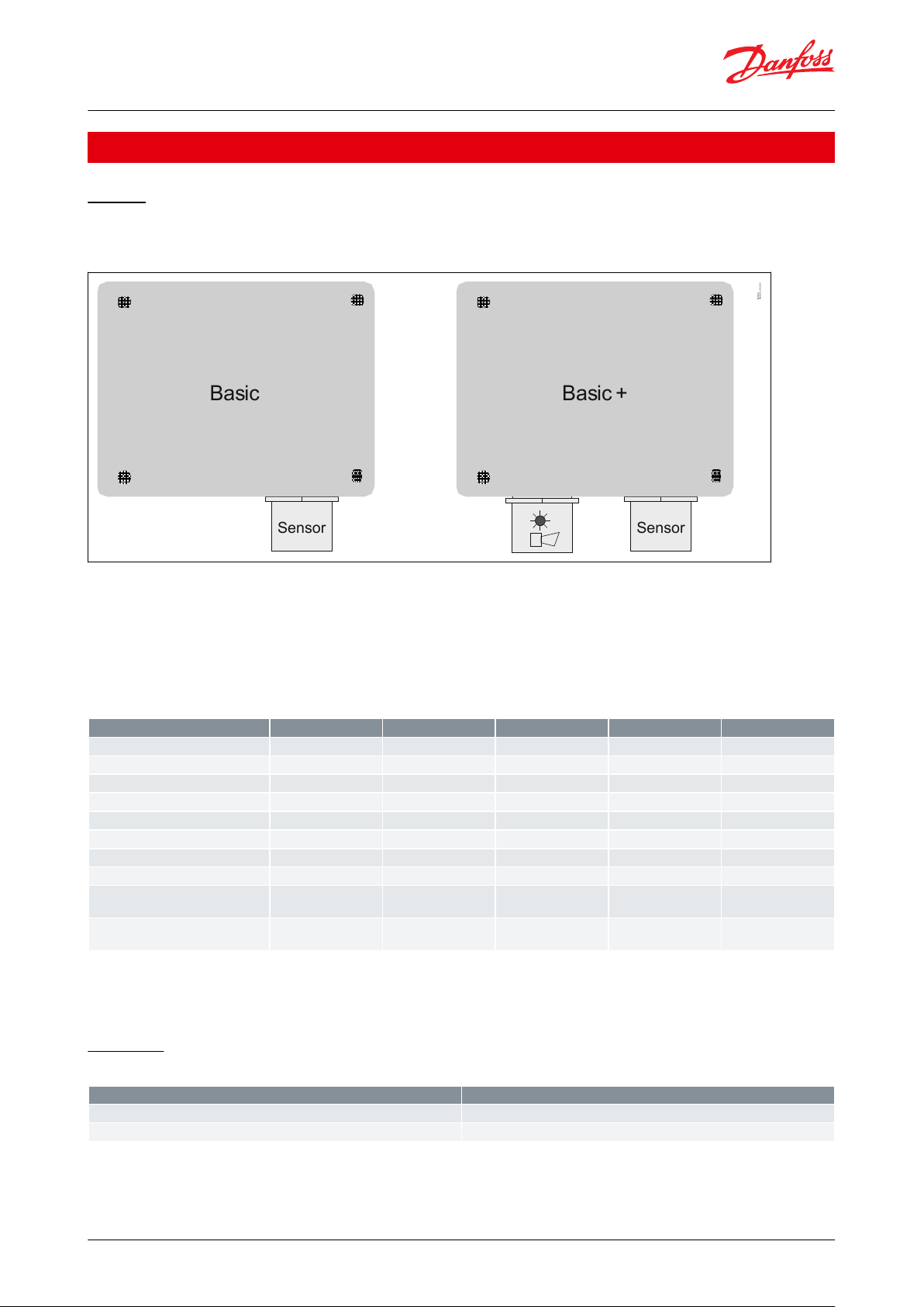
Design
General information
Figure 1: GD Basic and Basic+
• Cable gland not mounted but enclosed
• 4 mounting ears included
• Sensor head mounted bottom right
• Alarm device (Buzzer & Light) mounted bottom left (only Basic +)
Gas types and thresholds
Table 1: Gas types and thresholds
NOTE:
Hysteresis = 5% of Alarm1 (rounded up to the next higher integer)
LEL/LFL = Lower explosive limit / Lower ammability limit
Electrical
Table 2: Electrical
© Danfoss | Climate Solutions | 2021.11 AI272545693488en-000701 | 4
Page 5

Details
Description
Power supply
5 V DC, 250 mA max., overload, short-circuit and reverse-polarity protected
Details
Description
Local bus
1-wire / 19200 baud
Fieldbus
RS 485 / 19200 baud
Tool bus
2-wire / 19200 baud
Details
Description
Temperature range
-40 °C to +50 °C (-40 °F to 122 °F)
Humidity range
15 – 90 % RH not-condensing
Storage temperature
+5 °C to +30 °C (41 °F to 86 °F)
Storage time
12 months
Details
Description
Housing
Type A
Material
Polycarbonate
Burning behaviour
UL 94 V2
Housing colour
Black
Dimensions (W x H x D in mm)
94 x 130 x 57
Weight (kg)
Approx. 0.3kg (0.8 lbs.)
Protection class
IP65
Installation
Wall mounting
Cable entry
2 x M12 / 3 x M20
Wire connection:
Power supply, eldbus
Screw-type terminals 0.25 to 2.5 mm
2
(25 AWG to 14 AWG)
Analog output
Screw-type terminals 0.25 to 1.3 mm
2
(25 AWG to 17 AWG)
Local bus for sensor
3-pin plug connector
Cable lengths local bus for remote sensor board
Max. 5 m (16.4 ft.)
Description
Proportional, overload and short-circuit proof, load ≤ 500 Ohm
4 – 20 mA = measuring range
3.0 < 4 mA = underrange
> 20 – 21.2 mA = overrange
2.0 mA = fault
(congurable)
Details
Description
Colour
3 color light: Green, yellow, red
Acoustic pressure
> 85 dB (A) (0.1 m distance)
Frequency
2300 Hz
Protection class
IP65
Gas detection unit, Basic
Outgoing line local bus
Table 3: Outgoing line local bus
Serial interface
Table 4: Serial interface
General
Table 5: General
Physical
Table 6: Physical
Analog output signal
Table 7: Analog output signal
Status LED / Buzzer & light (only Basic+)
Table 8: Status LED / Buzzer & light (only Basic+)
© Danfoss | Climate Solutions | 2021.11 AI272545693488en-000701 | 5
Page 6

1 2 4
Bus_B
Bus_A
0 V AC/DC
24 V AC/DC
Ackn. -/Test
button T1
X4
3
4
X8
X2
5
X9
Service Tool
Buzzer &
3-light alarm
X1
Analog Output
Status LED
Green/Yellow/Red
GND
JP5*
Open: 4-20mA
Closed: 2-10V AO_01
Jumper
J1
J2
J3
Sensor
Danfoss
148H119_11-2018
Analog Output
Sensor
Ackn.-/Test
button T1
Open: 4 – 20mA
Closed: 2 – 10V
Status LED
Green/Yellow/Red
Jumper
Bus_B
Bus_A
X9
Service Tool
Buzzer &
3-light alarm
Gas detection unit, Basic
Electrical connection
Figure 2: Electrical connection
Status LED:
• GREEN is power on
◦ ashing if maintenance needed
• YELLOW is an indicator of Error
◦ when the sensor head is disconnected or not the expected type
◦ AO is activated but nothing connected
◦ ashing when sensor is in special mode (e.g. when changing parameters)
• RED on alarm, similar to the buzzer & light alarm
Ackn. -/Test button:
• TEST:
◦ The button must be pressed for 20 sec
◦ Alarm1 and Alarm2 is simulated, stop on release
• ACKN:
◦ Pressed while Alarm2, the audible warning switches o and goes back on after 5 min. when the alarm situation
is still active
* JP5 open → AO 4 – 20 mA (Default)
* JP5 closed → AO 2 – 10 Volt
NOTE:
A resistor comes installed on the analog output connections – if analog output is used, remove the resistor.
Fieldbus loop
Each GD controller can handle up to 96 sensors and handle any mix of individual Gas detection units of the types
Basic, Premium and Heavy Duty.
The max. recommended loop wire length is 900 meter (2953 ft) per segment.
© Danfoss | Climate Solutions | 2021.11 AI272545693488en-000701 | 6
Page 7

= Terminating resistor 560 OhmR
R
R
= GDU (Basic, Premium and/or Heavy Duty)
R
R
RIGHT
WRONG
Controller
unit
Controller
unit
Wire length max. 900 meter (2953 ft) per segment.
More segments with additional expansion modules max. 7200 meter (23622 ft).
Additional power limitations must be calculated.
Danfoss
148H123
GDU Addr. 05 GDU Addr. 04
560 R
Controller Unit
0 V DC
24 V DC
BUS_B
BUS_A
0 V DC
24 V DC
4
3
2
1
4
3
2
1
4
3
2
1
4
3
2
1
4
3
2
1
U
min
= 16 V DC
GDU Addr. 01 GDU Addr. 02 GDU Addr. 03
Danfoss
148H139_01-2018
GDU Addr. 05 GDU Addr. 04
GDU Addr. 01 GDU Addr. 02 GDU Addr. 03
Controller
unit
Gas detection unit, Basic
With additional segments (and additional controller expansion modules) the max recommended loop wire length is
7200 meter (23622 ft).
The controller and the last GDU in each segment must be provided with a resistor of 560 Ohm. A Umin of 16 V DC
must be secured at any spot in the loop.
Figure 3: How to make proper connections between the controller and each GDU
Figure 4: How to make proper connections between the controller and each GDU
© Danfoss | Climate Solutions | 2021.11 AI272545693488en-000701 | 7
Page 8

Time
delay*
Buzzer &
3-light alarm
* Time delay set in config.
Gas
Alarm1
Alarm2
LED
If ackn. button
not pressed
LED
If ackn. button
pressed during
Alarm2
Ackn.
Buzzer
Buzzer
LED
If ackn. button
pressed after
Alarm
Buzzer
Ackn.
Ackn.
Alarm2
Alarm1
WAO
Housing
Sensor
Danfoss
148H158_03-2018
Alarm1
Alarm2
Housing
Sensor
Buzzer &
3-light alarm
Alarm1
Alarm2
Ackn.
Buzzer
LED
Ackn.
Buzzer
LED
Ackn.
Buzzer
LED
Alarm2
Alarm1
* Time delay set in config.
Alarm2
Alarm1
Time
delay*
If ackn. button
pressed after
Alarm
If ackn. button
pressed during
Alarm2
If ackn. button
not pressed
Blinking (2 sec.)
Fast blinking (1 sec.)
Very fast blinking (0.1 sec.)
Buzzer on
Static, Power LED
Gas detection unit, Basic
Alarm scheme
Figure 5: Alarm scheme
Buzzer & light
© Danfoss | Climate Solutions | 2021.11 AI272545693488en-000701 | 8
Page 9

Gas detection unit, Basic
Service and maintenance
The Basic/Basic+ gas detection units are calibrated either by replacing of sensor heads or by calibration with gas.
Plug & Play replacement sensors are pre-calibrated and factory certied for quick and easy calibration procedure.
The sensor is connected to the local bus via a plug connection enabling easy and simple exchange of sensor instead
of an on-site calibration. The internal X-change routine recognizes the exchanged sensor during the exchange
process and restarts the measurement mode automatically. An LED indicates the correct procedure of the exchange
operation. To ensure the proper functioning of the units and to prevent human errors, the sensor head can only be
replaced by the same type and ppm range (exact replacement) that match the conguration. If a dierent sensor
head is installed, the GD unit will show a communication error.
As an alternative, calibration with gas can be performed via the service tool (or PC tool), calibration gas with correct
concentration and the Danfoss calibration adapter. The Danfoss gas detection units have an integrated, digital
calibration interface and procedure, which makes the calibration process easy, accurate, and time-saving. No
potentiometers or multi-meters required for the calibration. The calibration procedure requires signicantly less
calibration gas per calibration compared to traditional routines.
© Danfoss | Climate Solutions | 2021.11 AI272545693488en-000701 | 9
Page 10

Type
Model
Refrigerant
Sensor
ppm range
Alarm ppm
Temp. Range
[°C]
Temp. Range
[°F]
Code number
GDA
Basic
Ammonia
Electrochemical
0 – 100
25/35
-40 to +50
-40 to +122
148H6000
Basic+
(1)
Ammonia
Electrochemical
0 – 100
25/35
-40 to +50
-40 to +122
148H6001
Basic
Ammonia
Electrochemical
0 – 300
25/150
-40 to +50
-40 to +122
148H6008
Basic+
(1)
Ammonia
Electrochemical
0 – 300
25/150
-40 to +50
-40 to +122
148H6009
Basic
Ammonia
Electrochemical
0 – 1000
500/900
-40 to +50
-40 to +122
148H6014
Basic+
(1)
Ammonia
Electrochemical
0 – 1000
500/900
-40 to +50
-40 to +122
148H6015
Basic
Ammonia
Semiconductor
0 – 1000
500/900
-40 to +50
-40 to +122
148H6023
Basic+
(1)
Ammonia
Semiconductor
0 – 1000
500/900
-40 to +50
-40 to +122
148H6024
Basic
Ammonia
Semiconductor
0 – 10000
5000/9000
-40 to +50
-40 to +122
148H6071
Basic Remote
Ammonia
Semiconductor
0 – 10000
5000/9000
-40 to +50
-40 to +122
148H6073
Basic
Ammonia
Pellistor
0 – 140000
30000
-40 to +50
-40 to +122
148H6070
GDHF
Basic + AC ( 100
– 240V AC)
R404a, R507a,
R32, R125,
R407c, R434a,
R488a,R410a,
R452b,R143b
Semiconductor
0 – 2000
500/900
-30 to +50
-22 to +122
148H6056
Basic + AC ( 100
– 240V AC)
R134a, R407a,
R416a, R417a,
R422a, R422d,
R427a, R437a,
R438a, R449a,
R407f, R450a
Semiconductor
0 – 2000
500/900
-30 to +50
-22 to +122
148H6057
Basic + AC ( 100
– 240V AC)
R1234yf, R452a,
R513a, R454c,
R455a, R454b,
R1234ze
Semiconductor
0 – 2000
500/900
-30 to +50
-22 to +122
148H6058
GDHF
Basic
R404a, R507a,
R32, R125,
R407c, R434a,
R488a, R410a
Semiconductor
0 – 2000
500/900
-40 to +50
-40 to 122
148H6045
Basic+
(1)
R404a, R507a,
R32, R125,
R407c, R434a,
R488a, R410a
Semiconductor
0 – 2000
500/900
-40 to +50
-40 to 122
148H6046
GDC
Basic
CO
2
Infrared
0 – 20000
5000/9000
-40 to +50
-40 to 122
148H6072
Description
Code number
Replacement sensor - Ammonia EC 100
148H6200
Replacement sensor - Ammonia EC 300
148H6201
Replacement sensor - Ammonia EC 1000
148H6202
Replacement sensor - Ammonia SC 1000
148H6203
Replacement sensor - HFC R404A, R507 SC 2000
148H6210
Replacement sensor - HFC R1234yf SC 2000
148H6239
Replacement sensor - HFC R134a SC 2000
148H6211
Controller unit
148H6231
Controller solution (controller + enclosure)
148H6221
Controller expansion module
148H6222
Service tool
148H6224
PC tool
148H6235
Calibration adapter
148H6232
Buzzer & light - acoustic buzzer and optic led
148H6225
Air duct set
148H6236
Seal cap
148H6227
Gas detection unit, Basic
Ordering
Table 9: Ordering
(1)
(1)
incl buzzer & Light
incl buzzer & Light
Spare parts and accessories
Table 10: Spare parts and accessories
© Danfoss | Climate Solutions | 2021.11 AI272545693488en-000701 | 10
Page 11

Description
Code number
Splash guard
148H6226
Gateway for controller
148H6228
Remote kit
148H6238
Gas detection unit, Basic
Accessories overview
Controller unit
Used for a centralized monitoring and warning. The input signals for the controller are collected via RS485 Modbus
or analog communication. The controller can handle up to 96 digital sensors via Fieldbus and four (4) analog input.
An additional 28 analog input is possible using seven (7) expansion modules (4 – 20 mA signal interface). The total
number of connected sensors should not exceed 128 sensors. The controller unit can be employed as pure analog
controller, as analog/digital, or as digital controller. Conguration is menu-driven via the keypad. For fast and easy
conguration, the PC Tool is recommended.
Controller solution
Controller unit placed in an enclosure ready to be connected to a power source. A separate UPS for the controller is
available.
Controller expansion module
The gas detection Controller Expansion module is used for expansion of the cable coverage in terms of number of
loops and the total wire length. Each Controller Unit can handle up to 7 Expansion modules allowing additional 7
segments with a total of 7200 meters (23622 ft.) wiring and a total of 32 relays for alarm device circuits.
Service tool
For interface with units with no display (Basic, Basic+, Premium, Premium+). Acts as a portable display and can be
connected to all Danfoss gas detection units. (Heavy Duty w. adapter).
PC tool
The PC tool is a menu-driven and standalone software used for easy addressing, parameter setting, calibration, and
data logging of the Basic, Premium and Heavy Duty gas detection units, and the controller unit.
Calibration adapter
The calibration adapter is required for connecting the calibration gas container, via the ow regulator, to the sensor
head on the gas detection units. (Two variants, One for Basic and Premium plastic head sensors; one for heavy duty
and Premium remote metal head sensors.).
Buzzer & light - acoustic buzzer and optic led
Can be installed in Basic or Premium units providing a local alarm.
Air duct set
The air duct set is specially designed to capture the airow in air ducts. It can be connected to the standard sensor
heads, except from Heavy Duty gas detection units.
Seal cap
Airtight seal cap to protect the sensor head against premature exposure during installation. The seal cap is mounted
on new sensors (complete units and replacement sensors) but is also available as an accessory.
Splash guard
To protect the sensor head against water exposure during wash-down cleaning and rinsing operations.
Gateway for controller
The gateway is an addition to the controller and used for communicating via Modbus TCP/IP.
Remote kit
Enabling installation of a sensor head in plastic housing 5m (16.4 ft.) from the unit. This means that the gas
detection unit can be placed outside the room where the sensor is placed to detect hazardous gases, allowing
reading of and interfacing with the unit without entering the dedicated space. Basic and Premium gas detection
units.
© Danfoss | Climate Solutions | 2021.11 AI272545693488en-000701 | 11
Page 12

Type
File name
Document type
Document topic
Approval authority
GDA
148R6115.AA
EU Declaration
EMCD/LVD
Danfoss
EMC directives 2014/30/EU
Conformity to EN 50271, EN 61010-1
ETL listed to UL 61010-1 and CSA C22.2 No.61010-1
Enables regulatory compliance with EN 378:2016, ISO 5149:2014, IIAR 2-2017, and ASHRAE 15:2016
Gas detection unit, Basic
Certicates, declarations, and approvals
The list contains all certicates, declarations, and approvals for this product type. Individual code number may have
some or all of these approvals, and certain local approvals may not appear on the list.
Some approvals may change over time. You can check the most current status at danfoss.com or contact your local
Danfoss representative if you have any questions.
Table 11: Valid Approvals
Table 12: Compliance
© Danfoss | Climate Solutions | 2021.11 AI272545693488en-000701 | 12
Page 13

Online support
Danfoss oers a wide range of support along with our products, including digital product information, software,
mobile apps, and expert guidance. See the possibilities below.
The Danfoss Product Store
The Danfoss Product Store is your one-stop shop for everything product related—no matter where
you are in the world or what area of the cooling industry you work in. Get quick access to essential
information like product specs, code numbers, technical documentation, certications, accessories,
and more.
Start browsing at store.danfoss.com.
Find technical documentation
Find the technical documentation you need to get your project up and running. Get direct access to
our ocial collection of data sheets, certicates and declarations, manuals and guides, 3D models
and drawings, case stories, brochures, and much more.
Start searching now at www.danfoss.com/en/service-and-support/documentation.
Danfoss Learning
Danfoss Learning is a free online learning platform. It features courses and materials specically
designed to help engineers, installers, service technicians, and wholesalers better understand the
products, applications, industry topics, and trends that will help you do your job better.
Create your Danfoss Learning account for free at www.danfoss.com/en/service-and-support/learning.
Get local information and support
Local Danfoss websites are the main sources for help and information about our company and
products. Find product availability, get the latest regional news, or connect with a nearby expert—all
in your own language.
Find your local Danfoss website here: www.danfoss.com/en/choose-region.
Spare Parts
Get access to the Danfoss spare parts and service kit catalog right from your smartphone. The app
contains a wide range of components for air conditioning and refrigeration applications, such as
valves, strainers, pressure switches, and sensors.
Download the Spare Parts app for free at www.danfoss.com/en/service-and-support/downloads.
Any information, including, but not limited to information on selection of product, its application or use, product design, weight, dimensions, capacity or any other
technical data in product manuals, catalogues descriptions, advertisements, etc. and whether made available in writing, orally, electronically, online or via download,
shall be considered informative, and is only binding if and to the extent, explicit reference is made in a quotation or order conrmation. Danfoss cannot accept any
responsibility for possible errors in catalogues, brochures, videos and other material. Danfoss reserves the right to alter its products without notice. This also applies to
products ordered but not delivered provided that such alterations can be made without changes to form, t or function of the product. All trademarks in this material
are property of Danfoss A/S or Danfoss group companies. Danfoss and the Danfoss logo are trademarks of Danfoss A/S. All rights reserved.
© Danfoss | Climate Solutions | 2021.11 AI272545693488en-000701 | 13
 Loading...