

Danfoss GDA SC 10000, GDA EC 300, GDA SC 1000, GDA EC 1000, GDC IR 10000 Installation Manual
...Page 1
Installation Guide
Making Bump test on Danfoss gas detecting sensors,
types GDA and GDC
148 R95 44
148 R95 44
4 DKRCI.PI.S00.B2.02 / 520H2572 © Danfoss A/S (MWA), 2015-02 © Danfoss A/S (MWA), 2015-02 DKRCI.PI.S00.B2.02 / 520H2572 1
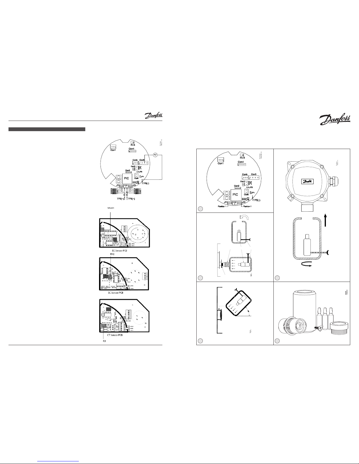
Beaker
EC/SC/CTAdaptor
Ampoules
M35
Adaptor
BUMP TEST equipment
EC/SC/CT-Adaptor Ampoule Breaker
Sensor PCB
Gas ows through
the back and
front of the
sensor head
Bump test on a wall mounted CO2 detector
1
2
3
4
5
ENGLISH
Appendix 1
Checking the zero. (0.0 V output)
EC sensor
To adjust the zero, Pot VR201 must be operated. It is located on the
Sensor PCB
Connect a voltmeter to TP0 on the mother PCB and Con3, pin 3 on
the mother PCB
Pot VR201 (on the Sensor PCB) is used to adjust the zero of the
range (span). Measure the Voltage output between TP0 (negative)
and Con3 pin 3 (positive) at the 0V signal and adjust the Pot to 0.0
V or slightly positive (0.01 V is acceptable).
SC sensor
To adjust the zero, Pot RV2 must be operated. It is located on the
Sensor PCB.
Connect a voltmeter to TP0 on the mother PCB and Con3, pin 3 on
the mother PCB (see g. A1)
Pot RV2 (on the Sensor PCB) is used to adjust the zero of the range
(span). Measure the Voltage output between TP0 (negative) and
Con3 pin 3 (positive) at the 0V signal and adjust the Pot to 0.0 V or
slightly positive (0.01 V is acceptable).
CT sensor
To adjust the zero, Pot R3 must be operated. It is located on the
Sensor PCB.
Connect a voltmeter to TP0 on the mother PCB and Con3, pin 3 on
the mother PCB (see g. A1).
Pot R3 (on the Sensor PCB) is used to adjust the zero of the range
(span). Measure the Voltage output between TP0 (negative) and
Con3 pin 3 (positive) at the 0V signal and adjust the Pot to 0.0
V or slightly positive (0.01 V is acceptable).
Page 2
© Danfoss A/S (MWA), 2015-02 DKRCI.PI.S00.B2.02 / 520H2572 32 DKRCI.PI.S00.B2.02 / 520H2572 © Danfoss A/S (MWA), 2015-02
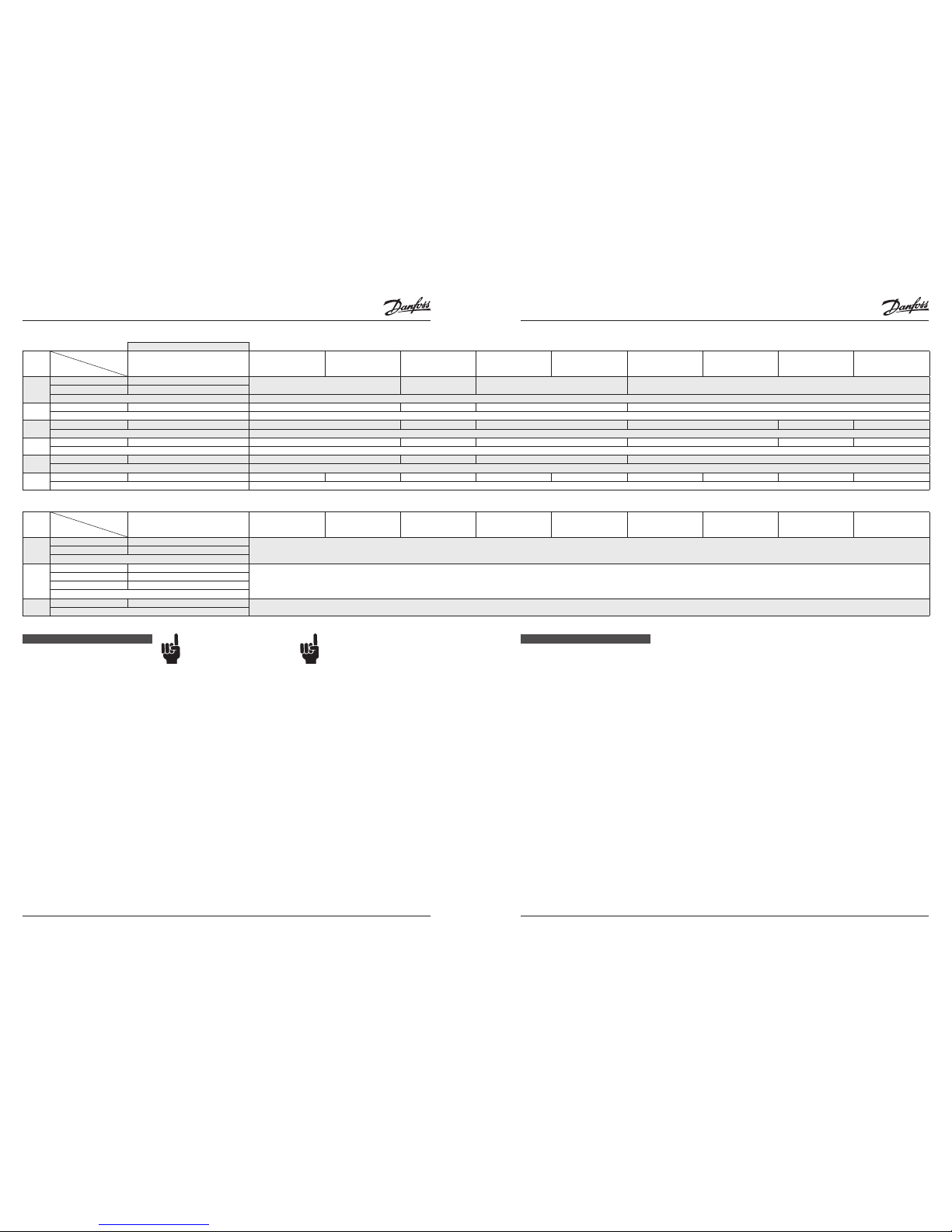
Table 1 - Bump Test
Pass test criteria
Models
Sensor
Requirement for sensor response to pass Bump
Test. Measure Voltage Output on Con3,(mother
PCB)
pin 1 and 3
Standard Basic Standard Basic with
LCD display
IP 65 for High RH and
Fast response
IP 56 enclosure IP 56 enclosure
Low Temperature
EExd model EExd model
Low Temperature
IP 66 enclosure 5 m remote
IP 65 sensor
IP 66 enclosure 5 m remote
IP 65 EExd sensor
1
GDA EC 100 >= 5 .0 V
Beaker + EC/SC/CT-Adaptor Beaker Beaker + EC/SC/CT-Adaptor Beaker
GDA EC 300 >= 1.67 V
Bump test method 100 ppm Ammonia Ampoule
2
GDA EC 1000 >= 5 V Beaker + EC/SC/CT-Adaptor Beaker Beaker + EC/SC/CT-Adaptor Beaker
Bump test method 1000 ppm Ammonia Ampoule
3
GDA SC 1000 >= 5 .0 V Beaker + EC/SC/CT-Adaptor Beaker Beaker + EC/SC/CT-Adaptor Beaker + M35 Adaptor Beaker Beaker + M35 Adaptor
Bump test method 1000 ppm Ammonia Ampoule
4
GDA SC 10000 >= 0.5 V Beaker + EC/SC/CT-Adaptor Beaker Beaker + EC/SC/CT-Adaptor Beaker + M35 Adaptor Beaker Beaker + M35 Adaptor
Bump test method 1000 ppm Ammonia Ampoule
5
GDA CT 30000 >= 5 .0 V Beaker + EC/SC/CT-Adaptor Beaker + M35 Adaptor Beaker + EC/SC/CT-Adaptor Beaker + M35 Adaptor
Bump test method App. 5-8 % Ammonia water in a cloth
1
)
6
GDC IR 10000 >= 1.0 V Beaker Beaker not available Beaker Beaker Beaker Beaker not available not available
Bump test method 2000 ppm CO
2
Ampoule
1
) Drop a cloth to the bottom of the beaker, hold it at the bottom with the screw. Moisten the cloth (5-10 drops) with 5-8 % ammonia water.
Restricted bump test
Models
Sensor
Requirement for sensor response to pass Bump
Test. Measure Voltage Output on Con3,(mother
PCB)
pin 1 and 3
Standard Basic Standard Basic with
LCD display
IP 65 for High RH and
Fast response
IP 56 enclosure IP 56 enclosure
Low Temperature
EExd model EExd model
Low Temperature
IP 66 enclosure 5 m remote
IP 65 sensor
IP 66 enclosure 5 m remote
IP 65 EExd sensor
7
GDC IR 20000 >= 2 .0 V
Sensor is self calibrating. Breathe on sensor to see responseGDC IR 40000 >= 2 .0 V
Bump test method
8
GDHC SC 1000 >= 5 V
Long life sensor. Use a cigarette lighter to see response
GDHF SC 1000 >= 5 V
GDHF-R3 SC 1000 >= 5 V
Bump test method
9
GDH SC 5000 >= 5 .0 V
Long life sensor. Use a cigarette lighter to see response
Bump test method
ENGLISH
Introduction
The frequency of testing or calibration is
generally determined by local regulation or
standards.
There are two concepts that need to be
dierentiated: bump test and calibration
Bump Test: This consists of exposing
the sensor to a gas. The objective is to
establish if the sensor is reacting to the
gas and all the sensor outputs are working
correctly. A qualied bump test is a test
carried out using ampoules or cylinders of
known concentration.
Calibration: This consists of exposing the
sensor to a calibration gas setting the “zero”
or “Standby voltage”, the span or range,
and checking/adjusting all the outputs, so
that they are activated at a specied gas
concentration.
Danfoss recommends annual
checks by qualied bump test
and replacement of the sensor
PCB with a Danfoss pre-calibrated
certied sensor PCB every two
years. The mother PCB is at the
same time tested with the GD
tester.
The alternative to this is a full
on site calibration. Sensor
replacement should be more cost
eective, eliminates end of life
concerns, and constantly renews
the detection system.
Procedures for bump test and calibration
vary depending on the sensor technology
used and the gas in question.
The GD is available in four sensor versions:
Semiconductor (SC), Electrochemical (EC),
Catalytic (CT), and Infrared (IR) for CO
2
.
Before you carry out the test or
calibration:
1. Advise occupants, plant
operators, and supervisors.
2. Check if the relays (Con6 and
Con7) are connected
to external systems such as
sprinkler systems, plant
shut down, external sirens and
beacons, ventilation, etc. and
disconnect as appropriate.
3. Deactivate alarm delays with
JP1 and JP2. See g. 1.
For this the GD must be
powered o.
4. For Bump Test the GD should
be powered up overnight.
NOTE:
If unit has been installed and running
for about 24 hrs, and you need to power
it o to set the delay at 0 min, then the
warm-up is 2 min and you can begin the
testing or calibration.
ENGLISH
Bump test (every year)
Ideally bump tests are conducted on site in
a clean air atmosphere.
The bump test can be carried out on
following types of GD
(see table 1)
GDA (qualied bump test)
GDC (qualied bump test/ restricted
bump test)
GDHC (restricted bump test)
GDHF (restricted bump test)
GDHF-R3 (restricted bump test)
See table 1, to nd the GD type and the
corresponding Bump test method.
Checking the zero (0 Voltage output).
See Appendix 1. (not required for IR sensor)
1. Remove the cover of enclosure of the
GD
2. Make sure that both the ampoules and
the calibration beaker are clean and dry
(see g. 5).
3. Unscrew the beaker hold screw and
place the ampoule so that is sits in the
base of the beaker (see g. 2).
4. Tighten on the screw ampoule without
breaking it.
5. For the models:
Standard Basic
Standard Basic with LCD display
IP 56 enclosure
IP 56 enclosure Low Temperature
Screw in:
EC/SC/CT-Adaptor or M35-Adaptor into
the Beaker according to table 1.
Place the beaker with the EC/SC/CT Adaptor over the sensor.
It should be as tight tting as possible
to allow maximum exposure to the gas
(see g. 5).
For the GDC (CO2)models:
Standard Basic
Standard Basic with LCD display
IP 56 enclosure
IP 56 enclosure Low Temperature
Place the beaker over the sensor in a
45° degree (see g. 3). This allows gas to
ow through the back of the sensor
and through the calibration ports.
For the models:
IP 65 for High RH and Fast response
EExd model
EExd model Low Temperature
IP 66 enclosure 5 m remote IP 65 sensor
IP 66 enclosure 5 m remote IP 65 EExd
sensor
Screw/t the beaker (possibly with
M35 Adaptor) on the remote
sensorhead (see g. 4). It should be as
tight tting as possible to allow
maximum exposure to the gas.
6. Connect volt meter to monitor sensor
response.
(Con3 pin 1 and 3 - see g. 1).
7. Tighten on the ampoule until it
shatters allowing the content to diuse
in the beaker. It should be left in place
for approximately 5 min.
8. Voltage output will increase. This
conrms that the sensor is responding.
See Pass test criteria in table 1.
9. Carefully remove any ampoule remains
from the gas detector, and reassemble
the sensor enclosure.
Fill out the GD Bump Test Certicate.
 Loading...