

Page 1
Instructions
Upgrade of sensor in GD gas detecting sensors: IP 56 / IP 56 Low. temp.
with sensor type Infrared for CO
This sensor upgrade procedure replaces the internal sensor with an external sensor on Danfoss GD gas detecting sensors:
IP 56 enclosure and IP 56 enclosure Low Temperature.
148R9555
The procedure applies to the following Danfoss code numbers:
148H5072, 148H5082,148H5092: IP 56, without heater built-in
148H5075,148H5085: IP 56 Low Temperature, with heater built-in.
Step Description
1. Note that the sensor upgrade procedure is intended to be performed by a technically qualied person who is also familiar
with electronics, ESD eects, and related safety precautions.
2. When the actual Danfoss GD gas detecting sensor is located, gather the following components:
• Upgrade kit (GD Tester PCB, new sensor, sensor daughter PCB, nylon stando, and instructions)
• Crosshead screwdriver
• 4 mm Hex driver
3. IMPORTANT:
The device MUST BE powered o before replacing the sensor.
Remove power from the unit by shutting o power at the source.
4. ESD SENSITIVE COMPONENTS:
Follow proper electrostatic discharge (ESD) precautions. Touch a grounded metal object (e.g., conduit)
prior to working on the device in order to dissipate any built-up static and to reduce the risk of ESD
damage to components.
2
148R9555
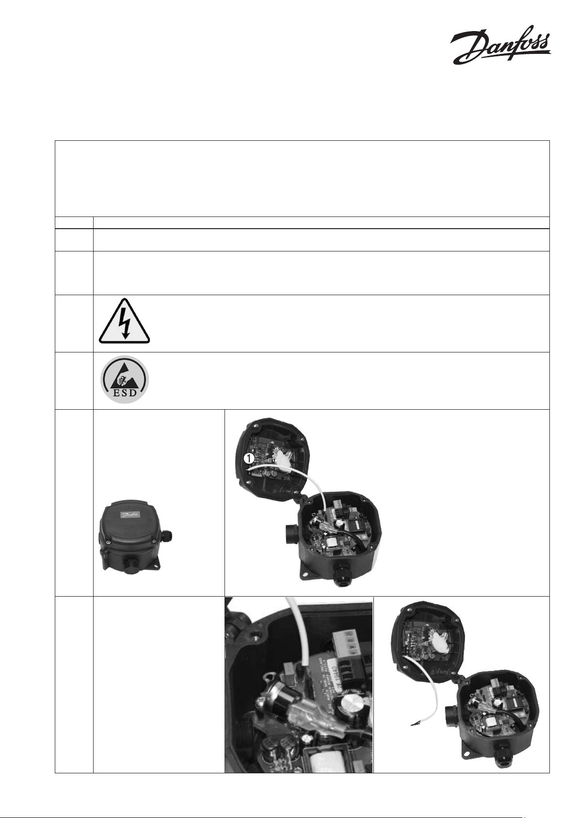
5. Locate and remove the 4
enclosure screws using the hex
driver.
Then carefully open the hinged
housing. The Infrared (IR) sensor
type is located in lid .
6. Carefully remove the sensor plug
from the daughter board
connector.
© Danfoss A/S (MWA), 2015-02 DKRCI.PI.S00.D2.02 / 520H6360 1
Page 2
Step Description
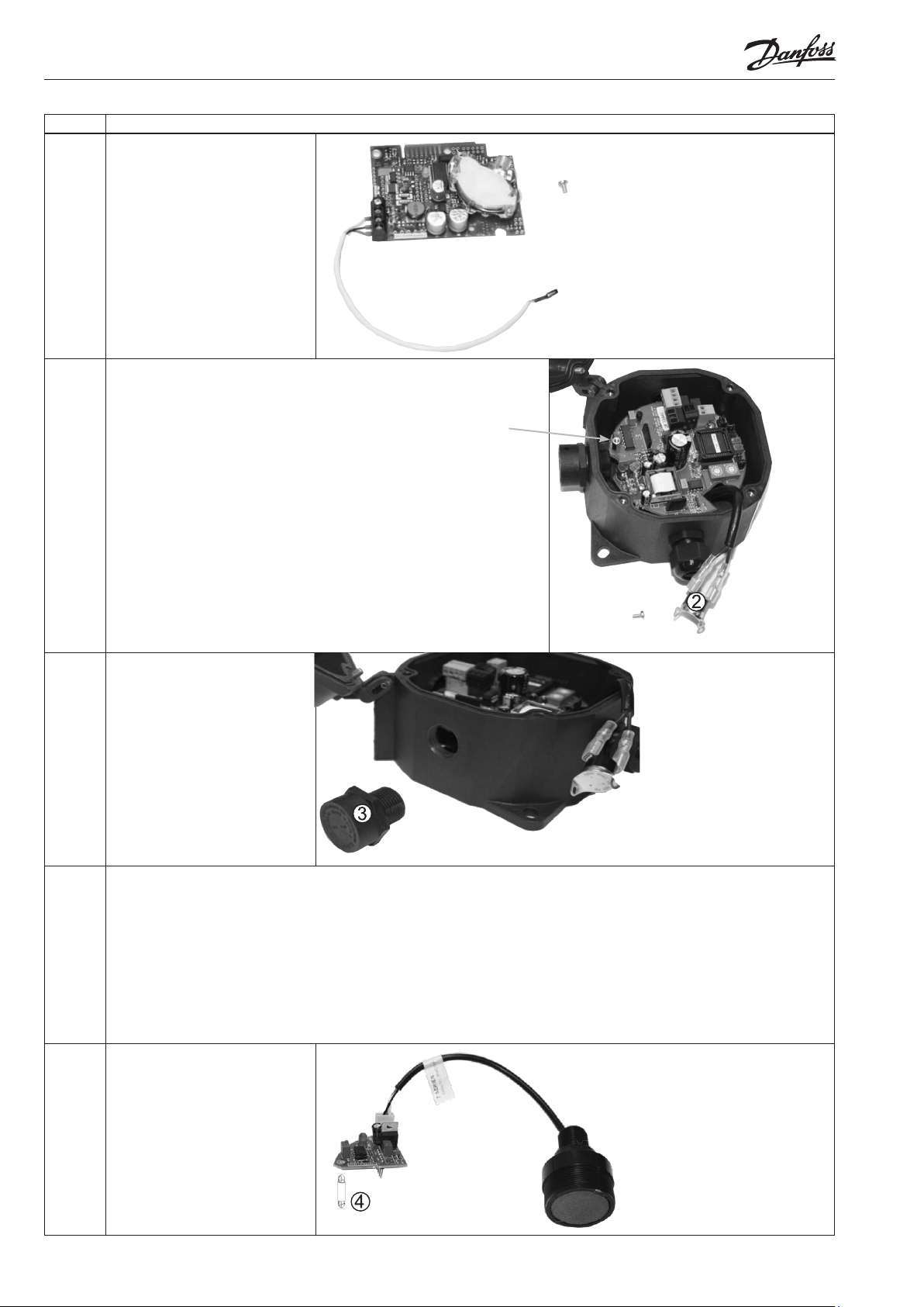
7. Unscrew and remove the sensor
board from the lid of the
enclosure using a standard
Crosshead screwdriver.
8. The IP 56 model are available in two versions:
Danfoss code no. 148H5075 and 148H5085 with heater built-in:
The thermocouple is attached to the main printed circuit board via a
screw on a metal stando or is lose inside the enclosure (see photo).
Unscrew the thermocouple if it is screwed on a metal stando and save
the screw for later. The metal stando and screw will be used to secure
the new sensor daughter board later in this procedure. If no stando was
present, proceed as below.
Danfoss code no. 148H5072, 148H5082 and 148H5092 without heater
built-in:
As no thermocouple is present, you will notice a hole on the mother board
(PCB).
Note the location of this hole as it will be used to secure a special nylon
stando (part of the upgrade kit) for the new sensor daughter board. This
nylon stando is only used when upgrading the versions without heater
built in.
9.
10. Check of mother board
11. Locate the new Sensor Upgrade
2 DKRCI.PI.S00.D2.02 / 520H6360 © Danfoss A/S (MWA), 2015-02
Unscrew the breather drain
from the enclosure.
With the GD tester it is possible to simulate GD Operation within the full ppm range, without any need for refrigerant
calibration gas locally.
Locate the GD Motherboard Tester, Danfoss code: 148H5239. Please Note: The GD Motherboard Tester is not included in
the Upgrade kit.
Locate the Instruction, GD tester for mother PCB, Literature number RI7HB252 for full instruction.
CAUTION
Before reconnecting power to GD, make sure that relevant people, managing the connecting equipment (BMS/PLC
systems) to GD has been advised, that the GD now will force Low and High alarms and generate maximum analog output
(Analog output 4-20 mA/0-5 V/0-10 V) during this test.
Kit. Note that a nylon stando is
included with the sensor daughter
board. This special nylon stando
is only used when upgrading the
versions without heater built-in.
Versions with heater built-in
already have a metal stando on
the main printed circuit board for
proper mounting of the daughter
board.
Page 3

Step Description
12. Temporarily disconnect the
provided daughter board from
the sensor.
13. Carefully mount the sensor daughter board to the main printed
14.
circuit board.
IMPORTANT: Alignment of the daughter board and the main
board header is critical.
CAUTION: Note that it is possible to be oset by one pin, and
still force the stando/screw to align, so be careful when
mounting the daughter board to the mother board (PCB).
Danfoss code no. 148H5072, 148H5082 and 148H5092
without heater built-in:
Install the nylon stando to the mother board(PCB) rst, then
carefully snap the daughter board into the mother board(PCB)
using the nylon stando as a guide. (NOTE: If the alignment is
not correct, but the stando has already been attached to the
daughter board, carefully squeeze the end of the stando that is
through the daughter board to release.)
Danfoss code no. 148H5075 and 148H5085 with heater
built-in:
Locate the existing metal stando and use the previously
saved screw to secure the daughter board to the existing metal
stando.
It is dicult to see the header where the daughter PCB plugs in. With a perpendicular view above the board, use the
stando hole and metal stando (or nylon stando) below to maintain proper alignment.
CAUTION:
If the daughter board is installed incorrectly, then on power-up the software sequence of the red and yellow LEDs may not
function as expected (or at all). The green LED, however, will likely appear to exhibit proper operation.
At Step 17 the check sequence of the LEDs are descriped at power-up
Thread the sensor cable
through the enclosure and screw
the sensor into the threaded
housing. Hand tighten the sensor
enough to just compress the
O-ring and create a seal
(approximately ¼ turn past hand
tight).
IMPORTANT:
Do not use a wrench or any other
tool. Do not over-tighten as this
will damage the O-ring.
© Danfoss A/S (MWA), 2015-02 DKRCI.PI.S00.D2.02 / 520H6360 3
Page 4

Step Description
15. Carefully connect the plug of the
sensor to the mating connector
on the main sensor board. Be
certain not to bend any pins.
Route the sensor wiring so that
it does not interfere with the
reset button and so it does not
get pinched when the cover is
replaced.
16.
17. Restore source power to the
18. Secure the lid using the 4 hex
Remove the thermocouple
from the spade connectors.
After removal, ensure the plastic
insulators cover the connectors to
prevent shorts. Then route the remaining thermocouple wiring so
that it does not interfere with or
short against other components
and so it does not get pinched
when the cover is replaced.
NOTE: The heaters are no longer
required and may be left in situ
without concern.
sensor.
Inspect the LEDs on the board
after power up to ensure that:
• The Red and Yellow blink twice
on powerup and then go out,
and
• The Green LED is on.
If this does not happen, then the
sensor was not installed properly.
nuts.
19. The device is calibrated at the factory and does not require calibration on installation. Please consult Danfoss technical
documentation for gas detecting sensors, type GDA, GDC, GDHC, GDHF, GDH (DKRCI.PD.S00.A).
IMPORTANT:
Before testing a detector on-site, it must be powered up and allowed to stabilize.
20. After restoring power and conrming normal operation, verify that the building management system (BMS) continues to
detect and communicate with the sensor (as required). If communication has been lost, re-scan the building sensors via the
BMS. No further interaction with the sensor itself should be necessary. If communication continues to be missing, remove
power from the sensor and conrm the wiring to the main PCB. Reference the sensor installation instructions provided
with the original equipment as needed.
21. The disposal of the removed electrical parts should be in accordance with the WEEE directive 2002/96/EC within the
European community and/or local regulations for countries outside this area.
4 DKRCI.PI.S00.D2.02 / 520H6360 © Danfoss A/S (MWA), 2015-02
 Loading...