

Data Sheet
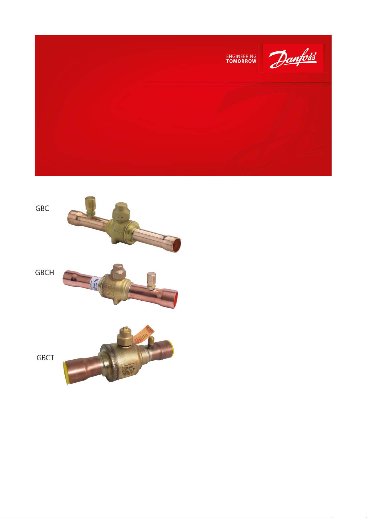
Shut-off ball valve
Type GBC, GBCH and GBCT
For CO2 application
Danfoss shut-o ball valves, type
GBC,GBCH,GBCT are manually operated shut-
o valves for CO2 refrigeration systems, in order
to open and to shut o inner ow path by
operating the valve spindle.
The valves are specically designed for intrinsic
standstill security, meaning that the valves can
withstand pressures normally arising when the
refrigeration system is shut o, i.e. during
serving or during unexpected power failure.
The valve structure and materials are designed
and tested specically for use with CO
refrigerant.
GBC and GBCH valves are designed to use in
subcritical CO2 refrigeration systems. GBCT
valves are approved for use in transcritical CO
systems.
Features:
• Bleed hole design to prevent liquid
entrapment when the valve is closed
• Sealing material especially for CO₂ to ensure
long term product reliability
• Customized brass material ensures consistent
performance under aggressive environment
• GBCH 28s~42s with stainless-steel butt
welding connections, suitable for systems
with stainless-steel piping
• GBCT with reinforced copper-iron tube
extensions to allow easy torch-brazing
installation
• UL/cUL Listed, complies with Pressure
Equipment Directive 2014/68/ EU
2
2
AI270047618978en-000601
MT
AK-PC 572
AK-SM 8XX
MBS 8250
MBS 8250
MBS 8250
MBS 8250
GBC 90 Bar
GBC 90 Bar
GBC 90 Bar
GBCT 140 Bar
GBC 90 Bar
GBC 90 Bar
AK- PC 572
®
AKVP
Gas cooler
Medium temp. load
Low temp. load
GBCT 140 Bar
GBCT 140 Bar
GBCT 140 Bar
NRV
NRV
NRV
NRV
LP
HP
009L6420
PS 20319SIG/140 BAR
TS -40 – 149 0C
ECO
0F
0C
<
<
<
<
SET
i
AKS 11
AKS 21A
AKS 11
AKS 11
AK-CC55
AKS 11
FC 103
AKS 11
AKS
2050
AKS
2050
AK-CC55
FC 103
AKVP
AKS 11
LT
CCMT
Light
MADE IN DENMARK
MADE IN DENMARK
CCMT
Light
DGS
ECO
0F
0C
<
<
<
<
SET
i
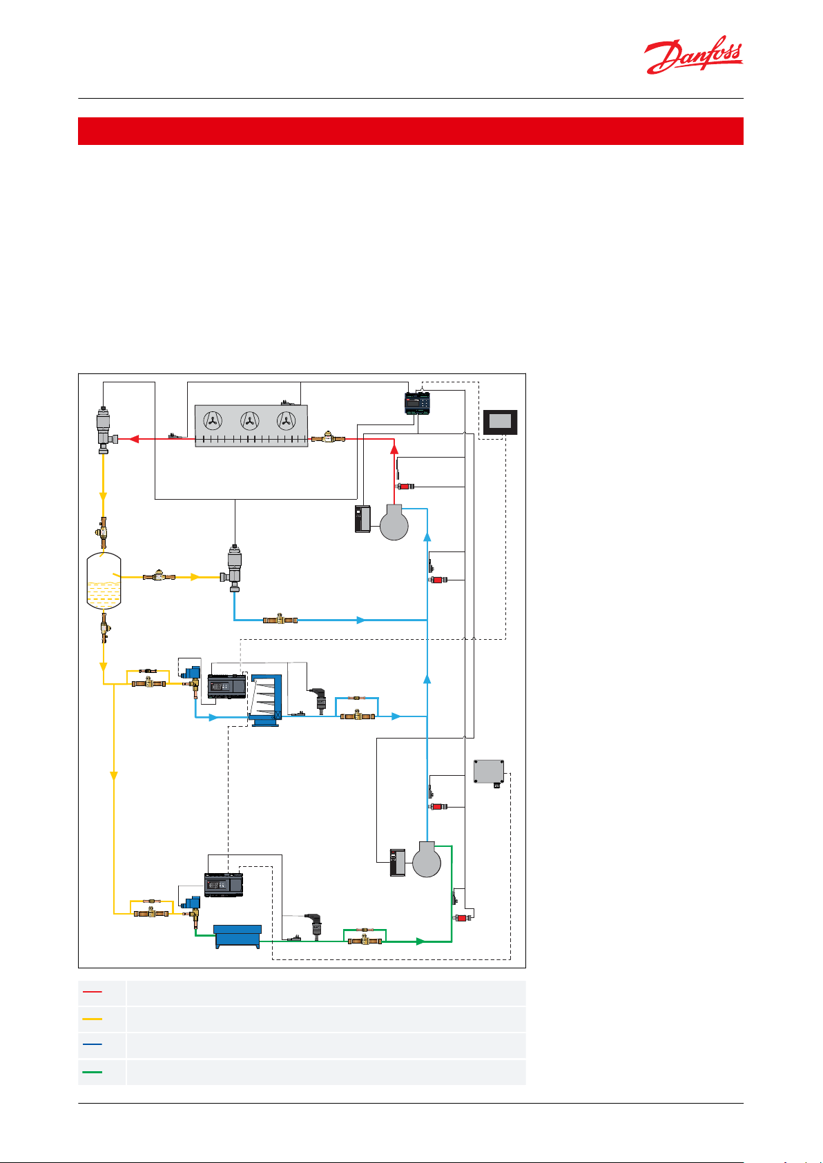
HP High Pressure (120-140 bar)
HP Receiver Pressure (60-90 bar)
LP Suction Pressure MT (35-55 bar)
LP Suction Pressure LT (25-30 bar)
Shut-o ball valve, type GBC, GBCH and GBCT
Applications
Typical applications for CO2 ball valves are:
• Display cases
• Supermarket stores
• Food Retail
• Industrial refrigeration
• Heat pump
Danfoss CO2 ball valves are designed for the following refrigerant cycles:
• GBC with PS = 45 bar, copper connections equipped, for subcritical systems
• GBCH with PS = 90/75 bar, copper/ stainless steel connections equipped, for subcritical systems
• GBCT with PS = 140 bar, reinforced copper connections (K65) equipped, for transcritical systems
Figure 1: Application
© Danfoss | Climate Solutions | 2021.03 AI270047618978en-000601 | 2

Refrigerants
R 744 (CO2)
Refrigerant oil
POE, PAG (PVE, PAO)
Shut-o ball valve, type GBC, GBCH and GBCT
Media
Table 1: Media
NOTE:
For the application use with R744 as part of a secondary loop or cascade:
1.
The design pressure of the refrigerant containing component is not less than the design pressure of the
associated components.
2.
The component is not provided with any pressure relief or pressure regulating relief valve and that a sucient
number of valves having capacity deemed adequate shall be eld installed on the refrigeration system.
3.
When the refrigeration system is de-energized, venting of R744 may occur through the pressure regulating relief
valves, and may need to be recharged, but the valve should not be defeated or bypassed.
4.
A sucient number of pressure relief and pressure regulating valves may need to be provided based upon
system capacity and located such that no stop valve is provided between the relief valve and the parts or section
of the system being protected.
© Danfoss | Climate Solutions | 2021.03 AI270047618978en-000601 | 3
Technical data
GBC
GBCH
GBCT
Max. working pressure
45 bar / 650 psig
6s - 28s: 90 bar / 1305 psig
35s - 42s: 75 bar / 1085 psig
140 bar / 2031 psig
Media temperature range
-40 °C – 100 °C / -40 °F – 212 °F
-40 °C – 100 °C / -40 °F – 212 °F
-40 °C – 149 °C / -40 °F – 300 °F
Flow direction
Single ow
Bi ow
Bi ow
Environmental transport/storage
temperature and humidity
-40 – 65 °C /-40 – 150 °F. Air humidity: RH≤95%.
Position
Inscription
Explanation
Box label; Product label
Shut-o
ball valve
Product name
Box label
GBC 6s H
Product type
Box label
009L7415
Code number for ordering
Box label
Bi-ow
Flow type
Box label
Straightway
Direction
Box label
R744(CO
2
)
Refrigerant
Box label
1/4 in ODF
Connection size and type
Box label
PS 90 bar/MWP 1305 psig
Max. working pressure in bar and psig
Box label
BE4320B
Code for production place and time
(BE = Wuqing, week 43, year 2020, weekday B = Tuesday)
Box label; Product label
MADE IN CHINA
Manufacturing site acc. to EN standards
Box label
EAN code
Barcode for individual code no.
identication accord-
ing to EAN standard
Product label
-40 °C – 100 °C
Media temperature range
Box label; Product label
Additional information: Relevant approval authority
logos
-
Shut-o ball valve, type GBC, GBCH and GBCT
Product specication
Technical data
Table 2: Technical data
CAUTION:
Danfoss recommends that GBCT valves are installed so that the HP side is oriented towards the highest
pressure side of the system when the valve is in the closed position.
GBCT CAUTION - RISK OF HIGH PRESSURE
Do not close with CO2 liquid temperature below ambient. This component shall be installed along with a pressure
relief valve set to discharge at no higher than the rated pressure of this component. This component is intended for
systems in which the critical pressure of the refrigerant will be exceeded. The relief valve shall comply with the
requirements of ASME Section VIII, be marked “UV” and sized based on the refrigeration system capacity.
An orange Hanging tag is added on all valves as per requirement of UL certicate.
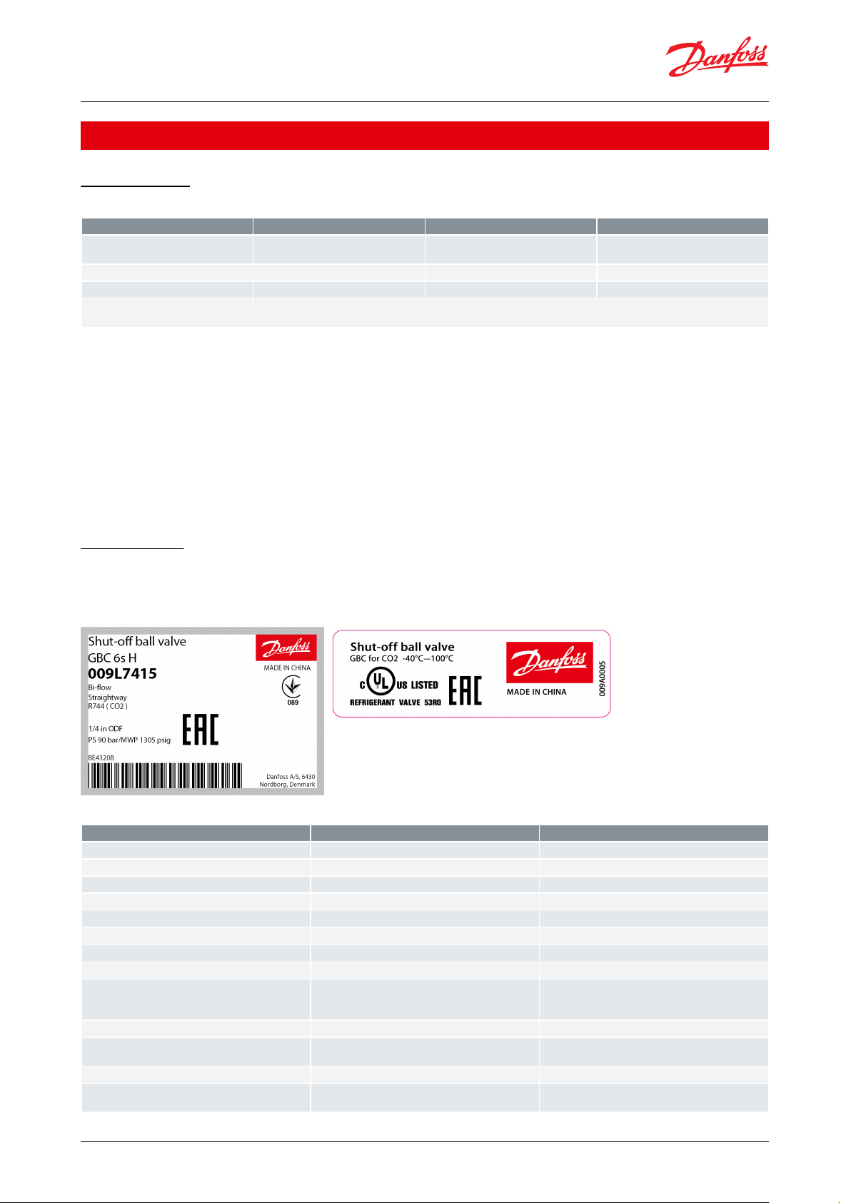
Identication
Relevant product data is available on the product and box label. An example of a box label and product label are
shown, including an explanation of the content.
Figure 2: Box label Figure 3: Product label
Table 3: Product and label text
© Danfoss | Climate Solutions | 2021.03 AI270047618978en-000601 | 4
009L6420
PS 2031PSIG/140 BAR
TS -40C to 149C
HP LP
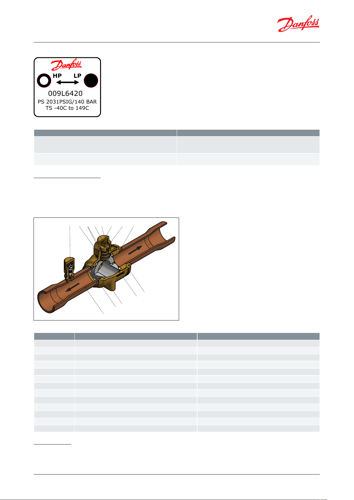
Inscription
Explanation
"HP"
Indicates where the bleed hole of ball is located and Danfoss recommends the HP
side is oriented towards the highest pressure side of system when valve is in
closed position.
"LP"
Indicates the side without bleed hole and shall be oriented towards to the low
pressure side of system when valve is in closed position.
Danfoss
9L75002
13
7
9 8
10
611
12
1
5
3
2
4
Position
Description
Material
1
Connection tube
Copper (Stainless steel for GBCH 28s~42s)
2
Valve body
Brass3Ball seat
PTFE4Valve tail
Brass5Ball
Stainless steel
6
Double O-ring seal in spindle
EPDM Rubber
7
Cap seal
PTFE8Seal cap
Brass9Spindle
Brass10Pin
Stainless steel
11
Guide ring
PTFE12Schrader valve
Stainless steel
13
Bleed hole
-
Shut-o ball valve, type GBC, GBCH and GBCT
Figure 4: Marking of GBCT
Table 4: Marking of GBCT
Design and materials
Direct ow gives maximum through-ow with minimum pressure drop across valve. The combination of laserwelded valve body (2) and valve tail (4), ball seat/seal (3), double O-ring seal in spindle (6), and cap seal (7) provides
the best tightness.
Figure 5: Design and materials
Table 5: Design and materials
Dimensions
We have chosen to show dimensions of the major versions.
© Danfoss | Climate Solutions | 2021.03 AI270047618978en-000601 | 5

H
H
1
L1
L2
L
L1
L5
L3
D
d
L
4
Mx2
Danfoss
09G80101
Type
Size
Con‐
nec‐
tion
Connection
tolerance
HH1LL1L2L3L4L5MDd
Weight
Code no.
[mm]
[mm]
[mm]
[mm]
[mm]
[mm]
[mm]
[mm]
[mm]
[mm]
[mm]
[mm]
[mm]
[kg]
without
access
port
with
access
port
GBC 6s
1/4 in.
6.35
+0.065/+0.155
50151397757322
31
M4 ×
0.7
14
1.5
0.2
009L7520
009L7553
6 mm
6.00
009L7570
009L7554
GBC 10s
3/8 in.
9.525015
1398757322
31
M4 ×
0.7
14
1.5
0.2-009L7555
3/8 in.
9.52
50151399757322
31
M4 ×
0.7
14
1.5
0.2
009L7521
-
10 mm
10.00
009L7571
009L7556
GBC 12s
1/2 in.
12.70
501516110868422
31
M4 ×
0.7
14
1.5
0.2
009L7522
009L7557
12 mm
12.00
009L7572
009L7558
GBC 16s
5/8 in.
16.005015
16112868422
31
M4 ×
0.7
14
1.5
0.2
009L7523
009L7534
16 mm
GBC 18s
3/4 in.
19.05
581918514999630
37
M4 ×
0.7
19
1.5
0.4
009L7524
009L7563
18 mm
18.00
009L7574
009L7564
GBC 22s
7/8 in.
22.22
+0.075/+0.185
581918517999630
37
M4 ×
0.7
19
1.5
0.4
009L7525
009L7536
22 mm
GBC 28s
1 1/8 in.
28.58
802520820112
1083844
M4 ×
0.7
26
1.5
0.9
009L7526
009L7565
28 mm
28.00
009L7576
009L7566
GBC 35s
1 3/8 in.
35.00
+0.09/+0.23
893025125136
1304844
M6 ×
1.0
32
1.5
1.4
009L7528
009L7567
35 mm
GBC 42s
1 5/8 in.
41.28
1103528129151
1455556
M6 ×
1.0
38
1.5
2.2
009L7529
009L7568
42 mm
42.00
009L7579
009L7569
Shut-o ball valve, type GBC, GBCH and GBCT
You will nd downloadable dimension drawings for individual code numbers on Danfoss store as part of the Visuals
tab for individual code numbers.
Weights also dier depending on the design of the individual code numbers. Weights are available as part of the
technical data for individual code numbers on Danfoss store.
GBC solder ODF/ODF, copper connections
Figure 6: GBC solder ODF/ODF
Table 6: GBC solder ODF/ODF, copper connections
© Danfoss | Climate Solutions | 2021.03 AI270047618978en-000601 | 6

L
H1
H
L1 L1
L3
L5
D
L4
Mx2
6s -16s
NON-AP
ONLY
Type
Size
Con‐
nec‐
tion
Connection
tolerance
HH1LL1L2L3L4L5MDd
Weight
Code no.
[mm]
[mm]
[mm]
[mm]
[mm]
[mm]
[mm]
[mm]
[mm]
[mm]
[mm]
[mm]
[mm]
[kg]
without
access
port
with ac‐
cess port
GBCH 6s
1/4 in.
6.35
+0.065/+0.155
50151395757322
31
M4 ×
0.7
14
1.5
0.2
009L7415
009L7581
6 mm
6.00
009L7395
009L7580
GBCH 10s
3/8 in.
9.52
50151397757322
31
M4 ×
0.7
14
1.5
0.2
009L7416
009L7582
10 mm
10.00
009L7396
009L7583
GBCH 12s
1/2 in.
12.70
50151618868422
31
M4 ×
0.7
14
1.5
0.2
009L7417
009L7585
12 mm
12.00
009L7397
009L7584
GBCH 16s
5/8 in.
16.005015
16110868422
31
M4 ×
0.7
14
1.5
0.2
009L7418
009L7586
16 mm
GBCH 18s
3/4 in.
19.05
581918512999630
37
M4 ×
0.7
19
1.5
0.4
009L7419
009L7588
18 mm
18.00
009L7399
009L7587
GBCH 22s
7/8 in.
22.22
+0.075/+0.185
581918515999630
37
M4 ×
0.7
19
1.5
0.4
009L7420
009L7589
22 mm
L1
L1
L2
L
D
H1
H
L3
L4
Mx2
Shut-o ball valve, type GBC, GBCH and GBCT
GBCH solder ODF/ODF, copper connections
Figure 7: GBC solder ODF/ODM
Table 7: GBCH solder ODF/ODF, copper connections
GBCH butt weld, stainless steel connections
Figure 8: GBC solder ODM/ODM, copper connections
© Danfoss | Climate Solutions | 2021.03 AI270047618978en-000601 | 7

Type
Size
Con‐
nec‐
tion
Connection
tolerance
HH1LL1L2L3L4MDdWeight
Code no.
[mm]
[mm]
[mm]
[mm]
[mm]
[mm]
[mm]
[mm]
[mm]
[mm]
[mm]
[mm]
[kg]
without
access
port
GBCH 28s
28 mm
28
-0.1/+0.1
802520865115
116
38
M4 ×
0.7
25.5
1.5
0.9
009L7406
GBCH 35s
35 mm
358930
25179146
141
48
M6 ×
1.0
32
1.5
1.5
009L7410
GBCH 42s
42 mm
42
1103528188162
156
55
M6 ×
1.0
38
1.5
2.5
009L7411
L
H1
H
L1 L1
L3
L5
D
L4
Mx2
6s -16s
NON-AP
ONLY
Type
Size
Con‐
nec‐
tion
Connection
tolerance
HH1LL1L3L4L5MD
Weight
Code no.
[mm]
[mm]
[mm]
[mm]
[mm]
[mm]
[mm]
[mm]
[mm]
[mm]
[mm]
[kg]
without
access
port
with ac‐
cess port
GBCT 6s
1/4 in.
6.35
+0.051/+0.155
571412776922N/A
M4 ×
0.7
13
0.2
009L6415
-
5714127755
N/A44N/A130.3-009L6581
GBCT 10s
3/8 in.
9.52
571413297222N/A
M4 ×
0.7
13
0.2
009L6416
-
5714132958
N/A46N/A130.3-009L6582
GBCT 12s
1/2 in.
12.70
5714139107522N/A
M4 ×
0.7
13
0.2
009L6417
-
57141391061
N/A50N/A130.3-009L6585
GBCT 16s
5/8 in.
15.88
5714148138022N/A
M4 ×
0.7
13
0.2
009L6418
-
57141481366
N/A54N/A130.3-009L6586
GBCT 18s
3/4 in.
19.058732
1481778
N/A30N/A190.7
009L6419
009L6588
GBCT 22s
7/8 in.
22.228732
1852096
N/A40N/A190.7
009L6420
009L6589
GBCT 28s
1 1/8 in.
28.58
+0.075/+0.185
102371852495
N/A40N/A251.3
009L6406
009L6451
GBCT 35s
1 3/8 in.
34.93
1033520525102
N/A44N/A322.0
009L6410
009L6453
GBCT 42s
1 5/8 in.
41.28
+0.075/+0.203
1134024028120
N/A50N/A382.9
009L6411
009L6454
GBCT 54s
2 1/8 in.
53.98
1445227535138
N/A56N/A516.1
009L6412
009L6456
Shut-o ball valve, type GBC, GBCH and GBCT
Table 8: GBCH butt weld, stainless steel connections
GBCT solder ODF/ODF, copper connections
Figure 9: GBCT solder ODF/ODF, copper connections
Table 9: GBCT solder ODF/ODF, copper connections
© Danfoss | Climate Solutions | 2021.03 AI270047618978en-000601 | 8

Type
Inlet
Outlet
mm connections
Inch connections
GBC
Solder ODF
Solder ODF
6 mm x 6 mm
10 mm x 10 mm
12 mm x 12 mm
16 mm x 16 mm
18 mm x 18 mm
22 mm x 22 mm
28 mm x 28 mm
35 mm x 35 mm
42 mm x 42 mm
¼ in x ¼ in
⅜ in x ⅜ in
½ in x ½ in
⅝ in x ⅝ in
¾ in x ¾ in
⅞ in x ⅞ in
1
1
⁄8 in x 1 1⁄8 in
1
3
⁄8 in x 1 3⁄8 in
1
5
⁄8 in x 1 5⁄8 in
GBCH
Solder ODF
Solder ODF
6 mm x 6 mm
10 mm x 10 mm
12 mm x 12 mm
16 mm x 16 mm
18 mm x 18 mm
22 mm x 22 mm
¼ in x ¼ in
⅜ in x ⅜ in
½ in x ½ in
⅝ in x ⅝ in
¾ in x ¾ in
⅞ in x ⅞ in
Butt weld
Butt weld
28 mm x 28 mm
35 mm x 35 mm
42 mm x 42 mm
-
GBCT
Solder ODF
Solder ODF
-
¼ in x ¼ in
⅜ in x ⅜ in
½ in x ½ in
⅝ in x ⅝ in
¾ in x ¾ in
⅞ in x ⅞ in
1
1
⁄8 in x 1 1⁄8 in
1
3
⁄8 in x 1 3⁄8 in
1
5
⁄8 in x 1 5⁄8 in
2
1
⁄8 in x 2 1⁄8 in
Shut-o ball valve, type GBC, GBCH and GBCT
Connections
Standard GBC, GBCH, GBCT versions can be provided with straightway, connection types solder ODF or butt weld in
a wide variety of connection sizes. Solder ODF versions are with extended ends copper connections, butt weld
versions with stainless steel connections.
For details on availability, see Ordering
Connection table
Table 10: Connection table
© Danfoss | Climate Solutions | 2021.03 AI270047618978en-000601 | 9

Type
Solder ODF / ODF Connection
Kv
(1)
Cv
(1)
Max. working
pressure:
PS/MWP
Media tem‐
perature
range
Code no.
Multi pack
[in.]
[mm]
[m3/h]
[gal/min]
without
access port
with
access port
Qty/ pack
GBC 6s
1/4-1.74
2.01
45 bar /
650 psig
-40 °C – 100 °C
/
-40 °F – 212 °F
009L7520
009L755325-61.74
2.01
009L7570
009L7554
25
GBC 10s
3/8-7.52
8.69
009L7521
009L755525-107.52
8.69
009L7571
009L7556
25
GBC 12s
1/2-12.92
14.94
009L7522
009L755725-1212.92
14.94
009L7572
009L7558
25
GBC 16s
5/81615.66
18.10
009L7523
009L7534
25
GBC 18s
3/4-21.93
25.35
009L7524
009L756325-1821.93
25.35
009L7574
009L7564
25
GBC 22s
7/82233.34
38.54
009L7525
009L7536
25
GBC 28s
1 1/8-62.25
71.96
009L7526
009L75655-2862.25
71.96
009L7576
009L7566
5
GBC 35s
1 3/83592.76
107.23
009L7528
009L7567
5
GBC 42s
1 5/8-134.76
155.78
009L7529
009L75684-42134.76
155.78
009L7579
009L7569
4
Shut-o ball valve, type GBC, GBCH and GBCT
Ordering
GBC,GBCH,GBCT code numbers described in this data sheet are standard code numbers, i.e. made to stock.
Besides code numbers made to stock GBC,GBCH,GBCT is also made to order. Make to order options include:
• Mechanical connection type
• Mechanical connection size
• Access port size
Multipack contains several items, individually packed, so that customers can purchase 1 item and receive all relevant
documentation.
GBC solder ODF/ODF, copper connections
Figure 10: GBC without access
port, solder ODF/ODF
Figure 11: GBC with access port,
solder ODF/ODF
Table 11: GBC solder ODF/ODF, copper connections
(1)
(1)
Calculated based on uid dynamic equations
Calculated based on uid dynamic equations
© Danfoss | Climate Solutions | 2021.03 AI270047618978en-000601 | 10

Type
Solder ODF/ODF
connection
Kv
(1)
Cv
(1)
Max. working
pressure:
PS/MWP
Media tempera‐
ture range
Code no.
Multi pack
[in.]
[mm]
[m3/h]
[gal/min]
without
access
port
with access port
Qty/ pack
GBC 6s H
1/4-1.78
2.06
90 bar /
1305 psig
-40 °C – 100 °C
/
-40 °F – 212 °F
009L7415
009L7581
25-6
1.78
2.06
009L7395
009L7580
25
GBC 10s H
3/8-6.31
7.29
009L7416
009L7582
25-10
6.31
7.29
009L7396
009L7583
25
GBC 12s H
1/2-12.87
14.88
009L7417
009L7585
25-12
12.87
14.88
009L7397
009L7584
25
GBC 16s H
5/81611.77
13.61
009L7418
009L7586
25
GBC 18s H
3/4-31.07
35.92
009L7419
009L7588
25-18
31.07
35.92
009L7399
009L7587
25
GBC 22s H
7/82224.47
28.29
009L7420
009L7589
25
Type
Solder ODF/ODF
connection
Kv
(1)
Cv
(1)
Max. work‐
ing pres‐
sure:
PS/MWP
Media tempera‐
ture range
Code no.
Multi pack
[in.]
[mm]
[m
3
/h]
[gal/min]
without ac‐
cess port
with access
port
Qty/ pack
GBC 28s H-28
96.72
111.81
90 bar /
1305 psig
-40 °C – 100 °C
/
-40 °F – 212 °F
009L7406-5
GBC 35s H-35
106.95
123.63
75 bar /
1088 psig
009L7410-5
GBC 42s H-42
150.98
174.53
009L7411-4
Shut-o ball valve, type GBC, GBCH and GBCT
GBCH solder ODF/ODF, copper connections
Figure 12: GBCH without access
port,solder ODF
Figure 13: GBCH with access
port,solder ODF
Table 12: GBCH solder ODF/ODF, copper connections
(1)
(1)
Calculated based on uid dynamic equations
Calculated based on uid dynamic equations
GBCH butt weld, stainless steel connections
Figure 14: GBCH without access
port,butt weld
Table 13: GBCH butt weld, stainless steel connections
(1)
(1)
Calculated based on
Calculated based on
uid dynamic equations
uid dynamic equations
© Danfoss | Climate Solutions | 2021.03 AI270047618978en-000601 | 11

Type
Connec‐
tion
Kv
Cv
Max. working
pressure:
PS/MWP
Media tempera‐
ture range
Code no.
Multi pack
[in.]
[m3/h]
[gal/min]
without
access port
with access port
Qty/ pack
GBCT 6s
1/4
0.9
1.0
140 bar /
2031 psig
-40 °C – 149 °C /
-40 °F – 300 °F
009L6415
009L6581
30
GBCT 10s
3/8
3.7
4.3
009L6416
009L6582
30
GBCT 12s
1/2
5.4
6.2
009L6417
009L6585
30
GBCT 16s
5/8
10.4
12.1
009L6418
009L6586
30
GBCT 18s
3/4
16.4
19.0
009L6419
009L6588
18
GBCT 22s
7/8
23.7
27.5
009L6420
009L6589
18
GBCT 28s
1 1/8
42.3
48.9
009L6406
009L6451
4
GBCT 35s
1 3/8
67.1
77.6
009L6410
009L6453
4
GBCT 42s
1 5/8
83.1
96.1
009L6411
009L6454
4
GBCT 54s
2 1/8
171.3
198.0
009L6412
009L6456
2
Type
Valve connection size
Industrial pack [pcs]
Code no.
[inch]
[mm]
GBC/GBCH 6s - 22s
1/4 – 7⁄8
6 – 22
6
009L7210
GBC/GBCH 28s - 35s
1 1/8 – 1 3/8
28 – 35
3
009L7211
GBC/GBCH 42s
1 5⁄8423
009L7212
Shut-o ball valve, type GBC, GBCH and GBCT
GBCT solder ODF/ODF, copper connections
Figure 15: GBCT without access
port,solder ODF
Figure 16: GBCT with access
port,solder ODF
Table 14: GBCT solder ODF/ODF, copper connections
Spare parts
Figure 17: Seal cap kit
Table 15: Seal cap kit
Figure 18: Bracket kit
© Danfoss | Climate Solutions | 2021.03 AI270047618978en-000601 | 12

Type
Valve connection size
Industrial pack [pcs.]
Code no.
[inch]
[mm]
GBC/GBCH 6s -16s
1/4 – 5⁄8
6 – 16
12
009G7084
GBC/GBCH 18s - 22s
3/4– 7⁄8
18 – 22
12
009G7085
GBC/GBCH 28s
1 1⁄82810
009G7086
GBC/GBCH 35s
1 3⁄8355
009G7087
GBC/GBCH 42s
1 5⁄8424
009G7088
Shut-o ball valve, type GBC, GBCH and GBCT
NOTE:
The spare parts are only for GBC and GBCH. For GBCT spare parts, please consult Danfoss
© Danfoss | Climate Solutions | 2021.03 AI270047618978en-000601 | 13

Type
File name
Document type
Document topic
Approval authority
GBC, GBCH, GBCT
Д-DK.РА01.B.02567_19
EAC Declaration
Machinery & Equipment
EAC RU
GBC, GBCH, GBCT
Д-DK.БЛ08.B.02139_19
EAC Declaration
PED
EAC RU
GBC, GBCH
033F4001.AE
Manufacturers Declaration
PED
Danfoss
GBC, GBCH
033F4002.AE
EU Declaration
PED
Danfoss
GBCT
033F4003.AA
Manufacturers Declaration
PED
Danfoss
GBC, GBCH, GBCT
033F4006
Manufacturers Declaration
China RoHS
Danfoss
GBC, GBCH, GBCT
033F4010
Manufacturers Declaration
RoHS
Danfoss
GBCT
033F4013.AA
EU Declaration
PED
Danfoss
GBC, GBCH
UA.089. D. 00189-17
UA Declaration
PED
LLC CDC EURO TYSK
GBC, GBCH
UA.TR-089.0995-17
Pressure - Safety Certicate
PED
LLC CDC EURO TYSK
GBC, GBCH, GBCT
UL SA7200
Mechanical - Safety Certicate
UL
UL
Shut-o ball valve, type GBC, GBCH and GBCT
Certicates, declarations, and approvals
The list contains all certicates, declarations, and approvals for this product type. Individual code number may have
some or all of these approvals, and certain local approvals may not appear on the list.
Some approvals may change over time. You can check the most current status at danfoss.com or contact your local
Danfoss representative if you have any questions.
© Danfoss | Climate Solutions | 2021.03 AI270047618978en-000601 | 14

Online support
Danfoss oers a wide range of support along with our products, including digital product information, software,
mobile apps, and expert guidance. See the possibilities below.
The Danfoss Product Store
The Danfoss Product Store is your one-stop shop for everything product related—no matter where
you are in the world or what area of the cooling industry you work in. Get quick access to essential
information like product specs, code numbers, technical documentation, certications, accessories,
and more.
Start browsing at store.danfoss.com.
Find technical documentation
Find the technical documentation you need to get your project up and running. Get direct access to
our ocial collection of data sheets, certicates and declarations, manuals and guides, 3D models
and drawings, case stories, brochures, and much more.
Start searching now at www.danfoss.com/en/service-and-support/documentation.
Danfoss Learning
Danfoss Learning is a free online learning platform. It features courses and materials specically
designed to help engineers, installers, service technicians, and wholesalers better understand the
products, applications, industry topics, and trends that will help you do your job better.
Create your Danfoss Learning account for free at www.danfoss.com/en/service-and-support/learning.
Get local information and support
Local Danfoss websites are the main sources for help and information about our company and
products. Find product availability, get the latest regional news, or connect with a nearby expert—all
in your own language.
Find your local Danfoss website here: www.danfoss.com/en/choose-region.
Danfoss can accept no responsibility for possible errors in catalogues, brochures and other printed material. Danfoss reserves the right to alter its
products without notice. This also applies to products already on order provided that such alterations can be made without subsequential
changes being necessary in specications already agreed. All trademarks in this material are property of the respective companies. Danfoss and
the Danfoss logotype are trademarks of Danfoss A/S. All rights reserved.
© Danfoss | Climate Solutions | 2021.03 AI270047618978en-000601 | 15
 Loading...