

Page 1
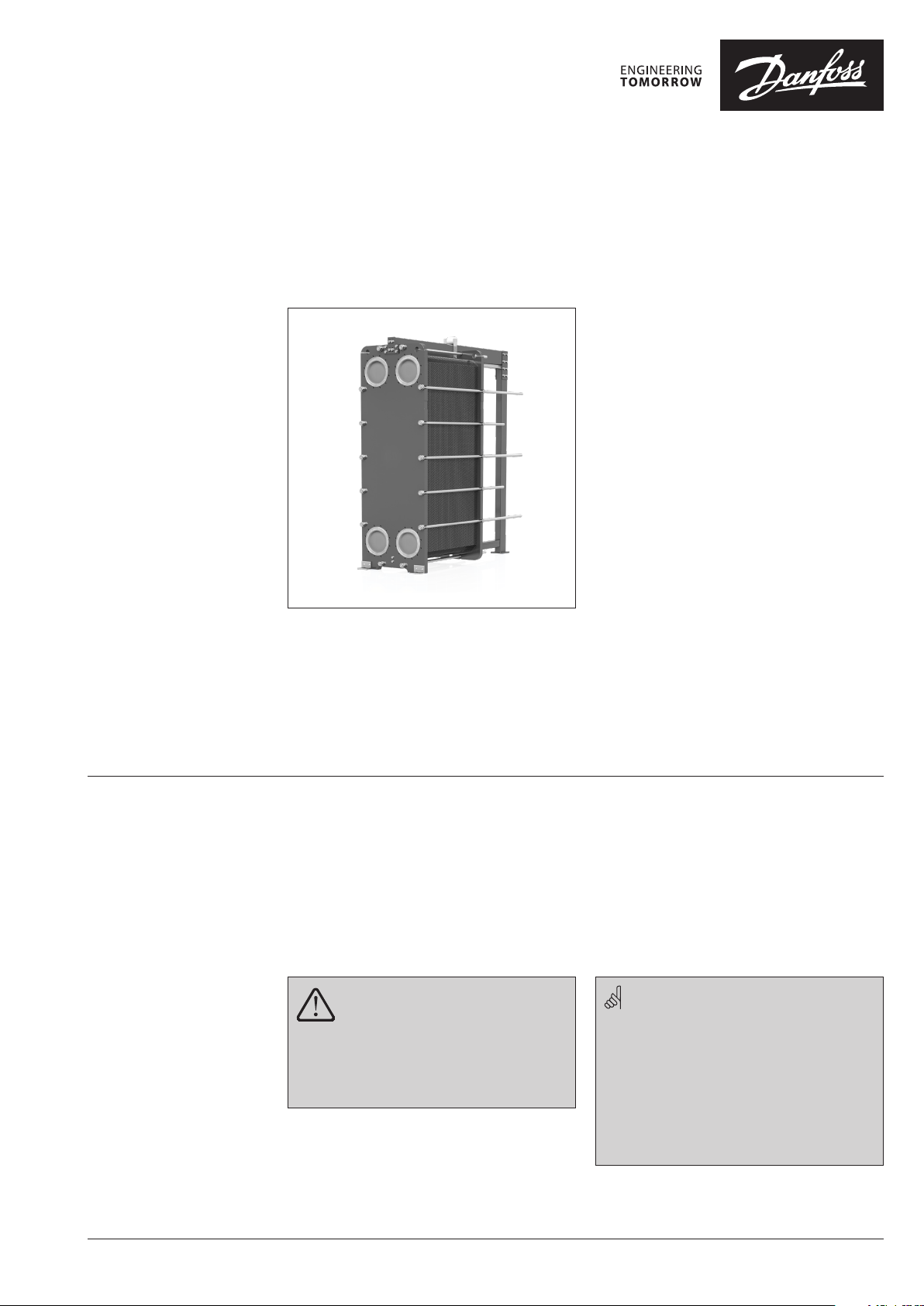
Operating guide
Gasketed Heat Exchangers
Introduction
This user guide is a guide for installation,
commissioning, operation and maintenance of
plate type heat exchangers supplied by Danfoss.
It is meant for those who are responsible for the
installation, the use and maintenance of the heat
exchangers. We recommend that you read this
user guide carefully before commencing any
work.
This user guide is applicable for all plate type
heat exchangers produced and supplied by
Danfoss if there is no local country specific
deviation from it (in a whole and/or in a part).
Danfoss can not be held responsible or liable
for damage as a result of incorrect installation,
use and/or maintenance of Danfoss plate type
heat exchanger or damage caused by as not
complying with the instructions in this user
guide.
Please note that our plate type heat
exchangers are specially designed and built
for the maximum design conditions (pressures,
temperatures, capacities and type of fluids)
provided by the customer and stated on the
nameplate.
Sudden pressure peaks within or beyond the
maximum operating pressure (or pressure
surges) which can occur during start-up or
stopping of the system can severely damage
the heat exchanger and should be prevented.
Danfoss can not be held responsible for any
damage as a result of any operation deviating
from the original design conditions.
Safety alert notices The following must always be observed when
installing or servicing plate heat exchangers:
• Comply with national/local safety regulations
• Ensure that the heat exchanger is
unpressurized and completely drained
• Ensure that the heat exchanger is cooled
down to a temperature below 40 °C (104 °F)
Warning symbols refer to safety alert notices.
Warning/safety notices should be observed
carefully to prevent:
Personal injury caused by:
• Wrong transport/lifting
• Burning/free zing as a result of touching
parts with ex treme temperatures.
• Burning/free zing/poisoning as a result of
uncontrolled release of p ressurized media
• Contact with chemicals
• Touching sharp edges of e.g. plates
Equipment damage caused by:
• Wrong transport/lifting
• Liquid hammering
• External fo rces
• Corrosion
• Chemical action
• Erosion
• Material fatigue
• Thermal and/or mechanical shock
• Freezing
• Blocking of the hea t exchanger due to particl es
© Danfoss | 2020.10 AQ356845617175en-010101 | 1
Page 2
Operating guide Gasketed Heat Exchangers
Cb
/L
Marking field
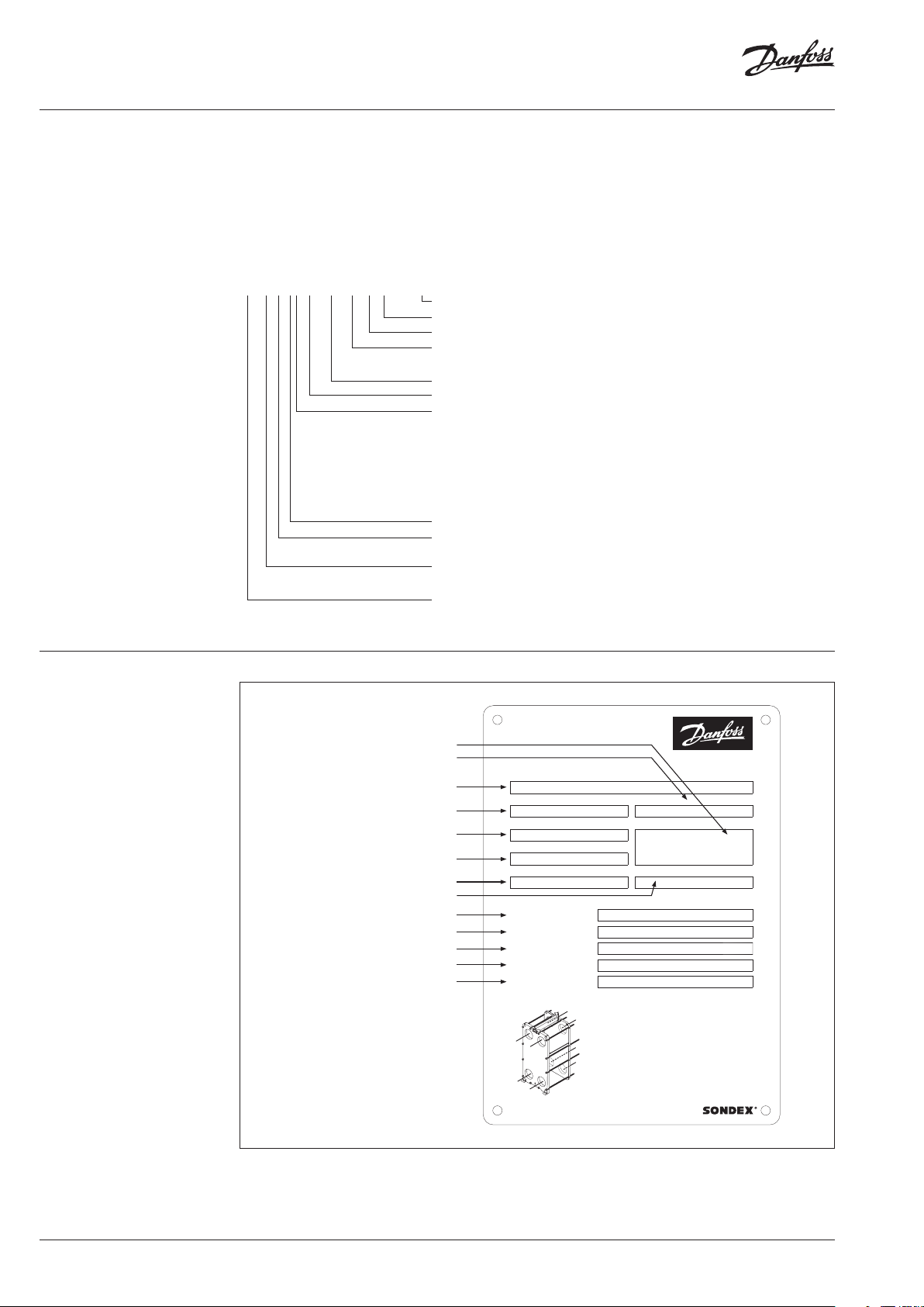
General Identification of the heat exchanger
All plate type heat exchangers supplied by Danfoss are provided with a name plate positioned on the
front (head) of the heat exchanger. Additional nameplates can be found elsewhere if specified by the
client and ordered as an option.
On this name plate main technical details of the heat exchanger are specified. Before installation
please make sure that the intended application is compliant with the name plate application data and
use limitations.
SW19A-IG25-40-TMTL38-LIQUID
Liquid/Steam-Liquid/Condenser/Evaporator
38 = % of plates that are „Thermal long“
TL = Thermal long, TK = Thermal short
TM = Thermal mix (pairs TL+TK) – in this case 62% of the plates
consists of TK/TL combination
40 = Number of plates
25 = 25 Bar nominal pressure (6/10/16/25 available)
S = Best frame, with carrier bar and roller. Connection on follower
side possible. Lock – bush on follower side (single sided disassembly
possible)
G = Medium frame, simple carrier bar without roller. Connection on
follower side possible. No lock bush on follower side.
Each heat exchanger comes with a
data list specifying key components
and relevant accessories as per
specific customer order, heat
exchanger dimensions, and an
assembly drawing.
For more detailed technical details
please contact our support team
T = No frame, connection on follower side not possible, only blue
color, no lock bush, no carrier bar
Industrial = painted version / F = food (glass blasted stainless steel)
Gasket type: IF blank = Sonderlock, A = Hang on type A, B = Hang
on type B (rare, mostly sold in US)
Approximate area per plate. (Not all plates are named according to
this rule)
S = Standard plate, SF = Freeflow plate, SW = Semi-welded, SEC =
evaporator, SWC = condenser, A = AHRI certified type
Name plate
(example, may vary)
, e.g. CE, NoBo, ASME U, DNV-GL etc.
Month and year of production
Tag number
Type designation
Serial number
Nominal assembly measure
Min./max design temperature
Dierential pressure
Inlet / outlet connections
Design pressure
Test pressure
Total internal volume
Fluid type
Tag no.
Unit No. 1
Plate heat exchanger type Month and year
S19A-DG16
Serial no. Marking
PHE085370
A-measure nominal (tolerance -1.5%)
141
Min. / Max. design temperature Differential pressure
0 11016
/°
Inlet > Outlet /
Design pressure/bar
Test pressure/bar
Volume
Fluid /
F1
F1
F2
A-measure
F4
F3
Manufactured by Danfoss A/S, 6430 Nordborg, Denmark - Tel. +45 74 88 22 22
09-2020
This product fulfils PED
requirements for SEP / Art.4,
Sec.3.
mm
Hot side
F1 > F4
16
20
15,0
Water
B1
B2
B4
Do not exceed above values at any time.
B3
Please read instruction manual before
installation, operation and maintenance.
MADE IN DENMARK
/
Cold side
F3 > F2
16
20
15,0
Water
MM-YYYY
ar
2 | AQ356845617175en-010101 © Danfoss | 2020.10
Page 3
Operating guide Gasketed Heat Exchangers
Name plate
(example, may vary)
(continuous)
SONDEX A/S
Plate heat
exchanger Type
Serial No
Nominal
capacity [k/w]
Assembly measure min. [mm]
Max working
pressure [Bar]
Max dierential pressure [Bar]
Volume Product
side [ltr]
Working temp.
min. [°C]
Product / Medium Product / Medium
IMPORTANT:
1) The plate heat exchanger must not be
assembled under the stated minimum assembling
measure. Please contact your SONDEX A/S
distributor if the heat exchanger is leaking when
tightened to the minimum measurement.
2) The starting up must be done without schocks
and against closed valves.
3) Max. working pressure may not be exceeded at
any time.
Build year
Heat surface
[m2]
Flow [l/h]
Max test
pressure [Bar]
Volume Medium
side [ltr]
Working temp.
max. [°C]
SONDEX A/S DK-6000 KOLDING DENMARK
Design: Gasketed heat
exchanger
(may vary)
1
2
3
4
6
5
7
9
10
8
AQ356845617175en-010101 | 3© Danfoss | 2020.10
Page 4
Operating guide Gasketed Heat Exchangers
Start plate
Left plate
Left plate
Right plate
End plate
Flow arrows shown are only indicative
Design: Gasketed heat
exchanger
(may vary)
(continuous)
1 Roller (for certain types)
Making it easier for service and maintenance to
slide the follower back and forth
2 Carrying bar
Connects and carries the head (frame plate),
plates (plate pack) and follower (pressure plate)
3 Column
Ensures plate pack support usually for mid ad
larger heat exchangers
4 Name Plate
Carries all the information about the heat
exchanger (design temperature, operating
pressure, testing pressure,…)
5 Follower
Back (pressure plate) of the gasketed heat
exchanger where we can connect it to the
pyping system
7 Plate
The plate pack package consists of plates with a
groove along the rim of the plate and around the
ports. The number of plates is, as well as size and
dimension dependant on the thermal output
required.
8 Anchoring brackets
Are used to prevent the heat exchanger’s
movement on the foundation/floor surface or
mouting frames
9 Guiding bar
Connects and keeps in place the plates (plate
pack package) at the lower part of heat
exchanger
10 Tie bolt
Are used to press the plate package together.
Size and number depends on the type of heat
exchanger.
6 Head
Front (frame plate) of gasketed heat exchanger
where we can connect it to the pyping system
Frame
The heat exchanger consists of a frame plate (head), a pressure plate (follower), a carrying bar, a
guiding bar and a column. To all these components we usually refer as a frame.
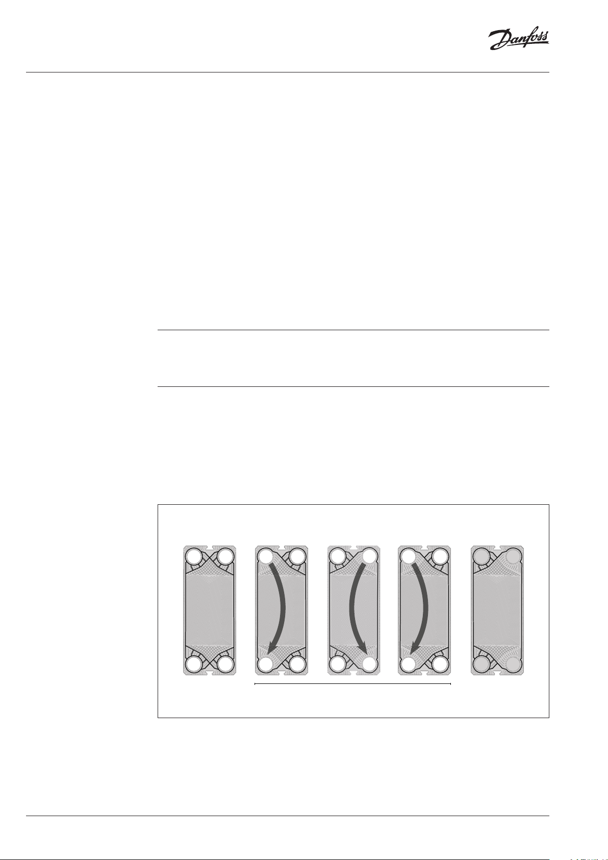
Single plates
Right (R)/ Left (L) plates
Plates are designed in such a way that they can be used both as right and left plates by alternately
turning them 180°.
On a right plate the flow runs from porthole 2 to 3 or reverse from porthole 3 to 2.On a left plate the
flow runs from porthole 1 to 4 or reverse from porthole 4 to 1.
The opening of the corner portholes is described in a “plate code index”. For instance 1234 means that
all corner portholes are open. Every plate can be identified by the gasket configuration, the plate code
index, and the plate geometry (e.g. thermal short or thermal long geometry).
F1
F4
Connections:
F1 > F4 (Flow 1)
F2 > F3 (Flow 2)
Special gasket
Used for start plate only.
All portholes are gasketed
F2
F3
Standard gasket.
Used on all plates except the first plate
Each plate are rotated 180° relative to the plate before/after
Used on all plates except the first plate
Each plate are rotated 180° relative to the plate before/after
Standard gasket.
Single plates x N
Standard gasket.
Used on all plates except the first plate
Each plate are rotated 180° relative to the plate before/after
Standard gasket.
Used on all plates except the first plate.
Note that the plate are without port holes
4 | AQ356845617175en-010101 © Danfoss | 2020.10
Page 5
Operating guide Gasketed Heat Exchangers
Design: Gasketed heat
exchanger
(may vary)
(continuous)
Fishbone design
TL plate TK plate
Gaskets
The channel gasket material is carefully selected to match the combination of temperature and
chemical resistance requirements.
The following gasket type are used in Danfoss gasketed plate type heat exchangers:
• D-Lock gaskets
• Sonderlock gaskets
• Hang-on gaskets
• Glued gaskets
If any recommendations are required please contact our representative in your country
AQ356845617175en-010101 | 5© Danfoss | 2020.10
Page 6

Operating guide Gasketed Heat Exchangers
Installation
Transport and lifting
WARNING:
To prevent perso nal injur y always use
approp riate hoist ing equipme nt. If you
are to lif t the heat exc hanger itse lf, straps sh ould
be used. T he straps sho uld be placed a s shown on
the pict ure below.
Usually the heat exchanger will be supplied
horizontally on a pallet.
The back side of the head will then be secured to
the pallet. This allows the unit to be transported
by means of a forklift truck.
• Raising of the unit (see Figure 1):
• Remove all tightening elements from the
pallet
• Place straps around opposite bolts on each
side of the column (1)
• Lift the unit vertically from the pallet (2)
• Remove the pallet securely(3)
• Slowly lower the heat exchanger to the floor
(4)
• Remove the straps atthe unit bottomside (5)
• Lift one-sided in an appropriate lifting angle
(6) and follow the raising of the unit carefully.
Avoid any bumps or shocks.
• When lifting all the personal safety
measurements should be considered and
keep safety distance
• If heat exchanger is supplied with feet
mounted on the header make sure they are
not damaged
• Once the heat exchanger is in upright position
place the straps in the dedicated lifting eyes
(where applicable)
(7) and lift the unit to its final position (8)
• Remove the straps and mount the heat
exchanger securely to the floor or mounting
frame
4
2
11
3
6
8
5
Figure 1
Never lift t he heat exch anger usin g any other meth od than desc ribed above. Neve r use the
connections, studs or any
interme diate plate s ( fitted) for l ifting (fig . 1).
7
6 | AQ356845617175en-010101 © Danfoss | 2020.10
Page 7

Operating guide Gasketed Heat Exchangers
Installation
(continuous)
Foundation
Install the heat exchanger on a flat foundation or mounting frames providing sufficient support for
the frame of heat exchanger.
Space
Ensure enough space around the plate heat exchanger for servicing the unit (renewal of plates,
tightening of the plate pack).
Min.
Figure 2
We recommend to leave Min. = 1.5 x W (where “W” is the width of header) on each side of the heat
exchanger for maintenance access. See Fig. 2.
Drip tray
Replaceable plate heat exchangers involve a risk of leakage.
It is recommended to take this into account while installing. Preferably install a drip tray underneath
the heat exchanger to prevent leakages onto the floor and/or harm to electrical equipment.
Safety cover
If the heat exchanger is being used with temperatures above 60 °C or with aggressive fluids, we advise
that you cover the heat exchanger with a screen plate to prevent the risk of human exposure to the
surface and fluids.
AQ356845617175en-010101 | 7© Danfoss | 2020.10
Page 8

Operating guide Gasketed Heat Exchangers
Piping system
Filtration
If the fluid in the plate heat exchanger contains particles larger than Ø 0.5 mm, ensure that adequate
pre-filtering is present.
Installing the pipe connections
Most plate heat exchangers are intended for counter-current flow directions, but some specific
applications require co-current flow. Refer to name-plate for information on each specific plate heat
exchanger.
Danfoss plate type heat exchangers are provided with various connection types depending on size,
application and conditions.
Gasketed heat exchangers might come with threaded pipe connections or studded flanges ready for
counter/blind flanges. Possible to have heat exchanger pressurized with nitrogen.
Before con necting any p iping to the pl ate heat exch anger make su re to clean and f lush the pip ing
system thoroughly or any foreign objects.
When con necting the p iping syste m to the plate hea t exchange r make sure tha t the piping sy stem
does not s ubject the pl ate heat exch anger to stre ss or strain .
Make sure t hat the pipi ng system, co nnected to the p late heat exc hanger, is secu red agains t pressure pe aks/
surges and temperature shocks!
When doi ng any welding i n the flange / valve/piping s ystem make ear thing to the pi ping oppos ite of the
plate hea t exchange r. Never use the heat e xchanger f or earthin g as plates and g askets migh t be severely
damaged.
For studded flange connection, insert the gaskets before bolting the blind flanges to the end plate. Tighten
the bolts evenly - do not over-tighten as this might damage bolts/threads.
Note:
• Identify actual flow inlets/outlets on the name plate before commencing piping work
• Heavy piping should be supported and not exceeding the maximu nozzle load. This will prevent
heavy forces on the plate heat exchanger
• To be able to open/close and dismantle the plate heat exchanger shut off valves should be
installed in all connections
• Remove flanges from the plate heat exchanger before connecting to the valve/piping system.
• Always install flexible connections on the follower to prevent vibrations on the plate heat
exchanger. The flexible connections also help prevent expansion of the pipes, which could be
caused by temperature influence.
• Also installed the draining connections to drain media from HEX
• Flexible connections must be fitted perpendicular to the header/follower
• Install vents on both sides of the plate heat exchanger
• The vents should be fitted on the highest point in the direction of the media flow
• The installation must be fitted with safety valves according to current pressure vessel regulations
Commissioning
Commissioning, control, maintenance and repair of the installation should be done by authorized,
trained and properly instructed staff. Before commissioning check if all connections are fitted
correctly.
Check the pressures and the temperatures of the media and make sure they are within the limits of
the values specified on the name plate.
The plate hea t exchange r must not be sub ject to therma l or mechani cal shock as t his could lea d to
premature gasket failure
Start-up process
For plate heat exchangers with liquid on both sides (liquid/liquid flow) the flow with an operating
temperature closest to the ambient temperature is to start first, i.e.
Flow 1
Lowest delta T to ambient temperature lowest
Flow 2
Highest delta T to ambient temperature highest
8 | AQ356845617175en-010101 © Danfoss | 2020.10
Page 9

Operating guide Gasketed Heat Exchangers
Commissioning
(continuous)
Start liquid flow 1 first, then liquid flow 2.
For both flows follow these steps:
• Vent the system fully
• Close shut off valve fitted between pump and plate heat exchanger
• Fully open valve fitted into return line from the plate heat exchanger
• Start the circulation pump usually placed at the inlet
• Gradually open the closed shut off valve between pump and plate heat exchanger
• Vent system again if necessary
Water hammer may cause considerable damage to the equipment and cause leakage. Equipment is
not designed to withstand water hammering.
Check during operation for proper and safe operation
• Check the system for potential pressure pulses caused by pumps or control valves. In case of
pressure pulses, stop operation and rectify
• Continuous pressure pulses could cause fatigue issues of flow plates
• Check that no leakages appear from the unit
• Check that all vents and drains are closed to prevent media coming from the unit
• Check that the operating conditions including media temperatures and pressures are within the
limitations stated on the name plate. These must not be exceeded
When in ope ration the con ditions sho uld not be chan ged. Media t emperatur es and press ures must be
within the limitations stated on the name plate and should not be exceeded
Shut-down Shut-down for a short period
If the plate heat exchanger has to be shut down for a short period the following procedure should be
followed:
• Gradually close the inlet shut off valve in the flow 1 circuit whilst maintaining the full flow in the
other side of HEX circuit (flow 2)
• For high temperature applications cool down the heat exchanger to below 40 °C ( 104 °F)
• Gradually close the inlet shut off valve in the liquid (flow 2) circuit
• Switch off the (flow 2) in circuit pump
Shut-down for a long period
If the unit is to be shut down for an extended period of time then the following procedure should be
followed:
• Follow steps above
• Allow unit to reach ambient temperature
• Ensure a minimum amount of medias in the heat exchanger.
• Drain flow 1 circuit and flow 2 circuit with precautious if handling dangerous media
• Lubricate threads on the tie bolts
• Loosen tie bolts according to the instruction in “opening the plate heat exchanger” section until
the length of the plate pack reaches:
Single plate: A-measure max. +10%
• The tie bolts should not be removed or loosened. It is recommended to attach a warning notice
to the plate heat exchanger to remind personnel that the tie bolts need adjustment before the
unit can be put back into service
• Cover the plate pack with black plastic to exclude any sunlight.
• Heat exchanger has to be protected from any dirt/particles entering the unit.
Note:
Special plate heat exchangers solutions:
• Multipass- / multisection plate heat exchanger has to be filled and pressured on all sides
simultaneously
• When start operating with the plate heat exchanger, all section have to operate simultaneously,
to avoid any damage at the plate heat exchanger
• The start up has to be done on all sides at the same time.
• The piping to this kind of plate heat exchanger has to be build in a zero-potential way
AQ356845617175en-010101 | 9© Danfoss | 2020.10
Page 10

Operating guide Gasketed Heat Exchangers
Maintenance CIP cleaning
Clean-in-Place, CIP cleaning, allows cleaning the plate heat exchanger without opening it and is done
by circulating cleaning agents in the heat exchanger.
The use of CIP cleaning is relevant for soluble fouling only. Prior to CIP cleaning ensure that all
materials in the entire circulation system are resistant to the cleaning agent/CIP liquid used.
We advise to ask f or a confirma tion from the s upplier of t he cleanin g agent that it w ill not damag e the
materials in heat exchanger.
Check maximum allowable working temperature on the name-plate mounted on the head of the
plate heat exchanger before performing CIP cleaning. Maximum working temperature should not be
exceeded at any time. Consult Danfoss if in doubt.
If the solution requires recirculation, select a flow that is as high as possible, and no less than the
service or operation flows.
Follow the instructions from the supplier of the cleaning agent. For re-circulated cleaning, we
recommend that fluid is circulated in the plate heat exchanger for no less than 30 minutes.
Rinsing
After using any type of cleaning agent, always rinse the plate heat exchanger thoroughly with fresh
water. After CIP cleaning, circulate fresh water for at least 10 minutes.
Cleaning agents guidance
Oil and grease can be removed with a water emulsifying oil solvent.
Organic and grease cover can be removed with sodium hydroxide (NaOH) maximum concentration
1.5% - max. temp. 85 °C (185 °F).
Mixture for 1.5% concentration = 5 l 30% NaOH per 100 l water.
Stone and limestone can be removed with:
- nitric acid (HNO₃) - max. concentration 1.5% - max. temp. 65 °C. Mixture for 1.5% concentration
= 2.4 l HNO₃ 62% per 100 l water. Nitric acid has a build up effect on the passivation film of
stainless steel.;
- specific Danfoss-branded solvents, such as “dan.Phoss”, available for purchase on certain markets.
CAUTION:
Nitric ac id and Sodiu m Hydroxide may c ause injur y to expose d skin, eyes, a nd mucous mem branes.
Use of protective eyewear and gloves is strongly recommended.
Opening the plate heat exchanger
When opening and disassembling the plate heat exchanger observe the following:
• Mark the plate package before opening. This can be done by a diagonal line (see fig. 3) or by
numbering each individual plate in sequence
• Measure and note the actual assembly measure (Reference name plate for validation).
• Use appropriate tools and lubricant
• Shut down the heat exchanger as described in section “Shut down”
• Make sure the heat exchanger cools down (<40 °C (104 °F))
• Both sides must be drained before the heat exchanger is opened
• Clean the tie bolts and grease the threads
• Loosen all the short tie bolts while leaving the long tie bolts in tension
• Loosen the long tie bolts evenly in the numbered order 1, 2, 3, 4 (fig. 3) i.e. the follower shall have
a parallel opening motion
CAUTION:
Ensure u nit is depre ssurized , vented and drai ned of hot and /or aggressive f luid before u nit is
opened t o prevent perso nal injur y.
10 | AQ356845617175en-010101 © Danfoss | 2020.10
Page 11

Operating guide Gasketed Heat Exchangers
ong tie bolt
Clean and grease
threads
Wr
Handle plates
with gloves only
Maintenance
(continuous)
ench
A-measure
3
1
2
4
Figure 3
Opening the plate heat exchanger (continued)
• Remove all tie bolts
• Pull the follower back towards the column
• Remove the plates one by one without damaging the gaskets
• While opening the PHE extra caution must be paid to prevent the plates sliding of the
carrying bar
CAUTION:
Plates have sharp edges! When handling plates always wear gloves.
Diagonal line
L
AQ356845617175en-010101 | 11© Danfoss | 2020.10
Page 12

Operating guide Gasketed Heat Exchangers
Maintenance
(continuous)
Mechanical/Manual Cleaning
• Plates can be mechanically cleaned by use of water and a soft brush. Alternatively a high pressure
cleaner might be used with caution and without abrasives
• If needed cleaning agents may be used
• Consult a cleaning specialist for choosing a suitable cleaning agent. Ensure that all agents used
are compatible with the plate and gasket material
• for proper selection see the paragraph Cleaning agents guidance
CAUTION:
Some cle aning agent s may cause inj ury to exp osed skin, eye s and mucous me mbranes . Use of
protective eye-wear and gloves is strongly recommended.
Mechanical Cleaning continued
• Always remove plates one by one and number them in right order
• Plates removed for manual cleaning must be re-fitted in the same order
• Single plates may be immersed into a solvent bath to dissolve hard fouling
Never use a meta l brush, ste el wool or sand/gl ass paper. This w ill damage t he passivati on film of the
plates . Never use Hydro chloric for St ainless ste el plates. N ever use Hydrof luoric for Ti tanium plat es
Before fitting chemical cleaned plates they need to be thoroughly rinsed with fresh water!
• Always remove plates one by one and number them in right order
• Plates removed for manual cleaning must be re-fitted in the same order
• Single plates may be immersed into a solvent bath to dissolve hard fouling
Plate replacement
If a plate has to b e renewed bec ause of seriou s damage, it i s recommend ed to replace t he plates nex t
to this pla te.
• Plates must be replaced if damaged or not cleanable
• When ordering new plates all data from the nameplate is required
• New plates are supplied with complete gaskets for immediate installation
Gasket replacement
No Glue gaskets / D-Lock, Sonderlock, Hang-On
These gaskets are mounted without the use of any glue. They are positioned by pushing the gasket
fully down into the gasket groove or fastened by special devices. Make sure groove and gasket are
clean.
CAUTION:
When using commercial solvents and adhesives, follow the manufacturers recommendations
carefully. Most of these solvents are hazardous.
12 | AQ356845617175en-010101 © Danfoss | 2020.10
Page 13

Operating guide Gasketed Heat Exchangers
Diagonal line
ong tie bolt
Clean and grease
threads
Wr
Le
Right plate
Right plate
End plate
Sideview
Maintenance
(continuous)
Closing the plate heat exchanger
When assembling and closing the heat exchanger observe the following:
• Check that all gaskets are correctly positioned in the grooves
• Check that plates are hanging correctly on the carrying bar
• Press the plate package together by pushing the follower
• Make sure the plates are in the correct position according to the marked diagonal or numbering
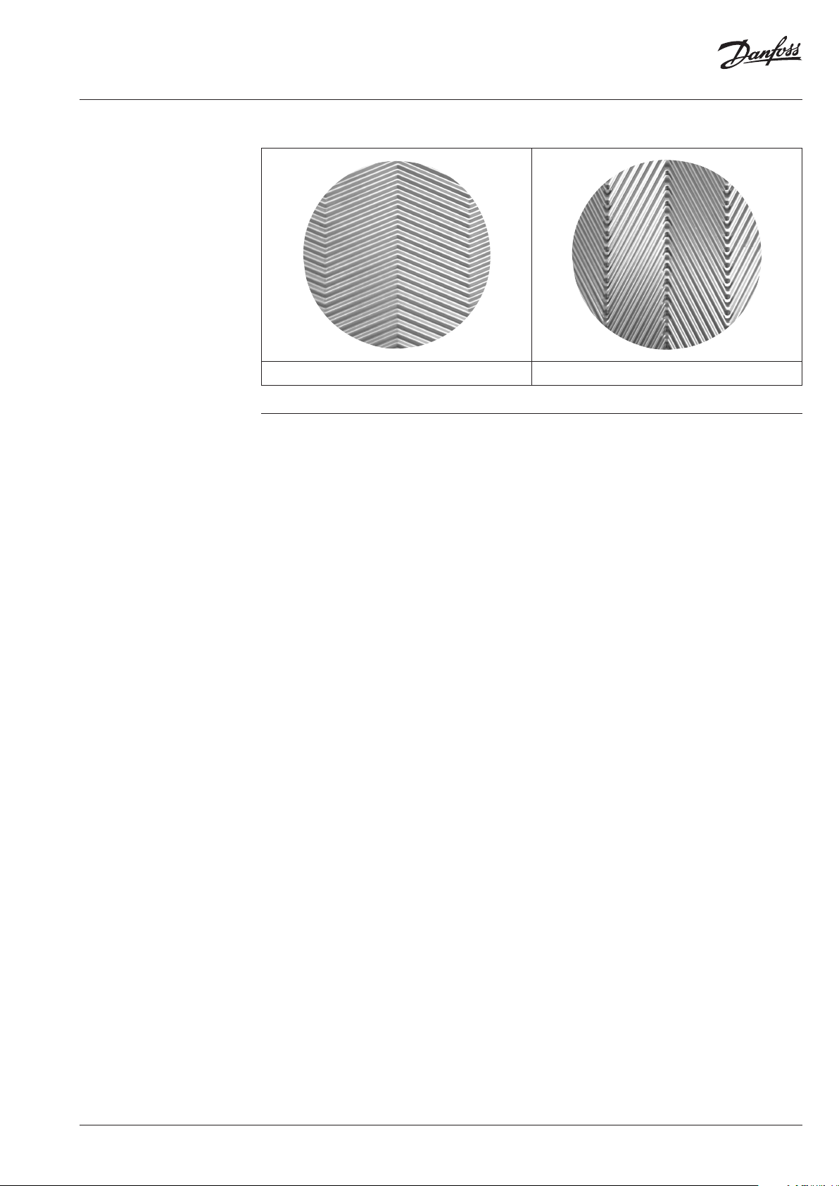
• Check the plate edge pattern for uniformity (see fig. 4, fig 5)
• Identify the A-measure noted prior to opening the heat exchanger (confirm with nameplate)
• Use appropriate tools and lubricant
• Ensure there is no flow to any part of the unit
• Clean the tie bolts and grease the threads
• Install the long tie bolts and tighten evenly
in the numbered order 1, 2, 3, 4 (fig. 5) until a resistance can be noticed. i.e. the follower shall have a
parallel closing motion
• Tighten the long tie bolts in sequence 1 to 4 alternately until the A-measure has been reached at
all long tie bolts
• Tighten the short tie bolts in an alternating order until the A-measure has been reached at all tie
bolts
• Prepare for operation. Follow instructions in section “Start-up process”
• If the heat exchanger does not seal immediately the tie bolts can gradually be tightened to
A-measure minimum (see name plate)
The A-measure shall never be less than A-measure minimum.
Correct stack
Gasket orientation opposing on
last effective plate and end plate.
End
Rotate end plate to suit type of last plate
Figure 4
ench
ft plate
Start plate
Start
n
3
2
If last normal
plate is
“right”...
Tip
Mark plates when servicing
to ensure same order during
reassembly
End plate
to be “left”
Sideview
Incorrect stack
A-measure
3
1
2
4
L
Figure 5
AQ356845617175en-010101 | 13© Danfoss | 2020.10
Page 14

Operating guide Gasketed Heat Exchangers
Regular Service of the plate
heat exchanger
Service sequence – once a year as a minimum
• Check temperatures and flows against commissioning data
• Check general condition and look for any signs of leakage
• Wipe clean all painted parts and check surfaces for signs of damage – “touch up” if necessary.
Check bolts and bars for rust and clean. Coat threaded parts with molybdenum grease or a
corrosion inhibitor (ensure that no grease, etc. falls onto the plate gaskets
• If rollers are fitted to the follower, lubricate the bearings with light machine oil
Years after
commissioning
2 -
3 PHE audit
5
6
7
8
10 Replace
12
13
15
* Ring gasket kit
** Full gasket kit
PHE audit: Visual inspecti on of operating conditions , leaks, corrosion and ge neral condition
Leak detecti on: Pressure test (at least once per year)
CIP: Clean in pla ce (See sectio n “clean in place”)
Manual clea ning: Plate pack disassembly/plate cle aning Replace gaskets: Plate pa ck disassembly/replace gaskets
At extrem e fluids/conditions audits sho uld be performed mo re frequent
Clean fluids/normal conditions Dirty fluids/severe conditions
CIP and
manual
cleaning
Leak
detection
CIP &
manual
cleaning
Leak
detection
CIP &
manual
cleaning
PHE audit
PHE audit
ring- and
main body
gaskets**
PHE audit
Leak
detection
Replace
ring- and
main body
gaskets**
Leak
detection
Leak
detection
Leak
detection
CIP
cleaning
Leak
detection
CIP
cleaning
CIP and
manual
cleaning
CIP
cleaning
-
CIP and
manual
cleaning
- PHE audit
- PHE audit
- PHE audit
PHE audit
PHE audit
Leak
detection
Replace
ring- and
main body
gaskets**
Leak
detection
Replace
ring- and
main body
gaskets**
Leak
detection
Replace
ring
gaskets*
CIP and
manual
cleaning
Replace
ring
gaskets*
CIP &
manual
cleaning
Replace
ring
gaskets*
14 | AQ356845617175en-010101 © Danfoss | 2020.10
Page 15

Operating guide Gasketed Heat Exchangers
Trouble-shooting
Service sequence – once a year as a minimum
Most common problems with a plate heat exchanger, can be solved by own trained personnel. Fig.6
lists a summary of possible problems together with relevant possible causes and solutions.
To maintain a continuous proper function of the plate heat exchanger, it is essential to keep the
operating pressure and temperature within the ranges stated on the nameplate.
Exceeding these values, even as short-lasting peaks, may damage the unit or could be the cause of
problems/issues.
To avoid costly repairs, it is recommended to have the installation and maintenance carried out by
properly trained personnel.
Figure 6
Problem Possible cause Possible solution
Check the rubber liners (if fit ted)
Connection sealing damaged
Leakage
Insufficient capacity
Too high pressure
drop
For nearly all l eakage problems it will be n ecessary to dismantle the uni t before any attempts to rec tify the fault can be made . Mark
the area(s) where the lea kage seems located with a felt tip m arker or similar before dis assembling the plate heat e xchanger. Follow the
instructio ns in section “Openin g the plate heat exchanger ”.
“Cold leakage ” is caused by a sudden change in tem perature. The sealing pr operties of certain e lastomers are temporaril y reduced when
the temperatu re changes suddenly. No actio n is required as the gaskets most of ten re-seal after th e temperature has stabilized .
Mixing of primary and secondary circuit
Plate package sealing damaged
The operating conditions deviate from the specification Adjust the operating conditions
Air in the system
The operating conditions deviate from the specification Adjust the operating conditions
The heat exchanger is fouled internally Clean the heat exchanger
The connections have been interchanged Redo the pipe work
Flow larger than the design flow Adjust the flow
Channels in plates blocked Flush / clean
Incorrect measurement Check the pressure indicator
Fluid deviating from the specification Check the chemical composition
Air in the system
Check the flange gasket (if fit ted)
Check the ring gasket at first plate
Fit the pipes tension-free
Check the plates for holes and/or cracks
Check the diagonal par t of the field gasket
and ring gasket
Check the assembly distance "A"
Check the condition of the gaskets
Check the proper position of the gaskets
Vent the piping system
Check the pipe work for possible air traps
Vent the piping system
Check the pipe work for possible air traps
Gasket failures are generally a result of
• Material aging/degradation
• Excessive exposure to ozone
• High or low operating temperature - outside specified material limits
• Exposure to pressure surges
• Attack by chemicals from medias and/or cleaning agents
• Physical damage from incorrect assembly work
• Misaligned plates (check the hanging system at the top of the plate for distortion)
Decrease in performance is generally a result of
• Plate surfaces require cleaning or de-scaling
• Pumps or associated controls failing
• Plate channels blocked
• Liquid flows not as specified
• Associated boiler under sized or dirty
• Cooling fluid temperature to the plate heat exchanger is higher than the design temperature
• Heating fluid temperature to the plate heat exchanger is lower than the design temperature
• Plate package has been assembled incorrectly
• Plate heat exchanger is running with co-current flow, instead of counter-current. (Check direction
of pump flows)
• Air trap has developed in the plate package or piping work
AQ356845617175en-010101 | 15© Danfoss | 2020.10
Page 16

Operating guide Gasketed Heat Exchangers
After sales service
Scrapping
Ordering parts
When ordering spare parts it is important to provide correct data for:
• Project and order number
• Plate heat exchanger type and manufacturing number (see name plate)
• Required parts
When ordering separate plates it is important that the correct plate code index and type of plate is
given.
When ordering separate gaskets it is important to indicate the correct gasket material.
When ordering tie bolts, the existing bolts should be measured in order to get spare bolts with the
same dimensions.
Modifications to the heat exchanger
Please note that a plate heat exchanger is specific designed and built for the operating parameters
(pressures, temperatures, capacity and type of fluids) initial provided by the customer.
If the plate heat exchanger needs to operate at a different capacity this can be achieved by adding or
removing plates.
Modification of the plate heat exchanger to match other parameters may also be considered. Consult
Danfoss for redesign and/or approval of any change to operating parameters.
After approval by Danfoss a new name plate will be issued.
You may only commission a plate heat exchanger under modified conditions after written approval
by Danfoss.
This product should be dismantled and its components sorted, if possible, in various groups before
recycling or disposal. Always follow the local disposal regulations. For any further information, please
contact your local Danfoss’s representative or your local Danfoss company.
© Danfoss | DHS-SMDBT/SI | 2020.1016 | AQ356845617175en-010101
 Loading...