

Page 1
Data Sheet
Gas detection unit
Accessory
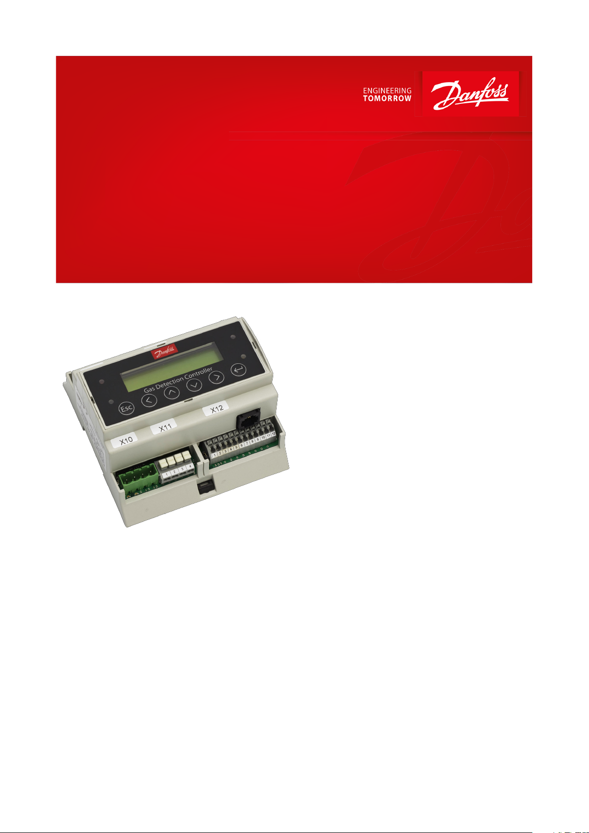
Controller unit
Used for detecting and warning of hazardous gas
concentrations in industrial refrigeration
The gas detection Controller Unit is used for a
centralized monitoring and warning of
hazardous gas concentrations. The input
signals for the controller are collected from the
local gas detection units of the types Basic,
Premium and Heavy Duty via RS485 Fieldbus or
Analog communication. In total 96 gas
detection sensors can be handled via Fieldbus
+ 4 via Analog directly on the controller (+28
additional possible if expansion modules
added).
The Controller Unit comes with 4 alarm relays
available for external looped alarm devices.
Additional relays and sensor wiring loops is
possible by adding Expansion modules to the
controller.
Each local gas detection unit is assigned a
unique address in the Controller and by
continuous communication with the individual
GDU’s the Controller reacts on alarm signals
from the local GDU. The parameter setting and
the actual state of each local GDU can be read
in the Controller display.
AI272548380512en-000202
Page 2

Gas detection unit, Accessory
Features
• For connection of up to 96 sensors via eldbus + 32 via Analog”(when 7 expansion modules added)
• Easy conguration via intuitive user-interface; helps simplify operator handling and minimize risk of operational
setting errors
• Simple commissioning by standard parameter conguration
• Flexible connection to local gas detection units by either Analog or RS485 eldbus communications
• Fieldbus wiring: Wire length up to 900 meters (2953 ft.) per segment
• 4 relays for external alarm device circuits
• Up to 7 Expansion modules possible; allows additional 7 segments with a total of 7200 meters (23622 ft.) wiring
and a total of 32 relays for alarm device circuits
• Automatic self-diagnostics to ensure correct communication and operation
• Relay for communication error
• 6 menu languages
• Password protected settings allowing authorized access only
• Service alerts on display
• Conformity to EN 50545-1
• Enables regulatory compliance with EN 378:2016, ISO 5149:2014
© Danfoss | Climate Solutions | 2022.03 AI272548380512en-000202 | 2
Page 3
Description
Values
Used for product
Basic, Premium and Heavy Duty
Net weight
0.28 kg
Working temperature
-5 °C – 40 °C (23 °F – 104 °F)
Packing format
Single pack
Gas detection unit, Accessory
Portfolio overview
Figure 1: Gas detection Controller unit
Table 1: Portfolio overview
© Danfoss | Climate Solutions | 2022.03 AI272548380512en-000202 | 3
Page 4

Gas detection unit, Accessory
Applications
Detecting and warning of hazardous gas concentrations in industrial refrigeration systems such as food and
beverage processing areas, cold storages, and on-board ships.
© Danfoss | Climate Solutions | 2022.03 AI272548380512en-000202 | 4
Page 5

Gas detection unit, Accessory
Media
Refrigerants
The Danfoss Gas Detection Solution provides a high degree of exibility when designing and building your gas
detection system.
The portfolio ranges from basic to heavy duty models complemented by a range of accessories. The gas detection
units (GDU) can detect a wide range of refrigerant gases including Ammonia (R717), CO2 (R744), uorinated
refrigerants (HCFC and HFCs), and Propane (R290). They come with various sensor technologies to match the
specic refrigerant, application, and safety requirements of the refrigeration system including electrochemical (EC),
semiconductor (SC), Pellistor (P), and infrared sensors.
To provide a strong plug and play solution, all gas detection units come factory precongured to match refrigerant
and typical PPM setting requirements. Depending on national regulations PPM settings may be subject to change.
New refrigerants
Danfoss products are continually evaluated for use with new refrigerants depending on market requirements.
When a refrigerant is approved for use by Danfoss, it is added to the relevant portfolio, and the R number of the
refrigerant (e.g. R513A) will be added to the technical data of the code number. Therefore, products for specic
refrigerants are best checked at store.danfoss.com/en/, or by contacting your local Danfoss representative.
© Danfoss | Climate Solutions | 2022.03 AI272548380512en-000202 | 5
Page 6

Visualization
LCD
Two lines, 16 characters each, illuminated
Status LED (4)
Operation – fault – 1st alarm – ≥ 2nd alarm
Operation
6 push-buttons
Menu language (selectable)
German, English, Dutch, USA, French, Swedish
Interface eldbus
Transceiver
RS 485 / 19200 Baud
Gases
Digital and analog sensors for toxic, combustible & refrigerant gases
Physical
Enclosure
Plastic housing ABS
Colour
RAL 7035
Protection class
IP 40
Weight
0.3 kg (0.8 lb.)
Packaging volumes
Ca. 4.4 l
Mounting
Top DIN rail mounting, installation in distribution box
Dimensions (Controller unit)
(W x H x D) 106 x 110 x 62 mm (4.2 x 4.3 x 2.4 in.)
Dimensions (Controller Solution)
(W x H x D) 298 x 420 x 140 mm (11.7 x 16.5 x 5.5 in.)
Wire connection:
Power supply
Output
Input
Screw type terminal: 2.5 mm2 (14 AWG)
2 x spring type terminal: min. 0.5 mm2, max. 1.5 mm2 (22 to 16 AWG)
Spring type: min. 0.5 mm2, max. 1.5 mm2 (22 to 16 AWG)
Interface ModBus RTU RS 485
Function
Transmission of current and average values, alarm and relay status, and analog
output states in MODBus RTU RS 485 protocol to external devices
Humidity
15 – 95 % RH non-condensing
Working temperature
-5 °C – 40 °C (23 °F to 104 °F)
Storage temperature
0 °C – 40 °C (32 °F to 104 °F)
Gas detection unit, Accessory
Product specication
Design
Table 2: Design
Enviromental conditions
Table 3: Enviromental conditions
© Danfoss | Climate Solutions | 2022.03 AI272548380512en-000202 | 6
Page 7

Digital output
Power/
Main Bus
Controller unit
Relay
AR 01
+-
Main Bus_A
AI_01
AI_02
AI_03
AI_04
AO_01
AO_02
X10
X2X1 X2
X11
X12
D1 D2 D3 D4
7
1
134 10
4 6
2 8
2
14
4
5 11
5 7 8 9 10 11 12
3 9
3
15
3
6 12
< 24 VDC
<
0 VDC
1
24 VDC
24 VDC
0 VDC
0 VDC
Main Bus_A
Field Bus_A
Main Bus_B
Field Bus_B
2
A
Power Analog
output
AP01 AP02 AP03 AP04
4-20 mA
24 VDC
1 2 3 4
Analog
input
B
Relay
AR 02
Relay
AR 03
Relay
AR 04
Main Bus_B
24 VDC
0 VDC
4-20 mA
24 VDC
4-20 mA
24 VDC
4-20 mA
24 VDC
Danfoss
148H144
31 52
X_Bus
X_Bus
0 VDC
Relay
DRF
Relay
Fault
Field Bus_A
Field Bus_B
Digital
input
Field Bus
DI_01
DI_02
DI_03
DI_04
Electrical
Description
Power supply
24 V DC ± 20 %
Power consumption (24 V DC)
4 W, 150 mA
Analog input (4)
4 – 20 mA, overload and short-circuit- protected, input resistance 200 Ω
Tension for external analog transmitter
24 V DC (same as power supply), max. 100 mA / per sensor
Analog output (2) congurable for each input
Proportional, overload and short-circuit- protected, charge ≤ 500 Ω
4 – 20 mA = measuring range
3.0 < 4 mA = underrange
>20 – 21.2 mA = overrange
2.0 mA = fault
Alarm relay (4)
250 V AC, 5 A, potential-free, change-over (SPDT)
Fault relay (1)
250 V AC, 5 A, potential-free, normally open contact (SPST)
Gas detection unit, Accessory
Electrical connection
Figure 2: Circuit connection
NOTE:
RJ45 port available on the controller.
Table 4: Electrical connection
Fieldbus loop
Each GD controller can handle up to 96 sensors and handle any mix of individual Gas detection units of the types
Basic, Premium and Heavy Duty.
The max. recommended loop wire length is 900 meter (2953 ft) per segment.
With additional segments (and additional controller expansion modules) the max recommended loop wire length is
7200 meter (23622 ft).
The controller and the last GDU in each segment must be provided with a resistor of 560 Ohm. A Umin of 16 V DC
must be secured at any spot in the loop.
Below gure shows how to make proper connections between the controller and each GDU.
© Danfoss | Climate Solutions | 2022.03 AI272548380512en-000202 | 7
Page 8

GDU Addr. 05 GDU Addr. 04
560 R
Controller Unit
0 V DC
24 V DC
BUS_B
BUS_A
0 V DC
24 V DC
4
3
2
1
4
3
2
1
4
3
2
1
4
3
2
1
4
3
2
1
U
min
= 16 V DC
GDU Addr. 01 GDU Addr. 02 GDU Addr. 03
Danfoss
148H139
GDU Addr. 05 GDU Addr. 04
GDU Addr. 01 GDU Addr. 02 GDU Addr. 03
Controller
unit
= Terminatingresistor 560 OhmR
R
R
= GDU (Basic, Premium and/or Heavy Duty)
R
R
RIGHT
WRONG
Controller
unit
Controller
unit
Wire length max. 900 meter (2953 ft) per segment.
More segments with additional expansion modules max. 7200 meter (23622 ft).
Additional power limitations must be calculated.
Danfoss
148H123
Gas detection unit, Accessory
Figure 3: Controller unit conections
Figure 4: Connections between the controller and each GDU
© Danfoss | Climate Solutions | 2022.03 AI272548380512en-000202 | 8
Page 9

Description
Code number
Controller unit
148H6231
Controller solution (controller + enclosure)
148H6221
Controller solution Uptime
148H6237
Warning module (wire break monitoring module)
148H6223
Controller expansion module
148H6222
Gateway for controller
148H6228
Gas detection unit, Accessory
Ordering
Table 5: Ordering
Controller solution
Controller unit placed in an enclosure ready to be connected to a power source. A separate uptime solution with
UPS for the controller is available.
Warning module (wire break monitoring module)
The warning module is used for monitoring the circuiting to the warning/alarm devices on a centrally controlled gas
detection system. Wire breaks or wire interruptions in the alarm device loop will be reported to the central control.
Controller expansion module
The gas detection Controller Expansion module is used for expansion of the cable coverage in terms of number of
loops and the total wire length. Each Controller Unit can handle up to 7 Expansion modules allowing additional 7
segments with a total of 7200 meters (23622 ft.) wiring and a total of 32 relays for alarm device circuits.
Gateway for controller
The gateway is an addition to the controller and used for communicating via Modbus TCP/IP.
© Danfoss | Climate Solutions | 2022.03 AI272548380512en-000202 | 9
Page 10

EMC – Directive 2014/30/EU
Low voltage directive 2014/35/EU
EN 50545-1, EN 50271
Gas detection unit, Accessory
Certicates, declarations, and approvals
The list contains all certicates, declarations, and approvals for this product type. Individual code number may have
some or all of these approvals, and certain local approvals may not appear on the list.
Some approvals may change over time. You can check the most current status at danfoss.com or contact your local
Danfoss representative if you have any questions.
Table 6: Compliance table
© Danfoss | Climate Solutions | 2022.03 AI272548380512en-000202 | 10
Page 11

Online support
Danfoss oers a wide range of support along with our products, including digital product information, software,
mobile apps, and expert guidance. See the possibilities below.
The Danfoss Product Store
The Danfoss Product Store is your one-stop shop for everything product related—no matter where
you are in the world or what area of the cooling industry you work in. Get quick access to essential
information like product specs, code numbers, technical documentation, certications, accessories,
and more.
Start browsing at store.danfoss.com.
Find technical documentation
Find the technical documentation you need to get your project up and running. Get direct access to
our ocial collection of data sheets, certicates and declarations, manuals and guides, 3D models
and drawings, case stories, brochures, and much more.
Start searching now at www.danfoss.com/en/service-and-support/documentation.
Danfoss Learning
Danfoss Learning is a free online learning platform. It features courses and materials specically
designed to help engineers, installers, service technicians, and wholesalers better understand the
products, applications, industry topics, and trends that will help you do your job better.
Create your Danfoss Learning account for free at www.danfoss.com/en/service-and-support/learning.
Get local information and support
Local Danfoss websites are the main sources for help and information about our company and
products. Find product availability, get the latest regional news, or connect with a nearby expert—all
in your own language.
Find your local Danfoss website here: www.danfoss.com/en/choose-region.
Spare Parts
Get access to the Danfoss spare parts and service kit catalog right from your smartphone. The app
contains a wide range of components for air conditioning and refrigeration applications, such as
valves, strainers, pressure switches, and sensors.
Download the Spare Parts app for free at www.danfoss.com/en/service-and-support/downloads.
Any information, including, but not limited to information on selection of product, its application or use, product design, weight, dimensions, capacity or any other
technical data in product manuals, catalogues descriptions, advertisements, etc. and whether made available in writing, orally, electronically, online or via download,
shall be considered informative, and is only binding if and to the extent, explicit reference is made in a quotation or order conrmation. Danfoss cannot accept any
responsibility for possible errors in catalogues, brochures, videos and other material. Danfoss reserves the right to alter its products without notice. This also applies to
products ordered but not delivered provided that such alterations can be made without changes to form, t or function of the product. All trademarks in this material
are property of Danfoss A/S or Danfoss group companies. Danfoss and the Danfoss logo are trademarks of Danfoss A/S. All rights reserved.
© Danfoss | Climate Solutions | 2022.03 AI272548380512en-000202 | 11
 Loading...