

Page 1
Installation Guide
Danfoss
148H151_02-2018
X10
X11
X12
1
46
2
4
578910 11 12
3
3
12
Danfoss
Danf
148H149_02-2018
X12
Flash ligh
X11
Danf
148H150_02-2018
Danf
148H153_02-2018
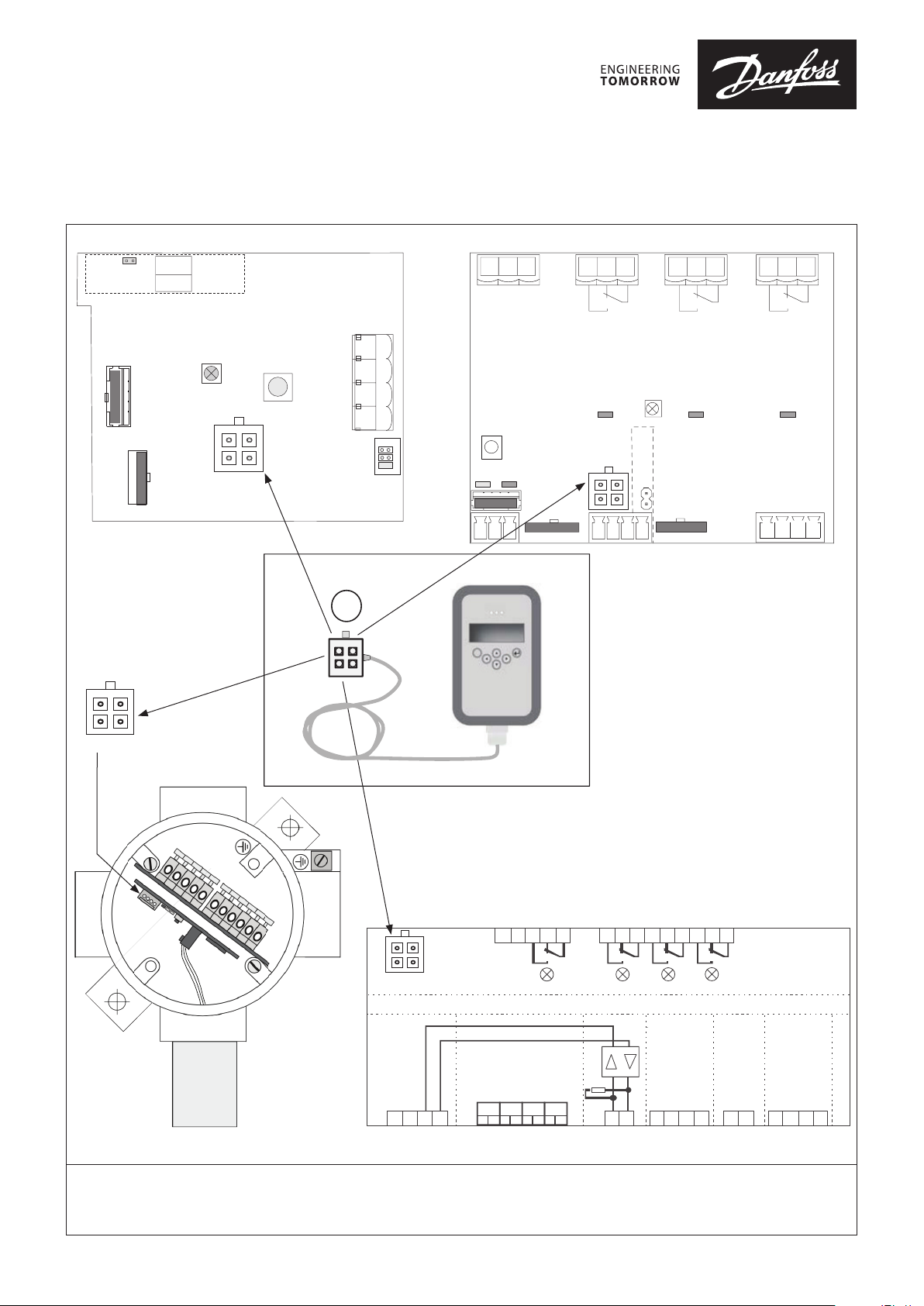
Gas detection Service Tool for configuration of Basic, Premium,
Heavy Duty and Controller expansion modules
Basic Premium
JP4*
Open: 4-20mA
Closed: 2-10V AO_01
148R9639
X8
5
GND
4
Analog Output
X1
Status LED
Green/Yellow/Red
X2
o
o
o
o
X9
Service Tool
Ackn. -/Test
button T1
1
23
NC
GND
24 V DC
3
X4
12 4
Jumper
J1
J2
J3
oss
Ackn./Test
button
Power Bus Comm.
2
3
1
3
2
Relay status
LED Green
Service Tool
o
o
1
Green/Yellow/Red
o
o
321
X1
X2
Status LED
open: 4-20mA
closed: 2-10 V
JP2*
4
3
2
Relay status
LED Green
132
X3
Relay status
LED Green
Digital
Output
NC
X13
GND
Horn
567
1
X4
t
148R9639
oss
o
o
o
o
Adapter
Service
Tool
Sensor
1
oss
148H148_02-2018
o
o
Service Tool
Power/
Main Bus
+
o
o
F_Bus_A
-
X2X1 X2
28
39
Field Bus
F_Bus_B
< 24 VDC
1
0 VDC
2 3 4
511
D1 D2 D3 D4
Power
24 VDC
<
7
612
Digital output
Expansion Module
Analog
input
560 R
0 VDC
AI_01
AI_02
13410
AI_03
14
AI_04
15
Analog
output
AO_03
AO_04
Heavy Duty Controller expansion module
1. Plug-in Service tool plug
2. Await Display light
3. Follow instructions in User Guide DKRCI.PS.S00.B1.02
© Danfoss | DCS (MWA) | 2018.02
DKRCI.PI.S00.L1.02 | 520H12756 | 1
Page 2

ENGLISH
Software features:
• Addressing of the Basic, Premium and Heavy Duty devices
• Calibration of the Basic, Premium and Heavy Duty devices
• Configuration of application parameters of the Basic, Premium
and Heavy Duty devices
• Monitoring of all measuring values at a glance, live
To access the user guide please go to further documentation.
© Danfoss | DCS (MWA) | 2018.02
Further documentation:
DKRCI.PI.S00.L1.02 | 520H12756 | 2
 Loading...