

Page 1
Application Guide
Gas detection in
refrigeration systems
GDIR.danfoss.com
Page 2

Page 3

Application Guide | Gas detection in refrigeration systems
Contents Page
Commonly used abbreviations......................................................................3
Introduction........................................................................................4
Sensor technology..................................................................................4
EC - Electrochemical sensor .....................................................................4
SC - Semiconductor sensor (solid state)..........................................................5
P- Pellistor sensor...............................................................................6
IR - Infrared.....................................................................................6
Which sensor is suitable to a given refrigerant? ..................................................6
Sensor response time ...............................................................................7
The need for gas detection..........................................................................8
Legislation and standards...........................................................................8
Requirements for gas detection according to EN 378:2016 and ISO 5149:2014 ....................9
F-Gas legislation.............................................................................. 10
Requirements for gas detection according to ASHRAE 15-2016 (USA)........................... 10
Requirements for gas detection according to ANSI/IIAR-2 (USA) ................................ 10
Installation guideline ............................................................................. 11
Location of gas detectors ......................................................................... 12
Number of gas detectors in a facility............................................................... 13
Calibration / test.................................................................................. 13
Calibration methods ..............................................................................14
Method I Calibration by means of replacing sensor heads...................................... 14
Method II Calibration of gas detectors by means of calibration gas .............................14
Bump test ....................................................................................15
Alarm / sensitivity range gas detectors ........................................................ 16
Danfoss recommendations for alarm levels.................................................... 16
Actions triggered by gas detection ...............................................................18
References .......................................................................................19
Annex I - Common refrigerant data................................................................ 20
Annex II - EN 378:2016 and ISO 5149:2014 ......................................................... 20
Annex III - ASHRAE 15-2016 ....................................................................... 21
Commonly used
abbreviations
© Danfoss | DCS (mwa) | 2018.08
• LFL = Lower Flammability Level
• OEL = Occupational Exposure Limits
• ATEL = Acute-Toxicity Exposure Limit
• ODL = Oxygen Deprivation Limit
• OSH = Occupational Safety Limit
• ODP = Ozone Depletion Potential
• GWP = Global Warming Potential
• TRK = Technische Richtkonzentrationen
• MAK = Maximale Arbeitsplatzkonzentrationen
• TLV = Threshold Limit Value
• STEL = Short Term Exposure Limit
• PEL = Permissible Exposure Limits
DKRCI.PA.S00.A2.02 | 520H12772 | 3
Page 4
Application Guide | Gas detection in refrigeration systems
e
Sensitivity
Introduction Gas detection and leak detection are two distinct
activities that covers the same topic, but the
methods are very different.
Gas detection covers the analysis of air samples
to determine whether they contain refrigerant
gas. Leak detection is a systematic inspection
of a refrigeration system to determine whether
it is leaking. The terms gas detection and leak
detection are not interchangeable, and must not
be mixed.
Leak detection equipment is normally handheld equipment carried by people, and used for
detection of leaks in refrigeration systems. There
are several types of leak detectors available,
ranging from simple techniques like soapy water
to sophisticated electrical instruments.
Gas detection equipment is usually used in
a fixed installation with a number of sensors
located in areas where refrigerant might be
expected to accumulate in the event of a plant
leak.
Sensor technology The choice of sensor technology for refrigerant
gas detection will depend on the specific target
refrigerant gas and ppm range required. Danfoss
offers a range of different sensor technologies
These locations depend upon the layout of
the machinery room and adjacent spaces, on
the configuration of the plant and also on the
refrigerant in question.
Before selecting the appropriate gas detection
equipment, a number of questions have to be
answered:
• Which gases have to be measured and in what
quantities?
– Which sensor principle is the most suitable?
– How many sensors are needed?
– Where and how should they be positioned
and calibrated?
• Which alarm limits are appropriate?
– How many are required?
– How is the alarm information processed?
This application guide will address these
questions.
to match most commonly used refrigerants,
appropriate ppm ranges, and safety requirements
for refrigeration systems.
EC - Electrochemical sensor Electrochemical sensors are mainly used for toxic
gases and are suitable for ammonia.
They consist of two electrodes immersed in an
electrolyte medium.
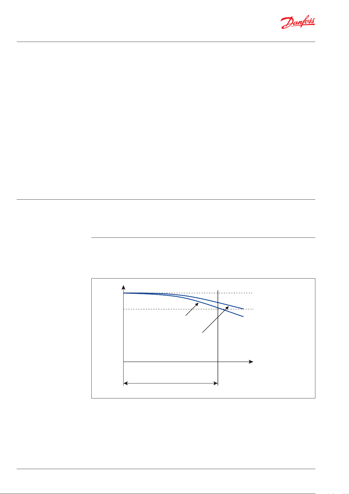
“High” gas concentration
“Low” gas concentration
Max. operating time
before calibration
Fig. 1: Sensitivity of electrochemical sensors
They are very accurate (+/- 2%) and tend to be
used mainly for toxic gases, which cannot be
detected otherwise, or where high levels of
accuracy are needed (fig. 1).
An oxidation / reduction reaction generates an
electric current that is proportional to the gas
concentration.
max.
Tolerance rang
min.
Time
Exposure to large ammonia leaks or constant
background ammonia will shorten the sensor life
(fig. 2). EC sensors can be re-calibrated as long as
the sensitivity of the sensor is above 30%.
4 | DKRCI.PA.S00.A2.02 | 520H12772
Danfoss offers specific EC sensors for ammonia
in ranges up to 0-5.000 ppm with an expected
lifetime of 2 years, depending on exposure to
target gas.
They are very selective and rarely subject to
cross-interference. They may react to sudden
large humidity changes but settle quickly.
© Danfoss | DCS (mwa) | 2018.08
Page 5
Application Guide | Gas detection in refrigeration systems
e
Sensitivity
Gas specification
Sensitivity
EC - Electrochemical sensor
(continued)
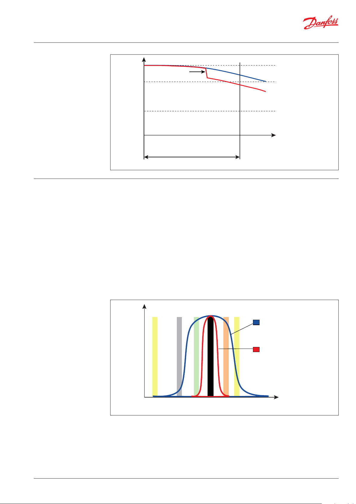
“Substantial”
gas leak
Important!
Sensor must be calibrated or new
sensor must be installed.
max.
Tolerance rang
min.
SC - Semiconductor sensor
(solid state)
If the sensitivity of the sensor falls
below 30%; install new sensor
Max. operating time
before calibration
Fig. 2: Large ammonia exposure shortens the lifetime of electrochemical sensors.
The semi-conductor sensor functions by
measuring the resistance change (proportional to
the concentration), as gas is absorbed on to the
surface of a semi-conductor, which is normally
However, they are not selective, and are not
suitable for detecting a single gas in a mixture, or
for use where high concentrations of interfering
gases are likely to be present (fig. 3).
made from metal oxides.
Interference from short term sources (e.g.
These can be used for a wide range of gases
including combustible, toxic and refrigerant
gases.
It is claimed that they perform better than the
catalytic type in the detection of combustible
gases at low concentrations, up to 1.000 ppm.
exhaust gas from a truck), creating false alarms,
can be overcome by enabling a delay of the
alarm.
Semi-conductors for halocarbons can be used
to detect more than one gas or a mixture
simultaneously. This is particularly useful in
monitoring a plant room with several different
These are low-cost, long life, sensitive and can be
refrigerants.
used to detect a large range of gases including
all the HCFC, HFC refrigerants, ammonia and
hydrocarbons.
30% sensitivity
Time
“Broad” sensitivity
spectrum
– Semiconductor
– Pellistor
“Narrow” sensitivity
Gas 1
Fig. 3: Sensitivity spectrum of various sensor technologies
Gas 2
Gas 3
Gas 4
Gas 5
Target Gas
© Danfoss | DCS (mwa) | 2018.08
spectrum
– Electrochemical
– Infrared
DKRCI.PA.S00.A2.02 | 520H12772 | 5
Page 6
Application Guide | Gas detection in refrigeration systems
P- Pellistor sensor Pellistors (sometimes called a bead or catalytic)
are mainly used for combustible gases including
ammonia, and are the most popular sensors for
this application at high detection levels.
The sensor functions by burning the gas at
the surface of the bead and measuring the
resultant resistance change in the bead (which is
proportional to concentration).
These are relatively low-cost, well established
and understood, and they have a good life span
(expected life time 3 to 5 years). The response
time is usually below 10 seconds.
They can be subject to poisoning in certain
applications.
IR - Infrared Infrared technology utilises the fact that most
gases have a characteristic absorption band in
the infrared region of the spectrum, and this
can be used to detect them. Comparison with a
reference beam allows the concentration to be
determined.
Even though they are relatively expensive in
comparison to other sensor, they have long life
time of up to 15 years, high accuracy, and low
cross sensitivity
Poisoning is the reduction of the reaction of the
sensor to the target gas due to the presence
(contamination) of another substance on the
surface of the catalyst, that either reacts with it or
forms a layer on top of it reducing its capacity to
react to the target gas. Most common poisoning
substances are silicon compounds.
Pellistors are used mainly with combustible gases
and are therefore suited for ammonia and the
hydrocarbon refrigerants at high concentrations.
They do sense all combustible gases, but they
respond at different rates to each, and so they
can be calibrated for particular gases.
There are ammonia specific versions.
Due to its measuring principle infrared sensors
can be subject to issues in dusty environments,
where the presence of too many particles in the
air may disturb the reading.
They are recommended and commonly used for
Carbon dioxide detection. Although technology
exists for other gases also, it is not common to
find it in commercial solutions.
Which sensor is suitable to a
given refrigerant?
Based on the target refrigerant gas and the
actual ppm range the below table provides an
overview of the suitability of the various sensor
technologies offered by Danfoss.
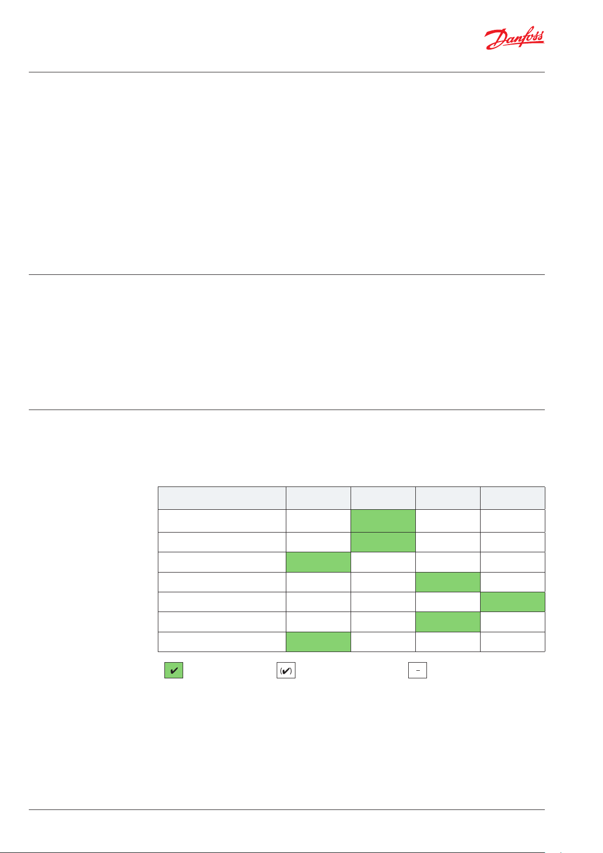
Suitability of different sensor technologies:
Semi-conducter Electro-chemical
Ammonia “low” concentration
(< 100 ppm)
Ammonia “medium” concentration
(< 1000 ppm) 1)
Ammonia “high” concentration
(<10000 ppm)
Ammonia “very high” concentration
(> 10000 ppm)
Carbon Dioxide
CO₂
HC
Hydrocarbons
HCFC - HFC
Halocarbons
Best solution
1
) Measuring range 0-1000 ppm. Can be adjusted in the whole range.
2
) Up to 5000 ppm. For specific applications.
–
(4) 4
4 (4)
– –
– – –
– –
4
Suitable - but less attractive Not suitable
Pellistor
(Catalytic)
4
2
– – –
– –
– –
(4)
4
4
Infrared
–
–
4
–
6 | DKRCI.PA.S00.A2.02 | 520H12772
© Danfoss | DCS (mwa) | 2018.08
Page 7
Application Guide | Gas detection in refrigeration systems
1
Time, s
Fraction of Concentration Change
250
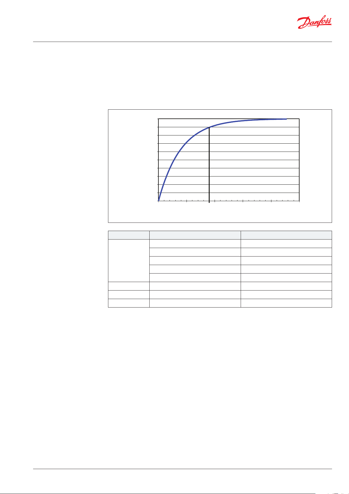
Sensor response time
The response time is the elapsed time for a sensor
to read a given percentage of the actual value for
a step change in the target gas concentrations.
Response time for most sensors is given as t90,
meaning the time that it takes the sensor to read
90% of the actual concentration. Fig. 4 shows an
example of a sensor with a reponse time t90 of 90
seconds.
0.9
0.8
0.7
0.6
0.5
0.4
0.3
0.2
0.1
0
050 100 150 200
Fig. 4: Sensor with a response time t90 of 90 seconds
As shown in the graphic, the sensor reaction
above 90% becomes slower and takes longer to
read the 100%.
GAS Sensor technology Response time t90, seconds
Electrochemical 0-100/ 0-300 ppm <40s
Electrochemical 0-1000ppm <40s
Ammonia
Electrochemical 0-5000ppm <40s
Semiconductor >120s
Pellistor <20s
Infrared Infrared <90s
Halocarbons Semiconductor >120s
Hydrocarbons Pellistor <15s
© Danfoss | DCS (mwa) | 2018.08
DKRCI.PA.S00.A2.02 | 520H12772 | 7
Page 8

Application Guide | Gas detection in refrigeration systems
The need for gas detection
There are several reasons why gas detection
is required. Two obvious reasons are to protect
people, production and equipment from the
impact of potential gas leakages and to comply
with regulations. Other good reasons include:
• Reduced service cost (cost of replacement gas
and the service call).
• Reduced energy consumption cost due to lack
of refrigerant.
• Risk for damaging stock products due to a
substantial leak.
• Possibility to reduce insurance costs.
• Taxes or quota on non-environmentally
friendly refrigerants
The various refrigeration applications require gas
detection for different reasons.
Ammonia is classified as a toxic substance with
a very unique smell, as such it is “self alarming”.
However, gas detectors are required to guarantee
early warnings, and to monitor areas where
people are not always present, such as machinery
rooms. It is important to be aware that ammonia
is the only common refrigerant lighter than air.
In many cases, this will lead to ammonia rising
above the breathing zone making it impossible
for people to early detect ammonia leakages. The
use of gas detectors in the right zones ensures
early warnings in case of ammonia leakages.
Hydrocarbons are classified as flammable. Thus,
it’s critical to verify that the concentration around
the refrigeration system does not exceed the
flammability limit.
Fluorinated refrigerants all have a certain
negative impact on the environment, for which
reason it’s very important to avoid any leaks.
CO2 (Carbon Dioxide) is directly involved in
the respiration process and should be treated
accordingly. Approximately 0.04% CO2 is
present in the air. With higher concentration,
some adverse reactions are reported starting
with increase in breath rate (~100% at 3%
CO2 concentration) and leading to loss of
consciousness and death at CO2 concentrations
above 10%.
Legislation and standards The requirements for gas detection are different
across countries worldwide. An overview of the
most common rules and regulation can be found
on the following pages.
Europe:
The present safety standard for refrigeration
systems in Europe is EN 378:2016.
The specified alarm levels in EN 378:2016 are set
at levels to allow evacuation of an area. The levels
do not reflect the effects of long term exposure
to leaked refrigerants. In other words, in EN 378
a gas detector is to warn when a sudden large
release occurs, while machine room ventilation
and system quality measures are to ensure that
small leaks are too small to cause adverse health
effects.
Note!
Requirements for gas detection
equipment in Europe are covered by
national legislation in the different
countries, and consequently may differ
from the requirements specified in EN
378.
8 | DKRCI.PA.S00.A2.02 | 520H12772
© Danfoss | DCS (mwa) | 2018.08
Page 9

Application Guide | Gas detection in refrigeration systems
Requirements for gas detection
according to EN 378:2016 and
ISO 5149:2014
Start
Y
Y
Gas detector
used to start fan or
close valves
Y
Gas detector
required
Y
Y
Below ground
2
in machinery room
or open air
Gas detector
required
N
N
Ammonia
Y
Charge >
50 kg
Y
Gas detection
required
high/low level
using alternative risk
Y
Charge limits
for ventilated
enclosure
N
Charge limits
management
N
Charge >
100% practical
limit
N
Using EN 378
and charge >m
and A3 or B3
N
Fig. 5: Requirements for gas detection according to EN 378:2016 part 3 and ISO 5149:2014 part 3
With a few exceptions gas detection is required
by EN 378:2016 and ISO 5149:2014 for all
installations where the concentration in a room
may exceed the practical limit for that space.
The practical limits for various refrigerants are
given in Annex II, which are extracted from EN
378-2016 part 1. In these tables the practical
limit of ammonia is based upon its toxicity. The
practical limits of the hydrocarbons are based
In the case of flammable and toxic refrigerants
this means virtually all commercial and industrial
systems In the case of A1 refrigerants it is possible
to have small systems, which do not require gas
upon their flammability and are set at 20% of
their lower flammable limit. The practical limits
for all the A1 refrigerants are set at their Acute
Toxicity Exposure Limit (ATEL).
detection. However, in most of the larger plants
it is likely that the practical limit will be exceeded
in the event of a major leak, and therefore gas
detection is required.
If the total refrigerant charge in a room, divided
by the net room volume, is greater than the
“practical limit” (see Annex II), it is reasonable to
conclude that fixed gas detection system should
Guidance can be found in EN 378:2016 part
be installed.
3 or ISO 5149:2014 part 3. The requirements
of the two standards are very similar, and are
summarised in fig. 5.
Both EN378:2016 and ISO 5149:2014 require that
an indicating device is provided to show whether
the relief valve has discharged on systems with
If it can be shown by calculation that the
concentration of refrigerant in a room can never
300 kg refrigerants or more. A possibility is to
place a gas detector in the discharge line.
reach the practical limit; then there is no need for
fixed gas detection, except according to EN 378 if
the system is below ground with a charge above
m2 (approx. 1 kg of propane). ISO 5149 does not
have this exception. m2 is a constant equal to
26m3 x LFL. For propane it is 26 m3 x 0,038 kg/m3
= 0,988 kg, or, if your LFL is measured in gram, it is
26 m3 x 38g/m3 =988 g. As such m2 does not have
any units, since the units depend solely on which
unit you chose for LFL.
Most hydrocarbons have similar value of LFL, and
m2 is therefore typically around 1kg.
N
N
No requirements
© Danfoss | DCS (mwa) | 2018.08
However, if the concentration can reach the
practical limit, even for A1 refrigerants, then fixed
detection must be installed - again with a few
minor exceptions.
DKRCI.PA.S00.A2.02 | 520H12772 | 9
Page 10

Application Guide | Gas detection in refrigeration systems
(Clause 7.2)
(Clause 8.11.2.1)
(Clause 7.2)
(Clause 7.2.2)
F-Gas legislation The F-Gas Regulation (EC) No 517/2014
One objective of the F-Gas Regulation is to
contain, prevent and thereby reduce emissions
of fluorinated greenhouse gases covered by the
Kyoto Protocol. The F-gas directive is mandatory
in all EU member countries and in the three
European Economic Area (EEA) EFTA countries
including Iceland, Liechtenstein, and Norway.
The regulation covers, among other topics, the
import, export and use of the traditional HFCs
and PFCs in all their applications. The regulation
entered into force on January 1st, 2015.
Leakage checking requirements, to prevent
leakage and to repair any detected leakage,
depends on the CO2 equivalents of the refrigerant
in each circuit with refrigerant. The CO2
equivalents is the charge in kg x the GWP of the
refrigerant.
Requirements for gas detection
according to ASHRAE 15-2016
(USA)
Requirements for gas detection according
to ASHRAE 15-2016 state requirements for
rooms with refrigerating equipment including
machinery rooms. The “Low Level” alarm values
are less or equal to TLV-TWA levels.
A periodical leakage check by certified personnel
is required with the following frequency,
depending on the quantity used:
• 5 tCO
or more: At least once every 12 months
2eq
– except for hermetically sealed systems
containing less than 10 tCO
• 50 tCO
or more: At least once every 6 months
2eq
2eq
(12 months with an appropriate leakage
detection system)
• 500 tCO
or more: At least once every 6
2eq
months. An appropriate leakage detection
system is mandatory. The leakage detection
system must be checked at least once every 12
months.
In practice, the Occupational Exposure Limit
(OEL) values from ASHRAE 34 are used since they
are based on TLV-TWA (see also “Occupational
Exposure Limits”, page 18)
Start
Requirements for gas detection
according to ANSI/IIAR-2 (USA)
Y
Y
N
No requirements
Gas detection
required
No requirements
Gas detection
required
Charge < 3 kg
N
Machinery
room
N
Charge >
RCL
N
Y
Additional
requirements
Fig. 6: Gas detection requirements according to ASHRAE 15-2016.
* Note 1: The charge limit stated in ASHRAE 15-2016 can also be found in Annex II (RCL) - for selected refrigerants.
Note 2: ASHRAE 15 does not include Ammonia. Refer to ANSI/IIAR-2.
ANSI/IIAR -2 requires machinery rooms to be
provided with ammonia gas detectors. It requires
3 different alarm levels (25, 150 and 40000 ppm)
with different response requirements according
to each of the levels.
10 | DKRCI.PA.S00.A2.02 | 520H12772
Start
Gas detector required
Alarm at 25, 150,
and 40000 ppm (max)
Y N
Machine room
Fig. 7: Gas detection requirements according to the ANSI/IIAR-2
Gas detector required
Alarm at 25 ppm
© Danfoss | DCS (mwa) | 2018.08
Page 11

Application Guide | Gas detection in refrigeration systems
Relative density
0
1
2
3
4
Installation guideline When it comes to installation of gas detection
there are two approaches:
• Perimeter detection
• Point detection
With perimeter detection, you place sensors all
around the perimeter of the space in question, to
make sure you monitor the whole space.
With point detection, you locate a sensor at a
particular position, where you are concerned
about a leak (e.g. at the compressor).
For gases heavier than air, sensors should be
located close to the ground/lowest point.
For gases lighter than air, sensors should be
mounted high up on the walls, ceiling or near
exhaust, but convenient for maintenance.
If the density is equal to air, the sensors should be
mounted at face level.
In some countries it may be mandatory to
have an UPS (Uninterruptible Power Supply)
connected to the gas detectors to ensure safe
operation during a power failure.
(refrigerant/air)
Fig. 8: Relative density refrigerant/air
© Danfoss | DCS (mwa) | 2018.08
DKRCI.PA.S00.A2.02 | 520H12772 | 11
Page 12

Application Guide | Gas detection in refrigeration systems
Location of gas detectors Gas detectors must be powered as specified in
the installation guide and located within the
specified cable length from the central control
unit/monitor.
In general:
• Do not mount to a structure that is subject to
vibration and shock, such as piping and piping
supports.
• Do not locate near excessive heat or in wet or
damp locations.
The two methods of locating sensors:
• Point detection: Sensors are located as near as
possible to the most likely sources of leakage.
• Perimeter detection: Sensors surround the
hazardous area completely.
• Do not mount where it will be exposed to
direct solar heating.
• Do not install in areas where condensation may
form.
The most appropriate method is selected
depending on the size and nature of the site.
• Detectors shall be located high/low according
to the density of the actual refrigerant.
• If mechanical ventilation exists in a machinery
room, air will move towards the fan. In
problematic locations a smoke tube can
indicate air movements in a space and assist in
the location of sensors.
• In a cold store, sensors should, if possible, be
placed on the wall in the return airflow.
• Consideration should also be given to the
possibility of pockets of gas collecting in the
event of a leak.
The arrangement of the equipment in the room
can also have an impact on the most effective
place to monitor.
Locations requiring most protection in a
machinery or plant room would be around gas
boilers, compressors, pressurized storage tanks,
gas cylinders, storage rooms, or pipelines.
Most vulnerable are valves, gauges, flanges,
T-joints, filling or draining connections etc.
Sensors should be positioned a little way back
from any high-pressure parts to allow gas clouds
to form. Otherwise any leakage of gas is likely
to pass by in a high-speed jet and will not be
detected by the sensor.
Important!
Do not place immediately in front of a
coil due to temperature and humidity
fluctuations. These may occur especially
during defrost or loading of a cold store.
Make sure that pits, stairwells and
trenches are monitored since they
may fill with stagnant pockets of gas.
Monitoring where leaked refrigerant
can stagnate is generally required by
standards.
As general guideline:
• If there is one compressor/chiller in the room;
sample at the perimeter of the unit. For two
chillers; sample between them, with three or
more chillers; sample between and on each
side. Ensure that the area being sampled
is sufficiently monitored. Do not skimp on
sensors.
• Place the sensor in the location(s) most likely to
develop a gas leak, including mechanical joints,
seals, and where there are regular changes
in the system’s temperature and pressure or
excessive vibration, such as compressors and
evaporator control valves.
Accessibility and space to allow calibration and
service must be considered.
12 | DKRCI.PA.S00.A2.02 | 520H12772
© Danfoss | DCS (mwa) | 2018.08
Page 13

Application Guide | Gas detection in refrigeration systems
Number of gas detectors
in a facility
The requirements for the number of gas detectors
in a facility are not specifically stated in standards.
As general guideline:
• A gas detector can normally cover an area of
about 50-100 m2 depending on the actual
condition of the space to be covered. In
spaces with several obstructions and lack
of ventilation the coverage is approx. 50 m2,
provided it is mounted near ceiling level or
near floor level depending on the refrigerant
density.
In non-obstructed spaces with good
mechanical ventilation, the coverage can be
increased up to approx. 100 m2.
• Machinery rooms:
It is recommended that gasdetectors are
placed above or at both sides of compressors
or other non-static parts of the system
or down wind of such equipment, in the
direction of continuously operating ventilation
extractors.
Where there are deep beams and lighter than
air refrigerants, it is recommended that the
detectors are mounted between pairs of beams
and on the underside of the beams.
Calibration / test Calibration/test of gas detectors is extremely
important to ensure and document the proper
accuracy, responsiveness and operation of the
unit.
If there is a continuous airflow in the
room a sensor/sensing point should
be located downstream from the last
potential leak source.
From a technically and safety point of view, the
sensors offered by Danfoss should be calibrated/
tested according to the stated intervals in the
table below.
Gas detectors are subject to changes in the
measurement properties, dependent on the
operation time and/or exposure time. Therefore,
regular calibration is needed. The frequency
depends on various factors, however the
IMPORTANT!
If national legislation requires
calibration/test with intervals shorter
(stricter) than stated in the table below,
these requirements must be followed.
following four are of particular importance:
• Requirements of national legislation
• Recommended calibration interval
Note: EN 378:2016 and ISO 5149 require gas
detectors to be checked on an annual basis.
• Lifetime of the sensors
• The lifetime and calibration needs of
electrochemical sensors are highly affected
by exposure to the target gas, reducing the
lifetime and the calibration interval. For that
reason the concentrations of the target gas in
the area should also be considered.
Estimated life time
[year]
SC Semi-conductor >5 1 1
EC Electrochemical >2* 1 1
P Pellistor 3-5 6 months 1
IR Infrared 15 5 1
* If the sensor is exposed to high or constant ammonia concentrations, the life time will be reduced.
An EC sensor remain functional above 30% of sensitivity.
** If calibration is performed, test is not required. However, when calibration interval is longer than the test interval, then a “bump”
test must be performed.
Min. recomended
calibration interval
[year]
Recomended test
interval**
[year]
© Danfoss | DCS (mwa) | 2018.08
DKRCI.PA.S00.A2.02 | 520H12772 | 13
Page 14

Application Guide | Gas detection in refrigeration systems
Certificate:
On-board test functionExchange of sensor head
Calibration methods
Method I
Calibration by means of
replacing sensor heads
Two different methods are available for fulfilling
the calibration requirements.
• Replacing the sensor (sensor cartridge) with a
new factory pre-calibrated sensor.
• Performing a calibration to the sensor using
calibration gas (gas mixture with known target
gas concentration).
This method requires that the supplier offers
factory pre-calibrated sensor heads with
calibration certificate and traceability codes.
Additionally, an electrical simulation is required
to verify the output signals and alarm settings .
This method can be compared with the method
used for safety valves. The manufacturer
produces, tests, and certifies the product, which
can then be mounted in the system.
Danfoss offers the above-mentioned solution.
The sensor head, which is the essential measuring
element of the gas detector, is produced, tested,
calibrated, and certified by Danfoss.
After the gas detection unit has been tested
with the on-board test button function, which
In addition to these calibration methods, a
“bump” test can be used, but only to test the
responsiveness and operation of the sensor. It is
important to highlight, that a bump test is not a
calibration.
simulates alarm signals and relay activation, to
ensure all electrical components are functional,
the new calibrated sensor head can be installed.
Danfoss recommends that the calibration is done
by means of pre-calibrated replacement sensors:
• As sensors have a limited lifetime, this method
basically ensures that the customer has a gas
detector as good as new after replacing the
sensor head.
• The method is typically more efficient and cost
effective compared to calibration carried out
on site.
Method II
Calibration of gas detectors by
means of calibration gas
Gas/calibration levels etc.
Traceability
Certificate
XXXXXXXXXXXXXXXXXXXXX
XXXXXXXXXXXXXXXXXXXXX
XXXXXXXXXXXXXXXXXXXXX
XXXXXXXXXXXXXXXXXXXXX
XXXXXXXXXXXXXXXXXXXXX
Fig. 9: Test and calibration of Danfoss gas detection unit (GDU) by the use of the on-board test function and
replacement of the sensor head.
+
The calibration of gas detectors by means of
calibration gas has traditionally been made
by using multimeters and adjustment of
potentiometers, which makes the process
Test function button
2
1
3
4
321
Sensor
In order to execute the calibration function, the
gas detector unit needs to be equipped with a
display or connection to either the service tool or
the PC tool.
Gas detection unit
567
4
Sensor
tested and calibrated
relatively complicated, time consuming, and
expensive. However, the Danfoss gas detection
units have an integrated, digital calibration
function that makes the calibration process
Some calibration gas cylinders are treated as
dangerous substances, and therefore subject to
specific shipping requirements.
easier, cheaper, and faster. Even though the
calibration is a simple procedure, it still requires
test equipment and basic competence in
calibration.
Calibration equipment for Gas Detection Units
(GDU) consists of:
• Valve/Flow regulator.
• Gas cylinder with the correct calibration gas for
each refrigerant and concentration (ppm).
• Calibration adapter.
• If the gas detector unit does not have a display,
the service tool or the PC tool is required.
14 | DKRCI.PA.S00.A2.02 | 520H12772
© Danfoss | DCS (mwa) | 2018.08
Page 15

Application Guide | Gas detection in refrigeration systems
Method II
Calibration of gas detectors by
means of calibration gas
(Continued)
Valve/Flow
regulator
+
Generic
calibration
gas
Calibration equipment
Fig. 10
Bump test A bump test cannot supersede any tests
involving calibration. It is only a function test
(signal or no signal).
Bump test of gas sensors (this test is a function test - it is not a calibration)
Method Refrigerant
Ampoules Ammonia
Ampoules (or lighter gas) HCFC, HCF
Lighter gas HC - Hydro Carbon
Ampoules (or breath on sensor) CO
Calibration
adapter
GDU without displayService tool
Integrated digital calibration function
2
GDU with display
SC EC P IR
Semi-
conductor
4 4
4 4
=
Electro-
chemical
4
Gas detection unit
tested and calibrated
Pellistor Infrared
4
© Danfoss | DCS (mwa) | 2018.08
DKRCI.PA.S00.A2.02 | 520H12772 | 15
Page 16

Application Guide | Gas detection in refrigeration systems
Alarm / sensitivity range
of gas detectors
Danfoss recommendations
for alarm levels
All commonly used gas detectors have a
proportional output signal (4-20 mA, 0-10 V, or
0-5 V), and some pre-set alarm settings.
When selecting the actual measuring range and
sensor type, several factors should be considered:
In general, alarm levels should be as low as
practically possible, depending on the actual
refrigerant and the purpose of the alarm.
There are often requests for more alarm levels,
but experience shows that two alarm limits are
sufficient for gas detection.
The pre-alarm provokes a reaction, either
automatically and/or in the form of alarm
instructions; if not, the main alarm may
be triggered. This entails a whole series of
consequences, including switching off machines.
A main alarm should rarely (and preferably never)
be necessary!
DANFOSS recommendations for alarm levels:
EN 378:2016
Machinery rooms EC 500 P 30000
Alarms can be chosen to warn against gas
concentrations less than levels acceptable for
personal safety on short term or long term. Alarm
levels can also be chosen to specific levels due to
flammability/explosion risk.
The following recommendations are based on
the present experience with suitable limits,
taking into account the above mentioned
conditions, but also requirements in EN 378:2016,
ISO 5149:2014, IIAR 2-2017 and ASHRAE 15:2016.
The Danfoss gas detection units offer two pre-
set alarms and a proportional output signal,
both analog 4-20 mA and digital Modbus.
With this configuration, is it possible to fulfil all
requirements for alarm levels needed within the
specific operation range of the sensor.
National
requirements
LEVEL
I
Personal safety
(occupational)
(TWA-values)
Sensor type
[ppm] [ppm] [ppm]
Comply with: EN 378
LEVEL
II
(pre-alarm)
Sensor type
LEVEL
III
(main-alarm)
Sensor type
Ammonia R717
Carbon Dioxide R744 (CO2) IR 5000 IR 9000
Halocarbon
HFC
Hydrocarbon HCR290, R600, R600a,
1
) 50% of TWA-value
Note: All proposed levels are ≤ the max. values in EN 378:2016
DANFOSS recommendations for alarm levels:
ASHRAE 15:2016
Carbon Dioxide R744 (CO2) IR 5000 IR 9000
Halocarbon
HFC
Hydrocarbon HCR290, R600, R600a,
1
) 50% of TWA-value
Note: All proposed levels are ≤ the max. values in ASHRAE 15:2016
R134a, R404A,
R407C, R410A, R507
R1270
R134a, R404A,
R407C,R410A, R507
R1270
Machinery rooms EC 25 EC 150
Safety valves vent line
Concentration
≤ 20% of LFL
Concentration
≤ 25% of LFL
SC 5001) SC 900
CT 800 CT 2500
SC 5001) SC 900
CT 500 CT 2500
– SC 9000
Comply with: ASHRAE 15:2016
LEVEL
I
Personal safety
(occupational)
(TWA-values)
Sensor type
[ppm] [ppm]
Sensor type
LEVEL
(pre-alarm)
II
16 | DKRCI.PA.S00.A2.02 | 520H12772
© Danfoss | DCS (mwa) | 2018.08
Page 17

Application Guide | Gas detection in refrigeration systems
Danfoss recommendations
for alarm levels
(Continued)
DANFOSS recommendations for alarm levels:
ANSI/IIAR 2-2014
Ammonia R717
Machinery rooms EC 25 EC 150 P 30000
Safety valves vent line
Comply with: ANSI/IIAR 2-2014
LEVEL
I
Personal safety
(occupational)
(TWA-values)
Sensor type
[ppm] [ppm] [ppm]
– SC 9000
LEVEL
II
(main-alarm)
Sensor type
(deenergize
components)
Sensor type
LEVEL
III
main
© Danfoss | DCS (mwa) | 2018.08
DKRCI.PA.S00.A2.02 | 520H12772 | 17
Page 18

Application Guide | Gas detection in refrigeration systems
Actions triggered by gas
detection
Actions for
Ammonia – R717
Up to 50 kg refrigerant At max. 157 ppm:
More than 50 kg
refrigerant
More than 3000 kg
refrigerant
More than 4500 kg
refrigerant
The actions to be triggered when leaked
refrigerant is detected depends on the standard
applied. National regulations, especially the
“Occupational Exposure Limits”, varies from
country to country.
EN 378:2016 ISO 5149:2014 ASHRAE 34-2016 IIAR 2-2014
- Actuate an alarm
- Notify an authorised person
- Audible buzzer 15 dBA above background noise
level
- Flashing lamp
- Alarm to be inside the room
- For machinery rooms: Also outside the room,
which can be at a supervised location
- For machinery rooms: Start emergency ventilation
Same actions as above,
but starting at max. 500
ppm
At max. 30000 ppm also:
- Stop the system
- Stop the power supply
to everything which is
not Ex approved
Same as above, but also
- central alarm station
- specialized personnel
on site within 60 min of
alarm
Same actions as above,
but starting at max. 200
ppm
At max. 30000 ppm also:
- Stop the system
- Stop the power supply
to everything which is
not Ex approved
Same as above, but also:
- central alarm station
- specialized personnel
on site within 60 min of
alarm
At max. 1000 ppm:
- Audible and visual
alarm
- Inside the machinery
room and outside
each entrance
- Start mechanical
ventilation
- Shut down
combustion
processes drawing
air from the room
(except if the
combustion is driving
the compressor)
Machinery rooms at max.
25 ppm:
- Audible and visual alarm
- Inside the machinery
room and outside each
entrance
- Alarm to monitored
location
- Stop non-emergency
ventilation (unless it is
designed to work with
R717)
Machinery rooms at max.
150 ppm also:
- Start emergency
ventilation
Machinery rooms at max.
40000 ppm also:
- De-energize compressors,
refrigerant pumps, and
normally closed valves
Not in machinery rooms at
max. 25 ppm:
- Alarm to monitored
location
- Other actions depends
on system type and
location
Actions for refrigerants
other than ammonia
For all systems except
ventilated enclosures
and systems using
alternative risk
management
For ventilated
enclosures
For systems using
alternative risk
management
18 | DKRCI.PA.S00.A2.02 | 520H12772
At 50% ATEL/ODL/RCL or 25% LFL (see Annex II):
- For flammable refrigerants: Stop the system
- Actuate an alarm
- Notify an authorised person
- Audible buzzer 15 dBA above background noise level
- Flashing lamp
- Alarm to be inside the room
- For occupancy A: Also outside the room, which shall be at a
supervised location
- For occupancy B and C: Only inside is needed
- For machinery rooms: Also outside the room, which can be at a
supervised location
- For machinery rooms: Start emergency ventilation
If a detector is used for staring ventilation:
Start ventilation at 25% LFL (see Annex II)
If a detector is used for staring ventilation:
Start ventilation at 50% ATEL/ODL/RCL or 25% LFL (see Annex II)
EN 378:2016 ISO 5149:2014 ASHRAE 34-2016
At OEL (see Annex III):
- Audible and visual alarm
- Inside the machinery room and
outside each entrance
- Start mechanical ventilation
- Shut down combustion
processes drawing air from
the room (except if refrigerant is
R744)
Not applicable
Not applicable
© Danfoss | DCS (mwa) | 2018.08
Page 19

Application Guide | Gas detection in refrigeration systems
References • EN 378:2016 Refrigerating systems and
heat pumps – Safety and environmental
requirements
• ASHRAE 15:2016 Safety Standard for
Refrigeration Systems
• ASHRAE 34:2016 Designation and Safety
Classification of Refrigerants
• ANSI/IIAR 2-2014 American National Standard
for Safe Design of Closed-Circuit Ammonia
Refrigeration Systems
• ISO 5149:2014 Refrigerating systems and
heat pumps – Safety and environmental
requirements
• EU F-Gas Regulation (EC) No 517/2014
• Danfoss gas detector documentation
(www.danfoss.com/ir)
© Danfoss | DCS (mwa) | 2018.08
DKRCI.PA.S00.A2.02 | 520H12772 | 19
Page 20

Application Guide | Gas detection in refrigeration systems
Annex I
Common refrigerant data
Refrigerant
type
– R717 Ammonia NH
– R744 Carbon Dioxide CO
HCFC R22 Chlorodifluoromethane CHCIF
HFC R134a 1,1,1,2-tetraflouroroethane CH2FCF
HFC R404A R125/143a/134a (44/52/4) – A1 3.99 3.3 0 3260
HFC R407C R32/125/134a (23/25/52) – A1 3.53 2.9 0 1520
HFC R410A R32/125 (50/50) – A1 2.97 2.5 0 1900
HFC R507 R125/143a (50/50) – A1 4.04 3.4 0 3800
HC R290 Propane CH3CH2CH
HC R600 Butane CH3CH2CH2CH
HC R600a Iso-butane CH(CH3) A3 2.38 2.0 0 3
HC R1270 Propylene CH3CH=CH
HFC R32 Difluoromethane CH2F
HFO/HFC R1234ze(E) Trans-1,3,3,3-tetrafluoro-1-propene CF3CH=CHF A2L 4.66 3.9 0 7
Refrigerant Name Formula Safety
3
2
2
3
3
2
2
group
B2L 0.700 0.6 0 0
A1 1.80 1.5 0 1
A1 3.54 3.0 0.055 1810
A1 4.17 3.5 0 1430
A3 1.8 1.5 0 3
3
A3 2.38 2.0 0 4
A3 1.72 1.4 0 2
A2L 2.13 1.8 0 675
Vapour density
@ 25°C /
1 bar
[kg/m3] [–] [–] [–]
Relativ density ODP
Ozone Pepletion
Portential
GWP
Global Warming
Potential
(100 yr ITH/F
gas regulation)
100
Annex II
EN 378:2016 and ISO 5149:2014
Refrigerant
type
- R717 Ammonia B2L 0.00035 0.00022 0.116 157 33143
- R744 Carbon Dioxide A1 0.1 0.072 - 20000 - 20000
HCFC R22 Chlorodifluoromethane A1 0.3 0.21 - 29661 - 29600
HFC R134a 1,1,1,2-tetraflouroroethane A1 0.25 0.21 - 25180 - 25100
HFC R404A R125/143a/134a (44/52/4) A1 0.52 0.52 - 65163 - 65100
HFC R407C R32/125/134a (23/25/52) A1 0.31 0.29 - 41076 - 41000
HFC R410A R32/125 (50/50) A1 0.44 0.42 - 70707 - 70700
HFC R507A R125/143a (50/50) A1 0.53 0,53 - 65594 - 65500
HC R290 Propane A3 0.008 0.09 0.038 25000 4222 4200
HC R600 Butane A3 0.0089 0.0024 0.038 504 3193 500
HC R600a Iso-butane A3 0.011 0.059 0.043 12395 3613 3600
HC R1270 Propylene A3 0.008 0.0017 0.046 494 5349 490
HFC R32 Difluoromethane A2L 0.061 0.30 0.307 70423 28826 28800
HFO/HFC R1234ze(E) Trans-1,3,3,3-tetrafluoro-1-propene A2L 0.061 0.28 0.303 30043 13004 13000
Refrigerant Name Safety
group
Practical
Limit
[kg/m3] [kg/m3] [kg/m3] [ppm] [ppm] [ppm] [ppm]
Toxicity
ATEL /ODL
Flammability
LFL
50% of
ATEL/
ODL
25% of
LFL
Alarm settings
Pre-alarm
level MAX
refrigeration
concentration
EN 378: 500
ISO 5149: 200
Main-alarm
MAX
refrigeration
concentra-
tion
30000
20 | DKRCI.PA.S00.A2.02 | 520H12772
© Danfoss | DCS (mwa) | 2018.08
Page 21

Application Guide | Gas detection in refrigeration systems
Annex III
ASHRAE 15-2016
Refrigerant
type
- R717 Ammonia B2L 0.22 0.014 320 25
- R744 Carbon Dioxide A1 54 3.4 30000 5000
HCFC R22 Chlorodifluoromethane A1 210 13 59000 1000
HFC R134a 1,1,1,2-tetraflouroroethane A1 210 13 50000 1000
HFC R404A R125/143a/134a (44/52/4) A1 500 31 130000 1000
HFC R407C R32/125/134a (23/25/52) A1 290 19 81000 1000
HFC R410A R32/125 (50/50) A1 420 26 140000 1000
HFC R507 R125/143a (50/50) A1 520 32 130000 1000
HC R290 Propane A3 9.5 0.56 5300 1000
HC R600 Butane A3 2.4 0.15 1000 1000
HC R600a Iso-butane A3 9.6 0.59 4000 1000
HC R1270 Propylene A3 1.7 0.11 1000 500
HFC R32 Difluoromethane A2L 77 4.8 36000 1000
HFO/HFC R1234ze(E) Trans-1,3,3,3-tetrafluoro-1-propene A2L 75 4.7 16000 800
Refrigerant Name Safety
group
RCL RCL RCL OEL/TWA
[g/m3] [lb/Mcf] [ppm] [ppm]
(40 hours work week
without effect)
© Danfoss | DCS (mwa) | 2018.08
DKRCI.PA.S00.A2.02 | 520H12772 | 21
Page 22

Page 23

Page 24

Danfoss Industrial Refrigeration
Danf
his also applies to products
already on order pro
All trademarks in this material are property of the respec
A world of expertise at the click
of a button
Turn to Danfoss if you want to combine quality components with expert knowhow
and support. Try out these free tools, designed to make your work much easier.
DIRbuilder
DIRbuilder is designed to make selection processes for industrial refrigeration
projects easier and less time-consuming. Specify the valves you need from an
extensive pool of configuration options. The DIRbuilder library comprises all
Danfoss Industrial Refrigeration valves. Free of charge – no software needed.
Coolselector® 2 – New calculation software for Industrial Refrigeration
Coolselector® 2 is a calculation and support tool for contractors and system
designers, offering complete pressure drop calculations, analysis of pipe and valve
design and the ability to generate performance reports. It replaces the well-known
DIRcalc™ software and offers several new functionalities.
Danfoss IR app
The free IR App gives you a spare parts tool, which makes it easy for you to find the
spare part number for a given Danfoss industrial refrigeration valve.
Download 3D CAD symbols
From our online product catalogue on our website, you can download 3D CAD
symbols and illustrations to help you when designing refrigeration plants.
IR application tool
With this interactive PowerPoint slideshow, you can explore all the details of
a two-stage ammonia plant. You will find detailed cut-away drawings and
information on the valves in the installation along with links to videos, literature
and product animations.
Application handbook
The Application Handbook is designed to help you every step of the way when
working with industrial refrigeration systems. Among many other things, it
contains examples of how to select control methods for different refrigeration
systems, their design and which components to choose.
Visit www.danfoss.com/IR-tools and find all the tools you need.
oss can accept no responsibility for possible errors in catalogues, brochures and other printed material. Danfoss reserves the right to alter its products without notice. T
© Danfoss | DCS (MWA) | 2018.03
24 | DKRCI.PA.S00.A2.02 | 520H12772
vided that such alterations can be made without subsequential changes being necessary in specications already agreed.
tive companies. Danfoss and the Danfoss logotype are trademarks of Danfoss A/S. All rights reserved.
DKRCI.PA.S00.A1.02 | 520H12772
© Danfoss | DCS (mwa) | 2018.08
 Loading...