

Fitters notes Filter driers & sight glasses
Contents Page
Function . . . . . . . . . . . . . . . . . . . . . . . . . . . . . . . . . . . . . . . . . . . . . . . . . . . . . . . . . . . . . . . . . . . . . . . . . . . . . . . . . . . . . . . . . 53
Filter drier selection. . . . . . . . . . . . . . . . . . . . . . . . . . . . . . . . . . . . . . . . . . . . . . . . . . . . . . . . . . . . . . . . . . . . . . . . . . . . . . . 53
Location in refrigeration system. . . . . . . . . . . . . . . . . . . . . . . . . . . . . . . . . . . . . . . . . . . . . . . . . . . . . . . . . . . . . . . . . . . 54
Installation . . . . . . . . . . . . . . . . . . . . . . . . . . . . . . . . . . . . . . . . . . . . . . . . . . . . . . . . . . . . . . . . . . . . . . . . . . . . . . . . . . . . . . . 55
Soldering. . . . . . . . . . . . . . . . . . . . . . . . . . . . . . . . . . . . . . . . . . . . . . . . . . . . . . . . . . . . . . . . . . . . . . . . . . . . . . . . . . . . . . . . . 56
Operation . . . . . . . . . . . . . . . . . . . . . . . . . . . . . . . . . . . . . . . . . . . . . . . . . . . . . . . . . . . . . . . . . . . . . . . . . . . . . . . . . . . . . . . . 56
Replace the lter drier when . . . . . . . . . . . . . . . . . . . . . . . . . . . . . . . . . . . . . . . . . . . . . . . . . . . . . . . . . . . . . . . . . . 56
DCR . . . . . . . . . . . . . . . . . . . . . . . . . . . . . . . . . . . . . . . . . . . . . . . . . . . . . . . . . . . . . . . . . . . . . . . . . . . . . . . . . . . . . . . . . . 57
Using gaskets. . . . . . . . . . . . . . . . . . . . . . . . . . . . . . . . . . . . . . . . . . . . . . . . . . . . . . . . . . . . . . . . . . . . . . . . . . . . . . . . . . . . . 57
Mounting gaskets. . . . . . . . . . . . . . . . . . . . . . . . . . . . . . . . . . . . . . . . . . . . . . . . . . . . . . . . . . . . . . . . . . . . . . . . . . . . . 57
Disposal. . . . . . . . . . . . . . . . . . . . . . . . . . . . . . . . . . . . . . . . . . . . . . . . . . . . . . . . . . . . . . . . . . . . . . . . . . . . . . . . . . . . . . . . . . 57
Filter drier replacement . . . . . . . . . . . . . . . . . . . . . . . . . . . . . . . . . . . . . . . . . . . . . . . . . . . . . . . . . . . . . . . . . . . . . . . . . . . 57
Special lters from Danfoss . . . . . . . . . . . . . . . . . . . . . . . . . . . . . . . . . . . . . . . . . . . . . . . . . . . . . . . . . . . . . . . . . . . . . . . 58
Combidriers type DCC and DMC. . . . . . . . . . . . . . . . . . . . . . . . . . . . . . . . . . . . . . . . . . . . . . . . . . . . . . . . . . . . . . . 58
Burn-out lter, type 48-DA . . . . . . . . . . . . . . . . . . . . . . . . . . . . . . . . . . . . . . . . . . . . . . . . . . . . . . . . . . . . . . . . . . . . 58
Special application . . . . . . . . . . . . . . . . . . . . . . . . . . . . . . . . . . . . . . . . . . . . . . . . . . . . . . . . . . . . . . . . . . . . . . . . . . . . . . . 58
DCL/DML lter driers. . . . . . . . . . . . . . . . . . . . . . . . . . . . . . . . . . . . . . . . . . . . . . . . . . . . . . . . . . . . . . . . . . . . . . . . . . 58
Dimensioning . . . . . . . . . . . . . . . . . . . . . . . . . . . . . . . . . . . . . . . . . . . . . . . . . . . . . . . . . . . . . . . . . . . . . . . . . . . . . . . . . . . . 59
EPD (Equilibrium Point Dryness) . . . . . . . . . . . . . . . . . . . . . . . . . . . . . . . . . . . . . . . . . . . . . . . . . . . . . . . . . . . . . . . 59
Drying capacity (water capacity). . . . . . . . . . . . . . . . . . . . . . . . . . . . . . . . . . . . . . . . . . . . . . . . . . . . . . . . . . . . . . . 59
Liquid capacity (ARI 710*) . . . . . . . . . . . . . . . . . . . . . . . . . . . . . . . . . . . . . . . . . . . . . . . . . . . . . . . . . . . . . . . . . . . . . 59
Recommended system capacity . . . . . . . . . . . . . . . . . . . . . . . . . . . . . . . . . . . . . . . . . . . . . . . . . . . . . . . . . . . . . . . 60
Filter driers from Danfoss . . . . . . . . . . . . . . . . . . . . . . . . . . . . . . . . . . . . . . . . . . . . . . . . . . . . . . . . . . . . . . . . . . . . . . . . . 60
© Danfoss A/S (AC-DSL/MWA), 10 - 2006 DKRCC.PF.000.G1.02 / 520H1459 51
Filter driers &
sight glasses

Notes
52 DKRCC.PF.000.G1.02 / 520H1459 © Danfoss A/S (AC-DSL/MWA), 10 - 2006
Fitters notes Filter driers & sight glasses
Function
To ensure optimum function the refrigeration
system must be internally clean and dry.
Before starting the system, moisture must be
removed by evacuation at a max. pressure of 0.05
mbar abs.
During operation, dirt and moisture must be
collected and removed. This is performed by a
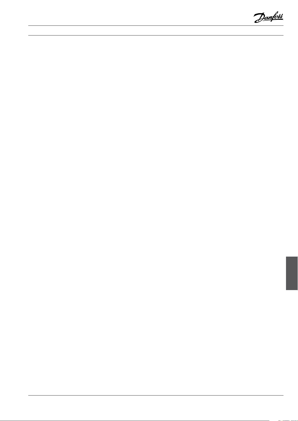
lter drier containing a solid core consisting of:
Molecular Sieves
Silica gel (low eectiveness - not used in
Danfoss driers)
Activated aluminium oxide and a polyester
mesh A inserted in the lter outlet.
DML: 100% Molecular Sieves
DCL: 80% Molecular Sieves
20% Activated aluminium
The solid core can be compared to a sponge’s
ability to soak up water and retain it.
Molecular Sieves retain water, whereas activated
aluminium oxide retains water and acids.
The solid core B together with the polyester mat
A also acts as a dirt lter.
The solid core retains large dirt particles and the
polyester mat small ones.
The lter drier is thus able to collect all dirt
particles larger than 25 micron.
Ah0_0001
Filter drier selection
The lter drier must be selected to suit the
connections and the capacity of the refrigeration
system.
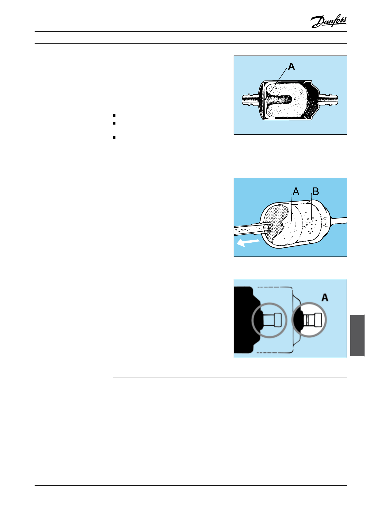
If a lter drier with solder connections is required,
a Danfoss type DCL/DML lter drier can be
used to advantage. It has an extra-high drying
capacity which prolongs the interval between
replacements.
A collar on the connector A indicates that the
connection is a mm size. If the connector A is
plain, i.e. no collar, the connector is an inch size.
Type DCL can be used for CFC/HCFC refrigerants.
Type DML can be used for HFC refrigerants. See
page 60 for more details.
Ah0_0011
Ah0_0018
Filter driers &
sight glasses
© Danfoss A/S (AC-DSL/MWA), 10 - 2006 DKRCC.PF.000.G1.02 / 520H1459 53

Fitters notes Filter driers & sight glasses
Location in
refrigeration system
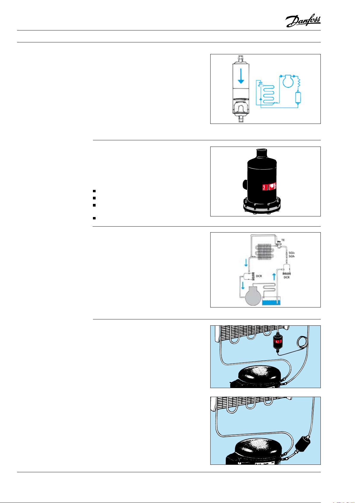
The lter drier is normally installed in the liquid
line where its primary function is to protect the
expansion valve.
The velocity of the refrigerant in the liquid
line is low and therefore contact between the
refrigerant and the solid core in the lter drier is
good. At the same time, the pressure drop across
the lter drier is low.
A lter drier can also be installed in the suction
line where its task is to protect the compressor
against dirt and dry the refrigerant.
Suction lters, so-called “burn-out” lters, are
used to remove acids after motor damage. To
ensure low pressure drop, a suction lter must
normally be larger than a liquid line lter.
A suction lter must be replaced before the
pressure drop exceeds the following values:
A/C systems: 0.50 bar
Refrigeration systems: 0.25 bar
Freezing systems: 0.15 bar
A sight glass with moisture indicator is normally
installed after the lter drier, where the sight
glass indication means:
Green: No dangerous moisture in the refrigerant.
Yellow: Moisture content too high in the
refrigerant ahead of the expansion valve.
Bubbles:
1) Pressure drop across the lter drier too high.
2) No subcooling.
3) Insucient refrigerant in whole system.
Ah0_0019
Ah0_0020
If the sight glass is installed ahead of the lter
drier the indication is:
Green: No dangerous moisture in the refrigerant.
Yellow: Moisture content in the whole
refrigeration system too high.
The changeover point from green to yellow in the
sight glass indicator is determined by the water
solubility of the refrigerant.
Note:
The changeover points in Danfoss sight glasses
are very small. This ensures that a switch to green
in the indicator only occurs when the refrigerant
is dry.
Bubbles:
1) No subcooling.
2) Insucient refrigerant in whole system.
Note!
Do not replenish refrigerant solely because of
bubbles in the sight glass.
First nd out the cause of the bubbles!
Ah0_0032
Ah0_0031
Ah0_0006
54 DKRCC.PF.000.G1.02 / 520H1459 © Danfoss A/S (AC-DSL/MWA), 10 - 2006
Fitters notes Filter driers & sight glasses
Installation
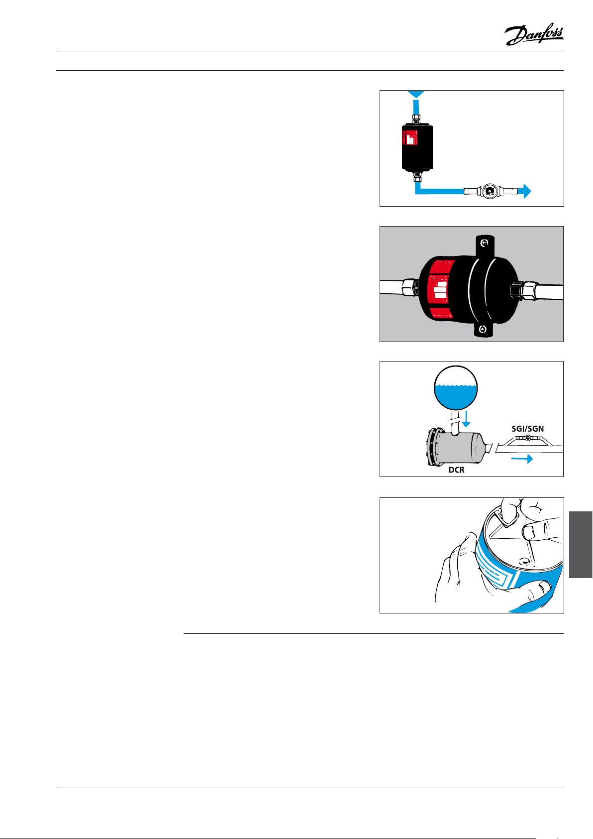
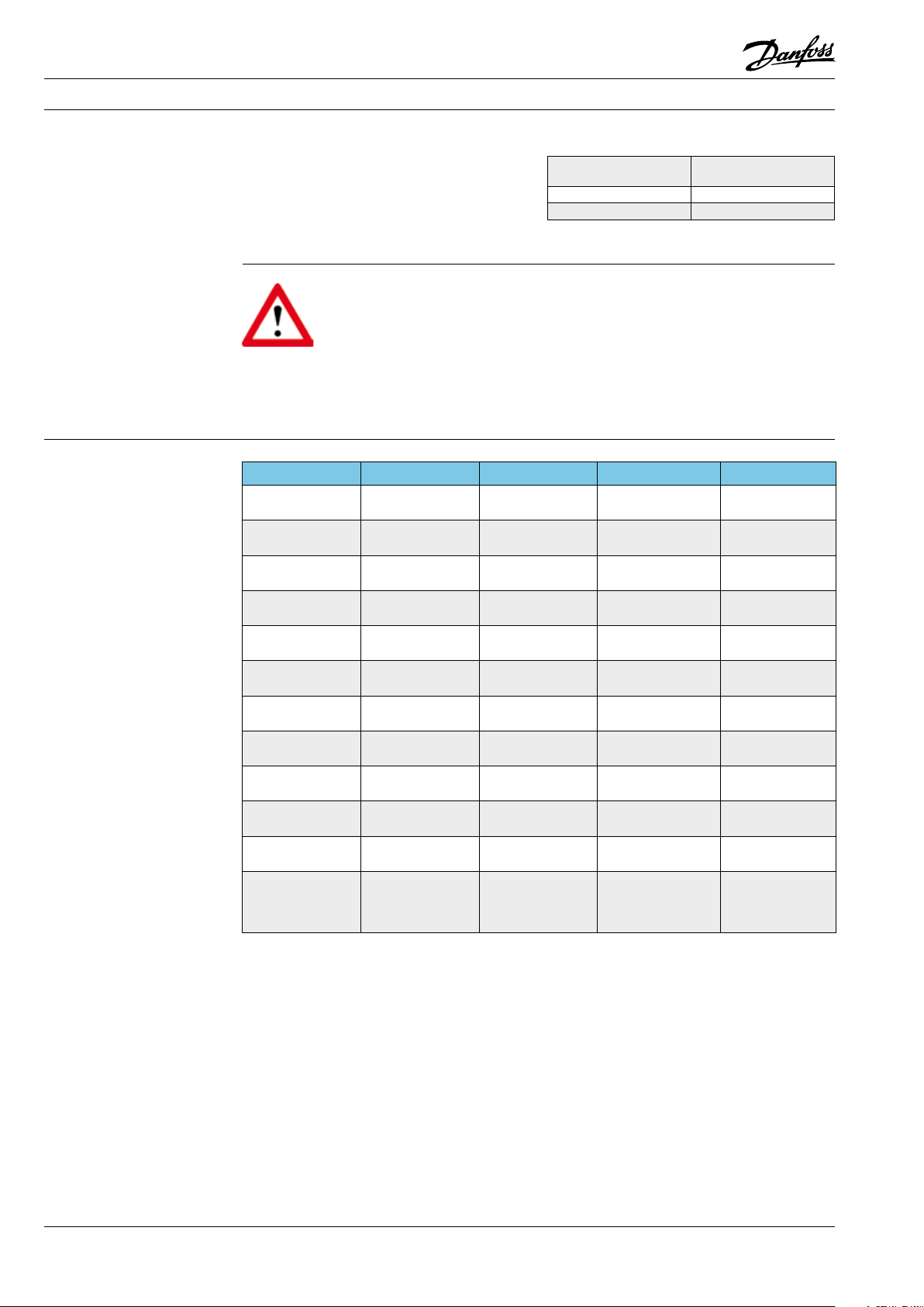
The lter drier must be installed with ow in the
direction of the arrow on the lter drier label.
The lter drier can have any orientation, but the
following must be remembered:
Vertical mounting with downward ow means
rapid evacuation/emptying of the refrigeration
system.
With vertical mounting and upward ow,
evacuation/emptying takes longer because
refrigerant must be evaporated out of the lter
drier.
The lter core is rmly xed in the lter housing.
Danfoss lter driers are therefore able to resist
vibration up to 10 g*).
Find out whether the tubing will support the
lter drier and resist vibration. If not, the lter
drier must be installed using a clamping band or
similar secured to a rigid part of the system.
*) 10 g = Ten times the gravitational force of the earth.
For DCR: Install with the inlet connector upwards
or horizontal.
This avoids collected dirt running out into the
tubing when the core is replaced.
When installing a new DCR, remember that
there must always be sucient space for core
replacement.
Ah0_0022
Ah0_0028
Do not unpack lter driers or cores until immediately before installation. This will safe-guard the
items in the best possible way.
There is neither vacuum nor overpressure in
lters or cans.
Plastic union nuts, capsolutes and the hermetically sealed can guarantee completely “fresh”
desiccants.
Ah0_0002
Ah0_0003
Filter driers &
sight glasses
© Danfoss A/S (AC-DSL/MWA), 10 - 2006 DKRCC.PF.000.G1.02 / 520H1459 55

Fitters notes Filter driers & sight glasses
Soldering
Operation
Protective gas, e.g. N2, should be used when
soldering the lter drier.
Ensure that the protective gas ows in the
direction of lter ow. This avoids heat from
soldering being damaging the polyester mesh.
Soldering alloys and ux give o
fumes that can be hazardous.
Read supplier instructions and
observe their safety stipulations.
Keep your head away from the
fumes during soldering.
Moisture enters the system:
1) When the refrigeration system is being built
up.
2) When the refrigeration system is opened for
servicing.
3) If leakage occurs on the suction side, if it is
under vacuum.
4) When the system is lled with oil or
refrigerant containing moisture.
5) If leakage occurs in a water-cooled condenser.
Moisture in the refrigeration system can cause:
a) Blockage of the expansion device because of
ice formation.
b) Corrosion of metal parts.
c) Chemical damage to the insulation in
hermetic and semihermetic compressors.
d) Oil breakdown (acid formation).
The lter drier removes moisture that remains
after evacuation or that subsequently enters the
refrigeration system.
Ah0_0004
Use strong ventilation and/or extraction at the
ame so that you do not inhale fumes and gases.
Use protective goggles.
Use wet cloth around lter driers with pure
copper connectors.
Ah0_0005
Warning!
Never use “antifreeze liquids” like
methyl alcohol together with a lter
drier. Such liquid can damage the
lter so that it is unable to absorb
water and acid.
Replace the lter drier when
1. The sight glass indicates that the moisture
content is too high (yellow).
2. Pressure drop across the lter is too high
(bubbles in sight glass during normal
operation).
3. A main component in the refrigerant system
has been replaced, e.g. the compressor.
4. Each time the refrigeration system is
otherwise opened, e.g. if the orice assembly
in an expansion valve is replaced.
Never re-use a used lter drier. It will give o
moisture if it is used in a refrigeration system with
low moisture content, or if it becomes heated.
Ah0_0008
56 DKRCC.PF.000.G1.02 / 520H1459 © Danfoss A/S (AC-DSL/MWA), 10 - 2006
Fitters notes Filter driers & sight glasses
DCR
Using gaskets
Mounting gaskets
Note, there can be overpressure in the lter.
Therefore be careful when opening the lter.
Never re-use the ange gasket in the DCR lter.
Fit a new gasket and smear it with a little refri-
geration machine oil before tightening.
Only use undamaged gaskets.
Flange surfaces that are to form the seal must
be faultless, clean and dry before mounting.
Do not use adhesive ller, rust remover
or similar chemicals when mounting or
dismantling.
1. Moisten gasket surfaces with a drop of
refrigerant oil.
2. Put gasket in place.
3. Mount bolts and tighten slightly until all bolts
have made good contact.
4. Cross-tighten bolts.
Ah0_0009
Use sucient oil for lubricating bolts and
screws during mounting.
Do not use bolts which are dry, corroded or
defective in any other way (defective bolts can
give incorrect tightening which may result in
leaking ange joints).
Tighten bolts in at least 3-4 steps, e.g. as follows:
Step 1: to approx. 10% of required torque.
Step 2: to approx. 30% of required torque.
Step 3: to approx. 60% of required torque.
Step 4: to 100% of required torque.
Finally, check that the torque is correct in the
same order as used when tightening.
Disposal
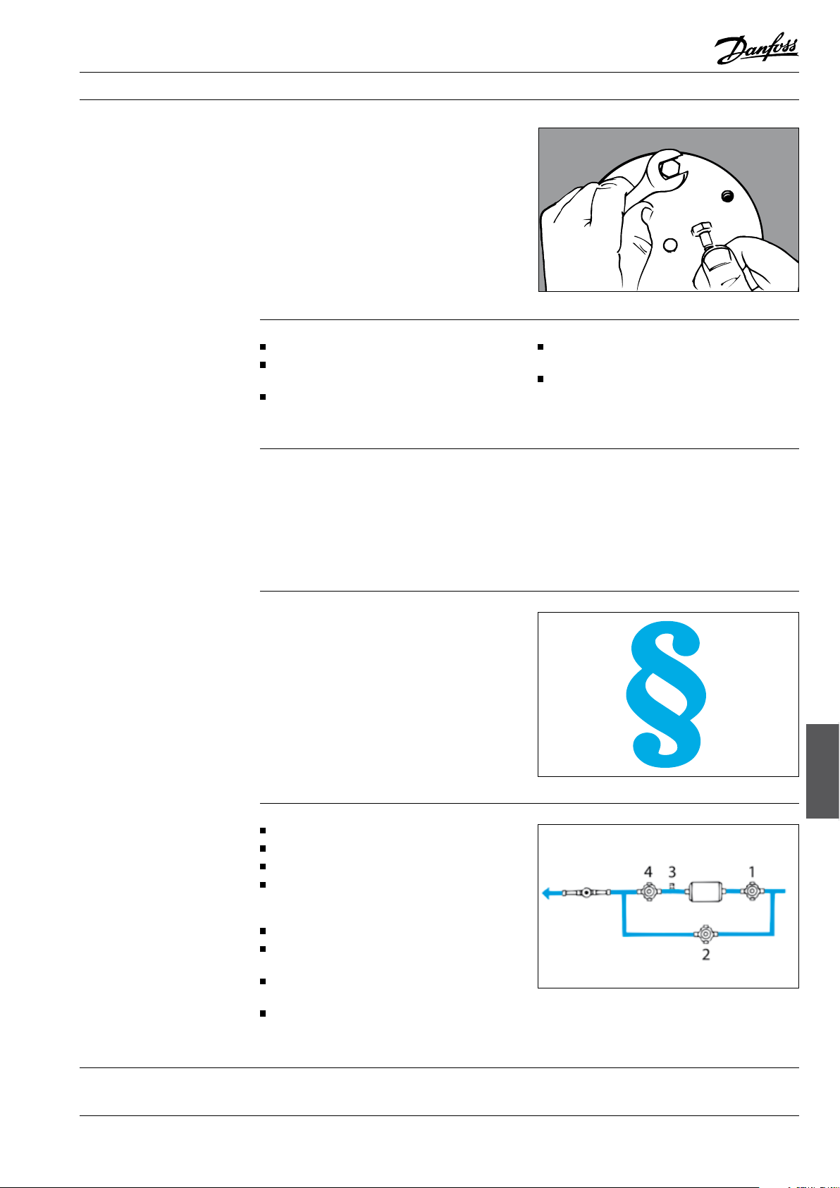
Filter drier replacement
Always seal used lter driers. They contain small
amounts of refrigerant and oil residue.
Observe authority requirements when scrapping
used lter driers.
Close valve no. 1.
Suck the lter empty.
Close valve no. 4.
Close valve no. 2.
The system will now operate, bypassing the lter.
Replace lter or lter core.
Evacuate the lter drier via a schrader valve
(no. 3).
Restart the system by opening/closing the
valves in the reverse order.
Remove any levers/handwheels from the
valves.
Ah0_0023
Ah0_0014
Filter driers &
sight glasses
© Danfoss A/S (AC-DSL/MWA), 10 - 2006 DKRCC.PF.000.G1.02 / 520H1459 57
Fitters notes Filter driers & sight glasses
Special lters from Danfoss
Combidriers type DCC and DMC
Burn-out lter, type 48-DA
Combidriers type DCC and DMC are used in
smaller systems with expansion valve where the
condenser cannot contain the entire quantity of
refrigerant.
The receiver in the combidrier increases liquid
subcooling and creates the possibility of
automatic defrost on pumpdown. The receiver
takes up varying refrigerant volume (from varying
condensing temperature) and must be able to
contain the whole refrigerant quantity during
service and repair.
In the interests of safety, the volume of the
receiver must be at least 15% greater than the
refrigerant volume.
Burn-out lter, type 48-DA, is for use after a
hermetic or semihermetic compressor has
suered damage.
Compressor damage that gives rise to acid
formation will be revealed by oil odour and
perhaps discolouration. Damage can occur
because of:
moisture, dirt or air
defective starter
refrigerant failure because of too small a
refrigerant charge,
hot gas temperature higher than 175°C
Ah0_0012
Ah0_0013
After replacing the compressor and cleaning
the remainder of the system, two burn-out
lters are installed; one in the liquid line and
one in the suction line.
The acid content is then checked regularly
and the lters replaced as necessary.
When an oil check shows that the system no
longer contains acid, the burn-out lter in
the liquid line can be replaced by an ordinary
lter drier. The burn-out lter core in the
suction line can be removed.
Ah0_0010
Special application
DCL/DML lter driers
Type DCL/DML 032s, DCL/DML 032.5s and
DCL/DML 033s are manufactured specially for
capillary tube systems and are therefore used in
refrigeration systems where expansion is through
a capillary tube.
Ah0_0017
DCL/DML lter driers can also be used when
reparing refrigerators and freezers, etc. Both time
and money can be saved by installing a DCL/DML
lter drier in the suction line.
The advantage of doing so can best be illustrated
by comparing the normal repair procedure for a
defective compressor with a method that exploits
the good characteristics of the DCL/DML lter in
retaining moisture, acid and dirt.
NOTE: The „DCL/DML method“ can only be used
when the oil is not discoloured and when
the pencil lter is not clogged.
Ah0_0015
58 DKRCC.PF.000.G1.02 / 520H1459 © Danfoss A/S (AC-DSL/MWA), 10 - 2006

Fitters notes Filter driers & sight glasses
Special application
DCL/DML lter driers (cont.)
Dimensioning
The advantages gained by installing a DCL/DML
lter in the suction line are:
1. Faster repair.
2. Increased drying and acid capacity.
3. Protection of the compressor against
impurities of every kind.
4. Better quality of repair.
5. Cleaner working environment.
The acid and moisture bound in the old oil will be
absorbed by the DCL/DML lter.
Therefore it is not necessary to remove remaining
oil from the refrigeration system.
A DCL/DML in the suction line retains impurities
from condenser, evaporator, tubing, etc. and
thereby prolongs the life of the new compressor.
DCL/DML lters having the same connections
as the compressor can be used. The Danfoss
range of hermetic compressors can also be
recommended.
When choosing lter driers from catalogues there
are several expressions each of which can form
the basis of selection.
Procedure with pencil lter Procedure with
Recover refrigerant and
evaluate for re-use
Remove compressor
+ pencil lter
Remove oil residue in system Nothing
Dry system with nitrogen Nothing
Connect new compressor and
t new pencil lter
Evaluate and change
refrigerant
DCL/DML lter
Recover refrigerant and
evaluate for re-use
Remove compressor
Connect new compressor
and t DCL/DML lter in
suction line
Evaluate and change
refrigerant
Example:
Compressor type Suction tube
TL Ø6.2 DCL/DML 032s
NL 6-7 Ø6.2 DCL/DML 032s
[mm]
Filter type
EPD (Equilibrium Point Dryness)
Drying capacity (water capacity)
Liquid capacity (ARI 710*)
Denes the least possible water content in a
refrigerant in its liquid phase, after it has been in
contact with a lter drier.
EPD for R22 = 60 ppmW *)
EPD for R410A = 50 ppmW *)
EPD for R134a = 50 ppmW *)
EPD for R404A / R507 / R407C = 50 ppmW *)
As stipulated by ARI 710, in ppmW
(mg
/kg
water
*) ARI: Air-conditioning and Refrigeration Institute, Virginia, USA
refrigerant
)
The quantity of water the lter drier is able to
absorb at 24°C and 52°C liquid temperature, as
stipulated by the ARI 710* standard.
The drying capacity is given in grams of water,
drops of water or kg refrigerant on drying out.
R22: 1050 ppmW to 60 ppmW
R410A: 1050 ppmW to 50 ppmW
R134a: 1050 ppmW to 50 ppmW
R404A / R507 / R407C: 1020 ppmW to 50 ppmW
1000 ppmW = 1 g water in 1 kg refrigerant 1 g water = 20 drops.
Gives the quantity of liquid able to ow through
a lter with a pressure drop of 0.07 bar at tc =
+30°C, te = -15°C.
The liquid capacity is stated in l/min or in kW.
Conversion from kW to litres/minute:
R22 / R410A 1kW = 0.32 l/min
R134a 1kW = 0.35 l/min
R404A / R507 / R407C 1kW = 0.52 l/min
*) ARI: Air-conditioning and Refrigeration Institute, Virginia, USA
Ah0_0025
Ah0_0016
Ah0_0024
Filter driers &
sight glasses
© Danfoss A/S (AC-DSL/MWA), 10 - 2006 DKRCC.PF.000.G1.02 / 520H1459 59
Fitters notes Filter driers & sight glasses
Recommended system capacity
Filter driers from Danfoss
Operating conditions:Stated in kW for dierent types of refrigeration
systems on the basis of a liquid capacity of
∆p = 0.14 bar and typical operating conditions.
Refrigeration
and freezing systems
A/C systems
A/C units
te = evaporating temperature
tc = condensing temperature
te = -15°C, tc = +30°C
te = -5°C, tc = +45°C
te = +5°C, tc = +45°C
Warning:
With the same system capacity in
kW for A/C units and for
refrigeration/freezing systems,
smaller lter driers can be installed
in A/C units because of higher evaporating
temperature (te) and the assumption that factory
produced units contain less moisture than
systems built up „on site“.
Product type Function Refrigerant Core Oil type
DML Standard lter drier HFC, compatible with
DCL Standard lter drier CFC/HCFC 80% molecular sieves
DMB Bi-ow lter drier HFC, compatible with
DCB Bi-ow lter drier CFC/HCFC 80% molecular sieves
DMC Combi lter drier HFC, compatible with
DCC Combi lter drier CFC/HCFC 80% molecular sieves
DAS Burn-out lter drier R22, R134a,
DCR Filter drier with ex-
48-DU/DM
for DCR
48-DN/DC
for DCR
48-DA
for DCR
48-F
for DCR
changeable core
Exchangeable core for
DCR: std. lter drier
Exchangeable core for
DCR: std. lter drier
Exchangeable core for
DCR: std. lter drier
Exchangeable
core for DCR with
exchangeable lter
insert
R22
R22
R22
R404A, R507
See core description
below
HFC, compatible with
R22
CFC/HCFC 80% molecular sieves
R22, R134a,
R404A, R507
All - All
100% molecular sieves Polyolester (POE)
20% activated alumina
100% molecular sieves Polyolester (POE)
20% activated alumina
100% molecular sieves Polyolester (POE)
20% activated alumina
30% molecular sieves
70% activated alumina
48-DU/DM, 48-DN DC,
48-DA, 48-F
100% molecular sieves Polyolester (POE)
20% activated alumina
Polyalkyl (PAG)
Mineral oil (MO)
Alkyl benzene (BE)
Polyalkyl (PAG)
Mineral oil (MO)
Alkyl benzene (BE)
Polyalkyl (PAG)
Mineral oil (MO)
Alkyl benzene (BE)
-
Polyalkyl (PAG)
Mineral oil (MO)
Alkyl benzene (BE)
60 DKRCC.PF.000.G1.02 / 520H1459 © Danfoss A/S (AC-DSL/MWA), 10 - 2006
 Loading...