

Page 1
Data Sheet
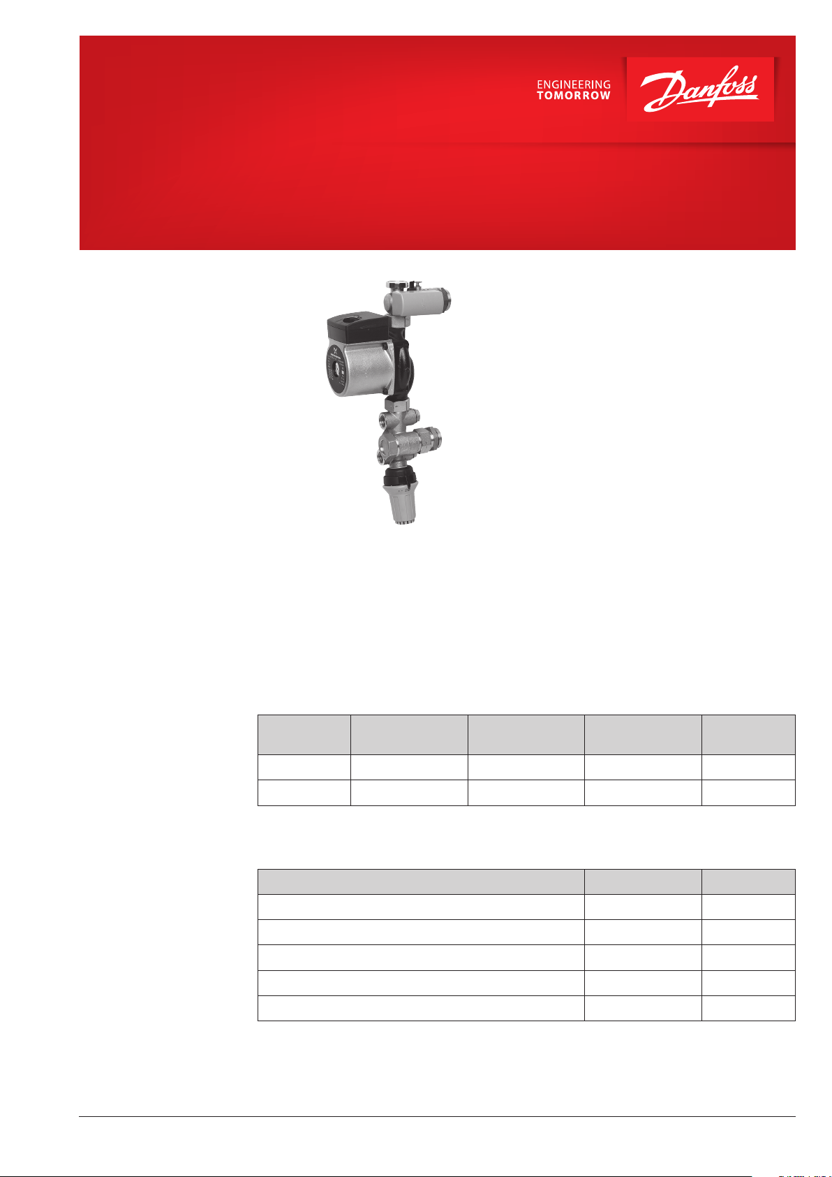
FHM-C5, FHM-C6
Mixing Shunts for Floor Heating
Application
Mixing shunt FHM-C5 and FHM-C6
The Danfoss compact mixing shunts are used
for regulation of flow and supply temperature in
hydronic floor heating systems.
The compact, flexible design allows mounting the
mixing shunt directly to the manifold on both left
and right side, with the primary pipe connection
from the side or below.
A self-acting proportional regulator is used to
regulate the supply temperature. The regulator
ensures that the desired supply temperature to
the underfloor heating system always remains
constant.
A built-in check valve ensures correct flow direction.
An air-vent on top and a thermometer completes
the mixing shunt. An optional thermostat protects
the floor against too high temperatures.
FHM-C5 and FHM-C6 have a standard 3-speed
pump (UPS).
FHM-C5 and FHM-C6 compact mixing shunts can
be mounted directly to the Danfoss manifold
system without the use of special equipment.
By using Danfoss floor heating controls all
expectations of a professional floor heating
system are fullfilled.
Should water treatment be used it is essential that
dosing instructions of the manufacturer are strictly
observed. It is recommended that formulations
containing mineral oil are avoided.
Ordering
Accessories
Product
FHM-C5 4,5 kW 9 kW UPS 15-40 088U0093
FHM-C6 7 kW 13 kW UPS 15-60 088U0096
1)
Max. effect at Δt = 30K in primary (70/40) and Δt = 5K (10K) in secondary line with heatloss 50 W/m².
Product Type Code no.
Thermometer 0 °C to 60 °C, Ø 35 mm FHD-T 088U0029
Safety thermostat FH-ST55 088U0301
Temperature controller, 15 °C to 50 °C FTC 013G5081
Measuring set for needles FHM-MS 088U0304
Angle fittings (set of 2 pcs.) FHM-AF 088U0305
Max. effect at
sec. Δt = 5K
Max. effect at
sec. Δt = 10K
1)
Pump type,
Grundfos
Code no.
© Danfoss | FEC | 2020.06
AI304357196452en-000101 | 1
Page 2
Data Sheet FHM-C5, FHM-C6 Mixing Shunts for Floor Heating
Technical specifications
FH-ST55
Safety thermostat
Supply voltage 230 V AC
Primary connection ½”
Max. differential pressure with Danfoss Floor
Heating manifolds
0,6 bar
Max. working pressure PN10
Max. flow temperature 90 °C
FTC flow temperature control 18 °C to 50 °C
FH-DT supply flow thermometer 0 °C to 60 °C
Integrated check valve POM / Stainless steel
Body, unions and other metal parts Brass / Stainless steel
O-rings and seals EPDM
Weight approx. 3,5 kg to 4 kg (depending on model)
230V / 16A
T
55°C
S
Electrical connection
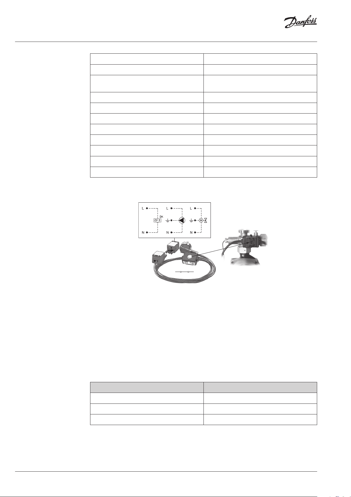
The FH-ST safety thermostat is fixed on the tube
and protects floor and system against too high
temperatures, especially important for wooden
floors. The FH-ST thermostat switches off the pow-
By switching off the power supply of the floor
heating base unit, the actuators (NC) will close
automatically and the floor heating system is pro-
tected.
er supply of the floor heating base unit, when the
temperature reaches 55 °C.
The FH-ST55 can also be connected to a pump or
a zone valve.
Note! The electrical installation must be carried out
by an authorized installer only (230 V DC).
Code no. 088U0301
Shut-off temperature 55 °C
Switch difference 4 K
Classification IP 40 (mounted)
2 | © Danfoss | FEC | 2020.06
AI304357196452en-000101
Page 3

Data Sheet FHM-C5, FHM-C6 Mixing Shunts for Floor Heating
FTC
Temperature controller
FHM-MS
Measuring set
FTC is a self-acting thermostatic sensor used for
flow temperature control of floor heating.
The water temperature is measured by a surface
sensor. The snap-lock connector of the sensor
element secures a firm connection to the valve.
Features:
• Closes on rising sensor temperature.
• Temperature range: 15 to 50 °C
PFM 100/5001
FHM-MS measuring set
The flow running through the FHM-MS (fixed
orifice) can be measured by using the Danfoss
measuring instruments PFM 100/5001 or other
brands of measuring equipment.
The FHM-MS valve is supplied with two measuring
nipples for 3 mm needles. The measuring nipples
kvs 7.4
are placed across a fixed orifice and the differential
pressure can be measured across this orifice.
The value of the fixed orifice (kvs 7.4) and the
differential pressure will be used in the measuring
equipment to define the flow. Measuring on a
fixed orifice valve is very fast and easy.
© Danfoss | FEC | 2020.06
AI304357196452en-000101 | 3
Page 4

Data Sheet FHM-C5, FHM-C6 Mixing Shunts for Floor Heating
L/
0 6 17
FHM-FL
Flow limiter
h
FHM-FL flow limiter
System
FHM-C
Combined floor heating system with boiler
FHM-C
Combined floor heating system with heat pump
4 | © Danfoss | FEC | 2020.06
AI304357196452en-000101
Page 5

Danfos
produc
Al
Danfoss A/S
Heating Segment • heating
Dimensions
112
190
382
25
213
382
62
23
9
FHM- C5 & FHM-C6
59
s can accept no responsibility for possible errors in catalogues, brochures and o ther printed material. Danfoss reserves the right to alter its products w ithout notice. This also applies to
ts already on order provided that such alterations can be m ade without subsequential changes being necessary in specications already agreed.
l trademarks in this material are p roperty of the respective companies. Danfoss and all Danfoss logot ypes are trademarks of Danfoss A/S. All rights reserved.
© Danfoss | FEC | 2020.06
.danfoss.com • +45 7488 2222 • E-Mail: [email protected]
AI304357196452en-000101 | 5
 Loading...