

Installation guide
Strainer in stainless steel
FIA SS 15-65
Installation / Instalación / Installazione / 安装 / Montaż / Монтаж
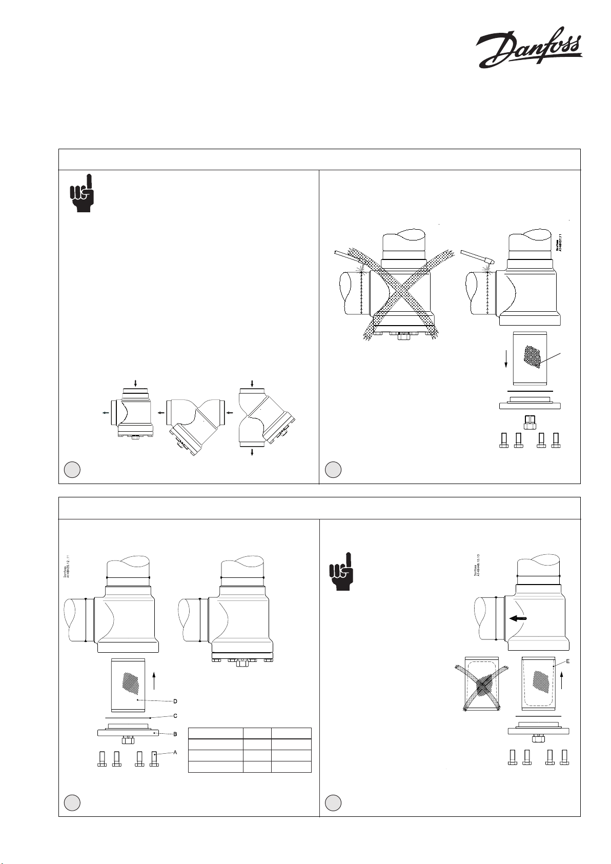
Note:
148R9614
At delivery the strainer housing is not equipped with lter
element or accessories.
Hinweis:
Das Filtergehäuse ist bei Lieferung nicht mit
Filtersieb oder Zubehör ausgestattet.
Remarque:
Le corps du ltre est livré sans élément et sans accessoire.
Nota:
En el momento de su entrega, la carcasa del ltro no incorpora la
malla de ltro ni ningún tipo de accesorio.
Nota:
Alla consegna, l’involucro del ltro non è dotato dell’elemento
ltrante o di accessori
注意:
在交付时,过滤器外壳没有配备过滤器元件或配件
Uwaga:
W dostarczanym korpusie ltra nie ma wkładu
ani akcesoriów
Примечание:
При поставке корпус фильтра не оснащен ни фильтрующим
элементом, ни вспомогательными приспособлениями
148R9614
D
Danfoss
148H115_06-2014
1 2
FIA SS 15-65
Maintenance / Wartung / Mantenimiento / Manutenzione / 维护 / Serwis / Техническое обслуживание
Striner bag
Flow direction
Filtersack
Durchussrichtung
Sac ltrant
Direction du ux
Bolsa ltrante
Sentido del ujo
Sacchetto ltro
Portata
过滤包
流向
Max. torque / M ax. Drehmoment /
Couple max . / Par de apriete máximo /
Coppia max . / 最大扭矩 / Maks. moment
dokręcenia / Макс. момент затяжки
Nm LB-ft
DN 15-20 21 15
DN 25-32-40-50 44 32
DN 65 74 54
Filtr workowy
Kierunek przepływu
Установка фильтруещего мешка
Направление потока
3
4
© Danfoss | DCS (MWA) | 2015.05 DKRCI.PI.FN1.C3.ML / 520H8211 1

ENGLISH
Refrigerants
Applicable to HCFC, HFC, R717 (Ammonia),
R744 (CO2) and all ammable refrigerants.
The strainer is only recommended for use
in closed circuits. For further information
please contact your local Danfoss sales
oce.
Pressure and temperature range
–60/+150°C (–76/+302°F)
FIA SS 15-65:
The strainers are designed for a max.
working pressure of 52 bar (754 psi g)
Installation
Note:
At delivery the strainer housing
is not equipped with strainer
element or accessories
The strainer must be installed with the top
cover downwards, and the ow must be
directed towards the top cover as indicated
by the arrow on the strainer housing (g.
1). The strainer element must be inserted
after welding.
The strainer housing is designed to
withstand a high internal pressure.
However, the piping system should be
designed to avoid liquid traps and reduce
the risk of hydraulic pressure caused by
thermal expansion. It must be ensured
that the strainer is protected from pressure
transients like “liquid hammer” in the
system.
Recommended ow direction
The strainer must be installed with the ow
towards the top cover as indicated by the
arrow on the side of the valve body (g.
1). Flow in the opposite direction is not
acceptable.
Welding
To prevent damage to the gasket between
the strainer body and top cover, the top
cover should be removed before welding
and protect it from dirt and moisture (g.
2).
Only materials and welding methods,
compatible with the valve housing
material, must be welded to the valve
housing.
Clean the strainer housing internally to
remove welding debris at completion
of welding and before the valve is
reassembled.
Removing the top cover can be omitted
provided that:
The temperature in the area between the
valve body and top cover during welding
does not exceed +150°C/+302°F.
This temperature depends on the welding
method as well as on any cooling of the
strainer body during the welding itself.
(Cooling can be ensured by, for example,
wrapping a wet cloth around the strainer
body.) Make sure that no dirt, welding
debris etc. get into the strainer during the
welding procedure.
The strainer housing must be free from
stresses (external loads) after installation.
Strainers must not be mounted in systems
where the outlet side of the strainer is
open to atmosphere. The outlet side of the
strainer must always be connected to the
system or properly capped o, for example
with a welded-on end plate.
Assembly
Remove welding debris and any dirt from
pipes and strainer body before assembly.
Check that the strainer element has
the right size before it is inserted in the
top cover and check that the gasket is
undamaged.
Place the strainer element (pos. D) from
underneath. The element has a slight force
t into the housing, no gaskets or O-rings
are used.
If magnet inserts have been chosen as
accessory, t those on the top cover before
replacing the cover.
Tightening
Tighten the top cover with a torque
wrench, to the values indicated in the table
(g. 3).
Please note that the table (g. 3)
containing maximum torque must be
adhered to and never exceeded.
If the drain valve has been chosen as
accessory, the drain plug should be
replaced by the drain valve.
Colours and identication
The FIA SS valves are painted with a
red oxide primer in the factory. Precise
identication of the valve is made via the
ID plate on the top cover, as well as by the
stamping on the valve body. The external
surface of the valve housing must be
prevented against corrosion with a suitable
protective coating after installation and
assembly.
Be sure to protect the ID plate when
repainting the valve.
Maintenance
Mounting of accessory:
Strainer bag (g. 4)
A 50µ strainer bag (pos. E), especially for
commissioning of the plant, can replace
the normal strainer element.
Mount the strainer bag (held in place by
the strainer holder) and be sure to place
the strainer bag correctly in the strainer as
shown in g. 4.
The ow must go into the strainer bag
cavity and out or else the bag will not
function properly.
Dismantling the strainer (g. 3)
Before servicing the strainer, isolate it from
the system and remove all refrigerant by
evacuation to zero pressure. Check for
refrigerant pressure before unscrewing and
removal of the top cover.
The strainer element must be removed
without any use of tools
Cleaning
Clean the strainer element using an
appropriate solvent by ushing and
brushing. The use of strong acids cannot be
recommended. The strainer element must
be wiped or blown dry before inspection. If
the element is damaged or the sediments
cannot be removed, the strainer element
must be replaced.
Assembly
Remove any dirt from the body before the
strainer is assembled.
Replacement of gasket
Change the gasket for the top cover (pos.
C) and drain plug.
Check that the strainer element is correctly
placed before remounting the top cover
and bolts (pos. A).
Tightening (g. 3)
Tighten the top cover bolts (pos. A) with
a torque wrench according to the table in
g. 3
Use only original Danfoss parts (including
gaskets) for replacement. Materials of
new parts are certied for the relevant
refrigerant.
In cases of doubt, please contact your local
Danfoss sales oce.
2 DKRCI.PI.FN1.C3.ML / 520H8211 © Danfoss | DCS (MWA) | 2015.05
DEUTSCH
Kältemittel
Anwendbar für HFCKW, HFKW, R717
(Ammoniak), R744 (CO2) und alle
brennbaren Kältemitteln.
Der Filter ist nur für die Verwendung in
geschlossenen Kreisläufen empfohlen. Für
weitere Informationen wenden Sie sich bitte
an Danfoss.
Temperatur- und Druckbereich
–60/+150°C
FIA SS 15-65:
Die Filter sind für einen max. Betriebsdruck
von 52 bar (754 psi g) ausgelegt.
Installation
Hinweis:
Das Filtergehäuse ist bei lieferung
nicht mit Filtersieb oder Zubehör
ausgestattet.
Der Filter muss mit dem Kopfdeckel
nach unten eingebaut werden und der
Durchuss muss in Pfeilrichtung auf dem
Filtergehäuse zum Kopfdeckel geleitet
werden (Abb. 1). Das Filtersieb darf erst
nach Schweißarbeiten eingesetzt werden.
Der Filter ist für einen hohen Innendruck
ausgelegt. Das Verrohrungssystem
sollte jedoch so ausgelegt sein, um
Flüssigkeitseinschlüsse zu verhindern
und das Risiko von Hydraulikdruck
verursacht durch Wärmeausdehnung zu
minimieren. Es muss sichergestellt werden,
dass der Filter vor Druckstößen wie
Flüssigkeitschläge im System geschützt ist.
Empfohlene Durchussrichtung
Der Filter muss mit dem Durchuss in
Pfeilrichtung auf dem Filtergehäuse zum
Kopfdeckel eingebaut werden (Abb.
1). Durchuss in der entgegengesetzten
Richtung ist nicht zulässig.
Schweißen
Der Kopfdeckel muss vor dem
Schweißen entfernt und vor Schmutz
und Feuchtigkeit geschützt werden
(Abb. 2), um Beschädigung an der
Dichtung zwischen Filtergehäuse und
Kopfdeckel zu verhindern. Nur mit
dem Filtergehäusewerksto verträglich
Werkstoe und Schweißverfahren dürfen
beim Schweißen des Filtergehäuses
verwendet werden.
Der Filter sollte nach dem Schweißen
und vor dem Zusammenbau innen
gereinigt werden, um Schweißüberreste zu
entfernen.
Das Entfernen des Kopfdeckels kann
entfallen, wenn:
Die Temperatur im Bereich zwischen
Ventilgehäuse und Kopfdeckel
während des Schweißens +150 °C nicht
überschreitet.
Diese Temperatur hängt sowohl vom
Schweißverfahren als auch von der
Kühlung des Filtergehäuses während des
eigentlichen Schweißens ab. (Kühlung
kann zum Beispiel sichergestellt werden,
indem ein nasses Tuch während des
Schweißvorgangs um das Filtergehäuse
gewickelt wird).
Es ist sicherzustellen, dass kein Schmutz,
keine Schweißüberreste usw. während
des Schweißens in den Filter gelangen.
Das Filtergehäuse muss nach dem Einbau
frei von Beanspruchungen (externen
Belastungen) sein. Filter dürfen nicht in
Systemen eingebaut werden, in denen die
Auslassseite des Filters zur Atmosphäre
oen ist.
Die Auslassseite des Filters muss immer
an das System angeschlossen oder fest
verschlossen werden, zum Beispiel mit
einem angeschweißten Endblech.
Zusammenbau
Vor dem Zusammenbau Schweißüberreste
und Schmutz von Rohrleitungen und
Filtergehäuse entfernen. Bevor das
Filtersieb in den Kopfdeckel eingesetzt
wird, ist sicher zu stellen, dass es die
richtige Größe hat. Auch sicherstellen, dass
die Dichtung nicht beschädigt ist.
Das Filtersieb (Pos. D) von unten einsetzen.
Das Filtersieb hat leichte Presspassung
im Gehäuse, es werden keine Dichtungen
oder O-Ringe verwendet. Wenn Magnete
als Zubehör gewählt wurden, sollten
diese vor der Montage des Deckels am
Kopfdeckel befestigt werden.
Anziehen
Den Kopfdeckel mit einem
Drehmomentschlüssel anziehen (Werte
bitte in der Tabelle Abb. 3 entnehmen.
Bitte beachten, dass es sich hierbei um
maximalwerte handelt, die niemals
überschritten werde dürfen).
Wenn das Ablassventil als Zubehör gewählt
wurde, sollte der Ablassstopfen durch das
Ablassventil ersetzt werden.
Farben und Kennzeichnungen
Die FIA SS-Ventile werden ab Werk
mit Rotoxid grundiert. Eindeutige
Kennzeichnung des Ventils erfolgt über
den Kennring am Kopfdeckel sowie
die Prägung am Ventilgehäuse. Die
Außenäche des Ventilgehäuses muss
nach dem Einbau und dem Zusammenbau
mit einer geeigneten Schutzbeschichtung
gegen Korrosion geschützt werden.
Beim Neulackieren des Ventils wird Schutz
des Kennschilds empfohlen.
Wartung
Einbau des Zubehörs:
Filtersack (Abb. 4)
Ein 50-μ-Filtersack (Pos. E) kann das
normale Filtersieb speziell für die
Inbetriebnahme der Anlage ersetzen.
Beim Einbau des Filtersacks, der über einen
Filterhalter befestigt wird, muss äußerste
Vorsicht walten gelassen werden, um den
Filtersack wie in Abb. 4 gezeigt in den
Filter richtig einzusetzen. Der Durchuss
muss in den Filtersackhohlraum gehen, da
andernfalls der Filtersack nicht einwandfrei
funktioniert. Die Funktionsfähigkeit des
Filters ist nur gegeben, wenn auf die
richtige Durchussrichtung des Filterventils
geachtet wurde.
Zerlegen des Filters (Abb. 3)
Vor der Wartung von Filterventilen
sind diese vom System zu trennen und
sämtliches Kältemittel aus der Anlage
zu evakuieren. Vor dem Abschrauben
und Entfernen des Kopfdeckels ist der
Kältemitteldruck zu überprüfen. Das
Filtersieb muss ohne Werkzeug ausgebaut
werden.
Reinigung
Das Filtersieb kann mit einem
entsprechenden Lösungsmittel durch
Spülen und Bürsten gereinigt werden.
Von der Verwendung starker Säuren
wird abgeraten. Das Filtersieb sollte
vor der Überprüfung abgewischt
oder trocken geblasen werden. Ist das
Filtersieb beschädigt oder können die
Schmutzrückstände nicht entfernt werden,
muss das Filtersieb ersetzt werden.
Zusammenbau
Vor dem Zusammenbau des Filters
jeglichen Schmutz vom Gehäuse
entfernen.
Austausch der Dichtung
Es wird empfohlen, die Dichtung für den
Kopfdeckel (Pos. C) und Ablassstopfen
immer auszutauschen. Sicherstellen, dass
das Filtersieb richtig eingesetzt ist, bevor
der Kopfdeckel und die Schrauben (Pos. A)
wieder angebracht werden.
Anziehen (Abb. 3)
Die Kopfdeckelschrauben (Pos. A) mit
einem Drehmomentschlüssel auf die Werte
in der Tabelle in Abb. 3 anziehen.
Nur Originalteile von Danfoss einschließlich
Dichtungen zum Austausch verwenden.
Werkstoe neuer Teile sind für das
betreende Kältemittel zertiziert.
Wenden Sie sich im Zweifelsfall bitte an
Danfoss.
© Danfoss | DCS (MWA) | 2015.05 DKRCI.PI.FN1.C3.ML / 520H8211 3

FRANÇAIS
Fluides frigorigènes
Applicable aux uides frigorigènes HCFC,
HFC, R717 (ammoniac), R744 (CO2) et à tous
les uides frigorigènes inammables.
Ce ltre est préconisé uniquement pour les
circuits fermés. Contactez Danfoss pour de
plus amples informations.
Plage de pressions et de températures
-60/+150°C
FIA SS15-65
Les ltres sont conçus pour une pression
de service maximale de 52bar.
Installation
Remarque:
Le corps du ltre est livré sans
élément ltrant et sans accessoire.
Le ltre doit être installé avec le couvercle
supérieur vers le bas et le débit doit être
dirigé vers le couvercle supérieur, tel
qu’indiqué par la
(g.1). Les éléments
insérés après la soudure.
Le ltre est conçu pour supporter une
pression interne élevée. Toutefois, il convient
de concevoir le circuit
pièges à liquide et réduire les risques de
formation d’une pression hydraulique sous
l’eet de la dilatation thermique.
que le ltre soit protégé des variations de
pression au sein du circuit comme les
«coups de bélier».
Sens de débit recommandé
Le ltre doit être installé avec le débit
dirigé vers le couvercle supérieur, tel
qu’indiqué par la èche située sur le côté du
corps du ltre
opposé n’est pas admis.
Soudure
Retirez le couvercle supérieur avant de
souder (g. 2), an de ne pas endommager
le joint d’étanchéité entre le corps du ltre
et le couvercle supérieur et protéger le de
la poussière et de l’humidité.
Veillez à faire usage de matériaux et de
procédures compatibles avec le matériau
du corps du ltre, pour eectuer des
soudures sur ce dernier.
Nettoyez l’intérieur du ltre
les résidus de soudure une fois
terminé, avant de procéder au remontage
du ltre.
Le couvercle supérieur peut rester en place
uniquement si :
La température dans la zone comprise
entre le corps du ltre et le couvercle
supérieur lors de la soudure n’excède pas
+150°C.
èche du corps du ltre
ltrants doivent être
de façon à éviter les
Veillez à ce
(g.1). Un débit dans le sens
pour évacuer
le soudage
Cette température dépend de la méthode
de soudure appliquée ainsi que du
refroidissement du corps du ltre pendant
la soudure.
Le refroidissement peut être assuré, par
exemple, en enroulant un chion humide
autour du corps du ltre. Veillez à ce
qu’aucune impureté ou résidu de soudure,
etc. ne s’introduise dans le ltre pendant la
soudure.
Le ltre doit être exempt de contraintes
(pressions externes) après l’installation.
Les ltres ne doivent en aucun cas être
montés dans des circuits où la sortie du
ltre serait mise à l’atmosphère. La sortie
du ltre doit systématiquement être
raccordée au circuit ou ouverte comme il
se doit, par exemple à l’aide d’un embout
soudé.
Montage
Retirez les résidus de soudure et les
impuretés des conduites et du ltre avant
de procéder au montage. Vériez que
l’élément ltrant est à la bonne taille avant
de l’insérer dans le couvercle supérieur et
vériez que le joint d’étanchéité n’est pas
endommagé.
Placez l’élément ltrant (pos. D) par le
dessous. L’élément s’ajuste au corps en
forçant légèrement: aucun joint torique
ni joint d’étanchéité n’est requis.
Si des inserts magnétiques font partie des
accessoires, ajustez-les sur le couvercle
supérieur avant de replacer le couvercle.
Serrage
Serrez le couvercle supérieur à l'aide d'une
clé dynamométrique, conformément aux
valeurs indiquées dans le tableau (g.3).
Veuillez noter que la valeur de couple
maximale contenue dans le tableau (g.3)
doit être respectée et en aucun cas être
dépassée.
Si le robinet de vidange fait partie des
accessoires, il doit remplacer le bouchon
de vidange.
Couleurs et identication
Les ltres FIA SS sont recouverts en usine
d’une couche de peinture primaire
rouge.
Le ltre peut être indentié
précisément à l’aide de la plaque
d’identication apposé sur le couvercle
supérieur, ainsi que par un estampillage sur
le corps du ltre. La surface extérieure du
ltre doit être protégé de la corrosion
l’aide d’un revêtement adéquat
l’installation et du montage.
Veillez à protéger la plaque
d’indentication lorsque le ltre est
repeint.
à
à l’issue de
Maintenance
Montage des accessoires:
Sac ltrant (g.4)
Un sac ltrant de 50µ (pos. E), en
particulier pour la mise en service de
l’installation, peut remplacer l’élément
ltrant normal.
Montez le sac ltrant (maintenu en place
par un porte-ltre) et veillez à positionner
le sac ltrant correctement sur le ltre
comme indiqué sur la g.4.
Le débit doit pouvoir traverser la cavité du
sac ltrant. Dans le cas contraire, le sac ne
fonctionne pas correctement.
Démontage du ltre (g.3)
Avant d’intervenir sur les ltres, il est
nécessaire de les isoler du système et
d’éliminer
évacuation à une pression nulle. Vériez la
pression du uide avant de dévisser et de
retirer le couvercle supérieur.
Les éléments ltrants doivent être retirés
sans utiliser d’outil.
Nettoyage
Nettoyez les éléments ltrants en les
rinçant et en les brossant à l’aide d’un
produit approprié. L’utilisation d’acides
puissants n’est pas recommandée. Essuyez
l’élément ltrant ou le faire sécher avant
inspection. Si l’élément ltrant est
endommagé ou s’il est impossible d’enlever
les dépôts, remplacez-le.
Montage
Retirez toute impureté du ltre avant de
procéder au montage.
Remplacement du joint d'étanchéité
Changez le joint d'étanchéité du couvercle
supérieur (pos. C) et du bouchon de vidange.
Vériez que l’élément ltrant est
correctement positionné avant de replacer
le couvercle supérieur et de serrer les vis
(pos. A).
Serrage (g.3)
Serrez les vis du couvercle supérieur (pos.
A) à l’aide d’une clé dynamométrique,
conformément au tableau de la g.3.
N’utilisez que des composants Danfoss
d’origine,
remplacement des joints d’étanchéité. Les
matériaux des nouveaux composants sont
homologués pour le uide frigorigène
utilisé.
En cas de doute, veuillez prendre contact
avec Danfoss.
tout le uide frigorigène par
en particulier pour tout
4 DKRCI.PI.FN1.C3.ML / 520H8211 © Danfoss | DCS (MWA) | 2015.05

ESPAÑOL
Refrigerantes
Apto para HCFC, HFC, R-717 (amoníaco),
R-744 (CO2) y todos los refrigerantes
inamables.
Se recomienda limitar el uso de estos ltros
a circuitos cerrados. Si desea obtener
información complementaria, póngase en
contacto con su distribuidor local de Danfoss.
Rangos de presión y temperatura
De –60 a +150 °C (de –76 a +302 °F).
FIA SS 15-65:
Los ltros están diseñados para soportar
una presión de trabajo máxima de 52 bar
(754 psig).
Instalación
Nota:
En el momento de su entrega, la
carcasa del ltro no incorpora la
malla de ltro ni ningún tipo de
accesorio.
El ltro debe instalarse con la tapa superior
situada hacia abajo y el ujo debe dirigirse
hacia dicha tapa superior, de acuerdo con el
sentido indicado por la echa situada en la
carcasa del ltro (consulte la g. 1). La malla de
ltro debe instalarse tras realizar la soldadura.
La carcasa del ltro está diseñada para
soportar una presión interna elevada. Sin
embargo, el sistema de tuberías debe
diseñarse de tal forma que se eviten las
acumulaciones de líquido y se reduzca el
riesgo asociado a la presión hidráulica
generada por la expansión térmica. Debe
garantizarse que el ltro se encuentre
protegido frente a los fenómenos transitorios
asociados a la presión que puedan producirse
en el sistema (por ejemplo, el fenómeno
conocido como “golpe de ariete”).
Sentido de ujo recomendado
El ltro debe instalarse de forma que el ujo
se dirija hacia la tapa superior, de acuerdo
con el sentido indicado por la echa situada
en el costado de la carcasa del ltro (consulte
la g. 1). El ujo nunca debe producirse en
sentido contrario al indicado.
Soldadura
La tapa superior debe desmontarse antes
de realizar la soldadura (consulte la g.2)
para evitar posibles daños en la junta
situada entre la carcasa y la tapa superior
del ltro y protegerlo de la suciedad y la
humedad.
Los materiales y métodos de soldadura
aplicados a la carcasa del ltro deben ser
compatibles con el material de la carcasa
La carcasa del ltro debe someterse a una
limpieza interna para eliminar los restos de
materiales de soldadura tras nalizar esta y
antes de proceder a montar el ltro de nuevo.
© Danfoss | DCS (MWA) | 2015.05 DKRCI.PI.FN1.C3.ML / 520H8211 5
Únicamente puede dejarse la tapa superior
colocada si:
La temperatura de la zona situada entre la
carcasa y la tapa superior del ltro no supera
los +150 °C (+302 °F) durante la soldadura.
Dicha temperatura depende del método
de soldadura empleado, así como de la
refrigeración que pueda aplicarse a la
carcasa del ltro durante la realización de
la soldadura.
Por ejemplo, podría refrigerarse envolviendo
la carcasa con un paño húmedo. Durante
las operaciones de soldadura, asegúrese de
que no se introduzcan en el ltro suciedad,
restos de materiales de soldadura, etc.
La carcasa del ltro no debe verse sometida a
tensiones (cargas externas) tras su instalación.
Los ltros no deben montarse en sistemas
en los que su lado de salida quede abierto
a la atmósfera. El lado de salida del ltro
siempre debe conectarse al sistema o
quedar correctamente cerrado (por ejemplo,
soldando una placa).
Montaje
Elimine los restos de materiales de soldadura
y la suciedad de las tuberías y la carcasa
del ltro antes de proceder a su montaje.
Compruebe que la malla de ltro tiene un
tamaño correcto antes de introducirla en la
tapa superior; asimismo, compruebe que la
junta no está dañada.
Coloque la malla de ltro (pos. D) desde
abajo. La malla de ltro se encaja en la
carcasa ejerciendo una ligera presión, sin
necesidad de emplear juntas o juntas tóricas.
Si va a utilizar accesorios magnéticos,
acóplelos a la tapa superior antes de
volver a colocar esta.
Apriete
Apriete la tapa superior empleando una
llave dinamométrica y aplicando los valores
de par de apriete especicados en la tabla
(consulte la g. 3).
Tenga en cuenta que deben respetarse
los valores de par de apriete máximos
indicados en la tabla (consulte la g. 3),
sin superarlos en ningún caso.
Si va a utilizar una válvula de drenaje como
accesorio, deberá sustituir el tapón de drenaje
por la válvula de drenaje.
Colores e identicación
Los ltros FIA SS reciben una imprimación
de color rojo durante su fabricación. La
identicación precisa de dichos ltros se
lleva a cabo por medio de la placa de
características situada en la tapa superior,
así como de la estampación del cuerpo de
los ltros. La supercie externa de la
carcasa de los ltros debe protegerse
frente a la corrosión aplicando un
recubrimiento protector adecuado tras
su instalación y montaje.
Se recomienda proteger la placa de
características antes de pintar el ltro.
Mantenimiento
Montaje de accesorios:
Bolsa ltrante (consulte la g. 4)
Puede utilizar una bolsa ltrante de 50 µm
(pos. E) en lugar de la malla de ltro normal,
sobre todo a la hora de realizar la puesta en
servicio de las instalaciones.
Monte la bolsa ltrante de forma que quede
sujeta por el soporte del ltro; asegúrese
de colocar correctamente la bolsa ltrante
en el ltro, tal como se muestra en la g. 4.
El ujo debe atravesar la cavidad de la bolsa
ltrante y a continuación salir de esta; de lo
contrario, la bolsa no funcionará correctamente.
Desensamblaje del ltro (consulte la g.
3)
Antes de realizar cualquier operación de
mantenimiento en el ltro, aíslelo del
sistema y evacue todo el refrigerante hasta
que deje de existir presión por completo.
Compruebe la presión de refrigerante antes
de desenroscar y desmontar la tapa superior.
La malla de ltro debe desmontarse sin
hacer uso de herramientas.
Limpieza
Limpie la malla de ltro lavándola y
cepillándola utilizando un disolvente
adecuado. No recomendamos utilizar
ácidos fuertes. La malla de ltro debe
secarse con un paño o utilizando aire antes
de proceder a su inspección. Si la malla está
dañada o las partículas retenidas no
pueden eliminarse deberá sustituirla.
Montaje
Elimine la suciedad que pueda existir en la
carcasa del ltro antes de volver a montarlo.
Sustitución de la junta
Cambie la junta de la tapa superior (pos. C)
y el tapón de drenaje.
Compruebe que la malla de ltro está
correctamente colocada antes de proceder
a montar la tapa superior y los pernos (pos. A).
Apriete (consulte la g. 3)
Apriete los pernos de la tapa superior (pos.
A) empleando una llave dinamométrica
y aplicando los valores de par de apriete
especicados en la tabla (consulte la g. 3).
Use únicamente piezas de repuesto
originales fabricadas por Danfoss (incluidas
las juntas). Los materiales con los que se
fabrican las piezas de repuesto poseen las
homologaciones pertinentes para el
refrigerante correspondiente.
En caso de duda, póngase en contacto con
su distribuidor local de Danfoss.

ITALIANO
Refrigeranti
Applicabile a HCFC, HFC, R717
(ammoniaca), R744 (CO2) e tutti i
refrigeranti inammabili.
Il ltro è raccomandato solo per l'utilizzo in
circuiti chiusi. Per ulteriori informazioni,
contattare l'ucio vendite Danfoss di zona.
Campi pressione e temperatura
–60/+150°C (–76/+302°F)
FIA SS 15-65:
I ltri sono progettati per una pressione di
esercizio massima di 52 bar (754 psi g)
Installazione
Nota:
Alla consegna, l'involucro del ltro
non è dotato dell'elemento ltrante
o di accessori
Il ltro deve essere installato con il coperchio
superiore rivolto verso il basso e il usso deve
essere diretto verso il coperchio superiore,
come indicato dalla freccia sull'involucro
del ltro (g. 1). L'elemento ltrante deve
essere inserito dopo la saldatura.
L'involucro del ltro è progettato per tollerare
pressioni interne estremamente elevate.
Tuttavia, il sistema di tubazioni deve essere
progettato per prevenire trappole di liquido
e ridurre il rischio di una pressione idraulica
causata dall'espansione termica. È necessario
assicurarsi che il ltro sia protetto da transitori
di pressione come i "colpi d'ariete".
Direzione del usso raccomandata
Il ltro deve essere installato con il usso
verso il coperchio superiore, come indicato
dalla freccia sul lato del corpo valvola (g.
1). Il usso nella direzione opposta non è
ammesso.
Saldatura
Per evitare di danneggiare la guarnizione
tra il corpo del ltro e il coperchio
superiore, il coperchio deve essere rimosso
prima della saldatura e proteggerlo da
sporcizia e umidità (g. 2).
Solo materiali e metodi di saldatura
compatibili con il materiale dell’involucro
della valvola devono essere applicati
all’involucro della valvola.
L'involucro del ltro deve essere pulito
internamente per rimuovere i detriti della
saldatura al completamento dell'operazione
e prima che la valvola sia rimontata.
Il coperchio superiore non deve essere
rimosso, se:
La temperatura nella zona tra il corpo della
valvola e il coperchio superiore durante la
saldatura non supera i +150°C/+302°F.
Questa temperatura dipende dal metodo di
saldatura e da un eventuale rareddamento
del corpo del ltro durante la saldatura stessa.
(Il rareddamento può essere assicurato,
per esempio, avvolgendo un panno bagnato
intorno al corpo del ltro.) Assicurarsi che
sporco, detriti di saldatura, ecc., non penetrino
nel ltro durante la procedura di saldatura.
L'involucro del ltro deve essere esente da
sollecitazioni (carichi esterni) dopo
l'installazione.
I ltri non devono essere montati in
impianti in cui il lato uscita del ltro sia
esposto all'atmosfera. Il lato uscita del ltro
deve sempre essere collegato all'impianto
o correttamente bloccato, ad esempio
saldando una piastra terminale.
Montaggio
Rimuovere i residui di saldatura e lo sporco
dai tubi e dal corpo del ltro prima del
montaggio. Vericare che l'elemento
ltrante sia delle dimensioni corrette prima
di inserirlo nel coperchio superiore e vericare
che la guarnizione non sia danneggiata.
Posizionare l'elemento ltrante (pos. D) dal
basso. L'elemento viene montato applicando
una leggera pressione, senza l'utilizzo di
guarnizioni o di o-ring.
Se inserti a magnete sono stati selezionati
come accessorio, montarli sul coperchio
superiore prima di rimontare il coperchio.
Serraggio
Serrare il coperchio superiore con una
chiave dinamometrica, ai valori indicati
nella tabella (g. 3).
Notare che è necessario rispettare le coppie
massime riportate nella tabella (g. 3); le
coppie massime non devono essere mai
superate.
Se la valvola di scarico è stata selezionata
come accessorio, il tappo deve essere
sostituito con la valvola di scarico.
Colori e identicazione
Le valvole FIA SS sono pitturate con un
primer ossidico rosso in fabbrica.
Un'identicazione precisa della valvola è
possibile tramite la targhetta di
identicazione sul coperchio superiore e
tramite la stampigliatura sul corpo valvola.
La supercie esterna dell'involucro della
valvola deve essere protetta contro la
corrosione con un rivestimento protettivo
idoneo dopo l'installazione e il montaggio.
Proteggere la targhetta di identicazione
durante la riverniciatura della valvola.
Manutenzione
Montaggio dell'accessorio:
Sacchetto ltro (g. 4)
Un sacchetto di 50 µ (pos. E), per la messa
in esercizio dell'impianto, può essere
montato al posto dell'elemento ltrante.
Montare il sacchetto del ltro (tenuto in
posizione dal portaltro) e assicurarsi di
posizionare correttamente il sacchetto nel
ltro, come mostrato alla g. 4.
Il usso deve essere diretto nella cavità
sacchetto ltro e quindi fuori dal sacchetto;
in caso contrario, il sacchetto non funzionerà
correttamente.
Smontaggio del ltro (g. 3)
Prima di intervenire sulle valvole del ltro,
isolare il ltro dal sistema e rimuovere tutto
il refrigerante tramite evacuazione a pressione
zero. Controllare la pressione del refrigerante
prima di svitare e rimuovere il coperchio
superiore.
L'elemento ltrante deve essere rimosso
senza l'uso di attrezzi.
Pulizia
Pulire l'elemento ltrante utilizzando un
solvente appropriato, lavando e spazzolando
il ltro. Non si raccomanda l'uso di acidi
aggressivi. L'elemento ltrante deve essere
pulito con un panno o asciugato con un
getto d'aria prima dell'ispezione. Se
l'elemento è danneggiato o se eventuali
sedimenti non possono essere rimossi,
l'elemento ltrante deve essere sostituito.
Montaggio
Rimuovere eventuale sporcizia dal corpo
prima del montaggio della valvola.
Sostituzione della guarnizione
Sostituire la guarnizione del coperchio
superiore (pos. C) e del tappo di scarico.
Controllare che l'elemento ltrante sia
posizionato correttamente prima di
rimontare il coperchio superiore e i bulloni
(pos. A).
Serraggio (g. 3)
Serrare i bulloni del coperchio superiore
(pos. A) con una chiave dinamometrica
secondo la tabella alla g. 3
Utilizzare solo parti originali Danfoss
(comprese le guarnizioni) per la sostituzione.
I materiali dei nuovi componenti sono
certicati per il refrigerante pertinente.
In caso di dubbio, contattare l'ucio
vendite Danfoss di zona.
6 DKRCI.PI.FN1.C3.ML / 520H8211 © Danfoss | DCS (MWA) | 2015.05

中文
制冷剂
适用于 HCFC、HFC、R717(氨),
R 744( Co 2)以及所有可燃性制冷剂。
建议该过滤器仅用于闭合线路。详情请联
系当地 Danfoss 销售处。
压力和温度范围
–60/+150°C (–76/+302°F)
FIA SS 15-65:
这些过滤器的最大工作压力为 52 bar (754
psi g)
安装
注意:
在交付时,过滤器外壳没有配备过
滤器元件或配件
安装该过滤器时,顶盖必须向下,流量必
须朝向顶盖,方向为过滤器外壳上的箭头
所示方向(图1)。焊接后必须插入过滤器
元件。
过滤器外壳可以承受很高的内部压力。
但是,管道系统的设计应避免液阱并减少
热膨胀所造成的液压风险。必须确保过滤
器不受系统中“液锤”等压力动态的影响
建议流向
安装过滤器时,流向必须朝向顶盖,与阀
体侧的箭头所示方向相同(图1)。禁止相
反方向的流量。
焊接
在焊接前应移除顶盖(图2),以避免对过
滤器主体和顶盖之间的垫圈造成损坏,并
请不要将顶盖置于尘土和潮湿环境。
只有与阀套材料相兼容的材料和焊接方法
才能用于阀套。
应对过滤器内部进行清理,以便在重新组
装阀门之前去除焊接完成时的焊接碎片。
。
该温度取决于焊接方法和焊接期间过滤器
主体的冷却。
(可以通过在过滤器主体周围包裹湿布来确
保冷却。)确保焊接期间没有灰尘、焊接碎
片等进入过滤器。
安装后过滤器外壳不得有压力(外部负载)。
过滤器不得安装在过滤器出口端向空中开
放的系统内。过滤器出口侧必须始终与系
统连接或正常脱盖,例如与焊接端板。
组装
在组装之前清除管道和过滤器主体中的焊
接碎片和灰尘。在将过滤器插入顶盖内之
前检查过滤器元件尺寸是否正确,并检查
垫圈是否受到损坏。
从底部安装过滤器元件(位置 D)该元件稍微
用力便可安装在外壳内,无需使用 O 型环。
如果选择磁铁插入物作为配件,应在更换
顶盖之前将其安装在顶盖上。
拧紧
使用扭矩扳手拧紧顶盖,并达到表中规定
的数值(图3)。
请务必遵守包含最大扭矩的该表(图3),
切勿超过。
如果选择排水阀作为配件,排水阀应更换
排水塞。
色彩和识别
FIA SS 阀门在工厂使用红丹底漆粉刷。通
过顶盖上的 ID 牌和阀体上的印章可以准确
识别阀门。安装和组装后,阀套外表面必
须使用适当的保护层防止腐蚀。
在重新粉刷阀门时务必对ID牌进行保护。
维护
配件安装:
过 滤 袋( 图 4)
50µ 过滤袋(位置E),尤其是用于设备试
运行的过滤袋,可以替换正常过滤器元件
安装过滤袋(由过滤器支架固定)并确保
如图4所示以正确方式更换过滤器内的过
滤袋。
流量必须流入过滤袋洞并流出,否则过滤
袋无法发挥正常功能。
拆 卸 过 滤 器( 图 3)
在维修过滤器阀门之前,应使其与系统绝
缘并通过泄压至零压力移除所有制冷剂。
在拧松和移除顶盖之前应检查制冷剂压力
移除过滤器元件时不得使用工具
清理
使用适当的溶剂进行冲刷,对过滤器元件
进行清理。不建议使用强酸。在检查之前
必须将过滤器元件擦净并吹干。如果元件
受损或无法移除沉淀物,必须更换过滤器
元件。
组装
在组装阀门之前应清除阀体上的所有灰尘。
更换垫圈
更换顶盖的垫圈(位置C)和排水塞。
在重新安装顶盖和螺栓(位置A)之前必须
检查过滤器元件的位置是否正确。
拧 紧( 图 3)
根据图3中的表使用扭矩扳手拧紧顶盖螺栓
(位置A)。
务必使用原装 Danfoss 零件(包括垫圈)进
行更换。新零件的材料应经证明适合相关
制冷剂。
如有疑问,请联系当地 Danfoss 销售处。
。
。
在以下情况下可以不用取下顶盖:
焊接期间阀体和顶盖之间区域的温度不超
过 +150°C/++302°F。
© Danfoss | DCS (MWA) | 2015.05 DKRCI.PI.FN1.C3.ML / 520H8211 7

POLSKI
Czynniki chłodnicze
Dotyczy czynników chłodniczych HCFC,
HFC, R717 (amoniak), R744 (CO2) i
wszystkich łatwopalnych czynników
chłodniczych.
Filtry te zaleca się stosować wyłącznie
w obiegach
więcej informacji, należy skontaktować się
z lokalnym przedstawicielem rmy Danfoss.
Zakres ciśnienia i temperatury
-60/+150°C (-76/+302°F).
FIA SS 15-65:
Maksymalne ciśnienie robocze ltrów wynosi
52 bary (754 psi g).
zamkniętych. Aby uzyskać
Montaż ltra
Uwaga:
W dostarczanej obudowie ltra nie
ma wkładu ani akcesoriów.
Filtr należy zamontować pokrywą skierowaną
w dół, a przepływ powinien być skierowany
pod pokrywę, zgodnie ze strzałką na obudowie
ltra (rys. 1). Wkład ltra należy zamontować
po zakończeniu spawania. Obudowa ltra
została tak zaprojektowana, aby mogła
wytrzymać wysokie ciśnienie. Jednak układ
rurociągów powinień być zaprojektowany
tak, aby uniknąć zamkniętych przestrzeni
cieczowych i zmniejszyć ryzyko wzrostu
ciśnienia spowodowanego rozszerzalnością
cieplną. Należy zapewnić ochronę ltra przed
impulsami wysokiego ciśnienia wynikającymi,
z uderzń hydraulicznych.
Zalecany kierunek przepływu
Filtr powinien być zamontowany wtaki
sposób, aby przepływ był skierowany
pokrywę, zgodnie ze strzałką na boku korpusu
ltra (rys. 1). Przepływ w kierunku przeciwnym
jest niedopuszczalny.
Spawanie
Przed spawaniem należy zdemontować
pokrywę ltra (rys. 2). i zabezpieczyć ją
przed zanieczyszczeniem i wilgocią.
Demontaż należy wykonać aby zapobiec
uszkodzeniu uszczelki znajdującej się
między korpusem a pokrywą. Do spawania
elementów do korpusu ltra można
stosować tylko materiały i metody
spawania zgodne z materiałem korpusu.
Można nie wymontowywać górnej pokrywy
pod warunkiem, że:
pod
Ta temperatura zależy od metody spawania
oraz ewentualnego chłodzenia korpusu
ltra podczas spawania (można np. owinąć
korpus ltra mokrą tkaniną). Należy sprawdzić,
czy podczas spawania nie przedostały się
do ltra żadne zanieczyszczenia, okruchy
spawalnicze itp. Po montażu korpus ltra nie
może podlegać zewnętrznym naprężeniom
mechanicznym.
Filtry FIA SS nie mogą być montowane
winstalacjach, wktórych wylot ltra jest
otwarty do atmosfery. Wylot ltra musi być
zawsze połączony z instalacją lub należycie
zaślepiony np. przyspawaną dennicą.
Montaż elementów ltra
Przed złożeniem należy usunąć zrur oraz
zkorpusu ltra okruchy spawalnicze iwszelkie
zanieczyszczenia. Przed montażem
ltra w pokrywie należy sprawdzić, czy wkład
ma prawidłowe wymiary, a uszczelka jest
nieuszkodzona.
Założyć wkład ltra (poz. D) od dołu. Wkład
wchodzi do obudowy na lekki wcisk; nie są
stosowane żadne uszczelki ani pierścienie
O-ring.
Jeżeli jako wyposażenie dodatkowe wybrano
wkładkę magnetyczną, należy ją zamocować
w pokrywie ltra (przed założeniem pokrywy).
Dokręcenie
Dokręcić pokrywę kluczem dynamometrycz
nym momentem podanym w tabeli (rys. 3).
Uwaga: należy przestrzegać maksymalnych
momentów dokręcania podanych w tabeli
(rys. 3); nigdy nie wolno ich przekraczać.
Jeżeli jako wyposażenie dodatkowe wybrano
zawór spustowy to korek spustowy należy
zastąpić zaworem spustowym.
Kolory i identykacja
Filtry FIA SS są malowane wfabryce
czerwonym
można precyzyjnie zidentykować na
podstawie tabliczki identykacyjnej
znajdującej się na
podstawie cechy numeratora na korpusie
ltra. Po złożeniu i zamontowaniu
należy zabezpieczyć jego zewnętrzną
powierzchnię przed korozją, odpowiednią
powłoką ochronną.
Przed przystąpieniem do malowania
ltra zaleca się zabezpieczenie tabliczki
identykacyjnej.
podkładem gruntującym. Filtr
pokrywie oraz na
wkładu
ltra
Serwis
Montaż akcesoriów:
Filtr workowy (rys. 4)
Filtr workowy 50 µ (poz. E) może zastąpić
zwykły wkład ltra, szczególnie podczas
uruchamiania instalacji.
Filtr workowy (utrzymywany
przez uchwyt ltra)
umieszczony w korpusie, tak jak to pokazano
na rys. 4.
Strumień musi wpływać w całości do ltra
workowego; w przeciwnym razie ltr nie
będzie działać prawidłowo.
Demontaż elementów ltra (rys. 3)
Przed rozpoczęciem obsługi serwisowej
ltra należy zamknąć zawory odcinające
przed i za lterm a następnie usunąć z
niego cały czynnik chłodniczy, i wyrównać
ciśnienie wewnętrzne z atmosferycznym.
Przed odkręceniem i zdjęciem pokrywy
sprawdzić ciśnienie czynnika chłodniczego.
Wkład ltra należy wyjąć bez użycia narzędzi.
Czyszczenie
Oczyścić wkład ltra odpowiednim
rozpuszczalnikiem metodą płukania
i szczotkowania. Nie zaleca się stosowania
silnych kwasów. Przed kontrolą stanu wkładu
ltra należy go wytrzeć lub przedmuchać
sprężonym powietrzem do sucha. Jeśli wkład
jest uszkodzony lub nie można usunąć osadów,
należy go wymienić.
-
Montaż elementów ltra do instalacji
Przed zamontowaniem wkładu ltra oczyścić
dokładnie wnętrze korpusu.
Wymiana uszczelek
Wymienić uszczelki: pokrywy (poz. C)
i korka spustowego.
Przed ponownym zamontowaniem pokrywy
i dokręceniem śrub (poz. A) sprawdzić, czy
wkład ltra jest prawidłowo założony.
Dokręcenie (rys. 3)
Dokręcić śruby pokrywy (poz. A) kluczem
dynamometrycznym momentem podanym
w tabeli na rys. 3.
Używać wyłącznie oryginalnych części
zamiennych Danfoss, łącznie z uszczelkami.
Materiały, z których wykonano nowe części,
mają atest dopuszczający je do użytku
z określonym czynnikiem chłodniczym.
W razie wątpliwości należy skontaktować się
z lokalnym przedstawicielem rmy Danfoss.
musi być prawidłowo
na miejscu
Temperatura w przestrzeni między korpusem
ltra a górną pokrywą podczas spawania nie
przekroczy +150°C/+302°F.
8 DKRCI.PI.FN1.C3.ML / 520H8211 © Danfoss | DCS (MWA) | 2015.05

РУССКИЙ
Хладагенты
Пригодны для систем на ГХФУ, ГФУ, R717
(аммиак), R744 (CO2) и всех
воспламеняющихся хладагентах.
Рекомендуется использовать фильтр только
в закрытых контурах. Для получения более
подробной информации обращайтесь в
отдел продаж местного отделения компании
Danfoss.
Диапазон давления и температуры
–60/+150°C (–76/+302°F)
FIA SS 15-65:
Фильтры предназначены для работы с макс.
рабочим давлением 52 бар (754 фунта/кв.
дюйм изб.)
Монтаж
Примечание:
При поставке корпус фильтра не
оснащен ни фильтрующим
элементом, ни вспомогательными
приспособлениями
Фильтр необходимо устанавливать
крышкой вниз, и поток должен направляться
как показано стрелкой на корпусе фильтра
(рис. 1). Фильтрующий элемент необходимо
устанавливать после сварки.
Корпус фильтра выдерживает высокое
внутреннее давление. Однако система
трубопроводов должна быть спроектирована
так, чтобы избежать появления участков,
в которых может задерживаться жидкий
хладагент, и таким образом понизить риск
возникновения гидроудара при его тепловом
расширении. Необходимо обеспечить
защиту фильтра от изменений давления в
системе, таких как «гидравлический удар».
Рекомендуемое направление потока
Фильтр необходимо устанавливать как
показано стрелкой на боковой стороне
корпуса клапан (рис. 1). Поток в
противоположном направлении
неприемлем.
Сварка
Во избежание повреждения прокладки
между корпусом фильтра и крышкой,
перед сваркой снимите крышку и
обеспечте ее защиту от грязи и окалины
(рис. 2). Использоваться должны только
материалы и методы сварки, совместимые
с материалом корпуса фильтра.
По завершении сварки и до сборки клапана
необходимо произвести очистку внутренней
поверхности корпуса фильтра для удаления
окалины.
Снятия верхней крышки можно избежать,
при условии что:
Температура в зоне между корпусом
клапана и верхней крышкой во время
сварки не превышает +150°C/+302°F.
Эта температура зависит от метода сварки,
а также от наличия охлаждения корпуса
фильтра во время сварки.
(Охлаждение можно обеспечить, например,
обернув влажной тканью корпус фильтра.)
Убедитесь, что никакой грязи, окалины и т. п.
не попало в фильтр во время процедуры
сварки.
После монтажа корпус фильтра не должен
подвергаться внешним воздействиям.
Запрещается устанавливать фильтры в
системах, где сторона выпуска фильтра
сообщается с атмосферой. Сторона выпуска
фильтра должна всегда подключаться к
системе или должна быть должным образом
перекрыта, например, при помощи
приварной торцевой пластины.
Сборка
Перед сборкой удалите с труб и корпуса
фильтра окалину и грязь любого характера.
Перед тем как устанавливать фильтрующий
элемент в верхнюю крышку, убедитесь, что
он имеет нужный размер, и убедитесь, что
прокладка не повреждена.
Установите фильтрующий элемент (поз. D)
снизу. Элемент имеет посадку в корпус с
незначительным натягом, прокладки и
уплотнительные кольца не используются.
Если в качестве вспомогательного
приспособления выбраны магнитные
вкладыши, установите их на крышке до
замены крышки.
Затяжка
Затяните болты на крышке при помощи
динамометрическиого ключа до значений,
указанных в таблице (рис. 3).
Примите к сведению, что необходимо
соблюдать значения максимального
момента затяжки, указанные в таблице
(рис. 3), и строжайше запрещено
превышать данные значения.
Если в качестве вспомогательного
приспособления выбран сливной клапан,
необходимо заменить сливную пробку
сливным клапаном.
Покраска и маркировка
На заводе клапаны FIA SS окрашиваются
оксидной грунтовкой красного цвета.
Точная идентификация клапана производится
благодаря опознавательной пластине на
крышке, а также благодаря оттиску
корпусе клапана. Необходимо обеспечить
защиту наружной поверхности корпуса
клапана от коррозии при помощи
соответствующего защитного покрытия
после монтажа и сборки.
Убедитесь в том, что при повторной
окраске клапана обеспечивается защита
опознавательной пластины.
на
Техническое обслуживание
Монтаж вспомогательного
приспособления:
Фильтрующий мешок (рис. 4)
Фильтрующий мешок 50μ (поз. E), в
частности, при сдаче в эксплуатацию
установки, может заменять обычный
фильтрующий элемент.
Установите мешок (удерживая на месте
держателем фильтра) и убедитесь, что
правильно установили изделие в фильтр,
как показано на рис. 4.
Поток должен идти в полость мешка фильтра
и из нее, или в противном случае мешок не
будет работать должным образом.
Демонтаж фильтра (рис. 3)
Перед обслуживанием фильтра изолируйте
фильтр из системы и удалите весь хладагент
путем откачки. Проверьте давление хладагента
перед отвинчиванием и снятием верхней
крышки.
Фильтрующий элемент необходимо удалять
без использования каких-либо инструментов.
Очистка
Произведите очистку фильтрующего
элемента при помощи соответствующего
растворителя путем промывки и очистки
щеткой. Не рекомендуется использовать
концентрированные кислоты. Перед
осмотром фильтрующий элемент необходимо
вытереть или просушить. Если элемент
поврежден или невозможно удалить
отложения, фильтрующий элемент
необходимо заменить.
Сборка
Перед сборкой клапана удалите грязь
любого характера с корпуса.
Замена прокладки
Произведите замену прокладки для верхней
крышки (поз. C) и сливной пробки.
Перед установкой верхней крышки и
болтов убедитесь, что фильтрующий
элемент установлен правильно (поз. A).
Затяжка (рис. 3)
Затяните болты верхней крышки (поз. A)
при помощи динамометрического ключа в
соответствии с таблицей на рис. 3.
Для замены используйте только подлинные
детали производства компании Danfoss
(включая прокладки). Материалы новых
деталей сертифицированы для
соответствующего хладагента.
© Danfoss | DCS (MWA) | 2015.05 DKRCI.PI.FN1.C3.ML / 520H8211 9

10 DKRCI.PI.FN1.C3.ML / 520H8211 © Danfoss | DCS (MWA) | 2015.05
 Loading...