

Data Sheet
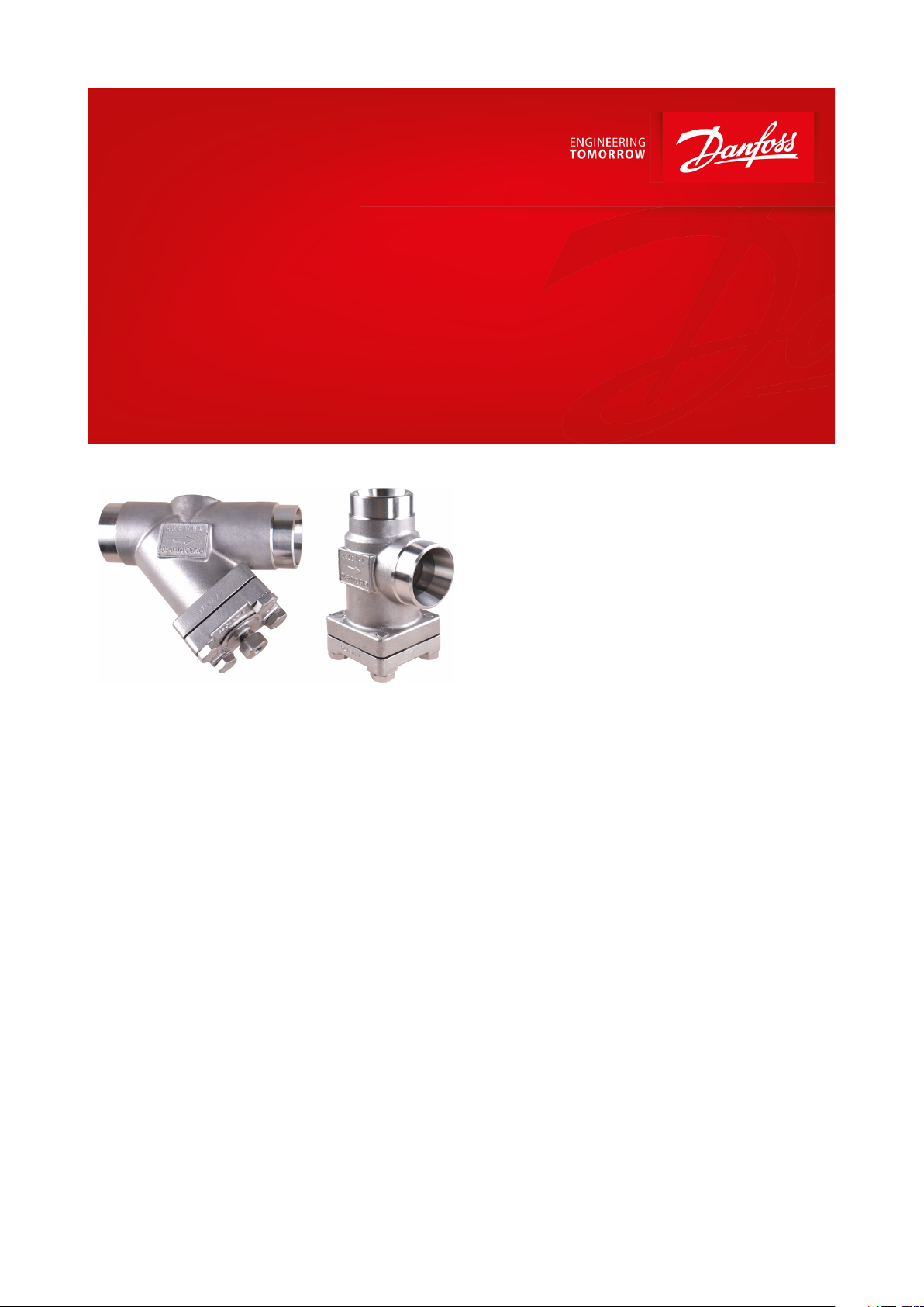
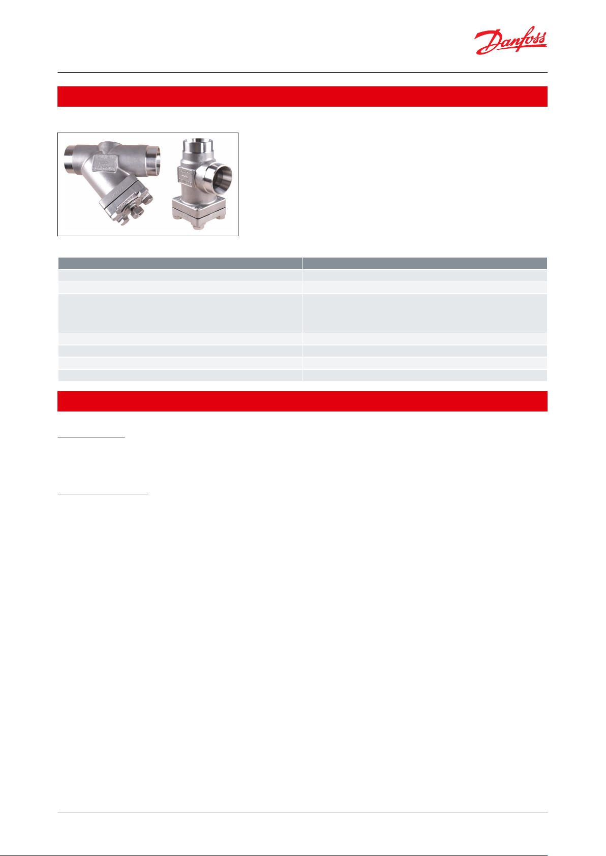
Strainer housing
Type FIA SS
Designed for highly demanding production environments,
where corrosion is a risk due to harsh environments
FIA SS strainers are a range of angle-way and
straight-way strainers which are carefully
designed to give favourable ow conditions.
The design makes the strainer easy to install,
and ensures quick strainer inspection and
cleaning.
FIA SS strainers are used ahead of automatic
controls, pumps, compressors etc., for initial
plant start-up and where permanent ltration
of the refrigerant is required. The strainer
reduces the risk of undesirable system
breakdowns and reduces wear and tear on
plant components.
In certain specic areas such as outdoor
applications and corrosive atmospheres, such
as coastal installations, there is a need for high
surface protection to prevent failure due to
corrosion.
Today's food safety standards often call for daily
treatment with detergents to protect against
bacteria growth, again producing a need for
high surface protection.
AI234986440196en-000901

Strainer housing, type FIA SS
Features
• Applicable to HCFC, HFC, R717 (Ammonia) and R744 (CO2) and all ammable refrigerants
• Designed to give favourable ow conditions
• Housing is made of special cold resistant stainless steel approved for low temperature operations
• Easy to disassemble for inspection and service
• Butt-weld DIN and ANSI connections
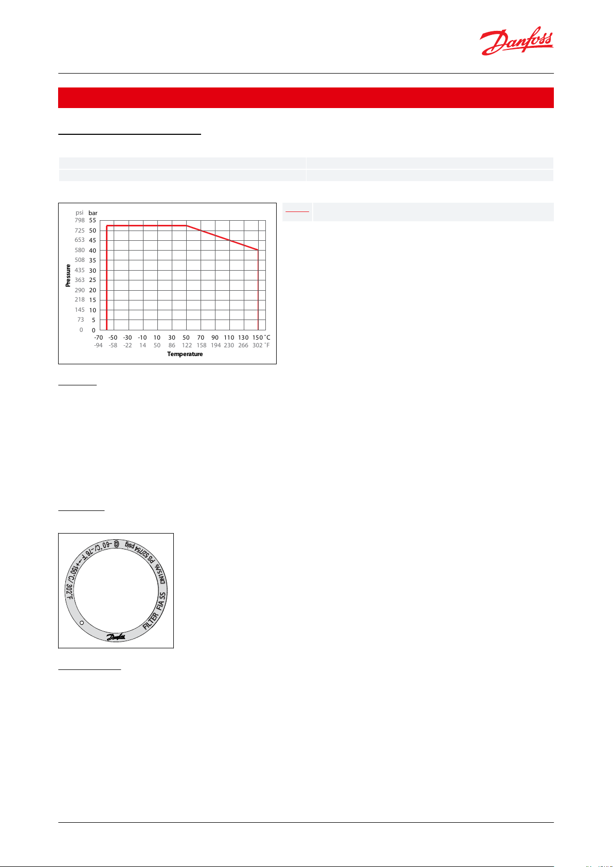
• Max. operating pressure:
◦ 52 bar (754 psig)
• Temperature range:
◦ -60 °C – 150 °C (-76 °F – 302 °F)
• Compact and light valves for easy handling and installation
• Classication: DNV, CRN, BV, EAC etc. To get an updated list of certication on the products please contact your
local Danfoss Sales Company
© Danfoss | Climate Solutions | 2021.03 AI234986440196en-000901 | 2
Description
Features
Valve body/connection material
Stainless steel
Equipment
Cover
Connection standard
EN 10220
DIN
ASME B 36.19M SCHEDULE 10
ASME B 36.19M SCHEDULE 40
Connection type
Butt weld
Max. working pressure [bar/psig]
52 bar/754 psig
Max. Temperature range
-60 °C – 150 °C (-76 °F – 302 °F)
Packing format
Single pack
Strainer housing, type FIA SS
Portfolio overview
Figure 1: FIA SS
Table 1: Portfolio overview
Media
Refrigerants
Applicable to HCFC, HFC, R717 (Ammonia), R744 (CO2) and all ammable refrigerants. For further information please
see installation guide for FIA SS.
New refrigerants
Danfoss products are continually evaluated for use with new refrigerants depending on market requirements.
When a refrigerant is approved for use by Danfoss, it is added to the relevant portfolio, and the R number of the
refrigerant (e.g. R513A) will be added to the technical data of the code number. Therefore, products for specic
refrigerants are best checked at store.danfoss.com/en/, or by contacting your local Danfoss representative.
© Danfoss | Climate Solutions | 2021.03 AI234986440196en-000901 | 3
-70
Pressure
-50 -30 -10 10 30 5 0 70 90 11 0 130 15 0
Temperature
-94 -58 -22 14 50 86 122 158 194 230 266 302
˚C
˚F
0
73
145
218
290
363
435
508
580
653
725
798
psi
0
5
10
15
20
25
30
35
40
45
50
55
bar
FIA SS DN15-DN65
Temperature range
-60 °C – 150 °C (-76 °F – 302 °F)
Max. operating pressure
52 bar (754 psig)
FF
II
LL
TT
EE
RR
FF
II
AA
SS
SS
DD
NN
11
55
//
½½
Strainer housing, type FIA SS
Product specication
Pressure and temperature
Table 2: Pressure and temperature
Figure 2: Pressure and temperature graph
Design
Materials
Housing
Made of stainless steel approved for low temperature operations
Strainer Insert
A lter grid and lter net of stainless steel ensure long element life. The lter net oers a very high degree of
cleanability
Marking
Figure 3: Example of marking ring, FIA SS
Installation
Installation/Maintenance
The strainer is designed to resist high internal pressures. However, the piping system in general should be designed
to avoid liquid traps and reduce the risk of hydraulic pressure caused by thermal expansion.
Install the strainer with the cover in downward position.
Danfoss recommends replacement/cleaning of the strainer when the dierential pressure loss >0.5 bar (7.3 psi) in
the liquid line and >0.05 bar (0.7 psi) in the suction line. The max. permissible dierential pressure is 1 bar (15 psi).
For further information refer to installation guide for FIA SS.
© Danfoss | Climate Solutions | 2021.03 AI234986440196en-000901 | 4

No.
Part
Material
DIN
ISO
ASTM
1
Housing
Stainless steel (FIA SS only)
GX5CrNi19-10
EN10213-4
AISI 304
2
Gasket
Fibre, Non-asbestos
3
Cover
Stainless steel (FIA SS only)
GX5CrNi19-10
EN10213-4
AISI 304
4
Bolts
Stainless steel
A2-70
A2-70
Type 308
5
Marking label
Aluminium
6
Filter element
Stainless steel
7
Pressure relief (screw) NPT
1
⁄4”
Stainless steel
3
3
4
4
7
8
5
7
5
8
6
6
2
2
1
1
No.
Part
Material
DIN
ISO
ASTM
1
Housing
Stainless steel (FIA SS only)
GX5CrNi19-10
EN10213-4
AISI 304
2
Gasket
Fibre, Non-asbestos
3
Cover
Stainless steel (FIA SS only)
GX5CrNi19-10
EN10213-4
AISI 304
4
Bolts
Stainless steel
A2-70
A2-70
Type 308
5
Marking label
Aluminium
6
Filter element
Stainless steel
7
Pressure relief (screw) NPT
1
⁄4”
Stainless steel
8
Packing washer
Aluminium
Strainer housing, type FIA SS
Material specication
FIA SS 15 - 40 (½ in. - 1½ in.)
Table 3: FIA SS 15 - 40 (½ in. - 1½ in.)
FIA SS 50 - 65 (2 in. - 21/2 in.)
Table 4: FIA SS 50 - 65 (2 in. - 2
1
⁄2 in.)
© Danfoss | Climate Solutions | 2021.03 AI234986440196en-000901 | 5

DIN
ANSI
ø
Connection
Size
mm/in.øDT
DIN
15mm21.3
2.3½in.
0.839
0.09120mm
26.9
2.3
3
⁄4
in.
1.059
0.09125mm
33.7
2.61in.
1.327
0.10332mm
42.4
2.6
1
1
⁄4
in.
1.669
0.10240mm
48.3
2.61½in.
1.902
0.10350mm
60.3
2.92in.
2.37
0.1165mm
76.1
2.92½in.30.11
Connection
Size
mm/in.øDT
ANSI
15mm21.3
2.8½in.
0.839
0.1120mm
26.9
2.9
3
⁄4
in.
1.06
0.1125mm
33.7
3.51in.
1.33
0.1432mm
42.4
3.6
1
1
⁄4
in.
1.67
0.1440mm
48.3
3.71½in.
1.9
0.15
Connection
Size
mm/in.øDT
ANSI
50mm60.3
2.82in.
2.37
0.1165mm733.12½in.
2.87
0.12
Strainer housing, type FIA SS
Connections
Available with the following connections:
• Butt-weld DIN (EN 10220)
◦ DN 15 - 65 (½ in. - 2½ in.)
• Butt-weld ANSI (B 36.19M)
◦ DN 15 - 65 (½ in. - 2½ in.)
Table 5: Butt-weld connections
Table 6: Butt-weld DIN (EN 10220)
Table 7: Butt-weld ANSI (B 36.19M, SCHEDULE 40)
Table 8: Butt-weld ANSI (B 36.19M, SCHEDULE 10)
Selection of strainer size
The mesh aperture size of the strainer must satisfy the requirements stated by the suppliers of the equipment to be
protected. The following recommendations of aperture size apply in general to refrigeration installations:
© Danfoss | Climate Solutions | 2021.03 AI234986440196en-000901 | 6

All lines
First start up
50μ
Liquid Lines
Ahead of pumps
500μ [38 mesh]
After pumps
150μ [100 mesh] / 250μ [72 mesh]
In front of AKVA valves
100μ [150 mesh]
Protection of automatic regulation equipment
Generally
150μ [100 mesh] / 250μ [72 mesh]
Sensitive equipment, e.g.suction regulators with low temperature
250μ [72 mesh]
Suction Lines
Ahead of screw compressor
250μ [72 mesh]
Ahead of piston compressor
150μ [100 mesh]
Connection size (DN)
FIA SS
μ
Mesh
Wire
[mm]
Wire
[in.]
Free space
[%]
Screen area
Plain elements
Pleated elements
cm2in2cm2in
2
15 - 20 (½” -
3
⁄4”)
100-0.068
0.0033525
3.9457.0
150
100
0.10
0.0043625
3.9457.0
250720.10
0.0045125
3.9457.0
500380.16
0.006
57.6253.9457.0
25 - 40 (1” - 1½”)
100-0.068
0.003357111160
25.0
150
100
0.10
0.004367111160
25.0
250720.10
0.004517111160
25.0
500380.16
0.006
57.67111
160
25.0
50 (2”)
100-0.068
0.003357111200
31.2
150
100
0.10
0.0043687
13.5
200
31.2
250720.10
0.0045187
13.5
200
31.2
500380.16
0.006
57.68713.5
200
31.2
65 (2½”)
150
100
0.10
0.00436127
19.7
305
47.6
250720.10
0.00451127
19.7
305
47.6
500380.16
0.006
57.6
127
19.7
305
47.6
DN
FIA SS angle - plain
lter net
FIA SS angle - pleated
lter net
μ100
μ150
μ250
μ500
μ150
μ250
μ500
15
3.3
3.4
3.5
3.7
4.2--206.9
7.1
7.3
7.7
8.8--2513.8
14.0
14.5
15.2
17.2
17.9
-3223.0
23.8
24.7
25.5
29.2
30.5
-4025.1
25.5
26.4
28.1
31.4
32.6
-5045.1
45.9
47.6
50.2
56.7
58.8
62.065-
56.1
57.8
60.4
69.3
71.4
74.6
Strainer housing, type FIA SS
Table 9: Recommendations of aperture size
NOTE:
(Use lter element with removable insert for FIA SS DN15 - 40 or separate lter bag for FIA SS DN 50 - 65. 50μ insert
should normally be removed after the rst 24 hours of operation)
NOTE:
Mesh is the number of threads per inch. μ (microns) is the distance between two threads (1μ = 1 /1000 mm).
Flow coecient (DIN/ANSI)
Table 10: Flow coecient (DIN/ANSI)
Kv values
Table 11: FIA SS angle
© Danfoss | Climate Solutions | 2021.03 AI234986440196en-000901 | 7

DN
FIA SS straight - plain lter net
FIA SS straight - pleated lter net
μ100
μ150
μ250
μ500
μ150
μ250
μ500
15
2.5
2.6
2.7
2.8
3.3--205.3
5.4
5.6
5.9
6.9--2510.5
10.7
11.1
11.6
13.8
14.5
-3217.6
18.2
18.9
19.5
23.9
24.7
-4019.2
19.5
20.2
21.5
25.5
26.4
-5034.5
35.1
36.4
38.4
45.9
47.6
50.265-
42.9
44.2
46.2
56.1
57.8
60.4
Strainer sizeAC
H
F
min.
Weight
FIA SS 15 - 20 (½" -
3
⁄4")
mm
45
1056068
1.1 kg
in.
1.77
4.13
2.36
2.68
2.4 lbs
FIA SS 25 - 40 (1" - 1½")
mm
55
1327095
1.7 kg
in.
2.17
5.20
2.76
3.74
3.7 lbs
FIA SS 50 (2")
mm
60
1327792
2.8 kg
in.
2.36
5.20
3.03
3.62
6.2 lbs
FIA SS 65 (2½")
mm
70
15290107
3.8 kg
in.
2.76
5.98
3.54
4.21
8.4 lbs
Strainer housing, type FIA SS
Table 12: FIA SS straight
Dimensions and weights
Angleway
Figure 4: Angleway
Table 13: Angleway
© Danfoss | Climate Solutions | 2021.03 AI234986440196en-000901 | 8

Strainer sizeAC
C
min.
H
E
F
min.
Weight
FIA SS 15 - 20 (½" -
3
⁄4")
mm
120991336020681.4 kg
in.
4.72
3.90
5.24
2.36
0.79
2.68
3.1 lbs
FIA SS 25 - 40 (1" - 1½")
mm
155
129
1777026952.4 kg
in.
6.10
5.08
6.97
2.76
1.02
3.74
5.3 lbs
FIA SS 50 (2")
mm
148
138
1847732923.5 kg
in.
5.83
5.43
7.24
3.03
1.26
3.62
7.7 lbs
FIA SS 65 (2½")
mm
176
165
2199040
107
5.3 kg
in.
6.93
6.50
8.62
3.54
1.57
4.21
11.7 lbs
Strainer housing, type FIA SS
Straightway
Figure 5: Straightway
Table 14: Straightway
© Danfoss | Climate Solutions | 2021.03 AI234986440196en-000901 | 9

Type
Size
FIA SS With‐
out Filter Ele‐
ment
Filter Element
100μ 150
mesh
Filter Element
150μ 100
mesh
Filter Element
250μ 72 mesh
Filter Element
500μ 38 mesh
Pleated lter
element 150μ
100 mesh
Pleated lter
element 250μ
72 mesh
Pleated lter
element 500μ
38 mesh
mm
in.
Butt-weld DIN (EN 10220) - Angleway
FIA SS 15 D ANG
15½148B5295
148H3122
148H3124
148H3126
148H3128
148H3303
148H3363
-
FIA SS 20 D ANG
20¾148B5383
FIA SS 25 D ANG
251148B5492
148H3123
148H3125
148H3127
148H3129
148H3304
148H3269
-
FIA SS 32 D ANG
321¼148B5587
FIA SS 40 D ANG
401½148B5666
FIA SS 50 D ANG
502148B5757
148H3157
148H3130
148H3138
148H3144
148H3179
148H3184
148H3189
FIA SS 65 D ANG
652½148B5851
-
148H3131
148H3139
148H3145
148H3180
148H3185
148H3190
Butt-weld ANSI (B 36.19M SCHEDULE 10) - Angleway
FIA SS 65 A10
ANG
652½148B6498
-
148H3131
148H3139
148H3145
148H3180
148H3185
148H3190
Type
Size
FIA SS With‐
out Filter Ele‐
ment
Filter Element
100μ 150
mesh
Filter Element
150μ 100
mesh
Filter Element
250μ 72 mesh
Filter Element
500μ 38 mesh
Pleated
lter
element 150μ
100 mesh
Pleated
lter
element 250μ
72 mesh
Pleated
lter
element 500μ
38 mesh
mm
in.
Butt-weld DIN (EN 10220) - Straightway
FIA SS 15 D STR
15½148B5296
148H3122
148H3124
148H3126
148H3128
148H3303
148H3363
-
FIA SS 20 D STR
20¾148B5384
FIA SS 25 D STR
251148B5493
148H3123
148H3125
148H3127
148H3129
148H3304
148H3269
-
FIA SS 32 D STR
321¼148B5588
FIA SS 40 D STR
401½148B5667
FIA SS 50 D STR
502148B5758
148H3157
148H3130
148H3138
148H3144
148H3179
148H3184
148H3189
FIA SS 65 D STR
652½148B5852
-
148H3131
148H3139
148H3145
148H3180
148H3185
148H3190
Butt-weld ANSI (B 36.19M SCHEDULE 40) - Straightway
FIA SS 15 A40
STR
15½148B6493
148H3122
148H3124
148H3126
148H3128
148H3303
148H3363
-
FIA SS 20 A40
STR
20¾148B6494
FIA SS 25 A40
STR
251148B6495
148H3123
148H3125
148H3127
148H3304
148H3304
148H3269
-
FIA SS 32 A40
STR
321¼148B6496
FIA SS 40 A40
STR
401½148B6497
Butt-weld ANSI (B 36.19M SCHEDULE 10) - Straightway
FIA SS 50 A10
STR
502148B5758
148H3157
148H3130
148H3138
148H3144
148H3179
148H3184
148H3189
FIA SS 65 A10
STR
652½148B6499
-
148H3131
148H3139
148H3145
148H3180
148H3185
148H3190
Strainer housing, type FIA SS
Ordering
The table below is used to identify the strainer required. Please note that you have to order FIA SS strainer without
element, a strainer element and accessories.
Example:
FIA SS 50 D ANG + FIA-X 50 150μ Strainer Element + Filter Bag = 148H5757 + 148H3130 + 148H3150
Butt-weld Angleway
Table 15: Butt-weld Angleway
Butt-weld Straightway
Table 16: Butt-weld Straightway
D = Butt-weld DIN
A = Butt-weld ANSI
ANG = Angleway
STR = Straightway
© Danfoss | Climate Solutions | 2021.03 AI234986440196en-000901 | 10

Part
Accessory for
Code number
Filter element μ150 with removable element μ50 for
the rst start up
FIA SS 15 - 20
148H3301
FIA SS 25 - 40
148H3302
Part
Accessory for
Code number
Filter bag
FIA SS 50
148H3150
FIA SS 65
148H3151
Part
Accessory for
Code number
Blind nut with gasket
FIA SS 50 - 65
48H3450
Strainer housing, type FIA SS
Accessories
Table 17: Filter element μ150
Table 18: Filter bag
Table 19: Blind nut with gasket
© Danfoss | Climate Solutions | 2021.03 AI234986440196en-000901 | 11

Nominal bore
DN ≤ 25 (1 in.)
DN 32 - 65 mm (1 1/4 in. - 2½ in.)
Classied for
Fluid group I
Category
Article 3, paragraph 3
II
FIA SS strainers are approved in accordance with the European standard specied in the Pressure Equipment Directive and are CE
marked.
For further details / restrictions - see Installation guide.
File name
Document type
Document topic
Approval authority
BV 03709-E0 BV
Marine - Safety Certicate
BV
033F0691.AD
Manufacturers Declaration
RoHS
Danfoss
DNV GL TAP000000S Rev. 1
Marine - Safety Certicate
DNV GL
033F0685.AJ
EU Declaration
EMCD/PED
Danfoss
033F0686.AG
Manufacturers Declaration
PED
Danfoss
033F0453.AD
Manufacturers Declaration
ATEX
Danfoss
CRN.0C16578.523467890YTN
Pressure - Safety Certicate
CRN
TSSA
Strainer housing, type FIA SS
Certicates, declarations, and approvals
The list contains all certicates, declarations, and approvals for this product type. Individual code number may have
some or all of these approvals, and certain local approvals may not appear on the list.
Some approvals may change over time. You can check the most current status at danfoss.com or contact your local
Danfoss representative if you have any questions.
Table 20: Compliance table FIA 250-300
Table 21: Pressure Equipment Directive (PED)
Table 22: Valid Approvals
© Danfoss | Climate Solutions | 2021.03 AI234986440196en-000901 | 12

Online support
Danfoss oers a wide range of support along with our products, including digital product information, software,
mobile apps, and expert guidance. See the possibilities below.
The Danfoss Product Store
The Danfoss Product Store is your one-stop shop for everything product related—no matter where
you are in the world or what area of the cooling industry you work in. Get quick access to essential
information like product specs, code numbers, technical documentation, certications, accessories,
and more.
Start browsing at store.danfoss.com.
Find technical documentation
Find the technical documentation you need to get your project up and running. Get direct access to
our ocial collection of data sheets, certicates and declarations, manuals and guides, 3D models
and drawings, case stories, brochures, and much more.
Start searching now at www.danfoss.com/en/service-and-support/documentation.
Danfoss Learning
Danfoss Learning is a free online learning platform. It features courses and materials specically
designed to help engineers, installers, service technicians, and wholesalers better understand the
products, applications, industry topics, and trends that will help you do your job better.
Create your Danfoss Learning account for free at www.danfoss.com/en/service-and-support/learning.
Get local information and support
Local Danfoss websites are the main sources for help and information about our company and
products. Find product availability, get the latest regional news, or connect with a nearby expert—all
in your own language.
Find your local Danfoss website here: www.danfoss.com/en/choose-region.
Spare Parts
Get access to the Danfoss spare parts and service kit catalog right from your smartphone. The app
contains a wide range of components for air conditioning and refrigeration applications, such as
valves, strainers, pressure switches, and sensors.
Download the Spare Parts app for free at www.danfoss.com/en/service-and-support/downloads.
Coolselector®2 - nd the best components for you HVAC/R system
Coolselector®2 makes it easy for engineers, consultants, and designers to nd and order the best
components for refrigeration and air conditioning systems. Run calculations based on your operating
conditions and then choose the best setup for your system design.
Download Coolselector®2 for free at coolselector.danfoss.com.
Danfoss can accept no responsibility for possible errors in catalogues, brochures and other printed material. Danfoss reserves the right to alter its
products without notice. This also applies to products already on order provided that such alterations can be made without subsequential
changes being necessary in specications already agreed. All trademarks in this material are property of the respective companies. Danfoss and
the Danfoss logotype are trademarks of Danfoss A/S. All rights reserved.
© Danfoss | Climate Solutions | 2021.03 AI234986440196en-000901 | 13
 Loading...