

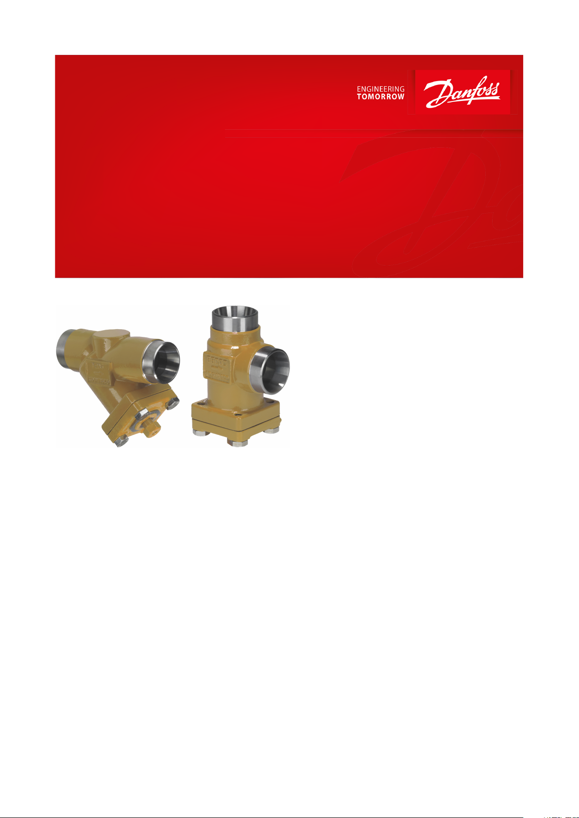
Data Sheet
Strainer housing
Type FIA 65
Reliable ltration up to 65 bar
FIA strainers are a range of angleway and
straightway strainers, which are carefully
designed to give favourable ow conditions.
The design makes the strainer easy to install,
and ensures quick strainer inspection and
cleaning.
FIA strainers are used ahead of automatic
controls, pumps, compressors etc., for initial
plant start-up and where permanent ltration
of the refrigerant is required. The strainer
reduces the risk of undesirable system
breakdowns and reduces wear and tear on
plant components.
FIA strainers are equipped with a screen mesh
of stainless steel, available in sizes 100, 150, 250
and 500μ (microns*), (US 150, 100, 72, 38
mesh*).
* Mesh is the number of threads per inch. μ
(microns) is the distance between two threads
(1μ = 1 /1000 mm).
AI367729235609en-000101
Strainer housing, type FIA 65
Features
• Modular Concept:
◦ Each valve housing is available with DIN and ANSI butt weld connection and in several dierent sizes.
◦ Possible to convert FIA strainers to any other product in the SVL family (Shut-o valve, regulating valve, check &
stop valve or check valve) just by replacing the complete top part.
• Quick and easy maintenance. Replacement of top part does not require welding.
• Filter net of stainless steel mounted direct without extra gaskets means easy servicing.
• Two types of strainer inserts are available:
◦ A plain insert made of stainless steel.
◦ A pleated insert (DN 15-200) with extra large surface, which ensures long intervals between cleaning and low
pressure drop.
• FIA 15-40 (½ – 1 ½ in.):
A special insert (50μ) can be used in combination with a standard version when cleaning a plant during
commissioning.
• FIA 50-200 (2 - 8 in.):
A large capacity lter bag (50μ) can be inserted for cleaning plant during commissioning.
• FIA 65-200 (2½ - 8 in.) can be equipped with a magnetic insert for detention of iron particles and other magnetic
particles.
• Each strainer clearly marked with type, size and performance range
• Housing and bonnet of low temperature steel in accordance with the requirements of the Pressure Equipment
Directive and those of other international classication authorities
• Classication: DNV, CRN, BV, EAC etc. To get an updated list of certication on the products please contact your
local Danfoss Sales Company.
• Equipped with 42CrMo5 bolts to withstand high pressure.
Media
Refrigerants
Applicable to HCFC, HFC, R717 (Ammonia), R744 (CO₂) and ammable refrigerants.
For further information refer to the product instruction for FIA.
New refrigerants
Danfoss products are continually evaluated for use with new refrigerants depending on market requirements.
When a refrigerant is approved for use by Danfoss, it is added to the relevant portfolio, and the R number of the
refrigerant (e.g. R513A) will be added to the technical data of the code number. Therefore, products for specic
refrigerants are best checked at store.danfoss.com/en/, or by contacting your local Danfoss representative.
© Danfoss | Climate Solutions | 2021.04 AI367729235609en-000101 | 2
Description
Values
Temperature range
-60 °C /+150 °C (-76 °F /+302 °F)
Max working pressure
65 bar (943 psig)
OD
T
Size
ODTOD
T
kv-angle
kv-straight
Cv-angle
Cv-straight
mm
in.mmmm
in.
in.
m3/h
m3/h
USgal/min
USgal/min
6¼13.5
2.3
0.531
0.091
2.9
2.0
3.4
2.410⅜
17.2
2.3
0.677
0.091
4.5
3.2
5.2
3.615½
21.3
2.3
0.839
0.091
7.0
4.9
8.1
5.720¾
26.9
2.3
1.059
0.091
14.6
10.2
16.9
11.8251
33.7
2.6
1.327
0.103
24.8
17.4
28.8
20.2321¼
42.4
2.6
1.669
0.102
42.6
29.8
49.4
34.6401½
48.3
2.6
1.902
0.103
45.2
31.6
52.4
36.7502
60.3
2.9
2.37
0.1180659376652½
76.1
2.930.11
12097140
113803
88.9
3.2
3.50
0.13
182
152
211
176
1004114.3
3.6
4.50
0.14
313
278
363
323
1255139.7
4.0
5.50
0.16
514
470
596
545
1506168.3
4.5
6.63
0.18
785
597
911
693
2008219.1
6.3
8.63
0.25
1168
1024
1355
1188
OD
T
Size
ODTOD
T
k
v
-angle
k
v
-straight
C
v
-angle
C
v
-straight
mm
in.mmmm
in.
in.
m
3
/h
m
3
/h
USgal/min
USgal/min
6¼13.5
3.0
0.531
0.118
2.9
2.03
3.4
2.410⅜
17.2
3.2
0.677
0.126
4.5
3.15
5.2
3.615½
21.3
3.7
0.839
0.146
7.0
4.9
8.1
5.720¾
26.9
4.0
1.059
0.158
14.6
10.2
16.9
11.8251
33.7
4.6
1.327
0.181
24.8
17.4
28.8
20.2321¼
42.4
4.9
1.669
0.193
42.6
29.8
49.4
34.6401½
48.3
5.1
1.902
0.201
45.2
31.6
52.4
36.7
Strainer housing, type FIA 65
Product specication
Pressure and temperature data
Table 1: Temperature and pressure
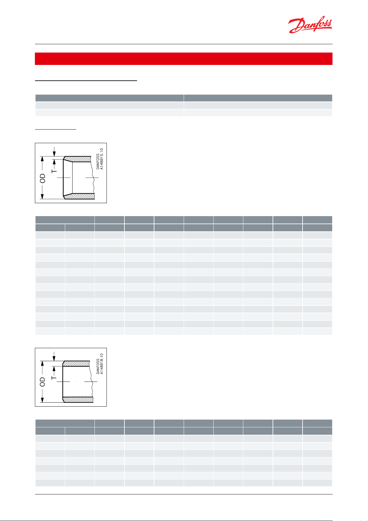
Connections
Figure 1: DIN
Table 2: Butt-weld DIN (EN 10220)
Figure 2: ANSI
Table 3: Butt-weld ANSI (B 36.10 Schedule 80)
© Danfoss | Climate Solutions | 2021.04 AI367729235609en-000101 | 3
Size
ODTOD
T
kv-angle
kv-straight
Cv-angle
Cv-straight
mm
in.mmmm
in.
in.
m3/h
m3/h
USgal/min
USgal/min
50260.3
3.9
2.37
0.1580659376652½
73.0
5.2
2.87
0.20
12097140
113803
88.9
5.5
3.50
0.22
182
152
211
176
1004114.3
6.0
4.50
0.24
313
278
363
323
1255141.3
6.6
5.56
0.26
514
470
596
545
1506168.3
7.1
6.63
0.28
785
597
911
693
2008219.1
8.2
8.63
0.32
1168
1024
1355
1188
Size
IDLOD
T
kv-angle
kv-straight
Cv-angle
Cv-straight
mm
in.mmmmmmmm
m3/h
m3/h
USgal/min
USgal/min
6¼6
7.7
12.7
3.35
2.9
2.0
3.4
2.410⅜108
15.88
2.94
4.5
3.2
5.2
3.615½168
21.3
2.65
7.0
4.9
8.1
5.720¾2211
26.9
2.45
14.6
10.2
16.9
11.82512811
33.7
2.85
24.8
17.4
28.8
20.2321¼3515
42.4
3.7
42.6
29.8
49.4
34.6401½4215
48.3
3.15
45.2
31.6
52.4
36.75025413.5
60.3
3.1580659376652½6413.5734.5
12097140
113803
76.11588.9
6.4
182
152
211
176
1004108
17.5
1185313
278
363
323
SizeIDLODT
k
v
-angle
k
v
-straight
C
v
-angle
C
v
-straight
in.mmmmmmmm
m
3
/h
m
3
/h
USgal/min
USgal/min
¼
6.35
7.7
12.7
3.18
2.9
2.0
3.4
2.4⅜9.53815.88
3.18
4.5
3.2
5.2
3.6⅝15.88821.3
2.71
7.0
4.9
8.1
5.7⅞22.231126.9
2.34
14.6
10.2
16.9
11.8
1⅛28.581133.7
2.56
24.8
17.4
28.8
20.2
1⅜34.931542.4
3.74
42.6
29.8
49.4
34.6
1⅝41.281548.3
3.51
45.2
31.6
52.4
36.7
2⅛54
13.5
60.3
3.1580659376
Strainer housing, type FIA 65
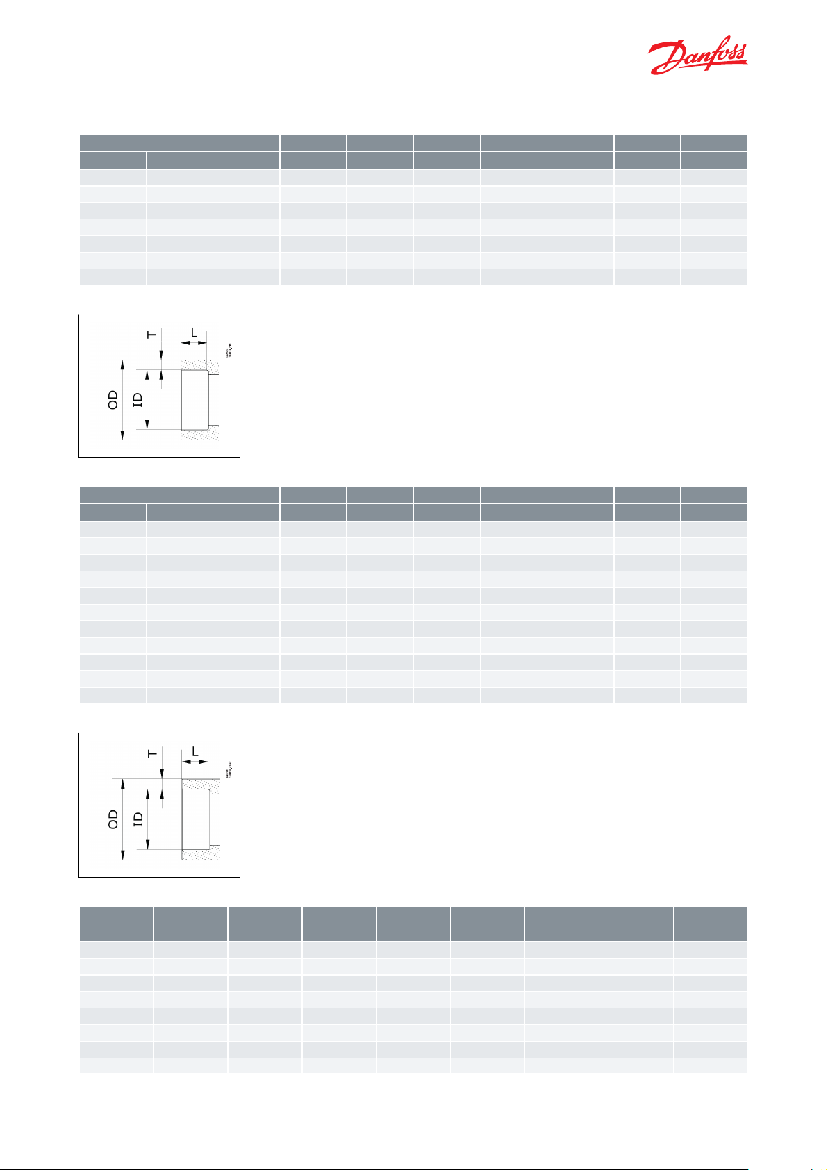
Table 4: Butt-weld ANSI (B 36.10 Schedule 40)
Figure 3: SD (DIN )
Table 5: Socket-Brazing DIN ( EN 1254-5)
Figure 4: SA (ASME)
Table 6: Socket-Brazing ASME (ASME B16.50)
© Danfoss | Climate Solutions | 2021.04 AI367729235609en-000101 | 4

SizeIDLODT
kv-angle
kv-straight
Cv-angle
Cv-straight
in.mmmmmmmm
m3/h
m3/h
USgal/min
USgal/min
2⅝
66.7
13.5
76.1
4.70
12097140
1133⅛79.381588.9
4.76
182
152
211
1764⅛104.78
17.5
114.3
4.76
313
278
363
323
Copper pipe diameter
Tolerance
≥3mm up to ≤18 mm
±0,04 mm
Over 18 mm up to ≤28 mm
±0,05 mm
Over 28 mm up to ≤54 mm
±0,06 mm
Over 54 mm up to ≤76,1 mm
±0,07 mm
Over 76,1 mm up to ≤88,9 mm
±0,07 mm
Over 88,9 mm up to ≤108 mm
±0,07 mm
Size
[DN]
Parts program
Service
kit
(1)
Complete valve
Housing
Top complete
O-ring kit
for
SVA (cap)
FIA
ANG
STR
SVA-
S
(cap)
SVA-
L
(cap)
SCA-XCHV-XREG-SAREG-
SB
FIA
R717
Heat
Pump
R1270
Pro‐
py‐
lene
ANG
STR
ANG
STR
DIN
AN‐
SI
SDSADIN
AN‐
SI
SDSADIN
AN‐
SI
DIN
AN‐
SI
DIN
AN‐
SI
DIN
AN‐
SI
6xxxxxxxxxxx10xxxxxxxxxxxxxxx15xxxxxxxxxxxxxxxxxxx20xxxxxxxxxxxxxxxxxxx25xxxxxxxxxxxxxxxxxxx32xxxxxxxxxxxxxxxxxxx40xxxxxxxxxxxxxxxxxxx50xxxxxxxxxxxxxxxxx65xxxxxxxxxxxxxxxxx80xxxxxxxxxxxxxxxx
100xxxxxxxxxxxxxxxx
125xxxxxxxxxxxx
150xxxxxxxx
200xxxxxxxx
Strainer housing, type FIA 65
The design ts with all copper pipes having following tolerance to the nominal diameter.
Table 7: Tolerance for nominal diameter
Table 8: Available SVL products for 65 bar (943 psi)
(1)
(1)
To be used for SCA-X, CHV-X (all sizes) and REG-SA/SB (sizes 10 to 40).
To be used for SCA-X, CHV-X (all sizes) and REG-SA/SB (sizes 10 to 40).
x = Available
Design
Strainer Insert
A lter grid and lter net of stainless steel ensure long element life. The lter net oers a very high degree of
cleanability.
Housing
The strainer housing is made of special, cold resistant steel.
Installation/Maintenance
The strainer is designed to resist high internal pressures. However, the piping system in general should be designed
to avoid liquid traps and reduce the risk of hydraulic pressure caused by thermal expansion.
Install the strainer with the cover in downward position.
Danfoss recommends replacement/cleaning of the strainer when the dierential pressure loss >0.5 bar (7.3 psi) in
the liquid line and >0.05 bar (0.7 psi) in the suction line. The max. permissible dierential pressure is 1 bar (15 psi).
© Danfoss | Climate Solutions | 2021.04 AI367729235609en-000101 | 5

P
S
6
5
/
9
4
3
p
s
i
g
S
T
R
A
I
N
E
R
F
I
A
D
N
8
0
/
3
”
@
–
6
0
°
C
\
–
7
6
°
F
→
1
5
0
°
C
\
3
0
2
°
F
Danfoss
M148G0020
First start up:
(Use strainer element with removable insert for FIA DN15-40 or separate lter bag
for FIA DN 50-200. 50μ insert should normally
be removed after the rst 24 hours of operation)
50μ
Ahead of pumps:
500μ [38 mesh]
After pumps:
150μ [100 mesh] / 250μ [72 mesh]
In front of AKVA valves:
100μ [150 mesh]
Generally
150μ [100 mesh] / 250μ [72 mesh]
Sensitive equipment, e.g.
suction regulators with low temperature
250μ [72 mesh]
Ahead of screw compressor
250μ [72 mesh]
Ahead of piston compressor
150μ [100 mesh]
Connection
size (DN)
μ
Mesh
Wire
Wire
Free space
Screen area
Plain elements
Pleated elements
FIAmmin.
%
cm2in2cm2in
2
15 - 20
(½” - ¾”)
100
0.068
0.0033525
3.9457.0
150
100
0.10
0.0043625
3.9457.0
250720.10
0.0045125
3.9457.0
500380.16
0.006
57.6253.9457.0
25 - 40
(1” - 1½”)
100
0.068
0.003357111160
25.0
150
100
0.10
0.004367111160
25.0
250720.10
0.004517111160
25.0
500380.16
0.006
57.67111
160
25.0
Strainer housing, type FIA 65
For further information refer to installation instruction for FIA.
Figure 5: Example of marking ring, FIA
Selection of strainer size
The mesh aperture size of the strainer must satisfy the requirements stated by the suppliers of the equipment to be
protected.
The following recommendations of aperture size apply in general to refrigeration installations:
Table 9: All lines
Table 10: Liquid Lines
Table 11: Protection of automatic regulation equipment
Table 12: Suction Lines
NOTE:
Mesh is the number of threads per inch. μ (microns) is the distance between two threads (1μ = 1 /1000 mm).
Table 13: Flow coecient (DIN/ANSI)
© Danfoss | Climate Solutions | 2021.04 AI367729235609en-000101 | 6

Connection
size (DN)
μ
Mesh
Wire
Wire
Free space
Screen area
Plain elements
Pleated elements
FIAmmin.
%
cm2in2cm2in
2
50 (2”)
100
0.068
0.003357111200
31.2
150
100
0.10
0.0043687
13.5
200
31.2
250720.10
0.0045187
13.5
200
31.2
500
0.16
0.006
57.68713.5
200
31.2
65 (2½”)
150
100
0.10
0.00436127
19.7
305
47.6
250720.10
0.00451127
19.7
305
47.6
500
0.16
0.006
57.6
127
19.7
305
47.6
80 (3”)
150
100
0.10
0.00436205
31.8
450
70.2
250720.10
0.00451205
31.8
450
70.2
500380.16
0.006
57.6
205
31.8
450
70.2
100 (4”)
150
100
0.10
0.00436370
57.4
790
123.2
250720.10
0.00451370
57.4
790
123.2
500380.16
0.006
57.6
370
57.4
790
123.2
125 (5”)
150
100
0.10
0.00436510
79.1
1105
172.4
250720.10
0.00451510
79.1
1105
172.4
500380.16
0.006
57.6
510
79.1
1105
172.4
150 (6”)
150
100
0.10
0.00436726
112.5
1600
249.6
250720.10
0.00451726
112.5
1600
249.6
500380.16
0.006
57.6
726
112.5
1600
249.6
200 (8”)
150
100
0.10
0.004361315
203.8
2900
453.1
250720.10
0.004511315
203.8
2900
453.1
500380.16
0.006
57.6
1315
203.8
2900
453.1
DN
FIA angle - plain lter net
FIA angle - pleated lter net
μ100
μ150
μ250
μ500
μ150
μ250
μ500
15
3.3
3.4
3.5
3.7
4.2206.9
7.1
7.3
7.7
8.82513.8
14.0
14.5
15.2
17.2
17.93223.0
23.8
24.7
25.5
29.2
30.54025.1
25.5
26.4
28.1
31.4
32.65045.1
45.9
47.6
50.2
56.7
58.8
62.06556.1
57.8
60.4
69.3
71.4
74.680104.6
108.0
113.1
129.2
133.4
139.7
100
162.4
167.5
176.0
200.6
206.9
217.4
125
275.4
283.9
298.4
340.2
350.7
368.6
150
362.1
373.2
391.9
447.3
462.9
200
572.9
590.8
620.5
704.9
730.0
DN
FIA straight - plain lter net
FIA straight - pleated lter net
μ100
μ150
μ250
μ500
μ150
μ250
μ500
15
2.5
2.6
2.7
2.8
3.3205.3
5.4
5.6
5.9
6.92510.5
10.7
11.1
11.6
13.8
14.53217.6
18.2
18.9
19.5
23.9
24.74019.2
19.5
20.2
21.5
25.5
26.45034.5
35.1
36.4
38.4
45.9
47.6
50.26542.9
44.2
46.2
56.1
57.8
60.48080.0
82.6
86.5
104.6
108.0
113.1
100
124.2
128.1
134.6
162.4
167.5
176.0
125
210.6
217.1
228.2
275.4
283.9
298.4
150
276.9
285.4
299.7
362.1
374.0
200
438.1
451.8
474.5
570.8
587.3
Strainer housing, type FIA 65
Table 14: kv values for FIA angle - plain lter net/pleated lter net
Table 15: kv values for FIA straight - plain lter net/pleated lter net
© Danfoss | Climate Solutions | 2021.04 AI367729235609en-000101 | 7

1
2
3
5
7
4
6
6
5
7
4
3
2
1
No.
Part
Material
DIN
ISO
ASTM
1
Housing
Steel
G20Mn5QT, 10213-3
P285QH+QT, 10222-4
LCC, A352
LF2, A350
2
Gasket
Fibre, Non-asbestos
3
Cover
Steel
P285QH EN10222-4
P275NL1 or 2 EN10028-3
LF2, A350
A, A662
4
Bolts
Stainless steel
A2-70
A2-70
Type 308
5
Marking label
Aluminium
6
Strainer insert
Stainless steel
7
Pressure relief screw NPT ¼”
Stainless steel
1
2
3
4
2
7
8
5
6
1
3
4
6
5
8
7
No.
Part
Material
DIN
ISO
ASTM
1
Housing
Steel
G20Mn5QT, 10213-3
P285QH+QT, 10222-4
LCC, A352
LF2, A350
2
Gasket
Fibre, Non-asbestos
3
Cover
Steel
P285QH EN10222-4
P275NL1 or 2 EN10028-3
LF2, A350
A, A662
4
Bolts
Stainless steel
A2-70
A2-70
Type 308
5
Marking label
Aluminium
6
Strainer insert
Stainless steel
7
Pressure relief screw G½”
Stainless steel
8
(1)
Packing washer
Aluminium
Strainer housing, type FIA 65
Material specication
Figure 6: FIA 15 - 40 (½ in. - 1 ½ in.)
Table 16: FIA 15 - 40 (½ in. - 1 ½ in.)
Figure 7: FIA 50 - 200 (2 in. - 8 in.)
Table 17: FIA 50 - 200 (2 in. - 8 in.)
(1)
(1)
pos 8 used in FIA 50-200
pos 8 used in FIA 50-200
© Danfoss | Climate Solutions | 2021.04 AI367729235609en-000101 | 8

A
Straightway
E
C
Cmin.
Fmin.
H
Angleway
H
A
C
A
Fmin.
Strainer size
ACH
F
min.
Weight
FIA 15-20
(½" - ¾")
mm451056068
1.1 kg
in.
1.77
4.13
2.36
2.68
2.4 lbs
FIA 25-40
(1" - 1½")
mm551327095
1.7 kg
in.
2.17
5.20
2.76
3.74
3.7 lbs
FIA 50
(2")
mm601327792
2.8 kg
in.
2.36
5.20
3.03
3.62
6.2 lbs
FIA 65
(2½")
mm7015290107
3.8 kg
in.
2.76
5.98
3.54
4.21
8.4 lbs
Strainer size
A
C
C
min.
H
E
F
min.
Weight
FIA 15-20
(½" - ¾")
mm
120991336020681.4 kg
in.
4.72
3.90
5.24
2.36
0.79
2.68
3.1 lbs
FIA 25-40
(1" - 1½")
mm
155
129
1777026952.4 kg
in.
6.10
5.08
6.97
2.76
1.02
3.74
5.3 lbs
FIA 50
(2")
mm
148
138
1847732923.5 kg
in.
5.83
5.43
7.24
3.03
1.26
3.62
7.7 lbs
FIA 65
(2½")
mm
176
165
2199040
107
5.3 kg
in.
6.93
6.50
8.62
3.54
1.57
4.21
11.7 lbs
Strainer housing, type FIA 65
Dimensions and weights
Figure 8: FIA 15 - 65 Angleway/Straightway dimensions
Table 18: Angleway
Table 19: Straightway
NOTE:
Specied weights are approximate values only.
© Danfoss | Climate Solutions | 2021.04 AI367729235609en-000101 | 9

Danfoss
M148G0015_1
Danfoss
M148G0014_1
Fmin.
A
C
øH
øH
Cmin
C
E
A
Fmin.
Angleway Straightway
Strainer size
ACøH
F
min.
Weight
FIA 80
(3")
mm90189
129
133
7.3 kg
in.
3.54
7.44
5.08
5.24
16.1 lbs
FIA 100
(4")
mm
106
223
156
163
11.9 kg
in.
4.17
8.78
6.14
6.42
26.2 lbs
FIA 125
(5")
mm
128
268
192
190
21.2 kg
in.
5.04
10.6
7.56
7.48
46.7 lbs
FIA 150
(6")
mm
145
303
219
223
30.5 kg
in.
5.71
11.93
8.62
8.78
67.2 lbs
FIA 200
(8")
mm
180
372
276
280
68 kg
in.
7.09
14.65
10.87
11.02
150 lbs
Strainer size
A
C
C
min.
øH
E
F
min.
Weight
FIA 80
(3")
mm
216
204
271
12948133
8.6 kg
in.
8.50
8.03
10.67
5.08
1.89
5.24
19 lbs
FIA 100
(4")
mm
264
256
337
15660163
14.9 kg
in.
10.39
10.08
13.27
6.14
2.36
6.42
32.8 lbs
FIA 125
(5")
mm
322
313
408
19274190
26.9 kg
in.
12.68
12.32
16.06
7.56
2.91
7.48
59.3 lbs
FIA 150
(6")
mm
370
370
482
21991223
51 kg
in.
14.57
14.57
18.98
8.62
3.58
8.78
112 lbs
FIA 200
(8")
mm
464
465
605
276
117
280
95 kg
in.
18.27
18.31
23.82
10.87
4.61
11.02
209 lbs
Strainer housing, type FIA 65
Figure 9: FIA 80 - 200 Angleway/Straightway
Table 20: Angleway
Table 21: Straightway
NOTE:
Specied weights are approximate values only.
© Danfoss | Climate Solutions | 2021.04 AI367729235609en-000101 | 10

FIA size
Strainer insert
100μ 150 mesh
Strainer insert
150μ 100 mesh
Strainer insert
250μ 72 mesh
Strainer insert
500μ 38 mesh
Pleated Strainer
insert 150μ 100
mesh
Pleated Strainer
insert 250μ 72
mesh
Pleated Strainer
insert 500μ 38
mesh
mm
in.
15
½
148H3122
148H3124
148H3126
148H3128
148H3303
148H3363
-
20¾25
1
148H3123
148H3125
148H3127
148H3129
148H3304
148H3269
-
321¼401½502148H3157
148H3130
148H3138
148H3144
148H3179
148H3184
148H3189
652½-
148H3131
148H3139
148H3145
148H3180
148H3185
148H3190
803-
148H3119
148H3120
148H3121
148H3181
148H3186
148H3191
1004-
148H3132
148H3140
148H3146
148H3182
148H3187
148H3192
1255-
148H3133
148H3141
148H3147
148H3183
148H3188
148H3193
1506-
148H3134
148H3142
148H3148
148H3226
148H3293
(1)
-
2008-
148H3135
148H3143
148H3149
148H3297
148H3294
(1)
-
Part
Accessory for
Code number
Magnet insert
FIA 65-100
148H3447
FIA 125-200
148H3448
Strainer element μ150 with removable element μ50
for the rst start up
FIA 15-20
148H3301
FIA 25-40
148H3302
Filter bag
FIA 50
148H3150
FIA 65
148H3151
FIA 80
148H3152
FIA 100
148H3153
FIA 125
148H3154
FIA 150
148H3155
FIA 200
148H3156
Purge valve complete
FIA 50 - 300
148B3745
Blind nut with gasket
148H3450
Strainer housing, type FIA 65
Ordering
Strainer element
Please note that you have to order FIA strainer without element, a strainer element and accessories.
Table 22: Strainer elements
(1)
(1)
60 mesh
60 mesh
Accessories
Table 23: Accessories
© Danfoss | Climate Solutions | 2021.04 AI367729235609en-000101 | 11

File name
Document type
Approval authority
RU Д-DK.БЛ08.B.00828_19
EAC Declaration
EAC
0045 202 1204 Z 00354 19 D 001(00)
Pressure - Safety Certicate
TÜV
03709-F0 BV
Marine - Safety Certicate
BV
RU Д-DK.РА01.B.32851_20
EAC Declaration
EAC
RU C-DK.БЛ08.B.01095_20
Pressure - Safety Certicate
EAC
TAP000000S Rev. 1
Marine - Safety Certicate
DNV GL
EU 033F0685.AK
EU Declaration
Danfoss
MD 033F0691.AE
Manufacturers Declaration
Danfoss
MD 033F0686.AH
Manufacturers Declaration
Danfoss
0045 202 1204 Z 00355 19 D 001(00)
Pressure - Safety Certicate
TÜV
033F0453.AD
Manufacturers Declaration
Danfoss
19.10048.266
Marine - Safety Certicate
RMRS
CRN.0C16578.523467890YTN
Pressure - Safety Certicate
TSSA
07 202 STK1 Z 0540-2-D-01
Pressure - Safety Certicate
TUV
0045 202 1201 Z 00424 19 D 001(00)
Pressure - Safety Certicate
TÜV
Strainer housing, type FIA 65
Certicates, declarations, and approvals
The list contains all certicates, declarations, and approvals for this product type. Individual code number may have
some or all of these approvals, and certain local approvals may not appear on the list.
Some approvals may change over time. You can check the most current status at danfoss.com or contact your local
Danfoss representative if you have any questions.
Table 24: Certicates and declarations
© Danfoss | Climate Solutions | 2021.04 AI367729235609en-000101 | 12

Online support
Danfoss oers a wide range of support along with our products, including digital product information, software,
mobile apps, and expert guidance. See the possibilities below.
The Danfoss Product Store
The Danfoss Product Store is your one-stop shop for everything product related—no matter where
you are in the world or what area of the cooling industry you work in. Get quick access to essential
information like product specs, code numbers, technical documentation, certications, accessories,
and more.
Start browsing at store.danfoss.com.
Find technical documentation
Find the technical documentation you need to get your project up and running. Get direct access to
our ocial collection of data sheets, certicates and declarations, manuals and guides, 3D models
and drawings, case stories, brochures, and much more.
Start searching now at www.danfoss.com/en/service-and-support/documentation.
Danfoss Learning
Danfoss Learning is a free online learning platform. It features courses and materials specically
designed to help engineers, installers, service technicians, and wholesalers better understand the
products, applications, industry topics, and trends that will help you do your job better.
Create your Danfoss Learning account for free at www.danfoss.com/en/service-and-support/learning.
Get local information and support
Local Danfoss websites are the main sources for help and information about our company and
products. Find product availability, get the latest regional news, or connect with a nearby expert—all
in your own language.
Find your local Danfoss website here: www.danfoss.com/en/choose-region.
Spare Parts
Get access to the Danfoss spare parts and service kit catalog right from your smartphone. The app
contains a wide range of components for air conditioning and refrigeration applications, such as
valves, strainers, pressure switches, and sensors.
Download the Spare Parts app for free at www.danfoss.com/en/service-and-support/downloads.
Coolselector®2 - nd the best components for you HVAC/R system
Coolselector®2 makes it easy for engineers, consultants, and designers to nd and order the best
components for refrigeration and air conditioning systems. Run calculations based on your operating
conditions and then choose the best setup for your system design.
Download Coolselector®2 for free at coolselector.danfoss.com.
Danfoss can accept no responsibility for possible errors in catalogues, brochures and other printed material. Danfoss reserves the right to alter its
products without notice. This also applies to products already on order provided that such alterations can be made without subsequential
changes being necessary in specications already agreed. All trademarks in this material are property of the respective companies. Danfoss and
the Danfoss logotype are trademarks of Danfoss A/S. All rights reserved.
© Danfoss | Climate Solutions | 2021.04 AI367729235609en-000101 | 13
 Loading...