

参数表
FHR/FHR-B型分集水器
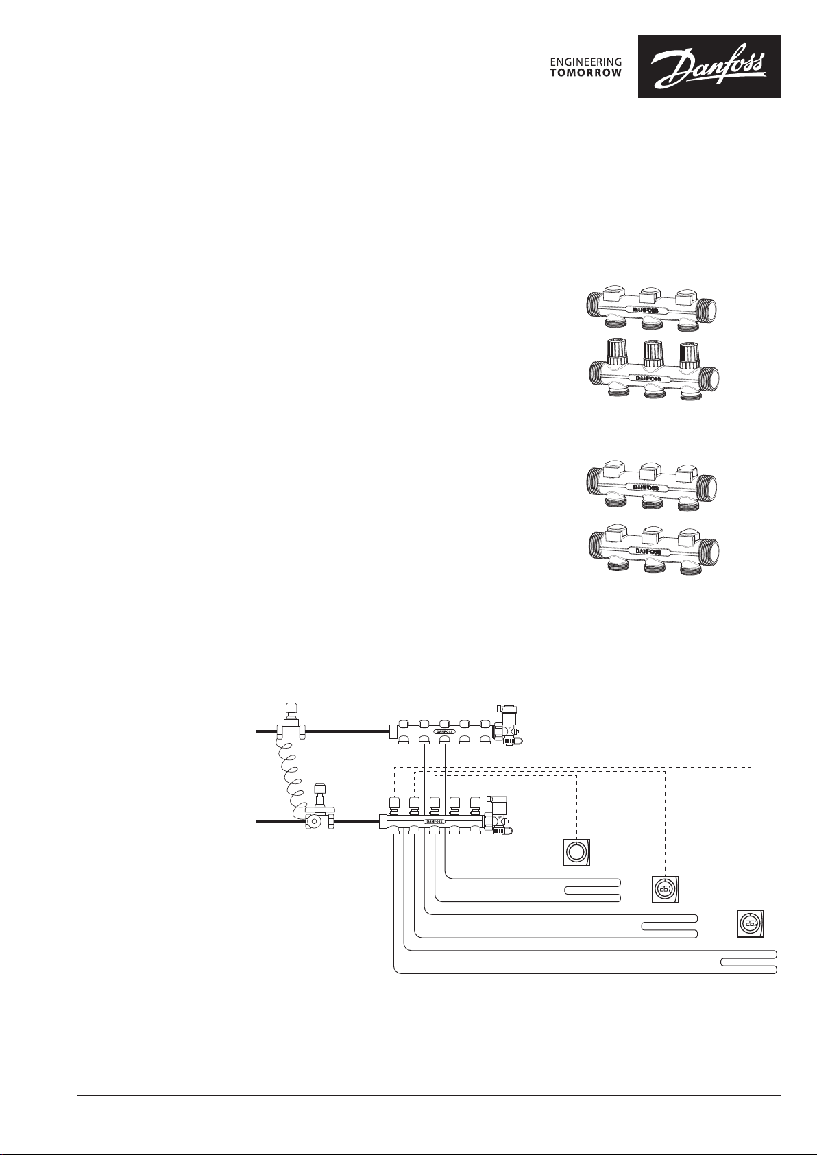
应用
FHR/FHR-B型分集水器应用在地板采暖系统中,
地板采暖系统中的每个回路都分别连接到分集水
器上,实现各个回路热量的单独控制。
分集水器由一个分水器和一个集水器组成。分集
水器支路数为2-8路,配套装置各形式末端尾件。
全系列共分为两款供选择:
FHR型。分水器各支路具有关断功能,集水器各
支路内置预设定流量调节阀,可与热电执行器相
连接,配套恒温控制器实现分室温控。
FHR-B型。分水器与集水器功能一致,各支路具
有关断功能。
FHR 型
FHR-B 型
系统布置
© Danfoss | FEC | 2020.11
AI361466798708zh-CN0101 | 1
参数表 FHR/FHR-B型分集水器
088U0925.BR.01.01
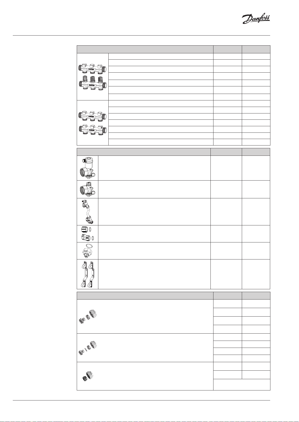
订货
附件
描述 型号 订货编号
分集水器 2+2 FHR 2
分集水器 3+3 FHR 3
分集水器 4+4 FHR 4
分集水器 5+5 FHR 5
分集水器 6+6 FHR 6
分集水器 7+7 FHR 7
分集水器 8+8 FHR 8
分集水器 2+2 FHR-B 2
分集水器 3+3 FHR-B 3
分集水器 4+4 FHR-B 4
分集水器 5+5 FHR-B 5
分集水器 6+6 FHR-B 6
分集水器 7+7 FHR-B 7
分集水器 8+8 FHR-B 8
088U0882
088U0883
088U0884
088U0885
088U0886
088U0887
088U0888
088U0872
088U0873
088U0874
088U0875
088U0876
088U0877
088U0878
描述 型号 订货编号
末端组件1个,含自动排气和泄水阀 FHRRPO-EA
末端组件1个,含手动排气和泄水阀 FHPRO-EM
088U0920
088U0921
连接件
压差旁通尾件1套,含定值压差旁通,自动排气和泄水
阀
混水接头1套 FHPRO-SC
手动排气堵头1个
2个安装支架 FHPRO-MB
FHPRO-ED
FHPRO-
MEEM
088U0922
088U0923
088U0924
088U0925
描述 型号, mm 订货编号
PEX 管连接件,管道应符合ISO15875标准
• 最大工作压力: 6 bar
16 × 2
20 × 2
013G4156
013G4160
• 测试压力: 10 bar
• 最高水温: 95 °C
• G ¾” 内螺纹
ALUPEX 管连接件.
• 最大工作压力: 6 bar
• 测试压力: 10 bar
• 最高水温: 95 °C
• G ¾” 内螺纹
铜管和铜管连接件
• 最大工作压力: 6 bar
• 测试压力: 10 bar
20 × 2.25
20 × 2.5
16 × 2
20 × 2
20 × 2.25
20 × 2.5
16
18
013G4093
013G4161
013G4186
013G4190
013G4093
013G4191
013G4126
013G4128
• 最高水温: 95 °C
• G ¾” 内螺纹
实际运行最高水温不能超过管材制造商要求的水温。
2 | © Danfoss | FEC | 2020.11
AI361466798708zh-CN0101

参数表 FHR/FHR-B型分集水器
Presetting.03.00
Capacity / commissioning
Capacity
The pre-setting of the manifold valves determines the ow in the oor heating tubes and
is therefore an important factor for obtaining
optimal hydraulic balance in the system.
A correct hydraulic balance is important if
optimal comfort shall be achieved with a minimum of energy consumption and is easily
carried out following the example shown
below.
Example
Room 1: 1. Determine longest tube/largest room 25 m
2. Desired cooling (ΔT) 10 °C (typical)
3. Determine heat requirement for the room 150 W/m
4. Conversion factor 1,16
5. Calculation of ow for the room
150 W/m2 × 25 m
Q
=
(l/h)
10 °C × 1,16
2
323
=
l/h
Room 2: 6. Determine area for the next room 15 m2
7. Calculation of ow for the room (ΔT and
heat requirement is assumed identical for
the rooms in this case)
1
1 2 3 4 5 6 7 N
150 W/m2 × 15 m
Q
=
(l/h)
10 °C × 1,16
2
193
=
l/h
0,8
0,6
0,5
0,4
0,3
2
2
Presetting the manifolds
0,2
ΔP
[bar]
0,1
0,08
0,06
0,05
0,04
0,03
0,02
0,01
10 20 30 50 70 100
Q [l/h]
The diagram shows the capacities for each
heating circuit at dierent pre-settings of the
manifold valves.
200 300 500 700 1000 2000
3000
Based on above calculations the and capacity
diagrams each manifold is pre-set by rotating
the red ring until correct value on the ring is
in-line with the sight mark on the valve
© Danfoss | FEC | 2020.11
Presetting.01.00
1. Presetting range
2. Factory setting and one-pipe system
3. Reference mark
Presetting.02.00
AI361466798708zh-CN0101 | 3

参数表 FHR/FHR-B型分集水器
分集水器流量与压降曲线
FHR
预设定 1 2 3 4 5 6 7 N
Kv (m3/h)
0,28 0,34 0,40 0,48 0,57 0,67 0,82 1,00
1
1 2 3 4 5 6 7 N
0,8
0,6
0,5
0,4
0,3
0,2
ΔP
[bar]
0,1
0,08
0,06
0,05
0,04
0,03
0,02
0,01
10 20 30 50 70 100
200 300 500 700 1000
Q [l/h]
FHR-B
调节圈数 0,5 1 1,5 2 2,5 3 3,5 4 4,5
Kv (m3/h)
1
0,16 0,42 0,61 0,79 0,91 0,99 1,20 1,37 1,48
1½
2½ 3½½
1 2 3 4
0,8
0,6
0,5
0,4
0,3
0,2
ΔP
[bar]
0,1
0,08
0,06
0,05
0,04
0,03
0,02
0,01
10 20 30 50 70 100
200 300 500 700 1000 2000
3000
Q [l/h]
运行工况
4 | © Danfoss | FEC | 2020.11
最大压差(带热电执行器) ...............0.6 bar
最大工作压力 . . . . . . . . . . . . . . . . . . . . . . .10 bar
最大测试压力.......................16 bar
最高水温 ...........................90 °C
AI361466798708zh-CN0101

参数表 FHR/FHR-B型分集水器
尺寸
G1” - ISO228/1
G3/4” - ISO228/1
315
211
G1” - ISO228/1
50
G3/4” - ISO228/1
L1
68
86,7
回路 2+2 3+3 4+4 5+5 6+6 7+7 8+8
L1 (mm)
G1” - ISO228/1
164 214 264 314 364 414 464
35
G3/4” - ISO228/1
348
211
G1” - ISO228/1
50
G3/4” - ISO228/1
L1
68
87
回路 2+2 3+3 4+4 5+5 6+6 7+7 8+8
L1 (mm)
174 224 274 324 374 424 474
35
© Danfoss | FEC | 2020.11
AI361466798708zh-CN0101 | 5

Danf
尺寸
G1” - ISO228/1
G1” - ISO228/1
G3/4” - ISO228/1
211
35
294
回路
L1 (mm)
35,5 63
50
G3/4” - ISO228/1
L1
2+2 3+3 4+4 5+5 6+6 7+7 8+8
143 193 243 293 343 393 443
57
37
57
31,535,5
088U0921.d.01.01
088U0920.d.01.01
68
87
37
oss Danfoss
6 | © Danfoss | FEC | 2020.11
Danfoss ઼ᡰᴹ Danfoss Danfoss A/S( )
AI361466798708zh-CN0101
 Loading...