

Page 1
Data Sheet
FHR/FHR-B Floor Heating Manifold
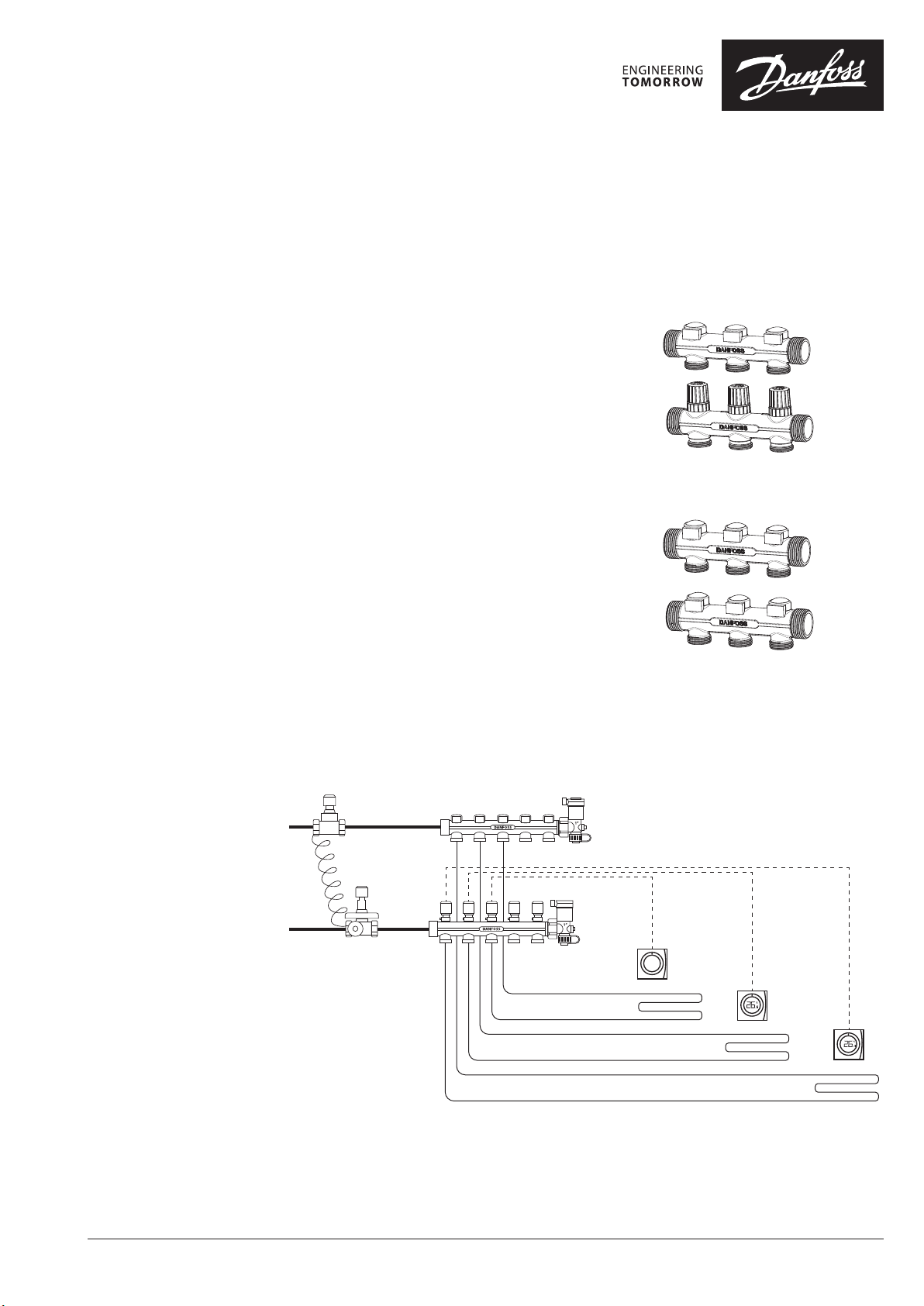
Application
The FHR/FHR-B Manifold is used for controlling
water flow in under floor heating systems. Each
tube of the floor heating system is connected to
the manifold, thus making it possible to control
water flow or heat supply to each in the building
individually.
The manifold consists of a supply and return manifold. The manifold is supplied in modules of 2 to 8
outlets. The end pieces are placed at the end of the
manifold.
Two types in this series are provided:
Typ e FHR. The supply manifold includes possibility
for individual shut-off of each circuit. The return
manifold is equipped with integrated pre-setting
valves securing optimal hydraulic balance in the
system. The valves can be controlled electronically
by thermal actuators with RA connection.
Typ e FHR-B. The supply and return mani fold include
shut off function for each loop.
FHR type
FHR-B type
System Layout
© Danfoss | FEC | 2020.11
AI361466798708en-000101 | 1
Page 2
Data Sheet FHR/FHR-B Floor Heating Manifold
088U0925.BR.01.01
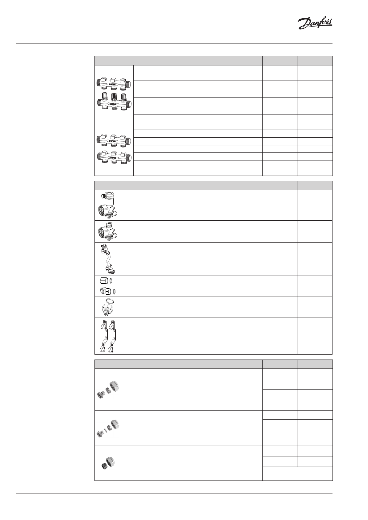
Ordering
Accessories
Description Typ e Code no.
Manifold set 2+2 FHR 2 088U0882
Manifold set 3+3 FHR 3 088U0883
Manifold set 4+4 FHR 4 088U0884
Manifold set 5+5 FHR 5 088U0885
Manifold set 6+6 FHR 6 088U0886
Manifold set 7+7 FHR 7 088U0887
Manifold set 8+8 FHR 8 088U0888
Manifold set 2+2 FHR-B 2 088U0872
Manifold set 3+3 FHR-B 3 088U0873
Manifold set 4+4 FHR-B 4 088U0874
Manifold set 5+5 FHR-B 5 088U0875
Manifold set 6+6 FHR-B 6 088U0876
Manifold set 7+7 FHR-B 7 088U0877
Manifold set 8+8 FHR-B 8 088U0878
Description Typ e Code no.
End section — automatic airvent and purge valve FHRRPO-EA 088U0920
End section — manual airvent and purge valve FHPRO-EM 088U0921
Compression Fittings
By-pass section — automatic air vent, purge valve and
by-pass valve
FHPRO-ED 088U0922
Mixing Shunt connector — one set FHPRO-SC 088U0923
End section — Air vent end without drain FHPRO-MEEM 088U0924
Mounting brackets — set FHPRO-MB 088U0925
Description Type, mm Code no.
Compression fittings for PEX tubing in accordance with
ISO 15875.
• Max working pressure: 6 bar
• Test pressure: 10 bar
• Max. flow temperature: 95 °C
• G ¾” internal thread
Compression fittings for ALUPEX tubing.
• Max working pressure: 6 bar
• Test pressure: 10 bar
• Max. flow temperature: 95 °C
• G ¾” internal thread
Compression fittings for STEEL and COPPER tubing
• Max working pressure: 6 bar
• Test pressure: 10 bar
16 × 2 013G4156
20 × 2 013G4160
20 × 2,25 013G4093
20 × 2,5 013G4161
16 × 2 013G4186
20 × 2 013G4190
20 × 2,25 013G4093
20 × 2,5 013G4191
16 013G4126
18 013G4128
• Max. flow temperature: 95 °C
• G ¾” internal thread
2 | © Danfoss | FEC | 2020.11
Note: Max flow temperature given by the tube manufacturer must not be exceeded.
AI361466798708en-000101
Page 3

Data Sheet FHR/FHR-B Floor Heating Manifold
Presetting.03.00
Capacity / commissioning
Capacity
The pre-setting of the manifold valves determines
the flow in the floor heating tubes and is therefore
an important factor for obtaining optimal hydraulic balance in the system.
A correct hydraulic balance is important if optimal
comfort shall be achieved with a minimum of
energy consumption and is easily carried out following the example shown below.
Example
Room 1: 1. Determine longest tube/largest room 25 m
2. Desired cooling (ΔT) 10 °C (typical)
3. Determine heat requirement for the room 150 W/m
4. Conversion factor 1,16
5. Calculation of flow for the room
Q (l/h) =
150 W/m2 x 25 m
10 °C x 1,16
2
= 323 l/h
Room 2: 6. Determine area for the next room 15 m2
7. Calculation of flow for the room (ΔT and heat
requirement is assumed identical for the rooms
Q (l/h) =
in this case)
1
1 2 3 4 5 6 7 N
150 W/m2 x 15 m
10 °C x 1,16
2
= 193 l/ h
0,8
0,6
0,5
0,4
0,3
2
2
Presetting the manifolds
0,2
∆P
[bar]
0,1
0,08
0,06
0,05
0,04
0,03
0,02
0,01
10 20 30 50 70 100
Q [l/h]
The diagram shows the capacities for each heating
circuit at different pre-settings of the manifold
valves.
200 300 500 700 1000 2000
3000
Based on above calculations the and capacity diagrams each manifold is pre-set by rotating the red
ring until correct value on the ring is in-line with
the sight mark on the valve
© Danfoss | FEC | 2020.11
Presetting.01.00
1. Presetting range
2. Factory setting and one-pipe system
3. Reference mark
Presetting.02.00
AI361466798708en-000101 | 3
Page 4

Data Sheet FHR/FHR-B Floor Heating Manifold
Capacity
FHR
Presetting 1 2 3 4 5 6 7 N
Kv (m3/h) 0,28 0,34 0,40 0,48 0,57 0,67 0,82 1,00
1
1 2 3 4 5 6 7 N
0,8
0,6
0,5
0,4
0,3
0,2
∆P
[bar]
0,1
0,08
0,06
0,05
0,04
0,03
0,02
0,01
10 20 30 50 70 100
200 300 500 700 1000
Q [l/h]
FHR-B
Number of turns 0,5 1 1,5 2 2,5 3 3,5 4 4,5
Kv (m3/h) 0,16 0,42 0,61 0,79 0,91 0,99 1,20 1,37 1,48
1½
2½ 3½½
1
1 2 3 4
0,8
0,6
0,5
0,4
0,3
0,2
∆P
[bar]
0,1
0,08
0,06
0,05
0,04
0,03
0,02
0,01
10 20 30 50 70 100
200 300 500 700 1000 2000
3000
Q [l/h]
Operation Conditions
4 | © Danfoss | FEC | 2020.11
Max. differential pressure .................0,6 bar
Max. working pressure ...................10 bar
Max. test pressure ........................16 bar
Max. flow temperature ...................90 °C
AI361466798708en-000101
Page 5
Data Sheet FHR/FHR-B Floor Heating Manifold
Capacity
G1” - ISO228/1
G3/4” - ISO228/1
315
211
G1” - ISO228/1
50
G3/4” - ISO228/1
L1
68
86,7
Typ e 2+2 3+3 4+4 5+5 6+6 7+7 8+8
L1 (m m) 164 214 264 314 364 414 464
G1” - ISO228/1
35
G3/4” - ISO228/1
348
211
G1” - ISO228/1
50
G3/4” - ISO228/1
L1
68
87
Typ e 2+2 3+3 4+4 5+5 6+6 7+7 8+8
L1 (m m) 174 224 274 324 374 424 474
35
© Danfoss | FEC | 2020.11
AI361466798708en-000101 | 5
Page 6

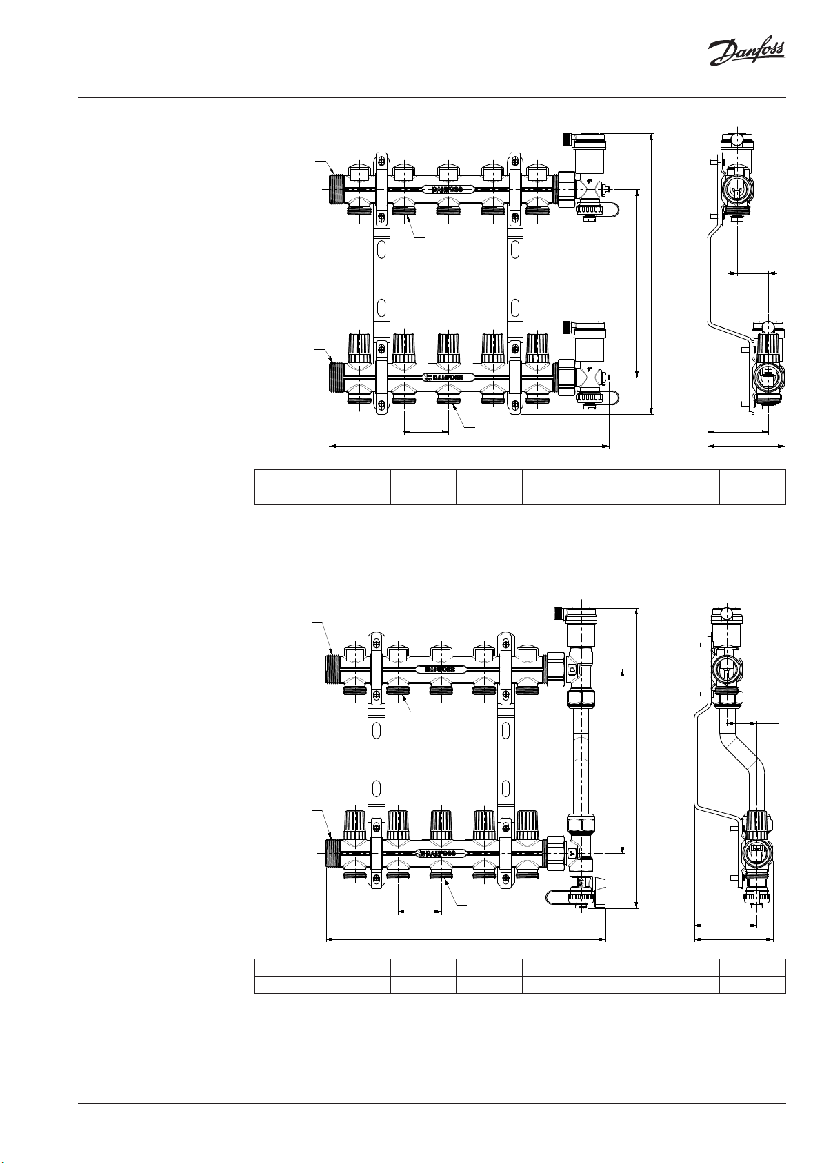
Dimensions
G1” - ISO228/1
G1” - ISO228/1
G3/4” - ISO228/1
211
35
294
50
G3/4” - ISO228/1
L1
68
87
Typ e 2+2 3+3 4+4 5+5 6+6 7+7 8+8
L1 (m m) 143 193 243 293 343 393 443
57
35,5 63
37
57
31,535,5
088U0920.d.01.01
37
088U0921.d.01.01
6 | © Danfoss | FEC | 2020.11
AI361466798708en-000101
 Loading...