

Data Sheet
FH-ME Floor Heating Manifold
Application
The FH-ME Manifold is used for controlling water
ow in under oor heating systems. Each tube of
the oor heating system is connected to the
manifold, thus making it possible to control water
ow or heat supply to each room in the building
individually.
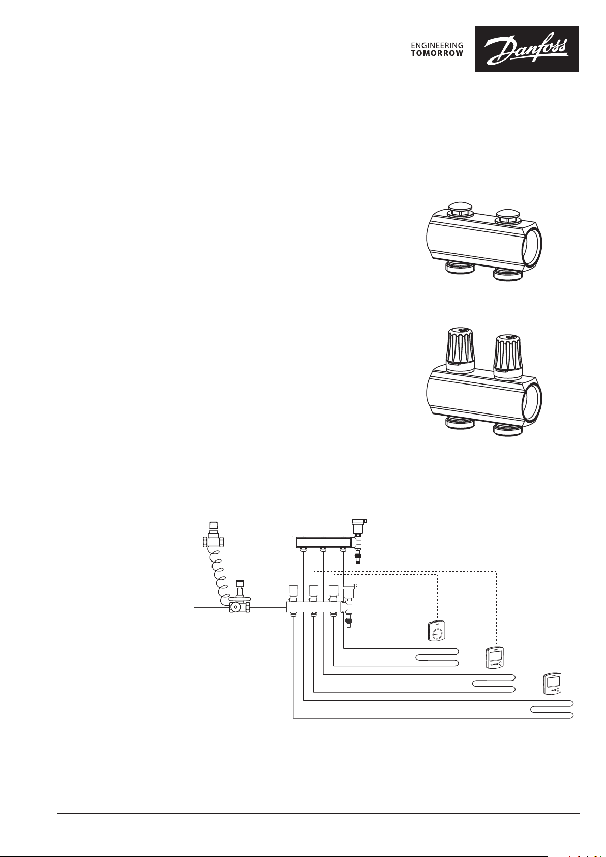
The manifold consists of a supply and return
manifold. The supply manifold includes possibility for individual shut-o of each circuit and as a
ow adjustment. The return manifold is equipped
with integrated Danfoss RA connection.
The valves can be controlled electronically by
thermal actuators or act as self-acting units by
means of remote temperature adjusters.
The manifold is supplied in modules of 2 to 8
outlets. In addition extension pieces are available
for connecting the manifolds in series. Ball valves
are available as an option for positive shut-o
between manifold and system.
The end pieces FHF-EM and FHF-EA are supplied
with manual airvent or alternatively with
automatic airvent, purge and valve. The end
pieces are placed at the end of the manifold.
FH-ME supply
FH-ME return
System Layout
VDUDT402
© Danfoss | FHH | 2015.10 | 1
Data Sheet
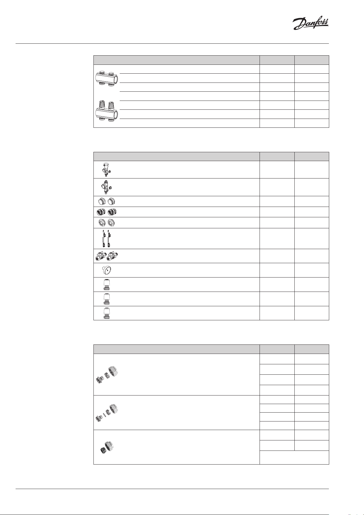
Ordering
Accessories
Description Typ e Code no.
Manifold set 2+2 FH-ME2 088U0612
Manifold set 3+3 FH-ME3 088U0613
Manifold set 4+4 FH-ME4 088U0614
Manifold set 5+5 FH-ME5 088U0615
Manifold set 6+6 FH-ME6 088U0616
Manifold set 7+7 FH-ME7 088U0617
Manifold set 8+8 FH-ME8 088U0618
Description Typ e Code no.
End section - automatic airvent and purge valve FHF-EA 088U0580
End section - manual airvent and purge valve FHF-EM 088U0581
End caps -set FHF-E 088U0582
Connection pieces - set FHF-C 088U0583
Reduction bushes/pieces -set 1" - 3/4" FHF-R 088U0584
Compression Fittings
Mounting brackets - set FHF-MB 088U0585
2 x ball valve 1” with tail piece - for connection to manifold
and for blocking of oor heating system
1 x thermometer 0-60°C Ø35mm - for ow/return temperature measurement
Thermal actuator, 24 V, NC, Danfoss RA connection to valve TWA-A 088H3110
Thermal actuator, 230 V, NC, Danfoss RA connection to
valve
Thermal actuator, 24 V, NC, with end switch, Danfoss RA
connection to valve
Description Type Code no.
Compression ttings for PEX tubing in accordance with ISO
15875.
• Max working pressure: 6 bar
• Test pressure: 10 bar
• Max. ow temperature: 95 °C
• G ¾” internal thread
Compression ttings for ALUPEX tubing.
• Max working pressure: 6 bar
• Test pressure: 10 bar
• Max. ow temperature: 95 °C
• G ¾” internal thread
Compression ttings for STEEL and COPPER tubing
• Max working pressure: 6 bar
• Test pressure: 10 bar
• Max. ow temperature: 95 °C
• G ¾” internal thread
FHF-BV 088U0586
FHF-T 088U0029
TWA-A 088H3112
TWA-A 088H3114
16x2 mm 013G4156
20x2 mm 013G4160
20x2.25 mm 013G4093
20x2.5 mm 013G4161
16x2 mm 013G4186
20x2 mm 013G4190
20x2.25 mm 013G4093
20x2.5 mm 013G4191
16 mm 013G4126
18 mm 013G4128
2 | © Danfoss | FHH | 2015.10
Note: Max ow temperature given by the tube manufacturer must not be exceeded.
VDUDT402

Data Sheet
4
Commissioning
Capacity
The pre-setting of the manifold valves determines the ow in the oor heating tubes and is
therefore an important factor for obtaining
optimal hydraulic balance in the system.
A correct hydraulic balance is important if
optimal comfort shall be achieved with a
minimum of energy consumption and is easily
carried out following the example shown below.
Example
Room 1: 1. Determine longest tube/largest room 25 m
2. Desired cooling (ΔT) 5° C (typical)
3. Determine heat requirement for the room 50 W/m
4. Conversion factor 1.16
5. Calculation of ow for the room
Q (l/h) =
50 W/m2 x 25 m
10° C x 1.16
2
= 108 l/h
Room 2: 6. Determine area for the next room 15 m2
7. Calculation of ow for the room (ΔT and heat
requirement is assumed identical for the rooms
in this case)
Q (l/h) =
50 W/m2 x 15 m
10° C x 1.16
2
= 65 l/h
The diagram shows the capacities of each
heating circuit for dierent settings of the ow
manifold.
The gures ¾ to 4 above the diagram indicate
how many turns of the key are required to obtain
¾ -
the correct water volume (count from closed
position onwards).
2
2
Operation Conditions
VDUDT402
Max. dierential pressure ................0.6 bar
Max. working pressure ...................10 bar
Max. test pressure ........................16 bar
Max. ow temperature ....................90° C
© Danfoss Danfoss | FHH | 2015.10 | 3
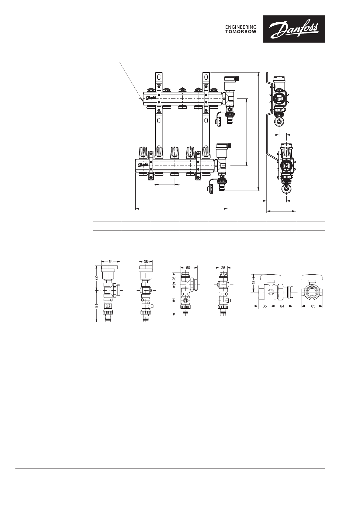
Dimensions
G1" ISO 228/1
23
95
50
376
213
63
L1
Typ e 2+2 3+3 4+4 5+5 6+6 7+7 8+8
L1 (mm) 143 193 243 293 343 393 443
Danfoss A/S
Floor Heating Hydronics • Ulvehavevej 61 • DK-7100 Vejle • Denmark • Phone: +45 7488 8500 • Fax: +45 7488 8501
heating@danfoss.com • www.oorheating.danfoss.com
Danfoss ca n accept no respons ibility for pos sible errors in ca talogues, bro chures and other pr inted material. Da nfoss reserves t he right to alter its p roducts with out notice. This als o applies to produ cts
already o n order provided t hat such alteratio ns can be made with out subsequenti al changes being n ecessary in spe cications alr eady agreed.
All trade marks in this mate rial are proper ty of the respec tive companies . Danfoss and the Dan foss logotyp e are trademark s of Danfoss A/S. Al l rights reserv ed.
4 | © Danfoss | Danfoss | FHH | 2015.10
VDUDT402
 Loading...