

1
2
3
7
6
7
4
5
Installation Guide
FHM-CN Mixing Shunt
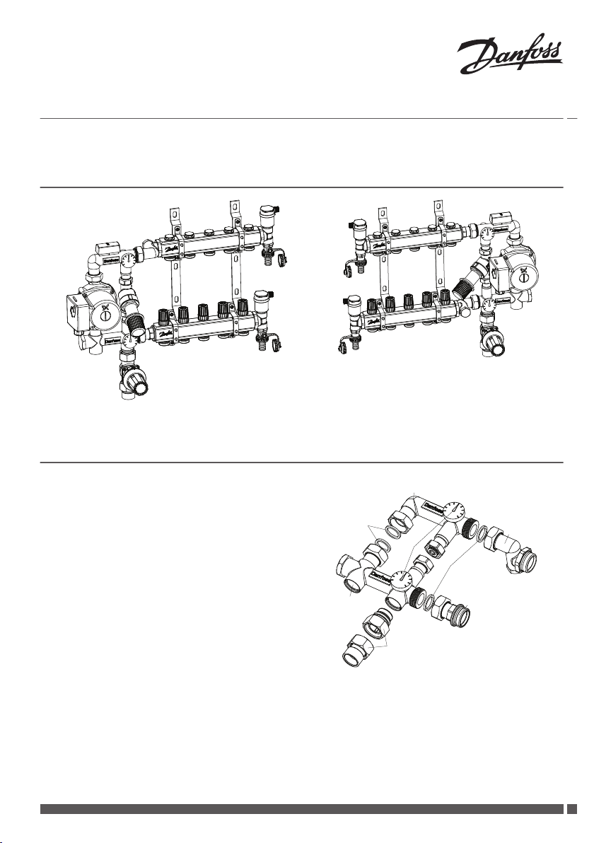
1 Installation Overview
Manifold at right side of mixing shunt Manifold at left side of mixing shunt
2 System Overview
The FHM-CN Mixing Shunt consists of 7 components:
1. Flow parts
2. 2 Thermometers
3. Diplaced connection part to manifold
4. Connection part to manifold
5. RA-C Connection nipple nut, 2 sets RA-C
6. Return parts
7. 4 gaskets
Danfoss Heating Solutions VIIKA102
1
2
3
4
Flow of
secondary side
Return of
secondary side
Return of
primary side
Flow of
primary side
1
2
3
Flow of
secondary side
Return of
secondary side
Return of
primary side
Flow of
primary side
1
4
Installation Guide FHM-CN Mixing Shunt
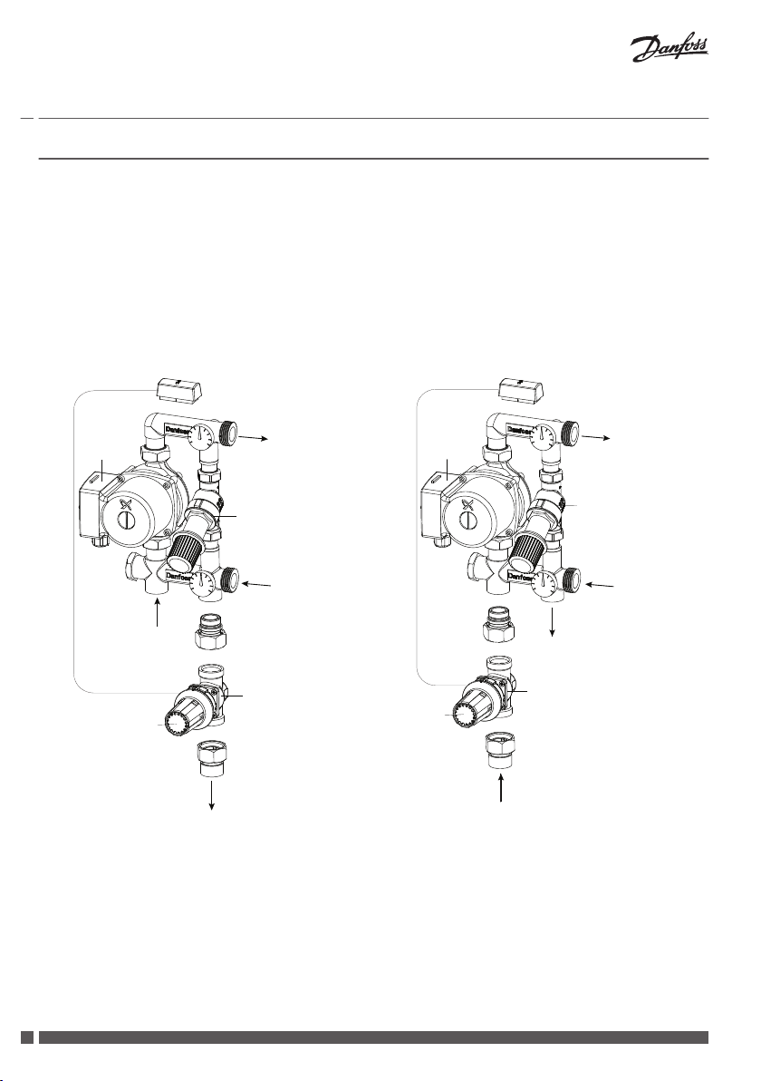
3 Installation Procedure
The FHM-CN with components must be assembled
according to the illustrations.
1. Pump
2. RA-C Valve
3. FTC Floor Heating Sensor
4. Automatic Bypass Control AVDO
Choose installation type dependent on space conditions.
Tightening torque is 30 to 40 Nm.
Note! Identify the arrow on the pump and valve body
AVDO&RA-C, with the flow direction.
Fig. 1: RA-C Return of Primary Side Install
2
Fig. 2: RA-C Flow of Primary Side Install Vertically
VIIKA102 Danfoss Heating Solutions
 Loading...