

Page 1
Data sheet FEV sensors
Control of heating circuit
Products
FEV-IF with integrated sensor FEV-FF with remote sensor
Ordering and
specifications
Application
The FEV is a proportional controller which
opens or closes the heating valve as a function of the temperature deviation.
FEV-FF
To be applied in systems with i.e. fancoils or
induction units. By placing the remote sensor
in the room-air inlet of the unit a smaller reFEV-IF
To be applied in systems with i.e. ceiling-,
floor- or radiator heating. The temperature-
sponse time to temperature changes can be
achieved which will result in a more accurate
temperature control.
adjuster/sensor should be mounted on an
internal wall at a height of approximately 1.5
meter in such a way that the room temperature can be measured accurately.
Type Code no. Sensor Capillary tube Setting range
FEV-IF 013G5467 Integrated sensor 5 m
FEV-FF 013G5466 Remote sensor 2 + 2 m
17-27 °C
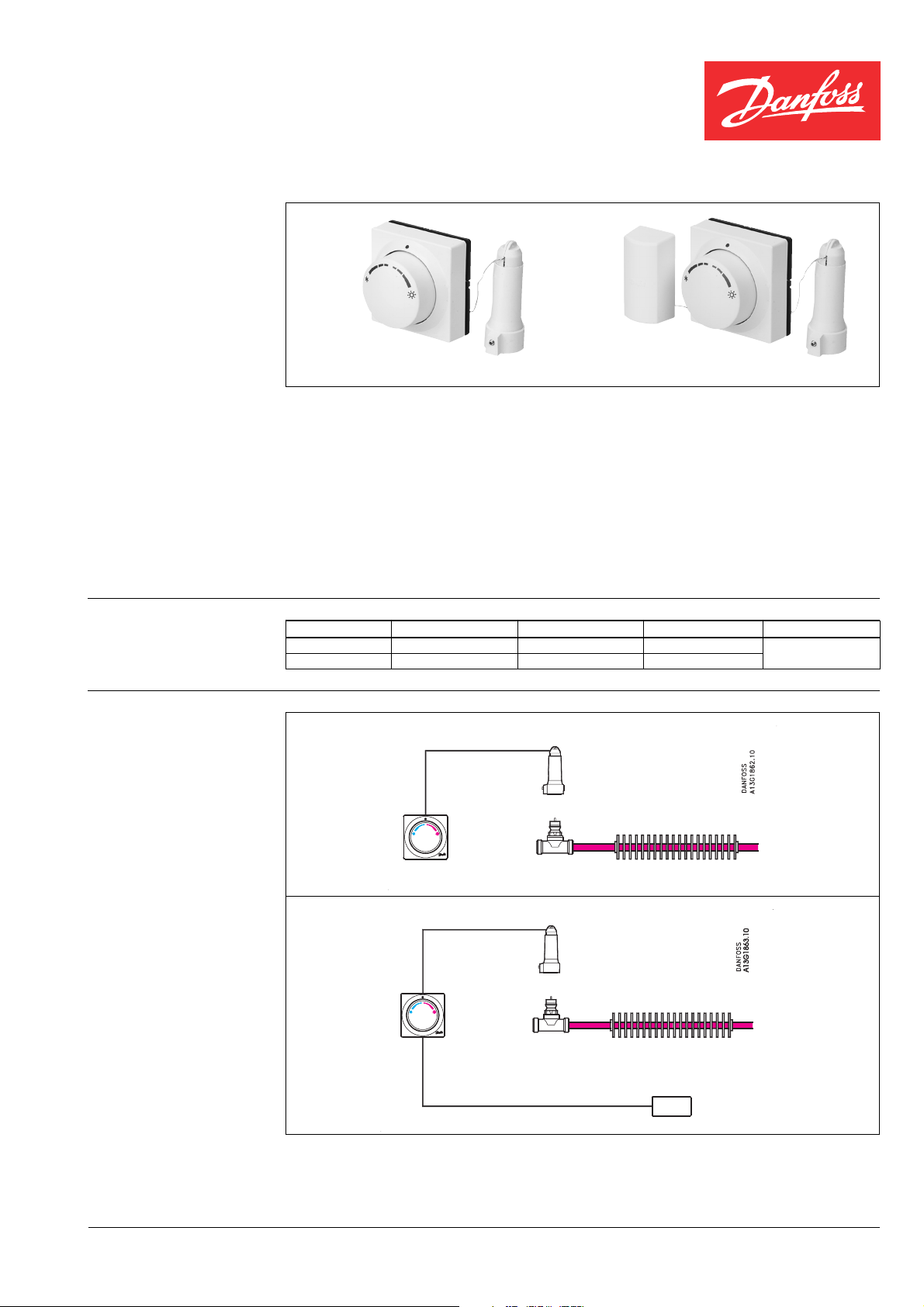
Heating: Floor-, ceiling-, or radiator heating
Heating circuit
FEV-IF
RA-C
RA-N/G
Heating: fancoils/induction units
Heating circuit
FEV-FF
RA-C
RA-N/G
DKCD VD.33.R1.02 © Danfoss 01/2000 1
Page 2
Data sheet FEV sensors
FEV sensor design
Valve adapter
(heating)
Remote temperature adjuster
Remote sensor
(FEV-FF)
Actuator
Temperature setting
FEV sensors can be applied in combination
with RA-N RA-G or RA-C valves. The FEV
sensors are equipped with a direct acting
valve-controller that opens the valve when the
Comfort temperature ~ 22°C at Xp = 0 K(°C)
The FEV sensors have been developed for
heating via water-based systems.
The FEV sensors are based on the self-acting
principle. The liquid-filled sensors control the
valves via capillaries and adapters.
temperature drops below the set temperature.
If the set temperature is equal to or higher
than the room temperature the valve is closed.
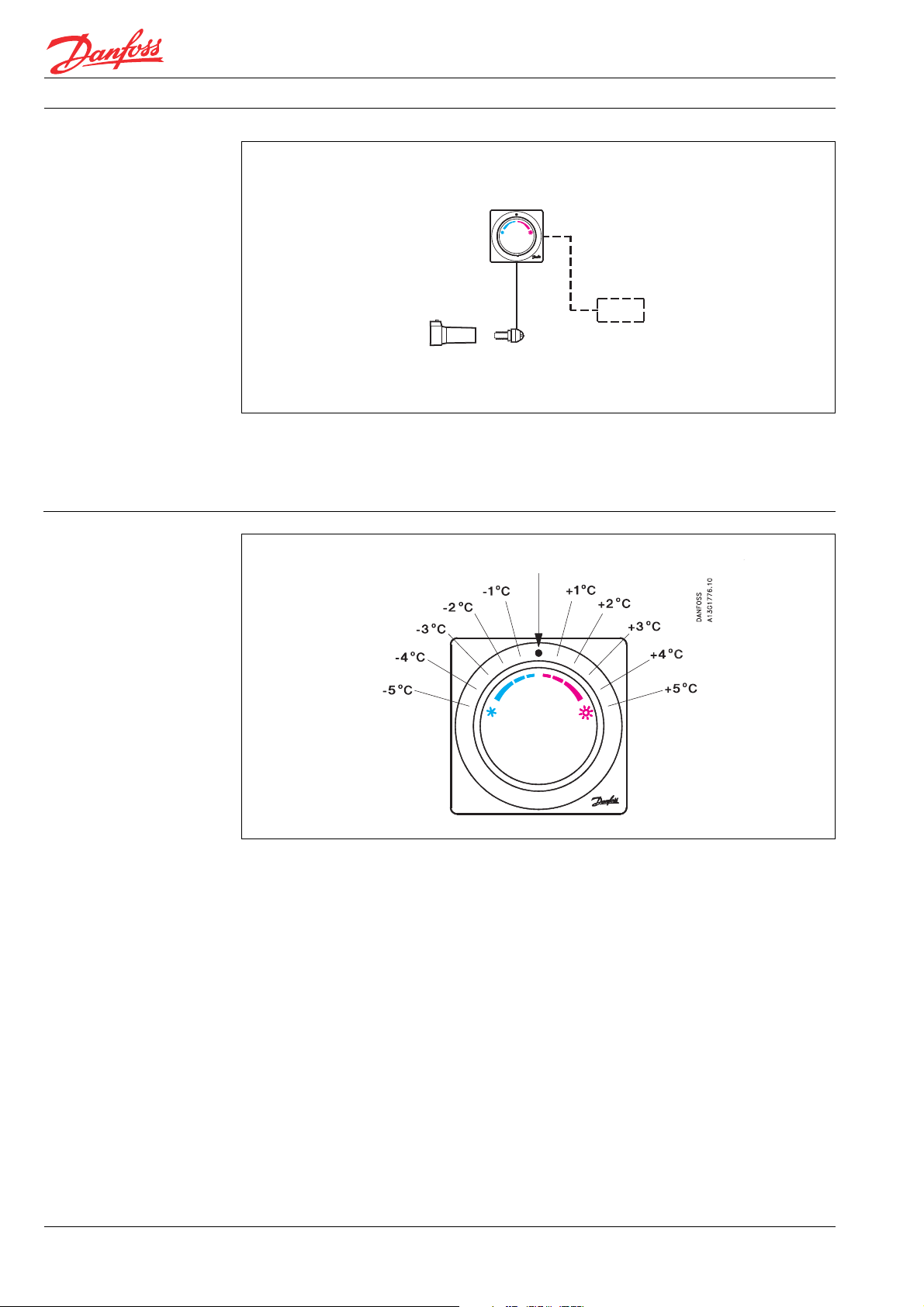
The scale shows the approximate set-point
offset from the comfort temperature which is
approximately 22° C at X
= 0 K.
p
2 VD.33.R1.02 © Danfoss 01/2000 DKCD
Page 3

Data sheet FEV sensors
Temperature control
through heating with FEV
Example
Control area of FEV sensor with RA-N/G and RA-C valve
Xp = 0 K
Xp = 2 K
When the knob has been set in the middle
position the valve will open at temperatures
Heating with FEV thermostat
lower than 22°C. A setting in the red zone
means the valve will open at a higher room
temperature. A setting in the blue zone means
the room temperature will be kept at a value
lower then 22 °C.
Lowering comfort temperature by 4 °C
Waterflow,
heating
Setpoint on knob
Water flow, heating
Limiting the set temperature of FEV sensors
The comfort temperature is lowered by 4°C by
turning the knob to a setting in the blue area.
Because the scale is calibrated at Xp=0 K(°C)
the valve will open when the temperature
drops below 18 °C. In the presetting “N” of the
valve the combination FEV/RA works with a P-
The set temperature of the remote temperature adjuster depends on the sensor type and
the valves, which are used with the sensors.
MIN.
band of approximately 2 K (°C). This means
the valve will be fully open and the flow maxi-
mal when the sensor reaches a temperature
of approx. 16 °C (18°C minus 2 K).
It is easy to limit or lock the set temperature
by means of the built-in locking/limiting de-
vice.
Maximum limitation of temperature areaMinimum limitation of temperature area
MAX.
DKCD VD.33.R1.02 © Danfoss 01/2000 3
Page 4

Data sheet FEV sensors
Design
1. Heating adapter
2. Actuator
3. Adjustment bellows
4. Capillary reel
5. Remote temperature adjuster
6. Bellows
7. Remote temperature sensor
(FEV-FF)
Dimensions
FEV-IF
FEV-FF
VD.33.R1.02 © Danfoss 01/2000 DKCD
 Loading...