

Page 1
1
2 3
Data Sheet
FEK Sensors - Control of Cooling Circuit
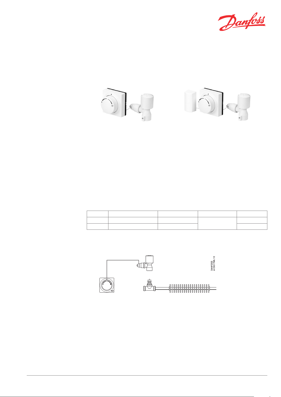
Products
FEK-IF with integrated sensor FEK-FF with remote sensor
Ordering and Specifications
Application
The FEK sensor is installed in rooms which have
surplus heat due to internal or external heat
sources; i.e. only control of cooling circuit is
needed.
When the room temperature rises above the set
temperature the FEK sensor opens the cooling
valve.
FEK-IF as well as FEK-FF sensors can be used for
chilled ceilings, fan-coils and induction units.
Type Sensor Capillary tube Setting range Code no.
FEK-IF Integrated sensor 5 m
FEK-FF Remote sensor 2 + 2 m 013G5464
Control of cooling circuit - chilled ceiling
For cooling circuits in fan-coils and induction
units use the FEK-FF with remote sensor.
The remote sensor can e.g. be placed below the
cabinet of the air inlet or on a separate wall
surface.
By placing the sensor in the air inlet a quicker
reaction time of the air temperature changes is
achieved.
17-27 °C
013G5465
1. FEK-IF
2. RA-C
3. Cooling circuit
Danfoss Heating Solutions VD33S302 © Danfoss 02/2011 1
Page 2

1
2
3
1
2
3
4
Data Sheet FEK Sensors - Control of Cooling Circuit
Control of cooling circuit - fancoils and inductions units
FEK Sensor Design
1. FEK-FF
2. RA-C
3. Cooling circuit
1. Cooling adapter
2. Remote temperature adjuster
3. Actuator
4. Remote sensor (only FEK-FF)
Temperature Setting
The FEK sensors are applied with RA-C valves.
The FEK sensors are equipped with a reverse
device for the control of cooling circuits.
Comfort temperature ~ 22 °C at Xp = 0 K
The FEK sensors have been developed for room
cooling via water-based cooling systems.
With the reverse device the valve in the cooling
circuit will open when the temperature rises
above the set temperature.
The FEK sensors are based on the self-acting
principle. The liquid-filled sensors control the
valves via capillaries and adapters.
2 VD33S302 © Danfoss 02/2011 Danfoss Heating Solutions
Page 3
1
2
1
Data Sheet FEK Sensors - Control of Cooling Circuit
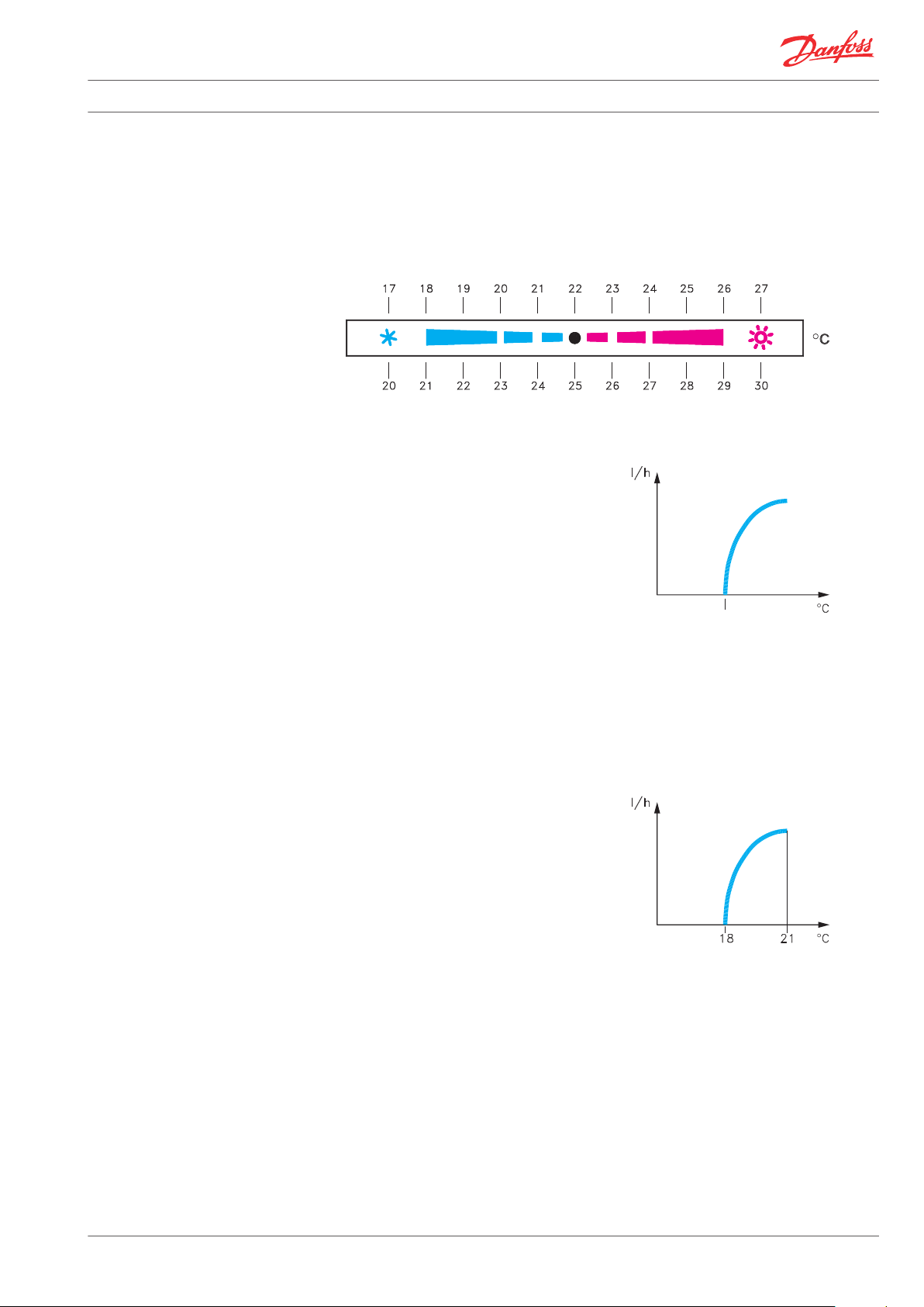
The scale shows the approximate set-point offset
from the comfort temperature which is
approximately 22° C at Xp = 0 K.
Temperature Control
Through Cooling with FEK
Sensor
Control area of FEK sensor with RA-C valve
Xp = 0 K
Xp = 3 K
A setting in the blue temperature area means
that the setpoint of the cooling circuit is placed
below the comfort temperature, i.e. the valve will
open at a lower temperature than the comfort
temperature of appoximately 22 °C.
With a setting in the red temperature area the
setpoint of the cooling circuit is placed above the
comfort temperature. The valve in the cooling
circuit will open at a room temperature above
the comfort temperature of approximately 22 °C.
1. Waterflow cooling
2. Setpoint on knob
Limiting the Set
Temperature of FEK Sensors
Example
The knob is turned to lower the comfort
temperature with 4 °C from 22 °C to approx. 18 °C
at Xp = 0 K.
As the set point temperature is at Xp = 0 K the
valve in the cooling circuit will not open before
the sensor temperature exceeds 18 °C.
In the presetting N the RA-C valve works with a Pband of maximum 3 K. This means that the RA-C
valve will be fully open and give maximum flow
to the cooling circuit at a sensor temperature of
approx. 21 °C (set point: 18 °C + P-band: 3 K).
1. Waterflow, cooling RA-C valve with
presetting N
The set temperature of the remote temperature
adjuster depends on the sensor type and the
valves, which are used with the sensors.
It is easy to limit or lock the set temperature by
means of the built-in locking/limiting device.
Danfoss Heating Solutions VD33S302 © Danfoss 02/2011 3
Page 4

Data Sheet FEK Sensors - Control of Cooling Circuit
Minimum limitation of temperature area Maximum limitation of temperature area
Design
Dimensions
1. Cooling adapter
2. Neutral zone adjustment knob
3. Reverse device
4. Adjustment bellow
5. Actuator
FEK-IF
6. Capillary reel
7. Bellow
8. Remote temperature adjuster
9. Remote temperature sensor (only FEK-FF)
4 VD33S302 © Danfoss 02/2011 Danfoss Heating Solutions
Page 5

Data Sheet FEK Sensors - Control of Cooling Circuit
FEK-FF
Danfoss Heating Solutions VD33S302 © Danfoss 02/2011 5
Page 6

Data Sheet FEK Sensors - Control of Cooling Circuit
6 VD33S302 © Danfoss 02/2011 Danfoss Heating Solutions
Page 7

Data Sheet FEK Sensors - Control of Cooling Circuit
Danfoss Heating Solutions VD33S302 © Danfoss 02/2011 7
Page 8

Data Sheet FEK Sensors - Control of Cooling Circuit
Danfoss A/S
Heating Solutions
Haarupvaenget 11
8600 Silkeborg
Denmark
Phone:+45 7488 8000
Fax: +45 7488 8100
Email: heating.solutions@danfoss.com
www.heating.danfoss.com
Danfoss can accept no responsibility for possible errors in catalogues, brochures and other printed material. Danfoss reserves the right to alter its products without notice. This also applies to products
already on order provided that such alterations can be made without subsequential changes being necessary in specifications already agreed. All trademarks in this material are property of the respective
companies. Danfoss and the Danfoss logotype are trademarks of Danfoss A/S. All rights reserved.
8 VD33S302 © Danfoss 02/2011 Danfoss Heating Solutions
 Loading...