

Page 1
1
2
3
4
5
Data Sheet
FED-W Sensors - Sequence Control of Cooling and
Heating Circuit
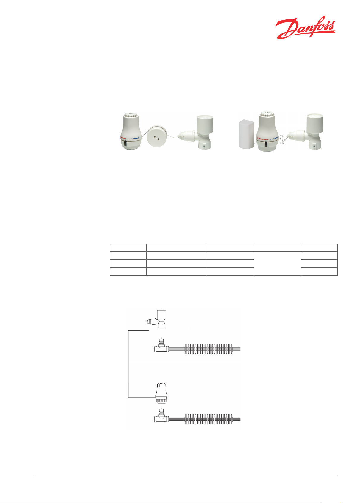
Products
FED-W 10 with integrated sensor FED-WF with remote sensor
Ordering and Specifications
Application
The FED sensors are used in applications in which
a cooling and a heating circuit are to be
controlled by one controller.
Both FED-W and FED-WF sensors can be applied
to chilled ceilings, fancoils or induction units.
Type Sensor Capillary tube Setting range Code no.
FED-W 0.5 Integrated sensor 0.5 m
FED-W 10 Integrated sensor 10 m 013G5480
FED-WF Remote sensor 2 + 2 m 013G54xx
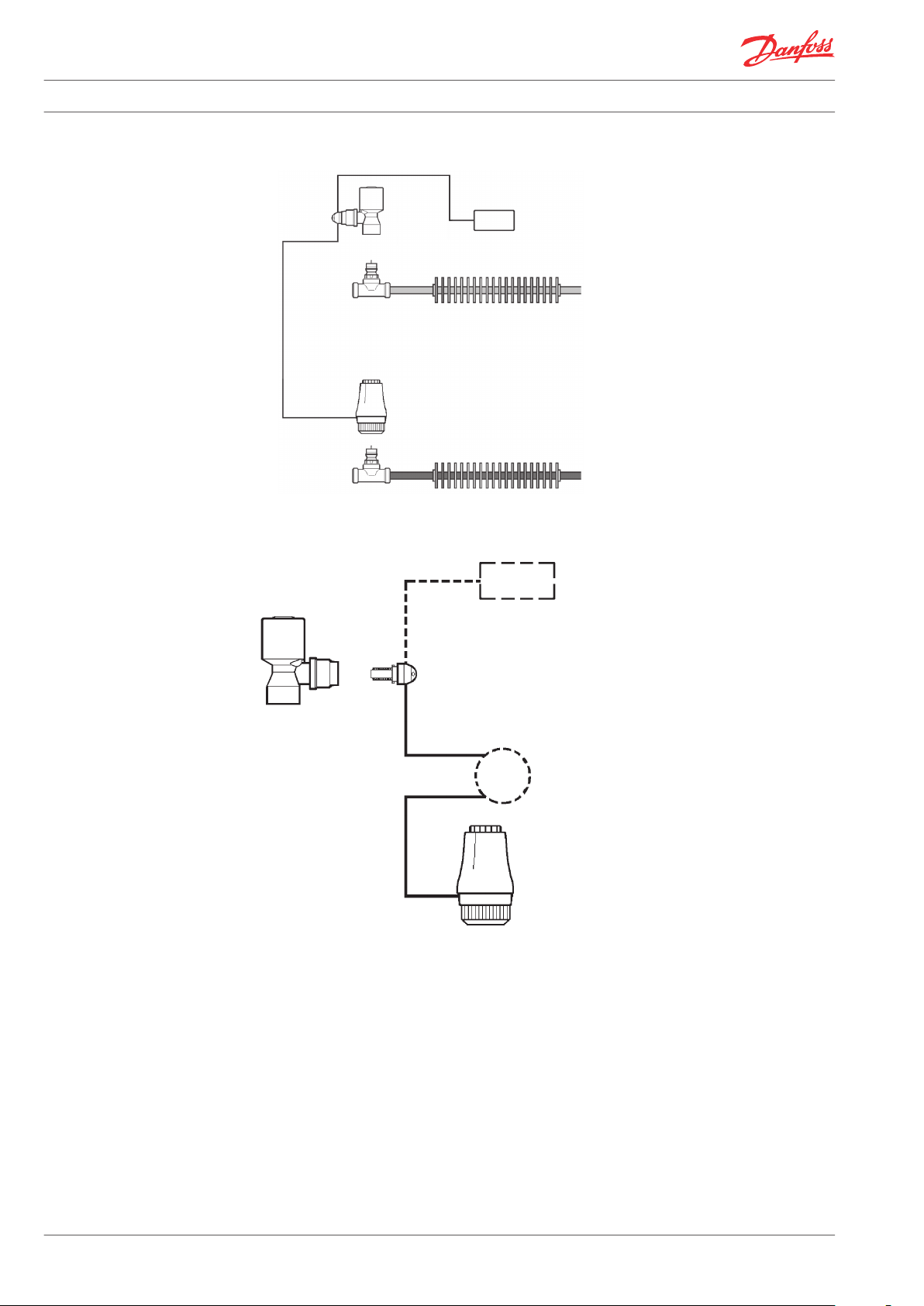
Sequence control of 4-pipe chilled ceiling or radiator
For control of cooling and heating circuits in
fancoil and induction units use the FED-WF with
remote sensor.
By placing the sensor in the air inlet a quicker
reaction time of the air temperature changes is
achieved.
013G5481
17-27 °C
1. RA-C
2. FED-W
3. RA-N
4. Cooling circuit
5. Heating circuit/radiator
Danfoss Heating Solutions VDUND202 © Danfoss 02/2011 1
Page 2
1
3
2
4
5
2
3
4
5
1
Data Sheet FED-W Sensors - Sequence Control of Cooling and Heating Circuit
Sequence control of fancoils and induction units
1. RA-C
2. FED-WF
3. RA-N / RA-N
4. Cooling circuit
5. Heating circuit
FED Sensor Design
1. Cooling adapter
2. Actuator
3. Remote sensor (only FED-WF)
4. Capillary reel (only FED-W 10)
5. FED-W sensor
The FED sensors are applied with the RA-N and
the RA-C valves.
The FED sensors are equipped with a reverse
The valve in the heating circuit will open when
the temperature falls below the setpoint
temperature.
device for the control of cooling circuits. With the
reverse device the valve in the cooling circuit will
open when the temperature rises above the
setpoint temperature.
2 VDUND202 © Danfoss 02/2011 Danfoss Heating Solutions
Page 3
1
2
3
1
2
Data Sheet FED-W Sensors - Sequence Control of Cooling and Heating Circuit
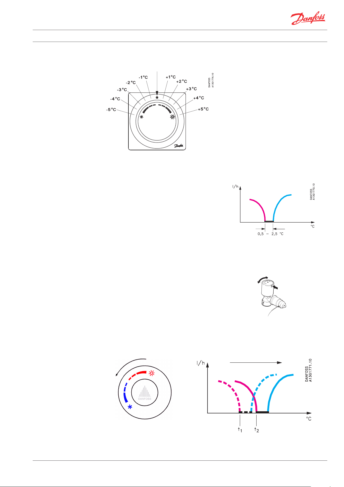
Temperature Setting
Sequence Control
Comfort temperature ~ 22 °C at Xp = 0 K The FED sensors have been developed for room
temperature control via water-based cooling and
heating systems.
The FED sensors are based on the self-acting
principle. The liquid-filled sensors control the
valves via capillaries and adapters.
The scale shows the approximate set-point offset
from the comfort temperature which is
approximately 22° C at Xp = 0 K.
The control is done by the sensor, in which a
Sequence control of cooling and heating circuit
neutral zone is built-in. In the neutral zone both
valves are closed and neither an activation of the
valve in the heating circuit nor of the valve in the
cooling circuit takes place. In that way it is
secured that cooling and heating do not take
place simultaneously.
The neutral zone is in the area from 0.5 - 2.5 °C
dependending on the system design. If the
differential pressure is high on both circuits (~0.6
bar), the neutral zone is at a minimum. On the
other hand if the differential pressure is low on
both circuits (~0.1 bar), the neutral zone is at a
maximum.
An adjustment of the neutral zone can be made
1. Water flow through heating circuit
2. Water flow through cooling circuit
3. Neutral zone
by turning the knob of the cooling adapter with a
pair of pointed pliers. Turning clockwise the
neutral zone is increased, turning counterclockwise the neutral zone is decreased. The
factory setting of the neutral zone is marked in
the knob recess.
Irrespective of the temperature setting of the
FED-sensor the necessary neutral zone will
always be kept. See also figures below.
1. Adjustment of the neutral zone
2. Factory setting mark
Setting of comfort temperature – hotter t1 –> t2 (e.g. 22 °C –> 24 °C)
Danfoss Heating Solutions VDUND202 © Danfoss 02/2011 3
Page 4
*
*
1 2
3
Data Sheet FED-W Sensors - Sequence Control of Cooling and Heating Circuit
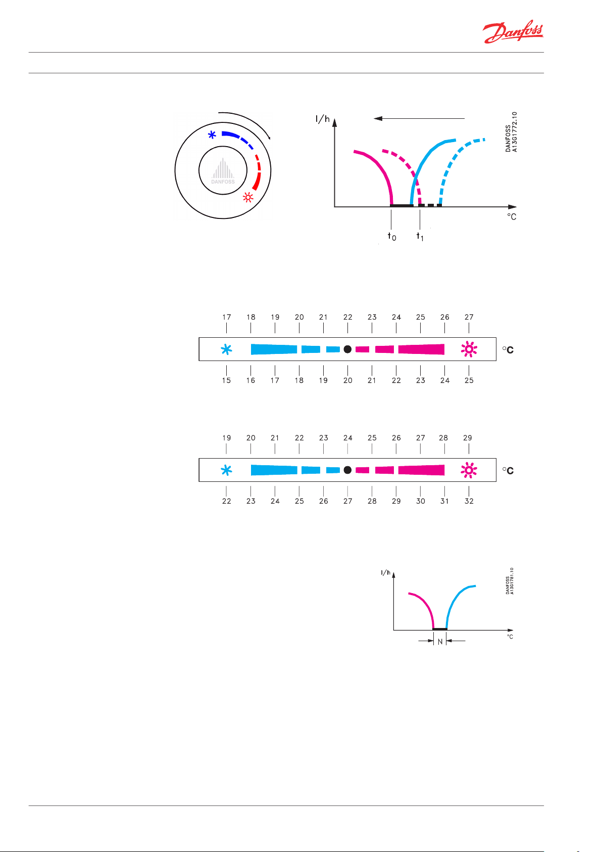
Setting of comfort temperature – colder t1 –> t0 (e.g. 22 °C –> 20 °C)
Temperature Control
Through Sequence Control
with FED Sensor
a) Control area of FEK sensor with RA-C valve
Xp = 0 K
Xp = 2 K
b) Control of cooling circuit - FED with RA-C valve
Xp = 0 K
Xp = 3 K
*Note! Example at neutral zone = 2 °C. Setpoint = 22 °C
The FED sensor controls in sequence via two
temperature scales: one for the heating circuit (a)
and one for the cooling circuit (b).
Sequenzing with FED thermostat
When the setting knob is turned a parallel control
of both temperature scales is taking place. The
neutral zone ensures that cooling and heating do
not take place simultaneously.
A setting in the red temperature area means that
the set point of both cooling and heating circuit
is raised.
A setting in the blue temperature area lowers the
set point of both cooling and heating circuits.
4 VDUND202 © Danfoss 02/2011 Danfoss Heating Solutions
1. Waterflow, heating
2. Waterflow, cooling
3. Setpoint on knob (N = neutral zone)
Page 5
1
2
3
Data Sheet FED-W Sensors - Sequence Control of Cooling and Heating Circuit
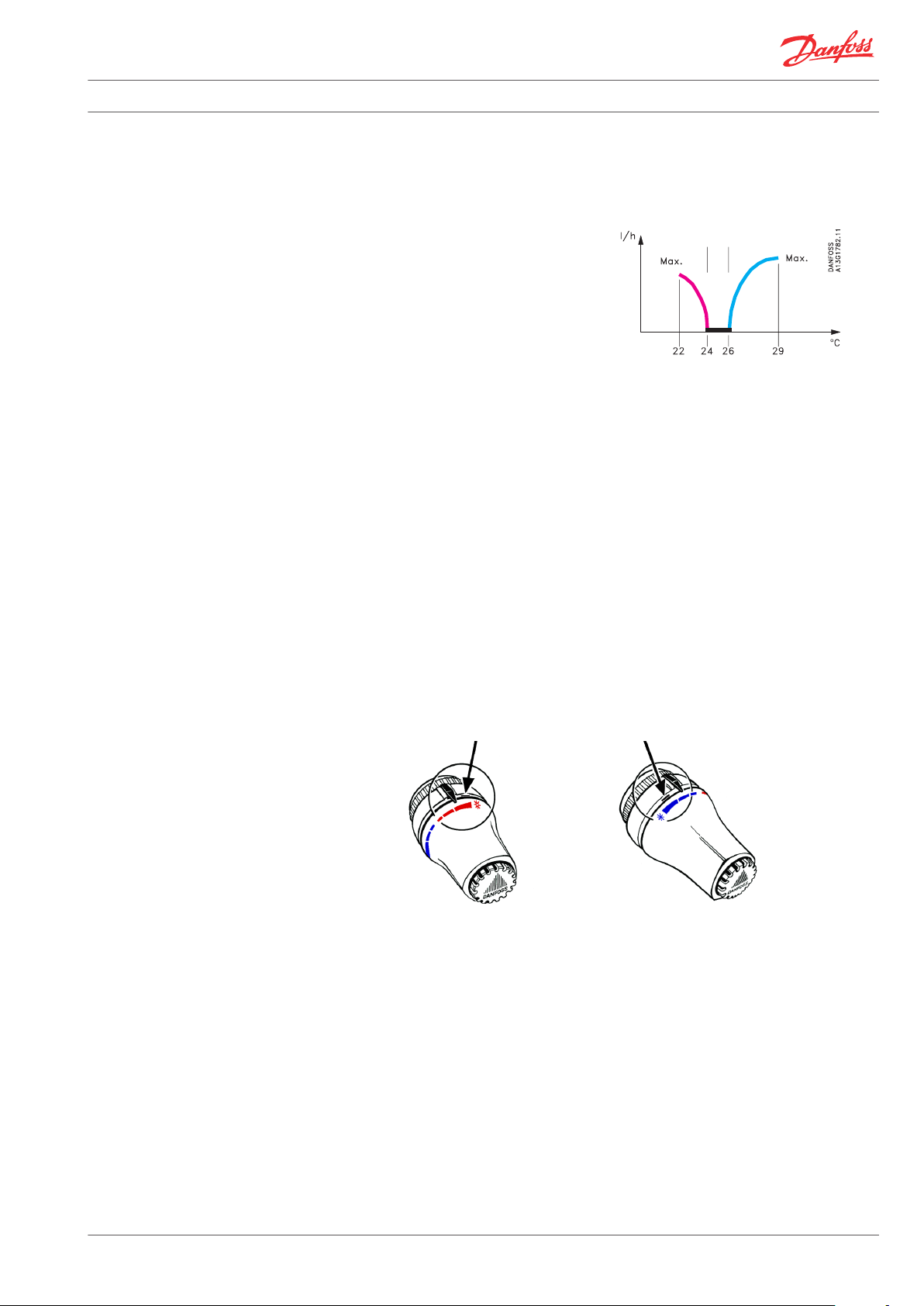
Example
The setting knob is turned to raise the room
temperature with 2 °C from 22 °C to
approximately 24 °C at Xp = 0 K on the heating
valve. Due to the neutral zone the set point of the
cooling valve at Xp = 0 K will be between 0.5-2.5 K
higher depending on the system design.
The valve in the heating circuit will open at a
sensor temperature below 24 °C. If an RA-N valve
is mounted in the heating circuit and
dimensioned at the presetting N, the RA-N valve
will provide full water quantity at a P-band of 2 K,
i.e. a sensor temperature of 22°C.
If the neutral zone e.g. is 2 K the valve in the
cooling circuit will start opening at a sensor
temperature above 26 °C (setpoint: 24 °C +
neutral zone: 2 K).
With a RA-C valve in the cooling circuit
(dimensioned at presetting N) the valve will
provide full water quantity with a P-band of 3 K,
i.e. at a sensor temperature of 29 °C (setpoint: 24
°C + neutral zone: 2 K + P-band: 3 K).
Sequence control when rising the setpoint
temperature with 2 °C
1. Waterflow, heating
2. Waterflow, cooling
3. Neutral zone
Limiting the Set
Temperature of FED Sensors
The set temperature of the remote temperature
adjuster depends on the sensor type and the
valves, which are used with the sensors.
Maximum limitation of temperature area Minimum limitation of temperature area
It is easy to limit or lock the set temperature by
means of the built-in locking/limiting device.
Danfoss Heating Solutions VDUND202 © Danfoss 02/2011 5
Page 6

11
6
5
1010
7
8
9
1
2
3
4
Data Sheet FED-W Sensors - Sequence Control of Cooling and Heating Circuit
Serial Coupling
Several possibilities of placing the FED remote temperature adjuster:
Design
Via the soft but strong ø 0.8 mm capillary and the patented serial coupling of capillary and adapters it
is possible to control two valves in sequence.
1. Heating sensor 7. Reverse device
2. Bellows 8. Adjustment bellow
3. Setting dial 9. Actuator
4. Reset spring 10. Capillary tube
5. Cooling adapter 11. Remote temperature sensor (only FED-WF)
6. Neutral zone adjustment knob
6 VDUND202 © Danfoss 02/2011 Danfoss Heating Solutions
Page 7

Data Sheet FED-W Sensors - Sequence Control of Cooling and Heating Circuit
Dimensions
FED-W
FED-WF
Danfoss Heating Solutions VDUND202 © Danfoss 02/2011 7
Page 8

Data Sheet FED-W Sensors - Sequence Control of Cooling and Heating Circuit
Danfoss A/S
Heating Solutions
Haarupvaenget 11
8600 Silkeborg
Denmark
Phone:+45 7488 8000
Fax: +45 7488 8100
Email: heating.solutions@danfoss.com
www.heating.danfoss.com
Danfoss can accept no responsibility for possible errors in catalogues, brochures and other printed material. Danfoss reserves the right to alter its products without notice. This also applies to products
already on order provided that such alterations can be made without subsequential changes being necessary in specifications already agreed. All trademarks in this material are property of the respective
companies. Danfoss and the Danfoss logotype are trademarks of Danfoss A/S. All rights reserved.
8 VDUND202 © Danfoss 02/2011 Danfoss Heating Solutions
 Loading...