

Page 1
Data sheet FEK sensors
Control of cooling circuit
Products
FEK-IF: with integrated sensor FEK-FF: with remote sensor
Ordering and
specifications
Application
The FEK sensor is installed in rooms which
have surplus heat due to internal or external
heat sources; i.e. only control of cooling circuit
is needed.
When the room temperature rises above the
set temperature the FEK sensor opens the
cooling valve.
FEK-IF as well as FEK-FF sensors can be
For cooling circuits in fancoils and induction
units use the FEK-FF with remote sensor.
The remote sensor can e.g. be placed below
the cabinet of the air inlet or on a separate
wall surface.
By placing the sensor in the air inlet a quicker
reaction time of the air temperature changes
is achieved.
used for chilled ceilings, fancoils and induction units.
Type Code no. Sensor Capillary tube Setting range
FEK-IF 013G5465 Integrated sensor 5 m
FEK-FF 013G5464 Remote sensor 2 + 2 m
17-27 °C
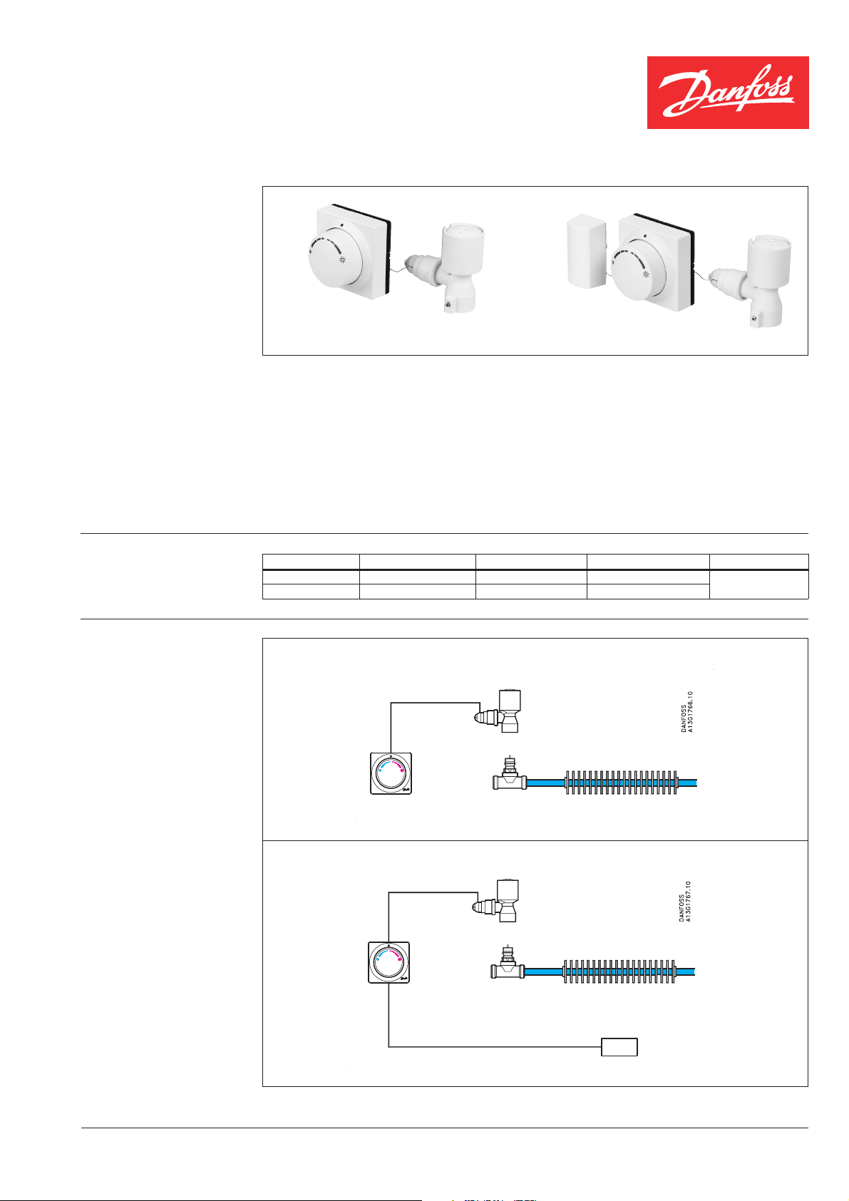
Control of cooling circuit - chilled ceiling
FEK-IF
Cooling circuit
RA-C
Control of cooling circuit - fancoils and inductions units
Cooling circuit
FEK-FF
RA-C
CD-ST VD.33.S1.02. © Danfoss 06/99 1
Page 2
Data sheet Climate controls: FEK sensors
FEK sensor design
Remote temperature adjuster
Temperature setting
Cooling
adapter
Actuator
The FEK sensors are applied with RA-C
valves.
The FEK sensors are equipped with a reverse
Comfort temperature ~ 22 °C at Xp = 0 K
Remote sensor
(only FEK-FF)
device for the control of cooling circuits. With
the reverse device the valve in the cooling
circuit will open when the temperature rises
above the set temperature.
The FEK sensors have been developed for
valves via capillaries and adapters.
room cooling via water-based cooling systems.
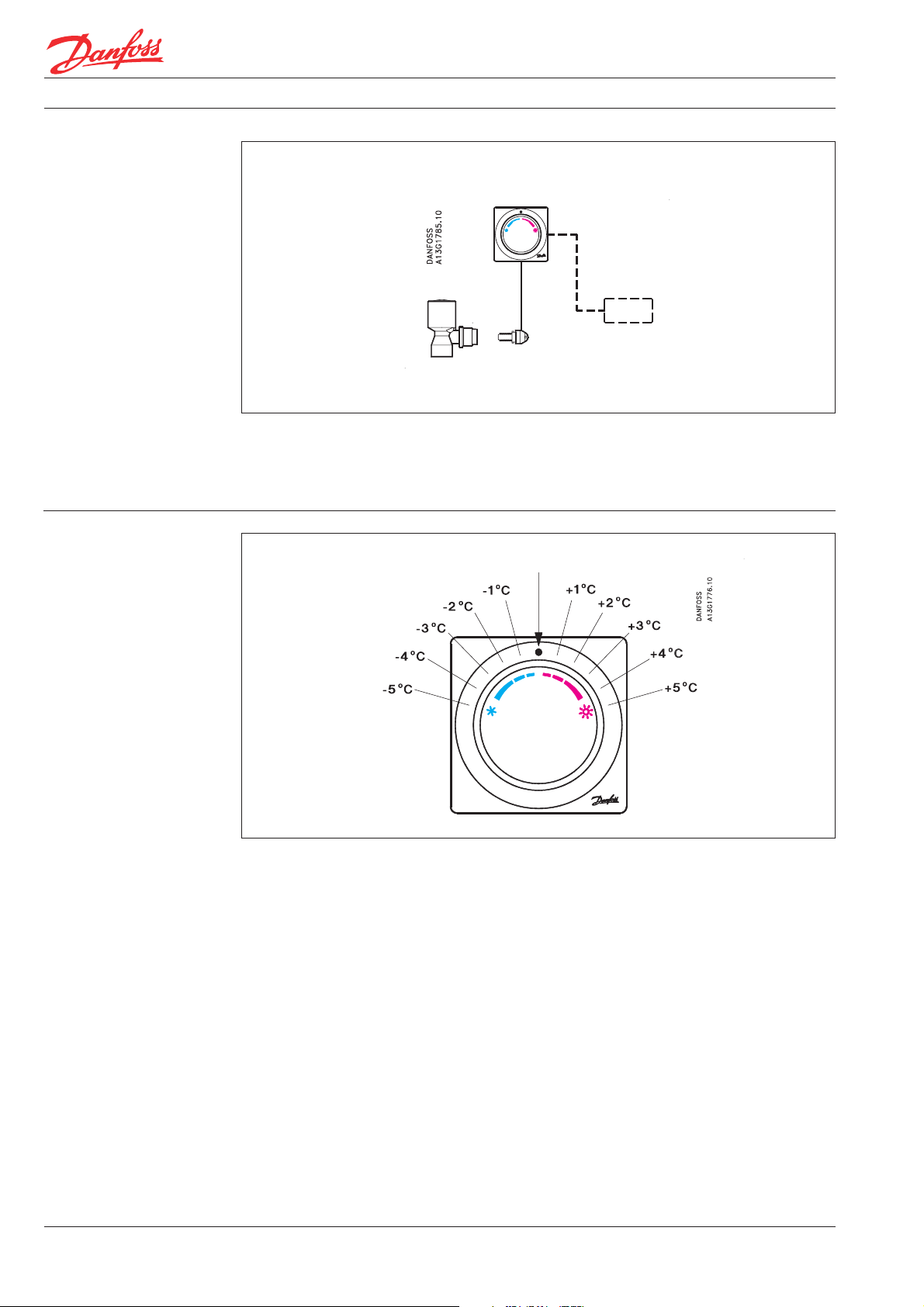
The scale shows the approximate set-point
offset from the comfort temperature which is
The FEK sensors are based on the self-acting
principle. The liquid-filled sensors control the
approximately 22° C at X
= 0 K.
p
2 VD.33.S1.02. © Danfoss 06/99 CD-ST
Page 3

Data sheet Climate controls: FEK sensors
Temperature control
through cooling with FEK
sensor
Example
Control area of FEK sensor with RA-C valve
Xp = 0 K
Xp = 3 K
A setting in the blue temperature area means
that the setpoint of the cooling circuit is placed
below the comfort temperature. I.e. the valve
will open at a lower temperature than the
comfort temperature of appoximately 22 °C.
With a setting in the red temperature area the
setpoint of the cooling circuit is placed above
the comfort temperature. The valve in the
cooling circuit will open at a room temperature
above the comfort temperature of approximately 22 °C.
Lowering comfort temperature with 4 °C.
Cooling with FEK thermostat
Waterflow,
cooling
Setpoint on knob
Waterflow, cooling
RA-C valve with presetting N
Limiting the set temperature of FEK sensors
The knob is turned to lower the comfort temperature with 4 °C from 22 °C to approx.
18° C at X
As the set point temperature is at X
valve in the cooling circuit will not open before
= 0 K.
p
= 0 K the
p
the sensor temperature exceeds 18 °C.
The set temperature of the remote temperature adjuster depends on the sensor type and
the valves, which are used with the sensors.
In the presetting N the RA-C valve works with
a P-band of maximum 3 K. This means that
the RA-C valve will be fully open and give
maximum flow to the cooling circuit at a sensor temperature of approx. 21 °C (set point:
18 °C + P-band: 3 K).
It is easy to limit or lock the set temperature
by means of the built-in locking/limiting device.
Maximum limitation of temperature areaMinimum limitation of temperature area
CD-ST VD.33.S1.02. © Danfoss 06/99 3
Page 4

Data sheet Climate controls: FEK sensors
Design
1. Cooling adapter
2. Neutral zone adjustment
knob
3. Reverse device
4. Adjustment bellow
5. Actuator
6. Capillary reel
7. Bellow
8. Remote temperature
adjuster
9. Remote temperature sensor
(only FEK-FF)
Dimensions
FEK-IF
FEK-FF
VD.33.S1.02. © Danfoss 06/99 CD-ST
 Loading...