


FCM 300 Series
MG.03.B6.2G - VL T is a register ed Danfoss trademark
Table of Contents
Chapter 1 SafetyChapter 1 Safety
Chapter 1 SafetyChapter 1 Safety
Chapter 1 Safety
....................................................................................................................................................................
....................................................................................................................................................................
..................................................................................page 1-1
■ Warnings............................................... page 1-2
■ Safety Precautions ................................ page 1-3
■ Warning Against Unintended Start ....... page 1-3
Chapter 2Chapter 2
Chapter 2Chapter 2
Chapter 2
General TGeneral T
General TGeneral T
General T
echnical Dataechnical Data
echnical Dataechnical Data
echnical Data
........................................................................................................
........................................................................................................
....................................................page 2-1
■ Specifications ........................................ page 2-2
■ General Technical Data ......................... page 2-2
Chapter 3Chapter 3
Chapter 3Chapter 3
Chapter 3
DimensionsDimensions
DimensionsDimensions
Dimensions
..............................................................................................................................................
..............................................................................................................................................
.......................................................................page 3-1
■ Product Dimensions.............................. page 3-2
Chapter 4Chapter 4
Chapter 4Chapter 4
Chapter 4
OrderingOrdering
OrderingOrdering
Ordering
....................................................................................................................................................................
....................................................................................................................................................................
.................................................................................. page 4-1
■ Ordering information ..............................page 4-2
■ Ordering form ........................................ page 4-7
Chapter 5Chapter 5
Chapter 5Chapter 5
Chapter 5
Product ConceptProduct Concept
Product ConceptProduct Concept
Product Concept
............................................................................................................................
............................................................................................................................
..............................................................page 5-1
■ Integrating an AFD and motor .............. page 5-2
Chapter 6Chapter 6
Chapter 6Chapter 6
Chapter 6
InstallationInstallation
InstallationInstallation
Installation
..................................................................................................................................................
..................................................................................................................................................
.........................................................................page 6-1
■ Mechanical installation .......................... page 6-2
■ Motor information..................................page 6-4
■ Terminal Scpecifications ........................ page 6-6
■ Electrical Installation .............................. page 6-8
Chapter 7Chapter 7
Chapter 7Chapter 7
Chapter 7
OperationOperation
OperationOperation
Operation
....................................................................................................................................................
....................................................................................................................................................
..........................................................................page 7-1
■ Start-up ................................................. page 7-2
■ Control Options .....................................page 7-2
■ Local Control Panel ...............................page 7-5
Chapter 8Chapter 8
Chapter 8Chapter 8
Chapter 8
Parameter Group 0: Operation & DisplayParameter Group 0: Operation & Display
Parameter Group 0: Operation & DisplayParameter Group 0: Operation & Display
Parameter Group 0: Operation & Display
..............................................................
..............................................................
............................... page 8-1
■ Parameters 001-019 ............................. page 8-2
Chapter 9Chapter 9
Chapter 9Chapter 9
Chapter 9
Parameter Group 1: Load & MotorParameter Group 1: Load & Motor
Parameter Group 1: Load & MotorParameter Group 1: Load & Motor
Parameter Group 1: Load & Motor
....................................................................
....................................................................
.................................. page 9-1
Instruction Manual
MG.03.B6.22 Document Version 2.0
Software version 2.1x
The software version number
is displayed in parameter 624

FCM 300 Series
MG.03.B6.2G - VLT is a r egistered Danfoss trademark
■ Parameters 100-139 ............................. page 9-2
Chapter 10Chapter 10
Chapter 10Chapter 10
Chapter 10
Parameter Group 2: References & LimitsParameter Group 2: References & Limits
Parameter Group 2: References & LimitsParameter Group 2: References & Limits
Parameter Group 2: References & Limits
..............................................................
..............................................................
...............................
page 10-1
■ Parameters 200-231 ............................. page 10-2
Chapter 11Chapter 11
Chapter 11Chapter 11
Chapter 11
Parameter Group 3: Inputs & OutputsParameter Group 3: Inputs & Outputs
Parameter Group 3: Inputs & OutputsParameter Group 3: Inputs & Outputs
Parameter Group 3: Inputs & Outputs
............................................................
............................................................
..............................page 11-1
■ Parameters 317-340 ............................. page 11-2
Chapter 12Chapter 12
Chapter 12Chapter 12
Chapter 12
Parameter Group 4: Special FunctionsParameter Group 4: Special Functions
Parameter Group 4: Special FunctionsParameter Group 4: Special Functions
Parameter Group 4: Special Functions
........................................................
........................................................
............................page 12-1
■ Parameters 400-446 ............................. page 12-2
Chapter 13Chapter 13
Chapter 13Chapter 13
Chapter 13
Parameter Group 5: Serial CommunicationParameter Group 5: Serial Communication
Parameter Group 5: Serial CommunicationParameter Group 5: Serial Communication
Parameter Group 5: Serial Communication
............................................................
............................................................
..............................page 13-1
■ Parameters 500-543 ............................. page 13-2
Chapter 14Chapter 14
Chapter 14Chapter 14
Chapter 14
Parameter GrParameter Gr
Parameter GrParameter Gr
Parameter Gr
oup 6: Toup 6: T
oup 6: Toup 6: T
oup 6: T
echnical Functionsechnical Functions
echnical Functionsechnical Functions
echnical Functions
..............................................................
..............................................................
...............................page 14-1
■ Parameters 600-635 ............................. page 14-2
Chapter 15Chapter 15
Chapter 15Chapter 15
Chapter 15
Serial CommunicationSerial Communication
Serial CommunicationSerial Communication
Serial Communication
............................................................................................................
............................................................................................................
......................................................page 15-1
■ Danfoss PC Software ............................ page 15-2
■ Serial bus ..............................................page 15-3
■ Telegram Communication ..................... page 15-3
■ Telegram Build-up ................................. page 15-3
■ Data Bytes ............................................ page 15-4
Chapter 16Chapter 16
Chapter 16Chapter 16
Chapter 16
MessagesMessages
MessagesMessages
Messages
..................................................................................................................................................
..................................................................................................................................................
.........................................................................page 16-1
■ List of Warnings and Alarms ................. page 16-2
■ What if the Motor Does Not Start? .......page 16-2
■ Warnings............................................... page 16-3
■ Warnings Words 1+2 and Alarm Word . page 16-5
Chapter 17Chapter 17
Chapter 17Chapter 17
Chapter 17
CE / EMCCE / EMC
CE / EMCCE / EMC
CE / EMC
..................................................................................................................................................
..................................................................................................................................................
.........................................................................page 17-1
Table of Contents

FCM 300 Series
MG.03.B6.2G - VL T is a register ed Danfoss trademark
■ CE Labeling ........................................... page 17-2
■ The Machinery Directive (89/392/EEC) . page 17-2
■ The Low-Voltage Directive /73/23/EEC)page 17-2
■ The EMC Directive (89/336/EEC) ......... page 17-2
■ Compliance with EMC Directive (89/336/EEC) page 17-2
■ What is Covered? ................................. page 17-2
■ Danfoss VLT
®
DriveMotor & CE Labeling page 17-3
■ Galvanic Isolation (PELV ) ...................... page 17-3
■ Ground Leakage Current .....................page 17-4
■ Acoustic Noise ...................................... page 17-4
■ Balance................................................. page 17-4
■ Extreme Running Conditions ................page 17-4
■ EMC Standards .................................... page 17-5
■ Harsh Environments .............................. page 17-6
Chapter 18Chapter 18
Chapter 18Chapter 18
Chapter 18
Special ConditionsSpecial Conditions
Special ConditionsSpecial Conditions
Special Conditions
....................................................................................................................
....................................................................................................................
..........................................................page 18-1
■ Derating ................................................ page 18-2
■ Derating for Ambient Temperature and
for running at low speed ....................... page 18-2
■ Derating for Air Pressure.......................page 18-2
■ Derating for High Switching Frequency .page 18-3
■ Vibration and Shock ............................... page 18-3
■ Air Humidity ...........................................page 18-3
■ Efficiency............................................... page 18-3
■ Harmonics............................................. page 18-4
■ Power Factor ........................................ page 18-4
Chapter 19Chapter 19
Chapter 19Chapter 19
Chapter 19
ParametersParameters
ParametersParameters
Parameters
..............................................................................................................................................
..............................................................................................................................................
.......................................................................page 19-1
■ Factory Parameter Settings .................. page 19-2
Chapter 20Chapter 20
Chapter 20Chapter 20
Chapter 20
IndexIndex
IndexIndex
Index
..............................................................................................................................................................
..............................................................................................................................................................
............................................................................... ..page 20-1
■ Index ..................................................... page 20-2
Table of Contents


FCM 300 Series
MG.03.B6.2G - VL T is a register ed Danfoss trademark
Chapter 1Chapter 1
Chapter 1Chapter 1
Chapter 1 ■ Warnings............................................... page 1-2
■ Safety Precautions ................................ page 1-3
■ Warning Against Unintended Start ....... page 1-3
Safety
1-1
FCM 300 Series
MG.03.B6.2G - VLT is a r egistered Danfoss trademark
Safety
WARNINGWARNING
WARNINGWARNING
WARNING
WARNINGWARNING
WARNINGWARNING
WARNING
CAUTIONCAUTION
CAUTIONCAUTION
CAUTION
The FCM 300 Series unit contains dangerous voltages when connected to line voltage.
After disconnection from the line, wait at least 4 minutes before touching any electrical
components. Also make sure that other voltage inputs have been disconnected. Only a
competent electrician should carry out the electrical installation. Improper installation of
the FCM 300 Series unit may cause equipment failure, serious injury or death. Follow this
manual and the National Electrical Codes (NEC
®
) and local safety codes.
Electrostatic Precaution: Electrostatic discharge (ESD). Many electronic components are
sensitive to static electricity. Voltages so low that they can not be felt, seen or heard, can
reduce the life, affect performance, or completely destroy sensitive electronic.
When performing service, proper ESD equipment should be used to prevent possible
damage from occurring.
It is the reponsibility of the user or the person installing the FCM 300 to provide proper
grounding and branch circuit protection according to the National Electrical Code (NEC
®
)
and local codes.
Motor overload protection is internal to the unit.
1-2

FCM 300 Series
MG.03.B6.2G - VL T is a register ed Danfoss trademark
Safety
Safety Precautions
1. The FCM 300 unit must be disconnected from
the AC line if repair work is to be carried out.
After the AC supply has been disconnected, be
sure the necessary time (4 min.) has passed
before removing line terminal wires.
2. The "Stop/Reset" key on the optional local
control pad or local operating panel of the FCM
300 unit DOES NOT disconnect the equipment
from the AC line and is
NOT to be used as a
safety switch.
3. The installer must supply correct protective
grounding of the equipment and the user must
be protected against supply voltage in
accordance with the National Electrical Code
and local codes. Class 20 motor overload protection is provided internally.
4. The ground leakage currents are higher than 3.5
mA.
5. Use lifting points, if provided. Lift FCM 300 units
vertically only. Lifting points are provided to
support the weight of the FCM 300 only - do not
use lifting points when additional equipment is
attached.
6. Before installation, check unit for fan cover
damage, foot/mounting damage, shaft damage
and loose fasteners. Check nameplate data on
motor.
7. FCM 300 types 311-375 (over 44 lb/20 kg)
should be positioned by lifting machines only for your safety, do not attempt hand lifting. Refer
to "Handling the FCM 300" on page 6-5 for
actual weights.
8. Installation must be correctly fused and isolated
per CE directives.
Warning Against Unintended Start
1. The unit can be brought to a stop by means of
digital commands, bus commands, references or
a local stop, while the FCM 300 unit is
connected to the AC line.
These stop functions are
NOT sufficient to
ensure that no unintended start occurs and
should
NOT be used for personal safety
considerations.
2. While parameters are being changed, the motor
may start.
3. A FCM 300 unit that has been stopped may start
if faults occur int the electronics of the unit, or if a
temporary overload occurs or if there is an
interruption in the AC line supply.
1-3

FCM 300 Series
MG.03.B6.2G - VLT is a r egistered Danfoss trademark

FCM 300 Series
MG.03.B6.2G - VL T is a register ed Danfoss trademark
Chapter 2Chapter 2
Chapter 2Chapter 2
Chapter 2 ■ Specifications ........................................page 2-2
■ General Technical Data ......................... page 2-2
General Technical Data
2-1

FCM 300 Series
MG.03.B6.2G - VLT is a r egistered Danfoss trademark
General Technical Data
■ FCM 305-375 for 3 phases, 380-480 V
FCMFCM
FCMFCM
FCM
305305
305305
305
307307
307307
307
311311
311311
311
315 315
315 315
315
322322
322322
322
330330
330330
330
340340
340340
340
355355
355355
355
375375
375375
375
Motor output
[HP] 0.75 1.0 1.5 2.0 3.0 4.0 5.0 7.5 10.0
[kW] 0.55 0.75 1.1 1.5 2.2 3.0 4.0 5.5 7.5
Motor torque
2 pole [Nm] 1.8 2.4 3.5 4.8 7.0 9.5 12.6 17.5 24.0
4 pole [Nm] 3.5 4.8 7.0 9.6 14.0 19.1 25.4 35.0 48.0
Frame
size [mm] 56 56 143 145 182 182 184 213 215
Weight [kg] 11 13 17 20 26 28 37 56 61
Input current
380 V
2 p 1.4 1.6 2.2 2.8 4.1 5.3 7.0 9.3 13.0
4p 1.4 1.7 2.5 3.3 4.7 6.4 7.9 11.1 15.3
480 V
2 p 1.2 1.3 1.8 2.3 3.3 4.2 5.6 7.4 10.2
4 p 1.1 1.4 2.0 2.6 3.7 5.1 6.4 8.8 11.9
Power
terminals
[AWG] 10 10 10 10 10 10 10 6 6
[mm2] 44444441010
Gland sizes 3XPG16* 3XPG16* 3XPG16* 3XPG16* 3XPG16* 3XPG16* 3XPG16* 1XPG21/ 1XPG21/
3XPG16* 3XPG16*
Max. prefuse
UL
1)
[A] 10 10 10 10 10 15 15 25 25
IEC1) [A] 25 25 25 25 25 25 25 25 25
* PG to NPT adapters can be ordered separately. See page 4-5.
1)
Type gG prefuses must be used. If you wish to observe UL/cUL, KTS-R 500 V pre-fuses or equivalent must
be used. The fuses must provide protection in a circuit capable of supplying max. 100,000 amps rms
(symmetrical), 500 V maximum.
AC line supply, TT, TN and IT* (L1, L2, L3):
- Supply voltage 380-480 V units ......................................................... 3 x 380/400/415/440/460/480 V ±10%
- Supply frequency ...............................................................................................................................50/60 Hz
- Max. imbalance of supply voltage....................................................................... ±2% of rated supply voltage
- Power factor / cos ϕ ....................................................................................................... max. 0.9/1.0 at rated load
- Switching on supply input L1, L2, L3 ............................................................................. approx. 1 time/2 min
See chapter 18, "Special conditions".
*) Not valid for RFI class 1B units
Torque characteristics:
- Starting torque/overload torque ..............................................................................................160 % for 1 min
- Continuous torque .................................................................................................................... see page 18-2
■ General technical data
2-2

FCM 300 Series
MG.03.B6.2G - VL T is a register ed Danfoss trademark
General Technical Data
Control card, analog inputs:
- No. of programmable analog voltage inputs ................................................................................................. 1
- Terminal nos. ......................................................................................................................................... X101-2
- Voltage level .................................................................................................................. 0 - 10 V DC (scalable)
- Input resistance, R
i
................................................................................................................... approx. 10 kΩ
- No. of programmable analog current inputs ...................................................................................................1
- Terminal no. .......................................................................................................................................... X101-1
- Current range ................................................................................................................... 0 - 20 mA (scalable)
- Input resistance, R
i
................................................................................................................... approx. 300 Ω
- Resolution .................................................................................................................................................. 9 bit
- Accuracy on input................................................................................................... Max. error 1% of full scale
- Scanning time ................................................................................................................................... 20 msec.
Control card, digital/pulse and analog outputs:
- No. of programmable digital and analog outputs ......................................................................................... 1
- Terminal nos. ......................................................................................................................................... X101-9
- Voltage level at digital output/load .................................................................................... 0 - 24 V DC/25 mA
- Current at analog output ................................................................................................................. 0 - 20 mA
- Maximum load to frame (terminal 8) at analog output ............................................................... R
LOAD
≤ 500 Ω
- Accuracy of analog output ................................................................................ Max. error: 1.5% of full scale
- Resolution on analog output. .....................................................................................................................8 bit
Control card, RS 485 serial communication:
- Terminal nos. ................................................................................................................................... X100-1, -2
Control characteristics (adjustable frequency drive):
- Frequency range ..............................................................................................................................0 - 132 Hz
- Resolution on output frequency ............................................................................................................. 0.1 %
- System response time ............................................................................................................ Max. 40 msec.
Control card, digital/pulse inputs:
- Number of programmable digital inputs ..........................................................................................................4
- Terminal nos. ........................................................................................................................X101-2, -3, -4, -5
- Voltage level ................................................................................................... 0-24 V DC (PNP positive logics)
- Voltage level, logic ´0´ ........................................................................................................................ < 5 V DC
- Voltage level, logic ´1´ ...................................................................................................................... > 10 V DC
- Maximum voltage on input ................................................................................................................. 28 V DC
- Input resistance, R
i
..................................................................................................................... approx. 2 kΩ
- Scanning time ................................................................................................................................... 20 msec
Control card, pulse input:
- No. of programmable pulse inputs ................................................................................................................ 1
- Terminal nos. ......................................................................................................................................... X101-3
- Max. frequency on terminal 3, open collector/push pull 24 V ................................................... 8 kHz/70 kHz
- Resolution ................................................................................................................................................ 10 bit
- Accuracy (0.1-1 kHz), terminal 3 ...................................................................... Max. error: 0.5% of full scale
- Accuracy (1-12 kHz), terminal 3 ........................................................................ Max. error: 0.1% of full scale
2-3

Externals:
- Enclosure ............................................................................................................................. IP 55 (IP56, IP66)
- Vibration test ........................................................................................................ (IEC 68 see page 18-3) 1 g
- Max. relative humidity ...................................................93 % +2 %, -3 % (IEC 68-2-3) for storage/transport
- Ambient temperature .......................................................................Max. 40°C (24-hour average max. 35°C)
Derating for high ambient temperature, see chapter 18.
- Min. ambient temperature in full operation .................................................................................................0°C
- Min. ambient temperature at reduced performance .............................................................................. -10°C
- Temperature during storage/transport .....................................................................................-25 - +65/70°C
- Max. altitude above sea level ................................................................................................ 3,300 ft./1000 m
Derating for air pressure, see chapter 18.
- EMC standards applied, Emission................................... EN 50081-1/2, EN 61800-3, EN 55011, EN 55014
Immunity ................... EN 50082-2, EN 61000-4-2, IEC 1000-4-3, EN 61000-4-4
EN 61000-4-5, ENV 50140, ENV 50141
- Safety standards applied, ............................................................................EN 60146, EN 50178, EN 60204
UL508
Protection:
••
••
• Thermal overload protection of motor and electronics.
••
••
• Monitoring of the intermediate circuit voltage ensures that the inverter cuts out if the intermediate circuit
voltage gets too high or too low.
••
••
• If an AC line phase is missing, the inverter will cut out when a load is placed on the motor.
••
••
• Overcurrent, and voltage transients protection.
2-4
MG.03.B6.22 - VL T is a r egistered Danfoss trademark
General Technical Data

FCM 300 Series
MG.03.B6.2G - VL T is a register ed Danfoss trademark
Chapter 3Chapter 3
Chapter 3Chapter 3
Chapter 3 ■
DimensionsDimensions
DimensionsDimensions
Dimensions
....................................................................................
....................................................................................
..........................................page 3-2
Dimensions
3-1
FCM 300 Series
MG.03.B6.2G - VLT is a r egistered Danfoss trademark
Dimensions
FCMFCM
FCMFCM
FCM
305305
305305
305
307307
307307
307
311311
311311
311
315315
315315
315
322322
322322
322
330330
330330
330
340340
340340
340
355355
355355
355
375375
375375
375
Frame sizeFrame size
Frame sizeFrame size
Frame size
5656
5656
56
5656
5656
56
143T143T
143T143T
143T
145T145T
145T145T
145T
182¨T182¨T
182¨T182¨T
182¨T
182T182T
182T182T
182T
184T184T
184T184T
184T
213T213T
213T213T
213T
215T215T
215T215T
215T
HPHP
HPHP
HP
0.750.75
0.750.75
0.75
1.01.0
1.01.0
1.0
1.51.5
1.51.5
1.5
2.02.0
2.02.0
2.0
3.03.0
3.03.0
3.0
4.04.0
4.04.0
4.0
5.55.5
5.55.5
5.5
7.57.5
7.57.5
7.5
10.010.0
10.010.0
10.0
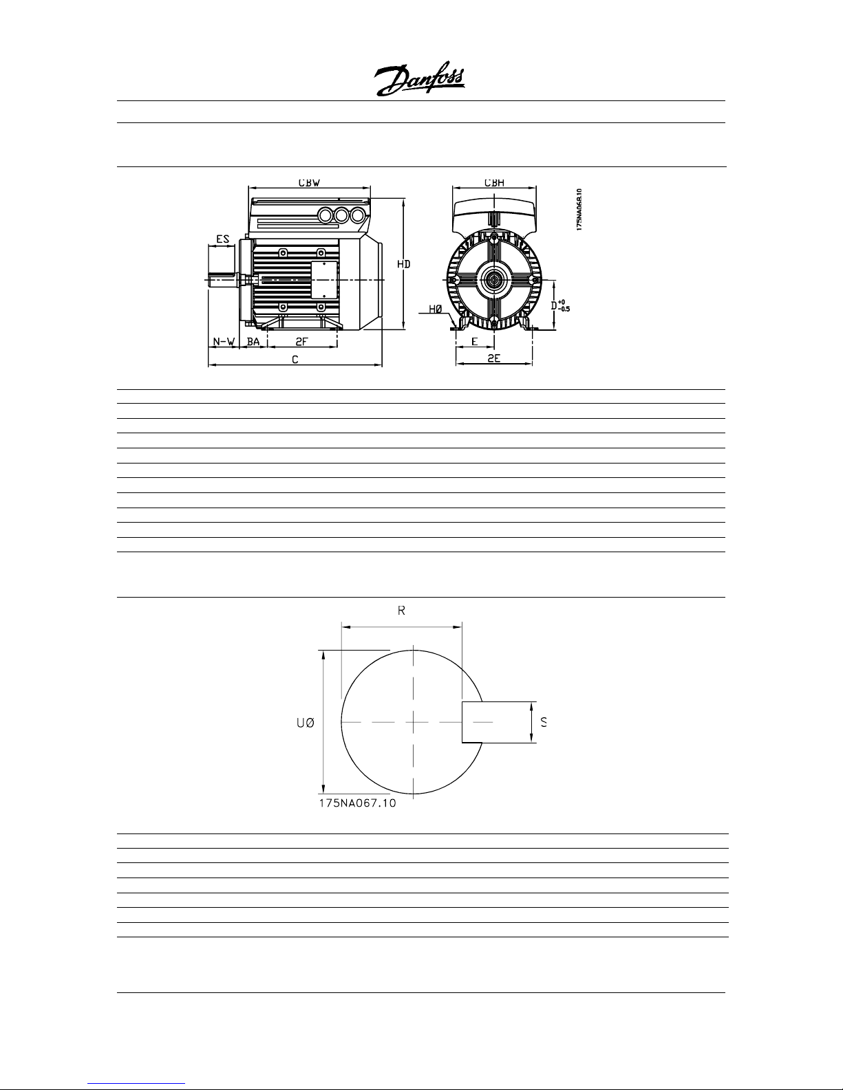
UØ [in] 0.625 0.625 0.875 0.875 1.125 1.125 1.125 1.375 1.375
N-W [in] 1.875 1.875 2.25 2.25 2.75 2.75 2.75 3.25 5.575
ES [in] 1.375 1.375 1.406 1.406 1.75 1.75 1.75 2.375 2.375
S [in] 0.188 0.188 0.188 0.188 0.25 0.25 0.25 0.313 0.313
R [in] 0.517 0.517 0.771 0.771 0.986 0.986 0.986 1.201 1.201
Foot mounting - B3Foot mounting - B3
Foot mounting - B3Foot mounting - B3
Foot mounting - B3
GeneralGeneral
GeneralGeneral
General
FCMFCM
FCMFCM
FCM
305305
305305
305
307307
307307
307
311311
311311
311
315315
315315
315
322322
322322
322
330330
330330
330
340340
340340
340
355355
355355
355
375375
375375
375
Frame sizeFrame size
Frame sizeFrame size
Frame size
5656
5656
56
5656
5656
56
143T143T
143T143T
143T
145T145T
145T145T
145T
NANA
NANA
NA
NANA
NANA
NA
184T184T
184T184T
184T
213T213T
213T213T
213T
215T215T
215T215T
215T
HPHP
HPHP
HP
0.750.75
0.750.75
0.75
1.01.0
1.01.0
1.0
1.51.5
1.51.5
1.5
2.02.0
2.02.0
2.0
--
--
-
--
--
-
5.55.5
5.55.5
5.5
7.57.5
7.57.5
7.5
10.010.0
10.010.0
10.0
2E [in] 4.875 4.875 5.5 5.5 - - 7.5 8.5 8.5
BA [in] 2.75 2.75 2.25 2.25 - - 2.75 3.5 3.5
D [in] 3.5 3.5 3.5 3.5 - - 4.5 5.25 5.25
HØ [in] 0.344 0.344 0.344 0.344 - - 0.5 0.5 0.5
2F [in] 3 3 4 5 - - 4 5.5 7
C [in] 12.25 12.25 13 13 - - 15.78 17.781 17.781
CBW [in] 8.11 8.11 9.06 9.06 - - 11.26 13.38 13.38
CBH [in] 5.55 5.55 6.22 6.22 - - 7.76 9.25 9.25
HD [in] 8,98 8,98 9,31 9,31 11,50 13,14 13,14
Shaft Drive EndShaft Drive End
Shaft Drive EndShaft Drive End
Shaft Drive End
■ Dimensions
3-2
FCM 300 Series
MG.03.B6.2G - VL T is a register ed Danfoss trademark
B14B14
B14B14
B14
FCMFCM
FCMFCM
FCM
305305
305305
305
307307
307307
307
311311
311311
311
315315
315315
315
322322
322322
322
330330
330330
330
340340
340340
340
355355
355355
355
375375
375375
375
Frame sizeFrame size
Frame sizeFrame size
Frame size
5656
5656
56
5656
5656
56
143143
143143
143
145145
145145
145
182182
182182
182
182182
182182
182
184184
184184
184
213213
213213
213
215215
215215
215
HPHP
HPHP
HP
0.750.75
0.750.75
0.75
1.01.0
1.01.0
1.0
1.51.5
1.51.5
1.5
2.02.0
2.02.0
2.0
3.03.0
3.03.0
3.0
4.04.0
4.04.0
4.0
5.55.5
5.55.5
5.5
7.57.5
7.57.5
7.5
10.010.0
10.010.0
10.0
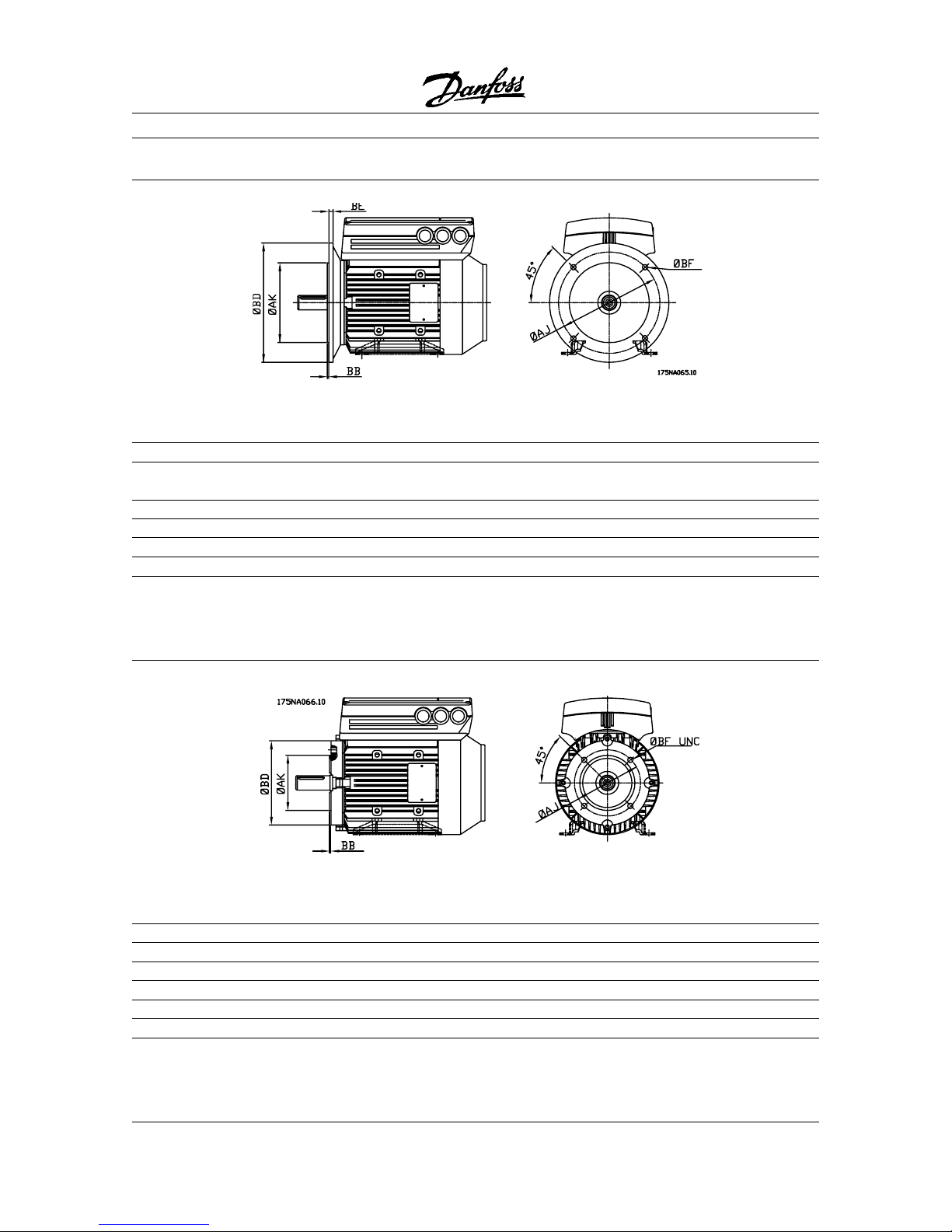
ØAJ [in] 5.575 5.875 8.575 5.875 5.875 7.25 7.25 7.25 7.25
ØAK [in] 4.5 4.5 4.5 4.5 4.5 8.5 8.5 8.5 8.5
ØBD [in] 6.5 6.5 6.5 6.5 6.5 9 9 9 9
ØBF UNC [in] 0.375 0.375 0.375 0.375 0.375 0.5 0.5 0.5 0.5
BB [in] 0.125 0.125 0.125 0.125 0.156 0.156 0.25 0.25 0.25
Flange mounting - B5, B35 (B3+B5)Flange mounting - B5, B35 (B3+B5)
Flange mounting - B5, B35 (B3+B5)Flange mounting - B5, B35 (B3+B5)
Flange mounting - B5, B35 (B3+B5)
B5B5
B5B5
B5
FCMFCM
FCMFCM
FCM
305305
305305
305
307307
307307
307
311311
311311
311
315315
315315
315
322322
322322
322
330330
330330
330
340340
340340
340
355355
355355
355
375375
375375
375
Frame sizeFrame size
Frame sizeFrame size
Frame size
NANA
NANA
NA
NANA
NANA
NA
143143
143143
143
145145
145145
145
182182
182182
182
182182
182182
182
184184
184184
184
213213
213213
213
215 215
215 215
215
HPHP
HPHP
HP
--
--
-
--
--
-
1.51.5
1.51.5
1.5
2.02.0
2.02.0
2.0
3.03.0
3.03.0
3.0
4.04.0
4.04.0
4.0
5.55.5
5.55.5
5.5
7.57.5
7.57.5
7.5
10.010.0
10.010.0
10.0
ØAJ [in] - - 10 10 10 10 10 10 10
ØAK[in] - - 9 999999
ØBD[in] - - 11 11 11 11 11 11 11
ØBF [in] - - 0.531 0.531 0.531 0.531 0.531 0.531 0.531
BB [in] - - 0.25 0.25 0.25 0.25 0.25 0.25 0.25
BE [in] - - 0.5 0.5 0.50 0.50 0.5 0.5 0.5
Face mounting - B14, B34 (B3+B14)Face mounting - B14, B34 (B3+B14)
Face mounting - B14, B34 (B3+B14)Face mounting - B14, B34 (B3+B14)
Face mounting - B14, B34 (B3+B14)
Dimensions
3-3


FCM 300 Series
MG.03.B6.2G - VL T is a register ed Danfoss trademark
Ordering
Chapter 4Chapter 4
Chapter 4Chapter 4
Chapter 4 ■ Ordering information overview .................... page 4-2
■ Product range VLT
®
DriveMotor
FCM 300 Series
..................................... page 4-4
■ Ordering information for
frames and flanges ................................ page 4-6
4-1
FCM 300 Series
MG.03.B6.2G - VLT is a r egistered Danfoss trademark
Ordering Information Overview
■■
■■
■ Code Numbers for 2 Pole Motors with HVAC Parameter Setting H
Type HP Phases Hardw. Foot D Flange C Face Foot & Foot &
Nema Ref Voltage Variant D Flange C Fac
e
FCM305 0.75 ST 176H1578 NA 176H1579 NA 176H1580
56 SP 176H1581 NA 176H1582 N A 176H1583
FCM307 1.0 ST 176H1584 N A 176H1585 NA 176H1586
56 T4 SP 176H1587 NA 176H1588 NA 176H1589
FCM311 1.5 3 phase ST 176H1590 176H1591 176H1592 176H1593 176H1594
143 380-480 V SP 176H1595 176H1596 176H1597 176H1598 176H1599
FCM315 2.0 ST 176H1600 176H1601 176H1602 176H1603 176H1604
145 SP 176H1605 176H1606 176H1607 176H1608 176H1609
FCM322 3.0 ST NA 176H1610 176H1611 NA NA
182 SP NA 176H1612 176H1613 N A NA
FCM330 4.0 ST NA 176H1614 176h1615 NA NA
182 SP NA 176H1616 176H1617 N A NA
FCM340 5.5 ST 176H1618 176H1619 176H1620 176H1621 176H1622
184 SP 176H1623 176H1624 176H1625 176H1626 176H1627
■ Code Numbers for 2 Pole Motors with HVAC Parameter Setting H
4-2
SP 176H1643 176H1644 176H1645 176H1646 176H1647
FCM350 7.5 ST 176H1628 176H1629 176H1630 176H1631 176H1632
213 SP 176H1633 176H1634 176H1635 176H1636 176H1637
FCM375 10.0 ST
215
176H1638 176H1639 176H1640 176H1641 176H1642
Type HP Phases Hardw. Foot D FLange C Face Foot & Foot &
Nema Ref Voltage Variant D Flange C Face
FCM305 0.75 ST 176H1648 NA 176H1649 N A 176H1650
56 SP 176H1651 NA 176H1652 NA 176H1653
FCM311 1.5 T4 ST 176H1660 176H1661 176H1662 176H1663 176H1664
143 3 phase SP 176H1665 176H1666 176H1667 176H1668 176H1669
FCM315 2.0 380-480 V ST 176H1670 176H1671 176H1672 176H1673 176H1674
145 SP 176H1675 176H1676 176H1677 176H1678 176H1679
FCM322 3.0 ST NA 176H1680 176H1681 NA NA
182 SP NA 176H1682 176H1683 NA NA
FCM330 4.0 ST NA 176H1684 176H1685 NA NA
182 SP NA 176H1686 176H167 N A N A
FCM340 5.5 ST 176H1688 176H1689 176H1690 176H1691 176H1692
184 SP 176H1693 176H1694 176H1695 176H1696 176H1697
FCM350 7.5 ST 176H1698 176H1699 176J1700 176H701 176H1702
213 SP 176H1703 176H1704 176H1705 176H1706 176H1707
FCM375 10.0 ST 176H1708 176H1709 176H1710 176H1711 176H1712
215 SP 176H1713 176H1714 176H1715 176H1716 176H1717
FCM307 1.0 ST 176H1654 N A 176H1655 NA 176H1656
56 SP 176H1657 NA 176H1658 NA 176H1659
Ordering
FCM 300 Series
MG.03.B6.2G - VL T is a register ed Danfoss trademark
■■
■■
■ Code Numbers for 2 Pole Motors with Industrial Parameter Setting I
Type H P Phases Hardw. Foot D Flange C Face Foot & Foot &
Nema Ref Voltage Variant D Flange C Face
FCM305 0.75 ST 176H1864 NA 176H1865 N A 176H1866
56 SP 176H1867 NA 176H1868 NA 176H1869
FCM307 1.0 ST 176H1870 N A 176H1871 NA 176H1872
56 SP 176H1873 NA 176H1874 NA 176H1875
FCM311 1.5 T4 ST 176H1876 176H1877 176H1878 176H1879 176H1880
143 3 phase S P 176H1881 176H1882 176H1883 176H1884 176J1885
FCM315 2.0 380-180V ST 176H1886 176H1887 176H1888 176H1889 176H1890
145 SP 176H1891 176H1892 176H1893 176H1894 176H1895
FCM322 3.0 ST NA 176H1896 176H1897 NA NA
182 SP NA 176H1898 176H1899 NA NA
FCM330 4.0 ST NA 176H1900 176H1901 NA NA
182 SP NA 176H1902 176H1903 NA NA
FCM340 5.5 ST 176H1904 176H1905 176H1906 176H1907 176H1908
184 SP 176H1909 176H1910 176H1911 176H1912 176H1913
FCM350 7.5 ST 176H1914 176H1915 176H1916 176H1917 176H1918
213 SP 176H1919 176H1920 176H1921 176H1922 176H1923
FCM375 10.0 ST 176H1924 176H1925 176H1926 176H1927 176H1928
215 SP 176H1929 176H1930 176H1931 176H1932 176H1933
4-3
Type HP Phases Hardw. Foot D Flange C Face Foot & Foot &
Nema Ref Voltage Variant D Flange C Face
FCM305 0.75 ST 176H1934 NA 176H1935 NA 176H1936
56 SP 176H1937 NA 176H1938 N A 176H1939
FCM307 1.0 ST 176H1940 N A 176H1941 NA 176H1942
56 SP 176H1943 NA 176H1944 N A 176H1945
FCM311 1.5 T4 ST 176H1946 176H1947 176H1948 176H1949 176H1950
143 3 phase S P 176H1951 176H1952 176H1953 176H1954 176H1955
FCM315 2.0 380-480 V S T 176H1956 176H1957 176H1958 176H1959 176H1960
145 SP 176H1961 176H1962 176H1963 176H1964 176H1965
FCM322 3.0 ST NA 176H1966 176H1967 NA NA
182 SP NA 176H1968 176H1969 N A NA
FCM330 4.0 ST NA 176H1970 176H1971 NA NA
182 SP NA 176H1972 176H1973 N A NA
FCM 340 5.5 ST 176H1974 176H1975 176H1976 176H1977 176H1978
184 SP 176H1979 176H1980 176H1981 176H1982 176H1983
FCM350 7.5 ST 176H1984 176H1985 176H1986 176H1987 176H1988
213 SP 176H1989 176H1990 176H1991 176H1992 176H1993
FCM375 10.0 ST 176H1994 176H1995 176H1996 176H1997 176H1998
215 SP 176H1999 176H2000 176H2001 176H2002 176H2003
■■
■■
■ Code Numbers for 4 Pole Motors with Industrial Parameter Setting I
Ordering

FCM 300 Series
MG.03.B6.2G - VLT is a r egistered Danfoss trademark
■ Product range VLT® DriveMotor FCM 300 Series,
2/4 poled motors
FCM 355-P-T4-ST-S55-R2-0213T-4-1-B03-213-T-00
This means that the ordered FCM300 is an
FCM355 7,5 HP, three-phase mains voltage of
380 - 480V +/- 10%,
T4 and for process
application
P. The inverter is a standard version
for remote control
ST in a NEMA 12/IP55
enclosure
S55 with integrated RFI filter, class B1
R2. The motor frame size and version is 213T
which is a foot mounted motor
0213T. The motor
has 4 poles
4 and is cooled by the shaft-mounted
fan
1. The motor is a foot mounted motor B03
and the frame is 213. The inverter box is
mounted on the top of the motor
T and no drain
hole is placed
00.
As an example the above motor with D flange,
inverter on the right side, drain hole position
between feet
FCM355-P-T4-ST-S55-R2-0213T-4-1-B05-213R-D1
If you wish to place your order by using the type
code directly, please use the codes given in
parenthesis on the left-hand side of the ordering
forms. The code sequence in the type code is
stated at the top of each part of the form
(character number).
The ordering form for the basic unit must always
be completed. When the type code is written,
always state the characters of the basic string (1-
30).
Together with the order confirmation the
customer receives an 8-figure code number to be
used when reordering.
Type
Motor
Mains supply
output
FCM 305FCM 305
FCM 305FCM 305
FCM 305 0.75 HP
FCM 307FCM 307
FCM 307FCM 307
FCM 307 1.0 HP
FCM 311FCM 311
FCM 311FCM 311
FCM 311 1.5 HP
FCM 315FCM 315
FCM 315FCM 315
FCM 315 2.0 HP
FCM 322FCM 322
FCM 322FCM 322
FCM 322 3.0 HP
3 phase 380-480 V
FCFC
FCFC
FC
M 330M 330
M 330M 330
M 330 4.0 HP
FCM 340FCM 340
FCM 340FCM 340
FCM 340 5.0 HP
FCM 35FCM 35
FCM 35FCM 35
FCM 35
55
55
5 7.5 HP
FCM 37FCM 37
FCM 37FCM 37
FCM 37
55
55
5 10.0 HP
Each type in the product range is available in
different versions.
Inverter versions
Drive control:
-ST: Standard version
- SP: Version for PROFIBUS
RFI filter:
Inverter with integrated RFI filter, class A1 (industrial)
or class B1 (domestic).
Cooling:
- TEFV: Motor cooled by a shaft mounted fan (IC
411)
- FV: Motor cooled by an independent fan (IC 416)
(Not UL)
Mounting versions
- Foot mounting (B3)
- Flange mounting (B5)
- Face mounting (B14)
- Foot + flange mounting (B35)
- Foot + face mounting (B34)
See chapter 6.
Inverter box position: Top, right side or left side.
Drainhole (+ position): None, between feet, opposite
feet, vertical drive end, vertical non-drive end, 90°
right of feet, 90° left of feet.
■■
■■
■ NEMA Ordering
Take a copy of the ordering forms on page 4-8. Fill
in and post or fax your order to the nearest branch
office of the Danfoss sales organisation. On the
basis of your order, the FCM 300 Series motor is
given a type code, which may look as follows:
4-4
Ordering

FCM 300 Series
MG.03.B6.2G - VL T is a register ed Danfoss trademark
Danfoss PC software for serial communication
All FCM 300 Series units come standard with an RS
485 port to communicate with a PC using Danofss
VLT
®
Dialog Software (see page 7-3).
Ordering numbers, VLT® Software Dialog
VLT® Software Dialog 175Z0953
Incl Basic, Logging, Template, Guided tour modules in 6
languages (Danish, English, German, Italian, Spanish and
French)
Accessories for the FC motor
A Local Operation Pad (LOP) for local set point and
start/stop is available for the FC motor. The LOP is
IP 66 enclosed. A Local Control Panel (LCP 2) which
makes up a complete interface for operation,
programming and monitoring of the FC motor is also
available.
Ordering numbers, accessories
Local Operation Pad (LOP) 175N0128
Local Control Panel (LCP 2) 175N0131
Remote mounting kit (LCP 2) 175N0160
Plug kit (LCP 2) 175N0161
Cable for plug kit (LCP 2) 175N0162
Cable (direct mounting) (LCP 2) 175N0165
Service plug kit (LCP 2) 175N0166
4-5
Ordering
PG 16 to ½" NPT adapter 176H9207
PG 21 to 3/4" NPT adapter 176H9208
FCM 300 Series
MG.03.B6.2G - VLT is a r egistered Danfoss trademark
Frame sizes and the corresponding flange sizes for different mounting versions
T ype Frame size version Motor flange size
Foot Flange Face 2 and 4 pole motors
FCM305 00056 NA 0056C 056
FCM307 00056 NA 0056C 056
FCM311 0143T 143TD 143TC 143
FCM315 0145T 145TD 145TC 145
FCM322 NA 182TD 182TC 182
FCM330 NA 182TD 182TC 182
FCM340 0184T 184TD 184TC 184
FCM355 0213T 213TD 213TC 213
FCM375 0215T 215TD 215TC 215
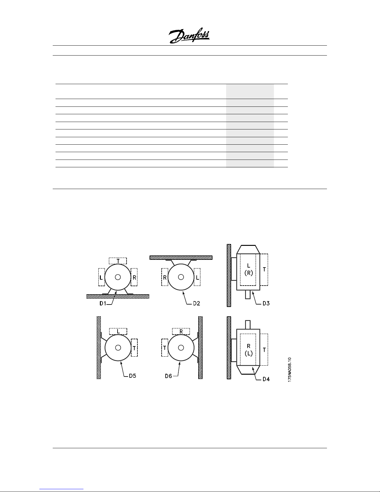
■ NEMA Ordering info for Flange, Face and Foot Versions
■ Ordering info for inverter box position and drain hole position seen from drice end side.
4-6
Ordering
FCM 300 Series
MG.03.B6.2G - VL T is a register ed Danfoss trademark
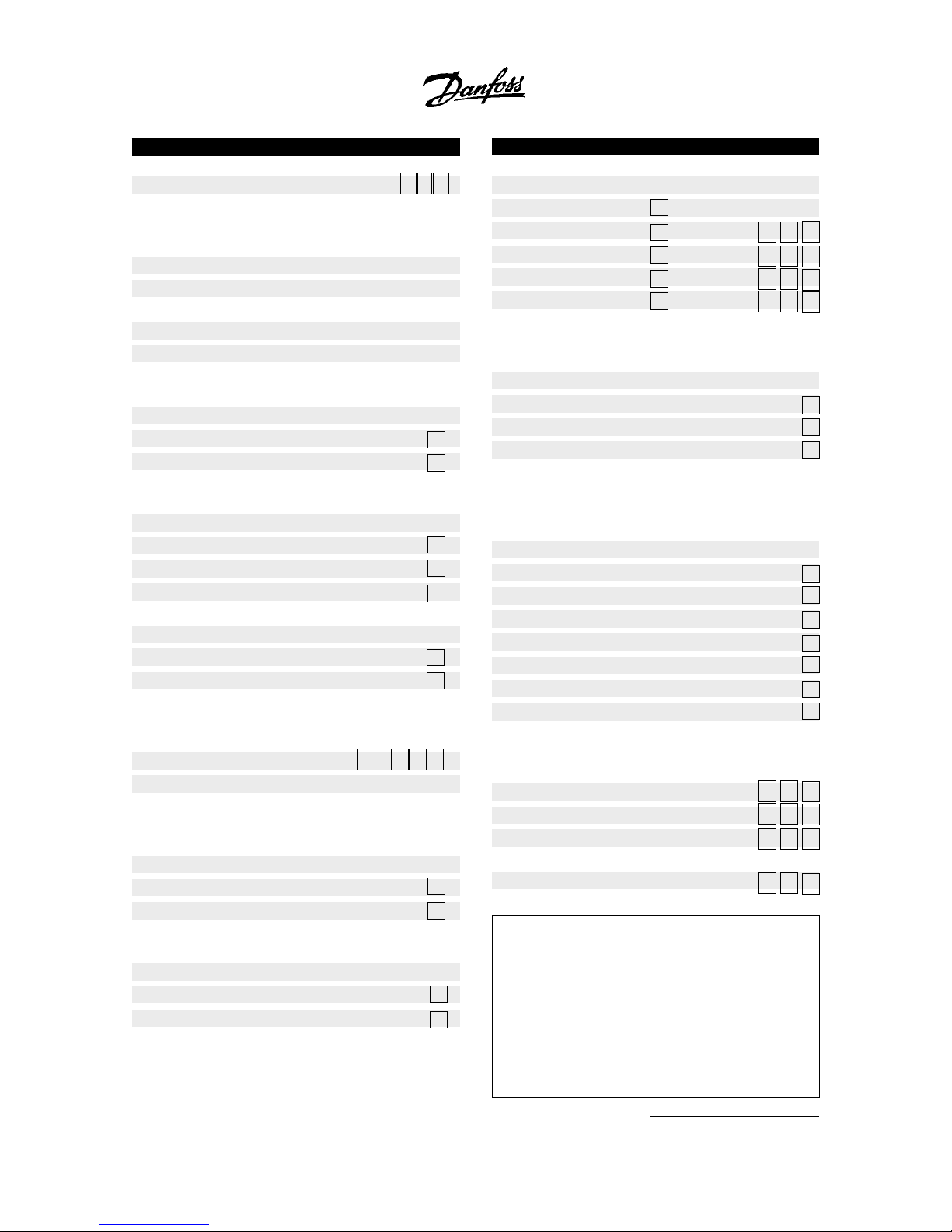
Ordering form FCM 300 Series
Mounting vs. and flange size (char. nos. 24-29)
(B03) Foot 0 0 0
(B05) Flange flange size
(B35) Foot & flange flange size
(B14) Face flange size
(B34) Foot & face flange size
Tick off as appropriate and select flange size from
the table on page 4-7.
Inverter box position (char. no. 30)
(T) Top
(R) Right side
(L) Left side
Tick off as appropriate.
Inverter box position is seen from drive end.
(See drawing on page 4-7).
Drain hole position (char. nos. 31-32)
(00) None
(D1) Between feet
(D2) Opposite feet
(D3) Vertical drive end
(D4) Vertical non-drive end
(D5) 90
° °
° °
° right of feet
(D6) 90
° °
° °
° left of feet
Tick off as appropriate.
(See drawing on page 4-7).
Other options (contact Danfoss for code)
Number of FCM 300 Series ordered
Ordered by:
Ordering form FCM 300 Series
FCM type (character nos. 1-6)
Select the required FCM type from the product
range on the previous page and fill in the squares.
Application range (char. no. 7)
(P) Process
Mains voltage (char. nos. 8-9)
(T4) 3-phase 380-480 V AC
Tick off as appropriate.
Inverter vs. (char. nos. 10-11)
(ST) Standard
(SP) PROFIBUS
Tick off as appropriate.
Enclosure (char. no. 12-14)
(S55) NEMA 12 IP55
(S56) IP56
(S66) IP66
RFI filter (char. nos. 15-16)
(R1) W/ integrated filter, class A1
(R2) W/integrated filter, class B1
Tick off as appropriate.
Frame size and version
(char. nos. 17-21)
Fill in the squares with the appropriate value from
column 2 and 3 in the table on page 4-7.
Polarity (char. no. 22)
(4) 4 poles
(2) 2 poles
Tick off as appropriate.
Cooling (char. no. 23)
(1) (IC 411) Shaft mounted fan
(6) (IC 416) (not UL) Forced ventilation unit
Tick off as appropriate.
Date:
4-7
Ordering


FCM 300 Series
MG.03.B6.2G - VL T is a register ed Danfoss trademark
Chapter 5Chapter 5
Chapter 5Chapter 5
Chapter 5 ■
Product ConceptProduct Concept
Product ConceptProduct Concept
Product Concept
..................................................................
..................................................................
.................................page 5-2
Product Concept
5-1
FCM 300 Series
MG.03.B6.2G - VLT is a r egistered Danfoss trademark
Product Concept
■ Integration of adjustable frequency drive and
motor
The Danfoss VLT
®
adjustable frequency drive
integrated onto the asynchronous motor gives
infinite speed control in one unit.
The VLT
®
FCM 300 Series is a very compact
alternative to the traditional solution with a VLT
adjustable frequency drive and motor as separate
units. The adjustable frequency drive is attached in
place of the motor terminal box, and it is no higher
than the standard terminal box, nor wider or longer
than the motor (see page 3-2).
Installation is made extremely easy. Panel space is
not a problem. There is no need for special details
on wiring to meet the EMC directive, since motor
cables are not necessary. The only connections are
the AC line and control connections.
Factory-set adaption between theadjustable
frequency drive and motor gives precise and energy
efficient control in addition to reducing installation
time.
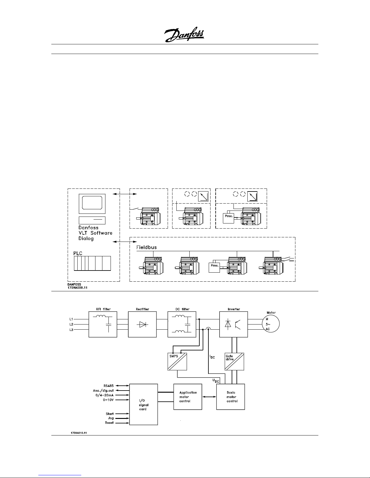
The FCM 300 can be used in stand alone systems
with traditional control signals, such as start/stop
signals, speed references and closed loop process
control or in multiple drive systems with control
signals distributed by a fieldbus.
Combination of fieldbus and traditional control signals
and closed loop PID control is possible. Also possible is a combination fieldbus and traditional control
signals and closed loop PID control.
Control structures
■ Block diagram for FCM 300 Series
■
5-2

FCM 300 Series
MG.03.B6.2G - VL T is a register ed Danfoss trademark
Chapter 6Chapter 6
Chapter 6Chapter 6
Chapter 6 ■
Mechanical InstallationMechanical Installation
Mechanical InstallationMechanical Installation
Mechanical Installation
Mounting Clearances ............................ page 6-2
Alignment .............................................. page 6-2
Maximum axial and radial loads
Standard Ball Bearings ................... page 6-2
Angular Contact Bearings ............... page 6-3
Bolt Torques .......................................... page 6-3
Maintenance......................................... page 6-3
■ Motor information
Motor Description .................................. page 6-4
Handling the FCM 300..........................page 6-5
Bearings................................................ page 6-5
Output Shaf ts ....................................... page 6-5
■ Terminal Scpecifications ........................ page 6-6
Terminal and Switch Locations ............. page 6-6
Connection Diagram ............................. page 6-6
Tightening Torques ................................page 6-7
Maximum Cable Cross Section ............page 6-7
Screw Sizes .......................................... page 6-7
■ Electrical Installation .............................. page 6-8
AC line fuses .........................................page 6-8
Installation
6-1
FCM 300 Series
MG.03.B6.2G - VLT is a r egistered Danfoss trademark
Installation
When the application calls for direct coupling,
the shafts must be correctly aligned in all three
planes. Bad alignment can be a major source of
noise and vibration.
Allowance must be made for shaft endfloat and
thermal expansion in both axial and vertical planes.
It is preferable to use flexible drive couplings.
■ Alignment
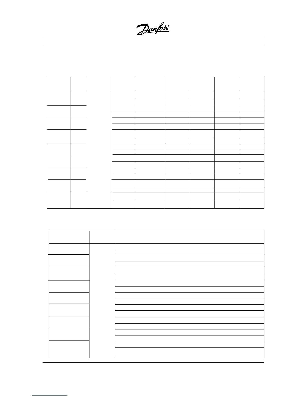
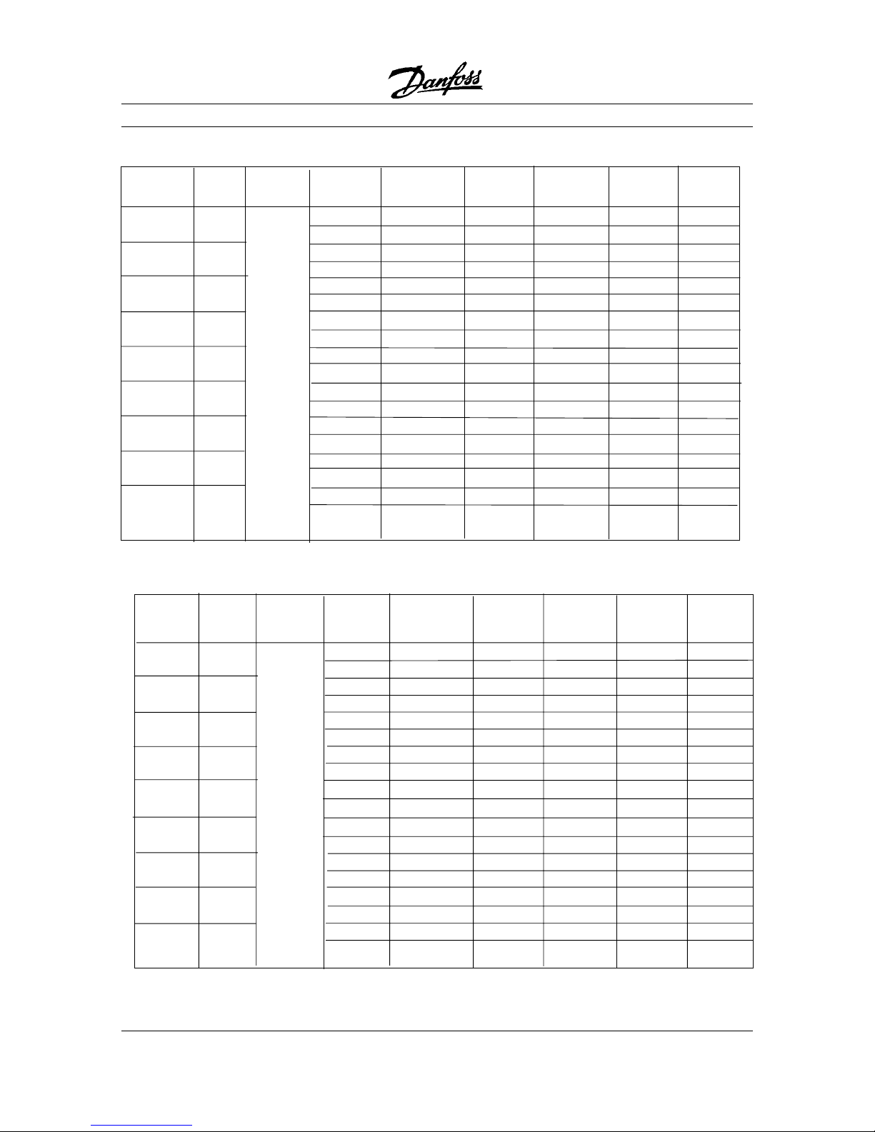
Maximum permissible external axial and radial loads in N (1N = 0.225 lbf) standard ball bearings
Horizontal shaft Vertical shaft
Load towards Load away Shaft up Shaft down
Frame motor from motor load load lo ad load
size Poles Up Down Up Down Max. radial
2
80 2 275 441 481 245 294 432 638
4 373 549 569 343 392 520 785
90 2 412 638 598 294 373 520 824
4 540 765 716 402 471 628 903
100 2 85 3 853 932 9 32 814 814 1207
4 1010 1010 1118 1118 961 961 1393
112 2 85 3 853 932 9 32 814 814 1207
4 1010 1010 1118 1118 961 961 1393
132S 2 1059 1403 1570 95 2 1216 1305 1785
4 1265 1609 1825 1138 1472 1481 1972
132M 4 1256 1609 1854 1109 1501 1462 2040
1
All figures are based on Lna bearing life of 20,000 hours.
Lna = adjusted L10 life rating taking account of:-Reliability -Material improvements -Lubrication conditions
2
Max. permissible radial load at end of shaft (horizontal mounting).
■ Mechanical Installation of the FCM 300
Do not force fittings couplings, pulleys,
etc. onto the FCM 300 motor shaft, as
this will cause bearing damage,
increasing bearing noise and
significantly reducing bearing life.
To avoid overheating, the ambient temperature
should not exceed 104
o
F/40 oC. The average 24-
hour temperature is not to exceed 95
o
F/35 oC. For
more information, see "Derating".
Before installation, check unit for fan cover damage,
foot/mounting damage, shaft damage and loose
fasteners. Check nameplate data on motor.
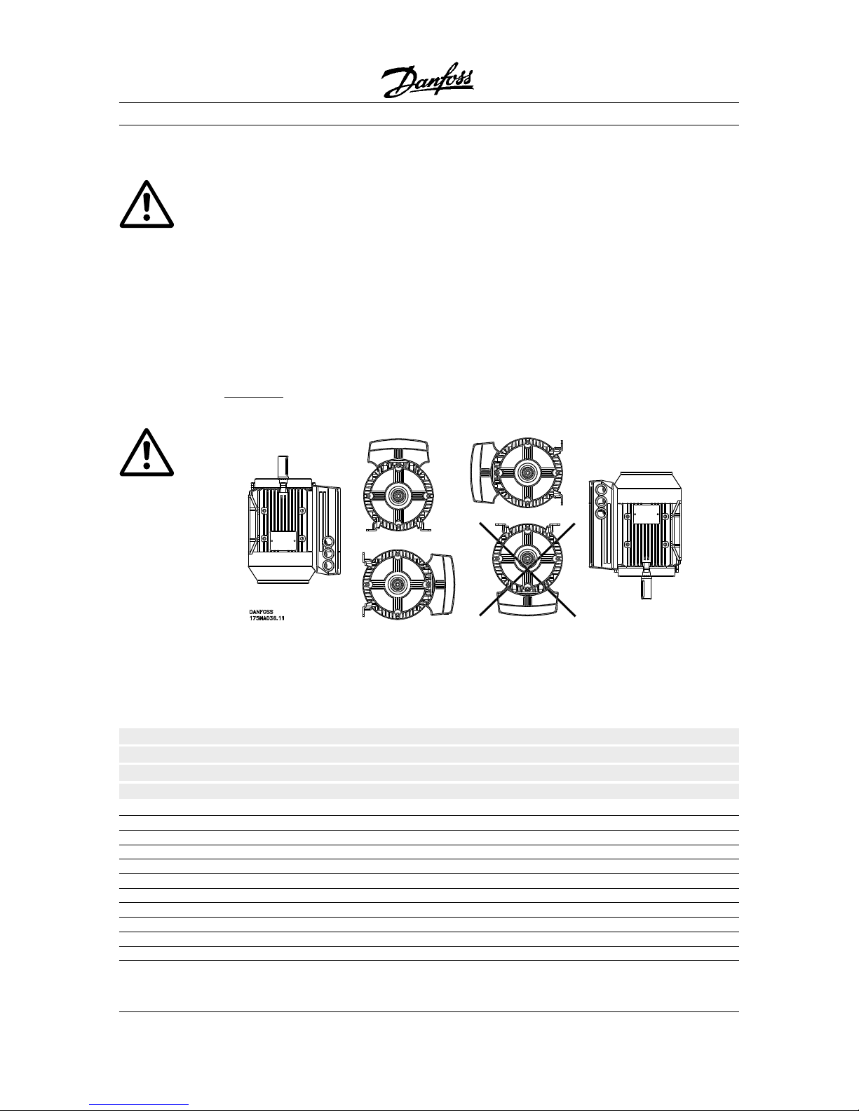
The FCM 300 unit
should not be mounted such that
the inverter portion of the unit (regardless of feet
position) is upside down.
Mounting Clearances
FCM 300 units must be installed with adequate
access for routine maintenance.
Minimum clearance = 29.5 in (0.75 m) on all sides
Minimum clearance at fan inlet = 2 in. (50 mm)
Where several units are installed in close proximity,
care must be taken to ensure warm air from units is
not recirculated.
FCM 300 units must be mounted on rigid, level
surfaces.
Fitting Pinions, Pulleys and Coupling
These should be sized to fit FCM 300 standard
dimensions.
■
■
6-2
FCM 300 Series
MG.03.B6.2G - VL T is a register ed Danfoss trademark
Maximum permissible external axial and radial loads in N (1N = 0.225 lbf) angular contact bearings
Horizontal shaft Vertical shaft
Load towards Load away Shaft up Shaft down
Frame motor from motor load load lo ad load
size Poles Up Down Up Down Max. radial
2
80 2 1375 2205 2405 1225 1470 2160 3190
4 1865 2745 2845 1715 1960 2600 3925
90 2 2060 3190 2990 1470 1865 2600 4120
4 2700 3825 3580 2010 2355 3140 4515
100 2 4265 4265 4660 4660 4070 4070 6035
4 5050 5050 5590 5590 4805 4805 6965
112 2 4265 4265 4660 4660 4070 4070 6035
4 5050 5050 5590 5590 4805 4805 6965
132S 2 5295 7015 7850 4760 6080 6525 8925
4 6325 8045 9125 5690 7360 7405 9860
132M 4 6280 8045 9270 5545 7505 7310 10200
1
All figures are based on Lna bearing life of 20,000 hours.
Lna = adjusted L10 life rating taking account of:-Reliability -Material improvements -Lubrication conditions
2
Max. permissible radial load at end of shaft (horizontal mounting).
Installation
■ Foot Mounting Bolt Torques
Face/Flange, feet and lid should be secured with the
bolt sizes and torque's detailed in the table below.
Foot mounting bolt torques
FCM Type Frame size Bolt diameter Torque
Nm.
305-307 80 M8 (taptite) 24-25
311-315 90 M8 (taptite) 24-25
322-330 100 M8 (taptite) 32-35
340 112 M8 (taptite) 32-35
355-375 132 M8 (taptite) 32-35
Face/Flange bolt torques
FCM Type Frame size Bolt diameter Torque
Nm
305-307 80 M5 5
311-315 90 M5 5
322-330 100 M6 (taptite) 8-10
340 112 M6 (taptite) 8-10
355-375 132 M6 (taptite) 8-10
LID screws torque: 2.2 - 2.4 Nm, Plastic plug (cable entrance) torque: 2.0 Nm
1 Nm = 1.196 lb-ft
■■
■■
■
Maintenance
Routine cleaning of the FCM 300Routine cleaning of the FCM 300
Routine cleaning of the FCM 300Routine cleaning of the FCM 300
Routine cleaning of the FCM 300
Remove the fan cover and ensure that all air inlet
holes are completely clear. Clean any dirt and
obstructions from behind the fan and along the ribs of
the frame, and between the motor and inverter.
Periodic maintenance of motorPeriodic maintenance of motor
Periodic maintenance of motorPeriodic maintenance of motor
Periodic maintenance of motor
..
..
.
a) Remove the inverter , the fan cover and the
fan which is keyed to the shaft extension.
Loosen and remove bearing cover screws and
endshield bolts/studs.The endshields should then
be eased off their spigots.
(b) The rotor can now be carefully withdrawn from
the stator, taking care not to damage the stator
bore and both stator and rotor windings.
(c) Having dismantled the motor, maintenance can
be carried out to remove all dirt. For this
purpose, the use of an air line supplying dry
compressed air under comparatively low
pressure is best, as a high velocity air-stream
can force dirt into the spaces between the
windings and insulation, etc. Grease-removing
solvents can cause damage to impregnating
varnish or insulation
(d) The FCM 300 should be re-assembled in the
reverse order from dismantling, remembering to
ease endshields onto bearings and spigots.
DO NOT USE FORCE.
(e) Before starting, check that the rotor spins
freely . Ensur e that the electrical connections ar e
correct.
(f) Refit any pulley, coupling, spr ocket etc. which
has been removed, being particularly careful to
ensure correct alignment with the driven part,
as misalignment will lead to ultimate bearing
trouble and shaft breakage.
(g) When replacing screws and bolts, care should
be taken to use only those with the grade
recommended by
the manufacturer. These must also be of
identical thread form and screw/bolt length
(see the table above).
6-3
FCM 300 Series
MG.03.B6.2G - VLT is a r egistered Danfoss trademark
Installation
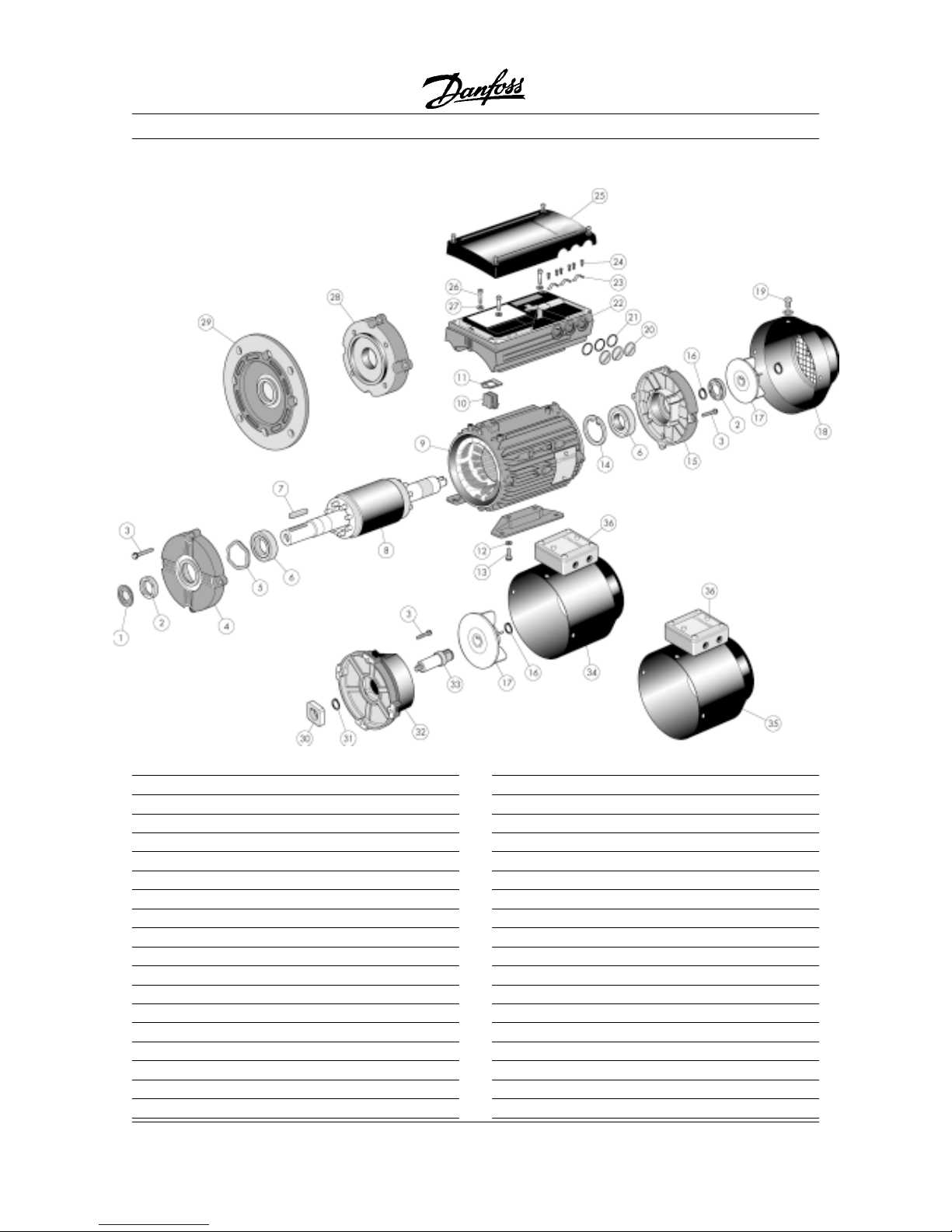
ItemItem
ItemItem
Item
DescriptionDescription
DescriptionDescription
Description
1 Slinger (when fitted)
2 Drive end oilseal
3 Endshield fixing bolt
4 Drive end endshield
5 Preload washer
6 Bearing
7 Shaft key
8 Rotor assembly
9 Stator assembly with or without feet
10 Connector block
11 Gasket
12 Detachable feet
13 Foot mounting bolt and washer
14 Bearing retention circlip
15 Non-drive endshield
16 Bearing circlip
17 Fan
18 Fan cover
ItemItem
ItemItem
Item
DescriptionDescription
DescriptionDescription
Description
19 Fan cover screw and washer
20 Plastic cable entrance plugs
21 O‘ ring
22 ISM box
23 Cable strap
24 Cable strap screws
25 ISM box lid
26 Torx screw
27 Washer
28 Face endshield
29 Flange endshield
30 Brake hub
31 Brake hub retention circlip
32 Brake and adaptor plate
33 Stub shaft
34 Brake fan cover
35 Force vent fan cover
36 Terminal box
■ Motor Information
The FCM 300 consists of the following parts:
6-4

FCM 300 Series
MG.03.B6.2G - VL T is a register ed Danfoss trademark
Handling and lifting of VLT® DriveMotors (FCM 300
units) must only be undertaken by qualified personnel.
Full product documentation and operating instructions
must be available together with tools and equipment
necessary for safe working practice. Eyebolts and/or
lifting points supplied with the FCM 300 are designed
to support only the weight of the FCM 300, not the
weight of the FCM 300 and any auxiliary equipment
attached to it. Be absolutely sure that cranes, jacks,
slings and lifting beams are capable of carrying the
weight of equipment to be lifted.
Where an eyebolt is provided with the motor,
■ Handling the FCM 300
this should be screwed down until its shoulder is
firmly against seated the face of the stator frame to be
lifted.
FCM type approx. weight (kg.) lbs
FCM 305 11 24,3
FCM 307 13 28,7
FCM 311 17 37,5
FCM 315 20 44,1
FCM 322 26 57,3
FCM 330 28 61,7
FCM 340 37 81,6
FCM 355 56 123,5
FCM 375 61 134,5
■■
■■
■
Bearings
To avoid static indention, the storage area should be
vibration free. Where exposure to some vibration is
unavoidable, the shaft should be locked. Bearings
may be fitted with a shaft locking device which
should be kept in place during storage.
Shafts should be rotated by hand, one quarter of a
revolution, at weekly intervals.
Lubrication
FCM Lubrication Temperature
type range
305 - 375 Esso unirex N3 -10 + 140oC/
-14 + 284oF
Bearing life
Maximum hours bearing life (Lna) expected at 80
o
C/176oF bearing temp. x 103 hours.
FCM 3600 rpm 3000 rpm 1800 rpm 1500 rpm
Hori z. Vert . H ori z. Ve rt. Hori z. Ve rt. Horiz.Vert.
305-315 20 20 22 22 30 30 32 32
322-340 22 22 26 26 33 33 35 35
355-375 22 22 26 26 33 33 35 35
Lna bearing life is the adjusted, L10 life rating, taking account of: -Reliability -Material improvement -Lubrication conditions.
Standard Bearing references and oil seals
FCM Mounting Poles (2/4) Bearings Oil seals - Bore x O/D x width in mm
Drive end Non-drive end Drive end Non-drive end
305-307 All All 6204 2Z 6202 2Z 20 x 30 x 7 15 x 24 x 5
311-315 All All 6205 2Z 6203 2Z 25 x 35 x 7 17 x 28 x 6
322-330 All All 6206 2Z 6205 2Z 30 x 42 x 7 25 x 37 x 7
340 All All 6206 2Z 6205 2Z 30 x 42 x 7 25 x 37 x 7
355-375 All All 6208 2Z 6305 2Z 40 x 52 x 7 25 x 37 x 7
■■
■■
■
Output shafts
Output shafts are produced from 35/40 Ton
(460/540 MN/m
2
) tensile steel. Drive end shafts are
provided with a tapped hole to DIN 332 Form D and
a closed profile keyway as standard.
Balance
All motors are dynamically balanced, to ISO 2373
with key convention to IEC 34-14.
InertiaInertia
InertiaInertia
Inertia
FCM J [kgm2]*
2 pole 4 pole
305 0.0015 0.0019
307 0.0015 0.0027
311 0.0024 0.0035
315 0.0024 0.0047
322 0.006 0.009
330 0.007 0.010
340 0.008 0.016
355 0.017 0.027
375 0.020 0.032
Installation
* 1 kgm2 = 23.73036 lbft
2
NOTE!
Ball and roller bearings are shipped from the factory
fully charged with grease. Sealed bearings have
sufficient grease for at least two years of continuous
operation in normal ambient temperatures (see
General Specifications).
6-5

FCM 300 Series
MG.03.B6.2G - VLT is a r egistered Danfoss trademark
Terminal Specifications
To access terminals, remove the inverter top cover,
which is held in place by 4 screws.
Terminal blocks X100 and X101 should be removed
to make the AC Line terminals more accessible.
Lift the corner of the protective black plastic to
expose the AC Line terminals (L1, L2 and L3).
DODO
DODO
DO
NOTNOT
NOTNOT
NOT remove the plastic cover!
Remove necessary
PG plastic plugs to insert AC
Line cable and control cables. Use as many
openings as necessary.
PG to NPT adapters are
sold separately.
Terminal and Switch Locations
X101: Terminal block for analog/digital control signals
Terminal No. Function Example
1 Analog input (0-20 mA) Feedback signal
2 Analog (0-10 V)/digital input 2 Speed reference
3 Digital input (or pulse) 3 Reset
4 Digital input (or precise stop) 4 Start
5 Digital input (other) 5 Jog (fixed speed)
6 24 V DC supply for digital inputs (max. 150 mA)
7 10 V DC supply for potentiometer (max. 15 mA)
8 0 V for terminals 1-7 and 9
9 Analog (0-20 mA)/digital output Fault indication
X100: Terminal block for data communication
Terminal No. Function
1 P RS 485 for connection to
2 N RS 485 bus or PC
3 5 V DC
Supply for RS 485 bus
4 0 V DC
For PROFIBUS versions please refer to the manual
MG90AXYY.
LED 300-304
LED 300 (red): Fault trip
LED 301 (yellow): Warning
LED 302 (green): Power on
LED 303-304: Communication
Reset (pushbutton)
Start
Jog
Speed reference
- Reset to be closed short time for
resetting fault trips
- Start to be closed for changing
to run mode
- Jog will run at fixed speed
while closed (10 Hz)
- Speed reference (0-10 V)
determines speed while in run mode
Connection diagram - factory setting
Screen
For terminating an RS 485 serial communication
interface, units at both ends of the bus must have
their RS 485 switch turned to ON.
The RS 485 connector interfaces with the service
plug kit (part#176N0166) when both serial
communication and the LCP-2 are to be used
simultaneously.
Installation
■
■
■
■
6-6

FCM 300 Series
MG.03.B6.2G - VL T is a register ed Danfoss trademark
Installation
Tightening Torques
Cover (lid) screws: 19.5 - 21.2 lb-in (2.2 - 2.4 Nm)
Plastic cable entrance plugs: 19.5 lb-in (2.2 Nm)
L1, L2, L3 (AC Line) screws (FCM 305-340): 5 - 7 lb-in (0.5 - 0.6 Nm)
L1, L2, L3 (AC Line) screws (FCM 355-375): 15 lb-in (1.2 - 1.5 Nm)
Earth Ground: 30.1 lb-in (3.4 Nm)
Terminal screws require a max 2.5 mm flat-blade screwdriver.
AC Line screws require a 8mm flat-blade screwdriver.
Earth ground and cable clamp screws all require T-20 Torx or flat-blade screwdriver.
Lid screws require Philips screwdriver.
Maximum Cable Cross Section
Note:
Use
o
60 C copper wire or better
AWG mm
2
Max size AC Line cable (FCM 305-340): 10 4.0
Max size AC Line cable (FCM 355-375): 6 10
Max size control cable: 16 1.5
Max size serial communication cable: 16 1.5
Earth Ground: 6 10
Screw Sizes
Cover (lid) screws: M5
Earth Ground and Cable Clamp screws (FCM 305-340): M4
Earth Ground and Cable Clamp screws (FCM 355-375): M5
■
■
■
6-7

FCM 300 Series
MG.03.B6.2G - VLT is a r egistered Danfoss trademark
Installation
The FCM 300 Series unit contains
dangerous voltages when connected
to line voltage. After disconnecting
from the line, wait at least 4 minutes before
touching any electrical components. Also make sure
that other voltage inputs have been disconnected.
Only competent electricians should carry out the
electrical installation. Improper installattion of the
FCM 300 Series unit may cause equipment failure,
serious injury or death. Follow this manual and
National Electrical Codes (NEC
®
) and local safety
codes and guidelines.
To avoid potential shock hazard when servicing the
unit, remove all power to all units that share any
conduit to be worked on.
In general, a conduit should not contain unshielded
power conductors for more than three (3) FCM 300
units.
NOTE:
It is the user's or installer's responsibility to ensure
correct grounding and branch circuit protection in
accordance with national and local codes.
The ground leakage currents are higher than 3.5
mA. This means the FCM 300 requires a fixed,
permant installation, as well as reinforced protective
grounding.
To meet EMC specifications, control cables must be
shielded. Connect the shielded cable to ground at
both ends and use cable clamps.
Before wiring the unit, make sure your supply
voltage corresponds with the voltage requirement of
the FCM 300 unit, TT, IT and TN lines.
Type B RCD's (ELCB relays) or multiple protective
grounding can be used as extra protection of 3
phase equipment with a bridge rectifier and for a
brief discharge on power-up. If RCD's are used,
local regulations must be observed.
Be sure the installation is fused correctly.
Connect the three AC line phases to terminals L1,
L2 and L3 and the ground to the separate earth
ground terminal provided. When power is applied,
the green LED (LED 302) should be lit to indicate
the power is on. In units with built-in Profibus, LED
303 will flash. For further information on Profibus,
pleae see the Profibus manual.
For start-up instructions, please see "Operation" on
page 7-2.
AC Line Fuses
External fuses must be installed in the AC line supply
to the FCM 300 unit.
FCM Type AC Line Voltage Bussmann KTS-R or
JJS Type:
305 380-480 VAC 10 A
307 380-480 VAC 10 A
311 380-480 VAC 10 A
315 380-480 VAC 10 A
322 380-480 VAC 10 A
330 380-480 VAC 15 A
340 380-480 VAC 15 A
355 380-480 VAC 25 A
375 380-480 VAC 25 A
Suitable for use on a circuit capable of delivering not
more than 100,000 rms Symmetrical Amperes, 500
Volts Maximum, when protected by the above
fuses.
■
Electrical Installation
CAUTION!
■
6-8

FCM 300 Series
MG.03.B6.2G - VL T is a register ed Danfoss trademark
Chapter 7Chapter 7
Chapter 7Chapter 7
Chapter 7 ■ Start-up ................................................. page 7-2
■ Control Options .....................................page 7-2
Serial Communication ........................... page 7-2
VLT Dialog and PC ................................ page 7-3
Local Control Panel (LCP-2) .................page 7-3
Local Operation Pad (LOP)................... page 7-4
■ Local Control Panel ...............................page 7-5
Display ................................................... page 7-5
Control Keys ......................................... page 7-6
Control Keys Functions ......................... page 7-6
Display Read-out State ........................ page 7-7
Display Mode ........................................ page 7-7
Quick Menu Mode vs. Menu Mode ...... page 7-8
Parameter Selection ............................. page 7-8
Menu Mode .......................................... page 7-9
Parameter Groups ................................ page 7-9
Change Data ........................................page 7-9
Menu Structure ..................................... page 7-11
Operation
7-1

FCM 300 Series
MG.03.B6.2G - VLT is a r egistered Danfoss trademark
Operation
Start-up
After AC line connections have been made, check
to see that the LED 302 (green) is lit. For Profibus
versions, LED 303 will flash. For more Profibus
information, see the Profibus manual.
For out-of-the-box use without an LOP, LCP-2,
serial communications or PC (see "Control
Options"), simple on/off and speed control is
accomplished as follows:
1. Run cable from terminals 4 and 6 to a start/stop
contact or switch. See diagram below.
2. Wire potentiometer to terminals 2, 7 and 8. See
diagram below.
NOTE
:
Pre-programmed factory parameter settings are
suitable for basic on/off and speed operation as
depicted in the following diagram.
Reset (pushbutton)
Start
Jog
Speed reference
- Reset to be closed short time for
resetting fault trips
- Start to be closed (maintained) for
changing to run mode
- Jog will run at fixed speed
while closed (10 Hz)
- Speed reference (0-10 V)
determines speed while in run mode
Connection diagram - factory setting
NOTE:
Be sure the lid screws are tightened down
sufficiently (19.5 - 21.2 lb-in) to seal lid.
NOTE:
The rotional direction of the motor can not be
changed by switching phases. The default direction
is clockwise. Changing the motor direction must be
programmed in parameter 200.
Control Options
The FCM 300 can be programmed
and operated
with:
1. Serial communication using the RS 485
connection
2. VLT Dialog software and a PC using the RS 485
connection
3. Local Control Panel (LCP-2)
The FCM 300 can be operated, b
ut not
programmed with:
1. Local Operation Pad (LOP) wired to the control
terminals
Serial Communication
Terminal block X100, terminals 1-4 are available for
connecting an RS 485 bus.
■
■
Operation
■
7-2

FCM 300 Series
MG.03.B6.2G - VL T is a register ed Danfoss trademark
Serial Communication (continued...)
For installations that require both serial
communication and use of an LCP-2, the service
plug kit (part #176NO166) and cable (part
#175NO162) provides the necessary interface.
The LCP-2 is attached to the cable and the RS 485
bus is connected to the X100 terminal strip.
Software only: part #175ZO953
Software RS 232/485 converter and cables: part #176F1705
Connect cables from PC to X 100 terminals.
Remote mounting kit
A remote mounting kit (part #175NO160) is available to
mount the LCP-2 on a wall or in a panel.
■
■
VLT Dialog software and PC
VLT Dialog is a powerful drive software tool that allows
set-up, start-up and control of the FCM 300 and other
Danfoss units.
■
Local Control Panel (LCP-2)
The LCP-2 (part #175N0131) is used for programming
and commissioning the FCM 300 units. Use the plug
kit (part #175NO161) and cable (part #175NO162).
The plug kit wires to the X100 terminals. See "Local
Control" on page 7-5 for more information on the LCP-
2.
When serial communication and the LCP-2 are to be
used simultaneously, the service plug kit and cable
provide an alternative connection for the LCP-2. For
more information, see "Serial Communication" on this
page.
NOTE:
The LCP-2 and VLT Dialog can not be used in
conjunction with one another.
Terminal X100/
yellow
green
red
blue
1
4
3
2
D-sub pin
8
3
2
9
Color of wire/
Operation
■
7-3

FCM 300 Series
MG.03.B6.2G - VLT is a r egistered Danfoss trademark
LCP-2
Remote Mounting Kit continued....
Local Operation Pad (LOP)
The LOP is wired directly to the X101 control
terminals. The LOP provides speed control, a start/
stop function and, depending on how it is wired and
programmed, the following three functions:
1. Dual speed operation
2. Dual mode operation (Uses 2-Set-up Menus)
3. Dual direction operation (For forward or reverse)
Color of wireColor of wire
Color of wireColor of wire
Color of wire
TT
TT
T
erminalerminal
erminalerminal
erminal
FunctionFunction
FunctionFunction
Function
White 2 Reference
Brown 3 Reset
Orange or Gray 4 See table under button
Green 5 See table under button
Red 6 +24V
Yellow 7 +10V
Blue 8 Ground
WW
WW
W
iringiring
iringiring
iring
Function/settingsFunction/settings
Function/settingsFunction/settings
Function/settings
Key (Start)Key (Start)
Key (Start)Key (Start)
Key (Start)
Key (Start)Key (Start)
Key (Start)Key (Start)
Key (Start)
Key (Stop)Key (Stop)
Key (Stop)Key (Stop)
Key (Stop)
Default - Dual speed operationDefault - Dual speed operation
Default - Dual speed operationDefault - Dual speed operation
Default - Dual speed operation Run on set Run on Stop (and
(connect orange wire):(connect orange wire):
(connect orange wire):(connect orange wire):
(connect orange wire): reference 10 Hz** reset* - if trip)
No changes to factory setting. (+/- ) jog speed
Function 2 - Dual mode operationFunction 2 - Dual mode operation
Function 2 - Dual mode operationFunction 2 - Dual mode operation
Function 2 - Dual mode operation
(connect orange wire):(connect orange wire):
(connect orange wire):(connect orange wire):
(connect orange wire): Run with Run with Stop (and
Select desired modes of operation Setup 1 Setup 2 reset* - if trip)
in Setups 1 and 2 (use para. 4-6)
Parameter 335 = 18 (select Setup)
Function 3 - Dual direction operationFunction 3 - Dual direction operation
Function 3 - Dual direction operationFunction 3 - Dual direction operation
Function 3 - Dual direction operation
(connect grey wire):(connect grey wire):
(connect grey wire):(connect grey wire):
(connect grey wire): Run Run Stop (and
Parameter 335 = 10 (start reversing) forward reverse reset* - if trip)
Parameter 200 = 1 (both directions)
*If no reset is required, **or set parameter 213
do not connect the brown wire
At power up the unit will always be in stop mode.
Set reference will be stored during power down. If
permanent start mode is desired, connect terminal
6 to terminal 4 and do not connect orange/gray
wire to terminal 4. This means the stop function on
LOP is disabled.
NOTE!
After wiring the LOP, cut off or isolate any
excess wire.
■
■
Operation
7-4

FCM 300 Series
MG.03.B6.2G - VL T is a register ed Danfoss trademark
LCP-2 Functions
The functions of the control panel can be divided
into three groups:
● display
● keys for changing program parameters
● keys for local operation
All data is indicated by means of a 4-line alphanumeric display, which in normal operation is able to
show 4 measurements and 3 operating conditions
continuously. During programming, all the
information required for quick, effective parameter
Local Control
The LCP-2 is an optional control panel for
programming and monitoring the FCM 300 unit.
NOTE:
The VLT 5000 Series LCP (part #175ZO401) can not
be used with the FCM 300. However, the LCP-2
(part #175NO131) can be used with all VLT 5000,
VLT 2800 and FCM 300 Series units.
LCP-2 installation
The LCP-2 is connected to the X100 terminals (1-4).
For more information, see separate instruction
manual MI.03.AX.YY.
Display
The LCD-display is back-lit with 4 alpha-numeric
lines. The display also shows the direction of motor
rotation with an arrow, the active set-up, and the
set-up currently being programmed (can be different
than the active set-up).
12345678901234567890
12345678
12345678901234567890
12345678901234567890
1st line
2nd line
3rd line
4th line
1st line shows up to 3 measurements continuously
in normal operating status or a text which explains
the 2nd line.
2nd line shows a measurement with related unit
continuously, regardless of status (except in the
case of alarm/warning).
■
■
Operation
Setup of the FCM 300 will be displayed. As a
supplement to the display, there are three LEDs for
voltage, warning and alarm.
All program parameters of the FCM 300 can be
changed immediately from the control panel, unless
this function has been blocked via parameter 018.
3rd line is normally blank and is used in the menu
mode to show the selected parameter number or
parameter group number and name.
4th line is used in operating status for showing a
status text or in data change mode for showing the
value of the selected parameter.
An arrow indicates the direction of rotation
of the motor. Furthermore, the Setup
which has been selected as the Active
Setup in parameter 004 is shown. When
programming another Setup than the
Active Setup, the number of the Setup
which is being programmed will appear to the right.
This second Setup number will flash.
LEDs
At the bottom of the control panel is a red alarm
LED and a yellow warning LED, as well as a green
voltage LED.
red yellow green
■
7-5

FCM 300 Series
MG.03.B6.2G - VLT is a r egistered Danfoss trademark
If certain threshold values are exceeded, the alarm
and/or warning lamp is lit together with a status and
alarm text on the control panel.
The green ON LED will be lit when power is applied
to the FCM 300 unit and text will appear on the
back-lit display.
■■
■■
■ Control Keys
The control keys above the line of LEDs are used
for programming. Some parameters can be
changed while the FCM 300 is operating.
■ Control Key Functions
[DISPLAY / STATUS] is used for
selecting the mode of display or for
changing back to Display mode from
either the Quick menu mode or the
Menu mode.
[QUICK MENU] is used for
programming the parameters that
belong under the Quick menu mode.
It is possible to switch directly
between Quick menu mode and
Menu mode.
[MENU] is used for programming all
parameters. It is possible to switch
directly between Menu mode and
Quick menu mode.
[CHANGE DATA] is used for changing
the parameter selected either in the
Menu mode or the Quick menu
mode.
[CANCEL] is used if a change of the
selected parameter is not to be carried
out.
[OK] is used for confirming a change
of the parameter selected.
[+/-] is used for selecting parameter
and for changing the chosen
parameter or for changing the read
out in line 2.
[<>] is used for selecting group and to
move the cursor when changing
numerical parameters.
[STOP / RESET] is used for stopping
or for resetting the FCM 300 after a
drop-out (trip). Can be selected via
parameter 014 to be active or
inactive. If stop is activated, line 2 will
flash, and [START] must be activated.
NOTE!
Pressing [STOP/RESET] will prevent motor from
running also with disconnected LCP-2.
Restarting is only possible via the LCP-2 [START]
key.
[JOG] overrides the output frequency
to a preset frequency while the key is
kept down. Can be selected via
parameter 015 to be active or
inactive.
[FWD / REV] changes the direction of
rotation of the motor, which is
indicated by means of the arrow on
the display although only in Local.
Can be selected via parameter 016 to
be active or inactive (parameter 013
must be set to [1] or [3] and
parameter 200 set to [1].
[START] is used for starting the FCM
300 after stop via the [Stop] key. Is
always active, but cannot override a
stop command given via the terminal
strip.
The four keys below the LED indicators are for local
control of the FCM 300.
Operation
7-6

FCM 300 Series
MG.03.B6.2G - VL T is a register ed Danfoss trademark
NOTE:
Using factory settings, the local control keys (bottom
4 of the display) will be active in Local Control or
Remote Control modes (parameter 002), except for
[FWD/REV] which is only active in Local operation.
All 4 local control keys can be disabled via
parameters 014-017.
NOTE:
Care should be taken when disabling the [STOP]
key! With no external stop function and parameter
014 disabled, the FCM 300 can be started,
but
stopped only by disconnecting power to the motor.
■ Display Read-out State
The display read-out operating values can be
changed via parameters 009-012. A list of
selectable operating values follows:
Operating variable: Unit:
Reference [ %]
Reference [unit]*
Feedback [unit]*
Frequency [Hz]
Frequency x scaling [-]
Motor current [A ]
Torque [% ]
Power [kW]
Power [HP]
Motor voltage [ V ]
DC-link voltage [ V]
FC thermal [%]
Hours run [Hours]
Input status, dig. Input [Binary code]
External reference [%]
Status word [Hex]
Heat sink temp. [ºC]
Alarm word [Hex]
Control word [Hex]
Warning word 1 [Hex]
Warning word 2 [Hex]
Analog input 1 [mA]
Analog input 2 [V ]
*) Select in parameter 416.
The unit is shown in readout state 1 line 1 otherwise 'U'
is shown.
STATUS
VAR 2
VAR 1.1 VAR 1.2 VAR 1.3
Display Mode
During normal operation, up to 4 different operating
variables can be viewed simultaneously on the
display. Each line of the display has a specific
purpose:
••
••
•
Line 1 of the display lists 3 variables: 1.1, 1.2 and 1.3
••
••
• Line 2 gives the fourth variable (shown as VAR 2)
••
••
• Line 4 shows the present operating status or alarms
and warnings.
The number of variables to be viewed on the display is
determined by the read-out state:
Read-out I: II: III:
state:
Line 1 Description Data value Description
for operating for 3 operating for 3 operating
variable in line 2
variables in line 1 variables in line 1
60.0 HZ
FREQUENCY
MOTOR IS RUNNING
Read-out state 1:
This read-out state is standard after start-up or
initializing the unit.
Line 2 provides the operating variable and Line 1
gives a text description of Line 2. The displayed
variable of Line 2 is programmable via parameter
009. Or, the [+/-] keys scroll through the available
variable selections during normal operation.
Operation
■
7-7

FCM 300 Series
MG.03.B6.2G - VLT is a r egistered Danfoss trademark
Read-out state 2:
Press the [DISPLAY/STATUS] key once to activate
read-out state 2. To return to state 1, push the
[DISPLAY/STATUS] key again.
In this state, four operating values are shown at the
same time. In the example, Reference, Torque,
Current and Frequency are selected as variables in
the first and second line.
Read-out state 3:
Continuously hold down the [DISPLAY/STATUS] key
to activate read-out state 3. Releasing the
[DISPLAY/STATUS] key switches the read-out to
state 2. Push the [DISPLAY/STATUS] key once
more to return to state 1.
This state shows the names of the operating
variables that correspond to the values seen in state
2.
Quick Menu Mode vs. Menu Mode
The FCM 300 has many parameters to
accommodate different applications. The Quick
Menu contains the 10 most utilized parameters that
are needed for programming in most applications. If
the parameters in the Quick Menu do not give the
desired functionality, use of the full Menu is always
available.
NOTE:
Some parameters can be utilized in the Menu
mode. For instance, if Open Loop is chosen in
parameter 100, the PID parameters will be hidden.
MOTOR IS RUNNING
60.0 HZ
24.3% 30.2% 13.8A
60.0 HZ
SETUP
1
MOTOR IS RUNNING
REF% TORQUE CURR A
60.0 HZ
SETUP
1
QUICK MENU X OF Y
001 LANGUAGE
ENGLISH
The parameter names and corresponding numbers
(EX Parameter 001 = Language, Parameter 200 =
Direction of rotation) are the same in Quick Setup
Menu and Menu modes.
Changing a parmeter in one mode automatically
changes the same parmeter in the other mode.
Quick Setup via Quick Menu
Initiate the Quick Setup mode by pressing the
[ QUICK MENU] key once, which gives the following
read-out display:
The 3
rd
Line gives the parameter number and name.
The 4
th
Line shows the status/value of the
parameter. After power-up, the Quick Menu will
always start at Position 1 (See "Parameter
Selection" below).
Parameter Selection
Scroll through the Quick Menu parameters by
pressing the [+/-] keys. The parameters and their
positions within the Quick Menu are as follows:
Pos.:No.: Parameter: Unit:
1 001 Language
2 200 Direction of rotation
3 101 Torque characteristic
4 204 Min. reference [Hz]
5 205 Max. reference [Hz]
6 207 Ramp up time [sec.]
7 208 Ramp down time [sec.]
8 002 Local/remote control
9 003 Local reference
10 5 00 Bus address
■
Operation
■
■
7-8

FCM 300 Series
MG.03.B6.2G - VL T is a register ed Danfoss trademark
Menu Mode
Press the [MENU] key once to display the Menu
mode. The display will look like this:
Line 3 of the display shows the parameter group
number and name.
Parameter Groups
The Menu mode parameters are divided into
groups. Scroll through the parameter group (0-6) by
pressing the [<] or [>]keys.
The parameter groups are as follows:
Group no. Parameter group:
0 Operation & Display
1 Load & Motor
2 References & Limits
3 Inputs & Outputs
4 Special functions
5 Serial communication
6 Technical functions
*For information on parameter group 800 and
900 for PROFIBUS, please see the FCM Profibus
manual MG.03.EX.YY.
When the desired parameter group is selected,
push the [+] or [-]keys to obtain access to the
individual parameters.
The 3rd Line of the display shows the parameter
number and name, while the status/value of the
selected parameter is shown in Line 4.
60.0 HZ
FREQUENCY
0..
KEYB. & DISPLAY
FREQUENCY
001 LANGUAGE
60.0 HZ
ENGLISH
FREQUENCY
60.0 HZ
001 LANGUAGE
ENGLISH
Change Data
Regardless of whether a parmeter has been
selected under the Quick Menu or Menu mode, the
procedure for changing data remains the same.
Pressing the [CHANGE DATA] key once will
underline the status/value of the selected parameter
in Line 4 and the text will flash. The next step for
changing the data depends on whether the
selected parameter represents a numerical data
value or a text value.
Changing a Text Value
If the selected parameter is a text value, using the
[+] or [-] keys after the [CHANGE DATA] key has
been pressed will scroll through the possible text
values for that parameter.
The 4
th
Line of the display shows the text value that
will be entered (saved) when the data is accepted.
To accept the data, push the [OK] key once.
■
■
■
■
Operation
7-9

FCM 300 Series
MG.03.B6.2G - VLT is a r egistered Danfoss trademark
60.0 HZ
SETUP
1
FREQUENCY
130 START FREQUENCY
09.0 HZ
60.0 HZ
SETUP
1
FREQUENCY
130 START
10.0 HZ
■■
■■
■ Infinitely variable change of numeric data value
If the chosen parameter represents a numeric data
value, the position (tens, tenths, hundreds, etc.) is
chosen by scrolling with the [<] or [>] keys.
Pressing [<] or [>] keys changes the digit (0-9) of
the selected position:
The digit in the position being altered with flash,
when the 4
th
Line reads the desired value to be
saved, press [OK] once.
Operation
7-10

FCM 300 Series
MG.03.B6.2G - VL T is a register ed Danfoss trademark
■ Menu structure
DISPLAY MODE
MENU MODE
QUICK MENU MODE
DATA CHANGE MODE
▲
▲
▲
▲
▲
▲
▲
▲
Choice of
parameter
DATA MODE
Choice of
data value
Choice of
group
VAR 2
STATUS
VAR 1.1 VAR 1.2 VAR 1.3
60.0 HZ
FREQUENCY
0 KEYB.&DISPLAY
60.0 HZ
QUICK MENU X OF
Y
001 LANGUAGE
ENGLISH
FREQUENCY
001 LANGUAGE
ENGLISH
60.0 HZ
FREQUENCY
001 LANGUAGE
ENGLISH
60.0 HZ
QUICK MENU X OF
Y
001 LANGUAGE
ENGLISH
DATA CHANGE MODE
60.0 HZ
Operation
7-11


FCM 300 Series
MG.03.B6.2G - VL T is a register ed Danfoss trademark
Chapter 8Chapter 8
Chapter 8Chapter 8
Chapter 8 ■ Parameters 001-019 ............................. page 8-2
Parameter Group 0: Operation and Display
8-1
Operation and Display

FCM 300 Series
MG.03.B6.2G - VLT is a r egistered Danfoss trademark
001 Language
(LANGUAGE)
Settings:
✭ English (ENGLISH) [0]
German (DEUTSCH) [1]
French (FRANCAIS) [2]
Danish (DANSK) [3]
Spanish (ESPAÑOL) [4]
Italian (ITALIANO) [5]
State when delivered may vary from factory setting.
Function:
The choice in this parameter defines the language
to be used on the display.
Description of choice:
There is a choice of English [0], German [1], French
[2], Danish [3], Spanish [4] and Italian [5].
Parameter Group 0: Operation & Display
002 Local/remote control
(OPERATION SITE)
Settings:
✭ Remote control (REMOTE) [0]
Local control (LOCAL) [1]
Function:
There is a choice of two methods of controlling the
FCM 300: Remote control [0] and Local control [1].
Description of choice:
If Remote control [0] is selected, the FCM 300 can
be controlled via:
1. The control terminals or the serial communication
port .
2. The [START] key. However, this cannot override
Stop commands (also start-disable) entered via
the digital inputs or the serial communication
port.
3. The [STOP], [JOG] and [RESET] keys, provided
that these are active (see parameters 014, 015
and 017).
If Local control [1] is selected, the FCM 300 can be
controlled via:
1. The [START] key. However, this cannot override
Stop commands on the digital terminals (if [2] or
[4] has been selected in parameter 013).
2. The [STOP], [JOG] and [RESET] keys, provided
that these are active (see parameters 014, 015
and 017).
3. The [FWD/REV] key, provided that this has been
activated in parameter 016 and that in
parameter 013 a choice of [1] or [3] has been
made.
4. Via parameter 003 the local reference can be
controlled by means of the " [ ]" and " [ ]" keys.
✭ = General factory setting - also applying to spare part unit,
HH
HH
H = HVAC setting,
II
II
I = Industrial setting,
( ) = display text [ ] = value for use in communication via serial communication port
How to Read the Parameter Settings
Before working with the parameter settings, it is
important to note that there are various settings
depending on the product.
The standard parameter settings (general factory
settings) are marked with
■
✭ . . These settings are
listed in the back of this manual under "Standard
Parameter Settings".
However, there are some special settings only
applicable for HVAC and industrial products.
Whereever these settings are applied, it is marked
with "
HH
HH
H" for HVAC products and "
II
II
I" for industrial
products.
The settings differing from the standard parameter
settings are also listed in the back of the manual.
NOTE! If H or I is not stated, the standard
parameters settings are to be used.
8-2

FCM 300 Series
MG.03.B6.2G - VL T is a register ed Danfoss trademark
Function:
The choice in this parameter defines the Setup
number you want to control the functions of the
FCM 300.
All parameters can be programmed in two individual
parameter Setups, Setup 1 and Setup 2. In
addition, there is a pre-programmed Setup, called
Factory Setup, that cannot be modified.
Description of choice:
Factory Setup [0] contains the factory data and can
be used as a data source if the other Setups are to
be returned to a known state.
Parameters 005 and 006 allow copying from one
Setup to the other.
Setups 1 [1] and 2 [2] are two individual Setups that
can be selected as required.
Multi-Setup [5] is used if remote-mounting switching
between Setups is desired. Terminals 2, 3, 4, and 5
as well as the serial communication port can be
used for switching between Setups.
005 Programming Setup (EDIT SETUP)
Settings:
Factory Setup (FACTORY SETUP) [0]
Setup 1 (SETUP 1) [1]
Setup 2 (SETUP 2) [2]
✭ Active Setup (ACTIVE SETUP) [5]
Function:
The choice is of the Setup in which programming
(change of data) is to occur during operation. It is
possible to program the two Setups independently
of the Setup selected as the Active Setup (selected
in parameter 004).
Description of choice:
The Factory Setup [0] contains the factory data and
can be used as a data source if the other Setups
are to be returned to a known state.
004 Active Setup (ACTIVE SETUP)
Settings:
Factory Setup (FACTORY SETUP) [0]
✭ Setup 1 (SETUP 1) [1]
Setup 2 (SETUP 2) [2]
Multi Setup (MULTI SETUP) [5]
✭ = General factory setting - also applying to spare part unit,
HH
HH
H = HV AC setting,
II
II
I = Industrial setting, ( ) = parameter
window text. [ ] = value for use in communication via serial communication port
Parameter Group 0: Operation & Display
003 Local reference
(LOCAL REFERENCE)
Settings:
Par 013 set for [1] or [2]:
0 - f
MAX
✭ 000.000
Par 013 set for [3] or [4] and par. 203 = [0] set for
:
Ref
MIN
- Ref
MAX
✭ 000.000
Par 013 set for [3] or [4] and par. 203 = [1] set for:
-Ref
MAX
- + Ref
MAX
✭ 000.000
Function:
This parameter allows manual setting of the desired
reference value (speed or reference for the selected
configuration, depending on the choice made in
parameter 013).
The unit follows the configuration selected in
parameter 100, provided that Process regulation,
closed loop [3] has been selected.
Description of choice:
Local [1] must be selected in parameter 002 for this
parameter to be used.
The set value is saved in the case of a voltage dropout, see parameter 019.
In this parameter Data Change Mode is not exited
automatically (after time out).
Local reference cannot be set via the serial
communication port.
Warning:
Since the value set is remembered
after the power has been cut, the motor
may start without warning when the
power is reinstated; if parameter 019 is changed to
Auto restart, use saved ref. [0].
8-3

FCM 300 Series
MG.03.B6.2G - VLT is a r egistered Danfoss trademark
Setups 1 [1] and 2 [2] are individual Setups which
can be used as required. They can be programmed
freely, regardless of the Setup selected as the Active
Setup and thus controlling the functions of the FCM
300.
NOTE!
If a general change of data or a copying to the
Active Setup is effected, this immediately affects the
functioning of the unit.
006 Copying of Setups (SETUP COPY)
Settings:
✭No copying (NO COPY) [0]
Copy to Setup 1 from # (COPY TO SETUP 1) [1]
Copy to Setup 2 from # (COPY TO SETUP 2) [2]
Copy to Setup all from # (COPY TO ALL) [5]
# = the Setup selected in parameter 005
Function:
A copy is made from the Setup selected in
parameter 005 to one of the other Setups or to all
the other Setups simultaneously.
NOTE!
Copying is only possible in Stop Mode (motor
stopped on a Stop command).
Copying will take max. 3 seconds and has ended
when parameter 006 has returned to value 0.
007 LCP copy (LCP COPY)
Settings:
✭ No copying (NO COPY) [0]
Upload all parameters (UPLOAD ALL PARAM) [1]
Download all parameters (DOWNLOAD ALL) [2]
Download power-independent par.
(DOWNLOAD SIZE INDEP.) [3]
Function:
Parameter 007 is used if it is desired to use the
integrated copying function of the control panel. You
can therefore easily copy parameter value(s) from
one FCM 300 to another.
Description of choice:
Select Upload all parameters [1] if all parameter
values are to be transmitted to the control panel.
Select Download all parameters [2] if all transmitted
parameter values are to be copied to the FCM 300
on which the control panel has been mounted.
Select Download power-independent par. [3] if only
the power-independent parameters are to be
downloaded. This is used if downloading to a FCM
300 that has a different rated power than the one
from where the parameter Setup originates.
NOTE!
Uploading/Downloading can only be carried out in
the Stop mode and only between units with the
same database version (see par. 626 value)
008 Display scaling of motor frequency
(FREQUENCY SCALE)
Settings:
0.01 - 100.00 [ - 10000]
✭ 1.00 [100]
Function:
This parameter chooses the factor to be multiplied
by the motor frequency, f
M
, for presentation in the
display, when parameters 009-012 have been set
for Frequency x Scaling [5].
Description of choice:
Set the desired scaling factor.
009 Display line 2 (DISPLAY LINE 2)
Settings:
None [0]
Reference [%] (REFERENCE [%]) [1]
Reference [unit] (REFERENCE [UNIT]) [2]
Feedback [unit] (FEEDBACK [UNIT]) [3]
✭ Frequency [Hz] (FREQUENCY [Hz]) [4]
Frequency x Scaling [-] (FREQUENCY X SCALE) [5]
Motor current [A] (MOTOR CURRENT [A]) [6]
Torque [%] (TORQUE [%]) [7]
Power [kW] (POWER [kW]) [8]
Power [HP] (POWER [hp] [US]) [9 ]
Motor voltage [V] (MOTOR VOLTAGE [V]) [11]
8-4
✭ = General factory setting - also applying to spare part unit,
HH
HH
H = HVAC setting,
II
II
I = Industrial setting,
( ) = display text [ ] = value for use in communication via serial communication port
Parameter Group 0: Operation & Display

FCM 300 Series
MG.03.B6.2G - VL T is a register ed Danfoss trademark
✭ = General factory setting - also applying to spare part unit,
HH
HH
H = HVAC setting,
II
II
I = Industrial setting,
( ) = display text [ ] = value for use in communication via serial communication port
Parameter Group 0: Operation & Display
DC link voltage [V] (DC LINK VOLTAGE [V]) [12]
Thermal load, FC [%] (FC THERMAL [%]) [14]
Hours run [Hours] (RUNNING HOURS) [15]
Digital input [Binary code] (DIGITAL INPUT [BIN]) [16]
External reference [%] (EXTERNAL REF [%]) [21]
Status word [Hex] (STATUS WORD [HEX]) [22]
Heat sink temp. [°C] (HEA TSINK TEMP [°C]) [25]
Alarm word [Hex] (ALARM WORD [HEX]) [26]
Control word [Hex] (CONTROL WORD [HEX]) [27]
Warning word 1 [Hex]
(WARNING WORD 1 [HEX]) [28]
Warning word 2 [Hex]
(WARNING WORD 2 [HEX]) [29]
Analog input 1 [mA] (ANALOG INPUT 1 [mA]) [30]
Analog input 2 [V] (ANALOG INPUT 2 [V]) [31]
Function:
This parameter allows a choice of the data value to
be displayed in line 2 of the display.
Parameters 010-012 enable the use of three
additional data values to be displayed in line 1.
NOTE!
In parameter 009, "none" [0] cannot be selected.
Description of choice:
ReferenceReference
ReferenceReference
Reference
[%] [%]
[%] [%]
[%] corresponds to the total reference
(sum of digital/analog/preset/bus/freeze ref./catchup and slow-down).
Reference Reference
Reference Reference
Reference
[unit][unit]
[unit][unit]
[unit] gives the sum of the references
using the unit stated on the basis of configuration in
parameter 100 (Hz, Hz and rpm).
FeedbackFeedback
FeedbackFeedback
Feedback
[unit] [unit]
[unit] [unit]
[unit] gives the status value of terminal 1
and 2 using the unit/scale selected in parameter
414, 415 and 416.
FrequencyFrequency
FrequencyFrequency
Frequency
[Hz] [Hz]
[Hz] [Hz]
[Hz] gives the motor frequency, i.e. the
output frequency to the motor.
Frequency x ScalingFrequency x Scaling
Frequency x ScalingFrequency x Scaling
Frequency x Scaling
[-] [-]
[-] [-]
[-] corresponds to the present
motor frequency f
M
multiplied by a factor (scaling) set
in parameter 008.
Motor currentMotor current
Motor currentMotor current
Motor current
[A] [A]
[A] [A]
[A] states the phase current of the
motor measured as effective value.
TT
TT
T
orqueorque
orqueorque
orque
[%] [%]
[%] [%]
[%] gives the current motor load in relation
to the rated motor torque.
PowerPower
PowerPower
Power
[kW] [kW]
[kW] [kW]
[kW] states the actual power consumed by
the motor in kW.
PowerPower
PowerPower
Power
[HP] [HP]
[HP] [HP]
[HP] states the actual power consumed by
the motor in HP.
Motor voltageMotor voltage
Motor voltageMotor voltage
Motor voltage
[V] [V]
[V] [V]
[V] states the voltage supplied to the
motor.
DC link voltageDC link voltage
DC link voltageDC link voltage
DC link voltage
[V] [V]
[V] [V]
[V] states the intermediate circuit
voltage in the FCM 300.
Thermal load, FC Thermal load, FC
Thermal load, FC Thermal load, FC
Thermal load, FC
[%] [%]
[%] [%]
[%] states the calculated/
estimated thermal load on the FCM 300. 100% is
the cut-out limit.
Hours runHours run
Hours runHours run
Hours run
[Hours] [Hours]
[Hours] [Hours]
[Hours] states the number of hours that
the motor has run since the latest reset in
parameter 619.
Digital inputDigital input
Digital inputDigital input
Digital input
[Binary code] [Binary code]
[Binary code] [Binary code]
[Binary code] states the signal states
from the 4 digital terminals (2, 3, 4 and 5). Input 5
corresponds to the bit at the far left. '0' = no signal,
'1' = connected signal.
External referenceExternal reference
External referenceExternal reference
External reference
[%] [%]
[%] [%]
[%] g ives the sum of the external
reference as a percentage (the sum of analog/pulse/
bus).
Status wordStatus word
Status wordStatus word
Status word
[Hex] [Hex]
[Hex] [Hex]
[Hex] gives the status word sent via
the serial communication port in Hex code from the
FCM 300.
Heat sinkHeat sink
Heat sinkHeat sink
Heat sink
temp. temp.
temp. temp.
temp.
[°C] [°C]
[°C] [°C]
[°C] states the present heat sink
temperature of the FCM 300. The cut-out limit is 90 ±
5°C; cutting back in occurs at 60 ± 5°C.
Alarm word Alarm word
Alarm word Alarm word
Alarm word
[Hex][Hex]
[Hex][Hex]
[Hex] indicates one or several alarms in
a Hex code.
Control word. Control word.
Control word. Control word.
Control word.
[Hex] [Hex]
[Hex] [Hex]
[Hex] indicates the control word for
the FC motor. See Serial communication .
Warning word 1.Warning word 1.
Warning word 1.Warning word 1.
Warning word 1.
[Hex] [Hex]
[Hex] [Hex]
[Hex] indicates one or more
warnings in a Hex code.
Warning word 2.Warning word 2.
Warning word 2.Warning word 2.
Warning word 2.
[Hex] [Hex]
[Hex] [Hex]
[Hex] indicates one or more
status states in a Hex code.
Analog input 1 [mA]Analog input 1 [mA]
Analog input 1 [mA]Analog input 1 [mA]
Analog input 1 [mA], states the signal value on
terminal 1.
Analog input 2 [V]Analog input 2 [V]
Analog input 2 [V]Analog input 2 [V]
Analog input 2 [V], states the signal value on
terminal 2.
010 Display line 1.1 (DISPLAY LINE 1.1)
Value:
✭ Reference [%] [1]
See parameter 009.
Function:
This parameter enables a choice of the first of three
data values to be shown on the display, line 1,
position 1.
For display read-outs, press the [DISPLAY/STAT US]
button.
8-5

FCM 300 Series
MG.03.B6.2G - VLT is a r egistered Danfoss trademark
✭ = General factory setting - also applying to spare part unit,
HH
HH
H = HVAC setting,
II
II
I = Industrial setting,
( ) = display text [ ] = value for use in communication via serial communication
Parameter Group 0: Operation & Display
Description of choice:
There is a choice of 24 different data values, see
parameter 009.
011 Display line 1.2 (DISPLAY LINE 1.2)
Value:
✭ Motor current [A] [6]
See parameter 009
Function:
This parameter enables a choice of the second of
the three data values to be shown on the display,
line 1, position 2.
For Display read-outs, press the [DISPLAY/STATUS]
button.
Description of choice:
There is a choice of 24 different data values, see
parameter 009.
012 Display line 1.3 (DISPLAY LINE 1.3)
Value:
H,I Power [HP] [9]
✭ Power [kW] [8]
See parameter 009
Function:
This parameter enables a choice of the third of the
three data values to be shown on the display, line 1,
position 3.
Display read-outs are made by pressing the
[DISPLAY/STATUS] button.
Description of choice:
There is a choice of 24 different data values, see
parameter 009.
013 Local Control/Configuration as
parameter 100 (LOCAL CTRL/CONFIG.)
Value:
Local not active (DISABLE) [0]
LCP control and open loop.
(LCP CTRL/OPEN LOOP) [1]
LCP digital control and open loop.
(LCP+DIG CTRL/OP.LOOP) [2]
LCP control/as parameter 100.
(LCP CTRL/AS P100) [3]
✭ LCP digital control/as parameter 100.
(LCP+DIG CTRL/AS P100) [4]
Function:
This is where the desired function is to be selected if
Local control has been chosen in parameter 002.
See also the description of parameter 100.
Description of choice:
If Local not active [0] is selected, a possible setting
of Local reference via parameter 003 is blocked.
It is only possible to change to Local not active [0]
from one of the other setting options in parameter
013, when the FCM 300 has been set to Remote
control [0] in parameter 002.
LCP control and open loop [1] is used when the
speed is to be adjustable (in Hz) via parameter 003,
when the FCM 300 has been set to Local control [1]
in parameter 002.
If parameter 100 has not been set to Speed
regulation open loop [0], switch to Speed regulation
open loop [0].
LCP digital control and open loop [2] functions as
LCP control and open loop [1], the only difference
being that when parameter 002 has been set to
Local operation [1], the motor is controlled via the
digital inputs.
LCP control/as parameter 100 [3] is selected if the
reference is to be set via parameter 003.
LCP digital control/as parameter 100 [4] functions as
LCP control/as parameter 100 [3], although, when
parameter 002 has been set to Local operation [1],
the motor may be controlled via the digital inputs.
NOTE!
Shift from Remote control to LCP digital control and
open loop:
The present motor frequency and direction of
rotation must be maintained. If the present direction
of rotation does not correspond to the reversing
signal (negative reference), the motor frequency f
M
will be set at 0 Hz.
8-6

FCM 300 Series
MG.03.B6.2G - VL T is a register ed Danfoss trademark
✭ = General factory setting - also applying to spare part unit,
HH
HH
H = HVAC setting,
II
II
I = Industrial setting,
( ) = display text [ ] = value for use in communication via serial communication port
Parameter Group 0: Operation & Display
This parameter disables/enables the local stop
function in question from the control panel.
This key is used when parameter 002 has been set
for Remote control [0] or Local [1].
Description of choice:
If Disable [0] is selected in this parameter, the
[STOP] key will be inactive.
NOTE!
If Enable is selected, the [STOP] key overrules all
Start commands.
015 Local jog (LOCAL JOGGING)
Value:
✭ Not possible (DISABLE) [0]
Possible (ENABLE) [1]
Function:
In this parameter, the jog function can be enabled/
disabled on the control panel.
Description of choice:
If Disable [0] is selected in this parameter, the [JOG]
key will be inactive.
016 Local reversing
(LOCAL REVERSING)
Value:
✭ Not possible (DISABLE) [0]
Possible (ENABLE) [1]
Function:
In this parameter, the reversing function can be
enabled/disabled on the control panel.
This key can only be used if parameter 002 has
been set to Local operation [1] and parameter 013
to LCP control with open loop [1] or LCP control as
parameter 100 [3].
Description of choice:
If Disable [0] is selected in this parameter, the [FWD/
REV] key will be inactive.
See parameter 200.
017 Local reset of trip (LOCAL RESET)
Value:
Not possible (DISABLE) [0]
✭ Possible (ENABLE) [1]
Function:
In this parameter, the reset function can be
selected/removed from the keyboard.
This key can be used when parameter 002 has
been set for Remote control [0] or Local control [1].
Description of choice:
If Disable [0] is selected in this parameter, the
[RESET] key will be inactive.
NOTE!
Only select Disable [0] if an external reset signal has
been connected via the digital inputs.
8-7
Shift from LCP digital control and open loop to
Remote control:
The selected configuration (parameter 100) will be
active. Shifts are effected without any abrupt
movement.
Shift from Remote control to LCP control/as
parameter 100 or LCP digital control/as parameter
100.
The present reference will be maintained. If the
reference
signal is negative, the local reference will be set at
0.
Shift from LCP control/as parameter 100 or LCP
remote control as parameter 100 to Remote control.
The reference will be replaced by the active
reference signal from the remote control.
014 Local stop (LOCAL STOP)
Value:
Not possible (DISABLE) [0]
✭ Possible (ENABLE) [1]
Function:

FCM 300 Series
MG.03.B6.2G - VLT is a r egistered Danfoss trademark
✭ = General factory setting - also applying to spare part unit,
HH
HH
H = HVAC setting,
II
II
I = industrial setting,
( ) = display text [ ] = value for use in communication via serial communication port
Parameter Group 0: Operation & Display
019 Operating state at power up, local
control (POWER UP ACTION)
Value:
H Auto restart, use saved ref.(AUTO RESTART) [0]
✭ Forced stop, use saved ref. (LOCAL=STOP) [1]
Forced stop, set ref. to 0
(LOCAL=STOP, REF=0) [2]
Function:
Setting of the desired operating mode when the
mains voltage is reconnected.
This function can only be active in connection with
Local control [1] in parameter 002.
Description of choice:
Auto restart, use saved ref. [0] is selected if the unit
is to start up with the same local reference (set in
parameter 003) and the same start/stop conditions
(given via the [START/STOP] keys) that the FCM
300 had before it was switched off.
Forced stop, use saved ref. [1] is used if the unit is
to remain stopped when the mains voltage is
connected, until the [STA RT] key is pressed. After
the start command, the local reference used is set
in parameter 003.
018 Lock for data change
(DATA CHANGE LOCK)
Value:
✭ Not locked (NOT LOCKED) [0]
Locked (LOCKED) [1]
Function:
In this parameter, the software can "lock" the
control, which means that data changes cannot be
made via LCP 2 (however, this is still possible via the
serial communication port).
Description of choice:
If Locked [1] is selected, data changes cannot be
made.
8-8
Forced stop, set ref. to 0 [2] is selected if the unit is
to remain stopped when the mains voltage is
connected. Local reference (parameter 003) is
reset.
NOTE!
In remote controlled operation (parameter 002), the
start/stop condition at power up will depend on the
external control signals. If Latched start is selected
in parameter 332-335, the motor will remain
stopped at power up.

FCM 300 Series
MG.03.B6.2G - VL T is a register ed Danfoss trademark
Chapter 9Chapter 9
Chapter 9Chapter 9
Chapter 9 ■ Parameters 100-139 ............................. page 9-2
Parameter Group 1: Load and Motor
9-1
Load and motor

FCM 300 Series
MG.03.B6.2G - VLT is a r egistered Danfoss trademark
100 Configuration (CONFIG. MODE)
Settings:
✭Speed,
open loop mode (SPEED OPEN LOOP) [0]
Process,
closed loop mode (PROCESS CLOSED LOOP) [3]
Function:
This parameter is used for selecting the
configuration to which the FCM 300 is to be
adapted.
Description of choice:
If Speed, open loop mode [0] is selected, a normal
speed control (without feedback signal) is obtained,
but with automatic slip compensation, ensuring a
nearly constant speed at varying loads.
Compensations are active, but may be disabled as
required in parameter 133 - 136.
If Process, closed loop mode [3] is selected, the
internal process regulator will be activated, thereby
enabling accurate regulation of a process with
respect to a given process signal. The process
signal can be set using the actual process unit or as
a percentage. A feedback signal must be supplied
from the process, and the process setpoint must be
adjusted. In process closed loop both directions is
not allowed in parameter 200.
NOTE!
This is only possible in Stop Mode (motor stopped on
a Stop command).
101 Torque characteristics
(TORQUE CHARACT)
Settings:
H Variable torque: high (VAR.TORQUE: HIGH) [4]
★ Constant torque (CONSTANT TORQUE) [1]
Variable torque: low (VAR.TORQUE: LOW) [2]
Var. torque: medium (VAR.TORQUE: MEDIUM) [3]
Function:
In this parameter, the principle for adjusting the U/f
characteristics of the FCM 300 to the torque
characteristics of the load is selected.
Description of choice:
If Constant torque [1] is selected, a load-dependent
U/f characteristic is obtained in which the output
voltage is increased in the case of an increasing
load (current) so as to maintain constant
magnetization of the motor.
Select Variable torque low [2], Variable torque
medium [3] or Variable torque high [4] if the load
follows the square law (centrifugal pumps, fans).
NOTE!
Slip compensation (parameter 136) and start
(parameter 134) are not active if a variable torque is
used.
102 Motor power (MOTOR POWER)
Value:
XX.XX kW - depends on the FCM 300 [XXXX]
Function:
Read only parameter.
103 Motor voltage (MOTOR VOLTAGE)
Value:
XX V- depends on the FCM 300 [XX]
Function:
Read only parameter.
104 Motor frequency (MOTOR FREQUENCY)
Value:
XX.X Hz - depends on the FCM 300 [XXX]
✭ = General factory setting - also applyng to spare part unit,
HH
HH
H = HV AC setting,
II
II
I = Industrial setting, ( ) = parameter
window text. [ ] = value for use in communication via serial communication port
Parameter Group 1: Load and Motor
9-2

FCM 300 Series
MG.03.B6.2G - VL T is a register ed Danfoss trademark
106 Rated motor speed
(MOTOR NOM. SPEED)
Value:
XX rpm - depends on the FCM 300 [XX]
Function:
Read only parameter.
126 DC braking time (DC BRAKING TIME)
Settings:
0.0 - 60.0 sec. [0-600]
✭ 10.0 sec. [100]
Function:
This parameter is for setting the DC braking time for
which the DC braking voltage (parameter 132) is to
be active.
0.0 sec. = OFF
Description of choice:
Set the desired time.
127 DC brake cut-in frequency
(DC BRAKE CUT-IN)
Settings:
0.0 - f
MAX
(parameter 202) [0 - ]
✭ 0.0 Hz = OFF [0]
Function:
This parameter is for setting the DC brake cut-in
frequency at which the DC braking voltage
(parameter 132) is to be active, in connection with a
Stop command.
132 DC braking voltage
(DC BRAKE VOLTAGE)
Settings:
0 - 100 % [0-100]
✭ 0 % [0]
Function:
If the stator in an asynchronous motor is supplied
with DC voltage, a braking torque will accur. The
braking torque depends on the selected DC braking
voltage. The DC braking voltage is stated as a
percentage of maximum braking voltage.
Description of choice:
Set the desired voltage as a specified percentage of
maximum braking voltage.
NOTE!
The DC braking voltage cannot be used as a
holding brake.
✭ = General factory setting - also applying to spare part unit,
HH
HH
H = HV AC setting,
II
II
I = Industrial setting, ( ) = parameter
window text. [ ] = value for use in communication via serial communication port
Description of choice:
Set the desired frequency.
128 Motor thermal protection
(MOTOR THERM. PROTEC.)
Settings:
✭ Disable (DISABLE) [0]
Enable (ENABLE) [1]
Function:
The motor temperature is measured with a
thermistor (optional).
Description of choice:
If Disable [0] is selected no tripping is required when
the motor is overloaded.
Parameter Group 1: Load and Motor
9-3
Function:
Read only parameter.
105 Motor current (MOTOR CURRENT)
Value:
XX.X X A- depends on the FCM 300 [XXXX]
Function:
Read only parameter.

FCM 300 Series
MG.03.B6.2G - VLT is a r egistered Danfoss trademark
134 Start compensation
(START COMP.)
Settings:
0.0 - 300.0 % [0-3000]
✭ 100.0 % [1000]
Function:
The output voltage is compensated as a function of
the load.
NOTE!
If the value is too high the FCM 300 can trip due to
overcurrent.
Description of choice:
Enter a % value.
Rated start compensation = 100 %.
135 U/f ratio (U/F RATIO)
Settings:
0.00 - 20.00 V/Hz [0-2000]
✭ Motor dependent
Function:
The output voltage to the motor can be adjusted on
a linear basis from 0 to rated frequency.
136 Slip compensation
(SLIP COMP.)
Settings:
500.0 - +500.0 % [-5000 - +5000]
✭ 100.0 % [1000]
Function:
The rated slip compensation (factory setting) is
calculated on the basis of the motor parameters.
In parameter 136 the slip compensation can be
adjusted in detail. Optimizing makes the motor
speed less load dependent. This function is not
active at the same time as variable torque
(parameter 101).
Description of choice:
Enter a % value of rated slip compensation.
Parameter Group 1: Load and Motor
✭ = General factory setting - also applying to spare part unit,
HH
HH
H = HV AC setting,
II
II
I = Industrial setting, ( ) = parameter
window text. [ ] = value for use in communication via serial communication port
H
0% [0]
9-4
133 Start voltage (START VOLTAGE)
Settings:
0.00 - 100.00V [0-10000]
✭ Depends on motor
Function:
You can set the motor voltage below the field
weakening point independently of the motor current.
Use this parameter to compensate for too low of
starting torque.
The start voltage is the voltage at 0 Hz.
NOTE!
If the start voltage is set too high, it can lead to
magnetic saturation and motor overheating; the
FCM 300 may trip. Therefore take care when using
the start voltage.
Description of choice:
Set the desired start voltage.

FCM 300 Series
MG.03.B6.2G - VL T is a register ed Danfoss trademark
139 Brake cut in frequency
(BRAKE CUT IN)
Settings:
0.5 - 132 Hz (parameter 200) [5-]
✭ 3.0 Hz [30]
Function:
Here the frequency at which the external brake is to
be activated is selected via output set in parameter
340 when the motor is ramping down to stop.
Description of choice:
Set the desired frequency.
✭ = General factory setting - also applying to spare part unit,
HH
HH
H = HV AC setting,
II
II
I = Industrial setting, ( ) = parameter
window text. [ ] = value for use in communication via serial communication port
Parameter Group 1: Load and Motor
9-5
137 DC holding voltage
(DC HOLD VOLTAGE)
Settings:
0 - 100 % [0-100]
✭ 0 (OFF) % [0]
Function:
This parameter is used to uphold the motor function
(holding torque) or to pre-heat the motor. DC holding
voltage is active at stopped motor when it is set at a
value which is different from 0. Coasting stop will
deactivate the function.
Description of choice:
Enter a percentage value.
138 Brake cut out frequency
(BRAKE CUT OUT)
Settings:
0.5 - 132 Hz (parameter 200) [5-]
✭ 3.0 Hz [30]
Function:
Here the frequency at which the external brake is to
be released is selected via output set in parameter
340 during running.
Description of choice:
Set desired frequency.


FCM 300 Series
MG.03.B6.2G - VL T is a register ed Danfoss trademark
Chapter 10Chapter 10
Chapter 10Chapter 10
Chapter 10 ■ Parameters 200-231 ............................. page 10-2
Parameter Group 2: References and Limits
10-1
References and limits

FCM 300 Series
MG.03.B6.2G - VLT is a r egistered Danfoss trademark
200 Rotation direction (ROTATION)
Settings:
✭Only clockwise,
0-132 Hz (132 Hz CLOCK WISE) [0]
Both directions,
0-132 Hz (132 Hz BOTH DIRECTIONS) [1]
Only counterclockwise, 0-132 Hz
(132Hz COUNTERCLOCKW.) [2]
Function:
This parameter guarantees protection against
unwanted reversing.
Using Process, closed loop mode (parameter 100)
parameter 200 must
not be changed to Both
directions [1].
Description of choice:
Select the desired direction seen from the motor
drive end.
Note that if Only clockwise, 0-132 Hz [0]/Only
counterclockwise, 0-132 Hz [2] is selected, the
output frequency will be limited to the range f
MIN
-
f
MAX
.
If Both directions, 0-132 Hz [1] is selected, the
output frequency will be limited to the range ± f
MAX
(the minimum frequency is of no significance).
NOTE!
This is only possible in Stop Mode (motor stopped on
a Stop command).
201 Min. output frequency
(MIN OUTPUT FREQ)
Settings:
0.0 HZ - f
MAX
(parameter 202)
[0 - ]
✭ 0.0 HZ [0]
H
6.0 Hz [60]
Function:
In this parameter, a minimum motor frequency limit
can be selected that corresponds to the minimum
frequency at which the motor is to run.
✭ = General factory setting - also applying to spare part unit,
HH
HH
H = HV AC setting,
II
II
I = Industrial setting, ( ) = parameter
window text. [ ] = value for use in communication via serial communication port
Parameter Group 2: References and Limits
The minimum frequency can never be higher than
the maximum frequency, f
MAX
.
If Both directions has been selected in parameter
200, the minimum frequency is of no significance.
Description of choice:
A value from 0.0 Hz to the max. frequency selected
in parameter 202 (f
MAX
) can be chosen.
202 Max. output frequency
(MAX OUTPUT FREQ)
Settings:
f
MIN
(parameter 201) - f
RANGE
(132 Hz, par. 200)
✭ f
RANGE
Function:
In this parameter, a maximum motor frequency can
be selected that corresponds to the highest
frequency at which the motor is to run.
See also parameter 205.
Description of choice:
A value from f
MIN
to 132 Hz can be selected.
203 Reference/feedback range
(REF/FEEDB. RANGE)
Settings:
★ Min - Max (MIN - MAX) [0]
- Max - + Max (-MAX-+MAX) [1]
Function:
This parameter decides whether the reference
signal is to be positive or can be both positive and
negative.
NOTE!
Analogue input (reference/feedback) can only be
positive.
Choose Min - Max [0] if Process, closed loop mode
has been selected in parameter 100.
10-2

FCM 300 Series
MG.03.B6.2G - VL T is a register ed Danfoss trademark
Parameter Group 2: References and Limits
204 Minimum reference
(MIN. REFERENCE)
Settings:
-100,000.000 - Ref
MAX
(par. 205) [ -100000000 - ]
H 60.000 [60]
✭ 0.000 [0]
Function:
The Minimum reference gives the minimum setting
that can be assumed by the sum of all references.
Minimum reference is only active if Min - Max [0] has
been set in parameter 203; however, it is always
active in Process, closed loop mode (parameter
100).
Description of choice:
Is only active when parameter 203 has been set to
Min - Max [0].
Set the desired value.
205 Maximum reference
(MAX. REFERENCE)
Settings:
Ref
MIN
(parameter 204)-100,000,000 [-100000000]
H,I 60.000 Hz [60000]
✭ 50.000 H
Z [50000]
Function:
The Maximum reference gives the highest value that
can be assumed by the sum of all references.
If parameter 100 has been selected to open loop
the max. setting is 132 Hz.
If closed loop has been selected the maximum
reference cannot be set higher than the maximum
feedback (parameter 415).
Description of choice:
Set the desired value.
✭ = General factory setting - also applying to spare part unit,
HH
HH
H = HV AC setting,
II
II
I = Industrial setting, ( ) = parameter
window text. [ ] = value for use in communication via serial communication port
207 Ramp-up time (RAMP UP TIME )
Settings:
0.15 - 3600.00 sec. [5 -360000]
H 60.00 sec. [6000]
✭ 3.00 sec. [300]
Function:
The ramp-up time is the acceleration time from 0 Hz
to the rated motor frequency f
M,N
(parameter 104).
This assumes that the current limit is not reached
(to be set in parameter 221).
Description of choice:
Program the desired ramp-up time.
208 Ramp-down time (RAMP DOWN TIME )
Settings:
0.15 - 3600.00 sec. [5 - 360000]
H 60.00 sec. [6000]
✭ 3.00 sec. [300]
Function:
The ramp-down time is the deceleration time from
the rated motor frequency f
M,N
(parameter 104) to 0
Hz provided there is no over-voltage in the inverter
because of regenerative operation of the motor, and
the current limit is not reached (to be set in
parameter 221).
Description of choice:
Program the desired ramp-down time.
10-3
Description of choice:
Choose the desired range.

FCM 300 Series
MG.03.B6.2G - VLT is a r egistered Danfoss trademark
Parameter Group 2: References and Limits
✭ = General factory setting - also applying to spare part unit,
HH
HH
H = HV AC setting,
II
II
I = Industrial setting, ( ) = parameter
window text. [ ] = value for use in communication via serial communication port
213 Jog frequency (JOG FREQUENCY)
Settings:
0.0 HZ - parameter 202 [0 - ]
✭ 10.0 HZ [100]
Function:
The jog frequency f
JOG
is the fixed output frequency
at which the FCM 300 is running when the jog
function is activated.
Description of choice:
Set the desired frequency.
214 Reference function (REF FUNCTION)
Settings:
H External/preset (EXTERNAL/PRESET) [2]
★ Sum (SUM) [0]
Function:
It is possible to define how the preset references are
to be added to the other references. For this
purpose, Sum is used. It is also possible - by using
the External/preset function - to select whether a
shift between external references and preset
references is desired.
Description of choice:
If Sum [0] is selected, one of the adjusted preset
references (parameters 215-216) is added as a
percentage of the maximum possible reference.
If External/preset [2] is selected, it is possible to shift
between external references or preset references
via terminal 2, 3, 4, or 5 (parameter 332, 333, 334,
or 335). Preset references will be a percentage
value of the reference range.
External reference is the sum of the analogue
references, pulses and bus references.
NOTE!
If Sum is selected, one of the preset references will
always be active. If the preset references are to be
without influence, they should be set to 0 % (as in
the factory setting).
10-4
Description of choice:
Program the desired ramp-down time.
211 Jog ramp time (JOG RAMP TIME)
Settings:
0.15 - 3600.00 sec. [5 - 360000]
H 60.00 sec. [6000]
✭ 3.00 sec. [300]
Function:
The jog ramp time is the acceleration/deceleration
time from 0 Hz to the rated motor frequency f
M,N
(parameter 104), provided there is no over-voltage in
the inverter because of regenerative operation of the
motor, and the current limit is not reached (to be set
in parameter 221).
The jog ramp time starts if a jog signal is given via
the digital inputs or the serial communication port.
Description of choice:
Set the desired ramp time.
212 Quick stop ramp-down time
(Q STOP RAMP TIME)
Settings:
0.15 - 3600.00 sec. [5 - 360000]
✭ 3.00 sec. [300]
Function:
The ramp-down time is the deceleration time from
the rated motor frequency to 0 Hz, provided there is
no over-voltage in the inverter because of
regenerative operation of the motor, and the current
limit is not reached (to be set in parameter 221).
Quick-stop is activated by means of a signal on one
of the digital input terminals (2-5), or via the serial
communication port.

FCM 300 Series
MG.03.B6.2G - VL T is a register ed Danfoss trademark
Parameter Group 2: References and Limits
✭ = General factory setting - also applying to spare part unit,
HH
HH
H = HV AC setting,
II
II
I = Industrial setting, ( ) = parameter
window text. [ ] = value for use in communication via serial communication port
215 Preset reference 1 (PRESET REF. 1)
216 Preset reference 2 (PRESET REF. 2)
Settings:
-100.00 % - +100.00 % [-10000 - +10000]
% of the reference range/external reference
✭ 0.00% [0]
Function:
Two different preset references can be programmed
in parameters 215-216.
The preset reference is stated as a percentage of
the value Ref
MAX
or as a percentage of the other
external references, depending on the choice made
in parameter 214. If a Ref
MIN
≠ 0 has been
programmed, the preset reference as a percentage
will be calculated on the basis of the difference
between Ref
MAX
and Ref
MIN
, following which the
value is added to Ref
MIN
.
Description of choice:
Set the fixed reference(s) that is/are to be the
options.
To use the fixed references, it is necessary to have
selected Preset ref. enable on terminal 2, 3, 4, or 5
(parameters 332 - 335).
Choices between fixed references can be made by
activating terminal 2, 3, 4, or 5 - see the table
below.
Terminals 2/3/4/5
Preset reference
Preset reference 1 0
Preset reference 2 1
219 Catch up/slow down value
(CATCH UP/SLW DWN)
Settings:
0.00 - 100.00 % [0 - 10000]
✭ 0.00 % [0]
Function:
This parameter enables the entry of a percentage
value (relative) which will either be added to or
deducted from the actual reference.
Description of choice:
If Catch up has been selected via one of the
terminals 2, 3, 4, or 5 (parameters 332 - 335), the
percentage (relative) value selected in parameter
219 will be added to the total reference.
If Slow down has been selected via one of the
terminals 2, 3, 4, or 5 (parameters 332 - 335), the
percentage (relative) value selected in parameter
219 will be deducted from the total reference.
221 Current limit for motor mode
(CURRENT LIMIT)
Settings:
Min. limit (XX.X) - max. limit (XXX.X)
in % of I
RATED
[XXX - XXXX]
✭ Max. limit (XXX.X) [XXXX]
I
RATED
= rated motor current
Min. limit = magnetizing current in % of I
RATED
Max. limit = unit dependent limit in % of I
RATED
Function:
This function is relevant for all application
configurations; speed and process regulation. This is
where to set the current limit for motor operation.
10-5

FCM 300 Series
MG.03.B6.2G - VLT is a r egistered Danfoss trademark
229 Frequency bypass, bandwidth
(FREQ BYPASS B.W.)
Settings:
0 (OFF) - 100% [0-100]
✭ 0 (OFF) % [0]
Function:
Some systems call for some output frequencies to
be avoided because of resonance problems in the
system.
In parameters 230-231 these output frequencies
can be programmed for bypassing (Frequency
bypass). In this parameter (229), a bandwidth can
be defined on either side of these frequency
bypasses.
Description of choice:
The bypass band is the bypass frequency +/- half
the set bandwidth.
A percentage of the setting in parameters 230-231
is selected.
230 Frequency bypass 1 (FREQ. BYPASS 1)
231 Frequency bypass 2 (FREQ. BYPASS 2)
Settings:
0.0 - 132 Hz (parameter 200) [0 - ]
✭ 0.0 Hz [0]
Function:
Some systems call for some output frequencies to
be avoided because of resonance problems in the
system.
Parameter Group 2: References and Limits
✭ = General factory setting - also applying to spare part unit,
HH
HH
H = HV AC setting,
II
II
I = Industrial setting, ( ) = parameter
window text. [ ] = value for use in communication via serial communication port
Description of choice:
Set the desired % of current.
NOTE!
For motors with 2 poles (0.55 + 1.1 kW), the setting
is limited to 120% which corresponds to 160%
torque, setting 73% corresponds to 100% torque.
10-6
Description of choice:
Enter the frequencies to be avoided.
See also parameter 229.

FCM 300 Series
MG.03.B6.2G - VL T is a register ed Danfoss trademark
Chapter 11Chapter 11
Chapter 11Chapter 11
Chapter 11 ■ Parameters 317-340 ............................. page 11-2
Parameter Group 3: Inputs and Outputs
11-1
Inputs and outputs

FCM 300 Series
MG.03.B6.2G - VLT is a r egistered Danfoss trademark
✭ = General factory setting - also applying to spare part unit,
HH
HH
H = HV AC setting,
II
II
I = Industrial setting, ( ) = parameter
window text. [ ] = value for use in communication via serial communication port
331 Terminal 1, analog input current
(AI [mA] 1 FUNCT)
Settings:
H,I Reference (REFERENCE) [1]
★ No operation (NO OPERATION) [0]
Feedback (FEEDBACK) [2]
Function:
This parameter allows a choice between the
different functions available for the input, terminal 1.
Scaling of the input signal is effected in parameters
338 and 339.
Description of choice:
No operation. Is selected if the FCM 300 is not to
react to signals connected to the terminal.
Reference. Is selected to enable change of
reference by means of an analog reference signal.
If other inputs are connected, these are summed,
taking account of their signs.
Feedback. Is selected if closed loop regulation with
an analog signal is used.
NOTE!NOTE!
NOTE!NOTE!
NOTE!
If Reference or Feedback has been selected on
more than one terminal, these signals will be
summed.
317 Time out
(LIVE ZERO TIME O)
Settings:
1 - 99 sec. [1 - 99]
★10 sec. [10]
Function:
If the value of the reference signal connected to the
input, terminal 1, falls below 50% of the setting in
parameter 336 for a period longer than the time set
in parameter 317, the function selected in
parameter 318 will be activated.
Description of choice:
Set the desired time.
318 Function after time out
(LIVE ZERO FUNCT.)
Settings:
★ Off (OFF) [0]
Stop and trip (STOP AND TRIP) [5]
Function:
This parameter allows a choice of the function to be
activated if the value of the reference signal
connected to the input, terminal 1, falls below 50%
of the setting in parameter 336 for a period longer
than the time set in parameter 317.
If a time-out function (parameter 318) occurs at the
same time as a bus time-out function (parameter
514), the time-out function (parameter 318) will be
activated.
327 32 327
327 Pulse reference/feedback, max. 327 327
327 Pulse reference/feedback, max. frequency
(PULSE REF/FB MAX)
Settings:
100 - 70000 Hz [100 - 70000]
★ 5000 H
Z [5000]
Function:
In this parameter, the signal value is set that
corresponds to the maximum reference/feedback
value set in parameter 205/415.
Description of choice:
Set the desired pulse frequency.
NOTE!
Frequency limit:
Open collector 24 V: 8 kHz
Push pull 24 V: 70 kHz
Parameter Group 3: Inputs and Outputs
11-2

FCM 300 Series
MG.03.B6.2G - VL T is a register ed Danfoss trademark
332 Terminal 2, analog/digital input
(DIGITAL INPUT 2)
333 Terminal 3, digital input
(DIGITAL INPUT 3)
334 Terminal 4, digital input
(DIGITAL INPUT 4)
335 Terminal 5, digital input
(DIGITAL INPUT 5)
Parameter 332 333 334 335
Digital input on terminal no. 2 3 4 5
Settings:
No function (NO OPERATION) [0] [0] [0] [0]
Reset (RESET) [1] ✭ [1] [1] [1]
Coasting stop, inverse (MOTOR COAST INVERSE) [2] [2] [2] [2]
Reset and coasting stop, inverse (RESET & COAST INV.) [ 3] [3] [3] [ 3]
Quick-stop, inverse (QUICK STOP INVERSE) [4] [4] [4] [4]
DC-braking, inverse (DC-BRAKE INVERSE) [5] [5] [5] [5]
Stop inverse (STOP INVERSE) [6] [6] [6] [6]
Start (START) [7] [7] ✭ [7] [7]
Latched start (LATCHED START) [8] [8] [8] [8]
Reversing (REVERSING) [9] [9] [9] [9]
Start reversing (STAR T REVERSING) [10] [10] [10] [10]
Start clockwise, on (ENABLE FORWARD) [11] [11] [11] [11]
Start counter-clockwise, on (ENABLE REVERSE) [12] [12] [12] [12]
Jog (JOGGING) [13] [13] [13] ✭ [13]
Freeze reference (FREEZE REFERENCE) [14] [14] [14] [14]
Freeze output (FREEZE OUTPUT) [15] [15] [15] [15]
Speed up (SPEED UP) [16] [16] [16] [16]
Speed down (SPEED DOWN) [17] [17] [17] [17]
Selection of Setup (SETUP SELECT) [18] [18] [18] [18]
Catch-up (CATCH UP) [19] [19] [19] [19]
Slow-down (SLOW DOWN) [20] [20] [20] [20]
Preset reference (PRESET REF.) [21] [21] [21] [21]
Preset reference, on (PRESET REF. ON) [22] [22] [22] [22]
Precise stop, inverse (PRECISE STOP) [23]
Pulse reference (PULSE REFERENCE) [24]
Pulse feedback (PULSE FEEDBACK) [25]
Analog reference (REFERENCE) ✭ [30]
Analog feedback (FEEDBACK) [31]
Reset and start (RESET AND START) [32] [32] [32] [32]
Function:
In parameters 332-335 it is possible to choose
between the different possible functions related to
the in puts o n ter minal s 2-5. The function options are
shown in the table below.
✭ = General factory setting - also applying to spare part unit,
HH
HH
H = HV AC setting,
II
II
I = Industrial setting, ( ) = parameter
window text. [ ] = value for use in communication via serial communication port
Description of choice:
No functionNo function
No functionNo function
No function is selected if the FCM 300 is not to
react to signals transmitted to the terminal.
Reset Reset
Reset Reset
Reset resets the FCM 300 after an alarm; however,
not all alarms can be reset without disconnecting
from AC Line.
Coasting stop, inverseCoasting stop, inverse
Coasting stop, inverseCoasting stop, inverse
Coasting stop, inverse is used for making the FCM
300 run freely to stop. Logic '0' leads to coasting
stop.
Reset and coasting stop, inverseReset and coasting stop, inverse
Reset and coasting stop, inverseReset and coasting stop, inverse
Reset and coasting stop, inverse, is used for
activating coasting stop at the same time as reset.
Logic ‘0’ leads to coasting stop and reset.
Quick-stop, inverseQuick-stop, inverse
Quick-stop, inverseQuick-stop, inverse
Quick-stop, inverse is used for stopping the motor
in accordance with the quick-stop ramp (set in
parameter 212).
Logic '0' leads to a quick-stop.
Parameter Group 3: Inputs and Outputs
11-3

FCM 300 Series
MG.03.B6.2G - VLT is a r egistered Danfoss trademark
Start counter-clockwiseStart counter-clockwise
Start counter-clockwiseStart counter-clockwise
Start counter-clockwise,
on on
on on
on is used if the motor
shaft is to be able to rotate counter-clockwise when
started.
Should not be used with Process, closed loop
mode.
JogJog
JogJog
Jog is used for overriding the output frequency to
the jog frequency set in parameter 213. The ramp
time can be set in parameter 211. Jog is not active
if a stop command has been given (start-disable).
Jog overrides stand-by.
Freeze referenceFreeze reference
Freeze referenceFreeze reference
Freeze reference - freezes the actual reference.
The frozen reference is now the point of enable/
condition for Speed up and Speed down to be used.
If speed up/down is used, the speed change always
follows the normal ramp (parameters 207/208) in the
range 0 - Ref
MAX.
Freeze outputFreeze output
Freeze outputFreeze output
Freeze output
- freezes the actual motor frequency
(Hz). The frozen motor frequency is now the point of
enable/condition for Speed up and Speed down to
be used.
Freeze output overrides start/stand-by, slip
compensation and closed loop process control.
If speed up/down is used, the speed change always
follows the normal ramp (parameters 207/208) in the
range 0 - f
M,N
.
Speed upSpeed up
Speed upSpeed up
Speed up
and and
and and
and
Speed downSpeed down
Speed downSpeed down
Speed down
are selected if digital
control of the up/down speed is desired (motor
potentiometer). This function is only active if Freeze
reference or Freeze output has been selected.
As long as there is a logic ‘1‘ on the terminal
selected for speed up, the reference or the output
frequency will increase.
As long as there is a logic ‘1‘ on the terminal
selected for speed down, the reference or the
output frequency will be reduced.
Pulses (logic ‘1‘ minimum high for 20 ms and a
minimum pause of 20 ms) will lead to a change of
speed of 0.1% (reference) or 0.1 Hz (output
frequency).
DC braking, inverseDC braking, inverse
DC braking, inverseDC braking, inverse
DC braking, inverse is used for stopping the motor
by energizing it with a DC voltage for a given time,
see parameters 126-127.
Please note that this function is only active if the
settings of parameters 126-127 is different from 0.
Logic '0' leads to DC braking.
Stop inverseStop inverse
Stop inverseStop inverse
Stop inverse is activated by interrupting the voltage
to the terminal. This means that if the terminal has
no voltage, the motor cannot run. The stop will be
effected in accordance with the selected ramp
(parameters 207/208).
None of the above-mentioned stop
commands are to be used
as disconnection switch in connection
with repairs. Disconnect AC Line.
StartStart
StartStart
Start, is selected if a start/stop command is desired.
Logic '1' = start, logic '0' = stop (stand-by).
Latched start Latched start
Latched start Latched start
Latched start - if a pulse is applied for min. 20 ms,
the motor will start, provided no stop command.
The motor stops if Stop inverse is activated briefly.
ReversingReversing
ReversingReversing
Reversing is used for changing the direction of
rotation of the motor shaft. Logic "0" will not lead to
reversing. Logic "1" will lead to reversing. The
reversing signal only changes the direction of
rotation; it does not activate the start function.
Should not be used with Process, closed loop
mode.
Start reversingStart reversing
Start reversingStart reversing
Start reversing, is used for start/stop and for
reversing with the same signal. No start signal is
allowed at the same time. Acts as latch start
reversing, provided latch start has been chosen for
another terminal.
Should not be used with Process, closed loop
mode.
Start clockwiseStart clockwise
Start clockwiseStart clockwise
Start clockwise,
on on
on on
on is used if the motor shaft is only
to be able to rotate clockwise when starting.
Should not be used with Process, closed loop
mode.
Parameter Group 3: Inputs and Outputs
✭ = General factory setting - also applying to spare part unit,
HH
HH
H = HV AC setting,
II
II
I = Industrial setting, ( ) = parameter
window text. [ ] = value for use in communication via serial communication port
11-4

FCM 300 Series
MG.03.B6.2G - VL T is a register ed Danfoss trademark
Selection of Setup,Selection of Setup,
Selection of Setup,Selection of Setup,
Selection of Setup, enables a choice of one of the
two Setups; however, this presupposes that
parameter 004 has been set to Multi Setup.
Catch-up/Slow-downCatch-up/Slow-down
Catch-up/Slow-downCatch-up/Slow-down
Catch-up/Slow-down
is selected if the reference
value is to be increased or reduced by a
programmable percentage value set in parameter
219.
Slow-down Catch-up
Unchanged speed 0 0
Reduced by %-value 1 0
Increased by %-value 0 1
Reduced by %-value 1 1
Preset reference Preset reference
Preset reference Preset reference
Preset reference enables a choice of one of the
two preset references, in accordance with the table
in parameter 215 and 216. To be active, Preset
reference, on has to be selected.
Preset reference, onPreset reference, on
Preset reference, onPreset reference, on
Preset reference, on is used for shifting between
external reference and preset reference. It is
assumed that External/preset [2] has been selected
in parameter 214. Logic '0' = external references
active; logic '1' = one of the two preset references
is active.
Precise stopPrecise stop
Precise stopPrecise stop
Precise stop corrects the ramp-down time to
obtain a high repetitive accuracy of the stopping
point.
Pulse referencePulse reference
Pulse referencePulse reference
Pulse reference is selected if a pulse sequence
(frequency) of 0 Hz is used, corresponding to Ref
MIN
,
parameter 204. The frequency is set in parameter
327, corresponding to Ref
MAX
.
Pulse feedbackPulse feedback
Pulse feedbackPulse feedback
Pulse feedback is selected if a pulse sequence
(frequency) is selected as a feedback signal.
Analog referenceAnalog reference
Analog referenceAnalog reference
Analog reference
is selected to enable change of
reference by means of an analog reference signal.
If other inputs are connected, these are summed,
taking account of their signs.
Analog feedback Analog feedback
Analog feedback Analog feedback
Analog feedback is selected if closed loop
regulation with an analog signal is used.
Reset and start Reset and start
Reset and start Reset and start
Reset and start is used for activating start at the
same time as reset.
Scaling of the input signal is effected in parameters
338 and 339.
NOTE!NOTE!
NOTE!NOTE!
NOTE!
If Reference or Feedback has been selected on
more than one terminal, these signals will be
summed with signs.
336 Terminal 1, min. scaling
(AI 1 SCALE LOW)
Settings:
0.0 - 20.0 mA [0 - 200]
H,I 4.0 mA [40]
★ 0.0 mA [0]
Function:
This parameter determines the value of the
reference signal that is to correspond to the
minimum reference value set in parameter 204.
If the Time-out function of parameter 317 is to be
used, the setting must be > 2 mA.
Description of choice:
Set the desired current value.
337 Terminal 1, max. scaling
(AI 1 SCALE HIGH)
Setting:
0.0 - 20.0 mA [0 - 200]
★ 20.0 mA [200]
Function:
This parameter sets the value of the reference signal
that is to correspond to the maximum reference
value set in parameter 205.
Description of choice:
Set the desired current value.
✭ = General factory setting - also applying to spare part unit,
HH
HH
H = HV AC setting,
II
II
I = Industrial setting, ( ) = parameter
window text. [ ] = value for use in communication via serial communication port
Parameter Group 3: Inputs and Outputs
11-5
Example:
Terminal Freeze ref./
2-5 2-5 Freeze output
No speed change 0 0 1
Speed down 0 1 1
Speed up 1 0 1
Speed down 1 1 1

FCM 300 Series
MG.03.B6.2G - VLT is a r egistered Danfoss trademark
✭ = General factory setting - also applying to spare part unit,
HH
HH
H = HV AC setting,
II
II
I = Industrial setting, ( ) = parameter
window text. [ ] = value for use in communication via serial communication port
339 Terminal 2, max. scaling
(AI 2 SCALE HIGH)
Settings:
0.0 - 10.0 V [0 - 100]
★ 10.0 V [100]
Function:
This parameter is used for setting the signal value
that corresponds to the maximum reference value
set in parameter 205.
Description of choice:
Set the desired voltage value.
340 Terminal 9, output functions (OUTPUT FUNC.)
Settings:
✭No function (NO OPERATION) [0]
Ready signal (UNIT READY) [1]
Enable, no warning (ENABLE/NO WARNING) [2]
H,I Running (MOTOR RUNNING) [3]
Running, no warning (RUNNING NO WARNING) [4]
Running on reference, no warning (RUNNING ON REFERENCE) [5]
Fault (FAULT) [6]
Fault or warning (FAULT OR WARNING) [7]
Current limit (CURRENT LIMIT) [8]
Thermal warning (THERMAL WARNING) [9]
Reversing (REVERSE) [10]
Off 123 (OFF 123 RELAY) [11]
Actual frequency 0-20 mA (0-FMAX = 0-20 mA) [12]
Actual frequency 4-20 mA (0-FMAX = 4-20 mA) [13]
Reference
MIN
- reference
MAX
: 0-20 mA (REF MIN-MAX =0-20 mA) [14]
Reference
MIN
- reference
MAX
: 4-20 mA (REF MIN-MAX =4-20 mA) [15]
Feedback
MIN
- feedback
MAX
: 0-20 mA (FB MIN-MAX =0-20 mA) [16]
Feedback
MIN
- feedback
MAX
: 4-20 mA (FB MIN-MAX =4-20 mA) [17]
Actual current 0-20 mA (0-IMAX = 0-20 mA) [18]
Actual current 4-20 mA (0-IMAX = 4-20 mA) [19]
Mechanical brake (MECHANICAL BRAKE) [20]
Function:
This output can act both as a digital and an analog
output. If used as a digital output (data value [0][11]), a 24 V DC signal is transmitted; if used as an
analog output (DATA VALUE [12]-[20]) either a 0-20
mA signal, or a 4-20 mA signal output.
Description of choice:
Unit Ready signal, the FCM 300 is ready for use.
Enable/no warning, the FCM 300 is ready for use;
no start or stop command has been given (start/
disable). No warning.
Motor Running, the output frequency is higher than
0.1 Hz. A start command has been given.
Running no warning, the output frequency is higher
than 0.1Hz. A start command has been given. No
warning.
Running on reference, no warning, speed according
to reference. No warning.
Fault, output is activated by alarm.
Fault or warning, the output is activated by alarm or
warning.
Parameter Group 3: Inputs and outputs
11-6
338 Terminal 2, min. scaling
(AI 2 SCALE LOW)
Settings:
0.0 - 10.0 V [0 - 100]
★ 0.0 V [0]
Function:
This parameter is used for setting the signal value
that corresponds to the minimum reference value
set in parameter 204.
Description of choice:
Set the desired voltage value.

FCM 300 Series
MG.03.B6.2G - VL T is a register ed Danfoss trademark
Off 123 relay, if Profidrive [0] has been selected in
parameter 512, the output is activated. If either
OFF1, OFF2 or OFF3 (bit in the control word) is logic
'1'.
0-f
MAX
(parameter 202) ⇒ 0-20 mA and
0-f
MAX
(parameter 202) ⇒ 4-20 mA
Reference
MIN
- Reference
MAX
: 0-20 mA and
Reference
MIN
- Reference
MAX
: 4-20 mA
Feedback
LOW
- Feedback
HIGH
: 0-20 mA and
Feedback
LOW
- Feedback
HIGH
: 4-20 mA
0-I
VLT, MAX
⇒ 0-20 mA and
0-I
VLT, MAX
⇒ 4-20 mA
Mechanical brake, enables control of an optional
external mechanical brake (see also parameter 138
and 139).
Parameter Group 3: Inputs and Outputs
11-7
Current limit, the current limit in parameter 221 has
been exceeded.
Thermal warning, above the temperature limit in the
frequency converter.
Reverse. Logic '1' = relay activated, 24 V DC on the
output when the direction of rotation of the motor is
clockwise. Logic '0' = relay not activated, no signal
on the output, when the direction of rotation of the
motor is counter-clockwise.
✭ = General factory setting - also applying to spare part unit,
HH
HH
H = HV AC setting,
II
II
I = Industrial setting, ( ) = parameter
window text. [ ] = value for use in communication via serial communication port


FCM 300 Series
MG.03.B6.2G - VL T is a register ed Danfoss trademark
Chapter 12Chapter 12
Chapter 12Chapter 12
Chapter 12 ■ Parameters 400-446 ............................. page 12-2
Parameter Group 4: Special Functions
12-1
Special functions

FCM 300 Series
MG.03.B6.2G - VLT is a r egistered Danfoss trademark
✭ = General factory setting - also applying to spare part unit,
HH
HH
H = HV AC setting,
II
II
I = Industrial setting, ( ) = parameter
window text. [ ] = value for use in communication via serial communication port
405 Reset function (RESET MODE)
Settings:
H Automatic reset x 10 (AUTOMATIC X 10) [10]
★ Manual reset (MANUAL RESET) [0]
Automatic reset x 1 (AUTOMATIC X 1) [1]
Automatic reset x 2 (AUTOMATIC X 2) [2]
Automatic reset x 3 (AUTOMATIC X 3) [3]
Automatic reset x 4 (AUTOMATIC X 4) [4]
Automatic reset x 5 (AUTOMATIC X 5) [5]
Automatic reset x 6 (AUTOMATIC X 6) [6]
Automatic reset x 7 (AUTOMATIC X 7) [7]
Automatic reset x 8 (AUTOMATIC X 8) [8]
Automatic reset x 9 (AUTOMATIC X 9) [9]
Reset at power-up (RESET AT POWER UP) [11]
Function:
This parameter makes it possible to select the reset
function desired after tripping.
After reset, the FCM 300 can be restarted after 1.5
sec.
Description of choice:
If Manual reset [0] is selected, reset must be
effected via the digital inputs.
If the FCM 300 is to carry out an automatic reset
(max. 1-10 times within 10 minutes) after tripping,
select data value [1]-[10].
Warning:
The motor may start without
warning up to 10 x 5 sec. after trip.
411 Switching frequency (SWITCH FREQ.)
Settings:
1.5 -14.0 kHz [1500 - 14000]
★ Unit dependent
Function:
The setting determines the switching frequency of
the inverter. If the switching frequency is changed,
this may help to minimize possible acoustic noise
from the motor.
Description of choice:
When the motor is running, the switching frequency
is adjusted in parameter 411 until the frequency has
been obtained at which the motor is as low-noise as
possible.
See also parameter 446 - switching pattern.
NOTE!
Switching frequencies higher than 4 kHz may cause
thermal trip depending on ambient temperature.
412 Variable switching frequency
(VAR CARRIER FREQ)
Settings:
Not possible (DISABLE) [0]
Variable switching freq. (VAR. CARRIER FREQ.) [1]
★ Temperature dep. sw. freq. (TEMP. DEP. FREQ.) [2]
Function:
This function makes it possible to change the
switching frequency depending on the load.
However, the maximum switching frequency is
determined by the value set in parameter 411.
Description of choice:
Select Not possible [0] if a permanent switching
frequency is desired. Set the switching frequency in
parameter 411.
If Variable switching frequency [1] is selected the
switching frequency will decline at an increasing
output frequency. This is used in applications with
square torque characteristics (centrifugal pumps and
fans) in which the load declines depending on the
output frequency.
Parameter Group 4: Special functions
400 Brake functions (BRAKE FUNCTIONS)
Settings:
★ OFF (OFF) [0]
AC brake (AC BRAKE) [4]
Function:
Description of choice:
AC brake [4] can be selected to improve braking.
Select AC brake [4] if short-term generated loads
occur.
12-2

FCM 300 Series
MG.03.B6.2G - VL T is a register ed Danfoss trademark
✭ = General factory setting - also applying to spare part unit,
HH
HH
H = HV AC setting,
II
II
I = Industrial setting, ( ) = parameter
window text. [ ] = value for use in communication via serial communication port
413 Overmodulation function
(OVERMODULATION)
Settings:
Off (OFF) [0]
★ On (ON) [1]
Function:
This parameter allows activation of the
overmodulation function for the output voltage.
Description of choice:
Off means that there is no overmodulation of the
output voltage, which means that torque ripple on
the motor shaft is avoided. This can be a good
feature, e.g. on grinding machines.
On means that an output voltage can be obtained
which is greater than the mains voltage (up to 5%).
414 Minimum feedback
(MIN. FEEDBACK)
Settings:
-100,000,000 - FB
HIGH
(par. 415) [-100000000 - ]
★ 0.000 [0]
Function:
Parameters 414 and 415 are used to scale the
feedback range to physical values used by the user.
The setting will also be the bounds of the reference
(parameters 204 and 205).
Parameter Group 4: Special functions
416 Reference/feedback unit
(REF/FEEDB. UNIT)
Settings:
NO UNIT [0] t/min [21]
★ % [1] t/h [22]
PPM [2] m [23]
RPM [3] Nm [24]
bar [4] m/s [25]
CYCLE/min [5] m/min [26]
PULSE/s [6] °F [27]
UNITS/s [7] in wg [28]
UNITS/min [8] gal/s [29]
UNITS/h [9] ft
3
/s [30]
°C [10] gal/min [31]
Pa [11] ft
3
/min [32]
l/s [12] gal/h [33]
m
3
/s [13] ft3/h [34]
l/min [14] lb/s [35]
m
3
/min [15] lb/min [36]
l/h [16] lb/h [37]
m
3
/h [17] lb ft [38]
kg/s [18] ft/s [39]
kg/min [19] ft/min [40]
kg/h [20] Hz [41]
Function:
Choose among different units to be shown on the
display.
This unit is also used directly in Process regulation,
closed loop as a unit for Minimum/Maximum
reference (parameters 204/205) and Minimum/
Maximum feedback (parameters 414/415).
Description of choice:
Is only active when parameter 203 has been set to
Min-Max [0].
415 Maximum feedback
(MAX. FEEDBACK)
Settings:
(par. 414) FB
LOW
- 100,000,000 [ - 100000000]
H,I 100.000 [100000]
✭ 1.500.000 [1500000]
Function:
See description of parameter 414.
If Temperature dependent switching frequency [2] is
selected, the switching frequency will decline at an
increasing inverter temperature, see the drawing
below.
12-3
Used together with Process, closed loop mode
(parameter 100).

FCM 300 Series
MG.03.B6.2G - VLT is a r egistered Danfoss trademark
Select parameter 002 as Remote control
If parameter 100 is selected as Speed regulation,
open loop, the unit selected in parameter 416 can be
used in displays (par. 009-12 Feedback [unit] ) of
process parameters.
Note: The reference can only be shown in Hz
(Speed regulation, open loop).
If parameter 100 is selected as Process regulation,
closed loop, the unit selected in parameter 416 will
be used when displaying both reference (par. 00912: Reference [unit]) and feedback (par. 009-12:
Feedback [unit]).
Select parameter 002 as Local control
If parameter 013 is chosen as LCP control and open
loop or LCP digital control and open loop, the
reference will be given in Hz, regardless of the
choice made in parameter 416. If parameter 013 is
chosen as LCP control/as par. 100 or LCP digital
control/as par. 100, the unit will be as described
above under parameter 002, Remote-control.
NOTE!
The above applies to display of Reference [unit] and
Feedback [unit]. If Reference [%] or Feedback [%] is
selected, the value displayed will be in the form of a
percentage of the selected range.
Description of choice:
Select the desired unit for the reference/feedback
signal.
Parameter Group 4: Special functions
✭ = General factory setting - also applying to spare part unit,
HH
HH
H = HV AC setting,
II
II
I = Industrial setting, ( ) = parameter
window text. [ ] = value for use in communication via serial communication port
438 Process PID anti windup
(PROC ANTI WINDUP)
Settings:
Disable (DISABLE) [0]
★ Enable (ENABLE) [1]
Function:
It is possible to select whether the process regulator
is to continue regulating on an error even if it is not
possible to increase/reduce the output frequency.
Used together with Process, closed loop mode
(parameter 100).
Description of choice:
The factory setting is Enable [1], which means that
the integration link is adjusted in relation to the
actual output frequency if either the current limit or
the max./min. frequency has been reached. The
process regulator will not engage again until either
the error is zero or its sign has changed.
Select Disable [0] if the integrator is to continue
integrating on an error, even if it is not possible to
remove the fault by such regulation.
NOTE!
If Disable [0] is selected, it will mean that when the
error changes its sign, the integrator will first have to
integrate down from the level obtained as a result of
the former error, before any change to the output
frequency occurs.
439 Process PID start frequency
(PROC START VALUE)
Settings:
f
MIN-fMAX
(parameter 201 and 202) X.X
✭ parameter 201
Function:
When the start signal comes, the FCM 300 will
react in the form of Speed, open loop mode
following the ramp. Only when the programmed
start frequency has been obtained, will it change
over to Process, closed loop mode. In addition, it is
possible to set a frequency that corresponds to the
speed that the process normally rung which will
enable the required process conditions to be
reached sooner.
12-4
The possibility of choosing a unit in parameter 416
will depend on the choices made in the following
parameters:
Par. 002 Local/remote control.
Par. 013 Local control/config. as par. 100.
Par. 100 Configuration.

FCM 300 Series
MG.03.B6.2G - VL T is a register ed Danfoss trademark
✭ = General factory setting - also applying to spare part unit,
H H
H H
H = HVAC setting,
II
II
I = Industrial setting, ( ) = parameter
window text. [ ] = value for use in communication via serial communication port
Parameter Group 4: Special functions
Description of choice:
Set the required start frequency.
NOTE!
If the FCM 300 is running at the current limit before
the desired start frequency is obtained, the process
regulator will not be activated. For the regulator to
be activated anyway, the start frequency must be
lowered to the required output frequency. This can
be done during operation.
440 Process PID proportional gain
(PROC. PROP. GAIN)
Settings:
0.00 (OFF) - 10.00 [0 - 1000]
H,I 0.3 [30]
✭ 0.01 [1]
Function:
The proportional gain indicates the number of times
the error between the set point and the feedback
signal is to be applied.
Used together with Process, closed loop mode
(parameter 100).
Description of choice:
Quick regulation is obtained by a high gain, but if the
gain is too high, the process may become unstable.
441 Process PID integral time
(PROC. INTEGR. T.)
Settings:
0.01 - 9999 sec. (OFF) [1 - 999900]
H,I 20 sec. [2000]
✭ 9999sec. [999900]
Function:
The integrator provides an increasing gain at a
constant error between the set point and the
feedback signal. The greater the error, the quicker
the gain will increase. The integral time is the time
needed by the integrator to reach the same gain as
the proportional gain.
Used together with Process, closed loop mode
(parameter 100).
Description of choice:
Quick regulation is obtained at a short integral time.
However, if this time is set too short, the process
can become unstable.
If the integral time is long, major deviations from the
required set point may occur, since the process
regulator will take a long time to regulate in relation
to a given error.
442 Process PID differentiation time
(PROC. DIFF. TIME)
Settings:
0.00 (OFF) - 10.00 sec. [0 - 1000]
✭ 0.00 sec. [0]
Function:
The differentiator does not react to a constant error.
It only provides a gain when the error changes. The
quicker the error changes, the stronger the gain
from the differentiator.
The gain is proportional to the speed at which the
error changes.
Used together with Process, closed loop mode
(parameter 100).
Description of choice:
Fast regulation is obtained with a long differentiation
time. However, if this time is set too long, the
process can become unstable.
443 Process PID diff. gain limit
(PROC. DIFF. GAIN)
Settings:
5.0 - 50.0 [50 - 500]
✭ 5.0 [50]
Function:
It is possible to set a limit for the differentiator gain.
12-5

FCM 300 Series
MG.03.B6.2G - VLT is a r egistered Danfoss trademark
Parameter Group 4: Special functions
Description of choice:
Select a limit to differentiator gain as required.
444 Process PID lowpass filter time
(PROC. FILTER TIME)
Settings:
0.01 - 10.00 sec [1 - 1000]
✭ 0.01 sec [1]
Function:
Oscillations on the feedback signal are dampened
by the lowpass filter in order to reduce their impact
on the process regulation. This can be an
advantage e.g. if there is a lot of noise on the signal.
Used together with Process, closed loop mode
(parameter 100).
Description of choice:
Select the desired time constant (τ). If a time
constant (τ) of 100 ms is programmed, the break
frequency for the lowpass filter will be 1/0.1 = 10
RAD/sec., corresponding to (10/2 x π) = 1.6 Hz.
The process regulator will thus
only regulate a
feedback signal that varies by a frequency lower
than 1.6 Hz.
If the feedback signal varies by a higher frequency
than 1.6 Hz, the Process regulator will not react.
✭ = General factory setting - also applying to spare part unit,
HH
HH
H = HV AC setting,
II
II
I = Industrial setting, ( ) = parameter
window text. [ ] = value for use in communication via serial communication port
445 Flying start
(FLYING START)
Settings:
H OK - both directions (OK-BOTH DIRECTIONS) [2]
★ Disable (DISABLE) [0]
OK - same direction (OK-SAME DIRECTION) [1]
DC-brake before start
(DC-BRAKE BEF. START) [3]
Function:
This function makes it possible to ‘catch‘ a motor,
which is spinning freely because of an AC Line
drop-out.
Description of choice:
Select Disable if this function is not required.
OK - same direction: Chosen if the motor can only
rotate in same direction on cut-in.
OK - both directions: Chosen if the motor can rotate
in both directions on cut-in.
DC-brake - before start: Selected if the motor is to
be stopped using DC brake before the motor is
ramped up to the desired speed. The DC brake
time must be set in parameter 126.
Limitations:
1. Too low inertia will cause acceleration of the
load, which may be dangerous or prevent
succesful Flying start. Use DC brake instead.
2. If load is driven eg. by "windmilling", the unit
might trip due to overvoltage.
3. Below 250 rpm the Flying start will not function.
446 Switching pattern
(SWITCH PATTERN)
Settings:
H 60° AVM (60° AVM) [0]
★ SFAVM (SFAVM) [1]
Description of choice:
Normally it is not necessary for the customer to set
this parameter.
12-6
The differentiator gain will increase if there are fast
changes, which is why it can be beneficial to limit
this gain, thereby obtaining a pure differentiator gain
at slow changes and a constant differentiator gain
where quick changes to the error occur.
Used together with Process, closed loop mode
(parameter 100).

FCM 300 Series
MG.03.B6.2G - VL T is a register ed Danfoss trademark
Chapter 13Chapter 13
Chapter 13Chapter 13
Chapter 13 ■ Parameters 500-543 ............................. page 13-2
Parameter Group 5: Serial Communication
13-1
Serial communication

FCM 300 Series
MG.03.B6.2G - VLT is a r egistered Danfoss trademark
✭ = General factory setting - also applying to spare part unit,
HH
HH
H = HV AC setting,
II
II
I = Industrial setting, ( ) = parameter
window text. [ ] = value for use in communication via serial communication port
500 Address (BUS ADDRESS)
Settings:
1 - 126 [1 -126]
✭ 1 [1]
Function:
This parameter allows specification of the address of
each FCM 300. This feature is used in connection
with PLC/PC connection.
Description of choice:
The individual FCM 300 can be given an address
between 1 and 126. The address 0 is used if a
master (PLC or PC) wishes to send a telegram that
is to be received by all FCM 300 connected to the
serial communication port at the same time. In this
case, the FCM 300 will not acknowledge receipt. If
the number of units connected (FC M 300 + master)
exceeds 31, a repeater is required.
501 Baudrate (BAUDRATE)
Settings:
300 Baud (300 BAUD) [0]
600 Baud (600 BAUD) [1]
1200 Baud (1200 BAUD) [2]
2400 Baud (2400 BAUD) [3]
4800 Baud (4800 BAUD) [4]
★ 9600 Baud (9600 BAUD) [5]
Function:
This parameter is for programming the speed at
which data is to be transmitted via the serial
connection. Baud rate is defined as the number of
bits transferred per second.
Description of choice:
The transmission speed of the FCM 300 is to be set
at a value that corresponds to the transmission
speed of the PLC/PC.
Parameter Group 5: Serial communication
502 Coasting (COASTING SELECT)
503 Quick-stop (Q STOP SELECT)
504 DC-brake (DC BRAKE SELECT)
505 Start (START SELECT)
506 Reversing (REVERSING SELECT)
507 Selection of Setup (SETUP SELECT)
508 Selection of speed (PRES.REF. SELECT)
Settings:
Digital input (DIGITAL INPUT) [0]
Bus (SERIAL PORT) [1]
Logic and (LOGIC AND) [2]
★ Logic or (LOGIC OR) [3]
Function:
Parameters 502-508 allow a choice between
controlling the FCM 300 via the terminals (digital
input) and/or via the bus.
If (Logic and) or (Bus) is selected, the command in
question can only be activated if transmitted via the
serial communication port. In the case of Logic and,
the command must additionally be activated via one
of the digital inputs.
Description of choice:
Digital input [0] is selected if the control command in
question is only to be activated via a digital input.
Bus [1] is selected if the control command in
question is only to be activated via a bit in the
control word (serial communication).
Logic and [2] is selected if the control command in
question is only to be activated when a signal is
transmitted (active signal = 1) via both a control
word and a digital input.
Digital input
505-508 Bu s Control command
000
010
100
111
Logic or [3] is selected if the control command in
question is to be activated when a signal is given
(active signal = 1) either via a control word or via a
digital input.
13-2

FCM 300 Series
MG.03.B6.2G - VL T is a register ed Danfoss trademark
Parameter Group 5: Serial communication
✭ = General factory setting - also applying to spare part unit,
HH
HH
H = HV AC setting,
II
II
I = Industrial setting, ( ) = parameter
window text. [ ] = value for use in communication via serial communication port
Digital input
505-508 Bus Control command
000
011
101
111
NOTE!
Parameters 502-504 deal with stop functions - see
examples regarding 502 (coasting) below. Active
stop command "0".
Parameter 502 = Logic and
Digital input Bus Control command
0 0 1 Coasting
0 1 0 Motor running
1 0 0 Motor running
1 1 0 Motor running
Parameter 502 = Logic or
Digital input B us Control command
0 0 1 Coasting
0 1 1 Coasting
1 0 1 Coasting
1 1 0 Motor running
509 Bus jog 1 (BUS JOG 1 FREQ.)
Settings:
0.0 - parameter 202 [0 - ]
✭ 10.0 HZ [100]
Function:
This is where to set a fixed speed (jog) that is
activated via the serial communication port.
This function is the same as in parameter 213.
Description of choice:
The jog frequency f
JOG
can be selected in the range
between f
MIN
(parameter 201) and f
MAX
(parameter
202).
510 Bus jog 2 (BUS JOG 2 FREQ.)
Settings:
0.0 - parameter 202 [0 - ]
✭ 10.0 H
Z [100]
Function:
This is where to set a fixed speed (jog) that is
activated via the serial communication port.
This function is the same as in parameter 213.
Description of choice:
The jog frequency f
JOG
can be selected in the range
between f
MIN
(parameter 201) and f
MAX
(parameter
202).
512 Telegram profile (TELEGRAM PROFILE)
Settings:
Profidrive (PROFIDRIVE) [0]
★ FC Drive (FC DRIVE) [1]
Function:
There is a choice of two different control word
profiles.
Description of choice:
Select the desired control word profile.
NOTE!
This is only possible in Stop Mode (motor stopped on
a Stop command).
513 Bus time interval
(BUS TIMEOUT TIME)
Value:
1 - 99 sec. ★ 1 sec.
Function:
This parameter sets the maximum time expected to
pass between the receipt of two consecutive
telegrams. If this time is exceeded, the serial
communication is assumed to have stopped and
the desired reaction is set in parameter 514.
Description of choice:
Set the desired time.
13-3

FCM 300 Series
MG.03.B6.2G - VLT is a r egistered Danfoss trademark
✭ = General factory setting - also applying to spare part unit,
HH
HH
H = HV AC setting,
II
II
I = Industrial setting, ( ) = parameter
window text. [ ] = value for use in communication via serial communication port
Parameter Group 5: Serial communication
514 Bus time interval function
(BUS TIMEOUT FUNC)
Value:
★ Off (OFF) [0]
Freeze output (FREEZE OUTPUT) [1]
Stop (STOP) [2]
Jogging (JOGGING) [3]
Max. speed (MAX SPEED) [4]
Stop and trip (STOP AND TRIP) [5]
Function:
This parameter selects the desired reaction of the
FCM 300 when the set time for bus timeout
(parameter 513) has been exceeded. If choices [1]
to [5] are activated, relay 01 and relay 04 will be deactivated.
Description of choice:
The output frequency of the FCM 300 can: be
frozen at the present value, be frozen at the
reference, go to stop, go to jogging frequency
(parameter 213), go to max. output frequency
(parameter 202) or stop and activate a trip.
515 Data read-out: Reference %
(REFERENCE)
Value:
XXX.X % [XXXX]
Function:
This parameter can be read out via the serial
communication port.
Description of choice:
The value shown corresponds to the total reference
(sum of digital/analog/preset/bus/freeze ref./catchup and slow-down).
This value is updated every 320 ms.
516 Data read-out: Reference unit
(REFERENCE [UNIT])
Value:
X.XXX Hz o r r p m. [XXXX]
Function:
This parameter can be read out via the serial
communication port.
517 Data read-out: Feedback
(FEEDBACK [UNIT])
Value:
X.XXX [XXXX]
Function:
This parameter can be read out via the serial
communication port.
Description of choice:
Indicates the status value of terminals 1/2 at the
unit/scale selected in parameters 414 and 415.
This value is updated every 320 ms.
518 Data read-out: Frequency
(FREQUENCY)
Value:
XXX.X Hz [XXXX]
Function:
This parameter can be read out via the serial
communication port.
Description of choice:
The value shown corresponds to the actual motor
frequency.
This value is updated every 320 ms.
519 Data read-out: Frequency x scale
(FREQUENCY X SCALE)
Value:
XXX.X Hz [XXXX]
Function:
This parameter can be read out via the serial
communication port.
13-4
Description of choice:
Indicates the status value of the unit given on the
basis of the choice of the reference sum.
This value is updated every 320 ms.

FCM 300 Series
MG.03.B6.2G - VL T is a register ed Danfoss trademark
Parameter Group 5: Serial communication
520 Data read-out: Current
(MOTOR CURRENT)
Value:
XXX.XX A [XXXXX]
Function:
This parameter can be read out via the serial
communication port.
Description of choice:
The value shown is a calculated value of the given
motor current.
This value is updated every 320 ms.
521 Data read-out: Torque
(TORQUE)
Value:
XXX.X % [XXXX]
Function:
This parameter can be read out via the serial
communication port.
Description of choice:
The value shown is the torque, with sign, supplied
by the motor shaft. The value is given as a
percentage of the rated torque.
There is not exact linearity between 160% motor
current and torque in relation to the rated torque.
Some motors supply more torque than that.
Consequently, the min. value and the max. value will
depend on the max. motor current as well as the
motor used.
This value is updated every 320 ms.
✭ = General factory setting - also applying to spare part unit,
HH
HH
H = HV AC setting,
II
II
I = Industrial setting, ( ) = parameter
window text. [ ] = value for use in communication via serial communication port
522 Data read-out: Power, kW
(POWER (kW))
Value:
XX.XX kW [XXXX]
Function:
This parameter can be read out via the serial
communication port.
Description of choice:
The value shown is calculated on the basis of the
actual motor voltage and motor current.
This value is updated every 320 ms.
523 Data read-out: Power, HP
(POWER (hp))
Value:
XX.XX HP (US) [XXXX]
Function:
This parameter can be read out via the serial
communication port.
Description of choice:
The value shown is calculated on the basis of the
actual motor voltage and motor current. The value
is indicated in the form of HP.
This value is updated every 320 ms.
13-5
Description of choice:
The value corresponds to the present output
frequency f
M
multiplied by the factor preset in
parameter 008 Display scaling of output frequency.
NOTE!
If the setting of the motor parameters does not
match the motor applied, the read-out values will be
inaccurate and may become negative, even if the
motor is not running or is producing a positive
torque.

FCM 300 Series
MG.03.B6.2G - VLT is a r egistered Danfoss trademark
✭ = General factory setting - also applying to spare part unit,
H H
H H
H = HVAC setting,
II
II
I = Industrial setting, ( ) =
parameter
window text
. [ ] = value for use in communication via serial communication port
525 Data read-out: DC link voltage
(DC LINK VOLTAGE)
Value:
XXXX V [XXXX]
Function:
This parameter can be read out via the serial
communication port.
Description of choice:
The value shown is a measured value.
The value is filtered, which means that approx. 1.3
seconds may pass from an input value changes until
the data read-out changes values.
This value is updated every 320 ms.
527 Data read-out: FFCCtherm.
(FC THERMAL)
Value:
0 - 100% [0 - 100]
Function:
This parameter can be read out via the serial
communication port.
528 Data read-out: Digital input
(DIGITAL INPUT)
Value:
Unit
Function:
This parameter can be read out via the serial
communication port.
Description of choice:
The value shown indicates the signal status from the
4 digital terminals (2, 3, 4, and 5).
This value is updated every 20 ms.
533 Data read-out: External reference %
(EXT. REFERENCE)
Value:
-200.0 - +200.0 %
Function:
This parameter can be read out via the serial
communication port.
Description of choice:
The value stated gives, as a percentage, the sum of
external references (sum of analog/bus/pulse).
This value is updated every 80 ms.
534 Data read-out: Status word, binary
(STATUS WORD [HEX])
Value:
Unit
Function:
This parameter can be read out via the serial
communication port.
Parameter Group 5: Serial communication
13-6
524 Data read-out: Motor voltage
(MOTOR VOLTAGE)
Value:
XXX.X V [XXXX]
Function:
This parameter can be read out via the serial
communication port.
Description of choice:
The value shown is a calculated value used for
controlling the motor.
This value is updated every 320 ms.
Description of choice:
Only whole numbers are displayed.
This value is updated every 160 ms.

FCM 300 Series
MG.03.B6.2G - VL T is a register ed Danfoss trademark
Parameter Group 5: Serial communication
537 Data read-out: IINV.v. temperature
(INVERTER TEMP.)
Value:
Unit: ºC
Function:
This parameter can be read out via the serial
communication port.
Description of choice:
States the given temperature of the frequency
converter. This value is updated every 10 sec.
538 Data read-out: Alarm word
(ALARM WORD)
Value:
Unit
Function:
This parameter can be read out via the serial
communication port. See chapter on "Warnings and
alarms".
Description of choice:
States whether there is an alarm on the FCM 300.
Hex Fault messages
00000002 Trip lock
00000040 HPFB timeout
00000080 Standard bus timeout
00000100 Short circuit
00000200 24 V supply fault
00000400 Earth fault
00000800 Overcurrent
00004000 Motor thermistor
00008000 Inverter overload
00010000 Undervoltage
00020000 Overvoltage
00040000 Phase loss
00080000 Live zero error
00100000 Overtemperature
02000000 HPFB error
08000000 Inrush fault
10000000 Internal error
✭ = General factory setting - also applying to spare part unit,
HH
HH
H = HV AC setting,
II
II
I = Industrial setting, ( ) = parameter
window text. [ ] = value for use in communication via serial communication port
539 Data read-out: Control word
(CONTROL WORD)
Value:
Unit
Function:
This parameter can be read out via the serial
communication port.
Description of choice:
Indicates the control word sent via the serial
communication port in Hex code from the FCM 300.
This parameter is updated every 20 ms.
540 Data read-out: Warning word, 1
(WARN. WORD 1)
Value:
Unit
Function:
This parameter can be read out via the serial
communication port. See chapter on "Warnings and
alarms".
Description of choice:
States in Hex format whether there is a warning on
the FCM 300.
Hex Warning messages
00000008 HPFB timeout
00000010 Standard bus timeout
00000040 Current limit
00000200 Inverter overload
00001000 Voltage warning low
00002000 Voltage warning high
00004000 Phase loss
00010000 Live zero error warning
00400000 Output freq. limit warning
00800000 HPFB error
40000000 24 V supply warning
80000000 Inverter temp. high
13-7
Description of choice:
Indicates the status word transmitted via the serial
communication port.
NOTE!
This parameter is updated every 20 ms.

FCM 300 Series
MG.03.B6.2G - VLT is a r egistered Danfoss trademark
✭ = General factory setting - also applying to spare part unit,
HH
HH
H = HV AC setting,
II
II
I = Industrial setting, ( ) = parameter
window text. [ ] = value for use in communication via serial communication port
Description of choice:
States in Hex format whether there is a warning on
the FCM 300.
Hex Status messages
01 Ramping
04 Start clockwise/
counterclockwise
08 Slow down
10 Catch-up
8000 Frequency limit
542 Data read-out: Terminal 1, analog input
(ANALOG INPUT 1)
Value:
Unit: mA
Function:
This parameter can be read out via the serial
communication port.
Description of choice:
The value shown indicates the signal value on
terminal 1.
The scaling (parameters 336 and 337) does not
influence the read-out. Min. and max. are
determined by the offset and gain adjustment of the
AD-converter.
This value is updated every 20 ms.
Parameter Group 5: Technical functions
13-8
541 Data read-out: Warning word, 2
(WARN. WORD 2)
Value:
Unit
Function:
This parameter can be read out via the serial
communication port.
543 Data read-out: Terminal 2, analog input
(ANALOG INPUT 2)
Value:
Unit: X.X V
Function:
This parameter can be read out via the serial
communication port.
Description of choice:
The value shown indicates the signal value on
terminal 2.
The scaling (parameters 338 and 339) does not
influence the read-out. Min. and max. are
determined by the offset and gain adjustment of the
AD-converter.
This value is updated every 20 ms.

FCM 300 Series
MG.03.B6.2G - VL T is a register ed Danfoss trademark
Chapter 14Chapter 14
Chapter 14Chapter 14
Chapter 14 ■ Parameters 600-635 ............................. page 14-2
Parameter Group 6: Technical Functions
14-1
Technical functions

FCM 300 Series
MG.03.B6.2G - VLT is a r egistered Danfoss trademark
600 Operating data: Operating hours
(OPERATING HOURS)
Value:
Unit: hours
0.0 - 130,000.0
Function:
This parameter can be read out via the display or
the serial communication port. The value cannot be
reset.
Description of choice:
Indicates the number of hours in which the FCM
300 has had AC Line voltage applied.
The value is updated in the FCM 300 every hour
and saved when the unit is turned off.
601 Operating data: Hours run
(RUNNING HOURS)
Value:
Unit: hours
0.0 - 130,000.0
Function:
This parameter can be read out via the display or
the serial communication port. The value can be
reset via parameter 619.
Description of choice:
Indicates the number of hours in which the FCM
300 has been in operation since reset in parameter
619.
The value is updated in the FCM 300 every hour
and saved when the unit is turned off.
Parameter Group 6: Technical functions
✭ = General factory setting - also applying to spare part unit,
HH
HH
H = HV AC setting,
II
II
I = Industrial setting, ( ) = parameter
window text. [ ] = value for use in communication via serial communication port
603 Operating data: Number of power-up’s
(POWER UP’S)
Value:
Unit: number
0 - 9999
Function:
This parameter can be read out via the display or
the serial communication port.
Description of choice:
States the number of power-ups of the supply
voltage to the FCM 300.
14-2
604 Operating data: Number of
overtemperatures (OVER TEMP’S)
Value:
Unit: number
0 - 9999
Function:
This parameter can be read out via the display or
the serial communication port.
Description of choice:
States the number of temperature faults there has
been on the FCM 300.
605 Operating data: Number of overvoltages
(OVER VOLT’S)
Value:
Unit: number
0 - 9999
Function:
This parameter can be read out via the display or
the serial communication port.
Description of choice:
States the number of overvoltages there has been
on the FCM 300.

FCM 300 Series
MG.03.B6.2G - VL T is a register ed Danfoss trademark
Parameter Group 6: Technical functions
616 Fault log: Time
(F.LOG: TIME)
Value:
Unit: Hours
[Indication range XX - XXX]
Function:
Array type parameter. This parameter makes it
possible to see the total number of operating hours
before the trip occurred.
10 (1-10) log values are stored.
The lowest log number (1) contains the latest/most
recently saved data value, while the highest log
number (10) contains the oldest data value.
Description of choice:
Read out as an option.
Indication range: XX - XXX.
The fault log is reset after initialization (para. 620).
✭ = General factory setting - also applying to spare part unit,
HH
HH
H = HV AC setting,
II
II
I = Industrial setting, ( ) = parameter
window text. [ ] = value for use in communication via serial communication port
14-3
615 Fault log: Error code
(F.LOG: ERROR COD)
Value:
[Index XX - XXX]
Function:
Array type parameter. This parameter makes it
possible to see the reason why a trip occurs.
10 log values are stored.
The lowest log number (1) contains the latest/most
recently saved data value; the highest log number
(10) contains the oldest data value.
For additional information, see chapter on "Warnings
and alarms".
Description of choice:
Read out as a figure code between 1 and 37.
Fault code Alarm
0 No fault
1
2 Live zero error
3
4 Phase loss
7 Overvoltage
8 Undervoltage
9 Inverter overload
11 Motor thermistor
13 Overcurrent
14 Earth fault
15 Supply fault
16 Short circuit
17 Standard BUS time out
18 HPFB time out
34 HPFB error
35 Inrush fault
36 Overtemperature
37 Internal error
The fault log is reset after initialisation in parameter
620.

FCM 300 Series
MG.03.B6.2G - VLT is a r egistered Danfoss trademark
✭ = General factory setting - also applying to spare part unit,
HH
HH
H = HV AC setting,
II
II
I = Industrial setting, ( ) = parameter
window text. [ ] = value for use in communication via serial communication port
617 Fault log: Value
(F.LOG: VALUE)
Value:
[Index XX - XXX]
Function:
Array type parameter. This parameter makes it
possible to see at what current or voltage a given
trip occurred.
Description of choice:
Read out as one value.
Indication range: 0.0 - 999.9.
The fault log is reset after initialization (para. 620).
619 Reset of hours-run counter
(RESET RUN. HOUR)
Settings:
★ No reset (DO NOT RESET) [0]
Reset (RESET COUNTER) [1]
Function:
Reset to zero the hours-run counter (parameter
601).
Description of choice:
If Reset [1] has been selected the hours-run counter
of the FCM 300 is reset.
620 Operating mode (OPERATION MODE)
Settings:
★ Normal function (NORMAL OPERATION) [0]
Control card test (CONTROL CARD TEST) [2]
Initialization (INITIALIZE) [3]
Function:
In addition to its normal function, this parameter can
be used for two different tests.
Also, all parameters (except parameters 603-605)
can be initialized.
621 Nameplate: FC type (FC TYPE)
Value:
Depends on unit
Function:
The key data of the unit can be read out via the
serial communication port.
Description of choice:
Type indicates the unit size and basic function
concerned.
624 Nameplate: Software version no.
(SOFTWARE VERSION)
Value:
Depends on unit
Function:
The key data of the unit can be read out the serial
communication port.
Description of choice:
Software version gives the version number.
Parameter Group 6: Technical functions
Description of choice:
Normal function [0] is selected for normal operation
with the motor in the selected application.
Control card test [2] is selected if control of the
analog and digital inputs, as well as the analog,
digital outputs and the +10 V control voltage is
desired.
A test connector with internal connections is
required for this test. Setup: Analog/digital output to
digital inputs 3, 4 and 5 and 10 V supply to analog/
digital input 2.
Initialization [3] is selected if the factory setting of the
unit is desired without resetting parameters 500,
501 + 600 - 605. Initialization is active after power
up.
14-4

FCM 300 Series
MG.03.B6.2G - VL T is a register ed Danfoss trademark
Parameter Group 6: Technical functions
✭ = General factory setting - also applying to spare part unit,
HH
HH
H = HV AC setting,
II
II
I = Industrial setting, ( ) = parameter
window text. [ ] = value for use in communication via serial communication port
626 Nameplate: Database identification no.
(DATABASE VER.)
Value:
Depends on unit
Function:
The key data of the unit can be read out via the
display or the serial communication port.
628 Nameplate: Application option type
(APP. OPTION)
Value:
Function:
The key data of the unit can be read out via the
display or the serial communication port.
630 Nameplate: Communication option type
ordering no. (COM. ORDER NO)
Value:
Function:
The key data of the unit can be read out via the
display or the serial communication port.
632 BMC software identification
(BMC SW VERSION)
Value:
Function:
The key data of the unit can be read out via the
display or the serial communication port.
633 Motor database identification
(MOTOR DATA VERS.)
Value:
Function:
The key data of the unit can be read out via the
display or the serial communication port.
634 Unit identification for communication
(UNIT ID)
Value:
Function:
The key data of the unit can be read out via the
display or the serial communication port.
635 Software part No
(SW. PART NO:)
Value:
Function:
Indicates the software part No.
For information on the Profibus parameter group
800 - 900, see the FCM Profibus manual
MG.03.EX.YY.
14-5
625 Nameplate: LCP identification no.
(LCP VERSION)
Value:
Depends on unit
Function:
The key data of the unit can be read out via the
display or the serial communication port.
For example: ID 1,42 2 kB.


FCM 300 Series
MG.03.B6.2G - VL T is a register ed Danfoss trademark
Chapter 15Chapter 15
Chapter 15Chapter 15
Chapter 15
■■
■■
■ Danfoss PC Software ............................ page 15-2
■ Serial bus ..............................................page 15-3
■ Telegram Communication ..................... page 15-3
■ Telegram Build-up ................................. page 15-3
■ Data Bytes ............................................ page 15-4
Serial Communication
15-1

FCM 300 Series
MG.03.B6.2G - VLT is a r egistered Danfoss trademark
■ Danfoss PC software for serial communication
Using serial communication makes it possible to
monitor, program and control one or several units
from a centrally placed computer. All FCM 300
Series have an RS 485 port as standard, which
enables them to communicate e.g. with a PC. A
program entitled VLT
®
Software Dialog is available
for this purpose.
VLT
®
Dialog operates in the familiar Windows® for-
mat.
VLT
®
Dialog incorporates three modules on one disk.
The CD includes the Basic, Logging and Template
Modules, as well as operating instructions - all in six
different languages.
Basic Module
TEST RUN
is used for controlling and commissioning
of a FCM 300, including:
- setting of reference value,
- simultaneous display of selected
parameters in graphs,
- option of DDE link, e.g. to a
spreadsheet.
PARAMETER SETUP
is used for setting up and transferring
parameter sets, including:
- setting of FCM 300 parameters,
- parameter sets can be obtained from
and copied to a FCM 300,
- documentation/print-out of the Setup
including diagrams.
BUS ADDRESS SETUP
is used for setting the bus addresses on
individual FCM 300 nocaps. "units" which
are connected to the same bus.
- setting bus addresses
- storing list of units
- reporting list of units
Logging Module:
LOGGING
is used for collecting and displaying historical
or real-time operating data:
- graphical representation of selected
parameters from several FCM 300 units
- collection of log data to file,
- option of DDE link e.g. to a spreadsheet.
MODEM SETUP
is used for setting up the modem.
- sets the FCM 300 modem via the
communication port of the PC.
T emplate Module:
TEMPLATE SETUP
is used for setting up template files for PARAMETER SETUP:
- the template file functions as a mask that
limits the number of accessible
parameters when a parameter file is to be
made or edited in PARAMETER SETUP,
- the template file may contain preset
values for the parameters of the FCM 300.
NOTE!
The logging and template module calls for a Basic
module to be installed on the same PC.
Guided Tour:
The Guided Tour offers a demonstration of the VLT
Software Dialog program.
Serial Communication
15-2

FCM 300 Series
MG.03.B6.2G - VL T is a register ed Danfoss trademark
■ Telegram build-up
Each telegram begins with a startbyte (STX) = 02
Hex, followed by a byte that gives the telegram
length (LGE) and a byte that gives the address
(ADR).
Then follows a number of databytes (variable,
depending on telegram type). The telegram ends
with a data control byte (BCC).
STX LG E ADR Data BCC
■ Serial bus
Leader
Follower 31
(126)
Follower 2
Follower 1
Address 1
Address 2 Address 31 (126)
Serial bus
■ Telegram communication
Control and reply telegrams
The telegram communication in a leader/follower
system is controlled by the leader. A maximum of 31
followers (FCM 300 units) can be connected to one
leader, unless a repeater is used - see also the
description of the address format.
The leader continuously sends control telegrams
addressed to the followers and awaits reply
telegrams from these. The response time of the
followers is maximum 50 ms.
Only a follower that has received a faultless
telegram addressed to that follower will respond by
sending back the telegram unchanged.
Broadcast
A leader can send the same telegram at the same
time to all followers connected to the bus. In such
broadcast communication, the control telegram
broadcast bit of the address bit has a value of 1 (see
VLT address). Address bits 0-4 are not used.
Contents of a byte
Each transmitted sign begins with a start bit.
Subsequently, 8 databits are transmitted. Each sign
is given via a parity bit set at "1" when there is an
even parity (i.e. an even number of binary 1's in the
8 databits and parity bits together). The sign ends
with a stop bit and thus consists of a total of 11 bits.
Start 0 1 2 3 4 5 6 7 Even Stop
bit Parity bit
Telegram length (LGE)
The telegram length is the number of databytes plus
address byte ADR plus data control byte BCC.
Telegrams with 4 databytes have a length of:
LGE = 4 + 1 + 1 = 6 bytes
Telegrams with 12 databytes have a length of:
LGE = 12 + 1 + 1 = 14 bytes
Serial communication
15-3

FCM 300 Series
MG.03.B6.2G - VLT is a r egistered Danfoss trademark
VLT address (ADR)
Two different address formats are used:
1. Siemens USS protocol address format:
76543210
00
00
0
Bit 7 = 0
Bit 6 is not used
Bit 5 = 1:
Broadcast, address bits (0-4) are not used
Bit 5 = 0: No Broadcast
Bits 0-4 = VLT address 1-31
2. Danfoss format:
76543210
11
11
1
Bit 7 = 1
Bits 0-6 = VLT address 1-127 (0 = Broadcast)
Data control byte (BCC)
The data control byte can best be explained by
means of an example: Before the first sign of the
telegram is received, BCC = 0.
76543210
BCC
00
00
0
00
00
0
00
00
0
00
00
0
00
00
0
00
00
0
00
00
0
00
00
0
After the first sign has been received:
BCC
NEW
= BCC
OLD
EXOR "first byte"
(EXOR = exclusive-or gate)
BCC
OLD
= 0 0 0 0 0 0 0 0
EXOR
"first byte" = 0 0 0 0 0 0 1 0 (02H)
BCC
NEW
= 0 0 0 0 0 0 1 0
Each additional, subsequent byte is gated by
BCC
OLD
EXOR and gives a new BCC
NEW
, e.g.:
BCC
OLD
= 0 0 0 0 0 0 1 0
EXOR
"second byte" = 1 1 0 1 0 1 1 0 (D6H)
BCC
NEW
= 1 1 0 1 0 1 0 0
The result after the last received sign is BCC.
■ Databytes
The block of databytes is divided into two smaller
blocks:
1. Parameter bytes used for transferred parameters
between leader and follower
2. Process bytes, covering
- Control word and reference value
(from leader to follower)
- Status word and present output frequency
(from follower to leader)
This structure applies to both the control telegram
(leader→follower) and the reply telegram
(follower→leader).
Parameter bytes Process bytes
PKE I ND PWE
HIGH
PWE
LOW
PCD1 PCD2
00 00 00 00 00 00 00 00 00 00 00 00
There are two types of telegrams:
- with 12 bytes built up as shown above, with
parameter and process block
- with four bytes, which is the process block from
the 12 byte telegram
1. Parameter bytes
15 14 13 12 11 10 9 8 7 6 5 4 3 2 1 0
Commands and replies (AK)
Bits no. 12-15 are used for transmitting commands
from leader to follower and the follower's processed
reply back to the leader.
PNU
PKE
AK
Commands
and replies
Parameter
number
Not in use
IND PWE
HIGH
PWE
LOW
Serial communication
15-4

FCM 300 Series
MG.03.B6.2G - VL T is a register ed Danfoss trademark
Parameter number (PNU)
Bits no. 0-10 are used for transmitting parameter
numbers. The function of a given parameter can be
seen from the parameter description in chapter 8.
Index
Index is used together with the parameter number
for read/write access to parameters of the array
type (par. 615, 616 and 617).
Parameter value (PWE)
The parameter value depends on the command
given. If the leader wants a parameter (read), it does
not care about the PWE block value. If a parameter
is changed by the leader (write), the new value is
transferred in the PWE block. If the follower replies
to a parameter request (read command), the
present parameter value is transferred to the PWE
block.
The transferred value corresponds to the figures
given in the parameter descriptions. E.g. parameter
101, where [1] corresponds to Constant torque, [2]
corresponds to Variable torque: low, etc.
However, parameters with data type 9 (text string)
are excepted, as this text is transferred as an ASCII
text string. When a text string is transferred (read),
the telegram length is variable, since the texts have
different lengths. The telegram length is stated in the
2nd byte of the telegram, called LGE.
Parameters 621-634 (nameplate data) have data
type 9 (text string).
Commands leader➝follower:
Bit no.
15 14 13 12 Command
0000No command
0001Read parameter value
0010Write parameter value in RAM
(word)
0011Write parameter value in RAM
(double word)
1101Write parameter value in RAM
and EEPROM (double word)
1110Write parameter value in RAM
and EEPROM (word)
1111Read text
Reply follower➝leader:
Bit no.
15 14 13 12 Reply
0000No reply
0001Parameter value transferred (word)
0010Parameter value transferred
(double word)
0111Command cannot be executed
1111Text transferred
If the command cannot be executed, the follower
will send this reply (0111) and give the following error
message in the parameter value:
Error code
(reply 0111) Error message
0 The parameter number used does not
exist
1 There is no write access to the
parameter called
2 The data value exceeds the
parameter limits
3 The used sub-index does not exist
4 The parameter is not of the array type
5 The data type does not match the
parameter called
17 Data change in the parameter called
is not possible in the present mode of
the FCM 300. E.g. some parameters
can only be changed when the motor
has stopped
130 There is no bus access to the
parameter called
131 Data change is not possible because
factory Setup has been selected
PKE IND PWE
PKE
IND PWE
Data types supported by the FCM 300 unit
Data type Description
3 Integer 16
4 Integer 32
5 Unsigned 8
6 Unsigned 16
7 Unsigned 32
9 Text string
Unsigned means there is no sign included in the
telegram.
Serial communication
15-5

FCM 300 Series
MG.03.B6.2G - VLT is a r egistered Danfoss trademark
PCD1 PCD2
Control telegram Control word Reference value
(leader➝follower)
Reply telegram Status word Given output
(follower➝leader) frequency
2. Process-bytes
The process byte block is divided into two blocks
each of 16 bits, which always come in the sequence
stated.
PCD1 PCD2
(parameter 512 = Profidrive)
The control word is used for transmitting commands
from a leader (e.g. a PC) to a follower (FCM 300).
Leader➝Follower
15 14 13 12 11 10 9 8 7 6 5 4 3 2 1 0 Bit
no.
Bit Bit = 0 Bit =1
00 OFF 1 ON 1
01 OFF 2 ON 2
02 OFF 3 ON 3
03 Motor coasting Enable
04 Quick-stop Ramp
05 Freeze output frequency Ramp enable
06 Ramp stop Start
07 No function Reset
08 Jog 1 OFF ON
09 Jog 2 OFF ON
10 Data not valid Valid
11 No function Slow down
12 No function Catch-up
13 Choice of Setup
14
15 No function Reversing
Control
word
Bus
reference
Bit 00, OFF1/ON1:
An ordinary ramp stop which uses the ramp time in
parameters 207/208. Bit 00 = "0" leads to a stop and
to output being activated, the output frequency is 0
Hz, provided OFF 123 has been selected in parameter
340. Bit 00 = "1" means that the adjustable
frequency drive will be able to start if the other
conditions for starting have been fulfilled.
Bit 01, OFF2/ON2:
Coasting stop. Bit 01 = "0" leads to a coasting stop
and leads to output being activated, when the output
frequency is 0 Hz, provided OFF 123 has been
selected in parameter 340. Bit 01 = "1" means that
the adj ustabl e frequency drive is able to start,
provided the other conditions for starting are fulfilled.
Bit 02, OFF3/ON3:
Quick-stop, which uses the ramp time in parameter
212. Bit 02 = "0" leads to a quick-stop and leads to
output being activated, when the output frequency
is 0 Hz, provided OFF 123 has been selected in
parameter 340. Bit 02 = "1" means that the
adjustable frequency drive is able to start, provided
the other conditions for starting are fulfilled.
Bit 03, Coasting/enable:
Coasting. Bit 03 = "0" leads to a stop. Bit 03 = "1"
means that the adjustable frequency drive is able to
start, provided the other conditions for starting are
fulfilled. Note: In parameter 502 the choice is made
as to how bit 03 is to be combined (gated) with the
corresponding function in the digital inputs.
The different attributes for each parameter can be
seen in the section on factory settings.
Since a parameter value can only be transferred as
an integer, a conversion factor must be used to
transfer decimals.
Example:
Parameter 201: minimum frequency, conversion
factor 0,1. If parameter 201 is to be set to 10 Hz, a
value of 100 must be transferred, since a conversion
factor of 0,1 means that the transferred value will be
multiplied by 0.1. A value of 100 will thus be
understood as 10.
Serial communication
Addressing by unit ID
The unit ID is printed on the label on the plastic
cover under the lid of the electronics box. The three
groups of unit ID each with three digits must be
converted to Hex. The desired address is added as
the last byte. The frame is sent to the bus address
parameter(s) 500 (and 918) via a broadcast.
Unit ID: 0-255 0-255 1-255
PKE IND 00-FF 00-FF 01-FF Address
PKE: Write to parameter No. 500 or 918
IND: Not Used
➞
➞
➞
15-6
 Loading...