

Page 1
ENGINEERING TOMORROW
Design Guide
VLT® Decentral Drive FCD 302
www.DanfossDrives.com
Page 2

Page 3

Contents Design Guide
Contents
1 Introduction
1.1 How to Read the Design Guide
1.1.1 Additional Resources 6
1.2 Document and Software Version
1.3 Denitions
1.3.1 Frequency Converter 6
1.3.2 Input 7
1.3.3 Motor 7
1.3.4 References 7
1.3.5 Miscellaneous 8
1.4 Safety Precautions
1.5 CE Labeling
1.5.1 Conformity 11
1.5.2 What Is Covered? 12
1.6 Compliance with EMC Directive 2004/1087EC
1.7 Approvals
1.8 Disposal
6
6
6
6
10
11
12
12
12
2 Product Overview and Functions
2.1 Galvanic Isolation (PELV)
2.1.1 PELV - Protective Extra Low Voltage 13
2.1.2 Ground Leakage Current 14
2.2 Control
2.2.1 Control Principle 15
2.2.2 Internal Current Control in VVC+ Mode 16
2.3 Control Structures
2.3.1 Control Structure in VVC+ Advanced Vector Control 16
2.3.2 Control Structure in Flux Sensorless 17
2.3.3 Control Structure in Flux with Motor Feedback 18
2.3.4 Local [Hand On] and Remote [Auto On] Control 19
2.3.5 Programming of Torque Limit and Stop 20
2.4 PID Control
2.4.1 Speed PID Control 21
2.4.2 Parameters Relevant for Speed Control 21
2.4.3 Tuning PID Speed Control 24
13
13
14
16
21
2.4.4 Process PID Control 24
2.4.5 Process Control Relevant Parameters 26
MG04H322 Danfoss A/S © 05/2018 All rights reserved.
Page 4

Contents
VLT® Decentral Drive FCD 302
2.4.6 Example of Process PID Control 27
2.4.7 Programming Order 28
2.4.8 Process Controller Optimization 30
2.4.9 Ziegler Nichols Tuning Method 30
2.5 Control Cables and Terminals
2.5.1 Control Cable Routing 31
2.5.2 DIP Switches 31
2.5.3 Basic Wiring Example 31
2.5.4 Electrical Installation, Control Cables 32
2.5.5 Relay Output 33
2.6 Handling of Reference
2.6.1 Reference Limits 35
2.6.2 Scaling of Preset References and Bus References 36
2.6.3 Scaling of Analog and Pulse References and Feedback 36
2.6.4 Dead Band Around Zero 37
2.7 Brake Functions
2.7.1 Mechanical Brake 41
2.7.1.1 Mechanical Brake Selection Guide and Electrical Circuit Description 42
2.7.1.2 Mechanical Brake Control 43
2.7.1.3 Mechanical Brake Cabling 45
2.7.1.4 Hoist Mechanical Brake 45
31
34
41
2.7.2 Dynamic Brake 45
2.7.2.1 Brake Resistors 45
2.7.2.2 Selection of Brake Resistor 45
2.7.2.3 Brake Resistors 10 W 46
2.7.2.4 Brake Resistor 40% 46
2.7.2.5 Control with Brake Function 47
2.7.2.6 Brake Resistor Cabling 47
2.8 Safe Torque O
2.9 EMC
2.9.1 General Aspects of EMC Emissions 47
2.9.2 Emission Requirements 49
2.9.3 Immunity Requirements 50
2.9.4 EMC 51
2.9.4.1 EMC-correct Installation 51
2.9.4.2 Use of EMC-correct Cables 53
2.9.4.3 Grounding of Shielded Control Cables 54
2.9.4.4 RFI Switch 55
47
47
Danfoss A/S © 05/2018 All rights reserved. MG04H322
Page 5

Contents Design Guide
2.9.5 Mains Supply Interference/Harmonics 55
2.9.5.1 Eect of Harmonics in a Power Distribution System 56
2.9.5.2 Harmonic Limitation Standards and Requirements 56
2.9.5.3 Harmonic Mitigation 57
2.9.5.4 Harmonic Calculation 57
2.9.6 Residual Current Device 57
2.9.7 EMC Test Results 57
3 System Integration
3.1 Ambient Conditions
3.1.1 Air Humidity 58
3.1.2 Aggressive Environments 58
3.1.3 Vibration and Shock 58
3.1.4 Acoustic Noise 58
3.2 Mounting Positions
3.2.1 Mounting Positions for Hygienic Installation 59
3.3 Electrical Input: Mains-side Dynamics
3.3.1 Connections 60
3.3.1.1 Cables General 60
3.3.1.2 Connection to Mains and Grounding 60
3.3.1.3 Relay Connection 61
3.3.2 Fuses and Circuit Breakers 61
3.3.2.1 Fuses 61
3.3.2.2 Recommendations 61
3.3.2.3 CE Compliance 61
58
58
58
60
3.3.2.4 UL Compliance 61
3.4 Electrical Output: Motor-side Dynamics
3.4.1 Motor Connection 61
3.4.2 Mains Disconnectors 64
3.4.3 Additional Motor Information 64
3.4.3.1 Motor Cable 64
3.4.3.2 Motor Thermal Protection 64
3.4.3.3 Parallel Connection of Motors 65
3.4.3.4 Motor Insulation 65
3.4.3.5 Motor Bearing Currents 65
3.4.4 Extreme Running Conditions 66
3.4.4.1 Motor Thermal Protection 66
3.5 Final Test and Set-up
3.5.1 High-voltage Test 67
MG04H322 Danfoss A/S © 05/2018 All rights reserved.
61
67
Page 6

Contents
VLT® Decentral Drive FCD 302
3.5.2 Grounding 67
3.5.3 Safety Grounding Connection 67
3.5.4 Final Set-up Check 68
4 Application Examples
4.1 Overview
4.2 AMA
4.2.1 AMA with T27 Connected 69
4.2.2 AMA without T27 Connected 69
4.3 Analog Speed Reference
4.3.1 Voltage Analog Speed Reference 69
4.3.2 Current Analog Speed Reference 70
4.3.3 Speed Reference (Using a Manual Potentiometer) 70
4.3.4 Speed Up/Speed Down 70
4.4 Start/Stop Applications
4.4.1 Start/Stop Command with Safe Torque O 71
4.4.2 Pulse Start/Stop 71
4.4.3 Start/Stop with Reversing and 4 Preset Speeds 72
4.5 Bus and Relay Connection
4.5.1 External Alarm Reset 72
4.5.2 RS485 Network Connection 73
69
69
69
69
71
72
4.5.3 Motor Thermistor 73
4.5.4 Using SLC to Set a Relay 74
4.6 Brake Application
4.6.1 Mechanical Brake Control 74
4.6.2 Hoist Mechanical Brake 75
4.7 Encoder
4.7.1 Encoder Direction 77
4.8 Closed-loop Drive System
4.9 Smart Logic Control
5 Special Conditions
5.1 Manual Derating
5.1.1 Derating for Low Air Pressure 81
5.1.2 Derating for Running at Low Speed 81
5.1.3 Ambient Temperature 82
5.1.3.1 Power Size 0.37–0.75 kW 82
5.1.3.2 Power Size 1.1–1.5 kW 82
5.1.3.3 Power Size 2.2–3.0 kW 83
74
77
77
79
81
81
Danfoss A/S © 05/2018 All rights reserved. MG04H322
Page 7

Contents Design Guide
5.2 Automatic Derating
5.2.1 Sine-Wave Filter Fixed Mode 85
5.2.2 Overview Table 86
5.2.3 High Motor Load 86
5.2.4 High Voltage on the DC link 87
5.2.5 Low Motor Speed 87
5.2.6 High Internal 87
5.2.7 Current 88
5.3 Derating for Running at Low Speed
6 Type Code and Selection Guide
6.1 Type Code Description
6.2 Ordering Numbers
6.2.1 Ordering Numbers: Accessories 90
6.2.2 Ordering Numbers: Spare Parts 91
6.3 Options and Accessories
6.3.1 Fieldbus Options 92
6.3.2 VLT® Encoder Input MCB 102 92
83
88
89
89
90
92
6.3.3 VLT® Resolver Input MCB 103 94
7 Specications
7.1 Mechanical Dimensions
7.2 Electrical Data and Wire Sizes
7.2.1 Overview 98
7.2.2 UL/cUL Approved Pre-fuses 99
7.2.3 VLT® Decentral Drive FCD 302 DC Voltage Levels 99
7.3 General Specications
7.4 Eciency
7.5 dU/dt Conditions
Index
97
97
98
100
105
105
107
MG04H322 Danfoss A/S © 05/2018 All rights reserved.
Page 8
Introduction
VLT® Decentral Drive FCD 302
11
1 Introduction
1.1 How to Read the Design Guide
The design guide provides information required for
integration of the frequency converter in a diversity of
applications.
1.1.1 Additional Resources
®
Decentral Drive FCD 302 Operating Guide, for
VLT
•
information required to install and commission
the frequency converter.
VLT® AutomationDrive FC 301/302 Programming
•
Guide, for information about how to program the
unit, including complete parameter descriptions.
Modbus RTU Operating Instructions, for the
•
information required for controlling, monitoring,
and programming the frequency converter via
the built-in Modbus eldbus.
VLT® PROFIBUS Converter MCA 114 Operating
•
Instructions, VLT
Guide, and VLT® PROFINET MCA 120 Installation
Guide, for information required for controlling,
monitoring, and programming the frequency
converter via a eldbus.
VLT® Encoder Option MCB 102 Installation
•
Instructions.
®
VLT
•
•
•
•
•
Technical literature and approvals are available online at
www.danfoss.com/en/search/?lter=type%3Adocumentation
%2Csegment%3Adds.
The following symbols are used in this manual:
AutomationDrive FC 300, Resolver Option MCB
103 Installation Instructions.
VLT® AutomationDrive FC 300, Safe PLC Interface
Option MCB 108 Installation Instructions.
VLT® Brake Resistor MCE 101 Design Guide.
VLT® Frequency Converters Safe Torque O
Operating Guide.
Approvals.
®
EtherNet/IP MCA 121 Installation
WARNING
Indicates a potentially hazardous situation that could
result in death or serious injury.
CAUTION
Indicates a potentially hazardous situation that could
result in minor or moderate injury. It may also be used
to alert against unsafe practices.
NOTICE!
Indicates important information, including situations that
may result in damage to equipment or property.
The following conventions are used in this manual:
Numbered lists indicate procedures.
•
Bullet lists indicate other information and
•
description of illustrations.
Italicized text indicates:
•
- Cross-reference.
- Link.
- Footnote.
- Parameter name.
- Parameter group name.
- Parameter option.
All dimensions in drawings are in mm (inch).
•
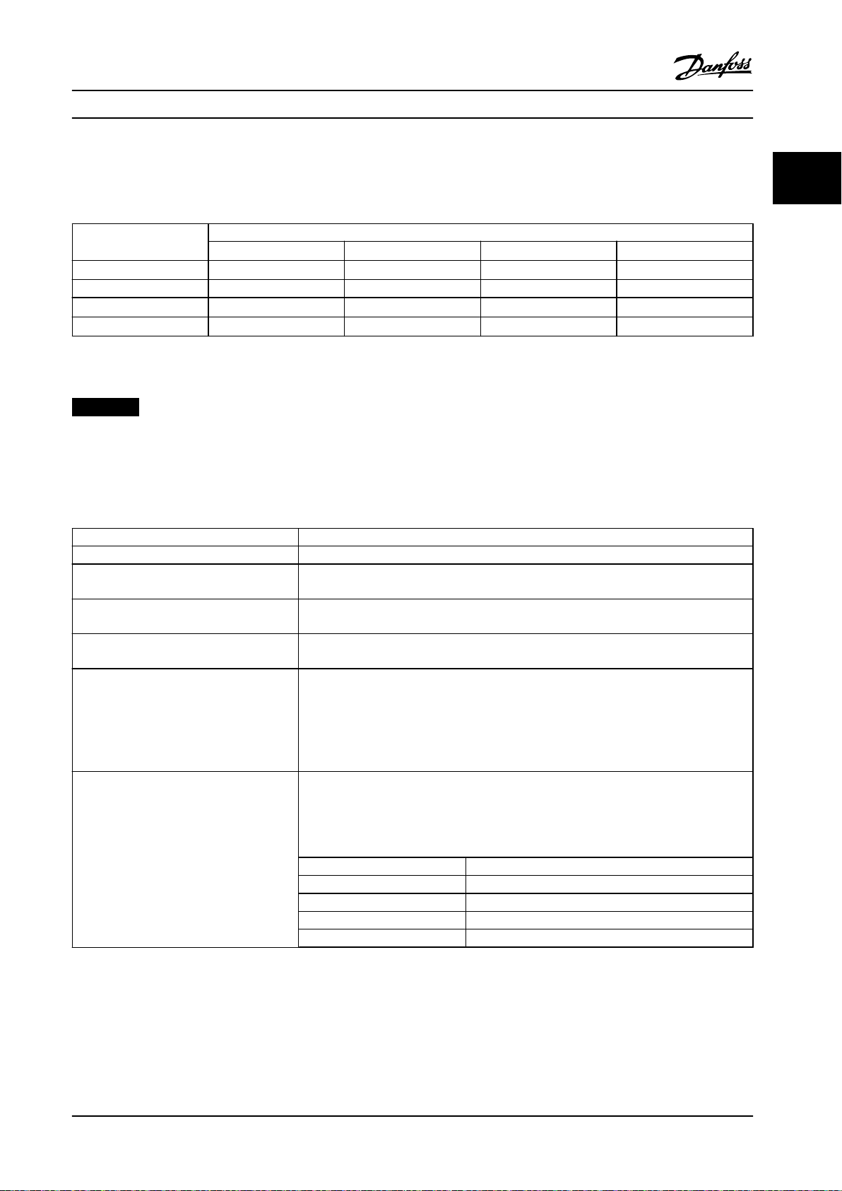
Document and Software Version
1.2
This manual is regularly reviewed and updated. All
suggestions for improvement are welcome. Table 1.1 shows
the document version and the corresponding software
version.
Edition Remarks Software version
MG04H3xx EMC-correct Installation has been
updated.
Table 1.1 Document and Software Version
Denitions
1.3
1.3.1 Frequency Converter
I
VLT,MAX
Maximum output current.
I
VLT,N
Rated output current supplied by the frequency converter.
U
VLT,MAX
Maximum output voltage.
7.5x
6 Danfoss A/S © 05/2018 All rights reserved. MG04H322
Page 9
175ZA078.10
Pull-out
RPM
Torque
Introduction Design Guide
1.3.2 Input
Control command
Start and stop the connected motor with LCP and digital
inputs.
Functions are divided into 2 groups.
Functions in group 1 have higher priority than functions in
group 2.
Group 1 Reset, coast stop, reset and coast stop, quick stop,
DC brake, stop, the [OFF] key.
Group 2 Start, pulse start, reversing, start reversing, jog,
freeze output.
Table 1.2 Function Groups
1.3.3 Motor
U
M,N
Rated motor voltage (nameplate data).
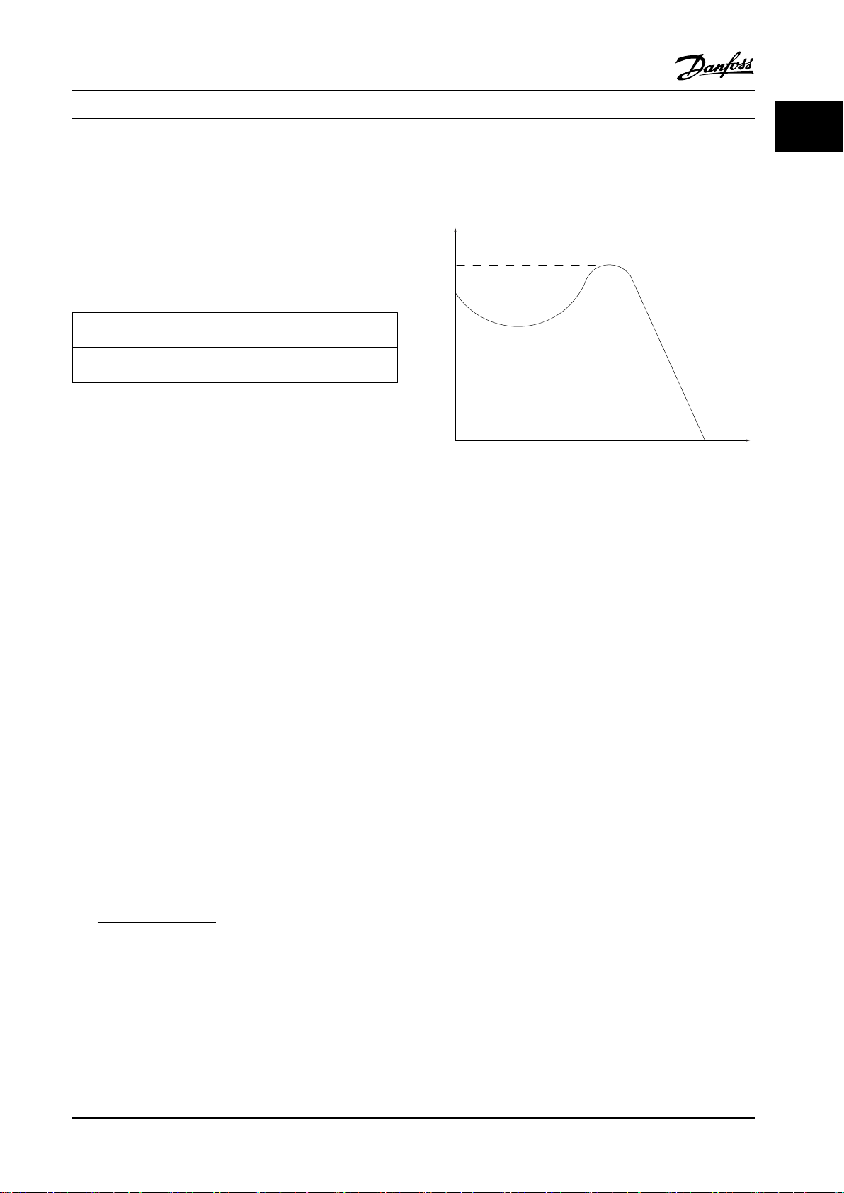
Break-away torque
1 1
Motor running
Torque generated on output shaft and speed from 0 RPM
to maximum speed on motor.
f
JOG
Motor frequency when the jog function is activated (via
digital terminals).
f
M
Motor frequency.
f
MAX
Maximum motor frequency.
f
MIN
Minimum motor frequency.
f
M,N
Rated motor frequency (nameplate data).
I
M
Motor current (actual).
I
M,N
Rated motor current (nameplate data).
n
M,N
Nominal motor speed (nameplate data).
n
s
Synchronous motor speed.
2 × par . 1 − 23 × 60s
ns=
n
slip
par . 1 − 39
Motor slip.
P
M,N
Rated motor power (nameplate data in kW or hp).
T
M,N
Rated torque (motor).
U
M
Instant motor voltage.
Figure 1.1 Break-away Torque
η
VLT
The eciency of the frequency converter is dened as the
ratio between the power output and the power input.
Start-disable command
A stop command belonging to Group 1 control commands
- see Table 1.2.
Stop command
A stop command belonging to Group 1 control commands
- see Table 1.2.
1.3.4 References
Analog reference
A signal transmitted to the analog inputs 53 or 54 (voltage
or current).
Binary reference
A signal transmitted to the serial communication port.
Preset reference
A dened preset reference to be set from -100% to +100%
of the reference range. Selection of 8 preset references via
the digital terminals.
Pulse reference
A pulse frequency signal transmitted to the digital inputs
(terminal 29 or 33).
Ref
MAX
Determines the relationship between the reference input at
100% full scale value (typically 10 V, 20 mA) and the
resulting reference. The maximum reference value is set in
parameter 3-03 Maximum Reference.
MG04H322 Danfoss A/S © 05/2018 All rights reserved. 7
Page 10

Introduction
VLT® Decentral Drive FCD 302
11
Ref
MIN
Determines the relationship between the reference input at
0% value (typically 0 V, 0 mA, 4 mA) and the resulting
reference. The minimum reference value is set in
parameter 3-02 Minimum Reference.
1.3.5 Miscellaneous
Analog inputs
The analog inputs are used for controlling various
functions of the frequency converter.
There are 2 types of analog inputs:
Current input, 0–20 mA, and 4–20 mA
Voltage input, -10 V DC to +10 V DC.
Analog outputs
The analog outputs can supply a signal of 0–20 mA, 4–
20 mA.
Automatic motor adaptation, AMA
AMA algorithm determines the electrical parameters for
the connected motor at standstill.
Brake resistor
The brake resistor is a module capable of absorbing the
brake power generated in regenerative braking. This
regenerative brake power increases the DC-link voltage
and a brake chopper ensures that the power is transmitted
to the brake resistor.
CT characteristics
Constant torque characteristics used for all applications
such as conveyor belts, displacement pumps, and cranes.
Digital inputs
The digital inputs can be used for controlling various
functions of the frequency converter.
Digital outputs
The frequency converter features 2 solid-state outputs that
can supply a 24 V DC (maximum 40 mA) signal.
DSP
Digital signal processor.
ETR
Electronic thermal relay is a thermal load calculation based
on present load and time. Its purpose is to estimate the
motor temperature.
Hiperface
Hiperface® is a registered trademark by Stegmann.
Initializing
If initializing is carried out (parameter 14-22 Operation
Mode), the frequency converter returns to the default
setting.
®
Intermittent duty cycle
An intermittent duty rating refers to a sequence of duty
cycles. Each cycle consists of an on-load and an o-load
period. The operation can be either periodic duty or nonperiodic duty.
LCP
The local control panel makes up a complete interface for
control and programming of the frequency converter. The
control panel is detachable and can be installed up to 3 m
(10 ft) from the frequency converter, that is, in a front
panel with the installation kit option.
lsb
Least signicant bit.
msb
Most signicant bit.
MCM
Short for mille circular mil, an American measuring unit for
cable cross-section. 1 MCM=0.5067 mm2.
Online/oine parameters
Changes to online parameters are activated immediately
after the data value is changed. Press [OK] to activate
changes to o-line parameters.
Process PID
The PID control maintains the required speed, pressure,
temperature, and so on, by adjusting the output frequency
to match the varying load.
PCD
Process control data.
Power cycle
Switch o the mains until display (LCP) is dark, then turn
power on again.
Pulse input/incremental encoder
An external, digital pulse transmitter used for feeding back
information on motor speed. The encoder is used in
applications where great accuracy in speed control is
required.
RCD
Residual current device.
Set-up
Save parameter settings in 4 set-ups. Change between the
4 parameter set-ups and edit 1 set-up, while another setup is active.
SFAVM
Switching pattern called stator ux-oriented asynchronous
vector modulation (parameter 14-00 Switching Pattern).
Slip compensation
The frequency converter compensates for the motor slip by
giving the frequency a supplement that follows the
measured motor load keeping the motor speed almost
constant.
8 Danfoss A/S © 05/2018 All rights reserved. MG04H322
Page 11

Introduction Design Guide
1 1
SLC
The SLC (smart logic control) is a sequence of user-dened
actions executed when the associated user-dened events
are evaluated as true by the SLC. (See chapter 4.9.1 Smart
Logic Controller).
STW
Status word.
FC standard bus
Includes RS485 bus with FC protocol or MC protocol. See
parameter 8-30 Protocol.
THD
Total harmonic distortion states the total contribution of
harmonic.
Thermistor
A temperature-dependent resistor placed on the frequency
converter or the motor.
Trip
A state entered in fault situations, for example if the
frequency converter is subject to an overtemperature or
when the frequency converter is protecting the motor,
process, or mechanism. The frequency converter prevents a
restart until the cause of the fault has disappeared. To
cancel the trip state, restart the frequency converter. Do
not use the trip state for personal safety.
Trip lock
The frequency converter enters this state in fault situations
to protect itself. The frequency converter requires physical
intervention, for example when there is a short circuit on
the output. A trip lock can only be canceled by disconnecting mains, removing the cause of the fault, and
reconnecting the frequency converter. Restart is prevented
until the trip state is canceled by activating reset or,
sometimes, by being programmed to reset automatically.
Do not use the trip lock state for personal safety.
VT characteristics
Variable torque characteristics used for pumps and fans.
+
VVC
If compared with standard voltage/frequency ratio control,
voltage vector control (VVC+) improves the dynamics and
the stability, both when the speed reference is changed
and in relation to the load torque.
60° AVM
60° asynchronous vector modulation
(parameter 14-00 Switching Pattern).
Power factor
The power factor is the relation between I1 and I
Power factor =
3xUxI1cosϕ
3xUxI
RMS
RMS
.
The power factor for 3-phase control:
Power factor =
I1xcosϕ1
I
RMS
=
I
1
sincecosϕ1 = 1
I
RMS
The power factor indicates to which extent the frequency
converter imposes a load on the mains supply.
The lower the power factor, the higher the I
RMS
for the
same kW performance.
I
RMS
=
I
+ I
1
5
+ I
2
+ .. + I
7
2
n
2
2
In addition, a high-power factor indicates that the dierent
harmonic currents are low.
The DC coils in the frequency converters produce a highpower factor, which minimizes the imposed load on the
mains supply.
Target position
The nal target position specied by positioning
commands. The prole generator uses this position to
calculate the speed prole.
Commanded position
The actual position reference calculated by the prole
generator. The frequency converter uses the commanded
position as setpoint for position PI.
Actual position
The actual position from an encoder, or a value that the
motor control calculates in open loop. The frequency
converter uses the actual position as feedback for position
PI.
Position error
Position error is the dierence between the actual position
and the commanded position. The position error is the
input for the position PI controller.
Position unit
The physical unit for position values.
MG04H322 Danfoss A/S © 05/2018 All rights reserved. 9
Page 12
Introduction
VLT® Decentral Drive FCD 302
11
1.4 Safety Precautions
WARNING
The voltage of the frequency converter is dangerous
whenever connected to mains. Correct planning of the
installation of the motor, frequency converter, and
eldbus are necessary. Follow the instructions in this
manual, and the national and local rules and safety
regulations. Failure to follow design recommendations
could result in death, serious personal injury, or damage
to the equipment once in operation.
WARNING
HIGH VOLTAGE
Touching the electrical parts may be fatal - even after
the equipment has been disconnected from mains.
In planning, ensure that other voltage inputs can be
disconnected, such as external 24 V DC, load sharing
(linkage of DC intermediate circuit), and the motor
connection for kinetic back-up.
Systems where frequency converters are installed must, if
necessary, be equipped with additional monitoring and
protective devices according to the valid safety
regulations, for example law on mechanical tools,
regulations for the prevention of accidents, and so on.
Modications on the frequency converters by means of
the operating software are allowed.
Failure to follow design recommendations, could result in
death or serious injury once the equipment is in
operation.
NOTICE!
Hazardous situations have to be identied by the
machine builder/integrator who is responsible for taking
necessary preventive means into consideration.
Additional monitoring and protective devices may be
included, always according to valid national safety
regulations, for example, law on mechanical tools,
regulations for the prevention of accidents.
NOTICE!
Crane, lifts, and hoists:
The controlling of external brakes must always be
designed with a redundant system. The frequency
converter can in no circumstances be the primary safety
circuit. Comply with relevant standards, for example.
Hoists and cranes: IEC 60204-32
Lifts: EN 81
Protection mode
Once a hardware limit on motor current or DC-link voltage
is exceeded, the frequency converter enters protection
mode. Protection mode means a change of the PWM
modulation strategy and a low switching frequency to
minimize losses. This continues 10 s after the last fault and
increases the reliability and the robustness of the
frequency converter while re-establishing full control of the
motor.
In hoist applications, protection mode is not usable
because the frequency converter is usually unable to leave
this mode again and therefore it extends the time before
activating the brake – which is not recommended.
The protection mode can be disabled by setting
parameter 14-26 Trip Delay at Inverter Fault to 0 which
means that the frequency converter trips immediately if 1
of the hardware limits is exceeded.
NOTICE!
Disable protection mode in hoisting applications
(parameter 14-26 Trip Delay at Inverter Fault=0).
WARNING
DISCHARGE TIME
The frequency converter contains DC-link capacitors,
which can remain charged even when the frequency
converter is not powered. High voltage can be present
even when the warning LED indicator lights are o.
Failure to wait the specied time after power has been
removed before performing service or repair work can
result in death or serious injury.
Stop the motor.
•
Disconnect AC mains and remote DC-link power
•
supplies, including battery back-ups, UPS, and
DC-link connections to other frequency
converters.
Disconnect or lock PM motor.
•
Wait for the capacitors to discharge fully. The
•
minimum waiting time is specied in Table 1.3
and is also visible on the product label on top
of the frequency converter.
Before performing any service or repair work,
•
use an appropriate voltage measuring device to
make sure that the capacitors are fully
discharged.
10 Danfoss A/S © 05/2018 All rights reserved. MG04H322
Page 13

Introduction Design Guide
1 1
Voltage [V] Minimum waiting time (minutes)
4 7 15
200–240 0.25–3.7 kW
(0.34–5 hp)
380–500 0.25–7.5 kW
(0.34–10 hp)
525–600 0.75–7.5 kW
(1–10 hp)
525–690 – 1.5–7.5 kW
Table 1.3 Discharge Time
– 5.5–37 kW
(7.5–50 hp)
– 11–75 kW
(15–100 hp)
– 11–75 kW
(15–100 hp)
(2–10 hp)
(15–100 hp)
11–75 kW
1.5 CE Labeling
CE labeling is a positive feature when used for its original
purpose, that is, to facilitate trade within the EU and EFTA.
However, CE labeling may cover many
cations. Check what a given CE label specically covers.
The specications can vary greatly. A CE label may
therefore give the installer a false sense of security when
using a frequency converter as a component in a system
or an appliance.
Danfoss CE labels the frequency converters in accordance
with the Low Voltage Directive. This means that if the
frequency converter is installed correctly, compliance with
the Low Voltage Directive is achieved. Danfoss issues a
declaration of conformity that conrms CE labeling in
accordance with the Low Voltage Directive.
The CE label also applies to the EMC directive, if the
instructions for EMC-correct installation and
followed. On this basis, a declaration of conformity in
accordance with the EMC directive is issued.
dierent speci-
ltering are
What is CE conformity and labeling?
The purpose of CE labeling is to avoid technical trade
obstacles within EFTA and the EU. The EU has introduced
the CE label as a simple way of showing whether a
product complies with the relevant EU directives. The CE
label says nothing about the specications or quality of
the product. Frequency converters are regulated by 2 EU
directives:
The Low Voltage Directive (2014/35/EU)
Frequency converters must be CE-labeled in accordance
with the Low Voltage Directive of January 1, 2014. The Low
Voltage Directive applies to all electrical equipment in the
50–1000 V AC and the 75–1500 V DC voltage ranges.
The aim of the directive is to ensure personal safety and
avoid property damage when operating electrical
equipment that is installed, maintained, and used as
intended.
The EMC Directive (2014/30/EU)
The purpose of the EMC (electromagnetic compatibility)
Directive is to reduce electromagnetic interference and
enhance immunity of electrical equipment and installations. The basic protection requirement of the EMC
Directive is that devices that generate electromagnetic
interference (EMI), or whose operation could be aected
by EMI, must be designed to limit the generation of
electromagnetic interference. The devices must have a
suitable degree of immunity to EMI when properly
installed, maintained, and used as intended.
Electrical equipment devices used alone or as part of a
system must bear the CE mark. Systems do not require the
CE mark, but must comply with the basic protection
requirements of the EMC Directive.
The frequency converter is most often used by professionals of the trade as a complex component forming part
of a larger appliance, system, or installation.
The design guide oers detailed instructions for installation
to ensure EMC-correct installation.
1.5.1 Conformity
The Machinery Directive (2006/42/EC)
Frequency converters do not fall under the machinery
directive. However, if a frequency converter is supplied for
use in a machine, Danfoss provides information on safety
aspects relating to the frequency converter.
MG04H322 Danfoss A/S © 05/2018 All rights reserved. 11
Page 14
Introduction
VLT® Decentral Drive FCD 302
11
1.5.2 What Is Covered?
The EU EMC Directive 2014/30/EU outline 3 typical
situations of using a frequency converter. See below for
EMC coverage and CE labeling.
The frequency converter is sold directly to the
•
end user. The frequency converter is for example
sold to a do-it-yourself market. The end user is a
layman, installing the frequency converter for use
with a hobby machine, a kitchen appliance, and
so on. For such applications, the frequency
converter must be CE labeled in accordance with
the EMC directive.
The frequency converter is sold for installation in
•
a plant. The plant is built up by professionals of
the trade. It could be a production plant or a
heating/ventilation plant designed and installed
by professionals of the trade. The frequency
converter and the nished plant do not have to
be CE labeled under the EMC directive. However,
the unit must comply with the basic EMC
requirements of the directive. This is ensured by
using components, appliances, and systems that
are CE labeled under the EMC directive.
The frequency converter is sold as part of a
•
complete system. The system is marketed as
complete, for example an air-conditioning system.
The complete system must be CE labeled in
accordance with the EMC directive. The
manufacturer can ensure CE labeling under the
EMC directive either by using CE labeled
components or by testing the EMC of the system.
If only CE labeled components are used, it is
unnecessary to test the entire system.
Approvals
1.7
Table 1.4 FCD 302 Approvals
The frequency converter complies with UL 508C thermal
memory retention requirements. For more information,
refer to chapter 3.4.3.2 Motor Thermal Protection.
1.8 Disposal
Equipment containing electrical
components may not be disposed of
together with domestic waste.
It must be separately collected with
electrical and electronic waste according
to local and currently valid legislation.
Table 1.5 Disposal Instruction
Compliance with EMC Directive
1.6
2004/1087EC
The frequency converter is mostly used by professionals of
the trade as a complex component forming part of a larger
appliance, system, or installation.
NOTICE!
The responsibility for the nal EMC properties of the
appliance, system, or installation rests with the installer.
As an aid to the installer, Danfoss has prepared EMC installation guidelines for the power drive system. The standards
and test levels stated for power drive systems are complied
with, if the EMC-correct instructions for installation are
followed, see chapter 2.9.4 EMC.
12 Danfoss A/S © 05/2018 All rights reserved. MG04H322
Page 15
130BC963.10
130BC964.10
130BC968.11
1325 4
6
9
8
M
7
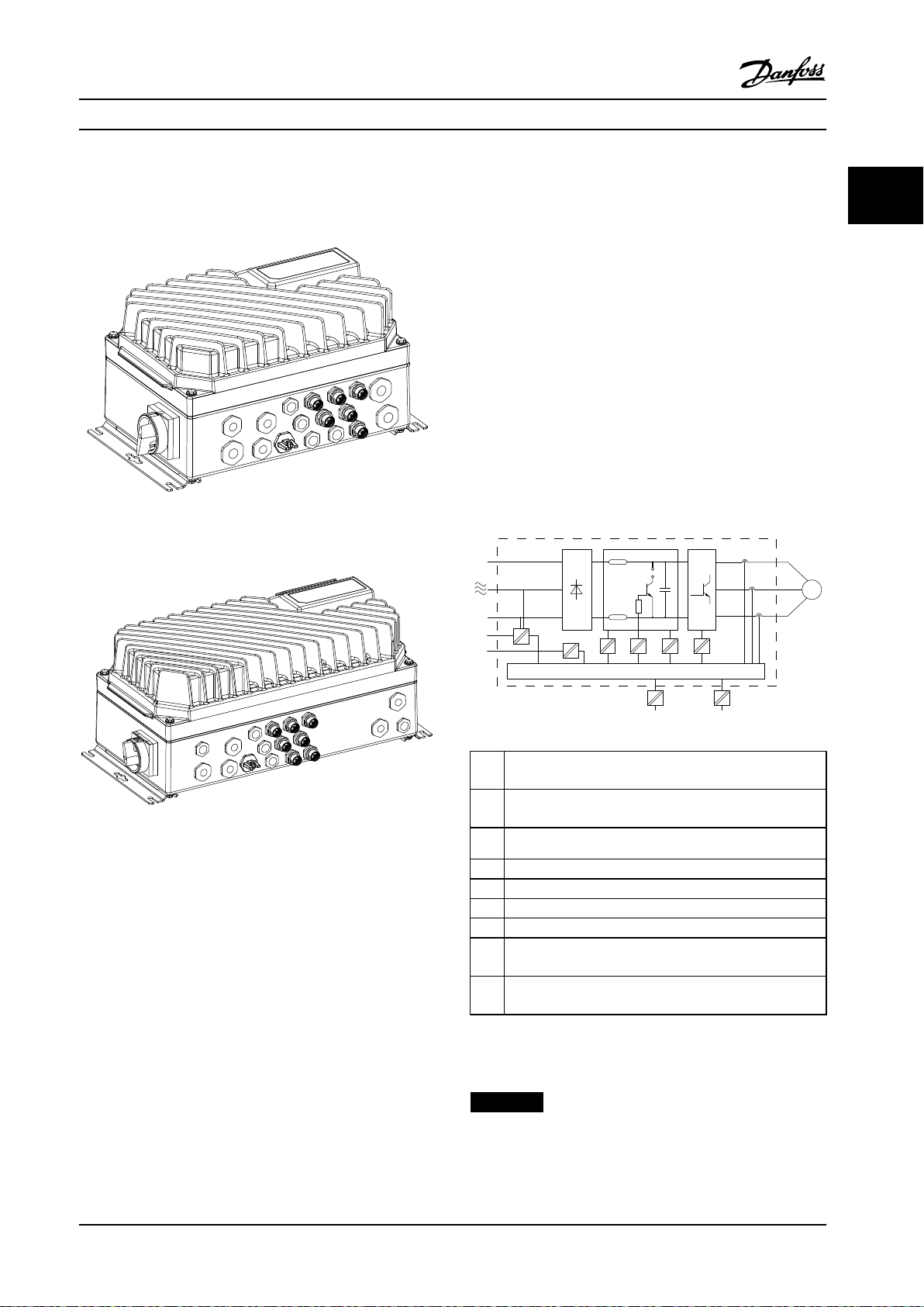
Product Overview and Functi... Design Guide
2 Product Overview and Functions
Figure 2.1 Small Unit
2 2
relevant creepage/clearance distances. These requirements
are described in the EN 61800-5-1 standard.
The components that make up the electrical isolation, as
described in Figure 2.3, also comply with the requirements
for higher isolation and the relevant test as described in
EN 61800-5-1.
The PELV galvanic isolation can be shown in 6 locations
(see Figure 2.3).
To maintain PELV, all connections made to the control
terminals must be PELV, for example, thermistor must be
reinforced/double insulated.
1 Power supply (SMPS) including signal isolation of UDC,
indicating the voltage of intermediate DC Link circuit.
2 Gate drive that runs the IGBTs (trigger transformers/opto-
Figure 2.2 Large Unit
2.1 Galvanic Isolation (PELV)
2.1.1 PELV - Protective Extra Low Voltage
PELV oers protection by way of extra low voltage.
Protection against electric shock is ensured when the
electrical supply is of the PELV type and the installation is
couplers).
3 Current transducers.
4 Opto-coupler, brake module.
5 Internal inrush, RFI, and temperature measurement circuits.
6 Custom relays.
7 Mechanical brake.
8 Functional galvanic isolation for the 24 V back-up option
and for the RS485 standard bus interface.
9 Functional galvanic isolation for the 24 V back-up option
and for the RS485 standard bus interface.
made as described in local/national regulations on PELV
supplies.
Figure 2.3 Galvanic Isolation
All control terminals and relay terminals 01–03/04–06
comply with PELV (protective extra low voltage), except for
grounded delta leg above 400 V.
Galvanic (ensured) isolation is obtained by fullling
NOTICE!
Installation at high altitude:
380–500 V: At altitudes above 2000 m (6561 ft), contact
Danfoss regarding PELV.
requirements for higher isolation and by providing the
MG04H322 Danfoss A/S © 05/2018 All rights reserved. 13
Page 16
130BB957.11
Leakage current [mA]
100 Hz
2 kHz
100 kHz
Product Overview and Functi...
VLT® Decentral Drive FCD 302
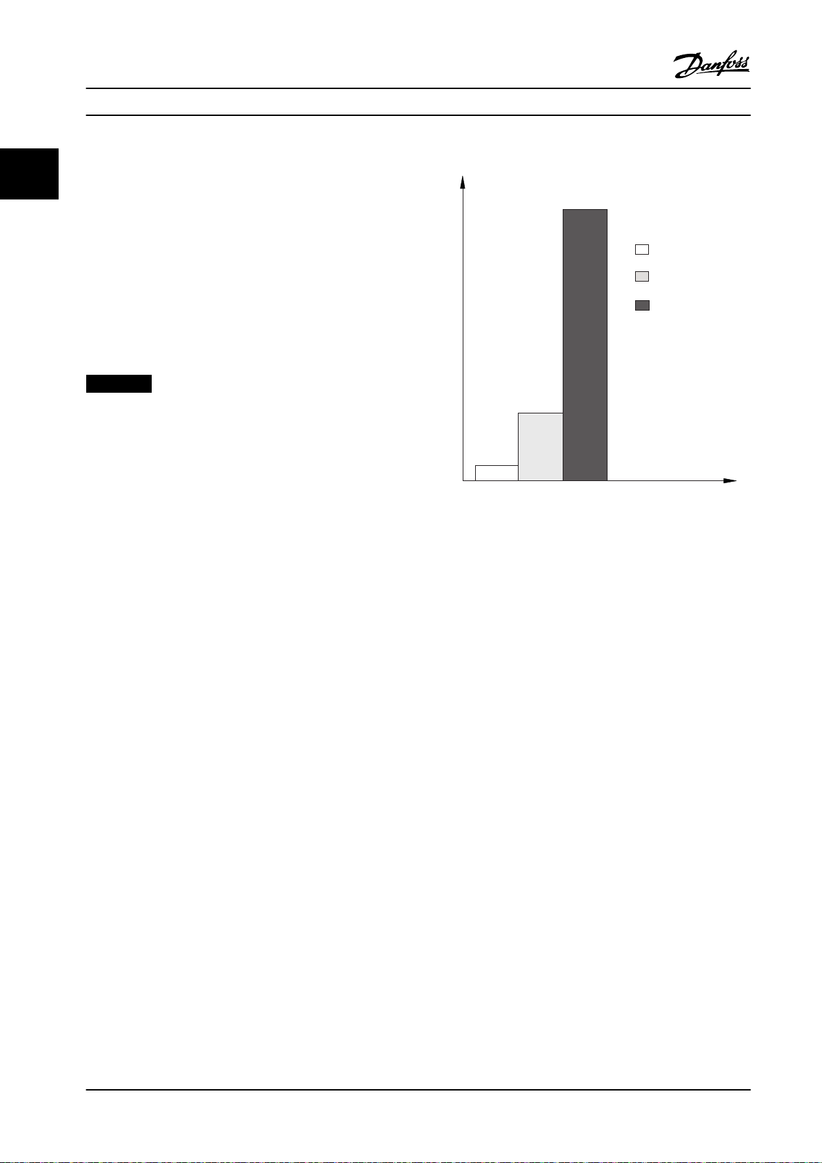
2.1.2 Ground Leakage Current
22
Follow national and local codes regarding protective
grounding of equipment with a leakage current >3.5 mA.
Frequency converter technology implies high frequency
switching at high power. This generates a leakage current
in the ground connection. A fault current in the frequency
converter at the output power terminals might contain a
DC component which can charge the lter capacitors and
cause a transient ground current.
The leakage current also depends on the line distortion.
NOTICE!
When a lter is used, turn o parameter 14-50 RFI Filter
when charging the lter, to avoid that a high leakage
current makes the RCD switch.
EN/IEC61800-5-1 (power drive system product standard)
requires special care if the leakage current exceeds 3.5 mA.
Grounding must be reinforced in 1 of the following ways:
Figure 2.4 Inuence of Cut-o Frequency of the RCD
Ground wire (terminal 95) of at least 10 mm
•
(7 AWG). This requires a PE adapter (available as
an option).
Two separate ground wires both complying with
•
the dimensioning rules.
See EN/IEC61800-5-1 and EN 50178 for further information.
Using RCDs
Where residual current devices (RCDs), also known as
ground leakage circuit breakers (CLCBs), are used, comply
with the following:
Use RCDs of type B, which are capable of
•
detecting AC and DC currents.
Use RCDs with an inrush delay to prevent faults
•
due to transient ground currents.
Dimension RCDs according to the system
•
ration and environmental considerations.
2
congu-
See also RCD Application Note.
Control
2.2
A frequency converter recties AC voltage from mains into
DC voltage. This DC voltage is converted into an AC
current with a variable amplitude and frequency.
The motor is supplied with variable voltage, current, and
frequency, which enables innitely variable speed control
of 3-phased, standard AC motors and permanent magnet
synchronous motors.
The VLT® Decentral Drive FCD 302 frequency converter is
designed for installations of multiple smaller frequency
converters, especially on conveyor applications, for
example, in the food and beverage industries and materials
handling. In installations where multiple motors are spread
around a facility such as bottling plants, food preparation,
packaging plants, and airport baggage handling installations, there may be dozens, perhaps hundreds, of
frequency converters, working together but spread over a
large physical area. In these cases, cabling costs alone
outweigh the cost of the individual frequency converters
and it makes sense to get the control closer to the motors.
The frequency converter can control either the speed or
the torque on the motor shaft.
14 Danfoss A/S © 05/2018 All rights reserved. MG04H322
Page 17
R+
82
R81
Brake
Resistor
U 96
V 97
W 98
InrushR inr
P 14-50
L1 91
L2 92
L3 93
M
130BC965.10
Product Overview and Functi... Design Guide
Speed control
Two types of speed control:
Speed open-loop control, which does not require
•
any feedback from the motor (sensorless).
Speed closed-loop PID control, which requires a
•
speed feedback to an input. A properly optimized
speed closed-loop control is more accurate than a
speed open-loop control.
Torque control
The torque control function is used in applications where
the torque on motor output shaft controls the application
as tension control.
Closed loop in ux mode with encoder feedback
•
comprises motor control based on feedback
signals from the system. It improves performance
in all 4 quadrants and at all motor speeds.
Open loop in VVC+ mode. The function is used in
•
mechanical robust applications, but the accuracy
is limited. Open-loop torque function works only
in 1 speed direction. The torque is calculated on
basis of current measurement internal in the
frequency converter. See application example
chapter 2.3.1 Control Structure in VVC+ Advanced
Vector Control.
Speed/torque reference
The reference to these controls can either be a single
reference or be the sum of various references including
relatively scaled references. The handling of references is
explained in detail in chapter 2.6 Handling of Reference.
2 2
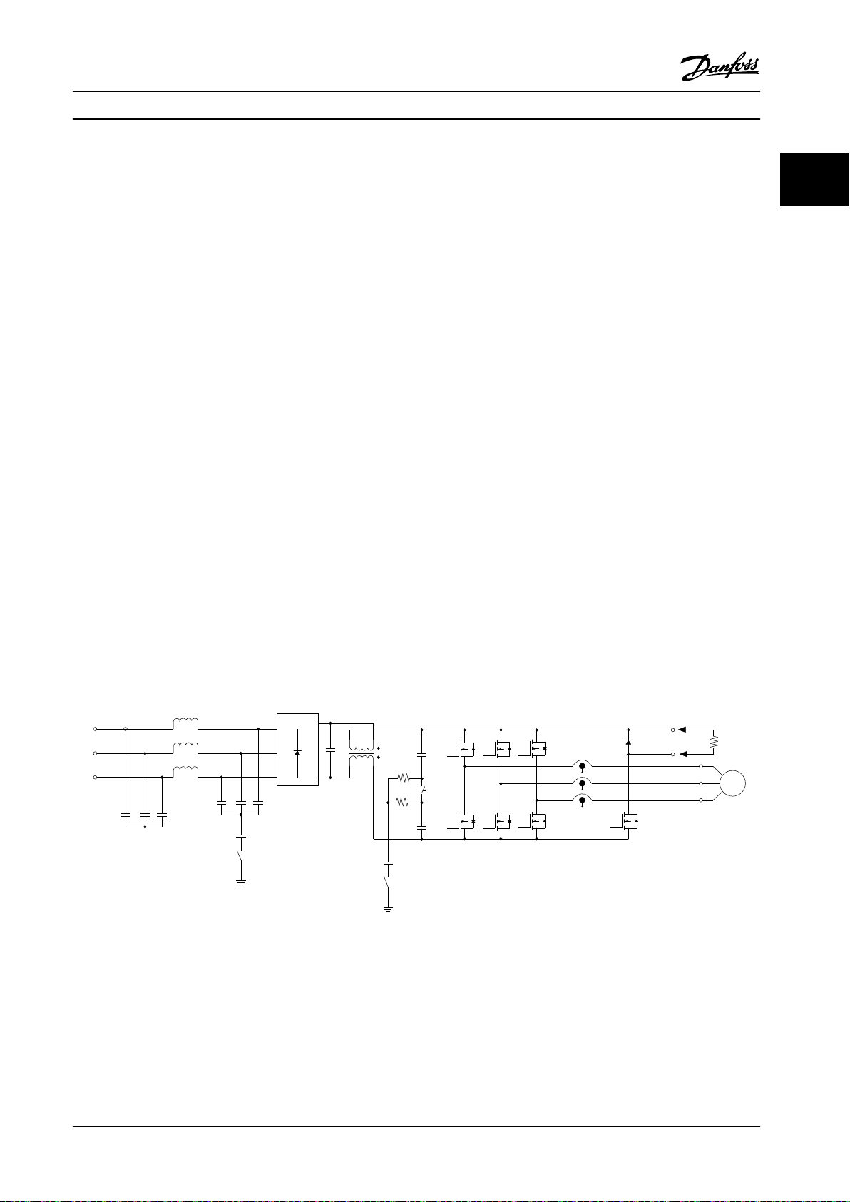
2.2.1 Control Principle
The frequency converter is compatible with various motor control principles such as U/f special motor mode, VVC+, or ux
vector motor control.
In addition, the frequency converter is operable with permanent magnet synchronous motors (brushless servo motors) and
normal squirrel lift cabin asynchronous motors.
The short circuit behavior depends on the 3 current transducers in the motor phases and the desaturation protection with
feedback from the brake.
Figure 2.5 Control Principle
MG04H322 Danfoss A/S © 05/2018 All rights reserved. 15
Page 18

+
_
+
_
Cong. mode
Ref.
Process
P 1-00
High
+f max.
Low
-f max.
P 4-11
Motor speed
low limit (RPM)
P 4-12
Motor speed
low limit (Hz)
P 4-13
Motor speed
high limit (RPM)
P 4-14
Motor speed
high limit (Hz)
Motor
controller
Ramp
Speed
PID
P 7-20 Process feedback
1 source
P 7-22 Process feedback
2 source
P 7-00 Speed PID
feedback source
P 1-00
Cong. mode
P 4-19
Max. output freq.
-f max.
Motor
controller
P 4-19
Max. output freq.
+f max.
P 3-**
P 7-0*
130BA055.10
Product Overview and Functi...
2.2.2
Internal Current Control in VVC+ Mode
VLT® Decentral Drive FCD 302
22
The frequency converter features an integral current limit control which is activated when the motor current, and thus the
torque, is higher than the torque limits set in parameter 4-16 Torque Limit Motor Mode, parameter 4-17 Torque Limit Generator
Mode, and parameter 4-18 Current Limit.
When the frequency converter is at the current limit during motor operation or regenerative operation, it reduces torque to
below the preset torque limits as quickly as possible without losing control of the motor.
2.3 Control Structures
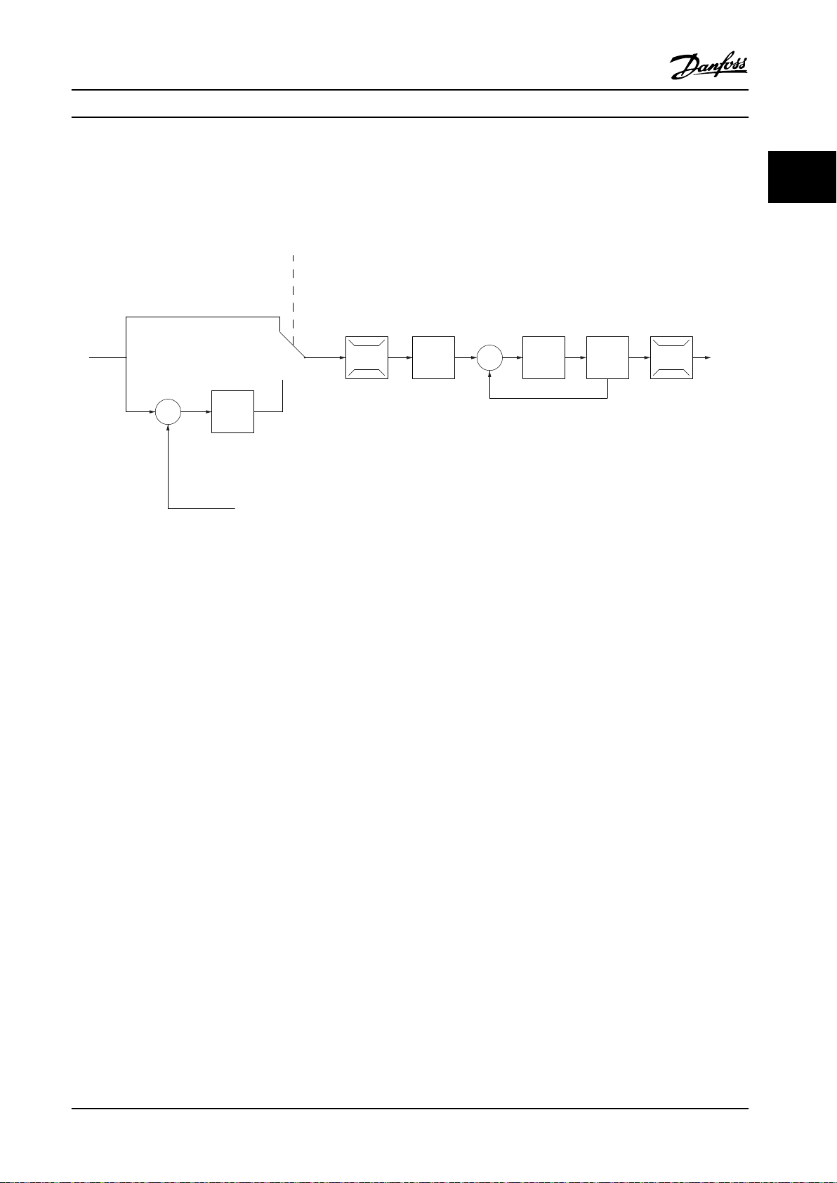
2.3.1
Control Structure in VVC+ Advanced Vector Control
Figure 2.6 Control Structure in VVC+ Open-loop and Closed-loop Congurations
In the conguration shown in Figure 2.6, parameter 1-01 Motor Control Principle is set to [1] VVC+ and parameter 1-00 Congu-
ration Mode is set to [0] Speed open loop. The resulting reference from the reference handling system is received and fed
through the ramp limitation and speed limitation before being sent to the motor control. The output of the motor control is
then limited by the maximum frequency limit.
If parameter 1-00
and speed limitation into a speed PID control. The speed PID control parameters are in the parameter group 7-0* Speed PID
Ctrl. The resulting reference from the speed PID control is sent to the motor control limited by the frequency limit.
Select [3] Process in parameter 1-00 Conguration Mode to use the process PID control for closed-loop control of, for example,
speed or pressure in the controlled application. The process PID parameters are in parameter group 7-2* Process Ctrl. Feedb
and parameter group 7-3* Process PID Ctrl.
16 Danfoss A/S © 05/2018 All rights reserved. MG04H322
Conguration Mode is set to [1] Speed closed loop, the resulting reference passes from the ramp limitation
Page 19
+
_
+
_
130BA053.11
Ref.
Cong. mode
P 1-00
P 7-20 Process feedback
1 source
P 7-22 Process feedback
2 source
Process
PID
P 4-11 Motor speed
low limit [RPM]
P 4-12 Motor speed
low limit [Hz]
P 4-14 Motor speed
high limit [Hz]
P 4-13 Motor speed
high limit [RPM]
Low
High
Ramp
P 3-**
+f max.
P 4-19
Max. output
freq.
Motor
controller
-f max.
Speed
PID
P 7-0*
Product Overview and Functi... Design Guide
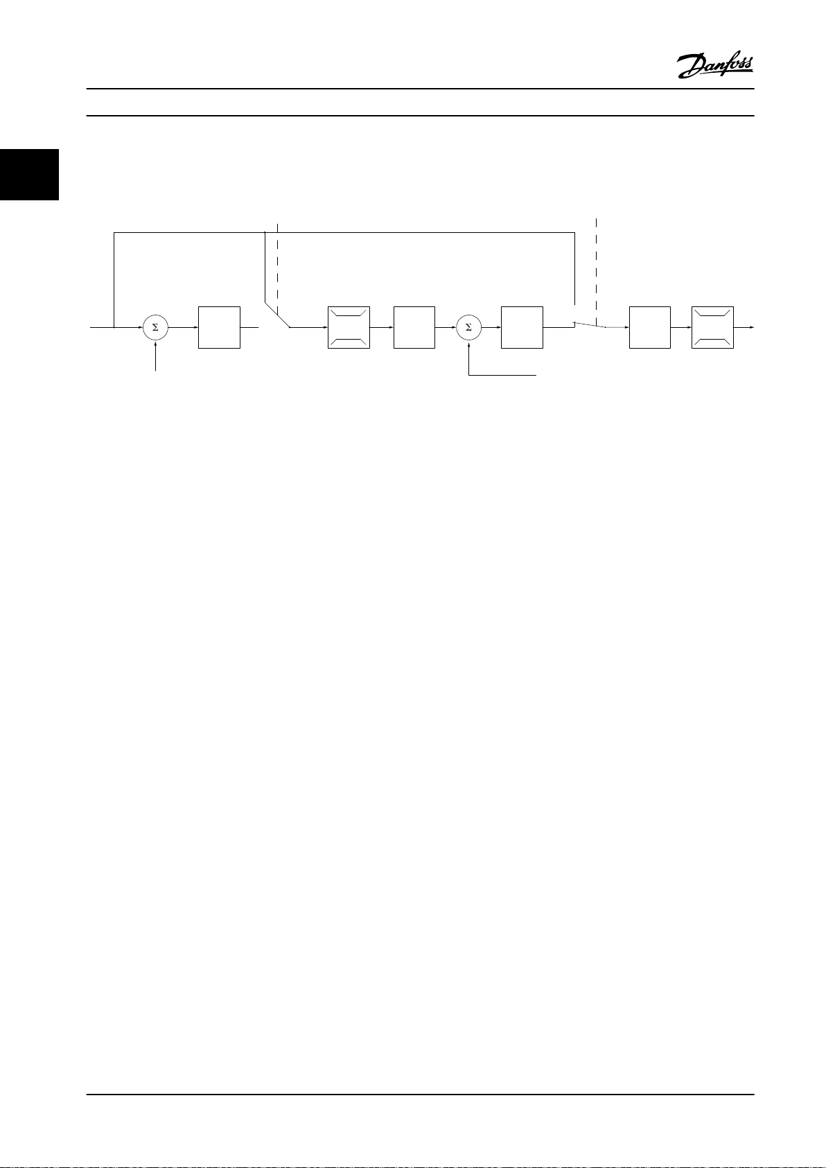
2.3.2 Control Structure in Flux Sensorless
Control structure in ux sensorless open-loop and closed-loop congurations.
2 2
Figure 2.7 Control Structure in Flux Sensorless
In the conguration shown, parameter 1-01 Motor Control Principle is set to [2] Flux Sensorless and parameter 1-00 Congu-
ration Mode is set to [0] Speed open loop. The resulting reference from the reference handling system is fed through the
ramp and speed limitations as determined by the parameter settings indicated.
An estimated speed feedback is generated to the speed PID to control the output frequency.
The speed PID must be set with its P, I, and D parameters (parameter group 7-0* Speed PID Ctrl.).
Select [3] Process in parameter 1-00 Conguration Mode to use the process PID control for closed-loop control of speed or
pressure in the controlled application. The process PID parameters are in parameter group 7-2* Process Ctrl. Feedb. and
parameter group7-3* Process PID Ctrl.
MG04H322 Danfoss A/S © 05/2018 All rights reserved. 17
Page 20
130BA054.11
P 3-** P 7-0*P 7-2*
+
_
+
_
P 7-20 Process feedback
1 source
P 7-22 Process feedback
2 source
P 4-11 Motor speed
low limit (RPM)
P 4-12 Motor speed
low limit (Hz)
P 4-13 Motor speed
high limit (RPM)
P 4-14 Motor speed
high limit (Hz)
High
Low
Ref.
Process
PID
Speed
PID
Ramp
P 7-00
PID source
Motor
controller
-f max.
+f max.
P 4-19
Max. output
freq.
P 1-00
Cong. mode
P 1-00
Cong. mode
Torque
Product Overview and Functi...
VLT® Decentral Drive FCD 302
2.3.3 Control Structure in Flux with Motor Feedback
22
Figure 2.8 Control Structure in Flux with Motor Feedback
In the conguration shown, parameter 1-01 Motor Control Principle is set to [3] Flux w motor feedb and parameter 1-00 Cong-
uration Mode is set to [1] Speed closed loop.
The motor control in this conguration relies on a feedback signal from an encoder mounted directly on the motor (set in
parameter 1-02 Flux Motor Feedback Source).
Select [1] Speed closed loop in parameter 1-00 Conguration Mode to use the resulting reference as an input for the speed
PID control. The speed PID control parameters are located in parameter group 7-0* Speed PID Ctrl.
Select [2] Torque in parameter 1-00 Conguration Mode to use the resulting reference directly as a torque reference. Torque
control can only be selected in the [3] Flux with motor feedback (parameter 1-01 Motor Control Principle) conguration. When
this mode has been selected, the reference uses the Nm unit. It requires no torque feedback, since the actual torque is
calculated based on the current measurement of the frequency converter.
Select [3] Process in parameter 1-00
Conguration Mode to use the process PID control for closed-loop control of a process
variable (for example, speed) in the controlled application.
18 Danfoss A/S © 05/2018 All rights reserved. MG04H322
Page 21
130BP046.10
Hand
on
O
Auto
on
Reset
Remote
reference
Local
reference
(Auto On)
(Hand On)
Linked to hand/auto
Local
Remote
Reference
130BA245.12
LCP keys:
(Hand On), (O),
and (Auto On)
P 3-13 Reference Site
Product Overview and Functi... Design Guide
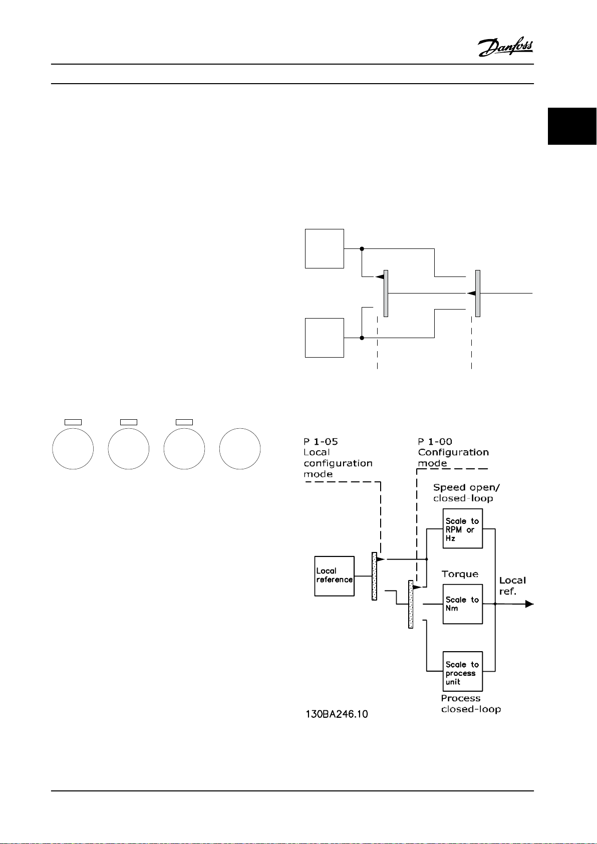
2.3.4 Local [Hand On] and Remote [Auto
On] Control
The frequency converter can be operated manually via the
local control panel (LCP) or remotely via analog and digital
inputs and eldbus. If allowed in parameter 0-40 [Hand on]
Key on LCP, parameter 0-41 [O] Key on LCP,
parameter 0-42 [Auto on] Key on LCP, and
parameter 0-43 [Reset] Key on LCP, it is possible to start and
stop the frequency converter via the LCP using the [Hand
On] and [O] keys. Alarms can be reset via the [Reset] key.
After pressing the [Hand On] key, the frequency converter
goes into hand-on mode and follows (as default) the local
reference that can be set using the navigation keys on the
LCP.
After pressing the [Auto On] key, the frequency converter
goes into auto-on mode and follows (as default) the
remote reference. In this mode, it is possible to control the
frequency converter via the digital inputs and various serial
interfaces (RS485, USB, or an optional
about starting, stopping, changing ramps, parameter setups, and so on, in parameter group 5-1* Digital Inputs or
parameter group 8-5* Digital/Bus.
eldbus). See more
Active reference and conguration mode
The active reference can be either the local reference or
the remote reference.
In parameter 3-13 Reference Site, the local reference can be
permanently selected by selecting [2] Local.
For permanent setting of the remote reference, select [1]
Remote. By selecting [0] Linked to Hand/Auto (default), the
reference site links to the active mode (hand-on mode or
auto-on Mode).
Figure 2.10 Local Handling of Reference
2 2
Figure 2.9 LCP Keys
Figure 2.11 Remote Handling of Reference
MG04H322 Danfoss A/S © 05/2018 All rights reserved. 19
Page 22
130BC997.10
P 5-40 [0] [32]
-
+
01 02 03
24 VDC
I max
0.1 Amp
2 3
1
Product Overview and Functi...
VLT® Decentral Drive FCD 302
LCP keys Parameter 3-13 Reference Site Active reference
22
Hand Linked to Hand/Auto Local
Hand⇒O
Auto Linked to Hand/Auto Remote
Auto⇒O Linked to Hand/Auto Remote
All keys Local Local
All keys Remote Remote
Table 2.1 Conditions for Local/Remote Handling of Reference
Parameter 1-00
Linked to Hand/Auto Local
Conguration Mode determines what type
Parameter 5-02 Terminal 29 Mode [1] Terminal 29
Mode Output
Parameter 5-31 Terminal 29 digital Output [27]
Torque Limit & Stop
[0] Relay output (relay 1)
•
Parameter 5-40 Function Relay [32] Mechanical
Brake Control
of application control principle (that is, speed, torque, or
process control) is used when the remote reference is
active. Parameter 1-05 Local Mode Conguration determines
the type of application control principle that is used when
the local reference is active. One of them is always active,
but both cannot be active at the same time.
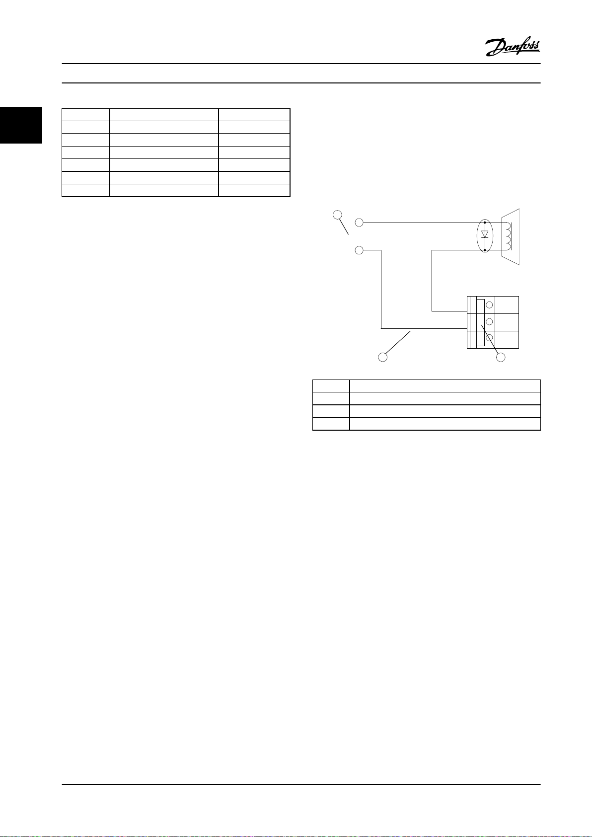
2.3.5 Programming of Torque Limit and
Stop
In applications with an external electro-mechanical brake,
such as hoisting applications, it is possible to stop the
frequency converter via a standard stop command and
simultaneously activate the external electro-mechanical
brake.
The example given below, illustrates the programming of
the frequency converter connections.
The external brake can be connected to relay 1 or 2.
Program parameter 5-01 Terminal 27 Mode to [2] Coast,
inverse or [3] Coast and Reset, inverse, and program
parameter 5-02 Terminal 29 Mode to [1] Output and [27]
Torque limit & stop.
Item Description
1 External 24 V DC
2 Mechanical brake connection
3 Relay 1
Figure 2.12 Mechanical Brake Control
Description
If a stop command is active via terminal 18, and the
frequency converter is not at the torque limit, the motor
ramps down to 0 Hz.
If the frequency converter is at the torque limit and a stop
command is activated, parameter 5-31 Terminal 29 digital
Output (programmed to [27] torque limit and stop) is
activated. The signal to terminal 27 changes from logic 1
to logic 0, and the motor starts to coast. The coast ensures
that the hoist stops even if the frequency converter itself
cannot handle the required torque (that is, due to
excessive overload).
Start/stop via terminal 18
•
•
•
20 Danfoss A/S © 05/2018 All rights reserved. MG04H322
Parameter 5-10 Terminal 18 Digital Input [8] Start
Quick stop via terminal 27
Parameter 5-12 Terminal 27 Digital Input [2] Coast
Stop, inverse
Terminal 29 output
Page 23
Product Overview and Functi... Design Guide
2.4 PID Control
2.4.1 Speed PID Control
2 2
Parameter 1-00 Congu-
ration Mode
[0] Speed open loop
[1] Speed closed loop – Active – Active
[2] Torque – – –
[3] Process –
Table 2.2 Control Congurations where the Speed Control is Active
1) “Not active” means that the specic mode is available, but the speed control is not active in that mode.
Parameter 1-01 Motor Control Principle
U/f
Not active
1)
+
VVC
Not active
Not active
Flux sensorless Flux w/ encoder feedback
1)
1)
Active –
Not active
Active Active
1)
NOTICE!
The speed PID control works under the default parameter setting, but tuning the parameters is highly recommended to
optimize the motor control performance. The 2 ux motor control principles are particularly dependent on proper
tuning to yield their full potential.
2.4.2 Parameters Relevant for Speed Control
Parameter Description of function
Parameter 7-00 Speed PID Feedback Source Select from which input the speed PID should get its feedback.
Parameter 30-83 Speed PID Proportional Gain The higher the value - the quicker the control. However, too high value may lead to
oscillations.
Parameter 7-03 Speed PID Integral Time Eliminates steady state speed error. Lower value means quick reaction. However, too low
value may lead to oscillations.
Parameter 7-04 Speed PID Dierentiation Time Provides a gain proportional to the rate of change of the feedback. A setting of 0 disables
the dierentiator.
Parameter 7-05 Speed PID Di. Gain Limit If there are quick changes in reference or feedback in a given application, which means
that the error changes swiftly, the dierentiator may soon become too dominant. This is
because it reacts to changes in the error. The quicker the error changes, the stronger the
dierentiator gain is. The dierentiator gain can thus be limited to allow setting of the
reasonable dierentiation time for slow changes and a suitably quick gain for quick
changes.
Parameter 7-06 Speed PID Lowpass Filter Time A low-pass lter that dampens oscillations on the feedback signal and improves steady
state performance. However, too large lter time deteriorates the dynamic performance of
the speed PID control.
Practical settings of parameter 7-06 Speed PID Lowpass Filter Time taken from the number of
pulses per revolution from encoder (PPR):
Encoder PPR Parameter 7-06 Speed PID Lowpass Filter Time
512 10 ms
1024 5 ms
2048 2 ms
4096 1 ms
Table 2.3 Parameters Relevant for Speed Control
MG04H322 Danfoss A/S © 05/2018 All rights reserved. 21
Page 24
M
3
96 97 9998
91 92 93 95
50
12
L1 L2L1PEL3
W PEVU
F1
L2
L3
N
PE
18
53
37
55
20
32
33
39
24 Vdc
130BA174.10
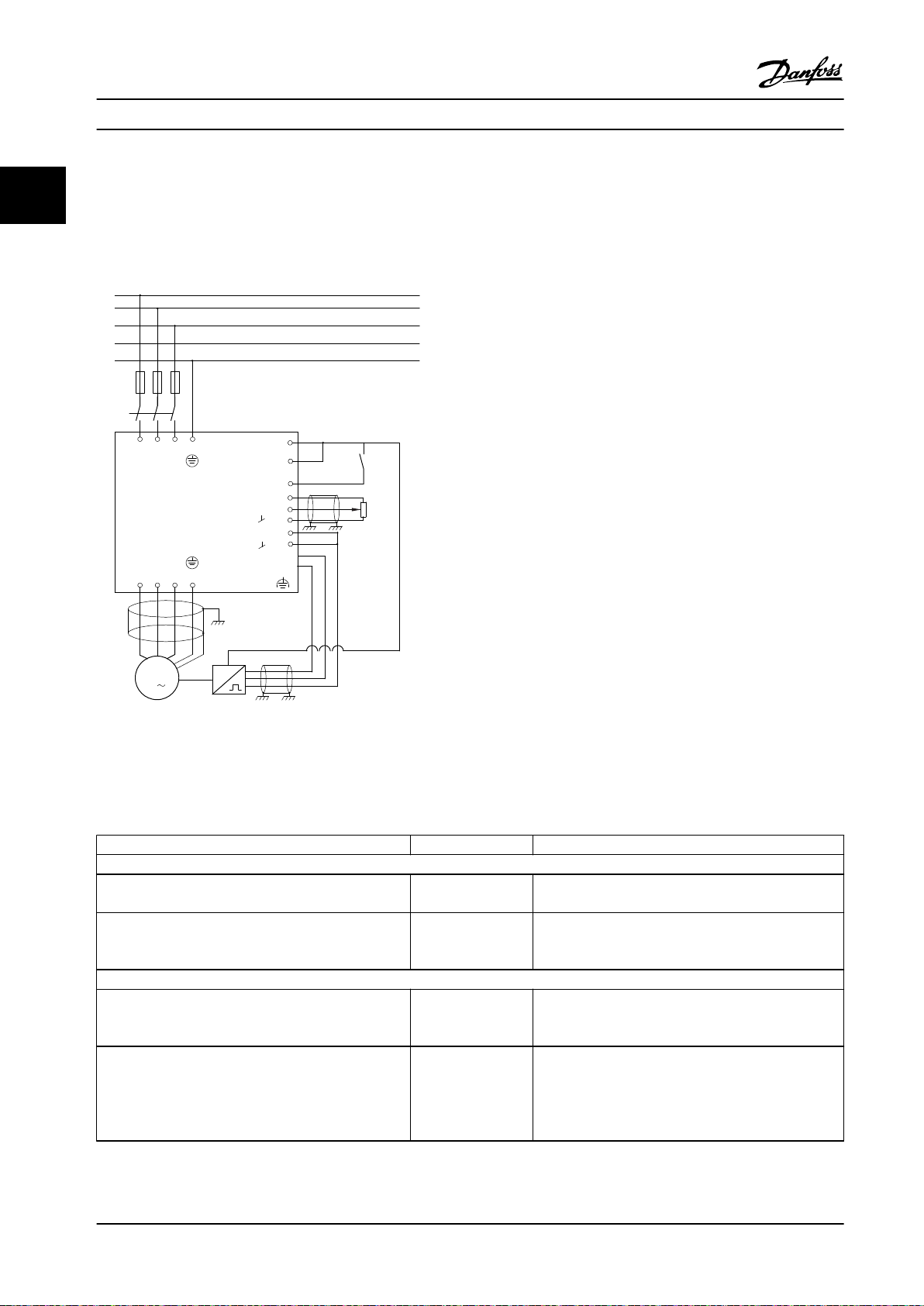
Product Overview and Functi...
VLT® Decentral Drive FCD 302
Example of how to program the speed control
22
In this case, the speed PID control is used to maintain a constant motor speed regardless of the changing load on the
motor. The required motor speed is set via a potentiometer connected to terminal 53. The speed range is 0–1500 RPM
corresponding to 0–10 V over the potentiometer. Starting and stopping is controlled by a switch connected to terminal 18.
The speed PID monitors the actual RPM of the motor by using a 24 V (HTL) incremental encoder as feedback. The feedback
sensor is an encoder (1024 pulses per revolution) connected to terminals 32 and 33.
Figure 2.13 Example - Speed Control Connections
The following must be programmed in the order shown (see explanation of settings in the
301/FC 302 Programming Guide)
In the list, it is assumed that all other parameters and switches remain at their default setting.
Function Parameter Setting
1) Make sure that the motor runs properly. Do the following:
Set the motor parameters using nameplate data. Parameter group 1-2*
Motor Data
Perform an automatic motor adaptation. Parameter 1-29 Auto
matic Motor
Adaptation (AMA)
2) Check that the motor is running and that the encoder is attached properly. Do the following:
Press the [Hand On] LCP key. Check that the motor is
– Set a positive reference.
running and note in which direction it is turning
(referred to as the positive direction).
Go to parameter 16-20 Motor Angle. Turn the motor
slowly in the positive direction. It must be turned so
slowly (only a few RPM) that it can be determined if the
value in parameter 16-20 Motor Angle is increasing or
decreasing.
Parameter 16-20 Moto
r Angle
As specied on motor nameplate.
[1] Enable complete AMA.
(Read-only parameter) Note: An increasing value
overows at 65535 and starts again at 0.
VLT® AutomationDrive FC
22 Danfoss A/S © 05/2018 All rights reserved. MG04H322
Page 25
Product Overview and Functi... Design Guide
Function Parameter Setting
If parameter 16-20 Motor Angle is decreasing, then
change the encoder direction in parameter 5-71 Term
32/33 Encoder Direction.
3) Make sure that the frequency converter limits are set to safe values.
Set acceptable limits for the references. Parameter 3-02 Minim
Check that the ramp settings are within frequency
converter capabilities and allowed application operating
specications.
Set acceptable limits for the motor speed and frequency. Parameter 4-11 Motor
4) Congure the speed control and select the motor control principle.
Activation of speed control. Parameter 1-00 Cong
Selection of motor control principle. Parameter 1-01 Motor
5) Congure and scale the reference to the speed control.
Set up analog input 53 as a reference source. Parameter 3-15 Refere
Scale analog input 53 from 0 RPM (0 V ) to 1500 RPM
(10 V).
6) Congure the 24 V HTL encoder signal as feedback for the motor control and the speed control.
Set up digital input 32 and 33 as encoder inputs. Parameter 5-14 Termi
Select terminal 32/33 as motor feedback. Parameter 1-02 Flux
Select terminal 32/33 as speed PID feedback. Parameter 7-00 Speed
7) Tune the speed control PID parameters.
Use the tuning guidelines when relevant or tune
manually.
8) Finished.
Save the parameter setting to the LCP for safe keeping. Parameter 0-50 LCP
Parameter 5-71 Term
32/33 Encoder
Direction
um Reference
Parameter 3-03 Maxi
mum Reference
Parameter 3-41 Ramp
1 Ramp-up Time
Parameter 3-42 Ramp
1 Ramp-down Time
Speed Low Limit
[RPM]
Parameter 4-13 Motor
Speed High Limit
[RPM]
Parameter 4-19 Max
Output Frequency
uration Mode
Control Principle
nce Resource 1
Parameter group 6-1*
Analog Input 1
nal 32 Digital Input
Parameter 5-15 Termi
nal 33 Digital Input
Motor Feedback
Source
PID Feedback Source
Parameter group 7-0*
Speed PID Ctrl.
Copy
[1] Counterclockwise (if parameter 16-20 Motor Angle is
decreasing).
0 RPM (default).
1500 RPM (default).
Default setting.
Default setting.
0 RPM (default).
1500 RPM (default).
60 Hz (default 132 Hz).
[1] Speed closed loop.
[3] Flux w motor feedb.
Not necessary (default).
Not necessary (default).
[0] No operation (default).
Not necessary (default).
Not necessary (default).
See the guidelines in chapter 2.4.3 Tuning PID Speed
Control.
[1] All to LCP.
2 2
Table 2.4 Speed Control Settings
MG04H322 Danfoss A/S © 05/2018 All rights reserved. 23
Page 26
Product Overview and Functi...
VLT® Decentral Drive FCD 302
2.4.3 Tuning PID Speed Control
22
The following tuning guidelines are relevant when using 1
of the ux motor control principles in applications where
the load is mainly inertial (with a low amount of friction).
The value of parameter 30-83 Speed PID Proportional Gain
depends on the combined inertia of the motor and load,
and the selected bandwidth can be calculated using the
following formula:
Par . 7 − 02 =
Totalinertia k gm2xpar . 1 − 25
Par . 1 − 20x 9550
xBandwidth
NOTICE!
Parameter 1-20 Motor Power [kW] is the motor power in
[kW] (that is, enter 4 kW instead of 4000 W in the
formula).
A practical value for the bandwidth is 20 rad/s. Check the
result of the Parameter 30-83 Speed PID Proportional Gain
calculation against the following formula (not required
when using high-resolution feedback such as a SinCos
feedback):
rad/ s
other factors in the application might limit the
parameter 30-83 Speed PID Proportional Gain to a lower
value.
To minimize the overshoot, parameter 7-03 Speed PID
Integral Time could be set to approximately 2.5 s (varies
with the application).
Parameter 7-04 Speed PID
to 0 until everything else is tuned. If necessary, nish the
tuning by experimenting with small increments of this
setting.
Dierentiation Time should be set
2.4.4 Process PID Control
The process PID Control can be used to control application
parameters that can be measured by a sensor (that is,
pressure, temperature, ow) and be aected by the
connected motor through a pump, fan, or otherwise.
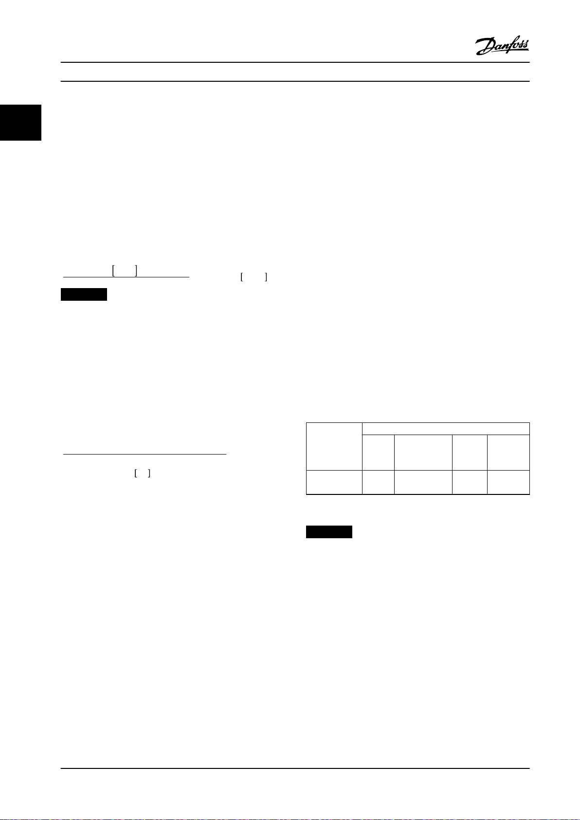
Table 2.5 shows the control congurations where the
process control is possible. When a ux vector motor
control principle is used, take care also to tune the speed
control PID parameters. To see where the speed control is
active, refer to chapter 2.3 Control Structures.
Par . 7 − 02
0 . 01x4xEncoderResolutionxPar . 7 − 06
xMaxtorqueripple %
A good start value for parameter 7-06 Speed PID Lowpass
Filter Time is 5 ms (lower encoder resolution calls for a
higher lter value). Typically, a maximum torque ripple of
3% is acceptable. For incremental encoders, the encoder
resolution is found in either parameter 5-70 Term 32/33
Pulses per Revolution (24 V HTL on standard frequency
converter) or parameter 17-11 Resolution (PPR) (5 V TTL on
VLT® Encoder Input MCB 102 option).
Generally, the practical maximum limit of
parameter 30-83 Speed PID Proportional Gain is determined
by the encoder resolution and the feedback lter time. But
MAX
=
2xπ
Parameter 1-00
Conguration
Mode
[3] Process – Process Process
Table 2.5 Process PID Control Settings
Parameter 1-01 Motor Control Principle
U/f
VVC
+
Flux
sensorles
s
& speed
Flux with
encoder
feedback
Process &
speed
NOTICE!
The process PID control works under the default
parameter setting, but tuning the parameters is highly
recommended to optimize the application control
performance. The 2 ux motor control principles are
specially dependent on proper speed control PID tuning
(before tuning the process control PID) to yield their full
potential.
24 Danfoss A/S © 05/2018 All rights reserved. MG04H322
Page 27
Product Overview and Functi... Design Guide
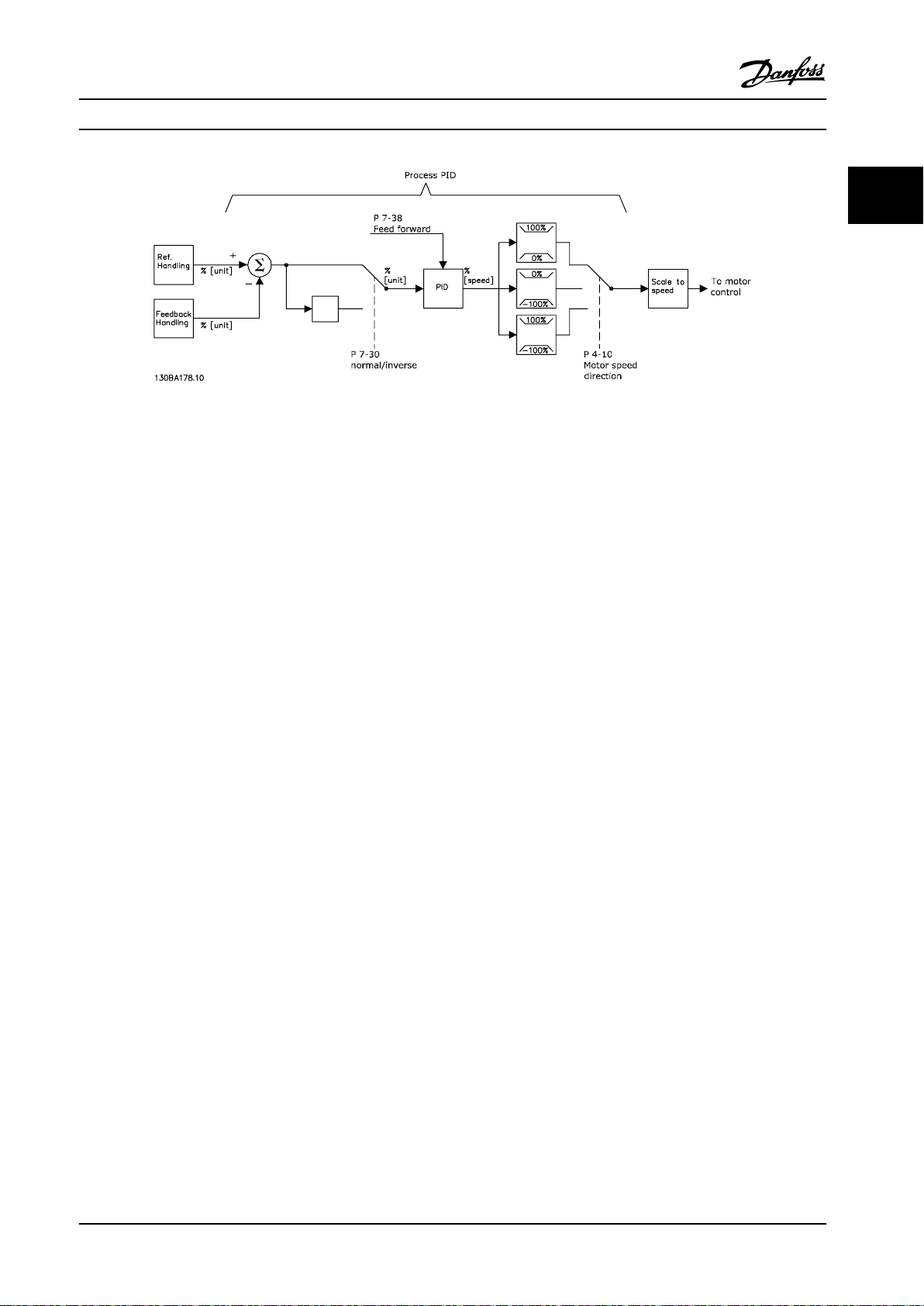
Figure 2.14 Process PID Control Diagram
2 2
MG04H322 Danfoss A/S © 05/2018 All rights reserved. 25
Page 28

Product Overview and Functi...
VLT® Decentral Drive FCD 302
2.4.5 Process Control Relevant Parameters
22
Parameter Description of function
Parameter 7-20 Process CL Feedback 1 Resource Select from which source (that is, analog or pulse input) the process PID should get its
feedback.
Parameter 7-22 Process CL Feedback 2 Resource Optional: Determine if (and from where) the process PID should get an additional
feedback signal. If an additional feedback source is selected, the 2 feedback signals are
added before being used in the process PID control.
Parameter 7-30 Process PID Normal/Inverse
Control
Parameter 7-31 Process PID Anti Windup The anti-wind-up function ensures that when either a frequency limit or a torque limit is
Parameter 7-32 Process PID Controller Start
Value
Parameter 7-33 Process PID Proportional Gain The higher the value - the quicker the control. However, too large value may lead to
Parameter 7-34 Process PID Integral Time Eliminates steady state speed error. Lower value means quick reaction. However, too small
Parameter 7-35 Process PID Dierentiation Time Provides a gain proportional to the rate of change of the feedback. A setting of 0 disables
Parameter 7-36 Process PID Dierentiation Gain
Limit
Parameter 7-38 Process PID Feed Forward
Factor
Parameter 5-54 Pulse Filter Time Constant #29
(Pulse term. 29), parameter 5-59 Pulse Filter
Time Constant #33 (Pulse term. 33),
parameter 6-16 Terminal 53 Filter Time
Constant (Analog term 53),
parameter 6-26 Terminal 54 Filter Time
Constant (Analog term. 54)
Under [0] Normal operation, the process control responds with an increase of the motor
speed if the feedback is getting lower than the reference. In the same situation, but under
[1] Inverse operation, the process control responds with a decreasing motor speed instead.
reached, the integrator is set to a gain that corresponds to the actual frequency. This
avoids integrating on an error that cannot in any case be compensated for with a speed
change. This function can be disabled by selecting [0] O.
In some applications, reaching the required speed/set point can take long time. In such
applications, it might be an advantage to set a xed motor speed from the frequency
converter before the process control is activated. This is done by setting a process PID
start value (speed) in parameter 7-32 Process PID Controller Start Value.
oscillations.
value may lead to oscillations.
the dierentiator.
If there are quick changes in reference or feedback in a given application - which means
that the error changes swiftly - the dierentiator may soon become too dominant. This is
because it reacts to changes in the error. The quicker the error changes, the stronger the
dierentiator gain is. The dierentiator gain can thus be limited to allow setting of the
reasonable dierentiation time for slow changes.
In applications where there is a good (and approximately linear) correlation between the
process reference and the motor speed necessary for obtaining that reference, the feed
forward factor can be used to achieve better dynamic performance of the process PID
control.
If there are oscillations of the current/voltage feedback signal, these can be dampened
with a low-pass lter. This time constant shows the speed limit of the ripples occurring on
the feedback signal.
Example: If the low-pass lter has been set to 0.1 s, the limit speed is 10 RAD/s (the
reciprocal of 0.1 s), corresponding to (10/(2 x π))=1.6 Hz. This means that all currents/
voltages that vary by more than 1.6 oscillations per second are dampened by the lter.
The control is only carried out on a feedback signal that varies by a frequency (speed) of
less than 1.6 Hz.
The low-pass lter improves steady state performance but selecting a too large lter time
deteriorates the dynamic performance of the process PID control.
Table 2.6 Parameters are Relevant for the Process Control
26 Danfoss A/S © 05/2018 All rights reserved. MG04H322
Page 29
130BC966.10
5
6
1
100kW
n °CW
2
3
4
ON
WARNING
ALARM
Bus MS NS2NS1
Product Overview and Functi... Design Guide
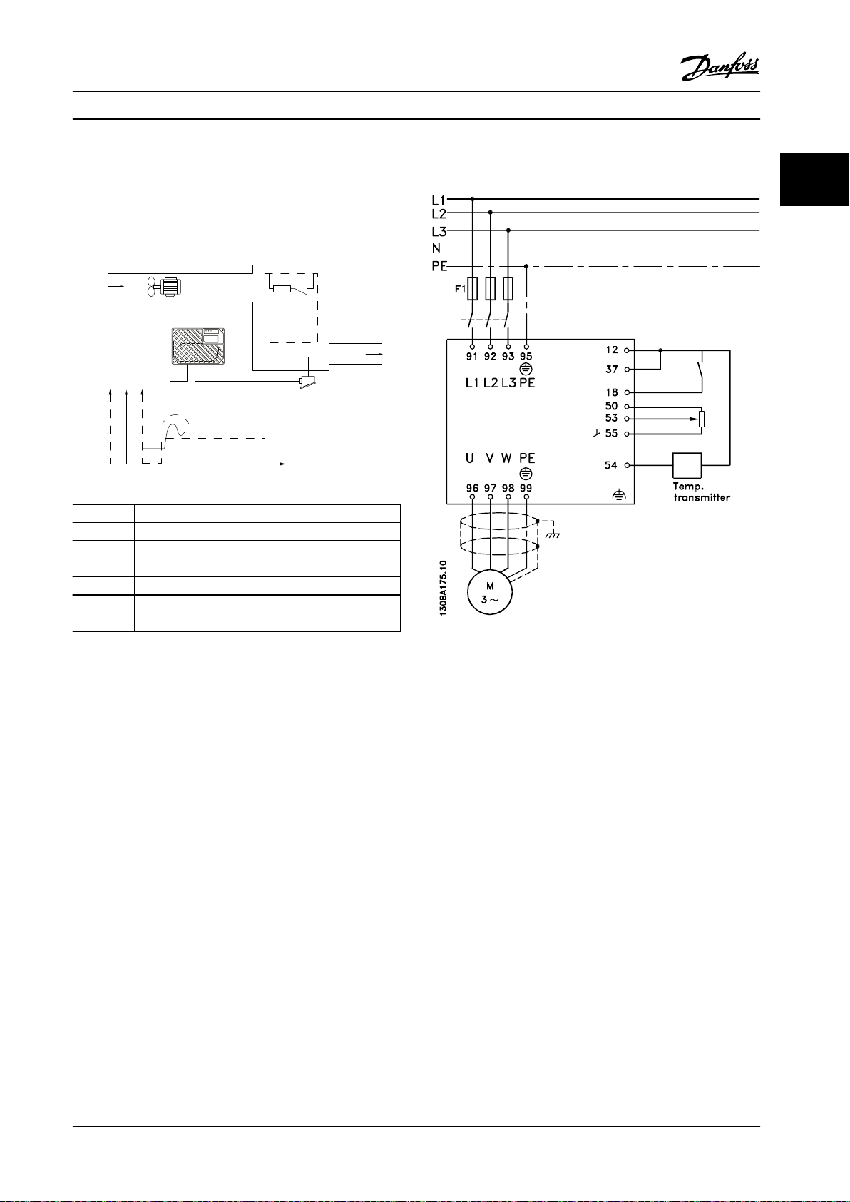
2.4.6 Example of Process PID Control
Figure 2.15 is an example of a process PID control used in a
ventilation system.
Item Description
1 Cold air
2 Heat generating process
3 Temperature transmitter
4 Temperature
5 Fan speed
6 Heat
2 2
Figure 2.16 Two-wire Transmitter
Figure 2.15 Process PID Control in Ventilation System
1. Start/stop via a switch connected to terminal 18.
In a ventilation system, the temperature is to be settable
from -5 to +35 °C (23–95 °F) with a potentiometer of 0–
10 V. The task of the process control is to maintain
temperature at a constant preset level.
2. Temperature reference via potentiometer (-5 to
35 °C (23–95 °F), 0–10 V DC) connected to
terminal 53.
3. Temperature feedback via transmitter (-10 to
40 °C (14–104 °F), 4–20 mA) connected to
The control is of the inverse type, which means that when
the temperature increases, the ventilation speed is
terminal 54. Switch S202 set to ON (current
input).
increased as well, to generate more air. When the
temperature drops, the speed is reduced. The transmitter
used is a temperature sensor with a working range of -10
to +40 °C (14–104 °F), 4–20 mA. Minimum/maximum
speed 300/1500 RPM.
MG04H322 Danfoss A/S © 05/2018 All rights reserved. 27
Page 30
Product Overview and Functi...
VLT® Decentral Drive FCD 302
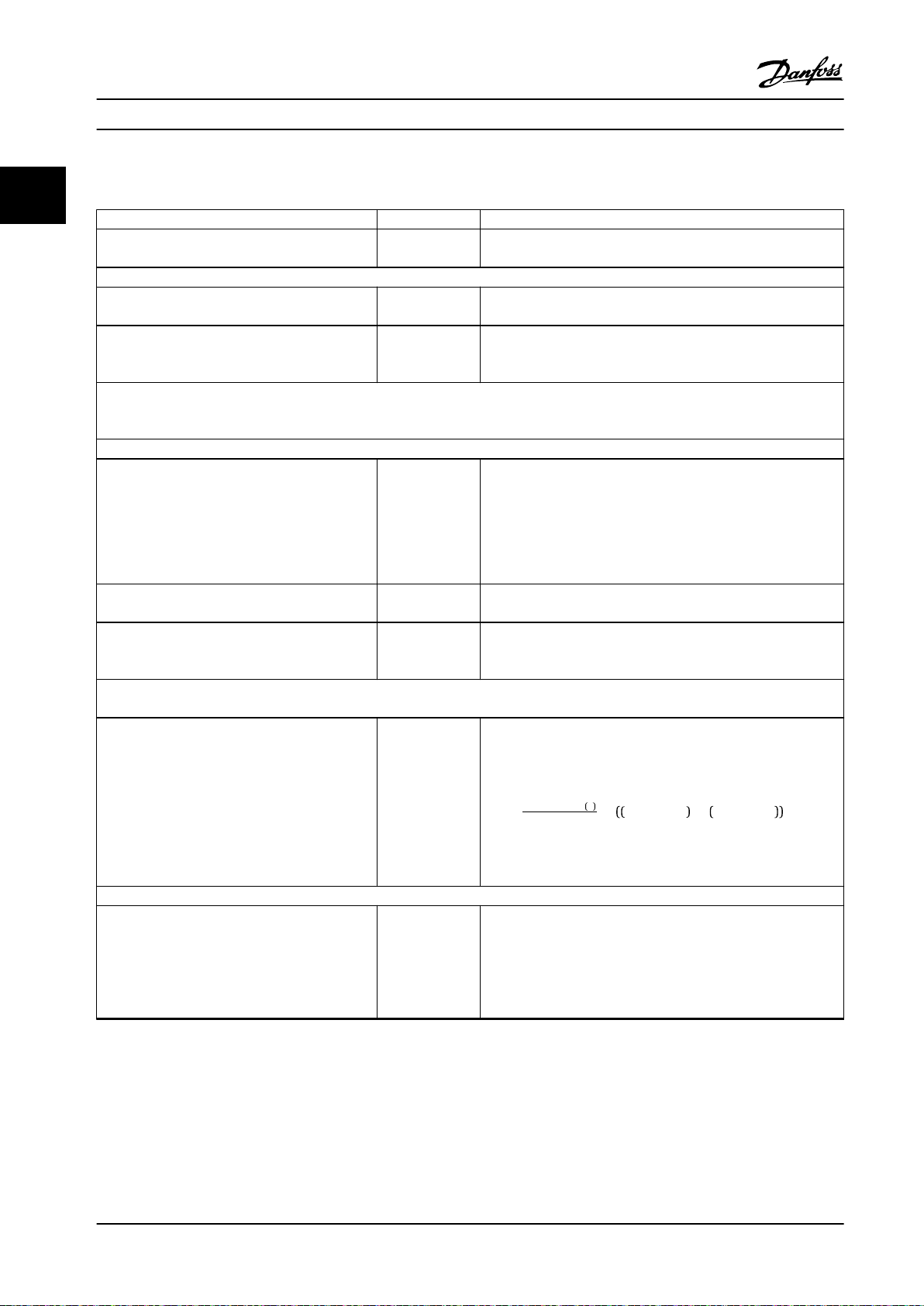
2.4.7 Programming Order
22
Function Parameter Setting
Initialize the frequency converter. Parameter 14-22
Operation Mode
1) Set motor parameters.
Set the motor parameters according to nameplate
data.
Perform a full AMA. Parameter 1-29 Au
2) Check that motor is running in the right direction.
When the motor is connected to the frequency converter with straight forward phase order as U - U; V- V; W - W, the motor shaft usually
turns clockwise seen into shaft end.
Press [Hand On] LCP key. Check shaft direction by applying a manual reference.
If the motor turns opposite of the required
direction:
1. Change motor direction in
parameter 4-10 Motor Speed Direction.
2. Turn o mains - wait for DC link to discharge -
switch 2 of the motor phases.
Set conguration mode. Parameter 1-00 Co
Set local mode conguration Parameter 1-05 Lo
3) Set reference conguration, that is, the range for handling of reference. Set scaling of analog input in parameter group 6-** Analog
In/Out.
Set reference/feedback units.
•
Set minimum reference (10 °C (50 °F)).
•
Set maximum reference (80 °C (176 °F)).
•
If set value is determined from a preset value
(array parameter), set other reference sources to
no function.
4) Adjust limits for the frequency converter:
Set ramp times to an appropriate value as 20 s. Parameter 3-41 Ra
Parameter group
1-2* Motor Data
tomatic Motor
Adaptation (AMA)
Parameter 4-10 M
otor Speed
Direction
nguration Mode
cal Mode Congu-
ration
Parameter 3-01 Re
ference/Feedback
Unit
Parameter 3-02 Mi
nimum Reference
Parameter 3-03 M
aximum Reference
Parameter 3-10 Pr
eset Reference
mp 1 Ramp-up
Time
Parameter 3-42 Ra
mp 1 Ramp- down
Time
[2] Initialization - make a power-cycle - press reset.
As stated on motor nameplate.
[1] Enable complete AMA.
Select correct motor shaft direction.
[3] Process.
[0] Speed Open Loop.
[60] °C Unit shown on display.
-5 °C.
35 °C.
[0] 35%.
Par . 3 − 10
Ref =
Parameter 3-14 Preset Relative Reference to parameter 3-18 Relative
Scaling Reference Resource, [0] = No function
20 s.
20 s.
100
0
× Par . 3 − 03 − par . 3 − 02 = 24, 5°C
28 Danfoss A/S © 05/2018 All rights reserved. MG04H322
Page 31

Product Overview and Functi... Design Guide
Function Parameter Setting
Set minimum speed limits.
•
Set motor speed maximum limit.
•
Set maximum output frequency.
•
Set S201 or S202 to wanted analog input function (Voltage (V) or milliamps (I))
Parameter 4-11 M
otor Speed Low
Limit [RPM]
Parameter 4-13 M
otor Speed High
Limit [RPM]
Parameter 4-19 M
ax Output
Frequency
300 RPM.
1500 RPM.
60 Hz.
NOTICE!
Switches are sensitive - Make a power-cycle keeping the default setting of V.
5) Scale analog inputs used for reference and feedback.
Set terminal 53 low voltage.
•
Set terminal 53 high voltage.
•
Set terminal 54 low feedback value.
•
Set terminal 54 high feedback value.
•
Set feedback source.
•
6) Basic PID settings.
Process PID normal/inverse. Parameter 7-30 Pr
Process PID anti-wind-up. Parameter 7-31 Pr
Process PID start speed. Parameter 7-32 Pr
Save parameters to LCP. Parameter 0-50 LC
Parameter 6-10 Te
rminal 53 Low
Voltage
Parameter 6-11 Te
rminal 53 High
Voltage
Parameter 6-24 Te
rminal 54 Low
Ref./Feedb. Value
Parameter 6-25 Te
rminal 54 High
Ref./Feedb. Value
Parameter 7-20 Pr
ocess CL Feedback
1 Resource
ocess PID Normal/
Inverse Control
ocess PID Anti
Windup
ocess PID
Controller Start
Value
P Copy
0 V.
10 V.
-5 °C.
35 °C.
[2] Analog input 54.
[0] Normal.
[1] On.
300 RPM.
[1] All to LCP.
2 2
Table 2.7 Example of Process PID Control Set-up
MG04H322 Danfoss A/S © 05/2018 All rights reserved. 29
Page 32

130BA183.10
y(t)
t
P
u
Product Overview and Functi...
VLT® Decentral Drive FCD 302
2.4.8 Process Controller Optimization
2.4.9 Ziegler Nichols Tuning Method
22
The basic settings have now been made. All that needs to
be done is to optimize the proportional gain, the
integration time, and the dierentiation time
(parameter 7-33 Process PID Proportional Gain,
parameter 7-34 Process PID Integral Time,
parameter 7-35 Process PID Dierentiation Time). In most
processes, this can be done by following these guidelines:
1. Start the motor.
2. Set parameter 7-33 Process PID Proportional Gain
to 0.3 and increase it until the feedback signal
again begins to vary continuously. Then reduce
the value until the feedback signal has stabilized.
Now lower the proportional gain by 40–60%.
3. Set parameter 7-34 Process PID Integral Time to
20 s and reduce the value until the feedback
signal again begins to vary continuously. Increase
the integration time until the feedback signal
stabilizes, followed by an increase of 15–50%.
4. Only use parameter 7-35 Process PID
Time for very fast-acting systems only (dieren-
tiation time). The typical value is 4 times the set
integration time. The dierentiator should only be
used when the setting of the proportional gain
and the integration time has been fully
optimized. Make sure that oscillations on the
feedback signal are suciently dampened by the
lowpass lter on the feedback signal.
Dierentiation
NOTICE!
If necessary, start/stop can be activated several times to
provoke a variation of the feedback signal.
To tune the PID controls of the frequency converter,
Danfoss recommends the Ziegler Nichols tuning method.
NOTICE!
Do not use the Ziegler Nichols Tuning method in
applications that could be damaged by the oscillations
created by marginally stable control settings.
The criteria for adjusting the parameters are based on
evaluating the system at the limit of stability rather than
on taking a step response. Increase the proportional gain
until observing continuous oscillations (as measured on
the feedback), that is, until the system becomes marginally
stable. The corresponding gain (Ku) is called the ultimate
gain and is the gain, at which the oscillation is obtained.
The period of the oscillation (Pu) (called the ultimate
period) is determined as shown in Figure 2.17 and should
be measured when the amplitude of oscillation is small.
1. Select only proportional control, meaning that
the integral time is set to the maximum value,
while the dierentiation time is set to 0.
2. Increase the value of the proportional gain until
the point of instability is reached (sustained
oscillations) and the critical value of gain, Ku, is
reached.
3. Measure the period of oscillation to obtain the
critical time constant, Pu.
4. Use Table 2.8 to calculate the necessary PID
control parameters.
The process operator can do the nal tuning of the control
iteratively to yield satisfactory control.
Figure 2.17 Marginally Stable System
30 Danfoss A/S © 05/2018 All rights reserved. MG04H322
Page 33

Speed
Coast inverse (27)
Coast inverse
Safe
torque off
130BC985.10
NVR B03B04P B02 B01
2012G B07B0820 B06 B05
372013 B11B1237 B10 B09
1212
12
121212 55 53
271918
33
3229 50 54
202020 202020 55 42
Product Overview and Functi... Design Guide
Type of
control
PI-control 0.45 x K
PID tight
control
PID some
overshoot
Table 2.8 Ziegler Nichols Tuning for Regulator
Proportional
gain
u
0.6 x K
u
0.33 x K
u
Integral time Dierentiation
time
0.833 x P
0.5 x P
u
0.5 x P
u
u
0.125 x P
0.33 x P
–
u
u
2.5 Control Cables and Terminals
2.5.1 Control Cable Routing
A 24 V DC external supply can be used as low voltage
supply to the control card and any option cards installed.
This enables full operation of the LCP (including parameter
setting) without connection to mains.
NOTICE!
A warning of low voltage is given when 24 V DC has
been connected; however, there is no tripping.
Default settings:
27 = [2] Coast inverse parameter 5-10 Terminal 18 Digital
Input
37 = Safe Torque O inverse
2 2
WARNING
ELECTRICAL SHOCK HAZARD
Without galvanic isolation (type PELV), the control
terminals impose an electrical shock hazard. Failure to
follow the recommendations, may lead to death or
serious injury.
Use 24 V DC supply of type PELV to ensure
•
correct galvanic isolation (type PELV).
2.5.2 DIP Switches
2.5.3 Basic Wiring Example
Connect terminals 27 and 37 to +24 V terminals 12 and 13,
as shown in Figure 2.18.
Figure 2.18 Basic Wiring Example
MG04H322 Danfoss A/S © 05/2018 All rights reserved. 31
Page 34

130BC384.10
3-phase
power
input
Mechanical
brake
+10 V DC
-10 V DC+10 V DC
0/4-20 mA
-10 V DC+10 V DC
0/4-20 mA
91 (L1)
92 (L2)
93 (L3)
95 (PE)
122(MBR+)
123(MBR-)
50 (+10 V OUT)
53 (A IN)
54 (A IN)
55 (COM A IN)
12 (+24 V OUT)
13 (+24 V OUT)
18 (D IN)
19 (D IN)
20 (COM D IN)
27 (D IN/OUT)
29 (D IN/OUT)
24V
OV
32 (D IN)
33 (D IN)
37 (D IN)
S201
S202
ON/I=0-20mA
OFF/U=0-10V
P 5-00
24 V (NPN)
0 V (PNP)
24 V (NPN)
0 V (PNP)
24 V (NPN)
0 V (PNP)
24 V (NPN)
0 V (PNP)
24 V (NPN)
0 V (PNP)
24 V (NPN)
0 V (PNP)
Switch mode
power supply
10 V DC
15 mA
24 V DC
600 mA
(U) 96
(U) 97
(W) 98
(PE) 99
Motor
Brake
resistor
(R+) 82
(R-) 81
Relay1
Relay2
03
02
01
06
05
04
240 V AC, 2A
240 V AC, 2A
400 V AC, 2A
Analog output
0/4–20 mA
(COM A OUT) 39
(A OT) 42
ON=Terminated
OFF=Open
S801
S801
GX
(N RS485) 69
(P RS485) 68
5V
RS485
Interface
(COM RS485) 61
(PNP) = Source
(NPN) = Sink
RS485
ON
1 2
ON
1 2
ON
1 2
0 V
VCXA
PROFIBUS
interface
GND1
GND1
RS485
66
63
62
67
GX
Product Overview and Functi...
VLT® Decentral Drive FCD 302
2.5.4 Electrical Installation, Control Cables
22
Figure 2.19 Electrical Terminals without Options
A = analog, D = digital
Terminal 37 is used for Safe Torque O.
Relay 2 has no function when the frequency converter has mechanical brake output.
32 Danfoss A/S © 05/2018 All rights reserved. MG04H322
Page 35

130BC987.10
Safe
torque off
Safe
torque off
PNP (Source)
Digital input wiring
NPN (Sink)
Digital input wiring
NVR B03B04P B02 B01
2012G B07B0820 B06 B05
372013 B11B1237 B10 B09
1212
12
121212 55 53
271918 333229 50 54
202020 202020 55 42
NVR B03B04P B02 B01
2012G B07B0820 B06 B05
372013 B11B1237 B10 B09
1212
12
121212 55 53
271918
33
3229 50 54
202020 202020 55 42
3
7
2
0
1
3
B
1
1
B
1
2
3
7
B
1
0
B
0
9
2
0
1
2
G
B
0
7
B
0
8
2
0
B
0
6
B
0
5
N
V
R
B
0
3
B
0
4
P
B
0
2
B
0
1
Z
A
/Z
B
+5V
/B
GND
/A
A
+24V
B
GND
130BC998.10
Product Overview and Functi... Design Guide
Long control cables and analog signals may in rare cases
result in 50/60 Hz ground loops due to noise from mains
supply cables. If this occurs, it may be necessary to break
the shield or insert a 100 nF capacitor between shield and
chassis. Connect the digital and analog inputs and outputs
separately to the common inputs (terminal 20, 55, 39) to
avoid ground currents from both groups aecting other
groups. For example, switching on the digital input may
disturb the analog input signal.
2.5.5 Relay Output
The relay output with the terminals 01, 02, 03 and 04, 05,
06 has a capacity of maximum 240 V AC, 2 A. Minimum
24 V DC, 10 mA, or 24 V AC, 100 mA can be used for
indicating status and warnings. The 2 relays are physically
located on the installation card. These are programmable
through parameter group 5-4* Relays. The relays are Form C,
meaning each has 1 normally open contact and 1 normally
closed contact on a single throw. The contacts of each
relay are rated for a maximum load of 240 V AC at 2 amps.
Relay 1
Terminal 01: Common
•
Terminal 02: Normal open 240 V AC
•
Terminal 03: Normal closed 240 V AC
•
Relay 2
Terminal 04: Common
•
Terminal 05: Normal open 240 V AC
•
Terminal 06: Normal closed 240 V AC
•
Relay 1 and relay 2 are programmed in
parameter 5-40 Function Relay, parameter 5-41 On Delay,
Relay, and parameter 5-42
O Delay, Relay.
2 2
Figure 2.20 Input Polarity of Control Terminals
NOTICE!
To comply with EMC emission specications, shielded/
armored cables are recommended. If an unshielded/
unarmored cable is used, see chapter 2.9.7 EMC Test
Results for more information.
MG04H322 Danfoss A/S © 05/2018 All rights reserved. 33
Figure 2.21 Relay Connection
Page 36

Product Overview and Functi...
VLT® Decentral Drive FCD 302
2.6 Handling of Reference
22
Local reference
The local reference is active when the frequency converter is operated with [Hand On] key active. Adjust the reference by
[▲]/[▼] and [◄]/[►] arrows, respectively.
Remote reference
The reference handling system for calculating the remote reference is shown in Figure 2.22.
Figure 2.22 Remote Reference
34 Danfoss A/S © 05/2018 All rights reserved. MG04H322
Page 37

Product Overview and Functi... Design Guide
The remote reference is calculated once in every scan
interval and initially consists of 2 types of reference
inputs:
X (the external reference): A sum (see
•
parameter 3-04 Reference Function) of up to 4
externally selected references. These comprise any
combination (determined by the setting of
parameter 3-15 Reference Resource 1,
parameter 3-16 Reference Resource 2, and
parameter 3-17 Reference Resource 3) of a xed
preset reference (parameter 3-10 Preset Reference),
variable analog references, variable digital pulse
references, and various eldbus references in the
unit, which controls the frequency converter ([Hz],
[RPM], [Nm] and so on).
Y (the relative reference): A sum of 1 xed preset
•
reference (parameter 3-14 Preset Relative Reference)
and 1 variable analog reference
(parameter 3-18 Relative Scaling Reference
Resource) in [%].
The 2 types of reference inputs are combined in the
following formula: Remote reference=X+X*Y/100%. If
relative reference is not used, set parameter 3-18 Relative
Scaling Reference Resource to [0] No function and
parameter 3-14 Preset Relative Reference to 0%. The catch
up/slow down function and the freeze reference function can
both be activated by digital inputs on the frequency
converter. The functions and parameters are described in
the VLT® AutomationDrive FC 301/FC 302 Programming
Guide.
The scalings of analog references are described in
parameter groups 6-1* Analog Input 1 and 6-2* Analog Input
2, and the scaling of digital pulse references are described
in parameter group 5-5* Pulse Input.
Reference limits and ranges are set in parameter group 3-0*
Reference Limits.
2 2
Figure 2.23 Reference Range=[0] Min-Max
Figure 2.24 Reference Range=[1] -Max-Max
The value of parameter 3-02 Minimum Reference cannot be
set to less than 0, unless parameter 1-00 Conguration
Mode is set to [3] Process. In that case, the following
relations between the resulting reference (after clamping)
and the sum of all references is as shown in Figure 2.25.
2.6.1 Reference Limits
Parameter 3-00 Reference Range, parameter 3-02 Minimum
Reference, and parameter 3-03 Maximum Reference together
dene the allowed range of the sum of all references. The
sum of all references is clamped when necessary. The
relation between the resulting reference (after clamping) is
shown in Figure 2.23/Figure 2.24 and the sum of all
references is shown in Figure 2.25.
Figure 2.25 Sum of all References
MG04H322 Danfoss A/S © 05/2018 All rights reserved. 35
Page 38

(RPM)
Resource output
Resource
input
Terminal X low
Terminal X
high
Low reference/feedback value
High reference/feedback
value
130BA181.10
-1500
-6 8 (V)
1500
-10 10
P1
P2
0
-600
(RPM)
Resource output
Resource
input
Terminal X low
Terminal X
high
Low reference/feedback value
High reference/feedback
value
130BA182.10
-1500
-6 8 (V)
1500
-10 10
P1
P2
0
-600
Product Overview and Functi...
VLT® Decentral Drive FCD 302
2.6.2 Scaling of Preset References and Bus References
22
Preset references are scaled according to the following
rules:
When parameter 3-00 Reference Range is set to [0]
•
Min-Max : 0% reference equals 0 [unit] where unit
can be any unit, for example RPM, m/s, bar, and
so on. 100% reference equals the maximum (abs
(parameter 3-03 Maximum Reference), abs
(parameter 3-02 Minimum Reference)).
When parameter 3-00 Reference Range: [1] -Max to
•
+Max 0% reference equals 0 [unit] -100%
reference equals -Maximum reference 100%
reference equals maximum reference.
2.6.3 Scaling of Analog and Pulse References and Feedback
References and feedback are scaled from analog and pulse
inputs in the same way. The only dierence is that a
reference above or below the specied minimum and
maximum endpoints (P1 and P2 in Figure 2.26) are
clamped whereas a feedback above or below is not.
Bus references are scaled according to the following
rules:
When parameter 3-00 Reference Range: [0] Min to
•
Max. To obtain maximum resolution on the bus
reference the scaling on the bus is: 0% reference
equals minimum reference and 100% reference
equals maximum reference.
When parameter 3-00 Reference Range: [1] -Max to
•
+Max -100% reference equals maximum reference
100% reference equals max reference.
Figure 2.26 Scaling of Analog and Pulse References and
Feedback
36 Danfoss A/S © 05/2018 All rights reserved. MG04H322
Figure 2.27 Scaling of Reference Output
The endpoints P1 and P2 are dened by the parameters in
Table 2.9, depending on which analog or pulse input is
used.
Page 39

(RPM)
Resource output
Resource
input
Quadrant 2
Quadrant 3
Quadrant 1
Quadrant 4
Terminal X
low
Terminal X
high
Low reference/feedback
value
High reference/feedback
value
-1 1
130BA179.10
-1500
-6 6
(V)
1500
-10 10
P1
P2
0
Product Overview and Functi... Design Guide
Analog 53
S201=OFF
P1=(Minimum input value, minimum reference value)
Minimum reference value Parameter 6-14
Terminal 53
Low Ref./Feedb.
Value
Minimum input value Parameter 6-10
Terminal 53
Low Voltage
[V]
P2=(Maximum input value, maximum reference value)
Maximum reference value Parameter 6-15
Terminal 53
High Ref./
Feedb. Value
Maximum input value Parameter 6-11
Terminal 53
High Voltage
[V]
Table 2.9 Input and Reference Endpoint Values
Analog 53
S201=ON
Parameter 6-14 T
erminal 53 Low
Ref./Feedb. Value
Parameter 6-12 T
erminal 53 Low
Current [mA]
Parameter 6-15 T
erminal 53 High
Ref./Feedb. Value
Parameter 6-13 T
erminal 53 High
Current [mA]
2.6.4 Dead Band Around Zero
Analog 54
S202=OFF
Parameter 6-24
Terminal 54
Low Ref./Feedb.
Value
Parameter 6-20
Terminal 54
Low Voltage
[V]
Parameter 6-25
Terminal 54
High Ref./
Feedb. Value
Parameter 6-21
Terminal 54
High
Voltage[V]
Analog 54
S202=ON
Parameter 6-24 T
erminal 54 Low
Ref./Feedb. Value
Parameter 6-22 T
erminal 54 Low
Current [mA]
Parameter 6-25 T
erminal 54 High
Ref./Feedb. Value
Parameter 6-23 T
erminal 54 High
Current[mA]
Pulse input 29 Pulse input 33
Parameter 5-52
Term. 29 Low
Ref./Feedb. Value
Parameter 5-50
Term. 29 Low
Frequency [Hz]
Parameter 5-53
Term. 29 High
Ref./Feedb. Value
Parameter 5-51
Term. 29 High
Frequency [Hz]
Parameter 5-57 Term.
33 Low Ref./Feedb.
Value
Parameter 5-55 Term.
33 Low Frequency
[Hz]
Parameter 5-58 Term.
33 High Ref./Feedb.
Value
Parameter 5-56 Term.
33 High Frequency
[Hz]
2 2
Sometimes the reference (in rare cases also the feedback)
should have a dead band around zero (that is, to make
sure that the machine is stopped when the reference is
near 0).
To make the dead band active and to set the amount of
dead band, the following settings must be done:
The size of the dead band is dened by either P1 or P2 as
shown in Figure 2.28.
Either minimum reference value (see Table 2.9 for
•
relevant parameter) or maximum reference value
must be 0. In other words, either P1 or P2 must
be on the X-axis in Figure 2.28.
And both points
•
dening the scaling graph are in
the same quadrant.
Figure 2.28 Dead Band
MG04H322 Danfoss A/S © 05/2018 All rights reserved. 37
Page 40

(RPM)
Resource output
Resource
input
Quadrant 2
Quadrant 3
Quadrant 1
Quadrant 4
Terminal X
low
Terminal X
high
Low reference/feedback
value
High reference/feedback
value
-1 1
130BA180.10
-1500
-6 6
(V)
1500
-10 10
P1
P2
0
Product Overview and Functi...
VLT® Decentral Drive FCD 302
22
Figure 2.29 Reverse Dead Band
If endpoint 2 is placed in either quadrant 1 or quadrant 4,
a reference endpoint of, for example, P1=(1 V, 0 RPM)
results in a -1 V to +1 V dead band.
38 Danfoss A/S © 05/2018 All rights reserved. MG04H322
Page 41

Product Overview and Functi... Design Guide
Case 1: Positive reference with dead band, digital input to trigger reverse
This case shows how reference input with limits inside minimum to maximum limits clamps.
2 2
Figure 2.30 Example 1 - Positive Reference
MG04H322 Danfoss A/S © 05/2018 All rights reserved. 39
Page 42

Product Overview and Functi...
Case 2: Positive reference with dead band, digital input to trigger reverse. Clamping rules.
22
This case shows how reference input with limits outside -maximum to +maximum limits clamps to the inputs low and high
limits before addition to external reference. The case also shows how the external reference is clamped to -maximum to
+maximum by the reference algorithm.
VLT® Decentral Drive FCD 302
Figure 2.31 Example 2 - Positive Reference
40 Danfoss A/S © 05/2018 All rights reserved. MG04H322
Page 43

Product Overview and Functi... Design Guide
Case 3: Negative to positive reference with dead band, sign determines the direction, -maximum to +maximum
2 2
Figure 2.32 Example 3 - Positive to Negative Reference
Brake Functions
2.7
Brake function is applied for braking the load on the
motor shaft, either as dynamic brake or static braking.
NOTICE!
A frequency converter cannot provide Safe Torque O
control of a mechanical brake. A redundancy circuitry for
the brake control must be included in the installation.
2.7.1 Mechanical Brake
A mechanical holding brake mounted directly on the
motor shaft normally performs static braking. In some
applications (usually synchronous permanent motors), the
static holding torque holds the motor shaft. The holding
brake is either controlled by a PLC, directly by a relay, or a
digital output from the frequency converter.
MG04H322 Danfoss A/S © 05/2018 All rights reserved. 41
Page 44

I
Lm
D
L
MOV
MOV
L 3
L2
MBR +
MBR -
1
2
3
4
5
6
V
MBR
V
L3-L2
130BD547.11
MOV
Product Overview and Functi...
VLT® Decentral Drive FCD 302
2.7.1.1 Mechanical Brake Selection Guide
22
and Electrical Circuit Description
within the electrical specication (voltage, current, and so
on) or with external relays. If the frequency converter is
congured without brake, the internal electrical control
VLT® Decentral Drive FCD 302 can be congured with or
without a brake (see position 18 in Figure 6.1).
If the inverter part is congured with brake, relay 1 can be
congured for various applications, while relay 2 should be
reserved only for the mechanical brake. Relay 2 is mounted
inside the installation box, but in this conguration state it
is not active.
The mechanical brake coil can be powered by a low
voltage (of 24 V DC) or from mains line AC voltage.
If the mechanical brake is a 24 V DC type, 1 of the 2
signal for relay 2 is active.
If the brake is powered by mains supply, or a mains
rectied DC voltage, it is recommended to order the FCD
302 with a mechanical brake. In this case, all the parameter
settings for relay 2 now control the internal solid-state
switch which gives the output voltage at the MBR+ and
MBR- terminals. In some motors, this mechanical brake can
be of AC-type or DC-type. If the unit is AC-type, the
mechanical brake has an internal diode D and the internal
MOV, as described in the electrical diagram in Figure 2.33.
custom relays, relay 1, or a functional relay 2, can be used
1 Inverter part
2 MBR+ terminal 122
3 Mechanical brake coil
4 MBR- terminal 123
5 Solid state switch
6 Galvanic isolated control circuit
Figure 2.33 Electrical Diagram of Mechanical Brake
42 Danfoss A/S © 05/2018 All rights reserved. MG04H322
Page 45

VMBR
VL1-L2
VMBR
ILm
130BD199.10
300; 135
320; 144
340; 153
380; 171
400; 180
440;198
480; 216
500; 225
520; 234
100
120
140
160
180
200
220
240
260
300 350 400 450 500 550
Average Outpu t Voltage (Vdc)
Input Mains Line Voltage (Vrms)
130BD200.10
Product Overview and Functi... Design Guide
The supply voltage is derived from the mains voltage
between phases L2 and L3, which is passed through a
single pulse diode rectication.
The output voltage of solid-state supply is not a constant
value, but rather a pulsed voltage with an average level
direct dependent on the mains voltage, as shown in
Figure 2.34:
2 2
Figure 2.35 Average Output Voltage
It is possible to supply the mechanical brake in the motor
with both DC and AC voltage. The output voltage is
rectied by the internal diode inside the mechanical brake
unit circuit. The average voltage applied to the brake coil
remains at the same value.
V
ILm Instant line voltage
Mechanical brake voltage
MBR
Figure 2.34 Instant Voltage V
with its average level of V
MBR
MBR
This rectied voltage is applied to the mechanical brake
inductor, with the smoothed current shape ILm.
The voltage shown in Figure 2.33 has the amplitude of the
line voltage and an average voltage level calculated as:
V
= 0.45 x V
MBR(DC)
AC
Examples:
VAC = 400 V
VAC = 480 V
rms
rms
⇒ V
⇒ V
= 180 VDC.
MBR
= 216 VDC.
MBR
The average level of output voltage is directly determined
by the amplitude of the line voltage measured between
phases L1 and L2.
NOTICE!
Maximum nominal voltage = 480 AC.
2.7.1.2 Mechanical Brake Control
For hoisting applications, it is necessary to be able to
control an electro-magnetic brake. For controlling the
brake, a relay output (relay 1 or relay 2/solid state brake)
or a programmed digital output (terminal 27 or 29) is
required. Normally, this output must be closed for as long
as the frequency converter is unable to hold the motor, for
example, because of excess load. For applications with an
electro-magnetic brake, select [32] mechanical brake control
in 1 of the following parameters:
Parameter 5-40 Function Relay (Array parameter),
•
Parameter 5-30 Terminal 27 Digital Output, or
•
Parameter 5-31 Terminal 29 digital Output
•
When [32] mechanical brake control is selected, the
mechanical brake relay stays closed during start until the
output current is above a preset level. Select the preset
level in parameter 2-20 Release Brake Current. During stop,
the mechanical brake closes when the speed is below the
level selected in parameter 2-21 Activate Brake Speed [RPM].
When the frequency converter is brought into an alarm
condition (that is, an overvoltage situation), or during Safe
Torque O, the mechanical brake immediately cuts in.
MG04H322 Danfoss A/S © 05/2018 All rights reserved. 43
Page 46

130BC970.10
Start
term.18
1=on
Shaft speed
Start delay time
on
Brake delay time
Time
Output current
Relay 01or
Relay 02/solid
state brake
Pre-magnetizing
current or
DC hold current
Reaction time EMK brake
Par 2-20
Release brake current
Par 1-76 Start current/
Par 2-00 DC hold current
Par 1-74
Start speed
Par 2-21
Activate brake
speed
Mechanical brake
locked
Mechanical brake
free
Par 1-71
Par 2-23
o
0=o
Product Overview and Functi...
VLT® Decentral Drive FCD 302
22
Figure 2.36 Mechanical Brake Control for Hoisting Applications
In hoisting/lowering applications, it must be possible to
control an electromechanical brake.
Step-by-step description
To control the mechanical brake, use any relay
•
output, digital output (terminal 27 or 29), or
solid-state brake voltage output (terminals 122–
123). Use a suitable contactor when required.
Ensure that the output is switched o as long as
•
the frequency converter is unable to drive the
motor. For example, due to the load being too
heavy, or when the motor is not yet mounted.
Select [32] mechanical brake control in parameter
•
group 5-4* Relays (or in parameter group 5-3*
Digital Outputs) before connecting the mechanical
brake.
The brake is released when the motor current
•
exceeds the preset value in
parameter 2-20 Release Brake Current.
The brake is engaged when the output frequency
•
is lower than a preset limit. Set the limit in
NOTICE!
Recommendation: For vertical lifting or hoisting
applications, ensure that the load can be stopped in an
emergency or a malfunction of a single part such as a
contactor.
When the frequency converter enters alarm mode or an
overvoltage situation, the mechanical brake cuts in.
NOTICE!
For hoisting applications, make sure that the torque limit
settings do not exceed the current limit. Set torque limits
in parameter 4-16 Torque Limit Motor Mode and
parameter 4-17 Torque Limit Generator Mode. Set current
limit in parameter 4-18 Current Limit.
Recommendation: Set parameter 14-25 Trip Delay at
Torque Limit to [0], parameter 14-26 Trip Delay at Inverter
Fault to [0], and parameter 14-10 Line Failure to [3]
Coasting.
if the frequency converter carries out a stop
command.
parameter 2-21 Activate Brake Speed [RPM] or
parameter 2-22 Activate Brake Speed [Hz] and only
44 Danfoss A/S © 05/2018 All rights reserved. MG04H322
Page 47

T
ta
tc
tb
to ta
tc
tb
to ta
130BA167.10
Charge
Temps
Vitesse
Product Overview and Functi... Design Guide
2.7.1.3 Mechanical Brake Cabling
EMC (twisted cables/shielding)
To reduce the electrical noise from the wires between the
mechanical brake and the frequency converter, the wires
must be twisted.
For enhanced EMC performance, use a metal shield.
Twisted-pair cables, containing both the motor and brake
cables, can be used.
2.7.1.4 Hoist Mechanical Brake
For an example of advanced mechanical brake control for
hoisting applications, see chapter 4 Application Examples.
2.7.2 Dynamic Brake
Dynamic brake established by:
Resistor brake: A brake IGBT keeps the
•
overvoltage under a certain threshold by
directing the brake energy from the motor to the
connected brake resistor (parameter 2-10 Brake
Function = [1] Resistor Brake).
AC brake: The brake energy is distributed in the
•
motor by changing the loss conditions in the
motor. The AC brake function cannot be used in
applications with high cycling frequency since
this overheats the motor (parameter 2-10 Brake
Function = [2] AC Brake).
DC brake: An overmodulated DC current added to
•
the AC current works as an eddy current brake
(parameter 2-02 DC Braking Time ≠ 0 s).
numbers can be found in chapter 6.2.1 Ordering Numbers:
Accessories.
2.7.2.2 Selection of Brake Resistor
To handle higher demands by generatoric braking, a brake
resistor is necessary. Using a brake resistor ensures that the
energy is absorbed in the brake resistor and not in the
frequency converter. For more information, see the VLT
Brake Resistor MCE 101 Design Guide.
If the amount of kinetic energy transferred to the resistor
in each braking period is not known, the average power
can be calculated based on the cycle time and braking
time also called intermittent duty cycle. The resistor
intermittent duty cycle is an indication of the duty cycle at
which the resistor is active. Figure 2.37 shows a typical
braking cycle.
®
NOTICE!
Motor suppliers often use S5 when stating the allowed
load, which is an expression of intermittent duty cycle.
The intermittent duty cycle for the resistor is calculated as
follows:
Duty cycle=tb/T
T=cycle time in s.
tb is the braking time in s (of the cycle time).
2 2
2.7.2.1 Brake Resistors
In certain applications, break down of kinetic energy is
required. In this frequency converter, the energy is not fed
back to the grid. Instead, the kinetic energy must be
transformed to heat, and this is achieved by braking using
a brake resistor.
In applications where the motor is used as a brake, energy
is generated in the motor and sent back into the
frequency converter. If the energy cannot be transported
back to the motor, it increases the voltage in the frequency
converter DC-line. In applications with frequent braking
and/or high inertia loads, this increase may lead to an
overvoltage trip in the frequency converter and nally a
shutdown. Brake resistors are used to dissipate the excess
energy resulting from the regenerative braking. The resistor
is selected in respect to its ohmic value, its power
dissipation rate, and its physical size. Danfoss brake
resistors are available in several types, for internal or
external installation to the frequency converter. Code
MG04H322 Danfoss A/S © 05/2018 All rights reserved. 45
Figure 2.37 Dynamic Brake Cycle Time
Braking duty
Cycle time [s]
3x380–480 V
PK37–P3K0 120 Continuous 40%
Table 2.10 Braking at High Overload Torque Level
cycle at
100% torque
Braking duty
cycle at over
(150/160%)
torque
Page 48

Product Overview and Functi...
VLT® Decentral Drive FCD 302
Brake resistors have a duty cycle of 5%, 10%, and 40%. If a
22
10% duty cycle is applied, the brake resistors are able to
absorb brake power for 10% of the cycle time. The
remaining 90% of the cycle time is used on dissipating
excess heat.
NOTICE!
NOTICE!
If a short circuit in the brake transistor occurs, power
dissipation in the brake resistor is only prevented by
using a mains switch or contactor to disconnect the
mains for the frequency converter (The contactor can be
controlled by the frequency converter).
Ensure that the resistor is designed to handle the
required braking time.
NOTICE!
Do not touch the brake resistor as it can get very hot
The maximum allowed load on the brake resistor is stated
as a peak power at a given intermittent duty cycle and can
while/after braking. The brake resistor must be placed in
a secure environment to avoid re risk.
be calculated as:
2
U
Rbr Ω =
dc
P
peak
where
P
peak=Pmotor
x Mbr [%] x η
motor
x η
VLT
[W]
The brake resistance depends on the DC-link voltage (Udc).
The brake function is settled in 4 areas of mains.
2.7.2.3 Brake Resistors 10 W
For frequency converters equipped with the dynamic brake
option, 1 brake IGBT along with terminals 81 (R-) and 82 (R
+) is included in each inverter module for connecting a
brake resistor(s).
An internal 10 W brake resistor can be mounted in the
installation box (bottom part). This optional resistor is
Size Brake active Warning
before cutout
FCD 302
3x380–480 V
Table 2.11 Brake Limit Values
778 V 810 V 820 V
NOTICE!
Check that the brake resistor can cope with a voltage of
Cutout (trip)
suitable for applications where braking IGBT is only active
for very short duty cycles, for example to avoid warning
and trip events.
For internal brake resistor use:
Brake resistor 1750 Ω 10 W/
100%
Brake resistor 350 Ω 10 W/
100%
For mounting inside installation
box, below motor terminals.
For mounting inside installation
box, below motor terminals.
820 V - unless brake resistors are used.
Table 2.12 Brake Resistors 10 W
Danfoss recommends that the brake resistance R
guarantees that the frequency converter is able to brake at
the highest brake power (M
) of 160%. The formula can
br(%)
be written as:
2
U
x100
Ω =
R
η
η
rec
motor
VLT
P
motor
is typically at 0.90
is typically at 0.98
For 480 V frequency converters, R
xM
dc
br( % )
xη
VLT
xη
motor
at 160% brake power
rec
is written as:
480
V: R
rec
375300
=
P
motor
Ω
rec
2.7.2.4 Brake Resistor 40%
Placing the brake resistor externally has the advantages of
selecting the resistor based on application need,
dissipating the energy outside of the control panel, and
protecting the frequency converter from overheating if the
brake resistor is overloaded.
Number Function
81 (optional function) R- Brake resistor terminals
82 (optional function) R+
Table 2.13 Brake Resistors 40%
NOTICE!
The connection cable to the brake resistor must
The resistance in the the brake resistor circuit should not
exceed the limits recommended by Danfoss. If a brake
resistor with a higher ohmic value is selected, the 160%
brake power may not be achieved because there is a risk
that the frequency converter cuts out for safety reasons.
•
be shielded/armored. Connect the shield to the
metal cabinet of the frequency converter and to
the metal cabinet of the brake resistor with cable
clamps.
Dimension the cross-section of the brake cable to
•
match the brake torque.
46 Danfoss A/S © 05/2018 All rights reserved. MG04H322
Page 49

Product Overview and Functi... Design Guide
2.7.2.5 Control with Brake Function
The brake is protected against short-circuiting of the brake
resistor, and the brake transistor is monitored to ensure
that short-circuiting of the transistor is detected. A relay/
digital output can be used for protecting the brake resistor
against overloading in connection with a fault in the
frequency converter.
In addition, the brake makes it possible to readout the
momentary power and the mean power for the latest
120 s. The brake can also monitor the energizing power
and make sure that it does not exceed a limit selected in
parameter 2-12 Brake Power Limit (kW). In
parameter 2-13 Brake Power Monitoring, select the function
to carry out when the power transmitted to the brake
resistor exceeds the limit set in parameter 2-12 Brake Power
Limit (kW).
NOTICE!
Monitoring the brake power is not a safety function; a
thermal switch is required for that purpose. The brake
resistor circuit is not ground leakage protected.
Overvoltage control (OVC) (exclusive brake resistor) can be
selected as an alternative brake function in
parameter 2-17 Over-voltage Control. This function is active
for all units. The function ensures that a trip can be
avoided if the DC-link voltage increases. This is done by
increasing the output frequency to limit the voltage from
the DC link. It is a very useful function to avoid
unnecessary tripping of the frequency converter, for
example when the ramp-down time is too short. In this
situation, the ramp-down time is extended.
NOTICE!
OVC cannot be activated when running a PM motor
(when parameter 1-10 Motor Construction is set to [1] PM
non-salient SPM).
2.7.2.6 Brake Resistor Cabling
For enhanced EMC performance, use a metal shield.
2.8 Safe Torque O
To run STO, additional wiring for the frequency converter is
required. Refer to VLT® Frequency Converters Safe Torque O
Operating Guide for further information.
2.9 EMC
2.9.1 General Aspects of EMC Emissions
Burst transient is usually conducted at frequencies in the
range 150 kHz to 30 MHz. Airborne interference from the
frequency converter system in the range 30 MHz to 1 GHz
is generated from the inverter, motor cable, and the motor.
Capacitive currents in the motor cable coupled with a high
dU/dt from the motor voltage generate leakage currents.
The use of a shielded motor cable increases the leakage
current (see Figure 2.38) because shielded cables have
higher capacitance to ground than unshielded cables. If
the leakage current is not ltered, it causes greater
interference on the mains in the radio frequency range
below approximately 5 MHz. Since the leakage current (I1)
is carried back to the unit through the shield (I3), there is
only a small electro-magnetic eld (I4) from the shielded
motor cable.
The shield reduces the radiated interference but increases
the low-frequency interference on the mains. Connect the
motor cable shield to the frequency converter and motor
enclosures. Use integrated shield clamps to avoid twisted
shield ends (pigtails). Twisted shield ends increase the
shield impedance at higher frequencies, which reduces the
shield eect and increases the leakage current (I4).
When a shielded cable is used for eldbus relay, control
cable, signal interface, or brake, ensure that the shield is
mounted on the enclosure at both ends. In some
situations, however, it is necessary to break the shield to
avoid current loops.
2 2
EMC (twisted cable/shielding)
To reduce the electrical noise from the wires between the
brake resistor and the frequency converter, the wires must
be twisted.
MG04H322 Danfoss A/S © 05/2018 All rights reserved. 47
Page 50

1
2
z
z
z
L1
L2
L3
PE
U
V
W
C
S
I
2
I
1
I
3
I
4
C
S
C
S
C
S
C
S
I
4
C
S
z
PE
3
4
5
6
175ZA062.12
Product Overview and Functi...
VLT® Decentral Drive FCD 302
22
1 Ground wire
2 Shield
3 AC mains supply
4 Frequency converter
5 Shielded motor cable
6 Motor
Figure 2.38 Example - Leakage Current
Mounting plates, when used, must be constructed of metal
to ensure that the shield currents are conveyed back to the
unit. Ensure good electrical contact from the mounting
plate through the mounting screws to the chassis of the
frequency converter.
When unshielded cables are used, some emission
requirements are not fullled. However, the immunity
requirements are observed.
To reduce the interference level from the entire system
(unit+installation), keep motor and brake cables as short as
possible. Avoid placing cables with a sensitive signal level
alongside motor and brake cables. Radio interference
frequency above 50 MHz (airborne) is generated by the
control electronics in particular.
48 Danfoss A/S © 05/2018 All rights reserved. MG04H322
Page 51

Product Overview and Functi... Design Guide
2.9.2 Emission Requirements
According to the EMC product standard for adjustable speed frequency converters EN/IEC 61800-3:2004 the EMC
requirements depend on the intended use of the frequency converter. Four categories are dened in the EMC product
standard. The denitions of the 4 categories together with the requirements for mains supply voltage conducted emissions
are given in Table 2.14.
Conducted emission requirement
Category Denition
C1 Frequency converters installed in the 1st environment (home and oce) with a
supply voltage less than 1000 V.
C2 Frequency converters installed in the 1st environment (home and oce) with a
supply voltage less than 1000 V, which are neither plug-in nor movable and are
intended to be installed and commissioned by a professional.
C3 Frequency converters installed in the 2nd environment (industrial) with a supply
voltage lower than 1000 V.
C4 Frequency converters installed in the 2nd environment with a supply voltage equal
to or above 1000 V or rated current equal to or above 400 A or intended for use in
complex systems.
according to the limits given in EN
55011
Class B
Class A Group 1
Class A Group 2
No limit line.
An EMC plan should be made.
2 2
Table 2.14 Emission Requirements
When the generic emission standards are used, the frequency converters are required to comply with the limits in Table 2.15.
Conducted emission requirement
Environment Generic standard
First environment
(home and oce)
Second environment
(Industrial environment)
Table 2.15 Emission Limit Classes
EN/IEC 61000-6-3 Emission standard for residential, commercial,
and light industrial environments.
EN/IEC 61000-6-4 Emission standard for industrial environments. Class A Group 1
according to the limits given in EN
55011
Class B
MG04H322 Danfoss A/S © 05/2018 All rights reserved. 49
Page 52

Product Overview and Functi...
VLT® Decentral Drive FCD 302
2.9.3 Immunity Requirements
22
The immunity requirements for frequency converters
depend on the environment where they are installed. The
requirements for the industrial environment are higher
than the requirements for the home and oce
environment. All Danfoss frequency converters comply
with the requirements for the industrial environment and
consequently comply also with the lower requirements for
home and oce environment with a large safety margin.
To document immunity against burst transient from
electrical phenomena, the following immunity tests have
been made on a system consisting of a frequency
converter (with options if relevant), a shielded control
cable, and a control box with potentiometer, motor cable,
and motor.
:
The tests were performed in accordance with the following
basic standards
See Table 2.16.
EN 61000-4-2 (IEC 61000-4-2): Electrostatic
•
discharges (ESD): Simulation of electrostatic
discharges from human beings.
EN 61000-4-3 (IEC 61000-4-3): Incoming electro-
•
magnetic eld radiation, amplitude modulated
simulation of the eects of radar and radio
communication equipment and mobile communications equipment.
EN 61000-4-4 (IEC 61000-4-4): Burst transients:
•
Simulation of interference brought about by
switching a contactor, relay, or similar devices.
EN 61000-4-5 (IEC 61000-4-5): Surge transients:
•
Simulation of transients brought about for
example, by lightning that strikes near installations.
EN 61000-4-6 (IEC 61000-4-6): RF common
•
mode: Simulation of the eect from radiotransmission equipment joined by connection
cables.
Voltage range: 200–240 V, 380–480 V
Basic standard
Acceptance criterion B B B A A
Line 4 kV CM
Motor 4 kV CM
Brake 4 kV CM
Load sharing 4 kV CM
Control wires 2 kV CM
Standard bus 2 kV CM
Relay wires 2 kV CM
Application and eldbus
options
LCP cable 2 kV CM
External 24 V DC 2 V CM
Enclosure — —
Table 2.16 EMC Immunity
1) Injection on cable shield
AD: Air Discharge
CD: Contact Discharge
CM: Common Mode
DM: Dierential Mode
Burst
IEC 61000-4-4
2 kV CM
Surge
IEC 61000-4-5
2 kV/2 Ω DM
4kV/12 Ω CM
4 kV/2 Ω
4 kV/2 Ω
4 kV/2 Ω
2 kV/2 Ω
2 kV/2 Ω
2 kV/2 Ω
2 kV/2 Ω
2 kV/2 Ω
0.5 kV/2 Ω DM
1 kV/12 Ω CM
1)
1)
1)
1)
1)
1)
1)
1)
ESD
IEC
61000-4-2
— — 10 V
— — 10 V
— — 10 V
— — 10 V
— — 10 V
— — 10 V
— — 10 V
— — 10 V
— — 10 V
— — 10 V
8 kV AD
6 kV CD
Radiated electromagnetic
eld
IEC 61000-4-3
10 V/m —
RF common
mode voltage
IEC 61000-4-6
RMS
RMS
RMS
RMS
RMS
RMS
RMS
RMS
RMS
RMS
50 Danfoss A/S © 05/2018 All rights reserved. MG04H322
Page 53

Product Overview and Functi... Design Guide
2.9.4 EMC
2.9.4.1 EMC-correct Installation
The following is a guideline to good engineering practice
when installing frequency converters. Follow these
guidelines to comply with EN 61800-3 First environment. If
the installation is in EN 61800-3 Second environment, for
example industrial networks, or in an installation with its
own transformer. Deviation from these guidelines is
allowed but not recommended. See also chapter 1.5.1 CE
Labeling, chapter 2.9.1 General Aspects of EMC Emissions,
and chapter 2.9.7 EMC Test Results.
Good engineering practice to ensure EMC-correct
electrical installation:
Use only braided shielded/armored motor cables
•
and braided shielded/armored control cables. The
shield should provide a minimum coverage of
80%. The shield material must be metal, not
limited to but typically copper, aluminum, steel,
or lead. There are no special requirements for the
mains cable.
Installations using rigid metal conduits are not
•
required to use shielded cable, but the motor
cable must be installed in conduit separate from
the control and mains cables. Full connection of
the conduit from the frequency converter to the
motor is required. The EMC performance of
exible conduits varies a lot and information from
the manufacturer must be obtained.
Connect the shield/armor/conduit to ground at
•
both ends for motor cables and for control
cables. Sometimes, it is not possible to connect
the shield in both ends. If so, connect the shield
at the frequency converter.
Avoid terminating the shield/armor with twisted
•
ends (pigtails). It increases the high frequency
impedance of the shield, which reduces its
eectiveness at high frequencies. Use low
impedance cable clamps or EMC cable glands
instead.
Avoid using unshielded/unarmored motor or
•
control cables inside cabinets housing the
frequency converter(s), whenever this can be
avoided.
Leave the shield as close to the connectors as possible.
Figure 2.39 shows an example of an EMC-correct electrical
installation of the VLT® Decentral Drive FCD 302. The
frequency converter is connected to a PLC, which is
installed in a separate cabinet. Other ways of doing the
installation may have just as good an EMC performance,
provided the above guidelines are followed.
If the installation is not carried out according to the
guidelines, and if unshielded cables and control wires are
used, then certain emission requirements are not
although the immunity requirements are fullled. See
chapter 2.9.7 EMC Test Results.
fullled,
2 2
MG04H322 Danfoss A/S © 05/2018 All rights reserved. 51
Page 54

130BC989.10
L1
L2
L3
PE
Min. 16 mm
2
Equalizing cable
Control cables
Earthing rail
Cable insulation stripped
Output contactor etc.
Min. 200mm
between control cables,
motor cable and
Motor cable
Motor, 3 phases and
PLC etc.
Mains-supply
mains cable
PLC
Protective earth
Reinforced protective earth
Product Overview and Functi...
VLT® Decentral Drive FCD 302
22
Figure 2.39 EMC-correct Electrical Installation of a Frequency Converter
A minimum distance of 200 mm (7.87 in) is required
between the eldbus cable and the motor cable and also
between eldbus cable and the mains cable. If this cannot
be achieved, use the optional PE grounding plug on the
underside of the VLT® Decentral Drive FCD 302.
52 Danfoss A/S © 05/2018 All rights reserved. MG04H322
Page 55

130BG474.10
Product Overview and Functi... Design Guide
Figure 2.40 Connection of Mains Diagram
Electrical safety ground connections
To obtain the electrical safety, always connect the safety
ground on the dedicated connections inside the VLT
Decentral Drive FCD 302 installation box. See Figure 2.41.
®
Equalizing cable
As the shield of the communication cable needs to be
connected to ground by each drive/device, there is a risk
of having current in the communication cable. This might
lead to communication problems as the equalizing current
can interfere with the communication. To reduce currents
in the shield of the communication cable, always apply a
short grounding cable between units that are connected
to the same communication cable. Danfoss recommend
using minimum 16 mm2 (6 AWG) equalizing cable and
install the equalizing cable parallel with the communication cable.
®
For good equalizing between VLT
in a decentral installation, use the external equalizing
terminal from Danfoss (ordering number 130B5833).
Decentral Drive FCD 302
2.9.4.2 Use of EMC-correct Cables
Danfoss recommends braided shielded/armored cables to
optimize EMC immunity of the control cables and emission
from the motor cables.
The ability of a cable to reduce the in- and outgoing
radiation of electric noise depends on the transfer
impedance (ZT). The shield of a cable is normally designed
to reduce the transfer of electric noise; however, a shield
with a lower transfer impedance (ZT) value is more
eective than a shield with a higher transfer impedance
(ZT).
Transfer impedance (ZT) is rarely stated by cable manufacturers but it is often possible to estimate transfer
impedance (ZT) by assessing the physical design of the
cable.
Transfer impedance (ZT) can be assessed based on the
following factors:
The conductibility of the shield material.
•
The contact resistance between the individual
•
shield conductors.
The shield coverage, that is, the physical area of
•
the cable covered by the shield - often stated as
a percentage value.
Shield type, that is, braided or twisted pattern.
•
2 2
Figure 2.41 Electrical Safety Ground Connections
MG04H322 Danfoss A/S © 05/2018 All rights reserved. 53
Page 56

1
2
PE
FC
PE
PLC
130BB922.12
PE PE
<10 mm
100nF
FC
PE
PE
PLC
<10 mm
130BB609.12
PE
FC
PE
FC
130BB923.12
PE PE
69
68
61
69
68
61
1
2
<10 mm
Product Overview and Functi...
VLT® Decentral Drive FCD 302
22
1
Minimum 16 mm2 (6 AWG)
2 Equalizing cable
Figure 2.43 Shielding of Control Cables
50/60 Hz ground loops
With very long control cables, ground loops may occur. To
eliminate ground loops, connect 1 end of the shield-toground with a 100 nF capacitor (keeping leads short).
a. Aluminum-clad with copper wire
b. Twisted copper wire or armored steel wire cable
c. Single-layer braided copper wire with varying percentage
shield coverage. This is the typical reference cable
d. Double-layer braided copper wire
e. Twin layer of braided copper wire with a magnetic,
shielded/armored intermediate layer
f. Cable that runs in copper tube or steel tube
g. Lead cable with 1.1 mm (0.04 inch) wall thickness
Figure 2.42 Transfer Impedance
2.9.4.3 Grounding of Shielded Control
Cables
Correct shielding
The preferred method usually is to secure control cables
and cables with shielding clamps provided at both ends to
ensure best possible high frequency cable contact.
If the ground potential between the frequency converter
and the PLC is dierent, electric noise may occur that
disturbs the entire system. Solve this problem by tting an
equalizing cable next to the control cable. Minimum cable
cross-section: 16 mm2 (6 AWG).
Figure 2.44 Shielding for 50/60 Hz Ground Loops
Avoid EMC noise on serial communication
This terminal is connected to ground via an internal RC
link. Use twisted-pair cables to reduce interference
between conductors. The recommended method is shown
in Figure 2.45.
1
Minimum 16 mm2 (6 AWG)
2 Equalizing cable
Figure 2.45 Shielding for EMC Noise Reduction, Serial
Communication
54 Danfoss A/S © 05/2018 All rights reserved. MG04H322
Page 57

PE
FC
PE
FC
130BB924.12
PE PE
69
69
68
68
1
2
<10 mm
175HA034.10
Product Overview and Functi... Design Guide
Alternatively, the connection to terminal 61 can be
omitted:
1
Minimum 16 mm2 (6 AWG)
2 Equalizing cable
Figure 2.46 Shielding for EMC Noise Reduction, Serial
Communication, without Terminal 61
2.9.4.4 RFI Switch
Mains supply isolated from ground
When the frequency converter is supplied from an isolated
mains source (IT mains,
oating delta, and grounded delta)
or TT/TN-S mains with grounded leg, set the RFI switch to
[O] via parameter 14-50 RFI 1 on the frequency converter.
Otherwise, set parameter 14-50 RFI 1 to [On].
For further information, refer to:
IEC 364-3.
•
Application note VLT® on IT mains. It is important
•
to use isolation monitors that are capable for use
together with power electronics (IEC 61557-8).
2.9.5 Mains Supply Interference/Harmonics
A frequency converter takes up a non-sinusoidal current
from mains, which increases the input current I
sinusoidal current is transformed with a Fourier analysis
and split up into sine-wave currents with dierent
frequencies, that is, dierent harmonic currents IN with
50 Hz as the basic frequency:
RMS
. A non-
The harmonics do not aect the power consumption
directly but increase the heat losses in the installation
(transformer, cables). Therefore, in plants with a high
percentage of rectier load, maintain harmonic currents at
a low level to avoid overload of the transformer and high
temperature in the cables.
Figure 2.47 DC-link Coils
NOTICE!
Some of the harmonic currents might disturb communication equipment connected to the same transformer or
cause resonance in connection with power factor
correction batteries.
Input current
I
RMS
I
1
I
5
I
7
I
11-49
Table 2.18 Harmonic Currents Compared to
the RMS Input Current
To ensure low harmonic currents, the frequency converter
is equipped with DC-link coils as standard. DC coils reduce
the total harmonic distortion (THD) to 40%.
1.0
0.9
0.4
0.2
<0.1
2 2
Harmonic currents I
Hz 50 Hz 250 Hz 350 Hz
Table 2.17 Harmonic Currents
MG04H322 Danfoss A/S © 05/2018 All rights reserved. 55
1
I
5
I
7
Page 58

Non-linear
Current Voltage
System
Impedance
Disturbance to
other users
Contribution to
system losses
130BB541.10
Product Overview and Functi...
VLT® Decentral Drive FCD 302
22
2.9.5.1 Eect of Harmonics in a Power
Distribution System
In Figure 2.48, a transformer is connected on the primary
side to a point of common coupling PCC1 on the medium
voltage supply. The transformer has an impedance Z
feeds a number of loads. The point of common coupling
where all loads are connected together is PCC2. Each load
is connected through cables that have an impedance Z1,
Z2, Z3.
Figure 2.48 Small Distribution System
Harmonic currents drawn by non-linear loads cause
distortion of the voltage because of the voltage drop on
the impedances of the distribution system. Higher
impedances result in higher levels of voltage distortion.
Current distortion relates to apparatus performance and it
relates to the individual load. Voltage distortion relates to
system performance. It is not possible to determine the
voltage distortion in the PCC knowing only the load’s
harmonic performance. To predict the distortion in the
PCC, the conguration of the distribution system and
relevant impedances must be known.
A commonly used term for describing the impedance of a
grid is the short circuit ratio R
between the short circuit apparent power of the supply at
the PCC (Ssc) and the rated apparent power of the load
(S
).
equ
S
sce
ce
=
S
equ
Ssc=
Z
2
U
supply
and
S
R
where
, dened as the ratio
sce
= U × I
equ
equ
xfr
and
The negative eect of harmonics is twofold
Harmonic currents contribute to system losses (in
•
cabling, transformer).
Harmonic voltage distortion causes disturbance
•
to other loads and increase losses in other loads.
Figure 2.49 Negative Eects of Harmonics
2.9.5.2 Harmonic Limitation Standards and
Requirements
The requirements for harmonic limitation can be:
Application-specic requirements.
•
Standards that must be observed.
•
The application-specic requirements are related to a
specic installation where there are technical reasons for
limiting the harmonics.
Example: A 250 kVA transformer with 2 110 kW motors
connected is sucient if 1 of the motors is connected
directly online and the other is supplied through a
frequency converter. However, the transformer is
undersized if a frequency converter supplies both motors.
Using extra means of harmonic reduction within the installation or selecting low harmonic frequency converter
variants makes it possible for both motors to run with
frequency converters.
There are various harmonic mitigation standards,
regulations, and recommendations. Dierent standards
apply in dierent geographical areas and industries. The
following standards are the most common:
IEC61000-3-2
•
IEC61000-3-12
•
IEC61000-3-4
•
IEEE 519
•
G5/4
•
See the VLT® Advanced Harmonic Filter AHF 005 & AHF 010
Design Guide for specic details on each standard.
56 Danfoss A/S © 05/2018 All rights reserved. MG04H322
Page 59

Product Overview and Functi... Design Guide
2.9.5.3 Harmonic Mitigation
In cases where extra harmonic suppression is required,
Danfoss oers a wide range of mitigation equipment.
These are:
VLT® 12-pulse frequency converters.
•
VLT® AHF lters.
•
VLT® Low Harmonic Drives.
•
VLT® Advanced Active Filters.
•
The selection of the right solution depends on several
factors:
The grid (background distortion, mains
•
unbalance, resonance, and type of supply
(transformer/generator))
Application (load prole, number of loads, and
•
load size)
Local/national requirements/regulations (IEEE 519,
•
IEC, G5/4, and so on)
Total cost of ownership (initial cost, eciency,
•
maintenance, and so on)
2.9.5.4 Harmonic Calculation
Determining the degree of voltage pollution on the grid and needed precaution is done with the Danfoss VLT® Harmonic
Calculation MCT 31 software. The free tool MCT 31 can be downloaded from www.danfoss.com. The software is built with a
focus on user-friendliness and limited to involve only system parameters that are normally accessible.
2.9.6 Residual Current Device
2 2
Use RCD relays, multiple protective earthing, or grounding as extra protection to comply with local safety regulations.
If a ground fault appears, a DC content may develop in the faulty current.
If RCD relays are used, local regulations must be observed. Relays must be suitable for protection of 3-phase equipment
with a bridge rectier and for a brief discharge on power-up using RCDs.
2.9.7 EMC Test Results
The following test results have been obtained using a system with a frequency converter (with options if relevant), a
shielded control cable, a control box with potentiometer, a motor, and motor shielded cable.
RFI lter type Conducted emission Radiated emission
Standards and
requirements
H1
FCD 302
EN 55011 Class B Class A Group 1 Class A Group 2 Class B Class A Group 1
Housing, trades,
and light
industries
EN/IEC 61800-3 Category C1 Category C2 Category C3 Category C1 Category C2
First
environment
Home and
oce
0.37–3 kW
(0.5–4 hp)
No 10 m (32.8 ft) 10 m (32.8 ft) No Yes
Industrial
environment
First environment
Home and oce
Industrial
environment
Second environment
Industrial
Housing, trades,
and light
industries
First environment
Home and oce
Industrial
environment
First
environment
Home and oce
Table 2.19 EMC Test Results (Emission, Immunity)
MG04H322 Danfoss A/S © 05/2018 All rights reserved. 57
Page 60

System Integration
3 System Integration
VLT® Decentral Drive FCD 302
33
3.1 Ambient Conditions
3.1.1 Air Humidity
The frequency converter meets the IEC/EN 60068-2-3
standard, EN 50178 section 9.4.2.2 at 50 °C (122 °F).
3.1.2 Aggressive Environments
A frequency converter contains many mechanical and
electronic components. All are to some extent vulnerable
to environmental eects.
NOTICE!
The frequency converter should not be installed in
environments with airborne liquids, particles, or gases
capable of aecting and damaging the electronic
components. Failure to take the necessary protective
measures increases the risk of stoppages, thus reducing
the life of the frequency converter.
Degree of protection as per IEC 60529
In environments with high temperatures and humidity,
corrosive gases such as sulphur, nitrogen, and chlorine
compounds cause chemical processes on the frequency
converter components.
Such chemical reactions rapidly aect and damage the
electronic components. In such environments, mount the
equipment in a cabinet with fresh air ventilation, keeping
aggressive gases away from the frequency converter.
An extra protection in such areas is a coating of the
printed circuit boards, which can be ordered as an option.
NOTICE!
Mounting frequency converters in aggressive
environments increases the risk of stoppages and considerably reduces the life of the frequency converter.
3.1.3 Vibration and Shock
The frequency converter has been tested according to the
procedure based on the shown standards:
The frequency converter complies with requirements that
exist for units mounted on the walls and oors of
production premises, and in panels bolted to walls or
oors.
IEC/EN 60068-2-6: Vibration (sinusoidal) - 1970
•
IEC/EN 60068-2-64: Vibration, broad-band random
•
3.1.4 Acoustic Noise
The acoustic noise from the frequency converter comes
from these sources:
DC intermediate circuit coils.
•
RFI lter choke.
•
VLT® Decentral Drive FCD 302 has no signicant audible
noise. Refer to chapter 7 Specications for acoustic noise
data.
Mounting Positions
3.2
The VLT® Decentral Drive FCD 302 consists of 2 parts:
The installation box
•
The electronic part
•
Standalone mounting
The holes on the rear of the installation box are
•
used to x mounting brackets.
Ensure that the strength of the mounting location
•
can support the unit weight.
Make sure that the proper mounting screws or
•
bolts are used.
Before installing the frequency converter, check the
ambient air for liquids, particles, and gases. This is done by
observing existing installations in this environment. Typical
indicators of harmful airborne liquids are water or oil on
metal parts, or corrosion of metal parts.
Excessive dust particle levels are often found on installation cabinets and existing electrical installations. One
indicator of aggressive airborne gases is blackening of
copper rails and cable ends on existing installations.
58 Danfoss A/S © 05/2018 All rights reserved. MG04H322
Page 61

130BB701.10
130BC382.10
130BC383.10
System Integration Design Guide
Figure 3.1 FCD 302 Stand-alone Mounted with Mounting
Brackets
3.2.1 Mounting Positions for Hygienic
Installation
The VLT® Decentral Drive FCD 302 is designed according to
the EHEDG guidelines, suitable for installation in
environments with high focus on ease of cleaning.
Mount the FCD 302 vertically on a wall or machine frame,
to ensure that liquids drain o the enclosure. Orient the
unit so the cable glands are located at the base.
Use cable glands designed to meet hygienic application
requirements, for example Rittal HD 2410.110/120/130.
Hygienic-purpose cable glands ensure optimal ease of
cleaning the installation.
NOTICE!
Only frequency converters congured as hygienic
enclosure designation, FCD 302 P XXX T4 W69, have the
EHEDG certication.
3 3
Allowed mounting positions
Figure 3.3 Allowed Mounting Positions for Hygienic
Applications
Figure 3.2 Allowed Mounting Positions for Standard
Applications
MG04H322 Danfoss A/S © 05/2018 All rights reserved. 59
Page 62

130BC286.10
U
96
V
97
W
98
L1
L2
L3
L1
91
L2
92
L3
93
12
27
T1
T2
T3
NO
NC
NO
NC
L2
L3
PE
L1
41
33
5
3
1 2
4
6
34
42
1
2
L1
L2
L3
PE
U
96
V
97
W
98
L1
91
L2
92
L3
93
12
27
U
V
W
1 2
3 4
5
6
7 8
1
130BC287.10
System Integration
VLT® Decentral Drive FCD 302
3.3 Electrical Input: Mains-side Dynamics
3.3.1 Connections
33
3.3.1.1 Cables General
NOTICE!
Cables general
All cabling must comply with national and local
regulations on cable cross-sections and ambient
temperature. Copper (75 °C (175 °F)) conductors are
recommended.
1 Looping terminals
3.3.1.2 Connection to Mains and
Grounding
For installation instructions and location of terminals, refer
®
Decentral Drive FCD 302 Operating Guide.
to VLT
Connection of mains
Figure 3.5 Large Unit only: Service Switch at Mains with
Looping Terminals
1 Looping terminals
2 Circuit breaker
Figure 3.4 Large Unit only: Circuit Breaker and Mains
Disconnect
Figure 3.6 Motor and Connection of Mains with Service Switch
For both small and large units, the service switch is
optional. The switch is shown mounted on the motor side.
Alternatively, the switch can be on the mains side, or
omitted.
For the large unit, the circuit breaker is optional. The large
60 Danfoss A/S © 05/2018 All rights reserved. MG04H322
unit can be congured with either service switch or circuit
breaker, not both. Figure 3.6 is not congurable in practice,
but shows the respective positions of components only.
Usually, the power cables for mains are unshielded cables.
Page 63

System Integration Design Guide
3.3.1.3 Relay Connection
To set relay output, see parameter group 5-4* Relays.
Number Description
01-02 Make (normally open)
01-03 Break (normally closed)
04-05 Make (normally open)
04-06 Break (normally closed)
Table 3.1 Relay Settings
For location of relay terminals, refer to VLT® Decentral Drive
FCD 302 Operating Guide.
3.3.2 Fuses and Circuit Breakers
3.3.2.1 Fuses
Fuses and/or circuit breakers are recommended protection
on the supply side, if a component break-down inside the
frequency converter (rst fault) occurs.
NOTICE!
Using fuses and/or circuit breakers is mandatory in order
to ensure compliance with IEC 60364 for CE or NEC 2009
for UL.
NOTICE!
Personnel and property must be protected against the
consequence of component break-down internally in the
frequency converter.
3.3.2.2 Recommendations
CAUTION
In the event of malfunction, failure to follow the
recommendation may result in personnel risk and
damage to the frequency converter and other
equipment.
The following sections list the recommended rated current.
Danfoss recommends fuse type gG and Danfoss CB
(Danfoss - CTI-25M) circuit breakers. Other types of circuit
breakers may be used if they limit the energy into the
frequency converter to a level equal to or lower than the
Danfoss CB types.
Follow the recommendations for fuses and circuit breakers
to ensure that any damage to the frequency converter is
internal only.
For further information, see Application Note Fuses and
Circuit Breakers.
3.3.2.3 CE Compliance
Use of fuses or circuit breakers is mandatory to comply
with IEC 60364.
Danfoss recommends fuse size up to gG-25. This fuse size
is suitable for use on a circuit capable of delivering
100000 A
the frequency converter short-circuit current rating (SCCR)
is 100000 A
3.3.2.4 UL Compliance
(symmetrical), 480 V. With the proper fusing,
rms
.
rms
3 3
Branch circuit protection
To protect the installation against electrical and re hazard,
all branch circuits in an installation, switchgear, machines,
and so on, must be protected against short circuit and
overcurrent according to national/international regulations.
NOTICE!
The recommendations given do not cover branch circuit
protection for UL.
Fuses or circuit breakers are mandatory to comply with
NEC 2009. To meet UL/cUL requirements, use the pre-fuses
in Table 7.2, and comply with the conditions listed in
chapter 7.2 Electrical Data and Wire Sizes.
The current and voltage ratings are also valid for UL.
Electrical Output: Motor-side Dynamics
3.4
3.4.1 Motor Connection
Short-circuit protection
Danfoss recommends using the fuses/circuit breakers
mentioned below to protect service personnel and
property in case of component break-down in the
frequency converter.
MG04H322 Danfoss A/S © 05/2018 All rights reserved. 61
NOTICE!
To comply with EMC emission specications, shielded/
armored cables are recommended.
See chapter 7.3 General Specications for correct
dimensioning of motor cable cross-section and length.
Page 64

U
1
V
1
W
1
175ZA114.11
96 97 98
96 97 98
FC
FC
Motor
Motor
U
2
V
2
W
2
U
1
V
1
W
1
U
2
V
2
W
2
System Integration
VLT® Decentral Drive FCD 302
Shielding of cables
Avoid installation with twisted shield ends (pigtails). They
spoil the shielding eect at higher frequencies. If it is
necessary to break the shield to install a motor isolator or
33
motor contactor, the shield must be continued at the
lowest possible HF impedance.
Connect the motor cable shield to both the decoupling
plate of the frequency converter and to the metal housing
of the motor.
Make the shield connections with the largest possible
surface area (cable clamp). This is done by using the
supplied installation devices in the frequency converter.
If it is necessary to split the shield to install a motor
Figure 3.7 Star - Delta Grounding Connections
isolator or motor relay, the shield must be continued with
the lowest possible HF impedance.
NOTICE!
Cable length and cross-section
The frequency converter has been tested with a given
length of cable and a given cross-section of that cable. If
the cross-section is increased, the cable capacitance - and
thus the leakage current - may increase, and the cable
length must be reduced correspondingly. Keep the motor
cable as short as possible to reduce the noise level and
leakage currents.
All types of 3-phase asynchronous standard motors can be
connected to the frequency converter. Normally, small
motors are star-connected (230/400 V, Y). Large motors are
normally delta-connected (400/690 V, Δ). Refer to the
motor nameplate for correct connection mode and
voltage.
For installation of mains and motor cables, refer to VLT
®
Decentral Drive FCD 302 Operating Guide.
In motors without phase insulation paper or other
insulation reinforcement suitable for operation with
voltage supply (such as a frequency converter), t a sinewave lter on the output of the frequency converter.
Termi
96 97 98 99
nal
numb
er
U V W
1)
Motor voltage 0–100% of mains
PE
voltage.
3 wires out of motor.
U1 V1 W1
W2 U2 V2 6 wires out of motor.
U1 V1 W1
Delta-connected.
1)
PE
1)
Star-connected U2, V2, W2.
PE
U2, V2, and W2 to be interconnected
separately.
Table 3.2 Motor Connection Terminals
1) Protective earth connection
62 Danfoss A/S © 05/2018 All rights reserved. MG04H322
Page 65

4
130BC981.10
1
2 2 22332
2226
67
4
5
System Integration Design Guide
The VLT® Decentral Drive FCD 302 is also available as a real
NPT version in 2 dierent variants.
Metric NPT 1 for USA NPT 2 for USA
1 Brake M20 1/2” NPT 1/2” NPT
2 8xM16 8xM16 3/8” NPT (except ground plug, which is
M16)
3 2xM20 2xM20 1/2” NPT
4 Mains cables M25 3/4” NPT 3/4” NPT
5 M20 M20 1/2” NPT
6 24 V M20 1/2” NPT 1/2” NPT
7 Motor M25 3/4” NPT 3/4” NPT
3 3
Figure 3.8 Cable Entry Holes - Large Unit
MG04H322 Danfoss A/S © 05/2018 All rights reserved. 63
Page 66

130BC986.10
130BC983.10
175HA036.11
U
1
V
1
W
1
96 97 98
FC
Motor
U
2
V
2
W
2
U
1
V
1
W
1
96 97 98
FC
Motor
U
2
V
2
W
2
System Integration
3.4.2 Mains Disconnectors
VLT® Decentral Drive FCD 302
The frequency converter is available with optional
Service switch on mains side or motor side
•
33
or
Built-in circuit breaker on the mains side (large
•
Terminal U/T1/96 connected to U-phase.
•
Terminal V/T2/97 connected to V-phase.
•
Terminal W/T3/98 connected to W-phase.
•
unit only)
Specify the requirement when ordering.
Figure 3.9 and Figure 3.10 show examples of conguration
for the large unit.
Figure 3.9 Location of Service Switch, Mains Side, Large Unit
(IP66/Type 4X indoor)
Figure 3.10 Location of Circuit Breaker, Mains Side, Large Unit
3.4.3 Additional Motor Information
3.4.3.1 Motor Cable
The motor must be connected to terminals U/T1/96, V/
T2/97, W/T3/98. Ground to terminal 99. All types of 3phase asynchronous standard motors can be used with a
frequency converter unit. The factory setting is for
clockwise rotation with the frequency converter output
connected as shown in Table 3.3:
Terminal number Function
96, 97, 98, 99 Mains U/T1, V/T2, W/T3
Table 3.3 Motor Connection - Factory Setting
64 Danfoss A/S © 05/2018 All rights reserved. MG04H322
Figure 3.11 Motor Connection - Direction of Rotation
The direction of rotation can be changed by switching 2
phases in the motor cable or by changing the setting of
parameter 4-10 Motor Speed Direction.
Motor rotation check can be performed using
parameter 1-28 Motor Rotation Check and following the
steps shown in the display.
3.4.3.2 Motor Thermal Protection
The electronic thermal relay in the frequency converter has
received UL approval for single motor overload protection,
when parameter 1-90 Motor Thermal Protection is set for
Ground
ETR Trip and parameter 1-24 Motor Current is set to the
rated motor current (see motor nameplate).
Page 67

System Integration Design Guide
3.4.3.3 Parallel Connection of Motors
The frequency converter can control several parallelconnected motors. When using parallel motor connection,
observe the following:
Recommended to run applications with parallel
•
motors in U/F mode parameter 1-01 Motor Control
Principle [0]. Set the U/F graph in
parameter 1-55 U/f Characteristic - U and
parameter 1-56 U/f Characteristic - F.
VVC+ mode may be used in some applications.
•
The total current consumption of the motors
•
must not exceed the rated output current I
the frequency converter.
If motor sizes are widely dierent in winding
•
resistance, starting problems may occur due to
too low motor voltage at low speed.
The electronic thermal relay (ETR) of the
•
frequency inverter cannot be used as motor
overload protection for the individual motor.
Provide further motor overload protection with
for example thermistors in each motor winding or
individual thermal relays. Circuit breakers are not
suitable as protection device.
INV
for
NOTICE!
Installations with cables connected in a common joint as
shown in the rst example in the picture is only
recommended for short cable lengths.
NOTICE!
When motors are connected in parallel,
parameter 1-02 Flux Motor Feedback Source cannot be
used, and parameter 1-01 Motor Control Principle must be
set to Special motor characteristics (U/f ).
The total motor cable length specied in chapter 7 Speci-
cations, is valid as long as the parallel cables are kept short
(less than 10 m (32.8 ft) each).
3.4.3.4 Motor Insulation
For motor cable lengths ≤ the maximum cable length
listed in chapter 7.3 General Specications, the following
motor insulation ratings are recommended because the
peak voltage can be up to twice the DC-link voltage, 2.8
times the mains voltage, due to transmission line eects in
the motor cable. If a motor has lower insulation rating, it is
recommended to use a dU/dt or sine-wave lter.
Nominal mains voltage Motor insulation
UN≤420 V
420 V<UN≤500 V Reinforced ULL=1600 V
Table 3.4 Mains Voltage and Motor Insulation
Standard ULL=1300 V
3.4.3.5 Motor Bearing Currents
To minimize DE (Drive End) bearing and shaft currents
proper grounding of the frequency converter, motor,
driven machine, and motor to the driven machine is
required.
Standard mitigation strategies
1. Use an insulated bearing.
2. Apply rigorous installation procedures:
2a Ensure that the motor and load motor
are aligned.
2b Strictly follow the EMC Installation
guideline.
2c Reinforce the PE so the high frequency
impedance is lower in the PE than the
input power leads.
2d Provide a good high frequency
connection between the motor and the
frequency converter, for instance via a
shielded cable which has a 360°
connection in the motor and the
frequency converter.
2e Make sure that the impedance from the
frequency converter to the building
ground is lower than the grounding
impedance of the machine. This can be
dicult for pumps.
2f Make a direct ground connection
between the motor and load motor.
3. Lower the IGBT switching frequency.
4.
Modify the inverter waveform, 60° AVM vs.
SFAVM.
5. Install a shaft grounding system or use an
isolating coupling.
6. Apply conductive lubrication.
7. Use minimum speed settings if possible.
8. Try to ensure that the mains voltage is balanced
to ground. This can be dicult for IT, TT, TN-CS,
or grounded leg systems.
9. Use a dU/dt or sinus lter.
3 3
MG04H322 Danfoss A/S © 05/2018 All rights reserved. 65
Page 68

System Integration
VLT® Decentral Drive FCD 302
3.4.4 Extreme Running Conditions
Short circuit (motor phase – phase)
The frequency converter is protected against short circuits
33
with current measurement in each of the 3 motor phases
or in the DC link. A short circuit between 2 output phases
causes an overcurrent in the inverter. The inverter is turned
o individually when the short-circuit current exceeds the
allowed value (Alarm 16, Trip Lock).
To protect the frequency converter against a short circuit
at the load sharing and brake outputs, see the design
guidelines.
Switching on the output
Switching on the output between the motor and the
frequency converter is fully allowed. No damage to the
frequency converter can occur by switching on the output.
However, fault messages can appear.
Motor-generated overvoltage
The voltage in the DC link is increased when the motor
acts as a generator, in the following cases:
The load drives the motor (at constant output
•
frequency from the frequency converter), that is,
the load generates energy.
During deceleration (ramp-down), if the inertia
•
moment is high, the friction is low, and the rampdown time is too short for the energy to be
dissipated as a loss in the frequency converter,
the motor, and the installation.
Incorrect slip compensation setting can cause
•
higher DC-link voltage.
Back EMF from PM motor operation. When
•
coasted at high RPM, the PM motor back EMF can
potentially exceed the maximum voltage
tolerance of the frequency converter and cause
damage. The frequency converter is designed to
prevent the occurrence of back EMF: The value of
parameter 4-19 Max Output Frequency is automatically limited based on an internal calculation
based on the value of parameter 1-40 Back EMF at
1000 RPM, parameter 1-25 Motor Nominal Speed,
and parameter 1-39 Motor Poles.
When motor overspeed is possible (for example,
due to excessive windmilling eects), then a
brake resistor is recommended.
NOTICE!
The frequency converter must be equipped with a break
chopper.
When possible, the control unit may attempt to correct the
ramp (parameter 2-17 Over-voltage Control).
The inverter turns o when a certain voltage level is
reached, to protect the transistors and the DC link
capacitors.
See parameter 2-10 Brake Function and parameter 2-17 Over-
voltage Control to select the method used for controlling
the DC-link voltage level.
NOTICE!
OVC cannot be activated when running a PM motor, that
is, for parameter 1-10 Motor Construction set to [1] PM
non-salient SPM.
Mains drop-out
During mains drop-out, the frequency converter keeps
running until the DC-link voltage drops below the
minimum stop level. The minimum stop level is typically
15% below the lowest rated supply voltage of the
frequency converter. The mains voltage before the dropout, combined with the motor load, determines how long
it takes for the inverter to coast.
Static overload in VVC+ mode
When the frequency converter is overloaded, the controls
reduce the output frequency to reduce the load. Overload
is dened as reaching the torque limit set in
parameter 4-16 Torque Limit Motor Mode/
parameter 4-17 Torque Limit Generator Mode.
For extreme overload, a current acts to ensure the
frequency converter cuts out after approximately 5–
10 seconds.
Operation within the torque limit is limited in time (0–
60 seconds) in parameter 14-25 Trip Delay at Torque Limit.
3.4.4.1 Motor Thermal Protection
To protect the application from serious damage, the
frequency converter oers several dedicated features:
Torque limit
The torque limit feature protects the motor from being
overloaded independent of the speed. Select torque limit
settings in parameter 4-16 Torque Limit Motor Mode and/or
parameter 4-17 Torque Limit Generator Mode. Set the time
to trip for the torque limit warning in parameter 14-25 Trip
Delay at Torque Limit.
Current limit
Set the current limit in parameter 4-18 Current Limit. Set the
time before the current limit warning trips in
parameter 14-24 Trip Delay at Current Limit.
Minimum speed limit
Parameter 4-11 Motor Speed Low Limit [RPM] or
parameter 4-12 Motor Speed Low Limit [Hz] limit the
operating speed range to for instance between 30 and
50/60 Hz. Maximum speed limit: Parameter 4-13 Motor
66 Danfoss A/S © 05/2018 All rights reserved. MG04H322
Page 69

1.21.0 1.4
30
10
20
100
60
40
50
1.81.6 2.0
2000
500
200
400
300
1000
600
t [s]
175ZA052.11
fOUT = 0.2 x f M,N
fOUT = 2 x f M,N
fOUT = 1 x f M,N
IMN
IM
System Integration Design Guide
Speed High Limit [RPM] or parameter 4-19 Max Output
Frequency limit the maximum output speed the frequency
converter can provide.
ETR (electronic thermal relay)
The ETR function measures actual current, speed, and time
to calculate motor temperature and protect the motor
from being overheated (warning or trip). An external
thermistor input is also available. ETR is an electronic
feature that simulates a bimetal relay based on internal
measurements. The characteristic is shown in Figure 3.12.
Figure 3.12 ETR Functions
In Figure 3.12 the X-axis shows the ratio between I
I
nominal. The Y-axis shows the time in seconds before
motor
the ETR cut of and trips the frequency converter. The
curves show the characteristic nominal speed, at twice the
nominal speed and at 0.2 x the nominal speed.
At lower speed the ETR cuts o at lower heat due to less
cooling of the motor. In that way, the motor is protected
from overheating even at low speed. The ETR feature
calculates the motor temperature based on actual current
and speed. The calculated temperature is visible as a
readout parameter in parameter 16-18 Motor Thermal in the
frequency converter.
Final Test and Set-up
3.5
motor
and
WARNING
HIGH LEAKAGE CURRENT
When running high-voltage tests of the entire installation, leakage currents can be high. Failure to follow
recommendations could result in death or serious injury.
Interrupt the mains and motor connection if the
•
leakage currents are too high.
3.5.2 Grounding
The following basic issues need to be considered when
installing a frequency converter to obtain electromagnetic compatibility (EMC).
Safety grounding: Note that the frequency
•
converter has a high leakage current and must be
grounded appropriately for safety reasons. Apply
local safety regulations.
High frequency grounding: Keep the ground wire
•
connections as short as possible.
Connect the dierent ground systems at the lowest
possible conductor impedance. The lowest possible
conductor impedance is obtained by keeping the
conductor as short as possible and by using the greatest
possible surface area.
The metal cabinets of the dierent devices are mounted
on the cabinet rear plate using the lowest possible HF
impedance. This avoids having dierent HF voltages for the
individual devices and avoids the risk of radio interference
currents running in connection cables that may be used
between the devices. The radio interference has been
reduced.
To obtain a low HF impedance, use the fastening bolts of
the devices as HF connection to the rear plate. It is
necessary to remove insulating paint or similar from the
fastening points.
3.5.3 Safety Grounding Connection
The frequency converter has a high leakage current and
must be grounded appropriately for safety reasons
according to IEC 61800-5-1.
3 3
3.5.1 High-voltage Test
Carry out a high-voltage test by short-circuiting terminals
U, V, W, L1, L2, and L3. Energize maximum 2.15 kV DC for
380–500 V frequency converters for 1 s between this short
circuit and the chassis.
The limits for the high-voltage test are:
LVD (CE) = 1500 V AC = 2150 V DC
•
UL = (2 x 500) + 1000 = 2000 V AC = 2850 V DC
•
MG04H322 Danfoss A/S © 05/2018 All rights reserved. 67
WARNING
LEAKAGE CURRENT HAZARD
Leakage currents exceed 3.5 mA. Failure to ground the
frequency converter properly can result in death or
serious injury.
Ensure the correct grounding of the equipment
•
by a certied electrical installer.
Page 70

130BD002.10
I
Nmax
7,2 A
n
LT
0..370 rpm
f
max
250 Hz
t
amb
40 °C KTY 84-130
28 kgP3
IP 69K
155 °C (F)
178uxxxxxxxxxxb011
i 8,12
Type OGDHK231K131402L09R1S11P1A9010H1Bxx
Barcode
Made in Germany
M
LT
140-65 Nm
2,9 L Optileb GT220
130BB851.15
I
N/max
5.5/9.0 A
n
max
=212 rpm
f
max
250 Hz
t
amb
40 °C
KTY 84-130
24 kg P3
IP 69K
150 °C (F)
178uxxxxxxxxxxb011
i 14.13
Type
OGDHK214K13140L06XXS31P3A9010H1BXX
Barcode
Made in Germany
M
HST/n
=280/180..131 Nm
3.1 L Optileb GT220
System Integration
VLT® Decentral Drive FCD 302
3.5.4 Final Set-up Check
2. Check the motor nameplate data in this
parameter list.
Follow these steps to check the set-up and ensure that the
frequency converter is running.
33
1. Locate the motor nameplate.
NOTICE!
The motor is either star- (Y) or delta- connected (Δ). This
information is located on the motor nameplate data.
To access this list, press the [Quick Menu] key on
the LCP and select “Q2 Quick Set-up”.
2a Parameter 1-20 Motor Power [kW].
Parameter 1-21 Motor Power [HP].
2b Parameter 1-22 Motor Voltage.
2c Parameter 1-23 Motor Frequency.
2d Parameter 1-24 Motor Current.
2e Parameter 1-25 Motor Nominal Speed.
3. Select OGD motor data.
3a Set 1-11 Motor Model to 'Danfoss OGD
LA10'.
4. Set speed limit and ramp times.
Figure 3.13 Location of Motor Nameplate
Set up the desired limits for speed and ramp
time:
4a Parameter 3-02 Minimum Reference.
4b Parameter 3-03 Maximum Reference.
4c Parameter 4-11 Motor Speed Low Limit
[RPM] or parameter 4-12 Motor Speed
Low Limit [Hz].
4d Parameter 4-13 Motor Speed High Limit
[RPM] or parameter 4-14 Motor Speed
High Limit [Hz].
4e Parameter 3-41 Ramp 1 Ramp-up Time.
4f Parameter 3-42 Ramp 1 Ramp-down Time.
Figure 3.14 Nameplate
68 Danfoss A/S © 05/2018 All rights reserved. MG04H322
Page 71

FC
+24 V
+24 V
D IN
D IN
D IN
COM
D IN
D IN
D IN
D IN
+10 V
A IN
A IN
COM
A OUT
COM
12
13
18
19
20
27
29
32
33
37
50
53
54
55
42
39
130BB929.10
FC
+24 V
+24 V
D IN
D IN
D IN
COM
D IN
D IN
D IN
D IN
+10 V
A IN
A IN
COM
A OUT
COM
12
13
18
19
20
27
29
32
33
37
50
53
54
55
42
39
130BB930.10
+10
V
A IN
A IN
COM
A OUT
COM
50
53
54
55
42
39
A53
U - I
0 – 10 V
+
-
e30bb926.11
FC
Application Examples Design Guide
4 Application Examples
4.1 Overview
The examples in this section are intended as a quick
reference for common applications.
Parameter settings are the regional default values
•
unless otherwise indicated (selected in
parameter 0-03 Regional Settings).
Parameters associated with the terminals and
•
their settings are shown next to the drawings.
Where switch settings for analog terminals A53 or
•
A54 are required, these are also shown.
NOTICE!
A jumper wire may be required between terminal 12 (or
4.2.2 AMA without T27 Connected
Parameters
Function Setting
Parameter 1-29 A
utomatic Motor
Adaptation
(AMA)
Parameter 5-12 T
erminal 27
Digital Input
*=Default value
Notes/comments: Parameter
group 1-2* Motor Data must be
set according to motor.
[1] Enable
4 4
complete
AMA
[0] No
operation
13) and terminal 27 for the frequency converter to
operate when using factory default programming values.
Refer to VLT® Frequency Converters Safe Torque O
Operating Instructions for further information
4.2 AMA
Table 4.2 AMA without T27 Connected
4.2.1 AMA with T27 Connected
Analog Speed Reference
4.3
Parameters
Function Setting
Parameter 1-29 A
utomatic Motor
Adaptation
[1] Enable
complete
AMA
(AMA)
Parameter 5-12 T
erminal 27
[2]* Coast
inverse
Digital Input
*=Default value
Notes/comments: Parameter
group 1-2* Motor Data must be
set according to motor.
Table 4.1 AMA with T27 Connected
MG04H322 Danfoss A/S © 05/2018 All rights reserved. 69
4.3.1 Voltage Analog Speed Reference
Parameters
Function Setting
Parameter 6-10 T
erminal 53 Low
Voltage
Parameter 6-11 T
erminal 53 High
Voltage
Parameter 6-14 T
erminal 53 Low
Ref./Feedb. Value
Parameter 6-15 T
erminal 53 High
Ref./Feedb. Value
*=Default value
Notes/comments:
Table 4.3 Voltage Analog Speed Reference
0.07 V*
10 V*
0 RPM
1500 RPM
Page 72

+10
V
A IN
A IN
COM
A OUT
COM
50
53
54
55
42
39
+
-
FC
e30bb927.11
A53
U - I
4 - 20mA
130BB840.12
Speed
Reference
Start (18)
Freeze ref (27)
Speed up (29)
Speed down (32)
+10
V
A IN
A IN
COM
A OUT
COM
50
53
54
55
42
39
A53
U - I
≈ 5kΩ
e30bb683.11
FC
FC
+24 V
+24 V
D IN
D IN
D IN
COM
D IN
D IN
D IN
D IN
12
13
18
19
20
27
29
32
33
37
e30bb804.12
Application Examples
VLT® Decentral Drive FCD 302
4.3.2 Current Analog Speed Reference
4.3.3 Speed Reference (Using a Manual
Potentiometer)
Parameters
Function Setting
Parameter 6-12 T
4 mA*
erminal 53 Low
Current
44
Parameter 6-13 T
20 mA*
erminal 53 High
Current
Parameter 6-14 T
0 RPM
erminal 53 Low
Ref./Feedb. Value
Parameter 6-15 T
1500 RPM
erminal 53 High
Ref./Feedb. Value
*=Default value
Notes/comments:
Table 4.4 Current Analog Speed Reference
Table 4.5 Speed Reference (Using a Manual Potentiometer)
Parameters
Function Setting
Parameter 6-10 T
0.07 V*
erminal 53 Low
Voltage
Parameter 6-11 T
10 V*
erminal 53 High
Voltage
Parameter 6-14 T
0 RPM
erminal 53 Low
Ref./Feedb. Value
Parameter 6-15 T
1500 RPM
erminal 53 High
Ref./Feedb. Value
*=Default value
Notes/comments:
Figure 4.1 Speed Up/Speed Down
4.3.4 Speed Up/Speed Down
Parameters
Function Setting
Parameter 5-10 T
erminal 18
Digital Input
Parameter 5-12 T
erminal 27
Digital Input
Parameter 5-13 T
erminal 29
Digital Input
Parameter 5-14 T
erminal 32
Digital Input
*=Default value
Notes/comments:
Table 4.6 Speed Up/Speed Down
[8] Start*
[19] Freeze
Reference
[21] Speed Up
[22] Speed
Down
70 Danfoss A/S © 05/2018 All rights reserved. MG04H322
Page 73

FC
+24 V
+24 V
D IN
D IN
D IN
COM
D IN
D IN
D IN
D IN
+10
A IN
A IN
COM
A OUT
COM
12
13
18
19
20
27
29
32
33
37
50
53
54
55
42
39
130BB802.10
130BB805.12
Speed
Start/Stop (18)
FC
+24 V
+24 V
D IN
D IN
D IN
COM
D IN
D IN
D IN
D IN
+10 V
A IN
A IN
COM
A OUT
COM
12
13
18
19
20
27
29
32
33
37
50
53
54
55
42
39
130BB803.10
Speed
130BB806.10
Latched Start (18)
Stop Inverse (27)
Application Examples Design Guide
4.4 Start/Stop Applications
4.4.1 Start/Stop Command with Safe
Torque O
Parameters
Function Setting
Parameter 5-10 T
erminal 18
Digital Input
Parameter 5-12 T
erminal 27
Digital Input
Parameter 5-19 T
erminal 37 Safe
Stop
*=Default value
Notes/comments:
If parameter 5-12 Terminal 27
Digital Input is set to [0] No
operation, a jumper wire to
terminal 27 is not needed.
Table 4.7 Start/Stop Command with Safe Torque O
[8] Start*
[0] No
operation
[1] Safe Stop
Alarm
4.4.2 Pulse Start/Stop
Parameters
Table 4.8 Pulse Start/Stop
Function Setting
Parameter 5-10 T
erminal 18
[9] Latched
Start
Digital Input
Parameter 5-12 T
erminal 27
[6] Stop
Inverse
Digital Input
*=Default value
Notes/comments:
If parameter 5-12 Terminal 27
Digital Input is set to [0] No
operation, a jumper wire to
terminal 27 is not needed.
4 4
Figure 4.2 Start/Stop Command with Safe Torque O
Figure 4.3 Pulse Start/Stop
MG04H322 Danfoss A/S © 05/2018 All rights reserved. 71
Page 74

FC
+24 V
+24 V
D IN
D IN
D IN
COM
D IN
D IN
D IN
+10 V
A IN
A IN
COM
A OUT
COM
12
13
18
19
20
27
29
32
33
50
53
54
55
42
39
130BB934.11
FC
+24 V
+24 V
D IN
D IN
D IN
COM
D IN
D IN
D IN
D IN
+10
V
A IN
A IN
COM
A OUT
COM
12
13
18
19
20
27
29
32
33
37
50
53
54
55
42
39
130BB928.11
Application Examples
VLT® Decentral Drive FCD 302
4.4.3 Start/Stop with Reversing and 4
Bus and Relay Connection
4.5
Preset Speeds
4.5.1 External Alarm Reset
Parameters
Function Setting
Parameter 5-10 Ter
[8] Start
minal 18 Digital
44
Input
Parameter 5-11 Ter
minal 19 Digital
[10]
Reversing*
Input
Parameter 5-12 Ter
minal 27 Digital
[0] No
operation
Input
Parameter 5-14 Ter
minal 32 Digital
[16] Preset
ref bit 0
Input
Parameter 5-15 Ter
minal 33 Digital
[17] Preset
ref bit 1
Input
Parameter 3-10 Pre
set Reference
Preset ref. 0
Preset ref. 1
Preset ref. 2
Preset ref. 3
25%
50%
75%
100%
Table 4.10 External Alarm Reset
*=Default value
Notes/comments:
Parameters
Function Setting
Parameter 5-11 T
[1] Reset
erminal 19
Digital Input
*=Default value
Notes/comments:
Table 4.9 Start/Stop with Reversing and 4 Preset Speeds
72 Danfoss A/S © 05/2018 All rights reserved. MG04H322
Page 75

FC
+24 V
+24 V
D IN
D IN
D IN
COM
D IN
D IN
D IN
D IN
+10
V
A IN
A IN
COM
A OUT
COM
R1R2
12
13
18
19
20
27
29
32
33
37
50
53
54
55
42
39
01
02
03
04
05
06
-
61
68
69
RS-485
+
130BB685.10
130BB686.12
VLT
+24 V
+24 V
D IN
D IN
D IN
COM
D IN
D IN
D IN
+10 V
A IN
A IN
COM
A OUT
COM
12
13
18
19
20
27
29
32
33
50
53
54
55
42
39
A53
U - I
D IN
37
Application Examples Design Guide
4.5.2 RS485 Network Connection
Parameters
Function Setting
Parameter 8-30 P
rotocol
Parameter 8-31 A
ddress
Parameter 8-32 B
aud Rate
*=Default value
Notes/comments:
Select protocol, address, and
baud rate in the above
mentioned parameters.
[0] FC*
1*
9600*
4.5.3 Motor Thermistor
NOTICE!
Thermistors must use reinforced or double insulation to
meet insulation requirements.
Parameters
Function Setting
Parameter 1-90
Motor Thermal
Protection
Parameter 1-93 T
hermistor Source
*=Default value
Notes/comments:
If only a warning is desired,
parameter 1-90 Motor Thermal
Protection should be set to [1]
Thermistor warning.
[2] Thermistor
trip
[1] Analog
input 53
4 4
Table 4.11 RS485 Network Connection
MG04H322 Danfoss A/S © 05/2018 All rights reserved. 73
Table 4.12 Motor Thermistor
Page 76

FC
+24 V
+24 V
D IN
D IN
D IN
COM
D IN
D IN
D IN
D IN
+10 V
A IN
A IN
COM
A OUT
COM
R1R2
12
13
18
19
20
27
29
32
33
37
50
53
54
55
42
39
01
02
03
04
05
06
130BB839.10
FC
+24 V
+24 V
D IN
D IN
D IN
COM
D IN
D IN
D IN
D IN
+10 V
A IN
A IN
COM
A OUT
COM
R1R2
12
13
18
19
20
27
29
32
33
37
50
53
54
55
42
39
01
02
03
04
05
06
130BB841.10
Application Examples
VLT® Decentral Drive FCD 302
4.5.4 Using SLC to Set a Relay
*=Default value
Notes/comments:
Parameters
Function Setting
Parameter 4-30
[1] Warning
Motor Feedback
Loss Function
44
Parameter 4-31
100 RPM
Motor Feedback
Speed Error
Parameter 4-32
5 s
Motor Feedback
Loss Timeout
Parameter 7-00 S
[2] MCB 102
peed PID
Feedback Source
Parameter 17-11
Resolution (PPR)
Parameter 13-00
SL Controller
1024*
Table 4.14 Using Smart Logic Controller to Set a Relay
[1] On
4.6 Brake Application
If the limit in the feedback
monitor is exceeded, warning
90 Feedback Mon. is issued. The
SLC monitors warning 90 and if
the warning becomes true,
relay 1 is triggered.
External equipment may then
indicate that service may be
required. If the feedback error
goes below the limit again
within 5 s, the frequency
converter continues and the
warning disappears. But relay 1
is still triggered until pressing
[Reset] on the LCP.
Mode
Parameter 13-01
[19] Warning
4.6.1 Mechanical Brake Control
Start Event
Parameter 13-02
Stop Event
Parameter 13-10
Comparator
Operand
Parameter 13-11
Comparator
Operator
Parameter 13-12
Comparator
Value
Parameter 13-51
Table 4.13 Using Smart Logic Controller to Set a Relay
74 Danfoss A/S © 05/2018 All rights reserved. MG04H322
SL Controller
Event
Parameter 13-52
SL Controller
Action
Parameter 5-40 F
unction Relay
[44] Reset key
[21] Warning
no.
[1] ≈*
90
[22]
Comparator 0
[32] Set
digital out A
low
[80] SL digital
output A
Parameter 5-40 F
unction Relay
Parameter 5-10 T
erminal 18
Digital Input
Parameter 5-11 T
erminal 19
Digital Input
Parameter 1-71 S
tart Delay
Parameter 1-72 S
tart Function
Parameter 1-76 S
tart Current
Parameter 2-20 R
elease Brake
Current
Parameter 2-21 A
ctivate Brake
Speed [RPM]
*=Default value
Notes/comments:
Table 4.15 Mechanical Brake Control
Parameters
Function Setting
[32] Mech.
brake ctrl
[8] Start*
[11] Start
reversing
0.2
[5] VVC+/
FLUX
Clockwise
I
m,n
Application
dependent
Half of
nominal slip
of the motor
Page 77

Start ( 18)
Start
reversing (19)
Relay output
Speed
Time
Current
1-71
1-71
2-21
2-21
1-76
Open
Closed
130BB842.10
Application Examples Design Guide
Figure 4.4 Mechanical Brake Control
4.6.2 Hoist Mechanical Brake
The VLT® Decentral Drive FCD 302 features a mechanical brake control designed for hoisting applications. The hoist
mechanical brake is activated via option [6] Hoist Mech. Brake Rel in parameter 1-72 Start Function. The main dierence
compared to the regular mechanical brake control, where a relay function monitoring the output current is used, is that the
hoist mechanical brake function has direct control over the brake relay. This means that instead of setting a current for
release of the brake, the torque is applied against the closed brake before release is dened. Because the torque is dened
directly, the set-up is more straightforward for hoisting applications.
Set parameter 2-28 Gain Boost Factor to obtain a quicker control when releasing the brake. The hoist mechanical brake
strategy is based on a 3-step sequence, where motor control and brake release are synchronized to obtain the smoothest
possible brake release.
4 4
3-step sequence
1. Pre-magnetize the motor
To ensure that there is a hold on the motor and to verify that it is mounted correctly, the motor is rst premagnetized.
2. Apply torque against the closed brake
When the load is held by the mechanical brake, its size cannot be determined, only its direction. The moment the
brake opens, the load must be taken over by the motor. To facilitate the takeover, a user-dened torque, set in
parameter 2-26 Torque Ref, is applied in hoisting direction. This is used to restore the speed controller that nally
takes over the load. To reduce wear on the gearbox due to backlash, the torque is acceled.
3. Release brake
When the torque reaches the value set in parameter 2-26 Torque Ref, the brake is released. The value set in
parameter 2-25 Brake Release Time determines the delay before the load is released. To react as quickly as possible
on the load-step that follows brake release, increase the proportional gain to boost the speed PID control.
MG04H322 Danfoss A/S © 05/2018 All rights reserved. 75
Page 78

Mech.Brake
GainBoost
Relay
Torqueref.
MotorSpeed
Premag Torque Ramp
Time
p. 2-27
Torque Ref. 2-26
Gain Boost Factor
p. 2-28
Brake
Release
Time
p. 2-25
Ramp 1 upp. 3-41 Ramp 1 downp. 3-42 Stop
Delay
p. 2-24
Activate
Brake
Delay
p. 2-23
1 2 3
130BA642.12
II
I
Application Examples
VLT® Decentral Drive FCD 302
44
Figure 4.5 Brake Release Sequence for Hoist Mechanical Brake Control
I) Activate Brake Delay: The frequency converter starts again from the mechanical brake engaged position.
II) Stop delay: When the time between successive starts is shorter than the setting in parameter 2-24 Stop Delay, the frequency
converter starts without applying the mechanical brake (for example, reversing).
Both relays 1 and 2 can be used to control the brake.
76 Danfoss A/S © 05/2018 All rights reserved. MG04H322
Page 79

121212 121212 55 53
271918 333229 50 54
202020 202020 55 42
A
+24V
B
GND
130BC995.10
1
B
A
B
A
130BA646.10
CW
CCW
Application Examples Design Guide
4.7 Encoder
The purpose of this guideline is to ease the set-up of
encoder connection to the frequency converter. Before
setting up the encoder, the basic settings for a closed-loop
speed control system is shown.
Figure 4.6 Encoder Connection to the Frequency Converter
4.7.1 Encoder Direction
The direction of the encoder is determined by which order
the pulses are entering the frequency converter.
Clockwise direction means channel A is 90
•
electrical degrees before channel B.
Counterclockwise direction means channel B is 90
•
electrical degrees before A.
The direction is determined by looking into the shaft end.
4.8 Closed-loop Drive System
A closed-loop drive system usually comprises elements
such as:
Motor.
•
Additional equipment:
•
- Gearbox
- Mechanical Brake
Frequency converter.
•
Encoder as feedback system.
•
Brake resistor for dynamic brake.
•
Transmission.
•
Load.
•
Applications demanding mechanical brake control usually
needs a brake resistor.
4 4
Figure 4.7 24 V Incremental Encoder with Maximum Cable
Length 5 m (16.4 ft)
MG04H322 Danfoss A/S © 05/2018 All rights reserved. 77
Page 80

130BC996.10
3 4
7
5
6
ON
WARNING
ALARM
Bus MS NS2NS1
1 2
Application Examples
VLT® Decentral Drive FCD 302
44
Item Description
1 Encoder
2 Mechanical brake
3 Motor
4 Gearbox
5 Transmission
6 Brake resistor
7 Load
Figure 4.8 Basic Set-up for Closed-loop Speed Control
78 Danfoss A/S © 05/2018 All rights reserved. MG04H322
Page 81

. . .
. . .
Par. 13-11
Comparator Operator
Par. 13-43
Logic Rule Operator 2
Par. 13-51
SL Controller Event
Par. 13-52
SL Controller Action
130BB671.13
Coast
Start timer
Set Do X low
Select set-up 2
. . .
Running
Warning
Torque limit
Digital input X 30/2
. . .
=
TRUE longer than..
. . .
. . .
Par. 13-11
Comparator Operator
=
TRUE longer than.
. . .
. . .
Par. 13-10
Comparator Operand
Par. 13-12
Comparator Value
130BB672.10
. . .
. . .
. . .
. . .
Par. 13-43
Logic Rule Operator 2
Par. 13-41
Logic Rule Operator 1
Par. 13-40
Logic Rule Boolean 1
Par. 13-42
Logic Rule Boolean 2
Par. 13-44
Logic Rule Boolean 3
130BB673.10
Application Examples Design Guide
4.9 Smart Logic Control
Smart logic control (SLC) is essentially a sequence of user-
dened actions (see parameter 13-52 SL Controller Action
[x]) executed by the SLC when the associated user-dened
event (see parameter 13-51 SL Controller Event [x]) is
evaluated as true by the SLC.
The condition for an event can be a particular status or
that the output from a logic rule or a comparator operand
becomes true. This leads to an associated action as
illustrated in Figure 4.9.
4 4
Figure 4.10 Example - Internal Current Control
Comparators
Comparators are used for comparing continuous variables
(that is, output frequency, output current, analog input,
and so forth) to xed preset values.
Events and actions are each numbered and linked together
in pairs (states). This means that when event [0] is fullled
(attains the value true), action [0] is executed. After this,
the conditions of event [1] is evaluated and if evaluated
true, action [1] is executed, and so on. Only 1 event is
evaluated at any time. If an event is evaluated as false,
nothing happens (in the SLC) during the current scan
interval and no other events are evaluated. This means
that when the SLC starts, it evaluates event [0] (and only
event [0]) each scan interval. Only when event [0] is
evaluated true, the SLC executes action [0] and starts
evaluating event. It is possible to program from 1 to 20
events and actions.
When the last event/action has been executed, the
sequence starts over again from event [0]/action [0].
Figure 4.10 shows an example with 3 event/actions.
MG04H322 Danfoss A/S © 05/2018 All rights reserved. 79
Figure 4.9 Current Control Status/Event and Action
Figure 4.11 Comparators
Logic rules
Combine up to 3 boolean inputs (true/false inputs) from
timers, comparators, digital inputs, status bits, and events
using the logical operators AND, OR, and NOT.
Figure 4.12 Logic Rules
Page 82

FC
+24 V
+24 V
D IN
D IN
D IN
COM
D IN
D IN
D IN
D IN
+10 V
A IN
A IN
COM
A OUT
COM
R1R2
12
13
18
19
20
27
29
32
33
37
50
53
54
55
42
39
01
02
03
04
05
06
130BB839.10
Application Examples
VLT® Decentral Drive FCD 302
Application example
*=Default value
Notes/comments:
Parameters
Function Setting
Parameter 4-30
[1] Warning
Motor Feedback
Loss Function
44
Parameter 4-31
Motor Feedback
100 RPM
Speed Error
Parameter 4-32
5 s
Motor Feedback
Loss Timeout
Parameter 7-00 S
[2] MCB 102
peed PID
Feedback Source
Parameter 17-11
1024*
If the limit in the feedback
monitor is exceeded, warning
90 Feedback Mon. is issued. The
SLC monitors warning 90 and if
the warning becomes true,
relay 1 is triggered.
External equipment may then
indicate that service may be
required. If the feedback error
goes below the limit again
within 5 s, the frequency
converter continues and the
warning disappears. But relay 1
is still triggered until pressing
[Reset] on the LCP.
Resolution (PPR)
Parameter 13-00
[1] On
Table 4.17 Using SLC to Set a Relay
SL Controller
Mode
Parameter 13-01
[19] Warning
Start Event
Parameter 13-02
[44] Reset key
Stop Event
Parameter 13-10
Comparator
[21] Warning
no.
Operand
Parameter 13-11
[1] ≈*
Comparator
Operator
Parameter 13-12
90
Comparator
Value
Parameter 13-51
SL Controller
Table 4.16 Using SLC to Set a Relay
Event
Parameter 13-52
SL Controller
Action
Parameter 5-40 F
unction Relay
[22]
Comparator 0
[32] Set
digital out A
low
[80] SL digital
output A
80 Danfoss A/S © 05/2018 All rights reserved. MG04H322
Page 83

130BD549.11
Max.I
out
(%)
at T
AMB, MAX
Altitude (m)
FCD
enclosure
T
at 100% I
out
D
100%
91%
82%
0 K
-5 K
-9 K
1000 2000 3000
AMB, MAX
(K)
3280 6561 9842 Altitude (ft)
Special Conditions Design Guide
5 Special Conditions
Under some special conditions, where the operation of the
frequency converter is challenged, consider derating. In
some conditions, derating must be done manually.
In other conditions, the frequency converter automatically
performs a degree of derating when necessary. This is
done to ensure the performance at critical stages where
the alternative could be a trip.
5.1 Manual Derating
Manual derating must be considered for:
Air pressure – relevant for installation at altitudes
•
above 1000 m (3280 ft)
Motor speed – at continuous operation at low
•
RPM in constant torque applications
Ambient temperature – relevant for ambient
•
temperatures above 40 °C (104 °F)
Contact Danfoss for the application note for tables and
elaboration. Only the case of running at low motor speeds
is elaborated here.
5.1.1 Derating for Low Air Pressure
The cooling capability of air is decreased at lower air
pressure.
Below 1000 m (3280 ft) altitude no derating is necessary.
But above 1000 m (3280 ft) the ambient temperature
(T
) or maximum output current (I
AMB
in accordance with the diagram in Figure 5.1.
) should be derated
out
An alternative is to lower the ambient temperature at high
altitudes and by that ensuring 100% output current at high
altitudes. As an example of how to read the graph, the
situation at 2000 m (6561 ft) is elaborated for a 3 kW
(4 hp) frequency converter with T
At a temperature of 36 °C (96.8 °F) (T
= 40 °C (104 °F).
AMB, MAX
AMB, MAX
- 3.3 K), 91%
of the rated output current is available. At a temperature
of 41.7 °C (107 °F), 100% of the rated output current is
available.
5.1.2 Derating for Running at Low Speed
When a motor is connected to a frequency converter, it is
necessary to check that the cooling of the motor is
adequate.
The level of heating depends on the load on the motor,
and the operating speed and time.
Constant torque applications (CT mode)
A problem may occur at low RPM values in constant
torque applications. In a constant torque application, a
motor may overheat at low speed due to less cooling air
from the motor integral fan.
Therefore, if the motor is to be run continuously at an RPM
value lower than half of the rated value, the motor must
be supplied with extra air-cooling (or a motor designed for
this type of operation may be used).
An alternative is to reduce the load level of the motor by
selecting a larger motor. However, the design of the
frequency converter puts a limit to the motor size.
Variable (quadratic) torque applications (VT)
In VT applications such as centrifugal pumps and fans,
where the torque is proportional to the square of the
speed and the power is proportional to the cube of the
speed, there is no need for extra cooling or derating of the
motor.
5 5
AMB,
Figure 5.1 Derating of output current versus altitude at T
for VLT® Decentral Drive FCD 302. At altitudes above
MAX
2000 m (6561 ft), contact Danfoss regarding PELV.
MG04H322 Danfoss A/S © 05/2018 All rights reserved. 81
Page 84

110%
100%
60%
80%
40%
20%
0
0
2 4 6 8 10
12 14
16
I (%)
out
f
sw
(kHz)
40 C
0
45 C
0
50 C
0
130BD210.10
110%
100%
60%
80%
40%
20%
0
0
2 4 6 8 10
12 14
16
I (%)
out
f
sw
(kHz)
40 C
0
45 C
0
50 C
0
130BD211.10
110%
100%
60%
80%
40%
20%
0
0
2 4 6 8 10
12 14
16
I (%)
out
f
sw
(kHz)
40 C
0
45 C
0
50 C
0
130BD208.10
110%
100%
60%
80%
40%
20%
0
0
2 4 6 8 10
12 14
16
I (%)
out
f
sw
(kHz)
40 C
0
45 C
0
50 C
0
130BD209.10
Special Conditions
VLT® Decentral Drive FCD 302
5.1.3 Ambient Temperature
Graphs are presented individually for 60° AVM and SFAVM.
5.1.3.2 Power Size 1.1–1.5 kW
60° AVM - Pulse width modulation
60° AVM only switches 2/3 of the time whereas SFAVM
switches throughout the whole period. The maximum
switching frequency is 16 kHz for 60° AVM and 10 kHz for
SFAVM. The discrete switching frequencies are presented in
Table 5.1.
Switchin
55
g
pattern
60° AVM
2 2.5 3 3.54 5 6 7 8 10 12 14 16
SFAVM 2 2.5 3 3.54 5 6 7 8 10 – – –
Table 5.1 Discrete Switching Frequencies
5.1.3.1 Power Size 0.37–0.75 kW
Discrete switching frequencies
Figure 5.4 Derating of I
for dierent T
out
AMB, MAX
for FCD 302
1.1–1.5 kW, using 60° AVM
SFAVM - Stator frequency asynchron vector modulation
60° AVM - Pulse width modulation
Figure 5.2 Derating of I
for dierent T
out
AMB, MAX
for FCD 302
0.37–0.55–0.75 kW, using 60° AVM
SFAVM - Stator frequency asynchron vector modulation
Figure 5.3 Derating of I
0.37–0.55–0.75 kW, using SFAVM
for dierent T
out
AMB, MAX
for FCD 302
Figure 5.5 Derating of I
1.1–1.5 kW, using SFAVM
for dierent T
out
AMB, MAX
for FCD 302
82 Danfoss A/S © 05/2018 All rights reserved. MG04H322
Page 85

110%
100%
60%
80%
40%
20%
0
0
2 4 6 8 10
12 14
16
I (%)
out
f
sw
(kHz)
40 C
0
45 C
0
50 C
0
130BD206.10
110%
100%
60%
80%
40%
20%
0
0
2 4 6 8 10
12 14
16
I (%)
out
f
sw
(kHz)
40 C
0
45 C
0
50 C
0
130BD207.10
Special Conditions Design Guide
5.1.3.3 Power Size 2.2–3.0 kW
60° AVM - Pulse width modulation
Figure 5.6 Derating of I
2.2–3.0 kW, using 60° AVM
for dierent T
out
AMB, MAX
for FCD 302
5.2 Automatic Derating
The frequency converter constantly checks for critical levels:
Critical high temperature on the control card or heat sink
•
High motor load
•
High DC-link voltage
•
Low motor speed
•
SFAVM - Stator frequency asynchron vector modulation
Figure 5.7 Derating of I
2.2–3.0 kW, using SFAVM
for dierent T
out
AMB, MAX
for FCD 302
5 5
As a response to a critical level, the frequency converter adjusts the switching frequency. For critical high internal temperatures and low motor speed, the frequency converter can also force the PWM pattern to SFAVM.
NOTICE!
The automatic derating is dierent when parameter 14-55 Output Filter is set to [2] Sine-Wave Filter Fixed.
The automatic derating is made up of contributions from separate functions that evaluate the need. Their interrelationship is
illustrated in Figure 5.9.
MG04H322 Danfoss A/S © 05/2018 All rights reserved. 83
Page 86

CTRL/
Modulation
Limit
f
SW
Setting
from LCP
f
SW, ref
f
SW
(load)
f
SW
(UDC)
f
SW
( fm )
f
SW
(T)
Ramp
PWM
PWM (T)
PWM (f)
Protection
ag
f
SW, ref
f
SW, ref
130BD550.10
70%
f
sw
160%
I
m
16 kHz @ 60PWM
10 kHz @ SFAVM
10 kHz @ 60PWM
7 kHz @ SFAVM
CTRL/
modulation
limi t
f
sw
setting
from LCP
f
sw, ref
f
sw, I
f
sw, UD C
fmot
or
[
H
z
]
fs
w
[
kH
z
]
1
0
SF AV
M only
1
5
3.9 4 9.9
f
s
w
,
f
m
2
, f
s
w
,
f
m
3
f
s
w
,
f
m
4
f
s
w
,
f
m
1
f
sw
U
DC,TRIP
U
DC
Requested f
sw
U
DC, START DERATING
PWM
fmotor[Hz]
SFAVM
60PWM
optional
80%-86% of
fmotor,nom
10Hz-15Hz
T
AMB
T
PWM SWITCH
60PWM
SFAVM
τ
2
τ
1
T
AMB
High warning
Low warning
f
sw
f
sw, fs
f
sw , TAS
f
s
Ramp
f
sw, DSP
fsw(I
load
) fsw(UDC)
fsw(fm)
fsw(T)
PWM(T)
PWM(fs)
PWM
130BB971.10
Protection flag
(drop to f
sw,min
immediately)
Special Conditions
VLT® Decentral Drive FCD 302
NOTICE!
In sine-wave lter xed mode, the structure is dierent. See chapter 5.2.1 Sine-Wave Filter Fixed Mode.
55
Figure 5.8 Automatic Derating Function Block
Figure 5.9 Interrelationship Between the Automatic Derating Contributions
The switching frequency is rst derated due to motor current, followed by DC-link voltage, motor frequency, and then
temperature. If multiple deratings occur on the same iteration, the resulting switching frequency would be the same as
though only the most signicant derating occurred by itself (the deratings are not cumulative). Each of these functions is
presented in the following sections.
84 Danfoss A/S © 05/2018 All rights reserved. MG04H322
Page 87

TAS limit
fm limit
LCP
setting
Control/
Modulation
limi t
Ramp
Protection ag
( drop to fswmin
immediately )
Fsw, DSP
SFAVM 60 PWM
fsw, ref
fsw, TAS
fsw, fm
1[ms] DSP task
1[ms] task time of microcontroller
Fsw, LCP
fsw, max
fsw, minor
130BB972.11
Special Conditions Design Guide
5.2.1 Sine-Wave Filter Fixed Mode
If the frequency converter is running with a xed frequency sine-wave lter, the switching frequency is not derated due to
motor current or DC-link voltage. The switching frequency is still derated due to motor frequency and temperature; however
the order of these 2 operations is reversed. It should be noted that, in this situation, the function for derating based on
motor frequency does nothing unless the frequency converter’s LC_Low_Speed_Derate_Enable PUD parameter is set to true.
Also, the function for derating due to temperature is slightly dierent. In sine lter xed mode, a dierent protection mode
switching frequency is sent to the DSP.
5 5
Figure 5.10 The Switching Frequency Limiting Algorithm when the Frequency Converter is Operating with a Fixed Frequency Sine-
wave Filter
MG04H322 Danfoss A/S © 05/2018 All rights reserved. 85
Page 88

70%
f
sw
160%
I
m
16 kHz @ 60 PWM
10 kHz @ SFAVM
10 kHz @ 60PWM
7 kHz @ SFAVM
130BB973.10
f
sw
U
DC,TRIP
U
DC
Requested f
sw
U
DC, START DERATING
130BB974.10
PWM
fmotor[Hz]
SFAVM
60 PWM
optional
80%-86% of
fmotor, nom
10Hz-15Hz
130BC143.10
fsw [kHz]
10
SFAVM only
153.9 4 9.9
f
sw,fm2
, f
sw,fm3
f
sw,fm4
f
sw,fm1
130BB975.10
T
AMB
T
PWM SWITCH
60PWM
SFAVM
130BC142.10
τ
2
τ
1
T
AMB
High warning
Low warning
f
sw
130BB976.10
fsw [kHz]
Iout [%]
I1
I2
f1
f2
130BB977.10
Special Conditions
5.2.2 Overview Table
VLT® Decentral Drive FCD 302
Background for derating PWM - Functions that adjust the switching
fsw – Functions that derate the switching frequency
pattern
I
↑
load
55
Udc ↑
f
s
No automatic derating
No automatic derating
T ↑
Table 5.2 Overview - Derating
5.2.3 High Motor Load
The switching frequency is automatically adjusted
according to the motor current.
When a certain percentage of the nominal HO motor load
is reached, the switching frequency is derated. This
percentage is individual for each enclosure size and a value
that is coded in the EEPROM along with the other points
that limit the derating.
86 Danfoss A/S © 05/2018 All rights reserved. MG04H322
Figure 5.11 Derating of Switching Frequency According to
Motor Load. f1, f2, I1, and I2 are Coded in EEPROM.
In EEPROM, the limits depend on the modulation mode. In
60° AVM, f1 and f2 are higher than for SFAVM. I1 and I2 are
independent of modulation mode.
Page 89

fsw [kHz]
Udc [V ]
U2
U1
f1
f2
130BB978.10
PWM
fm[Hz]
SFAVM
60PWM
optional
fm,switch2fm,switch1
130BB979.10
fm [HZ]
fsw [kHz]
fm4
SFAVM only
fm5 (fm, switch 1)fm1 fm2 fm3
f
sw,fm2
,
f
sw,fm3
f
sw,fm 4
f
sw,fm1
Is< K
Is1*Inom ,ho
K
Is1*Inom,ho
<= Is< K
Is2*Inom,ho
Is>= K
Is2*Inom,ho
130BB980.10
Special Conditions Design Guide
5.2.4 High Voltage on the DC link
The switching frequency is automatically adjusted
according to the voltage on the DC link.
When the DC link reaches a certain magnitude, the
switching frequency is derated. The points that limit the
derating are individual for each enclosure size and are
coded in the EEPROM.
Figure 5.12 Derating of Switching Frequency According to
Voltage on the DC link. f1, f2, U1, and U2 are Coded in
EEPROM.
In EEPROM the limits depend on the modulation mode. In
60° AVM, f1 and f2 are higher than for SFAVM. U1 and U2
are independent of the modulation mode.
5.2.5 Low Motor Speed
is used. Therefore, for low values of the stator frequency
where the temperature variations are large, the switching
frequency can be reduced to lower the peak temperature
and thereby the temperature variations.
For VT-applications, the load current is relatively small for
small stator frequencies and the temperature variations are
thus not as large as for the CT-applications. For this reason,
also the load current is considered.
5 5
Figure 5.14 Switching Frequency (fsw) Variation for Dierent
Stator Frequencies (fm)
The points that limit the derating are individual for each
enclosure size and are coded in the EEPROM.
The option of PWM strategy depends on the stator
frequency. To prevent that the same IGBT is conducting for
too long (thermal consideration), fm, switch1 is specied as
the minimum stator frequency for 60° PWM, whereas fm,
NOTICE!
The VLT® Decentral Drive FCD 302 never derates the
current automatically. Automatic derating refers to
adaptation of the switching frequency and pattern.
switch2 is specied as the maximum stator frequency for
SFAVM to protect the frequency converter. 60° PWM helps
to reduce the inverter loss above f
m, switch1
as the switch
For VT-applications, the load current is considered before
derating the switching frequency at low motor speed.
loss is reduced by 1/3 by changing from SFAVM to
60° AVM.
5.2.6 High Internal
The switching frequency is derated based on both control
card- and heat sink temperature. This function may
sometimes be referred to as the temperature adaptive
switching frequency function (TAS).
Figure 5.13 Reducing Inverter Loss
The shape of the average temperature is constant
regardless of the stator frequency. The peak temperature,
however, follows the shape of the output power for small
stator frequencies and goes towards the average
temperature for increasing stator frequency. This results in
higher temperature variations for small stator frequencies.
This means that the expected lifetime of the component
decreases for small stator frequencies if no compensation
MG04H322 Danfoss A/S © 05/2018 All rights reserved. 87
Page 90

TasTRefHigh
TasTRefNormal
TasTHys
fswMax
fswMin
T [ºC]
fsw [kHz]
Time
Δt
130BB981.10
Δt
Δt
PWM
60 PWM
10 20 30 40 50 60 70 80 90 100 110
20
40
60
80
100
120
0
v %
T %
0
1)
130BA893.10
Special Conditions
NOTICE!
Figure 5.15 shows 1 temperature aecting the derating.
In fact there are 2 limiting temperatures: Control card
temperature and heat sink temperature. Both have their
own set of control temperatures.
VLT® Decentral Drive FCD 302
Derating for Running at Low Speed
5.3
When a motor is connected to a frequency converter, it is
necessary to check that the cooling of the motor is
adequate.
The level of heating depends on the load on the motor,
the operating speed, and time.
Constant torque applications (CT mode)
A problem may occur at low RPM values in constant
55
torque applications. In constant torque applications, a
motor may overheat at low speeds due to less cooling air
from the motor integral fan. Therefore, if the motor is to
be run continuously at an RPM value lower than half of the
rated value, the motor must be supplied with extra aircooling (or a motor designed for this type of operation
may be used). An alternative is to reduce the load level of
the motor by selecting a larger motor. However, the design
Figure 5.15 Switching Frequency Derating due to High
Temperature
of the frequency converter puts a limit to the motor size.
Variable (quadratic) torque applications (VT)
In VT applications such as centrifugal pumps and fans, the
torque is proportional to the square of the speed and the
NOTICE!
dt is 10 s when the control card is too hot but 0 s when
the heat sink is too hot (more critical).
power is proportional to the cube of the speed. In these
applications, there is no need for extra cooling or derating
of the motor. In Figure 5.16, the typical VT curve is below
the maximum torque with derating and maximum torque
The high warning can only be violated for a certain time
with forced cooling at all speeds.
before the frequency converter trips.
5.2.7 Current
The nal derating function is a derating of the output
current due to high temperatures. This calculation takes
place after the calculations for derating the switching
frequency. This results in an attempt to lower the temperatures by rst lowering the switching frequency, and then
lowering the output current. Current derating is only
performed if the unit is programmed to derate in overtemperature situations. If the user has selected a trip function
for overtemperature situations, the current derate factor is
not lowered.
88 Danfoss A/S © 05/2018 All rights reserved. MG04H322
Item Description
‒‒‒‒‒‒‒‒ Maximum torque
─ ─ ─ ─ Typical torque at VT load
Figure 5.16 VT Applications - Maximum Load for a Standard
Motor at 40 °C (104 °F)
NOTICE!
Oversynchronous speed operation results in decrease of
the available motor torque, inversely proportional to the
increase in speed. Consider this during the design phase
to avoid motor overload.
Page 91

Position 2 4 6 7 8 9 10 11 12 13 14 15 16 17 18 19 20 21 22 23 24 25 26 27 28 29 30 31 32 33 34 35 36 37 39 39
F C D 3 0 2 P T 4 H 1 X A B X X X X X D
1 3 5
130BB797.10
Type Code and Selection Gui... Design Guide
6 Type Code and Selection Guide
6.1 Type Code Description
Position Description Choices/options
01–03 Product group FCD Decentral Drive
04–06 Frequency converter series 302 Advanced performance
PK37 0.37 kW/0.5 hp
PK55 0.55 kW/0.75 hp
PK75 0.75 kW/1.0 hp
07–10 Power size
11–12 Phases, mains voltage
13–15 Enclosure
16–17 RFI lter H1 RFI lter class A1/C2
18 Brake
19 Hardware conguration
20 Brackets
21 Threads
22 Switch option
23 Display
P1K1 1.1 kW/1.5 hp
P1K5 1.5 kW/2.0 hp
P2K2 2.2 kW/3.0 hp
P3K0 3.0 kW/4.0 hp (large unit only)
PXXX Installation box only (without power section)
T 3-phase
4 380–480 V AC
B66
W66
W69
X No brake
S Brake chopper + mechanical brake supply
1 Complete product, small unit, standalone mount
3 Complete product, large unit, standalone mount
X Drive part, small unit (no installation box)
Y Drive part, large unit (no installation box)
R Installation box, small unit, standalone mount (no drive part)
T Installation box, large unit, standalone mount (no drive part)
X No brackets
E Flat brackets
F 40 mm brackets
X No installation box
M Metric threads
X No switch option
E Service switch on mains input
F Service switch on motor output
L Circuit breaker & mains disconnect, looping terminals (large unit only)
K Service switch on mains input with extra looping terminals (large unit only)
X No display connector (No installation box)
C With display connector
Standard Black -
IP66/Type 4X
Standard White -
IP66/Type 4X
Hygienic White -
IP66K/Type 4X
6
6
MG04H322 Danfoss A/S © 05/2018 All rights reserved. 89
Page 92

6
Type Code and Selection Gui...
Position Description Choices/options
24 Sensor plugs
25 Motor plug X No motor plug
26 Mains plug X No mains plug
27 Fieldbus plug
28 Reserved X For future use
29–30 A option
31–32 B option
33–37 Reserved XXXXX For future use
38–39 D option
VLT® Decentral Drive FCD 302
X No sensor plugs
E Direct mount 4xM12: 4 digital inputs
F Direct mount 6xM12: 4 digital inputs, 2 relay outputs
X No eldbus plug
E M12 Ethernet
P M12 PROFIBUS
AX No A option
A0 PROFIBUS DP
AN EtherNet/IP
AL PROFINET
BX No B option
BR Encoder option
BU Resolver option
BZ Safety PLC Interface
DX No D option
D0 24 V DC back-up input
Figure 6.1 Type Code Description
Not all choices/options are available for each VLT® Decentral Drive FCD 302 variant. To verify if the appropriate version is
available, consult the Drive Congurator on the Internet: vltcong.danfoss.com/ .
NOTICE!
A and D options for FCD 302 are integrated into the control card. Do not use pluggable options for frequency
converters. Future retrot requires exchange of the entire control card. B options are pluggable, using the same concept
as for frequency converters.
6.2 Ordering Numbers
6.2.1 Ordering Numbers: Accessories
Accessories Description Ordering number
Mounting brackets extended 40 mm brackets 130B5771
Mounting brackets Flat brackets 130B5772
LCP cable Preconfectioned cable to be used between inverter and LCP 130B5776
Brake resistor 1750 Ω 10 W/100%
Brake resistor 350 Ω 10 W/100%
VLT® Control Panel LCP 102
Venting membrane, goretex Preventing condensation inside enclosure 175N2116
Stainless chassis kit, M16 Stainless Steel 130B5833
For mounting inside installation box below motor terminals 130B5778
For mounting inside installation box below motor terminals 130B5780
Graphical LCP for programming and readout 130B1078
Table 6.1 Ordering Numbers: Accessories
90 Danfoss A/S © 05/2018 All rights reserved. MG04H322
Page 93

Type Code and Selection Gui... Design Guide
6.2.2 Ordering Numbers: Spare Parts
Spare parts Description Ordering number
Protection cover Plastic protection cover for inverter part 130B5770
Gasket Gasket between installation box and inverter part 130B5773
Accessory bag Spare cable clamps and screws for shield termination 130B5774
Service switch Spare switch for mains or motor disconnect 130B5775
LCP plug Spare plug for mounting in installation box 130B5777
Main termination board For mounting in installation box 130B5779
M12 sensor plugs Set of two M12 sensor plugs for mounting in cable gland hole 130B5411
Control card Control card with 24 V back-up 130B5783
Control card PROFIBUS Control card PROFIBUS with 24 V back-up 130B5781
Control card Ethernet Control card Ethernet with 24 V back-up 130B5788
Control card PROFINET Control card PROFINET with 24 V back-up 130B5794
Table 6.2 Ordering Numbers: Spare Parts
The packaging contains:
Accessories bag, supplied only with order of
•
installation box. Contents:
- 2 cable clamps
- Bracket for motor/loads cables
- Elevation bracket for cable clamp
- Screw 4 mm x 20 mm
- Thread forming 3.5 mm x 8 mm
Documentation
•
Depending on options tted, the box contains 1 or 2 bags
and 1 or more booklets.
6
6
MG04H322 Danfoss A/S © 05/2018 All rights reserved. 91
Page 94

6
Type Code and Selection Gui...
VLT® Decentral Drive FCD 302
6.3 Options and Accessories
Danfoss oers a wide range of options and accessories for
the frequency converter.
6.3.1 Fieldbus Options
Select the eldbus option when ordering the frequency
converter. All eldbus options are included on the control
card. No separate A option is available.
To change the eldbus option later, change out the control
card. The following control cards with dierent eldbus
options are available. All control cards have 24 V back-up
as standard.
Item Ordering number
Control card PROFIBUS 130B5781
Control card Ethernet 130B5788
Control card PROFINET 130B5794
Table 6.3 Control Cards with Fieldbus Options
6.3.2
VLT® Encoder Input MCB 102
The encoder module can be used as feedback source for
closed-loop ux control (parameter 1-02 Flux Motor
Feedback Source) and closed-loop speed control
(parameter 7-00 Speed PID Feedback Source). Congure the
encoder option in parameter group 17-** Position Feedback.
Flux vector torque control.
•
Permanent magnet motor.
•
Supported encoder types:
Incremental encoder: 5 V TTL type, RS422,
•
maximum frequency: 410 kHz
Incremental encoder: 1Vpp, sine-cosine
•
Hiperface® Encoder: Absolute and Sine-Cosine
•
(Stegmann/SICK)
EnDat encoder: Absolute and Sine-Cosine
•
(Heidenhain) Supports version 2.1
SSI encoder: Absolute
•
Encoder monitor: The 4 encoder channels (A, B, Z,
•
and D) are monitored, open, and short circuit can
be detected. There is a green LED for each
channel which lights up when the channel is OK.
NOTICE!
The LEDs are not visible when mounted in a VLT
Decentral Drive FCD 302 frequency converter. Reaction in
case of an encoder error can be selected in
parameter 17-61 Feedback Signal Monitoring: [0] Disabled,
[1] Warning, or [2] Trip.
The encoder option kit contains:
Encoder Option MCB 102
•
Cable to connect customer terminals to control
•
card
®
The encoder option MCB 102 is used for:
VVC+ closed-loop.
•
Flux vector speed control.
•
92 Danfoss A/S © 05/2018 All rights reserved. MG04H322
Page 95

3
7
2
0
1
3
B
1
1
B
1
2
3
7
B
1
0
B
0
9
2
0
1
2
G
B
0
7
B
0
8
2
0
B
0
6
B
0
5
N
V
R
B
0
3
B
0
4
P
B
0
2
B
0
1
Z
A
/Z
B
+5V
/B
GND
/A
A
+24V
B
GND
130BC998.10
Us 7-12V (red)
GND (blue)
+COS (pink)
REFCOS (black)
+SIN (white)
REFSIN (brown)
Data +RS 485 (gray)
Data -RS 485 (green)
1 2 3 12754 6 8 9 10 11
130BA164.10
Type Code and Selection Gui... Design Guide
Connector
Designation
X31
Incremental
Encoder (refer
to Graphic A)
SinCos Encoder
HIPERFACE
®
(refer to Graphic
EnDat Encoder SSI Encoder Description
B)
1 NC – –
2 NC 8 VCC – – 8 V output (7–12 V, I
3 5 VCC – 5 VCC
24 V
5 V
1)
1)
24 V output (21–25 V, I
max
5 V output (5 V ±5%, I
4 GND – GND GND GND
5 A input +COS +COS – A input
6 A inv input REFCOS REFCOS – A inv input
7 B input +SIN +SIN – B input
8 B inv input REFSIN REFSIN – B inv input
9 Z input +Data RS485 Clock out Clock out Z input OR +Data RS485
10 Z inv input -Data RS485 Clock out inv. Clock out inv. Z input OR -Data RS485
11 NC NC Data in Data in Future use
12 NC NC Data in inv. Data in inv. Future use
Maximum 5 V on X31.5–12 – – – –
Table 6.4 Encoder Option MCB 102 Connection Terminals
1) Supply for encoder: See data on encoder.
:125 mA)
max
: 200 mA)
: 200 mA)
max
6
6
Figure 6.2 Connections for 5 V Incremental Encoder
Maximum cable length 10 m (32.8 ft)
MG04H322 Danfoss A/S © 05/2018 All rights reserved. 93
Figure 6.3 Connections for HIPERFACE® Encoder - 1
Page 96

+RS485
+cos
-RS485
+sin
-sin
GND
7-12V
-cos
3
7
2
0
1
3
B
1
1
B
1
2
3
7
B
1
0
B
0
9
2
0
1
2
G
B
0
7
B
0
8
2
0
B
0
6
B
0
5
N
V
R
B
0
3
B
0
4
P
B
0
2
B
0
1
130BC999.10
1
130BD001.10
Resolver
stator
Rotor
R1
R2
S1
S2
S3
S4
REF+
REFCOS+
COS-
SIN+
SIN-
LED 1 REF OK
LED 2 COS OK
LED 3 SIN OK
LED NA
R1
R2
S1
S2
S3
S4
Motor
37201
3
B11
B12
3
7
B
1
0
B
0
9
2
0
1
2
G
B
0
7
B
0
8
2
0
B
0
6
B05
N
V
R
B03
B
0
4
P
B
0
2
B
0
1
B01 REF+
B06 Sin-
B05 Sin+
B04 Cos-
B03 Cos+
B02 REF-
Type Code and Selection Gui...
VLT® Decentral Drive FCD 302
6
1
HIPERFACE® encoder
Figure 6.4 Connections for HIPERFACE® Encoder - 2
Item Description
6.3.3
VLT® Resolver Input MCB 103
The MCB 103 is used for interfacing resolver motor
feedback to the frequency converter. Resolvers are used
basically as motor feedback device for permanent magnet
brushless synchronous motors.
Figure 6.5 Connections for Resolver Option MCB 103
The resolver option kit comprises:
MCB 103 Resolver Option.
•
Cable to connect customer terminals to control
•
card.
Find the relevant parameters in parameter group 17-5*
Resolver Interface.
MCB 103 supports a various number of resolver types.
Resolver poles Parameter 17-50 Poles: 2 *2
Resolver input
voltage
Resolver input
frequency
Transformation ratio Parameter 17-53 Transformation Ratio: 0.1–
Secondary input
voltage
Secondary load
Parameter 17-51 Input Voltage: 2.0–8.0 V
*7.0 V
rms
Parameter 17-52 Input Frequency: 2–15 kHz
*10.0 kHz
1.1 *0.5
Maximum 4 V
Approximately 10 kΩ
Table 6.5 Resolver Option MCB 103 Specications
rms
rms
NOTICE!
The Resolver Option MCB 103 can only be used with
rotor-supplied resolver types. Stator-supplied resolvers
cannot be used.
NOTICE!
LED indicators are not visible at the resolver option.
LED indicators
LED 1 is on when the reference signal is OK to
•
resolver.
LED 2 is on when the cosine signal is OK from
•
resolver.
LED 3 is on when the sine signal is OK from
•
resolver.
94 Danfoss A/S © 05/2018 All rights reserved. MG04H322
Page 97

130BT102.10
Type Code and Selection Gui... Design Guide
The LEDs are active when parameter 17-61 Feedback Signal
Monitoring is set to [1] Warning or [2] Trip.
Figure 6.6 Resolver Signals
Set-up example
In this example, a permanent magnet (PM) motor is used
with resolver as speed feedback. A PM motor must usually
operate in ux mode.
Wiring
The maximum cable length is 150 m (492 ft) when a
twisted pair type of cable is used.
NOTICE!
Shield and separate the resolver cables from the motor
cables.
NOTICE!
The shield of the resolver cable must be correctly
connected to the decoupling plate and connected to
chassis (ground) on the motor side.
NOTICE!
Always use shielded motor cables and brake chopper
cables.
6
6
Parameter 1-00 Conguration Mode [1] Speed closed loop
Parameter 1-01 Motor Control Principle [3] Flux with feedback
Parameter 1-10 Motor Construction [1] PM, non-salient SPM
Parameter 1-24 Motor Current Nameplate
Parameter 1-25 Motor Nominal Speed Nameplate
Parameter 1-26 Motor Cont. Rated Torque Nameplate
AMA is not possible on PM motors
Parameter 1-30 Stator Resistance (Rs) Motor datasheet
Parameter 30-80 d-axis Inductance (Ld) Motor datasheet (mH)
Parameter 1-39 Motor Poles Motor datasheet
Parameter 1-40 Back EMF at 1000 RPM Motor datasheet
Parameter 1-41 Motor Angle Oset Motor datasheet (usually 0)
Parameter 17-50 Poles Resolver datasheet
Parameter 17-51 Input Voltage Resolver datasheet
Parameter 17-52 Input Frequency Resolver datasheet
Parameter 17-53 Transformation Ratio Resolver datasheet
Parameter 17-59 Resolver Interface [1] Enabled
Table 6.6 Parameters to Adjust
MG04H322 Danfoss A/S © 05/2018 All rights reserved. 95
Page 98

Type Code and Selection Gui...
6.3.4
VLT® 24 V DC Supply MCB 107
24 V DC external supply
A 24 V DC external supply can be installed for low voltage supply to the control card and any option card installed. This
enables full operation of the LCP (including the parameter setting) without connection to mains.
VLT® Decentral Drive FCD 302
6
24 V DC external supply
Input voltage range 24 V DC ±15% (maximum 37 V in 10 s)
Maximum input current 2.2 A
Average input current 0.9 A
Maximum cable length 75 m
Input capacitance load <10 uF
Power-up delay <0.6 s
The inputs are protected.
Terminal numbers
Terminal 35: - 24 V DC external supply.
•
Terminal 36: + 24 V DC external supply.
•
specication
96 Danfoss A/S © 05/2018 All rights reserved. MG04H322
Page 99

41 mm
(1.61 in)
175 mm (6.88 in)
349.5 mm (13.75 in)
315 mm (12.4 in)
ON
WARNING
ALARM
Bus MS NS2NS1
331.5 mm (13.05 in)
280 mm (11.02 in)
178 mm (7 in)
6.5 mm
(0.25 in)
80 mm
(3.14 in)
190 mm (7.48 in)
25 mm
(0.98 in)
Ø13 mm
(0,51 in)
130BB712.10
200 mm (7.87 in)
1
2
3
4
80 mm
(3.14 in)
130BC381.10
431.5 mm (16.98 in)
380 mm (14.96 in)
178 mm (7 in)
201 mm (7.91 in)
32 mm
(1.25 in)
415 mm (16.33 in)
186 mm (7.32 in)
449.5 mm (17.69 in)
6.5 mm
(0.25 in)
190 mm (7.48 in)
80 mm
(3.14 in)
80 mm
(3.14 in)
Ø13 mm
(0,51 in)
25 mm
(0.98 in)
Specications Design Guide
7 Specications
7.1 Mechanical Dimensions
7 7
Figure 7.1 Small Unit
Motor side 1xM20, 1xM25
Control side
2xM20, 9xM16
1)
Mains side 2xM25
1)
Also used for 4xM12/6xM12 sensor/actuator sockets.
Figure 7.2 Large Unit
MG04H322 Danfoss A/S © 05/2018 All rights reserved. 97
Page 100

ON
WARNING
ALARM
Bus MS NS2NS1
130BB800.10
ON
WARNING
ALARM
Bus MS NS2NS1
130BB799.10
Specications
VLT® Decentral Drive FCD 302
7.2 Electrical Data and Wire Sizes
7.2.1 Overview
Mains supply 3x380–480 V AC
Frequency converter PK37 PK55 PK75 P1K1 P1K5 P2K2 P3K0
Rated shaft output [kW ] 0.37 0.55 0.75 1.1 1.5 2.2 3.0
Rated shaft output [hp] 0.5 0.75 1.0 1.5 2.0 3.0 4.0
Maximum input current
Continuous (3x380–440 V) [A] 1.2 1.6 2.2 2.7 3.7 5.0 6.5
Intermittent (3x380–440 V) [A] 1.9 2.6 3.5 4.3 5.9 8.0 10.4
Continuous (3x441–480 V) [A] 1.0 1.4 1.9 2.7 3.1 4.3 5.7
Intermittent (3x441–480 V) [A] 1.6 2.2 3.0 4.3 5.0 6.9 9.1
Recommended maximum fuse size
(non-UL) gG-25
77
Output current
Built-in circuit breaker (large unit) CTI-25M Danfoss part number: 047B3151
Recommended circuit breaker
Danfoss CTI-25M (small and large
unit) part number:
0.37, 0.55 kW Danfoss part number: 047B3148
0.75, 1.1 kW Danfoss part number: 047B3149
1.5 kW, 2.2 kW, and 3 kW Danfoss part number: 047B3151
Recommended circuit breaker
Danfoss CTI-45MB1) (small unit) part
number:
0.55, 0.75 kW Danfoss part number: 047B3160
1.1 kW Danfoss part number: 047B3161
1.5 kW Danfoss part number: 047B3162
2.2 kW Danfoss part number: 047B3163
Power loss at maximum load [W]
Eciency
3)
2)
35 42 46 58 62 88 116
0.93 0.95 0.96 0.96 0.97 0.97 0.97
Weight, small unit [kg] 9.8 (21.6 lb) –
Weight, large unit [kg] 13.9 (30.6 lb)
Continuous (3x380–440 V) [A] 1.3 1.8 2.4 3.0 4.1 5.2 7.2
Intermittent (3x380–440 V) [A] 2.1 2.9 3.8 4.8 6.6 8.3 11.5
Continuous (3x441–480 V) [A] 1.2 1.6 2.1 3.0 3.4 4.8 6.3
Intermittent (3x441–480 V) [A] 1.9 2.6 3.4 4.8 5.4 7.7 10.1
Continuous kVA (400 V AC) [kVA] 0.9 1.3 1.7 2.1 2.8 3.9 5.0
Continuous kVA (460 V AC) [kVA] 0.9 1.3 1.7 2.4 2.7 3.8 5.0
Maximum cable size:
(Mains, motor, brake) [mm2/AWG]
Solid cable 6/10
Flexible cable 4/12
Table 7.1 VLT® Decentral Drive FCD 302 Shaft Output, Output Current, and Input Current
1) Type CTI-45MB circuit breakers are not available for 3 kW (4 hp) units.
2) Applies for dimensioning of frequency converter cooling. If the switching frequency is higher than the default setting, the power losses may
increase. LCP and typical control card power consumptions are included. For power loss data according to EN 50598-2, refer to
drives.danfoss.com/knowledge-center/energy-eciency-directive/#/.
Eciency measured at nominal current. For energy eciency class, see chapter 7.3 General Specications. For part load losses, see
3)
drives.danfoss.com/knowledge-center/energy-eciency-directive/#/.
98 Danfoss A/S © 05/2018 All rights reserved. MG04H322
 Loading...