

Page 1
Operating Guide
VLT® Decentral Drive FCD 302
vlt-drives.danfoss.com
Page 2

Page 3

VLT® Decentral Drive FCD 302
Operating Guide
Contents
1
Introduction 6
1.1
Purpose of this Operating Guide 6
Additional Resources 6
1.2
Manual and Software Version 6
1.3
1.4
Product Overview 6
1.4.1
Intended Use 6
1.4.2
Exploded Views 7
1.4.3
Block Diagram of the Drive 10
1.5
Type Approvals and Certifications 10
CE Declaration 12
1.6
Safety 13
2
Safety Precautions 13
2.1
Contents
Mechanical Installation 14
3
Unpacking 14
3.1
3.1.1
Items Supplied 14
3.1.2
Storage 15
3.2
Installation Environment 15
3.3
Mounting 15
3.3.1
Cooling 15
3.3.2
Recommended Tools and Equipment 16
3.3.3
Mounting 16
3.3.3.1
3.3.3.2
4
Electrical Installation 19
4.1
Safety Instructions 19
4.2
EMC-compliant Installation 19
4.3
Grounding 19
4.4
Wiring Schematic 21
Mounting the Installation Box 17
Installing the Inverter Part 18
4.5
Location of Terminals 23
4.6
Terminal Types 24
4.7
Connecting the Motor 25
4.7.1
Grounding Shielded Cable 26
4.7.2
Connecting Several Motors 27
4.8
Connecting AC Mains 28
4.8.1
Connecting the Drive to Mains 28
AQ267036816112en-000201/130R0208 | 3Danfoss A/S © 2021.09
Page 4

VLT® Decentral Drive FCD 302
Operating Guide
4.9
Motor and Mains Connection with Service Switch 29
4.10
Control Terminals 29
4.10.1
Control Wiring 29
4.10.2
Terminal Functions 29
4.10.3
Brake Resistor 30
4.10.4
Mechanical Brake 31
4.10.5
Connection of Sensors/Actuators on M12 Sockets 31
4.10.6
DIP Switches 32
4.10.7
Safe Torque Off (STO) 32
4.10.8
RS485 Serial Communication 32
4.10.8.1
4.11
Installation Checklist 33
5
Commissioning 35
5.1
Safety Instructions 35
Connecting and Setting Up RS485 33
Contents
5.1.1
Before Applying Power 35
5.2
Applying Power 35
5.3
Local Control Panel Operation 36
5.3.1
Local Control Panel 36
5.3.2
LCP Layout 36
5.3.3
Parameter Settings 38
5.3.4
Uploading/Downloading Data to/from the LCP 38
5.3.5
Changing Parameter Settings 38
5.3.6
Restoring Default Settings 39
5.3.6.1
5.3.6.2
5.4
Basic Operational Programming 39
5.5
Automatic Motor Adaptation (AMA) 41
5.5.1
Running AMA 41
5.6
Local-control Test 41
5.7
System Start-up 41
Recommended Initialization 39
Manual Initialization 39
6
Maintenance, Diagnostics and Troubleshooting 42
6.1
Maintenance and Service 42
6.2
Cleaning 42
6.3
Frontal LEDs 42
6.4
Status Display 43
6.5
Status Message Definitions 43
6.6
Warning and Alarm Types 46
AQ267036816112en-000201/130R02084 | Danfoss A/S © 2021.09
Page 5

VLT® Decentral Drive FCD 302
Operating Guide
6.7
Warning and Alarm Displays 46
6.8
List of Warnings and Alarms 47
7
Specifications 61
7.1
Electrical Data 61
7.2
Mains Supply (L1, L2, L3) 62
7.3
Motor Output and Motor Data 62
7.3.1
Motor Output (U, V, W) 62
7.3.2
Torque Characteristics 62
7.4
Ambient Conditions 63
7.4.1
Environment 63
7.5
Cable Lengths and Cross-sections 63
7.6
Control Input/Output and Control Data 64
7.6.1
Digital Inputs 64
7.6.2
STO Terminal 37 (Terminal 37 is Fixed PNP Logic) 64
Contents
7.6.3
Analog Inputs: 64
7.6.4
Pulse/Encoder Inputs 65
7.6.5
Digital Outputs 65
7.6.6
Analog Output 66
7.6.7
Control Card, 24 V DC Output 66
7.6.8
Control Card, +10 V DC Output 66
7.6.9
Control Card, RS485 Serial Communication 66
7.6.10
Control Card, USB Serial Communication 66
7.6.11
Relay Outputs 66
7.6.12
Control Card Performance 67
7.6.13
Control Characteristics 67
7.7
Fuses and Circuit Breakers 67
7.7.1
Recommendations 67
7.7.2
Recommended Maximum Pre-fuse Size 25 A 68
7.8
Mechanical Dimensions 68
8
Appendix 71
8.1
Symbols, Abbreviations and Conventions 71
8.1.1
Symbols and Abbreviations 71
8.2
Quick Menu Parameters 72
AQ267036816112en-000201/130R0208 | 5Danfoss A/S © 2021.09
Page 6

Edition
Remarks
Software version
AQ267036816112, version 0201
Editorial update
8.5X
VLT® Decentral Drive FCD 302
Operating Guide
Introduction
1 Introduction
1.1 Purpose of this Operating Guide
This Operating Guide provides information for safe installation and commissioning of the AC drive. It is intended for use by qualified
personnel.
Read and follow the instructions to use the drive safely and professionally.
Pay particular attention to the safety instructions and general warnings. Always keep this Operating Guide with the drive.
VLT® is a registered trademark for Danfoss A/S.
1.2 Additional Resources
Other resources are available to understand advanced drive functions and programming.
•
The VLT® Decentral DriveFCD 302 Design Guide provides detailed information about capabilities and functionality to design
motor control systems.
•
The VLT® AutomationDrive FC 301/302 Programming Guide provides greater detail on working with parameters and many application examples.
•
Instructions for operation with optional equipment.
Supplementary publications and manuals are available at
1.3 Manual and Software Version
This manual is regularly reviewed and updated. All suggestions for improvement are welcome.
www.danfoss.com.
Table 1: Manual and Software Version
1.4 Product Overview
1.4.1 Intended Use
The drive is an electronic motor controller intended for:
•
Regulation of motor speed in response to system feedback or to remote commands from external controllers. A power-drive
system consists of the drive, the motor, and equipment driven by the motor.
•
System and motor status surveillance.
The drive can also be used for motor protection.
Depending on the configuration, the drive can be used in standalone applications or form part of a larger appliance or installation.
The VLT® Decentral Drive FCD 302 is designed for decentral mounting, for example, in the food and beverage industry, or for other
material handling applications. With the FCD 302, it is possible to reduce costs by placing the power electronics decentrally. Central
panels are then rendered obsolete, saving cost, space, and effort for installation and wiring. The basic design is service-friendly with
a pluggable electronic part and a flexible and spacious wiring box. It is easy to change electronics without the need for rewiring.
Installation environment: The drive is allowed for use in residential, industrial, and commercial environments in accordance with
local laws and standards.
N O T I C E
RADIO INTERFERENCE
In a residential environment, this product can cause radio interference, in which case supplementary mitigation measures can be
required.
Take the necessary precautions.
-
Foreseeable misuse
Do not use the drive in applications which are non-compliant with specified operating conditions and environments.
Ensure compliance with the conditions specified in 7.4.1 Environment.
AQ267036816112en-000201 / 130R02086 | Danfoss A/S © 2021.09
Page 7
e30bc379.10
3
1
4
6
5
9
10
7
2
8
VLT® Decentral Drive FCD 302
Operating Guide
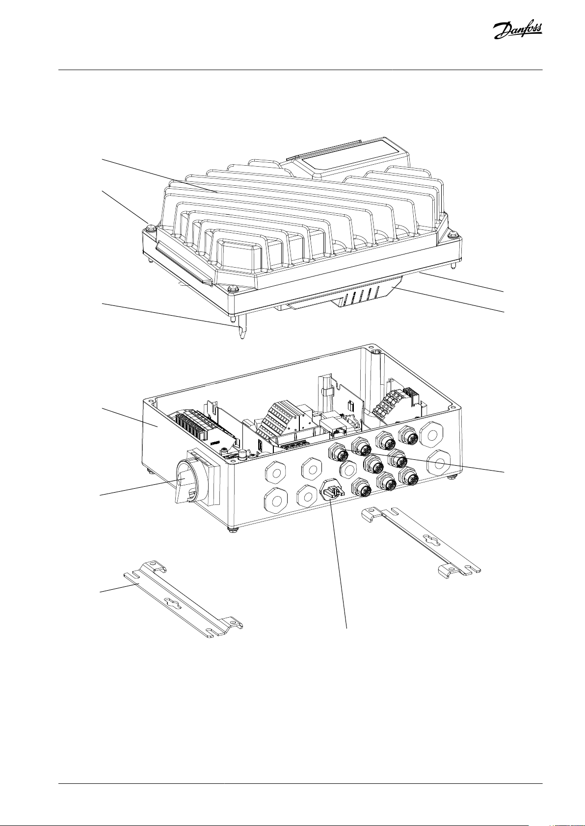
1.4.2 Exploded Views
Introduction
Illustration 1: Exploded View Small Unit
AQ267036816112en-000201 / 130R0208 | 7Danfoss A/S © 2021.09
Page 8

1
Inverter part
2
Fastening screws (4 x, 1 in each corner)
3
Sealing gasket
4
Inverter part plastic cover
5
Ground connection pin
6
Installation box
7
Display connection
8
Access to USB port
9
Service switch-motor side (alternatively, switch located on mains side, or not mounted)
10
Flat mounting brackets
VLT® Decentral Drive FCD 302
Operating Guide
Introduction
AQ267036816112en-000201 / 130R02088 | Danfoss A/S © 2021.09
Page 9
e30bc380.10
1
6
5
9
10
2
3
4
7
8
11
VLT® Decentral Drive FCD 302
Operating Guide
Introduction
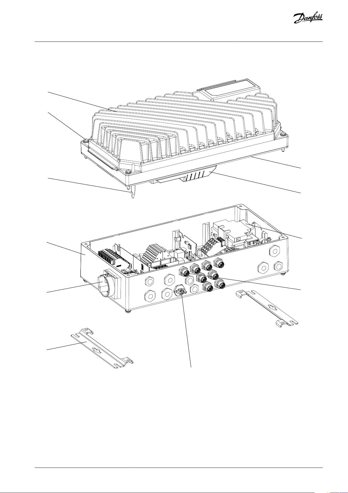
Illustration 2: Exploded View Large Unit
AQ267036816112en-000201 / 130R0208 | 9Danfoss A/S © 2021.09
Page 10
•
•
•
•
•
•
•
•
•
•
•
•
•
•
•
1
Inverter part
2
Fastening screws (4 x, 1 in each corner)
3
Sealing gasket
4
Inverter part plastic cover
5
Ground connection pin
6
Installation box
7
Display connection
8
Access to USB port
9
Service switch
(1)
motor side (alternatively, switch lo-
cated on mains side, or not mounted)
10
Flat mounting brackets
11
Circuit breaker
(1)
(optional)
e75za016.12
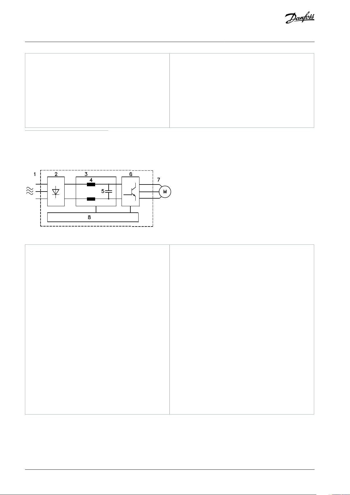
1
Mains input
3-phase AC mains power supply to the drive.
2
Rectifier
The rectifier bridge converts the AC input to DC
current to supply inverter power.
3
DC bus
Intermediate DC-bus circuit handles the DC current.
4
DC reactors
Filter the intermediate DC circuit voltage.
Prove line transient protection.
Reduce RMS current.
Raise the power factor reflected back to the line.
Reduce harmonics on the AC input.
5
Capacitor bank
Stores the DC power.
Proves ride-through protection for short power
losses.
6
Inverter
Converts the DC into a controlled PWM AC
waveform for a controlled variable output to the
motor.
7
Output to motor
Regulated 3-phase output power to the motor.
8
Control circuitry
Input power, internal processing, output, and
motor current are monitored to provide efficient
operation and control.
User interface and external commands are
monitored and performed.
Status output and control can be provided.
VLT® Decentral Drive FCD 302
Operating Guide
1
The unit can be configured with either service switch or circuit breaker, not both. The illustration shown is not configurable in practice, but shows
the respective positions of components only.
Introduction
1.4.3 Block Diagram of the Drive
Illustration 3: Block Diagram
1.5 Type Approvals and Certifications
The following list is a selection of possible type approvals and certifications for Danfoss drives:
AQ267036816112en-000201 / 130R020810 | Danfoss A/S © 2021.09
Page 11
089
VLT® Decentral Drive FCD 302
Operating Guide
Table 2: Type Approvals and Certifications
Introduction
N O T I C E
The specific approvals and certification for the drive are on the nameplate of the drive. For more information, contact the local
Danfoss office or partner.
AQ267036816112en-000201 / 130R0208 | 11Danfoss A/S © 2021.09
Page 12
VLT® Decentral Drive FCD 302
Operating Guide
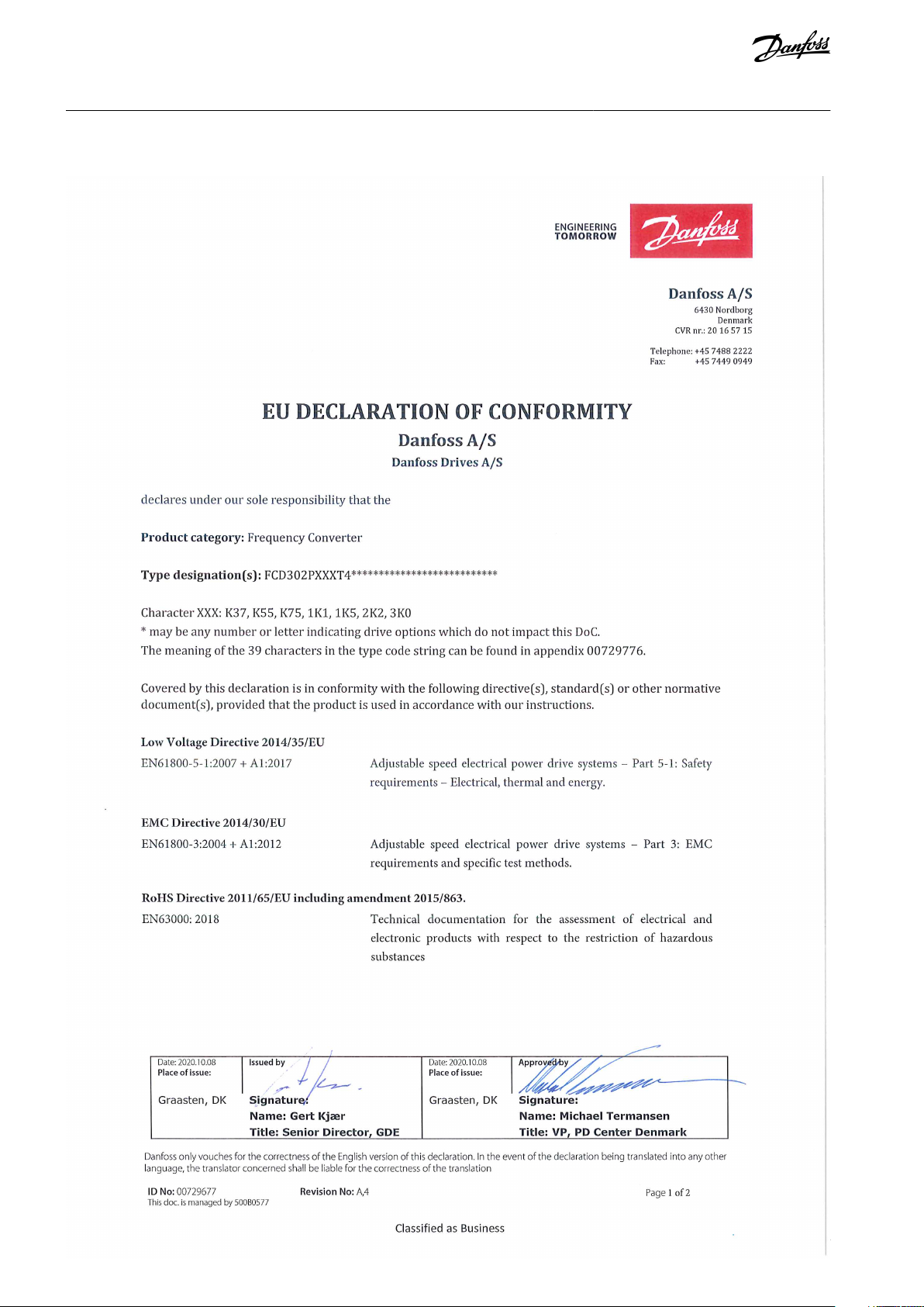
1.6 CE Declaration
Introduction
AQ267036816112en-000201 / 130R020812 | Danfoss A/S © 2021.09
Page 13
VLT® Decentral Drive FCD 302
Operating Guide
Safety
2 Safety
2.1 Safety Precautions
W A R N I N G
HIGH VOLTAGE
AC drives contain high voltage when connected to AC mains input, DC supply, or load sharing. Failure to perform installation,
start-up, and maintenance by qualified personnel can result in death or serious injury.
Only qualified personnel must perform installation, start-up, and maintenance.
-
W A R N I N G
UNINTENDED START
When the drive is connected to the AC mains, the motor may start at any time, causing risk of death, serious injury, and equip-
ment or property damage. The motor may start by activation of an external switch, a fieldbus command, an input reference signal
from the LCP or LOP, via remote operation using MCT 10 Set-up software, or after a cleared fault condition.
Press [Off] on the LCP before programming parameters.
-
Disconnect the drive from the mains whenever personal safety considerations make it necessary to avoid unintended motor
-
start.
Check that the drive, motor, and any driven equipment are in operational readiness.
-
W A R N I N G
DISCHARGE TIME
The drive contains DC-link capacitors, which can remain charged even when the drive is not powered. High voltage can be
present even when the warning indicator lights are off.
Failure to wait the specified time after power has been removed before performing service or repair work could result in death or
serious injury.
Stop the motor.
-
Disconnect AC mains, permanent magnet type motors, and remote DC-link supplies, including battery back-ups, UPS, and
-
DC-link connections to other drives.
Wait for the capacitors to discharge fully. The time for full discharge of the capacitors is minimum 4 minutes for VLT® Decen-
-
tral Drive FCD 302, 400 V AC, 0.37–3.0 kW (0.5–4.0 hp).
Before performing any service or repair work, use an appropriate voltage measuring device to make sure that the capacitors
-
are fully discharged.
C A U T I O N
INTERNAL FAILURE HAZARD
An internal failure in the drive can result in serious injury when the drive is not properly closed.
Ensure that all safety covers are in place and securely fastened before applying power.
-
AQ267036816112en-000201 / 130R0208 | 13Danfoss A/S © 2021.09
Page 14
VLT®
MADE IN DENMARK
P/N: 131Z5118 S/N: 000000G000
1.5kW(400V) / 2.0HP(460V)
IN: 3x380-480V 50/60Hz, 3.7/3.1A
OUT: 3x0-Vin 0-590Hz, 4.1/3.4A
*
1
3
1
Z
5
1
1
8
0
0
0
0
0
0
G
0
0
0
*
Decentral Drive
www.danfoss.com
T/C: FCD302P1K5T4W66H1X1XMFCFXXXXA0BXXXXXXDX
1
2
4
5
6
7
3
IP66 Enclosure Tamb. 40 ˚C/104 ˚F
Enclosure rating:
LISTED E134261 76X1 IND. CONT. EQ.
Type 4X Indoor Use Only
Danfoss A/S
6430 Nordborg
Denmark
8
9
10
e30bf338.11
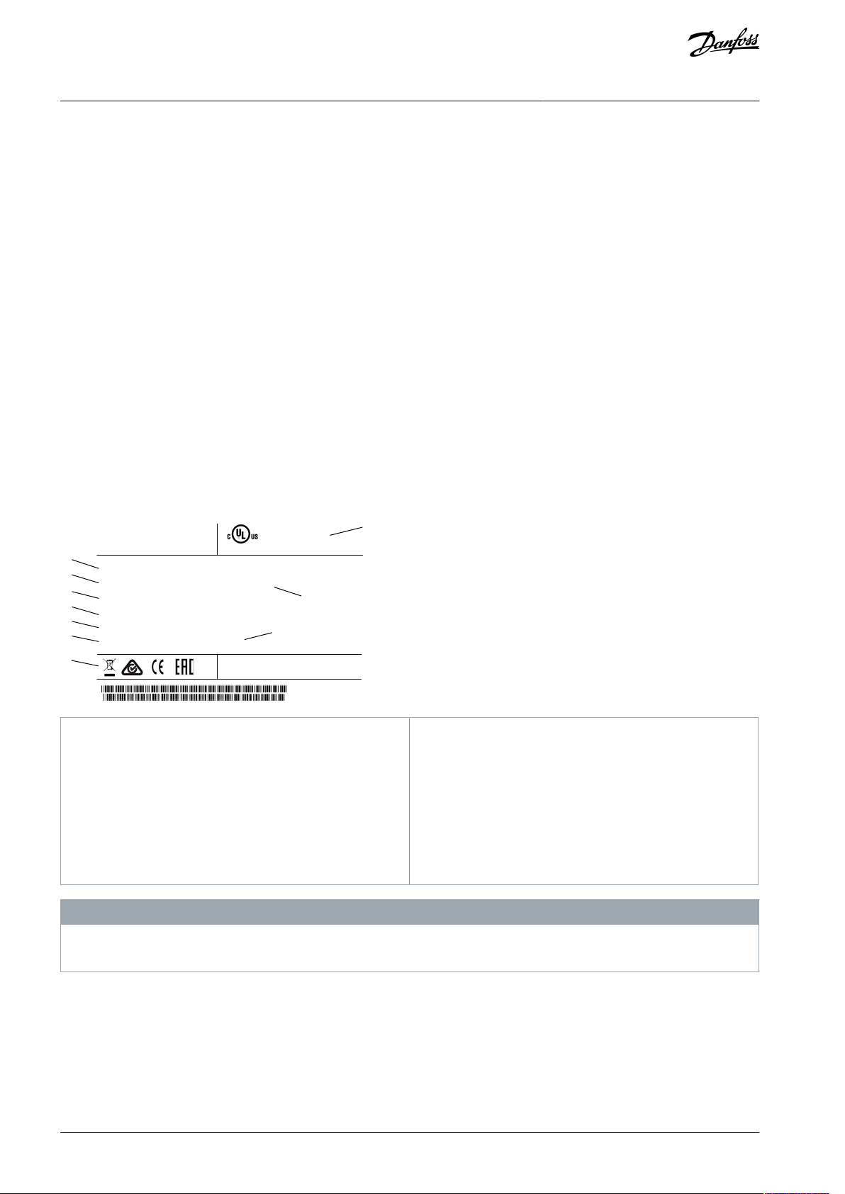
1
Type code
2
Ordering number
3
Serial number
4
Power rating
5
Input voltage, frequency, and current (at low/high
voltages)
6
Output voltage, frequency, and current (at low/high
voltages)
7
Enclosure type and IP rating
8
Maximum ambient temperature
9
Certifications
10
Enclosure rating
VLT® Decentral Drive FCD 302
Operating Guide
Mechanical Installation
3 Mechanical Installation
3.1 Unpacking
3.1.1 Items Supplied
The packaging contains:
•
Accessories bag, supplied only with order of installation box. The bag contains:
-
2 cable clamps.
-
Bracket for motor/loads cables.
-
Elevation bracket for cable clamp.
-
Screw 4 mm, 20 mm.
-
Thread forming 3.5 mm, 8 mm.
•
Operating Guide.
•
Drive.
Depending on options fitted, the box contains 1 or 2 bags and 1 or more booklets.
•
Make sure that the items supplied and the information on the nameplate correspond to the order confirmation.
•
Check the packaging and the drive visually for damage caused by inappropriate handling during shipment. File any claim for
damage with the carrier. Retain damaged parts for clarification.
LOSS OF WARRANTY
Do not remove the nameplate from the drive.
N O T I C E
AQ267036816112en-000201 / 130R020814 | Danfoss A/S © 2021.09
Page 15
100 (4)
100 (4)
100 (4)
100 (4)
e95na261.10
VLT® Decentral Drive FCD 302
Operating Guide
Mechanical Installation
3.1.2 Storage
Ensure that the requirements for storage are fulfilled, see 7.4.1 Environment.
3.2 Installation Environment
N O T I C E
REDUCED LIFETIME
In environments with airborne liquids, particles, or corrosive gases, ensure that the IP/Type rating of the equipment matches the
installation environment. Failure to meet requirements for ambient conditions can reduce lifetime of the drive.
Ensure that requirements for air humidity, temperature, and altitude are met.
-
Vibration and shock
The drive complies with requirements for units mounted on the walls and floors of production premises, and in panels bolted to
walls or floors. For detailed ambient conditions, refer to 7.4.1 Environment.
3.3 Mounting
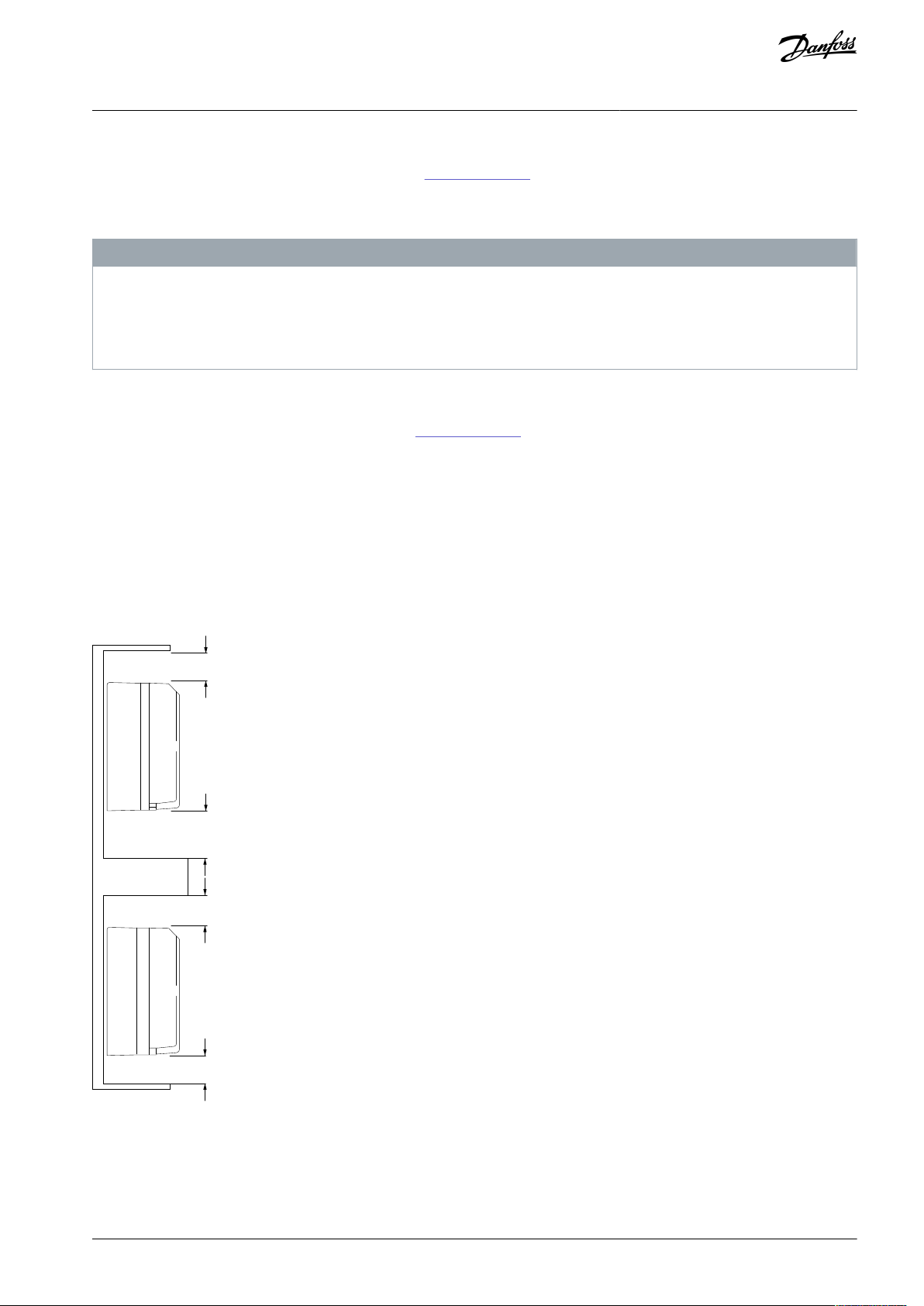
3.3.1 Cooling
The VLT® Decentral DriveFCD 302 has no forced cooling. It relies only on natural convection for cooling using the cooling fins.
•
A minimum of 100 mm (4 in) top and bottom air cooling clearance must be provided.
•
Derating starts above 40 °C (104 °F) and 1000 m (3280 ft) elevation above sea level. See the VLT® Decentral DriveFCD 302 Design
Guide for detailed information.
Illustration 4: Top and Bottom Cooling Clearance
AQ267036816112en-000201 / 130R0208 | 15Danfoss A/S © 2021.09
Page 16
Equipment
Size
Description
Screwdrivers
––Socket (Hex)
8
For fastening inverter screws/mounting of brackets
Slotted
0.4x2.5
For spring loaded power and control terminals
Slotted/Torx
1.0x5.5/TX20
For cable clamps inside the installation box
Spanner
19, 24, 28
For blind-plugs
LCP, ordering number 130B1078
–
Local control panel
LCP cable, ordering number 130B5776
–
Connection cable for local control panel
e30bc382.10
VLT® Decentral Drive FCD 302
Operating Guide
3.3.2 Recommended Tools and Equipment
Table 3: Recommended Tools and Equipment
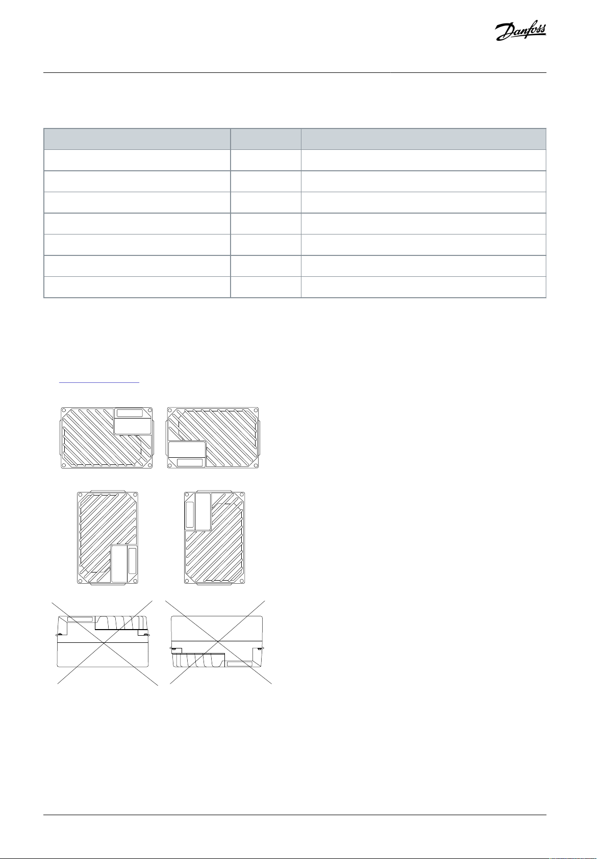
3.3.3 Mounting
The VLT® Decentral DriveFCD 302 consists of 2 parts:
•
Installation box
•
Electronic part
See 1.4.2 Exploded Views.
Mechanical Installation
Illustration 5: Allowed Mounting Positions - Standard Applications
AQ267036816112en-000201 / 130R020816 | Danfoss A/S © 2021.09
Page 17
e30bc383.11
VLT® Decentral Drive FCD 302
Operating Guide
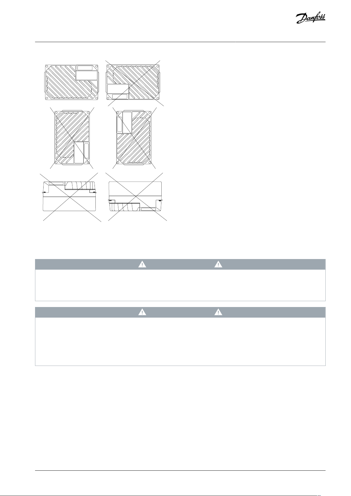
Mechanical Installation
Illustration 6: Allowed Mounting Positions - Hygienic Applications
3.3.3.1 Mounting the Installation Box
W A R N I N G
ELECTRICAL HAZARD
Applying power to the unit at this stage could result in death or serious injury.
Do not apply power before the electrical installation is complete.
-
W A R N I N G
PERSONAL INJURY OR PROPERTY DAMAGE
Do not switch on the mains before the 4 screws are tightened. Failure to tighten these screws can result in personal injury or
material damage when the unit is loaded.
Tighten screws before switching on power.
-
Ensure that the strength of the mounting location can support the unit weight.
-
•
Use the holes on the rear of the installation box to fix mounting brackets.
•
Use proper mounting screws or bolts.
•
For hygienic versions, use cable glands designed to meet hygienic application requirements, for example Rittal HD
2410.110/120/130.
AQ267036816112en-000201 / 130R0208 | 17Danfoss A/S © 2021.09
Page 18

e30bb701.11
VLT® Decentral Drive FCD 302
Operating Guide
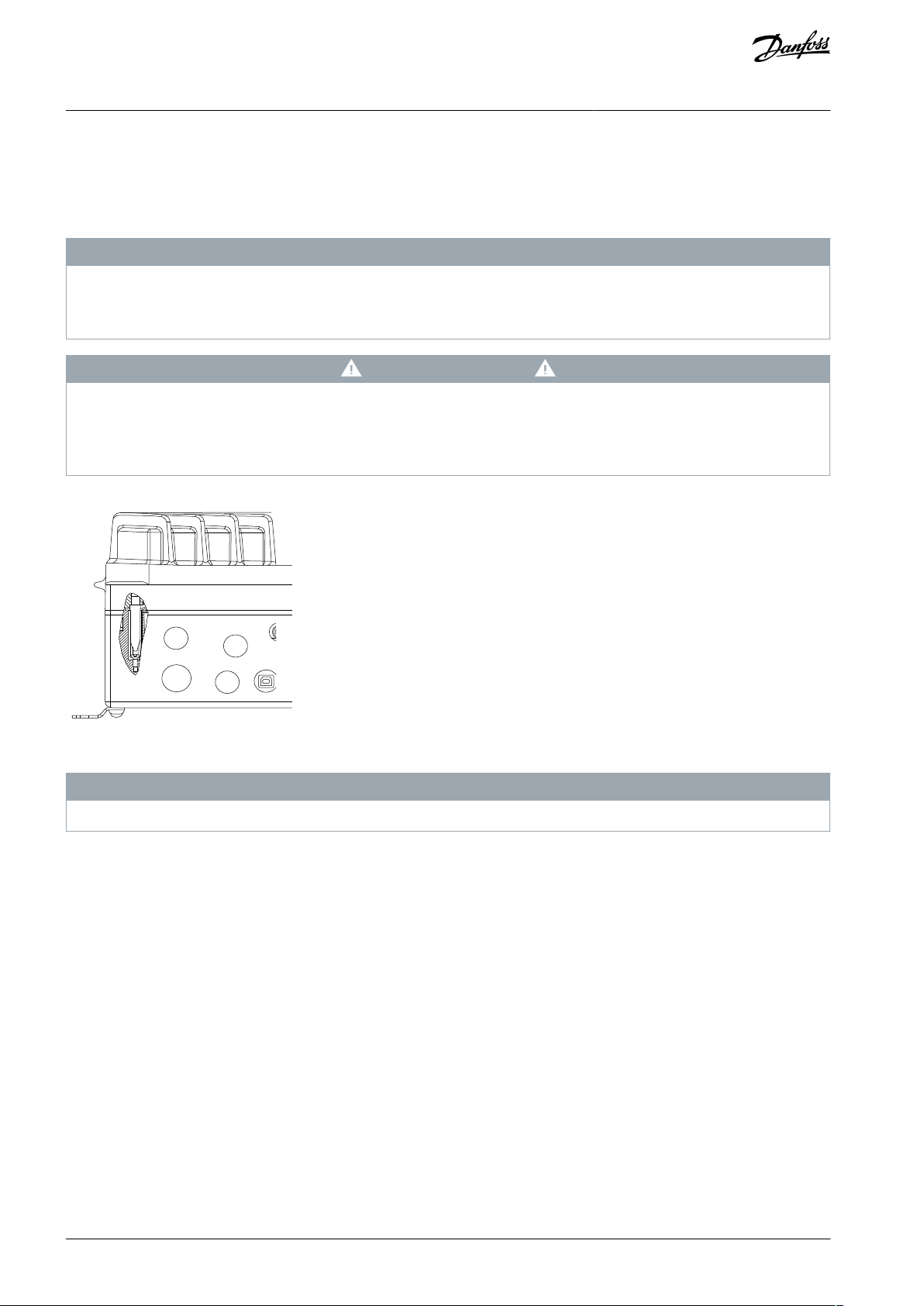
1.
Mount the VLT® Decentral DriveFCD 302 vertically on a wall or machine frame. For hygienic versions ensure that liquids
drain off the enclosure and orient the unit so the cable glands are located at the base.
Example
Mechanical Installation
Illustration 7: FCD 302 Standalone Mounted with Mounting Brackets
3.3.3.2 Installing the Inverter Part
Procedure for compressing the gasket between the 2 parts.
Procedure
1.
Tighten the 4 connection screws to torque 2.8–3.0 Nm (24–26 in-lb).
2.
Tighten the 4 screws in diagonally opposite order.
3.
Tighten the 2 grounding spears to torque 3.0 (26 in-lb).
AQ267036816112en-000201 / 130R020818 | Danfoss A/S © 2021.09
Page 19

VLT® Decentral Drive FCD 302
Operating Guide
Electrical Installation
4 Electrical Installation
4.1 Safety Instructions
See 2.1 Safety Precautions for general safety instructions.
W A R N I N G
INDUCED VOLTAGE
Induced voltage from output motor cables that run together can charge equipment capacitors, even with the equipment turned
off and locked out. Failure to run output motor cables separately or to use shielded cables could result in death or serious injury.
Run output motor cables separately or use shielded cables.
-
Simultaneously lock out all the drives.
-
W A R N I N G
SHOCK HAZARD
The unit can cause a DC current in the PE conductor. Failure to use a Type B residual current-operated protective device (RCD)
may lead to the RCD not providing the intended protection and therefore may result in death or serious injury.
When an RCD is used for protection against electrical shock, only a Type B device is allowed on the supply side.
-
Overcurrent protection
•
Extra protective equipment, such as short-circuit protection or motor thermal protection between drive and motor, is required
for applications with multiple motors.
•
Input fusing is required to provide short circuit and overcurrent protection. If not factory-supplied, the installer must provide
fuses. See maximum fuse ratings in 7.7.2 Recommended Maximum Pre-fuse Size 25 A.
Wire type and ratings
•
All wiring must comply with local and national regulations regarding cross-section and ambient temperature requirements.
•
Power connection wire recommendation: Minimum 75 °C (167 °F) rated copper wire. See 7.1 Electrical Data for recommended
wire sizes and types.
4.2 EMC-compliant Installation
To obtain an EMC-compliant installation, follow the instructions provided in 4.3 Grounding, 4.4 Wiring Schematic, 4.7 Connecting
the Motor, and 4.10.1 Control Wiring.
N O T I C E
POTENTIAL EQUALIZATION
Risk of burst transient when the ground potential between the drive and the control system is different. Install equalizing cables
between the system components. Recommended cable cross-section: 16 mm2 (6 AWG).
4.3 Grounding
For electrical safety
•
Ground the drive in accordance with applicable standards and directives.
•
Use a dedicated ground wire for input power, motor power, and control wiring.
•
Do not ground 1 drive to another in a daisy chain fashion.
•
Keep the ground wire connections as short as possible.
•
Follow motor manufacturer's wiring requirements.
•
Minimum cable cross-section: 10 mm2 (7 AWG) (or 2 rated ground wires terminated separately).
For EMC-compliant installation
AQ267036816112en-000201 / 130R0208 | 19Danfoss A/S © 2021.09
Page 20
e30bc391.10
VLT® Decentral Drive FCD 302
Operating Guide
•
Establish electrical contact between the cable shield and the drive enclosure by using metal cable glands or by using the clamps
provided on the equipment.
•
Use high-strand wire to reduce electrical interference.
•
Do not use pigtails.
Electrical Installation
N O T I C E
POTENTIAL EQUALIZATION
Risk of burst transient when the ground potential between the drive and the control system is different. Install equalizing cables
between the system components. Recommended cable cross-section: 16 mm2 (6 AWG).
C A U T I O N
PE CONNECTION
The metal pins in the corners of the electronic part and the holes on the corner of the installation box are essential for the protec-
tive earth connection. Make sure that they are not loosened, removed, or violated in any way. Tightening torque requirement is
3 Nm (26.6 in-lb).
Illustration 8: PE Connection Between the Installation Box and the Electronic Part
N O T I C E
The external grounding terminal is available as an accessory (ordering number 130B5833).
AQ267036816112en-000201 / 130R020820 | Danfoss A/S © 2021.09
Page 21
e30bc384.11
3-phase
power
input
Mechanical
brake
+10 V DC
-10 V DC+10 V DC
0/4-20 mA
-10 V DC+10 V DC
0/4-20 mA
91 (L1)
92 (L2)
93 (L3)
95 (PE)
122(MBR+)
123(MBR-)
50 (+10 V OUT)
53 (A IN)
54 (A IN)
55 (COM A IN)
12 (+24 V OUT)
13 (+24 V OUT)
18 (D IN)
19 (D IN)
20 (COM D IN)
27 (D IN/OUT)
29 (D IN/OUT)
24V
OV
32 (D IN)
33 (D IN)
37 (D IN)
S201
S202
ON/I=0-20mA
OFF/U=0-10V
P 5-00
24 V (NPN)
0 V (PNP)
24 V (NPN)
0 V (PNP)
24 V (NPN)
0 V (PNP)
24 V (NPN)
0 V (PNP)
24 V (NPN)
0 V (PNP)
24 V (NPN)
0 V (PNP)
Switch mode
power supply
10 V DC
15 mA
24 V DC
600 mA
(U) 96
(U) 97
(W) 98
(PE) 99
Motor
Brake
resistor
(R+) 82
(R-) 81
Relay1
Relay2
03
02
01
06
05
04
240 V AC, 2A
240 V AC, 2A
400 V AC, 2A
Analog output
0/4–20 mA
(COM A OUT) 39
(A OT) 42
ON=Terminated
OFF=Open
S801
S801
GX
(N RS485) 69
(P RS485) 68
5V
RS485
Interface
(COM RS485) 61
(PNP) = Source
(NPN) = Sink
RS485
ON
1 2
ON
1 2
ON
1 2
0 V
VCXA
PROFIBUS
interface
GND1
GND1
RS485
66
63
62
67
GX
VLT® Decentral Drive FCD 302
Operating Guide
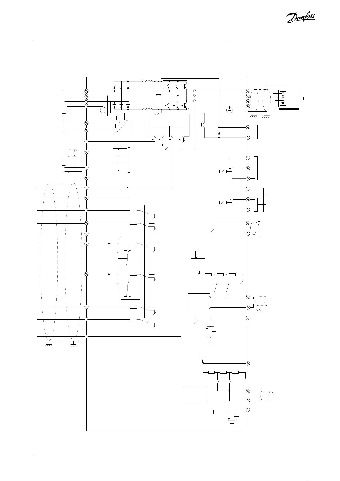
4.4 Wiring Schematic
Electrical Installation
Illustration 9: Basic Wiring Schematic
AQ267036816112en-000201 / 130R0208 | 21Danfoss A/S © 2021.09
Page 22
e30bc286.10
U
96
V
97
W
98
L
1
L
2
L
3
L
1
91
L
2
92
L
3
93
12
27
T
1
T
2
T
3
NO
NC
NO
NC
L
2
L
3
PE
L
1
41
33
5
3
1
2
4
6
34
42
1
2
1
Looping terminals
2
Circuit breaker
L
1
L
2
L
3
PE
U
96
V
97
W
98
L
1
91
L2
92
L3
93
12
27
U
V
W
1
2
3
4
5
6
7
8
1
e30bc287.10
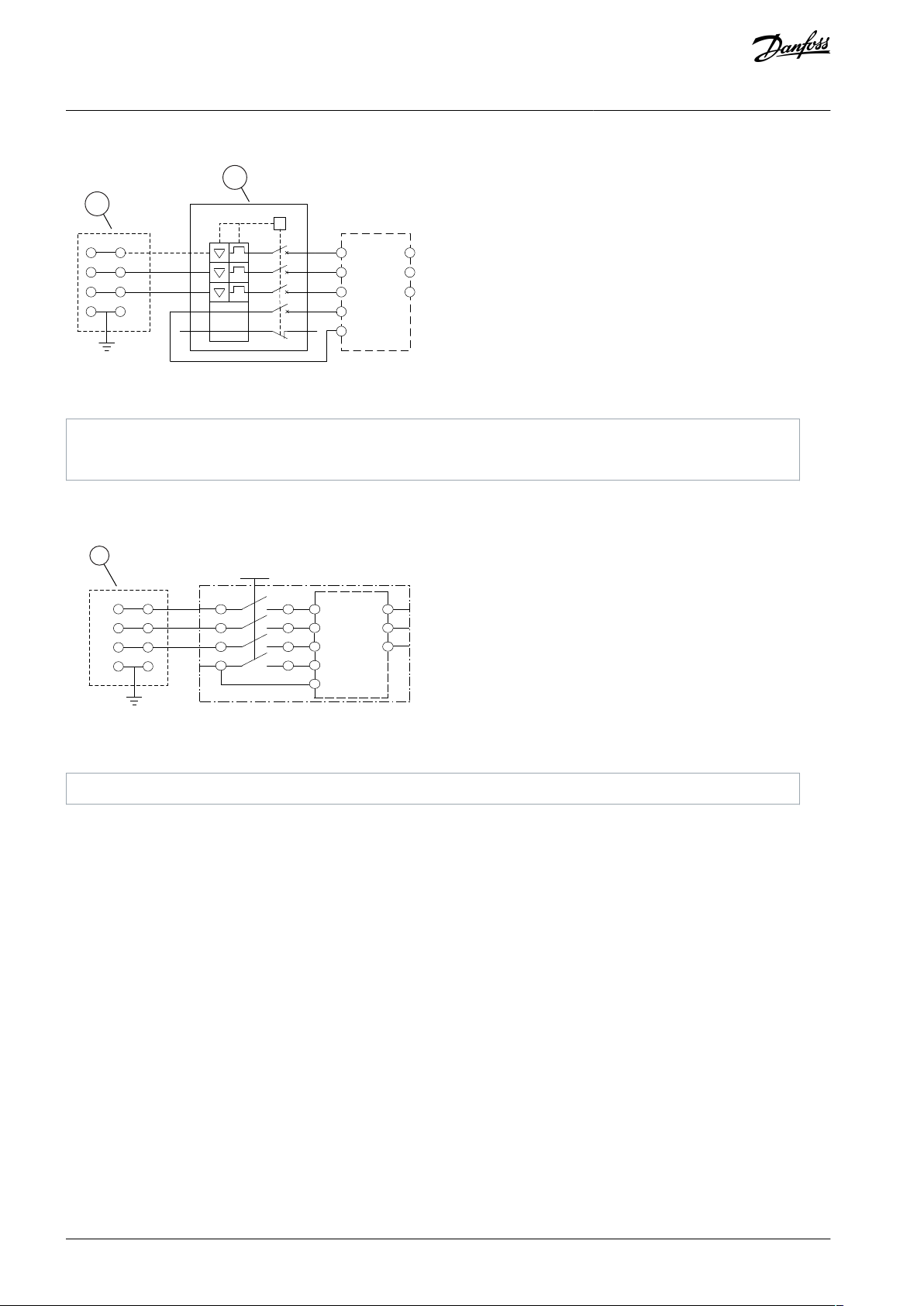
1
Looping terminals
VLT® Decentral Drive FCD 302
Operating Guide
Illustration 10: Large Unit only: Circuit Breaker and Mains Disconnect
Electrical Installation
Illustration 11: Large Unit only: Service Switch at Mains with Looping Terminals
AQ267036816112en-000201 / 130R020822 | Danfoss A/S © 2021.09
Page 23
e30bc385.10
123
4
5
6
7
8
9
10
11
13
13
13
12
L3/93
L1/91
L2/92
8182123
122
U/96
V/97W/98
R
G
V
N
P
B04
B03
B02
B01
B08
B01B06
B05
B12
B11
B10B09
12
18 19 27
29 32 33
12
12
12
12
12
12
13
20
20
20
20 20
20
20
20
20
39
50
54
5355
42
37
37
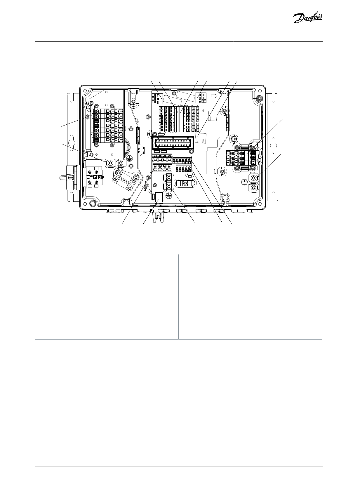
1
Digital and analog inputs/outputs
2
Safe Torque Off (STO), LCP connection, B-option
3
Relay 1
4
Relay 12
5
Motor, mechanical brake, brake resistor
6
Mains
7
24 V DC back-up input
8
USB port
9
Standard bus/RS485
10
PROFIBUS
11
Ethernet port
12
Ethernet port
13
Protective Earth (PE)
VLT® Decentral Drive FCD 302
Operating Guide
4.5 Location of Terminals
Electrical Installation
Illustration 12: Location of Terminals (Small Unit)
AQ267036816112en-000201 / 130R0208 | 23Danfoss A/S © 2021.09
Page 24
e30bc386.10
1
2
3
4
5
13
7
8
9
10
13
6
13
11
12
L3/93 L1/91L2/92
8182123122U/96V/97W/98
R
G
V
N
P
B04
B03
B02B01
B08
B01B06
B05
B12
B11
B10B09
12
18 19 27
29 32 33
12
12
12 12
12
12
13
20
20
20
20 20
20
20
20
20
39
50
54
5355
42
37
37
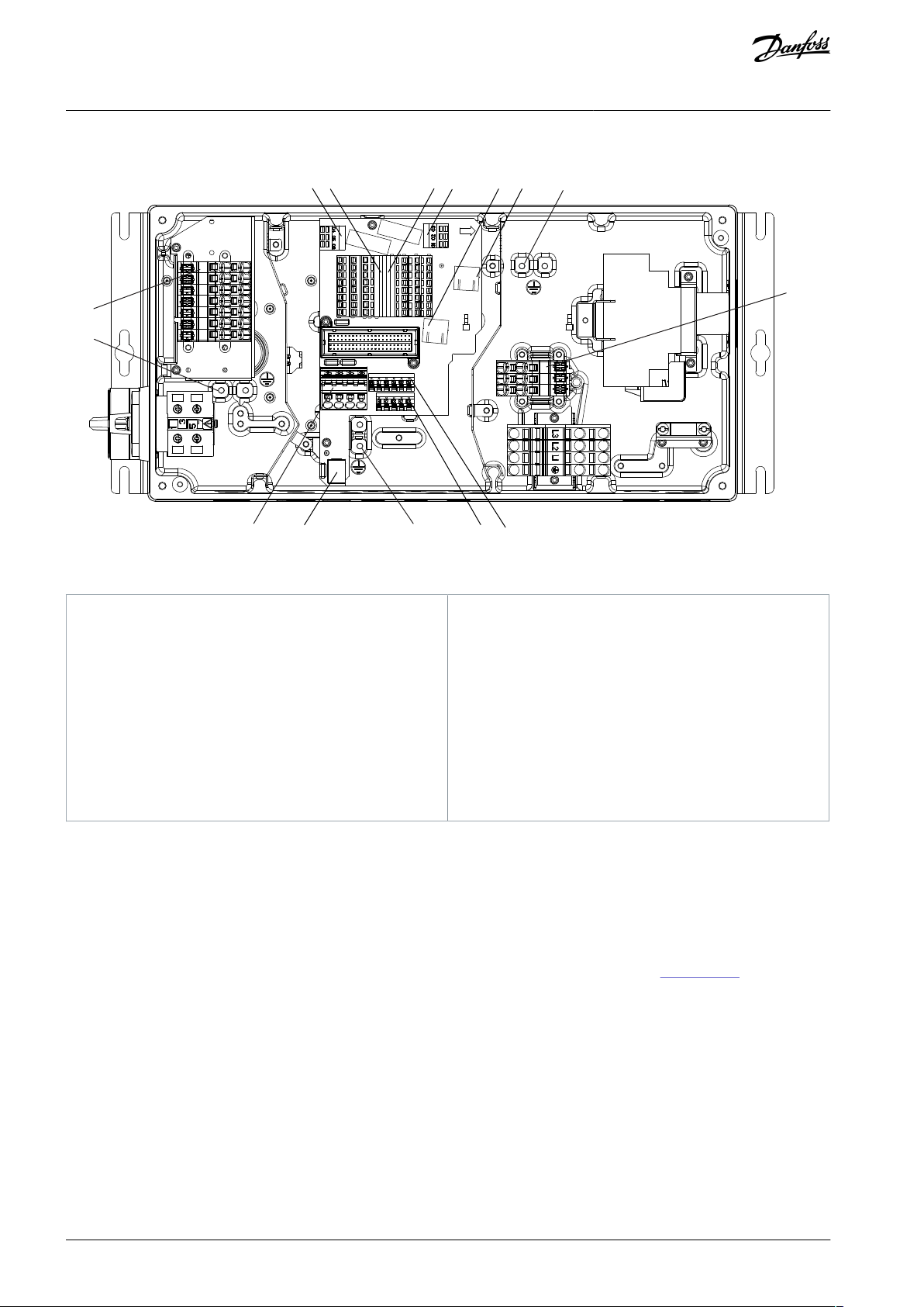
1
Digital and analog inputs/outputs
2
Safe Torque Off (STO), LCP connection, B-option
3
Relay 1
4
Relay 12
5
Motor, mechanical brake, brake resistor
6
Mains
7
24 V DC back-up input
8
USB port
9
Standard bus/RS485
10
PROFIBUS
11
Ethernet port
12
Ethernet port
13
Protective Earth (PE)
VLT® Decentral Drive FCD 302
Operating Guide
Electrical Installation
Illustration 13: Location of Terminals (Large Unit)
For both small and large units, the service switch is optional. The switch is shown mounted on the motor side. Alternatively, the
switch can be on the mains side or omitted.
For the large unit, the circuit breaker is optional. The large unit can be configured with either service switch or circuit breaker, not
both. The illustration shown is not configurable in practice, but shows the respective positions of components only.
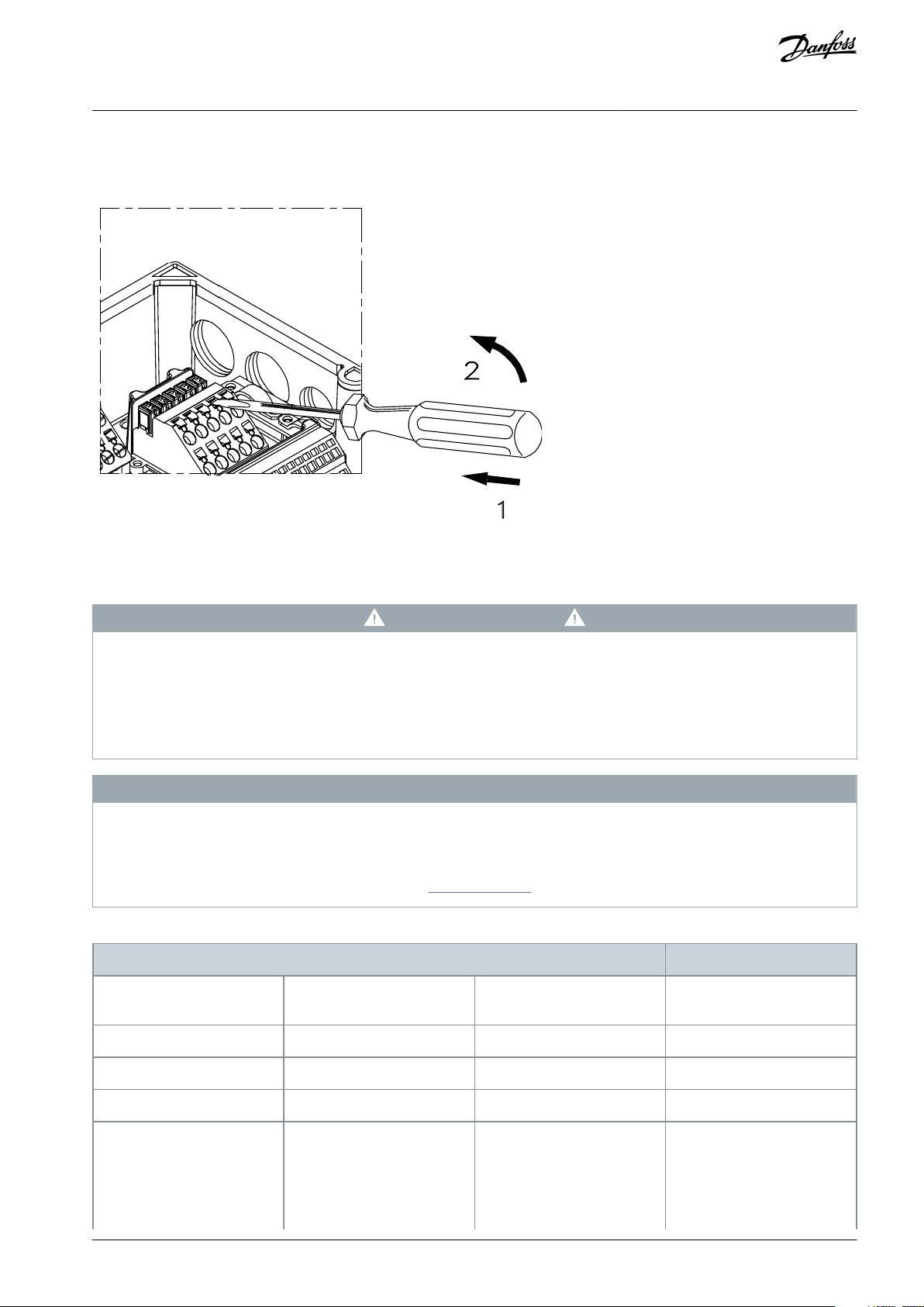
4.6 Terminal Types
Motor, control, and mains terminals are spring loaded (CAGE-CLAMP) type.
1.
Open the contact by inserting a small screwdriver into the slot above the contact, as shown in Illustration 14.
2.
Insert the stripped wire into the contact.
3.
Remove the screwdriver to fasten the wire into the contact.
AQ267036816112en-000201 / 130R020824 | Danfoss A/S © 2021.09
Page 25
e95na248.10
Terminal
969798
Motor voltage 0–100% of
mains voltage
UVW
3 wires out of motor
U1V1W1
6 wires out of motor
W2U2V2
6 wires out of motor
U1V1W1
6 wires out of motor, star connected. Connect U2, V2, W2
VLT® Decentral Drive FCD 302
Operating Guide
4.
Ensure that the contact is firmly established and not loose. Loose wiring can result in equipment faults or injury.
Example
Illustration 14: Opening the Terminals
Electrical Installation
4.7 Connecting the Motor
W A R N I N G
INDUCED VOLTAGE
Induced voltage from output motor cables that run together can charge equipment capacitors, even with the equipment turned
off and locked out. Failure to run output motor cables separately or to use shielded cables could result in death or serious injury.
Run output motor cables separately or use shielded cables.
-
Simultaneously lock out all the drives.
-
N O T I C E
MOTOR PROTECTION
Protection against motor overload is not included in the factory setting. If this function is desired, set parameter 1-90 Motor Ther-
mal Protection to trip or warning. Refer to the VLT® AutomationDrive FC 301/FC 302 Programming Guide for further information.
For correct dimensioning of cable cross-section, see 7.1 Electrical Data.
-
Table 4: Terminals 96, 97, 98
AQ267036816112en-000201 / 130R0208 | 25Danfoss A/S © 2021.09
Page 26

Terminal
separately (optional terminal
block)
PE
Ground connection
e30bc403.10
VLT® Decentral Drive FCD 302
Operating Guide
Electrical Installation
N O T I C E
Do not install power factor correction capacitors between the drive and the motor. Do not wire a starting or pole-changing de-
vice between the drive and the motor.
1.
Connect the motor to terminals 96, 97, 98.
2.
Connect ground to PE terminal.
3.
Make sure that the shield of the motor cable is properly grounded at both ends (motor and drive).
4.7.1 Grounding Shielded Cable
Grounding clamps are provided for motor and control wiring.
Illustration 15: Grounding Clamp for Motor and Control Wiring (Small Unit)
AQ267036816112en-000201 / 130R020826 | Danfoss A/S © 2021.09
Page 27

e30bc390.10
VLT® Decentral Drive FCD 302
Operating Guide
Electrical Installation
Illustration 16: Grounding Clamp for Motor and Control Wiring (Large Unit)
Procedure
1.
Use a wire stripper to remove the insulation for proper grounding.
2.
Secure the grounding clamp to the stripped portion of the wire with the screws provided.
3.
Secure the grounding wire to the grounding clamp provided.
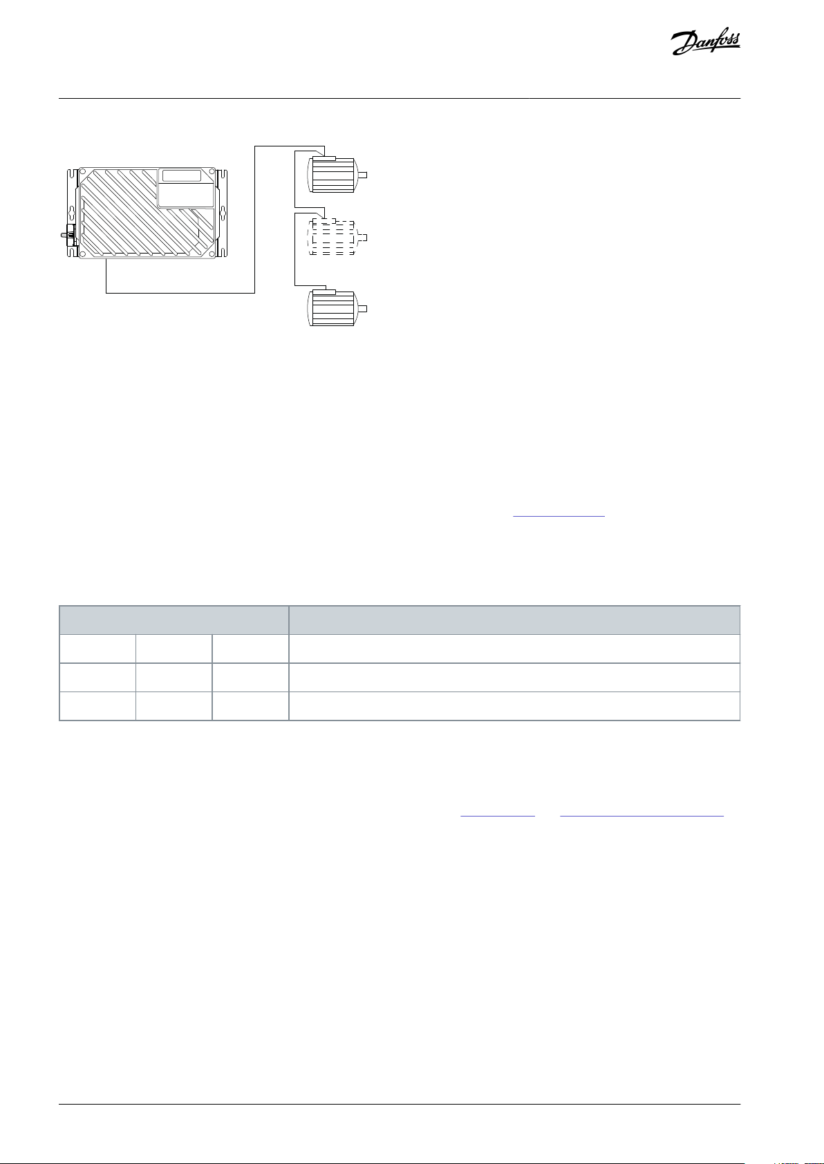
4.7.2 Connecting Several Motors
The drive can control several parallel-connected motors. The total current consumption of the motors must not exceed the rated
output current I
for the drive.
M,N
N O T I C E
Installations with cables connected in a common joint are only recommended for short cable lengths (maximum 10 m (38.2 ft)).
When motors are connected in parallel, parameter 1-29 Automatic Motor Adaptation (AMA) cannot be used.
N O T I C E
The electronic thermal relay (ETR) of the drive cannot be used as motor protection for the individual motor in systems with paral-
lel-connected motors. Provide further motor protection by thermistors in each motor or individual thermal relays. Circuit breakers
are not suitable as protection.
AQ267036816112en-000201 / 130R0208 | 27Danfoss A/S © 2021.09
Page 28
e30bb706.11
Terminals
919293
Mains voltage 3x380–480 V
L1L2L3PEGround connection
VLT® Decentral Drive FCD 302
Operating Guide
Illustration 17: Parallel Connection of Motors
Problems can arise at start-up and at low RPM values when motor sizes differ widely. Motors of low rated motor power have a relatively high ohmic resistance in the stator. This high resistance calls for a higher voltage at start and at low RPM values. To resolve
such a problem:
•
Reduce the load during start-up on the motor of lowest rated motor power.
•
Configure parallel connections only between motors of comparable rated motor power.
Electrical Installation
4.8 Connecting AC Mains
•
Size the wiring based on the input current of the drive. For maximum wire sizes, see 7.1 Electrical Data.
•
Comply with local and national electrical codes for cable sizes.
4.8.1 Connecting the Drive to Mains
Table 5: Terminals 91, 92, and 93
Procedure
1.
Connect the 3-phase AC input power wiring to terminals L1, L2, and L3.
2.
Depending on the configuration of the equipment, connect the input power to the mains input terminals or the input disconnect.
3.
Ground the cable in accordance with the grounding instructions, see 4.3 Grounding and 4.7.1 Grounding Shielded Cable.
4.
When supplied from an isolated mains source (IT mains or floating delta) or TT/TN-S mains with a grounded leg (grounded
delta), ensure that parameter 14-50 RFI Filter is set to [0] Off. This setting prevents damage to the DC link and reduces
ground capacity currents in accordance with IEC 61800-3.
AQ267036816112en-000201 / 130R020828 | Danfoss A/S © 2021.09
Page 29

e95na288.10
Terminal
Number
Functions
01, 02, 03
Relay 1 output. Usable for AC or DC voltage and resistive or inductive loads.
04, 05, 06
Relay 2 output. Usable for AC or DC voltage and resistive or inductive loads.
12, 13
24 V DC digital supply voltage. Useable for digital inputs and external transducers. To use the 24 V DC for digital
input common, programme parameter 5-00 Digital I/O Mode for PNP operation.
18, 19, 32, 33
Digital inputs. Selectable for NPN or PNP function in parameter 5-00 Digital I/O Mode. Default is PNP.
VLT® Decentral Drive FCD 302
Operating Guide
4.9 Motor and Mains Connection with Service Switch
Illustration 18: Motor and Mains Connection with Service Switch
Electrical Installation
4.10 Control Terminals
4.10.1 Control Wiring
W A R N I N G
UNINTENDED START
When the drive is connected to the AC mains, DC supply, or load sharing, the motor may start at any time, causing risk of death,
serious injury, and equipment or property damage. The motor may start by activation of an external switch, a fieldbus command,
an input reference signal from the LCP or LOP, via remote operation using MCT 10 Set-up software, or after a cleared fault condi-
tion.
Press [Off] on the LCP before programming parameters.
-
Disconnect the drive from the mains whenever personal safety considerations make it necessary to avoid unintended motor
-
start.
Check that the drive, motor, and any driven equipment are in operational readiness.
-
•
It is recommended that control wiring is rated for 600 V.
•
Isolate control wiring from high-power components in the drive.
•
If the drive is connected to a thermistor, for PELV isolation, ensure that control wiring is reinforced/double insulated.
4.10.2 Terminal Functions
Table 6: Terminal Functions
AQ267036816112en-000201 / 130R0208 | 29Danfoss A/S © 2021.09
Page 30

Terminal
Number
Functions
27, 29
Digital inputs or outputs. Program parameter 5-01 Terminal 27 Mode for terminal 27 and parameter 5-02 Terminal
29 Mode for terminal 29 for selecting the input/output functions. Default setting is input.
35
Common (-) for external 24 V control back-up supply. Optional.
36
External + 24 V control back up supply. Optional.
37
Safe Stop.
20
Common for digital inputs. To use for digital input common, programme parameter 5-00 Digital I/O Mode for
NPN operation.
39
Common for analog output.
42
Analog output. Programmable for various functions in parameter group 6-5* Analog Output 1. The analog signal
is 0–20 mA or 4–20 mA at a maximum of 500 Ω.
50
10 V DC analog supply voltage. 15 mA maximum commonly used for a potentiometer or thermistor.
53, 54
Analog input. Selectable for voltage (0 to ±10 V) or current (0 or 4 to ± 20 mA). Closed is for current and open is
for voltage. Switches are located on the drive control card.
See 4.10.6 DIP Switches.
55
Common for analog inputs.
61
Common for serial communication (RS485 interface).
See 4.3 Grounding.
68 (+), 69 (-)
RS485 interface. When the drive is connected to an RS485 serial communication bus, a switch on the control
card is provided for termination resistance. Set the switch to ON for termination and OFF for no termination.
62
RxD/TxD –P (red cable) for PROFIBUS. See dedicated literature for VLT® PROFIBUS DP V1 MCA 101) for details.
63
RxD/TxD –N (green cable) for PROFIBUS.
66
0 V for PROFIBUS.
67
+5 V for PROFIBUS.
B01-B12
B-option. See dedicated literature for details.
G, R, V, N, P
Connection of LCP.
Terminal
Function
81 (optional function)
R-
Brake resistor terminals
82 (optional function)
R+
VLT® Decentral Drive FCD 302
Operating Guide
Electrical Installation
4.10.3 Brake Resistor
Table 7: Brake Resistor Terminals
•
The connection cable to the brake resistor must be shielded/armored. Connect the shield to the metal cabinet of the drive and
to the metal cabinet of the brake resistor with cable clamps.
•
Dimension the cross-section of the brake cable to match the brake torque.
AQ267036816112en-000201 / 130R020830 | Danfoss A/S © 2021.09
Page 31

•
•
Number
Function
122 (optional function)
MBR+
Mechanical brake
UDC = 0.45 x RMS mains
voltage
Maximum current = 0.8 A
123 (optional function)
MBR-
Pin
Wire color
Terminal
Function
1
Brown
12
+24 V
3
Blue200 V4Black
18, 19, 32, 33
Digital input
Pin
Wire color
Terminal
Function
1
Brown
Reserved
(1)
Reserved
3
Blue200 V4Black
02, 05
N.O. (24 V)
VLT® Decentral Drive FCD 302
Operating Guide
Electrical Installation
4.10.4 Mechanical Brake
Table 8: Terminals 122 and 123
In hoisting/lowering applications, control of electro-mechanical brake is required:
•
The brake is controlled using the special mechanical brake control/supply terminals 122 and 123.
•
Select [32] Mechanical brake control in parameter group 5-4* Relays, [1] Array, Relay 2 for applications with an electro-mechanical
brake.
•
The brake is released when the motor current exceeds the preset value in parameter 2-20 Release Brake Current.
•
The brake is engaged when the output frequency is less than the frequency set in parameter 2-21 Activate Brake Speed [RPM] or
parameter 2-22 Activate Brake Speed [Hz]. The brake engages only when the drive performs a stop command.
When the drive enters alarm mode or is exposed to an overvoltage situation, the mechanical brake immediately cuts in. For more
detailed information, refer to the VLT® AutomationDrive FC 301/FC 302 Programming Guide.
N O T I C E
When the mechanical brake control/supply terminals 122 and 123 are set through parameter group 5–4* Relays, [1] Array , Relay 2,
only 1 relay output (Relay 1) is available for free programming.
4.10.5 Connection of Sensors/Actuators on M12 Sockets
Table 9: 4 x M12 Connection Input
Table 10: 2 x M12 Connection Output
1
When reserved wires for option are used. If not utilized, they can be cut off.
AQ267036816112en-000201 / 130R0208 | 31Danfoss A/S © 2021.09
Page 32

e30bc389.10
1
2
3
4
1
2
3
4
1
2
3
4
1
2
3
4
1
2
3
4
1
2
3
4
1
2
3
4
LCP
RL2
RL1
33
USB
3219
FB2 FB1
18
1
2
3
4
1
2
3
4
e30bb708.10
1 2
4
3
5
1
S201 - terminal 53
2
S202 - terminal 54
3
S801 - standard bus termination
4
PROFIBUS termination
5
Fieldbus address
VLT® Decentral Drive FCD 302
Operating Guide
Illustration 19: Connection of Sensors/Actuators on M12 Sockets
4.10.6 DIP Switches
•
Analog input terminals 53 and 54 can select either voltage (0-10 V) or current (0-20 mA) input signals.
•
Set switches S201 (terminal 53) and S202 (terminal 54) to select the signal type. ON is for current, OFF for voltage.
•
Terminal 53 default is for a speed reference in open loop.
•
Terminal 54 default is for a feedback signal in closed loop.
Electrical Installation
Illustration 20: Location of DIP Switches
N O T I C E
Switches 4 and 5 are only valid for units fitted with fieldbus options.
Refer to VLT® PROFIBUS DP V1 MCA 101 Programming Guide for further information.
AQ267036816112en-000201 / 130R020832 | Danfoss A/S © 2021.09
4.10.7 Safe Torque Off (STO)
To run STO, additional wiring for the drive is required.
Refer to the VLT® Frequency Converters Safe Torque Off Operating Guide for further information.
4.10.8 RS485 Serial Communication
•
Use shielded serial communication cable.
•
See 4.3 Grounding for proper grounding.
Page 33

•
•
•
•
•
•
61
68
69
+
e30bb489.10
RS485
Inspect for
Description
☑
Auxiliary equipment
Look for auxiliary equipment, switches, disconnects, or input fuses/circuit breakers located on the
input power side of the drive, or the output side to the motor. Examine their operational readiness and ensure that they are ready in all respects for operation at full speed.
Check function and installation of any sensors used for feedback to the drive.
Remove power factor correction caps on motor(s), if present.
Cable routing
Ensure that input power, motor wiring and control wiring are separated or in 3 separate metallic conduits for high-frequency noise isolation.
Control wiring
Check for broken or damaged wires and connections.
Check the voltage source of the signals, if necessary.
The use of shielded cable or twisted pair is recommended. Ensure that the shield is terminated
correctly at both ends.
VLT® Decentral Drive FCD 302
Operating Guide
•
2 communication protocols are internal to the drive:
-
Danfoss FC.
-
Modbus RTU.
•
Functions can be programmed remotely using the protocol software and RS485 connection or in parameter group 8-** Commu-
Electrical Installation
nications and Options.
Selecting a specific communication protocol changes various default parameter settings to match the specifications of that pro-
•
tocol and makes more protocol-specific parameters available.
Option cards for the drive are available to provide extra communication protocols. See the option card documentation for in-
•
stallation and operating guides.
4.10.8.1 Connecting and Setting Up RS485
Procedure
Connect RS485 serial communication wiring to terminals (+)68 and (-)69.
1.
Illustration 21: Serial Communication Wiring Diagram
2.
Select the protocol type in parameter 8-30 Protocol.
3.
Set the drive address in parameter 8-31 Address.
4.
Set the baud rate in parameter 8-32 Baud Rate.
4.11 Installation Checklist
Before completing installation of the unit, inspect the entire installation as detailed in
completed.
Table 11: Start-up Checklist
Table 11. Check and mark the items when
AQ267036816112en-000201 / 130R0208 | 33Danfoss A/S © 2021.09
Page 34

•
•
Inspect for
Description
☑
EMC considerations
Check for proper installation regarding electromagnetic compatibility.
Environmental
considerations
See the equipment label for the maximum ambient operating temperature limits. Temperature is not
to exceed 40°C (104°F). Humidity levels must be 5-95% non-condensing.
Cooling clearance
Units require top and bottom clearance adequate to ensure proper air flow for cooling.
Fusing and circuit
breakers
Check that all fuses are inserted firmly and in operational condition and that all circuit breakers are in
the open position. Check for proper fusing or circuit breakers.
Input and output
power wiring
Check for loose connections.
Check for proper fusing or circuit breakers.
Switches
Ensure that all switch and disconnect settings are in the proper position.
Grounding
The equipment requires a dedicated ground wire from its chassis to the plant ground. Check for good
ground connections that are tight and free of oxidation.
Installation box
and electronics
part
Ensure the installation box and the electronics part is properly closed. Check that all 4 fastening
screws are tightened with the right torque.
Cable glands and
blind plugs
Ensure the cable glands and blind plugs are properly tightened to guarantee that the right enclosure
protection degree is achieved. Liquids and/or excessive dust ingress in the drive can cause sub-optimal performance or damage.
Vibration
Ensure the equipment is not exposed to a high level of vibration. Mount the panel solidly or use shock
mounts as necessary.
VLT® Decentral Drive FCD 302
Operating Guide
Electrical Installation
C A U T I O N
INTERNAL FAILURE HAZARD
An internal failure in the drive can result in serious injury when the drive is not properly closed.
Ensure that all safety covers are in place and securely fastened before applying power.
-
AQ267036816112en-000201 / 130R020834 | Danfoss A/S © 2021.09
Page 35

VLT® Decentral Drive FCD 302
Operating Guide
Commissioning
5 Commissioning
5.1 Safety Instructions
See 2.1 Safety Precautions for general safety instuctions.
W A R N I N G
HIGH VOLTAGE
AC drives contain high voltage when connected to AC mains input, DC supply, or load sharing. Failure to perform installation,
start-up, and maintenance by qualified personnel can result in death or serious injury.
Only qualified personnel must perform installation, start-up, and maintenance.
-
5.1.1 Before Applying Power
Procedure
1.
Close the safety cover properly.
2.
Check that all cable glands are firmly tightened.
3.
Ensure that input power to the unit is off and locked out. Do no rely on the drive disconnect switches for input power
isolation.
4.
Verify that there is no voltage on input terminals L1 (91), L2 (92), and L3 (93), phase-to-phase, and phase-to-ground.
5.
Verify that there is no voltage on output terminals 96 (U), 97 (V), and 98 (W), phase-to-phase, and phase-to-ground.
6.
Confirm continuity of the motor by measuring Ω values on U–V (96–97), V–W (97–98), and W–U (98–96).
7.
Check for proper grounding of the drive and the motor.
8.
Inspect the drive for loose connections on the terminals.
9.
Confirm that the supply voltage matches the voltage of the drive and the motor.
5.2 Applying Power
W A R N I N G
UNINTENDED START
When the drive is connected to the AC mains, DC supply, or load sharing, the motor may start at any time, causing risk of death,
serious injury, and equipment or property damage. The motor may start by activation of an external switch, a fieldbus command,
an input reference signal from the LCP or LOP, via remote operation using MCT 10 Set-up software, or after a cleared fault condi-
tion.
Press [Off] on the LCP before programming parameters.
-
Disconnect the drive from the mains whenever personal safety considerations make it necessary to avoid unintended motor
-
start.
Check that the drive, motor, and any driven equipment are in operational readiness.
-
Procedure
1.
Confirm that the input voltage is balanced within 3%. If not, correct the input voltage imbalance before proceeding. Repeat
this procedure after the voltage correction.
2.
Ensure that any optional equipment wiring matches the installation application.
3.
Ensure that all operator devices are in the OFF position. Panel doors must be closed and covers securely fastened.
4.
Apply power to the unit. Do not start the drive now. For units with a disconnect switch, turn it to the ON position to apply
power to the drive.
AQ267036816112en-000201 / 130R0208 | 35Danfoss A/S © 2021.09
Page 36

e30bd598.10
Auto
On
Reset
Hand
On
Off
Status
Quick
Menu
Main
Menu
Alarm
Log
Back
Cancel
Info
OK
Status
1(1)
36.4 kW
Auto Remote Ramping
0.000
On
Alarm
Warn.
A
7.83 A
799 RPM
B
C
D
53.2 %
1
2
3
4
5
6
7
8
9
10
11
12
13
14
15
16
17
18
19 20 21
VLT® Decentral Drive FCD 302
Operating Guide
Commissioning
5.3 Local Control Panel Operation
5.3.1 Local Control Panel
The local control panel (LCP) is the combined display and keypad on the front of the unit.
LCP functions
•
Control drive speed in hand-on mode.
•
Start, stop, and control speed when in local control.
•
Show operational data, status, warnings, and cautions.
•
Program drive functions.
•
Manually reset the drive after a fault when auto reset is inactive.
An optional numeric LCP (NLCP) is also available. The NLCP operates in a manner similar to the LCP. See the product-relevant Programming Guide for details on use of the NLCP.
N O T I C E
For commissioning via PC, install the MCT 10 Set-up Software. The software is available for download (basic version) or for order-
ing (advanced version, code number 130B1000). For more information and downloads, see www.danfoss.com.
5.3.2 LCP Layout
The LCP is divided into 4 functional groups:
•
A: Display area
•
B: Display menus and keys
•
C: Navigation keys and indicator lights (LEDs)
•
D: Operation keys and reset
Illustration 22: Local Control Panel (LCP)
AQ267036816112en-000201 / 130R020836 | Danfoss A/S © 2021.09
Page 37

Callout
Parameter
Default setting
1
Parameter 0-20 Display Line 1.1 Small
[1617] Speed [RPM]
2
Parameter 0-21 Display Line 1.2 Small
[1614] Motor Current
3
Parameter 0-22 Display Line 1.3 Small
[1610] Power [kW]
4
Parameter 0-23 Display Line 2 Large
[1613] Frequency
5
Parameter 0-24 Display Line 3 Large
[1602] Reference %
Callout
Key
Function
6
Status
Shows operational information.
7
Quick Menu
Allows access to programming parameters for initial setup instructions and many detailed application
instructions.
8
Main Menu
Allows access to all programming parameters.
9
Alarm Log
Shows a list of current warnings, the last 10 alarms, and the maintenance log.
Callout
Key
Function
10
Back
Reverts to the previous step or list in the menu structure.
11
Cancel
Cancels the last change or command as long as the display mode has not changed.
12
Info
Press for a definition of the function being shown.
13
Navigation keys
Press to move between items in the menu.
14OKPress to access parameter groups or to enable a choice.
Callout
Indicator
Light
Function
15ONGreen
The ON light activates when the drive receives power from mains voltage, a DC bus terminal, or
an external 24 V DC supply.
16
WARN
Yellow
When warning conditions are met, the yellow WARN light comes on and text appears in the display area identifying the problem.
17
ALARM
Red
A fault condition causes the red alarm light to flash and an alarm text is shown.
VLT® Decentral Drive FCD 302
Operating Guide
Commissioning
Area A: Display area
The display area is activated when the drive receives power from mains voltage, a DC bus terminal, or an external 24 V DC supply.
The information shown on the LCP can be customized for user application. Select options in the Quick Menu Q3-13 Display Settings.
Table 12: Legend to Area A, Display Area
Area B: Display menu keys
Menu keys are used for menu access for parameter set-up, toggling through status display modes during normal operation, and
viewing fault log data.
Table 13: Legend to Area B, Display Menu Keys
Area C: Navigation keys and indicator lights (LEDs)
Navigation keys are used for programming functions and moving the display cursor. The navigation keys also provide speed control
in local (hand) operation. There are also 3 drive status indicator lights in this area.
Table 14: Legend to Area C, Navigation Keys
Table 15: Legend to Area C, Indicator Lights (LEDs)
AQ267036816112en-000201 / 130R0208 | 37Danfoss A/S © 2021.09
Page 38

•
•
Callout
Key
Function
18
Hand On
Starts the drive in local control.
An external stop signal by control input or serial communication overrides the local control.
19
Off
Stops the motor but does not remove power to the drive.
20
Auto On
Puts the system in remote control.
Responds to an exteral start command by control terminals or serial communication.
21
Reset
Resets the drive manually after a fault has been cleared.
VLT® Decentral Drive FCD 302
Operating Guide
Area D: Operation keys and reset
Operation keys are a the bottom of the LCP.
Table 16: Legend to Area D, Operation Keys and Reset
Commissioning
N O T I C E
The display contrast can be adjusted by pressing [Status] and[▵]/[▿] keys.
5.3.3 Parameter Settings
Establishing the correct programming for applications often requires setting functions in several related parameters.
Programming data are stored internally in the drive.
•
For back-up, upload data into the LCP memory.
•
To download data to another drive, connect the LCP to that unit and download the stored settings.
•
Restoring factory default settings does not change data stored in the LCP memory.
5.3.4 Uploading/Downloading Data to/from the LCP
Procedure
1.
Press [Off] to stop the motor before uploading or downloading data.
2.
Press [Main Menu].
3.
Go to parameter 0-50 LCP Copy and press [OK].
4.
Select [1] All to LCP to upload data to the LCP, or select [2] All from LCP to download data from the LCP.
5.
Press [OK].
A progress bar shows the uploading or downloading process.
6.
Press [Hand On] or [Auto On] to return to normal operation.
5.3.5 Changing Parameter Settings
Parameter settings can be accessed and changed via the [Quick Menu] or [Main Menu] keys. The Quick Menu only gives access to a
limited number of parameters.
Procedure
Press [Quick Menu] or [Main Menu] on the LCP.
1.
Press [▵]/[▿] to browse through the parameter groups, press [OK] to select a parameter group.
2.
Press [▵]/[▿] to browse through the parameters, press [OK] to select a parameter.
3.
Press [▵]/[▿] to change the value of a parameter setting.
4.
Press [◃]/[▹] to shift digit when a decimal parameter is in the editing state.
5.
Press [OK] to accept the change.
6.
7.
Press either [Back] twice to enter Status, or press [Main Menu] once to enter Main Menu.
AQ267036816112en-000201 / 130R020838 | Danfoss A/S © 2021.09
Page 39

VLT® Decentral Drive FCD 302
Operating Guide
Commissioning
5.3.6 Restoring Default Settings
N O T I C E
RISK OF LOSING DATA
When restoring default settings, there is a risk of losing programming, motor data, localization, and monitoring records.
Provide a back-up by uploading data to the LCP before initialization.
-
Restoring the default parameter settings is done by initialization of the drive. Initialization is carried out via parameter 14-22 Opera-
tion Mode (recommended) or manually.
•
Initialization via parameter 14-22 Operation Mode does not reset the drive settings such as hours run, serial communication selections, personal menu settings, fault log, alarm log, and other monitoring functions.
Manual initialization erases all motor programming, localization, and monitoring data, and restores factory default settings.
•
5.3.6.1 Recommended Initialization
Procedure
Press [Main Menu] twice to access parameter.
1.
2.
Scroll to parameter 14-22 Operation Mode and press [OK].
3.
Scroll to [2] Initialisation and press [OK].
4.
Remove power to the unit and wait for the display to turn off.
Apply power to the unit.
5.
Default parameter settings are restored during start-up. This may take slightly longer than normal.
6.
Alarm 80, Drive initialised is shown.
Press [Reset] to return to operating mode.
7.
5.3.6.2 Manual Initialization
Procedure
Remove power to the unit and wait for the display to turn off.
1.
Press and hold [Status], [Main Menu], and [OK] at the same time while applying power to the unit (approximately 5 s or until
2.
a click is heard and the fan starts).
Factory default parameter settings are restored during start-up. This might take slightly longer than normal.
Manual initialization resets parameter settings except for the settings in:
•
Parameter 15-00 Operating Hours.
•
Parameter 15-03 Power Up's.
•
Parameter 15-04 Over Temp's.
•
Parameter 15-05 Over Volt's.
5.4 Basic Operational Programming
Drives require basic operational programming before running for best performance. Basic operational programming requires entering motor nameplate data for the motor being operated and the minimum and maximum motor speeds. Enter the data in accordance with the following procedure. See
with power ON, but before operating the drive.
1.
Press [Quick Menu] on the LCP.
5.3.2 LCP Layout for detailed instructions on entering data through the LCP. Enter the data
AQ267036816112en-000201 / 130R0208 | 39Danfoss A/S © 2021.09
Page 40

e30bc394.10
Q1 My Personal Menu
Q2 Quick Setup
Q3 Function Setups
Q5 Changes Made
13.7% 0.75A 1 (1)
Quick Menus
e30bc395.10
Q2
0.0 Hz
0.00kW 1(1)
Motor Setup
1 - 21 Motor Power [kW]
2.2
kW
VLT® Decentral Drive FCD 302
Operating Guide
2.
Use the navigation keys to scroll to parameter group Q2 Quick Setup and press [OK].
Illustration 23: Quick Menus
3.
Select language and press [OK].
4.
Enter the motor data in parameter 1-20 Motor Power [kW]/parameter 1-21 Motor Power [HP] through parameter 1-25 Motor
Nominal Speed. The information can be found on the motor nameplate. The entire quick menu is shown in International/
North American default parameter settings.
-
Parameter 1-20 Motor Power [kW]
-
Parameter 1-21 Motor Power [HP]
-
Parameter 1-22 Motor Voltage
-
Parameter 1-23 Motor Frequency
-
Parameter 1-24 Motor Current
-
Parameter 1-25 Motor Nominal Speed
Commissioning
Illustration 24: Motor Set-up
5.
Continue set-up of Quick Menu parameters:
a.
Parameter 5-12 Terminal 27 Digital Input. If terminal default is [2] Coast inverse, it is possible to change this setting to
[0] No operation.
b.
Parameter 1-29 Automatic Motor Adaptation (AMA). Set desired AMA function. Enable complete AMA is recommended.
c.
Parameter 3-02 Minimum Reference. Set the minimum speed of the motor shaft.
d.
Parameter 3-03 Maximum Reference. Set the maximum speed of the motor shaft.
e.
Parameter 3-41 Ramp 1 Ramp Up Time. Set the ramping up time regarding synchronous motor speed, ns.
f.
Parameter 3-42 Ramp 1 Ramp Down Time. Set the ramping down time regarding synchronous motor speed, ns.
g.
Parameter 3-13 Reference Site. Set the site from where the reference must work.
AQ267036816112en-000201 / 130R020840 | Danfoss A/S © 2021.09
Page 41

VLT® Decentral Drive FCD 302
Operating Guide
Commissioning
5.5 Automatic Motor Adaptation (AMA)
N O T I C E
AMA is not relevant for permanent magnet motors.
Automatic motor adaptation (AMA) is a procedure that optimizes compatibility between the drive and the motor.
•
The drive builds a mathematical model of the motor for regulating output motor current. The procedure also tests the input
phase balance of electrical power. It compares the motor characteristics with the data entered in parameters 1-20 to 1-25.
•
The motor shaft does not turn and no harm is done to the motor while running AMA.
•
Some motors may be unable to run the complete version of the test. In that case, select [2] Enable reduced AMA.
•
If an output filter is connected to the motor, select [2] Enable reduced AMA.
If warnings or alarms occur, see
•
•
Run this procedure on a cold motor for best results.
5.5.1 Running AMA
Enter the advanced motor data in parameter group 1-3* Adv. Motor Data.
Procedure
1.
Press [Main Menu] to access parameters.
2.
Scroll to parameter group 1-** Load and Motor and press [OK].
3.
Scroll to parameter group 1-2* Motor Data and press [OK].
4.
Scroll to parameter 1-29 Automatic Motor Adaptation (AMA) and press [OK].
5.
Select [1] Enable complete AMA and press [OK].
Follow on-screen instructions.
6.
6.8 List of Warnings and Alarms.
The test runs automatically and indicates when it is complete.
5.6 Local-control Test
To reset the drive after a trip, see
Procedure
1.
Press [Hand On] to provide a local start command to the drive.
2.
Accelerate the drive by pressing [▵] to full speed. Moving the cursor left of the decimal point provides quicker input
changes.
3.
Note any acceleration problems.
4.
Press [Off] and note any deceleration problems.
6.6 Warning and Alarm Types.
5.7 System Start-up
The procedure in this section requires wiring and application programming to be completed. The following procedure is recommended after application setup is completed.
If warnings or alarms occur, see 6.6 Warning and Alarm Types and 6.8 List of Warnings and Alarms.
1.
Press [Auto on].
2.
Apply an external run command.
3.
Adjust the speed reference throughout the speed range.
4.
Remove the external run command.
5.
Check the sound and vibration levels of the motor to ensure that the system is working as intended.
AQ267036816112en-000201 / 130R0208 | 41Danfoss A/S © 2021.09
Page 42

e30bb710.10
A lar m
ON
Bus
MS NS1 NS2
W
ar ning
Name
Color
Status
Indication, frontal LEDs
ON
Green
On
The drive receives power from
mains voltage or external 24 V
supply.
Off
No power from mains voltage or
external 24 V supply.
Warning
Yellow
On
Warning situation is present.
Off
No warning is present.
Alarm
Red
Flashing
Alarm is present.
Off
No alarm is present
VLT® Decentral Drive FCD 302
Maintenance, Diagnostics and
Operating Guide
Troubleshooting
6 Maintenance, Diagnostics and Troubleshooting
6.1 Maintenance and Service
Under normal operating conditions and load profiles, the drive is maintenance-free throughout its designed lifetime. To prevent
breakdown, danger, and damage, examine the drive for loose terminal connections, excessive dust buildup, and so on, at regular
intervals. Replace worn or damaged parts with Danfoss authorized parts. For service and support, contact the local Danfoss supplier.
W A R N I N G
UNINTENDED START
When the drive is connected to the AC mains, DC supply, or load sharing, the motor may start at any time, causing risk of death,
serious injury, and equipment or property damage. The motor may start by activation of an external switch, a fieldbus command,
an input reference signal from the LCP or LOP, via remote operation using MCT 10 Set-up software, or after a cleared fault condi-
tion.
Press [Off] on the LCP before programming parameters.
-
Disconnect the drive from the mains whenever personal safety considerations make it necessary to avoid unintended motor
-
start.
Check that the drive, motor, and any driven equipment are in operational readiness.
-
6.2 Cleaning
The enclosure (IP66/NEMA type 4x indoor) provides protection against dirt and water ingress. The enclosure is suitable for cleaning
methods and solvents used in food and beverage plants. Use the solvent concentration recommended by the manufacturer. Avoid
high-pressure hot water cleaning at close proximity or of long duration, because this method of cleaning can damage gaskets and
labels.
6.3 Frontal LEDs
The actual status can be read via 6 LEDs, which signal the actual status of the unit.
Illustration 25: Frontal LEDs
Table 17: Description of Frontal LEDs
AQ267036816112en-000201 / 130R020842 | Danfoss A/S © 2021.09
Page 43

Name
Color
Status
Indication, frontal LEDs
Bus MS
Only relevant if optional fieldbus is present. See fieldbus-dedicated manuals for
specific information.
Bus Module Status
Bus NS1
Only relevant if optional fieldbus is present. See fieldbus-dedicated manuals for
specific information.
Bus Network Status 1
Bus NS2
Only relevant if optional fieldbus is present. See fieldbus-dedicated manuals for
specific information.
Bus Network Status 2
Status
799RPM 7.83A 36.4kW
0.000
53.2%
1(1)
Auto
Hand
Off
Remote
Local
Ramping
Stop
Running
Jogging
...
Standby
e30bb037.13
1
2
3
1
Operating mode (see Table 18)
2
Reference site (see Table 19)
3
Operation status (see Table 20)
Off
The drive does not react to any control signal until [Auto On] or [Hand On] is pressed.
Auto On
The drive is controlled from the control terminals and/or the serial communication.
Hand On
The drive is controlled by the navigation keys on the LCP. Stop commands, reset, reversing, DC brake, and other signals applied to the control terminals override local control.
Remote
The speed reference is given from external signals, serial communication, or internal preset references.
Local
The drive uses [Hand On] control or reference values from the LCP.
VLT® Decentral Drive FCD 302
Maintenance, Diagnostics and
Operating Guide
Troubleshooting
6.4 Status Display
When the drive is in Status mode, status messages are generated automatically and appear in the bottom line of the display, see
Illustration 26.
Illustration 26: Status Display
6.5 Status Message Definitions
See Table 18 to Table 20 for definitions of the status messages.
Table 18: Operating Mode
Table 19: Reference Site
AQ267036816112en-000201 / 130R0208 | 43Danfoss A/S © 2021.09
Page 44

•
•
•
•
•
•
•
•
•
AC Brake
[2] AC brake is selected in parameter 2-10 Brake Function. The AC brake overmagnetizes the motor to achieve a
controlled slow down.
AMA finish
OK
AMA was carried out successfully.
AMA ready
AMA is ready to start. Press [Hand On] to start.
AMA running
AMA process is in progress.
Braking
The brake chopper is in operation. Generative energy is absorbed by the brake resistor.
Braking
max.
The brake chopper is in operation. The power limit for the brake resistor defined in parameter 2-12 Brake Power
Limit (kW) has been reached.
Coast
Coast inverse was selected as a function for a digital input (parameter group 5-1* Digital Inputs). The corresponding terminal is not connected.
Coast activated by serial communication.
Ctrl. rampdown
[1] Control Ramp-down was selected in parameter 14-10 Mains Failure.
The mains voltage is below the value set in parameter 14-11 Mains Voltage at Mains Fault.
The drive ramps down the motor using a controlled ramp down.
Current
High
The drive output current is above the limit set in parameter 4-51 Warning Current High.
Current Low
The drive output current is below the limit set in parameter 4-52 Warning Speed Low.
DC Hold
[1] DC hold is selected in parameter 1-80 Function at Stop and a stop command is active. The motor is held by a DC
current set in parameter 2-00 DC Hold/Preheat Current.
DC Stop
The motor is held with a DC current (parameter 2-01 DC Brake Current) for a specified time (parameter 2-02 DC
Braking Time).
The DC brake cut in speed is reached in parameter 2-03 DC Brake Cut In Speed [RPM] and a stop command is
active.
[5] DC-brake inverse is selected as a function for a digital input (parameter group 5-1* Digital Inputs). The corresponding terminal is not active.
The DC brake is activated via serial communication.
Feedback
high
The sum of all active feedbacks is above the feedback limit set in parameter 4-57 Warning Feedback High.
Feedback
low
The sum of all active feedbacks is below the feedback limit set in parameter 4-56 Warning Feedback Low.
Freeze output
The remote reference is active, which holds the present speed.
[20] Freeze output is selected as a function for a digital input (parameter group 5-1* Digital Inputs). The corresponding terminal is active. Speed control is only possible via the terminal options [21] Speed up and [22]
Speed down.
Hold ramp is activated via serial communication.
Freeze output request
A freeze output command was given, but the motor remains stopped until a run permissive signal is received.
VLT® Decentral Drive FCD 302
Operating Guide
Table 20: Operation Status
Maintenance, Diagnostics and
Troubleshooting
AQ267036816112en-000201 / 130R020844 | Danfoss A/S © 2021.09
Page 45

•
•
•
•
•
•
•
•
Freeze ref.
[19] Freeze reference is selected as a function for a digital input (parameter group 5-1* Digital Inputs). The corresponding terminal is active. The drive saves the actual reference. Changing the reference is now only possible via
terminal options [21] Speed up and [22] Speed down.
Jog request
A jog command was given, but the motor remains stopped until a run permissive signal is received via a digital
input.
Jogging
The motor is running as programmed in parameter 3-19 Jog Speed [RPM].
[14] Jog was selected as a function for a digital input (parameter group 5-1* Digital Inputs). The corresponding
terminal (for example, terminal 29) is active.
The jog function is activated via the serial communication.
The jog function is selected as a reaction for a monitoring function (for example, for the no signal function).
The monitoring function is active.
Motor check
In parameter 1-80 Function at Stop, [2] Motor Check is selected. A stop command is active. To ensure that a motor is
connected to the drive, a permanent test current is applied to the motor.
OVC control
Overvoltage control is activated via parameter 2-17 Over-voltage Control, [2] Enabled. The connected motor supplies the drive with generative energy. The overvoltage control adjusts the V/Hz ratio to run the motor in controlled mode and to prevent the drive from tripping.
PowerUnit
Off
(Only drives with a 24 V external supply installed). Mains supply to the drive was removed, and the control card is
supplied by the external 24 V.
Protection
md
Protection mode is active. The unit detected a critical status (overcurrent or overvoltage).
To avoid tripping, switching frequency is reduced to 4 kHz.
If possible, protection mode ends after approximately 10 s.
Protection mode can be restricted in parameter 14-26 Trip Delay at Inverter Fault.
QStop
The motor is decelerating using parameter 3-81 Quick Stop Ramp Time.
[4] Quick stop inverse is selected as a function for a digital input (parameter group 5-1* Digital Inputs). The corresponding terminal is not active.
The quick stop function is activated via serial communication.
Ramping
The motor is accelerating/decelerating using the active ramp up/down. The reference, a limit value, or a standstill
is not yet reached.
Ref. high
The sum of all active references is above the reference limit set in parameter 4-55 Warning Reference High.
Ref. low
The sum of all active references is below the reference limit set in parameter 4-54 Warning Reference Low.
Run on ref.
The drive is running in the reference range. The feedback value matches the setpoint value.
Run request
A start command was given, but the motor remains stopped until a run permissive signal is received via digital
input.
Running
The drive drives the motor.
Sleep Mode
The energy-saving function is enabled. The motor has stopped, but restarts automatically when required.
Speed high
Motor speed is above the value set in parameter 4-53 Warning Speed High.
Speed low
Motor speed is below the value set in parameter 4-52 Warning Speed Low.
Standby
In auto-on mode, the drive starts the motor with a start signal from a digital input or serial communication.
Start delay
In parameter 1-71 Start Delay, a delay starting time was set. A start command is activated, and the motor starts
after the start delay time expires.
VLT® Decentral Drive FCD 302
Operating Guide
Maintenance, Diagnostics and
Troubleshooting
AQ267036816112en-000201 / 130R0208 | 45Danfoss A/S © 2021.09
Page 46

Start
fwd/rev
[12] Enable start forward and [13] Enable start reverse are selected as options for 2 different digital inputs (parameter group 5-1* Digital Inputs). The motor starts in forward or reverse direction depending on which terminal is acti-
vated.
Stop
The drive received a stop command from the LCP, digital input, or serial communication.
Trip
An alarm occurred and the motor is stopped. Once the cause of the alarm is cleared, the drive can be reset manually by pressing [Reset] or remotely by control terminals or serial communication.
Trip lock
An alarm occurred, and the motor is stopped. When the cause of the alarm is cleared, cycle power to the drive.
The drive can then be reset manually by pressing [Reset], or remotely by control terminals or serial communication.
e30bp086.13
Status
0.0Hz 0.000kW 0.00A
0.0Hz
0
Earth Fault [A14]
Auto Remote Trip
1(1)
VLT® Decentral Drive FCD 302
Maintenance, Diagnostics and
Operating Guide
Troubleshooting
N O T I C E
In auto/remote mode, the drive requires external commands to execute functions.
6.6 Warning and Alarm Types
Warnings
A warning is issued when an alarm condition is impending, or when an abnormal operating condition is present and may result in
the drive issuing an alarm. A warning clears by itself when the abnormal condition ceases.
Alarms
An alarm indicates a fault that requires immediate attention. The fault always triggers a trip or a trip lock. Reset the system after an
alarm.
Trip
An alarm is issued when the drive is tripped, meaning that the drive suspends operation to prevent damage to the drive or system.
The motor coasts to a stop. The drive logic continues to operate and monitor the drive status. After the fault condition is remedied,
the drive can be reset. It is then ready to start operation again.
Trip lock
Input power is cycled. The motor coasts to a stop. The drive continues to monitor the drive status. Remove input power to the drive,
correct the cause of the fault, and reset the drive.
Resetting the drive after a trip/trip lock
A trip can be reset in any of 4 ways:
•
Press [Reset] on the LCP.
•
Digital reset input command.
•
Serial communication reset input command.
•
Auto reset.
6.7 Warning and Alarm Displays
•
A warning is shown in the LCP along with the warning number.
•
An alarm flashes along with the alarm number.
Illustration 27: Alarm Example
AQ267036816112en-000201 / 130R020846 | Danfoss A/S © 2021.09
Page 47

Back
Cancel
Info
OK
On
Alarm
Warn.
e30bb467.12
Warning indicator light
Alarm indicator light
Warning
On
Off
Alarm
Off
On (flashing)
Trip lock
On
On (flashing)
VLT® Decentral Drive FCD 302
Operating Guide
In addition to the text and alarm code in the LCP there are 3 status indicator lights.
Illustration 28: Status Indicator Lights
Maintenance, Diagnostics and
Troubleshooting
6.8 List of Warnings and Alarms
The following warning and alarm information defines each warning or alarm condition, provides the probable cause for the condition, and entails a remedy or troubleshooting procedure.
6.8.1 WARNING/ALARM 4, Mains Phase Loss
Cause
A phase is missing on the supply side, or the mains voltage imbalance is too high. This message also appears for a fault in the input
rectifier. Options are programmed in parameter 14-12 Function at Mains Imbalance.
Troubleshooting
•
Check the supply voltage and supply currents to the drive.
6.8.2 WARNING 5, DC Link Voltage High
Cause
The DC-link voltage (DC) is higher than the high-voltage warning limit. The limit depends on the drive voltage rating. The unit is still
active.
6.8.3 WARNING 6, DC Link Voltage Low
Cause
The DC-link voltage (DC) is lower than the low voltage warning limit. The limit depends on the drive voltage rating. The unit is still
active.
6.8.4 WARNING/ALARM 8, DC Undervoltage
Cause
If the DC-link voltage drops below the undervoltage limit, the drive checks for 24 V DC back-up supply. If no 24 V DC back-up supply
is connected, the drive trips after a fixed time delay. The time delay varies with unit size.
Troubleshooting
•
Check that the supply voltage matches the drive voltage.
•
Perform an input voltage test.
•
Perform a soft-charge circuit test.
AQ267036816112en-000201 / 130R0208 | 47Danfoss A/S © 2021.09
Page 48

VLT® Decentral Drive FCD 302
Maintenance, Diagnostics and
Operating Guide
Troubleshooting
6.8.5 WARNING/ALARM 9, Inverter Overload
Cause
The drive has run with more than 100% overload for too long and is about to cut out. The counter for electronic thermal inverter
protection issues a warning at 98% and trips at 100% with an alarm. The drive cannot be reset until the counter is below 90%.
Troubleshooting
•
Compare the output current shown on the LCP with the drive rated current.
•
Compare the output current shown on the LCP with the measured motor current.
•
Show the thermal drive load on the LCP and monitor the value. When running above the drive continuous current rating, the
counter increases. When running below the drive continuos current rating, the counter decreases.
6.8.6 WARNING/ALARM 10, Motor Overload Temperature
Cause
According to the electronic thermal protection (ETR), the motor is too hot.
Select 1 of these options:
•
The drive issues a warning or an alarm when the counter is >90% if parameter 1-90 Motor Thermal Protection is set to warning
options.
•
The drive trips when the counter reaches 100% if parameter 1-90 Motor Thermal Protection is set to trip options.
The fault occurs when the motor runs with more than 100% overload for too long.
Troubleshooting
Check for motor overheating.
•
Check if the motor is mechanically overloaded.
•
•
Check that the motor current set in parameter 1-24 Motor Current is correct.
•
Ensure that the motor data in parameters 1-20 to 1-25 is set correctly.
•
If an external fan is in use, check that it is selected in parameter 1-91 Motor External Fan.
•
Running AMA in parameter 1-29 Automatic Motor Adaptation (AMA) tunes the drive to the motor more accurately and reduces
thermal loading.
6.8.7 WARNING/ALARM 11, Motor Thermistor Overtemp
The motor thermistor indicates that the motor temperature is too high.
Troubleshooting
Check for motor overheating.
•
Check that the thermistor is securely connected.
•
Check if the motor is mechanically overloaded.
•
When using terminal 53 or 54, check that the thermistor is connected correctly between either terminal 53 or 54 (analog voltage
•
input) and terminal 50 (+10 V supply). Also check that the terminal switch for 53 and 54 is set for voltage. Check that parameter
1-93 Thermistor Resource selects 53 or 54.
When using terminal 18, 19, 31, 32, or 33 (digital inputs), check that the thermistor is connected correctly between the digital
•
input terminal used (digital input PNP only) and terminal 50. Select the terminal to use in parameter 1-93 Thermistor Resource.
6.8.8 WARNING/ALARM 12, Torque Limit
Cause
The torque has exceeded the value in parameter 4-16 Torque Limit Motor Mode or the value in parameter 4-17 Torque Limit Generator
Mode. Parameter 14-25 Trip Delay at Torque Limit can change this warning from a warning-only condition to a warning followed by
an alarm.
Troubleshooting
If the motor torque limit is exceeded during ramp-up, extend the ramp-up time.
•
If the generator torque limit is exceeded during ramp-down time, extend the ramp-down time.
•
If torque limit occurs while running, increase the torque limit. Make sure that the system can operate safely at a higher torque.
•
Check the application for excessive current draw on the motor.
•
AQ267036816112en-000201 / 130R020848 | Danfoss A/S © 2021.09
Page 49

VLT® Decentral Drive FCD 302
Maintenance, Diagnostics and
Operating Guide
Troubleshooting
6.8.9 WARNING/ALARM 13, Overcurrent
Cause
The inverter peak current limit (approximately 200% of the rated current) is exceeded. The warning lasts approximately 1.5 s, then
the drive trips and issues an alarm. Shock loading or quick acceleration with high-inertia loads can cause this fault. If the acceleration during ramp-up is quick, the fault can also appear after kinetic back-up. If extended mechanical brake control is selected, a trip
can be reset externally.
Troubleshooting
•
Remove power and check if the motor shaft can be turned.
•
Check that the motor size matches the drive.
•
Check that the motor data is correct in parameters 1-20 to 1-25.
6.8.10 ALARM 14, Earth (Ground) Fault
Cause
There is current from the output phase to ground, either in the cable between the drive and the motor, or in the motor itself. The
current transducers detect the ground fault by measuring current going out from the drive and current going into the drive from
the motor. Ground fault is issued if the deviation of the 2 currents is too large. The current going out of the drive must be the same
as the current going into the drive.
Troubleshooting
•
Remove power to the drive and repair the ground fault.
•
Check for ground faults in the motor by measuring the resistance to ground of the motor cables and the motor with a megohmmeter.
•
Reset any potential individual offset in the 3 current transducers in the drive. Perform a manual initialization or perform a complete AMA. This method is most relevant after changing the power card.
6.8.11 ALARM 15, Hardware Mismatch
Cause
A fitted option is not operational with the present control card hardware or software.
Troubleshooting
Record the value of the following parameters and contact Danfoss.
•
Parameter 15-40 FC Type.
•
Parameter 15-41 Power Section.
•
Parameter 15-42 Voltage.
•
Parameter 15-43 Software Version.
•
Parameter 15-45 Actual Typecode String.
•
Parameter 15-49 SW ID Control Card.
•
Parameter 15-50 SW ID Power Card.
•
Parameter 15-60 Option Mounted.
•
Parameter 15-61 Option SW Version (for each option slot).
6.8.12 ALARM 16, Short Circuit
Cause
There is short-circuiting in the motor or motor wiring.
Troubleshooting
W A R N I N G
HIGH VOLTAGE
AC drives contain high voltage when connected to AC mains input, DC supply, or load sharing. Failure to perform installation,
start-up, and maintenance by qualified personnel can result in death or serious injury.
Only qualified personnel must perform installation, start-up, and maintenance.
-
•
Disconnect power before proceeding.
•
Remove the power to the drive and repair the short circuit.
AQ267036816112en-000201 / 130R0208 | 49Danfoss A/S © 2021.09
Page 50

VLT® Decentral Drive FCD 302
Maintenance, Diagnostics and
Operating Guide
Troubleshooting
6.8.13 WARNING/ALARM 17, Control Word Timeout
Cause
There is no communication to the drive. The warning is only active when parameter 8-04 Control Word Timeout Function is NOT set to
[0] Off.
If parameter 8-04 Control Word Timeout Function is set to [5] Stop and trip, a warning appears, and the drive ramps down to a stop
and shows an alarm.
Troubleshooting
Check the connections on the serial communication cable.
•
•
Increase parameter 8-03 Control Word Timeout Time.
Check the operation of the communication equipment.
•
Verify that proper EMC installation was performed.
•
6.8.14 WARNING/ALARM 22, Hoist Mechanical Brake
Cause
The value of this warning/alarm shows the type of warning/alarm.
0 = The torque reference was not reached before timeout (parameter 2-27 Torque Ramp Up Time).
1 = Expected brake feedback was not received before timeout (parameter 2-23 Activate Brake Delay, parameter 2-25 Brake Release
Time).
6.8.15 WARNING 23, Internal Fan Fault
Cause
The fan warning function is a protective function that checks if the fan is running/mounted. The fan warning can be disabled in
parameter 14-53 Fan Monitor ([0] Disabled).
For drives with DC fans, a feedback sensor is mounted in the fan. If the fan is commanded to run and there is no feedback from the
sensor, this alarm appears. For drives with AC fans, the voltage to the fan is monitored.
Troubleshooting
Check for proper fan operation.
•
Cycle power to the drive and check that the fan operates briefly at start-up.
•
Check the sensors on the control card.
•
6.8.16 WARNING 25, Brake Resistor Short Circuit
Cause
The brake resistor is monitored during operation. If a short circuit occurs, the brake function is disabled and the warning appears.
The drive is still operational, but without the brake function.
Troubleshooting
•
Remove the power to the drive and replace the brake resistor (refer to parameter 2-15 Brake Check).
6.8.17 WARNING/ALARM 26, Brake Resistor Power Limit
Cause
The power transmitted to the brake resistor is calculated as a mean value over the last 120 s of run time. The calculation is based on
the DC-link voltage and the brake resistor value set in parameter 2-16 AC Brake Max. Current. The warning is active when the dissipated braking power is higher than 90% of the brake resistor power. If option [2] Trip is selected in parameter 2-13 Brake Power Monitor-
ing, the drive trips when the dissipated braking power reaches 100%.
6.8.18 WARNING/ALARM 27, Brake Chopper Fault
Cause
The brake transistor is monitored during operation, and if a short circuit occurs, the brake function is disabled, and a warning is
issued. The drive is still operational, but since the brake transistor has short-circuited, substantial power is transmitted to the brake
resistor, even if it is inactive.
Troubleshooting
Remove the power to the drive and remove the brake resistor.
•
AQ267036816112en-000201 / 130R020850 | Danfoss A/S © 2021.09
Page 51

VLT® Decentral Drive FCD 302
Maintenance, Diagnostics and
Operating Guide
Troubleshooting
6.8.19 WARNING/ALARM 28, Brake Check Failed
Cause
The brake resistor is not connected or not working.
Troubleshooting
•
Check parameter 2-15 Brake Check.
6.8.20 ALARM 29, Heat Sink Temp
Cause
The maximum temperature of the heat sink is exceeded. The temperature fault is not reset until the temperature drops below a
defined heat sink temperature. The trip and reset points are different based on the drive power size.
Troubleshooting
Check for the following conditions:
•
The ambient temperature is too high.
•
The motor cables are too long.
•
Incorrect airflow clearance above and below the drive.
•
Blocked airflow around the drive.
•
Damaged heat sink fan.
•
Dirty heat sink.
6.8.21 ALARM 30, Motor Phase U Missing
Cause
Motor phase U between the drive and the motor is missing.
Troubleshooting
W A R N I N G
HIGH VOLTAGE
AC drives contain high voltage when connected to AC mains input, DC supply, or load sharing. Failure to perform installation,
start-up, and maintenance by qualified personnel can result in death or serious injury.
Only qualified personnel must perform installation, start-up, and maintenance.
-
•
Disconnect power before proceeding.
•
Remove the power from the drive and check motor phase U.
6.8.22 ALARM 31, Motor Phase V Missing
Cause
Motor phase V between the drive and the motor is missing.
Troubleshooting
W A R N I N G
HIGH VOLTAGE
AC drives contain high voltage when connected to AC mains input, DC supply, or load sharing. Failure to perform installation,
start-up, and maintenance by qualified personnel can result in death or serious injury.
Only qualified personnel must perform installation, start-up, and maintenance.
-
•
Disconnect power before proceeding.
•
Remove the power from the drive and check motor phase V.
AQ267036816112en-000201 / 130R0208 | 51Danfoss A/S © 2021.09
Page 52

Number
Text0The serial port cannot be initialized. Contact the Danfoss supplier or Danfoss service department.
256–258
The power EEPROM data is defective or too old. Replace the power card.
512–519
Internal fault. Contact the Danfoss supplier or Danfoss service department.
VLT® Decentral Drive FCD 302
Maintenance, Diagnostics and
Operating Guide
Troubleshooting
6.8.23 ALARM 32, Motor Phase W Missing
Cause
Motor phase W between the drive and the motor is missing.
Troubleshooting
W A R N I N G
HIGH VOLTAGE
AC drives contain high voltage when connected to AC mains input, DC supply, or load sharing. Failure to perform installation,
start-up, and maintenance by qualified personnel can result in death or serious injury.
Only qualified personnel must perform installation, start-up, and maintenance.
-
•
Disconnect power before proceeding.
•
Remove the power from the drive and check motor phase W.
6.8.24 ALARM 33, Inrush Fault
Cause
Too many power-ups have occurred within a short time period.
Troubleshooting
•
Let the unit cool to operating temperature.
•
Check potential DC-link fault to ground.
6.8.25 WARNING/ALARM 34, Fieldbus Communication Fault
Cause
The fieldbus on the communication option card is not working.
6.8.26 WARNING/ALARM 36, Mains Failure
Cause
This warning/alarm is only active if the supply voltage to the drive is lost and parameter 14-10 Mains Failure is not set to [0] No Func-
tion.
Troubleshooting
•
Check the fuses to the drive and mains supply to the unit.
6.8.27 ALARM 37, Phase Imbalance
Cause
There is a current imbalance between the power units.
6.8.28 ALARM 38, Internal Fault
Cause
When an internal fault occurs, a code number defined in Table 21 is shown.
Troubleshooting
•
Cycle power.
•
Check that the option is properly installed.
•
Check for loose or missing wiring.
It may be necessary to contact the Danfoss supplier or service department. Note the code number for further troubleshooting directions.
Table 21: Internal Fault Codes
AQ267036816112en-000201 / 130R020852 | Danfoss A/S © 2021.09
Page 53

Number
Text
783
Parameter value outside of minimum/maximum limits.
1024–1284
Internal fault. Contact the Danfoss supplier or Danfoss service department.
1299
The option software in slot A is too old.
1300
The option software in slot B is too old.
1302
The option software in slot C1 is too old.
1315
The option software in slot A is not supported/allowed.
1316
The option software in slot B is not supported/ allowed.
1318
The option software in slot C1 is not supported/ allowed.
1379–2819
Internal fault. Contact the Danfoss supplier or Danfoss service department.
1792
Hardware reset of digital signal processor.
1793
Motor-derived parameters not transferred correctly to the digital signal processor.
1794
Power data not transferred correctly at power-up to the digital signal processor.
1795
The digital signal processor has received too many unknown SPI telegrams. The AC drive also uses this fault code if
the MCO does not power up correctly. This situation can occur due to poor EMC protection or improper grounding.
1796
RAM copy error.
2561
Replace the control card.
2820
LCP stack overflow.
2821
Serial port overflow.
2822
USB port overflow.
3072–5122
Parameter value is outside its limits.
5123
Option in slot A: Hardware incompatible with the control board hardware.
5124
Option in slot B: Hardware incompatible with the control board hardware.
5125
Option in slot C0: Hardware incompatible with the control board hardware.
5126
Option in slot C1: Hardware incompatible with the control board hardware.
5376– 6231
Internal fault. Contact the Danfoss supplier or Danfoss service department.
VLT® Decentral Drive FCD 302
Operating Guide
Maintenance, Diagnostics and
Troubleshooting
6.8.29 WARNING 40, Overload of Digital Output Terminal 27
Troubleshooting
•
Check the load connected to terminal 27 or remove the short-circuit connection.
•
Check parameter 5-00 Digital I/O Mode and parameter 5-01 Terminal 27 Mode.
6.8.30 WARNING 41, Overload of Digital Output Terminal 29
Troubleshooting
•
Check the load connected to terminal 29 or remove the short-circuit connection.
•
Check parameter 5-00 Digital I/O Mode and parameter 5-02 Terminal 29 Mode.
AQ267036816112en-000201 / 130R0208 | 53Danfoss A/S © 2021.09
Page 54

VLT® Decentral Drive FCD 302
Maintenance, Diagnostics and
Operating Guide
Troubleshooting
6.8.31 WARNING 42, Ovrld X30/6-7
Troubleshooting
For terminal X30/6:
•
Check the load connected to the terminal, or remove the short-circuit connection.
•
Check parameter 5-32 Term X30/6 Digi out (MCB 101) (VLT® General Purpose I/O MCB 101).
For terminal X30/7:
•
Check the load connected to the terminal, or remove the short-circuit connection.
•
Check parameter 5-33 Term X30/7 Digi Out (MCB 101) (VLT® General Purpose I/O MCB 101).
6.8.32 ALARM 43, Ext. Supply
Either connect a 24 V DC external supply or specify that no external supply is used via parameter 14-80 Option Supplied by External
24VDC, [0] No. A change in parameter 14-80 Option Supplied by External 24VDC requires a power cycle.
Cause
VLT® Extended Relay Option MCB 113 is mounted without 24 V DC.
Troubleshooting
Choose 1 of the following:
Connect a 24 V DC external supply.
•
•
Specify that no external supply is used via parameter 14-80 Option Supplied by External 24VDC, [0] No. A change in parameter
14-80 Option Supplied by External 24VDC requires a power cycle.
6.8.33 ALARM 45, Earth Fault 2
Cause
Ground fault.
Troubleshooting
Check for proper grounding and loose connections.
•
Check for proper wire size.
•
Check the motor cables for short circuits or leakage currents.
•
6.8.34 ALARM 46, Power Card Supply
Cause
The supply on the power card is out of range. Another reason can be a defective heat sink fan.
There are 3 supplies generated by the switch mode supply (SMPS) on the power card:
24 V.
•
5 V.
•
±18 V.
•
When powered with VLT® 24 V DC Supply MCB 107, only 24 V and 5 V supplies are monitored. When powered with 3-phase mains
voltage, all 3 supplies are monitored.
Troubleshooting
Check for a defective power card.
•
Check for a defective control card.
•
Check for a defective option card.
•
If a 24 V DC supply is used, verify proper supply power.
•
Check for a defective heat sink fan.
•
6.8.35 WARNING 47, 24 V Supply Low
Cause
The supply on the power card is out of range.
There are 3 supplies generated by the switch mode supply (SMPS) on the power card:
AQ267036816112en-000201 / 130R020854 | Danfoss A/S © 2021.09
Page 55

VLT® Decentral Drive FCD 302
Maintenance, Diagnostics and
Operating Guide
•
24 V
•
5 V
•
±18 V
Troubleshooting
•
Check for a defective power card.
Troubleshooting
6.8.36 WARNING 48, 1.8 V Supply Low
Cause
The 1.8 V DC supply used on the control card is outside of the allowed limits. The supply is measured on the control card.
Troubleshooting
•
Check for a defective control card.
•
If an option card is present, check for overvoltage.
6.8.37 WARNING 49, Speed Limit
Cause
The warning is shown when the speed is outside of the specified range in parameter 4-11 Motor Speed Low Limit [RPM] and parame-
ter 4-13 Motor Speed High Limit [RPM]. When the speed is below the specified limit in parameter 1-86 Trip Speed Low [RPM] (except
when starting or stopping), the drive trips.
6.8.38 ALARM 50, AMA Calibration Failed
Troubleshooting
Contact the Danfoss supplier or service department.
•
6.8.39 ALARM 51, AMA Check Unom and Inom
Cause
The settings for motor voltage, motor current, and motor power are wrong.
Troubleshooting
•
Check settings in parameters 1-20 to 1-25.
6.8.40 ALARM 52, AMA Low Inom
Cause
The motor current is too low.
Troubleshooting
•
Check the settings in parameter 1-24 Motor Current.
6.8.41 ALARM 53, AMA Motor Too Big
Cause
The motor is too big for the AMA to operate.
6.8.42 ALARM 54, AMA Motor Too Small
Cause
The motor is too small for the AMA to operate.
6.8.43 ALARM 55, AMA Parameter Out of Range
Cause
The AMA cannot run because the paramenter values of the motor are out of the acceptable range.
6.8.44 ALARM 56, AMA Interrupted by User
Cause
The AMA is manually interrupted.
6.8.45 ALARM 57, AMA Internal Fault
Cause
Try to restart the AMA. Repeated restarts can overheat the motor.
AQ267036816112en-000201 / 130R0208 | 55Danfoss A/S © 2021.09
Page 56

VLT® Decentral Drive FCD 302
Maintenance, Diagnostics and
Operating Guide
Troubleshooting
6.8.46 ALARM 58, AMA Internal Fault
Troubleshooting
Contact the Danfoss supplier.
6.8.47 WARNING 59, Current Limit
Cause
The current is higher than the value in parameter 4-18 Current Limit.
Troubleshooting
•
Ensure that the motor data in parameters 1-20 to 1-25 is set correctly.
Increase the current limit if necessary. Ensure that the system can operate safely at a higher limit.
•
6.8.48 WARNING 60, External Interlock
Cause
A digital input signal indicates a fault condition external to the drive. An external interlock has commanded the drive to trip.
Troubleshooting
Clear the external fault condition.
•
To resume normal operation, apply 24 V DC to the terminal programmed for external interlock.
•
Reset the drive.
•
6.8.49 WARNING/ALARM 61, Feedback Error
Cause
An error between calculated speed and speed measurement from feedback device.
Troubleshooting
•
Check the settings for warning/alarm/disabling in parameter 4-30 Motor Feedback Loss Function.
•
Set the tolerable error in parameter 4-31 Motor Feedback Speed Error.
•
Set the tolerable feedback loss time in parameter 4-32 Motor Feedback Loss Timeout.
6.8.50 WARNING 62, Output Frequency at Maximum Limit
Cause
The output frequency has reached the value set in parameter 4-19 Max Output Frequency.
Troubleshooting
Check the application for possible causes.
•
Increase the output frequency limit. Be sure that the system can operate safely at a higher output frequency.
•
The warning clears when the output drops below the maximum limit.
6.8.51 ALARM 63, Mechanical Brake Low
Cause
The actual motor current has not exceeded the release brake current within the start delay time window.
6.8.52 WARNING 64, Voltage Limit
Cause
The load and speed combination demands a motor voltage higher than the actual DC-link voltage.
6.8.53 WARNING/ALARM 65, Control Card Overtemperature
Cause
The cutout temperature of the control card has exceeded the upper limit.
Troubleshooting
Check that the ambient operating temperature is within the limits.
•
Check for clogged filters.
•
Check fan operation.
•
Check the control card.
•
AQ267036816112en-000201 / 130R020856 | Danfoss A/S © 2021.09
Page 57

VLT® Decentral Drive FCD 302
Maintenance, Diagnostics and
Operating Guide
Troubleshooting
6.8.54 WARNING 66, Heat Sink Temperature Low
Cause
The drive is too cold to operate. This warning is based on the temperature sensor in the IGBT module.
Troubleshooting
•
Increase the ambient temperature of the unit.
•
Supply a trickle amount of current to the drive whenever the motor is stopped by setting parameter 2-00 DC Hold/Preheat Cur-
rent to 5% and parameter 1-80 Function at Stop.
6.8.55 ALARM 67, Option Module Configuration has Changed
Cause
One or more options have either been added or removed since the last power-down.
Troubleshooting
Check that the configuration change is intentional and reset the unit.
•
6.8.56 ALARM 68, Safe Stop Activated
Cause
Safe Torque Off (STO) has been activated.
Troubleshooting
To resume normal operation, apply 24 V DC to terminal 37, then send a reset signal (via bus, digital, or by pressing [Reset]).
•
6.8.57 ALARM 70, Illegal FC Configuration
Cause
The control card and power card are incompatible.
Troubleshooting
To check compatibility, contact the Danfoss supplier with the type code from the unit nameplate and the part numbers on the
•
cards.
6.8.58 ALARM 71, PTC 1 Safe Stop
Cause
Because the motor is too warm, the VLT® PTC Thermistor Card MCB 112 activated the Safe Torque Off (STO).
Troubleshooting
•
Once the motor temperature reaches an acceptable level and the digital input from MCB 112 is deactivated, perform 1 of the
following:
-
Send a reset signal via bus or digital I/O.
-
Press [Reset].
6.8.59 ALARM 72, Dangerous Failure
Cause
Safe Torque Off (STO) with trip lock.
Troubleshooting
An unexpected combination of STO commands has occurred:
•
VLT® PTC Thermistor Card MCB 112 enables X44/10, but STO is not enabled.
•
MCB 112 is the only device using STO (specified through selection [4] PTC 1 alarm or [5] PTC 12 warning in parameter 5-19 Termi-
nal 37 Safe Stop). STO is activated, but X44/10 is not activated.
6.8.60 WARNING 73, Safe Stop Auto Restart
Cause
STO activated.
Troubleshooting
•
With automatic restart enabled, the motor can start when the fault is cleared.
AQ267036816112en-000201 / 130R0208 | 57Danfoss A/S © 2021.09
Page 58

VLT® Decentral Drive FCD 302
Maintenance, Diagnostics and
Operating Guide
Troubleshooting
6.8.61 ALARM 74, PTC Thermistor
Cause
The PTC is not working. Alarm is related to VLT® PTC Thermistor Card MCB 112.
6.8.62 ALARM 75, Illegal Profile Sel.
Cause
Do not write the parameter value while the motor is running.
Troubleshooting
•
Stop the motor before writing the MCO profile to parameter 8-10 Control Word Profile.
6.8.63 WARNING 77, Reduced Power Mode
Cause
The drive is operating in reduced power mode (less than allowed number of inverter sections). The warning is generated on power
cycle when the drive is set to run with fewer inverters and remains on.
6.8.64 ALARM 78, Tracking Error
Cause
The difference between setpoint value and actual value exceeds the value in parameter 4-35 Tracking Error.
Troubleshooting
•
Disable the function or select an alarm/warning in parameter 4-34 Tracking Error Function.
•
Investigate the mechanics around the load and motor. Check feedback connections from motor encoder to drive.
•
Select motor feedback function in parameter 4-30 Motor Feedback Loss Function.
•
Adjust the tracking error band in parameter 4-35 Tracking Error and parameter 4-37 Tracking Error Ramping.
6.8.65 ALARM 79, Illegal Power Section Configuration
Cause
The scaling card has an incorrect part number or is not installed. The MK102 connector on the power card could not be installed.
6.8.66 ALARM 80, Drive Initialized to Default Value
Cause
Parameter settings are initialized to default settings after a manual reset. To clear the alarm, reset the unit.
6.8.67 ALARM 81, CSIV Corrupt
Cause
The CSIV file has syntax errors.
6.8.68 ALARM 82, CSIV Parameter Error
Cause
CSIV failed to initialize a parameter.
6.8.69 ALARM 83, Illegal Option Combination
Cause
The mounted options are incompatible.
6.8.70 ALARM 84, No Safety Option
Cause
The safety option was removed without applying a general reset.
Troubleshooting
Reconnect the safety option.
AQ267036816112en-000201 / 130R020858 | Danfoss A/S © 2021.09
Page 59

VLT® Decentral Drive FCD 302
Maintenance, Diagnostics and
Operating Guide
Troubleshooting
6.8.71 ALARM 88, Option Detection
Cause
A change in the option layout is detected. Parameter 14-89 Option Detection is set to [0] Frozen configuration and the option layout
has been changed.
Troubleshooting
•
To apply the change, enable option layout changes in parameter 14-89 Option Detection.
Alternatively, restore the correct option configuration.
•
6.8.72 WARNING 89, Mechanical Brake Sliding
Cause
The hoist brake monitor detects a motor speed exceeding 10 RPM.
6.8.73 ALARM 90, Feedback Monitor
Troubleshooting
Check the connection to the encoder/resolver option and, if necessary, replace the VLT® Encoder Input MCB 102 or VLT® Resolv-
•
er Input MCB 103.
6.8.74 ALARM 91, Analog Input 54 Wrong Settings
Troubleshooting
Set switch S202 in position OFF (voltage input) when a KTY sensor is connected to analog input terminal 54.
•
6.8.75 ALARM 99, Locked Rotor
Cause
The rotor is blocked.
Troubleshooting
Check if the motor shaft is locked.
•
•
Check if the start current triggers the current limit set in parameter 4-18 Current Limit.
•
Check if it increases the value in parameter 30-23 Locked Rotor Detection Time [s].
6.8.76 WARNING/ALARM 104, Mixing Fan Fault
Cause
The fan is not operating. The fan monitor checks that the fan is spinning at power-up or whenever the mixing fan is turned on. The
mixing fan fault can be configured as a warning or an alarm in parameter 14-53 Fan Monitor.
Troubleshooting
Cycle power to the drive to determine if the warning/alarm returns.
•
6.8.77 WARNING/ALARM 122, Mot. Rotat. Unexp.
Cause
The drive performs a function that requires the motor to be at standstill, for example DC hold for PM motors.
6.8.78 WARNING 163, ATEX ETR Cur.Lim.Warning
Cause
The drive has run above the characteristic curve for more than 50 s. The warning is activated at 83% and deactivated at 85% of the
allowed thermal overload.
6.8.79 ALARM 164, ATEX ETR Cur.Lim.Alarm
Cause
Running above the characteristic curve for more than 60 s within a period of 600 s activates the alarm, and the drive trips.
6.8.80 WARNING 165, ATEX ETR Freq.Lim.Warning
Cause
The drive has run for more than 50 s below the allowed minimum frequency (parameter 1-98 ATEX ETR Interpol. Points Freq.).
AQ267036816112en-000201 / 130R0208 | 59Danfoss A/S © 2021.09
Page 60

VLT® Decentral Drive FCD 302
Maintenance, Diagnostics and
Operating Guide
Troubleshooting
6.8.81 ALARM 166, ATEX ETR Freq.Lim.Alarm
The drive has run for more than 60 s (in a period of 600 s) below the allowed minimum frequency (parameter 1-98 ATEX ETR Interpol.
Points. Freq.).
6.8.82 WARNING 251, New Typecode
Cause
The power card or other components have been replaced, and the typecode has changed.
AQ267036816112en-000201 / 130R020860 | Danfoss A/S © 2021.09
Page 61

Mains Supply 3x380–480 V AC
Drive
PK37
PK55
PK75
P1K1
P1K5
P2K2
P3K0
Rated shaft output [kW]
0.37
0.55
0.75
1.1
1.5
2.2
3.0
Rated shaft output [hp]
0.5
0.75
1.0
1.5
2.0
3.0
4.0
Maximum input current
Continuous (3x380–440 V) [A]
1.2
1.6
2.2
2.7
3.7
5.0
6.5
Intermittent (3x380–440 V) [A]
1.9
2.6
3.5
4.3
5.9
8.0
10.4
Continuous (3x441–480 V) [A]
1.0
1.4
1.9
2.7
3.1
4.3
5.7
Intermittent (3x441–480 V) [A]
1.6
2.2
3.0
4.3
5.0
6.9
9.1
Recommended maximum fuse size (non UL)
gG-25
Built-in circuit breaker (large unit)
CTI-25M ordering number: 047B3151
Recommended circuit breaker Danfoss CTI-25M (small and large unit)
part number:
0.37, 0.55 kW
Ordering number: 047B3148
0.75, 1.1 kW
Ordering number: 047B3149
1.5, 2.2, and 3 kW
Ordering number: 047B3151
Recommended circuit breaker Danfoss CTI-45MB (small unit) part number:
(1)
0.55, 0.75 kW
Ordering number: 047B3160
1.1 kW
Ordering number: 047B3161
1.5 kW
Ordering number: 047B3162
2.2 kW
Ordering number: 047B3163
Power loss at maximum load [W]
(2)
354246586288116
Efficiency
(3)
0.93
0.95
0.96
0.96
0.97
0.97
0.97
Weight, small unit [kg (lb)]
9.8 (21.6)
Weight, large unit [kg (lb)]
13.9 (30.6)
Output current
Continuous (3x380–440 V) [A]
1.3
1.8
2.4
3.0
4.1
5.2
7.2
Intermittent (3x380–440 V) [A]
2.1
2.9
3.8
4.8
6.6
8.3
11.5
VLT® Decentral Drive FCD 302
Operating Guide
7 Specifications
7.1 Electrical Data
Table 22: Shaft Output, Output Current, and Input Current
Specifications
AQ267036816112en-000201 / 130R0208 | 61Danfoss A/S © 2021.09
Page 62

Mains Supply 3x380–480 V AC
Continuous (3x441–480 V) [A]
1.2
1.6
2.1
3.0
3.4
4.8
6.3
Intermittent (3x441–480 V) [A]
1.9
2.6
3.4
4.8
5.4
7.7
10.1
Continuous kVA (400 V AC) [kVA]
0.9
1.3
1.7
2.1
2.8
3.9
5.0
Continuous kVA (460 V AC) [kVA]
0.9
1.3
1.7
2.4
2.7
3.8
5.0
Maximum cable size: (mains, motor, brake) [mm2/AWG]
solid cable 6/10
flexible cable 4/12
Supply voltage
(1)(2)
380–480 V/500–600 V ±10%
Supply frequency
50/60 Hz ±5%
Maximum imbalance temporary between mains phases
3.0% of rated supply voltage
True power factor (λ)
≥0.9 nominal at rated load
Displacement power factor (cos Φ)
Near unity (>0.98)
Switching on the input supply L1, L2, L3 (power-ups)
Maximum 2 times per minute
Output voltage
0–100% of supply voltage
Output frequency
0–590 Hz
(1)
Output frequency in flux mode
0–300 Hz
Switching on output
Unlimited
Ramp times
0.01–3600 s
Starting torque (constant torque)
Maximum 160% for 60 s
(1)
Starting torque
Maximum 180% up to 0.5 s
(1)
Overload torque (constant torque)
Maximum 160% for 60 s
(1)
Starting torque (variable torque)
Maximum 110% for 60 s
(1)
Overload torque (variable torque)
Maximum 110% for 60 s
(1)
VLT® Decentral Drive FCD 302
Operating Guide
1
Type CTI-45MB circuit breakers are not available for 3 kW (4 hp) units.
2
Applies to the dimensioning of drive cooling. If the switching frequency is higher than the default setting, the power losses may increase. LCP and
typical control card power consumption are included. For power loss data according to EN 50598-2, refer to
3
Efficiency measured at nominal current. For energy efficiency class, see
7.4.1 Environment. For part load losses see www.danfoss.com.
www.danfoss.com.
Specifications
7.2 Mains Supply (L1, L2, L3)
1
Mains voltage low/mains drop-out: During low mains voltage or a mains dropout, the drive continues until the DC-link voltage drops below the
minimum stop level, which corresponds typically to 15% below the drive's lowest rated supply voltage. Power-up and full torque cannot be expected at mains voltage lower than 10% below the drive's lowest rated supply voltage.
2
The unit is suitable for use on a circuit capable of delivering not more than 100000 RMS symmetrical Amperes, 240/500/600/690 V maximum.
7.3 Motor Output and Motor Data
7.3.1 Motor Output (U, V, W)
1
Dependent on voltage and power.
7.3.2 Torque Characteristics
1
Percentage relates to the nominal torque of the drive, dependent on power size.
AQ267036816112en-000201 / 130R020862 | Danfoss A/S © 2021.09
Page 63

Enclosure rating
IP66/Type 4X
Vibration test for units without circuit breaker
1.7 g RMS
Mount unit with integrated circuit breaker on a level, vibrationproof, and torsionally rigid support structure.
Maximum relative humidity
5–95% (IEC 721-3-3); Class 3K3 (non-condensing) during opera-
tion
Ambient temperature
(1)
Maximum 40 °C (75 °F) (24-hour average maximum 35 °C (95 °F))
Minimum ambient temperature during full-scale operation
0 °C (32 °F)
Minimum ambient temperature at reduced speed performance
-10 °C (14 °F)
Temperature during storage/transport
-25 to +65/70 °C (-13 to +149/158 °F)
Maximum altitude above sea level
1000 m (3280 ft)
Energy efficiency class
(2)
IE2
Maximum motor cable length, shielded
10 m (32.8 ft)
Maximum motor cable length, unshielded, without fulfilling emission specification
10 m (32.8 ft)
Maximum cross-section to control terminals, flexible/rigid wire
without cable end sleeves
1.5 mm2/16 AWG
Maximum cross-section to control terminals, flexible wire with cable end sleeves
1.5 mm2/16 AWG
Maximum cross-section to control terminals, flexible wire with cable end sleeves with collar
1.5 mm2/16 AWG
Minimum cross-section to control terminals
0.25 mm2/24 AWG
Maximum cross-section to mains and motor, stranded/rigid wire
6 mm2/10 AWG
Maximum cross-section to mains and motor, flexible wire
4 mm2/12 AWG
Maximum cross-section to mains and motor, flexible with/without plastic sleeve
4 mm2/12 AWG
Maximum cross-section to mains and motor, flexible with TWIN
ferrule
1 mm2/17 AWG
Minimum cross-section to mains and motor, flexible/rigid/stranded
0.5 mm2/20 AWG
Nominal/rated current
25 A (up to 50 A with optional looping terminals)
VLT® Decentral Drive FCD 302
Operating Guide
7.4 Ambient Conditions
7.4.1 Environment
1
See Special Conditions in the design guide for:
Derating for high ambient temperature.
•
Derating for high altitude.
•
2
Determined according to EN 50598-2 at:
Rated load.
•
90% rated frequency.
•
Switching frequency factory setting.
•
Switching pattern factory setting.
•
Specifications
7.5 Cable Lengths and Cross-sections
See electrical data tables in 7.1 Electrical Data for more information.
It is mandatory to ground the mains connection properly using T95 (PE) of the drive. The ground connection cable cross-section
must be at least 10 mm2 (8 AWG) or 2 rated mains wires terminated separately according to EN 50178. Use unshielded cable.
See also 4.3 Grounding.
AQ267036816112en-000201 / 130R0208 | 63Danfoss A/S © 2021.09
Page 64

Programmable digital inputs
4 (6)
(1)
Terminal number
18, 19, 27
(1)
, 29
(1)
, 32, 33
Logic
PNP or NPN
Voltage level
0–24 V
Voltage level, logic 0 PNP
<5 V DC
Voltage level, logic 1 PNP
>10 V DC
Voltage level, logic 0 NPN
>19 V DC
Voltage level, logic 1 NPN
<14 V DC
Maximum voltage on input
28 V DC
Pulse frequency range
0–110 kHz
(Duty cycle) Minimum pulse width
4.5 ms
Input resistance, R
i
Approximately 4 kΩ
Voltage level
0–24 V DC
Voltage level, logic 0 PNP
<4 V DC
Voltage level, logic 1 PNP
>20 V DC
Typical input current at 24 V
50 mA rms
Typical input current at 20 V
60 mA rms
Input capacitance
400 nF
Number of analog inputs
2
Terminal number
53, 54
Modes
Voltage or current
Mode select
Switch S201 and switch S202
Voltage mode
Switch S201/switch S202 = OFF (U)
Voltage level
0–10 V (scaleable)
Input resistance, R
i
Approximately 10 kΩ
Maximum voltage
±20 V
Current mode
Switch S201/S202 = ON (I)
Current level
0/4–20 mA (scaleable)
Input resistance, R
i
Approximately 200 Ω
Maximum current
30 mA
Resolution for analog inputs
10 bit (+ sign)
Accuracy of analog inputs
Maximum error 0.5% of full scale
Bandwidth
200 Hz
VLT® Decentral Drive FCD 302
Operating Guide
7.6 Control Input/Output and Control Data
7.6.1 Digital Inputs
1
Terminals 27 and 29 can also be programmed as output.
The digital input is galvanically isolated from the supply voltage (PELV) and other high-voltage terminals.
Specifications
7.6.2 STO Terminal 37 (Terminal 37 is Fixed PNP Logic)
7.6.3 Analog Inputs:
The analog inputs are galvanically isolated from the supply voltage (PELV) and other high-voltage terminals.
AQ267036816112en-000201 / 130R020864 | Danfoss A/S © 2021.09
Page 65

+24V
RS485
18
37
e30bd007.11
1
3
4
6
2
5
1
Functional isolation
2
Control
3
PELV isolation
4
Mains
5
High voltage
6
Motor
Programmable pulse/encoder inputs
2/1
Terminal number pulse/encoder
29
(1)
, 33
(2)
/32
(3)
, 33
(3)
Maximum frequency at terminals 29, 32, 33
110 kHz (Push-pull driven)
Maximum frequency at terminals 29, 32, 33
5 kHz (Open collector)
Maximum frequency at terminals 29, 32, 33
4 Hz
Voltage level
See 7.6.1 Digital Inputs.
Maximum voltage on input
28 V DC
Input resistance, R
i
Approximately 4 kΩ
Pulse input accuracy (0.1–1 kHz)
Maximum error: 0.1% of full scale
Encoder input accuracy (1–11 kHz)
Maximum error: 0.05% of full scale
Programmable digital/pulse outputs
2
Terminal number
27, 29
(1)
Voltage level at digital/frequency output
0–24 V
Maximum output current (sink or source)
40 mA
Maximum load at frequency output
1 kΩ
Maximum capacitive load at frequency output
10 nF
Minimum output frequency at frequency output
0 Hz
Maximum output frequency at frequency output
32 kHz
Accuracy of frequency output
Maximum error: 0.1% of full scale
VLT® Decentral Drive FCD 302
Operating Guide
Illustration 29: Analog Inputs
Specifications
7.6.4 Pulse/Encoder Inputs
1
FC 302 only.
2
Pulse inputs are 29 and 33.
3
Encoder inputs: 32=A, 33=B.
The pulse and encoder inputs (terminals 29, 32, 33) are galvanically isolated from the supply voltage (PELV) and other high-voltage
terminals.
7.6.5 Digital Outputs
AQ267036816112en-000201 / 130R0208 | 65Danfoss A/S © 2021.09
Page 66

Resolution of frequency outputs
12 bit
Number of programmable outputs
1
Terminal number
42
Current range at analog output
0/4 to 20 mA
Maximum load GND - analog output less than
500 Ω
Accuracy on analog output
Maximum error: 0.5% of full scale
Resolution of analog output
12 bit
Terminal number
12, 13
Output voltage
24 V +1, -3 V
Maximum load
600 mA
Terminal number
50
Output voltage
10.5 V ±0.5 V
Maximum load
15 mA
Terminal number
68 (P,TX+, RX+), 69 (N,TX-, RX-)
Terminal number 61
Common for terminals 68 and 69
USB standard
1.1 (full speed)
USB plug
USB type B plug
Programmable relay outputs
2
Relay 01 terminal number
1–3 (break), 1–2 (make)
Maximum terminal load (AC-1)
(1)
on 1–3 (NC), 1–2 (NO) (resistive
load)
240 V AC, 2 A
Maximum terminal load (AC-15)
(1)
(inductive load @ cosφ 0.4)
240 V AC, 0.2 A
VLT® Decentral Drive FCD 302
Operating Guide
1
Terminals 27 and 29 can also be programmed as input.
The digital output is galvanically isolated from the supply voltage (PELV) and other high-voltage terminals.
7.6.6 Analog Output
The analog output is galvanically isolated from the supply voltage (PELV) and other high-voltage terminals.
7.6.7 Control Card, 24 V DC Output
Specifications
The 24 V DC supply is galvanically isolated from the supply voltage (PELV), but has the same potential as the analog and digital
inputs and outputs.
7.6.8 Control Card, +10 V DC Output
The 10 V DC supply is galvanically isolated from the supply voltage (PELV) and other high-voltage terminals.
7.6.9 Control Card, RS485 Serial Communication
The RS485 serial communication circuit is galvanically isolated from the supply voltage (PELV).
7.6.10 Control Card, USB Serial Communication
Connection to the PC is carried out via a standard host/device USB cable.
The USB connection is galvanically isolated from the supply voltage (PELV) and other high-voltage terminals.
The USB ground connection is not galvanically isolated from protective earth. Use only an isolated laptop as PC connection to the
USB connector on the drive.
7.6.11 Relay Outputs
AQ267036816112en-000201 / 130R020866 | Danfoss A/S © 2021.09
Page 67

Maximum terminal load (DC-1)
(1)
on 1–2 (NO), 1–3 (NC) (resistive
load)
48 V DC, 1 A
Maximum terminal load (DC-13)
(1)
(inductive load)
24 V DC, 0.1 A
Relay 02 terminal number
4–6 (break), 4–5 (make)
Maximum terminal load (AC-1)
(1)
on 4–5 (NO) (resistive load)
(2)(3)
400 V AC, 2 A
Maximum terminal load (AC-15)
(1)
on 4–5 (NO) (inductive load @
cosφ 0.4)
240 V AC, 0.2 A
Maximum terminal load (DC-1)
(1)
on 4–5 (NO) (resistive load)
80 V DC, 2 A
Maximum terminal load (DC-13)
(1)
on 4–5 (NO) (inductive load)
24 V DC, 0.1 A
Maximum terminal load (AC-1)
(1)
on 4–6 (NC) (resistive load)
240 V AC, 2 A
Maximum terminal load (AC-15)
(1)
on 4–6 (NC) (inductive load @
cosφ 0.4)
240 V AC, 0.2 A
Maximum terminal load (DC-1)
(1)
on 4–6 (NC) (resistive load)
48 V DC, 1 A
Maximum terminal load (DC-13)
(1)
on 4–6 (NC) (inductive load)
24 V DC, 0.1 A
Minimum terminal load on 1–3 (NC), 1–2 (NO), 4–6 (NC), 4–5 (NO)
24 V DC 10 mA, 24 V AC 20 mA
Environment according to EN 60664-1
Overvoltage category III/pollution degree 2
Scan interval
1 ms
Resolution of output frequency at 0–590 Hz
±0.003 Hz
Repeat accuracy of precise start/stop (terminals 18, 19)
≤±0.1 ms
System response time (terminals 18, 19, 27, 29, 32, 33)
≤2 ms
Speed control range (open loop)
1:100 of synchronous speed
Speed control range (closed loop)
1:1000 of synchronous speed
Speed accuracy (open loop)
30–4000 RPM: Error ±8 RPM
Speed accuracy (closed loop), depending on resolution of feedback device
0–6000 RPM: Error ±0.15 RPM
Torque control accuracy (speed feedback)
Maximum error ±5% of rated torque
VLT® Decentral Drive FCD 302
Operating Guide
1
IEC 60947 parts 4 and 5. The relay contacts are galvanically isolated from the rest of the circuit by reinforced isolation (PELV).
2
Overvoltage Category II.
3
UL applications 300 V AC 2 A.
Specifications
7.6.12 Control Card Performance
7.6.13 Control Characteristics
All control characteristics are based on a 4-pole asynchronous motor.
7.7 Fuses and Circuit Breakers
7.7.1 Recommendations
•
American Wire Gauge. Maximum cable cross-section is the largest cable cross-section that can be attached to the terminals.
Always observe national and local regulations.
•
Type gG pre-fuses must be used. To maintain UL/cUL, use pre-fuses of these types (see Table 23).
•
Measured using a 10 m (32.8 ft) shielded/armored motor cable with a rated load and rated frequency.
Fuses
The unit is suitable for use on a circuit capable of delivering not more than 100000 RMS symmetrical Amperes, 500 V maximum.
Circuit breaker
The unit is suitable for use on a circuit capable of delivering not more than 10000 RMS symmetrical Amperes, 500 V maximum.
AQ267036816112en-000201 / 130R0208 | 67Danfoss A/S © 2021.09
Page 68

Brand
Fuse type
(1)
UL file number
UL category (CCN code)
Bussmann
FWH-
E91958
JFHR2
Bussmann
KTS-R
E4273
RK1/JDDZ
Bussmann
JKS-
E4273
J/JDDZ
Bussmann
JJS-
E4273
T/JDDZ
Bussmann
FNQ-R-
E4273
CC/JDDZ
Bussmann
KTK-R-
E4273
CC/JDDZ
Bussmann
LP-CC-
E4273
CC/JDDZ
SIBA
5017906-
E180276
RK1/JDDZ
Little Fuse
KLS-R
E81895
RK1/JDDZ
Ferraz-Shawmut
ATM-R
E2137
CC/JDDZ
Ferraz-Shawmut
A6K-R
E2137
RK1/JDDZ
Ferraz-Shawmut
HSJ
E2137
J/HSJ
DC voltage level
380–480 V units (V DC)
Inverter undervoltage disable
373
Undervoltage warning
410
Inverter undervoltage re-enable (warning reset)
398
Overvoltage warning (without brake)
778
Dynamic brake turn on
778
Inverter overvoltage re-enable (warning reset)
795
Overvoltage warning (with brake)
810
Overvoltage trip
820
VLT® Decentral Drive FCD 302
Operating Guide
7.7.2 Recommended Maximum Pre-fuse Size 25 A
Table 23: FCD 302 Pre-fuses Meeting UL/cUL Requirements
Specifications
1
5 A (0.37 kW (0.5 hp)), 7 A (0.55 kW (0.75 hp)), 9 A (0.75 kW (1.0 hp)), 12 A (1.1 kW (1.5 hp)), 15 A (1.5 kW (2.0 hp)), 20 A (2.2 kW (3.0 hp)), 25 A (3 kW
(4.0 hp))
Table 24: FCD 302 DC Voltage Level
7.8 Mechanical Dimensions
AQ267036816112en-000201 / 130R020868 | Danfoss A/S © 2021.09
Page 69

41 mm
(1.61 in)
175 mm (6.88 in)
349.5 mm (13.75 in)
315 mm (12.4 in)
ON
WARNING
ALARM
Bus MS NS2NS1
331.5 mm (13.05 in)
280 mm (11.02 in)
178 mm (7 in)
6.5 mm
(0.25 in)
80 mm
(3.14 in)
190 mm (7.48 in)
25 mm
(0.98 in)
Ø13 mm
(0,51 in)
200 mm (7.87 in)
1
2
3
4
80 mm
(3.14 in)
e30bb712.11
VLT® Decentral Drive FCD 302
Operating Guide
Specifications
Illustration 30: Cable Entries and Hole Sizes (Small Unit)
AQ267036816112en-000201 / 130R0208 | 69Danfoss A/S © 2021.09
Page 70

431.5 mm (16.98 in)
380 mm (14.96 in)
178 mm (7 in)
201 mm (7.91 in)
32 mm
(1.25 in)
415 mm (16.33 in)
186 mm (7.32 in)
449.5 mm (17.69 in)
6.5 mm
(0.25 in)
190 mm (7.48 in)
80 mm
(3.14 in)
80 mm
(3.14 in)
Ø13 mm
(0,51 in)
25 mm
(0.98 in)
e30bc381.11
Motor side
1xM20, 1xM25
Control side
2xM20, 9xM16
(1)
Mains side
2xM25
VLT® Decentral Drive FCD 302
Operating Guide
Specifications
Illustration 31: Cable Entries and Hole Sizes (Large Unit)
Table 25: Mechanical Dimensions
1
Also used for 4xM12/6xM12 sensor/actuator sockets.
AQ267036816112en-000201 / 130R020870 | Danfoss A/S © 2021.09
Page 71

°C
Degrees Celsius
°F
Degrees Fahrenheit
AC
Alternating current
AEO
Automatic energy optimization
AWG
American wire gauge
AMA
Automatic motor adaptation
DC
Direct current
EMC
Electro-magnetic compatibility
ETR
Electronic thermal relay
f
M,N
Nominal motor frequency
I
INV
Rated inverter output current
I
LIM
Current limit
I
M,N
Nominal motor current
I
VLT,MAX
Maximum output current
I
VLT,N
Rated output current supplied by the drive
IP
Ingress protection
LCP
Local control panel
MCT
Motion control tool
nsSynchronous motor speed
P
M,N
Nominal motor power
PELV
Protective extra low voltage
PCB
Printed circuit board
PM motor
Permanent magnet motor
PWM
Pulse width motor
RPM
Revolutions per minute
VLT® Decentral Drive FCD 302
Operating Guide
8 Appendix
8.1 Symbols, Abbreviations and Conventions
8.1.1 Symbols and Abbreviations
Appendix
AQ267036816112en-000201 / 130R0208 | 71Danfoss A/S © 2021.09
Page 72

Regen
Regenerative terminals
T
LIM
Torque limit
U
M,N
Nominal motor voltage
Option
Function
Defines the language. The drive is delivered with 4 different language packages. English and German
are included in all packages. English cannot be erased or manipulated.
[0]*
English
Part of language packages 1–4
[1]
Deutsch
Part of language packages 1–4
[2]
Français
Part of language package 1
[3]
Dansk
Part of language package 1
[4]
Spanish
Part of language package 1
[5]
Italiano
Part of language package 1
[6]
Svenska
Part of language package 1
[7]
Nederlands
Part of language package 1
[10]
Chinese
Part of language package 2
[20]
Suomi
Part of language package 1
[22]
English US
Part of language package 4
[27]
Greek
Part of language package 4
[28]
Bras.Port
Part of language package 4
[36]
Slovenian
Part of language package 3
[39]
Korean
Part of language package 2
[40]
Japanese
Part of language package 2
[41]
Turkish
Part of language package 4
[42]
Trad. Chinese
Part of language package 2
[43]
Bulgarian
Part of language package 3
[44]
Srpski
Part of language package 3
[45]
Romanian
Part of language package 3
[46]
Magyar
Part of language package 3
[47]
Czech
Part of language package 3
[48]
Polski
Part of language package 4
[49]
Russian
Part of language package 3
VLT® Decentral Drive FCD 302
Operating Guide
8.2 Quick Menu Parameters
Table 26: Parameter 0-01 Language
Appendix
AQ267036816112en-000201 / 130R020872 | Danfoss A/S © 2021.09
Page 73

Option
Function
[50]
Thai
Part of language package 2
[51]
Bahasa Indonesia
Part of language package 2
[52]
Hrvatski
Part of language package 3
Range
Function
Size related*
[0.09 -
3000.00 kW]
N O T I C E
This parameter cannot be adjusted while the motor is running.
Enter the nominal motor power in kW according to the motor nameplate data. The default value
corresponds to the nominal rated output of the drive. This parameter is visible in the LCP if parame-
ter 0-03 Regional Settings is set to [0] International.
Range
Function
Size related*
[10 - 1000 V]
Enter the nominal motor voltage according to the motor nameplate data. The default value corresponds to the nominal rated output of the drive.
Range
Function
Size related*
[20 1000 Hz]
N O T I C E
From software version 6.72 onwards, the output frequency of the drive is limited to 590 Hz.
Select the motor frequency value form the motor nameplate data. If a value other than 50 Hz or 60 Hz is
selected, adapt the load-independent settings in parameter 1-50 Motor Magnetization at Zero Speed to
parameter 1-53 Model Shift Frequency. For 87 Hz, adapt parameter 4-13 Motor Speed High Limit [RPM] and
parameter 3-03 Maximum Reference.
Range
Function
Size related*
[0.10 -
10000.00 A]
N O T I C E
This parameter cannot be adjusted while the motor is running.
Enter the nominal motor current value from the motor nameplate data. The data is used for calculating motor torque, motor thermal protection, and so on.
Range
Function
Size related*
[100 60000 RPM]
N O T I C E
This parameter cannot be adjusted while the motor is running.
VLT® Decentral Drive FCD 302
Operating Guide
Table 27: Parameter 1-20 Motor Power [kW]
Table 28: Parameter 1-22 Motor Voltage
Appendix
Table 29: Parameter 1-23 Motor Frequency
Table 30: Parameter 1-24 Motor Current
Table 31: Parameter 1-25 Motor Nominal Speed
AQ267036816112en-000201 / 130R0208 | 73Danfoss A/S © 2021.09
Page 74

Range
Function
Enter the nominal motor speed value from the motor nameplate data. The data is used for calculating automatic motor compensations.
Option
Function
Select the function from the available digital input range.
[0]
No operation
[1]
Reset
[2]
Coast inverse
[3]
Coast and reset inverse
[4]
Quick stop inverse
[5]
DC-brake inverse
[6]
Stop inverse
[8]
Start
[9]
Latched start
[10]
Reversing
[11]
Start reversing
[12]
Enable start forward
[13]
Enable start reverse
[14]
Jog
[16]
Preset ref bit 0
[17]
Preset ref bit 1
[18]
Preset ref bit 2
[19]
Freeze reference
[20]
Freeze output
[21]
Speed up
[22]
Speed down
[23]
Setup select bit 0
[24]
Setup select bit 1
[28]
Catch up
[29]
Slow down
[32]
Pulse input
[34]
Ramp bit 0
[35]
Ramp bit 1
VLT® Decentral Drive FCD 302
Operating Guide
Table 32: Parameter 5-12 Terminal 27 Digital Input
Appendix
AQ267036816112en-000201 / 130R020874 | Danfoss A/S © 2021.09
Page 75

Option
Function
[36]
Mains failure inverse
[55]
DigiPot increase
[56]
DigiPot decrease
[57]
DigiPot clear
[62]
Reset Counter A
[65]
Reset Counter B
Option
Function
N O T I C E
This parameter cannot be adjusted while the motor is running.
The AMA function optimizes dynamic motor performance by automatically optimizing the advanced motor
parameters (parameter 1-30 Stator Resistance (Rs) to parameter 1-35 Main Reactance (Xh)) at motor standstill.
Activate the AMA function by pressing [Hand On] after selecting [1] Enable complete AMA or [2] Enable re-
duced AMA. After a normal sequence, the display reads Press [OK] to finish AMA. After pressing [OK], the drive
is ready for operation.
[0]*
OFF
[1]
Enable
complete
AMA
Performs AMA of the stator resistance Rs, the rotor resistance Rr, the stator leakage reactance X1, the rotor
leakage reactance X2, and the main reactance Xh.
[2]
Enable reduced
AMA
Performs a reduced AMA of the stator resistance Rs in the system only. Select this option if an LC filter is used
between the drive and the motor.
VLT® Decentral Drive FCD 302
Operating Guide
Table 33: Parameter 1-29 Automatic Motor Adaptation (AMA)
Appendix
N O T I C E
For the best adaptation of the drive, run AMA on a cold motor.
N O T I C E
AMA cannot be performed while the motor is running.
N O T I C E
AMA cannot be performed on permanent magnet motors.
N O T I C E
It is important to set parameter group 1-* Motor Data correctly since these parameters form part of the AMA algorithm. An AMA
must be performed to achieve optimum dynamic motor performance. Depending on the power rating of the motor, it takes up
to 10 minutes.
To avoid generating external torque during AMA, disconnect the motor shaft from the application.
N O T I C E
AQ267036816112en-000201 / 130R0208 | 75Danfoss A/S © 2021.09
Page 76

•
•
•
•
Range
Function
Size
related*
[-999999.999 - pa-
rameter 3-03 ReferenceFeedbackUnit]
Enter the minimum reference. The minimum reference is the lowest value obtainable by summing all references. Minimum reference is active only when parameter 3-00 Reference Range is set
to [0] Min.–Max.The minimum reference unit matches:
The configuration of parameter 1-00 Configuration Mode for [1] Speed closed loop set to RPM
and for [2] Torque set to Nm.
The unit selected inparameter 3-01 Reference/Feedback Unit.
If option [10] Synchronization is selected in parameter 1-00 Configuration Mode, this parameter defines the maximum speed deviation when performing the position offset defined in parameter
3-26 Master Offset.
Range
Function
Size
related*
[parameter 3-02 -
999999.999 ReferenceFeedbackUnit]
Enter the maximum reference. The maximum reference is the highest value obtainable by summing all references. The maximum reference unit matches:
The configuration of parameter 1-00 Configuration Mode for [1] Speed closed loop set to RPM
and for [2] Torque set to Nm.
The unit selected inparameter 3-00 Reference Range.
If option [9] Positioning is selected in parameter 1-00 Configuration Mode, this parameter defines
the default speed for positioning.
Range
Function
Size related*
[0.01 3600 s]
Enter the ramp-up time, that is, the acceleration time from 0 RPM to the synchronous motor speed ns.
Select a ramp-up time which prevents the output current from exceeding the current limit in parameter
4-18 Current Limit during ramping. The value 0.00 corresponds to 0.01 s in speed mode. See ramp-down
time in parameter 3-42 Ramp 1 Ramp Down Time.
Range
Function
Size related*
[0.01 3600 s]
Enter the ramp-down time, that is, the deceleration time from the synchronous motor speed ns to 0 RPM.
Select a ramp-down time such that no overvoltage occurs in the inverter due to regenerative operation
of the motor, and such that the generated current does not exceed the current limit in parameter 4-18
Current Limit. The value 0.00 corresponds to 0.01 s in speed mode. See ramp-up time in parameter 3-41
Ramp 1 Ramp Up Time.
VLT® Decentral Drive FCD 302
Operating Guide
Appendix
N O T I C E
If 1 of the settings in parameter group 1-2* Motor Data is changed, parameter 1-30 Stator Resistance (Rs) to parameter 1-39 Motor
Poles, the Advanced Motor parameters return to their default settings.
Table 34: Parameter 3-02 Minimum Reference
Table 35: Parameter 3-03 Maximum Reference
Table 36: Parameter 3-41 Ramp 1 Ramp Up Time
Table 37: Parameter 3-42 Ramp 1 Ramp Down Time
AQ267036816112en-000201 / 130R020876 | Danfoss A/S © 2021.09
Page 77

VLT® Decentral Drive FCD 302
Operating Guide
Index
+
+10 V DC output...........................................................................................66
2
24 V DC output..............................................................................................66
A
Abbreviations................................................................................................ 71
AC input....................................................................................................10, 28
AC mains...................................................................................................10, 28
AC waveform..................................................................................................10
Additional resources......................................................................................6
Alarm.................................................................................................................46
Alarm log.........................................................................................................37
AMA............................................................................................................41, 44
Ambient conditions.....................................................................................63
Analog input.................................................................................................. 64
Analog output............................................................................................... 66
Approvals and certifications.....................................................................10
Auto on....................................................................................... 38, 41, 43, 45
Auto-reset....................................................................................................... 36
Automatic motor adaptation.....................................................41, 48, 55
Index
Encoder input................................................................................................ 65
Environment.................................................................................................. 63
Equipment...................................................................................................... 16
External command.........................................................................10, 10, 46
External controller.......................................................................................... 6
External interlock..........................................................................................56
F
Fans
Internal fault..........................................................................................50
Mixing fan fault.................................................................................... 59
Fault log...........................................................................................................37
Feedback.................................................................................................. 33, 44
Fieldbus
Warning.................................................................................................. 52
Floating delta.................................................................................................28
Fuse................................................................................................................... 19
Fuses................................................................................................... 33, 52, 67
Fusing............................................................................................................... 33
G
Grounded delta.............................................................................................28
Grounding.........................................................................................28, 33, 35
B
Brake resistor....................................................................................30, 50, 50
Braking............................................................................................................. 44
C
Cable length, control cables.....................................................................63
Cable specifications.....................................................................................63
Circuit breaker............................................................................................... 67
Cleaning...........................................................................................................42
Conduit............................................................................................................ 33
Control card...............................................................................66, 66, 66, 66
Control card performance.........................................................................67
Control characteristics................................................................................67
Control signal.................................................................................................43
Control terminal..............................................................................38, 43, 46
Control wiring...........................................................................19, 22, 29, 33
Cooling.............................................................................................................15
Cooling clearance.........................................................................................33
Cross-section, control cable..................................................................... 63
D
DC current................................................................................................10, 44
Digital input.............................................................................................45, 64
Digital output................................................................................................ 65
DIP switch........................................................................................................32
Disconnect switch.................................................................................35, 35
Downloading data from the LCP............................................................38
E
Efficiency......................................................................................................... 61
Electrical interference.................................................................................19
EMC....................................................................................................................33
EMC interference..........................................................................................22
EMC-compliant installation...................................................................... 19
EN 60664-1......................................................................................................67
H
Hand on.................................................................................................... 38, 43
Harmonics.......................................................................................................10
Heat sink.......................................................................................................... 51
I
IEC 61800-3.....................................................................................................28
IEC 721-3-3......................................................................................................63
Initialization, manual...................................................................................39
Initialization, recommended....................................................................39
Input current..................................................................................................28
Input disconnect...........................................................................................28
Input power..........................................................10, 19, 22, 28, 33, 35, 46
Input terminal.........................................................................................28, 35
Input voltage..................................................................................................35
Installation...................................................................................................... 33
Installation environment...........................................................................15
Intended use.....................................................................................................6
Isolated mains................................................................................................28
L
LED.....................................................................................................................42
List of warnings and alarms......................................................................47
Local control.....................................................................................36, 38, 43
Location of terminals.................................................................................. 23
M
Main menu......................................................................................................37
Mains
Mains connection................................................................................28
Mains voltage................................................................................. 37,44
Warning............................................................................................ 47,52
Maintenance.................................................................................................. 42
Manual initialization....................................................................................39
Mechanical brake......................................................................................... 31
AQ267036816112en-000201/130R0208 | 77Danfoss A/S © 2021.09
Page 78

VLT® Decentral Drive FCD 302
Operating Guide
Mechanical brake control..........................................................................49
Mechanical dimensions............................................................................. 68
Menu key..................................................................................................36, 37
Menu structure..............................................................................................37
Motor
Motor current......................................................................10,10,37,41
Thermal protection.............................................................................19
Motor power......................................................................................... 37
Motor data............................................................................................. 41
Warning.......................................................................... 48,48,51,51,52
Motor output................................................................................................. 62
Motor power........................................................................................... 19, 19
Motor protection............................................................................................ 6
Motor status......................................................................................................6
Motor wiring........................................................................................... 22, 33
Mounting position....................................................................................... 16
N
Navigation key.................................................................................36, 37, 43
Noise isolation...............................................................................................33
O
Operation key......................................................................................... 36, 36
Optional equipment....................................................................................35
Output current.............................................................................................. 44
Output terminal............................................................................................ 35
Overcurrent protection..............................................................................19
Overvoltage....................................................................................................45
P
Parameter setting..................................................................................38, 38
Phase imbalance...........................................................................................52
Potential equalization.................................................................................20
Power factor............................................................................................ 10, 33
Power wire connection.............................................................................. 19
Programming..........................................................................................36, 38
Pulse input......................................................................................................65
Index
S
Safe Torque Off............................................................................................. 32
See STO
Serial communication.....................................................38, 43, 44, 45, 46
Service.............................................................................................................. 42
Setpoint........................................................................................................... 45
Setup..........................................................................................................37, 41
Shielded cable........................................................................................ 22, 33
Shielded twisted pair (STP)....................................................................... 32
Shock................................................................................................................ 15
Short circuit
Alarm....................................................................................................... 49
Sleep mode.....................................................................................................45
Speed reference.....................................................................................41, 43
Status display.................................................................................................43
Status mode................................................................................................... 43
STO..................................................................................32, 57, 57, 57, 57, 64
Storage.............................................................................................................15
Supply voltage........................................................................................35, 62
Switches
Disconnect...........................................................................13,29,35,42
Switching frequency................................................................................... 45
Symbols........................................................................................................... 71
System feedback.............................................................................................6
T
Terminal types...............................................................................................25
Thermistor
Warning.................................................................................................. 58
Tools..................................................................................................................16
Torque
Warning.................................................................................................. 48
Torque characteristics................................................................................ 62
Transient..........................................................................................................10
Transient protection....................................................................................10
Trip.....................................................................................................................46
Trip lock............................................................................................................46
Troubleshooting...........................................................................................47
Q
Qualified personnel........................................................................................6
Quick menu............................................................................................. 37, 37
R
Recommended initialization....................................................................39
Reference....................................................................................37, 43, 45, 45
Relay output...................................................................................................66
Remote command..........................................................................................6
Remote reference.........................................................................................44
Reset.................................................................36, 36, 38, 39, 46, 46, 46, 57
RFI filter............................................................................................................ 28
RMS current....................................................................................................10
RS485................................................................................................................ 32
RS485 serial communication....................................................................66
Run command...............................................................................................41
Run permissive..............................................................................................44
U
UL certification.............................................................................................. 10
Unintended start..................................................................... 13, 29, 35, 42
Uploading data to the LCP........................................................................38
USB serial communication........................................................................66
V
Vibration..........................................................................................................15
Voltage
Safety warning........................................................13,35,49,51,51,52
W
Warning........................................................................................................... 46
Wire size...........................................................................................................19
Wire type and ratings..................................................................................19
Wiring schematic..........................................................................................21
AQ267036816112en-000201/130R020878 | Danfoss A/S © 2021.09
Page 79

VLT® Decentral Drive FCD 302
Operating Guide
Index
AQ267036816112en-000201/130R0208 | 79Danfoss A/S © 2021.09
Page 80

Danfoss A/S
Ulsnaes 1
DK-6300 Graasten
vlt-drives.danfoss.com
Danfoss can accept no responsibility for possible errors in catalogs, brochures, and other printed material. Danfoss reserves the right to alter its products without notice. This
also applies to products already on order provided that such alterations can be made without subsequential changes being necessary in specifications already agreed. All
trademarks in this material are property of the respective companies. Danfoss and the Danfoss logotype are trademarks of Danfoss A/S. All rights reserved.
*130R0208*
Danfoss A/S © 2021.09
AQ267036816112en-000201 / 130R0208
*M0012401*
 Loading...