


Contents
■
VLT®2800 / FCD 300 DeviceNet
Introd
Technical Data
uction
About this manual .................................................................................................. 3
Assumptions .......................................................................................................... 3
What yo
Available literature .................................................................................................. 4
Supplied with the unit ............................................................................................ 4
Produc
Network ................................................................................................................. 5
User Profile ............................................................................................................ 5
Interfa
Data Communication Interface ............................................................................... 5
Overall Function ..................................................................................................... 5
Control
Cable Le
Topology ................................................................................................................ 6
Cable Specifications ............................................................................................... 6
Network
Cable Cross Section .............................................................................................. 6
EMC Precautions ................................................................................................... 7
VLT Respo
u should already know .............................................................................. 3
t and Environment ...................................................................................... 5
ce to DeviceNet Network ............................................................................. 5
Card Self-test ............................................................................................ 5
ngths ........................................................................................................ 6
Power Supply ......................................................................................... 6
....................................................................................................... 3
.................................................................................................. 6
nse Time ............................................................................................... 8
Electrical Installation
VLT 2800 C
VLT 2800 Earth Connection ................................................................................... 10
VLT 2800 DeviceNet Connection ........................................................................... 10
FCD 300 El
User Interface ......................................................................................................... 12
Quick Setup ........................................................................................................... 13
onnection of the Cable Screen ........................................................... 9
ectrical connection ............................................................................... 11
Master-Slave configuration
Drive Pro
I/O Assembly Instances ......................................................................................... 15
Control Word and Status Word under
Instance
Control Word and Status Word
under Instance 21/71 ............................................................................................. 17
Bus speed r
Actual output speed, under Instance 20/70
and 21/71 ............................................................................................................. 19
Control Wo
Bus reference value ............................................................................................... 23
Actual output frequency ......................................................................................... 23
Process Da
file
....................................................................................................... 15
20/70 ....................................................................................................... 16
eference value, under Instance 20/70 and 21/71 ............................... 19
rd and Status Word under Instance 100/150 and 101/151 ................. 20
ta, PCD ................................................................................................ 24
.................................................................................... 9
....................................................................... 14
DeviceNet object classes
Class Code
MG.90.B2.02 - VLT is a registered Danfoss trade mark
0x01 ................................................................................................... 25
........................................................................... 25
1

VLT®2800 / FCD 300 DeviceNet
Class Code 0x02 ................................................................................................... 25
Class Code 0x03 ................................................................................................... 25
Class C
Class Code 0x05 ................................................................................................... 26
Class Code 0x28 ................................................................................................... 30
Class Co
Class Code 0x2A ................................................................................................... 32
Danfoss Classes .................................................................................................... 33
ode 0x04 ................................................................................................... 26
de 0x29 ................................................................................................... 31
DeviceNet Operation Mode
Bit Strobe ............................................................................................................... 34
Polling
Change of State, COS ........................................................................................... 35
EDS File
VLT 2800 US version with DeviceNet .................................................................... 36
VLT 2800 European version with DeviceNet .......................................................... 36
FCD 300 E
Programming
Special
Warning and Alarm Messages ............................................................................... 45
Abbreviations ......................................................................................................... 46
Factory s
Factory settings - FCD 300 .................................................................................... 55
Addition
.................................................................................................................... 35
s
............................................................................................................. 36
uropean version with DeviceNet ........................................................... 37
.................................................................................................... 38
Attention .................................................................................................... 38
ettings - VLT 2800 .................................................................................. 47
al control features for VLT 2800
........................................................................ 34
............................................ 62
2
MG.90.B2.02-VLTisaregisteredDanfosstrademark

Introduction
■
About this manual
■
This manual is intended to be used both as an
instructional and as a reference manual. It only
briefly touches on the basics of the DeviceNet
protocol. Whenever it is necessary for gaining
an understanding of the AC Drive Profile, please
refer to the ODVA version 2.0.
The manual is also intended to serve as a
guideline when you specify and optimize your
communication system.
Even if you are an experienced DeviceNet programmer,
we suggest that you read this manual in its entirety
before you start programming, since important
information can be found in all chapters.
Assumptions
■
This manual assumes that you are using a DANFOSS
VLT 2800 or FCD 300 unit with DeviceNet. It is
also assumed that you are using a PLC or PC, as a
master, that is equipped with a serial communication
card supporting all the DeviceNet communication
services required by your application. Further more
it is assumed that all requirements stipulated in the
DeviceNet standard as well as those set up in the
AC Drive Profile and those pertaining to the VLT
Variable Speed Drive are strictly observed as well
as all limitations therein fully respected.
VLT®2800 / FCD 300 DeviceNet
Introduction
What you should already know
■
The DANFOSS DeviceNet is designed to communicate
with any master abiding by the DeviceNet standard.
It is therefore assumed that you have full knowledge
of the PC or PLC you intend to use as a master
in your system. Any questions pertaining to
hardware or software produced by any other
manufacturer is beyond the scope of this manual
and is of no concern to DANFOSS.
If you have questions about how to set up master
- master communication or communication to
a non-Danfoss slave, the appropriate manuals
should be consulted.
MG.90.B2.02 - VLT is a registered Danfoss trade mark
3

VLT®2800 / FCD 300 DeviceNet
Available literature
■
Supplied with the unit
■
Below is a list of the literature available for VLT 2800
and FCD 300. It must be noted that there may be
deviations from one country to the next.
Supplied with the unit:
Operating instructions ....................................................................................................................... MG.28.AX.YY
Quick setup ....................................................................................................................................... MG.28.AX.62
Parameter list ................................................................................................................................... MG.28.DX.YY
Various literature:
Design Guide for VLT 2800 .............................................................................................................. MG.28.EX.YY
Data sheet for VLT 2800 .................................................................................................................. MD.28.AX.YY
Design Guide for FCD 300 ............................................................................................................... MG.04.AX.YY
Data sheet for FCD 300 ................................................................................................................... MD.04.AX.YY
Instructions for VLT 2800:
Assembly/disassembly ....................................................................................................................... MI.28.A1.02
LCP remote-mounting kit ................................................................................................................... MI.56.AX.51
Filter instruction .................................................................................................................................. MI.28.B1.02
Communication with VLT 2800 and FCD 300:
Profibus manual ................................................................................................................................ MG.90.AX.YY
VLT 2800 DeviceNet manual ............................................................................................................ MG.90.BX.YY
X = version number
YY = language version
4
MG.90.B2.02-VLTisaregisteredDanfosstrademark

Product and Environment
■
DeviceNet is a distributed control network. The
Net protocol is embedded in the control card
Device
and is a communication protocol conforming to the
Open DeviceNet Vendor Association (ODVA) standard.
The control card allows DeviceNet compatible
controllers, sensors, and network management
tools to control, monitor, and supervise the
VLT frequency converter. The control card is
designed to the DeviceNet System Protocol for
Vendors as a slave device.
Network
■
The VLT frequency converter will function as a slave
on the DeviceNet network. All addressing and linking
to nodes is done at installation time by a network
manager tool. The network installer and the network
management master have a significant influence on
how the node functions on the network. A DeviceNet
network can support up to 64 nodes.
User Profile
■
The end-user is a network manager programmer
or a controller who see the DeviceNet control
card as a transparent bridge to the VLT frequency
converter. Control and supervision of the VLT
frequency converter will still be possible through
the standard parameter set.
VLT®2800 / FCD 300 DeviceNet
LCP2 or Dialog can be used on the Sub D
plug while using DeviceNet.
Overall Function
■
DeviceNet is a low-level network that standardizes
communications between industrial devices (sensors,
limit switches) and high level devices (controllers).
The communication network can be peer to peer or
master/slave. DeviceNet uses CAN technology for
Media Access Control and Physical Signaling and it
supports up to 64 nodes. DeviceNet also defines
device profiles for devices belonging to specific
classes. For other devices, a custom class must be
defined in order to make it DeviceNet compatible.
This further enhances the interchangeability and
interoperability of the network. Each node on the
network has its own unique media access control
identifier (MAC ID) to distinguish it on the network.
Control Card Self-test
■
Please refer to parameter 620 in the
Programming chapter.
Introduction
Interface to DeviceNet Network
■
The Interface connection to the DeviceNet network is
implemented through a CAN chip. Four different I/O
Assembly is available in the VLT frequency converter
DeviceNet interface, which can be configured by
the user. The I/O assembly can handle Polled
mode, Bit Strobe, Change of state (COS) and
Cyclic. For explicit messages, the interface has two
Unconnected Messages Manager (UCMM) available.
This allows two nodes on the DeviceNet to directly
access parameters in the VLT frequency converter
without involving a pre-configured master.
Data Communication Interface
■
No direct data communication interface (e.g. via a
serial port) other than the DeviceNet interface and the
VLT frequency converter interface is considered.
MG.90.B2.02 - VLT is a registered Danfoss trade mark
5

Technical Data
■
Cable Lengths
■
125k baud 500 meters (1640 ft.) 156meters(512ft.)
250k baud 250 meters (820 ft.) 78 meters (256 ft.)
500k baud 100 meters (328 ft.)
Topology
■
VLT®2800 / FCD 300 DeviceNet
Drop LengthBaud Rate Max. total cable length [m]
Maximum Cumulative
6 meters (20 ft.)
for one drop
39 meters (128 ft.)
Cable Specifications
■
The cable is to be used according to ODVA
specifications.
Network Power Supply
■
The DeviceNet option is an optically isolated node,
where transceiver power is provided by the network.
External network power supply requirements are:
11 - 25 VDC
10 mA draw per VLT frequency converter node.
Cable Cross Section
■
6
MG.90.B2.02-VLTisaregisteredDanfosstrademark

VLT®2800 / FCD 300 DeviceNet
EMC Precautions
■
The following EMC precautions are recommended to
interference free operation of the DeviceNet
obtain
network. Additional information on EMC can be
found in the FCD 300 and in the VLT 2800 Series
ting Instructions and Design Guide.
Opera
NB!:
Relevant national and local regulations,
for example regarding protective earth
connection, must be observed
The De
kept away from motor and brake resistor cables
viceNet communication cable must be
to avoid coupling of high frequency noise from
one cable to the other. Normally a distance of
200 mm (
recommended to keep the greatest possible distance
between the cables, especially where cables are
runni
If the DeviceNet cable has to cross a motor
and brake resistor cable they must cross each
other at an angle of 90
8 inches) is sufficient, but it is generally
ng in parallel over long distances.
.
Technical Data
Example: VLT 2800 panel mounting
MG.90.B2.02 - VLT is a registered Danfoss trade mark
7

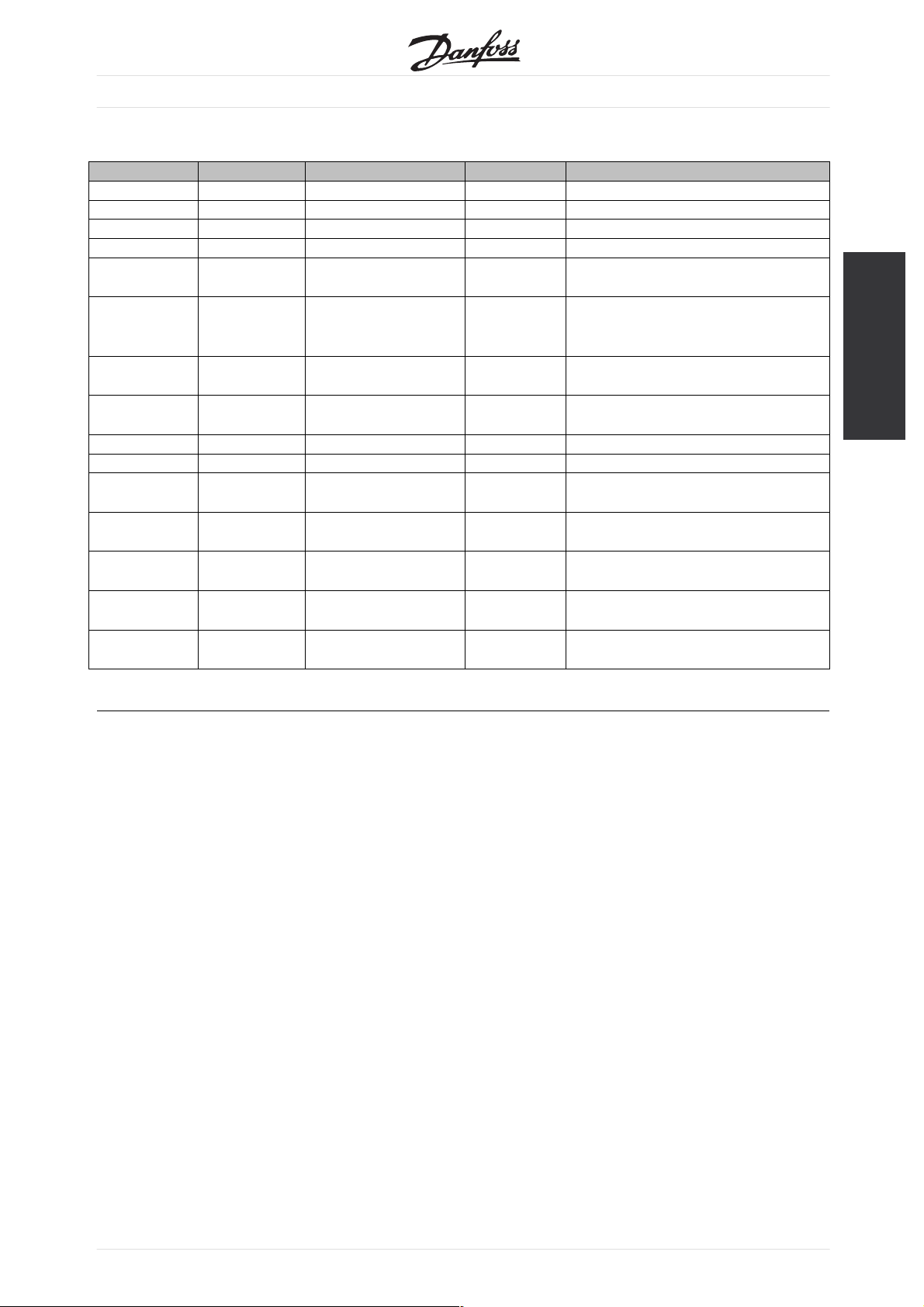
VLT Response Time
■
The update time via the DeviceNet connection
can be d
1. The communication time, which is the time it
2. The internal update time, which is the time it
ivided into two parts:
takes to transmit data from the master to the
slave (VLT with DeviceNet option).
takes to transmit data between the VLT frequency
converter control card and the DeviceNet interface.
VLT®2800 / FCD 300 DeviceNet
Communication time (t
mission speed (baudrate) and the type of master
trans
in use. More slaves or lower transmission speed
will increase the communication time.
) depends on the actual
com
Data Update
time, t
int
Control word via I/O instances 14 msec
Main actual value via I/O instances 44 msec
Status word via I/O instances 14 msec
Reference via I/O instances 44 msec
Control via Class Code 0x29 14 msec
ReferenceviaClassCode0x2A 44msec
Change of parameter via Explicit
94 msec
message and Danfoss Object
Read of parameter via Explicit message
14 msec
and Danfoss Object
8
MG.90.B2.02-VLTisaregisteredDanfosstrademark

Electrical Installation
■
VLT®2800 / FCD 300 DeviceNet
VLT 2800 Connection of the Cable Screen
■
Danfoss recommends that the screen of the DeviceNet
cable be connected to ground at both ends of
the cable at every DeviceNet station (see Danfoss
recommendation for further details).
It is very important to have a low impedance ground
connection of the screen, also at high frequencies.
This can be obtained by connecting the surface
of the screen to ground, for example by means of
a cable clamp or a conductive cable gland. VLT
frequency converter Series are provided with different
clamps and brackets to enable a proper ground
connection of the DeviceNet cable screen. The
screen connection is shown in the drawing.
For fulfilling the CE and EMC compliance.
VLT 2800 ODVA recommendation
Screen must be connected to ground at only
one point on the network.
NB!:
Please note, that this recommendation conflicts
with the EMC correct installation.
Electrical Installation
MG.90.B2.02 - VLT is a registered Danfoss trade mark
9

VLT 2800 Earth Connection
■
portant that all stations connected to the
It is im
DeviceNet network are connected to the same earth
potential. The earth connection must have a low HF
requency) impedance. This can be achieved
(high f
by connecting a large surface area of the cabinet to
ground, for example by mounting the VLT frequency
rter on a conductive rear plate. Especially
conve
when having long distances between the stations
in a DeviceNet network it can be necessary to use
ional potential equalizing cables, connecting the
addit
individual stations to the same earth potential.
VLT 2800 DeviceNet Connection
■
It is essential that the bus line be terminated properly.
match of impedance may result in reflections
Amis
on the line that will corrupt data transmission.
VLT®2800 / FCD 300 DeviceNet
The DeviceNet control card is provided with
a pluggable connector.
By using a pluggable connector as a splice between
trunk lines, removal of devices will not sever the
two
network. Strain relief, if required, must be provided by
the developer. In current installations of this type of
nector, the strain relief is attached to the product.
con
NB!:
Wires should not be installed while the
network is active. This will prevent problems
such as shorting the network supply or
disrupting communications.
VLT 2800 Drop cable
An alternative to splicing two trunk lines in the
nnector on the control card, is using a DeviceNet
co
connection box or a T-connector. For this kind of
installation a drop cable is available as an option.
Drop cable ordering number: 195N3113
NB!:
Please note, that terminal 46 has been removed
from the DeviceNet card, meaning that
parameter 341-342 are not having any function.
10
MG.90.B2.02-VLTisaregisteredDanfosstrademark

FCD 300 Electrical connection
■
The DeviceNet bus connection can be performed
h a plug, that is to be mounted in the
throug
FCD 300 housing (M16 gland hole) and wired
to the inside terminal strip.
Wiring list
VLT®2800 / FCD 300 DeviceNet
M12 Circular connector
Terminal strip Colour Function
4 68 White Can high
5 69 Blue Can low
2 67 Red +24V
3 70 Black GND
1 D Green Drain
DeviceNet plug 175N2279
Electrical Installation
MG.90.B2.02 - VLT is a registered Danfoss trade mark
11

User Interface
■
The DeviceNet control card contains two
or (green/red) LED’s for each connector
bi-col
hookup port, to indicate the state of the device
and network, respectively.
Module LED:
VLT®2800 / FCD 300 DeviceNet
LD1 on VLT 2800 Dual colour
(Green/Red)
Yellow FCD 300 STATUS LED
when selected as DeviceNet in
VLT status
parameter 26
OFF OFF Device is OFF
GREEN YELLOW Device is operational
Flashing GREEN Flashing YELLOW Device is in standby
Flashing RED OFF Device detects a recoverable fault
RED OFF Device detects an unrecoverable
fault
Flashing GREEN/RED Flashing YELLOW Device is self testing
WORK LED:
NET
VLT status LD2 on VLT 2800 Dual
lour (Green/Red)
co
Network is non-
OFF OFF Network is non-
powered/not on-line
twork is on-line but
Ne
ashing GREEN
Fl
not connected
Network is on-line and
nnected
co
Network has a
GREEN GREEN Network is on-line and
Flashing RED OFF Network has a
connection timeout
etwork has a critical
N
ED
R
link failure
Green BUS LED on
D 300
FC
ashing GREEN
Fl
FF
O
VLT status
powered/not on-line
twork is on-line but
Ne
not connected
nnected
co
connection timeout
etwork has a critical
N
link failure
12
MG.90.B2.02-VLTisaregisteredDanfosstrademark

Quick Setup
■
Parameter 800 = "Fieldbus selection".
Parameter 833 = "Fieldbus enable".
Parameter 918 = "Select Bus address".
Parameter 801 = "Select Baudrate".
Parameter 904 = "Choose I/O instances".
Parameter 502 = "Coasting select".
VLT®2800 / FCD 300 DeviceNet
Electrical Installation
MG.90.B2.02 - VLT is a registered Danfoss trade mark
13

Master-Slave configuration
■
System configuration
■
The system configuration of a DeviceNet master and a
VLT 2800/FCD 300 can be split up into two parts.
The first part is the setting of DeviceNet communication
related parameters. These are the baud rate and
station address/MAC ID.
By VLT 2800/FCD 300 these parameters can
be set by the LCP or access via a DeviceNet
configuration tool. None of these parameters
can be set by mechanical switches.
After the baud rate and station address/MAC ID
are set a connection to a DeviceNet DeviceNet
configuration tool can be established.
The second and larger area of a system configuration
is the setting of application related parameters.
EDS files are easy to create and it is strongly
recommended to generate an EDS for each VLT
2800/FCD 300. This can be done by uploading the
EDS file from each drive by a DeviceNet configuration
tool. In the VLT 2800/FCD 300 EDS file it is possible to
configured the drive and read or write to parameters.
The language of the EDS file is depending of the
actual setting of parameter 001 Language.
In parameter 838 EDS Data type it is possible to
choose between two dataformat for uploading EDS
files. Before uploading the EDS file please check if
the master support Errata 1 or Errata 2.
For Off-line configuration Danfoss can provide
you with english EDS files, see section EDS
files for the EDS file name. Contact your local
Danfoss supplier for the EDS files.
VLT®2800 / FCD 300 DeviceNet
Another important configuration parameter is the
selection of communication mechanisms that enable
an efficient and responsive I/O system. By VLT
2800/FCD 300 it is possible to choose between the
following communication mechanisms:
•
Poll I/O
•
Bit Strobe I/O
•
Change-of-state (COS) / Cyclic I/O
•
Explicit Messaging
See DeviceNet Operation Mode in this manual
for further information.
The last configuration parameter is the choice of
Instance type in parameter 904 PPO selection. Here is
it possible to select beween a Danfoss Specific profile
(Instance 100/150 or 101/151) or a ODVA Specific
AC Drive profile (Instance 20/70 or 21/71).
14
MG.90.B2.02-VLTisaregisteredDanfosstrademark

Drive Profile
■
I/O Assembly Instances
■
The I/O Assembly Instance definitions in this section
define the format of the "data" attribute (attribute 3)
for I/O Assembly Instances. I/O Assemblies support
a hierarchy of motor control devices. The device
hierarchy includes motor starters, soft starters, AC
and DC drives, and servo drives. Assembly Instances
are numbered within the hierarchy so that each
device type is assigned a range of Assembly Instance
numbers, with higher functionality devices supporting
VLT®2800 / FCD 300 DeviceNet
higher instance numbers. Devices in the hierarchy
can choose to support instance numbers that are
lower than theirs in the hierarchy. For example an AC
drive may choose to support some I/O Assemblies
in the starter profile to make it easier to interchange
starters and drives within the system.
MG.90.B2.02 - VLT is a registered Danfoss trade mark
Drive Profile
15

Control Word and Status Word under
■
Instance 20/70
Set par
Instance 20/70 [12].
The control word in Instance 20 is defined as
follow
ameter 904 PPO type to select
ing:
Bit Bit = 0 Bit =1
00 Stop Run Fwd.
01 Reserved for future
use
Reserved for future
use
02 No function Fault reset
03 -15Reserved for future
use
Bit 0, Run Fwd:
Bit 0 = "0" means that the VLT frequency
converter has a stop command.
Bit 0 = "1" leads to a start command and the VLT
frequency converter will start to run the motor.
it 2, Fault Reset
B
Bit 0 = "0" means that there is no reset of a trip.
Bit 0 = "1" means that a trip is reset.
Reserved for future
use
VLT®2800 / FCD 300 DeviceNet
and 21/71.
ThestatuswordinInstance70isdefinedasfollowing:
Bit Bit = 0 Bit =1
00 No fault Trip
01 Reserved for future
use
02 Not running Running
03 -15Reserved for future
use
Bit 0,Fault:
Bit 0 = "0" means that there is no fault on
the VLT frequency converter.
Bit 0 = "1" means that there is a fault on the
VLT frequency converter.
B
it 2, Running
Bit 0 = "0" means that there is no active start command.
Bit 0 = "1" means that there is an active start command.
Regarding the Actual output speed, see section
Actual output speed, under Instance 20/70 and 21/71.
Reserved for future
use
Reserved for future
use
Regarding the Speed reference, see section Bus
speed reference value, under Instance 20/70
16
MG.90.B2.02-VLTisaregisteredDanfosstrademark

Control Word and Status Word
■
under Instance 21/71
Set par
Instance 21/71 [13].
The control word in Instance 21 is defined as
followi
ameter 904 PPO type 1 to select
ng:
Bit Bit = 0 Bit =1
00 Stop Run Fwd
01 Stop Run Rev
02 No function Fault reset
03
04
05 Net Ctrl
06 Net Ref
07 15
Bit 0, Run Fwd:
Bit 0 = "0" means that the VLT frequency
converter has a stop command.
Bit 0 = "1" leads to a start command and
the VLT frequency converter will start to run
the motor clockwise.
it 1, Run Rev:
B
Bit 0 = "0" leads to a stop of the motor.
Bit 0 = "1" leads to a start of the motor.
it 2, Fault Reset:
B
Bit 0 = "0" means that there is no reset of a trip.
Bit 0 = "1" means that a trip is reset.
it 5, Net Ref:
B
NB!:
Please note, that a change will have an
effect on parameter 502 - 506.
it 6, Net Crtl:
B
VLT®2800 / FCD 300 DeviceNet
ThestatuswordinInstance71isdefinedasfollowing:
Bit Bit = 0 Bit =1
00 Trip
01 Warning
02 Running 1 Fwd
03 Running 2 Rev.
04 Ready
05 Crtl from Net
06 Ref from Net
07 At reference
08 -15State Attribute
Bit 0,Fault:
Bit 0 = "0" means that there is no fault on
the VLT frequency converter.
Bit 0 = "1" means that there is a fault on the
VLT frequency converter.
B
it 1, Warning:
Bit 0 = "0" means that there is no unusual situation.
Bit 0 = "1" means that an abnormal condition
has arisen .
B
it 2, Running 1:
Bit2="0"meansthatthedriveisnotinoneof
these states or that Run 1 is not set.
Bit 2 = "1" means that the drive state attribute is
enabled or stopping , or that Fault-Stop and bit 0
(Run 1) of the CTW is set at the same time.
B
it 3, Running 2:
Bit 3 = "0" means means, that the drive is not in
one of these states or that Run 2 is not set.
Bit 3 = "1" means that the drive state attribute is
enabled or stopping , or that fault-stop and bit 0
(Run 2) of the CTW is set at the same time.
NB!:
Please note, that a change will have an effect
on parameter 214, 305, 307, 308 and 314.
Regarding the Speed reference, see section Bus
speed reference value, under Instance 20/70
and 21/71.
MG.90.B2.02 - VLT is a registered Danfoss trade mark
it 4, Ready:
B
Bit 4 = "0" means that the state attribute
is in another state.
Bit 4 = "1" means that the state attribute is
ready or enabled or stopping.
Drive Profile
17

Bit 5, Control from net:
Bit5="0"meansthatthedriveiscontrolled
from th
Bit 5 = "1" means that Devicenet has the control
(start, stop, reverse) of the drive.
B
Bit 6 = "0" means that the reference comes
from the drive’s inputs.
Bit 6 = "1" means that the reference is
coming from Devicenet.
B
Bit 7 = "0" means that the motor is running, but
that the present speed is different from the preset
speed
ramped up/down during start/stop.
Bit 7 = "1" means that the drive’s speed
equal
B
Represents the state attribute of the drive, as
indicated in the following table:
e standard inputs.
it 6, Ref from Net:
At reference:
it 7,
reference, i.e. while the speed is being
s the reference.
it 8 - 15, State attribute:
VLT®2800 / FCD 300 DeviceNet
Number Meaning
0 (Vendor specific)
1 Startup
2 Not ready
3 Ready
4 Enabled
5 Stopping
6 Fault stop
7 Faulted
Regarding the Actual output speed, see section Actual
output speed, under Instance 20/70 and 21/71
18
MG.90.B2.02-VLTisaregisteredDanfosstrademark

Bus speed reference value, under Instance
■
20/70 and 21/71
The speed reference value is transmitted to the VLT
frequency converter in the form of a 16-bit word. The
value is transmitted as a whole number. (Negative
figures are formatted by means of 2’s complement.)
us speed reference has the following format:
The b
Parameter 203 = "0" ["ref
00 Hex) [RPM] ⇒ + 32767 (7FFF Hex) [RPM]
0(00
Parameter 203 = "1" [- ref
67 (8000 Hex ) ⇒ +32767 [RPM] (7FFF Hex)
-327
MIN
MAX
⇒ ref
⇒ +ref
MAX
"]
MAX
]
VLT®2800 / FCD 300 DeviceNet
Actual output speed, under Instance 20/70
■
and 21/71
The value of the actual speed of the motor, is
transmitted in the form of a 16-bit word.
The value is transmitted as a whole number. (Negative
figures are formed by means of 2’s complement.)
The actual speed value has the following format:
-32767 (8000 Hex) [RPM] ⇒ +32767 [RPM]
(7FFF Hex) [RPM]
The actual reference [Ref. %] in the VLT depends
on the settings, in the following parameters:
104 Motor frequency
106 Motor Nom. speed
Max. Reference
205
Note that, If the bus speed reference is negative,
and the control word contains a run reverse
signal, the drive runs clockwise.
MG.90.B2.02 - VLT is a registered Danfoss trade mark
Drive Profile
19

Control Word and Status Word under Instance
■
100/150 and 101/151
Set par
Instance 100/150.
The control word in Instance 100/101 is defined as
follow
ameter 904 PPO type 1 [10] to select
ing:
Bit Bit = 0 Bit =1
00 Preset ref. lsb
01 Preset ref. msb
02 DC braking
03 Coasting stop
04 Quick stop
05 Freeze outp. freq.
06 Ramp stop Start
07 Reset
08 Jog
09 Ramp 1 Ramp 2
10 Data not valid Data valid
11 No function
12 No function
13 Select Setup, lsb
14 Select Setup, msb
15 Reversing
Bit 00/01:
Bit 00/01 is used to select between the two
pre-programmed references (parameters 215-218
Preset reference)accordingtothefollowingtable:
Preset ref. Parameter Bit 01 Bit 00
121500
221601
321710
421811
NB!:
In parameter 508 Selection of preset
reference a selection is made to define how
Bit 00/01 gates with the corresponding
function on the digital inputs.
VLT®2800 / FCD 300 DeviceNet
B
it 02, DC brake:
Bit 02 =
voltage and duration are preset in parameters 132
DC brake voltage and parameter 126 DC braking
time.N
is made to define how Bit 02 gates with the
corresponding function on a digital input.
it 03, Coasting stop:
B
Bit 03 =’0’causes the frequency converter to
immediately "let go" of the motor (the output transistors
are "shut off"), so that it coasts to a standstill.
Bit 03 =’1’causes the frequency converter to be able
start the motor if the other starting conditions have
been fulfilled. Note: In parameter 502 Coasting stop
a selection is made to define how Bit 03 gates with
the corresponding function on a digital input.
B
it 04, Quick stop:
Bit 04 =’0’causes a stop, in which the motor’s
disrampeddowntostopviaparameter
spee
212 Quick stop ramp-down time.
B
it 05, Freeze output frequency:
Bit 05 =’0’causes the present output frequency
(in Hz) to freeze. The frozen output frequency can
now only be changed by means of the digital inputs
programmed to Speed up and Speed down.
n only be stopped by the following:
ca
•
Bit03Coastingstop
•
Bit 02 DC braking
•
Dig
stop or Reset and coasting stop.
B
it 06, Ramp stop/start:
Bit 06 =’0’causes a stop, in which the motor’s
speed is ramped down to stop via the selected
ramp down parameter.
Bit 06 =’1’causes the frequency converter to be able
to start the motor, if the other starting conditions have
been fulfilled. Note: In parameter 505 Start a selection
is made to define how Bit 06 Ramp stop/start gates
with the corresponding function on a digital input.
causes DC braking and stop. Brake
’0’
ote: In parameter 504 DC brake a selection
NB!:
reeze output is active, the frequency
If F
converter cannot be stopped via Bit 06 Start
or via a digital input. The frequency converter
ital input programmed to DC braking, Coasting
20
t 07, Reset:
B
i
Bit 07 =’0’does not cause a reset.
Bit 07 =’1’causes the reset of a trip. Reset is
tivated on the signal’s leading edge, i.e. when
ac
changing from logic’0’to logic’1’.
MG.90.B2.02-VLTisaregisteredDanfosstrademark
VLT®2800 / FCD 300 DeviceNet
Bit 08, Jog:
Bit 08 =’1’causes the output frequency to be
determined by parameter 213 Jog frequency.
it 09, Selection of ramp 1/2:
B
Bit 09 = "0" means that ramp 1 is active (parameters
207/208). Bit 09 = "1" means that ramp 2
(parameters 209/210) is active.
B
it 10, Data not valid/Data valid:
Is used to tell the frequency converter whether the
controlwordistobeusedorignored. Bit10=
causes the control word to be ignored, Bit 10
’0’
=’1’causes the control word to be used. This
function is relevant, because the control word is
always contained in the telegram, regardless of which
type of telegram is used, i.e. it is possible to turn
off the control word if you do not wish to use it in
connection with updating or reading parameters.
B
it 11, No function:
Bit 11 has no function.
it 12, No function:
B
Bit 12 has no function.
it 13/14, Selection of Setup:
B
Bits 13 and 14 are used to choose from the four
menu Setups according to the following table:
The Status Word in Instance 150/151 is
defined as following:
Bit Bit = 0 Bit =1
00 Control ready
01 Drive ready
02 Coasting stop
03 No trip Trip
04 Not used
05 Not used
06 Not used
07 No warning Warning
08 Speed ≠ ref. Speed = ref.
09 Local control Ser. communi.
10 Outside
frequency range
Frequency limit
OK
11 Motor running
12
13 Voltage warn.
14 Current limit
15 Thermal warn.
Setup Bit 14 Bit 13
100
201
310
411
ThefunctionisonlypossiblewhenMulti-Setups is
selected in parameter 004 Active Setup.
Note: I parameter 507 Selection of Setup a selection
is made to define how Bit 13/14 gates with the
corresponding function on the digital inputs.
it 15 Reversing:
B
Bit 15 =’0’causes no reversing.
Bit 15 =’1’causes reversing.
Note: In the factory setting reversing is set to
digital in parameter 506 Reversing. Bit 15 only
causes reversing when either Ser. communication,
Logic or or Logic and is selected.
Bit 00, Control ready:
Bit 00 =’1’. The frequency converter is
ready for operation.
Bit 00 =’0’. The frequency converter is
not ready for operation.
it 01, Drive ready:
B
Bit 01 =’1’. The frequency converter is ready for
operation, but there is an active coasting command
via the digital inputs or via serial communication.
B
it 02, Coasting stop:
Bit 02 =’0’. The frequency converter has
released the motor.
Bit 02 =’1’. The frequency converter can start the
motor when a start command is given.
B
it 03, No trip/trip:
Bit 03 =’0’means that the frequency converter
is not in fault mode.
Bit 03 =’1’means that the frequency converter
is tripped, and that it needs a reset signal for
operation to be reestablished.
Drive Profile
MG.90.B2.02 - VLT is a registered Danfoss trade mark
B
it 04, Not used:
Bit04isnotusedinthestatusword.
21

VLT®2800 / FCD 300 DeviceNet
Bit 05, Not used:
Bit 05 is not used in the status word.
B
it 06, Not used:
Bit 06 is not used in the status word.
it 07, No warning/warning:
B
Bit 07 =’0’means that there are no warnings.
Bit 07 =’1’means that a warning has occurred.
B
it 08, Speed≠ ref/speed = ref.:
Bit 08 =’0’means that the motor is running, but that
the present speed is different from the preset speed
reference. It might, for example, be the case while the
speed is being ramped up/down during start/stop.
Bit 08 =’1’means that the motor’s present speed
is the same as the preset speed reference.
B
it 09, Local operation/serial communication control:
Bit 09 =’0’means that [STOP/RESET] is activated
on the control unit, or that Local control in parameter
002 Local/remote operation is selected. It is
not possible to control the frequency converter
via serial communication.
Bit 09 =’1’means that it is possible to control the
frequency converter via serial communication.
Bit 15 =’1’means that the temperature limit has been
exceeded in either the motor, frequency converter or
from a t
hermistor that is connected to a digital input.
B
it 10, Outside frequency range:
Bit 10 =’0’, if the output frequency has reached
the value in parameter 201 Output frequency
low limit or parameter 202 Output frequency
high limit. Bit 10 = "1" means that the output
frequency is within the defined limits.
B
it 11, Running/not running:
Bit 11 =’0’meansthatthemotorisnotrunning.
Bit 11 =’1’means that the frequency converter
has a start signal or that the output frequency
is greater than 0 Hz.
B
it 13, Voltage warning high/low:
Bit 13 =’0’means that there are no voltage warnings.
Bit 13 =’1’means that the DC voltage in the frequency
converter’s intermediate circuit is too low or too high.
it 14, Current limit:
B
Bit 14 =’0’means that the output current is less than
the value in parameter 221 Current Limit I
LIM
.
Bit 14 =’1’means that the output current is
greater than the value in parameter 221 Current
LimitI
and that the frequency converter will
LIM
trip after a set period of time.
B
it 15, Thermal warning:
Bit 15 =’0’means that there is no thermal warning.
22
MG.90.B2.02-VLTisaregisteredDanfosstrademark

Bus reference value
■
The frequency reference value is transmitted to
the VLT frequency converter in the form of a
16-bit word. The value is transmitted as a whole
number (-32767 ⇒ 32767). (Negative figures are
formatted by means of 2’s complement.)
The bus reference has the following format:
Parameter 203 = "0" ["ref
MIN
⇒ ref
MAX
"]
0 ⇒ 16384 (4000 Hex) ~ 0 ⇒ 100% ~ "ref
Parameter 203 = "1" [- ref
MAX
⇒ +ref
MAX
- 16384 (C000 Hex) ⇒ + 16384 (4000 Hex) ~
-100%⇒ + 100% ~ - ref
MAX
⇒ +ref
MAX
MIN
]
⇒ ref
MAX
VLT®2800 / FCD 300 DeviceNet
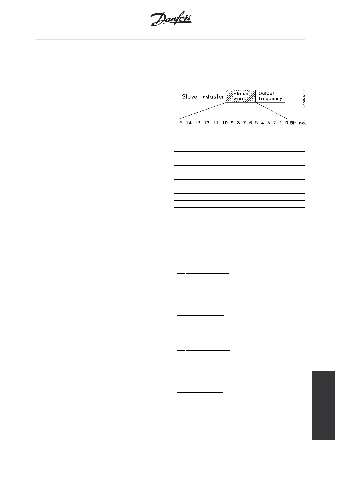
Actual output frequency
■
The value of the actual output frequency of the VLT
frequency converter, is transmitted in the form of a
16-bit word. The value is transmitted as a whole
number (-32767 ⇒ 32767) (Negative figures are
formed by means of 2’s complement).
The actual output frequency has the following format:
-32767 ⇒ +32767.
-16384 (C000 Hex) corresponds to -100%, and
16384 (4000 Hex) corresponds to 100%.
MG.90.B2.02 - VLT is a registered Danfoss trade mark
Drive Profile
23
VLT®2800 / FCD 300 DeviceNet
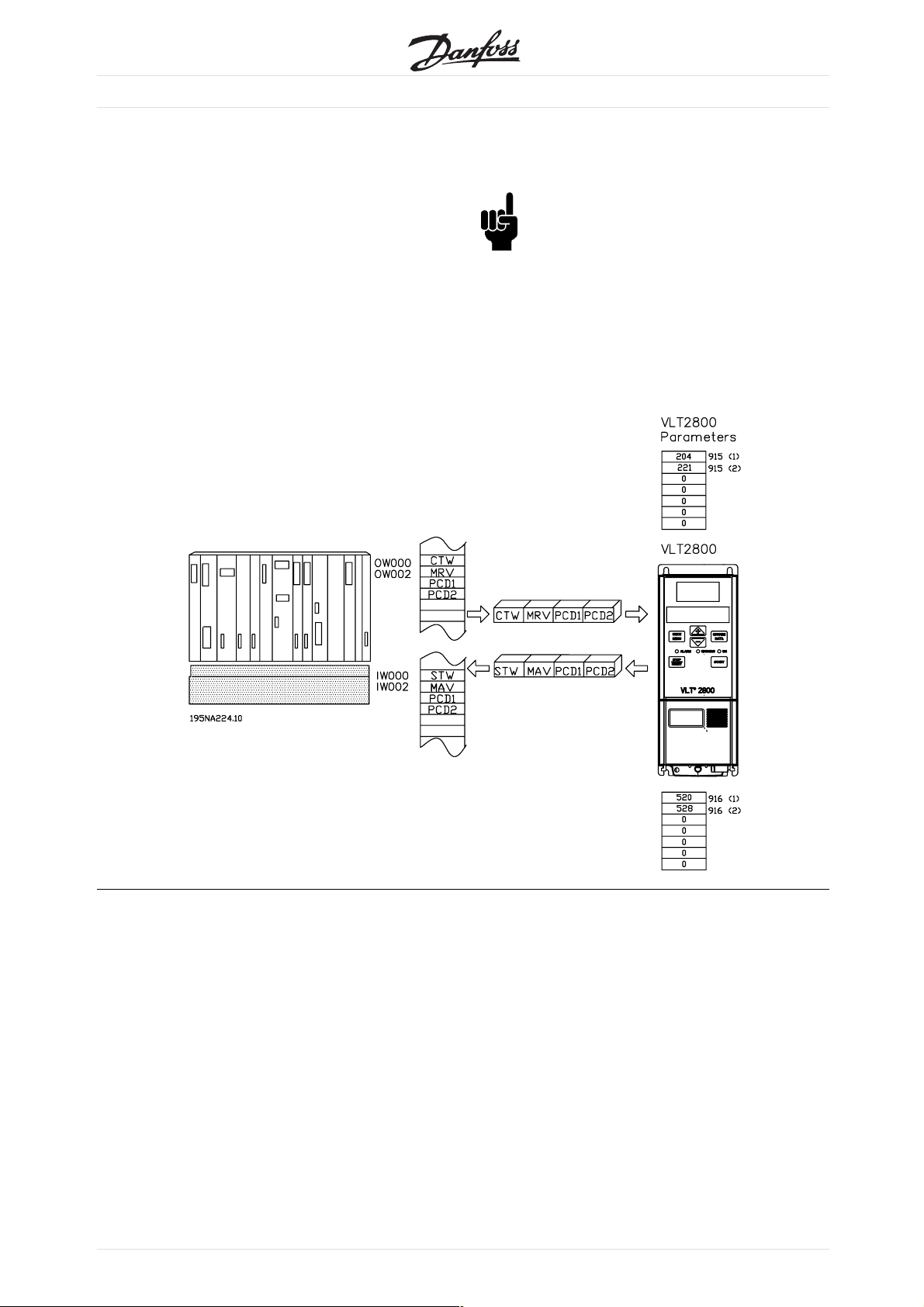
Process Data, PCD
■
The VLT 2800/FCD 300 DeviceNet offers a flexible
way for
Data (I/O words) and the functionality of each word.
To activate the user definable Process data the
user h
parameter 904 PPO selection. This will change
the I/O size to four words in the input and output
area.
profile for the Control-/Status word as well for the
Main Reference Value/Main Actual Value.
The first two words are fixed on the VLT 2800/FCD
300 DeviceNet, whereas the input and output PCD1
the user to customize the number of Process
as to select the I/O Instance 101/151 in
This selection uses the Danfoss specific
and PCD2 can be selected by the user. The number
of PCDs active in a system is fixed to 2 words.
NB!:
The changing of Parameter 904 PPO selection
is first active at the next powerup, and it may
change the mapping of the Masters (PC/PLC).
To enable the use of PCD data of the VLT
FCD 300 DeviceNet the contents of each
2800/
single PCD word has to be configured in Parameter
915 PCD write configuration and 916 PCD read
iguration. Changing Parameter 915/916 has
conf
immediately effect on the PCD data.
24
MG.90.B2.02-VLTisaregisteredDanfosstrademark

VLT®2800 / FCD 300 DeviceNet
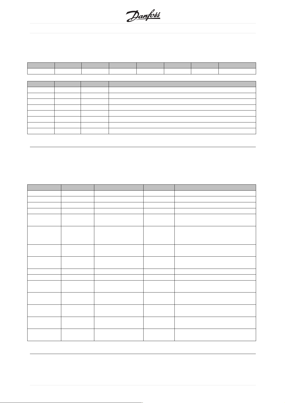
DeviceNet object classes
■
Class Code 0x01
■
For Class Code 0x01, the following Identity Instance
Attributes have been implemented:
Attribute Access Name Datatype Min/Max Units Default Description
1 Get Vendor USINT 97 Danfoss Drives
Vendor Code
2 Get Device Type UINT 2 AC/DC Motor
3 Get Product Code UINT 200 - 399 VLT 2800
400 - 499 FCD 300
4 Get Revision UINT Software version on
5 Get Status UINT
6 Get Serial number UDINT From VLT 2800/FCD
7 Get Product Name String VLT 2800/FCD 300
10 Get/Set Heartbeat
Interval
USINT
See EDS File section
VLT 2800/FCD 300
300
classes
DeviceNet object
Class Code 0x02
■
For Class Code 0x02, the following Message Router
Instance Attributes have been implemented:
Attribute Access Name Datatype Min/Max Units Default Description
1 Get Number of
Class Code 0x03
■
classes
USINT
For Class Code 0x03, the following DeviceNet
Objects have been implemented:
Attribute Access Name Datatype Min/Max Units Default Description
1 Get/Set MAC ID USINT 0-63 63 Node adress
2 Get/Set Baud Rate USINT 0-2 0 0=125
1=250
2=500
3 Get/Set BOI BOOL Bus-Off Interrupt
5 Get Allocate
Information
6 Get MAC ID Switch
changed
7 Get Baud Rate
switched from
last power up
BOOL 0-1 0 The Node adress
BOOL 0-1 0 Tha Baud Rate Switch
Only required
if predefined
Master/Slave is
implemented
Switch has changed
since the last
power-up/reset
has changed since the
last power-up/reset
MG.90.B2.02 - VLT is a registered Danfoss trade mark
25
VLT®2800 / FCD 300 DeviceNet
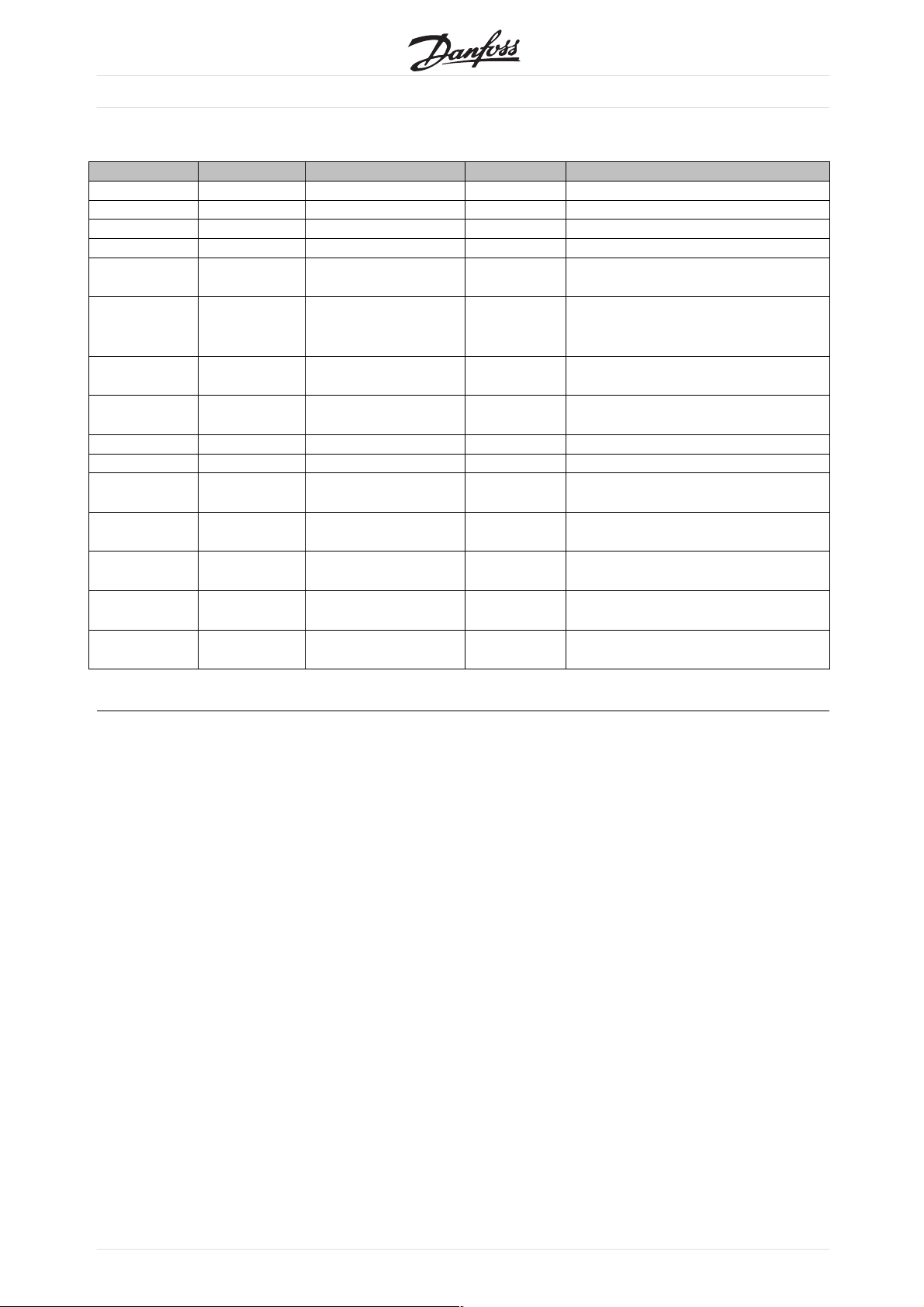
Class Code 0x04
■
For Class Code 0x04, the following Assembly Object
ces have been implemented:
Instan
Attribute Access Name Datatype Min/Max Units Default Description
3 Set Data ARRA
Attribute Access Datasize Description
20 Set 2Words DeviceNet AC/DC Profile
21 Set 2Words DeviceNet AC/DC Profile
70 Get 2Words DeviceNet AC/DC Profile
71 Get 2Words DeviceNet AC/DC Profile
100 Set 2Words Danfoss specific, no PCD Words
101 Set 4Words Danfoss specific, 2 PCD Words
150 Get 2Words Danfoss specific, no PCD Words
151 Get 4Words Danfoss specific, 2 PCD Words
Class Code 0x05
■
For Class Code 0x05, the following Connection
Object Attributes have been implemented:
Y
Instance 1 Attributes: Explicit Message Instance
Attribute Access Name Datatype Description
1 Get State USINT State of the object
2 Get Instance Type USINT Indicates either I/O or Messages Connection
3 Get Transport Class Trigger USINT Defines behaviour of the Connection
4 Get Produced Connection ID UINT CAN Identifier Field when the Connection transmits
5 Get Consumed Connection ID UINT AN Identifier Field value that denotes message to
be received
6 Get Initial Communication
Characteristics
7 Get Produced Connection size UINT Maximum number of bytes transmitted across this
8 Get Consumed Connection size UINT Maximum number of bytes received across this
9 Get/Set Expected Package UINT Defines timming associated w ith this Connection
12 Get Watchdog timeout action USINT Defines how to handle Inactivity/Watchdog timeout
13 Get Produced Connection Path
Length
14 Get Produced Connection Path Array of USINT Specifies the Application Object(s) whose data is to
15 Get Consumed Connection Path
Length
16 Get Consumed Connection Path Array of USINT Specifies the Application object(s) that are to receive
17 Get Production Inhibit Time UINT Defines minimum time between new data production.
USINT Defines the message group(s) across which
productions and consumptions associated with this
Connection occur
Connection
Connection
UINT Number of Bytes in the produced connection path
attribute
be produced by these Connection Objects
UINT Number of bytes in the consumed connection path
attribute
the data consumed by this Connection object
This attribute is required for I/O Client connection
26
MG.90.B2.02-VLTisaregisteredDanfosstrademark

VLT®2800 / FCD 300 DeviceNet
Instance 2 Attributes: Polled I/O
Attribute Access Name Datatype Description
1 Get State USINT State of the object
2 Get Instance Type USINT Indicates either I/O or Messages Connection
3 Get Transport Class Trigger USINT Defines behaviour of the Connection
4 Get Produced Connection ID UINT CAN Identifier Field when the Connection transmits
5 Get Consumed Connection ID UINT AN Identifier Field value that denotes message to
be received
6 Get Initial
7 Get Produced Connection size UINT Maximum number of bytes transmitted across this
8 Get Consume
9 Get/Set Expected Package UINT Defines timming associated w ith this Connection
12 Get Watchdog timeout action USINT Defines how to handle Inactivity/Watchdog timeout
13 Get Produced Connection Path
14 Get Produced Connection Path Array of USINT Specifies the Application Object(s) whose data is to
15 Get Consumed Connection Path
16 Get Consumed Connection Path Array of USINT Specifies the Application object(s) that are to receive
17 Get Production Inhibit Time UINT Defines minimum time between new data production.
Communication
Characteristics
d Connection size
Length
Length
USINT Defines
UINT Maximum
UINT Number of Bytes in the produced connection path
UINT Number of bytes in the consumed connection path
the message group(s) across which
productions and consumptions associated with this
Connection occur
Connection
number of bytes received across this
Connection
attribute
ced by these Connection Objects
be produ
attribute
the data consumed by this Connection object
This attribute is required for I/O Client connection
classes
DeviceNet object
MG.90.B2.02 - VLT is a registered Danfoss trade mark
27
VLT®2800 / FCD 300 DeviceNet
Instance 3: Bit Strobe
Attribute Access Name Datatype Description
1 Get State USINT State of the object
2 Get Instance Type USINT Indicates either I/O or Messages Connection
3 Get Transport Class Trigger USINT Defines behaviour of the Connection
4 Get Produced Connection ID UINT CAN Identifier Field when the Connection transmits
5 Get Consumed Connection ID UiNT AN Identifier Field value that denotes message to
be received
6 Get Initial
7 Get Produced Connection size UINT Maximum number of bytes transmitted across this
8 Get Consume
9 Get/Set Expected Package UINT Defines timming associated w ith this Connection
12 Get Watchdog timeout action USINT Defines how to handle Inactivity/Watchdog timeout
13 Get Produced Connection Path
14 Get Produced Connection Path Array of USINT Specifies the Application Object(s) whose data is to
15 Get Consumed Connection Path
16 Get Consumed Connection Path Array of USINT Specifies the Application object(s) that are to receive
17 Get Production Inhibit Time UINT Defines minimum time between new data production.
Communication
Characteristics
d Connection size
Length
Length
USINT Defines
UINT Maximum
UINT Number of Bytes in the produced connection path
UINT Number of bytes in the consumed connection path
the message group(s) across which
productions and consumptions associated with this
Connection occur
Connection
number of bytes received across this
Connection
attribute
ced by these Connection Objects
be produ
attribute
the data consumed by this Connection object
This attribute is required for I/O Client connection
28
MG.90.B2.02-VLTisaregisteredDanfosstrademark
VLT®2800 / FCD 300 DeviceNet
Instance 4: Change of State/Cycle
Attribute Access Name Datatype Description
1 Get State USINT State of the object
2 Get Instance Type USINT Indicates either I/O or Messages Connection
3 Get Transport Class Trigger USINT Defines behaviour of the Connection
4 Get Produced Connection ID UINT CAN Identifier Field when the Connection transmits
5 Get Consumed Connection ID UiNT AN Identifier Field value that denotes message to
be received
6 Get Initial
7 Get Produced Connection size UINT Maximum number of bytes transmitted across this
8 Get Consume
9 Get/Set Expected Package UINT Defines timming associated w ith this Connection
12 Get Watchdog timeout action USINT Defines how to handle Inactivity/Watchdog timeout
13 Get Produced Connection Path
14 Get Produced Connection Path Array of USINT Specifies the Application Object(s) whose data is to
15 Get Consumed Connection Path
16 Get Consumed Connection Path Array of USINT Specifies the Application object(s) that are to receive
17 Get Production Inhibit Time UINT Defines minimum time between new data production.
Communication
Characteristics
d Connection size
Length
Length
USINT Defines
UINT Maximum
UINT Number of Bytes in the produced connection path
UINT Number of bytes in the consumed connection path
the message group(s) across which
productions and consumptions associated with this
Connection occur
Connection
number of bytes received across this
Connection
attribute
ced by these Connection Objects
be produ
attribute
the data consumed by this Connection object
This attribute is required for I/O Client connection
classes
DeviceNet object
MG.90.B2.02 - VLT is a registered Danfoss trade mark
29
VLT®2800 / FCD 300 DeviceNet
Class Code 0x28
■
For Class Code 0x28, the following Motor Data
ce Attributes have been implemented:
Instan
Attribute Access Name Datatype Min/Max Units Default Description
3 Get/
6 Get/Set Rated
7 Get/Set Rated
8 Get/Set Rated power UDINT 0-18500 Watt Drive depend Rated Power at Rated Frequency
9 Get/Set Rated
15 Get/Set Base Speed UNIT 100-60000 RPM Drive depend Nominal Motor speed
Set
rType
Moto
Current
e
Voltag
Frequency
T
USIN
UNIT 0-100.00 100 mA Drive depend Rates Stator Current
UNIT 200-500 Volt Drive depend Rated Base Voltage
UNIT 1-1000 Hz Drive de
0-10 7 0=No
pend
nStandardMotor
1=PMDCMotor
2=FCDCMotor
3=PMS
4 = FC Synchronous Motor
5 = Switched Reluctance Motor
6=Wou
7 = Squirrel Cage Induction Motor
8 = Stepper Motor
9=Sinu
10 = Trapezoidal PM BL Motor
(from Motor nameplate)
(from M
Rated El
(from Motor nameplate)
(from Motor nameplate)
ynchronous Motor
nd Rotor Induction Motor
soidal PM BL Motor
otor nameplate)
ec. Frequency
30
MG.90.B2.02-VLTisaregisteredDanfosstrademark

VLT®2800 / FCD 300 DeviceNet
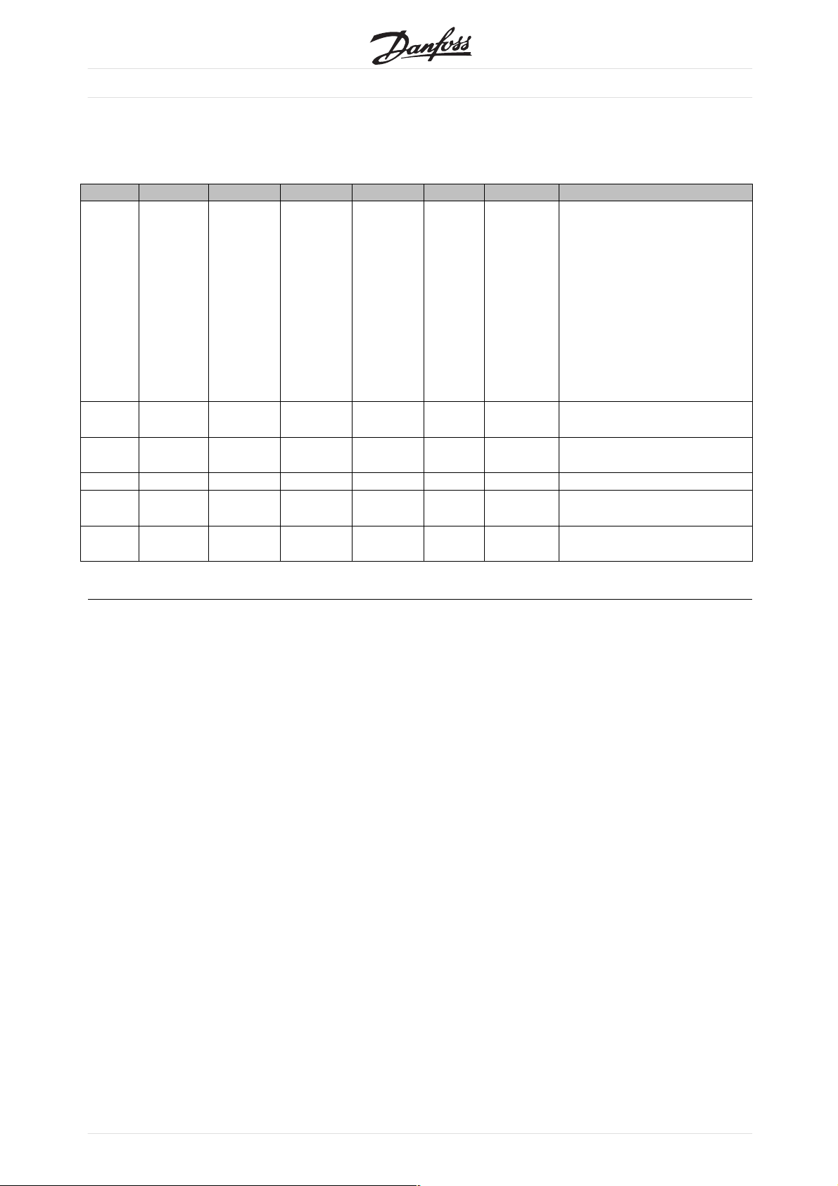
Class Code 0x29
■
For Class Code 0x29, the following Control Supervisory
ce Attributes have been implemented:
Instan
Attribute Access Name Datatype Min/Max Default Description
3 Get/
4 Get/Set Run 2 Bool 0-1 Run rev, see note below
5 Get/S
6 Get State USINT 0-7 0 = Vendor Specific
7 Get Running 1 Bool 0-1 0 0 = Other State
8 Get Running 2 Bool 0-1 0 0 = Other State
Set
Run 1 Bool 0-1 Run F
et
NetCt
rl
Bool 0-1 1 0=Loc
wd, see note below
al Control
1 = Control from Network
1=Startup
2 = Not ready
3 = Ready
4=Enabled
5=Stopping
6=FaultStop
7 = Fault
ble and Run 1) or
1=(Ena
(Stopping and Running 1 ) or
(Fault stop and Running 1)
1=(EnableandRun2)or
(Stopping and Running 2) or
(Fault stop and Running 2)
classes
DeviceNet object
9 Get Ready Bool 0-1 0 = Other State
1 = Ready or Enabled or Stopping
10 Get Fault Bool 0-1 0=NoFaultsPresent
1 = Fault Occured (latched)
12 Get/Set Fault Rst Bool 0-1 0 0=NoAction
0 →1=ResetFault
13 Get Fault Code UINT
15 Get Crt From Net Bool 0-1 1 0 = Control is local
1 = Control is from Network
16 Get/Set DN Fault Mode USINT 0-2 1 Action on loss of DeviceNet
0=Fault+Stop
1 = Ignore (Warning Optional)
2=Danfossspecific
AC drive profile is only available if selecting
Instance 20/70 or 21/71
MG.90.B2.02 - VLT is a registered Danfoss trade mark
31

VLT®2800 / FCD 300 DeviceNet
Class Code 0x2A
■
For Class Code 0x2A, the following AC/DC Drive
ce Attributes have been implemented:
Instan
Attribute Access Name Datatype Min/Max Default Description
3 Get At Re
4 Get/Set Net Ref Bool 0-1 1 0 = Set reference not DN Control
6 Get/Set Drive Mode USINT 0-5 1 0 = Vendor specific mode
7 Get Speed Actual INT RPM / 2
8 Get/Set Speed Ref INT RPM / 2
22 Get/Set Speed Scale SINT -128 - 127 Speed scaling factor
ference
Bool 0-1 0=Dr
Speed Scale
Speed Scale
ive not at reference
1 = Drive actual at reference
1 = Set Reference at DN Control
n loop speed (Frequency)
1=Ope
2 = Closed loop speed control
3 = Torque control
ess control (e.g. PI)
4=Proc
5=Positioncontrol
Actual drive speed (best approximation)
Speed Reference
29 Get Ref from Net Bool 0-1 0 = Local speed reference
1 = DeviceNet speed reference
32
MG.90.B2.02-VLTisaregisteredDanfosstrademark

Danfoss Classes
■
VLT®2800 / FCD 300 DeviceNet
Parameter 001 - 099 Class 100
Parameter 101 - 199 Class 101
Parameter 200 - 299 Class 102
Parameter 300 - 399 Class 103
Parameter 400 - 499 Class 104
Parameter 500 - 599 Class 105
Parameter 600 - 699 Class 106
Parameter 700 - 799 Class 107
Parameter 800 - 899 Class 108
Parameter 900 - 999 Class 109
Index Pointer Class 120
Instance Description:
The Danfoss VLT 2800/FCD 300 DeviceNet only use
Instance 1, so always leave this at the value of 1.
Attribute Description:
The attributes for the VLT 2800/FCD 300 parameter
are the last 2 (two) digits of the parameter + 100.
Example:
The parameter 529 (Analog input, terminal
53) will have the following:
Class 105
Instance 1
Attribute 129
Reading/writing to parameters with index:
Parameters of type indexed (e.g. 915 & 916)
need special handling since DeviceNet does
not support indexed addressing.
The way to handle this in the VLT 2800/FCD 300, is
by using the the Danfoss Class 120. which serves
as an index pointer. The pointer has to be set up
before e
Example:
Write 518 in index 2 in parameter 916 PCD Read:
very read/write of an indexed parameter.
NB!:
If two masters are accessing this feature at
the same ime, wrong data may occur.
classes
DeviceNet object
First setup the index pointer in class 120.
In this example index 2:
Class Instance Attribute Variable
120 Dec 1Dec 100 Dec 2Dec
78 Hex 1Hex 64 Hex 2hex
Next step is to write the data (in this example
518) to parameter 916 PCD Read
Class Instance Attribute Variable
109 Dec 1Dec 116 Dec 518 Dec
6D Hex 1Hex 74 Hex 206 hex
MG.90.B2.02 - VLT is a registered Danfoss trade mark
33

DeviceNet Operation Mode
■
Bit Strobe
■
Bit strobe provides the ability of a slave to react to
a special command of the master in a defined way.
Master sends the Bit strobe command to many
devices at a time, only one bit of the message is
assigned to a single slave at a time, what means, that
only the state "TRUE" or "FALSE" can be transmitted.
This parameter may be used for synchronizing drives.
Executing the Bit-Strobe command with a value of
"1" (TRUE) leads the addressed drive to ignore the
input values of the control word and the reference
transmitted via the Assembly Instances , the Control
Supervisor and the AC/DC Drive Object. If the
Bit-Strobe command is executed with a value of "0"
VLT®2800 / FCD 300 DeviceNet
(FALSE), the drive reacts according to the input values
again. This means, that the value of the Bit-Strobe
command is stored internally and the drive reacts
according the value of the Bit-Strobe command.
The master can transmit the new reference when
the Bit-Strobe value is "1", it must be valid after
the execution of the Bit-Strobe command with the
value "0" [10]. After a Bit-Strobe command has
been executed, the device must answer with the
according I/O telegram and ignore any CTW, MAV
and PCDs transmitted by the master.
34
MG.90.B2.02-VLTisaregisteredDanfosstrademark

Polling
■
This is the standard Devicenet operation mode,
g that data can be acquired by the master via
meanin
polling using the Devicenet or Danfoss objects.
Change of State, COS
■
This operation modus can be used in order to
minimize network traffic. Messages are only sent to
the consumer, if a defined state or value has changed.
In order to signalize, that the connection has not been
crashed or is powered off, a Heartbeat Message is
transmitted within a specified time (Heartbeat Interval).
This time is defined in attribute heartbeat time of the
connection object class code 0x05. To prevent the
device from producing heavy network traffic, if a value
often changes, the Production Inhibit Time (attribute of
connection object) is defined. This parameter defines
the minimum delay between 2 c-o-s messages.
The Attribute Expected Package Rate defines
the maximum time between two Cos messages
even though the value has not changed. Cos
operation modus can only be used on I/O
instances defined in parameter 904.
VLT®2800 / FCD 300 DeviceNet
Mode
DeviceNet Operation
Parameters 834 through 837 can be used for filtering
ut undesired events for Cos. If a filter bit is set
o
to 0, the corresponding I/0 instance bit will not
be able to produce a Cos message.
MG.90.B2.02 - VLT is a registered Danfoss trade mark
35

EDS Files
■
VLT®2800 / FCD 300 DeviceNet
Note that the EDS files can be uploaded from the
VLT frequency converters via RS Networx. Before
uploading the EDS file you must check the version
of RS Networx in Help and About RS Networx. RS
Networx version 3.11.00 supports the format Errata 2
and no changes must be made to the VLT frequency
converter. RS Networx version 3.00.00 supports
Errata 1 and parameter 838 EDS Data type must be
set to Errata 1 and power must be re-cycle.
VLT 2800 US version with DeviceNet
Product Code Drive Model Drive Rating
232 VLT 2803 0.37 (0.50) 200 - 240 V
233 VLT 2805 0.55 (0.75) 200 - 240 V
234 VLT 2807 0.75 (1.00) 200 - 240 V
235 VLT 2811 1.10 (1.50) 200 - 240 V
236 VLT 2815 1.50 (2.00) 200 - 240 V
237 VLT 2822 2.20 (3.00) 200 - 240 V
238 VLT 2830 3.70 (5.00) 200 - 240 V
283 VLT 2805 0.55 (0.75) 380 - 480 V
284 VLT 2807 0.75 (1.00) 380 - 480 V
285 VLT 2811 1.10 (1.50) 380 - 480 V
286 VLT 2815 1.50 (2.00) 380 - 480 V
287 VLT 2822 2.20 (3.00) 380 - 480 V
288 VLT 2830 3.00 (4.00) 380 - 480 V
289 VLT 2840 4.00 (5.00) 380 - 480 V
290 VLT 2855 5.50 (7.50) 380 - 480 V
291 VLT 2875 7.50 (10.00) 380 - 480 V
292 VLT 2880 11.0 (15.00) 380 - 480 V
293 VLT 2881 15.0 (20.00) 380 - 480 V
294 VLT 2882 18.5 (25.00) 380 - 480 V
Start RS Networx and go online and the VLT
2800/FCD 300 will be shown as a grey box as
unregistered device. Click on the VLT 2800/FCD
300 and go to Tools and choose EDS Wizard. Click
on next by the EDS wizard and choose Create an
EDS file. RS Networx will now start to create an
EDS file from the VLT frequency converter.
To upload EDS files please visit www.DanfossDrives.com
Vol tage EDS File Name
kW (HP)
36
MG.90.B2.02-VLTisaregisteredDanfosstrademark
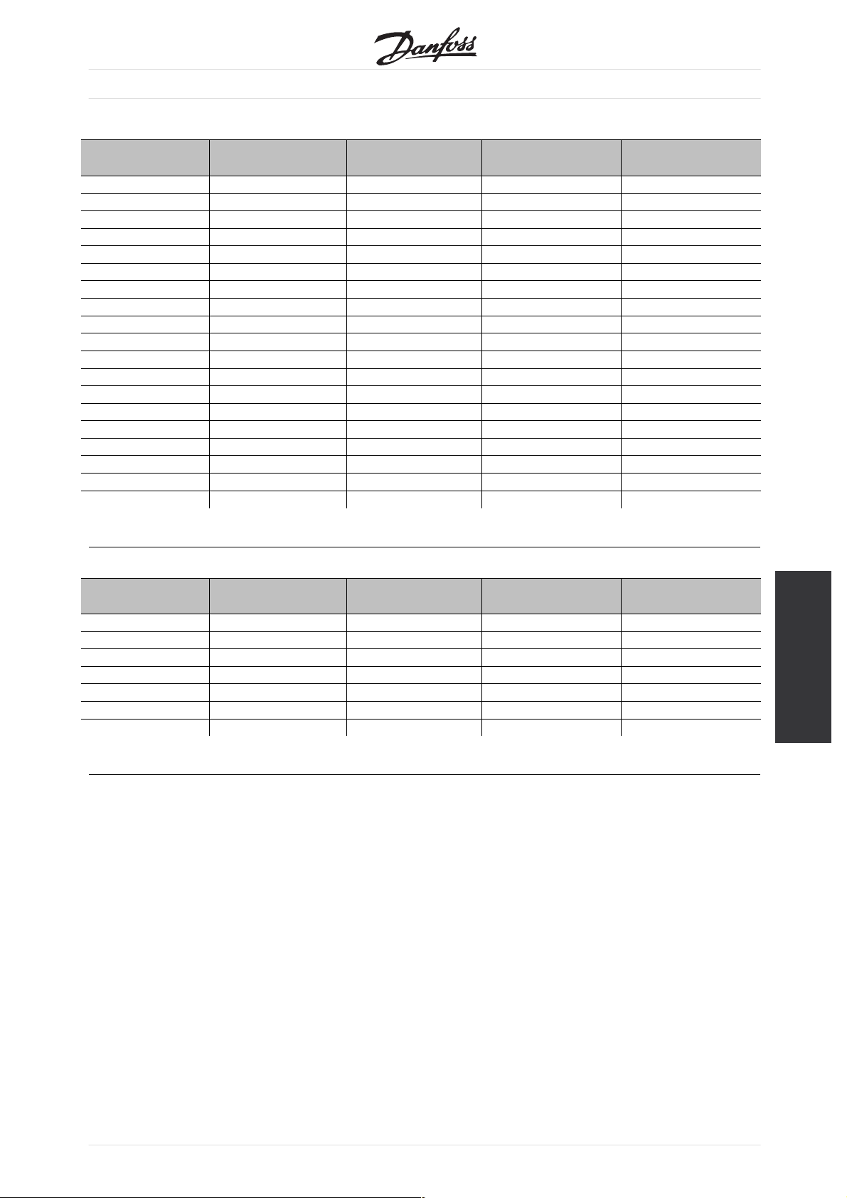
VLT 2800 European version with DeviceNet
Product Code Drive Model Drive Rating
332 VLT 2803 0.37 (0.50) 200 - 240 V
333 VLT 2805 0.55 (0.75) 200 - 240 V
334 VLT 2807 0.75 (1.00) 200 - 240 V
335 VLT 2811 1.10 (1.50) 200 - 240 V
336 VLT 2815 1.50 (2.00) 200 - 240 V
337 VLT 2822 2.20 (3.00) 200 - 240 V
338 VLT 2830 3.70 (5.00) 200 - 240 V
383 VLT 2805 0.55 (0.75) 380 - 480 V
384 VLT 2807 0.75 (1.00) 380 - 480 V
385 VLT 2811 1.10 (1.50) 380 - 480 V
386 VLT 2815 1.50 (2.00) 380 - 480 V
387 VLT 2822 2.20 (3.00) 380 - 480 V
388 VLT 2830 3.00 (4.00) 380 - 480 V
389 VLT 2840 4.00 (5.00) 380 - 480 V
390 VLT 2855 5.50 (7.50) 380 - 480 V
391 VLT 2875 7.50 (10.00) 380 - 480 V
392 VLT 2880 11.0 (15.00) 380 - 480 V
393 VLT 2881 15.0 (20.00) 380 - 480 V
394 VLT 2882 18.5 (25.00) 380 - 480 V
VLT®2800 / FCD 300 DeviceNet
Vol tage EDS File Name
kW (HP
FCD 300 European version with DeviceNet
Product Code Drive Model Drive Rating
480 FCD 303 0.37 (0.50) 380 - 480 V
481 FCD 305 0.55 (0.75) 380 - 480 V
482 FCD 307 0.75 (1.00) 380 - 480 V
483 FCD 311 1.10 (1.50) 380 - 480 V
484 FCD 315 1.50 (2.00) 380 - 480 V
485 FCD 322 2.20 (3.00) 380 - 480 V
486 FCD 330 3.00 (4.00) 380 - 480 V
kW (HP
Vol tage EDS File Name
EDS
Files
MG.90.B2.02 - VLT is a registered Danfoss trade mark
37

VLT®2800 / FCD 300 DeviceNet
Special Attention
■
NB!:
Please note, that terminal 46 has been
removed from the VLT 2800 DeviceNet
card, meaning that parameter 341 - 342
are not having any function.
•
002:
If operation site = Local, then control via
DeviceNet is not possible.
•
502-508:
tion of how to gate DeviceNet control
Selec
commands with control commands on the digital
inputs of the control card.
•
515-538:
Data read out parameters that can be used to read
various actual data from the VLT, as for example
actual status on the analog and digital inputs of the
control card thus using these as inputs to the master.
•
Select DeviceNet in this parameter.
800 P
rotocol Select
Description of choice:
For FCD 300 connections see FCD 300 Design
Guide MG.04.AX.YY par. 620.
Normal function [0] is used for normal
operation of the motor.
Control card test [2] is selected if you wish to check
the control card’s analog/digital input, analog/digital
outputs, relay outputs and 10 V and 24 V voltages.
The test is performed as follows:
18, 27, 33 are connected to relay terminal 03.
19, 29, V+ are connected to relay terminal 02.
50 - 53 are connected.
42 - 60 are connected.
55 - V- are connected.
12 is connected to relay terminal 01.
•
801 Baud rate select
Selection of DeviceNet transmission speed.
•
833 Fieldbus enable
le the DeviceNet communication. The
Enab
default setting is disable.
•
904 PPO selection
Selection of Instance type.
•
918 Station address / MAC ID
he Station address / MAC ID in this parameter.
Set t
620 Operation Mode
(OPERATION MODE)
Val ue:
✭Normal operation (NORMAL OPERATION)
Control card test (CONTROL CARD TEST)
Initialize (INITIALIZE)
Function:
In addition to its normal function, this parameter
can be used to test the control card.
There is also the opportunity to perform an
initialisation at the factory setting for all parameters
in all Setups, with the exception of parameters
500 Address, 501 Baudrate, 600-605 Operating
data and 615-617 Fault log.
✭
= factory setting. () = display text [] = value for use in communication via serial communication port
[0]
[2]
[3]
Use the following procedure for the control card test:
1. Select control card test.
2. Disconnect the mains voltage and wait until the
light in the display has disappeared.
3. Mount according to drawing and description.
4. Connect the mains voltage.
5. The frequency converter automatically undertakes
a test of the control card.
If the frequency converter displays a fault code from
37-45, the control card test has failed. Replace the
control card to start up the frequency converter.
If the frequency converter comes into Display mode,
the test is OK. Remove the test connector and
the frequency converter is ready for operation.
Parameter 620 Operating mode is automatically
set to Normal operation [0].
Initialisation [3] is selected if you wish to use
the unit’s factory setting.
Procedure for initialisation:
1. Select Initialisation [3].
2. Disconnect the mains voltage and wait until the
light in the display has disappeared.
3. Connect the mains voltage.
4. An initialisation is performed in all parameters
in all Setups, with the exception of parameters
38
MG.90.B2.02-VLTisaregisteredDanfosstrademark

VLT®2800 / FCD 300 DeviceNet
500 Address, 501 Baudrate, 600-605 Operating
data, 615-617 Fault log, 833 Fieldbus enable
and 904
800 Pr
Val ue:
✭DeviceNet (DEVICENET)
Function:
This parameter is read only.
801 Baud Rate Select
Val ue:
✭125 kbps (125 KBPS)
250 kbps (250 KBPS)
500 kbps (500 KBPS)
Function:
Selection of the DeviceNet transmission speed. It
must correspond to the transmission speed of the
master and the other DeviceNet nodes.
Description of choice:
Select the baud rate.
PPO selection.
otocol Select
(PROTOCOL SELECT)
(BAUD RATE SELECT)
[2]
[20]
[21]
[22]
804 Bus time out function
(TIME OUT FUNCT.)
Val ue:
✭OFF (OFF)
Freeze output frequency (FREEZE OUTPUT)
Stop with auto restart (STOP)
Output = jog frequency (JOGGING)
Output = max speed (MAX SPEED)
Stop with trip (STOP AND TRIP)
Select Setup 2 (SELECT SETUP 2)
Function:
The timeout counter is activated at the first receipt
of a valid control word, i.e. bit 10 = OK.
Description of choice:
The VLT remains in the timeout status until one
of the following four conditions occurs.
1. A valid con
and control via DeviceNet is resumed with the
current control word. If the timeout function Stop
with trip
or control panel is necessary.
2. Parameter 002 = Local operation => local control
through c
3. Parameter 804 = Off => control via DeviceNet
is resumed, with the control word used
last bein
trol word (bit 10 = OK) is received
is selected a reset via bus, terminals
ontrol panel is active.
g taken.
[0]
[1]
[2]
[3]
[4]
[5]
[8]
NB!:
Note that a change of this parameter is
first executed at next power up.
803 Bus time out
(BUS TIME OUT)
Val ue:
1 - 99 sec
Function:
If the VLT frequency converter doesn’t receive a
control word for a period longer than the time set in
this parameter, the function selected in parameter
804 Response after bus errror will be activated.
Description of choice:
Set the desired time.
Please note, that when the drive is running Cyclic or
COS mode, the Bus time out has to be set higher
than Heartbeat Rate. If not, the VLT will time out.
✭ 1 sec
805 Bit 10 function
(BIT 10 FUNCTION)
Function:
This parameter is read only.
832 Bus Off Interrupt Behavior
(BUS OFF INT. BEH)
Val ue:
✭Hold the device in bus-off state (HOLD CAN)
Reset the device and continue communicating
(RESET CAN)
Function:
This param
behavior if a bus-off interrupt is detected.
Description of choice:
If this parameter is set to Hold the device in bus-off
state [0] and a bus-off event is detected, the VLT
2800/FCD 300 will go into reset/bus-off state.
eter defines the VLT 2800/FCD 300
[0]
[1]
Programming
✭
= factory setting. () = display text [] = value for use in communication via serial communication port
MG.90.B2.02 - VLT is a registered Danfoss trade mark
39

VLT®2800 / FCD 300 DeviceNet
If this parameter is set to Reset the device and continue
communicating [1] and a bus-off event is detected the
VLT 2800/FCD 300 will try to reset and re-initialise
the CAN chip and to continue communication.
833 Fieldbus enable
(FIELDBUS ENABLE)
Val ue:
✭Disabled (DISABLE)
Enabled (ENABLE)
Function:
This parameter allows to disable the
communication interface.
Description of choice:
Select Enable [1] to start the DeviceNet communication.
If Disable [0] is selected no communication warning will
appear, since the communication interface is disabled.
NB!:
Note that a change of this parameter is
first executed at next power up.
834 Filter Mask for status word
(COS FILTER 1)
Val ue:
0000 - FFFF Hex
✭ FFFF Hex
[0]
[1]
Description of choice:
Setup the filter mask for the Main actual value.
836 Filter Mask PCD 1
(COS FILTER 3)
Val ue:
0000 - FFFF Hex
Function:
When operating in COS (Change-Of-State) it is
e to filter out bits in PCD 1 that should
possibl
not be send if they changes.
Description of choice:
Setup the filter mask for PCD 1.
837 Filter Mask PCD 2
(COS FILTER 4)
Val ue:
0000 - FFFF Hex
Function:
When operating in COS (Change-Of-State) it is
possible to filter out bits in PCD 2 that should
not be send if they changes.
Description of choice:
Setup the filter mask for PCD 2.
✭ FFFF Hex
✭ FFFF Hex
Function:
When operating in COS (Change-Of-State) it is
possible to filter out bits in the status word that
should not be send if they changes.
Description of choice:
Setup the filter mask for the status word.
NB!:
For further information, see the section
Change of state, Cos.
835 Filter Mask for main actual value
(COS FILTER 2)
Val ue:
0000 - FFFF Hex
Function:
When operating in COS (Change-Of-State) it is
possible to filter out bits in the Main actual value
that should not be send if they changes.
✭ FFFF Hex
838 EDS Data Types
(EDS DATA TYPES)
Val ue:
Errata 1 (ERRATA 1)
✭Errata 2 (ERRATA 2)
Function:
In this parameter it is possible to select between
two data types when uploading an EDS file from the
VLT frequency converter. The current versions of the
configuration tools like DeviceNet Manager and RS
Networx can only handle data type Errata 1.
Description of choice:
Select Errata 1 if DeviceNet Manager or RS
Networx version 3.00 is used.
Select Errata 2 if DeviceNet Manager or RS Networx
version 3.11 or higher is used.
[0]
[1]
✭ = factory setting. () = display text [] = value for use in communication via serial communication port
40
MG.90.B2.02-VLTisaregisteredDanfosstrademark

VLT®2800 / FCD 300 DeviceNet
850 Readout Transmit Error Counter
(R.OUT.TR.ERR.CO.)
Function:
This parameter is a read out of the Transmit Error
Counter of the CAN controller since the last power up.
851 Readout Receive Error Counter
(R.OUT.RE.ERR.CO.)
Function:
This parameter is a read out of the Receive Error
Counter of the CAN controller since the last power up.
852 Readout Bus Off Counter
(R.OUT.BUS.OFF.CO)
Function:
This parameter is a read out of the how many Bus Off
events there has been since the last power up.
881 Main Actual Value
(MAIN ACTUAL VAL.)
Function:
This parameter is a read out of the VLT frequency
Main Actual Value in the range of 0 - 4000 Hex.
This parameter can only be read via standard bus
or DeviceNet and is not available via LCP.
860 Controlword
(CONTROLWORD)
Function:
This parameter is a read out of the VLT frequency
Control word. This parameter can only be read via
standar
This parameter is a read out of the VLT frequency
Refence value in the range 0 - 4000 Hex. This
parameter can only be read via standard bus or
DeviceNet and is not available via LCP.
This parameter is a read out of the VLT frequency
Status word. This parameter can only be read via
standard bus or DeviceNet and is not available via LCP.
d bus or DeviceNet and is not available via LCP.
861 Refe
Function:
880 Statusword
Function:
rence Value
(REFERENCE VALUE)
(STATUSWORD)
Programming
✭ = factory setting. () = display text [] = value for use in communication via serial communication port
MG.90.B2.02 - VLT is a registered Danfoss trade mark
41
VLT®2800 / FCD 300 DeviceNet
904 PPO selection
(PPO TYPE SELECT)
Val ue:
Instance 20/70 (INSTANCE 20/70)
Instance 21/71 (INSTANCE 21/71)
✭Instance 100/150 (INSTANCE 100/150)
Instance 101/151 (INSTANCE 101/151)
Function:
This parameter allows to select between four different
instances for the data transmission.
Instances 100/150 and 101/151 is a Danfoss
specific instance and instance 20/70 and 21/71
is a ODVA specific AC Drive profile.
See also Drive profile in this manual for
further information.
NB!:
Note that a change of this parameter is
first executed at next power up.
Description of choice:
Instance 100/150 use 2 words - one word for the
control word and one word for the reference. See
the control word in Control word and Status word
under instance 100/150 in this manual.
e 101/151 use 4 words - one word for
Instanc
the control word and one word for the reference.
The last two words (PCD1 and PCD2) are user
ble where it is possible to read and write to
defina
parameters via I/O communication. By using PCD
to read data from parameters in the VLT it will be
uicker update than explicit message.
must q
See the control word in Control word and Status
word under instance 100/150 in this manual
Instance 20/70 use 2 words - one word for the
control word and one word for the reference. See
the control word in Control word and Status word
under instance 20/70 in this manual.
[10]
[11]
[12]
[13]
915 PCD write configuration
(PCD CONFIG WRITE)
Val ue:
Sub index 1 (PCD 1)
Sub index 2 (PCD 2)
Function:
Different parameters can be assigned to PCD 1-2 if
instance 101/151 is selected in parameter 904 PPO
Selection. The values in PCD 1-2 will be written to the
selected parameters in the form of data values.
Description of choice:
The sequence of the subindixes corresponds to the
sequenc
PCD 1, subindex 2 = PCD 2 etc. Each subindex may
contain the number of any VLT parameter.
Note that subindex 3 - 8 are having no function.
Different parameters can be assigned to PCD 1-2 if
instance 101/151 is selected in parameter 904 PPO
Selection. The values in PCD 1-2 will be read from the
selected parameters in the form of data values.
The sequence of subindices corresponds to the
sequence of the PCD in the PPO, i.e.subindex 1 =
PCD 1, subindex 2 = PCD 2 etc. Each subindex may
contain the number of any VLT parameter.
Note th
e of the PCD in the PPO, i.e. subindex 1 =
916 PCD read configuration
(PCD CONFIG READ)
Val ue:
Sub index 1 (PCD 1)
Sub index 2 (PCD 2)
Function:
Description of choice:
at subindex 3 - 8 are having no function.
[Parameter number]
[Parameter number]
[Parameter number]
[Parameter number]
Instance 21/71 use 2 words - one word for the
rol word and one word for the reference. See
cont
the control word in Control word and Status word
under instance 21/71 in this manual.
NB!:
Note that AC Drive profile is only available if
selecting Instance 20/70 or 21/71.
= factory setting. () = display text [] = value for use in communication via serial communication port
✭
42
918 St
Val ue:
0-63
Function:
Every station connected to the same DeviceNet
network must have an unambiguous address.
ation address/MAC ID
(STATION ADDRESS)
MG.90.B2.02-VLTisaregisteredDanfosstrademark
✭ 63

VLT®2800 / FCD 300 DeviceNet
Description of choice:
Set a unique address for each VLT 2800/FCD 300
that are connected to the same DeviceNet network.
NB!:
Note that a change of this parameter is
first executed at next power up.
953 Warning messages
(WARNING PARAM.)
Val ue:
0 - FFFF Hex
Function:
In this parameter it is possible to read out warning
messages via standard bus or DeviceNet. This
parame
warning message can be seen by choosing Com
warning word as display readout.
A bit is
ter is not available via LCP, but the
assigned to every warning (see the following list).
Bit Status
0Busnot
active (only if the bus has
been active for at least once since
last power-up)
1 Explicitconnectiontimeout
2 I/O connection timeout
3 Error Passive Receive
4 Error Warning Receive
5CANbusoff
6I/Osenderror
7 Initialisation error
8Nobussupply
9Busreset
10 Error Passive Transmit
11 Error warning Transmit
12 Duplicate MAC ID Error
13 RX queue overrun
14 TX queue overrun
15 CAN overrun
E
rror Warning Receive: This bit is set, if the CAN
controller has reached its error warning state (more
then 96 receive errors) for the message receiver.
AN bus off: This bit is set, if CAN bus has been
C
switched off, because a receive or Transmission
Error Counter exceed a value of 255 or a bus
off interrupt has occurred.
I
/O send error: This bit is set, if an I/O send
error has been detected.
nitialisation error: This bit is set, if the CAN
I
controller has failed to initialize.
o bus supply: This bit is set, if the DN bus supply
N
(normally 24 V) is not available. Only set, if DN option
is active, and not, if CanOpen is active.
us reset: This bit is set, if the DN communication
B
has been reset.
rror Passive Transmit: This bit is set, if the bus
E
state error passive for the transmitter is reached.
Please refer to chapter 5.8.
rror warning Transmit: This bit is set, if transmit
E
error counter exceeds a value of 96, signalizing
that the bus may be seriously damaged.
D
uplicate MAC ID Error: This bit is set, if duplicate
MAC ID has been detected.
X queue overrun: This bit is set, if receive
R
data buffer has been overrun.
X queue overrun: This bit is set, if transmit
T
data buffer has been overrun
AN overrun: This bit is set, if CAN data
C
buffer has been overrun.
Bus not active: means, that no bus communication
is present or that the slave is not allocated.
xplicit connection timeout: This bit is set, if an
E
explicit connection is timed out.
/O connection timeout: This bit is set, if an
I
I/O connection is timed out.
E
rror Passive Receive: This bit is set, if the
CAN controller has reached its error passive
state for the message receiver.
✭ = factory setting. () = display text [] = value for use in communication via serial communication port
MG.90.B2.02 - VLT is a registered Danfoss trade mark
967 Control Word
(CONTROL WORD)
lue:
Va
16 bit binary code
Function:
Parameter 967 is dedicated to sending a control word
to the VLT frequency converter when using explicit
message. This parameter is not available via LCP.
Programming
43

VLT®2800 / FCD 300 DeviceNet
968 Status Word
(STATUS WORD)
Val ue:
Read only (16 bit binary code)
Function:
Parameter 968 is dedicated to read the status word
from the VLT frequency converter when using explicit
message. This parameter is not available via LCP.
970 Parameter setup selection
(EDIT SETUP SELECT)
Val ue:
Factory setting ()
Parameter setup 1 (SETUP 1)
Parameter setup 2 (SETUP 2)
Parameter setup 3 (SETUP 3)
Parameter setup 4 (SETUP 4)
✭Active set up (ACTIVE SETUP)
Function:
Like parameter 005 (described in the product
manual for the VLT 2800 series).
Description of choice:
It is only possible to write to the active set-up via
DeviceNet in the VLT 2800/FCD 300. This means
that it is
1 and change data in set-up 2, 3 or 4.
971 Savedatevalues
Val ue:
✭Not active (OFF)
Function:
Parameter values modified through DeviceNet are
only saved in RAM, i.e. the modifications are lost
in the event of a power failure. This parameter is
used to activate a function by means of which all
parameter values are saved in EEPROM, preserving
them even in the case of a power failure.
Description of choice:
- Not active: The function is not active.
- Save active setup: All parameter setups of
not
possible to run for instance in set-up
(STORE DATA VALUE)
Save activ
Save edit s
Save all set
the active setup are saved in EEPROM. The
e setup
(STORE ACT
etup
(STORE EDI
ups
(STORE ALL S
IVE SETUP)
TSETUP)
ETUPS)
[0]
[1]
[2]
[3]
[4]
[5]
[0]
[1]
[2]
[3]
value returns to Not active after all parameter
values have been saved.
- Save ed
setup being processed are saved in EEPROM.
The value returns to Not active after all parameter
value
- Save all setups: All parameter setups in all setups
are saved in EEPROM. The value returns to Not
activ
980–9
Val ue:
Read only
Function:
The three parameters contain a list of all parameters
defined in the VLT. Each of the three parameters can
be read as an array by means of a explicit message.
Each parameter contains up to 116 elements
(parameter numbers). The number of parameters
that are in use (980, 981 and 982) depends on
the respective VLT configuration.
When a 0 is issued as a parameter number,
the list ends.
990–992 Modified parameters
Val ue:
Read only
Function:
The three parameters contain a list of all parameters
that have been changed from the factory setting.
Every one of the three parameters can be read as an
array with the help of the explicit read service. The
subindices begin with 1 and follow the sequence of
the parameter numbers. Each parameter contains
up to 116 elements (parameter numbers). The
number of parameters that are in use (990, 991 and
992) depends on how many parameters have been
modified in comparison with the factory setting.
Pure read parameters (Read only), such as data
output parameters, are not logged as modified
n if they are changing.
eve
When a 0 is issued as a parameter number,
the list ends.
it setup: All parameter setups of the
s have been saved.
e after all parameter values have been saved.
82 Defined parameters
(DEFINED PARAM.)
(MODIFI. PARAM.)
✭ = factory setting. () = display text [] = value for use in communication via serial communication port
44
MG.90.B2.02-VLTisaregisteredDanfosstrademark

Warning and Alarm Messages
■
Warning and Alarm Messages
■
There is a clear distinction between alarms and
warnings. In the case of an alarm, The VLT will enter
a fault condition. After the cause for the alarm has
been cleared, the master will have to acknowledge the
alarm message for the VLT to start operating again. A
warning on the other hand may come when a warning
condition appears, and disappear when conditions
return to normal without interfering with the process.
Warnings
■
Any warning within the VLT is represented by a
single bit within a warning word. A warning word is
always an action parameter. Bit status FALSE [0]
means no warning, while bit status TRUE [1] means
warning. To each bit and each bit status there is a
corresponding text string. In addition to the warning
word message the master will also be notified through
achangeofbit7intheStatusWord.
VLT®2800 / FCD 300 DeviceNet
Alarms
■
Following an Alarm message the VLT will enter Fault
condition. Only after the fault has been alleviated and
the master has acknowledged the alarm message
by setting bit 3 in the Control Word, can the VLT
resume operation. Any warning within the VLT is
represented by a single bit within a warning word.
A warning word is always an action parameter. Bit
status FALSE [0] means no fault, while bit status
TRUE [1] means fault. To each bit and each bit
status there is a corresponding text string.
Programming
✭ = factory setting. () = display text [] = value for use in communication via serial communication port
MG.90.B2.02 - VLT is a registered Danfoss trade mark
45
VLT®2800 / FCD 300 DeviceNet
Abbreviations
■
English Elaboration
CAN Controller Area Network
CTW Control Word
COS Change of State
EDS Electronic Data Sheet
EMC Electromagnetic Compatibility
FIFO FirstInFirstOut
HPFB High Performance Field Bus
IND Subindex
I/O Input/Output
ISO International Standards Organization
LED Light Emiting Diode
LSB Least Significant Bit
MSB Most Significant Bit
MAV Main Actual Value
MRV Main Reference Value
OD Object Directory
IW Peripherial input word
QW Peripherial output word
PC Personal Computer
PCD Process Data
PCP Peripherials Communication Protocol
PDU Protocol Data Unit
PLC Programmable Logic Control
STW Status Word
VDE Association of German Electrical Technicians
VDI Association of German Electrical Engineers
VSD Variable Speed Drive
46
MG.90.B2.02-VLTisaregisteredDanfosstrademark
Factory settings - VLT 2800
■
VLT®2800 / FCD 300 DeviceNet
PNU#Parameter
description
Factory setting 4-setup Conv.
index
Data
type
001 Language English No 0 5
002 Local/remote operation Remote-controlled Yes 0 5
003 Local reference 000,000.000 Yes -3 4
004 Active Setup Setup 1 No 0 5
005 Programming Setup Active Setup No 0 5
006 Setup copying No copying No 0 5
007 LCP copy No copying No 0 5
008 Display scaling 1.00 Yes -2 6
009 Large display readout Frequency [Hz] Yes 0 5
010 Small display line 1.1 Reference [%] Yes 0 5
011 Small display line 1.2 Motor current [A] Yes 0 5
012 Small display line 1.3 Power [kW] Yes 0 5
013 Local control Remote control
Yes 0 5
as par. 100
014 Local stop/reset Active Yes 0 5
015 Local jog Not active Yes 0 5
016 Local reversing Not active Yes 0 5
017 Local reset of trip Active Yes 0 5
018 Data change lock Not locked Yes 0 5
019 Operating status at
power up
Forced stop,
use saved ref.
Yes 0 5
020 Lock for Hand mode Active No 0 5
024 User-defined Quick Menu Not active No 0 5
025 Quick Menu Setup 000 No 0 6
4-Setup:
Yes’means that the parameter can be programmed
’
individually in each of the four Setups, i.e. one single
parameter can have four different data values.’No
meansthatthedatavaluewillbethesameinallSetups.
onversion index:
C
This number refers to a conversion figure to be used
en writing or reading via serial communication
wh
with a frequency converter.
See Data character in Serial communication.
’
D
ata type:
Data type shows the type and length of the telegram.
Data type Description
3 Integer 16
4 Integer 32
5 Unsigned 8
6 Unsigned 16
7 Unsigned 32
9Textstring
1)
1. Not accessible from DeviceNet.
Programming
MG.90.B2.02 - VLT is a registered Danfoss trade mark
47

Factory settings - VLT 2800
■
VLT®2800 / FCD 300 DeviceNet
PNU#Parameter
ption
descri
Factory setting 4-setup Conv.
index
Data
type
100 Configuration Speed reg., open loop Yes 0 5
101 Torque
102 Motor power P
103 Motor vo
characteristics
M,N
ltage U
104 Motor frequency f
105 Motor cu
rrent I
M,N
M,N
M,N
Consta
depends on unit Yes 1 6
depends
50 Hz Yes -1 6
depends
nt torque
on unit
on motor selected
Yes 0 5
Yes 0 6
Yes -2 7
106 Rated motor speed depends on par. 102 Yes 0 6
107 Automati
c motor adjustment
108 Stator resistance R
109 Stator re
actance X
Optimisa
S
S
depends on motor selected Yes -3 7
depends o
tion off
n motor selected
Yes 0 5
Yes -2 7
119 High start torque 0.0 sec Yes -1 5
120 Start dela
y
0.0 sec Yes -1 5
121 Start function Coast in start del. Yes 0 5
122 Function a
123 Min. freq. for activation of
tstop
Coast Yes 0 5
0.1 Hz Yes -1 5
par. 122
126 DC braking time 10 sec. Yes -1 6
127 DC brake engaging frequency OFF Yes -2 6
128 Thermal motor protection No protection Yes 0 5
130 Start frequency 0.0 Hz Yes -1 5
131 Voltage at start 0.0 V Yes -1 6
132 DC brake voltage 0% Yes 0 5
133 Start voltage depends on unit Yes -2 6
134 Load compensation 100 % Yes -1 6
135 U/f-ratio depends on unit Yes -2 6
136 Slip compensation 100 % Yes -1 3
137 DC hold voltage 0 % Yes 0 5
138 Brake cut out value 3.0 Hz Yes -1 6
139 Brake cut in frequency 3.0 Hz Yes -1 6
140 Currrent, minimum value 0 % Yes 0 5
142 Leak reactance depends on motor selected Yes -3 7
143 Internal ventilator control Automatic Yes 0 5
144 AC brake factor 1.30 Yes -2 5
146 Reset voltage vector Off Yes 0 5
48
MG.90.B2.02-VLTisaregisteredDanfosstrademark

Factory settings - VLT 2800
■
VLT®2800 / FCD 300 DeviceNet
PNU#Parameter
ption
descri
Factory setting 4-setup Conv.
index
Data
type
200 Output frequency range Clockwise only, 0-132 Hz Yes 0 5
201 Output
low limit f
202 Output frequency,
high limit f
frequency,
MIN
MAX
0.0 Hz Yes -1 6
132 Hz Yes -1 6
203 Reference range Min ref.-Max ref. Yes 0 5
204 Minimum ref Ref
205 Maximum ref Ref
MIN
MAX
0.000 Hz Yes -3 4
50.000 Hz Yes -3 4
206 Ramp type Linear Yes 0 5
207 Ramp-up time 1 3.00 sec. Yes -2 7
208 Ramp-down time 1 3.00 sec. Yes -2 7
209 Ramp-up time 2 3.00 sec. Yes -2 7
210 Ramp-down time 2 3.00 sec. Yes -2 7
211 Jog ramp time 3.00 sec. Yes -2 7
212 Quick stop ramp-down time 3.00 sec. Yes -2 7
213 Jog frequency 10.0 Hz Yes -1 6
214 Reference function Sum Yes 0 5
215 Preset reference 1 0.00% Yes -2 3
216 Preset reference 2 0.00% Yes -2 3
217 Preset reference 3 0.00% Yes -2 3
218 Preset reference 4 0.00% Yes -2 3
219 Catch up/slow down
0.00% Yes -2 6
reference
221 Current limit 160 % Yes -1 6
223 Warn. Low cur
224 Warn. High current I
225 Warn. Low fre
rent
quency
0.0 A Yes -1 6
MAX
Yes -1 6
0.0 Hz Yes -1 6
226 Warn. High frequency 132.0 Hz Yes -1 6
227 Warn. Low Fee
dback
-4000.000 Yes -3 4
228 Warn.High Feedback 4000.000 Yes -3 4
229 Frequency byp
ass,
0 Hz (OFF) Yes 0 6
bandwidth
230 Frequency bypass 1 0.0 Hz Yes -1 6
231 Frequency bypass 2 0.0 Hz Yes -1 6
MG.90.B2.02 - VLT is a registered Danfoss trade mark
Programming
49

Factory settings - VLT 2800
■
VLT®2800 / FCD 300 DeviceNet
PNU#Parameter
ption
descri
Factory setting 4-setup Conv.
index
Data
type
302 Digital input, term. 18 Start Yes 0 5
303 Digita
l input, term. 19
Revers
304 Digital input, term. 27 Reset and coast
ing
Yes 0 5
Yes 0 5
inverse
305 Digital input, term. 29 Jog Yes 0 5
307 Digital input, term. 33 No function Yes 0 5
308 Term. 53, analogue input voltage Reference Yes 0 5
309 Term. 53, min scaling 0.0 V Yes -1 6
310 Term. 53, max scaling 10.0 V Yes -1 6
314 Term. 60, analogue input current No function Yes 0 5
315 Term. 60, min scaling 0.0 mA Yes -4 6
316 Term. 60, max scaling 20.0 mA Yes -4 6
317 Time out 10 sec. Yes 0 5
318 Function after timeout No function Yes 0 5
319 Term. 42, analogue output 0-I
=0-20mA Yes 0 5
MAX
323 Relay output Control ready Yes 0 5
327 Pulse ref./FB 5000 Hz Yes 0 7
341 Term. 46 digital output Control ready Yes 0 5
342 Term. 46 Max. pulse output 5000 Hz Yes 0 6
343 Precise stop function Normal ramp stop Yes 0 5
344 Counter value 100000 pulses Yes 0 7
349 Speed comp delay 10 ms Yes -3 6
4-Setup:
Yes’means that the parameter can be programmed
’
individually in each of the four Setups, i.e. one single
parameter can have four different data values. No
meansthatthedatavaluewillbethesameinallSetups.
C
onversion index:
This number refers to a conversion figure to be used
when writing or reading via serial communication
with a frequency converter.
See Data character in Serial communication.
’
ata type:
D
Data type shows the type and length of the telegram.
Data type Description
3 Integer 16
4 Integer 32
5 Unsigned 8
6 Unsigned 16
7 Unsigned 32
9Textstring
1)
1. Not accessible from DeviceNet.
50
MG.90.B2.02-VLTisaregisteredDanfosstrademark

Factory settings - VLT 2800
■
VLT®2800 / FCD 300 DeviceNet
PNU#Parameter
ption
descri
Factory setting 4-setup Conv.
index
Data
type
400 Brake function Depends on unit type No 0 5
405 Reset f
unction
Manual
reset
Yes 0 5
406 Aut. restart time 5 sec. Yes 0 5
409 Trip del
ay overcurrent
Off (61 s
ec.)
Yes 0 5
411 Switching frequency 4.5 kHz Yes 0 6
412 Var. car
rier frequency
No LC-fi
lter
Yes 0 5
413 Overmodulation function On Yes 0 5
414 Min. feed
back
0.000 Yes -3 4
415 Max. feedback 1500.000 Yes -3 4
416 Process u
nits
No unit Yes 0 5
417 Speed PID propor.ampl. 0.010 Yes -3 6
418 Speed PID i
ntergra.
100 ms Yes -5 7
419 Speed PID differentiation time 20.00 ms Yes -5 7
420 Speed PID d
iff. amplification
5.0 Yes -1 6
limit
421 Speed PID lowpass filter 20 ms Yes -3 6
423 U1 voltage par. 103 Yes -1 6
424 F1 frequency Par. 104 Yes -1 6
425 U2 voltage par. 103 Yes -1 6
426 F2 frequency par. 104 Yes -1 6
427 U3 voltage par. 103 Yes -1 6
428 F3 frequency par. 104 Yes -1 6
437 Proc. PID no/inv. Normal Yes 0 5
438 Proc. PID anti wind. Active Yes 0 5
439 Proc. PID start frequency Par. 201 Yes -1 6
440 Proc. PID start
0.01 Yes -2 6
proportional ampl.
441 Proc. PID integration time Off (9999.99 s) Yes -2 7
442 Proc. PID differentiation time Off (0.00 s). Yes -2 6
443 Proc. PID diff. ampl. limit 5.0 Yes -1 6
444 Proc. PID lowpass filter time 0.02 s Yes -2 6
445 Flying start Not possible Yes 0 5
451 Speed PID feedforward factor 100% Yes 0 6
452 Controller range 10 % Yes -1 6
456 Brake voltage reduce 0 Yes 0 5
MG.90.B2.02 - VLT is a registered Danfoss trade mark
Programming
51

Factory settings - VLT 2800
■
VLT®2800 / FCD 300 DeviceNet
PNU#Parameter
ption
descri
Factory setting 4-setup Conv.
index
Data
type
500 Address 1 No 0 5
501 Baudra
te
9600 Ba
ud
No 0 5
502 Coasting stop Logic or Yes 0 5
503 Quick st
op
Logic or Yes 0 5
504 DC brake Logic or Yes 0 5
505 Start Logic or Yes 0 5
506 Reversing Logic or Yes 0 5
507 Selectio
n of Setup
Logic or Yes 0 5
508 Selection of preset ref. Logic or Yes 0 5
509 Bus jog 1 10.0 Hz Yes -1 6
510 Bus jog 2 10.0 Hz Yes -1 6
512 Telegram p
rofile
FC protoco
l
Yes 0 5
513 Bus time interval 1 sec. Yes 0 5
514 Bus time in
terval function
Off Yes 0 5
515 Data readout: Reference % No -1 3
516 Data reado
ut: Reference [unit]
No -3 4
517 Data readout: Feedback [unit] No -3 4
518 Data reado
ut: Frequency
No -1 3
519 Data readout: Frequency x scaling No -1 3
520 Data readou
t: Motor current
No -2 7
521 Data readout: Torque No -1 3
522 Data readou
t: Power [kW]
No 1 7
523 Data readout: Power [HP] No -2 7
524 Data readout
: Motor voltage [V]
No -1 6
525 Data readout: DC Link voltage No 0 6
526 Data readout
: Motor thermal load
No 0 5
527 Data readout: Inverter thermal load No 0 5
528 Data readout
: Digital input
No 0 5
529 Data readout: Analogue input, term. 53 No -1 5
531 Data readout
: Analogue input, term. 60
No -4 5
532 Data readout: Pulse reference No -1 7
533 Data readout:
External reference
No -1 6
534 Data readout: Status word No 0 6
537 Data readout:
Inverter temperature
No 0 5
538 Data readout: Alarm word No 0 7
539 Data readout: C
ontrol word
No 0 6
540 Data readout: Warning word No 0 7
541 Data readout: E
xtended status word
No 0 7
544 Data readout: Pulse count No 0 7
52
MG.90.B2.02-VLTisaregisteredDanfosstrademark

Factory settings - VLT 2800
■
VLT®2800 / FCD 300 DeviceNet
PNU#Parameter
ption
descri
Factory setting 4-setup Conv.
index
Data
type
600 Operating hours No 73 7
601 Hours r
un
No 73 7
602 kWh counter No 2 7
603 Number o
fcutins
No 0 6
604 Number of overtemperatures No 0 6
605 Number o
f overvoltages
No 0 6
615 Fault log: Error code No 0 5
616 Fault log
:Time
No 0 7
617 Fault log: Value No 0 3
618 Reset of k
Wh counter
No reset No 0 7
619 Reset of running hours counter No reset No 0 5
620 Operation
mode
Normal ope
ration
No 0 5
621 Nameplate: Unit type No 0 9
624 Nameplate
: Software version
No 0 9
625 Nameplate: LCP identification no. No 0 9
626 Nameplate
: Database identification no.
No -2 9
627 Nameplate: Power parts version No 0 9
628 Nameplate
: Application option type
No 0 9
630 Nameplate: Communication option type No 0 9
632 Nameplate:
BMC software identification
No 0 9
633 Nameplate: Motor database identification No 0 9
634 Nameplate:
Unit identification for communication
No 0 9
635 Nameplate: Software parts no. No 0 9
640 Software ver
sion
No -2 6
641 BMC software identification No -2 6
642 Power card id
entification
No -2 6
4-Setup:
Yes’means that the parameter can be programmed
’
individually in each of the four Setups, i.e. one single
parameter can have four different data values. No
meansthatthedatavaluewillbethesameinallSetups.
onversion index:
C
This number refers to a conversion figure to be used
when writing or reading via serial communication
with a frequency converter.
See Data character in Serial communication.
’
ata type:
D
Data type shows the type and length of the telegram.
Data type Description
3 Integer 16
4 Integer 32
5 Unsigned 8
6 Unsigned 16
7 Unsigned 32
9Textstring
1)
1. Not accessible from DeviceNet.
Programming
MG.90.B2.02 - VLT is a registered Danfoss trade mark
53

Factory settings - VLT 2800
■
VLT®2800 / FCD 300 DeviceNet
PNU Parame
ter
# description during
Factor
ysetting
Changes4-SetupConver
index Type
sion-
Data
operation
801 Baud rate selection 125 kbps Yes No 0 5
803 Time after bus error 1 sec. Yes No 0 5
804 Respons
eafterbus
Off Yes No 0 5
error
805 Function control word
bit Bit 10
832 Bus Off I
nterrupt
Bit 10 = CTW
Yes No 0 5
active
Hold Can Yes No 0 5
Behavior
833 Fieldbus Enable 0 Disable No No 0 5
834 Filter Mask 1 FFFFh Yes No 0 6
835 Filter Mask 2 FFFFh Yes No 0 6
836 Filter M
ask 3
FFFFh Yes No 0 6
837 Filter Mask 4 FFFFh Yes No 0 6
838 ESD Data type Errata 2 No No 0 5
850 Readout Transmit Error
0NoNo05
Counter
851 Readout R
eceive Error
0NoNo05
Counter
852 Readout Bus Off
0NoNo05
Counter
860 Controlw
ord
0YesNo0Bitseque
861 Reference Value 0 No No 0 Signed 16
880 Statusword 0 No No 0 Bit sequence
881 Main Actual Value 0 No No 0 Signed 16
904 PPO selection 10 Yes No 0 6
915 PCD write configuration 0 Yes No 0 6
916 PCD read c
917 Active Spontaneous
onfiguration
0YesNo06
OFF Yes No 0 Bit sequence
Message
918 Station Address 63 Yes No 0 6
953 Warning Messages 0 No No 0 Bit sequence
967 Control Wo
rd
0 Yes No 0 Bit sequen
968 Status Word 0 No No 0 Bit sequence
970 Parameter setup
Active setup Yes No 0 5
selection
971 Save data values No action Yes No 0 5
980 1 Defined p
arameters
0NoNo06
981 2 Defined parameters 0 No No 0 6
982 3 Defined parameters 0 No No 0 6
990 1 Modified parameters 0 No No 0 6
991 2 Modified parameters 0 No No 0 6
992 3 Modified parameters 0 No No 0 6
** Automatic reset to (0)
y in stop mode (VLT must be stopped
SOnl
in order to change data value)
nce
ce
54
MG.90.B2.02-VLTisaregisteredDanfosstrademark

Factory settings - FCD 300
■
VLT®2800 / FCD 300 DeviceNet
PNU#Parameter
ption
descri
Factory setting 4-setup Conv.
index
Data
type
001 Language English No 0 5
002 Local/
remote operation
Remote
-controlled
Yes 0 5
003 Local reference 000,000.000 Yes -3 4
004 Active S
etup
Setup 1 No 0 5
005 Programming Setup Active Setup No 0 5
006 Setup co
pying
No copyi
ng
No 0 5
007 LCP copy No copying No 0 5
008 Display s
caling
1.00 Yes -2 6
009 Large display readout Frequency [Hz] Yes 0 5
010 Small dis
play line 1.1
Referenc
e[%]
Yes 0 5
011 Small display line 1.2 Motor current [A] Yes 0 5
012 Small disp
013 Local control Remote control
lay line 1.3
Power [kW] Yes 0 5
Yes 0 5
as par. 100
014 Local stop/reset Active Yes 0 5
015 Local jog Not active Yes 0 5
016 Local reversing Not active Yes 0 5
017 Local reset of trip Active Yes 0 5
018 Data change lock Not locked Yes 0 5
019 Operating status at
power up
Forced stop,
use saved ref.
Yes 0 5
024 User-defined Quick Menu Not active No 0 5
025 Quick Menu Setup 000 No 0 6
026 LED Status Overload Yes 0 5
4-Setup:
Yes’means that the parameter can be programmed
’
individually in each of the four Setups, i.e. one single
parameter can have four different data values. No
meansthatthedatavaluewillbethesameinallSetups.
C
onversion index:
This number refers to a conversion figure to be used
when writing or reading via serial communication
with a frequency converter.
See Data character in Serial communication.
’
ata type:
D
Data type shows the type and length of the telegram.
Data type Description
3 Integer 16
4 Integer 32
5 Unsigned 8
6 Unsigned 16
7 Unsigned 32
9Textstring
Programming
MG.90.B2.02 - VLT is a registered Danfoss trade mark
55

Factory settings - FCD 300
■
VLT®2800 / FCD 300 DeviceNet
PNU#Parameter-
ption
descri
Factory setting 4-setup Conv.
index
Data-
type
100 Configuration Speed reg., open loop Yes 0 5
101 Torque
102 Motor power P
103 Motor vo
characteristics
M,N
ltage U
104 Motor frequency f
105 Motor cu
rrent I
M,N
M,N
M,N
Consta
depends on unit Yes 1 6
depends
50 Hz Yes -1 6
depends
nt torque
on unit
on motor selected
Yes 0 5
Yes 0 6
Yes -2 7
106 Rated motor speed depends on par. 102 Yes 0 6
107 Automati
c motor adjustment
108 Stator resistance R
109 Stator re
actance X
Optimisa
S
S
depends on motor selected Yes -3 7
depends o
tion off
n motor selected
Yes 0 5
Yes -2 7
117 Resonance dampening 0 % Yes 0 5
119 High start
torque
0.0 sec Yes -1 5
120 Start delay 0.0 sec Yes -1 5
121 Start func
tion
Coastinst
art del.
Yes 0 5
122 Function at stop Coast Yes 0 5
123 Min. freq.
for activation of
0.1 Hz Yes -1 5
par. 122
126 DC braking time 10 sec. Yes -1 6
127 DC brake engaging frequency OFF Yes -2 6
128 Thermal motor protection No protection Yes 0 5
130 Start frequency 0.0 Hz Yes -1 5
131 Voltage at start 0.0 V Yes -1 6
132 DC brake voltage 0% Yes 0 5
133 Start voltage depends on unit Yes -2 6
134 Load compensation 100 % Yes -1 6
135 U/f-ratio depends on unit Yes -2 6
136 Slip compensation 100 % Yes -1 3
137 DC hold voltage 0% Yes 0 5
138 Brake cut out value 3.0 Hz Yes -1 6
139 Brake cut in frequency 3.0 Hz Yes -1 6
140 Current, minimum value 0% Yes 0 5
142 Leak reactance depends on motor selected Yes -3 7
144 AC brake factor 1.30 Yes -2 5
146 Reset voltage vector Off Yes 0 5
56
MG.90.B2.02-VLTisaregisteredDanfosstrademark

Factory settings - FCD 300
■
VLT®2800 / FCD 300 DeviceNet
PNU#Parameter
ption
descri
Factory setting 4-setup Conv.
index
Data
type
200 Output frequency range Clockwise only, 0-132 Hz Yes 0 5
201 Output
low limit f
202 Output frequency,
high limit f
frequency,
MIN
MAX
0.0 Hz Yes -1 6
132 Hz Yes -1 6
203 Reference range Min ref.-Max ref. Yes 0 5
204 Minimum ref Ref
205 Maximum ref Ref
MIN
MAX
0.000 Hz Yes -3 4
50.000 Hz Yes -3 4
206 Ramp type Linear Yes 0 5
207 Ramp-up time 1 3.00 sec. Yes -2 7
208 Ramp-down time 1 3.00 sec. Yes -2 7
209 Ramp-up time 2 3.00 sec. Yes -2 7
210 Ramp-down time 2 3.00 sec. Yes -2 7
211 Jog ramp time 3.00 sec. Yes -2 7
212 Quick stop ramp-down time 3.00 sec. Yes -2 7
213 Jog frequency 10.0 Hz Yes -1 6
214 Reference function Sum Yes 0 5
215 Preset reference 1 0.00% Yes -2 3
216 Preset reference 2 0.00% Yes -2 3
217 Preset reference 3 0.00% Yes -2 3
218 Preset reference 4 0.00% Yes -2 3
219 Catch up/slow down
0.00% Yes -2 6
reference
221 Current limit 160 % Yes -1 6
223 Warn. Low cur
224 Warn. High current I
225 Warn. Low fre
rent
quency
0.0 A Yes -1 6
MAX
Yes -1 6
0.0 Hz Yes -1 6
226 Warn. High frequency 132.0 Hz Yes -1 6
227 Warn. Low Fee
dback
-4000.000 Yes -3 4
228 Warn.High Feedback 4000.000 Yes -3 4
229 Frequency byp
ass,
0Hz(OFF) Yes 0 6
bandwidth
230 Frequency bypass 1 0.0 Hz Yes -1 6
231 Frequency bypass 2 0.0 Hz Yes -1 6
MG.90.B2.02 - VLT is a registered Danfoss trade mark
Programming
57

Factory settings - FCD 300
■
VLT®2800 / FCD 300 DeviceNet
PNU#Parameter
ption
descri
Factory setting 4-setup Conv.
index
Data
type
302 Digital input, term. 18 Start Yes 0 5
303 Digita
l input, term. 19
Revers
304 Digital input, term. 27 Reset and coast
ing
Yes 0 5
Yes 0 5
inverse
305 Digital input, term. 29 Jog Yes 0 5
307 Digital input, term. 33 No function Yes 0 5
308 Term. 53, analogue input voltage Reference Yes 0 5
309 Term. 53, min scaling 0.0 V Yes -1 6
310 Term. 53, max scaling 10.0 V Yes -1 6
314 Term. 60, analogue input current No function Yes 0 5
315 Term. 60, min scaling 0.0 mA Yes -4 6
316 Term. 60, max scaling 20.0 mA Yes -4 6
317 Time out 10 sec. Yes 0 5
318 Function after timeout No function Yes 0 5
319 Term. 42, analogue output 0-I
=0-20mA Yes 0 5
MAX
323 Relay output Control ready Yes 0 5
327 Pulse Max. 33 5000 Hz Yes 0 7
328 Pulse Max. 29 5000 Hz Yes 0 7
341 Term. 46 digital output Control ready Yes 0 5
342 Term. 46 Max. pulse output 5000 Hz Yes 0 6
343 Precise stop function Normal ramp stop Yes 0 5
344 Counter value 100000 pulses Yes 0 7
349 Speed comp delay 10 ms Yes -3 6
4-Setup:
Yes’means that the parameter can be programmed
’
individually in each of the four Setups, i.e. one single
parameter can have four different data values. No
meansthatthedatavaluewillbethesameinallSetups.
onversion index:
C
This number refers to a conversion figure to be used
when writing or reading via serial communication
with a frequency converter.
See Data character in Serial communication.
’
D
ata type:
Data type shows the type and length of the telegram.
Data type Description
3 Integer 16
4 Integer 32
5 Unsigned 8
6 Unsigned 16
7 Unsigned 32
9Textstring
58
MG.90.B2.02-VLTisaregisteredDanfosstrademark

Factory settings - FCD 300
■
VLT®2800 / FCD 300 DeviceNet
PNU#Parameter
ption
descri
Factory setting 4-setup Conv.
index
Data
type
400 Brake function Depends on unit type No 0 5
405 Reset f
unction
Manual
reset
Yes 0 5
406 Aut. restart time 5 sec. Yes 0 5
409 Trip del
ay overcurrent
Off (61 s
ec.)
Yes 0 5
411 Switching frequency 4.5 kHz Yes 0 6
413 Overmod
ulation function
On Yes 0 5
414 Min. feedback 0.000 Yes -3 4
415 Max. feed
back
1500.000 Yes -3 4
416 Process units No unit Yes 0 5
417 Speed PID
propor.ampl.
0.010 Yes -3 6
418 Speed PID intergra. 100 ms Yes -5 7
419 Speed PID d
420 Speed PID diff. amplification
ifferentiation time
20.00 ms Yes -5 7
5.0 Yes -1 6
limit
421 Speed PID lowpass filter 20 ms Yes -3 6
423 U1 voltage par. 103 Yes -1 6
424 F1 frequency Par. 104 Yes -1 6
425 U2 voltage par. 103 Yes -1 6
426 F2 frequency par. 104 Yes -1 6
427 U3 voltage par. 103 Yes -1 6
428 F3 frequency par. 104 Yes -1 6
437 Proc. PID no/inv. Normal Yes 0 5
438 Proc. PID anti wind. Active Yes 0 5
439 Proc. PID start frequency Par. 201 Yes -1 6
440 Proc. PID start
0.01 Yes -2 6
proportional ampl.
441 Proc. PID integration time Off (9999.99 s) Yes -2 7
442 Proc. PID differentiation time Off (0.00 s). Yes -2 6
443 Proc. PID diff. ampl. limit 5.0 Yes -1 6
444 Proc. PID lowpass filter time 0.02 s Yes -2 6
445 Flying start Not possible Yes 0 5
451 Speed PID feedforward factor 100% Yes 0 6
452 Controller range 10 % Yes -1 6
456 Brake voltage reduce 0 Yes 0 5
MG.90.B2.02 - VLT is a registered Danfoss trade mark
Programming
59

Factory settings - FCD 300
■
VLT®2800 / FCD 300 DeviceNet
PNU#Parameter
description
Factory
setting
4-setupConv.
in-
Data
type
dex
500 Address 1 No 0 5
501 Baudrate 9600 Baud No 0 5
502 Coasting stop Logic or Yes 0 5
503 Quick stop Logic or Yes 0 5
504 DC brake Logic or Yes 0 5
505 Start Logic or Yes 0 5
506 Reversing Logic or Yes 0 5
507 Selection of Setup Logic or Yes 0 5
508 Selection of preset ref. Logic or Yes 0 5
509 Bus jog 1 10.0 Hz Yes -1 6
510 Bus jog 2 10.0 Hz Yes -1 6
512 Telegram p
rofile
FC protoco
l
Yes 0 5
513 Bus time interval 1 sec. Yes 0 5
514 Bus time interval function Off Yes 0 5
515 Data readout: Reference % No -1 3
516 Data readout: Reference [unit] No -3 4
517 Data readout: Feedback [unit] No -3 4
518 Data readou
t: Frequency
No -1 3
519 Data readout: Frequency x scaling No -1 3
520 Data readout: Motor current No -2 7
521 Data readout: Torque No -1 3
522 Data readout: Power [kW] No 1 7
523 Data readout: Power [HP] No -2 7
524 Data readout
: Motor voltage [V]
No -1 6
525 Data readout: DC Link voltage No 0 6
526 Data readout: Motor thermal load No 0 5
527 Data readout: Inverter thermal load No 0 5
528 Data readout: Digital input No 0 5
529 Data readout: Analogue input, term. 53 No -1 5
531 Data readout:
Analogue input, term. 60
No -4 5
532 Data readout: Pulse input, term. 33 No -1 7
533 Data readout: External reference No -1 6
534 Data readout: Status word No 0 6
537 Data readout: Inverter temperature No 0 5
538 Data readout: Alarm word No 0 7
539 Data readout: C
ontrol word
No 0 6
540 Data readout: Warning word No 0 7
541 Data readout: Extended status word No 0 7
544 Data readout: Pulse count No 0 7
545 Data readout: Pulse input, term. 29 No -1 7
60
MG.90.B2.02-VLTisaregisteredDanfosstrademark
Factory settings - FCD 300
■
VLT®2800 / FCD 300 DeviceNet
PNU#Parameter
ption
descri
Factory setting 4-setup Conv.
index
Data
type
600 Operating hours No 73 7
601 Hours r
un
No 73 7
602 kWh counter No 2 7
603 Number o
fcutins
No 0 6
604 Number of overtemperatures No 0 6
605 Number o
f overvoltages
No 0 6
615 Fault log: Error code No 0 5
616 Fault log
:Time
No 0 7
617 Fault log: Value No 0 3
618 Reset of k
Wh counter
No reset No 0 7
619 Reset of running hours counter No reset No 0 5
620 Operation
mode
Normal ope
ration
No 0 5
621 Nameplate: Unit type No 0 9
624 Nameplate
: Software version
No 0 9
625 Nameplate: LCP identification no. No 0 9
626 Nameplate
: Database identification no.
No -2 9
627 Nameplate: Power parts version No 0 9
628 Nameplate
: Application option type
No 0 9
630 Nameplate: Communication option type No 0 9
632 Nameplate:
BMC software identification
No 0 9
633 Nameplate: Motor database identification No 0 9
634 Nameplate:
Unit identification for communication
No 0 9
635 Nameplate: Software parts no. No 0 9
640 Software ver
sion
No -2 6
641 BMC software identification No -2 6
642 Power card id
entification
No -2 6
678 Configure Control Card No 0 5
4-Setup:
Yes’means that the parameter can be programmed
’
individually in each of the four Setups, i.e. one single
parameter can have four different data values. No
meansthatthedatavaluewillbethesameinallSetups.
C
onversion index:
This number refers to a conversion figure to be used
when writing or reading via serial communication
with a frequency converter.
See Data character in Serial communication.
’
D
ata type:
Data type shows the type and length of the telegram.
Data type Description
3 Integer 16
4 Integer 32
5 Unsigned 8
6 Unsigned 16
7 Unsigned 32
9Textstring
Programming
MG.90.B2.02 - VLT is a registered Danfoss trade mark
61

Additional control features for VLT 2800
■
VLT®2800 / FCD 300 DeviceNet
VLT 2800 Additional control features
Three new means of controling are available with
the DeviceNet version of the VLT 2800:
frequencies are set in par. 327 and 328 respectively.
A 24 V encoder with dual track (A-B) pulse train
with direction recognition (quadrature signals) can be
connected to terminals 29 and 33. Track A must be
Reference and feedback as pulse inputs, A/B pulse
connected to terminal 29 and track B to 33.
encoder signals and ± 10 Volt analogue input (53).
The encoder can be used for either reference,
Terminals 29 and 33 can be configured as either pulse
feedback, or as input for the counter function.
reference or pulse feedback. The maximum pulse
Digital inputs Term. no. 29 33
par. no. 305 307
Value:
Pulse reference (PULSE REFERENCE) [28] [28]
Pulse feedback (PULSE FEEDBACK) [29] [29]
Pulse input (PULSE INPUT) [30] [30]
Encoder reference (ENCODER REFERENCE) [40]
Encoder feedback (ENCODER FEEDBACK) [41]
Encoder input (ENCODER INPUT) [42]
1
1
1
1. Settings must be identical for terminal 29 and 33.
Encoder reference is selected if the reference signal
applied is an A-B encoder signal. 0 Hz corresponds
to the setting in par. 204 minimum reference. For
running in both directions par. 203 should be set
to -max - +max [1], par. 200 to both directions
[1], and par. 204 minimum reference to 0.00. The
frequency set in par. 327/328 pulse max. 33/29
(will be equaled automatically) corresponds to the
value in par. 205 maximum reference.
Encoder feedback is selected if the feedback signal
applied is an A-B encoder signal. The frequency
set in par. 327/328 pulse max. 33/29 (will be
equaled automatically) corresponds to the value
in par. 205 maximum feedback.
Encoder input is selected if the encoder signals
are to be used for the counter function with
precise stop selectable in par. 343 precise
stop. The number of pulse before ramp down is
specified in par. 344 counter value.
[40]
[41]
[42]
1
1
1
62
MG.90.B2.02-VLTisaregisteredDanfosstrademark
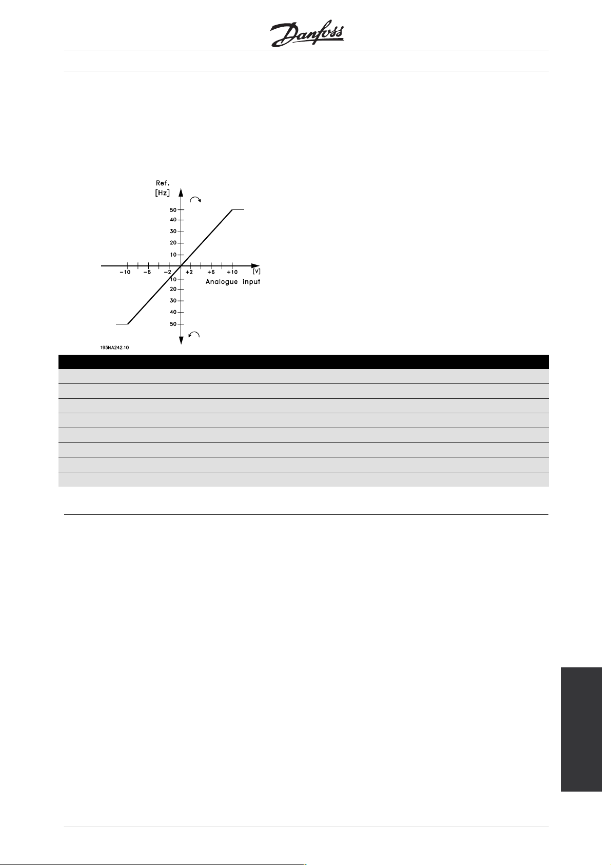
VLT®2800 / FCD 300 DeviceNet
Example,0-±10Volt:
External reference signal = 0 V (min) ± 10 V (max)
Reference = 50 Hz ccw - 50 Hz cw
Configuration (parameter 100) = Speed control, open loop
Setting:
Parameter: Setting: Data value:
100 Configuration Speed control, open loop [0]
308 Funct. of analogue input Reference [1]
309 Min. reference signal Min. 0 V
310 Max. reference signal Max. 10 V
203 Reference range Reference range - Max - + Max [1]
205 Max. reference 50 Hz
200 Output frequency range/direction Both directions, 0-132 Hz [1]
MG.90.B2.02 - VLT is a registered Danfoss trade mark
Additional control
features for VLT 2800
63
 Loading...