

Page 1
Operating Guide
VLT® Micro Drive FC 51
vlt-drives.danfoss.com
Page 2

Page 3

VLT® Micro Drive FC 51
Operating Guide
Contents
1
Introduction 5
1.1
Purpose of this Operating Guide 5
Additional Resources 5
1.2
Type Approvals and Certifications 5
1.3
1.4
IT Mains 5
1.5
Disposal 5
1.6
CE Declaration 6
Safety 7
2
Safety Symbols 7
2.1
Qualified Personnel 7
2.2
Safety Precautions 7
2.3
Safety Instructions 9
2.4
Contents
Installation 10
3
Before Commencing Repair Work 10
3.1
3.2
Side-by-side Installation 10
3.3
Mechanical Dimensions 10
3.4
Electrical Installation in General 11
3.5
Fuses 11
3.5.1
Branch Circuit Protection 11
3.5.2
Short-circuit Protection 11
3.5.3
Overcurrent Protection 12
3.5.4
Non-UL Compliance 12
3.5.5
Recommendation of Fuses 12
3.6
Connecting to Mains and Motor 13
3.7
Control Terminals 13
3.8
Power Circuit 16
3.9
Load Sharing/Brake 16
4
Programming 18
4.1
Local Control Panel (LCP) 18
4.2
Programming on Automatic Motor Tuning (AMT) 19
4.2.1
Mode 1 19
4.2.2
Mode 2 19
5
Parameter Overview 20
5.1
Parameter List 20
AQ276736419659en-000101/132R0029 | 3Danfoss A/S © 2021.05
Page 4

VLT® Micro Drive FC 51
Operating Guide
6
Troubleshooting 25
Warnings and Alarms 25
6.1
Specifications 27
7
Mains Supply 1x200–240 V AC 27
7.1
Mains Supply 3x200–240 V AC 27
7.2
Mains Supply 3x380–480 V AC 28
7.3
8
General Technical Data 31
8.1
Protection and Features 31
8.2
Mains Supply (L1/L, L2, L3/N) 31
8.3
Motor Output (U, V, W) 31
Cable Length and Cross-section 31
8.4
Digital Inputs (Pulse/encoder Inputs) 31
8.5
Analog Inputs 32
8.6
Contents
Analog Outputs 32
8.7
8.8
RS485 Serial Communication 32
8.9
Control Card, 24 V DC Output 32
8.10
Relay Output 32
8.11
Control Card, +10 V DC Output 33
8.12
Surroundings 33
9
Special Conditions 34
9.1
Derating for Ambient Temperature 34
9.2
Derating for Low Air Pressure 34
9.3
Derating for Running at Low Speeds 34
10
Options and Spare Parts 35
10.1
List of Options and Spare Parts 35
AQ276736419659en-000101/132R00294 | Danfoss A/S © 2021.05
Page 5
089
Do not dispose of equipment containing electrical components together with domestic waste.
Collect it separately in accordance with local and currently valid legislation.
VLT® Micro Drive FC 51
Operating Guide
Introduction
1 Introduction
1.1 Purpose of this Operating Guide
This Operating Guide provides information for safe installation and commissioning of the AC drive. It is intended for use by qualified
personnel.
Read and follow the instructions to use the drive safely and professionally.
Pay particular attention to the safety instructions and general warnings. Always keep this Operating Guide with the drive.
VLT® is a registered trademark for Danfoss A/S.
1.2 Additional Resources
Other resources are available to understand advanced drive functions and programming.
•
The Programming Guide provides greater detail on working with parameters and many application examples.
•
The Design Guide provides detailed information about capabilities and functionality to design motor control systems.
•
Instructions for operation with optional equipment and replacement of components.
Supplementary publications and manuals are available at:
1.3 Type Approvals and Certifications
www.danfoss.com.
For more information on UL 508C thermal memory retention requirements, refer to the section Motor Thermal Protection in the
product-specific Design Guide.
1.4 IT Mains
N O T I C E
IT MAINS
Installation on isolated mains source, that is IT mains. Maximum supply voltage allowed when connected to mains: 440 V.
As an option, Danfoss offers recommended line filters for improved harmonics performance. See chapter Options and Spare Parts.
1.5 Disposal
AQ276736419659en-000101 / 132R0029 | 5Danfoss A/S © 2021.05
Page 6
VLT® Micro Drive FC 51
Operating Guide
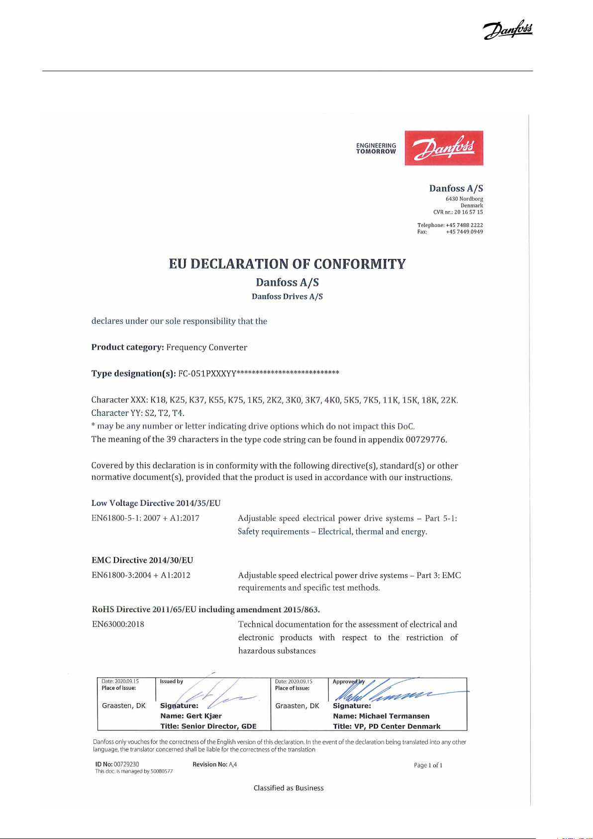
1.6 CE Declaration
Introduction
AQ276736419659en-000101 / 132R00296 | Danfoss A/S © 2021.05
Page 7
VLT® Micro Drive FC 51
Operating Guide
2 Safety
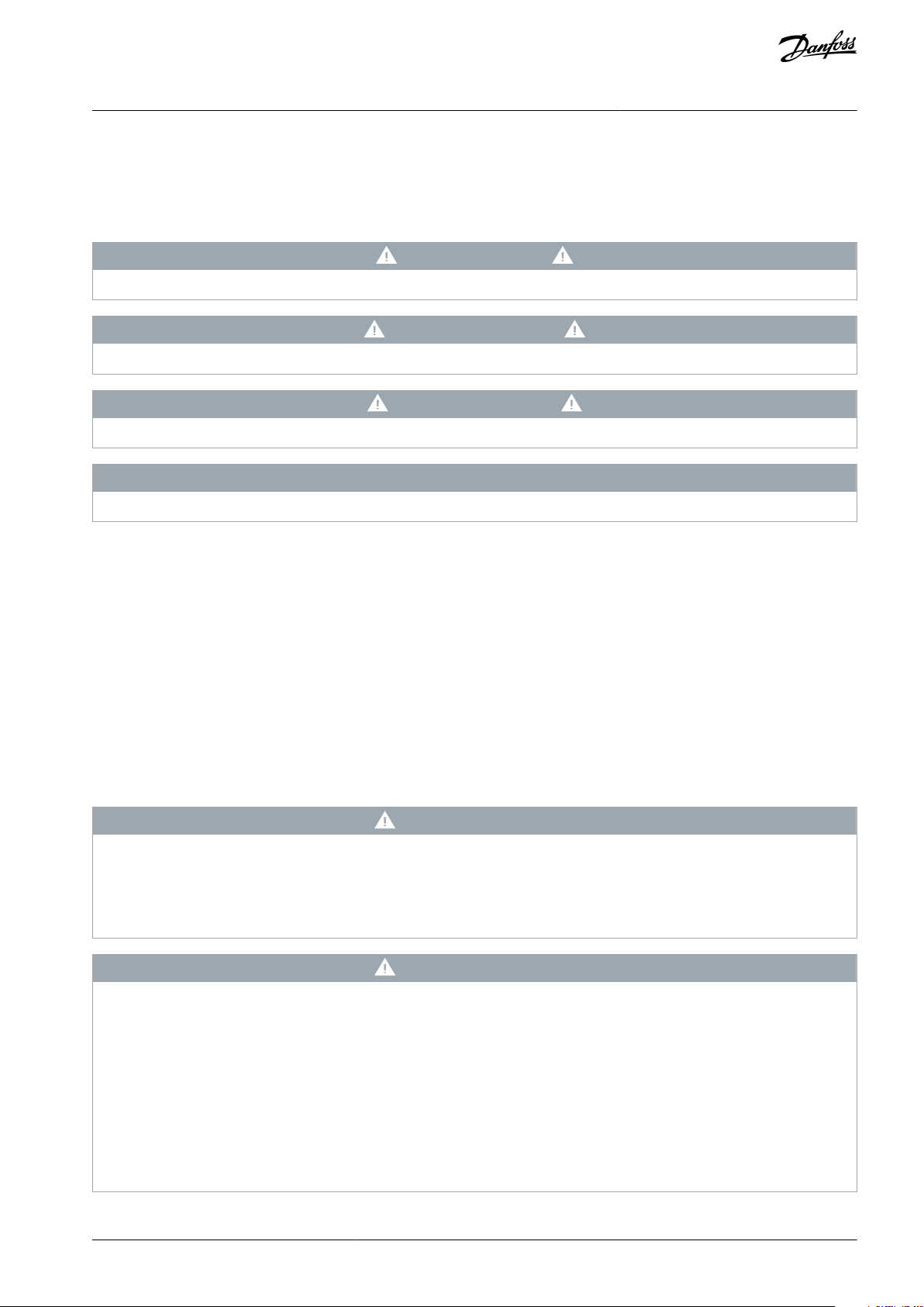
2.1 Safety Symbols
The following symbols are used in this manual:
D A N G E R
Indicates a hazardous situation which, if not avoided, will result in death or serious injury.
W A R N I N G
Indicates a hazardous situation which, if not avoided, could result in death or serious injury.
C A U T I O N
Indicates a hazardous situation which, if not avoided, could result in minor or moderate injury.
N O T I C E
Indicates information considered important, but not hazard-related (for example, messages relating to property damage).
Safety
2.2 Qualified Personnel
To allow trouble-free and safe operation of the unit, only qualified personnel with proven skills are allowed to transport, store, assemble, install, program, commission, maintain, and decommission this equipment.
Persons with proven skills:
•
Are qualified electrical engineers, or persons who have received training from qualified electrical engineers and are suitably
experienced to operate devices, systems, plant, and machinery in accordance with pertinent laws and regulations.
•
Are familiar with the basic regulations concerning health and safety/accident prevention.
•
Have read and understood the safety guidelines given in all manuals provided with the unit, especially the instructions given in
the Operating Guide.
•
Have good knowledge of the generic and specialist standards applicable to the specific application.
2.3 Safety Precautions
W A R N I N G
HIGH VOLTAGE
AC drives contain high voltage when connected to AC mains input, DC supply, or load sharing. Failure to perform installation,
start-up, and maintenance by qualified personnel can result in death or serious injury.
Only qualified personnel must perform installation, start-up, and maintenance.
-
W A R N I N G
UNINTENDED START
When the drive is connected to the AC mains, DC supply, or load sharing, the motor may start at any time, causing risk of death,
serious injury, and equipment or property damage. The motor may start by activation of an external switch, a fieldbus command,
an input reference signal from the LCP or LOP, via remote operation using MCT 10 Set-up software, or after a cleared fault condi-
tion.
Press [Off] on the LCP before programming parameters.
-
Disconnect the drive from the mains whenever personal safety considerations make it necessary to avoid unintended motor
-
start.
Check that the drive, motor, and any driven equipment are in operational readiness.
-
AQ276736419659en-000101 / 132R0029 | 7Danfoss A/S © 2021.05
Page 8
Size
Minimum waiting time (minutes)
M1, M2, and M3
4
M4 and M5
15
VLT® Micro Drive FC 51
Operating Guide
Safety
N O T I C E
The [Off/Reset] key is not a safety switch. It does not disconnect the drive from mains.
W A R N I N G
DISCHARGE TIME
The drive contains DC-link capacitors, which can remain charged even when the drive is not powered. High voltage can be
present even when the warning indicator lights are off.
Failure to wait the specified time after power has been removed before performing service or repair work could result in death or
serious injury.
Stop the motor.
-
Disconnect AC mains, permanent magnet type motors, and remote DC-link supplies, including battery back-ups, UPS, and
-
DC-link connections to other drives.
Wait for the capacitors to discharge fully. The minimum waiting time is specified in the table Discharge time and is also visible
-
on the nameplate on top of the drive.
Before performing any service or repair work, use an appropriate voltage measuring device to make sure that the capacitors
-
are fully discharged.
Table 1: Discharge Time
Leakage current (>3.5 mA)
Follow national and local codes regarding protective earthing of equipment with a leakage current >3.5 mA. AC drive technology
implies high frequency switching at high power. This generates a leakage current in the ground connection. A fault current in the
drive at the output power terminals might contain a DC component, which can charge the filter capacitors and cause a transient
ground current. The ground leakage current depends on various system configurations including RFI filtering, shielded motor cables, and drive power.
EN/IEC61800-5-1 (Power Drive System Product Standard) requires special care if the leakage current exceeds 3.5 mA. Reinforce
Grounding in 1 of the following ways:
•
Grounding wire of at least 10 mm2 (8 AWG).
•
2 separate ground wires both complying with the dimensioning rules.
See EN 60364-5-54 § 543.7 for further information.
Using RCDs
Where residual current devices (RCDs), also known as earth leakage circuit breakers (ELCBs), are used, comply with the following:
•
Use RCDs of type B that can detect AC and DC currents.
•
Use RCDs with an inrush delay to prevent faults due to transient ground currents.
•
Dimension RCDs according to the system configuration and environmental considerations.
Motor thermal protection
Motor overload protection is possible by setting parameter 1-90 Motor Thermal Protection to [4] ETR trip. For the North American
market: Implemented ETR function provides class 20 motor overload protection, in accordance with NEC.
Installation at high altitudes
For altitudes above 2000 m (6562 ft), contact Danfoss regarding PELV.
AQ276736419659en-000101 / 132R00298 | Danfoss A/S © 2021.05
Page 9

VLT® Micro Drive FC 51
Operating Guide
2.4 Safety Instructions
•
Make sure that the drive is properly grounded.
•
Do not remove mains connections, motor connections, or other power connections while the drive is connected to power.
•
Protect users against supply voltage.
•
Protect the motor against overloading according to national and local regulations.
Safety
AQ276736419659en-000101 / 132R0029 | 9Danfoss A/S © 2021.05
Page 10
B
a
A
a A
a A
a A
a A
C
C
C C
C
b
B
b
B
b
B
b
B
b
Ø 7mm
M5
M4
M3
M2
M1
Ø 7mm Ø 5.5mm Ø 4.5mm
e30bb321.11
Ø 4.5mm
Enclosure
Power [kW (hp)]
Height [mm (in)]
Width [mm (in)]
Depth
[mm
(in)]
(1)
Maximum
weight [kg
(lb)]
1x200–
240 V
3x200–
240 V
3x380–
480 V
A
A (including decoupling
plate)
aBb
C
M1
0.18–0.75
(0.24–1.0)
0.25–0.75
(0.34–1.0)
0.37–0.75
(0.5–1.0)
150
(5.9)
205 (8.1)
140.4
(5.5)70(2.8)55(2.2)
148 (5.8)
1.1 (2.4)
M2
1.5 (2.0)
1.5 (2.0)
1.5–2.2 (2.0–
3.0)
176
(6.9)
230 (9.1)
166.4
(6.6)75(3.0)59(2.3)
168 (6.6)
1.6 (3.5)
VLT® Micro Drive FC 51
Operating Guide
Installation
3 Installation
3.1 Before Commencing Repair Work
Procedure
1.
Disconnect the drive from mains (and external DC supply, if present).
2.
Wait for 4 minutes (M1, M2, and M3) and 15 minutes (M4 and M5) for discharge of the DC-link.
3.
Disconnect the DC bus terminals and the brake terminals (if present).
4.
Remove the motor cable.
3.2 Side-by-side Installation
The drive can be mounted side by side for IP20 rating units and requires 100 mm (3.9 in) clearance above and below for cooling.
Refer to chapter Specifications for details on environmental ratings of the drive.
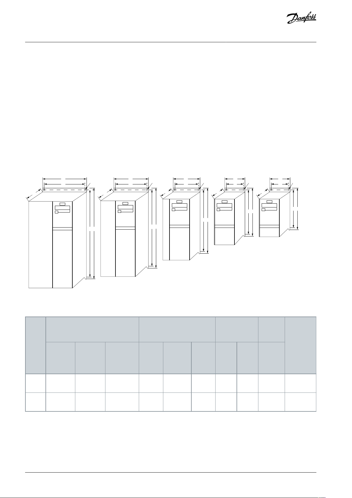
3.3 Mechanical Dimensions
A template for drilling is found on the flap of the packaging.
Illustration 1: Mechanical Dimensions
Table 2: Mechanical Dimensions
AQ276736419659en-000101 / 132R002910 | Danfoss A/S © 2021.05
Page 11
Enclosure
Power [kW (hp)]
Height [mm (in)]
Width [mm (in)]
Depth
[mm
(in)]
(1)
Maximum
weight [kg
(lb)]
1x200–
240 V
3x200–
240 V
3x380–
480 V
A
A (including decoupling
plate)
aBb
C
M3
2.2 (3.0)
2.2–3.7
(3.0–5.0)
3.0–7.5 (4.0–
10)
239
(9.4)
294 (11.6)
226
(8.9)90(3.5)69(2.7)
194 (7.6)
3.0 (6.6)
M4––
11.0–15.0
(15–20)
292
(11.5)
347.5
(13.7)
272.4
(10.7)
125
(4.9)97(3.8)
241 (9.5)
6.0 (13.2)
M5––
18.5–22.0
(25–30)
335
(13.2)
387.5
(15.3)
315
(12.4)
165
(6.5)
140
(5.5)
248 (9.8)
9.5 (20.9)
Power [kW (hp)]
Torque [Nm (in-lb)]
Enclosure
1x200–
240 V
3x200–
240 V
3x380–480 V
Line
Motor
DC connection/brake
Control
terminals
Ground
Relay
M1
0.18–0.75
(0.24–1.0)
0.25–0.75
(0.34–1.0)
0.37–0.75 (0.5–
1.0)
0.8 (7.1)
0.7 (6.2)
Spade
(1)
0.15 (1.3)
3 (26.6)
0.5 (4.4)
M2
1.5 (2.0)
1.5 (2.0)
1.5–2.2 (2.0–
3.0)
0.8 (7.1)
0.7 (6.2)
Spade
(1)
0.15 (1.3)
3 (26.6)
0.5 (4.4)
M3
2.2 (3.0)
2.2–3.7 (3.0–
5.0)
3.0–7.5 (4.0–
10)
0.8 (7.1)
0.7 (6.2)
Spade
(1)
0.15 (1.3)
3 (26.6)
0.5 (4.4)
M4––
11.0–15.0 (15–
20)
1.3 (11.5)
1.3 (11.5)
1.3 (11.5)
0.15 (1.3)
3 (26.6)
0.5 (4.4)
M5––
18.5–22.0 (25–
30)
1.3 (11.5)
1.3 (11.5)
1.3 (11.5)
0.15 (1.3)
3 (26.6)
0.5 (4.4)
VLT® Micro Drive FC 51
Operating Guide
1
For LCP with potentiometer, add 7.6 mm (0.3 in).
3.4 Electrical Installation in General
Installation
N O T I C E
All cabling must comply with national and local regulations on cable cross-sections and ambient temperature. Copper conduc-
tors required, 60–75 °C (140–167 °F) recommended.
Table 3: Tightening of Terminals
1
Spade connectors (6.3 mm (0.25 in) Faston plugs).
3.5 Fuses
3.5.1 Branch Circuit Protection
To prevent fire hazards, protect the branch circuits in an installation, switch gear, machines, and so on, against short circuits and
overcurrent. Follow national and local regulations.
3.5.2 Short-circuit Protection
Use the Danfoss recommended fuses to protect service personnel or other equipment if there is an internal failure in the unit or
short circuit on DC-link. If there is a short circuit on the motor or brake output, the drive provides full short-circuit protection.
AQ276736419659en-000101 / 132R0029 | 11Danfoss A/S © 2021.05
Page 12
FC 51
Maximum fuses UL
Maximum fuses non–
UL
Bussmann
Bussmann
Bussmann
Littelfuse
Ferraz Shawmut
Ferraz Shawmut
kW
Type RK1
Type J
Type T
Type RK1
Type CC
Type RK1
Type gG
1x200–240 V
PK18–PK37
KTN-R15
JKS-15
JJN-15
KLN-R15
ATM-R15
A2K-15R
16A
PK75
KTN-R25
JKS-25
JJN-25
KLN-R25
ATM-R25
A2K-25R
25A
P1K5
KTN-R35
JKS-35
JJN-35
KLN-R35
–
A2K-35R
35A
P2K2
KTN-R50
JKS-50
JJN-50
KLN-R50
–
A2K-50R
50A
3x200–240 V
PK25
KTN-R10
JKS-10
JJN-10
KLN-R10
ATM-R10
A2K-10R
10A
PK37
KTN-R15
JKS-15
JJN-15
KLN-R15
ATM-R15
A2K-15R
16A
PK75
KTN-R20
JKS-20
JJN-20
KLN-R20
ATM-R20
A2K-20R
20A
P1K5
KTN-R25
JKS-25
JJN-25
KLN-R25
ATM-R25
A2K-25R
25A
P2K2
KTN-R40
JKS-40
JJN-40
KLN-R40
ATM-R40
A2K-40R
40A
P3K7
KTN-R40
JKS-40
JJN-40
KLN-R40
–
A2K-40R
40A
3x380–480 V
PK37–PK75
KTS-R10
JKS-10
JJS-10
KLS-R10
ATM-R10
A6K-10R
10A
P1K5
KTS-R15
JKS-15
JJS-15
KLS-R15
ATM-R15
A2K-15R
16A
P2K2
KTS-R20
JKS-20
JJS-20
KLS-R20
ATM-R20
A6K-20R
20A
P3K0
KTS-R40
JKS-40
JJS-40
KLS-R40
ATM-R40
A6K-40R
40A
P4K0
KTS-R40
JKS-40
JJS-40
KLS-R40
ATM-R40
A6K-40R
40A
P5K5
KTS-R40
JKS-40
JJS-40
KLS-R40
–
A6K-40R
40A
P7K5
KTS-R40
JKS-40
JJS-40
KLS-R40
–
A6K-40R
40A
P11K
KTS-R60
JKS-60
JJS-60
KLS-R60
–
A6K-60R
63A
VLT® Micro Drive FC 51
Operating Guide
Installation
3.5.3 Overcurrent Protection
To avoid overheating of the cables in the installation, provide overload protection. Always carry out overcurrent protection according to national regulations. Fuses must be designed for protection in a circuit capable of supplying a maximum of 100000 A
(symmetrical), 480 V maximum.
rms
3.5.4 Non-UL Compliance
If UL/cUL is not to be complied with, use the fuses mentioned in this chapter, which ensure compliance with EN50178/IEC61800-5-1.
If there is a malfunction, not following the fuse recommendation may result in damage to the drive and the installation.
3.5.5 Recommendation of Fuses
Table 4: Fuses
AQ276736419659en-000101 / 132R002912 | Danfoss A/S © 2021.05
Page 13
FC 51
Maximum fuses UL
Maximum fuses non–
UL
P15K
KTS-R60
JKS-60
JJS-60
KLS-R60
–
A6K-60R
63A
P18K
KTS-R60
JKS-60
JJS-60
KLS-R60
–
A6K-60R
80A
P22K
KTS-R60
JKS-60
JJS-60
KLS-R60
–
A6K-60R
80A
e30ba472.10
VLT® Micro Drive FC 51
Operating Guide
Installation
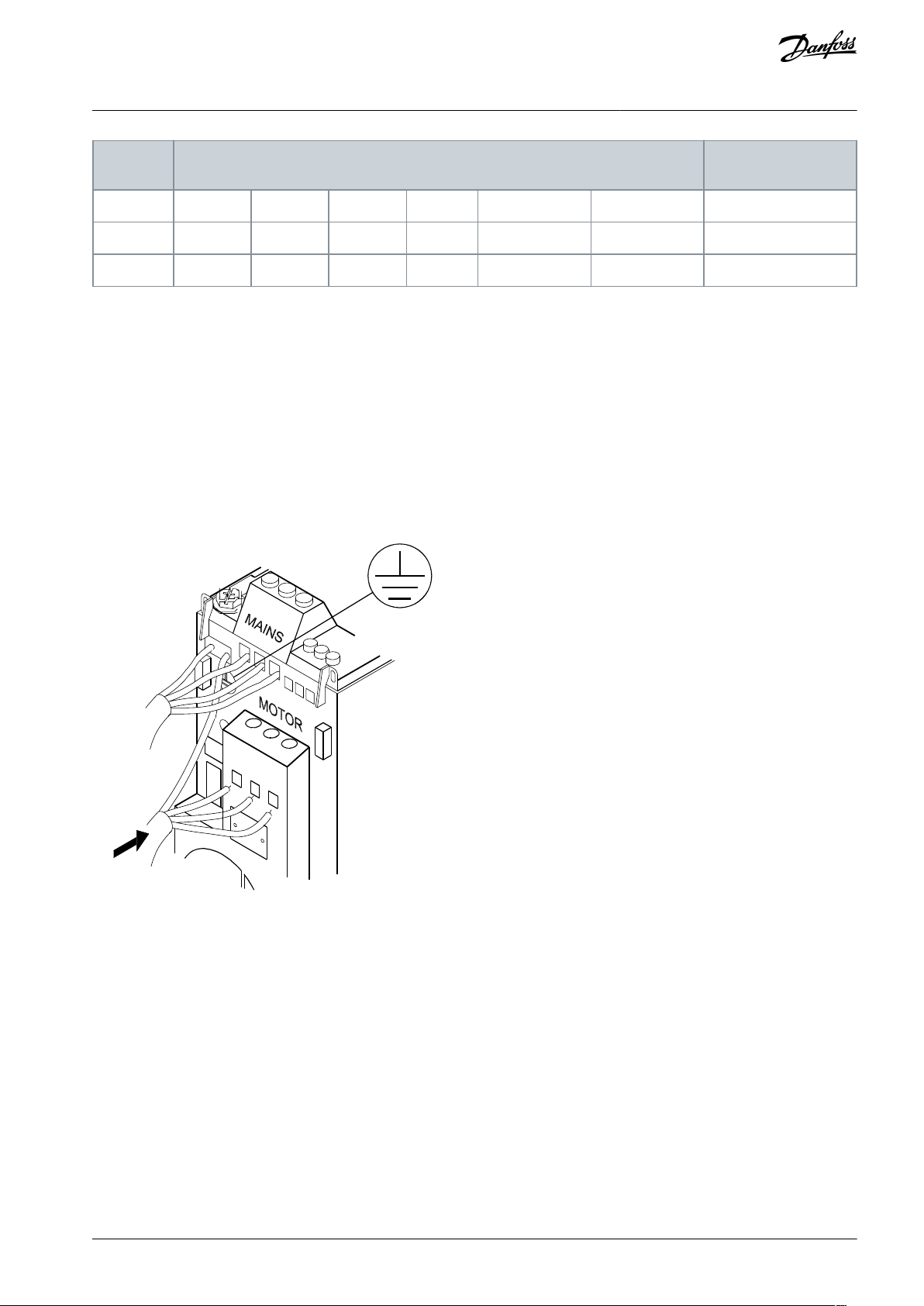
3.6 Connecting to Mains and Motor
The drive is designed to operate all standard 3-phased asynchronous motors.
The drive is designed to accept mains/ motor cables with a maximum cross-section of 4 mm2/10 AWG (M1, M2, and M3), and a
maximum cross-section of 16 mm2/6 AWG (M4 and M5).
•
Use a shielded/armored motor cable to comply with EMC emission specifications, and connect this cable to both the decoupling plate and the motor metal.
•
Keep motor cable as short as possible to reduce the noise level and leakage currents.
•
For further details on mounting of the decoupling plate, see VLT® Micro Drive FC 51 Decoupling Mounting Plate Instructions.
•
Also see the chapter EMC-correct Electrical Installation in the VLT® Micro Drive FC 51 Design Guide.
Mounting of Ground Cable, Mains, and Motor Wires
Illustration 2: Mounting of Ground Cable, Mains, and Motor Wires
•
Mount the ground wires to the PE terminal.
•
Connect motor to terminals U, V, and W.
•
Mount mains supply to terminals L1/L, L2, and L3/N (3-phase) or L1/L and L3/N (single-phase) and tighten.
3.7 Control Terminals
All control cable terminals are located underneath the terminal cover in front of the drive. Remove the terminal cover using a screwdriver.
AQ276736419659en-000101 / 132R0029 | 13Danfoss A/S © 2021.05
Page 14

e30ba477.11
Switch 1
Off=PNP terminals 29
(1)
On=NPN terminals 29
Switch 2
Off=PNP terminal 18, 19, 27, and 33
(1)
On=NPN terminal 18, 19, 27, and 33
Switch 3
No function
Switch 4
Off=Terminal 53 0–10 V
(1)
On=Terminal 53 0/4-20 mA
VLT® Micro Drive FC 51
Operating Guide
Illustration 3: Removing Terminal Cover
Installation
N O T I C E
See the back of the terminal cover for outlines of control terminals and switches.
N O T I C E
Do not operate switches with power on the drive.
N O T I C E
Set parameter 6-19 Terminal 53 Mode according to Switch 4 position.
Table 5: Settings for S200 Switches 1–4
1
This is the default setting.
AQ276736419659en-000101 / 132R002914 | Danfoss A/S © 2021.05
Page 15

e30ba474.10
ON
OFF
1 2 43
PNP/NPN
PNP/NPN
U/I
e30ba473.10
Com RS 485
P RS 485
N RS 485
+24 V OUT
A IN
D IN
D IN
D IN
D IN
D IN
Start
Reverse
Reset
Jog
Preset bit 0
GND
0/4 - 20 mA Output
A OUT
GND
0 -10 V A IN
1K Ohm
+10 V OUT
0/4 - 20 mA Input
+24 V
GND
GND
PNU 5 - 10
PNU 5 - 11
PNU 5 - 12
PNU 5 - 13
PNU 5 - 15
PNU 6 - 9*
PNU 6 - 1*
PNU 6 - 2*
+10 V DC
61
68 69
12 18
19 20
27
29 33
42
50 53 55
60
VLT® Micro Drive FC 51
Operating Guide
Illustration 4: S200 Switches 1–4
The following illustration shows all control terminals of the drive. Applying start (terminal 18) and an analog reference (terminal 53
or 60) make the drive run.
Installation
Illustration 5: Overview of Control Terminals in PNP-configuration with Factory Setting
AQ276736419659en-000101 / 132R0029 | 15Danfoss A/S © 2021.05
Page 16

e30ba242.18
+ 10 V DC
0-10 V DC 0/4-20 mA
0/4-20 mA
Analog output
0/4-20 mA
50 (+10 V OUT)
53 (A IN)
60 (A IN)
55 (COM A IN/OUT)
42 (A OUT)
12 (+24 V OUT)
18 (D IN)
19 (D IN)
20 (COM D IN)
27 (D IN)
29 (D IN)
33 (D IN)
ON/I=0-20 mA
OFF/U=0-10 V
S200
S200
ON (NPN)
OFF (PNP)
24 V
0 V
(NPN)
(PNP)
24 V
0 V
(NPN)
(PNP)
24 V
0 V
(NPN)
(PNP)
24 V
0 V
(NPN)
(PNP)
24 V
0 V
(NPN)
(PNP)
RS485
interface
(N RS485) 69
(P RS485) 68
(COM RS485) 61
RS485
(PNP) = Source
(NPN) = Sink
S801
0 V
S640
ON = Terminated
OFF = Open
Relay 1
03
02
01
240 V AC, 2 A
Brake
resistor
1)
DC bus
Motor
UDC-
UDC+/BR+
BR-
PE
U
V
W
Switch mode
power supply
10 V DC 24 V DC
5 V
3 phase
power
input
L1/L
L2
L3/N
PE
4
ON
1 2
ON
1 2
ON
VLT® Micro Drive FC 51
Operating Guide
3.8 Power Circuit
Installation
Illustration 6: Diagram Showing all Electrical Terminals
1) Brakes (BR+ and BR-) are not applicable for enclosure size M1.
For information about brake resistors, see VLT® Brake Resistor MCE 101 Design Guide.
Improved power factor and EMC performance can be achieved by installing optional Danfoss line filters.
Danfoss power filters can also be used for load sharing. For more information about load sharing, see VLT® Micro Drive FC 51 Load
Sharing application note.
3.9 Load Sharing/Brake
Use 6.3 mm (0.25 in) insulated Faston plugs designed for high voltage for DC (load sharing and brake).
Contact Danfoss or see Load sharing instruction VLT® 5000 for load sharing and VLT® 2800/5000/5000 FLUX/FCD 300 Brake for
brake.
Load sharing
Connect terminals -UDC and +UDC/+BR.
Brake
Connect terminals -BR and +UDC/+BR (not applicable for enclosure size M1).
AQ276736419659en-000101 / 132R002916 | Danfoss A/S © 2021.05
Page 17

VLT® Micro Drive FC 51
Operating Guide
N O T I C E
Voltage levels of up to 850 V DC may occur between terminals +UDC/+BR and -UDC. Not short-circuit protected.
Installation
AQ276736419659en-000101 / 132R0029 | 17Danfoss A/S © 2021.05
Page 18

e30ba605.13
1
2
3
4
5
6
7
8
9
10
11
12
Status
Quick
Menu
Main
Menu
Menu
On
Warn
Alarm
Hand
On
Off
Reset
Auto
On
Back
OK
Setup 1
1
Set-up number
2
Parameter number
3
Motor direction
4
Menu key
5
Indicator lights
6
Operation keys and LED
7
Potentiometer (LCP 12)
8
Navigation keys
9
Selected menu
10
Unit11Numeric display
12
Value
VLT® Micro Drive FC 51
Operating Guide
4 Programming
4.1 Local Control Panel (LCP)
For detailed information on programming, see VLT® Micro Drive FC 51 Programming Guide.
N O T I C E
The drive can also be programmed from a PC via RS485 com-port by installing the MCT 10 Set-up Software.
This software can either be ordered using code number 130B1000 or downloaded from the Danfoss web site: www.dan-
-
foss.com.
Programming
Illustration 7: Description of LCP Keys and Display
Press [Menu] to select 1 of the following menus:
Status
For readouts only.
Quick Menu
For access to Quick Menus 1 and 2.
Main Menu
For access to all parameters.
Navigation keys
[Back]: For moving to the previous step or layer in the navigation structure.
[▵] [▿]: For manoeuvring between parameter groups, parameters, and within parameters.
[OK]: For selecting a parameter and for accepting changes to parameter settings.
AQ276736419659en-000101 / 132R002918 | Danfoss A/S © 2021.05
Page 19

VLT® Micro Drive FC 51
Operating Guide
Pressing [OK] for more than 1 s enters Adjust mode. In Adjust mode, it is possible to make fast adjustment by pressing [▵] [▿] combined with [OK].
Press [▵] [▿] to change value. Press [OK] to shift between digits quickly.
To exit Adjust mode, press [OK] more than 1 s again with changes saving or press [Back] without changes saving.
Operation keys
A yellow indicator light above the operation keys indicates the active key.
[Hand On]: Starts the motor and enables control of the drive via the LCP.
[Off/Reset]: The motor stops. If in alarm mode, the motor resets.
[Auto On]: The drive is controlled either via control terminals or serial communication.
[Potentiometer] (LCP12): The potentiometer works in 2 ways depending on the mode in which the drive is running.
In auto-on mode, the potentiometer acts as an extra programmable analog input.
In hand-on mode, the potentiometer controls local reference.
Programming
4.2 Programming on Automatic Motor Tuning (AMT)
Run AMT to optimize compatibility between the drive and the motor in VVC+ mode.
The drive builds a mathematical model of the motor for regulating output motor current thus enhancing motor performance.
•
Run this procedure on a cold motor for best results. To run AMT, use the numeric LCP (NLCP). There are 2 AMT modes for drives.
•
N O T I C E
In mode 2, the rotor rotates during the AMT progress.
Do not add any load on the motor in this AMT progress.
-
4.2.1 Mode 1
Procedure
1.
Enter the main menu.
2.
Go to parameter group 1-** Load and Motor.
3.
Press [OK].
4.
Set motor parameters using nameplate data for parameter group 1-2* Motor Data.
5.
Go to parameter 1-29 Automatic Motor Tuning (AMT).
Press [OK].
6.
7.
Select [2] Enable AMT.
Press [OK].
8.
The test runs automatically and indicates when it is complete.
9.
4.2.2 Mode 2
Procedure
Enter the main menu.
1.
2.
Go to parameter group 1-** Load and Motor.
Press [OK].
3.
4.
Set motor parameters using nameplate data for parameter group 1-2* Motor Data.
5.
Go to parameter 1-29 Automatic Motor Tuning (AMT).
Press [OK].
6.
7.
Select [3] Complete AMT with Rotating motor.
Press [OK].
8.
The test runs automatically and indicates when it is complete.
9.
AQ276736419659en-000101 / 132R0029 | 19Danfoss A/S © 2021.05
Page 20

0-** Operation/Display
0-0* Basic Settings
0-03 Regional Settings
*[0] International
[1] US
0-04 Operating State at Pow-
er-up (Hand)
[0] Resume
*[1] Forced stop, ref=old
[2] Forced stop, ref=0
0-1* Set-up Operations
0-10 Active Set-up
*[1] Set-up 1
[2] Set-up 2
[9] Multi Set-up
0-11 Edit Set-up
*[1] Set-up 1
[2] Set-up 2
[9] Active Set-up
0-12 Link Setups
[0] Not Linked
*[20] Linked
0-3* LCP Readout
0-31 Custom Readout Min
Value
0.00–9999.00 * 0.00
0-32 Custom Readout Max
Value
0.00–9999.00 * 100.0
0-4* LCP Keypad
0-40 [Hand on] Key on LCP
[0] Disabled
*[1] Enabled
0-41 [Off / Reset] Key on LCP
[0] Disable All
*[1] Enable All
[2] Enable Reset Only
0-42 [Auto on] Key on LCP
[0] Disabled
*[1] Enabled
0-5* Copy/Save
0-50 LCP Copy
*[0] No copy
[1] All to LCP
[2] All from LCP
[3] Size indep. from LCP
0-51 Set-up Copy
*[0] No copy
[1] Copy from set-up 1
[2] Copy from set-up 2
[9] Copy from Factory set-up
0-6* Password
0-60 Main/Quick Menu Pass-
word
0–999 *0
0-61 Access to Main/Quick
Menu w/o Password
*[0] Full access
[1] LCP:Read Only
[2] LCP:No Access
1-** Load and Motor
1-0* General Settings
1-00 Configuration Mode
*[0] Speed open loop
[3] Process
1-01 Motor Control Principle
[0] U/f
*[1] VVC+
1-03 Torque Characteristics
*[0] Constant torque
[2] Auto Energy Optimization
1-05 Hand Mode Configura-
tion
[0] Speed Open Loop
*[2] As mode par 1-00
1-2* Motor Data
1-20 Motor Power
[1] 0.09 kW-0.12 hp
[2] 0.12 kW-0.16 hp
[3] 0.18 kW-0.25 hp
[4] 0.25 kW-0.33 hp
[5] 0.37 kW-0.50 hp
[6] 0.55 kW-0.75 hp
[7] 0.75 kW-1.00 hp
[8] 1.10 kW-1.50 hp
[9] 1.50 kW-2.00 hp
[10] 2.20 kW-3.00 hp
[11] 3.00 kW-4.00 hp
[12] 3.70 kW-5.00 hp
[13] 4.00 kW-5.40 hp
[14] 5.50 kW-7.50 hp
[15] 7.50 kW-10.00 hp
[16] 11.00 kW-15.00 hp
[17] 15.00 kW-20.00 hp
[18] 18.50 kW-25.00 hp
[19] 22.00 kW-30.00 hp
[20] 30.00 kW-40.00 hp
1-22 Motor Voltage
50-999 V *Motortype dep.
1-23 Motor Frequency
20–400 Hz *Motortype dep.
1-24 Motor Current
0.01–26.00 A *Motortype dep.
1-25 Motor Nominal Speed
100–9999 rpm *Motortype
dep.
1-29 Automatic Motor Tuning
(AMT)
*[0] Off
[2] Enable AMT
[3] Complete AMT with Rotat-
ing motor
1-3* Adv. Motor Data
1-30 Stator Resistance (Rs)
[Ohm] * Dep. on motor data
1-33 Stator Leakage Reac-
tance (X1)
[Ohm] * Dep. on motor data
1-35 Main Reactance (Xh)
[Ohm] * Dep. on motor data
1-5* Load Indep. Setting
1-50 Motor Magnetisation at
Zero Speed
0–300% *100%
1-52 Min Speed Normal Mag-
netising [Hz]
0.0–10.0 Hz *0.0Hz
1-55 U/f Characteristic - U
0-999.9 V *0 V
1-56 U/f Characteristic - F
0-1000 Hz *0 Hz
1-6* Load Depen. Setting
1-60 Low Speed Load Com-
pensation
0–199% *100%
1-61 High Speed Load Com-
pensation
0–199% *100%
1-62 Slip Compensation
-400–399% *100%
1-63 Slip Compensation Time
Constant
0.05–5.00 s *0.10 s
1-7* Start Adjustments
1-71 Start Delay
0.0–10.0 s *0.0 s
1-72 Start Function
[0] DC hold/delay time
[1] DC brake/delay time
*[2] Coast/delay time
1-73 Flying Start
*[0] Disabled
[1] Enabled
1-8* Stop Adjustments
1-80 Function at Stop
*[0] Coast
[1] DC hold
1-82 Min Speed for Function
at Stop [Hz]
0.0–20.0 Hz *0.0 Hz
1-9*Motor Temperature
1-90 Motor Thermal Protec-
tion
*[0] No protection
[1] Thermistor warning
[2] Thermistor trip
[3] ETR warning 1
[4] ETR trip 1
1-93 Thermistor Resource
*[0] None
[1] Analog input 53
[6] Digital input 29
2-** Brakes
2-0* DC-Brake
2-00 DC Hold Current
0–150% *50%
2-01 DC Brake Current
0–150% *50%
2-02 DC Braking Time
0.0–60.0 s *10.0 s
2-04 DC Brake Cut In Speed
0.0–400.0 Hz *0.0Hz
2-1* Brake Energy Funct.
2-10 Brake Function
*[0] Off
[1] Resistor brake
[2] AC brake
2-11 Brake Resistor (ohm)
VLT® Micro Drive FC 51
Operating Guide
5 Parameter Overview
5.1 Parameter List
Table 6: Parameter List
Parameter Overview
AQ276736419659en-000101 / 132R002920 | Danfoss A/S © 2021.05
Page 21

Min/Max/default: Powersize
dep.
2-14 Brake Voltage reduce
0-100 *0
2-16 AC Brake, Max current
0-150% *100%
2-17 Overvoltage Control
*[0] Disabled
[1] Enabled (not at stop)
[2] Enabled
2-2* Mechanical Brake
2-20 Release Brake Current
0.00–100.0 A *0.00 A
2-22 Activate Brake Speed
[Hz]
0.0–400.0 Hz *0.0 Hz
3-** Reference / Ramps
3-0* Reference Limits
3-00 Reference Range
*[0] Min - Max
[1] -Max - +Max
3-02 Minimum Reference
-4999–4999 *0.000
3-03 Maximum Reference
-4999–4999 *50.00
3-1* References
3-10 Preset Reference
-100.0–100.0% *0.00%
3-11 Jog Speed [Hz]
0.0–400.0 Hz *5.0 Hz
3-12 Catch up/slow Down Val-
ue
0.00–100.0% * 0.00%
3-14 Preset Relative Reference
-100.0–100.0% *0.00%
3-15 Reference Resource 1
[0] No function
*[1] Analog Input 53
[2] Analog input 60
[8] Pulse input 33
[11] Local bus reference
[21] LCP Potentiometer
3-16 Reference Resource 2
[0] No function
[1] Analog in 53
*[2] Analog in 60
[8] Pulse input 33
[11] Local bus reference
[21] LCP Potentiometer
3-17 Reference Resource 3
[0] No function
[1] Analog Input 53
[2] Analog input 60
[8] Pulse input 33
*[11] Local bus reference
[21] LCP Potentiometer
3-18 Relative Scaling Refer-
ence Resource
*[0] No function
[1] Analog in 53
[2] Analog in 60
[8] Pulse input 33
[11] Local bus reference
[21] Lcp Potentiometer
3-4* Ramp 1
3-40 Ramp 1 Type
*[0] Linear
[2] Sine2 ramp
3-41 Ramp 1 Ramp up Time
0.05–3600 s *3.00 s (10.00 s)
(1)
3-42 Ramp 1 Ramp Down
Time
0.05–3600 s *3.00s (10.00s)
(1)
3-5* Ramp 2
3-50 Ramp 2 Type
*[0] Linear
[2] Sine2 ramp
3-51 Ramp 2 Ramp up Time
0.05–3600 s *3.00s (10.00s)
(1)
3-52 Ramp 2 Ramp down
Time
0.05–3600 s *3.00s (10.00s)
(1)
3-8* Other Ramps
3-80 Jog Ramp Time
0.05–3600 s *3.00s (10.00s)
(1)
3-81 Quick Stop Ramp Time
0.05–3600 s *3.00 s (10.00s)
(1)
4-** Limits/Warnings
4-1* Motor Limits
4-10 Motor Speed Direction
[0] Clockwise
[1] Counter clockwise
*[2] Both directions
4-12 Motor Speed Low Limit
[Hz]
0.0–400.0 Hz *0.0 Hz
4-14 Motor Speed High Limit
[Hz]
0.1–400.0 Hz *65.0 Hz
4-16 Torque Limit Motor
Mode
0–400% *150%
4-17 Torque Limit Generator
Mode
0–400% *100%
4-4* Adj. Warnings 2
4-40 Warning Freq. Low
0.00–Value of 4-41 Hz *0.0 Hz
4-41 Warning Freq. High
Value of 4-40–400.0 Hz
*400.00 Hz
4-5* Adj. Warnings
4-50 Warning Current Low
0.00–100.00 A *0.00 A
4-51 Warning Current High
0.0–100.00 A *100.00 A
4-54 Warning Reference Low
-4999.000–Value of 4-55 *
-4999.000
4-55 Warning Reference High
Value of 4-54–4999.000
*4999.000
4-56 Warning Feedback Low
-4999.000–Value of 4-57 *
-4999.000
4-57 Warning Feedback High
Value of 4-56–4999.000
*4999.000
4-58 Missing Motor Phase
Function
[0] Off
*[1] On
4-6* Speed Bypass
4-61 Bypass Speed From [Hz]
0.0–400.0 Hz *0.0 Hz
4-63 Bypass Speed To [Hz]
0.0–400.0 Hz *0.0 Hz
5-** Digital In/Out
5-1* Digital Inputs
5-10 Terminal 18 Digital Input
[0] No function
[1] Reset
[2] Coast inverse
[3] Coast and reset inverse
[4] Quick stop inverse
[5] DC-brake inverse
[6] Stop inverse
*[8] Start
[9] Latched start
[10] Reversing
[11] Start reversing
[12] Enable start forward
[13] Enable start reverse
[14] Jog
[16-18] Preset ref bit 0-2
[19] Freeze reference
[20] Freeze output
[21] Speed up
[22] Speed down
[23] Set-up select bit 0
[28] Catch up
[29] Slow down
[34] Ramp bit 0
[60] Counter A (up)
[61] Counter A (down)
[62] Reset counter A
[63] Counter B (up)
[64] Counter B (down)
[65] Reset counter B
5-11 Terminal 19 Digital Input
See par. 5-10. * [10] Reversing
5-12 Terminal 27 Digital Input
See par. 5-10. * [1] Reset
5-13 Terminal 29 Digital Input
See par. 5-10. * [14] Jog
5-15 Terminal 33 Digital Input
See par. 5-10. * [16] Preset ref
bit 0
[26] Precise Stop Inverse
[27] Start, Precise Stop inverse
[32] Pulse Input
5-3* Digital Outputs
5-34 On Delay, Terminal 42
Digital Output
0.00–600.00 s * 0.01 s
5-35 Off Delay, Terminal 42
Digital Output
0.00–600.00 s * 0.01 s
5-4* Relays
5-40 Function Relay
*[0] No operation
[1] Control ready
[2] Drive ready
VLT® Micro Drive FC 51
Operating Guide
Table 7: Parameter List
1
M4 and M5 only.
Parameter Overview
AQ276736419659en-000101 / 132R0029 | 21Danfoss A/S © 2021.05
Page 22

[3] Drive ready/remote control
[4] Enable/no warning
[5] VLT running
[6] Running/no warning
[7] Run in range/no warning
[8] Run on ref/no warning
[9] Alarm
[10] Alarm or warning
[12] Out of current range
[13] Below current, low
[14] Above current, high
[16] Below frequency, low
[17] Above frequency, high
[19] Below feedback, low
[20] Above feedback, high
[21] Thermal warning
[22] Ready, no thermal warn-
ing
[23] Remote ready, no ther-
mal warning
[24] Ready, Voltage OK
[25] Reverse
[26] Bus OK
[28] Brake, no brake warning
[29] Brake ready, no fault
[30] BrakeFault (IGBT)
[32] Mech brake control
[36] Control word bit 11
[41] Below reference, low
[42] Above reference, high
[51] Local ref. active
[52] Remote ref. active
[53] No alarm
[54] Start command activ
[55] Running reverse
[56] Drive in hand mode
[57] Drive in auto mode
[60-63] Comparator 0-3
[70-73] Logic rule 0-3
[81] SL digital output B
5-41 On Delay, Relay
0.00–600.00 s *0.01 s
5-42 Off Delay, Relay
0.00–600.00 s *0.01 s
5-5* Pulse Input
5-55 Terminal 33 Low Fre-
quency
20–4999 Hz *20 Hz
5-56 Terminal 33 High Fre-
quency
21–5000 Hz *5000 Hz
5-57 Terminal 33 Low Ref./
Feedb. Value
-4999–4999 *0.000
5-58 Terminal 33 High Ref./
Feedb. Value
-4999–4999 *50.000
6-** Analog In/Out
6-0* Analog I/O Mode
6-00 Live Zero Timeout Time
1-99 s *10 s
6-01 Live Zero TimeoutFunc-
tion
*[0] Off
[1] Freeze output
[2] Stop
[3] Jogging
[4] Max. speed
[5] Stop and trip
6-1* Analog Input 1
6-10 Terminal 53 Low Voltage
0.00–10.00 V *0.07 V
6-11 Terminal 53 High Volt-
age
0.01–10.00 V *10.00 V
6-12 Terminal 53 Low Current
0.00-20.00 *0.14
6-13 Terminal 53 High Current
0.01–20.00 mA *20.00 mA
6-14 Terminal 53 Low Ref./
Feedb. Value
-4999-4999 *0.000
6-15 Terminal 53 High Ref./
Feedb. Value
-4999-4999 *50.000
6-16 Terminal 53 Filter Time
Constant
0.01–10.00 s *0.01 s
6-19 Terminal 53 mode
*[0] Voltage mode
[1] Current mode 4
6-2* Analog Input 2
6-21 Reserved for testing
0-1 *0
6-22 Terminal 60 Low Current
0.00–20.00 mA *0.14 mA
6-23 Terminal 60 High Current
0.00–20.00 mA *20.00 mA
6-24 Terminal 60 Low Ref./
Feedb. Value
-4999-4999 *0.000
6-25 Terminal 60 High Ref./
Feedb. Value
-4999–4999 *50.00
6-26 Terminal 60 Filter Time
Constant
0.01–10.00 s *0.01 s
6-8* LCP potmeter
6-80 LCP Potmeter Enable
[0] Disabled
*[1] Enable
6-81 LCP potmeter Low Ref.
-4999–4999 *0.000
6-82 LCP potmeter High Ref.
-4999–4999 *50.00
6-9* Analog Output xx
6-90 Terminal 42 Mode
*[0] 0-20 mA
[1] 4-20 mA
[2] Digital Output
6-91 Terminal 42 Analog Out-
put
*[0] No operation
[10] Output Frequency
[11] Reference
[12] Feedback
[13] Motor Current
[16] Power
[19] DC Link Voltage
[20] Bus Reference
6-92 Terminal 42 Digital Out-
put
See parameter 5-40
*[0] No Operation
[80] SL Digital Output A
6-93 Terminal 42 Output Min
Scale
0.00-200.0% *0.00%
6-94 Terminal 42 Output Max
Scale
0.00-200.0% *100.0%
6-98 Drive Type
9-9 *9
7-** Controllers
7-2* Process Ctrl. Feedb
7-20 Process CL Feedback 1
Resource
*[0] No function
[1] Analog in 53
[2] Analog in 60
[8] Pulse input 33
[11] Local bus
7-3* Process PI Ctrl.
7-30 Process PI Normal/
Inverse Control
*[0] Normal
[1] Inverse
7-31 Process PI Anti Windup
[0] Disable
*[1] Enable
7-32 Process PI Start Speed
0.0–200.0 Hz *0.0 Hz
7-33 Process PI Proportional
Gain
0.00–10.00 *0.01
7-34 Process PI Integral Time
0.10–9999.00 s *9999.00 s
7-38 Process PI Feed Forward
Factor
0–400% *0%
7-39 On Reference Bandwidth
0–200% *5%
8-** Comm. and Options
8-0* Comm. General Settings
8-01 Control Site
*[0] Digital and ctrl.word
[1] Digital only
[2] Controlword only
8-02 Control Word Source
[0] None
*[1] FC RS485
8-03 Control Word Timeout
Time
0.1–6500.0 s *1.0 s
8-04 Control Word Timeout
Function
*[0] Off
[1] Freeze Output
[2] Stop
[3] Jogging
[4] Max. Speed
[5] Stop and trip
8-06 Reset Control Word
Timeout
*[0] No Function
[1] Do reset
8-3* FC Port Settings
8-30 Protocol
*[0] FC
[2] Modbus RTU
8-31 Address
1-247 *1
8-32 FC Port Baud Rate
[0] 2400 Baud
[1] 4800 Baud
VLT® Micro Drive FC 51
Operating Guide
Table 8: Parameter List
Parameter Overview
AQ276736419659en-000101 / 132R002922 | Danfoss A/S © 2021.05
Page 23

*[2] 9600 Baud
[3] 19200 Baud
[4] 38400 Baud
8-33 FC Port Parity
*[0] Even Parity, 1 Stop Bit
[1] Odd Parity, 1 Stop Bit
[2] No Parity, 1 Stop Bit
[3] No Parity, 2 Stop Bits
8-35 Minimum Response De-
lay
0.001–0.500 *0.010 s
8-36 Max Response Delay
0.100–10.000 s *5.000 s
8-4* FC MC protocol set
8-42 FC Port PCD Write Con-
figuration
*[0] None
[1] [302] Minimum Reference
[2] [303] Maximum Reference
[3] [312] Catch up/Slow Down
Value
[4] [341] Ramp 1 Ramp up
time
[5] [342] Ramp 1 Ramp down
time
[6] [351] Ramp 2 Ramp up
time
[7] [352] Ramp 2 Ramp down
time
[8] [380] Jog Ramp Time
[9] [381] Quick Stop Time
[10] [412] Motor Speed Low
Limit [Hz]
[11] [414] Motor Speed High
Limit [Hz]
[12] [416] Torque Limit Motor
Mode
[13] [417] Torque Limit Gener-
ator Mode
[14] FC Port CTW
[15] FC Port REF
8-43 FC Port PCD Read Con-
figuration
*[0] None
[1] [1500] Operation Hours
[2] [1501] Running Hours
[3] [1502] kWh Counter
[4] [1600] Control Word
[5] [1601] Reference [Unit]
[6] [1602] Reference %
[7] [1603] Status Word
[8] [1605] Main Actual Value
[%]
[9] [1609] Custom Readout
[10] [1610] Power [kW]
[11] [1611] Power [hp]
[12] [1612] Motor Voltage
[13] [1613] Frequency
[14] [1614] Motor Current
[15] [1615] Frequency [%]
[16] [1618] Motor Thermal
[17] [1630] DC Link Voltage
[18] [1634] Heatsink Temp.
[19] [1635] Inverter Thermal
[20] [1638] SL Controller State
[21] [1650] External Reference
[22] [1651] Pulse Reference
[23] [1652] Feedback [Unit]
[24] [1660] Digital Input 18,
19, 27, 33
[25] [1661] Digtial Input 29
[26] [1662] Analog Input 53
(V)
[27] [1663] Analog Input 53
(mA)
[28] [1664] Analog Input 60
[29] [1665] Analog Output 42
[mA]
[30] [1668] Freq. Input 33 [Hz]
[31] [1671] Relay Output [bin]
[32] [1672] Counter A
[33] [1673] Counter B
[34] [1690] Alarm Word
[35] [1692] Warning Word
[36] [1694] Ext. Status Word
8-5* Digital/Bus
8-50 Coasting Select
[0] DigitalInput
[1] Bus
[2] Logic AND
*[3] Logic OR
8-51 Quick Stop Select
See par. 8-50 * [3] Logic OR
8-52 DC Brake Select
See par. 8-50 *[3] Logic OR
8-53 Start Select
See par. 8-50 *[3] Logic OR
8-54 Reversing Select
See par. 8-50 *[3] Logic OR
8-55 Set-up Select
See par. 8-50 *[3] Logic OR
8-56 Preset Reference Select
See parameter 8-50 * [3] Logic
OR
8-8* FC Port Diagnostics
8-80 Bus Message Count
0-65535 *0
8-81 Bus Error Count
0-65535 *0
8-82 Slave Messages Rcvd
0-65535 *0
8-83 Slave Error Count
0-65535 *0
8-9* Bus Jog / Feedback
8-94 Bus feedback 1
-32768-32767 *0
13-** Smart Logic
13-0* SLC Settings
13-00 SL Controller Mode
*[0] Off
[1] On
13-01 Start Event
[0] False
[1] True
[2] Running
[3] In range
[4] On reference
[7] Out of current range
[8] Below I low
[9] Above I high
[16] Thermal warning
[17] Mains out of range
[18] Reversing
[19] Warning
[20] Alarm (trip)
[21] Alarm (triplock)
[22-25] Comparator 0-3
[26-29] Logic rule 0-3
[33] Digital input 18
[34] Digital input 19
[35] Digital input 27
[36] Digital input 29
[38] Digital input 33
*[39] Start command
[40] Drive stopped
13-02 Stop Event
See parameter 13-01
* [40] Drive stopped
13-03 Reset SLC
*[0] Do not reset
[1] Reset SLC
13-1* Comparators
13-10 Comparator Operand
*[0] Disabled
[1] Reference
[2] Feedback
[3] Motor speed
[4] Motor current
[6] Motor power
[7] Motor voltage
[8] DC-link voltage
[12] Analog in 53
[13] Analog in 60
[18] Pulse input 33
[20] Alarm number
[30] Counter A
[31] Counter B
13-11 Comparator Operator
[0] Less Than
*[1] Approx. Equal
[2] Greater Than
13-12 Comparator Value
-9999–9999 *0.0
13-2* Timers
13-20 SL Controller Timer
0.0–3600 s *0.0 s
13-4* Logic Rules
13-40 Logic Rule Boolean 1
See par. 13-01 *[0] False
[30] - [32] SL Time-out 0-2
13-41 Logic Rule Operator 1
*[0] Disabled
[1] AND
[2] OR
[3] AND NOT
[4] OR NOT
[5] NOT AND
[6] NOT OR
[7] NOT AND NOT
[8] NOT OR NOT
13-42 Logic Rule Boolean 2
See par. 13-40 * [0] False
13-43 Logic Rule Operator 2
See par. 13-41 *[0] Disabled
13-44 Logic Rule Boolean 3
See par. 13-40 * [0] False
13-5* States
13-51 SL Controller Event
See par. 13-40 *[0] False
13-52 SL Controller Action
*[0] Disabled
[1] No action
[2] Select set-up 1
[3] Select set-up 2
[10-17] Select preset ref 0-7
[18] Select ramp 1
VLT® Micro Drive FC 51
Operating Guide
Table 9: Parameter List
Parameter Overview
AQ276736419659en-000101 / 132R0029 | 23Danfoss A/S © 2021.05
Page 24

[19] Select ramp 2
[22] Run
[23] Run reverse
[24] Stop
[25] Qstop
[26] Dcstop
[27] Coast
[28] Freeze output
[29] Start timer 0
[30] Start timer 1
[31] Start timer 2
[32] Set digital output A low
[33] Set digital output B low
[38] Set digital output A high
[39] Set digital output B high
[60] Reset Counter A
[61] Reset Counter B
14-** Special Functions
14-0* Inverter Switching
14-01 Switching Frequency
[0] 2.0 kHz
*[1] 4.0 kHz
[2] 8.0 kHz
[4] 16.0 kHz
14-03 Overmodulation
[0] Off
*[1] On
14-1* Mains monitoring
14-12 Function at Mains Im-
balance
*[0] Trip
[1] Warning
[2] Disabled
14-2* Trip Reset
14-20 Reset Mode
*[0] Manual reset
[1-10] Automatic reset x (1-10)
[11] Automatic reset x 15
[12] Automatic reset x 20
[13] Infinite auto reset
[14] Reset at power-up
14-21 Automatic Restart Time
0–600s * 10s
14-22 Operation Mode
*[0] Normal Operation
[2] Initialisation
14-26 Action At Inverter Fault
[0] Trip
*[1] Warning
14-28 Production Settings
*[0] No action
[1] Service reset
14-29 Service Code
0-0x7FFFFFFF *0
14-4* Energy Optimising
14-41 AEO Minimum Magnet-
isation
40–75 %*66 %
14-9* Fault Settings
14-90 Fault level
*[3] Trip Lock
[4] Trip with delayed reset
15-** Drive Information
15-0* Operating Data
15-00 Operating Time
0-9999 *0
15-01 Running Hours
0-60000 *0
15-02 kWh Counter
0-65535 *0
15-03 Power Up's
0-2147483647 *0
15-04 Over Temp's
0-65535 *0
15-05 Over Volt's
0-65535 *0
15-06 Reset kWh Counter
*[0] Do not reset
[1] Reset counter
15-07 Reset Running Hours
Counter
*[0] Do not reset
[1] Reset counter
15-3* Fault Log
15-30 Fault Log: Error Code
0-255 *0
15-4* Drive Identification
15-40 FC Type
15-41 Power Section
15-42 Voltage
15-43 Software Version
15-46 Frequency Converter
Ordering No
15-48 LCP Id No
15-49 Software ID Control
Card
15-50 Software ID Power Card
15-51 Frequency Converter
Serial Number
15-9* Parameter Info
15-92 Parameter List
0-2000 *0
15-97 Application Type
0-0xFFFFFFFF *0
15-98 Drive Identification
String
16-** Data Readouts
16-0* General Status
16-00 Control Word
0-65535 *0
16-01 Reference [Unit]
-4999.000–4999.000 *0.000
16-02 Reference %
-200.0–200.0% *0.0%
16-03 Status Word
0-65535 *0
16-05 Main Actual Value [%]
-200.0–200.0% *0.0%
16-09 Custom Readout
Dep. on par. 0-31, 0-32
16-1* Motor Status
16-10 Power [kW]
0.000-65.535 kW *0.000 kW
16-11 Power [hp]
0.000-65.535 Hp *0.000 Hp
16-12 Motor Voltage
0-65535 V *0 V
16-13 Frequency
0.0-6553.5 Hz *0.0 Hz
16-14 Motor Current
0.00-655.35 A *0.00 A
16-15 Frequency [%]
0.0-6553.5% *0.0 %
16-18 Motor Thermal
0-100 % *0 %
16-3* Drive Status
16-30 DC Link Voltage
0-65535 V *0 V
16-34 Heat sink Temp.
0-255 *0
16-35 Inverter Thermal
0-255% *0%
16-36 Inv.Nom. Current
0.00-655.35 A *0.00 A
16-37 Inv. Max. Current
0.00-655.35 A *0.00 A
16-38 SL Controller State
0-255 *0
16-5* Ref./Feedb.
16-50 External Reference
-200.0-200.0% *0.0 %
16-51 Pulse Reference
-200.0-200.0% *0.0 %
16-52 Feedback
-4999.000-4999.000 *0.000
16-6* Inputs/Outputs
16-60 Digital input 18, 19, 27,
33
0-0x1111 *0
16-61 Digital input 29
0-0x01 *0
16-62 Analog Input 53 (V)
0.00-10.00 V *0.00 V
16-63 Analog Input 53 (mA)
0.00-20.00 mA *0.00 mA
16-64 Analog Input 60
0.00-20.00 mA *0.00 mA
16-65 Analog Output 42 [mA]
0.00-20.00 mA *0.00 mA
16-68 Pulse Input 33
20-5000 Hz *20 Hz
16-71 Relay Output [bin]
0-1 *0
16-72 Counter A
-32768-32767 *0
16-73 Counter B
-32768-32767 *0
16-8* Fieldbus/FC Port
16-86 FC Port REF 1
-32768-32767 *0
0x8000-0x7FFFF
16-9* Diagnosis Readouts
16-90 Alarm Word
0-0xFFFFFFFFUL *0
16-92 Warning Word
0-0x7FFFFFFFUL *0
16-94 Ext. Status Word
0-0x7FFFFFFFUL *0
18-** Extended Motor Data
18-8* Motor Resistors
18-80 Stator Resistance (Rs in
high resolution)
0.000–99.990 ohm *0.000
ohm
18-81 Stator Leakage Reactance (X1 in high resolution)
0.000–999.900 ohm *0.000
ohm
VLT® Micro Drive FC 51
Operating Guide
Table 10: Parameter List
Parameter Overview
AQ276736419659en-000101 / 132R002924 | Danfoss A/S © 2021.05
Page 25

•
•
•
Number
Description
Warning
Alarm
Trip
lock
Error
Cause of problem
2
Live zero error
XX––Signal on terminal 53 or 54 is less than 50% of the val-
ue set in:
Parameter 6-10 Terminal 53 Low Voltage.
Parameter 6-12 Terminal 53 Low Current.
Parameter 6-22 Terminal 54 Low Current.
4
Mains phase loss
(1)
XXX–Missing phase on the supply side or too high voltage
imbalance. Check the supply voltage.
7
DC overvoltage
(1)
XX––DC-link voltage exceeds the limit.
8
DC undervoltage
(1)
XX––DC-link voltage drops below voltage warning low-
limit.9Inverter overload
XX––More than 100% load for a long time.
10
Motor ETR overtemperature
XX––Motor is too hot due to more than 100% load for a
long time.
11
Motor thermistor overtemperature
XX––Thermistor or thermistor connection is disconnected.
12
Torque limit
X––
–
Torque exceeds value set in either parameter 4-16
Torque Limit Motor Mode or parameter 4-17 Torque
Limit Generator Mode.
13
Overcurrent
XXX–Inverter peak current limit is exceeded.
14
Ground fault
XXX–Discharge from output phases to ground.
16
Short circuit
–XX–Short circuit in motor or on motor terminals.
17
Control word timeout
XX––No communication to drive.
25
Brake resistor shortcircuited
–XX–Brake resistor is short-circuited, thus the brake func-
tion is disconnected.
27
Brake chopper shortcircuited
–XX–Brake transistor is short-circuited, thus the brake
function is disconnected.
28
Brake check
–X––Brake resistor is not connected/working.
29
Power board over
temp
XXX–Heat sink cutout temperature has been reached.
30
Motor phase U missing
–XX–Motor phase U is missing. Check the phase.
31
Motor phase V missing
–XX–Motor phase V is missing. Check the phase.
32
Motor phase W missing
–XX–Motor phase W is missing. Check the phase.
38
Internal fault
–XX–Contact the local Danfoss supplier.
47
Control voltage fault
–XX–24 V DC supply is overloaded.
VLT® Micro Drive FC 51
Operating Guide
6 Troubleshooting
6.1 Warnings and Alarms
Table 11: Warnings and Alarms
Troubleshooting
AQ276736419659en-000101 / 132R0029 | 25Danfoss A/S © 2021.05
Page 26

Number
Description
Warning
Alarm
Trip
lock
Error
Cause of problem
51
AMA check U
nom
and
I
nom
–X––Wrong setting for motor voltage and/or motor cur-
rent.
52
AMA low I
nom
–X––The motor current is too low. Check the settings.
59
Current limit
X–––The drive is overloaded.
63
Mechanical brake low
–X––Actual motor current has not exceeded the release
brake current within the start delay time window.
80
Drive initialized to default value
–X––All parameter settings are initialized to default set-
tings.
84
The connection between drive and LCP is
lost
–––XNo communication between LCP and drive.
85
Key disabled
–––
X
See parameter group 0-4* LCP.
86
Copy fail
–––XAn error occurred while copying from drive to LCP, or
from LCP to drive.
87
LCP data invalid
–––XOccurs when copying from LCP if the LCP contains er-
roneous data - or if no data was uploaded to the LCP.
88
LCP data not compatible
–––XOccurs when copying from LCP if data are moved between drives with major differences in software versions.
89
Parameter read only
–––XOccurs when trying to write to a read-only parameter.
90
Parameter database
busy
–––XLCP and RS485 connection are trying to update parameters simultaneously.
91
Parameter value is not
valid in this mode
–––XOccurs when trying to write an illegal value to a parameter.
92
Parameter value exceeds the minimum/
maximum limits
–––XOccurs when trying to set a value outside the range.
nw run
Not while running
–––XParameters can only be changed when the motor is
stopped.
Err.
A wrong password was
entered
–––XOccurs when using a wrong password for changing a
password-protected parameter.
VLT® Micro Drive FC 51
Operating Guide
Troubleshooting
1
These faults are caused by mains distortions. Install a Danfoss line filter to rectify this problem.
AQ276736419659en-000101 / 132R002926 | Danfoss A/S © 2021.05
Page 27

Normal overload 150% for 1 minute
Drive
PK18
PK37
PK75
P1K5
P2K2
Typical shaft output [kW]
0.18
0.37
0.75
1.5
2.2
Typical shaft output [hp]
0.25
0.5123Enclosure protection rating IP20
M1M1M1M2M3
Output current
Continuous (3x200–240 V AC) [A]
1.2
2.2
4.2
6.8
9.6
Intermittent (3x200–240 V AC) [A]
1.8
3.3
6.3
10.2
14.4
Maximum cable size
(Mains, motor) [mm2/AWG]
4/10
Maximum input current
Continuous (1x200–240 V) [A]
3.3
6.1
11.6
18.7
26.4
Intermittent (1x200–240 V) [A]
4.5
8.3
15.6
26.4
37
Maximum mains fuses [A]
See chapter Fuses.
Environment
Estimated power loss [W],
Best case/typical
(1)
12.5/
15.5
20/2536.5/4461/6781/
85.1
Weight enclosure IP20 [kg]
1.1
1.1
1.1
1.6
3.0
Efficiency [%],
Best case/typical
(2)
95.6/
94.5
96.5/
95.6
96.6/9697/
96.7
96.9/
97.1
Normal overload 150% for 1 minute
Drive
PK25
PK37
PK75
P1K5
P2K2
P3K7
Typical shaft output [kW]
0.25
0.37
0.75
1.5
2.2
3.7
Typical shaft output [hp]
0.33
0.51235
Enclosure protection rating IP20
M1M1M1M2M3
M3
Output current
VLT® Micro Drive FC 51
Operating Guide
7 Specifications
7.1 Mains Supply 1x200–240 V AC
Table 12: Mains Supply 1x200–240 V AC
Specifications
1
Applies for dimensioning of drive cooling. If the switching frequency is higher than the default setting, the power losses may increase. LCP and
typical control card power consumptions are included. For power loss data according to EN 50598-2, refer to Danfoss
2
Efficiency measured at nominal current. For energy efficiency class, see 8.12 Surroundings. For part load losses, see Danfoss MyDrive® ecoSmart.
7.2 Mains Supply 3x200–240 V AC
Table 13: Mains Supply 3x200–240 V AC
MyDrive® ecoSmart
AQ276736419659en-000101 / 132R0029 | 27Danfoss A/S © 2021.05
Page 28

Continuous (3x200–240 V AC) [A]
1.5
2.2
4.2
6.8
9.6
15.2
Intermittent (3x200–240 V AC) [A]
2.3
3.3
6.3
10.2
14.4
22.8
Maximum cable size
(Mains, motor) [mm2/AWG]
4/10
Maximum input current
Continuous (3x200–240 V) [A]
2.4
3.5
6.7
10.9
15.4
24.3
Intermittent (3x200–240 V) [A]
3.2
4.6
8.3
14.4
23.4
35.3
Maximum mains fuses [A]
See chapter Fuses.
Environment
Estimated power loss [W],
Best case/typical
(1)
14/2019/2431.5/
39.5
51/5772/
77.1
115/
122.8
Weight enclosure IP20 [kg]
1.1
1.1
1.1
1.6
3.0
3.0
Efficiency [%],
Best case/typical
(2)
96.4/
94.9
96.7/
95.8
97.1/
96.3
97.4/
97.2
97.2/
97.4
97.3/
97.4
Normal overload 150% for 1 minute
Drive
PK37
PK75
P1K5
P2K2
P3K0
P4K0
Typical shaft output [kW]
0.37
0.75
1.5
2.2
3.0
4.0
Typical shaft output [hp]
0.51234
5.5
Enclosure protection rating IP20
M1M1M2M2M3
M3
Output current
Continuous (3x380–440 V) [A]
1.2
2.2
3.7
5.3
7.2
9.0
Intermittent (3x380–440 V) [A]
1.8
3.3
5.6
8.0
10.8
13.7
Continuous (3x440–480 V) [A]
1.1
2.1
3.4
4.8
6.3
8.2
Intermittent (3x440–480 V) [A]
1.7
3.2
5.1
7.2
9.5
12.3
Maximum cable size
(Mains, motor) [mm2/AWG]
4/10
Maximum input current
Continuous (3x380–440 V) [A]
1.9
3.5
5.9
8.5
11.5
14.4
Intermittent (3x380–440 V) [A]
2.6
4.7
8.7
12.6
16.8
20.2
VLT® Micro Drive FC 51
Operating Guide
Specifications
1
Applies for dimensioning of drive cooling. If the switching frequency is higher than the default setting, the power losses may increase. LCP and
typical control card power consumptions are included. For power loss data according to EN 50598-2, refer to Danfoss
2
Efficiency measured at nominal current. For energy efficiency class, see 8.12 Surroundings. For part load losses, see Danfoss MyDrive® ecoSmart.
MyDrive® ecoSmart.
7.3 Mains Supply 3x380–480 V AC
Table 14: Mains Supply 3x380–480 V AC
AQ276736419659en-000101 / 132R002928 | Danfoss A/S © 2021.05
Page 29

Continuous (3x440–480 V) [A]
1.7
3.0
5.1
7.3
9.9
12.4
Intermittent (3x440–480 V) [A]
2.3
4.0
7.5
10.8
14.4
17.5
Maximum mains fuses [A]
See chapter Fuses.
Environment
Estimated power loss [W],
Best case/typical
(1)
18.5/
25.5
28.5/
43.5
41.5/
56.5
57.5/
81.5
75/
101.6
98.5/
133.5
Weight enclosure IP20 [kg]
1.1
1.1
1.6
1.6
3.0
3.0
Efficiency [%],
Best case/typical
(2)
96.8/
95.5
97.4/9698/
97.2
97.9/
97.1
98/
97.2
98/
97.3
Normal overload 150% for 1 minute
Drive
P5K5
P7K5
P11K
P15K
P18K
P22K
Typical shaft output [kW]
5.5
7.51115
18.5
22
Typical shaft output [hp]
7.51015202530Enclosure protection rating IP20
M3M3M4M4M5
M5
Output current
Continuous (3x380–440 V) [A]
12
15.523313743
Intermittent (3x380–440 V) [A]
18
23.5
34.5
46.5
55.5
64.5
Continuous (3x440–480 V) [A]
111421273440Intermittent (3x440–480 V) [A]
16.5
21.3
31.5
40.55160
Maximum cable size
(Mains, motor) [mm2/AWG]
4/10
16/6
Maximum input current
Continuous (3x380–440 V) [A]
19.2
24.83342
34.7
41.2
Intermittent (3x380–440 V) [A]
27.4
36.3
47.56049
57.6
Continuous (3x440–480 V) [A]
16.6
21.42936
31.5
37.5
Intermittent (3x440–480 V) [A]
23.6
30.141524453
Maximum mains fuses [A]
See chapter Fuses.
Environment
Estimated power loss [W],
131/
175/
290/
387/
395/
467/
VLT® Micro Drive FC 51
Operating Guide
1
Applies for dimensioning of drive cooling. If the switching frequency is higher than the default setting, the power losses may increase. LCP and
typical control card power consumptions are included. For power loss data according to EN 50598-2, refer to Danfoss
2
Efficiency measured at nominal current. For energy efficiency class, see
Table 15: Mains Supply 3x380–480 V AC
8.12 Surroundings. For part load losses, see Danfoss MyDrive® ecoSmart.
MyDrive® ecoSmart.
Specifications
AQ276736419659en-000101 / 132R0029 | 29Danfoss A/S © 2021.05
Page 30

Best case/typical
(1)
166.8
217.5
342
454
428
520
Weight enclosure IP20 [kg]
3.0
3.0––––
Efficiency [%],
Best case/typical
(2)
98/
97.5
98/
97.5
97.8/
97.4
97.7/
97.4
98.1/9898.1/
97.9
VLT® Micro Drive FC 51
Operating Guide
1
Applies for dimensioning of drive cooling. If the switching frequency is higher than the default setting, the power losses may increase. LCP and
typical control card power consumptions are included. For power loss data according to EN 50598-2, refer to Danfoss MyDrive® ecoSmart.
2
Efficiency measured at nominal current. For energy efficiency class, see 8.12 Surroundings. For part load losses, see Danfoss MyDrive® ecoSmart.
Specifications
AQ276736419659en-000101 / 132R002930 | Danfoss A/S © 2021.05
Page 31

Mains supply (L1/L, L2, L3/N)
Supply voltage
200–240 V ±10%
Supply voltage
380–480 V ±10%
Supply frequency
50/60 Hz
Maximum imbalance temporary between mains phases
3.0% of rated supply voltage
True power factor
≥0.4 nominal at rated load
Displacement power factor (cosφ) near unity
(>0.98)
Switching on input supply L1/L, L2, L3/N (power-ups)
Maximum 2 times/minute
Environment according to EN60664-1
Overvoltage category III/pollution degree 2
Output voltage
0–100% of supply voltage
Output frequency
0–200 Hz (VVC+), 0–400 Hz (u/f )
Switching on output
Unlimited
Ramp times
0.05–3600 s
Maximum motor cable length, shielded/armored (EMC-correct installation)
15 m (49 ft)
Maximum motor cable length, unshielded/unarmored
50 m (164 ft)
Maximum cross-section to motor, mains
See chapter Specifications for more information.
Connection to load sharing/brake (M1, M2, M3)
6.3 mm insulated Faston plugs
Maximum cross-section to load sharing/brake (M4, M5)
16 mm2/6 AWG
Maximum cross-section to control terminals, rigid wire
1.5 mm2/16 AWG (2x0.75 mm2)
Maximum cross-section to control terminals, flexible cable
1 mm2/18 AWG
Maximum cross-section to control terminals, cable with enclosed
core
0.5 mm2/20 AWG
Minimum cross-section to control terminals
0.25 mm2/24 AWG
Programmable digital inputs (pulse/encoder)
5 (1)
Terminal number
18, 19, 27, 29, 33
Logic
PNP or NPN
Voltage level
0–24 V DC
VLT® Micro Drive FC 51
Operating Guide
8 General Technical Data
8.1 Protection and Features
•
Electronic motor thermal protection against overload.
•
Temperature monitoring of the heat sink ensures that the drive trips if there is overtemperature.
•
The drive is protected against short circuits between motor terminals U, V, W.
•
When a motor phase is missing, the drive trips and issues an alarm.
•
When a mains phase is missing, the drive trips or issues a warning (depending on the load).
•
Monitoring of the DC-link voltage ensures that the drive trips when the DC-link voltage is too low or too high.
•
The drive is protected against ground faults on motor terminals U, V, W.
8.2 Mains Supply (L1/L, L2, L3/N)
General Technical Data
The unit is suitable for use on a circuit capable of delivering not more than 100000 RMS symmetrical Amperes, 240/480 V maximum.
8.3 Motor Output (U, V, W)
8.4 Cable Length and Cross-section
8.5 Digital Inputs (Pulse/encoder Inputs)
AQ276736419659en-000101 / 132R0029 | 31Danfoss A/S © 2021.05
Page 32

Voltage level, logic 0 PNP
<5 V DC
Voltage level, logic 1 PNP
>10 V DC
Voltage level, logic 0 NPN
>19 V DC
Voltage level, logic 1 NPN
<14 V DC
Maximum voltage on input
28 V DC
Input resistance, R
i
Approximately 4000 Ω
Maximum pulse frequency at terminal 33
5000 Hz
Minimum pulse frequency at terminal 33
20 Hz
Number of analog inputs
2
Terminal number
53, 60
Voltage mode (terminal 53)
Switch S200=OFF(U)
Current mode (terminal 53 and 60)
Switch S200=ON(I)
Voltage level
0–10 V
Input resistance, R
i
Approximately 10000 Ω
Maximum voltage
20 V
Current level
0/4–20 mA (scalable)
Input resistance, R
i
Approximately 200 Ω
Maximum current
30 mA
Number of programmable analog outputs
1
Terminal number
42
Current range at analog output
0/4–20 mA
Maximum load to common at analog output
500 Ω
Maximum voltage at analog output
17 V
Accuracy on analog output
Maximum error: 0.8% of full scale
Scan interval
4 ms
Resolution on analog output
8 bit
Terminal number
68 (P, TX+, RX+), 69 (N, TX-, RX-)
Terminal number
61 common for terminals 68 and 69
Terminal number
12
Maximum load (M1 and M2)
100 mA
Maximum load (M3)
50 mA
Maximum load (M4 and M5)
80 mA
Programmable relay output
1
Relay 01 terminal number
01–03 (break), 01–02 (make)
Maximum terminal load (AC-1)
(1)
on 01–02 (NO) (Resistive load)
250 V AC, 2 A
Maximum terminal load (AC-15)
(1)
on 01–02 (NO) (Inductive load
@ cosφ 0.4)
250 V AC, 0.2 A
VLT® Micro Drive FC 51
Operating Guide
8.6 Analog Inputs
General Technical Data
8.7 Analog Outputs
8.8 RS485 Serial Communication
8.9 Control Card, 24 V DC Output
8.10 Relay Output
AQ276736419659en-000101 / 132R002932 | Danfoss A/S © 2021.05
Page 33

Maximum terminal load (DC-1)
(1)
on 01–02 (NO) (Resistive load)
30 V DC, 2 A
Maximum terminal load (DC-13)
(1)
on 01–02 (NO) (Inductive load)
24 V DC, 0.1 A
Maximum terminal load (AC-1)
(1)
on 01–03 (NC) (Resistive load)
250 V AC, 2 A
Maximum terminal load (AC-15)
(1)
on 01–03 (NC) (Inductive load
@ cosφ 0.4)
250 V AC, 0.2 A
Maximum terminal load (DC-1)
(1)
on 01–03 (NC) (Resistive load)
30 V DC, 2 A
Minimum terminal load on 01–03 (NC), 01–02 (NO)
24 V DC 10 mA, 24 V AC 20 mA
Environment according to EN 60664-1
Overvoltage category III/pollution degree 2
Terminal number
50
Output voltage
10.5 V ±0.5 V
Maximum load
25 mA
Enclosure protection rating
IP20
Enclosure kit available
IP21, TYPE 1
Vibration test
1.0 g
Maximum relative humidity
5–95% (IEC 60721-3-3; Class 3K3 (non-condensing) during opera-
tion)
Aggressive environment (IEC 60721-3-3), coated
Class 3C3
Test method according to IEC 60068-2-43 H2S (10 days)
Ambient temperature
(1)
Maximum 40 °C (104 °F)
Minimum ambient temperature during full-scale operation
0 °C (32 °F)
Minimum ambient temperature at reduced performance
-10 °C (14 °F)
Temperature during storage/transport
-25 to +65/70 °C (-13 to +149/158 °F)
Maximum altitude above sea level without derating
(1)
1000 m (3280 ft)
Maximum altitude above sea level with derating
(1)
3000 m (9842 ft)
Safety standards
EN/IEC 61800-5-1, UL 508C
EMC standards, Emission
EN 61800-3, EN 61000-6-3/4, EN 55011, IEC 61800-3
EMC standards, Immunity
EN 61800-3, EN 61000-6-1/2, EN 61000-4-2, EN 61000-4-3, EN
61000-4-4, EN 61000-4-5, EN 61000-4-6
Energy efficiency class
(2)
IE2
VLT® Micro Drive FC 51
Operating Guide
1
IEC 60947 part 4 and 5.
General Technical Data
8.11 Control Card, +10 V DC Output
N O T I C E
All inputs, outputs, circuits, DC supplies, and relay contacts are galvanically isolated from the supply voltage (PELV) and other
high-voltage terminals.
8.12 Surroundings
1
Refer to chapter Special Conditions for:
Derating for high ambient temperature.
•
Derating for high altitude.
•
2
Determined according to EN 50598-2 at:
Rated load.
•
90% rated frequency.
•
Switching frequency factory setting.
•
Switching pattern factory setting.
•
AQ276736419659en-000101 / 132R0029 | 33Danfoss A/S © 2021.05
Page 34

VLT® Micro Drive FC 51
Operating Guide
Special Conditions
9 Special Conditions
9.1 Derating for Ambient Temperature
The ambient temperature measured over 24 hours should be at least 5 °C (9 °F) lower than the maximum ambient temperature.
If the drive is operated at high ambient temperature, decrease the continuous output current.
The drive has been designed for operation at maximum 50 °C (122 °F) ambient temperature with 1 motor size smaller than nominal.
Continuous operation at full load at 50 °C (122 °F) ambient temperature reduces the lifetime of the drive.
9.2 Derating for Low Air Pressure
The cooling capability of air is decreased at low air pressure.
C A U T I O N
INSTALLATION AT HIGH ALTITUDE
For altitudes above 2000 m (6560 ft), contact Danfoss regarding PELV.
Below 1000 m (3280 ft) altitude, no derating is necessary, but above 1000 m (3280 ft), decrease the ambient temperature or the
maximum output current.
Decrease the output by 1% per 100 m (328 ft) altitude above 1000 m (3280 ft), or reduce the maximum ambient temperature by 1 °C
(1.8 °F) per 200 m (656 ft).
9.3 Derating for Running at Low Speeds
When a motor is connected to a drive, check that the cooling of the motor is adequate.
A problem may occur at low speeds in constant torque applications. Running continuously at low speeds – less than half the nomi-
nal motor speed – may require extra air cooling. Alternatively, select a larger motor (1 size up).
AQ276736419659en-000101 / 132R002934 | Danfoss A/S © 2021.05
Page 35

Ordering number
Description
132B0100
VLT® Control Panel LCP 11 w/o potentiometer
132B0101
VLT® Control Panel LCP 12 with potentiometer
132B0102
LCP Remote Mounting Kit , w/3 m (10 ft) cable, IP55 with LCP 11, IP21 with LCP 12
132B0103
IP20 to NEMA Type 1 conversion kit, M1
132B0104
IP20 to NEMA Type 1 conversion kit, M2
132B0105
IP20 to NEMA Type 1 conversion kit, M3
132B0106
Decoupling plate mounting kit, M1 and M2
132B0107
Decoupling plate mounting kit, M3
132B0108
IP20 to IP21/Type1 conversion kit, M1
132B0109
IP20 to IP21/Type1 conversion kit, M2
132B0110
IP20 to IP21/Type1 conversion kit, M3
132B0111
DIN rail mounting kit, M1/M2
132B0120
IP20 to Nema 1 conversion kit, M4
132B0121
IP20 to Nema 1 conversion kit, M5
132B0122
Decoupling plate mounting kit, M4, M5
132B0126
Enclosure size M1 spare parts kits
132B0127
Enclosure size M2 spare parts kits
132B0128
Enclosure size M3 spare parts kits
132B0129
Enclosure size M4 spare parts kits
132B0130
Enclosure size M5 spare parts kits
132B0131
Blank cover
130B2522
VLT® Line Filter MCC 107 for 132F0001
130B2522
VLT® Line Filter MCC 107 for 132F0002
130B2533
VLT® Line Filter MCC 107 for 132F0003
130B2525
VLT® Line Filter MCC 107 for 132F0005
130B2530
VLT® Line Filter MCC 107 for 132F0007
130B2523
VLT® Line Filter MCC 107 for 132F0008
130B2523
VLT® Line Filter MCC 107 for 132F0009
130B2523
VLT® Line Filter MCC 107 for 132F0010
VLT® Micro Drive FC 51
Operating Guide
10 Options and Spare Parts
10.1 List of Options and Spare Parts
Table 16: List of Options and Spare Parts
Options and Spare Parts
AQ276736419659en-000101 / 132R0029 | 35Danfoss A/S © 2021.05
Page 36

Ordering number
Description
130B2526
VLT® Line Filter MCC 107 for 132F0012
130B2531
VLT® Line Filter MCC 107 for 132F0014
130B2527
VLT® Line Filter MCC 107 for 132F0016
130B2523
VLT® Line Filter MCC 107 for 132F0017
130B2523
VLT® Line Filter MCC 107 for 132F0018
130B2524
VLT® Line Filter MCC 107 for 132F0020
130B2526
VLT® Line Filter MCC 107 for 132F0022
130B2529
VLT® Line Filter MCC 107 for 132F0024
130B2531
VLT® Line Filter MCC 107 for 132F0026
130B2528
VLT® Line Filter MCC 107 for 132F0028
130B2527
VLT® Line Filter MCC 107 for 132F0030
VLT® Micro Drive FC 51
Operating Guide
Options and Spare Parts
Danfoss line filters and brake resistors are available upon request.
AQ276736419659en-000101 / 132R002936 | Danfoss A/S © 2021.05
Page 37

VLT® Micro Drive FC 51
Operating Guide
Index
+
+10 V DC output...........................................................................................33
2
24 V DC output..............................................................................................32
A
Additional resources......................................................................................5
Ambient temperature.................................................................................33
Analog input.................................................................................................. 32
B
Brake................................................................................................................. 16
Branch circuit protection...........................................................................11
C
Cable length and cross-section...............................................................31
Control card.............................................................................................32, 33
D
Derating for ambient temperature........................................................34
Derating for low air pressure....................................................................34
Derating for running at low speed.........................................................34
Digital input....................................................................................................31
Discharge time.................................................................................................8
E
Energy efficiency..................................................................... 27, 28, 29, 30
Energy efficiency class................................................................................33
F
Fuse................................................................................................................... 11
I
Installation
Qualified personnel.............................................................................. 7
IT mains.............................................................................................................. 5
L
Leakage current...............................................................................................8
Load sharing...................................................................................................16
Index
Mains supply 3x200–240 V AC.................................................................27
Mains supply 3x380–480 V AC..........................................................28, 29
Mechanical dimensions............................................................................. 10
Motor output (U, V, W)................................................................................31
Motor thermal protection............................................................................8
N
Navigation keys.............................................................................................18
Non-UL compliance.....................................................................................12
O
Operation keys.............................................................................................. 19
Options and Spare Parts............................................................................ 35
Overcurrent protection..............................................................................12
Overload protection....................................................................................31
P
Power circuit.................................................................................................. 16
Q
Qualified personnel...................................................................................5, 7
Quick Menu.................................................................................................... 18
R
Relay output...................................................................................................32
Residual current devices.............................................................................. 8
RS485................................................................................................................ 32
S
Short-circuit protection..............................................................................11
Side-by-side installation............................................................................ 10
Status................................................................................................................ 18
Surroundings................................................................................................. 33
Switches
Disconnect............................................................................................... 7
Symbols..............................................................................................................7
T
Thermal protection........................................................................................ 5
U
Unintended start.............................................................................................7
M
Main Menu......................................................................................................18
Mains supply (L1/L, L2, L3/N)................................................................... 31
Mains supply 1x200–240 V AC.................................................................27
V
Voltage
Safety warning........................................................................................7
level..........................................................................................................31
AQ276736419659en-000101/132R0029 | 37Danfoss A/S © 2021.05
Page 38

Danfoss A/S
Ulsnaes 1
DK-6300 Graasten
vlt-drives.danfoss.com
Danfoss can accept no responsibility for possible errors in catalogs, brochures, and other printed material. Danfoss reserves the right to alter its products without notice. This
also applies to products already on order provided that such alterations can be made without subsequential changes being necessary in specifications already agreed. All
trademarks in this material are property of the respective companies. Danfoss and the Danfoss logotype are trademarks of Danfoss A/S. All rights reserved.
*132R0029*
Danfoss A/S © 2021.05
AQ276736419659en-000101 / 132R0029
*M0016401*
 Loading...