

Page 1
ENGINEERING TOMORROW
Design Guide
VLT® AutomationDrive FC 361
90–315 kW, Enclosure Sizes J8–J9
vlt-drives.danfoss.com
Page 2

Page 3

Contents Design Guide
Contents
1 Introduction
1.1 Purpose of the Design Guide
1.2 Additional Resources
1.3 Document and Software Version
1.4 Approvals and Certications
1.5 Conventions
2 Safety
2.1 Safety Symbols
2.2 Qualied Personnel
2.3 Safety Precautions
3 Product Overview and Features
3.1 Power Ratings, Weights, and Dimensions
3.2 Automated Operational Features
3.3 Custom Application Features
3.4 Dynamic Braking Overview
3.5 Back-channel Cooling Overview
4
4
4
4
4
5
6
6
6
6
7
7
8
10
13
14
4 Options and Accessories Overview
4.1 Fieldbus Devices
4.2 Functional Extensions
5 Specications
5.1 Electrical Data, 380-480 V
5.2 Mains Supply
5.3 Motor Output and Motor Data
5.4 Ambient Conditions
5.5 Cable Specications
5.6 Control Input/Output and Control Data
5.7 Enclosure Weights
5.8 Exterior and Terminal Dimensions
6 Mechanical Installation Considerations
6.1 Storage
6.2 Lifting the Unit
6.3 Operating Environment
15
15
15
16
16
18
18
18
19
19
22
23
33
33
33
34
6.4 Mounting Congurations
6.5 Cooling
6.6 Derating
MG06K102 Danfoss A/S © 03/2019 All rights reserved. 1
34
35
35
Page 4

Contents VLT® AutomationDrive FC 361
7 Electrical Installation Considerations
7.1 Safety Instructions
7.2 Wiring Schematic
7.3 Connections
7.4 Control Wiring and Terminals
7.5 Fuses and Circuit Breakers
7.6 Motor
7.7 Residual Current Devices (RCD) and Insulation Resistance Monitor (IRM)
7.8 Leakage Current
7.9 IT Mains
7.10 Eciency
7.11 Acoustic Noise
7.12 dU/dt Conditions
7.13 Electromagnetic Compatibility (EMC) Overview
7.14 EMC-compliant Installation
7.15 Harmonics Overview
8 Basic Operating Principles of a Drive
38
38
39
40
41
44
45
47
47
49
49
49
50
51
54
57
60
8.1 Description of Operation
8.2 Drive Controls
9 Application Examples
9.1 Programming a Closed-loop Drive System
9.2 Wiring for Open-loop Speed Control
9.3 Wiring for Start/Stop
9.4 Wiring for External Alarm Reset
9.5 Wiring for a Motor Thermistor
9.6 Wiring Conguration for the Encoder
10 How to Order a Drive
10.1 Drive Congurator
10.2 Ordering Numbers for Options and Accessories
10.3 Spare Parts
11 Appendix
11.1 Abbreviations and Symbols
60
60
68
68
68
69
70
71
71
72
72
74
74
75
75
11.2 Denitions
11.3 RS485 Installation and Set-up
11.4 RS485: FC Protocol Overview
11.5 RS485: FC Protocol Telegram Structure
11.6 RS485: FC Protocol Parameter Examples
2 Danfoss A/S © 03/2019 All rights reserved. MG06K102
76
77
78
79
83
Page 5

Contents Design Guide
11.7 RS485: Modbus RTU Overview
11.8 RS485: Modbus RTU Telegram Structure
11.9 RS485: Modbus RTU Message Function Codes
11.10 RS485: Modbus RTU Parameters
11.11 RS485: FC Control Prole
Index
83
84
87
88
88
95
MG06K102 Danfoss A/S © 03/2019 All rights reserved. 3
Page 6

Introduction VLT® AutomationDrive FC 361
11
1 Introduction
1.1 Purpose of the Design Guide
This design guide is intended for:
Project and systems engineers.
•
Design consultants.
•
Application and product specialists.
•
The design guide provides technical information to
understand the capabilities of the drive for integration into
motor control and monitoring systems.
VLT® is a registered trademark.
1.2 Additional Resources
Other resources are available to understand advanced
drive functions and programming.
The operating guide provides detailed information
•
for the installation and start-up of the drive.
The programming guide provides greater detail on
•
working with parameters and many application
examples.
Instructions for operation with optional
•
equipment.
Supplementary publications and manuals are available
from Danfoss. See
%3Adocumentation%2Csegment%3Adds for listings.
Document and Software Version
1.3
This manual is regularly reviewed and updated. All
suggestions for improvement are welcome. Table 1.1 shows
the version of the manual and the corresponding software
version.
Manual version Remarks Software version
MG06K1xx First edition. 1.0x
Table 1.1 Manual and Software Version
www.danfoss.com/en/search/?lter=type
Approvals and Certications
1.4
Drives are designed in compliance with the directives
described in this section.
1.4.1 CE Mark
The CE mark (Conformité Européenne) indicates that the
product manufacturer conforms to all applicable EU
directives.
The EU directives applicable to the design and
manufacture of drives are:
The Low Voltage Directive.
•
The EMC Directive.
•
The Machinery Directive (for units with an
•
integrated safety function).
The CE mark is intended to eliminate technical barriers to
free trade between the EC and EFTA states inside the ECU.
The CE mark does not regulate the quality of the product.
Technical specications cannot be deduced from the CE
mark.
1.4.2 Low Voltage Directive
Drives are classied as electronic components and must be
CE-labeled in accordance with the Low Voltage Directive.
The directive applies to all electrical equipment in the 50–
1000 V AC and the 75–1500 V DC voltage ranges.
The directive mandates that the equipment design must
ensure the safety and health of people and livestock, and
the preservation of material by ensuring the equipment is
properly installed, maintained, and used as intended.
Danfoss CE labels comply with the Low Voltage Directive,
and Danfoss provides a declaration of conformity upon
request.
4 Danfoss A/S © 03/2019 All rights reserved. MG06K102
Page 7

Introduction Design Guide
1.4.3 EMC Directive
Electromagnetic compatibility (EMC) means that electromagnetic interference between pieces of equipment does
not hinder their performance. The basic protection
requirement of the EMC Directive 2014/30/EU states that
devices that generate electromagnetic interference (EMI) or
whose operation could be aected by EMI must be
designed to limit the generation of electromagnetic
interference and shall have a suitable degree of immunity
to EMI when properly installed, maintained, and used as
intended.
A drive can be used as stand-alone device or as part of a
more complex installation. Devices in either of these cases
must bear the CE mark. Systems must not be CE-marked
but must comply with the basic protection requirements of
the EMC directive.
1.5 Conventions
Numbered lists indicate procedures.
•
Bullet lists indicate other information and
•
description of illustrations.
Italicized text indicates:
•
- Cross-reference.
- Link.
- Footnote.
- Parameter name, parameter group
name, parameter option.
All dimensions in drawings are in mm (in).
•
An asterisk (*) indicates a default setting of a
•
parameter.
1 1
MG06K102 Danfoss A/S © 03/2019 All rights reserved. 5
Page 8
Safety VLT® AutomationDrive FC 361
2 Safety
22
2.1 Safety Symbols
The following symbols are used in this guide:
WARNING
Indicates a potentially hazardous situation that could
result in death or serious injury.
CAUTION
Indicates a potentially hazardous situation that could
result in minor or moderate injury. It can also be used to
alert against unsafe practices.
NOTICE
Indicates important information, including situations that
can result in damage to equipment or property.
2.2 Qualied Personnel
Only qualied personnel are allowed to install or operate
this equipment.
WARNING
DISCHARGE TIME
The drive contains DC-link capacitors, which can remain
charged even when the drive is not powered. High
voltage can be present even when the warning LED
indicator lights are o. Failure to wait the specied time
after power has been removed before performing service
or repair work can result in death or serious injury.
Stop the motor.
•
Disconnect AC mains and remote DC-link power
•
supplies, including battery back-ups, UPS, and
DC-link connections to other drives.
Disconnect or lock PM motor.
•
Wait for the capacitors to discharge fully. The
•
minimum waiting time is 20 minutes.
Before performing any service or repair work,
•
use an appropriate voltage measuring device to
make sure that the capacitors are fully
discharged.
Qualied personnel are dened as trained sta, who are
authorized to install, commission, and maintain equipment,
systems, and circuits in accordance with pertinent laws and
regulations. Also, the personnel must be familiar with the
instructions and safety measures described in this manual.
Safety Precautions
2.3
WARNING
HIGH VOLTAGE
Drives contain high voltage when connected to AC mains
input, DC supply, load sharing, or permanent motors.
Failure to use qualied personnel to install, start up, and
maintain the drive can result in death or serious injury.
Only qualied personnel must install, start up,
•
and maintain the drive.
WARNING
LEAKAGE CURRENT HAZARD
Leakage currents exceed 3.5 mA. Failure to ground the
drive properly can result in death or serious injury.
Ensure the correct grounding of the equipment
•
by a certied electrical installer.
6 Danfoss A/S © 03/2019 All rights reserved. MG06K102
Page 9

Product Overview and Featur... Design Guide
3 Product Overview and Features
3.1 Power Ratings, Weights, and Dimensions
For enclosure sizes and power ratings of the drives, refer to Table 3.1. For more dimensions, see chapter 5.8 Exterior and
Terminal Dimensions.
Enclosure size J8 J9
IP
NEMA
Shipping dimensions [mm (in)] Height 587 (23) 587 (23)
Width 997 (39) 1170 (46)
Depth 460 (18) 535 (21)
Height 909 (36) 1122 (44)
Drive dimensions [mm (in)]
Maximum weight [kg (lb)] 98 (216) 164 (362)
Table 3.1 Power Ratings, Weight, and Dimensions, Enclosure Sizes J8–J9, 380–480 V
Width 250 (10) 350 (14)
Depth 375 (15) 375 (15)
20
Chassis
20
Chassis
3 3
MG06K102 Danfoss A/S © 03/2019 All rights reserved. 7
Page 10

Product Overview and Featur... VLT® AutomationDrive FC 361
3.2 Automated Operational Features
Automated operational features are active when the drive
is operating. Most of them require no programming or setup. The drive has a range of built-in protection functions
to protect itself and the motor when it runs.
33
For details of any set-up required, in particular motor
parameters, refer to the programming guide.
3.2.1 Short-circuit Protection
The overvoltage can be handled either using a brake
function (parameter 2-10 Brake Function) and/or using
overvoltage control (parameter 2-17 Over-voltage Control).
Brake functions
AC brake is an alternative to improving braking without
using a brake resistor. This function controls an overmagnetization of the motor when the motor is acting as a
generator. Increasing the electrical losses in the motor
allows the OVC function to increase the braking torque
without exceeding the overvoltage limit.
NOTICE
Motor (phase-to-phase)
The drive is protected against short circuits on the motor
side by current measurement in each of the 3 motor
phases. A short circuit between 2 output phases causes an
overcurrent in the inverter. The inverter is turned o when
the short circuit current exceeds the allowed value (Alarm
16, Trip Lock).
Mains side
A drive that works correctly limits the current it can draw
from the supply. Still, it is recommended to use fuses
and/or circuit breakers on the supply side as protection if
there is component break-down inside the drive (1st fault).
NOTICE
To ensure compliance with IEC 60364 for CE, it is
mandatory to use fuses and/or circuit breakers.
AC brake is not as eective as dynamic braking with a
resistor.
Overvoltage control (OVC)
By automatically extending the ramp-down time, OVC
reduces the risk of the drive tripping due to an
overvoltage on the DC link.
NOTICE
OVC can be activated for a PM motor.
NOTICE
Do not enable OVC in hoisting applications.
3.2.3 Missing Motor Phase Detection
3.2.2 Overvoltage Protection
Motor-generated overvoltage
The voltage in the DC link is increased when the motor
acts as a generator. This situation occurs in the following
cases:
The load rotates the motor at constant output
•
frequency from the drive, that is, the load
generates energy.
During deceleration (ramp-down) if the inertia
•
moment is high, the friction is low, and the rampdown time is too short for the energy to be
dissipated as a loss throughout the drive system.
Incorrect slip compensation setting causing
•
higher DC-link voltage.
Back EMF from PM motor operation. If coasted at
•
high RPM, the PM motor back EMF can
potentially exceed the maximum voltage
tolerance of the drive and cause damage. To help
prevent this situation, the value of
parameter 4-19 Max Output Frequency is automatically limited based on an internal calculation
based on the value of parameter 1-40 Back EMF at
1000 RPM, parameter 1-25 Motor Nominal Speed,
and parameter 1-39 Motor Poles.
The missing motor phase function (parameter 4-58 Missing
Motor Phase Function) is enabled by default to avoid motor
damage if a motor phase is missing. The default setting is
1000 ms, but it can be adjusted for faster detection.
3.2.4 Supply Voltage Imbalance Detection
Operation under severe supply voltage imbalance reduces
the lifetime of the motor and drive. If the motor is
operated continuously near nominal load, conditions are
considered severe. The default setting trips the drive if
there is supply voltage imbalance
(parameter 14-12 Response to Mains Imbalance).
3.2.5 Switching on the Output
Adding a switch to the output between the motor and the
drive is allowed, however fault messages can appear.
8 Danfoss A/S © 03/2019 All rights reserved. MG06K102
Page 11

Product Overview and Featur... Design Guide
3.2.6 Overload Protection
Torque limit
The torque limit feature protects the motor against
overload, independent of the speed. Torque limit is
controlled in parameter 4-16 Torque Limit Motor Mode and
parameter 4-17 Torque Limit Generator Mode. The time
before the torque limit warning trips is controlled in
parameter 14-25 Trip Delay at Torque Limit.
Current limit
The current limit is controlled in parameter 4-18 Current
Limit, and the time before the drive trips is controlled in
parameter 14-24 Trip Delay at Current Limit.
Speed limit
Minimum speed limit: Parameter 4-11 Motor Speed Low
Limit [RPM] or parameter 4-12 Motor Speed Low Limit [Hz]
limit the minimum operating speed range of the drive.
Maximum speed limit: Parameter 4-13 Motor Speed High
Limit [RPM] or parameter 4-19 Max Output Frequency limits
the maximum output speed that the drive can provide.
Electronic thermal relay (ETR)
ETR is an electronic feature that simulates a bimetal relay
based on internal measurements. The characteristic is
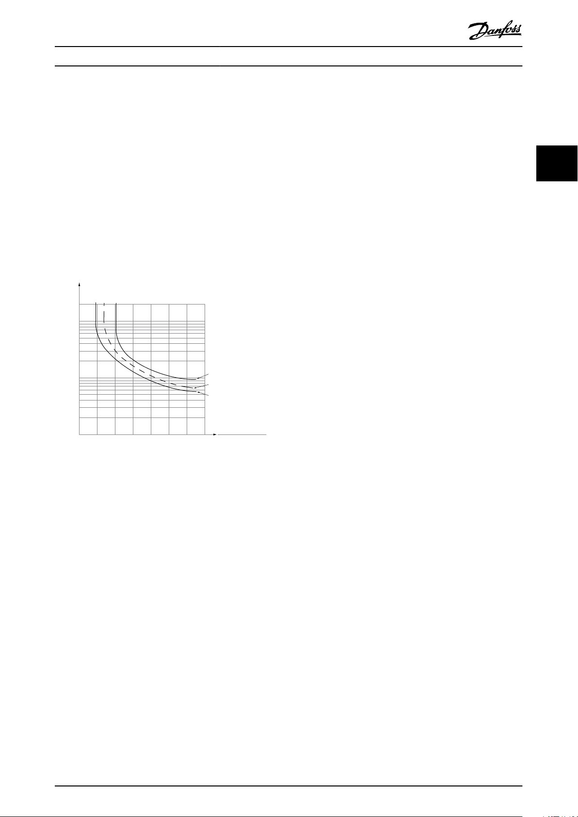
shown in Illustration 3.1.
Voltage limit
The inverter turns
link capacitors when a certain hard-coded voltage level is
reached.
Overtemperature
The drive has built-in temperature sensors and reacts
immediately to critical values via hard-coded limits.
o to protect the transistors and the DC
3.2.7 Locked Rotor Protection
There can be situations when the rotor is locked due to
excessive load or other factors. The locked rotor cannot
produce enough cooling, which in turn can overheat the
motor winding. The drive is able to detect the locked rotor
situation with PM VVC+ control (parameter 30-22 Locked
Rotor Protection).
3.2.8 Automatic Derating
The drive constantly checks for the following critical levels:
High temperature on the control card or heat
•
sink.
High motor load.
•
High DC-link voltage.
•
Low motor speed.
•
As a response to a critical level, the drive adjusts the
switching frequency. For high internal temperatures and
low motor speed, the drive can also force the PWM pattern
to SFAVM.
NOTICE
The automatic derating is dierent when
parameter 14-55 Output Filter is set to [2] Sine-Wave Filter
Fixed.
3.2.9 Automatic Energy Optimization
Automatic energy optimization (AEO) directs the drive to
monitor the load on the motor continuously and adjust
the output voltage to maximize eciency. Under light
load, the voltage is reduced and the motor current is
minimized. The motor benets from:
Increased eciency.
•
Reduced heating.
•
Quieter operation.
•
There is no need to select a V/Hz curve because the drive
automatically adjusts motor voltage.
3.2.10 Automatic Switching Frequency
Modulation
The drive generates short electrical pulses to form an AC
wave pattern. The switching frequency is the rate of these
pulses. A low switching frequency (slow pulsing rate)
causes audible noise in the motor, making a higher
switching frequency preferable. A high switching
frequency, however, generates heat in the drive that can
limit the amount of current available to the motor.
Automatic switching frequency modulation regulates these
conditions automatically to provide the highest switching
frequency without overheating the drive. By providing a
regulated high switching frequency, it quiets motor
operating noise at slow speeds, when audible noise control
is critical, and produces full output power to the motor
when required.
3.2.11 Automatic Derating for High
Switching Frequency
The drive is designed for continuous, full-load operation at
switching frequencies between 1.5–2 kHz for 380–480 V.
The frequency range depends on power size and voltage
rating. A switching frequency exceeding the maximum
allowed range generates increased heat in the drive and
requires the output current to be derated.
An automatic feature of the drive is load-dependent
switching frequency control. This feature allows the motor
to benet from as high a switching frequency as the load
allows.
3 3
MG06K102 Danfoss A/S © 03/2019 All rights reserved. 9
Page 12

Product Overview and Featur... VLT® AutomationDrive FC 361
3.2.12 Power Fluctuation Performance
The drive withstands mains uctuations such as:
Transients.
•
Momentary drop-outs.
•
33
The drive automatically compensates for input voltages
±10% from the nominal to provide full rated motor voltage
and torque. With auto restart selected, the drive automatically powers up after a voltage trip. With ying start, the
drive synchronizes to motor rotation before start.
Short voltage drops.
•
Surges.
•
3.2.13 Resonance Damping
Resonance damping eliminates the high-frequency motor
resonance noise. Automatic or manually selected frequency
damping is available.
3.2.14 Temperature-controlled Fans
Sensors in the drive regulate the operation of the internal
cooling fans. Often, the cooling fans do not run during low
load operation, or when in sleep mode or standby. These
sensors reduce noise, increase eciency, and extend the
operating life of the fan.
3.2.15 EMC Compliance
Electromagnetic interference (EMI) and radio frequency
interference (RFI) are disturbances that can aect an
electrical circuit due to electromagnetic induction or
radiation from an external source. The drive is designed to
comply with the EMC product standard for drives IEC
61800-3 and the European standard EN 55011. Motor
cables must be shielded and properly terminated to
comply with the emission levels in EN 55011. For more
information regarding EMC performance, see
chapter 7.13.1 EMC Test Results.
The components that make up the galvanic isolation
are:
Supply, including signal isolation.
•
Gatedrive for the IGBTs, trigger transformers, and
•
optocouplers.
The output current Hall eect transducers.
•
3.3 Custom Application Features
Custom application functions are the most common
features programmed in the drive for enhanced system
performance. They require minimum programming or setup. See the programming guide for instructions on
activating these functions.
3.3.1 Automatic Motor Adaptation
Automatic motor adaptation (AMA) is an automated test
procedure used to measure the electrical characteristics of
the motor. AMA provides an accurate electronic model of
the motor, allowing the drive to calculate optimal
performance and eciency. Running the AMA procedure
also maximizes the automatic energy optimization feature
of the drive. AMA is performed without the motor rotating
and without uncoupling the load from the motor.
3.3.2 Built-in PID Controller
The built-in proportional, integral, derivative (PID)
controller eliminates the need for auxiliary control devices.
The PID controller maintains constant control of closedloop systems where regulated pressure, ow, temperature,
or other system requirements must be maintained.
The drive can use 2 feedback signals from 2 dierent
devices, allowing the system to be regulated with dierent
feedback requirements. The drive makes control decisions
by comparing the 2 signals to optimize system
performance.
3.3.3 Motor Thermal Protection
3.2.16 Galvanic Isolation of Control
Terminals
All control terminals and output relay terminals are galvanically isolated from mains power, which completely
protects the controller circuitry from the input current. The
output relay terminals require their own grounding. This
isolation meets the stringent protective extra-low voltage
(PELV) requirements for isolation.
10 Danfoss A/S © 03/2019 All rights reserved. MG06K102
To protect the application from serious damage, the drive
oers several dedicated features.
Torque limit
The torque limit protects the motor from being overloaded
independent of the speed. Torque limit is controlled in
parameter 4-16 Torque Limit Motor Mode and
parameter 4-17 Torque Limit Generator Mode.
Parameter 14-25 Trip Delay at Torque Limit controls the time
before the torque limit warning trips.
Current limit
Parameter 4-18 Current Limit controls the current limit, and
parameter 14-24 Trip Delay at Current Limit controls the
time before the current limit warning trips.
Page 13
1.21.0 1.4
30
10
20
100
60
40
50
1.81.6 2.0
2000
500
200
400
300
1000
600
t [s]
175ZA052.12
f
OUT
= 2 x f
M,N
f
OUT
= 0.2 x f
M,N
f
OUT
= 1 x f
M,N
(par. 1-23)
IMN(par. 1-24)
I
M
Product Overview and Featur... Design Guide
Minimum speed limit
Parameter 4-12 Motor Speed Low Limit [Hz] sets the
minimum output speed that the drive can provide.
Maximum speed limit
Parameter 4-14 Motor Speed High Limit [Hz] or
parameter 4-19 Max Output Frequency sets the maximum
output speed that the drive can provide.
ETR (electronic thermal relay)
The drive ETR function measures the actual current, speed,
and time to calculate motor temperature. The function also
protects the motor from being overheated (warning or
trip). An external thermistor input is also available. ETR is
an electronic feature that simulates a bimetal relay based
on internal measurements. The characteristic is shown in
Illustration 3.1.
The drive can be congured (parameter 14-10 Mains Failure)
to dierent types of behavior during mains drop-out:
Trip lock once the DC-link is exhausted.
•
Coast with ying start whenever mains return
•
(parameter 1-73 Flying Start).
Kinetic back-up.
•
Controlled ramp down.
•
Flying start
This selection makes it possible to catch a motor that is
spinning freely due to a mains drop-out. This option is
relevant for centrifuges and fans.
Kinetic back-up
This selection ensures that the drive runs as long as there
is energy in the system. For short mains drop-out, the
operation is restored after mains return, without bringing
the application to a stop or losing control at any time.
Several variants of kinetic back-up can be selected.
Congure the behavior of the drive at mains drop-out in
parameter 14-10 Mains Failure and parameter 1-73 Flying
Start.
3.3.5 Automatic Restart
3 3
The drive can be programmed to restart the motor
automatically after a minor trip, such as momentary power
loss or uctuation. This feature eliminates the need for
manual resetting and enhances automated operation for
remotely controlled systems. The number of restart
Illustration 3.1 ETR
The X-axis shows the ratio between I
motor
and I
motor
attempts and the duration between attempts can be
limited.
3.3.6 Full Torque at Reduced Speed
nominal. The Y-axis shows the time in seconds before the
ETR cuts o and trips the drive. The curves show the
characteristic nominal speed at twice the nominal speed
and at 0.2 x the nominal speed.
At lower speed, the ETR cuts o at lower heat due to less
cooling of the motor. In that way, the motor is protected
from being overheated even at low speed. The ETR feature
calculates the motor temperature based on actual current
and speed. The calculated temperature is visible as a
The drive follows a variable V/Hz curve to provide full
motor torque even at reduced speeds. Full output torque
can coincide with the maximum designed operating speed
of the motor. This drive diers from variable torque drives
and constant torque drives. Variable torque drives provide
reduced motor torque at low speed. Constant torque
drives provide excess voltage, heat, and motor noise at less
than full speed.
readout parameter in parameter 16-18 Motor Thermal.
3.3.7 Frequency Bypass
3.3.4 Mains Drop-out
During a mains drop-out, the drive keeps running until the
DC-link voltage drops below the minimum stop level. The
minimum stop level is typically 15% below the lowest
rated supply voltage. The mains voltage before the dropout and the motor load determine how long it takes for
the drive to coast.
MG06K102 Danfoss A/S © 03/2019 All rights reserved. 11
In some applications, the system can have operational
speeds that create a mechanical resonance. This
mechanical resonance can generate excessive noise and
possibly damage mechanical components in the system.
The drive has 4 programmable bypass-frequency
bandwidths. The bandwidths allow the motor to step over
speeds that induce system resonance.
Page 14
. . .
. . .
Par. 13-11
Comparator Operator
Par. 13-43
Logic Rule Operator 2
Par. 13-51
SL Controller Event
Par. 13-52
SL Controller Action
130BB671.13
Coast
Start timer
Set Do X low
Select set-up 2
. . .
Running
Warning
Torque limit
Digital input X 30/2
. . .
=
TRUE longer than..
. . .
. . .
Product Overview and Featur... VLT® AutomationDrive FC 361
3.3.8 Motor Preheat
To preheat a motor in a cold or damp environment, a small
amount of DC current can be trickled continuously into the
motor to protect it from condensation and cold starts. This
function can eliminate the need for a space heater.
33
3.3.9 Programmable Set-ups
The drive has 4 set-ups that can be independently
programmed. Using multi-setup, it is possible to switch
between independently programmed functions activated
by digital inputs or a serial command. Independent set-ups
are used, for example, to change references, or for day/
night or summer/winter operation, or to control multiple
motors. The LCP shows the active set-up.
Set-up data can be copied from drive to drive by
downloading the information from the removable LCP.
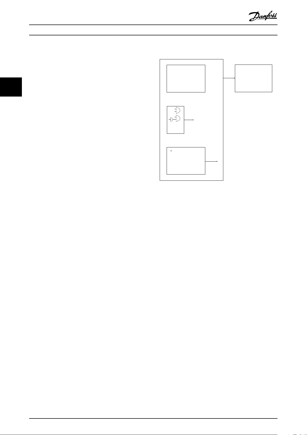
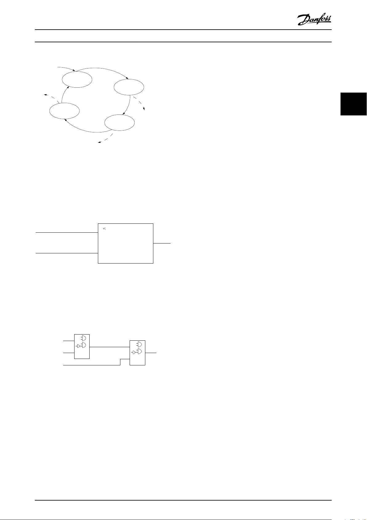
3.3.10 Smart Logic Control (SLC)
Smart logic control (SLC) is a sequence of user-dened
actions (see parameter 13-52 SL Controller Action [x])
executed by the SLC when the associated user-dened
event (see parameter 13-51 SL Controller Event [x]) is
evaluated as TRUE by the SLC.
The condition for an event can be a particular status, or
that the output from a logic rule or a comparator operand
becomes TRUE. The condition leads to an associated action
as shown in Illustration 3.2.
Illustration 3.2 SLC Event and Action
Events and actions are each numbered and linked in pairs
(states), which means that when event [0] is fullled
(attains the value TRUE), action [0] is executed. After the 1
action is executed, the conditions of the next event are
evaluated. If this event is evaluated as true, then the
corresponding action is executed. Only 1 event is
evaluated at any time. If an event is evaluated as false,
nothing happens in the SLC during the current scan
interval and no other events are evaluated. When the SLC
starts, it only evaluates event [0] during each scan interval.
Only when event [0] is evaluated as true, the SLC executes
action [0] and starts evaluating the next event. It is
possible to program 1–20 events and actions.
When the last event/action has been executed, the
sequence starts over again from event [0]/action [0].
Illustration 3.3 shows an example with 4 event/actions:
st
12 Danfoss A/S © 03/2019 All rights reserved. MG06K102
Page 15
130BA062.14
State 1
13-51.0
13-52.0
State 2
13-51.1
13-52.1
Start
event P13-01
State 3
13-51.2
13-52.2
State 4
13-51.3
13-52.3
Stop
event P13-02
Stop
event P13-02
Stop
event P13-02
Par. 13-11
Comparator Operator
=
TRUE longer than.
. . .
. . .
Par. 13-10
Comparator Operand
Par. 13-12
Comparator Value
130BB672.10
. . .
. . .
. . .
. . .
Par. 13-43
Logic Rule Operator 2
Par. 13-41
Logic Rule Operator 1
Par. 13-40
Logic Rule Boolean 1
Par. 13-42
Logic Rule Boolean 2
Par. 13-44
Logic Rule Boolean 3
130BB673.10
Product Overview and Featur... Design Guide
Illustration 3.3 Order of Execution when 4 Events/Actions are
Programmed
Comparators
Comparators are used for comparing continuous variables
(output frequency, output current, analog input, and so on)
to xed preset values.
3.4 Dynamic Braking Overview
Dynamic braking slows the motor using 1 of the following
methods:
AC brake
•
The brake energy is distributed in the motor by
changing the loss conditions in the motor
(parameter 2-10 Brake Function = [2]). The AC
brake function cannot be used in applications
with high cycling frequency since this situation
overheats the motor.
DC brake
•
An overmodulated DC current added to the AC
current works as an eddy current brake
(parameter 2-02 DC Braking Time ≠ 0 s).
3 3
Illustration 3.4 Comparators
Logic rules
Combine up to 3 boolean inputs (TRUE/FALSE inputs) from
timers, comparators, digital inputs, status bits, and events
using the logical operators AND, OR, and NOT.
Illustration 3.5 Logic Rules
MG06K102 Danfoss A/S © 03/2019 All rights reserved. 13
Page 16
130BG823.10
225 mm (8.9 in)
225 mm (8.9 in)
Product Overview and Featur... VLT® AutomationDrive FC 361
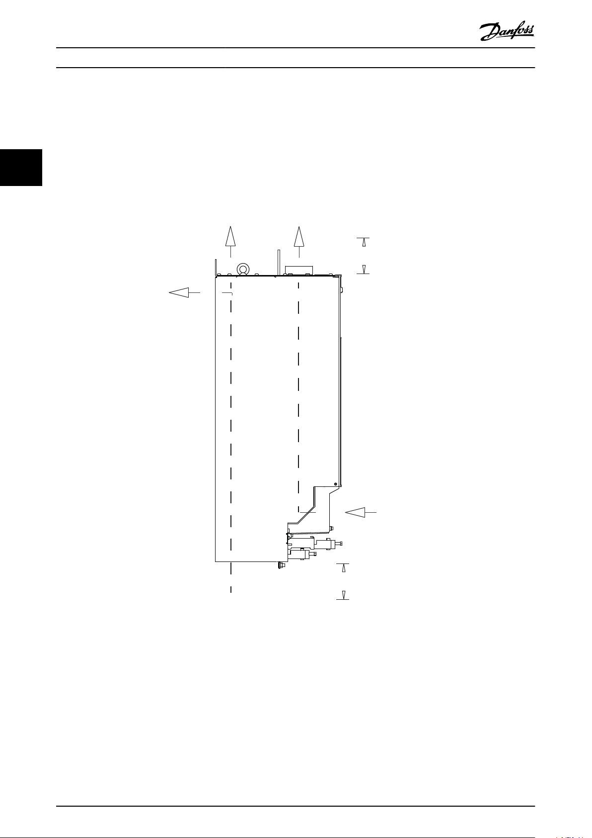
3.5 Back-channel Cooling Overview
A unique back-channel duct passes cooling air over the heat sinks with minimal air passing through the electronics area.
There is an IP54/Type 12 seal between the back-channel cooling duct and the electronics area of the VLT® drive. This backchannel cooling allows 90% of the heat losses to be exhausted directly outside the enclosure. This design improves
reliability and prolongs component life by dramatically reducing interior temperatures and contamination of the electronic
33
components. Dierent back-channel cooling kits are available to redirect the airow based on individual needs.
3.5.1 Airow for J8 & J9 Enclosures
Illustration 3.6 Standard Airow Conguration for Enclosures J8 and J9
14 Danfoss A/S © 03/2019 All rights reserved. MG06K102
Page 17

Options and Accessories Ove... Design Guide
4 Options and Accessories Overview
4.1 Fieldbus Devices
This section describes the eldbus devices that are
available with the VLT® AutomationDrive FC 361 series.
Using a eldbus device reduces system cost, delivers faster
and more ecient communication, and provides an easier
user interface. For ordering numbers, refer to
chapter 10.2 Ordering Numbers for Options and Accessories.
4.1.1
VLT® PROFIBUS DP-V1 MCA 101
The VLT® PROFIBUS DP-V1 MCA 101 provides:
Wide compatibility, a high level of availability,
•
support for all major PLC vendors, and compatibility with future versions.
Fast, ecient communication, transparent instal-
•
lation, advanced diagnosis, and parameterization
and auto-conguration of process data via a GSD
le.
Acyclic parameterization using PROFIBUS DP-V1,
•
PROFIdrive, or Danfoss FC prole state machines.
4.1.2
VLT® PROFINET MCA 120
The VLT® PROFINET MCA 120 combines the highest
performance with the highest degree of openness. The
option is designed so that many of the features from the
VLT® PROFIBUS MCA 101 can be reused, minimizing user
eort to migrate PROFINET and securing the investment in
a PLC program.
Same PPO types as the VLT® PROFIBUS DP V1
•
MCA 101 for easy migration to PROFINET.
Built-in web server for remote diagnosis and
•
reading out of basic drive parameters.
Supports MRP.
•
Supports DP-V1. Diagnostic allows easy, fast, and
•
standardized handling of warning and fault
information into the PLC, improving bandwidth in
the system.
Implementation in accordance with Conformance
•
Class B.
Functional Extensions
4.2
This section describes the functional extension options that
are available with the VLT® AutomationDrive FC 361 series.
For ordering numbers, refer to chapter 10.2 Ordering
Numbers for Options and Accessories.
4.2.1
VLT® General Purpose I/O Module
MCB 101
The VLT® General Purpose I/O Module MCB 101 oers an
extended number of control inputs and outputs:
3 digital inputs 0–24 V: Logic 0 < 5 V; Logic 1 >
•
10 V.
2 analog inputs 0–10 V: Resolution 10 bits plus
•
sign.
2 digital outputs NPN/PNP push-pull.
•
1 analog output 0/4–20 mA.
•
Spring-loaded connection.
•
4.2.2
VLT® Encoder Input MCB 102
The MCB 102 option oers the possibility to connect
various types of incremental and absolute encoders. The
connected encoder can be used for closed-loop speed
control and closed-loop ux motor control.
The following encoder types are supported:
5 V TTL (RS 422).
•
1VPP SinCos.
•
4.2.3
VLT® Resolver Option MCB 103
The MCB 103 option enables connection of a resolver to
provide speed feedback from the motor.
Primary voltage: 2–8 V
•
Primary frequency: 2.0–15 kHz.
•
Primary maximum current: 50 mA rms.
•
Secondary input voltage: 4 V
•
Spring-loaded connection.
•
rms
.
.
rms
4 4
MG06K102 Danfoss A/S © 03/2019 All rights reserved. 15
Page 18
Specications VLT® AutomationDrive FC 361
5 Specications
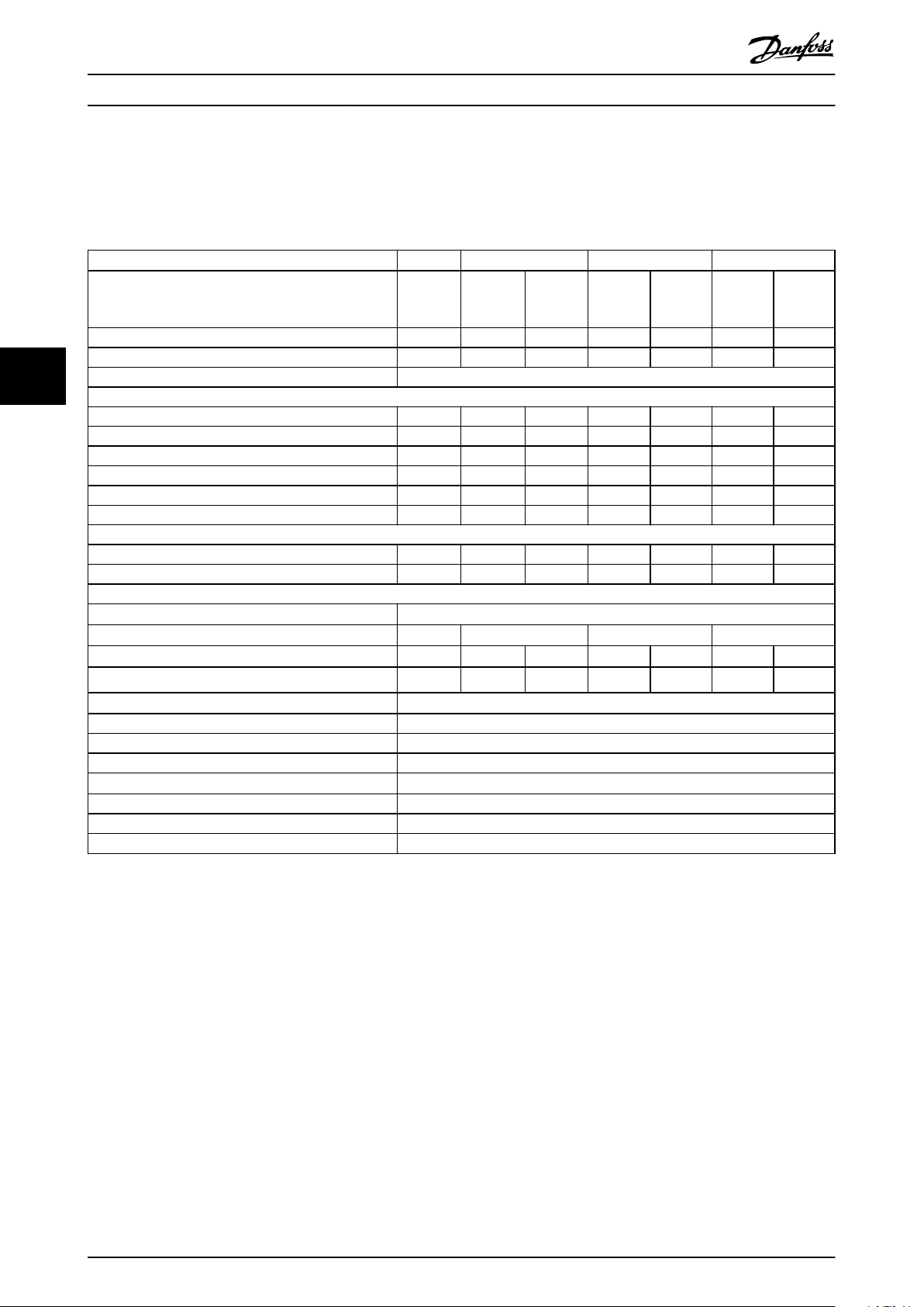
5.1 Electrical Data, 380-480 V
VLT® AutomationDrive FC 361
High/normal overload NO HO NO HO NO HO NO
(High overload=150% current during 60 s, normal
overload=110% current during 60 s)
Typical shaft output at 400 V [kW] 90 90 110 110 132 132 160
Typical shaft output at 460 V [hp] 125 125 150 150 200 200 250
55
Enclosure size J8
Output current (3-phase)
Continuous (at 400 V) [A] 177 177 212 212 260 260 315
Intermittent (60 s overload) (at 400 V) [A] 195 266 233 318 286 390 347
Continuous (at 460 V) [A] 160 160 190 190 240 240 302
Intermittent (60 s overload) (at 460 V) [kVA] 176 240 209 285 264 360 332
Continuous kVA (at 400 V) [kVA] 123 123 147 147 180 180 218
Continuous kVA (at 460 V) [kVA] 127 127 151 151 191 191 241
Maximum input current
Continuous (at 400 V) [A] 171 171 204 204 251 251 304
Continuous (at 460 V) [A] 154 154 183 183 231 231 291
Maximum number and size of cables per phase
Mains and motor [mm2 (AWG)]
Maximum external mains fuses [A]
Estimated power loss at 400 V [W]
Estimated power loss at 460 V [W]
Eciency
Output frequency [Hz] 0–590
Heat sink overtemperature trip [°C (°F)]
Weight, enclosure protection rating IP20 kg (lbs) 98 (216)
Eciency
Output frequency [Hz] 0–590
Heat sink overtemperature trip [°C (°F)]
Control card overtemperature trip [°C (°F)]
3)
3)
1)
2), 3)
2), 3)
N90K N110 N132 N160
2x95 (2x3/0)
315 315 350 400
2031 2031 2559 2289 2954 2923 3770
1828 1828 2261 2051 2724 2089 3628
0.98
110 (230)
0.98
110 (230)
75 (167)
Table 5.1 Electrical Data for Enclosures J8, Mains Supply 3x380–480 V AC
1) For fuse ratings, see chapter 7.5 Fuses and Circuit Breakers.
2) Typical power loss is at normal conditions and expected to be within ±15% (tolerance relates to variety in voltage and cable conditions). These
values are based on a typical motor eciency (IE/IE3 border line). Lower eciency motors add to the power loss in the drive. Applies to
dimensioning of drive cooling. If the switching frequency is higher than the default setting, the power losses can increase. LCP and typical control
card power consumptions are included. For power loss data according to EN 50598-2, refer to drives.danfoss.com/knowledge-center/energy-
eciency-directive/#/. Options and customer load can add up to 30 W to the losses, though usually a fully loaded control card and options for
slots A and B each add only 4 W.
3) Measured using 5 m (16.4 ft) shielded motor cables at rated load and rated frequency. Eciency measured at nominal current. For energy
eciency class, see chapter 5.4 Ambient Conditions. For part load losses, see drives.danfoss.com/knowledge-center/energy-eciency-directive/#/.
16 Danfoss A/S © 03/2019 All rights reserved. MG06K102
Page 19
Specications Design Guide
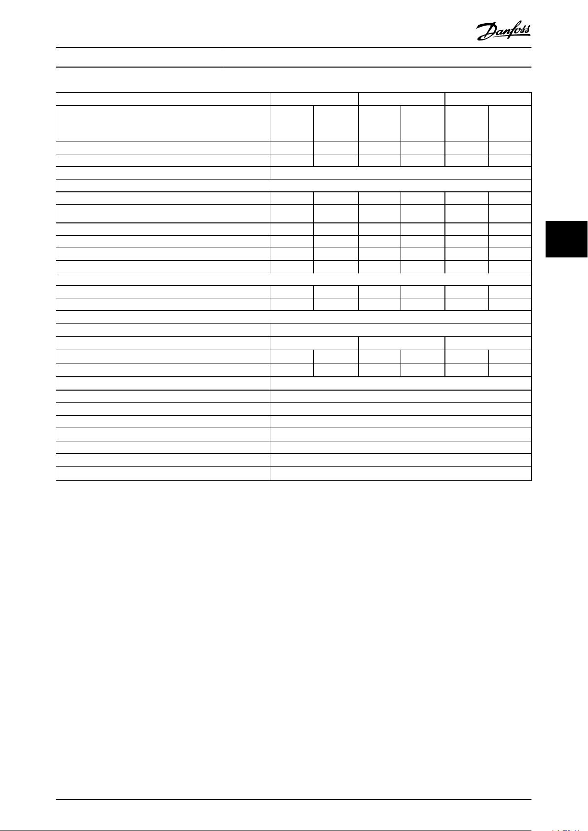
VLT® AutomationDrive FC 361
High/normal overload HO NO HO NO HO NO
(High overload=150% current during 60 s, normal
overload=110% current during 60 s)
Typical shaft output at 400 V [kW] 160 200 200 250 250 315
Typical shaft output at 460 V [hp] 250 300 300 350 350 450
Enclosure size J9
Output current (3-phase)
Continuous (at 400 V) [A] 315 395 395 480 480 588
Intermittent (60 s overload) (at 400 V) [A]
Continuous (at 460 V) [A] 302 361 361 443 443 535
Intermittent (60 s overload) (at 460 V) [kVA] 453 397 542 487 665 589
Continuous kVA (at 400 V) [kVA] 218 274 274 333 333 407
Continuous kVA (at 460 V) [kVA] 241 288 288 353 353 426
Maximum input current
Continuous (at 400 V) [A] 304 381 381 463 463 567
Continuous (at 460 V) [A] 291 348 348 427 427 516
Maximum number and size of cables per phase
Mains and motor [mm2 (AWG)]
Maximum external mains fuses [A]
Estimated power loss at 400 V [W]
Estimated power loss at 460 V [W]
Eciency
Output frequency [Hz] 0–590
Heat sink overtemperature trip [°C (°F)]
Weight, enclosure protection rating IP20 kg (lbs) 164 (362)
Eciency
Output frequency [Hz] 0–590
Heat sink overtemperature trip [°C (°F)]
Control card overtemperature trip [°C (°F)]
3)
3)
1)
2), 3)
2), 3)
N200 N250 N315
473 435 593 528 720 647
2x185 (2x350 mcm)
550 630 800
3093 4116 4039 5137 5004 6674
2872 3569 3575 4566 4458 5714
0.98
110 (230)
0.98
110 (230)
80 (176)
5 5
Table 5.2 Electrical Data for Enclosures J9, Mains Supply 3x380–480 V AC
1) For fuse ratings, see chapter 7.5 Fuses and Circuit Breakers.
±
2) Typical power loss is at normal conditions and expected to be within
values are based on a typical motor eciency (IE/IE3 border line). Lower eciency motors add to the power loss in the drive. Applies to
dimensioning of drive cooling. If the switching frequency is higher than the default setting, the power losses can increase. LCP and typical control
card power consumptions are included. For power loss data according to EN 50598-2, refer to drives.danfoss.com/knowledge-center/energy-
eciency-directive/#/. Options and customer load can add up to 30 W to the losses, though usually a fully loaded control card and options for
slots A and B each add only 4 W.
3) Measured using 5 m (16.4 ft) shielded motor cables at rated load and rated frequency. Eciency measured at nominal current. For energy
eciency class, see chapter 5.4 Ambient Conditions. For part load losses, see drives.danfoss.com/knowledge-center/energy-eciency-directive/#/.
15% (tolerance relates to variety in voltage and cable conditions). These
MG06K102 Danfoss A/S © 03/2019 All rights reserved. 17
Page 20

Specications VLT® AutomationDrive FC 361
5.2 Mains Supply
Mains supply (L1, L2, L3)
Supply voltage 380–480 V ±10%
Mains voltage low/mains voltage drop-out:
During low mains voltage or a mains drop-out, the drive continues until the DC-link voltage drops below the minimum stop
level, which corresponds typically to 15% below the lowest rated supply voltage of the drive. Power-up and full torque cannot be
expected at mains voltage lower than 10% below the lowest rated supply voltage of the drive.
Supply frequency 50/60 Hz ±5%
Maximum imbalance temporary between mains phases 3.0% of rated supply voltage
True power factor (λ) ≥0.9 nominal at rated load
55
Displacement power factor (cos Φ) near unity (>0.98)
Switching on input supply L1, L2, L3 (power-ups) Maximum 1 time/2 minute
Environment according to EN60664-1 Overvoltage category III/pollution degree 2
The drive is suitable for use on a circuit capable of delivering up to 100 kA short circuit current rating (SCCR) at 480/600 V.
1) Calculations based on IEC61800-3.
1)
5.3 Motor Output and Motor Data
Motor output (U, V, W)
Output voltage 0–100% of supply voltage
Output frequency 0–590 Hz
Output frequency in ux mode 0–300 Hz
Switching on output Unlimited
Ramp times 0.01–3600 s
1) Dependent on voltage and power.
1)
Torque characteristics
Starting torque (constant torque) Maximum 150% for 60 s
Overload torque (constant torque) Maximum 150% for 60 s
1) Percentage relates to the nominal current of the drive.
2) Once every 10 minutes.
1), 2)
1), 2)
5.4 Ambient Conditions
Environment
J8/J9 enclosure IP20/Chassis
Vibration test (standard/ruggedized) 0.7 g/1.0 g
Relative humidity 5%–95% (IEC 721-3-3; Class 3K3 (non-condensing) during operation)
Aggressive environment (IEC 60068-2-43) H2S test Class Kd
Aggressive gases (IEC 60721-3-3) Class 3C3
Test method according to IEC 60068-2-43 H2S (10 days)
Ambient temperature (at SFAVM switching mode)
- with derating Maximum 55 °C (131 °F)
- with full output power of typical EFF2 motors (up to 90% output current) Maximum 50 °C (122 °F)
- at full continuous FC output current Maximum 45 °C (113 °F)
Minimum ambient temperature during full-scale operation 0 °C (32 °F)
Minimum ambient temperature at reduced performance -10 °C (14 °F)
Temperature during storage/transport -25 to +65/70 °C (13 to 149/158 °F)
Maximum altitude above sea level without derating 1000 m (3281 ft)
Maximum altitude above sea level with derating 3000 m (9842 ft)
1) For more information on derating, see chapter 6.6 Derating.
EMC standards, Emission EN 61800-3
1)
1)
1)
18 Danfoss A/S © 03/2019 All rights reserved. MG06K102
Page 21

Specications Design Guide
EMC standards, Immunity EN 61800-3
Energy eciency class
1) Determined according to EN 50598-2 at:
Rated load.
•
90% rated frequency.
•
Switching frequency factory setting.
•
Switching pattern factory setting.
•
1)
IE2
5.5 Cable Specications
Cable lengths and cross-sections for control cables
Maximum motor cable length, shielded 150 m (492 ft)
Maximum motor cable length, unshielded 300 m (984 ft)
Maximum cross-section to motor and mains See chapter 5.1 Electrical Data, 380-480 V
Maximum cross-section to control terminals, rigid wire 1.5 mm2/16 AWG (2x0.75 mm2)
Maximum cross-section to control terminals, exible cable 1 mm2/18 AWG
Maximum cross-section to control terminals, cable with enclosed core 0.5 mm2/20 AWG
Minimum cross-section to control terminals 0.25 mm2/23 AWG
1) For power cables, see electrical data in chapter 5.1 Electrical Data, 380-480 V.
5.6 Control Input/Output and Control Data
Digital inputs
Programmable digital inputs 4 (6)
Terminal number 18, 19, 271), 291), 32, 33
Logic PNP or NPN
Voltage level 0–24 V DC
Voltage level, logic 0 PNP <5 V DC
Voltage level, logic 1 PNP >10 V DC
Voltage level, logic 0 NPN >19 V DC
Voltage level, logic 1 NPN <14 V DC
Maximum voltage on input 28 V DC
Input resistance, R
All digital inputs are galvanically isolated from the supply voltage (PELV) and other high-voltage terminals.
1) Terminals 27 and 29 can also be programmed as outputs.
i
Approximately 4 kΩ
5 5
1)
Analog inputs
Number of analog inputs 2
Terminal number 53, 54
Modes Voltage or current
Mode select Switches A53 and A54
Voltage mode Switch A53/A54=(U)
Voltage level 0 V to +10 V (scaleable)
Input resistance, R
Maximum voltage ±20 V
Current mode Switch A53/A54=(I)
Current level 0/4 to 20 mA (scaleable)
Input resistance, R
Maximum current 30 mA
Resolution for analog inputs 10 bit (+ sign)
Accuracy of analog inputs Maximum error 0.5% of full scale
Bandwidth 100 Hz
The analog inputs are galvanically isolated from the supply voltage (PELV) and other high-voltage terminals.
MG06K102 Danfoss A/S © 03/2019 All rights reserved. 19
i
i
Approximately 10 kΩ
Approximately 200 Ω
Page 22

Mains
Functional
isolation
PELV isolation
Motor
DC-bus
High
voltage
Control
+24 V
RS485
18
37
130BA117.10
Specications VLT® AutomationDrive FC 361
Illustration 5.1 PELV Isolation
55
Pulse inputs
Programmable pulse inputs 2
Terminal number pulse 29, 33
Maximum frequency at terminal 29, 33 (push-pull driven) 110 kHz
Maximum frequency at terminal 29, 33 (open collector) 5 kHz
Minimum frequency at terminal 29, 33 4 Hz
Voltage level See Digital Inputs in chapter 5.6 Control Input/Output and Control Data
Maximum voltage on input 28 V DC
Input resistance, R
i
Pulse input accuracy (0.1–1 kHz) Maximum error: 0.1% of full scale
Analog output
Number of programmable analog outputs 1
Terminal number 42
Current range at analog output 0/4–20 mA
Maximum resistor load to common at analog output 500 Ω
Accuracy on analog output Maximum error: 0.8% of full scale
Resolution on analog output 8 bit
The analog output is galvanically isolated from the supply voltage (PELV) and other high-voltage terminals.
Control card, RS485 serial communication
Terminal number 68 (P, TX+, RX+), 69 (N, TX-, RX-)
Terminal number 61 Common for terminals 68 and 69
The RS485 serial communication circuit is functionally separated from other central circuits and galvanically isolated from the
supply voltage (PELV).
Approximately 4 kΩ
Digital output
Programmable digital/pulse outputs 2
Terminal number 27, 29
Voltage level at digital/frequency output 0–24 V
Maximum output current (sink or source) 40 mA
Maximum load at frequency output 1 kΩ
Maximum capacitive load at frequency output 10 nF
Minimum output frequency at frequency output 0 Hz
Maximum output frequency at frequency output 32 kHz
Accuracy of frequency output Maximum error: 0.1% of full scale
Resolution of frequency outputs 12 bit
1) Terminals 27 and 29 can also be programmed as inputs.
The digital output is galvanically isolated from the supply voltage (PELV) and other high-voltage terminals.
20 Danfoss A/S © 03/2019 All rights reserved. MG06K102
1)
Page 23

Specications Design Guide
Control card, 24 V DC output
Terminal number 12, 13
Maximum load 200 mA
The 24 V DC supply is galvanically isolated from the supply voltage (PELV), but has the same potential as the analog and digital
inputs and outputs.
Relay outputs
Programmable relay outputs 2
Maximum cross-section to relay terminals 2.5 mm2 (12 AWG)
Minimum cross-section to relay terminals 0.2 mm2 (30 AWG)
Length of stripped wire 8 mm (0.3 in)
Relay 01 terminal number 1–3 (break), 1–2 (make)
Maximum terminal load (AC-1)1) on 1–2 (NO) (Resistive load)
Maximum terminal load (AC-15)1) on 1–2 (NO) (Inductive load @ cosφ 0.4) 240 V AC, 0.2 A
Maximum terminal load (DC-1)1) on 1–2 (NO) (Resistive load) 80 V DC, 2 A
Maximum terminal load (DC-13)1) on 1–2 (NO) (Inductive load) 24 V DC, 0.1 A
Maximum terminal load (AC-1)1) on 1–3 (NC) (Resistive load) 240 V AC, 2 A
Maximum terminal load (AC-15)1) on 1–3 (NC) (Inductive load @ cosφ 0.4) 240 V AC, 0.2 A
Maximum terminal load (DC-1)1) on 1–3 (NC) (Resistive load) 50 V DC, 2 A
Maximum terminal load (DC-13)1) on 1–3 (NC) (Inductive load) 24 V DC, 0.1 A
Minimum terminal load on 1–3 (NC), 1–2 (NO) 24 V DC 10 mA, 24 V AC 2 mA
Environment according to EN 60664-1 Overvoltage category III/pollution degree 2
Relay 02 terminal number 4–6 (break), 4–5 (make)
Maximum terminal load (AC-1)1) on 4–5 (NO) (Resistive load)
Maximum terminal load (AC-15)1) on 4–5 (NO) (Inductive load @ cosφ 0.4) 240 V AC, 0.2 A
Maximum terminal load (DC-1)1) on 4–5 (NO) (Resistive load) 80 V DC, 2 A
Maximum terminal load (DC-13)1) on 4–5 (NO) (Inductive load) 24 V DC, 0.1 A
Maximum terminal load (AC-1)1) on 4–6 (NC) (Resistive load) 240 V AC, 2 A
Maximum terminal load (AC-15)1) on 4–6 (NC) (Inductive load @ cosφ 0.4) 240 V AC, 0.2 A
Maximum terminal load (DC-1)1) on 4–6 (NC) (Resistive load) 50 V DC, 2 A
Maximum terminal load (DC-13)1) on 4–6 (NC) (Inductive load) 24 V DC, 0.1 A
Minimum terminal load on 4–6 (NC), 4–5 (NO) 24 V DC 10 mA, 24 V AC 2 mA
Environment according to EN 60664-1 Overvoltage category III/pollution degree 2
The relay contacts are galvanically isolated from the rest of the circuit by reinforced isolation (PELV).
1) IEC 60947 part 4 and 5.
2) Overvoltage Category II.
2), 3)
2), 3)
400 V AC, 2 A
400 V AC, 2 A
5 5
Control card, +10 V DC output
Terminal number 50
Output voltage 10.5 V ±0.5 V
Maximum load 25 mA
The 10 V DC supply is galvanically isolated from the supply voltage (PELV) and other high-voltage terminals.
Control characteristics
Resolution of output frequency at 0–1000 Hz ±0.003 Hz
System response time (terminals 18, 19, 27, 29, 32, 33) ≤2 m/s
Speed control range (open loop) 1:100 of synchronous speed
Speed accuracy (open loop) 30–4000 RPM: Maximum error of ±8 RPM
All control characteristics are based on a 4-pole asynchronous motor.
Control card performance
Scan interval 5 M/S
MG06K102 Danfoss A/S © 03/2019 All rights reserved. 21
Page 24

Specications VLT® AutomationDrive FC 361
Control card, USB serial communication
USB standard 1.1 (full speed)
USB plug USB type B device plug
NOTICE
Connection to PC is carried out via a standard host/device USB cable.
The USB connection is galvanically isolated from the supply voltage (PELV) and other high-voltage terminals.
The USB connection is not galvanically isolated from ground. Use only isolated laptop/PC as connection to the USB
connector on the drive or an isolated USB cable/converter.
5.7 Enclosure Weights
55
Enclosure 380–480 V
J8 98 (216)
J9 164 (362)
Table 5.3 Enclosure J8–J9 Weights, kg (lb)
22 Danfoss A/S © 03/2019 All rights reserved. MG06K102
Page 25
130BF322.10
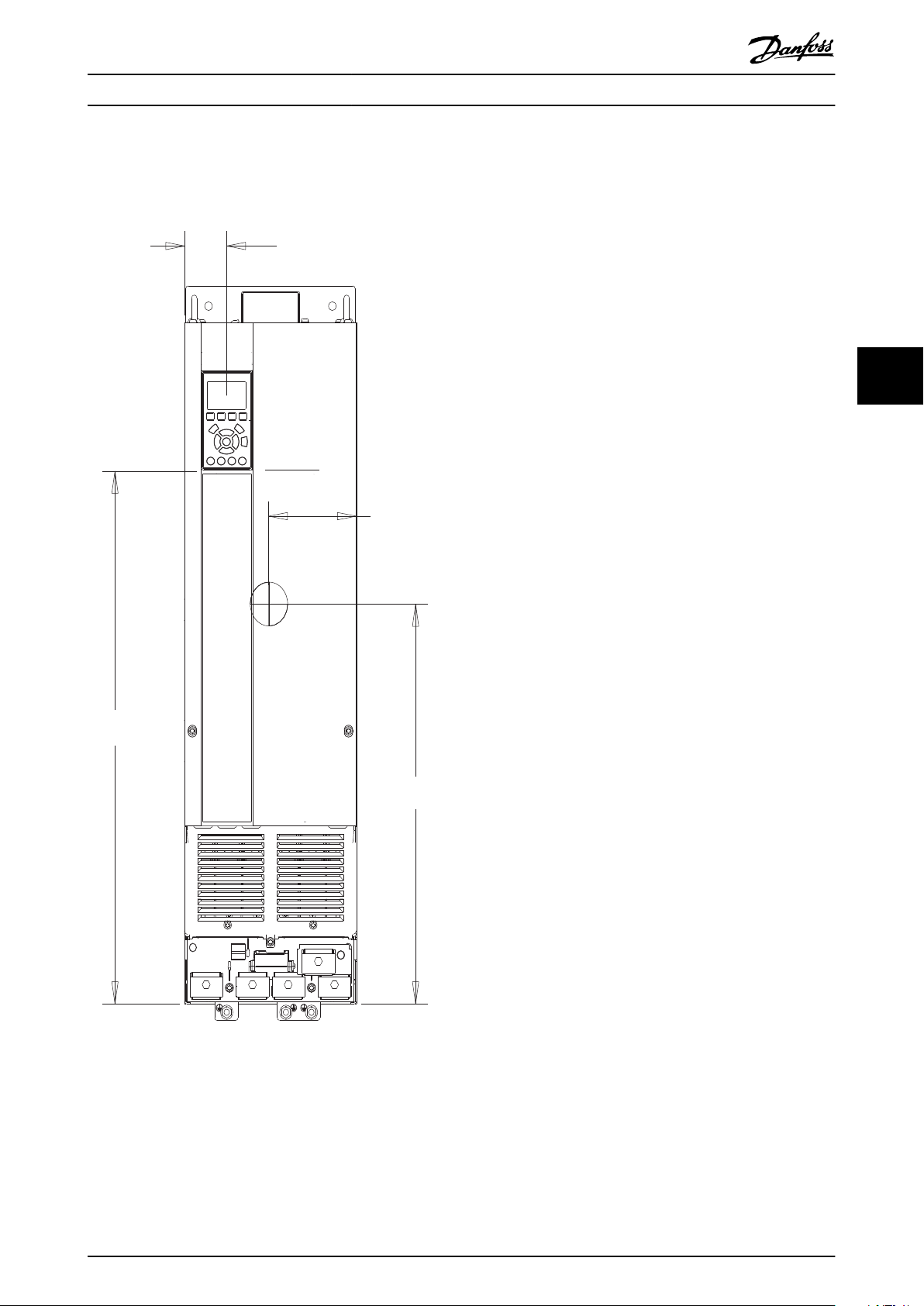
61 (2.4)
128 (5.0)
495 (19.5)
660 (26.0)
Specications Design Guide
5.8 Exterior and Terminal Dimensions
5.8.1 J8 Exterior Dimensions
5 5
Illustration 5.2 Front View of J8
MG06K102 Danfoss A/S © 03/2019 All rights reserved. 23
Page 26
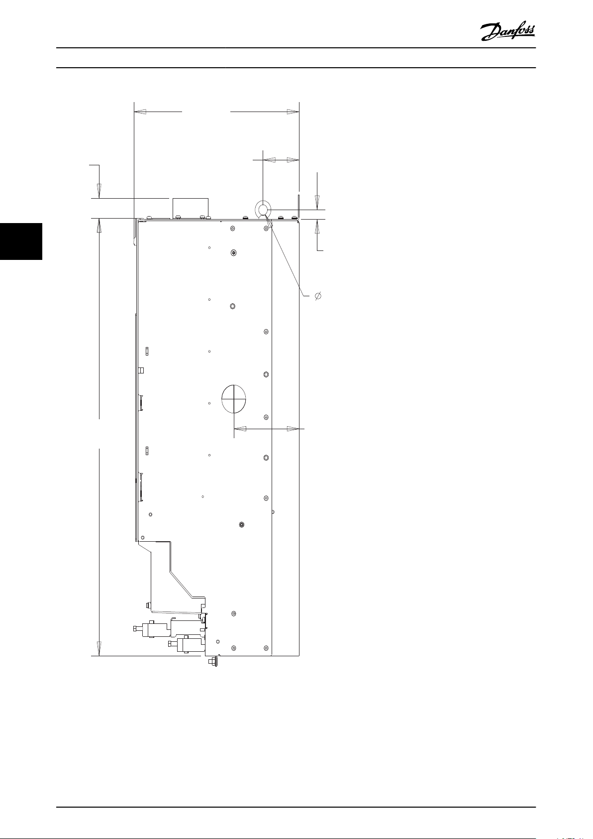
148 (5.8)
20 (0.8)
130BF801.10
844 (33.2)
39 (1.5)
375 (14.8)
82 (3.2)
18 (0.7)
Specications VLT® AutomationDrive FC 361
55
Illustration 5.3 Side View of J8
24 Danfoss A/S © 03/2019 All rights reserved. MG06K102
Page 27
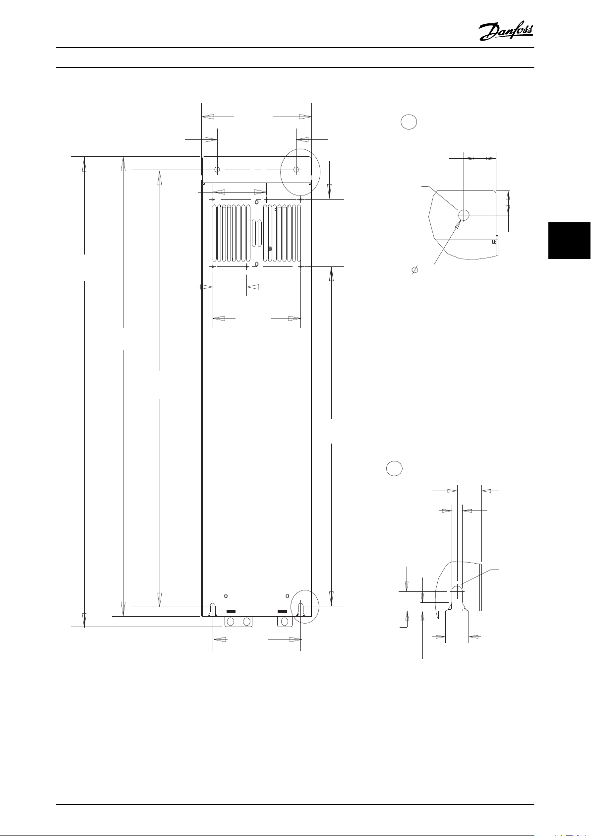
656 (25.8)
200 (7.9)
200 (7.9)
130 (5.1)
889 (35.0)
909 (35.8)
844 (33.2)
78 (3.1)
123
(4.8)
250 (9.8)
180 (7.1)
A
B
A
B
33 (1.3)
11 (0.4)
25 (1.0)
11 (0.4)
20 (0.8)
9 (0.3)
24
(0.9)
25 (1.0)
M10
M10
130BF802.10
Specications Design Guide
5 5
Illustration 5.4 Back View of J8
MG06K102 Danfoss A/S © 03/2019 All rights reserved. 25
Page 28
e30bg615.10
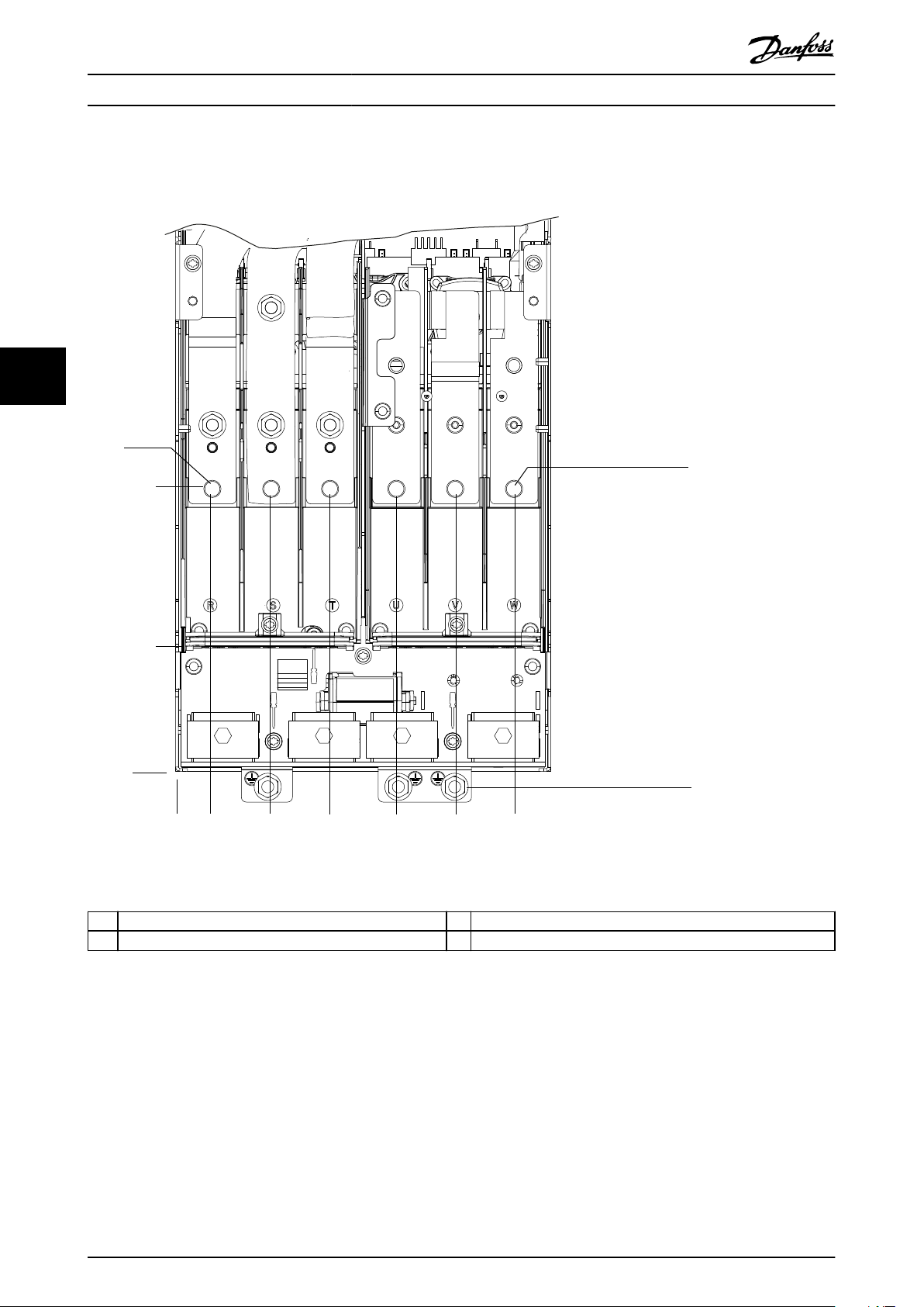
83 (3.3)
0.0
188 (7.4)
22 (0.9)
62 (2.4)
101 (4.0)
145 (5.7)
184 (7.2)
223 (8.8)
0.0
1
2
3
Specications VLT® AutomationDrive FC 361
5.8.2 J8 Terminal Dimensions
55
1 Mains terminals 3 Ground terminals
2 Motor terminals – –
Illustration 5.5 J8 Terminal Dimensions (Front View)
26 Danfoss A/S © 03/2019 All rights reserved. MG06K102
Page 29
M10
13 (0.5)
32 (1.3)
59 (2.3)
10 (0.4)
244 (9.6)
272 (10.7)
0.0
0.0
1
2
4
3
5
M10
13 (0.5)
32 (1.3)
145 (5.7)
182 (7.2)
3X M8x18
0
0
e30bg573.10
Specications Design Guide
5 5
1 and 4 Mains terminals 2 and 5 Motor terminals
3 Ground terminals – –
Illustration 5.6 J8 Terminal Dimensions (Side Views)
MG06K102 Danfoss A/S © 03/2019 All rights reserved. 27
Page 30
130BF323.10
176 (6.9)
611 (24.1)
59 (2.3)
868 (34.2)
55
Specications VLT® AutomationDrive FC 361
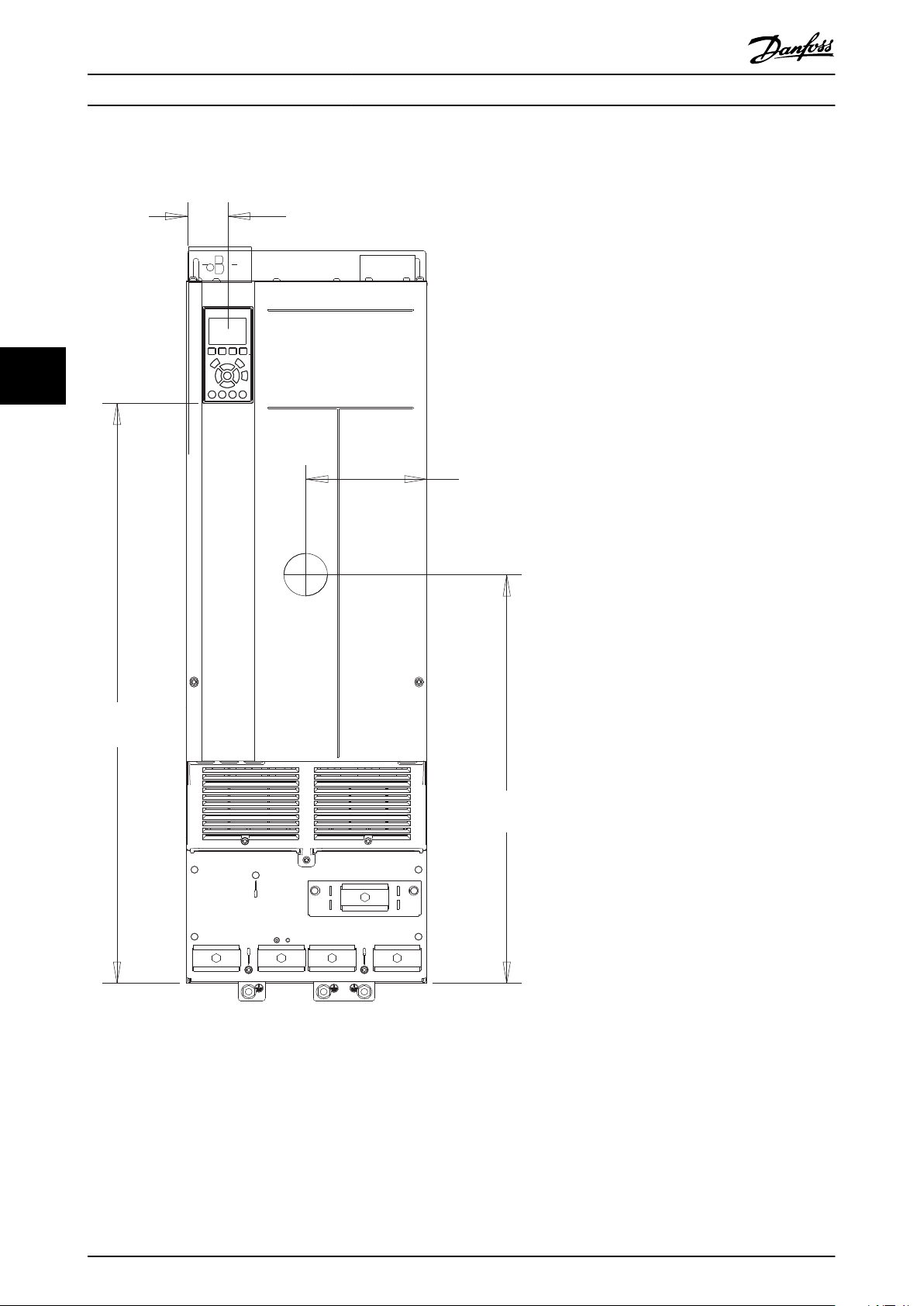
5.8.3 J9 Exterior Dimensions
Illustration 5.7 Front View of J9
28 Danfoss A/S © 03/2019 All rights reserved. MG06K102
Page 31

130BF803.10
20 (0.8)
148 (5.8)
18 (0.7)
1050 (41.3)
39 (1.5)
375 (14.8)
142 (5.6)
Specications Design Guide
5 5
Illustration 5.8 Side View of J9
MG06K102 Danfoss A/S © 03/2019 All rights reserved. 29
Page 32

B
130BF804.10
B
857 (33.7)
A
A
320 (12.6)
280 (11.0)
350 (13.8)
107
(4.2)
213 (8.4)
1122 (44.2)
1096 (43.1)
1051 (41.4)
271 (10.7)
130 (5.1)
25 (1.0)
33 (1.3)
11 (0.4)
40
(1.6)
11 (0.4)
9 (0.3)
20 (0.8)
24 (0.9)
Specications VLT® AutomationDrive FC 361
55
Illustration 5.9 Back View of J9
30 Danfoss A/S © 03/2019 All rights reserved. MG06K102
Page 33

33 (1.3)
91 (3.6)
149 (5.8)
211 (8.3)
265 (10.4)
319 (12.6)
200 (7.9)
319 (12.6)
e30bg616.10
0.0
o.o
1
2
3
Specications Design Guide
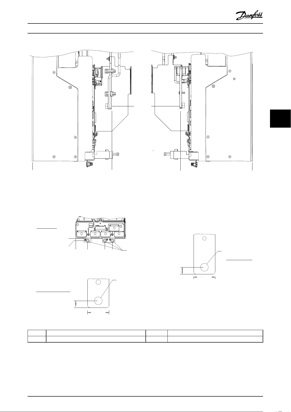
5.8.4 J9 Terminal Dimensions
5 5
1 Mains terminals 3 Ground terminals
2 Motor terminals – –
Illustration 5.10 J9 Terminal Dimensions (Front View)
MG06K102 Danfoss A/S © 03/2019 All rights reserved. 31
Page 34

4
3
91 (3.6)
13 (0.5)
200 (7.9)
259 (10.2)
3X M10X20
0
0
M10
19 (0.8)
38 (1.5)
255 (10.0)
284 (11.2)
0.0
0.0
1
2
5
M10
22 (0.9)
35 (1.4)
15 (0.6)
18 (0.7)
e30bg574.10
Specications VLT® AutomationDrive FC 361
55
1 and 4 Mains terminals 2 and 5 Motor terminals
3 Ground terminals – –
Illustration 5.11 J9 Terminal Dimensions (Side Views)
32 Danfoss A/S © 03/2019 All rights reserved. MG06K102
Page 35

e30bg512.11
65° min
Mechanical Installation Con... Design Guide
6 Mechanical Installation Considerations
6.1 Storage
Store the drive in a dry location. Keep the equipment
sealed in its packaging until installation. Refer to
chapter 5.4 Ambient Conditions for recommended ambient
temperature.
Periodic forming (capacitor charging) is not necessary
during storage unless storage exceeds 12 months.
6.2 Lifting the Unit
Always lift the drive using the dedicated lifting eyes. To
avoid bending the lifting holes, use a bar.
WARNING
RISK OF INJURY OR DEATH
Follow local safety regulations for lifting heavy weights.
Failure to follow recommendations and local safety
regulations can result in death or serious injury.
Ensure that the lifting equipment is in proper
•
working condition.
See chapter 3 Product Overview and Features for
•
the weight of the dierent enclosure sizes.
Maximum diameter for bar: 20 mm (0.8 in).
•
The angle from the top of the drive to the
•
lifting cable: 60° or greater.
Illustration 6.1 Recommended Lifting Method
6
6
MG06K102 Danfoss A/S © 03/2019 All rights reserved. 33
Page 36

Mechanical Installation Con... VLT® AutomationDrive FC 361
6
6.3 Operating Environment
In environments with airborne liquids, particles, or
corrosive gases, ensure that the IP/Type rating of the
equipment matches the installation environment. For
specications regarding ambient conditions, see
chapter 5.4 Ambient Conditions.
NOTICE
CONDENSATION
Moisture can condense on the electronic components
and cause short circuits. Avoid installation in areas
subject to frost. Install an optional space heater when
the drive is colder than the ambient air. Operating in
standby mode reduces the risk of condensation as long
as the power dissipation keeps the circuitry free of
moisture.
NOTICE
EXTREME AMBIENT CONDITIONS
Hot or cold temperatures compromise unit performance
and longevity.
Do not operate in environments where the
•
ambient temperature exceeds 55 °C (131 °F).
The drive can operate at temperatures down to
•
-10 °C (14 °F). However, proper operation at
rated load is only guaranteed at 0 °C (32 °F) or
higher.
If temperature exceeds ambient temperature
•
limits, extra air conditioning of the cabinet or
installation site is required.
6.3.1 Gases
Aggressive gases, such as hydrogen sulphide, chlorine, or
ammonia can damage the electrical and mechanical
components. The unit uses conformal-coated circuit boards
to reduce the eects of aggressive gases. For conformalcoating class specications and ratings, see
chapter 5.4 Ambient Conditions.
6.3.2 Dust
When installing the drive in dusty environments, pay
attention to the following:
Keep the heat sink and fans free from dust build-up. For
more service and maintenance information, refer to the
operating guide.
Cooling fans
Fans provide airow to cool the drive. When fans are
exposed to dusty environments, the dust can damage the
fan bearings and cause premature fan failure. Also, dust
can accumulate on fan blades causing an imbalance which
prevents the fans from properly cooling the unit.
6.4 Mounting Congurations
Table 6.1 lists the available mounting congurations for
each enclosure. For specic panel/wall mounting or
pedestal mounting installation instructions, see the
operating guide. See also chapter 5.8 Exterior and Terminal
Dimensions.
NOTICE
Improper mounting can result in overheating and
reduced performance.
Enclosure Wall/cabinet mount Pedestal mount
(Standalone)
J8
J9
Table 6.1 Mounting Congurations
1) Can be wall-mounted, but Danfoss recommends that the drive is
panel-mounted inside an enclosure due to its protection rating.
Mounting considerations:
Locate the unit as near to the motor as possible.
•
See chapter 5.5 Cable Specications for the
maximum motor cable length.
Ensure unit stability by mounting the unit to a
•
solid surface.
Ensure that the strength of the mounting location
•
supports the unit weight.
Ensure that there is enough space around the
•
unit for proper cooling. Refer to chapter 3.5 Backchannel Cooling Overview.
Ensure enough access to open the door.
•
Ensure cable entry from the bottom.
•
1)
X
1)
X
–
–
Periodic maintenance
When dust accumulates on electronic components, it acts
as a layer of insulation. This layer reduces the cooling
capacity of the components, and the components become
warmer. The hotter environment decreases the life of the
electronic components.
34 Danfoss A/S © 03/2019 All rights reserved. MG06K102
Page 37

Mechanical Installation Con... Design Guide
6.5 Cooling
NOTICE
Improper mounting can result in overheating and
reduced performance. For proper mounting, refer to
chapter 6.4 Mounting Congurations.
Ensure that top and bottom clearance for air
•
cooling is provided. Clearance requirement:
225 mm (9 in).
Provide sucient airow ow rate. See Table 6.2.
•
Consider derating for temperatures starting
•
between 45 °C (113 °F) and 50 °C (122 °F) and
elevation 1000 m (3300 ft) above sea level. See
chapter 6.6 Derating for detailed information on
derating.
The drive utilizes a back-channel cooling concept that
removes heat sink cooling air. The heat sink cooling air
carries approximately 90% of the heat out of the back
channel of the drive. Redirect the back-channel air from
the panel or room by using:
Duct cooling
•
Back-channel cooling kits are available to direct
the heat sink cooling air out of the panel when
IP20/Chassis drives are installed in Rittal
enclosures. Use of these kits reduce the heat in
the panel and smaller door fans can be specied.
Back-wall cooling
•
Installing top and base covers to the unit allows
the back-channel cooling air to be ventilated out
of the room.
Secure the necessary airow over the heat sink.
Frame Door fan/top fan
[m3/hr (cfm)]
J8 102 (60) 420 (250)
J9 204 (120) 840 (500)
Table 6.2 J8–J9 Airow Rate
Derating
6.6
Derating is a method used to reduce output current to
avoid tripping the drive when high temperatures are
reached within the enclosure. If certain extreme operating
conditions are expected, a higher-powered drive can be
selected to eliminate the need for derating. This is called
manual derating. Otherwise, the drive automatically
derates the output current to eliminate the excessive heat
generated by extreme conditions.
Heat sink fan
[m3/hr (cfm)]
Manual derating
When the following conditions are present, Danfoss
recommends selecting a drive 1 power size higher (for
example N132 instead of N110):
Low-speed – continuous operation at low RPM in
•
constant torque applications.
Low air pressure – operating at altitudes above
•
1000 m (3281 ft).
High ambient temperature – operating at
•
ambient temperatures of 10 °C (50 °F).
High switching frequency.
•
Long motor cables.
•
Cables with a large cross-section.
•
Automatic derating
If the following operating conditions are found, the drive
automatically changes switching frequency or switching
pattern (PWM to SFAVM) to reduce excessive heat within
the enclosure:
High temperature on the control card or heat
•
sink.
High motor load or low motor speed.
•
High DC-link voltage.
•
6.6.1 Derating for Low-Speed Operation
When a motor is connected to a drive, it is necessary to
check that the cooling of the motor is adequate. The level
of cooling required depends on the following:
Load on the motor.
•
Operating speed.
•
Duration of operating time.
•
Constant torque applications
A problem can occur at low RPM values in constant torque
applications. In a constant torque application, a motor can
overheat at low speeds because less cooling air is being
provided by the fan within the motor.
If the motor is run continuously at an RPM value lower
than half of the rated value, the motor must be supplied
with extra air cooling. If extra air cooling cannot be
provided, a motor designed for low RPM/constant torque
applications can be used instead.
Variable (quadratic) torque applications
Extra cooling or derating of the motor is not required in
variable torque applications where the torque is proportional to the square of the speed, and the power is
proportional to the cube of the speed. Centrifugal pumps
and fans are common variable torque applications.
6
6
MG06K102 Danfoss A/S © 03/2019 All rights reserved. 35
Page 38

Max.I
out
(%)
at T
AMB, MAX
Altitude (km)
HO
NO
T
at 100% I
out
100%
96%
92%
0 K
-3 K
-6 K
1 km 2 km 3 km
-5 K
-8 K
-11 K
130BT866.10
AMB, MAX
6
Mechanical Installation Con... VLT® AutomationDrive FC 361
6.6.2 Derating for Altitude
The cooling capability of air is decreased at lower air pressure. No derating is necessary at or below 1000 m (3281 ft). Above
1000 m (3281 ft), the ambient temperature (T
Illustration 6.2.
) or maximum output current (I
AMB
) should be derated. Refer to
MAX
Illustration 6.2 Derating of Output Current Based on Altitude at T
AMB,MAX
Illustration 6.2 shows that at 41.7 °C (107 °F), 100% of the rated output current is available. At 45 °C (113 °F) (T
K), 91% of the rated output current is available.
AMB
, MAX-3
36 Danfoss A/S © 03/2019 All rights reserved. MG06K102
Page 39

130BX473.11
Iout [%]
fsw [kHz]
70
80
90
1
60
100
110
2 3 4 5 6 7 8
9
0
50 ˚C (122 ˚F)
55 ˚C (131 ˚F)
130BX474.11
70
80
90
1
60
100
110
2 3 4 5 6 7 8 90
50
Iout [%]
fsw
[kHz]
45 ˚C (113 ˚F)
50 ˚C (122 ˚F)
55 ˚C (131 ˚F)
130BX475.11
Iout [%]
fsw
[kHz]
70
80
90
60
100
110
2 4 60
31 5
45 ˚C (113 ˚F)
50 ˚C (122 ˚F)
55 ˚C (131 ˚F)
130BX476.11
Iout [%]
fsw
[kHz]
70
80
90
60
100
110
2 4
60
50
1
3
5
40 ˚C (104 ˚F)
45 ˚C (113 ˚F)
50 ˚C (122 ˚F)
55 ˚C (131 ˚F)
Mechanical Installation Con... Design Guide
6.6.3 Derating for Ambient Temperature and Switching Frequency
NOTICE
FACTORY DERATING
Danfoss drives are already derated for operational temperature (55 °C (131 °F) T
Use the graphs in Table 6.3 to determine if the output current must be derated based on switching frequency and ambient
temperature. When referring to the graphs, I
indicates the percentage of rated output current, and fsw indicates the
out
switching frequency.
and 50 °C (122 °F) T
AMB,MAX
AMB,AVG
).
Enclosure Switching
High overload HO, 150% Normal overload NO, 110%
pattern
J8–J9
60 AVM
380–480 V
SFAVM
Table 6.3 Derating Tables for Drives Rated 380–480 V
6
6
MG06K102 Danfoss A/S © 03/2019 All rights reserved. 37
Page 40

Electrical Installation Con... VLT® AutomationDrive FC 361
7 Electrical Installation Considerations
7.1 Safety Instructions
See chapter 2 Safety for general safety instructions.
WARNING
INDUCED VOLTAGE
Induced voltage from output motor cables from dierent
drives that are run together can charge equipment
capacitors even with the equipment turned o and
locked out. Failure to run output motor cables separately
or use shielded cables could result in death or serious
injury.
Run output motor cables separately or use
•
shielded cables.
77
Simultaneously lock out all the drives.
•
WARNING
Overcurrent protection
Extra protective equipment such as short-circuit
•
protection or motor thermal protection between
drive and motor is required for applications with
multiple motors.
Input fusing is required to provide short circuit
•
and overcurrent protection. If fuses are not
factory-supplied, the installer must provide them.
See maximum fuse ratings in chapter 7.5 Fuses
and Circuit Breakers.
Wire type and ratings
All wiring must comply with local and national
•
regulations regarding cross-section and ambient
temperature requirements.
Power connection wire recommendation:
•
Minimum 75 °C (167 °F) rated copper wire.
See chapter 5.5 Cable Specications for recommended wire
sizes and types.
SHOCK HAZARD
The drive can cause a DC current in the ground
conductor and thus result in death or serious injury.
When a residual current-operated protective
•
device (RCD) is used for protection against
electrical shock, only an RCD of Type B is
allowed on the supply side.
Failure to follow the recommendation means that the
RCD cannot provide the intended protection.
CAUTION
PROPERTY DAMAGE
Protection against motor overload is not included in the
default setting. To add this function, set
parameter 1-90 Motor Thermal Protection to [ETR trip] or
[ETR warning]. For the North American market, the ETR
function provides class 20 motor overload protection in
accordance with NEC. Failure to set parameter 1-90 Motor
Thermal Protection to [ETR trip] or [ETR warning] means
that motor overload protection is not provided and, if
the motor overheats, property damage can occur.
38 Danfoss A/S © 03/2019 All rights reserved. MG06K102
Page 41

e30bg500.12
91 (L1)
92 (L2)
93 (L3)
PE
50 (+10 V OUT)
53 (A IN)
54 (A IN)
55 (COM A IN)
0/4-20 mA
12 (+24 V OUT)
13 (+24 V OUT)
18 (D IN)
20
(COM D IN)
15 mA
200 mA
(U) 96
(V) 97
(W) 98
(PE) 99
(COM A OUT) 39
(A OUT) 42
0/4-20 mA
03
+10 V DC
0 to +10 V DC
0/4-20 mA
24 V DC
02
01
05
04
06
240 V AC, 2A
24 V (NPN)
0 V (PNP)
0 V (PNP)
24 V (NPN)
19 (D IN)
24 V (NPN)
0 V (PNP)
27
24V
0V
(D IN/OUT)
0 V (PNP)
24 V (NPN)
(D IN/OUT)
0V
24V
29
24 V (NPN)
0 V (PNP)
0 V (PNP)
24 V (NPN)
33 (D IN)
32 (D IN)
1
2
ON
A53 U-I (S201)
ON
2
1
A54 U-I (S202)
ON=0/4-20 mA
OFF=0 to ±10 V
95
400 V AC, 2A
P 5-00
+-+
-
(P RS485) 68
(N RS485) 69
(COM RS485) 61
0V5VS801
RS485
RS485
2
1
ON
S801/Bus Term.
OFF-ON
3-phase
power
input
Switch mode
power supply
Motor
Analog output
interface
Relay1
Relay2
ON=Terminated
OFF=Open
(NPN) = Sink
(PNP) = Source
240 V AC, 2A
400 V AC, 2A
0 to +10 V DC
10 V DC
Electrical Installation Con... Design Guide
7.2 Wiring Schematic
7 7
Illustration 7.1 Basic Wiring Schematic
MG06K102 Danfoss A/S © 03/2019 All rights reserved. 39
Page 42

3 Phase
power
input
130BA026.10
91 (L1)
92 (L2)
93 (L3)
95 PE
U
1
V
1
W
1
175ZA114.11
96 97 98
96 97 98
FC
FC
Motor
Motor
U
2
V
2
W
2
U
1
V
1
W
1
U
2
V
2
W
2
Electrical Installation Con... VLT® AutomationDrive FC 361
7.3 Connections
7.3.1 Power Connections
NOTICE
All cabling must comply with national and local
regulations on cable cross-sections and ambient
temperature. Non-UL applications can use 75 °C (167 °F)
and 90 °C (194 °F) copper conductors.
Cable length and cross-section
The drive has been EMC-tested with a given length of
cable. Keep the motor cable as short as possible to reduce
the noise level and leakage currents.
Switching frequency
When drives are used together with sine-wave lters to
The power cable connections are located as shown in
Illustration 7.2. See chapter 5 Specications for correct
dimensioning of motor cable cross-section and length.
For protection of the drive, use the recommended fuses
unless the unit has built-in fuses. Recommended fuses are
listed in chapter 7.5 Fuses and Circuit Breakers. Ensure that
77
proper fusing complies with local regulations.
The connection of mains is
tted to the mains switch if
included.
reduce the acoustic noise from a motor, the switching
frequency must be set according to the instructions in
parameter 14-01 Switching Frequency.
Terminal 96 97 98 99 Description
U V W
U1 V1 W1
W2 U2 V2
U1 V1 W1
Table 7.1 Motor Cable Connection
1) Protected ground connection.
1)
Motor voltage 0–100% of
PE
mains voltage. 3 wires out
of motor.
PE
PE
PE
1)
1)
1)
Delta-connected.
6 wires out of motor.
Star-connected U2, V2, W2
U2, V2, and W2 to be
interconnected separately.
NOTICE
In motors without phase insulation, paper, or other
insulation reinforcement suitable for operation with
voltage supply, use a sine-wave lter on the output of
Illustration 7.2 Power Cable Connections
the drive.
NOTICE
The motor cable must be shielded/armored. If an
unshielded/unarmored cable is used, some EMC
requirements are not complied with. Use a shielded/
armored motor cable to comply with EMC emission
specications. For more information, see
chapter 7.14 EMC-compliant Installation.
Shielding of cables
Avoid installation with twisted shield ends (pigtails). They
spoil the shielding eect at higher frequencies. If it is
necessary to break the shield to install a motor isolator or
contactor, continue the shield at the lowest possible HF
impedance.
Connect the motor cable shield to both the decoupling
plate of the drive and the metal housing of the motor.
Make the shield connections with the largest possible
surface area (cable clamp) by using the installation devices
within the drive.
40 Danfoss A/S © 03/2019 All rights reserved. MG06K102
Illustration 7.3 Motor Cable Connection
Page 43

130BT308.10
Drive
Ground
e30bu003.10
100 nF
69
68
61
68
69
PLC etc.
PLC etc.
PLC etc.
PLC etc.
Equalizing cable
Minimum 16 mm
2
1
2
3
4
5
Drive
Ground
Drive
Ground
Drive
Ground
Drive
Ground
Ground
Ground
Ground
Ground
Ground
Ground
Drive
Electrical Installation Con... Design Guide
7.3.2 Personal Computer Connection
To control the drive from a PC, install the MCT 10 Set-up
Software. The PC is connected via a standard (host/device)
USB cable, or via the RS485 interface. For more information
on RS485, see chapter 11.3 RS485 Installation and Set-up.
USB is a universal serial bus utilizing 4 shielded wires with
ground pin 4 connected to the shield in the PC USB port.
All standard PCs are manufactured without galvanic
isolation in the USB port.
To prevent damage to the USB host controller through the
shield of the USB cable, follow the ground recommendations described in the operating guide.
When connecting the PC to the drive through a USB cable,
Danfoss recommends using a USB isolator with galvanic
isolation to protect the PC USB host controller from
ground potential
dierences. It is also recommended not
to use a PC power cable with a ground plug when the PC
is connected to the drive through a USB cable. These
recommendations reduce the ground potential dierence,
but does not eliminate all potential dierences due to the
ground and shield connected in the PC USB port.
7 7
Illustration 7.4 USB Connection
7.4 Control Wiring and Terminals
Control cables must be shielded and the shield must be
connected with a cable clamp at both ends to the metal
cabinet of the unit.
For correct grounding of control cables, see Illustration 7.5.
1 Control cables and serial communication cables must be
tted with cable clamps at both ends to ensure the best
possible electrical contact.
2 Do not use twisted cable ends (pigtails). They increase the
shield impedance at high frequencies.
MG06K102 Danfoss A/S © 03/2019 All rights reserved. 41
Page 44

e30bg501.11
12 13 18 19 27 29 32 33 20
39696861 42 50 53 54 55
e30bg502.11
1
2
3
Electrical Installation Con... VLT® AutomationDrive FC 361
3 If the ground potential between the drive and the PLC is
dierent, electric noise can occur that disturbs the entire
system. Fit an equalizing cable next to the control cable.
Minimum cable cross-section: 16 mm2 (6 AWG).
4 If long control cables are used, 50/60 Hz ground loops are
possible. Connect 1 end of the shield to ground via a 100
nF capacitor (keeping leads short).
5 When using cables for serial communication, eliminate
low-frequency noise currents between 2 drives by
connecting 1 end of the shield to terminal 61. This
terminal is connected to ground via an internal RC link.
Use twisted-pair cables for reducing the dierential mode
interference between the conductors.
Illustration 7.5 Grounding Examples
7.4.2 Control Terminals
Illustration 7.6 shows the removable drive connectors.
Terminal functions and default settings are summarized in
Table 7.2 – Table 7.4.
7.4.1 Control Cable Routing
77
Tie down and route all control wires. Remember to
connect the shields in a proper way to ensure optimum
electrical immunity.
Isolate control wiring from high-power cables.
•
When the drive is connected to a thermistor,
•
ensure that the thermistor control wiring is
shielded and reinforced/double insulated. A
24 V DC supply voltage is recommended.
Fieldbus connection
Connections are made to the relevant options on the
control card. See the relevant eldbus instruction. The
cable must be tied down and routed along with other
control wires inside the unit.
Illustration 7.6 Control Terminal Locations
1 Serial communication terminals
2 Digital input/output terminals
3 Analog input/output terminals
Illustration 7.7 Terminal Numbers Located on the Connectors
42 Danfoss A/S © 03/2019 All rights reserved. MG06K102
Page 45

RELAY 1 RELAY 2
01 02 03 04 05 06
130BF156.10
Electrical Installation Con... Design Guide
Terminal Parameter Default
setting
61 – – Integrated RC-lter to
68 (+) Parameter
group 8-3* FC
Port Settings
69 (-) Parameter
group 8-3* FC
Port Settings
Table 7.2 Serial Communication Terminal Descriptions
Terminal Parameter Default
setting
12, 13 – +24 V DC 24 V DC supply
18 Parameter 5-10
Terminal 18
Digital Input
19 Parameter 5-11
Terminal 19
Digital Input
32 Parameter 5-14
Terminal 32
Digital Input
33 Parameter 5-15
Terminal 33
Digital Input
27 Parameter 5-12
Terminal 27
Digital Input
29 Parameter 5-13
Terminal 29
Digital Input
20 – – Common for digital
Table 7.3 Digital Input/Output Terminal Descriptions
[8] Start Digital inputs.
[10]
Reversing
[0] No
operation
[0] No
operation
[2] Coast
inverse
[14] JOG
Description
connect cable shield
if there are EMC
problems.
– RS485 interface. A
switch (BUS TER.) is
provided on the
control card for bus
–
termination
resistance.
Description
voltage for digital
inputs and external
transducers.
Maximum output
current 200 mA for all
24 V loads.
For digital input or
output. Default
setting is input.
inputs and 0 V
potential for 24 V
supply.
Terminal Parameter Default
setting
39 – – Common for analog
42 Parameter 6-50
Terminal 42
Output
50 – +10 V DC 10 V DC analog
53 Parameter
group 6-1*
Analog Input 1
54 Parameter
group 6-2*
Analog Input 2
55 – – Common for analog
Table 7.4 Analog Input/Output Terminal Descriptions
[0] No
operation
Reference Analog input. For
Feedback
Description
output.
Programmable analog
output. 0–20 mA or
4–20 mA at a
maximum of 500 Ω.
supply voltage for
potentiometer or
thermistor. 15 mA
maximum.
voltage or current.
Switches A53 and
A54 select mA or V.
input.
Relay terminals
Illustration 7.8 Relay 1 and Relay 2 Terminals
Relay 1 and relay 2. Location depends on drive
•
conguration. See the operating guide.
Terminals on built-in optional equipment. See the
•
instructions provided with the equipment option.
Terminal Parameter Default
setting
01, 02, 03 Parameter 5-40
Function Relay
[0]
04, 05, 06 Parameter 5-40
Function Relay
[1]
Table 7.5 Relay Terminal Descriptions
[0] No
operation
[0] No
operation
Description
Form C relay output.
For AC or DC voltage
and resistive or
inductive loads.
7 7
MG06K102 Danfoss A/S © 03/2019 All rights reserved. 43
Page 46

Electrical Installation Con... VLT® AutomationDrive FC 361
7.5 Fuses and Circuit Breakers
Fuses ensure that possible damage to the drive is limited to damages inside the unit. To ensure compliance with EN 50178,
use the recommended fuses as replacements. Use of fuses on the supply side is mandatory for IEC 60364 (CE) compliant
installations.
J8–J9 recommended fuses
Type aR fuses are recommended for enclosures J8–J9. See Table 7.6.
Model 380–480 V
N90K ar-315
N110 ar-315
N132 ar-350
N160 ar-400
N200 ar-500
N250 ar-630
N315 ar-800
77
Table 7.6 J8–J9 Power/Semiconductor Fuse Sizes
Model Fuse Options
Bussman Littelfuse Littelfuse Bussmann Siba Ferraz-
Shawmut
N90K 170M2619 LA50QS300-4 L50S-300 FWH-300A 20 189 20.315 A50QS300-4 6,9URD31D08A0315
N110 170M2619 LA50QS300-4 L50S-300 FWH-300A 20 189 20.315 A50QS300-4 6,9URD31D08A0315
N132 170M2620 LA50QS350-4 L50S-350 FWH-350A 20 189 20.350 A50QS350-4 6,9URD31D08A0350
N160 170M2621 LA50QS400-4 L50S-400 FWH-400A 20 189 20.400 A50QS400-4 6,9URD31D08A0400
N200 170M4015 LA50QS500-4 L50S-500 FWH-500A 20 610 31.550 A50QS500-4 6,9URD31D08A0550
N250 170M4016 LA50QS600-4 L50S-600 FWH-600A 20 610 31.630 A50QS600-4 6,9URD31D08A0630
N315 170M4017 LA50QS800-4 L50S-800 FWH-800A 20 610 31.800 A50QS800-4 6,9URD32D08A0800
Table 7.7 J8–J9 Power/Semiconductor Fuse Options, 380–480 V
Bussmann Rating
LPJ-21/2SP 2.5 A, 600 V
Table 7.8 J8–J9 Space Heater Fuse Recommendation
Ferraz-Shawmut
(Europe)
NOTICE
DISCONNECT SWITCH
All units ordered and supplied with a factory-installed disconnect switch require Class L branch circuit fusing to meet
the 100 kA SCCR for the drive. If a circuit breaker is used, the SCCR rating is 42 kA. The input voltage and power rating
of the drive determine the specic Class L fuse. The input voltage and power rating are found on the product
nameplate. For more information regarding the nameplate, see chapter 6 Mechanical Installation Considerations.
44 Danfoss A/S © 03/2019 All rights reserved. MG06K102
Page 47

175HA036.11
U
1
V
1
W
1
96 97 98
FC
Motor
U
2
V
2
W
2
U
1
V
1
W
1
96 97 98
FC
Motor
U
2
V
2
W
2
Electrical Installation Con... Design Guide
7.6 Motor
Any 3-phase asynchronous standard motor can be used
with a drive.
7.6.1 Motor Thermal Protection
The electronic thermal relay in the drive has received
approval for single motor overload protection, when
parameter 1-90 Motor Thermal Protection is set for ETR Trip
Terminal Function
96 U/T1
97 V/T2
98 W/T3
99 Ground
Table 7.9 Motor Cable Terminals Providing Clockwise
Rotation (Factory Default)
and parameter 1-24 Motor Current is set to the rated motor
current (see the motor nameplate).
7.6.2 Parallel Connection of Motors
The drive can control several parallel-connected motors.
For dierent congurations of parallel-connected motors,
see Illustration 7.10.
The direction of rotation can be changed by switching 2
phases in the motor cable, or by changing the setting of
parameter 4-10 Motor Speed Direction.
Motor rotation check can be performed using
parameter 1-28 Motor Rotation Check and following the
conguration shown in Illustration 7.9.
When using parallel motor connection, observe the
following points:
Run applications with parallel motors in U/F
•
mode (volts per hertz).
VVC+ mode can be used in some applications.
•
Total current consumption of motors must not
•
exceed the rated output current I
Problems can occur at start and at low RPM if
•
for the drive.
INV
7 7
motor sizes are widely dierent because the
relatively high ohmic resistance in the stator of a
small motor demands a higher voltage at start
and at low RPM.
The electronic thermal relay (ETR) of the drive
•
cannot be used as motor overload protection.
Provide further motor overload protection by
including thermistors in each motor winding or
individual thermal relays.
When motors are connected in parallel,
•
parameter 1-01 Motor Control Principle must be set
to [0] U/f.
Illustration 7.9 Changing Motor Rotation
MG06K102 Danfoss A/S © 03/2019 All rights reserved. 45
Page 48

130BB838.12
a
b
c
d
e
f
Electrical Installation Con... VLT® AutomationDrive FC 361
77
A Installations with cables connected in a common joint as shown in A and B are only recommended for short cable lengths.
B Be aware of the maximum motor cable length specied in chapter 5.5 Cable Specications.
C The total motor cable length specied in chapter 5.5 Cable Specications is valid as long as the parallel cables are kept less than
10 m (32 ft) each.
D Consider voltage drop across the motor cables.
E Consider voltage drop across the motor cables.
F The total motor cable length specied in chapter 5.5 Cable Specications is valid as long as the parallel cables are kept less than
10 m (32 ft) each.
Illustration 7.10 Dierent Parallel Connections of Motors
46 Danfoss A/S © 03/2019 All rights reserved. MG06K102
Page 49

130BB955.12
a
b
Leakage current
Motor cable length
Electrical Installation Con... Design Guide
7.6.3 Motor Insulation
For motor cable lengths that are less than or equal to the
maximum cable length listed in chapter 5.5 Cable Speci-
cations, use the motor insulation ratings shown in
Table 7.10. If a motor has lower insulation rating, Danfoss
recommends using a dU/dt or sine-wave lter.
Nominal mains voltage Motor insulation
UN≤420 V
420 V<UN≤500 V
500 V<UN≤600 V
600 V<UN≤690 V
Table 7.10 Motor Insulation Ratings
Standard ULL=1300 V
Reinforced ULL=1600 V
Reinforced ULL=1800 V
Reinforced ULL=2000 V
7.6.4 Motor Bearing Currents
To eliminate circulating bearing currents in all motors
installed with the drive, install NDE (non-drive end)
insulated bearings. To minimize DE (drive end) bearing and
shaft currents, ensure proper grounding of the drive,
motor, driven machine, and motor to the driven machine.
Standard mitigation strategies:
Use an insulated bearing.
•
Follow proper installation procedures.
•
- Ensure that the motor and load motor
are aligned.
- Follow the EMC Installation guideline.
- Reinforce the PE so the high-frequency
impedance is lower in the PE than the
input power leads.
- Provide a good high-frequency
connection between the motor and the
drive. Use a shielded cable that has a
360° connection in the motor and the
drive.
- Ensure that the impedance from the
drive to building ground is lower than
the grounding impedance of the
machine. This procedure can be dicult
for pumps.
- Make a direct ground connection
between the motor and load motor.
Lower the IGBT switching frequency.
•
Modify the inverter waveform, 60° AVM vs.
•
SFAVM.
Install a shaft grounding system or use an
•
isolating coupling.
Apply conductive lubrication.
•
Use minimum speed settings if possible.
•
Try to ensure that the mains voltage is balanced
•
to ground. This procedure can be dicult for IT,
TT, TN-CS, or grounded leg systems.
Use a dU/dt or sine-wave lter.
•
7.7 Residual Current Devices (RCD) and
Insulation Resistance Monitor (IRM)
Use RCD relays, multiple protective grounding, or
grounding as extra protection, provided they comply with
local safety regulations.
If a ground fault appears, a DC current can develop in the
faulty current. If RCD relays are used, local regulations
must be observed. Relays must be suitable for protection
of 3-phase equipment with a bridge rectier and for a brief
discharge on power-up. See chapter 7.8 Leakage Current for
more details.
7.8 Leakage Current
Follow national and local codes regarding protective
grounding of equipment where leakage current exceeds
3.5 mA.
Drive technology implies high-frequency switching at high
power. This high-frequency switching generates a leakage
current in the ground connection.
The ground leakage current is made up of several contributions and depends on various system
including:
RFI ltering.
•
Motor cable length.
•
Motor cable shielding.
•
Drive power.
•
Illustration 7.11 Motor Cable Length and Power Size Inuence
the Leakage Current. Power Size a > Power Size b.
The leakage current also depends on the line distortion.
congurations,
7 7
MG06K102 Danfoss A/S © 03/2019 All rights reserved. 47
Page 50

130BB956.12
THDv=0%
THDv=5%
Leakage current
130BB958.12
f
sw
Cable
150 Hz
3rd harmonics
50 Hz
Mains
RCD with low f
cut-
RCD with high f
cut-
Leakage current
Frequency
130BB957.11
Leakage current [mA]
100 Hz
2 kHz
100 kHz
Electrical Installation Con... VLT® AutomationDrive FC 361
Illustration 7.13 Main Contributions to Leakage Current
The amount of leakage current detected by the RCD
depends on the cut-o frequency of the RCD.
77
Illustration 7.12 Line Distortion Inuences Leakage Current
If the leakage current exceeds 3.5 mA, compliance with
EN/IEC61800-5-1 (power drive system product standard)
requires special care.
Reinforce grounding with the following protective ground
connection requirements:
Ground wire (terminal 95) of at least 10 mm
•
2
(8 AWG) cross-section.
2 separate ground wires both complying with the
•
dimensioning rules.
See EN/IEC61800-5-1 and EN 50178 for further information.
Using RCDs
Where residual current devices (RCDs), also known as
ground leakage circuit breakers, are used, comply with the
following:
Use RCDs of type B only as they can detect AC
•
and DC currents.
Use RCDs with a delay to prevent faults due to
•
transient ground currents.
Dimension RCDs according to the system
•
congu-
ration and environmental considerations.
The leakage current includes several frequencies
originating from both the mains frequency and the
switching frequency. Whether the switching frequency is
detected depends on the type of RCD used.
Illustration 7.14 Inuence of the RCD Cut-o Frequency on
Leakage Current
48 Danfoss A/S © 03/2019 All rights reserved. MG06K102
Page 51

1.0
0.99
0.98
0.97
0.96
0.95
0.93
0.92
0% 50% 100% 200%
0.94
Relative Eciency
130BB252.11
1.01
150%
% Speed
100% load 75% load 50% load 25% load
Electrical Installation Con... Design Guide
7.9 IT Mains
Mains supply isolated from ground
If the drive is supplied from an isolated mains source (IT
mains, oating delta, or grounded delta) or TT/TN-S mains
with grounded leg, the RFI switch is recommended to be
turned o via parameter 14-50 RFI Filter on the drive and
parameter 14-50 RFI Filter on the lter. For more detail, see
IEC 364-3. In the o position, the lter capacitors between
the chassis and the DC link are cut o to avoid damage to
the DC link and to reduce the ground capacity currents,
according to IEC 61800-3.
If optimum EMC performance is needed, or parallel motors
are connected, or the motor cable length is above 25 m
(82 ft), Danfoss recommends setting parameter 14-50 RFI
Filter to [ON]. Refer also to the Application Note, VLT on IT
Mains. It is important to use isolation monitors that are
rated for use together with power electronics (IEC
61557-8).
7.10 Eciency
Eciency of the drive (η
The load on the drive has little eect on its eciency. In
general, the eciency is the same at the rated motor
frequency f
, whether the motor supplies 100% of the
M,N
rated shaft torque or only 75%, in case of part loads.
The eciency of the drive does not change even if other
U/f characteristics are selected. However, the U/f characteristics inuence the eciency of the motor.
The eciency declines slightly when the switching
frequency is set to a value of above 5 kHz. The eciency is
slightly reduced when the mains voltage is 480 V, or if the
motor cable is longer than 30 m (98 ft).
Drive eciency calculation
Calculate the eciency of the drive at dierent speeds and
loads based on Illustration 7.15. The factor in this graph
must be multiplied by the specic eciency factor listed in
the specication tables in chapter 5.1 Electrical Data,
380-480 V.
VLT
)
Example: Assume a 160 kW, 380–480/500 V AC drive at
25% load at 50% speed. Illustration 7.15 shows 0.97 - rated
eciency for a 160 kW drive is 0.98. The actual eciency is
then: 0.97x 0.98=0.95.
Eciency of the motor (η
MOTOR
)
The eciency of a motor connected to the drive depends
on magnetizing level. In general, the eciency is as good
as with mains operation. The eciency of the motor
depends on the type of motor.
In the range of 75–100% of the rated torque, the eciency
of the motor is practically constant, both when the drive
controls it and when it runs directly on the mains.
In small motors, the inuence from the U/f characteristic
on eciency is marginal. However, in motors from 11 kW
(15 hp) and up, the advantages are signicant.
Typically the switching frequency does not aect the
eciency of small motors. Motors from 11 kW (15 hp) and
up have their eciency improved (1–2%) because the
shape of the motor current sine-wave is almost perfect at
high switching frequency.
Eciency of the system (η
SYSTEM
)
To calculate system eciency, the eciency of the drive
(η
) is multiplied by the eciency of the motor (η
VLT
η
SYSTEM=ηVLT
7.11
x η
MOTOR
Acoustic Noise
MOTOR
):
The acoustic noise from the drive comes from 3 sources:
DC intermediate circuit coils.
•
Internal fans.
•
lter choke.
RFI
•
Table 7.11 lists the typical acoustic noise values measured
at a distance of 1 m (9 ft) from the unit.
Enclosure size dBA at full fan speed
J8 73
J9 75
7 7
Illustration 7.15 Typical
MG06K102 Danfoss A/S © 03/2019 All rights reserved. 49
Eciency Curves
Table 7.11 Acoustic Noise
Test results performed according to ISO 3744 for audible
noise magnitude in a controlled environment. Noise tone
has been quantied for engineering data record of
hardware performance per ISO 1996-2 Annex D.
Page 52

Electrical Installation Con... VLT® AutomationDrive FC 361
7.12 dU/dt Conditions
insulation are aected if the peak voltage is too high.
Motor cable length aects the rise time and peak voltage.
NOTICE
To avoid the premature aging of motors that are not
designed to be used with drives, such as those motors
If the motor cable is short (a few meters), the rise time and
peak voltage are lower. If the motor cable is long (100 m
(328 ft)), the rise time and peak voltage are higher.
without phase insulation paper or other insulation
reinforcement, Danfoss strongly recommends a dU/dt
lter or a sine-wave lter tted on the output of the
drive. For further information about dU/dt and sine-wave
lters, see the Output Filters Design Guide.
Peak voltage on the motor terminals is caused by the
switching of the IGBTs. The drive complies with the
demands of IEC 60034-25:2007 edition 2.0 regarding
motors designed to be controlled by drives. The drive also
complies with IEC 60034-17:2006 edition 4 regarding Norm
When a transistor in the inverter bridge switches, the
motors controlled by drives.
voltage across the motor increases by a dU/dt ratio
depending on the motor cable (type, cross-section, length
shielded or unshielded) and the inductance.
High-power range
The power sizes in Table 7.12 to Table 7.13 at the
appropriate mains voltages comply with the requirements
The natural induction causes an overshoot U
PEAK
in the
motor voltage before it stabilizes itself at a level
77
depending on the voltage in the intermediate circuit. The
rise time and the peak voltage U
aect the service life
PEAK
of the motor. In particular, motors without phase coil
of IEC 60034-17:2006 edition 4 regarding normal motors
controlled by drives, IEC 60034-25:2007 edition 2.0
regarding motors designed to be controlled by drives, and
NEMA MG 1-1998 Part 31.4.4.2 for inverter-fed motors. The
power sizes in Table 7.12 to Table 7.13 do not comply with
NEMA MG 1-1998 Part 30.2.2.8 for general purpose motors.
7.12.1 dU/dt Test Results for Enclosures J8–J9
Power size [kW (hp)] Cable [m (ft)] Mains voltage [V]
90–160 (125–250) 30 (98) 500 0.71 1180 1339
150 (492) 500 0.76 1423 1497
300 (984) 500 0.91 1557 1370
200–315 (300–450) 30 (98) 500 1.10 1116 815
150 (492) 500 2.53 1028 321
300 (984) 500 1.29 835 517
Table 7.12 IEC dU/dt Test Results for J8–J9 with Unshielded Cables and No Output Filter, 380–480 V
Power size [kW (hp)] Cable [m (ft)] Mains voltage [V]
90–160 (125–250) 30 (98) 500 – – –
150 (492) 500 0.66 1418 1725
300 (984) 500 0.96 1530 1277
200–315 (300–450) 30 (98) 500 – – –
150 (492) 500 0.56 1261 1820
300 (984) 500 0.78 1278 1295
Table 7.13 IEC dU/dt Test Results for J8–J9 with Shielded Cables and No Output Filter, 380–480 V
Rise time [µs]
Rise time [µs]
Peak voltage [V]
Peak voltage [V]
dU/dt [V/µs]
dU/dt [V/µs]
50 Danfoss A/S © 03/2019 All rights reserved. MG06K102
Page 53

1
2
z
z
z
L1
L2
L3
PE
U
V
W
C
S
I
2
I
1
I
3
I
4
C
S
C
S
C
S
C
S
I
4
C
S
z
PE
3
4
5
6
175ZA062.12
Electrical Installation Con... Design Guide
7.13 Electromagnetic Compatibility (EMC) Overview
Electrical devices both generate interference and are aected by interference from other generated sources. The electromagnetic compatibility (EMC) of these eects depends on the power and the harmonic characteristics of the devices.
Uncontrolled interaction between electrical devices in a system can degrade compatibility and impair reliable operation.
Interference takes the form of the following:
Electrostatic discharges.
•
Rapid voltage
•
High-frequency interference.
•
Electrical interference is most commonly found at frequencies in the range 150 kHz to 30 MHz. Airborne interference from
the drive system in the range 30 MHz to 1 GHz is generated from the inverter, motor cable, and the motor.
Capacitive currents in the motor cable, coupled with a high dU/dt from the motor voltage, generate leakage currents. See
Illustration 7.16. Shielded motor cables have higher capacitance between the phase wires and the shield, and again between
the shield and ground. This added cable capacitance, along with other parasitic capacitance and motor inductance, changes
the electromagnetic emission signature produced by the unit. The change in electromagnetic emission signature occurs
mainly in emissions less than 5 MHz. Most of the leakage current (I1) is carried back to the unit through the PE (I3), leaving
only a small electromagnetic
increases the low-frequency interference on the mains.
uctuations.
eld (I4) from the shielded motor cable. The shield reduces the radiated interference but
7 7
1 Ground wire Cs Possible shunt parasitic capacitance paths (varies with dierent
installations)
2 Shield I1Common-mode leakage current
3 AC mains supply I2Shielded motor cable
4 Drive I
3
Safety ground (4th conductor in motor cables)
5 Shielded motor cable I4Unintended common-mode current
6 Motor – –
Illustration 7.16 Electric Model Showing Possible Leakage Currents
MG06K102 Danfoss A/S © 03/2019 All rights reserved. 51
Page 54

Electrical Installation Con... VLT® AutomationDrive FC 361
7.13.1 EMC Test Results
The following test results have been obtained using a drive (with options if relevant), a shielded control cable, a control box
with potentiometer, a motor, and motor shielded cable.
RFI lter type Conducted emission Radiated emission
Standards and
requirements
FC 361 90–315 kW
EN 55011 Class B
Housing,
trades, and
light
industries
EN/IEC 61800-3 Category C1
First
environment
Home and
oce
No No 150 m
380–480 V
Class A
group 1
Industrial
environment
Category C2
First
environment
Home and
oce
Class A
group 2
Industrial
environment
Category C3
Second
environment
Industrial
(492 ft)
Class B
Housing, trades,
and light
industries
Category C1
First
environment
Home and oce
No No Yes
Class A
group 1
Industrial
environment
Category C2
First environment
Home and oce
Class A
group 2
Industrial
environment
Category C3
First
environment
Home and
oce
77
Table 7.14 EMC Test Results (Emission and Immunity)
7.13.2 Emission Requirements
According to the EMC product standard for adjustable speed drives EN/IEC 61800-3:2004, the EMC requirements depend on
the environment in which the drive is installed. These environments along with the mains voltage supply requirements are
dened in Table 7.15.
The drives comply with EMC requirements described in IEC/EN 61800-3 (2004)+AM1 (2011), category C3, for equipment
having greater than 100 A per-phase current draw, installed in the 2nd environment. Compliance testing is performed with a
150 m (492 ft) shielded motor cable.
Category
(EN 61800-3)
C1 First environment (home and oce) with a supply voltage less than 1000 V. Class B
C2 First environment (home and oce) with a supply voltage less than 1000 V, which
C3 Second environment (industrial) with a supply voltage lower than 1000 V. Class A Group 2
C4 Second environment with the following:
Table 7.15 Emission Requirements
Denition Conducted emission
(EN 55011)
Class A Group 1
is not plug-in or movable and where a professional is intended to be used to
install or commission the system.
No limit line.
Supply voltage equal to or above 1000 V.
•
Rated current equal to or above 400 A.
•
Intended for use in complex systems.
•
An EMC plan must be made.
When the generic emission standards are used, the drives are required to comply with Table 7.16.
Environment Generic standard Conducted emission requirement
according to EN 55011 limits
First environment
(home and oce)
Second environment
(industrial environment)
Table 7.16 Generic Emission Standard Limits
52 Danfoss A/S © 03/2019 All rights reserved. MG06K102
EN/IEC 61000-6-3 Emission standard for residential, commercial,
and light industrial environments.
EN/IEC 61000-6-4 Emission standard for industrial environments. Class A Group 1
Class B
Page 55

Electrical Installation Con... Design Guide
7.13.3 Immunity Requirements
The immunity requirements for drives depend on the installation environment. The requirements for the industrial
environment are higher than the requirements for the home and oce environment. All Danfoss drives comply with the
requirements for both the industrial and the home/oce environment.
To document immunity against burst transient, the following immunity tests have been performed on a drive (with options
if relevant), a shielded control cable, and a control box with potentiometer, motor cable, and motor. The tests were
performed in accordance with the following basic standards. For more details, see Table 7.17.
EN 61000-4-2 (IEC 61000-4-2): Electrostatic discharges (ESD): Simulation of electrostatic discharges from human
•
beings.
EN 61000-4-3 (IEC 61000-4-3): Incoming electromagnetic
•
eects of radar, radio communication equipment, and mobile communications equipment.
EN 61000-4-4 (IEC 61000-4-4): Burst transients: Simulation of interference brought about by switching a contactor,
•
relay, or similar devices.
EN 61000-4-5 (IEC 61000-4-5): Surge transients: Simulation of transients brought about by lightning strikes near
•
installations.
EN 61000-4-6 (IEC 61000-4-6): RF common mode: Simulation of the eect from radio-transmission equipment
•
joined by connection cables.
eld radiation, amplitude modulated simulation of the
7 7
Basic standard Burst
IEC 61000-4-4
Acceptance criterion B B B A A
Line 4 kV CM
Motor 4 kV CM
Control wires 2 kV CM
Standard bus 2 kV CM
Relay wires 2 kV CM
Application/eldbus options 2 kV CM
LCP cable 2 kV CM
External 24 V DC 2 V CM
Enclosure – – 8 kV AD
Table 7.17 EMC Immunity Form, Voltage Range: 380–480
1) Injection on cable shield.
AD: air discharge; CD: contact discharge; CM: common mode; DM:
Surge
IEC 61000-4-5
2 kV/2 Ω DM
4 kV/12 Ω CM
4 kV/2 Ω
2 kV/2 Ω
2 kV/2 Ω
2 kV/2 Ω
2 kV/2 Ω
2 kV/2 Ω
0.5 kV/2 Ω DM
1 kV/12 Ω CM
1)
1)
1)
1)
1)
1)
dierential mode.
ESD
IEC
61000-4-2
– – 10 V
– – 10 V
– – 10 V
– – 10 V
– – 10 V
– – 10 V
– – 10 V
– – 10 V
6 kV CD
Radiated
electro-magnetic eld
IEC 61000-4-3
10 V/m –
RF common
mode voltage
IEC 61000-4-6
RMS
RMS
RMS
RMS
RMS
RMS
RMS
RMS
MG06K102 Danfoss A/S © 03/2019 All rights reserved. 53
Page 56

130BX514.10
4
1
37 6
8
25
M
Electrical Installation Con... VLT® AutomationDrive FC 361
7.13.4 EMC Compatibility
NOTICE
OPERATOR RESPONSIBILITY
According to the EN 61800–3 standard for variable-speed
drive systems, the operator is responsible for ensuring
EMC compliance. Manufacturers can oer solutions for
operation conforming to the standard. Operators are
responsible for applying these solutions, and for paying
the associated costs.
There are 2 options for ensuring electromagnetic compatibility.
Eliminate or minimize interference at the source
•
of emitted interference.
Increase the immunity to interference in devices
•
aected by its reception.
77
RFI lters
The goal is to obtain systems that operate stably without
radio frequency interference between components. To
achieve a high level of immunity, use drives with highquality RFI lters.
1 Current transducers
2 Galvanic isolation for the RS485 standard bus interface
3 Gate drive for the IGBTs
4 Supply (SMPS) including signal isolation of V DC, indicating
the intermediate current voltage
5 Galvanic isolation for the 24 V back-up option
6 Opto-coupler, brake module (optional)
7 Internal inrush, RFI, and temperature measurement circuits
8 Customer relays
Illustration 7.17 Galvanic Isolation
NOTICE
RADIO INTERFERENCE
In a residential environment, this product can cause
radio interference, in which case supplementary
mitigation measures may be required.
PELV and galvanic isolation compliance
All E1h–E4h drives control and relay terminals comply with
PELV (excluding grounded Delta leg above 400 V).
Galvanic (ensured) isolation is obtained by fullling
requirements for higher isolation and by providing the
relevant creepage/clearance distances. These requirements
are described in the EN 61800–5–1 standard.
Electrical isolation is provided as shown (see
Illustration 7.17). The components described comply with
both PELV and the galvanic isolation requirements.
EMC-compliant Installation
7.14
To obtain an EMC-compliant installation, follow the
instructions provided in the operating guide. For an
example of proper EMC installation, see Illustration 7.18.
NOTICE
TWISTED SHIELD ENDS (PIGTAILS)
Twisted shield ends increase the shield impedance at
higher frequencies, which reduces the shield eect and
increases the leakage current. Avoid twisted shield ends
by using integrated shield clamps.
For use with relays, control cables, a signal
•
interface, eldbus, or brake, connect the shield to
the enclosure at both ends. If the ground path
has high impedance, is noisy, or is carrying
current, break the shield connection on 1 end to
avoid ground current loops.
Convey the currents back to the unit using a
•
metal mounting plate. Ensure good electrical
contact from the mounting plate through the
mounting screws to the drive chassis.
Use shielded cables for motor output cables. An
•
alternative is unshielded motor cables within
metal conduit.
54 Danfoss A/S © 03/2019 All rights reserved. MG06K102
Page 57

Electrical Installation Con... Design Guide
NOTICE
SHIELDED CABLES
If shielded cables or metal conduits are not used, the
unit and the installation do not meet regulatory limits
on radio frequency (RF) emission levels.
Ensure that motor and brake cables are as short
•
as possible to reduce the interference level from
the entire system.
Avoid placing cables with a sensitive signal level
•
alongside motor and brake cables.
For communication and command/control lines,
•
follow the particular communication protocol
standards. For example, USB must use shielded
cables, but RS485/ethernet can use shielded UTP
or unshielded UTP cables.
Ensure that all control terminal connections are
•
PELV.
NOTICE
EMC INTERFERENCE
Use shielded cables for motor and control wiring. Make
sure to separate mains input, motor, and control cables
from one another. Failure to isolate these cables can
result in unintended behavior or reduced performance.
Minimum 200 mm (7.9 in) clearance between mains
input, motor, and control cables are required.
NOTICE
INSTALLATION AT HIGH ALTITUDE
There is a risk of overvoltage. Isolation between
components and critical parts could be insucient and
not comply with PELV requirements. Reduce the risk of
overvoltage by using external protective devices or
galvanic isolation.
For installations above 2000 m (6500 ft) altitude, contact
Danfoss regarding PELV compliance.
7 7
MG06K102 Danfoss A/S © 03/2019 All rights reserved. 55
Page 58

e30bf228.11
L1
L2
L3
PE
PE
u
v
w
2
1
3
5
16
17
18
14
12
8
7
10
9
4
11
13
4
6
15
90
4
Electrical Installation Con... VLT® AutomationDrive FC 361
NOTICE
PELV COMPLIANCE
Prevent electric shock by using protective extra low
voltage (PELV) electrical supply and complying with local
and national PELV regulations.
77
1 PLC 10 Mains cable (unshielded)
2
Minimum 16 mm2 (6 AWG) equalizing cable
3 Control cables 12 Cable insulation stripped
4 Minimum 200 mm (7.9 in) between control cables, motor
cables, and mains cables
5 Mains supply 14 Brake resistor
6 Bare (unpainted) surface 15 Metal box
7 Star washers 16 Connection to motor
8 Brake cable (shielded) 17 Motor
9 Motor cable (shielded) 18 EMC cable gland
Illustration 7.18 Example of Proper EMC Installation
11 Output contactor
13 Common ground busbar. Follow local and national
requirements for cabinet grounding
56 Danfoss A/S © 03/2019 All rights reserved. MG06K102
Page 59

Electrical Installation Con... Design Guide
7.15 Harmonics Overview
Non-linear loads such as those found with drives do not
draw current uniformly from the power line. This nonsinusoidal current has components which are multiples of
the basic current frequency. These components are
referred to as harmonics. It is important to control the total
harmonic distortion on the mains supply. Although the
harmonic currents do not directly aect electrical energy
consumption, they generate heat in wiring and
transformers that can aect other devices on the same
power line.
7.15.1 Harmonic Analysis
Since harmonics increase heat losses, it is important to
design systems with harmonics in mind to prevent
overloading the transformer, inductors, and wiring. When
necessary, perform an analysis of the system harmonics to
determine equipment eects.
A non-sinusoidal current is transformed with a Fourier
series analysis into sine-wave currents at dierent
frequencies, that is, dierent harmonic currents IN with
50 Hz or 60 Hz as the basic frequency.
THDi
U
U25 + U 27 + ... + U 2n
=
7.15.2 Eect of Harmonics in a Power
Distribution System
In Illustration 7.19, a transformer is connected on the
primary side to a point of common coupling PCC1, on the
medium voltage supply. The transformer has an impedance
Z
and feeds several loads. The point of common coupling
xfr
where all loads are connected is PCC2. Each load connects
through cables that have an impedance Z1, Z2, Z3.
7 7
Abbreviation Description
f
1
I
1
U
1
I
n
U
n
n Harmonic order
Table 7.18 Harmonics-related Abbreviations
Basic
Current I
Frequency 50 Hz 250 Hz 350 Hz 550 Hz
Table 7.19 Basic Currents and Harmonic Currents
Current Harmonic current
I
Input current 1.0 0.9 0.5 0.2 <0.1
Table 7.20 Harmonic Currents vs. RMS Input Current
Basic frequency (50 Hz or 60 Hz)
Current at the basic frequency
Voltage at the basic frequency
Current at the nth harmonic frequency
Voltage at the nth harmonic frequency
Harmonic current (In)
current (I1)
1
I
RMSI1
5
I
7
I
5
I
11
I
I
7
11-49
The voltage distortion on the mains supply voltage
depends on the size of the harmonic currents multiplied
by the mains impedance for the frequency in question. The
total voltage distortion (THDi) is calculated based on the
individual voltage harmonics using this formula:
PCC Point of common coupling
MV Medium voltage
LV Low voltage
Z
Z
Transformer impedance
xfr
Modeling resistance and inductance in the wiring
#
Illustration 7.19 Small Distribution System
Harmonic currents drawn by non-linear loads cause
distortion of the voltage because of the voltage drop on
the impedances of the distribution system. Higher
impedances result in higher levels of voltage distortion.
Current distortion relates to apparatus performance and it
relates to the individual load. Voltage distortion relates to
system performance. It is not possible to determine the
voltage distortion in the PCC knowing only the harmonic
performance of the load. To predict the distortion in the
PCC, the conguration of the distribution system and
relevant impedances must be known.
MG06K102 Danfoss A/S © 03/2019 All rights reserved. 57
Page 60

Electrical Installation Con... VLT® AutomationDrive FC 361
A commonly used term for describing the impedance of a grid is the short circuit ratio R
ratio between the short circuit apparent power of the supply at the PCC (Ssc) and the rated apparent power of the load.
S
(S
).R
equ
where Ssc=
Negative eects of harmonics
•
•
sc
=
sce
S
equ
2
U
and S
Z
supply
Harmonic currents contribute to system losses (in cabling and transformer).
Harmonic voltage distortion causes disturbance to other loads and increases losses in other loads.
equ
= U × I
equ
, where R
sce
is dened as the
sce
7.15.3 IEC Harmonic Standards
In most of Europe, the basis for the objective assessment of the quality of mains power is the Electromagnetic Compatibility
of Devices Act (EMVG). Compliance with these regulations ensures that all devices and networks connected to electrical
distribution systems fulll their intended purpose without generating problems.
77
Standard Denition
EN 61000-2-2, EN 61000-2-4, EN 50160 Dene the mains voltage limits required for public and industrial power grids.
EN 61000-3-2, EN 61000-3-12 Regulate mains interference generated by connected devices in lower current products.
EN 50178 Monitors electronic equipment for use in power installations.
Table 7.21 EN Design Standards for Mains Power Quality
There are 2 European standards that address harmonics in the frequency range from 0 Hz to 9 kHz:
EN 61000–2–2 (Compatibility Levels for Low-Frequency Conducted Disturbances and Signaling in Public Low-Voltage
Power Supply Systems
The EN 61000–2–2 standard states the requirements for compatibility levels for PCC (point of common coupling) of lowvoltage AC systems on a public supply network. Limits are specied only for harmonic voltage and total harmonic distortion
of the voltage. EN 61000–2–2 does not dene limits for harmonic currents. In situations where the total harmonic distortion
THD(V)=8%, PCC limits are identical to those limits specied in the EN 61000–2–4 Class 2.
EN 61000–2–4 (Compatibility Levels for Low-Frequency Conducted Disturbances and Signaling in Industrial Plants)
The EN 61000–2–4 standard states the requirements for compatibility levels in industrial and private networks. The standard
further denes the following 3 classes of electromagnetic environments:
Class 1 relates to compatibility levels that are less than the public supply network, which aects equipment
•
sensitive to disturbances (lab equipment, some automation equipment, and certain protection devices).
Class 2 relates to compatibility levels that are equal to the public supply network. The class applies to PCCs on the
•
public supply network and to IPCs (internal points of coupling) on industrial or other private supply networks. Any
equipment designed for operation on a public supply network is allowed in this class.
Class 3 relates to compatibility levels greater than the public supply network. This class applies only to IPCs in
•
industrial environments. Use this class where the following equipment is found:
- Large drives.
- Welding machines.
- Large motors starting frequently.
- Loads that change quickly.
Typically, a class cannot be
the environment. Drives observe the limits of Class 3 under typical supply system conditions (RSC>10 or
58 Danfoss A/S © 03/2019 All rights reserved. MG06K102
dened ahead of time without considering the intended equipment and processes to be used in
<10%).
Vk Line
Page 61

Electrical Installation Con... Design Guide
Harmonic order (h) Class 1 (Vh%) Class 2 (Vh%) Class 3 (Vh%)
5 3 6 8
7 3 5 7
11 3 3.5 5
13 3 3 4.5
17 2 2 4
17˂h≤49 2.27 x (17/h) – 0.27 2.27 x (17/h) – 0.27 4.5 x (17/h) – 0.5
Table 7.22 Compatibility Levels for Harmonics
Class 1 Class 2 Class 3
THDv 5% 8% 10%
Table 7.23 Compatibility Levels for the Total Harmonic Voltage Distortion THDv
7.15.4 Harmonic Compliance
Danfoss drives comply with the following standards:
IEC61000-2-4.
•
IEC61000-3-4.
•
G5/4.
•
7 7
MG06K102 Danfoss A/S © 03/2019 All rights reserved. 59
Page 62

L1
L2
L3
T1
T2
T3
1 2 3
130BF777.10
Remote
reference
Local
reference
(Auto On)
(Hand On)
Linked to hand/auto
Local
Remote
Reference
130BA245.12
LCP keys:
(Hand On), (O),
and (Auto On)
P 3-13 Reference Site
Basic Operating Principles ... VLT® AutomationDrive FC 361
8 Basic Operating Principles of a Drive
This chapter provides an overview of the primary
8.2 Drive Controls
assemblies and circuitry of a Danfoss drive. It describes the
internal electrical and signal processing functions. A
description of the internal control structure is also
included.
8.1 Description of Operation
A drive is an electronic controller that supplies a regulated
amount of AC power to a 3-phase inductive motor. By
supplying variable frequency and voltage to the motor, the
drive varies the motor speed or maintains a constant
speed as the load on the motor changes. Also, the drive
can stop and start a motor without the mechanical stress
associated with a line start.
The following processes are used to control and regulate
the motor:
User input/reference.
•
Feedback handling.
•
User-dened control structure.
•
- Open loop/closed-loop mode.
- Motor control (speed, torque, or
process).
Control algorithms (VVC+, ux sensorless, ux
•
with motor feedback, and internal current control
VVC+).
In its basic form, the drive can be divided into the
following 4 main areas:
8.2.1 User Inputs/References
88
Rectier
The rectier consists of SCRs or diodes that convert 3phase AC voltage to pulsating DC voltage.
DC link (DC bus)
The DC link consists of inductors and capacitor banks that
stabilize the pulsating DC voltage.
Inverter
The inverter uses IGBTs to convert the DC voltage to
variable voltage and variable frequency AC.
Control
The control area consists of software that runs the
hardware to produce the variable voltage that controls and
regulates the AC motor.
The drive uses an input source (also called reference) to
control and regulate the motor. The drive receives this
input either:
Manually via the LCP. This method is referred to
•
as local (Hand On).
Remotely via analog/digital inputs and various
•
serial interfaces (RS485, USB, or an optional
eldbus). This method is referred to as remote
(Auto On) and is the default input setting.
Active reference
The term active reference refers to the active input source.
The active reference is congured in
parameter 3-13 Reference Site. See Illustration 8.2 and
Table 8.1.
For more information, see the programming guide.
1 Rectier (SCR/diodes)
2 DC link (DC bus)
3 Inverter (IGBTs)
Illustration 8.1 Internal Processing
60 Danfoss A/S © 03/2019 All rights reserved. MG06K102
Illustration 8.2 Selecting Active Reference
Page 63

Basic Operating Principles ... Design Guide
LCP keys Parameter 3-13 Reference
Site
[Hand On] Linked to hand/auto Local
[Hand On]⇒(O)
[Auto On] Linked to hand/auto Remote
[Auto On]⇒(O)
All keys Local Local
All keys Remote Remote
Table 8.1 Local and Remote Reference Congurations
Linked to hand/auto Local
Linked to hand/auto Remote
Active
Reference
8.2.2 Remote Handling of References
Remote handling of reference applies to both open-loop
and closed-loop operation. See Illustration 8.3.
Up to 8 internal preset references can be programmed into
the drive. The active internal preset reference can be
selected externally through digital control inputs or
through the serial communications bus.
External references can also be supplied to the drive, most
commonly through an analog control input. All reference
sources and the bus reference are added to produce the
total external reference.
The active reference can be selected from the following:
External reference.
•
Preset reference.
•
Setpoint.
•
Sum of the external reference, preset reference,
•
and setpoint.
The active reference can be scaled. The scaled reference is
calculated as follows:
Reference = X + X ×
Where X is the external reference, the preset reference, or
the sum of these references, and Y is parameter 3-14 Preset
Relative Reference in [%].
If Y, parameter 3-14 Preset Relative Reference, is set to 0%,
the scaling does not
Y
100
aect the reference.
8 8
MG06K102 Danfoss A/S © 03/2019 All rights reserved. 61
Page 64

Preset relative ref.
Preset ref.Ref. 1 source
Ext. closed loop outputs
No function
Analog inputs
Frequency inputs
No function
No function
Freeze ref.
Speed up/ speed down
ref.
Remote
Ref. in %
[1]
[2]
[3]
[4]
[5]
[6]
[7]
Open loop
Freeze ref.
&
increase/
decrease
ref.
Scale to
RPM,Hz
or %
Scale to
Closed
loop
unit
Relative
X+X*Y
/100
DigiPot
DigiPot
DigiPot
max ref.
min ref.
[0]
on
o
Conguration mode
Closed loop
Input command:
Ref. function
Ref. Preset
Input command:
Preset ref. bit0, bit1, bit2
External
reference
in %
Bus
reference
Open loop
From Feedback Handling
Setpoint
Conguration mode
Input command:
Input command:
Digipot ref.
Increase
Decrease
Clear
DigiPot
Closed loop
Ref. 2 sourceRef. 3 source
Analog inputs
Frequency inputs
Analog inputs
Frequency inputs
Ext. closed loop outputs
Ext. closed loop outputs
P 3-10P 3-15P 3-16P 3-17
Y
X
%
%
P 1-00
P 3-14
±100%
130BA357.12
P 3-04
±200%
±200%
±200%
0%
±200%
P 1-00
±200%
0/1
0/1
0/1
Basic Operating Principles ... VLT® AutomationDrive FC 361
88
Illustration 8.3 Remote Handling of Reference
62 Danfoss A/S © 03/2019 All rights reserved. MG06K102
Page 65

Setpoint 1
P 20-21
Setpoint 2
P 20-22
Setpoint 3
P 20-23
Feedback 1 Source
P 20-00
Feedback 2 Source
P 20-03
Feedback 3 Source
P 20-06
Feedback conv.
P 20-01
Feedback conv.
P 20-04
Feedback conv.
P 20-07
Feedback 1
Feedback 2
Feedback 3
Feedback
Feedback Function
P 20-20
Multi setpoint min.
Multi setpoint max.
Feedback 1 only
Feedback 2 only
Feedback 3 only
Sum (1+2+3)
Dierence (1-2)
Average (1+2+3)
Minimum (1|2|3)
Maximum (1|2|3)
Setpoint to
Reference
Handling
0%
0%
0%
0%
130BA354.12
Basic Operating Principles ... Design Guide
8.2.3 Feedback Handling
Feedback handling can be congured to work with applications requiring advanced control, such as multiple setpoints and
multiple types of feedback. See Illustration 8.4. Three types of control are common:
Single zone (single setpoint)
This control type is a basic feedback conguration. Setpoint 1 is added to any other reference (if any) and the feedback
signal is selected.
Multi-zone (single setpoint)
This control type uses 2 or 3 feedback sensors but only 1 setpoint. The feedback can be added, subtracted, or averaged. In
addition, the maximum or minimum value can be used. Setpoint 1 is used exclusively in this conguration.
Multi-zone (setpoint/feedback)
The setpoint/feedback pair with the largest dierence controls the speed of the drive. The maximum value attempts to keep
all zones at or below their respective setpoints, while the minimum value attempts to keep all zones at or above their
respective setpoints.
Example
A 2-zone, 2-setpoint application. Zone 1 setpoint is 15 bar, and the feedback is 5.5 bar. Zone 2 setpoint is 4.4 bar, and the
feedback is 4.6 bar. If maximum is selected, the zone 2 setpoint and feedback are sent to the PID controller, since it has the
smaller dierence (feedback is higher than setpoint, resulting in a negative dierence). If minimum is selected, the zone 1
setpoint and feedback is sent to the PID controller, since it has the larger dierence (feedback is lower than setpoint,
resulting in a positive dierence).
8 8
Illustration 8.4 Block Diagram of Feedback Signal Processing
MG06K102 Danfoss A/S © 03/2019 All rights reserved. 63
Page 66

130BF834.10
Reference signal
Reference
FB conversion
FB signal
P
Flow
FB
P
Flow
PID
P
Parameter 20-01
Parameter 20-04
Parameter 20-07
Basic Operating Principles ... VLT® AutomationDrive FC 361
Feedback conversion
In some applications, it is useful to convert the feedback signal. One example is using a pressure signal to provide ow
feedback. Since the square root of pressure is proportional to ow, the square root of the pressure signal yields a value
proportional to the ow, see Illustration 8.5.
88
Illustration 8.5 Feedback Conversion
8.2.4 Control Structure Overview
The control structure is a software process that controls the motor based on user-dened references (for example, RPM) and
whether feedback is used/not used (closed loop/open loop). The operator denes the control in parameter 1-00 Congu-
ration Mode.
The control structures are as follows:
Open-loop control structure
Speed (RPM).
•
Torque (Nm).
•
Closed-loop control structure
Speed (RPM).
•
Torque (Nm).
•
•
Process
(user-dened units, for example, feet, lpm, psi, %, bar).
64 Danfoss A/S © 03/2019 All rights reserved. MG06K102
Page 67

130BB153.10
100%
0%
-100%
100%
P 3-13
Reference
site
Local
reference
scaled to
RPM or Hz
Auto mode
Hand mode
LCP Hand on,
o and auto
on keys
Linked to hand/auto
Local
Remote
Reference
Ramp
P 4-10
Motor speed
direction
To motor
control
Reference
handling
Remote
reference
P 4-13
Motor speed
high limit [RPM]
P 4-14
Motor speed
high limit [Hz]
P 4-11
Motor speed
low limit [RPM]
P 4-12
Motor speed
low limit [Hz]
P 3-4* Ramp 1
P 3-5* Ramp 2
Basic Operating Principles ... Design Guide
8.2.5 Open-loop Control Structure
In open-loop mode, the drive uses 1 or more references (local or remote) to control the speed or torque of the motor. There
are 2 types of open-loop control:
Speed control. No feedback from the motor.
•
Torque control. Used in VVC+ mode. The function is used in mechanically robust applications, but its accuracy is
•
limited. Open-loop torque function works only in 1 speed direction. The torque is calculated based on current
measurement within the drive. See chapter 9 Application Examples.
In the conguration shown in Illustration 8.6, the drive operates in open-loop mode. It receives input from either the LCP
(hand-on mode) or via a remote signal (auto-on mode).
The signal (speed reference) is received and conditioned with the following:
Programmed minimum and maximum motor speed limits (in RPM and Hz).
•
Ramp-up and ramp-down times.
•
Motor rotation direction.
•
The reference is then passed on to control the motor.
8 8
Illustration 8.6 Block Diagram of an Open-loop Control Structure
MG06K102 Danfoss A/S © 03/2019 All rights reserved. 65
Page 68

P 20-81
PID Normal/Inverse
Control
PID
Ref.
Handling
Feedback
Handling
Scale to
speed
P 4-10
Motor speed
direction
To motor
control
(Illustration)
(Illustration)
130BA359.12
100%
0%
-100%
100%
*[-1]
_
+
Basic Operating Principles ... VLT® AutomationDrive FC 361
8.2.6 Closed-loop Control Structure
In closed-loop mode, the drive uses 1 or more references (local or remote) and feedback sensors to control the motor. The
drive receives a feedback signal from a sensor in the system. It then compares this feedback to a setpoint reference value
and determines if there is any discrepancy between these 2 signals. The drive then adjusts the speed of the motor to
correct the discrepancy.
For example, consider a pump application in which the speed of the pump is controlled so that the static pressure in a pipe
is constant (see Illustration 8.7). The drive receives a feedback signal from a sensor in the system. It compares this feedback
to a setpoint reference value and determines the discrepancy if any, between these 2 signals. It then adjusts the speed of
the motor to compensate for the discrepancy.
The static pressure setpoint is the reference signal to the drive. A static pressure sensor measures the actual static pressure
in the pipe and provides this information to the drive as a feedback signal. If the feedback signal exceeds the setpoint
reference, the drive ramps down to reduce the pressure. Similarly, if the pipe pressure is lower than the setpoint reference,
the drive ramps up to increase the pump pressure.
There are 3 types of closed-loop control:
Speed control. This type of control requires a speed PID feedback for an input. A properly optimized speed closed-
•
loop control has higher accuracy than a speed open-loop control.
Process control. Used to control application parameters that are measured by
88
•
temperature, and ow) and are aected by the connected motor through a pump or fan.
dierent sensors (pressure,
Illustration 8.7 Block Diagram of Closed-loop Controller
Programmable features
While the default values for the drive in closed loop often provide satisfactory performance, system control can often be
optimized by tuning the PID parameters. Auto tuning is provided for this optimization.
Inverse regulation - motor speed increases when a feedback signal is high.
•
Start-up frequency - lets the system quickly reach an operating status before the PID controller takes over.
•
Built-in lowpass lter - reduces feedback signal noise.
•
66 Danfoss A/S © 03/2019 All rights reserved. MG06K102
Page 69

+
_
+
_
Cong. mode
Ref.
Process
P 1-00
High
+f max.
Low
-f max.
P 4-11
Motor speed
low limit (RPM)
P 4-12
Motor speed
low limit (Hz)
P 4-13
Motor speed
high limit (RPM)
P 4-14
Motor speed
high limit (Hz)
Motor
controller
Ramp
Speed
PID
P 7-20 Process feedback
1 source
P 7-22 Process feedback
2 source
P 7-00 Speed PID
feedback source
P 1-00
Cong. mode
P 4-19
Max. output freq.
-f max.
Motor
controller
P 4-19
Max. output freq.
+f max.
P 3-**
P 7-0*
130BA055.10
Basic Operating Principles ... Design Guide
8.2.7 Control Processing
See Active/Inactive Parameters in Dierent Drive Control Modes in the programming guide for an overview of which control
conguration is available for your application, depending on selection of AC motor or PM motor.
8.2.7.1
Control Structure in VVC
+
Illustration 8.8 Control Structure in VVC+ Open-loop and Closed-loop Congurations
8 8
In Illustration 8.8, the resulting reference from the reference handling system is received and fed through the ramp limitation
and speed limitation before being sent to the motor control. The output of the motor control is then limited by the
maximum frequency limit.
Parameter 1-01 Motor Control Principle is set to [1] VVC+ and parameter 1-00 Conguration Mode is set to [0] Speed open loop.
If parameter 1-00 Conguration Mode is set to [1] Speed closed loop, the resulting reference is passed from the ramp
limitation and speed limitation into a speed PID control. The speed PID control parameters are located in parameter group
7-0* Speed PID Ctrl. The resulting reference from the speed PID control is sent to the motor control limited by the frequency
limit.
Select [3] Process in parameter 1-00 Conguration Mode to use the process PID control for closed-loop control of, for example,
speed or pressure in the controlled application. The process PID parameters are in parameter groups 7-2* Process Ctrl. Feedb
and 7-3* Process PID Ctrl.
8.2.7.2
When the motor torque exceeds the torque limits set in parameter 4-16 Torque Limit Motor Mode, parameter 4-17 Torque Limit
Generator Mode, and parameter 4-18 Current Limit, the integral current limit control is activated.
When the drive is at the current limit during motor operation or regenerative operation, it tries to get below the preset
torque limits as quickly as possible without losing control of the motor.
MG06K102 Danfoss A/S © 03/2019 All rights reserved. 67
Internal Current Control in VVC+ Mode
Page 70

e30bh107.10
Encoder
Motor
Gearbox
Load
Transmission
+10
V
A IN
A IN
COM
A OUT
COM
50
53
54
55
42
39
A53
U - I
0 – 10 V
+
-
e30bb926.11
FC
+10
V
A IN
A IN
COM
A OUT
COM
50
53
54
55
42
39
+
-
FC
e30bb927.11
A53
U - I
4 - 20mA
Application Examples VLT® AutomationDrive FC 361
9 Application Examples
The examples in this section are intended as a quick
9.2 Wiring for Open-loop Speed Control
reference for common applications.
Parameters
Parameters associated with the terminals and
•
their settings are shown next to the drawings.
Switch settings for analog terminals A53 or A54
•
are shown where required.
9.1 Programming a Closed-loop Drive
System
A closed-loop drive system usually consists of the
following:
Motor.
•
Drive.
•
Encoder as feedback system.
•
Transmission.
•
Gearbox.
•
Load.
99
•
Table 9.1 Analog Speed Reference (Voltage)
Parameters
Function Setting
Parameter 6-10 Termi
nal 53 Low Voltage
Parameter 6-11 Termi
nal 53 High Voltage
Parameter 6-14 Termi
nal 53 Low Ref./
Feedb. Value
Parameter 6-15 Termi
nal 53 High Ref./
Feedb. Value
* = Default value
Notes/comments:
Assumptions are 0 V DC input
= 0 Hz speed and 10 V DC
input = 50 Hz speed.
Function Setting
Parameter 6-12 Terminal
53 Low Current
Parameter 6-13 Terminal
53 High Current
Parameter 6-14 Terminal
53 Low Ref./Feedb.
Value
Parameter 6-15 Terminal
53 High Ref./Feedb.
Value
* = Default value
Notes/comments:
Assumptions are 4 mA input =
0 Hz speed and 20 mA input =
50 Hz speed.
0.07 V*
10 V*
0 Hz
50 Hz
4 mA*
20 mA*
0 Hz
50 Hz
Illustration 9.1 Basic Set-up for Closed-loop Speed Control
68 Danfoss A/S © 03/2019 All rights reserved. MG06K102
Table 9.2 Analog Speed Reference (Current)
Page 71

+10
V
A IN
A IN
COM
A OUT
COM
50
53
54
55
42
39
A53
U - I
≈ 5kΩ
e30bb683.11
FC
FC
+24 V
+24 V
D IN
D IN
D IN
COM
D IN
D IN
D IN
12
13
18
19
20
27
29
32
33
e30bg503.10
130BB840.12
Speed
Reference
Start (18)
Freeze ref (27)
Speed up (29)
Speed down (32)
FC
+24 V
+24 V
D IN
D IN
D IN
COM
D IN
D IN
D IN
12
13
18
19
20
27
29
32
33
e30bg504.10
130BB805.12
Speed
Start/Stop (18)
FC
+24 V
+24 V
D IN
D IN
D IN
COM
D IN
D IN
D IN
+10 V
A IN
A IN
COM
A OUT
COM
12
13
18
19
20
27
29
32
33
50
53
54
55
42
39
e30bg505.10
Application Examples Design Guide
Parameters
Function Setting
Parameter 6-12 Terminal
53 Low Current
Parameter 6-13 Terminal
53 High Current
Parameter 6-14 Terminal
53 Low Ref./Feedb.
Value
Parameter 6-15 Terminal
53 High Ref./Feedb.
Value
* = Default value
Notes/comments:
Assumptions are 0 V DC input
= 0 RPM speed and 10 V DC
input = 1500 RPM speed.
Table 9.3 Speed Reference (Using a Manual Potentiometer)
Parameters
Function Setting
Parameter 5-10 Termin
[8] Start*
al 18 Digital Input
Parameter 5-12 Termin
al 27 Digital Input
Reference
Parameter 5-13 Termin
al 29 Digital Input
Speed Up
Parameter 5-14 Termin
al 32 Digital Input
* = Default value
Notes/comments:
Table 9.4 Speed Up/Speed Down
4 mA*
20 mA*
0 Hz
50 Hz
[19]
Freeze
[21]
[22]
Speed
Down
9.3 Wiring for Start/Stop
Parameters
Function Setting
Parameter 5-10
Terminal 18
Digital Input
Parameter 5-12
Terminal 27
Digital Input
* = Default value
Notes/comments:
If parameter 5-12 Terminal 27
Digital Input is set to [0] No
operation, a jumper wire to
terminal 27 is not needed.
Table 9.5 Start/Stop Command
Illustration 9.3 Start/Stop Command
Parameters
Function Setting
Parameter 5-1
0 Terminal 18
Digital Input
Parameter 5-1
2 Terminal 27
Digital Input
* = Default value
Notes/comments:
[6] Stop Inverse
[8] Start*
[0] No
operation
9 9
[9] Latched
Start
Illustration 9.2 Speed Up/Speed Down
Table 9.6 Pulse Start/Stop
MG06K102 Danfoss A/S © 03/2019 All rights reserved. 69
Page 72

Speed
130BB806.10
Latched Start (18)
Stop Inverse (27)
FC
+24 V
+24 V
D IN
D IN
D IN
COM
D IN
D IN
D IN
+10 V
A IN
A IN
COM
A OUT
COM
12
13
18
19
20
27
29
32
33
50
53
54
55
42
39
130BB934.11
FC
+24 V
+24 V
D IN
D IN
D IN
COM
D IN
D IN
D IN
+10
V
A IN
A IN
COM
A OUT
COM
12
13
18
19
20
27
29
32
33
50
53
54
55
42
39
e30bg506.10
99
Application Examples VLT® AutomationDrive FC 361
Wiring for External Alarm Reset
9.4
Parameters
Function Setting
Parameter 5-11 T
erminal 19
Digital Input
* = Default value
Notes/comments:
Illustration 9.4 Latched Start/Stop Inverse
Parameters
Function Setting
Parameter 5-10
[8] Start
Terminal 18
Digital Input
Parameter 5-11
Terminal 19
[10]
Reversing*
Digital Input
Parameter 5-12
Terminal 27
[0] No
operation
Table 9.8 External Alarm Reset
Digital Input
Parameter 5-14
Terminal 32
[16] Preset ref
bit 0
Digital Input
Parameter 5-15
Terminal 33
[17] Preset ref
bit 1
Digital Input
Parameter 3-10
Preset
Reference
Preset ref. 0
Preset ref. 1
Preset ref. 2
Preset ref. 3
Table 9.7 Start/Stop with Reversing and 4 Preset Speeds
* = Default value
Notes/comments:
25%
50%
75%
100%
70 Danfoss A/S © 03/2019 All rights reserved. MG06K102
[1] Reset
Page 73

e30bg507.10
VLT
+24 V
+24 V
D IN
D IN
D IN
COM
D IN
D IN
D IN
+10 V
A IN
A IN
COM
A OUT
COM
12
13
18
19
20
27
29
32
33
50
53
54
55
42
39
A53
U - I
B
A
B
A
130BA646.10
CW
CCW
A
131218322719293320
24 V or 10–30 V encoder
Application Examples Design Guide
9.5 Wiring for a Motor Thermistor
WARNING
THERMISTOR INSULATION
Risk of personal injury or equipment damage.
To meet PELV insulation requirements, use only
•
thermistors with reinforced or double
insulation.
Parameters
Function Setting
Parameter 1-90
Motor Thermal
Protection
Parameter 1-93
Thermistor
Resource
* = Default value
Notes/comments:
If only a warning is desired, set
parameter 1-90 Motor Thermal
Protection to [1] Thermistor
warning.
[2] Thermistor
trip
[1] Analog
input 53
Illustration 9.5 Determining Encoder Direction
NOTICE
Maximum cable length 5 m (16 ft).
9 9
Table 9.9 Motor Thermistor
Wiring Conguration for the Encoder
9.6
The direction of the encoder, identied by looking into the
shaft end, is determined by which order the pulses enter
the drive. See Illustration 9.5.
MG06K102 Danfoss A/S © 03/2019 All rights reserved. 71
Clockwise (CW) direction means channel A is 90
•
electrical degrees before channel B.
Counterclockwise (CCW) direction means channel
•
B is 90 electrical degrees before A.
Illustration 9.6 Wire Conguration for the Encoder
Page 74

FC-TXSABXXXX1234567891011121314151617181920302221232725242628293132X
3 6 1 4 E 2 0 H 2 X X C X
X
How to Order a Drive VLT® AutomationDrive FC 361
10 How to Order a Drive
10.1 Drive Congurator
Table 10.1 Type Code String
Product group
Model
Mains Voltage
Enclosure
Hardware conguration
RFI lter
Brake
Display (LCP)
PCB coating
Mains option
1010
Adaptation A
Adaptation B
Software release
Software language
A options
B options
1–6
7–10
11–12
13–15
16–23
16–17
18
19
20
21
22
23
24–27
28
29–30
31–32
Congure the correct drive for the proper application by
using the internet-based drive congurator. The drive
congurator is found on the global internet site:
www.danfoss.com/drives. The congurator creates a type
code string and an 8-digit sales number, which can be
delivered to the local sales oce. It is also possible to
build a project list with several products and send it to a
Danfoss sales representative.
An example of a type code string is:
FC-361N132T4E20H2XXCXXXSXXXXA0BX
The meaning of the characters in the string is
this chapter. In the example above, a drive is congured
with the following options:
Drives are delivered automatically with English and
Chinese languages.
RFI lter, Class A2.
•
3C3.
•
PROFIBUS DP-V1.
•
dened in
Table 10.2 Type Code Example for Ordering a Drive
72 Danfoss A/S © 03/2019 All rights reserved. MG06K102
Page 75

How to Order a Drive Design Guide
10.1.1 Ordering Type Code for Enclosures J8–J9
Description Pos Possible choice
Product group 1-6 FC-361
Model 7–10 N90: 90 kW (125 hp)
N110: 110 kW (150 hp)
N132: 132 kW (200 hp)
N160: 160 kW (250 hp)
N200: 200 kW (300 hp)
N250: 250 kW (350 hp)
N315: 315 kW (450 hp)
Mains voltage 11-12 T4: 380–480 V AC
Enclosure 13-15 E20: IP20
RFI lter 16-17 H2: RFI lter, class A2
Brake 18 X: No brake IGBT
Display 19 X: No Local Control Panel
PCB coating 20 C: 3C3
Mains option 21 X: No mains option
Adaptation 22 X: Standard cable entries
Adaptation 23 X: No adaptation
Software release 24-27 SXXX: Standard software
Software language 28 X: Standard language pack
Table 10.3 Ordering Type Code for Enclosures J8–J9
1) Available for all D-frames.
10.1.2
Description Pos Possible option
A options 29–30 AX: No A option
B options 31–32 BX: No option
Ordering Options for All VLT® AutomationDrive FC 361 Enclosures
A0: VLT® PROFIBUS DP MCA 101
AL: VLT® PROFINET MCA 120
Table 10.4 Ordering Type Codes for FC 361 Options
10 10
MG06K102 Danfoss A/S © 03/2019 All rights reserved. 73
Page 76

How to Order a Drive VLT® AutomationDrive FC 361
10.2 Ordering Numbers for Options and Accessories
10.2.1 Ordering Numbers for B Options: Functional Extensions
Description Ordering number
VLT® General Purpose I/O MCB 101
VLT® Encoder Input MCB 102
VLT® Resolver Input MCB 103
Table 10.5 Ordering Numbers for B Options
134B6786
132b0282
132b0283
10.2.2 Ordering Numbers for J8–J9 Kits
Type Description Ordering number
LCP
LCP 101 Numerical local control panel (NLCP). 130B1124
LCP 102 Graphical local control panel (GLCP). 130B1107
LCP cable Separate LCP cable, 3 m (9 ft). 175Z0929
LCP kit, IP21 Panel mounting kit including graphical LCP, fasteners, 3 m (9 ft) cable
and gasket.
LCP kit, IP21 Panel mounting kit including numerical LCP, fasteners and gasket. 130B1114
LCP kit, IP21 Panel mounting kit for all LCPs including fasteners, 3 m (9 ft) cable
and gasket.
130B1113
130B1117
Table 10.6 Kits Available for Enclosures J8–J9
Spare Parts
1010
10.3
Consult the VLT® Shop or the Drive Congurator (www.danfoss.com/drives) for the spare parts that are available for your
application.
74 Danfoss A/S © 03/2019 All rights reserved. MG06K102
Page 77

Appendix Design Guide
11 Appendix
11.1 Abbreviations and Symbols
60° AVM 60° asynchronous vector modulation
A Ampere/AMP
AC Alternating current
AD Air discharge
AEO Automatic energy optimization
AI Analog input
AIC Ampere interrupting current
AMA Automatic motor adaptation
AWG American wire gauge
°C
CB Circuit breaker
CD Constant discharge
CDM Complete drive module: The drive, feeding
CE European conformity (European safety standards)
CM Common mode
CT Constant torque
DC Direct current
DI Digital input
DM Dierential mode
D-TYPE Drive dependent
EMC Electromagnetic compatibility
EMF Electromotive force
ETR Electronic thermal relay
°F
f
JOG
f
M
f
MAX
f
MIN
f
M,N
FC Frequency converter (drive)
FSP Fixed-speed pump
HIPERFACE®HIPERFACE® is a registered trademark by
HO High overload
Hp Horse power
HTL HTL encoder (10–30 V) pulses - High-voltage
Hz Hertz
I
INV
I
LIM
I
M,N
I
VLT,MAX
I
VLT,N
kHz Kilohertz
LCP Local control panel
Lsb Least signicant bit
Degrees Celsius
section, and auxiliaries
Degrees Fahrenheit
Motor frequency when jog function is activated
Motor frequency
Maximum output frequency that the drive applies
on its output
Minimum motor frequency from the drive
Nominal motor frequency
Stegmann
transistor logic
Rated inverter output current
Current limit
Nominal motor current
Maximum output current
Rated output current supplied by the drive
m Meter
mA Milliampere
MCM Mille circular mil
MCT Motion control tool
mH Inductance in milli Henry
mm Millimeter
ms Millisecond
Msb Most signicant bit
η
VLT
Eciency of the drive dened as ratio between
power output and power input
nF Capacitance in nano Farad
NLCP Numerical local control panel
Nm Newton meter
NO Normal overload
n
s
On/Oine
Parameters
P
br,cont.
Synchronous motor speed
Changes to online parameters are activated
immediately after the data value is changed
Rated power of the brake resistor (average power
during continuous braking)
PCB Printed circuit board
PCD Process data
PDS Power drive system: CDM and a motor
PELV Protective extra low voltage
P
m
P
M,N
Drive nominal output power as high overload
Nominal motor power
PM motor Permanent magnet motor
Process PID Proportional integrated dierential regulator that
maintains the speed, pressure, temperature, etc
R
br,nom
Nominal resistor value that ensures a brake power
on the motor shaft of 150/160% for 1 minute
RCD Residual current device
Regen Regenerative terminals
R
min
Minimum allowed brake resistor value by the
drive
RMS Root average square
RPM Revolutions per minute
R
rec
Recommended brake resistor resistance of
Danfoss brake resistors
s Second
SCCR Short-circuit current rating
SFAVM Stator ux-oriented asynchronous vector
modulation
STW Status word
SMPS Switch mode power supply
THD Total harmonic distortion
T
LIM
Torque limit
TTL TTL encoder (5 V) pulses - transistor logic
U
M,N
Nominal motor voltage
UL Underwriters Laboratories (US organization for the
safety certication)
V Volts
11 11
MG06K102 Danfoss A/S © 03/2019 All rights reserved. 75
Page 78

175ZA078.10
Pull-out
RPM
Torque
Appendix VLT® AutomationDrive FC 361
1111
VSP Variable-speed pump
VT Variable torque
+
VVC
Table 11.1 Abbreviations and Symbols
Voltage vector control plus
11.2 Denitions
Brake resistor
The brake resistor is a module capable of absorbing the
brake power generated in regenerative braking. This
regenerative brake power increases the DC-link voltage
and a brake chopper ensures that the power is transmitted
to the brake resistor.
Break-away torque
2 × par . 1 − 23 × 60s
ns=
Illustration 11.1 Break-away Torque Chart
Coast
The motor shaft is in free mode. No torque on the motor.
CT characteristics
Constant torque characteristics used for all applications
such as conveyor belts, displacement pumps, and cranes.
Initializing
If initializing is carried out (parameter 14-22 Operation
Mode), the drive returns to the default setting.
Intermittent duty cycle
An intermittent duty rating refers to a sequence of duty
cycles. Each cycle consists of an on-load and an o-load
period. The operation can be either periodic duty or nonperiodic duty.
Power factor
The true power factor (lambda) takes all the harmonics
into consideration and is always smaller than the power
factor (cos phi) that only considers the 1st harmonics of
current and voltage.
cosϕ =
Cos phi is also known as displacement power factor.
par . 1 − 39
P kW
P kVA
Uλ xIλxcosϕ
=
Uλ xIλ
Both lambda and cos phi are stated for Danfoss VLT
®
drives in chapter 5.2 Mains Supply.
The power factor indicates to which extent the drive
imposes a load on the mains. The lower the power factor,
the higher the I
for the same kW performance. In
RMS
addition, a high-power factor indicates that the harmonic
currents are low.
All Danfoss drives have built-in DC coils in the DC link to
have a high-power factor and reduce the THD on the main
supply.
Pulse input/incremental encoder
An external digital sensor used for feedback information of
motor speed and direction. Encoders are used for highspeed accuracy feedback and in high dynamic applications.
Set-up
Save parameter settings in 4 set-ups. Change between the
4 parameter set-ups and edit 1 set-up while another set-up
is active.
Slip compensation
The drive compensates for the motor slip by giving the
frequency a supplement that follows the measured motor
load, keeping the motor speed almost constant.
Smart logic control (SLC)
The SLC is a sequence of
user-dened actions executed
when the associated user-dened events are evaluated as
true by the SLC. (Parameter group 13-** Smart Logic).
FC standard bus
Includes RS485 bus with FC protocol or MC protocol. See
parameter 8-30 Protocol.
Thermistor
A temperature-dependent resistor placed where the
temperature is to be monitored (drive or motor).
Trip
A state entered in fault situations, such as when the drive
is subject to an overtemperature or when it protects the
motor, process, or mechanism. Restart is prevented until
the cause of the fault has disappeared and the trip state is
canceled.
Trip lock
A state entered in fault situations when the drive is
protecting itself and requires physical intervention. A
locked trip can only be canceled by cutting o mains,
removing the cause of the fault, and reconnecting the
drive. Restart is prevented until the trip state is canceled
by activating reset.
VT characteristics
Variable torque characteristics for pumps and fans.
76 Danfoss A/S © 03/2019 All rights reserved. MG06K102
Page 79

130BA060.11
68 69 68 69 68 69
RS 485
RS 232
USB
+
-
e30bh258.10
12 13 18 19 27 29 32
33
20
61
68
69 39 42 50 53 54 55
Appendix Design Guide
11.3 RS485 Installation and Set-up
RS485 is a 2-wire bus interface compatible with multi-drop
network topology. Nodes can be connected as a bus, or via
drop cables from a common trunk line. A total of 32 nodes
can be connected to 1 network segment.
Repeaters divide network segments. Note each repeater
function as a node within the segment in which it is
installed. Each node connected within a given network
must have a unique node address, across all segments.
Terminate each segment at both ends, using either the
termination switch (S801) of the drives or a biased
termination resistor network. Always use shielded twisted
pair (STP) cable for bus cabling, and always follow good
common installation practice.
Low-impedance ground connection of the shield at every
node is important, including at high frequencies. Thus,
connect a large surface of the shield to ground, for
example, with a cable clamp or a conductive cable gland.
If necessary, apply potential-equalizing cables to maintain
the same ground potential throughout the network, particularly in installations with long cables.
To prevent impedance mismatch, always use the same
type of cable throughout the entire network. When
connecting a motor to the drive, always use shielded
motor cable.
If more than 1 drive is connected to a master, use parallel
connections.
Illustration 11.2 Parallel Connections
To avoid potential equalizing currents in the shield, ground
the cable shield via terminal 61, which is connected to the
frame via an RC-link.
Cable Shielded twisted pair (STP)
Impedance
Cable length Maximum 1200 m (3937 ft), including drop
Table 11.2 Motor Cable
120 Ω
lines.
Maximum 500 m (1640.5 ft) station-to-
station
One or more drives can be connected to a control (or
master) using the RS485 standardized interface. Terminal
68 is connected to the P signal (TX+, RX+), while terminal
69 is connected to the N signal (TX-, RX-). See illustrations
in chapter 7.14 EMC-compliant Installation.
11 11
Illustration 11.3 Control Card Terminals
The RS485 bus must be terminated by using a resistor
network at both ends. For this purpose, set switch S801 on
the control card to "ON".
For more information, see chapter 7.2 Wiring Schematic.
Communication protocol must be set to
parameter 8-30 Protocol.
MG06K102 Danfoss A/S © 03/2019 All rights reserved. 77
Page 80

(2000 mm (78.7 in))
Minimum
90° crossing
e30ba080.12
Fieldbus cable
Appendix VLT® AutomationDrive FC 361
11.3.1 EMC Precautions
To achieve interference-free operation of the RS485
network, the following EMC precautions are recommended.
Relevant national and local regulations regarding
protective ground connection, for example, must be
observed. The RS485 communication cable must be kept
away from motor and brake resistor cables to avoid
coupling of high-frequency noise from 1 cable to another.
Normally a distance of 200 mm (8 in) is sucient. However,
in situations where cables run in parallel over long
distances, keeping the greatest possible distance between
cables is recommended. When crossing is unavoidable, the
RS485 cable must cross motor and brake resistor cables at
an angle of 90°.
RS485: FC Protocol Overview
11.4
11.4.1 FC Protocol Overview
The FC protocol, also referred to as FC bus or standard bus,
is the Danfoss standard
technique according to the master/slave principle for
communications via a eld bus.
One master and a maximum of 126 slaves can be
connected to the bus. The master selects the individual
slaves via an address character in the telegram. The slave
itself can never transmit without rst being requested to
do so, and direct message transfer between the individual
slaves is not possible. Communications occur in the halfduplex mode.
The master function cannot be transferred to another node
(single-master system).
The physical layer is RS485, thus utilizing the RS485 port
built into the drive. The FC protocol supports
telegram formats:
A short format of 8 bytes for process data.
•
A long format of 16 bytes that also includes a
•
parameter channel.
A format used for texts.
•
eldbus. It denes an access
dierent
1111
Illustration 11.4 EMC Precautions
11.4.2 Drive Set-up
Set the following parameters to enable the FC protocol for
the drive.
Parameter number Setting
Parameter 8-30 Protocol FC
Parameter 8-31 Address 1–126
Parameter 8-32 FC Port
Baud Rate
Parameter 8-33 Parity /
Stop Bits
Table 11.3 FC Protocol Parameters
2400–115200
Even parity, 1 stop bit (default)
78 Danfoss A/S © 03/2019 All rights reserved. MG06K102
Page 81

0 1 32 4 5 6 7
195NA036.10
Start
bit
Even Stop
Parity bit
STX LGE ADR D ATA BCC
195NA099.10
Appendix Design Guide
11.5 RS485: FC Protocol Telegram Structure
11.5.1 Content of a Character (Byte)
Each character transferred begins with a start bit. Then 8
data bits are transferred, each corresponding to a byte.
Each character is secured via a parity bit. This bit is set at
1" when it reaches parity. Parity is when there is an equal
number of 1 characters in the 8 data bits and the parity bit
in total. A stop bit completes a character, thus consisting
of 11 bits in all.
Illustration 11.5 Character (Byte)
11.5.2 Telegram Structure
Each telegram has the following structure:
Start character (STX)=02 hex.
•
A byte denoting the telegram length (LGE).
•
A byte denoting the drive address (ADR).
•
A number of data bytes (variable, depending on the type
of telegram) follows.
11.5.4 Drive Address (ADR)
Two dierent address formats are used.
The address range of the drive is either 1–31 or 1–126.
Address format 1–31
•
- Bit 7=0 (address format 1–31 active).
- Bit 6 is not used.
- Bit 5=1: Broadcast, address bits (0–4) are
not used.
- Bit 5=0: No broadcast.
- Bit 0–4=drive address 1–31.
Address format 1–126
•
- Bit 7=1 (address format 1–126 active).
- Bit 0–6=drive address 1–126.
- Bit 0–6=0 broadcast.
The slave returns the address byte unchanged to the
master in the response telegram.
11.5.5 Data Control Byte (BCC)
The checksum is calculated as an XOR-function. Before the
1st byte in the telegram is received, the calculated
checksum is 0.
A data control byte (BCC) completes the telegram.
Illustration 11.6 Telegram Structure
11.5.3 Telegram Length (LGE)
The telegram length is the number of data bytes plus the
address byte ADR and the data control byte BCC.
The length of telegrams with 4 data bytes is
•
LGE=4+1+1=6 bytes.
The length of telegrams with 12 data bytes is
•
LGE=12+1+1=14 bytes.
The length of telegrams containing texts is 101)+n
•
bytes.
1) The 10 represents the xed characters, while the n is
variable (depending on the length of the text).
11 11
MG06K102 Danfoss A/S © 03/2019 All rights reserved. 79
Page 82

ADRLGESTX PCD1 PCD2 BCC
130BA269.10
PKE INDADRLGESTX PCD1 PCD2 BCC
130BA271.10
PWE
high
PWE
low
PKE IND
130BA270.10
ADRLGESTX PCD1 PCD2 B CCCh1 Ch2 Chn
Appendix VLT® AutomationDrive FC 361
11.5.6 Data Field
The structure of data blocks depends on the type of telegram. There are 3 types, and the type applies to both control
telegrams (master⇒slave) and response telegrams (slave⇒master).
The 3 types of telegram are:
Process block (PCD)
The PCD is made up of a data block of 4 bytes (2 words) and contains:
Control word and reference value (from master-to-slave).
•
Status word and present output frequency (from slave-to-master).
•
Illustration 11.7 PCD
Parameter block
The parameter block is used to transfer parameters between master and slave. The data block is made up of 12 bytes (6
words) and also contains the process block.
Illustration 11.8 Parameter Block
1111
Text block
The text block is used to read or write texts via the data block.
Illustration 11.9 Text Block
80 Danfoss A/S © 03/2019 All rights reserved. MG06K102
Page 83

15 14 13 12 11 10 9 8 7 6 5 4 3 2 1 0
130BA268.11
PKE IND
PWE
high
PWE
low
AK PNU
Parameter
commands
and replies
Parameter
number
Appendix Design Guide
11.5.7 PKE Field
The PKE eld contains 2 sub-elds:
Parameter command and response AK.
•
Parameter number PNU.
•
Illustration 11.10 PKE Field
Bits number 12–15 transfer parameter commands from
master-to-slave and return processed slave responses to
the master.
If the command cannot be performed, the slave sends this
response:
0111 Command cannot be performed
- and issues the following fault report in the parameter
value (PWE):
PWE low
(hex)
0 The parameter number used does not exist.
1 There is no write access to the dened parameter.
2 Data value exceeds the parameter limits.
3 The sub-index used does not exist.
4 The parameter is not the array type.
5 The data type does not match the dened
11 Data change in the dened parameter is not
82 There is no bus access to the dened parameter.
83 Data change is not possible because factory set-up
Table 11.6 Fault Report
Fault report
parameter.
possible in the present mode of the drive. Certain
parameters can only be changed when the motor
is turned o.
is selected.
11.5.8 Parameter Number (PNU)
Bit number Parameter command
15 14 13 12
0 0 0 0 No command.
0 0 0 1 Read parameter value.
0 0 1 0 Write parameter value in RAM (word).
0 0 1 1 Write parameter value in RAM (double
word).
1 1 0 1 Write parameter value in RAM and
EEPROM (double word).
1 1 1 0 Write parameter value in RAM and
EEPROM (word).
1 1 1 1 Read/write text.
Table 11.4 Parameter Commands Master⇒Slave
Bit number Response
15 14 13 12
0 0 0 0 No response.
0 0 0 1 Parameter value transferred (word).
0 0 1 0 Parameter value transferred (double
word).
0 1 1 1 Command cannot be performed.
1 1 1 1 Text transferred.
Table 11.5 Response Slave⇒Master
Bits number 0–11 transfer parameter numbers. The
function of the relevant parameter is dened in the
parameter description in the programming guide.
11 11
11.5.9 Index (IND)
The index is used together with the parameter number to
read/write-access parameters with an index, for example,
parameter 15-30 Alarm Log: Error Code. The index consists
of a low byte and a high byte.
Only the low byte is used as an index.
11.5.10 Parameter Value (PWE)
The parameter value block consists of 2 words (4 bytes),
and the value depends on the dened command (AK). The
master prompts for a parameter value when the PWE block
contains no value. To change a parameter value (write),
write the new value in the PWE block and send from the
master to the slave.
When a slave responds to a parameter request (read
command), the present parameter value in the PWE block
is transferred and returned to the master. If a parameter
contains not a numerical value but several data options,
for example, parameter 0-01 Language [0] English, and [4]
Danish, select the data value by entering the value in the
MG06K102 Danfoss A/S © 03/2019 All rights reserved. 81
Page 84

PWE
high
PWE
low
Read text
Write text
130BA275.10
PKE IND
Fx xx 04 00
Fx xx 05 00
Appendix VLT® AutomationDrive FC 361
PWE block. Serial communication is only capable of
11.5.12 Conversion
reading parameters containing data type 9 (text string).
The various attributes of each parameter are shown in the
Parameter 15-40 FC Type to parameter 15-53 Power Card
Serial Number contain data type 9.
For example, read the unit size and mains voltage range in
section factory settings. Parameter values are transferred as
whole numbers only. Conversion factors are therefore used
to transfer decimals.
parameter 15-40 FC Type. When a text string is transferred
(read), the length of the telegram is variable, and the texts
are of dierent lengths. The telegram length is dened in
the 2nd byte of the telegram, LGE. When using text transfer,
the index character indicates whether it is a read or a write
command.
Parameter 4-12 Motor Speed Low Limit [Hz] has a conversion
factor of 0.1.
To preset the minimum frequency to 10 Hz, transfer the
value 100. A conversion factor of 0.1 means that the value
transferred is multiplied by 0.1. The value 100 is thus
perceived as 10.0.
To read a text via the PWE block, set the parameter
command (AK) to F hex. The index character high-byte
must be 4.
Examples:
0 s⇒conversion index 0
0.00 s⇒conversion index -2
Some parameters contain text that can be written via the
eldbus. To write a text via the PWE block, set the
0 M/S⇒conversion index -3
0.00 M/S⇒conversion index -5
parameter command (AK) to F hex. The index characters
high-byte must be 5.
Illustration 11.11 PWE
1111
11.5.11 Data Types Supported
Unsigned means that there is no operational sign in the
telegram.
Data types Description
3 Integer 16
4 Integer 32
5 Unsigned 8
6 Unsigned 16
7 Unsigned 32
9 Text string
10 Byte string
13 Time dierence
33 Reserved
35 Bit sequence
Table 11.7 Data Types Supported
Conversion index Conversion factor
100
75
74
67
6 1000000
5 100000
4 10000
3 1000
2 100
1 10
0 1
-1 0.1
-2 0.01
-3 0.001
-4 0.0001
-5 0.00001
-6 0.000001
-7 0.0000001
Table 11.8 Conversion Table
11.5.13 Process Words (PCD)
The block of process words is divided into 2 blocks of 16
bits, which always occur in the dened sequence.
PCD 1 PCD 2
Control telegram (master⇒slave control word)
Control telegram (slave⇒master) status word
Reference-value
Present output
frequency
Table 11.9 PCD Sequence
82 Danfoss A/S © 03/2019 All rights reserved. MG06K102
Page 85

E19E H
PKE IND PWE
high
PWE
low
0000 H 0000 H 03E8 H
130BA092.10
119E H
PKE
IND
PWE
high
PWE
low
0000 H 0000 H 03E8 H
130BA093.10
1155 H
PKE IND PWE
high
PWE
low
0000 H 0000 H 0000 H
130BA094.10
130BA267.10
1155 H
PKE
IND
0000 H 0000 H 03E8 H
PWE
high
PWE
low
Appendix Design Guide
11.6 RS485: FC Protocol Parameter
Examples
11.6.1 Writing a Parameter Value
Change parameter 4-14 Motor Speed High Limit [Hz] to 100
Hz.
Write the data in EEPROM.
PKE=E19E hex - Write single word in parameter 4-14 Motor
Speed High Limit [Hz].
IND=0000 hex
PWE
=0000 hex
high
PWE
=03E8 hex - Data value 1000, corresponding to 100
low
Hz, see chapter 11.5.12 Conversion.
Illustration 11.12 Telegram
NOTICE
Parameter 4-14 Motor Speed High Limit [Hz] is a single
word, and the parameter command for write in EEPROM
is E. Parameter number parameter 4-14 Motor Speed High
Limit [Hz] is 19E in hexadecimal.
Illustration 11.15 Response from Slave-to-Master
3E8 hex corresponds to 1000 decimal. The conversion
index for parameter 3-41 Ramp 1 Ramp Up Time is -2.
Parameter 3-41 Ramp 1 Ramp Up Time is of the type
Unsigned 32.
11.7 RS485: Modbus RTU Overview
11.7.1 Assumptions
Danfoss assumes that the installed controller supports the
interfaces in this manual, and strictly observes all
requirements and limitations stipulated in the controller
and drive.
11.7.2 Prerequisite Knowledge
The Modbus RTU (Remote Terminal Unit) is designed to
communicate with any controller that supports the
interfaces dened in this manual. It is assumed that the
reader has full knowledge of the capabilities and
limitations of the controller.
11.7.3 Modbus RTU Overview
Illustration 11.13 Response from Master-to-Slave
11.6.2 Reading a Parameter Value
Read the value in parameter 3-41 Ramp 1 Ramp Up Time.
PKE=1155 Hex - Read parameter value in
parameter 3-41 Ramp 1 Ramp Up Time
IND=0000 hex
PWE
=0000 hex
high
PWE
=0000 hex
low
Illustration 11.14 Parameter Value
If the value in parameter 3-41 Ramp 1 Ramp Up Time is
10 s, the response from the slave to the master is:
Regardless of the type of physical communication
networks, the Modbus RTU Overview describes the process
a controller uses to request access to another device. This
process includes how the Modbus RTU responds to
requests from another device, and how errors are detected
and reported. It also establishes a common format for the
layout and contents of message elds.
During communications over a Modbus RTU network, the
protocol determines:
How each controller learns its device address.
•
Recognizes a message addressed to it.
•
Determines which actions to take.
•
Extracts any data or other information contained
•
in the message.
If a reply is required, the controller constructs the reply
message and sends it.
Controllers communicate using a master-slave technique in
which only 1 device (the master) can initiate transactions
(called queries). The other devices (slaves) respond by
supplying the requested data to the master, or by
responding to the query.
The master can address individual slaves or can initiate a
broadcast message to all slaves. Slaves return a message,
called a response, to queries that are addressed to them
11 11
MG06K102 Danfoss A/S © 03/2019 All rights reserved. 83
Page 86

Appendix VLT® AutomationDrive FC 361
individually. No responses are returned to broadcast
queries from the master. The Modbus RTU protocol
establishes the format for the master query by placing into
it the device (or broadcast) address, a function code
dening the requested action, any data to send, and an
error-checking eld. The slave response message is also
constructed using Modbus protocol. It contains elds
conrming the action taken, any data to return, and an
error-checking eld. If an error occurs in receipt of the
message, or if the slave is unable to perform the requested
action, the slave constructs an error message, which it
sends in response, or a timeout occurs.
11.7.4 Drive with Modbus RTU
The drive communicates in Modbus RTU format over the
built-in RS485 interface. Modbus RTU provides access to
the control word and bus reference of the drive.
The control word allows the Modbus master to control
several important functions of the drive:
Start.
•
Stop of the drive in various ways:
•
Coast stop.
Quick stop.
DC brake stop.
Normal (ramp) stop.
Reset after a fault trip.
•
Run at various preset speeds.
1111
•
Run in reverse.
•
Change the active set-up.
•
Control the built-in relay of the drive.
•
The bus reference is commonly used for speed control. It is
also possible to access the parameters, read their values,
and, where possible, write values to them, allowing a
range of control options, including controlling the setpoint
of the drive when its internal PI controller is used.
11.7.5 Drive with Modbus RTU
To enable Modbus RTU on the drive, set the following
parameters:
Parameter Setting
Parameter 8-30 Protocol Modbus RTU
Parameter 8-31 Address 1–247
Parameter 8-32 Baud Rate 2400–115200
Parameter 8-33 Parity /
Stop Bits
Even parity, 1 stop bit (default)
11.7.6 Drive with Modbus RTU
The controllers are set up to communicate on the Modbus
network using RTU mode, with each byte in a message
containing 2 4-bit hexadecimal characters. The format for
each byte is shown in Table 11.10.
Start
bit
Table 11.10 Example Format
Coding system 8-bit binary, hexadecimal 0–9, A–F. 2
Bits per byte 1 start bit.
Error check eld CRC (cyclical redundancy check)
Table 11.11 Bit Detail
RS485: Modbus RTU Telegram
11.8
Data byte Stop/
parity
hexadecimal characters contained in each 8-
bit eld of the message.
8 data bits, least signicant bit sent rst.
1 bit for even/odd parity; no bit for no
parity.
1 stop bit if parity is used; 2 bits if no
parity.
Stop
Structure
11.8.1 Modbus RTU Telegram Structure
The transmitting device places a Modbus RTU message
into a frame with a known beginning and ending point.
Receiving devices are able to begin at the start of the
message, read the address portion, determine which
device is addressed (or all devices, if the message is
broadcast), and to recognize when the message is
completed. Partial messages are detected and errors set as
a result. Characters for transmission must be in
hexadecimal 00–FF format in each eld. The drive continuously monitors the network bus, also during silent
intervals. When the 1st eld (the address eld) is received,
each drive or device decodes it to determine which device
is being addressed. Modbus RTU messages addressed to 0
are broadcast messages. No response is allowed for
broadcast messages. A typical message frame is shown in
Table 11.12.
Start Address Function Data CRC
check
T1-T2-T3-T48 bits 8 bits N x 8 bits 16 bits T1-T2-T3-
Table 11.12 Typical Modbus RTU Telegram Structure
End
T4
84 Danfoss A/S © 03/2019 All rights reserved. MG06K102
Page 87

Appendix Design Guide
11.8.2 Start/Stop Field
Messages start with a silent period of at least 3.5 character
intervals, implemented as a multiple of character intervals
at the selected network baud rate (shown as start T1-T2T3-T4). The 1st transmitted eld is the device address.
Following the last transmitted character, a similar period of
at least 3.5 character intervals marks the end of the
message. A new message can begin after this period. The
entire message frame must be transmitted as a continuous
stream. If a silent period of more than 1.5 character
intervals occurs before completion of the frame, the
receiving device ushes the incomplete message and
assumes that the next byte is the address eld of a new
message. Similarly, if a new message begins before 3.5
character intervals after a previous message, the receiving
device considers it a continuation of the previous message,
causing a timeout (no response from the slave), since the
value in the nal CRC (cyclical redundancy check) eld is
not valid for the combined messages.
11.8.3 Address Field
The address eld of a message frame contains 8 bits. Valid
slave device addresses are in the range of 0–247 decimal.
The individual slave devices are assigned addresses in the
range of 1–247 (0 is reserved for broadcast mode, which all
slaves recognize). A master addresses a slave by placing
the slave address in the address eld of the message.
When the slave sends its response, it places its own
address in this address eld to let the master know which
slave is responding.
11.8.4 Function Field
The function eld of a message frame contains 8 bits. Valid
codes are in the range of 1–FF. Function elds are used to
send messages between master and slave. When a
message is sent from a master to a slave device, the
function code eld tells the slave what action to perform.
When the slave responds to the master, it uses the
function code eld to indicate either a normal (error-free)
response, or that an error has occurred (called an
exception response). For a normal response, the slave
simply echoes the original function code. For an exception
response, the slave returns a code that is equivalent to the
original function code with its most signicant bit set to
logic 1. In addition, the slave places a unique code into the
data eld of the response message. This code tells the
master what error occurred, or the reason for the
exception. See chapter 11.9.1 Function Codes Supported by
Modbus RTU.
11.8.5 Data Field
The data eld is constructed using sets of 2 hexadecimal
digits, in the range of 00–FF hexadecimal. These sequences
are made up of 1 RTU character. The data eld of
messages sent from a master-to-slave device contains more
information, which the slave must use to do what is
dened by the function code. This information can include
items such as coil or register addresses, the quantity of
items, and the count of actual data bytes in the eld.
11.8.6 CRC Check Field
Messages include an error-checking eld, operating based
on a CRC (cyclical redundancy check) method. The CRC
eld checks the contents of the entire message. It is
applied regardless of any parity check method used for the
individual characters of the message. The transmitting
device calculates the CRC value then appends the CRC as
the last eld in the message. The receiving device
recalculates a CRC during receipt of the message and
compares the calculated value to the actual value received
in the CRC
results. The error-checking eld contains a 16-bit binary
value implemented as 2 8-bit bytes. After error-checking,
the low-order byte of the eld is appended rst, followed
by the high-order byte. The CRC high-order byte is the last
byte sent in the message.
eld. If the 2 values are unequal, a bus timeout
11.8.7 Coil Register Addressing
In Modbus, all data are organized in coils and holding
registers. Coils hold a single bit, whereas holding registers
hold a 2 byte word (16 bits). All data addresses in Modbus
messages are referenced to 0. The 1st occurrence of a data
item is addressed as item number 0. For example: The coil
known as coil 1 in a programmable controller is addressed
as coil 0000 in the data address eld of a Modbus
message. Coil 127 decimal is addressed as coil 007Ehex
(126 decimal).
Holding register 40001 is addressed as register 0000 in the
data address eld of the message. The function code eld
already species a holding register operation. Therefore,
the 4XXXX reference is implicit. Holding register 40108 is
addressed as register 006Bhex (107 decimal).
11 11
MG06K102 Danfoss A/S © 03/2019 All rights reserved. 85
Page 88

Appendix VLT® AutomationDrive FC 361
Coil number Description Signal direction
1–16 Drive control word (see Table 11.14). Master-to-slave
17–32 Drive speed or setpoint reference range 0x0–0xFFFF (-200% ... ~200%). Master-to-slave
33–48 Drive status word (see Table 11.14). Master-to-slave
49–64 Open-loop mode: Drive output frequency.
Closed-loop mode: Drive feedback signal.
65 Parameter write control (master-to-slave).
0 = Parameter changes are written to the RAM of the drive.
1 = Parameter changes are written to the RAM and EEPROM of the drive.
66–65536 Reserved.
Table 11.13 Coils and Holding Registers
Coil 0 1
01 Preset reference LSB
02 Preset reference MSB
03 DC brake No DC brake
04 Coast stop No coast stop
05 Quick stop No quick stop
06 Freeze frequency No freeze frequency
07 Ramp stop Start
08 No reset Reset
09 No jog Jog
10 Ramp 1 Ramp 2
11 Data not valid Data valid
12 Relay 1 o Relay 1 on
13 Relay 2 o Relay 2 on
14 Set up LSB
15 Set up MSB
16 No reversing Reversing
1111
Table 11.14 Drive Control Word (FC Prole)
Register
number
00001–00006 Reserved.
00007 Last fault code from an FC data object interface.
00008 Reserved.
00009
00010–00990 000 parameter group (parameters 001–099).
01000–01990 100 parameter group (parameters 100–199).
02000–02990 200 parameter group (parameters 200–299).
03000–03990 300 parameter group (parameters 300–399).
04000–04990 400 parameter group (parameters 400–499).
... ...
49000–49990 4900 parameter group (parameters 4900–4999).
50000 Input data: Drive control word register (CTW).
50010 Input data: Bus reference register (REF).
... ...
50200 Output data: Drive status word register (STW).
50210 Output data: Drive main actual value register (MAV).
Description
Parameter index1).
Coil 0 1
33 Control not ready Control ready
34 Drive not ready Drive ready
35 Coasting stop Safety closed
36 No alarm Alarm
37 Not used Not used
38 Not used Not used
39 Not used Not used
40 No warning Warning
41 Not at reference At reference
42 Hand mode Auto mode
43 Out of frequency range In frequency range
44 Stopped Running
45 Not used Not used
46 No voltage warning Voltage warning
47 Not in current limit Current limit
48 No thermal warning Thermal warning
Table 11.15 Drive Status Word (FC Prole)
Slave-to-master
Master-to-slave
Table 11.16 Holding Registers
1) Used to specify the index number used when accessing an indexed parameter.
86 Danfoss A/S © 03/2019 All rights reserved. MG06K102
Page 89

Appendix Design Guide
11.9 RS485: Modbus RTU Message Function
Codes
11.9.1 Function Codes Supported by
Modbus RTU
Modbus RTU supports use of the function codes in
Table 11.17 in the function eld of a message.
Function Function code
Read coils 1 hex
Read holding registers 3 hex
Write single coil 5 hex
Write single register 6 hex
Write multiple coils F hex
Write multiple registers 10 hex
Get comm. event counter B hex
Report slave ID 11 hex
Table 11.17 Function Codes
Function Function
code
Diagnostics 8 1 Restart communication.
Table 11.18 Function Codes
Sub-
function
code
2 Return diagnostic register.
10 Clear counters and
11 Return bus message count.
12 Return bus communication
13 Return bus exception error
14 Return slave message
Sub-function
diagnostic register.
error count.
count.
count.
11.9.2 Modbus Exception Codes
For a full explanation of the structure of an exception code
response, refer to chapter 11.8 RS485: Modbus RTU Telegram
Structure.
Code Name Meaning
1 Illegal
function
2 Illegal data
address
3 Illegal data
value
4 Slave device
failure
The function code received in the query is
not an allowable action for the server (or
slave). This code can be because the
function code is only applicable to newer
devices and was not implemented in the
unit selected. It could also indicate that
the server (or slave) is in the wrong state
to process a request of this type, for
example because it is not congured and
is being asked to return register values.
The data address received in the query is
not an allowable address for the server
(or slave). More specically, the
combination of reference number and
transfer length is invalid. For a controller
with 100 registers, a request with oset
96 and length 4 would succeed, a request
with oset 96 and length 5 generates
exception 02.
A value contained in the query data eld
is not an allowable value for server (or
slave). This code indicates a fault in the
structure of the remainder of a complex
request, such as that the implied length is
incorrect. It specically does NOT mean
that a data item submitted for storage in
a register has a value outside the
expectation of the application program,
since the Modbus protocol is unaware of
the signicance of any particular value of
any particular register.
An unrecoverable error occurred while the
server (or slave) was attempting to
perform the requested action.
11 11
Table 11.19 Modbus Exception Codes
MG06K102 Danfoss A/S © 03/2019 All rights reserved. 87
Page 90

Speed ref.CTW
Master-follower
130BA274.11
15 14 13 12 11 10 9 8 7 6 5 4 3 2 1 0
Bit
no.:
Appendix VLT® AutomationDrive FC 361
11.10 RS485: Modbus RTU Parameters
11.10.1 Parameter Handling
11.11
11.11.1 Control Word According to FC
RS485: FC Control Prole
Prole
The PNU (parameter number) is translated from the
register address contained in the Modbus read or write
message. The parameter number is translated to Modbus
as (10xparameter number) DECIMAL.
11.10.2 Storage of Data
The coil 65 decimal determines whether data written to
the drive is stored in EEPROM and RAM (coil 65=1) or only
in RAM (coil 65=0).
11.10.3 IND
The array index is set in holding register 9 and used when
accessing array parameters.
11.10.4 Text Blocks
Parameters stored as text strings are accessed in the same
way as the other parameters. The maximum text block size
is 20 characters. If a read request for a parameter is for
more characters than the parameter stores, the response is
truncated. If the read request for a parameter is for fewer
characters than the parameter stores, the response is space
lled.
1111
11.10.5 Conversion Factor
Illustration 11.16 CW Master-to-Slave
Bit Bit value = 0 Bit value = 1
00 Reference value External selection lsb
01 Reference value External selection msb
02 DC brake Ramp
03 Coasting No coasting
04 Quick stop Ramp
05 Hold output frequency Use ramp
06 Ramp stop Start
07 No function Reset
08 No function Jog
09 Ramp 1 Ramp 2
10 Data invalid Data valid
11 No function Relay 01 active
12 No function Relay 02 active
13 Parameter set-up Selection lsb
14 Parameter set-up Selection msb
15 No function Reverse
Since a parameter value can only be transferred as a whole
number, a conversion factor must be used to transfer
decimals. See chapter 11.6 RS485: FC Protocol Parameter
Examples.
11.10.6 Parameter Values
Standard data types
Standard data types are int16, int32, uint8, uint16, and
uint32. They are stored as 4x registers (40001–4FFFF). The
parameters are read using function 03 hex read holding
registers. Parameters are written using the function 6 hex
preset single register for 1 register (16 bits), and the
function 10 hex preset multiple registers for 2 registers (32
bits). Readable sizes range from 1 register (16 bits) up to
10 registers (20 characters).
Non-standard data types
Non-standard data types are text strings and are stored as
4x registers (40001–4FFFF). The parameters are read using
function 03 hex Read holding registers and written using
function 10 hex Preset multiple registers. Readable sizes
range from 1 register (2 characters) up to 10 registers (20
characters).
88 Danfoss A/S © 03/2019 All rights reserved. MG06K102
Explanation of the control bits
Bits 00/01
Bits 00 and 01 are used to select between the 4 reference
values, which are pre-programmed in parameter 3-10 Preset
Reference according to Table 11.20.
Programmed
reference value
1 [0]
2 [1]
3 [2]
4 [3]
Table 11.20 Control Bits
Parameter Bit 01 Bit 00
0 0
parameter 3-10
Preset Reference
0 1
parameter 3-10
Preset Reference
1 0
parameter 3-10
Preset Reference
1 1
parameter 3-10
Preset Reference
Page 91

Appendix Design Guide
NOTICE
Make a selection in parameter 8-56 Preset Reference Select
to dene how bit 00/01 gates with the corresponding
function on the digital inputs.
Bit 02, DC brake
Bit 02=0 leads to DC braking and stop. Set braking current
and duration in parameter 2-01 DC Brake Current and
parameter 2-02 DC Braking Time.
Bit 02=1 leads to ramping.
Bit 03, Coasting
Bit 03=0: The drive immediately shuts o the output
transistors and the motor coasts to a standstill.
Bit 03=1: The drive starts the motor if the other starting
conditions are met.
Make a selection in parameter 8-50 Coasting Select to
dene how bit 03 gates with the corresponding function
on a digital input.
Bit 04, Quick stop
Bit 04=0: Makes the motor speed ramp down to stop (set
in parameter 3-81 Quick Stop Ramp Time).
Bit 05, Hold output frequency
Bit 05=0: The present output frequency (in Hz) freezes.
Change the frozen output frequency only with the digital
inputs found in parameter 5-10 Terminal 18 Digital Input –
parameter 5-15 Terminal 33 Digital Input.
NOTICE
If freeze output is active, only the following conditions
can stop the drive:
Bit 03 Coasting stop.
•
Bit 02 DC braking.
•
Digital input (parameter 5-10 Terminal 18 Digital
•
Input – parameter 5-15 Terminal 33 Digital Input)
programmed to DC braking, Coasting stop, or
Reset and Coasting stop.
Bit 06, Ramp stop/start
Bit 06=0: Causes a stop and makes the motor speed ramp
down to stop via the selected ramp down parameter.
Bit 06=1: Allows the drive to start the motor if the other
starting conditions are met.
Make a selection in parameter 8-53 Start Select to dene
how bit 06 Ramp stop/start gates with the corresponding
function on a digital input.
Bit 07, Reset
Bit 07=0: No reset.
Bit 07=1: Resets a trip. Reset is activated on the leading
edge of the signal, that is, when changing from logic 0 to
logic 1.
Bit 08, Jog
Bit 08=1: The output frequency depends on
parameter 3-19 Jog Speed [RPM].
Bit 09, Selection of ramp 1/2
Bit 09=0: Ramp 1 is active (parameter 3-41 Ramp 1 Ramp
Up Time – parameter 3-42 Ramp 1 Ramp Down Time).
Bit 09=1: Ramp 2 (parameter 3-51 Ramp 2 Ramp Up Time –
parameter 3-52 Ramp 2 Ramp Down Time) is active.
Bit 10, Data not valid/Data valid
Tell the drive whether to use or ignore the control word.
Bit 10=0: The control word is ignored.
Bit 10=1: The control word is used. This function is relevant
because the telegram always contains the control word
regardless of the telegram type. Thus, it is possible to turn
o the control word if not in use when updating or
reading parameters.
Bit 11, Relay 01
Bit 11=0: Relay not activated.
Bit 11=1: Relay 01 activated if [36] Control word bit 11 is
selected in parameter 5-40 Function Relay.
Bit 12, Relay 04
Bit 12=0: Relay 04 is not activated.
Bit 12=1: Relay 04 is activated if [37] Control word bit 12 is
selected in parameter 5-40 Function Relay.
Bit 13/14, Selection of set-up
Use bits 13 and 14 to select from the 4 menu set-ups
according to Table 11.21.
Set-up Bit 14 Bit 13
1 0 0
2 0 1
3 1 0
4 1 1
Table 11.21 Selection of Set-Up
The function is only possible when [9] Multi Set-ups is
selected in parameter 0-10 Active Set-up.
Make a selection in parameter 8-55 Set-up Select to dene
how bit 13/14 gates with the corresponding function on
the digital inputs.
Bit 15 Reverse
Bit 15=0: No reversing.
Bit 15=1: Reversing. In the default setting, reversing is set
to [0] Digital input in parameter 8-54 Reversing Select. Bit 15
causes reversing only when the following is selected:
Serial communication.
•
Logic or.
•
Logic and.
•
11 11
MG06K102 Danfoss A/S © 03/2019 All rights reserved. 89
Page 92

Output frequencySTW
Bit
Slave-master
15 14 13 12 11 10 9 8 7 6 5 4 3 2 1 0
130BA273.12
Appendix VLT® AutomationDrive FC 361
1111
11.11.2 Status Word According to FC Prole
Illustration 11.17 STW Slave-to-Master
Bit Bit=0 Bit=1
00 Control not ready Control ready
01 Drive not ready Drive ready
02 Coasting Enable
03 No error Trip
04 No error Error (no trip)
05 Reserved –
06 No error Triplock
07 No warning Warning
08
Speed≠reference
09 Local operation Bus control
10 Out of frequency limit Frequency limit OK
11 No operation In operation
12 Drive OK Stopped, auto start
13 Voltage OK Voltage exceeded
14 Torque OK Torque exceeded
15 Timer OK Timer exceeded
Bit 00, Control not ready/ready
Bit 00=0: The drive trips.
Bit 00=1: The drive controls are ready, but the power
component does not necessarily receive any supply in the
case of a 24 V external supply to the controls.
Bit 01, Drive ready
Bit 01=1: The drive is ready for operation but the coasting
command is active via the digital inputs or via serial
communication.
Bit 02, Coasting stop
Bit 02=0: The drive releases the motor.
Bit 02=1: The drive starts the motor with a start command.
Bit 03, No error/trip
Bit 03=0: The drive is not in fault mode.
Bit 03=1: The drive trips. To re-establish operation, press
[Reset].
Bit 04, No error/error (no trip)
Bit 04=0: The drive is not in fault mode.
Bit 04=1: The drive shows an error but does not trip.
Bit 05, Not used
Bit 05 is not used in the status word.
Bit 06, No error/triplock
Bit 06=0: The drive is not in fault mode.
Bit 06=1: The drive is tripped and locked.
Speed=reference
Bit 07, No warning/warning
Bit 07=0: There are no warnings.
Bit 07=1: A warning has occurred.
Bit 08, Speed≠ reference/speed=reference
Bit 08=0: The motor is running, but the present speed is
dierent from the preset speed reference. For example,
when the speed ramps up/down during start/stop.
Bit 08=1: The motor speed matches the preset speed
reference.
Bit 09, Local operation/bus control
Bit 09=0: [Stop/reset] is activated on the control unit or [2]
Local in parameter 3-13 Reference Site is selected. The drive
cannot be controlled via serial communication.
Bit 09=1 It is possible to control the drive via the eldbus/
serial communication.
Bit 10, Out of frequency limit
Bit 10=0: The output frequency has reached the value in
parameter 4-11 Motor Speed Low Limit [RPM] or
parameter 4-13 Motor Speed High Limit [RPM].
Bit 10=1: The output frequency is within the dened limits.
Bit 11, No operation/in operation
Bit 11=0: The motor is not running.
Bit 11=1: The drive has a start signal or the output
frequency is greater than 0 Hz.
Bit 12, Drive OK/stopped, autostart
Bit 12=0: There is no temporary overtemperature on the
inverter.
Bit 12=1: The inverter stops because of overtemperature
but the unit does not trip and resumes operation once the
overtemperature stops.
Bit 13, Voltage OK/limit exceeded
Bit 13=0: There are no voltage warnings.
Bit 13=1: The DC voltage in the DC link is too low or too
high.
Bit 14, Torque OK/limit exceeded
Bit 14=0: The motor current is lower than the torque limit
selected in parameter 4-18 Current Limit.
Bit 14=1: The torque limit in parameter 4-18 Current Limit is
exceeded.
Bit 15, Timer OK/limit exceeded
Bit 15=0: The timers for motor thermal protection and
thermal protection are not exceeded 100%.
Bit 15=1: One of the timers exceeds 100%.
If the connection between the InterBus option and the
drive is lost, or an internal communication problem has
occurred, all bits in the STW are set to 0.
90 Danfoss A/S © 03/2019 All rights reserved. MG06K102
Page 93

Actual output
frequency
STW
Follower-slave
Speed referenceCTW
Master-slave
16bit
130BA276.11
Reverse Forward
Par.3-00 set to
(1) -max- +max
Max reference Max reference
Par.3-00 set to
(0) min-max
Max reference
Forward
Min reference
100%
(4000hex)
-100%
(C000hex)
0%
(0hex)
Par.3-03 0 Par.3-03
Par.3-03
(4000hex)(0hex)
0% 100%
Par.3-02
130BA277.10
Appendix Design Guide
11.11.3 Bus Speed Reference Value
Speed reference value is transmitted to the drive in a relative value in %. The value is transmitted in the form of a 16-bit
word; in integers (0–32767) the value 16384 (4000 hex) corresponds to 100%. Negative gures are formatted with 2’s
complement. The actual output frequency (MAV) is scaled in the same way as the bus reference.
Illustration 11.18 Bus Speed Reference Value
The reference and MAV are scaled as shown in Illustration 11.19.
Illustration 11.19 Reference and MAV
11 11
MG06K102 Danfoss A/S © 03/2019 All rights reserved. 91
Page 94

Appendix VLT® AutomationDrive FC 361
11.11.4 Control Word According to
PROFIdrive Prole (CTW)
The control word is used to send commands from a master
to a slave.
Bit Bit=0 Bit=1
00 OFF 1 ON 1
01 OFF 2 ON 2
02 OFF 3 ON 3
03 Coasting No coasting
04 Quick stop Ramp
05 Hold frequency output Use ramp
06 Ramp stop Start
07 No function Reset
08 Jog 1 OFF Jog 1 ON
09 Jog 2 OFF Jog 2 ON
10 Data invalid Data valid
11 No function Slow down
12 No function Catch up
13 Parameter set-up Selection lsb
14 Parameter set-up Selection msb
15 No function Reverse
Table 11.22 Bit Values for Control Word, PROFIdrive Prole
Explanation of the control bits
Bit 00, OFF 1/ON 1
1111
Normal ramp stops using the ramp times of the actual
selected ramp.
Bit 00=0 leads to the stop and activation of the output
relay 1 or 2 if the output frequency is 0 Hz and if [31] Relay
123 has been selected in parameter 5-40 Function Relay.
When bit 00=1, the drive is in State 1: Switching on
inhibited.
Bit 01, OFF 2/ON 2
Coasting stop
When bit 01=0, a coasting stop and activation of the
output relay 1 or 2 occurs if the output frequency is 0 Hz
and if [31] Relay 123 has been selected in
parameter 5-40 Function Relay.
When bit 01=1, the drive is in State 1: on inhibited. Refer
to Table 11.23 at the end of this section.
Bit 02, OFF 3/ON 3
Quick stop using the ramp time of parameter 3-81 Quick
Stop Ramp Time.
When bit 02=0, a quick stop and activation of the output
relay 1 or 2 occurs if the output frequency is 0 Hz and if
[31] Relay 123 has been selected in parameter 5-40 Function
Relay.
When bit 02=1, the drive is in State 1: Switching on
inhibited.
Bit 03, Coasting/No coasting
Coasting stop bit 03=0 leads to a stop.
When bit 03=1, the drive can start if the other start
conditions are satised.
NOTICE
The selection in parameter 8-50 Coasting Select
determines how bit 03 is linked with the corresponding
function of the digital inputs.
Bit 04, Quick stop/Ramp
Quick stop using the ramp time of parameter 3-81 Quick
Stop Ramp Time.
When bit 04=0, a quick stop occurs.
When bit 04=1, the drive can start if the other start
conditions are satised.
NOTICE
The selection in parameter 8-51 Quick Stop Select
determines how bit 04 is linked with the corresponding
function of the digital inputs.
Bit 05, Hold frequency output/Use ramp
When bit 05=0, the current output frequency is being
maintained even if the reference value is
When bit 05=1, the drive can perform its regulating
function again; operation occurs according to the
respective reference value.
Bit 06, Ramp stop/Start
Normal ramp stop using the ramp times of the actual
ramp as selected. In addition, activation of the output relay
01 or 04 if the output frequency is 0 Hz if [31] Relay 123
has been selected in parameter 5-40 Function Relay.
Bit 06=0 leads to a stop.
When bit 06=1, the drive can start if the other start
conditions are fullled.
modied.
NOTICE
The selection in parameter 8-53 Start Select determines
how bit 06 is linked with the corresponding function of
the digital inputs.
Bit 07, No function/Reset
Reset after switching o.
Acknowledges event in fault buer.
When bit 07=0, no reset occurs.
When there is a slope change of bit 07 to 1, a reset occurs
after switching o.
Bit 08, Jog 1 OFF/ON
Activates the pre-programmed speed in parameter 8-90 Bus
Jog 1 Speed. JOG 1 is only possible if bit 04=0 and bit 00–
03=1.
Bit 09, Jog 2 OFF/ON
Activates the pre-programmed speed in parameter 8-91 Bus
Jog 2 Speed. JOG 2 is only possible if bit 04=0 and bit 00–
03=1.
Bit 10, Data invalid/valid
Tells the drive whether the control word should be used or
ignored.
92 Danfoss A/S © 03/2019 All rights reserved. MG06K102
Page 95

Appendix Design Guide
Bit 10=0 causes the control word to be ignored.
Bit 10=1 causes the control word to be used. This function
is relevant because the control word is always contained in
the telegram, regardless of which type of telegram is used.
For example, it is possible to turn o the control word if it
is not intended to be used with updating or reading
parameters.
Bit 11, No function/slow down
Reduces the speed reference value by the amount given in
parameter 3-12 Catch up/slow Down Value.
When bit 11=0, no modication of the reference value
occurs. When bit 11=1, the reference value is reduced.
Bit 12, No function/catch up
Increases the speed reference value by the amount given
in parameter 3-12 Catch up/slow Down Value.
When bit 12=0, no modication of the reference value
occurs.
When bit 12=1, the reference value is increased.
If both slowing down and accelerating are activated (bits
11 and 12=1), slowing down has priority, for example the
speed reference value is reduced.
Bits 13/14, Set-up selection
Selects between the 4 parameter set-ups according to
Table 11.23.
The function is only possible if [9] Multi Set-up has been
selected in parameter 0-10 Active Set-up. The selection in
parameter 8-55 Set-up Select determines how bits 13 and
14 are linked with the corresponding function of the
digital inputs. Changing set-up while running is only
possible if the set-ups have been linked in
parameter 0-12 This Set-up Linked to.
Set-up Bit 13 Bit 14
1 0 0
2 1 0
3 0 1
4 1 1
Table 11.23 Bits 13/14 Set-up Options
Bit 15, No function/Reverse
Bit 15=0 causes no reversing.
Bit 15=1 causes reversing.
Note: In the factory setting, reversing is set to [0] Digital
input in parameter 8-54 Reversing Select.
NOTICE
Bit 15 causes reversing only when the following is
selected:
Serial communication.
•
Logic or.
•
Logic and.
•
11.11.5 Status Word According to
PROFIdrive Prole (STW)
The status word noties a master about the status of a
slave.
Bit Bit=0 Bit=1
00 Control not ready Control ready
01 Drive not ready Drive ready
02 Coasting Enable
03 No error Trip
04 OFF 2 ON 2
05 OFF 3 ON 3
06 Start possible Start not possible
07 No warning Warning
08
09 Local operation Bus control
10 Out of frequency limit Frequency limit ok
11 No operation In operation
12 Drive OK Stopped, auto start
13 Voltage OK Voltage exceeded
14 Torque OK Torque exceeded
15 Timer OK Timer exceeded
Table 11.24 Bit Values for Status Word, PROFIdrive Prole
Explanation of the status bits
Bit 00, Control not ready/ready
When bit 00=0, bit 00, 01 or 02 of the control word is 0
(OFF 1, OFF 2 or OFF 3) - or the drive is switched
When bit 00=1, the drive control is ready, but supply to
the unit is not necessarily present (in the event of 24 V
external supply to the control system).
Bit 01, VLT not ready/ready
Same signicance as bit 00, however, there is a supply of
the power unit. The drive is ready when it receives the
necessary start signals.
Bit 02, Coasting/enable
When bit 02=0, bit 00, 01, or 02 of the control word is 0
(OFF 1, OFF 2 or OFF 3 or coasting) - or the drive is
switched o (trip).
When bit 02=1, bit 00, 01, or 02 of the control word is 1;
the drive has not tripped.
Bit 03, No error/trip
When bit 03=0, no error condition of the drive exists.
When bit 03=1, the drive has tripped and requires a reset
signal before it can start.
Bit 04, ON 2/OFF 2
When bit 01 of the control word is 0, then bit 04=0.
When bit 01 of the control word is 1, then bit 04=1.
Bit 05, ON 3/OFF 3
When bit 02 of the control word is 0, then bit 05=0.
When bit 02 of the control word is 1, then bit 05=1.
Speed ≠ reference
Speed = reference
o (trip).
11 11
MG06K102 Danfoss A/S © 03/2019 All rights reserved. 93
Page 96

Appendix VLT® AutomationDrive FC 361
Bit 06, Start possible/start not possible
If [1] PROFIdrive prole is selected in parameter 8-10 Control
Word Prole, bit 06 is 1 after a switch-o acknowl-
edgement, after activation of OFF2 or OFF3, and after
switching on the mains voltage. Start not possible is reset
with bit 00 of the control word being set to 0 and bit 01,
02, and 10 being set to 1.
Bit 07, No warning/Warning
Bit 07=0 means that there are no warnings.
Bit 07=1 means that a warning has occurred.
Bit 08, Speed ≠ reference/speed = reference
When bit 08=0, the current speed of the motor deviates
from the set speed reference value. This scenario can
occur, for example, when the speed is being changed
during start/stop through ramp up/down.
When bit 08=1, the current speed of the motor
corresponds to the set speed reference value.
Bit 09, Local operation/bus control
Bit 09=0 indicates that the drive is stopped with the [Stop]
key on the LCP, or that option [2] Linked to Hand/Auto or
[0] Local is selected in parameter 3-13 Reference Site.
When bit 09=1, the drive can be controlled through the
serial interface.
Bit 10, Out of frequency limit/frequency limit OK
When bit 10=0, the output frequency is outside the limits
set in parameter 4-52 Warning Speed Low and
parameter 4-53 Warning Speed High.
When bit 10=1, the output frequency is within the
indicated limits.
1111
Bit 11, No operation/operation
When bit 11=0, the motor does not turn.
When bit 11=1, the drive has a start signal, or the output
frequency is higher than 0 Hz.
Bit 12, Drive OK/stopped, auto start
When bit 12=0, there is no temporary overloading of the
inverter.
When bit 12=1, the inverter has stopped due to
overloading. However, the drive has not switched o (trip)
and will start again after the overloading has ended.
Bit 13, Voltage OK/voltage exceeded
When bit 13=0, the voltage limits of the drive are not
exceeded.
When bit 13=1, the direct voltage in the intermediate
circuit of the drive is too low or too high.
Bit 14, Torque OK/torque exceeded
When bit 14=0, the motor torque is below the limit
selected in parameter 4-16 Torque Limit Motor Mode and
parameter 4-17 Torque Limit Generator Mode.
When bit 14=1, the limit selected in parameter 4-16 Torque
Limit Motor Mode or parameter 4-17 Torque Limit Generator
Mode is exceeded.
Bit 15, Timer OK/timer exceeded
When bit 15=0, the timers for the motor thermal
protection and thermal drive protection have not exceeded
100%.
When bit 15=1, 1 of the timers has exceeded 100%.
94 Danfoss A/S © 03/2019 All rights reserved. MG06K102
Page 97

Index Design Guide
Index
A
Abbreviations......................................................................................... 76
AC brake................................................................................................... 13
Acoustic noise........................................................................................ 49
Active reference.................................................................................... 60
Additional resources.............................................................................. 4
Airow
Congurations.................................................................................. 14
Rates..................................................................................................... 35
Altitude..................................................................................................... 36
Ambient conditions
Overview............................................................................................. 34
Specications.................................................................................... 18
Analog
Input specications......................................................................... 19
Input/output descriptions and default settings................... 43
Output specications..................................................................... 20
Auto on..................................................................................................... 60
Automatic energy optimization (AEO)............................................ 9
Automatic motor adaptation (AMA)
Overview............................................................................................. 10
Automatic switching frequency modulation................................ 9
B
Back-channel cooling................................................................... 14, 35
Brake resistor
Denition............................................................................................ 76
Formula for rated power............................................................... 75
Braking
Dynamic braking.............................................................................. 13
Break-away torque............................................................................... 76
C
Cable clamp............................................................................................ 41
Cables
Control................................................................................................. 41
Equalizing........................................................................................... 42
Maximum number and size per phase..................................... 16
Motor cables...................................................................................... 45
Power connections.......................................................................... 40
Routing................................................................................................ 42
Shielding...................................................................................... 40, 55
Specications............................................................................. 16, 19
Type and ratings............................................................................... 38
Calculations
Scaled reference............................................................................... 61
Short-circuit ratio............................................................................. 58
THDi...................................................................................................... 57
Capacitor storage................................................................................. 33
CE mark....................................................................................................... 4
Circuit breaker....................................................................................... 48
Closed loop............................................................................... 64, 66, 68
Coasting................................................................................................... 89
Commercial environment................................................................. 52
Condensation......................................................................................... 34
Conducted emission........................................................................... 52
Control
Characteristics................................................................................... 21
Description of operation............................................................... 60
Structures............................................................................................ 64
Types of................................................................................................ 66
Control cables........................................................................................ 41
Control card
Overtemperature trip point......................................................... 16
RS485 specications....................................................................... 20
Specications.................................................................................... 21
Control terminals.................................................................................. 42
Conventions.............................................................................................. 5
Cooling
Dust warning..................................................................................... 34
Overview of back-channel cooling............................................ 14
Requirements.................................................................................... 35
Current
Distortion............................................................................................ 57
Formula for current limit............................................................... 75
Fundamental current...................................................................... 57
Harmonic current............................................................................. 57
Internal current control.................................................................. 67
Leakage current......................................................................... 47, 48
Mitigating motor.............................................................................. 47
Rated output current...................................................................... 75
Transient ground.............................................................................. 48
D
DC brake........................................................................................... 13, 89
DC bus
Description of operation............................................................... 60
Derating
Altitude................................................................................................ 36
Automatic feature.............................................................................. 9
Low-speed operation..................................................................... 35
Overview and causes...................................................................... 35
Specications.................................................................................... 18
Temperature and switching frequency.................................... 37
Derating................................................................................................... 35
Digital
Input specications......................................................................... 19
Input/output descriptions and default settings................... 43
Output specications..................................................................... 20
Dimension, shipping.............................................................................. 7
Dimensions
J8 exterior........................................................................................... 23
J8 terminal.......................................................................................... 26
J9 exterior........................................................................................... 28
J9 terminal.......................................................................................... 31
MG06K102 Danfoss A/S © 03/2019 All rights reserved. 95
Page 98

Index VLT® AutomationDrive FC 361
Directive, EMC.......................................................................................... 4
Directive, Low Voltage........................................................................... 4
Directive, Machinery.............................................................................. 4
Discharge time......................................................................................... 6
Disconnect.............................................................................................. 44
Document version.................................................................................. 4
Drive
Clearance requirements................................................................ 35
Congurator...................................................................................... 72
DU/dt
Overview............................................................................................. 50
Duct cooling........................................................................................... 35
Duty cycle
Denition............................................................................................ 76
E
Eciency
Calculation.......................................................................................... 49
Formula for drive eciency.......................................................... 75
Specications.................................................................................... 16
Using AMA.......................................................................................... 10
Electrical specications 380–480 V................................................ 17
Electromagnetic interference.......................................................... 10
Electronic thermal relay (ETR).......................................................... 38
EMC
Compatibility..................................................................................... 54
General aspects................................................................................ 51
Installation.......................................................................................... 56
Interference........................................................................................ 55
RS485 installation precautions.................................................... 78
Test results.......................................................................................... 52
EMC Directive........................................................................................... 4
Emission requirements....................................................................... 52
Encoder
Conguration.................................................................................... 71
Denition............................................................................................ 76
Determining encoder direction.................................................. 71
VLT® Encoder Input MCB 102....................................................... 15
Energy eciency class........................................................................ 18
Environment.................................................................................... 18, 34
ETR............................................................................................................. 11
Exterior dimensions
J8............................................................................................................ 23
J9............................................................................................................ 28
External alarm reset............................................................................. 70
F
Fans
Required
Temperature-controlled fans....................................................... 10
FC prole.................................................................................................. 88
airow............................................................................... 35
Feedback
Conversion.......................................................................................... 64
Handling.............................................................................................. 63
Signal.................................................................................................... 66
Fieldbus............................................................................................. 15, 42
Filters
RFI lter................................................................................................ 54
Sine-wave lter................................................................................. 40
Flying start.............................................................................................. 11
Formula
Current limit....................................................................................... 75
Drive eciency................................................................................. 75
Output current.................................................................................. 75
Rated power of the brake resistor.............................................. 75
Fourier series analysis......................................................................... 57
Frequency bypass................................................................................. 11
Fuses
For use with power connections................................................ 40
Overcurrent protection warning................................................ 38
Specications.................................................................................... 44
G
Galvanic isolation................................................................... 10, 20, 54
Gases......................................................................................................... 34
General purpose I/O module........................................................... 15
Grounding................................................................................. 10, 41, 48
H
Hand on.................................................................................................... 60
Harmonics
Denition of power factor............................................................ 76
EN standards...................................................................................... 58
IEC standards..................................................................................... 58
Overview............................................................................................. 57
Heat sink
Cleaning.............................................................................................. 34
Overtemperature trip point......................................................... 16
Required airow............................................................................... 35
Heater
Usage.................................................................................................... 34
High voltage warning............................................................................ 6
High-altitude installation................................................................... 55
Humidity.................................................................................................. 34
I
Immunity requirements..................................................................... 53
Input specications............................................................................. 19
Installation
Electrical.............................................................................................. 38
Qualied personnel........................................................................... 6
Requirements.................................................................................... 34
Insulation................................................................................................. 47
Inverter..................................................................................................... 60
96 Danfoss A/S © 03/2019 All rights reserved. MG06K102
Page 99

Index Design Guide
IT grid........................................................................................................ 49
K
Kinetic back-up...................................................................................... 11
Kits
Descriptions....................................................................................... 74
Ordering numbers........................................................................... 74
L
Leakage current................................................................................ 6, 47
Lifting........................................................................................................ 33
Load share
Warning.................................................................................................. 6
Low Voltage Directive........................................................................... 4
Low-speed operation.......................................................................... 35
M
Machinery Directive............................................................................... 4
Mains
Drop-out............................................................................................. 11
Fluctuations....................................................................................... 10
Supply specications...................................................................... 18
Maintenance.......................................................................................... 34
Modbus
Message structure........................................................................... 84
RTU message function codes...................................................... 87
RTU overview..................................................................................... 83
Modulation......................................................................................... 9, 75
Motor
Break-away torque........................................................................... 76
Cables..................................................................................... 40, 45, 47
Full torque.......................................................................................... 11
Insulation............................................................................................ 47
Leakage current................................................................................ 47
Missing phase detection.................................................................. 8
Mitigating bearing currents......................................................... 47
thermal protection.......................................................................... 10
Output
Parallel connection.......................................................................... 45
Rotation............................................................................................... 45
Thermistor.......................................................................................... 71
Wiring schematic............................................................................. 39
Mounting
specications..................................................................... 18
congurations.................................................................. 34
N
Network connection............................................................................ 77
O
Open loop........................................................................................ 64, 65
Open loop
Wiring for speed control................................................................ 68
Options
Fieldbus............................................................................................... 15
Functional extensions.................................................................... 15
Ordering.............................................................................................. 74
Ordering................................................................................................... 72
Output
Contactor............................................................................................ 56
Specications.................................................................................... 20
Switch..................................................................................................... 8
Overcurrent protection...................................................................... 38
Overload
Issue with harmonics...................................................................... 57
Limits....................................................................................................... 9
Overtemperature.................................................................................. 76
Overvoltage
Protection.............................................................................................. 8
P
PC connection........................................................................................ 41
PELV............................................................................................. 10, 20, 54
Periodic forming................................................................................... 33
Personal computer............................................................................... 41
PID
Controller.............................................................................. 10, 63, 66
Pigtails...................................................................................................... 54
PLC............................................................................................................. 42
Point of common coupling............................................................... 57
Potentiometer........................................................................................ 43
Power
Connections....................................................................................... 40
Factor.................................................................................................... 76
Losses................................................................................................... 16
Ratings................................................................................................. 16
Preheat..................................................................................................... 12
Process control...................................................................................... 66
PROFIBUS................................................................................................. 15
PROFINET................................................................................................. 15
Protection
Brake function..................................................................................... 8
Overcurrent........................................................................................ 38
Overload................................................................................................ 9
Overvoltage.......................................................................................... 8
Short circuit.......................................................................................... 8
Supply voltage imbalance............................................................... 8
Protocol overview................................................................................ 78
Pulse
Input specications......................................................................... 20
Q
Qualied personnel................................................................................ 6
MG06K102 Danfoss A/S © 03/2019 All rights reserved. 97
Page 100

Index VLT® AutomationDrive FC 361
Speed
R
Radiated emission................................................................................ 52
Radio frequency interference.......................................................... 10
Rectier.................................................................................................... 60
Reference
Active reference................................................................................ 60
Remote handling of........................................................................ 61
Remote reference............................................................................. 61
Relay
Specications.................................................................................... 21
Terminals............................................................................................. 43
Remote reference................................................................................. 61
Residential environment.................................................................... 52
Residual current device............................................................... 47, 48
Resolver option..................................................................................... 15
Resonance damping............................................................................ 10
Restart....................................................................................................... 11
RFI
Filter...................................................................................................... 54
Using switch with IT grid............................................................... 49
Rise time.................................................................................................. 50
Rotor............................................................................................................ 9
RS485
Installation.......................................................................................... 77
Overview............................................................................................. 77
Parameter values.............................................................................. 88
Terminals............................................................................................. 43
Wiring schematic............................................................................. 39
S
Safety
Instructions........................................................................................ 38
Safety instructions.................................................................................. 6
Scaled reference.................................................................................... 61
Serial communication......................................................................... 43
Shielding
Cables............................................................................................ 40, 41
Twisted ends...................................................................................... 54
Shipping dimension............................................................................... 7
Short circuit
Denition............................................................................................ 76
Protection.............................................................................................. 8
Ratio calculation............................................................................... 58
Sine-wave lter...................................................................................... 40
Slip compensation............................................................................... 76
Smart logic control
Overview............................................................................................. 12
Software version...................................................................................... 4
Spare parts.............................................................................................. 74
Specications electrical...................................................................... 16
Control................................................................................................. 66
PID feedback...................................................................................... 66
Start/stop................................................................................................. 69
Storage..................................................................................................... 33
Switch
A53 and A54....................................................................................... 43
Switches
A53 and A54....................................................................................... 19
Disconnect.......................................................................................... 44
Switching frequency
Derating.......................................................................................... 9, 37
Power connections.......................................................................... 40
Sine-wave lter................................................................................. 40
Use with RCDs................................................................................... 48
T
Telegram length (LGE)......................................................................... 79
Temperature........................................................................................... 34
Terminal dimensions
J8............................................................................................................ 26
J9............................................................................................................ 31
Terminals
Analog input/output...................................................................... 43
Control descriptions and default settings.............................. 42
Digital input/output........................................................................ 43
Relay terminals.................................................................................. 43
RS485.................................................................................................... 43
Serial communication.................................................................... 43
Thermistor
Cable routing..................................................................................... 42
Denition............................................................................................ 76
Terminal location............................................................................. 43
Wiring
Torque
Characteristic..................................................................................... 18
Transducer............................................................................................... 43
Transformer
Eects of harmonics........................................................................ 57
Trip
Denition............................................................................................ 76
Points for 380–480 V drives.......................................................... 16
Type code................................................................................................ 72
U
USB
Specications.................................................................................... 22
User input................................................................................................ 60
V
Voltage imbalance.................................................................................. 8
VVC+.......................................................................................................... 67
congurations..................................................................... 71
98 Danfoss A/S © 03/2019 All rights reserved. MG06K102
 Loading...