

Page 1
ENGINEERING TOMORROW
Programming Guide
VLT® AutomationDrive FC 361
90–315 kW, Enclosure Sizes J8–J9
vlt-drives.danfoss.com
Page 2

Page 3

Contents Programming Guide
Contents
1 Introduction
1.1 How to Read This Programming Guide
1.2 Denitions
1.3 Electrical Wiring - Control Cables
2 Safety
2.1 Safety Symbols
2.2 Qualied Personnel
2.3 Safety Precautions
3 Programming
3.1 Graphical and Numerical Local Control Panels
3.1.1 LCD Display 13
3.1.2 Quick Transfer of Parameter Settings between Multiple Frequency Converters 15
3.1.3 Display Mode 15
3.1.4 Display Mode - Selection of Readouts 15
3.1.5 Parameter Set-up 17
3.1.6 Quick Menu Key Functions 17
3
3
4
7
10
10
10
10
12
12
3.1.7 Initial Commissioning 18
3.1.8 Main Menu Mode 19
3.1.9 Parameter Selection 19
3.1.10 Changing Data 19
3.1.11 Changing a Text Value 19
3.1.12 Changing a Data Value 20
3.1.13 Innitely Variable Change of Numeric Data Value 20
3.1.14 Value, Step by Step 20
3.1.15 Readout and Programming of Indexed Parameters 20
3.1.16 How to Program on the Numerical Local Control Panel 20
3.1.17 LCP Keys 22
4 Parameter Descriptions
4.1 Parameters: 0-** Operation and Display
4.2 Parameters: 1-** Load and Motor
4.3 Parameters: 2-** Brakes
4.4 Parameters: 3-** Reference/Ramps
4.5 Parameters: 4-** Limits/Warnings
24
24
32
48
50
61
4.6 Parameters: 5-** Digital In/Out
4.7 Parameters: 6-** Analog In/Out
4.8 Parameters: 7-** Controllers
4.9 Parameters: 8-** Communications and Options
MG06J202 Danfoss A/S © 03/2019 All rights reserved. 1
66
81
87
93
Page 4

Contents VLT® AutomationDrive FC 361
4.10 Parameters: 9-** PROFIBUS
4.11 Parameters: 12-** Ethernet
4.12 Parameters: 13-** Smart Logic Control
4.13 Parameters: 14-** Special Functions
4.14 Parameters: 15-** Drive Information
4.15 Parameters: 16-** Data Readouts
4.16 Parameters: 17-** Feedback
4.17 Parameters: 18-** Data Readouts 2
4.18 Parameters: 21-** Ext. Closed Loop
4.19 Parameters: 22-** Appl. Functions
4.20 Parameters: 30-** Special Features
4.21 Parameters: 40-** Special Settings
5 Parameter Lists
5.1 Introduction
5.2 Parameter Lists
6 Troubleshooting
104
112
116
127
139
143
149
151
151
153
157
157
159
159
160
178
6.1 Status Messages
Index
178
191
2 Danfoss A/S © 03/2019 All rights reserved. MG06J202
Page 5
Introduction Programming Guide
1 Introduction
1.1 How to Read This Programming Guide
1.1.1 Purpose of the Manual
This programming guide provides information about
controlling the frequency converter, parameter access,
programming, and troubleshooting.
The programming guide is intended for use by
personnel who are familiar with VLT® AutomationDrive FC
361.
Read the instructions before programming and follow the
procedures in this manual.
VLT® is a registered trademark.
1.1.2 Additional Resources
Additional resources include:
VLT® AutomationDrive FC 361 Operating Guide
•
provides the necessary information for getting
the frequency converter up and running.
®
VLT
•
AutomationDrive FC 361 Design Guide
provides detailed technical information about the
frequency converter and customer design and
applications.
Contact the local Danfoss supplier for the documentation.
1.1.3 Document and Software Version
This manual is regularly reviewed and updated. All
suggestions for improvement are welcome. Table 1.1 shows
the document version and the corresponding software
version.
Edition Remarks
MG06J2
Table 1.1 Document and Software Version
Update parameter descriptions and
manual cover.
qualied
Software
version
1.0x
°C
°F
AC Alternating current
AEO Automatic energy optimization
ACP Application control processor
AWG American wire gauge
AMA Automatic motor adaptation
DC Direct current
EEPROM
EMC Electromagnetic compatibility
EMI Electromagnetic interference
ESD Electrostatic discharge
ETR Electronic thermal relay
f
M,N
FC Frequency converter
IGBT Insulated-gate bipolar transistor
IP Ingress protection
I
LIM
I
INV
I
M,N
I
VLT,MAX
I
VLT,N
L
d
L
q
LCP Local control panel
LED Light-emitting diode
MCP Motor control processor
N.A. Not applicable
NEMA
P
M,N
PCB Printed circuit board
PE Protective earth
PELV Protective extra low voltage
PWM Pulse width modulation
R
s
Regen Regenerative terminals
RPM Revolutions per minute
RFI Radio frequency interference
SCR Silicon controlled rectier
SMPS Switch mode power supply
T
LIM
U
M,N
X
h
Degrees Celsius
Degrees Fahrenheit
Electrically erasable programmable
read-only memory
Nominal motor frequency
Current limit
Rated inverter output current
Nominal motor current
Maximum output current
Rated output current supplied by the
frequency converter
Motor d-axis inductance
Motor q-axis inductance
National Electrical Manufacturers
Association
Nominal motor power
Stator resistance
Torque limit
Nominal motor voltage
Motor main reactance
1 1
Table 1.2 Abbreviations
MG06J202 Danfoss A/S © 03/2019 All rights reserved. 3
Page 6
175ZA078.10
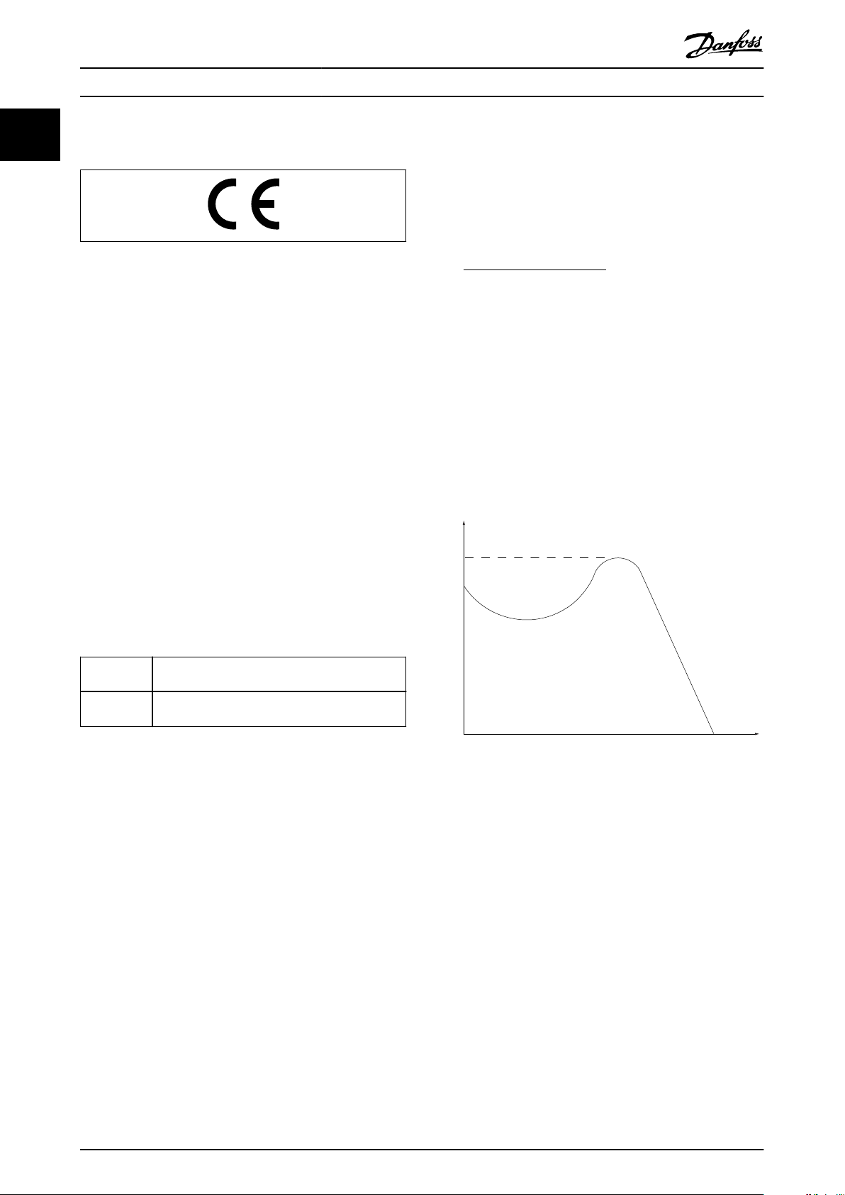
Pull-out
RPM
Torque
Introduction VLT® AutomationDrive FC 361
11
1.1.4 Approvals and Certications
I
M,N
Nominal motor current (nameplate data).
n
M,N
Nominal motor speed (nameplate data).
n
s
Synchronous motor speed.
2 × Parameter 1−23 × 60s
1.2 Denitions
1.2.1 Frequency Converter
Coast
The motor shaft is in free mode. No torque on the motor.
I
VLT,MAX
Maximum output current.
I
VLT,N
Rated output current supplied by the frequency converter.
U
VLT,MAX
Maximum output voltage.
ns=
n
slip
Parameter 1−39
Motor slip.
P
M,N
Rated motor power (nameplate data in kW or hp).
T
M,N
Rated torque (motor).
U
M
Instantaneous motor voltage.
U
M,N
Rated motor voltage (nameplate data).
Break-away torque
1.2.2 Input
Control commands
Start and stop the connected motor with the LCP and
digital inputs.
Functions are divided into 2 groups.
Functions in group 1 have higher priority than functions in
group 2.
Group 1 Coast stop, reset and coast stop, quick stop, DC
braking, stop, and [OFF].
Group 2 Start, latched start, start reversing, jog, freeze
output, and [Hand On].
Table 1.3 Function Groups
1.2.3 Motor
Motor running
Torque generated on the output shaft and speed from
0 RPM to maximum speed on the motor.
f
JOG
Motor frequency when the jog function is activated (via
digital terminals or bus).
f
M
Motor frequency.
f
MAX
Maximum motor frequency.
f
MIN
Minimum motor frequency.
f
M,N
Rated motor frequency (nameplate data).
I
M
Motor current (actual).
Illustration 1.1 Break-away Torque
η
VLT
The eciency of the frequency converter is dened as the
ratio between the power output and the power input.
Start-disable command
A start-disable command belonging to the control
commands in group 1. See Table 1.3 for more details.
Stop command
A stop command belonging to the control commands in
group 1. See Table 1.3 for more details.
1.2.4 References
Analog reference
A signal transmitted to the analog inputs 53 or 54 can be
voltage or current.
Binary reference
A signal transmitted via the serial communication port.
4 Danfoss A/S © 03/2019 All rights reserved. MG06J202
Page 7

Introduction Programming Guide
Preset reference
A dened preset reference to be set from -100% to +100%
of the reference range. Selection of 8 preset references via
the digital terminals. Selection of 4 preset references via
the bus.
Pulse reference
A pulse frequency signal transmitted to the digital inputs
(terminal 29 or 33).
Ref
MAX
Determines the relationship between the reference input at
100% full scale value (typically 10 V, 20 mA) and the
resulting reference. The maximum reference value is set in
parameter 3-03 Maximum Reference.
Ref
MIN
Determines the relationship between the reference input at
0% value (typically 0 V, 0 mA, 4 mA) and the resulting
reference. The minimum reference value is set in
parameter 3-02 Minimum Reference.
1.2.5 Miscellaneous
Analog inputs
The analog inputs are used for controlling various
functions of the frequency converter.
There are 2 types of analog inputs:
Current input: 0–20 mA and 4–20 mA.
•
Voltage input: 0–10 V DC.
•
Analog outputs
The analog outputs can supply a signal of 0–20 mA, or 4–
20 mA.
Automatic motor adaptation, AMA
The AMA algorithm determines the electrical parameters
for the connected motor at standstill.
Brake resistor
The brake resistor is a module capable of absorbing the
brake power generated in regenerative braking. This
regenerative brake power increases the DC-link voltage
and a brake chopper ensures that the power is transmitted
to the brake resistor.
CT characteristics
Constant torque characteristics used for all applications
such as conveyor belts, displacement pumps, and cranes.
Digital inputs
The digital inputs can be used for controlling various
functions of the frequency converter.
Digital outputs
The frequency converter features 2 solid-state outputs that
can supply a 24 V DC (maximum 40 mA) signal.
ETR
Electronic thermal relay is a thermal load calculation based
on present load and time. Its purpose is to estimate the
motor temperature.
FC standard bus
Includes RS485 bus with FC protocol or MC protocol. See
parameter 8-30 Protocol.
Initializing
If initializing is carried out (parameter 14-22 Operation Mode
or 2-nger reset), the frequency converter returns to the
default setting.
Intermittent duty cycle
An intermittent duty rating refers to a sequence of duty
cycles. Each cycle consists of an on-load and an o-load
period. The operation can be either periodic duty or nonperiodic duty.
LCP
The local control panel makes up a complete interface for
control and programming of the frequency converter. The
LCP is detachable. With the installation kit option, the LCP
can be installed up to 3 m (9.8 ft) from the frequency
converter in a front panel.
GLCP
The graphical local control panel interface for control and
programming of the frequency converter. The display is
graphical and the panel is used to show process values.
The GLCP has storing and copy functions.
NLCP
The numerical local control panel interface for control and
programming of the frequency converter. The display is
numerical and the panel is used to show process values.
The NLCP has storing and copy functions.
lsb
Least signicant bit.
msb
Most signicant bit.
MCM
Short for mille circular mil, an American measuring unit for
cable cross-section. 1 MCM = 0.5067 mm2.
On-line/o-line parameters
Changes to on-line parameters are activated immediately
after the data value is changed. To activate changes to o-
line parameters, press [OK].
Process PID
The PID control maintains speed, pressure, and
temperature by adjusting the output frequency to match
the varying load.
PCD
Process control data.
Power cycle
Switch o the mains until the display (LCP) is dark, then
turn power on again.
Power factor
The power factor is the relation between I1 and I
Power factor =
3xUxI1cosϕ1
3xUxI
RMS
RMS
.
1 1
MG06J202 Danfoss A/S © 03/2019 All rights reserved. 5
Page 8

Introduction VLT® AutomationDrive FC 361
11
For VLT® AutomationDrive FC 361 frequency converters,
cosϕ
1 = 1, therefore:
Power factor =
I1xcosϕ1
I
RMS
=
I
I
RMS
1
The power factor indicates to which extent the frequency
converter imposes a load on the mains supply.
The lower the power factor, the higher the I
RMS
for the
same kW performance.
I
RMS
= I
+ I
1
5
+ I
2
+ .. + I
7
2
n
2
2
In addition, a high power factor indicates that the dierent
harmonic currents are low.
The built-in DC coils produce a high power factor,
minimizing the imposed load on the mains supply.
STW
Status word.
THD
Total harmonic distortion states the total contribution of
harmonic distortion.
Thermistor
A temperature-dependent resistor placed where the
temperature is monitored (frequency converter or motor).
Trip
A state entered in fault situations, for example if the
frequency converter is subject to overvoltage or when it is
protecting the motor, process, or mechanism. Restart is
prevented until the cause of the fault has disappeared, and
the trip state is canceled by activating reset or, sometimes,
Pulse input/incremental encoder
An external, digital pulse transmitter used for feeding back
by being programmed to reset automatically. Do not use
trip for personal safety.
information on motor speed. The encoder is used in
applications where great accuracy in speed control is
required.
Trip lock
Trip lock is a state entered in fault situations when the
frequency converter is protecting itself and requiring
RCD
Residual current device.
Set-up
Save parameter settings in 4 set-ups. Change between the
2 parameter set-ups and edit 1 set-up while another set-up
is active.
SFAVM
Acronym describing the switching pattern stator uxoriented asynchronous vector modulation.
Slip compensation
The frequency converter compensates for the motor slip by
giving the frequency a supplement that follows the
measured motor load, keeping the motor speed almost
constant.
Smart logic control (SLC)
The SLC is a sequence of user-dened actions executed
when the smart logic controller evaluates the associated
user-dened events as true (parameter group 13-** Smart
physical intervention. An example causing a trip lock is the
frequency converter being subject to a short circuit on the
output. A locked trip can only be canceled by cutting o
mains, removing the cause of the fault, and reconnecting
the frequency converter. Restart is prevented until the trip
state is canceled by activating reset or, sometimes, by
being programmed to reset automatically. Do not use trip
lock for personal safety.
VT characteristics
Variable torque characteristics used for pumps and fans.
+
VVC
If compared with standard voltage/frequency ratio control,
voltage vector control (VVC+) improves the dynamics and
stability, both when the speed reference is changed and in
relation to the load torque.
60° AVM
°
Refers to the switching pattern 60
asynchronous vector
modulation.
Logic Control).
6 Danfoss A/S © 03/2019 All rights reserved. MG06J202
Page 9
e30bg500.12
91 (L1)
92 (L2)
93 (L3)
PE
50 (+10 V OUT)
53 (A IN)
54 (A IN)
55 (COM A IN)
0/4-20 mA
12 (+24 V OUT)
13 (+24 V OUT)
18 (D IN)
20
(COM D IN)
15 mA
200 mA
(U) 96
(V) 97
(W) 98
(PE) 99
(COM A OUT) 39
(A OUT) 42
0/4-20 mA
03
+10 V DC
0 to +10 V DC
0/4-20 mA
24 V DC
02
01
05
04
06
240 V AC, 2A
24 V (NPN)
0 V (PNP)
0 V (PNP)
24 V (NPN)
19 (D IN)
24 V (NPN)
0 V (PNP)
27
24V
0V
(D IN/OUT)
0 V (PNP)
24 V (NPN)
(D IN/OUT)
0V
24V
29
24 V (NPN)
0 V (PNP)
0 V (PNP)
24 V (NPN)
33 (D IN)
32 (D IN)
1
2
ON
A53 U-I (S201)
ON
2
1
A54 U-I (S202)
ON=0/4-20 mA
OFF=0 to ±10 V
95
400 V AC, 2A
P 5-00
+-+
-
(P RS485) 68
(N RS485) 69
(COM RS485) 61
0V5VS801
RS485
RS485
2
1
ON
S801/Bus Term.
OFF-ON
3-phase
power
input
Switch mode
power supply
Motor
Analog output
interface
Relay1
Relay2
ON=Terminated
OFF=Open
(NPN) = Sink
(PNP) = Source
240 V AC, 2A
400 V AC, 2A
0 to +10 V DC
10 V DC
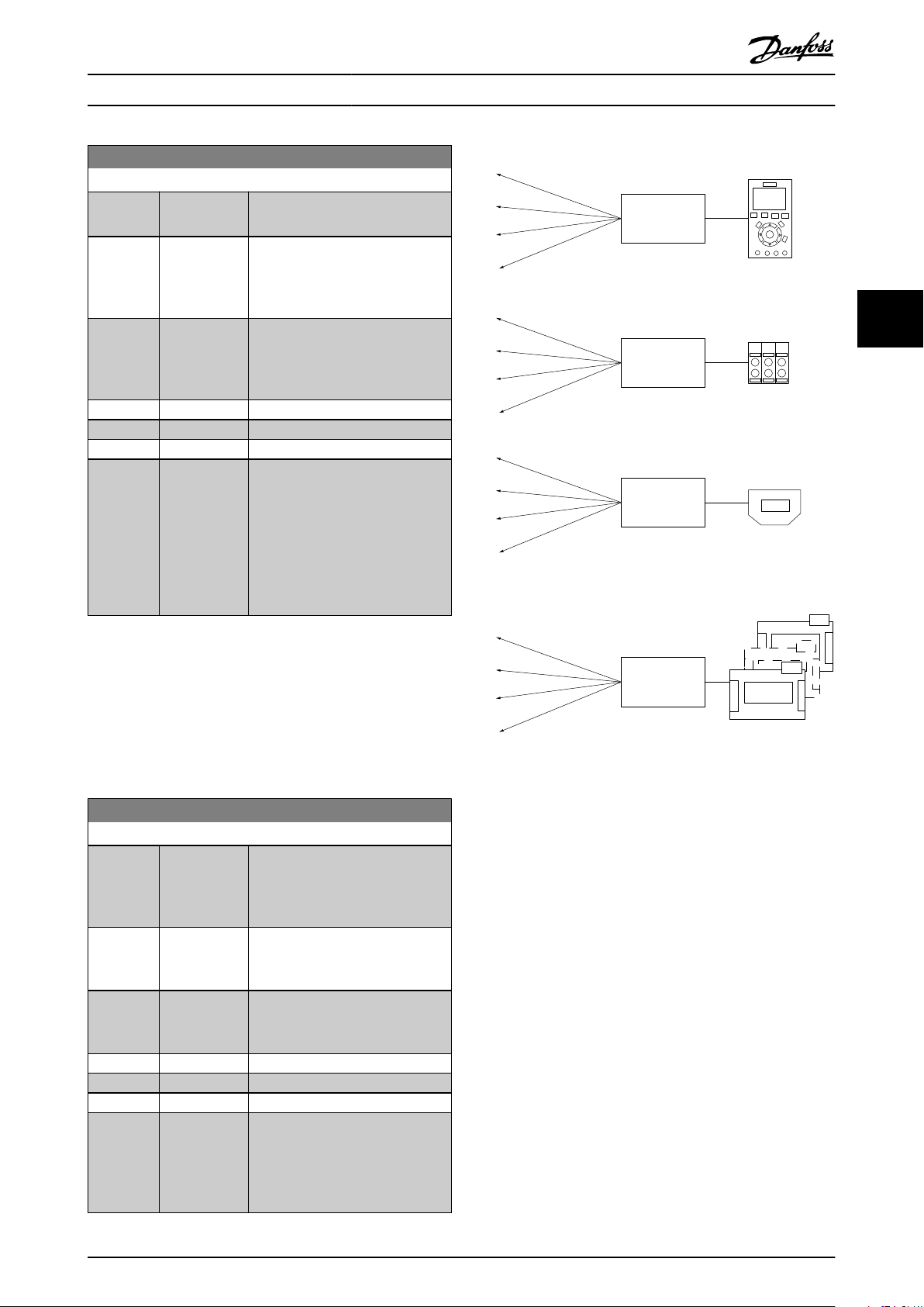
Introduction Programming Guide
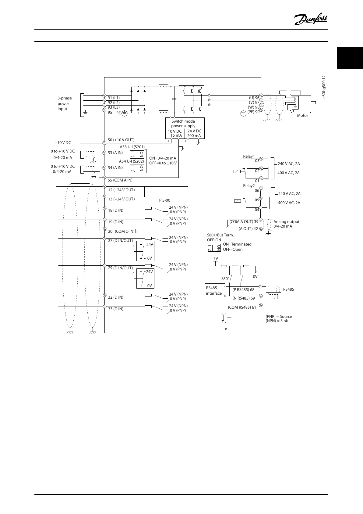
1.3 Electrical Wiring - Control Cables
1 1
Illustration 1.2 Basic Wiring Schematic Drawing
A=Analog, D=Digital
Very long control cables and analog signals may in rare cases, and depending on installation, result in 50/60 Hz ground
loops due to noise from mains supply cables.
If 50/60 Hz ground loops occur, consider breaking the shield or insert a 100 nF capacitor between shield and enclosure.
To avoid ground currents from both groups to aect other groups, connect the digital and analog inputs and outputs
separately to the common inputs (terminals 20, 55, and 39) of the frequency converter. For example, switching on the digital
input may disturb the analog input signal.
MG06J202 Danfoss A/S © 03/2019 All rights reserved. 7
Page 10
12
13
18
19
27
29
32
33
20
+24
VDC
0
VDC
PNP (S
our c e)
Dig
ital input wir
ing
e30bg750.10
NPN (Sink)
Dig
ital input wir
ing
12
13
18
19
27
29
32
33
20
+24
VDC
e30bg751.10
130BA681.10
12
13
18
32
27
19
29
33
20
P 5-12 [0]
P 5-10 [8]
S
tar
t/S t op
+24V
Speed
S
tar
t/S t op
[18]
e30bg752.10
Introduction VLT® AutomationDrive FC 361
11
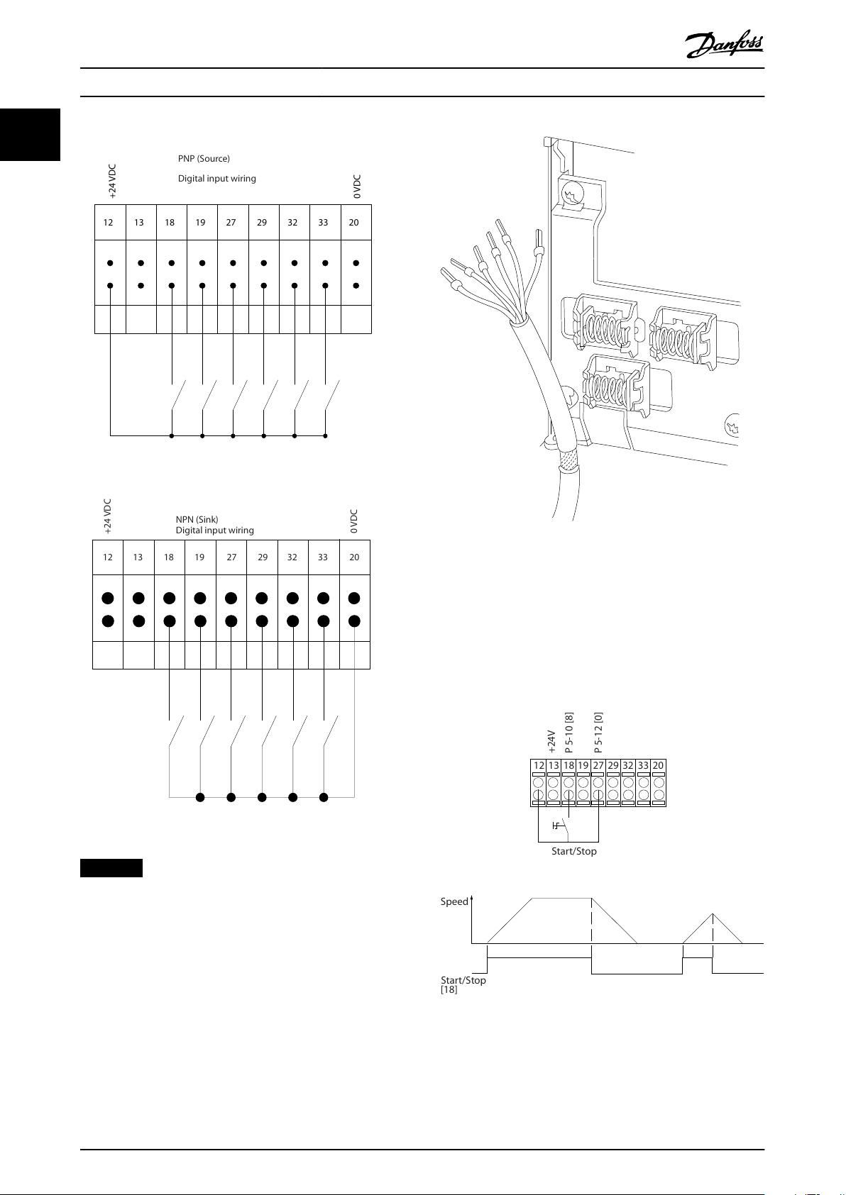
Input polarity of control terminals
Illustration 1.3 PNP (Source)
Illustration 1.5 Grounding of Shielded/Armored Control Cables
Illustration 1.4 NPN (Sink)
NOTICE
Control cables must be shielded/armored.
See the section Grounding of Shielded Control Cables in the
design guide for the correct termination of control cables.
1.3.1 Start/Stop
Terminal 18 = Parameter 5-10 Terminal 18 Digital Input [8]
Start.
Terminal 27 = Parameter 5-12 Terminal 27 Digital Input [0]
No operation (Default [2] Coast inverse).
Illustration 1.6 Start/Stop
8 Danfoss A/S © 03/2019 All rights reserved. MG06J202
Page 11
12
13
18
e30bg748.10
32
27
19
29
33
20
P 5 - 12 [6]
P 5 - 10[9]
+24V
Speed
S
tar t S t op in v erse
S
tar
t (18) S tar
t (27)
12
18
27
29
32
+24V
P
ar
. 5-10
P
ar
. 5-12 P ar
. 5-13 P ar
. 5-14
130BA154.11
555039 42 53 54
Speed RPM
P 6-15
1 kΩ
+10V/30mA
Ref. voltage
P 6-11 10V
Introduction Programming Guide
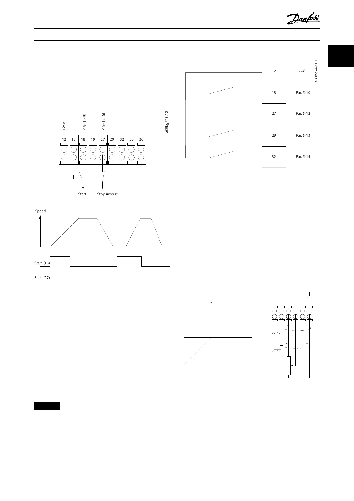
1.3.2 Pulse Start/Stop
Terminal 18 = Parameter 5-10 Terminal 18 Digital Input, [9]
Latched start.
Terminal 27 = Parameter 5-12 Terminal 27 Digital Input, [6]
Stop inverse.
1 1
Illustration 1.8 Speed up/Speed down
1.3.4 Potentiometer Reference
Voltage reference via a potentiometer
Reference source 1 = [1] Analog input 53 (default).
Terminal 53, low voltage = 0 V.
Terminal 53, high voltage = 10 V.
Terminal 53, low reference/feedback = 0 RPM.
Terminal 53, high reference/feedback = 1500 RPM.
Switch S201 = OFF (U)
Illustration 1.7 Pulse Start/Stop
1.3.3 Speed up/Speed Down
Terminals 29/32 = Speed up/Speed down
Terminal 18 = Parameter 5-10 Terminal 18 Digital
Input [9] Start (default).
Terminal 27 = Parameter 5-12 Terminal 27 Digital
Input [19] Freeze reference.
Terminal 29 = Parameter 5-13 Terminal 29 Digital
Input [21] Speed up.
Terminal 32 = Parameter 5-14 Terminal 32 Digital
Input [22] Speed down.
NOTICE
Terminal 29 only in FC x02 (x=series type).
Illustration 1.9 Potentiometer Reference
MG06J202 Danfoss A/S © 03/2019 All rights reserved. 9
Page 12
Safety VLT® AutomationDrive FC 361
2 Safety
22
2.1 Safety Symbols
The following symbols are used in this guide:
WARNING
Indicates a potentially hazardous situation that could
result in death or serious injury.
CAUTION
Indicates a potentially hazardous situation that could
result in minor or moderate injury. It can also be used to
alert against unsafe practices.
NOTICE
Indicates important information, including situations that
can result in damage to equipment or property.
2.2 Qualied Personnel
Correct and reliable transport, storage, installation,
operation, and maintenance are required for the troublefree and safe operation of the frequency converter. Only
qualied personnel are allowed to install and operate this
equipment.
Qualied personnel are dened as trained sta, who are
authorized to install, commission, and maintain equipment,
systems, and circuits in accordance with pertinent laws and
regulations. Also, the qualied personnel must be familiar
with the instructions and safety measures described in this
manual.
Safety regulations
Disconnect mains supply to the frequency
•
converter whenever repair work is to be carried
out. Check that the mains supply has been
disconnected and that the necessary time has
elapsed before removing motor and mains supply
plugs. See the warning of discharge time for
more information.
[O] does not disconnect the mains supply and
•
must not be used as a safety switch.
Ground the equipment properly, protect the user
•
against supply voltage, and protect the motor
against overload in accordance with applicable
national and local regulations.
The ground leakage current exceeds 3.5 mA.
•
Ensure correct grounding of the equipment by a
certied electrical installer.
Do not remove the plugs for the motor and
•
mains supply while the frequency converter is
connected to mains. Check that the mains supply
has been disconnected and that the necessary
time has elapsed before removing motor and
mains plugs.
The frequency converter has more voltage
•
sources than L1, L2, and L3, when load sharing
(linking of DC intermediate circuit) or external
24 V DC is installed. Check that all voltage
sources have been disconnected and that the
necessary time has elapsed before commencing
repair work. See the warning of discharge time
for more information.
Safety Precautions
2.3
WARNING
HIGH VOLTAGE
Drives contain high voltage when connected to AC mains
input, DC supply, or load sharing. Failure to perform
installation, start-up, and maintenance by qualied
personnel can result in death or serious injury.
Only qualied personnel must perform instal-
•
lation, start-up, and maintenance.
Before performing any service or repair work,
•
use an appropriate voltage measuring device to
make sure that there is no remaining voltage on
the drive.
10 Danfoss A/S © 03/2019 All rights reserved. MG06J202
Page 13

Safety Programming Guide
WARNING
UNINTENDED START
When the frequency converter is connected to AC mains,
DC supply, or load sharing, the motor may start at any
time. Unintended start during programming, service, or
repair work can result in death, serious injury, or
property damage. The motor can start via an external
switch, a serial bus command, an input reference signal
from the LCP, or after a cleared fault condition.
To prevent unintended motor start:
Disconnect the frequency converter from the
•
mains.
Press [O/Reset] on the LCP before
•
programming parameters.
Completely wire and assemble the frequency
•
converter, motor, and any driven equipment
before connecting the frequency converter to
AC mains, DC supply, or load sharing.
WARNING
DISCHARGE TIME
The frequency converter contains DC-link capacitors,
which can remain charged even when the frequency
converter is not powered. High voltage can be present
even when the warning LED indicator lights are o.
Failure to wait the specied time after power has been
removed before performing service or repair work can
result in death or serious injury.
Stop the motor.
•
Disconnect AC mains and remote DC-link power
•
supplies, including battery back-ups, UPS, and
DC-link connections to other frequency
converters.
Disconnect or lock PM motor.
•
Wait for the capacitors to discharge fully. The
•
minimum waiting time is 20 minutes.
Before performing any service or repair work,
•
use an appropriate voltage measuring device to
make sure that the capacitors are fully
discharged.
NOTICE
Hazardous situations must be identied by the machine
builder/integrator who is responsible for considering the
necessary preventive means. More monitoring and
protective devices may be included, always according to
valid national safety regulations, for example law on
mechanical tools and regulations for the prevention of
accidents.
Crane, lifts, and hoists
The controlling of external brakes must always have a
redundant system. The frequency converter can in no
circumstances be the primary safety circuit. Comply with
relevant standards, for example:
Hoists and cranes: IEC 60204-32.
Lifts: EN 81.
Protection mode
Once a hardware limit on motor current or DC-link voltage
is exceeded, the frequency converter enters the protection
mode. Protection mode means a change of the PWM
strategy and a low switching frequency to minimize losses.
This continues for 10 s after the last fault and increases the
reliability and the robustness of the frequency converter
while re-establishing full control of the motor.
In hoist applications, protection mode is not usable
because the frequency converter is unable to leave this
mode again and therefore it extends the time before
activating the brake, which is not recommended.
Protection mode can be disabled by setting
parameter 14-26 Trip Delay at Inverter Fault to 0, which
means that the frequency converter trips immediately if 1
of the hardware limits is exceeded.
NOTICE
Disabling protection mode in hoisting applications
(parameter 14-26 Trip Delay at Inverter Fault = 0) is
recommended.
2 2
NOTICE
Control signals from, or internally within, the frequency
converter may in rare cases be activated in error, be
delayed, or fail to occur entirely. When used in situations
where safety is critical, for example when controlling the
electromagnetic brake function of a hoist application, do
not rely on these control signals exclusively.
MG06J202 Danfoss A/S © 03/2019 All rights reserved. 11
Page 14
Auto
On
Reset
Hand
On
Off
Status
Quick
Menu
Main
Menu
Alarm
Log
Back
Cancel
Info
OK
Status
1(0)
1234rpm 10,4A 43,5Hz
Run OK
43,5Hz
On
Alarm
Warn.
e30ba018.14
1
2
3
4
b
a
c
Programming VLT® AutomationDrive FC 361
3 Programming
3.1 Graphical and Numerical Local Control
Panels
33
Easy programming of the frequency converter is done via
the graphical LCP (LCP 102). For information about using
the numerical local control panel (LCP 101), see
chapter 3.1.16 How to Program on the Numerical Local
Control Panel.
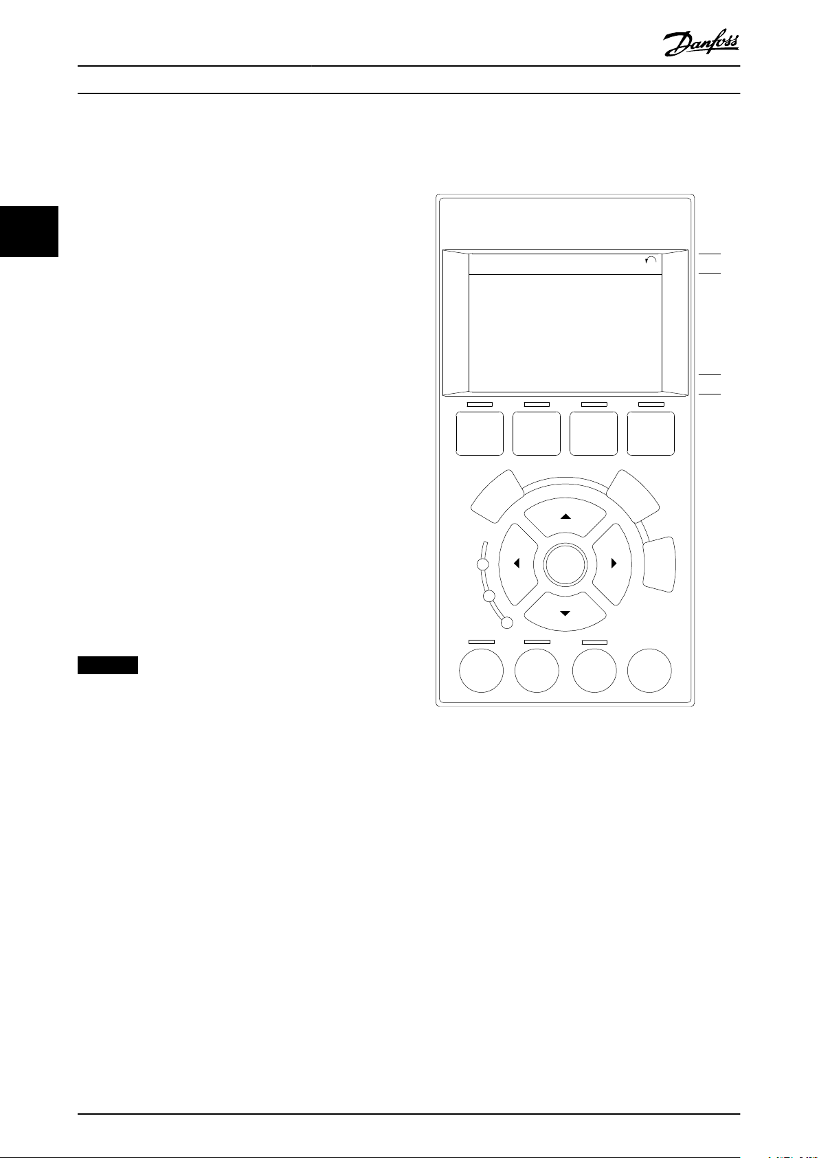
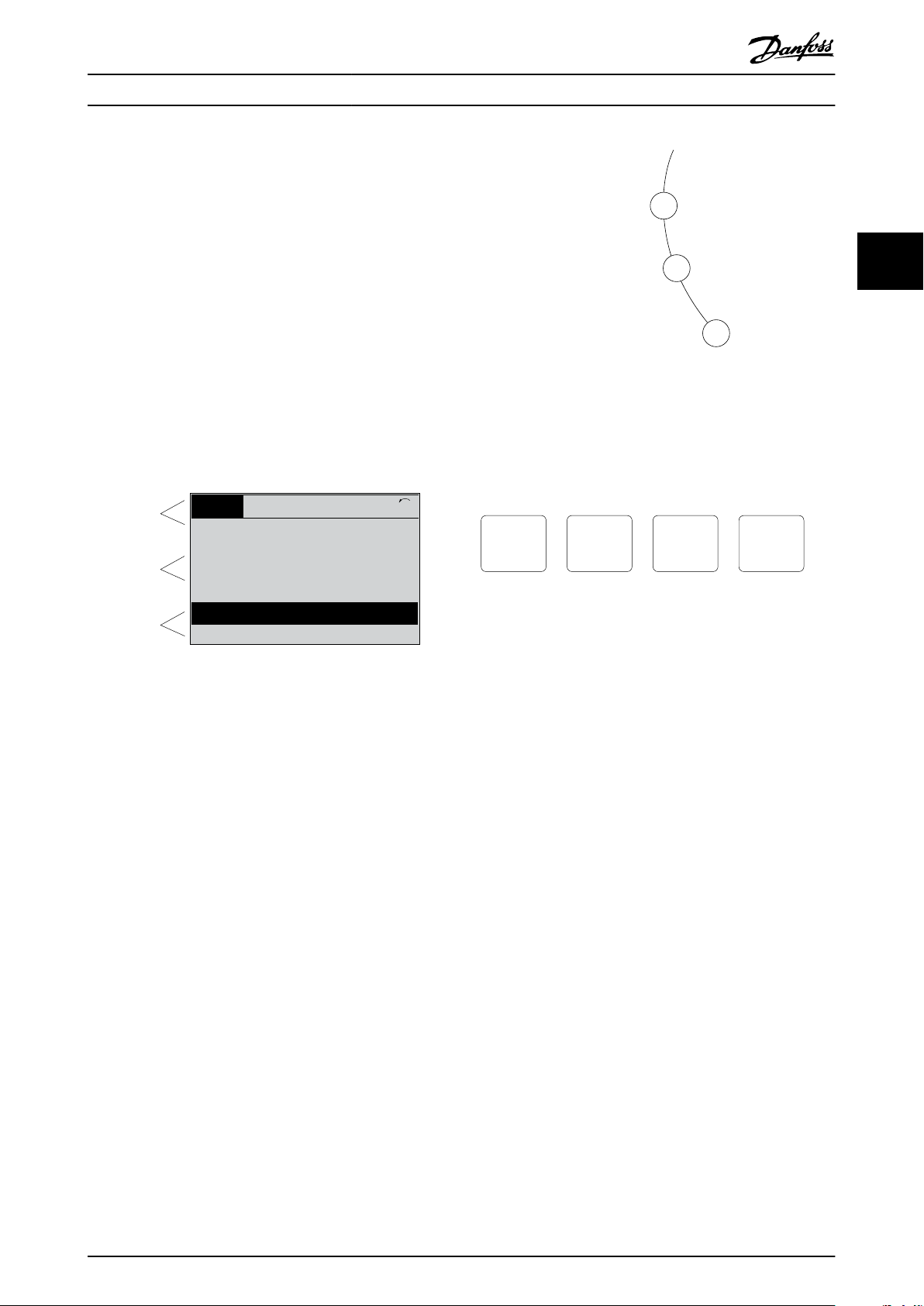
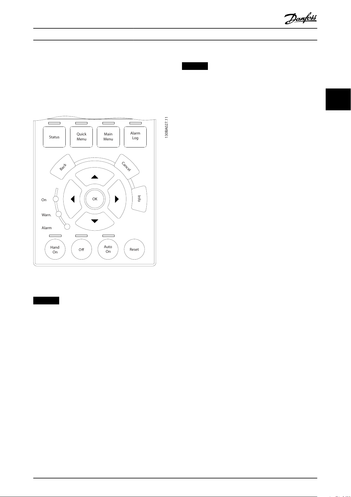
The LCP is divided into 4 functional groups:
1. Graphical display with status lines.
2. Menu keys and indicator lights - changing
parameters and switching between display
functions.
3. Navigation keys and indicator lights.
4. Operation keys and indicator lights.
The LCP display can show up to 5 items of operating data
while showing Status.
Display lines:
a. Status line: Status messages showing icons and
graphics.
b. Line 1–2: Operator data lines showing data
dened or selected. Add up to 1 extra line by
pressing [Status].
c. Status line: Status messages showing text.
NOTICE
If start-up is delayed, the LCP shows the INITIALIZING
message until it is ready. Adding or removing options
can delay the start-up.
Illustration 3.1 LCP
12 Danfoss A/S © 03/2019 All rights reserved. MG06J202
Page 15
Top section
Middle section
Bottom section
Status
43 RPM
1.4 Hz
Auto Remote Running
! Pwr.card temp (W29)
2.9%
5.44 A 25.3kW
1(1)
130BP074.10
!
On
Warn.
Alarm
130BP044.10
130BP045.10
Status
Quick
Menu
Main
Menu
Alarm
Log
Programming Programming Guide
3.1.1 LCD Display
The display has backlight and a total of 6 alpha-numeric
lines. The display lines show the direction of rotation
(arrow), the selected set-up, and the programming set-up.
The display is divided into 3 sections.
Top section
The top section shows up to 2 measurements in normal
operating status.
Middle section
The top line shows up to 5 measurements with related
unit, regardless of status (except in the case of alarm/
warning).
Bottom section
The bottom section always shows the state of the
frequency converter in Status mode.
3 3
Illustration 3.3 Indicator Lights
LCP keys
The control keys are divided into functions. The keys below
the display and indicator lights are used for parameter setup, including option of display indication during normal
operation.
Illustration 3.4 LCP Keys
Illustration 3.2 Display
The active set-up (selected as the active set-up in
parameter 0-10 Active Set-up) is shown. When programming
another set-up than the active set-up, the number of the
programmed set-up appears to the right.
Display contrast adjustment
Press [Status] and [▲] for darker display.
Press [Status] and [▼] for brighter display.
Most parameter set-ups can be changed immediately via
the LCP, unless a password has been created via
parameter 0-60 Main Menu Password or via
parameter 0-65 Quick Menu Password.
Indicator lights
If certain threshold values are exceeded, the alarm and/or
warning indicator lights up. A status and alarm text appear
on the LCP.
The ON indicator light is activated when the frequency
converter receives mains voltage or via a DC bus terminal
or 24 V external supply. At the same time, the back
indicator light is on.
Green LED/On: Control section is working.
•
Yellow LED/Warn: Indicates a warning.
•
Flashing Red LED/Alarm: Indicates an alarm.
•
MG06J202 Danfoss A/S © 03/2019 All rights reserved. 13
[Status]
Indicates the status of the frequency converter and/or the
motor. Select between 3 dierent readouts by pressing
[Status]: 5 line readouts, 4 line readouts, or smart logic
control.
Press [Status] for selecting the mode of display or for
changing back to display mode from either the quick
menu mode, the main menu mode, or the alarm mode.
Also use [Status] to toggle single or double readout mode.
[Quick Menu]
Allows quick access to dierent quick menus such as:
My personal menu.
•
Quick set-up.
•
Changes made.
•
Loggings.
•
Press [Quick Menu] to program the parameters belonging
to the Quick Menu. It is possible to switch directly
between quick menu mode and main menu mode.
[Main Menu]
Is used for programming all parameters.
It is possible to switch directly between main menu mode
and quick menu mode.
Parameter shortcut can be carried out by pressing down
[Main Menu] for 3 s. The parameter shortcut allows direct
access to any parameter.
Page 16

B
a
c
k
C
a
n
c
e
l
I
n
f
o
e30bp046.12
Hand
On
Off
Auto
On
Reset
Programming VLT® AutomationDrive FC 361
[Alarm Log]
Shows an alarm list of the 5 latest alarms (numbered A1–
A5). To obtain extra details about an alarm, press the
navigation keys to maneuver to the alarm number and
press [OK]. Information is shown about the condition of
the frequency converter before it enters the alarm mode.
33
[Back]
Returns to the previous step or layer in the navigation
structure.
[Cancel]
Last change or command is canceled as long as the display
has not been changed.
[Info]
Supplies information about a command, parameter, or
function in any display window. [Info] provides detailed
information whenever help is needed.
Exit Info mode by pressing either [Info], [Back], or [Cancel].
Illustration 3.5 Back
[Hand On]
Enables control of the frequency converter via the LCP.
[Hand On] also starts the motor, and it is now possible to
enter the motor speed data with the navigation keys. The
key can be selected as [1] Enable or [0] Disable via
parameter 0-40 [Hand on] Key on LCP.
External stop signals activated with control signals or a
eldbus override a start command via the LCP.
The following control signals are still active when [Hand
On] is activated:
[Hand On] - [O] - [Auto On].
•
Reset.
•
Coast stop inverse.
•
Reversing.
•
Set-up select bit 0 - Set-up select bit 1.
•
Stop command from serial communication.
•
Quick stop.
•
DC brake.
•
[O]
Stops the connected motor. The key can be selected as [1]
Enable or [0] Disable via parameter 0-41 [O] Key on LCP. If
no external stop function is selected and the [O] key is
inactive, the motor can be stopped by disconnecting the
voltage.
Illustration 3.6 Cancel
[Auto On]
Enables the frequency converter to be controlled via the
control terminals and/or serial communication. When a
start signal is applied on the control terminals and/or the
bus, the frequency converter starts. The key can be
selected as [1] Enable or [0] Disable via
Illustration 3.7 Info
parameter 0-42 [Auto on] Key on LCP.
NOTICE
An active HAND-OFF-AUTO signal via the digital inputs
Navigation keys
The 4 navigation keys are used to navigate between the
dierent options available in Quick Menu, Main Menu, and
Alarm Log. Press the keys to move the cursor.
[OK]
Press for selecting a parameter marked by the cursor and
for enabling the change of a parameter.
Local control keys
Local control keys are at the bottom of the LCP.
has higher priority than the control keys [Hand On] –
[Auto On].
[Reset]
Is used for resetting the frequency converter after an alarm
(trip). It can be selected as [1] Enable or [0] Disable via
parameter 0-43 [Reset] Key on LCP.
The parameter shortcut can be carried out by pressing
down the [Main Menu] key for 3 s. The parameter shortcut
provides direct access to any parameter.
Illustration 3.8 Local Control Keys
14 Danfoss A/S © 03/2019 All rights reserved. MG06J202
Page 17
Au t o
On R eset
Hand
On
S
ta
tus
Q
uick
M
enu
M
ain
M
enu
A
lar
m
Lo
g
Back
C
anc
el
I
n
fo
OK
On A lar m W
ar
n.
130BA027.11
Programming Programming Guide
3.1.2 Quick Transfer of Parameter Settings
between Multiple Frequency
Converters
Once the set-up of a frequency converter is complete,
store the data in the LCP or on a PC via MCT 10 Set-up
Software.
Data transfer from LCP to frequency converter
NOTICE
Stop the motor before performing this operation.
To transfer the data from the LCP to the frequency
converter:
1. Go to parameter 0-50 LCP Copy.
3 3
2. Press the [OK] key.
3. Select [2] All from LCP.
4. Press the [OK] key.
The parameter settings stored in the LCP are now
transferred to the frequency converter indicated by the
progress bar. When 100% is reached, press [OK].
3.1.3 Display Mode
In normal operation, up to 5 dierent operating variables
can be indicated continuously in the middle section: 1.1,
1.2, and 1.3, as well as 2 and 3.
3.1.4 Display Mode - Selection of Readouts
It is possible to toggle between 3 status readout screens
by pressing [Status].
Operating variables with dierent formatting are shown in
each status view further in this section.
Illustration 3.9 LCP
Data storage in LCP
NOTICE
Stop the motor before performing this operation.
To store the data in the LCP:
1. Go to parameter 0-50 LCP Copy.
2. Press the [OK] key.
3. Select [1] All to LCP.
4. Press the [OK] key.
All parameter settings are now stored in the LCP indicated
by the progress bar. When 100% is reached, press [OK].
Connect the LCP to another frequency converter and copy
the parameter settings to this frequency converter as well.
Table 3.1 shows the measurements that can be linked to
each of the operating variables. When options are
mounted, additional measurements are available.
Dene the links via
Parameter 0-20 Display Line 1.1 Small.
•
Parameter 0-21 Display Line 1.2 Small.
•
Parameter 0-22 Display Line 1.3 Small.
•
Parameter 0-23 Display Line 2 Large.
•
Parameter 0-24 Display Line 3 Large.
•
Each readout parameter selected in parameter 0-20 Display
Line 1.1 Small to parameter 0-24 Display Line 3 Large has its
own scale and digits after a possible decimal point. The
larger the numeric value of a parameter is, the fewer digits
are shown after the decimal point.
Example: Current readout 5.25 A, 15.2 A, 105 A.
MG06J202 Danfoss A/S © 03/2019 All rights reserved. 15
Page 18

1.1
2
3
1.3
1.2
130BP041.10
799 RPM
Auto Remote Ramping
1 (1)
36.4 kw7.83 A
0.000
53.2 %
Status
1.1
1.2
2
1.3
130BP062.10
207RPM
Auto Remote Running
1 (1)
24.4 kW5.25A
6.9
Hz
Status
Programming VLT® AutomationDrive FC 361
Operating variable Unit
Parameter 16-00 Control Word hex
Parameter 16-01 Reference [Unit] [Unit]
Parameter 16-02 Reference [%] %
Parameter 16-03 Status Word hex
33
Parameter 16-05 Main Actual Value [%] %
Parameter 16-09 Custom Readout
Parameter 16-10 Power [kW] [kW]
Parameter 16-11 Power [hp] [hp]
Parameter 16-12 Motor Voltage [V]
Parameter 16-13 Frequency [Hz]
Parameter 16-14 Motor current [A]
Parameter 16-15 Frequency [%]
Parameter 16-16 Torque [Nm] Nm
Parameter 16-17 Speed [RPM] [RPM]
Parameter 16-18 Motor Thermal %
Parameter 16-20 Motor Angle
Parameter 16-21 Torque [%] High Res.
Parameter 16-22 Torque [%]
Parameter 16-24 Calibrated Stator Resistance
Parameter 16-30 DC Link Voltage V
Parameter 16-34 Heatsink Temp.
Parameter 16-35 Inverter Thermal %
Parameter 16-36 Inv. Nom. Current A
Parameter 16-37 Inv. Max. Current A
Parameter 16-38 SL Controller State
Parameter 16-39 Control Card Temp.
Parameter 16-40 Logging Buer Full
Parameter 16-45 Motor Phase U Current
Parameter 16-46 Motor Phase V Current
Parameter 16-47 Motor Phase W Current
Parameter 16-48 Speed Ref. After Ramp [RPM]
Parameter 16-49 Current Fault Source
Parameter 16-50 External Reference
Parameter 16-51 Pulse Reference
Parameter 16-52 Feedback[Unit] [Unit]
Parameter 16-53 Digi Pot Reference
Parameter 16-57 Feedback [RPM]
Parameter 16-60 Digital Input bin
Parameter 16-61 Terminal 53 Switch Setting V
Parameter 16-62 Analog Input 53
Parameter 16-63 Terminal 54 Switch Setting V
Parameter 16-64 Analog Input 54
Parameter 16-65 Analog Output 42 [mA] [mA]
Parameter 16-66 Digital Output [bin] [bin]
Parameter 16-67 Pulse Input #29 [Hz] [Hz]
Parameter 16-68 Freq. Input #33 [Hz] [Hz]
Parameter 16-69 Pulse Output #27 [Hz] [Hz]
Parameter 16-70 Pulse Output #29 [Hz] [Hz]
Parameter 16-71 Relay Output [bin]
Parameter 16-72 Counter A
Parameter 16-73 Counter B
Parameter 16-75 Analog In X30/11
16 Danfoss A/S © 03/2019 All rights reserved. MG06J202
°C
°C
Operating variable Unit
Parameter 16-76 Analog In X30/12
Parameter 16-77 Analog Out X30/8 [mA]
Parameter 16-80 Fieldbus CTW 1 hex
Parameter 16-82 Fieldbus REF 1 hex
Parameter 16-84 Comm. Option ST W hex
Parameter 16-85 FC Port CTW 1 hex
Parameter 16-86 FC Port REF 1 hex
Parameter 16-87 Bus Readout Alarm/Warning
Parameter 16-90 Alarm Word
Parameter 16-91 Alarm Word 2
Parameter 16-92 Warning Word
Parameter 16-93 Warning Word 2
Parameter 16-94 Ext. Status Word
Parameter 16-95 Ext. Status Word 2
Parameter 16-97 Alarm Word 3
Parameter 16-98 Warning Word 3
Table 3.1 Units
Status view I
This readout state is standard after start-up or initialization.
Press [Info] to obtain information about the units linked to
the shown operating variables (1.1, 1.2, 1.3, 2 and 3).
See the operating variables shown in Illustration 3.10.
Illustration 3.10 Status View I
Status view II
See the operating variables (1.1, 1.2, 1.3, and 2) shown in
Illustration 3.11.
In the example, speed, motor current, motor power, and
frequency are selected as variables in the 1st and 2nd lines.
Illustration 3.11 Status View II
Page 19

130BP063.10
778 RPM
Auto Remote Running
1 (1)
4.0 kW0.86 A
State: 0 o 0 (o)
When: Do: -
Status
130BC916.10
Q1 My Personal Menu
Q2 Quick Setup
Q4 Smart Setup
Q5 Changes Made
0RPM 0.00A 1(1)
Quick Menus
Programming Programming Guide
Status view III
This state shows the event and action of the smart logic
control. For further information, see
chapter 4.12 Parameters: 13-** Smart Logic Control.
Illustration 3.12 Status View III
3.1.5 Parameter Set-up
The frequency converter can be used for practically all
assignments and oers 2 programming mode options:
Main menu mode.
•
Quick menu mode.
•
Main menu provides access to all parameters. Quick menu
takes the user through a few parameters, making it
possible to start operating the frequency converter.
Change a parameter in either main menu mode or quick
menu mode.
Parameter Setting
Parameter 0-01 Language
Parameter 1-20 Motor Power [kW] [kW]
Parameter 1-22 Motor Voltage [V ]
Parameter 1-23 Motor Frequency [Hz]
Parameter 1-24 Motor Current [A]
Parameter 1-25 Motor Nominal Speed [RPM]
Parameter 3-02 Minimum Reference [RPM]
Table 3.2 Selection of Parameter
1) If terminal 27 is set to [0] No function, no connection to +24 V on
terminal 27 is necessary.
Select Changes made to get information about:
The last 10 changes. Use the [▲] [▼] navigation
•
keys to scroll between the last 10 changed
parameters.
The changes made since default setting.
•
Select Loggings to get information about the shown line
readouts. The information is shown as graphs.
Only parameters selected in parameter 0-20 Display Line 1.1
Small and parameter 0-24 Display Line 3 Large can be
viewed. It is possible to store up to 120 samples in the
memory for later reference.
3 3
3.1.6 Quick Menu Key Functions
Press [Quick Menu] to enter a list of dierent areas
contained in the Quick Menu.
Select Q1 My Personal Menu to show the selected personal
parameters. These parameters are selected in
parameter 0-25 My Personal Menu. Up to 50 dierent
parameters can be added in this menu.
Illustration 3.13 Quick Menus
Select Q2 Quick Setup to go through a selection of
parameters to get the motor running almost optimally. The
default settings for the other parameters consider the
required control functions and the conguration of signal
inputs/outputs (control terminals).
The parameter selection is eected with the navigation
keys. The parameters in Table 3.2 are accessible.
MG06J202 Danfoss A/S © 03/2019 All rights reserved. 17
Page 20
Quick
Menu
OK
OK
OK
OK
OK
OK
OK
OK
OK
OK
OK
OK
OK
OK
Programming VLT® AutomationDrive FC 361
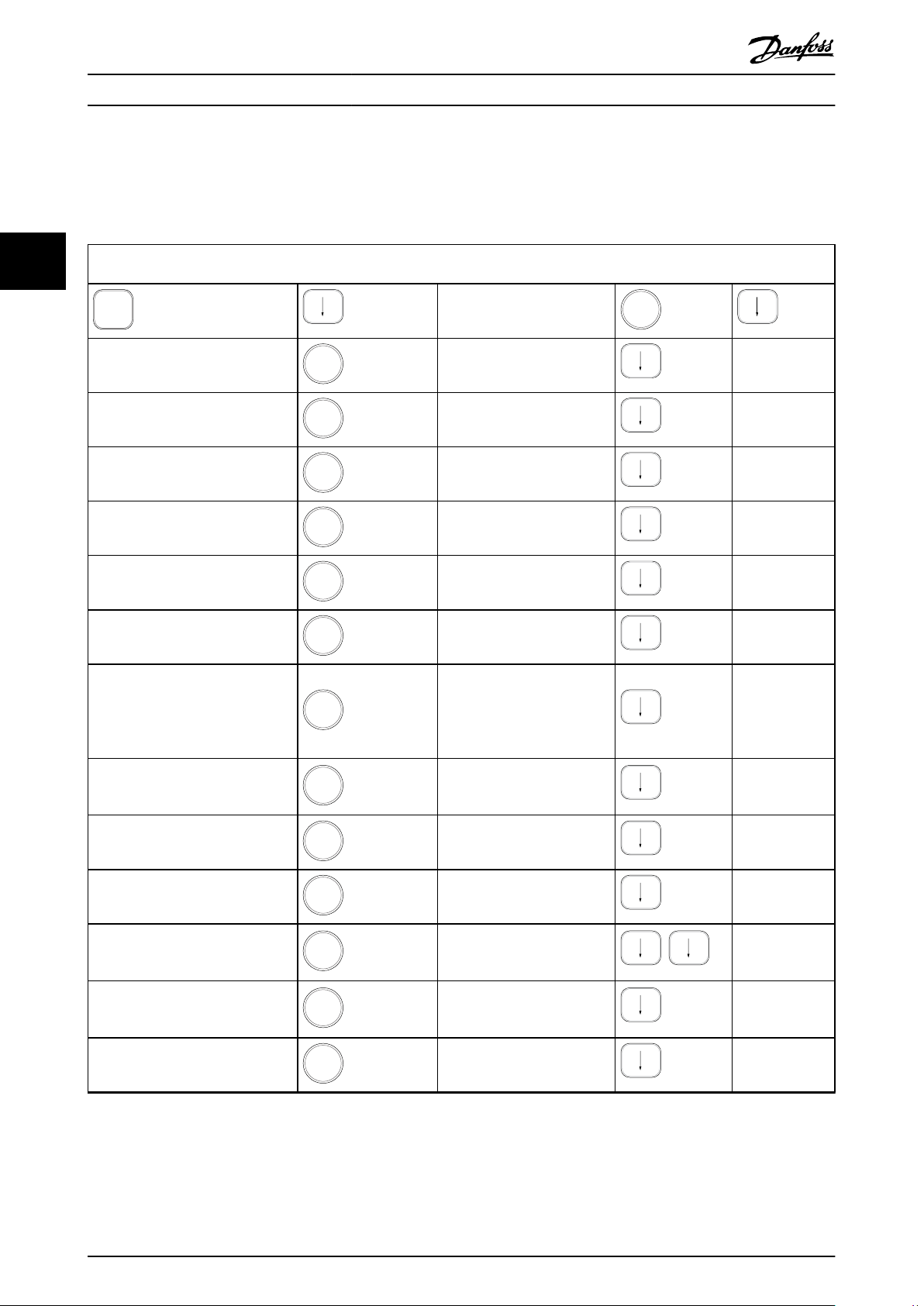
3.1.7 Initial Commissioning
The easiest way of carrying out the initial commissioning is by pressing [Quick Menu] and following the quick set-up
procedure using LCP 102 (read Table 3.3 from left to right). The example applies to open-loop applications.
33
Press
Q2 Quick Menu.
Parameter 0-01 Language
Parameter 1-20 Motor Power [kW]
Parameter 1-22 Motor Voltage
Parameter 1-23 Motor Frequency
Parameter 1-24 Motor Current
Parameter 1-25 Motor Nominal Speed
Set language.
Set motor nameplate power.
Set nameplate voltage.
Set nameplate frequency.
Set nameplate current.
Set nameplate speed in RPM.
If terminal default is [2] Coast
Parameter 5-12 Terminal 27 Digital
Input
inverse, it is possible to change
this setting to [0] No function.
No connection to terminal 27 is
then needed for running AMA.
Parameter 1-29 Automatic Motor
Adaptation (AMA)
Set desired AMA function.
Enable complete AMA is
recommended.
Parameter 3-02 Minimum Reference
Parameter 3-03 Maximum Reference
Set the minimum speed of the
motor shaft.
Set the maximum speed of the
motor shaft.
Set the ramp-up time with
Parameter 3-41 Ramp 1 Ramp Up Time
Parameter 3-42 Ramp 1 Ramp Down
Time
Parameter 3-13 Reference Site
reference to synchronous motor
speed, ns.
Set the ramp-down time with
reference to synchronous motor
speed, ns.
Set the site from where the
reference must work.
Table 3.3 Quick Set-up Procedure
18 Danfoss A/S © 03/2019 All rights reserved. MG06J202
Page 21
e30bp066.14
0-** Operation/Display
1-** Load/Motor
2-** Brakes
1107 RPM 3.84 A
Main Menu
1(1)
3-** References/Ramps
130BP067.10
740RPM
0 -01 Language
[0] English
10.64A 1 [1]
0-0
*
Basic Settings
130BP068.10
740RPM
0 -01 Language
[0] English
10.64 A 1 [1]
0-0
*
Basic Settings
Programming Programming Guide
Another easy way of commissioning the frequency
converter is by using the smart application set-up (SAS),
which can also be found by pressing [Quick Menu]. To set
up the applications listed, follow the instructions on the
successive screens.
The [Info] key can be used throughout the SAS to see help
information for various selections, settings, and messages.
The following 3 applications are included:
Mechanical brake.
•
Conveyor.
•
Pump/fan.
•
The following 4 eldbusses can be selected:
PROFIBUS.
•
PROFINET.
•
DeviceNet.
•
EtherNet/IP.
•
NOTICE
The frequency converter ignores the start conditions
when SAS is active.
All parameters can be changed in the Main Menu.
However, depending on the conguration
(parameter 1-00 Conguration Mode), some parameters can
be hidden. For example, open loop hides all the PID
parameters, and other enabled options make more
parameter groups visible.
3 3
3.1.9 Parameter Selection
In the main menu mode, the parameters are divided into
groups. Select a parameter group with the navigation keys.
After selecting a parameter group, select a parameter with
the navigation keys.
The middle section on the display shows the parameter
number and name, and the selected parameter value.
NOTICE
The smart set-up runs automatically on the rst powerup of the frequency converter or after a reset to factory
settings. If no action is taken, the SAS screen automatically disappears after 10 minutes.
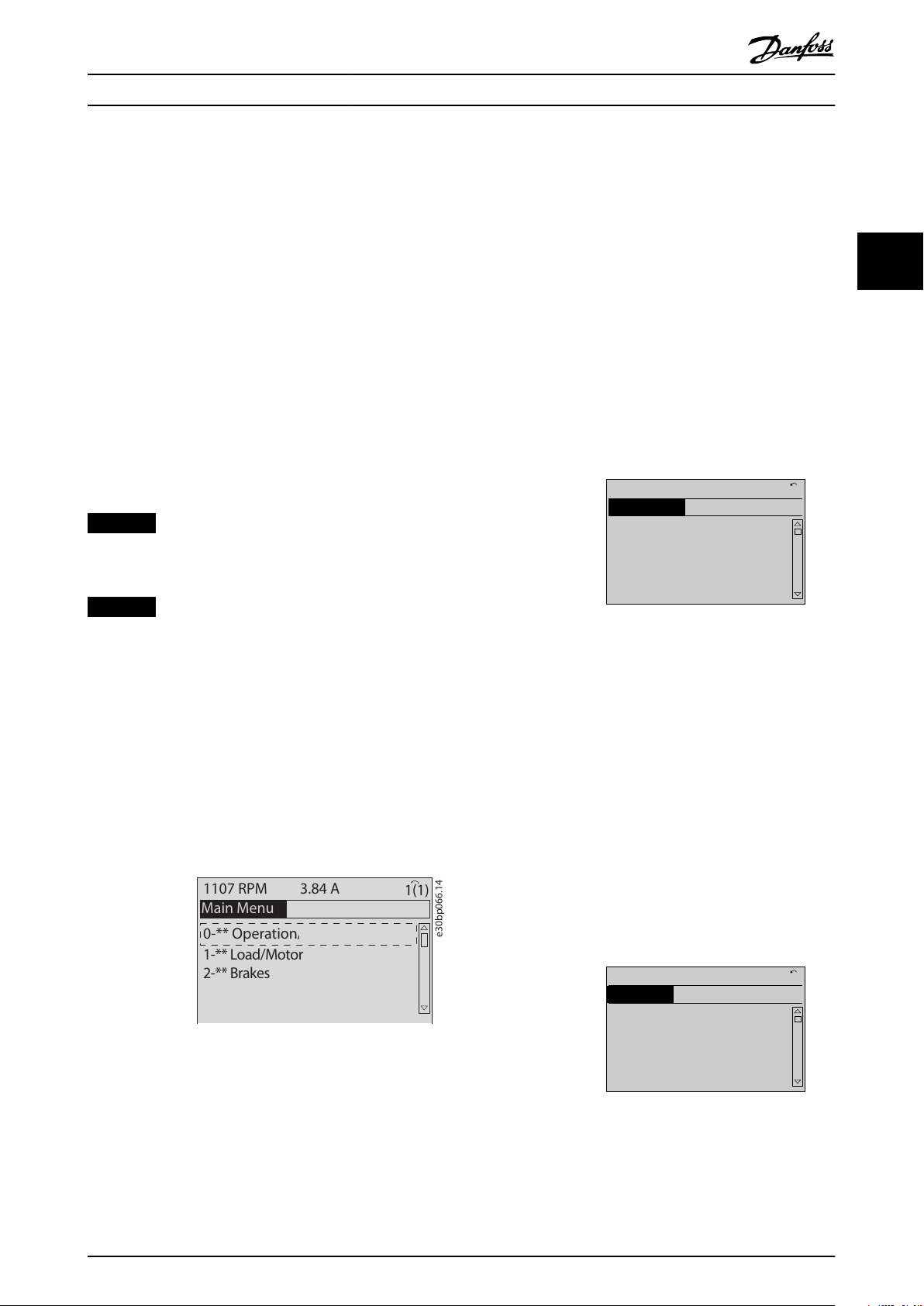
3.1.8 Main Menu Mode
Press [Main Menu] to enter the main menu mode. The
readout in Illustration 3.14 appears on the display.
The middle and bottom sections in the display show a list
of parameter groups, which can be selected by toggling
the [▲] and [▼] keys.
Illustration 3.14 Main Menu Mode
Illustration 3.15 Parameter Selection
3.1.10 Changing Data
The procedure for changing data is the same in the quick
menu mode and the main menu mode. Press [OK] to
change the selected parameter.
The procedure for changing data depends on whether the
selected parameter represents a numeric data value or a
text value.
3.1.11 Changing a Text Value
If the selected parameter is a text value, change the text
value with the [▲] [▼] keys.
Place the cursor on the value to save and press [OK].
Each parameter has a name and number, which remain the
same regardless of the programming mode. In the main
menu mode, the parameters are divided into groups. The
rst digit of the parameter number (from the left) indicates
the parameter group number.
MG06J202 Danfoss A/S © 03/2019 All rights reserved. 19
Illustration 3.16 Changing a Text Value
Page 22
130BP069.10
1- 6*
113 RPM 1.78 A 1(1)
Load depen. setting
1 - 60 Low speed load
compensation
100%
130BP070.10
1 - 60 Low speed load
compensation
1 0%
Load depen. setting 1- 6*
729RPM 6.21A 1(1)
6
130BP073.10
635 RPM
1 - 71 Start Delay
00.0s
0.44 A 1 (1)
1- 7*
Start Adjustments
130BP072.10
957RPM
1-71 High starting torque time
0. s
11.58A 1 (1)
1-7*Start Adjustments
4
Programming VLT® AutomationDrive FC 361
3.1.12 Changing a Data Value
If the selected parameter shows a numeric data value,
change the selected data value with the [◀] [▶] navigation
keys and the [▲] [▼] navigation keys. Press [◀] [▶] keys to
33
move the cursor horizontally.
Illustration 3.20 Saving
3.1.14 Value, Step by Step
Certain parameters can be changed step by step. This
applies to:
Parameter 1-20 Motor Power [kW].
•
Parameter 1-22 Motor Voltage.
Illustration 3.17 Changing a Data Value
Press the [
] [▼] keys to change the data value. [▲]
▲
increases the data value, and [▼] decreases the data value.
Place the cursor on the value to save and press [OK].
•
Parameter 1-23 Motor Frequency.
•
The parameters are changed both as a group of numeric
data values and as numeric data values that are innitely
varying.
3.1.15 Readout and Programming of
Indexed Parameters
Parameters are indexed when placed in a rolling stack.
Parameter 15-30 Fault Log: Error Code to
parameter 15-32 Alarm Log: Time contain a fault log, which
can be read out. Select a parameter, press [OK], and press
Illustration 3.18 Saving a Data Value
the [▲] [▼] keys to scroll through the value log.
For example, parameter 3-10 Preset Reference is changed as
3.1.13 Innitely Variable Change of
Numeric Data Value
follows:
1.
Select the parameter, press [OK], and press [▲] [▼]
to scroll through the indexed values.
If the selected parameter shows a numeric data value,
select a digit with [◀] [▶].
2. To change the parameter value, select the
indexed value and press [OK].
3.
Change the value by pressing [▲] [▼].
4. Press [OK] to accept the new setting.
5. Press [Cancel] to abort. Press [Back] to leave the
parameter.
3.1.16 How to Program on the Numerical
Local Control Panel
Illustration 3.19 Selecting a Digit
The following instructions are valid for the numerical LCP
(LCP 101).
Change the selected digit innitely variably with [▲] [▼].
The cursor indicates the selected digit. Place the cursor on
the digit to save and press [OK].
20 Danfoss A/S © 03/2019 All rights reserved. MG06J202
The control panel is divided into 4 functional groups:
Numerical display.
•
Menu keys and indicator lights - changing
•
parameters and switching between display
functions.
Navigation keys and indicator lights.
•
Operation keys and indicator lights.
•
Page 23
e30ba191.11
1
Auto
On
Reset
Hand
On
Off
Menu
Status
Quick
Setup
Main
Menu
Back
2
3
4
OK
On
Alarm
Warn.
Setup
130BP077.10
22.8
rpm
Setup 1
Setup 1
130BP078.10
A 17
Programming Programming Guide
Display line
Status messages showing icons and numeric value.
Indicator lights
Green LED/On: Indicates if control section is on.
•
Yellow LED/Wrn: Indicates a warning.
•
Flashing red LED/Alarm: Indicates an alarm.
•
LCP keys
[Menu]
Select 1 of the following modes:
Status.
•
Quick set-up.
•
Main menu.
•
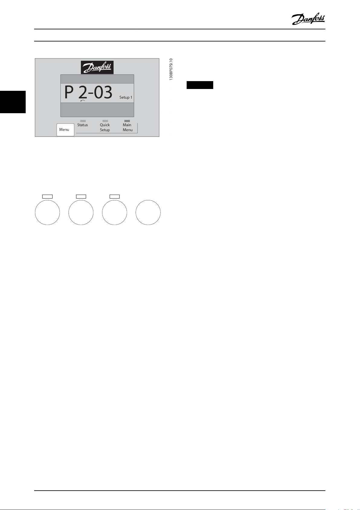
Status mode
Status mode shows the status of the frequency converter
or the motor.
If an alarm occurs, the NLCP automatically switches to
status mode.
Several alarms can be shown.
NOTICE
Parameter copy is not possible with LCP 101 numerical
local control panel.
Illustration 3.22 Status Mode
Illustration 3.23 Alarm
3 3
Main Menu/Quick Set-up
Used for programming all parameters or only the
parameters in the Quick Menu (see also description of the
LCP 102 in chapter 3.1 Graphical and Numerical Local
Control Panels).
When the value ashes, press [▲] or [▼] to change
parameter values.
Illustration 3.21 LCP Keys
1. Press [Main Menu] to select main menu.
2. Select the parameter group [xx-__] and press
[OK].
3. Select the parameter [__-xx] and press [OK].
4. If the parameter is an array parameter, select the
array number and press [OK].
5. Select the required data value and press [OK].
Parameters with functional options show values such as
[1], [2], and so on. For a description of the dierent
options, see the individual parameter descriptions in
chapter 4 Parameter Descriptions.
[Back]
Used for stepping backwards.
[▲] [▼] are used for maneuvering between commands and
within parameters.
MG06J202 Danfoss A/S © 03/2019 All rights reserved. 21
Page 24
e30bp046.12
Hand
On
Off
Auto
On
Reset
Programming VLT® AutomationDrive FC 361
frequency converter starts. The key can be selected as [1]
Enable or [0] Disable via parameter 0-42 [Auto on] Key on
LCP.
NOTICE
An active HAND-OFF-AUTO signal via the digital inputs
33
Illustration 3.24 Main Menu/Quick Set-up
has higher priority than the control keys [Hand On] and
[Auto On].
[Reset]
Used for resetting the frequency converter after an alarm
(trip). It can be selected as [1] Enable or [0] Disable via
parameter 0-43 [Reset] Key on LCP.
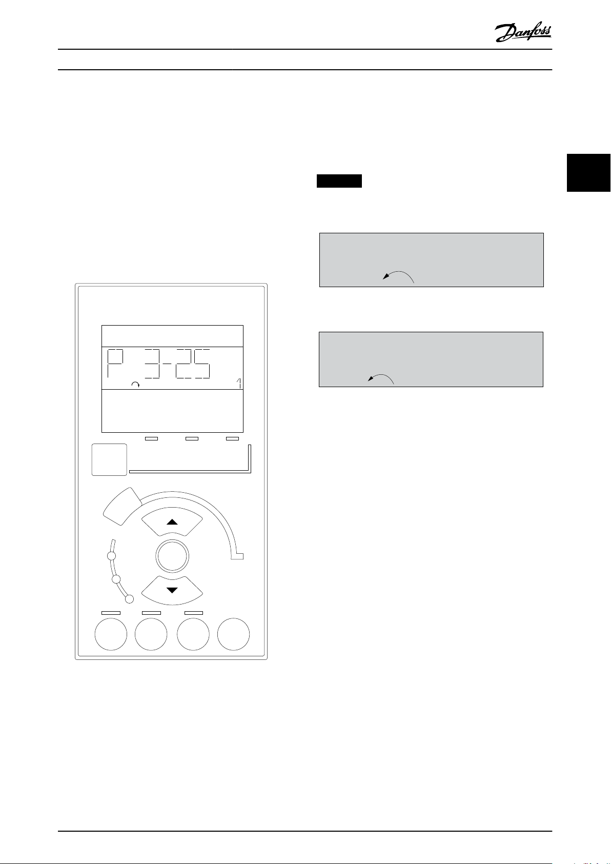
3.1.17 LCP Keys
Keys for local control are at the bottom of the LCP.
Illustration 3.25 LCP Keys
[Hand On]
Enables control of the frequency converter via the LCP.
[Hand On] also starts the motor and it is now possible to
enter the motor speed data with the navigation keys. The
key can be selected as [1] Enable or [0] Disable via
parameter 0-40 [Hand on] Key on LCP.
External stop signals activated with control signals, or a
eldbus, override a start command via the LCP.
The following control signals are still active when [Hand
On] is activated:
[Hand On] - [O] - [Auto On].
•
Reset.
•
Coast stop inverse.
•
Reversing.
•
Set-up select lsb - Set-up select msb.
•
Stop command from serial communication.
•
Quick stop.
•
DC brake.
•
[O]
Stops the connected motor. The key can be selected as [1]
Enable or [0] Disable via parameter 0-41 [O] Key on LCP.
If no external stop function is selected and the [O] key is
inactive, stop the motor by disconnecting the voltage.
[Auto On]
Enables control of the frequency converter via the control
terminals and/or serial communication. When a start signal
is applied on the control terminals and/or the bus, the
3.1.18 Initialization to Default Settings
Initialize the frequency converter to default settings in 2
ways.
Recommended initialization (via
parameter 14-22 Operation Mode)
1. Select parameter 14-22 Operation Mode.
2. Press [OK].
3. Select [2] initialization.
4. Press [OK].
5. Disconnect the mains supply and wait until the
display turns o.
6. Reconnect the mains supply. The frequency
converter is now reset.
Parameter 14-22 Operation Mode initializes all except:
Parameter 14-50 RFI Filter.
•
Parameter 8-30 Protocol.
•
Parameter 8-31 Address.
•
Parameter 8-32 FC Port Baud Rate.
•
Parameter 8-35 Minimum Response Delay.
•
Parameter 8-36 Max Response Delay.
•
Parameter 8-37 Max Inter-Char Delay.
•
Parameter 15-00 Operating hours to
•
parameter 15-05 Over Volt's.
Parameter 15-20 Historic Log: Event to
•
parameter 15-22 Historic Log: Time.
Parameter 15-30 Fault Log: Error Code to
•
parameter 15-32 Alarm Log: Time.
22 Danfoss A/S © 03/2019 All rights reserved. MG06J202
Page 25

Programming Programming Guide
Manual initialization
1. Disconnect from mains and wait until the display
turns o.
2. 2a Press [Status] - [Main Menu] - [OK] at
the same time while powering up the
LCP 102, graphical display.
2b Press [Menu] - [OK] while powering up
the LCP 101, numerical display.
3. Release the keys after 5 s.
4. The frequency converter is now programmed
according to default settings.
This procedure initializes all except:
Parameter 15-00 Operating hours.
•
Parameter 15-03 Power Up's.
•
Parameter 15-04 Over Temp's.
•
Parameter 15-05 Over Volt's.
•
NOTICE
A manual initialization also resets serial communication,
RFI lter settings (parameter 14-50 RFI Filter), and fault
log settings.
3 3
MG06J202 Danfoss A/S © 03/2019 All rights reserved. 23
Page 26
0-02 Motor Speed Unit
Option: Function:
NOTICE
This parameter cannot be
adjusted while the motor is
running.
The information shown in the
display depends on settings in
parameter 0-02 Motor Speed Unit.
The default settings of
parameter 0-02 Motor Speed Unit
depend on to which region of the
world the frequency converter is
supplied.
NOTICE
Changing the motor speed
unit resets certain parameters
to their initial value. Select the
motor speed unit before
modifying other parameters.
[0] RPM Select to show motor speed
variables and parameters using
motor speed (RPM).
[1] * Hz Select to show motor speed
variables and parameters using
output frequency (Hz).
0-04 Operating State at Power-up (Hand)
Option: Function:
Select the operating mode upon
reconnection of the frequency
converter to mains voltage after
power-down in hand-on mode.
0-04 Operating State at Power-up (Hand)
Option: Function:
[0] Resume Restart the frequency converter,
maintaining the start/stop settings
(applied by [Hand On/O]) selected
before power-down of the
frequency converter.
[1] * Forced stop,
ref=old
Restart the frequency converter
with a saved local reference after
mains voltage reappears and after
pressing [Hand On].
[2] Forced stop,
ref=0
Reset the local reference to 0 upon
restarting the frequency converter.
Parameter Descriptions VLT® AutomationDrive FC 361
4 Parameter Descriptions
4.1 Parameters: 0-** Operation and Display
Parameters related to the basic functions of the frequency
converter, function of the LCP keys, and conguration of
the LCP display.
44
4.1.1 0-0* Basic Settings
0-01 Language
Option: Function:
Denes the language to be used in the display.
[0] * English
[10] Chinese
24 Danfoss A/S © 03/2019 All rights reserved. MG06J202
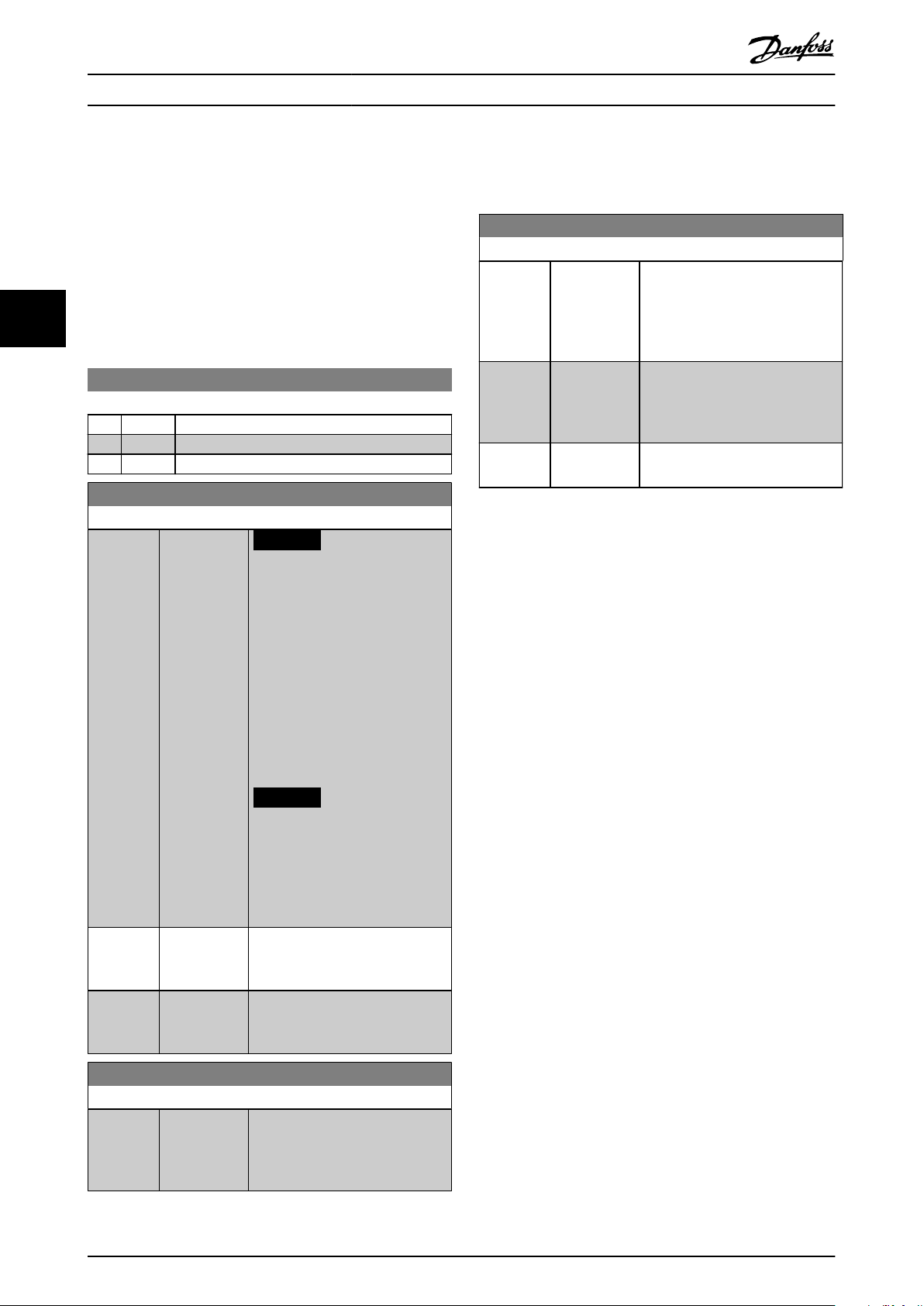
4.1.2 0-1* Set-up Operations
Dene and control the individual parameter set-ups.
The frequency converter has 4 parameter set-ups that can
be programmed independently of each other. This makes
the frequency converter very
advanced control functionality problems, often saving the
cost of external control equipment. Parameter set-ups can
be used to program the frequency converter to operate
according to 1 control scheme in 1 set-up (for example
motor 1 for horizontal movement) and another control
scheme in another set-up (for example motor 2 for vertical
movement). Alternatively, parameter set-ups can be used
by an OEM machine builder to identically program all their
factory-tted frequency converters for dierent machine
types within a range to have the same parameters. During
production/commissioning, simply select a specic set-up
depending on which machine the frequency converter is
installed on.
The active set-up (that is the set-up in which the frequency
converter is currently operating) can be selected in
parameter 0-10 Active Set-up and is shown in the LCP. By
using multi set-up, it is possible to switch between set-ups
with the frequency converter running, or it can be stopped
via digital input or serial communication commands. If it is
necessary to change set-ups while the frequency converter
is running, ensure that parameter 0-12 This Set-up Linked to
is programmed as required. By using parameter 0-11 Edit
Set-up, it is possible to edit parameters within any of the
set-ups while continuing the operation of the frequency
converter in its active set-up, which can be a dierent setup to the one being edited. By using parameter 0-51 Set-up
Copy, it is possible to copy parameter settings between the
set-ups to enable quicker commissioning if similar
parameter settings are required in dierent set-ups.
exible and able to solve
Page 27
0-10 Active Set-up
Option: Function:
Select the set-up to control the
frequency converter functions.
[0] Factory setup Cannot be changed. It contains the
Danfoss data set and can be used
as a data source when returning
the other set-ups to a known state.
[1] * Set-up 1 [1] Set-up 1 to [4] Set-up 4 are the 4
separate parameter set-ups within
which all parameters can be
programmed.
[2] Set-up 2
[3] Set-up 3
[4] Set-up 4
[9] Multi Set-up Remote set-up selections using
digital inputs and the serial
communication port. This set-up
uses the settings from
parameter 0-12 This Set-up Linked to.
Stop the frequency converter
before making changes to open
and closed-loop functions.
0-11 Edit Set-up
Option: Function:
Select the set-up to be edited (that
is programmed) during operation;
either the active set-up or 1 of the
inactive set-ups.
[0] Factory setup Cannot be edited but it is useful as
a data source to return the other
set-ups to a known state.
[1] * Set-up 1 [1] Set-up 1 to [4] Set-up 4 can be
edited freely during operation,
independently of the active set-up.
[2] Set-up 2
[3] Set-up 3
[4] Set-up 4
[9] Active Set-up Can also be edited during
operation. Edit the selected set-up
from a range of sources: LCP, FC
RS485, FC USB, or up to 5 eldbus
sites.
130BA199.10
1
2
3
4
1
2
3
4
1
2
3
4
1
2
3
4
P 0-11
P 0-11
P 0-11
P 0-11
Set-up
Set-up
Set-up
Set-up
PLC Fieldbus
Parameter Descriptions Programming Guide
4 4
Use parameter 0-51 Set-up Copy to copy a set-up to 1 or all
other set-ups. Stop the frequency converter before
switching between set-ups where parameters marked not
changeable during operation have dierent values. To avoid
conicting settings of the same parameter within 2
dierent set-ups, link the set-ups together using
parameter 0-12 This Set-up Linked to. Parameters which are
not changeable during operation are marked FALSE in the
parameter lists in chapter 5 Parameter Lists.
MG06J202 Danfoss A/S © 03/2019 All rights reserved. 25
Illustration 4.1 Edit Set-up
Page 28
0-12 This Set-up Linked to
Option: Function:
To enable conict-free changes
from 1 set-up to another during
operation, link set-ups containing
parameters which are not
changeable during operation. The
link ensures synchronizing of the
not changeable during operationparameter values when moving
from 1 set-up to another during
operation. Not changeable during
operation-parameters can be
identied by the label FALSE in the
parameter lists in
chapter 5 Parameter Lists.
Parameter 0-12 This Set-up Linked to
is used by [9] Multi set-up in
parameter 0-10 Active Set-up. Multi
set-up is used to move from 1 setup to another during operation
(that is while the motor is running).
Example:
Use multi set-up to shift from setup 1 to set-up 2 while the motor is
running. Program in set-up 1 rst,
then ensure that set-up 1 and setup 2 are synchronized (or linked).
Synchronization can be performed
in 2 ways:
1. Select the following options:
•
[2] Set-up 2 in
parameter 0-11 Edit Set-up.
•
[1] Set-up 1 in
parameter 0-12 This Set-up
Linked to.
This starts the linking (synchronizing) process.
130BP075.10
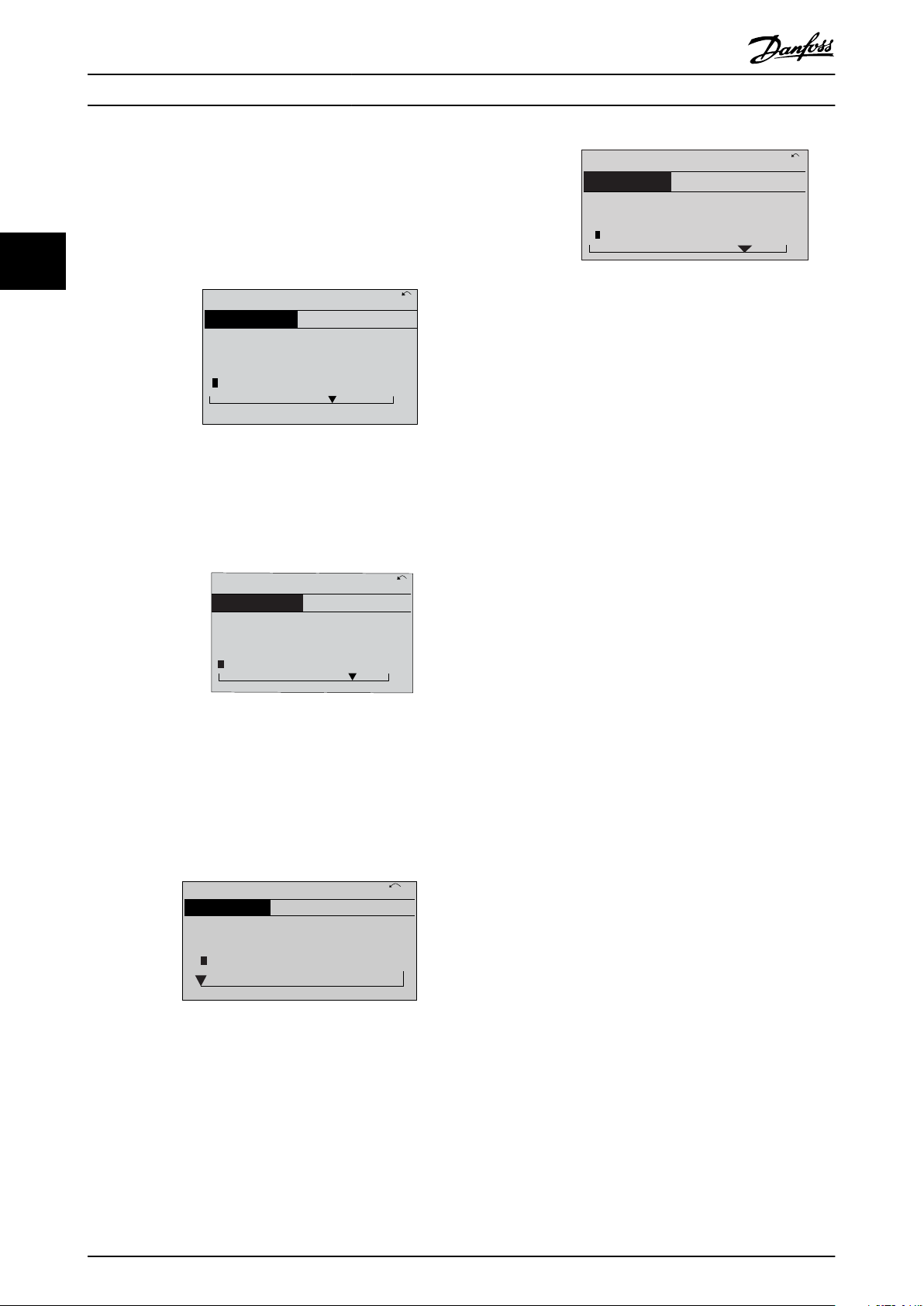
0-12 This Set-up Linked to
0 RPM
0.00A
1(1)
Set-up Handling 0-1*
[1]
Setup 1
Illustration 4.2 Set-up 1
OR
2. While still in set-up 1, copy setup 1 to set-up 2. Then set
parameter 0-12 This Set-up Linked to
to [2] Set-up 2. This starts the
linking process.
0-12 This Set-up Linked to
Option: Function:
130BP076.10
0-12 This Set-up Linked to
0 RPM
0.00A
1(1)
Set-up Handling
0-1*
[2]
Setup 2
Illustration 4.3 Set-up 2
When completed,
parameter 0-13 Readout: Linked Setups reads {1,2} to indicate that all
not changeable during operation-
parameters are now the same in
set-up 1 and set-up 2. If there are
changes to a not changeable during
operation parameter, for example
parameter 1-30 Stator Resistance (Rs),
in set-up 2, they are also changed
automatically in set-up 1. A switch
between set-up 1 and set-up 2
during operation is now possible.
[0] * Not linked
[1] Set-up 1
[2] Set-up 2
[3] Set-up 3
[4] Set-up 4
0-13 Readout: Linked Set-ups
Array [5]
Range: Function:
0* [0 - 255 ] View a list of all the set-ups linked
by parameter 0-12 This Set-up Linked
to. The parameter has 1 index for
each parameter set-up. The value
for each index shows which set-ups
are linked to that parameter set-up.
Index LCP value
0 {0}
1 {1,2}
2 {1,2}
3 {3}
4 {4}
Table 4.1 Set-up Link Example
Parameter Descriptions VLT® AutomationDrive FC 361
44
26 Danfoss A/S © 03/2019 All rights reserved. MG06J202
Page 29
0-14 Readout: Edit Set-ups / Channel
Range: Function:
0* [-2147483648
- 2147483647]
View the setting of
parameter 0-11 Edit Set-up for each
of the 4 dierent communication
channels. When the number is
shown as a hex number, as it is in
the LCP, each number represents 1
channel.
Numbers 1–4 represent a set-up
number; F means factory setting;
and A means active set-up. The
channels are, from right to left: LCP,
FC bus, USB, HPFB1-5.
Example: The number AAAAAA21h
means the following:
•
The frequency converter
received the setting set-up
2 via a eldbus channel.
This selection is reected
in parameter 0-11 Edit Set-
up.
•
A user selected set-up 1
via the LCP.
•
All other channels are
using the active set-up.
Parameter Descriptions Programming Guide
4.1.3 0-2* LCP Display
Dene the variables shown in the LCP.
NOTICE
For information on how to write display texts, refer to:
Parameter 0-37 Display Text 1.
•
•
•
0-20 Display Line 1.1 Small
Option: Function:
[0] None No display value selected.
[37] Display Text 1
[38] Display Text 2
[39] Display Text 3
[748] FCD Feed Forward
[953] Probus Warning
[1500] Operating Hours
[1501] Running Hours
[1502] kWh Counter
[1580] Fan Running Hours
MG06J202 Danfoss A/S © 03/2019 All rights reserved. 27
Parameter 0-38 Display Text 2.
Parameter 0-39 Display Text 3.
Word
Select a variable for display in line
1, left position.
0-20 Display Line 1.1 Small
Option: Function:
[1600] Control Word Present control word.
[1601] Reference [Unit] Total reference (sum of digital/
analog/preset/bus/freeze reference/
catch up and slow down) in
selected unit.
[1602] Reference % Total reference (sum of digital/
analog/preset/bus/freeze reference/
catch up and slow down) in
percent.
[1603] Status Word Present status word.
[1605] Main Actual Value
[%]
[1609] Custom Readout
[1610] Power [kW] Actual power consumed by the
[1611] Power [hp] Actual power consumed by the
[1612] Motor Voltage Voltage supplied to the motor.
[1613] Frequency Motor frequency, that is the output
[1614] Motor current Phase current of the motor
[1615] Frequency [%] Motor frequency, that is the output
[1616] Torque [Nm] Actual motor torque in Nm.
[1617]*Speed [RPM] Speed in RPM (revolutions per
[1618] Motor Thermal Thermal load on the motor,
[1620] Motor Angle
[1621] Torque [%] High
Res.
[1622] Torque [%] Present motor load as a percentage
[1624] Calibrated Stator
Resistance
[1630] DC Link Voltage DC-link voltage in the frequency
[1631] System Temp.
[1632] Brake Energy /s Present brake power transferred to
[1633] Brake Energy
Average
[1634] Heatsink Temp. Present heat sink temperature of
Actual value as a percentage.
motor in kW.
motor in hp.
frequency from the frequency
converter in Hz.
measured as eective value.
frequency from the frequency
converter in percent.
minute), that is the motor shaft
speed in closed loop.
calculated by the ETR function.
of the rated motor torque.
converter.
an external brake resistor.
Stated as an instant value.
Brake power transferred to an
external brake resistor. The mean
power is calculated continuously
for the most recent 120 s.
the frequency converter. The
cutout limit is 95 ±5 °C
(203 ±9 °F); cutting back in occurs
at 70 ±5 °C (203 ±9 °F).
4 4
Page 30
Parameter Descriptions VLT® AutomationDrive FC 361
0-20 Display Line 1.1 Small
Option: Function:
[1635] Inverter Thermal Percentage load of the inverters.
[1636] Inv. Nom. Current Nominal current of the frequency
converter.
[1637] Inv. Max. Current Maximum current of the frequency
converter.
[1638] SL Controller State State of the event executed by the
44
[1639] Control Card Temp. Temperature of the control card.
[1644] Speed Error [RPM]
[1645] Motor Phase U
Current
[1646] Motor Phase V
Current
[1647] Motor Phase W
Current
[1648] Speed Ref. After
Ramp [RPM]
[1650] External Reference Sum of the external reference as a
[1651] Pulse Reference Frequency in Hz connected to the
[1652] Feedback[Unit] Reference value from programmed
[1653] Digi Pot Reference
[1657] Feedback [RPM]
[1660] Digital Input Signal states from the 6 digital
[1661] Terminal 53 Switch
Setting
[1662] Analog Input 53 Actual value at input 53 either as a
[1663] Terminal 54 Switch
Setting
[1664] Analog Input 54 Actual value at input 54 either as
[1665] Analog Output 42
[mA]
[1666] Digital Output [bin] Binary value of all digital outputs.
[1667] Freq. Input #29
[Hz]
[1668] Freq. Input #33
[Hz]
[1669] Pulse Output #27
[Hz]
control.
percentage, that is the sum of
analog/pulse/bus.
digital inputs (18, 19 or 32, 33).
digital inputs.
terminals (18, 19, 27, 29, 32, and
33). There are 16 bits in total, but
only 6 of them are used. Input 18
corresponds to the far left of the
used bits. Signal low = 0; Signal
high = 1.
Setting of input terminal 54.
Current = 0; Voltage = 1.
reference or protection value.
Setting of input terminal 54.
Current = 0; Voltage = 1.
reference or protection value.
Actual value at output 42 in mA.
Use parameter 6-50 Terminal 42
Output to select the value to be
shown.
Actual value of the frequency
applied at terminal 29 as an
impulse input.
Actual value of the frequency
applied at terminal 33 as an
impulse input.
Actual value of impulses applied to
terminal 27 in digital output mode.
0-20 Display Line 1.1 Small
Option: Function:
[1670] Pulse Output #29
[Hz]
[1671] Relay Output [bin]
[1672] Counter A Application-dependent (for
[1673] Counter B Application-dependent (for
[1675] Analog In X30/11 Actual value at input X30/11 either
[1676] Analog In X30/12 Actual value at input X30/12 either
[1677] Analog Out X30/8
[mA]
[1678] Analog Out X45/1
[mA]
[1679] Analog Out X45/3
[mA]
[1680] Fieldbus CTW 1 Control word (CTW) received from
[1682] Fieldbus REF 1 Main reference value sent with
[1684] Comm. Option STW Extended eldbus communication
[1685] FC Port CTW 1 Control word (CTW) received from
[1686] FC Port REF 1 Status word (STW ) sent to the bus
[1687] Bus Readout
Alarm/Warning
[1690] Alarm Word 1 or more alarms in a hex code.
[1691] Alarm Word 2 1 or more alarms in a hex code.
[1692] Warning Word 1 or more warnings in a hex code.
[1693] Warning Word 2 1 or more warnings in a hex code.
[1694] Ext. Status Word 1 or more status conditions in a
[1695] Ext. Status Word 2 1 or more status conditions in a
[1697] Alarm Word 3 1 or more alarms in a hex code.
[1698] Warning Word 3 1 or more warnings in a hex code.
[1890] Process PID Error
[1891] Process PID Output
[1892] Process PID
Clamped Output
[1893] Process PID Gain
Scaled Output
[2117] Ext. 1 Reference
[Unit]
[2118] Ext. 1 Feedback
[Unit]
[2119] Ext. 1 Output [%]
Actual value of impulses applied to
terminal 29 in digital output mode.
example SLC control).
example SLC control).
as reference or protection value.
as reference or protection value.
Actual value at output X30/8 in
mA. Use parameter 6-60 Terminal
X30/8 Output to select the value to
be shown.
the bus master.
control word from the bus master.
option status word.
the bus master.
master.
hex code.
hex code.
28 Danfoss A/S © 03/2019 All rights reserved. MG06J202
Page 31

0-25 My Personal Menu
Range: Function:
Size
related*
[0 - 9999] Dene up to 50 parameters to
appear in the Q1 Personal Menu,
accessible via the [Quick Menu] key
on the LCP. The parameters are
shown in the Q1 Personal Menu in
the order they are programmed
into this array parameter. Delete
parameters by setting the value to
0000.
For example, this can be used to
provide quick, simple access to just
1 or up to 50 parameters, which
require changing on a regular basis
(for example, for plant maintenance
reasons) or by an OEM to enable
simple commissioning of their
equipment.
Custom Readout (Value)
P 16-09
Custom Readout
Unit P 0-30
Max value
P 0-32
Min value
P 0-31
Linear
units only
Quadratic Unit (Pressure)
Cubic Unit (Power)
Motor Speed
Motor Speed
High limit
P 4-13 (RPM)
P 4-14 (Hz)
0
130BT105.12
Linear Unit (e.g. speed and ow)
Parameter Descriptions Programming Guide
0-20 Display Line 1.1 Small
Option: Function:
[2137] Ext. 2 Reference
[Unit]
[2138] Ext. 2 Feedback
[Unit]
[2139] Ext. 2 Output [%]
[2157] Ext. 3 Reference
[Unit]
[2158] Ext. 3 Feedback
[Unit]
[2159] Ext. 3 Output [%]
0-21 Display Line 1.2 Small
Select a variable for display in line 1, middle position. The
options are the same as those listed for parameter 0-20 Display
Line 1.1 Small.
0-22 Display Line 1.3 Small
Select a variable for display in line 1, right position. The options
are the same as those listed for parameter 0-20 Display Line 1.1
Small.
0-23 Display Line 2 Large
Select a variable for display in line 2. The options are the same
as those listed for parameter 0-20 Display Line 1.1 Small.
4.1.4 0-3* LCP Custom Readout
It is possible to customize the display elements for various
purposes:
Custom readout. Value proportional to speed
•
(linear, squared, or cubed depending on unit
selected in parameter 0-30 Custom Readout Unit).
Display text. Text string stored in a parameter.
•
Custom readout
The calculated value to be shown is based on the settings
in:
Parameter 0-30 Custom Readout Unit.
•
Parameter 0-31 Custom Readout Min Value (linear
•
only).
Parameter 0-32 Custom Readout Max Value.
•
Parameter 4-13 Motor Speed High Limit [RPM].
•
Parameter 4-14 Motor Speed High Limit [Hz].
•
Actual speed.
•
4 4
0-24 Display Line 3 Large
Select a variable for display in line 3. The options are the same
as those listed for parameter 0-20 Display Line 1.1 Small.
MG06J202 Danfoss A/S © 03/2019 All rights reserved. 29
Illustration 4.4 Custom Readout
The relation depends on the type of unit selected in
parameter 0-30 Custom Readout Unit:
Unit type Speed relation
Dimensionless
Speed
Flow, volume
Flow, mass
Velocity
Length
Temperature
Pressure Quadratic
Power Cubic
Table 4.2 Speed Relations for Dierent Unit Types
Linear
Page 32

0-30 Unit for User-dened Readout
Option: Function:
It is possible to program a value to
be shown in the display of the LCP.
The value has a linear, squared, or
cubed relation to speed. This
relation depends on the unit
selected (see Table 4.2). The actual
calculated value can be read in
parameter 16-09 Custom Readout,
and/or shown in the display by
selecting [16-09] Custom Readout in
parameter 0-20 Display Line 1.1
Small to parameter 0-24 Display Line
3 Large.
[0] None
[1] * %
[5] PPM
[10] 1/min
[11] rpm
[12] Pulse/s
[20] l/s
[21] l/min
[22] l/h
[23] m³/s
[24] m³/min
[25] m³/h
[30] kg/s
[31] kg/min
[32] kg/h
[33] t/min
[34] t/h
[40] m/s
[41] m/min
[45] m
[60] °C
[70] mbar
[71] bar
[72] Pa
[73] kPa
[74] m WG
[80] kW
[120] GPM
[121] gal/s
[122] gal/min
[123] gal/h
[124] CFM
[125] ft³/s
[126] ft³/min
[127] ft³/h
[130] lb/s
[131] lb/min
[132] lb/h
[140] ft/s
0-30 Unit for User-dened Readout
Option: Function:
[141] ft/min
[145] ft
[160] °F
[170] psi
[171] lb/in²
[172] in WG
[173] ft WG
[180] HP
0-31 Min Value of User-dened Readout
Range: Function:
0 CustomReadoutUni
t*
[ -999999.99 par. 0-32
CustomReadoutUnit]
This parameter sets the minimum
value of the custom-dened
readout (occurs at 0 speed). Only
possible to set dierent from 0
when selecting a linear unit in
parameter 0-30 Unit for User-dened
Readout. For quadratic and cubic
units, the minimum value is 0.
0-32 Max Value of User-dened Readout
Range: Function:
100
CustomReadoutUni
t*
[ par. 0-31 -
999999.99
CustomReadoutUnit]
This parameter sets the maximum
value to be shown when the speed
of the motor has reached the set
value for parameter 4-13 Motor
Speed High Limit [RPM] or
parameter 4-14 Motor Speed High
Limit [Hz] (depends on setting in
parameter 0-02 Motor Speed Unit).
0-37 Display Text 1
Range: Function:
0* [0 - 25] Enter a text which can be viewed in
the graphical display by selecting
[37] Display Text 1 in
•
Parameter 0-20 Display Line
1.1 Small,
•
Parameter 0-21 Display Line
1.2 Small,
•
Parameter 0-22 Display Line
1.3 Small,
•
Parameter 0-23 Display Line
2 Large, or
•
Parameter 0-24 Display Line
3 Large.
0-38 Display Text 2
Range: Function:
0* [0 - 25] Enter a text which can be viewed in
the graphical display by selecting
[38] Display Text 2 in
Parameter Descriptions VLT® AutomationDrive FC 361
44
30 Danfoss A/S © 03/2019 All rights reserved. MG06J202
Page 33

0-38 Display Text 2
Range: Function:
•
Parameter 0-20 Display Line
1.1 Small,
•
Parameter 0-21 Display Line
1.2 Small,
•
Parameter 0-22 Display Line
1.3 Small,
•
Parameter 0-23 Display Line
2 Large, or
•
Parameter 0-24 Display Line
3 Large.
0-39 Display Text 3
Range: Function:
0* [0 - 25] Enter a text which can be viewed in
the graphical display by selecting
[39] Display Text 3 in
•
Parameter 0-20 Display Line
1.1 Small,
•
Parameter 0-21 Display Line
1.2 Small,
•
Parameter 0-22 Display Line
1.3 Small,
•
Parameter 0-23 Display Line
2 Large, or
•
Parameter 0-24 Display Line
3 Large.
0-40 [Hand on] Key on LCP
Option: Function:
[0] Disabled No eect when [Hand On] is
pressed. Select [0] Disabled to avoid
accidental start of the frequency
converter in hand-on mode.
[1] * Enabled The LCP switches to hand-on mode
directly when [Hand On] is pressed.
0-41 [O] Key on LCP
Option: Function:
[0] Disabled Avoids accidental stop of the
frequency converter.
[1] * Enabled
0-42 [Auto on] Key on LCP
Option: Function:
[0] Disabled Avoids accidental start of the
frequency converter in auto-on
mode.
[1] * Enabled
0-43 [Reset] Key on LCP
Option: Function:
[0] Disabled No eect when [Reset] is pressed.
Avoids accidental alarm reset.
[1] * Enabled
0-50 LCP Copy
Option: Function:
NOTICE
This parameter cannot be
adjusted while the motor is
running.
[0] * No copy
[1] All to LCP Copies all parameters in all set-ups
from the frequency converter
memory to the LCP memory.
[2] All from LCP Copies all parameters in all set-ups
from the LCP memory to the
frequency converter memory.
[3] Size indep.
from LCP
Copy only the parameters that are
independent of the motor size. The
latter selection can be used to
program several frequency
converters with the same function
without disturbing motor data.
[10] Delete LCP
copy data
Use to delete the copy after the
transfer is complete.
Parameter Descriptions Programming Guide
4 4
4.1.6 0-5* Copy/Save
Copy parameters from and to the LCP. Use these
parameters for saving and copying set-ups from 1
frequency converter to another.
4.1.5 0-4* LCP Keypad
Enable, disable, and password protect individual keys on
the LCP.
MG06J202 Danfoss A/S © 03/2019 All rights reserved. 31
Page 34

0-51 Set-up Copy
Option: Function:
[0] * No copy No function.
[1] Copy to set-up1Copies all parameters in the present
programming set-up (dened in
parameter 0-11 Programming Set-up)
to set-up 1.
[2] Copy to set-up2Copies all parameters in the present
programming set-up (dened in
parameter 0-11 Programming Set-up)
to set-up 2.
[3] Copy to set-up3Copies all parameters in the present
programming set-up (dened in
parameter 0-11 Programming Set-up)
to set-up 3.
[4] Copy to set-up4Copies all parameters in the present
programming set-up (dened in
parameter 0-11 Programming Set-up)
to set-up 4.
[9] Copy to all Copies the parameters in the
present set-up to each of the setups 1 to 4.
0-60 Main Menu Password
Range: Function:
100* [0 - 999 ] Dene the password for access to
the Main Menu via the [Main Menu]
key. If parameter 0-61 Access to Main
Menu w/o Password is set to [0] Full
access, this parameter is ignored.
0-61 Access to Main Menu w/o Password
Option: Function:
[0] * Full access Disables password dened in
parameter 0-60 Main Menu
Password.
[1] Read only Prevent unauthorized editing of
Main Menu parameters.
[2] No access Prevent unauthorized viewing and
editing of Main Menu parameters.
1-00 Conguration Mode
Option: Function:
Select the application control
principle to be used when a remote
reference (that is via analog input
or eldbus) is active. A remote
reference can only be active when
parameter 3-13 Reference Site is set
to [0] Linked to Hand/Auto or [1]
Remote.
[0] Speed open
loop
Enables speed control (without
feedback signal from motor) with
automatic slip compensation for
almost constant speed at varying
loads.
Compensations are active, but can
be disabled in parameter group 1-0*
General Settings. Set the speed
control parameters in parameter
group 7-0* Speed PID Ctrl.
[1] Speed closed
loop
Enables speed closed-loop control
with feedback. Obtain full holding
torque at 0 RPM.
For increased speed accuracy,
provide a feedback signal and set
the speed PID control. Set the
speed control parameters in
parameter group 7-0* Speed PID Ctrl.
[3] Process Enables the use of process control
in the frequency converter. Set the
process control parameters in
parameter groups 7-2* Process Ctrl.
Feedb. and 7-3* Process PID Ctrl.
[4] Torque open
loop
Enables the use of torque open
loop in VVC+ mode
(parameter 1-01 Motor Control
Principle). Set the torque PID
parameters in parameter group 7-1*
Torque PI Control.
[7] Extended PID
Speed OL
Specic parameters in parameter
groups 7-2* Process Ctrl. Feedb. to
7-5* Ext. Process PID Ctrl.
Parameter Descriptions VLT® AutomationDrive FC 361
44
4.1.7 0-6* Password
If [0] Full access is selected, parameter 0-60 Main Menu
Password, parameter 0-65 Personal Menu Password, and
parameter 0-66 Access to Personal Menu w/o Password are
ignored.
32 Danfoss A/S © 03/2019 All rights reserved. MG06J202
Parameters: 1-** Load and Motor
4.2
4.2.1 1-0* General Settings
Dene whether the frequency converter operates in speed
mode or torque mode, and whether the internal PID
control should be active or not.
Page 35

1-01 Motor Control Principle
Option: Function:
NOTICE
This parameter cannot be
adjusted while the motor is
running.
Select the motor control principle.
[0] U/f Special motor mode, for parallel
connected motors in special motor
applications. When U/f is selected,
the characteristic of the control
principle can be edited in
parameter 1-55 U/f Characteristic - U
and parameter 1-56 U/f Characteristic - F.
[1] * VVC+ Voltage vector control principle is
suitable for most applications. The
main benet of VVC+ operation is
that it uses a robust motor model.
1-03 Torque Characteristics
Option: Function:
NOTICE
This parameter cannot be
adjusted while the motor is
running.
Select the torque characteristic
required.
VT and AEO are both energy-saving
operations.
[0] * Constant
torque
Motor shaft output provides
constant torque under variable
speed control.
[1] Variable
torque
Motor shaft output provides
variable torque under variable
speed control. Set the variable
torque level in parameter 14-40 VT
Level.
[2] Auto Energy
Optim.
Automatically optimizes energy
consumption by minimizing
magnetization and frequency via
parameter 14-41 AEO Minimum
Magnetisation and
parameter 14-42 Minimum AEO
Frequency.
1-04 Overload Mode
Option: Function:
NOTICE
This parameter cannot be
adjusted while the motor is
running.
Use this parameter to congure the
frequency converter for either high
or normal overload. When selecting
the frequency converter size, always
review the technical data in the
operating guide or the design guide
to know the available output
current.
[0] High torque Allows up to 160% over torque.
[1] * Normal torque For oversized motor - allows up to
110% over torque.
1-05 Local Mode Conguration
Option: Function:
Select which application conguration mode
(parameter 1-00 Conguration Mode),
that is application control principle,
to use when a local (LCP) reference
is active. A local reference can be
active only when
parameter 3-13 Reference Site is set
to [0] Linked to Hand/Auto or [2]
Local. By default the local reference
is active in hand-on mode only.
[0] Speed open
loop
[1] Speed Closed
Loop
[2] * As mode par
1-00
Parameter Descriptions Programming Guide
4 4
MG06J202 Danfoss A/S © 03/2019 All rights reserved. 33
Page 36

1-06 Clockwise Direction
Option: Function:
NOTICE
This parameter cannot be
adjusted while the motor is
running.
This parameter denes the term
clockwise corresponding to the LCP
direction arrow. Used for easy
change of direction of shaft
rotation without swapping motor
wires.
[0] * Normal The motor shaft turns in clockwise
direction when the frequency
converter is connected U⇒U, V⇒V,
and W⇒W to the motor.
[1] Inverse Motor shaft turns in counter-
clockwise direction when the
frequency converter is connected
U⇒U, V⇒V, and W⇒W to the motor.
1-10 Motor Construction
Option: Function:
Select the motor design type.
[0] * Asynchron Use for asynchronous motors.
[1] PM, non
salient SPM
Use for salient or non-salient PM
motors.
PM motors are divided into 2
groups, with either surfacemounted (SPM)/non-salient
magnets or interior-mounted (IPM)/
salient magnets.
1-14 Damping Gain
Range: Function:
140 %* [0 - 250 %] The damping gain stabilizes the PM
machine to run smoothly and with
stability. The value of damping gain
controls the dynamic performance
of the PM machine. High damping
gain gives high dynamic
performance and low damping gain
gives low dynamic performance.
The dynamic performance is related
to the machine data and load type.
1-14 Damping Gain
Range: Function:
If the damping gain is too high or
low, the control becomes unstable.
1-15 Low Speed Filter Time Const.
Range: Function:
Size
related*
[0.01 - 20 s] This time constant is used below
10% rated speed. Obtain quick
control through a short damping
time constant. However, if this value
is too short, the control becomes
unstable.
1-16 High Speed Filter Time Const.
Range: Function:
Size
related*
[0.01 - 20 s] This time constant is used above
10% rated speed. Obtain quick
control through a short damping
time constant. However, if this value
is too short, the control becomes
unstable.
1-17 Voltage lter time const.
Range: Function:
Size
related*
[0.001 - 2 s] Reduces the inuence of high
frequency ripple and system
resonance in the calculation of
supply voltage. Without this lter,
the ripples in the currents can
distort the calculated voltage and
aect the stability of the system.
1-18 Min. Current at No Load
Range: Function:
0 %* [0 - 50 %] Adjust this parameter to achieve a
smoother motor operation.
Parameter Descriptions VLT® AutomationDrive FC 361
44
4.2.2 1-1* Special Settings
NOTICE
The parameters within this parameter group cannot be
adjusted while the motor is running.
34 Danfoss A/S © 03/2019 All rights reserved. MG06J202
Page 37

1-20 Motor Power [kW]
Range: Function:
Size
related*
[ 0.09 -
3000.00 kW]
NOTICE
This parameter cannot be
adjusted while the motor is
running.
Enter the nominal motor power in
kW according to the motor
nameplate data. The default value
corresponds to the nominal rated
output of the frequency converter.
1-22 Motor Voltage
Range: Function:
Size
related*
[ 10 - 1000V]Enter the nominal motor voltage
according to the motor nameplate
data. The default value corresponds
to the nominal rated output of the
unit.
1-23 Motor Frequency
Range: Function:
Size
related*
[20 - 1000
Hz]
Select the motor frequency value
from the motor nameplate data.
1-24 Motor Current
Range: Function:
Size
related*
[ 0.10 -
10000.00 A]
Enter the nominal motor current
value from the motor nameplate
data. The data is used for
calculating torque, motor overload
protection, and so on.
1-25 Motor Nominal Speed
Range: Function:
Size
related*
[10 - 60000
RPM]
Enter the nominal motor speed
value from the motor nameplate
data. The data is used for
calculating motor compensations.
n
m,n
= ns - n
slip
.
1-26 Motor Cont. Rated Torque
Range: Function:
Size
related*
[0.1 -
100000.0 Nm]
Enter the value from the motor
nameplate data. The default value
corresponds to the nominal rated
output. This parameter is available
when parameter 1-10 Motor
Construction is set to [1] PM, nonsalient SPM, that is the parameter is
valid for PM and non-salient SPM
motors only.
1-29 Automatic Motor Adaptation (AMA)
Option: Function:
NOTICE
This parameter cannot be
adjusted while the motor is
running.
The AMA function optimizes
dynamic motor performance by
automatically optimizing the
advanced motor parameters
(parameter 1-30 Stator Resistance
(Rs) to parameter 1-35 Main
Reactance (Xh)) at motor standstill.
Activate the AMA function by
pressing [Hand On] after selecting
[1] Enable Complete AMA or [2]
Enable Reduced AMA. See also the
section Automatic Motor Adaptation
in the design guide. After a normal
sequence, the display reads: Press
[OK] to nish AMA. After pressing
[OK], the frequency converter is
ready for operation.
NOTICE
Ensure that a value is set in
parameter 14-43 Motor Cosphi
before running AMA II.
[0] * O
[1] Enable
Complete
AMA
Performs
Parameter Descriptions Programming Guide
4.2.3 1-2* Motor Data
This parameter group contains input data from the
nameplate on the connected motor.
NOTICE
Changing the value of these parameters aects the
setting of other parameters.
NOTICE
The following parameters have no eect when
parameter 1-10 Motor Construction is set to [1] PM, nonsalient SPM:
Parameter 1-20 Motor Power [kW].
•
Parameter 1-22 Motor Voltage.
•
Parameter 1-23 Motor Frequency.
•
4 4
MG06J202 Danfoss A/S © 03/2019 All rights reserved. 35
Page 38

1-29 Automatic Motor Adaptation (AMA)
Option: Function:
•
AMA of the stator
resistance RS,
•
The rotor resistance Rr,
•
The stator leakage
reactance X1,
•
The rotor leakage
reactance X2, and
•
The main reactance Xh.
For best performance, it is
recommended to obtain the
advanced motor data from the
motor manufacturer to enter into
parameter 1-31 Rotor Resistance (Rr)
through parameter 1-36 Iron Loss
Resistance (Rfe).
Complete AMA cannot be
performed on permanent magnet
motors.
[2] Enable
Reduced AMA
Performs a reduced AMA of the
stator resistance Rs in the system
only. This option is available for
standard asynchronous motors and
non-salient PM motors. Select this
option if an LC lter is used
between the frequency converter
and the motor.
[3] Enable
Complete
AMA II
Use this option with special motors
(for example, S3 motors) and highpower motors. The functionality is
similar to option [1] Enable
Complete AMA, but the optimization
is done based on torque calibration.
[4] Enable
Reduced AMA
II
Use this option with special motors
(for example, S3 motors) and highpower motors. The functionality is
similar to option [2] Enable Reduced
AMA, but the optimization is done
based on torque calibration.
Parameter Descriptions VLT® AutomationDrive FC 361
44
NOTICE
36 Danfoss A/S © 03/2019 All rights reserved. MG06J202
•
•
•
For the best adaptation of the frequency
converter, run AMA on a cold motor.
AMA cannot be performed while the motor is
running.
AMA cannot run with a sine-wave lter
connected.
NOTICE
It is important to set motor parameter group 1-2* Motor
Data correctly, since these form part of the AMA
algorithm. Perform an AMA to achieve optimum dynamic
motor performance. It may take up to 10 minutes,
depending on the power rating of the motor.
NOTICE
Avoid generating external torque during AMA.
NOTICE
If 1 of the settings in parameter group 1-2* Motor Data is
changed, parameter 1-30 Stator Resistance (Rs) to
parameter 1-39 Motor Poles, the advanced motor
parameters return to default setting.
NOTICE
AMA works problem-free on 1 motor size down, typically
works on 2 motor sizes down, rarely works on 3 sizes
down, and never works on 4 sizes down. Keep in mind
that the accuracy of the measured motor data is poorer
when operating on motors smaller than the nominal
frequency converter size.
4.2.4 1-3* Adv. Motor Data
Parameters for advanced motor data. Ensure that the
motor data in parameter 1-30 Stator Resistance (Rs) to
parameter 1-39 Motor Poles matches the motor. The default
settings are based on standard motor values. If the motor
parameters are not set correctly, a malfunction of the
frequency converter system may occur. If the motor data is
unknown, running an AMA (automatic motor adaptation) is
recommended. See parameter 1-29 Automatic Motor
Adaptation (AMA).
Parameter groups 1-3* Adv. Motor Data and 1-4* Adv. Motor
Data II cannot be adjusted while the motor is running.
NOTICE
A simple check of the X1 + Xh sum value is to divide the
line-to-line motor voltage by the sqrt(3) and divide this
value by the motor no load current. [VL-L/sqrt(3)]/INL =
X1 + Xh, see Illustration 4.5. These values are important
to magnetize the motor properly. For high-pole motors,
it is highly recommended to perform this check.
Page 39

130BA065.12
P 1-30
R
Fe
X
h
R'
r
R
s
U
1
I
1
P 1-33
P 1-34
P 1-31P 1-35P 1-36
X'
2δ
X
1δ
1-30 Stator Resistance (Rs)
Range: Function:
Size
related*
[ 0.0140 -
140.0000
Ohm]
Set the line-to-common stator
resistance value. Enter the value
from a motor datasheet or perform
an AMA on a cold motor.
NOTICE
For salient PM motors:
AMA is not available.
If only line-line data is
available, divide the line-line
value by 2 to achieve the lineto-common (star point) value.
Alternatively, measure the
value with an ohmmeter. This
also takes the resistance of the
cable into account. Divide the
measured value by 2 and enter
the result.
NOTICE
The parameter value is
updated after each torque
calibration if option [3] 1st
start with store or option [4]
Every start with store is
selected in
parameter 1-47 Torque
Calibration.
1-31 Rotor Resistance (Rr)
Range: Function:
Size
related*
[ 0.0100 -
100.0000
Ohm]
NOTICE
Parameter 1-31 Rotor Resistance
(Rr) does not have eect when
parameter 1-10 Motor
Construction is set to [1] PM,
non-salient SPM.
1-31 Rotor Resistance (Rr)
Range: Function:
Set the rotor resistance value Rr to
improve shaft performance using 1
of these methods:
•
Run an AMA on a cold
motor. The frequency
converter measures the
value from the motor. All
compensations are reset
to 100%.
•
Enter the Rr value
manually. Obtain the value
from the motor supplier.
•
Use the Rr default setting.
The frequency converter
establishes the setting
based on the motor
nameplate data.
1-33 Stator Leakage Reactance (X1)
Range: Function:
Size
related*
[ 0.0400 -
400.0000
Ohm]
NOTICE
This parameter is only relevant
for asynchronous motors.
Set the stator leakage reactance of
the motor using 1 of these
methods:
•
Run an AMA on a cold
motor. The frequency
converter measures the
value from the motor.
•
Enter the X1 value
manually. Obtain the value
from the motor supplier.
•
Use the X1 default setting.
The frequency converter
establishes the setting
based on the motor
nameplate data.
See Illustration 4.5.
NOTICE
The parameter value is
updated after each torque
calibration if option [3] 1st
start with store or option [4]
Every start with store is
selected in
parameter 1-47 Torque
Calibration.
Parameter Descriptions Programming Guide
Illustration 4.5 Motor Equivalent Diagram of an Asynchronous
Motor
MG06J202 Danfoss A/S © 03/2019 All rights reserved. 37
4 4
Page 40

1-34 Rotor Leakage Reactance (X2)
Range: Function:
Size
related*
[ 0.0400 -
400.0000
Ohm]
NOTICE
This parameter is only relevant
for asynchronous motors.
Set the rotor leakage reactance of
the motor using 1 of these
methods:
•
Run an AMA on a cold
motor. The frequency
converter measures the
value from the motor.
•
Enter the X2 value
manually. Obtain the value
from the motor supplier.
•
Use the X2 default setting.
The frequency converter
establishes the setting
based on the motor
nameplate data.
See Illustration 4.5.
NOTICE
The parameter value is
updated after each torque
calibration if option [3] 1st
start with store or option [4]
Every start with store is
selected in
parameter 1-47 Torque
Calibration.
1-35 Main Reactance (Xh)
Range: Function:
Size
related*
[ 1.0000 -
10000.0000
Ohm]
Set the main reactance of the
motor using 1 of these methods:
1. Run an AMA on a cold
motor. The frequency
converter measures the
value from the motor.
2. Enter the Xh value
manually. Obtain the value
from the motor supplier.
3. Use the Xh default setting.
The frequency converter
establishes the setting
based on the motor
nameplate data.
1-36 Iron Loss Resistance (Rfe)
Range: Function:
Size
related*
[ 0 -
10000.000
Ohm]
Enter the equivalent iron loss
resistance (RFe) value to compensate
for iron loss in the motor.
The RFe value cannot be found by
performing an AMA.
The RFe value is especially
important in torque control
applications. If RFe is unknown,
leave parameter 1-36 Iron Loss
Resistance (Rfe) on default setting.
1-37 d-axis Inductance (Ld)
Range: Function:
Size
related*
[0.000 -
1000.000 mH]
Enter line-to-common direct axis
inductance of the PM motor. Obtain
the value from the permanent
magnet motor datasheet.
If only line-line data is available,
divide the line-line value by 2 to
achieve the line-common (star
point) value. Alternatively, measure
the value with an inductance meter.
This also takes the inductance of
the cable into account. Divide the
measured value by 2 and enter the
result.
This parameter is only active when
parameter 1-10 Motor Construction is
set to [1] PM, non-salient SPM
(Permanent Magnet Motor).
For a selection with 1 decimal, use
this parameter.
NOTICE
The parameter value is
updated after each torque
calibration if option [3] 1st
start with store or option [4]
Every start with store is
selected in
parameter 1-47 Torque
Calibration.
1-38 q-axis Inductance (Lq)
Range: Function:
Size
related*
[0.000 - 1000
mH]
Set the value of the q-axis
inductance. See the motor
datasheet.
1-39 Motor Poles
Range: Function:
Size
related*
[2 - 132 ] Enter the number of motor poles.
Parameter Descriptions VLT® AutomationDrive FC 361
44
38 Danfoss A/S © 03/2019 All rights reserved. MG06J202
Page 41

1-40 Back EMF at 1000 RPM
Range: Function:
Size
related*
[0 - 9000 V]
NOTICE
This parameter is only active
when parameter 1-10 Motor
Construction is set to options
that enable PM (permanent
magnet) motors.
Set the nominal back EMF for the
motor when running at 1000 RPM.
Back EMF is the voltage generated
by a PM motor when no frequency
converter is connected and the
shaft is turned externally. Back EMF
is normally specied for nominal
motor speed or for 1000 RPM
measured between 2 lines. If the
value is not available for a motor
speed of 1000 RPM, calculate the
correct value as follows. If back EMF
is for example 320 V at 1800 RPM,
it can be calculated at 1000 RPM:
Example
Back EMF 320 V at 1800 RPM. Back
EMF=(Voltage/
RPM)*1000=(320/1800)*1000=178.
NOTICE
When using PM motors, it is
recommended to use brake
resistors.
1-41 Motor Angle Oset
Range: Function:
0* [-32768 -
32767]
NOTICE
This parameter is only active
when parameter 1-10 Motor
Construction is set to [1] PM,
non-salient SPM (Permanent
Magnet Motor).
Enter the correct oset angle
between the PM motor and the
index position (single-turn) of the
attached encoder or resolver. The
value range of 0–32768
corresponds to 0–2 x pi (radians).
To obtain the oset angle value:
After frequency converter start-up,
apply DC hold and enter the value
of parameter 16-20 Motor Angle into
this parameter.
1-46 Position Detection Gain
Range: Function:
100 %* [20 - 200 %] Adjusts the amplitude of the test
pulse during position detection at
start. Adjust this parameter to
improve the position measurement.
1-47 Torque Calibration
Option: Function:
Use this parameter to optimize the
torque estimate in the full speed
range. The estimated torque is
based on the shaft power, P
shaft
=
Pm - Rs x I2. Make sure that the R
s
value is correct. The Rs value in this
formula is equal to the power loss
in the motor, the cable, and the
frequency converter. When this
parameter is active, the frequency
converter calculates the Rs value
during power-up, ensuring the
optimal torque estimate and
optimal performance. Use this
feature in cases when it is not
possible to adjust
parameter 1-30 Stator Resistance (Rs)
on each frequency converter to
compensate for the cable length,
frequency converter losses, and the
temperature deviation on the
motor.
[0] O
Parameter Descriptions Programming Guide
Poles ~nn@ 50 Hz ~nn@ 60 Hz
2 2700–2880 3250–3460
4 1350–1450 1625–1730
6 700–960 840–1153
Table 4.3 Pole Number for Normal Speed Ranges
Table 4.3 shows the pole number for normal speed ranges
of various motor types. Dene motors designed for other
frequencies separately. The motor pole value is always an
even number because it refers to the total pole number,
not pairs of poles. The frequency converter creates the
initial setting of parameter 1-39 Motor Poles based on
parameter 1-23 Motor Frequency and parameter 1-25 Motor
Nominal Speed.
4 4
MG06J202 Danfoss A/S © 03/2019 All rights reserved. 39
Page 42

1-47 Torque Calibration
Option: Function:
[1] 1st start after
pwr-up
Calibrates at the rst start-up after
power-up and keeps this value until
reset by a power cycle.
[2] Every start Calibrates at every start-up,
compensating for a possible change
in motor temperature since last
start-up. The value is reset after a
power cycle.
[3] 1st start with
store
The frequency converter calibrates
the torque at the rst start-up after
power-up. This option is used to
update motor parameters:
•
Parameter 1-30 Stator
Resistance (Rs).
•
Parameter 1-33 Stator
Leakage Reactance (X1).
•
Parameter 1-34 Rotor
Leakage Reactance (X2).
•
Parameter 1-37 d-axis
Inductance (Ld).
[4] Every start
with store
The frequency converter calibrates
the torque at every start-up,
compensating for a possible change
in motor temperature since last
start-up. This option is used to
update motor parameters:
•
Parameter 1-30 Stator
Resistance (Rs).
•
Parameter 1-33 Stator
Leakage Reactance (X1).
•
Parameter 1-34 Rotor
Leakage Reactance (X2).
•
Parameter 1-37 d-axis
Inductance (Ld).
1-50 Motor Magnetisation at Zero Speed
This parameter is not visible on the LCP.
Range: Function:
100 %* [0 - 300 %]
NOTICE
Parameter 1-50 Motor Magnetisation at Zero Speed has no
eect when
parameter 1-10 Motor
Construction = [1] PM, nonsalient SPM.
Use this parameter along with
parameter 1-51 Min Speed Normal
1-50 Motor Magnetisation at Zero Speed
This parameter is not visible on the LCP.
Range: Function:
Magnetising [RPM] to obtain a
dierent thermal load on the motor
when running at low speed.
Enter a value which is a percentage
of the rated magnetizing current. If
the setting is too low, the torque
on the motor shaft may be
reduced.
Magn. current
130BA045.11
Hz
Par.1-50
Par.1-51
100%
Par.1-52 RPM
Illustration 4.6 Motor Magneti-
zation
1-51 Min Speed Normal Magnetising [RPM]
This parameter is not visible on the LCP.
Range: Function:
Size
related*
[10 - 600
RPM]
NOTICE
Parameter 1-51 Min Speed
Normal Magnetising [RPM] has
no eect when
parameter 1-10 Motor
Construction = [1] PM, nonsalient SPM.
Set the required speed for normal
magnetizing current. If the speed is
set lower than the motor slip
speed, parameter 1-50 Motor
Magnetisation at Zero Speed and
parameter 1-51 Min Speed Normal
Magnetising [RPM] are of no signif-
icance.
Use this parameter along with
parameter 1-50 Motor Magnetisation
at Zero Speed. See Table 4.3.
1-52 Min Speed Normal Magnetising [Hz]
Range: Function:
Size
related*
[ 0 - 250.0
Hz]
Set the required frequency for
normal magnetizing current. If the
frequency is set lower than the
motor slip frequency,
parameter 1-50 Motor Magnetisation
at Zero Speed is inactive.
Parameter Descriptions VLT® AutomationDrive FC 361
44
4.2.5 1-5* Load Indep. Setting
40 Danfoss A/S © 03/2019 All rights reserved. MG06J202
Page 43

1-52 Min Speed Normal Magnetising [Hz]
Range: Function:
Use this parameter along with
parameter 1-50 Motor Magnetisation
at Zero Speed. See Illustration 4.6.
1-55 U/f Characteristic - U
Array [6]
Range: Function:
Size
related*
[0 - 1000 V] Enter the voltage at each frequency
point to form a U/f characteristic
manually matching the motor.
The frequency points are dened in
parameter 1-56 U/f Characteristic - F.
This parameter is an array
parameter [0-5] and is only
accessible when
parameter 1-01 Motor Control
Principle is set to [0] U/f.
1-56 U/f Characteristic - F
Array [6]
Range: Function:
Size
related*
[ 0 - 1000.0
Hz]
Enter the frequency points to form
a U/f characteristic manually
matching the motor.
The voltage at each point is dened
in parameter 1-55 U/f Characteristic -
U.
This parameter is an array
parameter [0–5] and is only
accessible when
parameter 1-01 Motor Control
Principle is set to [0] U/f.
Motor Voltage
Par 1-55 [x]
Output Frequency
Par 1-56 [x]
1-55[5]
1-55[4]
1-55[3]
1-55[2]
1-55[1]
1-55[0]
1-56
[0]
1-56
[1]
1-56
[2]
1-56
[3]
1-56
[4]
1-56
[5]
130BA166.10
1-58 Flying Start Test Pulses Current
Range: Function:
Size
related*
[ 0 - 200 %]
NOTICE
This parameter is only
available in VVC+.
NOTICE
This parameter has eect on
PM motors only.
Sets the current level for the ying
start test pulses that are used to
detect the motor direction. 100%
means I
m,n
. Adjust the value to be
high enough to avoid noise
inuence, but low enough to avoid
aecting the accuracy (current must
be able to drop to 0 before the
next pulse). Reduce the value to
reduce the generated torque.
Default is 30% for asynchronous
motors, but may vary for PM
motors. For adjusting PM motors,
the value tunes for back EMF and
d-axis inductance of the motor.
1-59 Flying Start Test Pulses Frequency
Range: Function:
Size
related*
[ 0 - 500 %] Asynchronous motor: Set the
frequency of the ying start test
pulses that are used to detect the
motor direction. For asynchronous
motors, the value 100% means that
the slip is doubled. Increase this
value to reduce the generated
torque.
For synchronous motors, this value
is the percentage n
m,n
of the freerunning motor. Above this value,
ying start is always performed.
Below this value, the start mode is
selected in parameter 1-70 Start
Mode
Parameter Descriptions Programming Guide
4 4
Illustration 4.7 U/f Characteristic
MG06J202 Danfoss A/S © 03/2019 All rights reserved. 41
Page 44

1-60 Low Speed Load Compensation
Range: Function:
100 %* [0 - 300 %] Enter the % value to compensate
voltage in relation to load when the
motor is running at low speed and
obtain the optimum U/f characteristic. The motor size determines
the frequency range within which
this parameter is active.
130BA046.11
60%
0%
100%
U
m
Changeover
f
out
Par.1-60 Par.1-61
1-61 High Speed Load Compensation
Range: Function:
100 %* [0 - 300 %] Enter the % value to compensate
voltage in relation to load when the
motor is running at high speed and
obtain the optimum U/f characteristic. The motor size determines
the frequency range within which
this parameter is active.
1-62 Slip Compensation
Range: Function:
Size
related*
[-500 500 %]
Enter the % value for slip compensation to compensate for tolerances
in the value of n
M,N
. Slip compensation is calculated automatically,
that is on the basis of the nominal
motor speed n
M,N
.
1-62 Slip Compensation
Range: Function:
This function is not active when
parameter 1-00 Conguration Mode
is set to [1] Speed closed loop or
when parameter 1-01 Motor Control
Principle is set to [0] U/f special
motor mode.
1-63 Slip Compensation Time Constant
Range: Function:
Size
related*
[0.05 - 5 s]
NOTICE
Parameter 1-63 Slip Compensation Time Constant has no
eect when
parameter 1-10 Motor
Construction = [1] PM, nonsalient SPM.
Enter the slip compensation
reaction speed. A high value results
in slow reaction, and a low value
results in quick reaction. If lowfrequency resonance problems
arise, use a longer time setting.
1-64 Resonance Damping
Range: Function:
Size
related*
[0 - 1000 %]
NOTICE
Parameter 1-64 Resonance
Dampening has no eect when
parameter 1-10 Motor
Construction = [1] PM, non-
salient SPM.
Enter the resonance damping value.
Set parameter 1-64 Resonance
Dampening and
parameter 1-65 Resonance
Dampening Time Constant to help
eliminate high frequency resonance
problems. To reduce resonance
oscillation, increase the value of
parameter 1-64 Resonance
Dampening.
Parameter Descriptions VLT® AutomationDrive FC 361
4.2.6 1-6* Load Depend. Setting
44
Motor size Changeover
0.25–7.5 kW <10 Hz
Illustration 4.8 Changeover
Motor size Changeover
0.25–7.5 kW >10 Hz
Table 4.4 Changeover Frequency
42 Danfoss A/S © 03/2019 All rights reserved. MG06J202
Page 45

1-65 Resonance Damping Time Constant
Range: Function:
5 ms* [1 - 50 ms]
NOTICE
Parameter 1-65 Resonance
Dampening Time Constant has
no eect when
parameter 1-10 Motor
Construction = [1] PM, nonsalient SPM.
Set parameter 1-64 Resonance
Dampening and
parameter 1-65 Resonance
Dampening Time Constant to help
eliminate high-frequency resonance
problems. Enter the time constant
that provides the best dampening.
1-66 Min. Current at Low Speed
Range: Function:
Size
related*
[ 1 - 200 %] Enter the minimum motor current
at low speed, see
parameter 1-53 Model Shift
Frequency. Increasing this current
improves motor torque at low
speed.
Parameter 1-66 Min. Current at Low
Speed is enabled when
parameter 1-00 Conguration Mode
is set to [0] Speed open loop only.
The frequency converter runs with
constant current through motor for
speeds below 10 Hz.
Parameter 4-16 Torque Limit Motor
Mode and/or parameter 4-17 Torque
Limit Generator Mode automatically
adjust parameter 1-66 Min. Current
at Low Speed. The parameter with
the highest value adjusts
parameter 1-66 Min. Current at Low
Speed. The current setting in
parameter 1-66 Min. Current at Low
Speed is composed of the torque
generating current and the
magnetizing current.
Example: Set parameter 4-16 Torque
Limit Motor Mode to 100% and set
parameter 4-17 Torque Limit
Generator Mode to 60%.
Parameter 1-66 Min. Current at Low
Speed automatically adjusts to
about 127%, depending on the
motor size.
1-70 Start Mode
Select the start-up mode. This is done to initialize the VVC
+
control core for previously free-running motor. Both selections
estimate the speed and angle. Active for PM and SynRM motors
in VVC+ only.
Option: Function:
[0] * Rotor
Detection
Estimates the electrical angle of the
rotor and uses this as a starting
point. Standard selection for VLT
®
AutomationDrive applications.
[1] Parking The parking function applies DC
current across the stator winding
and rotates the rotor to electrical 0
position (typically selected for HVAC
applications). Parking current and
time are congured in
parameter 2-06 Parking Current and
parameter 2-07 Parking Time.
[2] Rotor Det. w/
Parking
1-71 Start Delay
Range: Function:
0 s* [0 - 25.5 s] This parameter refers to the start
function selected in
parameter 1-72 Start Function.
Enter the time delay required
before commencing acceleration.
1-72 Start Function
Option: Function:
Select the start function during
start delay. This parameter is linked
to parameter 1-71 Start Delay.
[0] DC Hold/delay
time
Energizes motor with a DC hold
current (parameter 2-00 DC Hold
Current) during the start delay time.
[2] * Coast/delay
time
Motor coasted during the start
delay time (inverter o).
[3] Start speed
cw
Only possible with VVC+.
Connect the function described in
parameter 1-74 Start Speed [RPM]
and parameter 1-76 Start Current in
the start delay time.
Regardless of the value applied by
the reference signal, the output
speed applies the setting of the
start speed in parameter 1-74 Start
Speed [RPM] or parameter 1-75 Start
Speed [Hz], and the output current
corresponds to the setting of the
Parameter Descriptions Programming Guide
4.2.7 1-7* Start Adjustments
4 4
MG06J202 Danfoss A/S © 03/2019 All rights reserved. 43
Page 46

1-72 Start Function
Option: Function:
start current in parameter 1-76 Start
Current. This function is typically
used in hoisting applications
without counterweight and
especially in applications with a
cone-motor where the start is
clockwise, followed by rotation in
the reference direction.
[4] Horizontal
operation
Only possible with VVC+.
For obtaining the function
described in parameter 1-74 Start
Speed [RPM] and
parameter 1-76 Start Current during
the start delay time. The motor
rotates in the reference direction. If
the reference signal equals 0,
parameter 1-74 Start Speed [RPM] is
ignored and the output speed
equals 0. The output current
corresponds to the setting of the
start current in parameter 1-76 Start
Current.
[5] VVC+
clockwise
For the function described in
parameter 1-74 Start Speed [RPM]
only. The start current is calculated
automatically. This function uses
the start speed in the start delay
time only. Regardless of the value
set by the reference signal, the
output speed equals the setting of
the start speed in
parameter 1-74 Start Speed [RPM]. [3]
Start speed/current clockwise and [5]
VVC+ clockwise are typically used in
hoisting applications. [4] Start
speed/current in reference direction is
particularly used in applications
with counterweight and horizontal
movement.
[7] VVC+ counter-
cw
1-73 Flying Start
Option: Function:
NOTICE
This parameter cannot be
adjusted while the motor is
running.
This function makes it possible to
catch a motor which is spinning
freely due to a mains dropout.
1-73 Flying Start
Option: Function:
[0] Disabled No function.
[1] Enabled Enables the frequency converter to
catch and control a spinning motor.
When parameter 1-73 Flying Start is
enabled, parameter 1-71 Start Delay
and parameter 1-72 Start Function
have no function. When
parameter 1-73 Flying Start is
enabled, parameter 1-58 Flying Start
Test Pulses Current and
parameter 1-59 Flying Start Test
Pulses Frequency are used for
specifying the conditions for the
ying start.
[2] Enabled
Always
[3] Enabled Ref.
Dir.
[4] Enab. Always
Ref. Dir.
1-74 Start Speed [RPM]
Range: Function:
Size
related*
[0 - 600
RPM]
Set a motor start speed. After the
start signal, the output speed leaps
to set value. Set the start function
in parameter 1-72 Start Function to
[3] Start speed cw, [4] Horizontal
operation, or [5] VVC+ clockwise, and
set a start delay time in
parameter 1-71 Start Delay.
1-75 Start Speed [Hz]
Range: Function:
Size
related*
[ 0 - 500.0
Hz]
This parameter can be used for
hoist applications (cone rotor). Set a
motor start speed. After the start
signal, the output speed leaps to
the set value. Set the start function
in parameter 1-72 Start Function to
[3] Start speed cw, [4] Horizontal
operation, or [5] VVC+ clockwise, and
set a start delay time in
parameter 1-71 Start Delay.
Parameter Descriptions VLT® AutomationDrive FC 361
44
44 Danfoss A/S © 03/2019 All rights reserved. MG06J202
NOTICE
To obtain the best ying start performance, the
advanced motor data, parameter 1-30 Stator Resistance
(Rs) to parameter 1-35 Main Reactance (Xh), must be
correct.
Page 47

1-76 Start Current
Range: Function:
0 A* [ 0 - par. 1-24A]Some motors, for example cone
rotor motors, need extra current/
starting speed to disengage the
rotor. To obtain this boost, set the
required current in
parameter 1-76 Start Current. Set
parameter 1-74 Start Speed [RPM].
Set parameter 1-72 Start Function to
[3] Start speed cw or [4] Horizontal
operation, and set a start delay time
in parameter 1-71 Start Delay.
This parameter can be used for
hoist applications (cone rotor).
1-77 Compressor Start Max Speed [RPM]
Range: Function:
Size
related*
[ 0 - par. 4-13
RPM]
Use this parameter to set the speed
range for high starting torque.
Above the set speed, normal torque
and current limits are used. Setting
the parameter value to zero
disables the function.
1-78 Compressor Start Max Speed [Hz]
Range: Function:
Size
related*
[ 0 - par. 4-14
Hz]
Use this parameter to set the speed
range for high starting torque.
Above the set speed, normal torque
and current limits are used. Setting
the parameter value to zero
disables the function.
1-79 Compressor Start Max Time to Trip
Range: Function:
5 s* [0 - 10 s] This parameter refers to the start
function selected in
parameter 1-72 Start Function.
Enter the time delay required
before commencing acceleration.
This parameter enables a trip if
compressor starting takes too long
time. If the speed cannot reach the
value set in
parameter 1-77 Compressor Start
Max Speed [RPM] within the
specied time, the rotor is
considered blocked and the
frequency converter trips. The time
includes any time set in
parameter 1-71 Start Delay.
1-80 Function at Stop
Option: Function:
Select the frequency converter
function after a stop command or
after the speed is ramped down to
the settings in parameter 1-81 Min
Speed for Function at Stop [RPM].
[0] * Coast Leaves motor in free mode. The
motor is disconnected from the
frequency converter.
[1] DC hold Energizes the motor with a DC hold
current (see parameter 2-00 DC Hold
Current).
[3] Pre-
magnetizing
Builds up a magnetic eld while the
motor is stopped. This allows the
motor to produce torque quickly at
subsequent start commands
(asynchronous motors only). This
premagnetizing function does not
help the very rst start command.
Two dierent solutions are available
to premagnetize the machine for
the rst start command:
•
Start the frequency
converter with a 0 RPM
reference and wait 2-4
rotor time constants
before increasing the
speed reference.
•
Use the start delay with
DC hold:
•
Set
parameter 1-71 St
art Delay to the
required premagnetizing time (2–
4 rotor time
constants). See
the time
constants
description
further in this
section).
•
Set
parameter 1-72 St
art Function to
either [0] DC hold
or [1] DC Brake.
•
Set the DC hold
or DC brake
Parameter Descriptions Programming Guide
4.2.8 1-8* Stop Adjustments
MG06J202 Danfoss A/S © 03/2019 All rights reserved. 45
4 4
Page 48

1-80 Function at Stop
Option: Function:
current
magnitude
(parameter 2-00 D
C Hold Current or
parameter 2-01 D
C Brake Current)
to be equal to
I_pre-mag =
Unom/(1.73 x Xh)
Sample rotor time constants =
(Xh+X2)/(6.3*Freq_nom*Rr)
1 kW = 0.2 s
10 kW = 0.5 s
100 kW = 1.7 s
1000 kW = 2.5 s
[4] DC Voltage U0 When the motor is stopped, the
parameter 1-55 U/f Characteristic - U
[0] denes the voltage at 0 Hz.
1-81 Min Speed for Function at Stop [RPM]
Range: Function:
Size
related*
[0 - 600
RPM]
Set the speed at which to activate
parameter 1-80 Function at Stop.
1-82 Min Speed for Function at Stop [Hz]
Range: Function:
Size
related*
[ 0 - 500.0
Hz]
Set the output frequency at which
to activate parameter 1-80 Function
at Stop.
1-90 Motor Thermal Protection
Option: Function:
Motor thermal protection can be
implemented using a range of
techniques:
•
Via a PTC sensor in the
motor windings connected
to 1 of the analog or
digital inputs
(parameter 1-93 Thermistor
Source). See
chapter 4.2.10 PTC
Thermistor Connection.
•
Via calculation (ETR =
Electronic Thermal Relay)
of the thermal load, based
on the actual load and
time. The calculated
thermal load is compared
1-90 Motor Thermal Protection
Option: Function:
with the rated motor
current I
M,N
and the rated
motor frequency f
M,N
. See
chapter 4.2.11 ETR.
•
Via a mechanical thermal
switch (Klixon type). See
chapter 4.2.12 Klixon.
For the North American market: The
ETR functions provide class 20
motor overload protection in
accordance with NEC.
[0] No protection Continuously overloaded motor
when no warning or trip of the
frequency converter is required.
[1] Thermistor
warning
Activates a warning when the
connected thermistor or KTY sensor
in the motor reacts in the event of
motor overtemperature.
[2] Thermistor trip Stops (trips) the frequency
converter when connected
thermistor or KTY sensor in the
motor reacts in the event of motor
overtemperature.
The thermistor cutout value must
be more than 3 kΩ.
Integrate a thermistor (PTC sensor)
in the motor for winding
protection.
[3] ETR warning 1 Calculates the load when set-up 1
is active and activates a warning on
the display when the motor is
overloaded. Program a warning
signal via 1 of the digital outputs.
[4] ETR trip 1 Calculates the load when set-up 1
is active and stops (trips) the
frequency converter when the
motor is overloaded. Program a
warning signal via 1 of the digital
outputs. The signal appears in the
event of a warning and if the
frequency converter trips (thermal
warning).
[5] ETR warning 2
[6] ETR trip 2
[7] ETR warning 3
[8] ETR trip 3
[9] ETR warning 4
[10] ETR trip 4
Parameter Descriptions VLT® AutomationDrive FC 361
44
4.2.9 1-9* Motor Temperature
46 Danfoss A/S © 03/2019 All rights reserved. MG06J202
Page 49

1330
550
250
-20 °C
175HA183.11
4000
3000
R
(Ω)
nominal
nominal -5 °C nominal +5 °C
[°C]
+ 10V
39 42 50 53 54 55
12 13 18 19 27 29 32 33 20
PTC / Thermistor
OFF
ON
R
<800
>2.7 k
e30bg754.10
555039 42 53 54
R
<3.0 k Ω
>3.0 k Ω
+10V
130BA153.11
PTC / Thermistor
OFF
ON
1.21.0 1.4
30
10
20
100
60
40
50
1.81.6 2.0
2000
500
200
400
300
1000
600
t [s]
175ZA052.12
f
OUT
= 2 x f
M,N
f
OUT
= 0.2 x f
M,N
f
OUT
= 1 x f
M,N
(par. 1-23)
IMN(par. 1-24)
I
M
Parameter Descriptions Programming Guide
4.2.10 PTC Thermistor Connection
Illustration 4.9 PTC Prole
Using a digital input and 10 V as supply:
Example: The frequency converter trips when the motor
temperature is too high.
Parameter set-up:
Set parameter 1-90 Motor Thermal Protection to [2]
•
Thermistor Trip.
Set parameter 1-93 Thermistor Source to [6] Digital
•
Input.
Illustration 4.11 PTC Thermistor Connection - Analog Input
Input
digital/analog
Digital 10 V
Analog 10 V
Table 4.5 Threshold Cutout Values
Supply voltage Threshold
cutout values
<800 Ω⇒2.7 kΩ
<3.0 kΩ⇒3.0 kΩ
NOTICE
Check that the selected supply voltage follows the
specication of the used thermistor element.
4.2.11 ETR
The calculations estimate the need for a lower load at
lower speed due to less cooling from the fan incorporated
in the motor.
4 4
Illustration 4.10 PTC Thermistor Connection - Digital Input
Using an analog input and 10 V as supply:
Example: The frequency converter trips when the motor
temperature is too high.
Parameter set-up:
MG06J202 Danfoss A/S © 03/2019 All rights reserved. 47
Set parameter 1-90 Motor Thermal Protection to [2]
•
Thermistor Trip.
Set parameter 1-93 Thermistor Source to [2] Analog
•
Input 54.
Illustration 4.12 ETR Prole
4.2.12 Klixon
The Klixon type thermal circuit breaker uses a KLIXON
metal dish. At a predetermined overload, the heat caused
by the current through the disc causes a trip.
Using a digital input and 24 V as supply:
Example: The frequency converter trips when the motor
temperature is too high.
®
Page 50

PT
C / T her
mist
or
OFF
ON
+24V
12
13
18
32 A 27
19
29
33 B 20
GND
R
<6.6 k
Ω
Ω
e30bg755.10
>10.8 k
1-91 Motor External Fan
Option: Function:
[0] * No No external fan is required, that is
the motor is derated at low speed.
[1] Yes Applies an external motor fan
(external ventilation), so no
derating of the motor is required at
low speed. The upper curve in
Illustration 4.12 (f
out
= 1 x f
M,N
) is
followed if the motor current is
lower than nominal motor current
(see parameter 1-24 Motor Current).
If the motor current exceeds
nominal current, the operation time
still decreases as if no fan was
installed.
1-93 Thermistor Source
Option: Function:
NOTICE
This parameter cannot be
adjusted while the motor is
running.
NOTICE
Set digital input to [0] PNP Active at 24 V in
parameter 5-00 Digital I/O
Mode.
Select the input to which the
thermistor (PTC sensor) should be
connected. An analog input option
[1] Analog Input 53 or [2] Analog
Input 54 cannot be selected if the
analog input is already in use as a
reference source (selected in
parameter 3-15 Reference 1 Source,
1-93 Thermistor Source
Option: Function:
parameter 3-16 Reference 2 Source,
or parameter 3-17 Reference 3
Source).
When using VLT® PTC Thermistor
Card MCB 112, always select [0]
None.
[0] * None
[1] Analog Input
53
[2] Analog Input
54
[3] Digital input
18
[4] Digital input
19
[5] Digital input
32
[6] Digital input
33
2-00 DC Hold Current
Range: Function:
50 %* [ 0 - 160 %]
NOTICE
The maximum value depends
on the rated motor current.
Avoid 100% current for too
long. It may damage the
motor.
Low values of DC hold
produce larger than expected
currents with larger motor
power sizes. This error
increases as the motor power
increases.
Enter a value for holding current as
a percentage of the rated motor
current I
M,N
set in
parameter 1-24 Motor Current. 100%
DC hold current corresponds to I
M,N
.
This parameter holds the motor
function (holding torque) or
preheats the motor.
This parameter is active if DC hold
is selected in parameter 1-72 Start
Function [0] or
parameter 1-80 Function at Stop [1].
Parameter Descriptions VLT® AutomationDrive FC 361
Parameter set-up:
Set parameter 1-90 Motor Thermal Protection to [2]
•
Thermistor Trip.
Set parameter 1-93 Thermistor Source to [6] Digital
•
Input.
44
Illustration 4.13 Thermistor Connection
48 Danfoss A/S © 03/2019 All rights reserved. MG06J202
4.3 Parameters: 2-** Brakes
4.3.1 2-0* DC brakes
Parameter group for conguring the DC brake and DC hold
functions.
Page 51

2-01 DC Brake Current
Range: Function:
50 %* [ 0 - 1000 %]
NOTICE
The maximum value depends
on the rated motor current.
Avoid 100% current for too
long. It may damage the
motor.
Enter a value for current as a
percentage of the rated motor
current I
M,N
, see
parameter 1-24 Motor Current. 100%
DC brake current corresponds to
I
M,N
.
DC brake current is applied on a
stop command, when the speed is
lower than the limit set in
parameter 2-03 DC Brake Cut In
Speed [RPM]; when the DC Brake
Inverse function is active, or via the
serial communication port. The
braking current is active during the
time period set in
parameter 2-02 DC Braking Time.
2-02 DC Braking Time
Range: Function:
10 s* [0 - 60 s] Set the duration of the DC brake
current set in parameter 2-01 DC
Brake Current, once activated.
2-03 DC Brake Cut In Speed [RPM]
Range: Function:
Size
related*
[ 0 - par. 4-13
RPM]
Set the DC brake cut-in speed for
activation of the DC brake current
set in parameter 2-01 DC Brake
Current, upon a stop command.
2-04 DC Brake Cut In Speed [Hz]
Range: Function:
Size
related*
[ 0 - par. 4-14
Hz]
NOTICE
Parameter 2-04 DC Brake Cut In
Speed [Hz] is not eective
when parameter 1-10 Motor
Construction = [1] PM, nonsalient SPM.
Set the DC brake cut-in speed for
activation of the DC brake current
set in parameter 2-01 DC Brake
Current after a stop command.
2-06 Parking Current
Range: Function:
50 %* [ 0 - 1000 %] Set current as percentage of rated
motor current, parameter 1-24 Motor
Current. Is used when enabled in
parameter 1-70 Start Mode.
2-07 Parking Time
Range: Function:
3 s* [0.1 - 60 s] Set the duration of the parking
current set in
parameter 2-06 Parking Current, once
activated.
2-16 AC brake Max. Current
Range: Function:
100 %* [ 0 -
1000.0 %]
Enter the maximum allowed current
when using AC braking to avoid
overheating of motor windings.
Parameter Descriptions Programming Guide
MG06J202 Danfoss A/S © 03/2019 All rights reserved. 49
4.3.2 2-1* Brake Energy Funct.
Parameter group for selecting dynamic brake parameters.
Only valid for frequency converters with brake chopper.
2-10 Brake Function
Option: Function:
[0] * O No brake resistor is installed.
[2] AC
brake
Improves braking without using a brake resistor.
This parameter controls an overmagnetization of
the motor when running with a generatoric load.
This function can improve the OVC function.
Increasing the electrical losses in the motor allows
the OVC function to increase the braking torque
without exceeding the overvoltage limit.
NOTICE
The AC brake is not as ecient as dynamic
braking with resistor.
AC brake is for VVC+ mode in both open
and closed loop.
NOTICE
Parameter 2-16 AC brake Max. Current has no eect when
parameter 1-10 Motor Construction = [1] PM, non salient
SPM.
4 4
Page 52

2-17 Over-voltage Control
Option: Function:
Overvoltage control (OVC) reduces
the risk of the frequency converter
tripping due to an overvoltage on
the DC-link caused by generative
power from the load.
[0] * Disabled No OVC required.
[1] Enabled (not
at stop)
Activates OVC except when using a
stop signal to stop the frequency
converter.
[2] Enabled Activates OVC.
2-19 Over-voltage Gain
Range: Function:
100 %* [10 - 200 %] Select overvoltage gain.
3-00 Reference Range
Option: Function:
Select the range of the reference
signal and the feedback signal.
Signal values can be positive only,
or positive and negative. The
minimum limit may have a negative
value, unless [1] Speed closed loop
control or [3] Process is selected in
parameter 1-00 Conguration Mode.
[0] Min - Max Select the range of the reference
signal and the feedback signal.
Signal values can be positive only,
or positive and negative. The
minimum limit may have a negative
value, unless [1] Speed closed loop
control or [3] Process is selected in
parameter 1-00 Conguration Mode.
[1] -Max - +Max For both positive and negative
values (both directions, relative to
parameter 4-10 Motor Speed
Direction).
3-01 Reference/Feedback Unit
Option: Function:
Select the unit to be used in
process PID control references and
feedbacks. Parameter 1-00 Congu-
ration Mode must be either [3]
Process.
[0] None
[1] %
[2] RPM
[3] Hz
[4] Nm
[5] PPM
[10] 1/min
[12] Pulse/s
[20] l/s
[21] l/min
[22] l/h
[23] m³/s
[24] m³/min
[25] m³/h
[30] kg/s
[31] kg/min
[32] kg/h
[33] t/min
[34] t/h
[40] m/s
[41] m/min
[45] m
[60] °C
[70] mbar
[71] bar
[72] Pa
[73] kPa
[74] m WG
[80] kW
[120] GPM
[121] gal/s
[122] gal/min
[123] gal/h
[124] CFM
[125] ft³/s
[126] ft³/min
[127] ft³/h
[130] lb/s
[131] lb/min
[132] lb/h
[140] ft/s
[141] ft/min
[145] ft
[150] lb ft
[160] °F
[170] psi
[171] lb/in²
Parameter Descriptions VLT® AutomationDrive FC 361
44
NOTICE
Do not enable OVC in hoisting applications.
4.4 Parameters: 3-** Reference/Ramps
Parameters for handling of reference, denition of
limitations, and conguration of the reaction of the
frequency converter to changes.
4.4.1 3-0* Reference Limits
50 Danfoss A/S © 03/2019 All rights reserved. MG06J202
Page 53

3-01 Reference/Feedback Unit
Option: Function:
[172] in WG
[173] ft WG
[180] HP
3-02 Minimum Reference
Range: Function:
Size
related*
[ -999999.999
- par. 3-03
ReferenceFeedbackUnit]
Enter the minimum reference. The
minimum reference is the lowest
value obtainable by summing all
references.
Minimum reference is active only
when parameter 3-00 Reference
Range is set to [0] Min.- Max.
The minimum reference unit
matches the unit selected in
parameter 3-01 Reference/Feedback
Unit.
3-03 Maximum Reference
Range: Function:
Size
related*
[ par. 3-02 -
999999.999
ReferenceFeedbackUnit]
Enter the maximum reference. The
maximum reference is the highest
value obtainable by summing all
references.
The maximum reference unit
matches the unit selected in
parameter 3-00 Reference Range.
3-04 Reference Function
Option: Function:
[0] Sum Sums both external and preset
reference sources.
[1] External/Preset Use either the preset or the
external reference source.
Shift between external and preset
via a command or a digital input.
3-10 Preset Reference
Array [8]
Range: 0-7
Range: Function:
0 %* [-100 -
100 %]
Enter up to 8 dierent preset
references (0–7) in this parameter,
using array programming. The
preset reference is stated as a
percentage of the value Ref
MAX
3-10 Preset Reference
Array [8]
Range: 0-7
Range: Function:
(parameter 3-03 Maximum
Reference). If a Ref
MIN
dierent from
0 (parameter 3-02 Minimum
Reference) is programmed, the
preset reference is calculated as a
percentage of the full reference
range, that is on the basis of the
dierence between Ref
MAX
and
Ref
MIN
. Afterwards, the value is
added to Ref
MIN
. When using preset
references, select preset reference
bit 0/1/2 [16], [17] or [18] for the
corresponding digital inputs in
parameter group 5-1* Digital Inputs.
[P 5-13=Preset ref. bit 0]
Preset
[P 5-14=Preset ref. bit 1]
[P 5-15=Preset ref. bit 2]
10101010
76543210
29
12
(+24V)
11001100
32
11110000
33
130BA149.10
3-11 Jog Speed [Hz]
Range: Function:
Size
related*
[ 0 - par. 4-14
Hz]
The jog speed is a xed output
speed at which the frequency
converter is running when the jog
function is activated.
See also parameter 3-80 Jog Ramp
Time.
Parameter Descriptions Programming Guide
4 4
4.4.2 3-1* References
Select the preset references. Select Preset ref. bit 0/1/2 [16],
[17], or [18] for the corresponding digital inputs in
parameter group 5-1* Digital Inputs.
MG06J202 Danfoss A/S © 03/2019 All rights reserved. 51
Illustration 4.14 Preset Reference
Preset ref. bit 2 1 0
Preset ref. 0 0 0 0
Preset ref. 1 0 0 1
Preset ref. 2 0 1 0
Preset ref. 3 0 1 1
Preset ref. 4 1 0 0
Preset ref. 5 1 0 1
Preset ref. 6 1 1 0
Preset ref. 7 1 1 1
Table 4.6 Preset Reference Bits
Page 54

3-12 Catch up/slow Down Value
Range: Function:
0 %* [0 - 100 %] Enter a percentage (relative) value
to be either added to or deducted
from the actual reference for catch
up or slow down. If catch up is
selected via 1 of the digital inputs
(parameter 5-10 Terminal 18 Digital
Input to parameter 5-15 Terminal 33
Digital Input), the percentage
(relative) value is added to the total
reference. If slow down is selected
via 1 of the digital inputs
(parameter 5-10 Terminal 18 Digital
Input to parameter 5-15 Terminal 33
Digital Input), the percentage
(relative) value is deducted from
the total reference. Obtain
extended functionality with the
DigiPot function. See parameter
group 3-9* Digital Potentiometer.
3-14 Preset Relative Reference
Range: Function:
0 %* [-200 -
200 %]
The actual reference, X, is increased
or decreased with the percentage Y,
set in parameter 3-14 Preset Relative
Reference.
This results in the actual reference
Z. Actual reference (X) is the sum of
the inputs selected in:
•
Parameter 3-15 Reference 1
Source.
•
Parameter 3-16 Reference 2
Source.
•
Parameter 3-17 Reference 3
Source.
•
Parameter 8-02 Control
Source.
Relative
Z=X+X*Y/100
Resulting
actual
reference
Y
X
130BA059.12
Z
X
100
%
0-100
Z
Y
X+X*Y/100
P 3-14
130BA278.10
3-15 Reference Resource 1
Option: Function:
Select the reference input to be
used for the 1st reference signal.
Parameter 3-15 Reference Resource 1,
parameter 3-16 Reference Resource 2,
and parameter 3-17 Reference
Resource 3 dene up to 3 dierent
reference signals. The sum of these
reference signals denes the actual
reference.
[0] No function
[1] * Analog Input
53
[2] Analog Input
54
[7] Frequency
input 29
[8] Frequency
input 33
[11] Local bus
reference
Reference from terminals 68 and 69.
[20] Digital
pot.meter
[21] Analog input
X30/11
VLT® General Purpose I/O MCB 101
[22] Analog input
X30/12
VLT® General Purpose I/O MCB 101
[30] Option
Reference
[32] Bus PCD
Parameter Descriptions VLT® AutomationDrive FC 361
Illustration 4.15 Preset Relative Reference
44
Illustration 4.16 Actual Reference
3-13 Reference Site
Option: Function:
Select which reference site to activate.
[0] * Linked to
Hand / Auto
[1] Remote Use remote reference in both hand-on mode
[2] Local Use local reference in both hand-on mode
52 Danfoss A/S © 03/2019 All rights reserved. MG06J202
Use local reference when in hand-on mode,
or remote reference when in auto-on mode.
and auto-on mode.
and auto-on mode.
NOTICE
When set to [2] Local, the frequency
converter starts with this setting again
after a power-down.
Page 55

3-16 Reference Resource 2
Option: Function:
Select the reference input to be
used for the 2nd reference signal.
Parameter 3-15 Reference Resource 1,
parameter 3-16 Reference Resource 2,
and parameter 3-17 Reference
Resource 3 dene up to 3 dierent
reference signals. The sum of these
reference signals denes the actual
reference.
[0] No function
[1] Analog Input
53
[2] Analog Input
54
[7] Frequency
input 29
[8] Frequency
input 33
[11] Local bus
reference
Reference from terminals 68 and 69.
[20] Digital
pot.meter
[21] Analog input
X30/11
[22] Analog input
X30/12
[32] Bus PCD
3-17 Reference Resource 3
Option: Function:
Select the reference input to be
used for the 3rd reference signal.
Parameter 3-15 Reference Resource 1,
parameter 3-16 Reference Resource 2,
and parameter 3-17 Reference
Resource 3 dene up to 3 dierent
reference signals. The sum of these
reference signals denes the actual
reference.
[0] No function
[1] Analog Input
53
[2] Analog Input
54
[7] Frequency
input 29
[8] Frequency
input 33
[11] Local bus
reference
Reference from terminals 68 and 69.
[20] Digital
pot.meter
3-17 Reference Resource 3
Option: Function:
[21] Analog input
X30/11
[22] Analog input
X30/12
[32] Bus PCD
3-18 Relative Scaling Reference Resource
Option: Function:
NOTICE
This parameter cannot be
adjusted while the motor is
running.
Select a variable value to be added
to the xed value (dened in
parameter 3-14 Preset Relative
Reference). The sum of the xed
and variable values (labeled Y in
Illustration 4.17) is multiplied by the
actual reference (labeled X in
Illustration 4.17). This product is
then added to the actual reference
(X+X*Y/100) to give the resulting
actual reference.
Relative
Z=X+X*Y/100
Resulting
actual
reference
Y
X
130BA059.12
Z
Illustration 4.17 Resulting Actual
Reference
[0] * No function
[1] Analog Input
53
[2] Analog Input
54
[7] Frequency
input 29
[8] Frequency
input 33
[11] Local bus
reference
Reference from terminals 68 and 69.
[20] Digital
pot.meter
[21] Analog input
X30/11
[22] Analog input
X30/12
[32] Bus PCD
Parameter Descriptions Programming Guide
4 4
MG06J202 Danfoss A/S © 03/2019 All rights reserved. 53
Page 56

3-19 Jog Speed [RPM]
Range: Function:
Size
related*
[ 0 - par. 4-13
RPM]
Enter a value for the jog speed
n
JOG
, which is a xed output speed.
The frequency converter runs at
this speed when the jog function is
activated. The maximum limit is
dened in parameter 4-13 Motor
Speed High Limit [RPM].
See also parameter 3-80 Jog Ramp
Time.
P 3-*2
R
amp (
X) D o wn
T
ime (D
ec)
P 4-13
H
igh-limit
R
PM
R
ef
er
enc
e
n
s
P 4-11
L o w limit
t
dec
T
ime
P 3-*1
R
amp (
X) Up
T
ime ( A c
c)
t
a
cc
130BA872.11
130BA168.10
Ramp (X) S-Ramp
Ratio at Accel.End
Jerk compensated
Ramp (X)
Up Time
Ramp (X)
S-Ramp
Ratio at
Accel.End
Linear
Speed
Ramp (X)
Down Time
Ramp (X)
S-Ramp
Ratio at
Dec.End
Ramp (X) S-Ramp
Ratio at Dec.End
3-40 Ramp 1 Type
Option: Function:
NOTICE
If [1] S-ramp Const Jerk is
selected and the reference
during ramping is changed,
the ramp time may be
prolonged to realize a jerk-free
movement, which may result
in a longer start or stop time.
Extra adjustment of the Sramp ratios or switching
initiators may be necessary.
Select the ramp type, depending on
requirements for acceleration/
deceleration.
A linear ramp gives constant
acceleration during ramping. An Sramp gives non-linear acceleration,
compensating for jerk in the
application.
[0] * Linear
[1] S-ramp Const
Jerk
Acceleration with lowest possible
jerk.
[2] S-ramp Const
Time
S-ramp based on the values set in
parameter 3-41 Ramp 1 Ramp Up
Time and parameter 3-42 Ramp 1
Ramp Down Time.
Parameter Descriptions VLT® AutomationDrive FC 361
44
Illustration 4.19 Linear Ramping Times
4.4.3 3-4* Ramp 1
For each of the 4 ramps (parameter groups 3-4* Ramp 1,
3-5* Ramp 2, 3-6* Ramp 3, and 3-7* Ramp 4) congure the
ramp parameters:
Ramp type,
•
Ramping times (duration of acceleration and
•
deceleration), and
Level of jerk compensation for S-ramps.
•
Start by setting the linear ramping times corresponding to
Illustration 4.18 and Illustration 4.19.
Illustration 4.18 Linear Ramping Times
If S-ramps are selected, set the level of non-linear jerk
compensation required. Set jerk compensation by dening
the proportion of ramp-up and ramp-down times where
acceleration and deceleration are variable (that is,
increasing or decreasing). The S-ramp acceleration and
deceleration settings are dened as a percentage of the
actual ramp time.
54 Danfoss A/S © 03/2019 All rights reserved. MG06J202
Page 57

3-41 Ramp 1 Ramp Up Time
Range: Function:
Size
related*
[ 0.01 - 3600s]Enter the ramp-up time, that is the
acceleration time from 0 RPM to
the synchronous motor speed nS.
Select a ramp-up time which
prevents the output current from
exceeding the current limit in
parameter 4-18 Current Limit during
ramping. The value 0.00
corresponds to 0.01 s in speed
mode. See ramp-down time in
parameter 3-42 Ramp 1 Ramp Down
Time.
Par . 3 − 41 =
t
acc
s xns RPM
ref RPM
3-42 Ramp 1 Ramp Down Time
Range: Function:
Size
related*
[ 0.01 - 3600s]Enter the ramp-down time, that is
the deceleration time from the
synchronous motor speed ns to 0
RPM. Select a ramp-down time such
that no overvoltage occurs in the
inverter due to regenerative
operation of the motor, and such
that the generated current does not
exceed the current limit set in
parameter 4-18 Current Limit. The
value 0.00 corresponds to 0.01 s in
speed mode. See ramp-up time in
parameter 3-41 Ramp 1 Ramp Up
Time.
Par . 3 − 42 =
t
dec
s xns RPM
ref RPM
3-45 Ramp 1 S-ramp Ratio at Accel. Start
Range: Function:
50 %* [ 1 - 99 %] Enter the proportion of the total
ramp-up time (parameter 3-41 Ramp
1 Ramp Up Time) in which the
acceleration torque increases. The
larger the percentage value, the
greater the jerk compensation
achieved, and thus the lower the
torque jerks occurring in the
application.
3-46 Ramp 1 S-ramp Ratio at Accel. End
Range: Function:
50 %* [ 1 - 99 %] Enter the proportion of the total
ramp-up time (parameter 3-41 Ramp
1 Ramp Up Time) in which the
acceleration torque decreases. The
larger the percentage value, the
greater the jerk compensation
achieved, and thus the lower the
torque jerks in the application.
3-47 Ramp 1 S-ramp Ratio at Decel. Start
Range: Function:
50 %* [ 1 - 99 %] Enter the proportion of the total
ramp-down time
(parameter 3-42 Ramp 1 Ramp Down
Time) where the deceleration
torque increases. The larger the
percentage value, the greater the
jerk compensation achieved, and
thus the lower the torque jerks in
the application.
3-48 Ramp 1 S-ramp Ratio at Decel. End
Range: Function:
50 %* [ 1 - 99 %] Enter the proportion of the total
ramp-down time
(parameter 3-42 Ramp 1 Ramp Down
Time) where the deceleration
torque decreases. The larger the
percentage value, the greater the
jerk compensation achieved, and
thus the lower the torque jerks in
the application.
Parameter Descriptions Programming Guide
4 4
MG06J202 Danfoss A/S © 03/2019 All rights reserved. 55
Page 58

3-50 Ramp 2 Type
Option: Function:
Select the ramp type, depending on
requirements for acceleration/
deceleration. A linear ramp gives
constant acceleration during
ramping. An S-ramp gives nonlinear acceleration, compensating
for jerk in the application.
[0] * Linear
[1] S-ramp Const
Jerk
Acceleration with lowest possible
jerk.
[2] S-ramp Const
Time
S-ramp based on the values set in
parameter 3-51 Ramp 2 Ramp Up
Time and parameter 3-52 Ramp 2
Ramp Down Time.
3-51 Ramp 2 Ramp Up Time
Range: Function:
Size
related*
[ 0.01 - 3600s]Enter the ramp-up time, that is the
acceleration time from 0 RPM to
the nominal motor speed ns. Select
a ramp-up time such that the
output current does not exceed the
current limit in
parameter 4-18 Current Limit during
ramping. The value 0.00
corresponds to 0.01 s in speed
mode. See ramp-down time in
parameter 3-52 Ramp 2 Ramp Down
Time.
Par . 3 − 51 =
t
acc
s xns RPM
ref RPM
3-52 Ramp 2 Ramp Down Time
Range: Function:
Size
related*
[ 0.01 - 3600s]Enter the ramp-down time, that is
the deceleration time from the
nominal motor speed ns to 0 RPM.
Select a ramp-down time such that
no overvoltage occurs in the
frequency converter due to
regenerative operation of the
motor, and such that the generated
current does not exceed the current
limit set in parameter 4-18 Current
Limit. The value 0.00 corresponds to
0.01 s in speed mode. See ramp-up
time in parameter 3-51 Ramp 2
Ramp Up Time.
Par . 3 − 52 =
t
dec
s xns RPM
ref RPM
3-55 Ramp 2 S-ramp Ratio at Accel. Start
Range: Function:
50 %* [ 1 - 99 %] Enter the proportion of the total
ramp-up time (parameter 3-51 Ramp
2 Ramp Up Time) in which the
acceleration torque increases. The
larger the percentage value, the
greater the jerk compensation
achieved, and thus the lower the
torque jerks in the application.
3-56 Ramp 2 S-ramp Ratio at Accel. End
Range: Function:
50 %* [ 1 - 99 %] Enter the proportion of the total
ramp-up time (parameter 3-51 Ramp
2 Ramp Up Time) in which the
acceleration torque decreases. The
larger the percentage value, the
greater the jerk compensation
achieved, and thus the lower the
torque jerks in the application.
3-57 Ramp 2 S-ramp Ratio at Decel. Start
Range: Function:
50 %* [ 1 - 99 %] Enter the proportion of the total
ramp-down time
(parameter 3-52 Ramp 2 Ramp Down
Time) where the deceleration
torque increases. The larger the
percentage value, the greater the
jerk compensation achieved, and
thus the lower the torque jerks in
the application.
Parameter Descriptions VLT® AutomationDrive FC 361
4.4.4 3-5* Ramp 2
To select ramp parameters, see parameter group 3-4* Ramp
1.
44
NOTICE
If [1] S-ramp Const Jerk is selected and the reference
during ramping is changed, the ramp time may be
prolonged to realize a jerk-free movement, which may
result in a longer start or stop time.
Additional adjustment of the S-ramp ratios or switching
initiators may be necessary.
56 Danfoss A/S © 03/2019 All rights reserved. MG06J202
Page 59

3-58 Ramp 2 S-ramp Ratio at Decel. End
Range: Function:
50 %* [ 1 - 99 %] Enter the proportion of the total
ramp-down time
(parameter 3-52 Ramp 2 Ramp Down
Time) where the deceleration
torque decreases. The larger the
percentage value, the greater the
jerk compensation achieved, and
thus the lower the torque jerks in
the application.
3-60 Ramp 3 Type
Option: Function:
Select the ramp type, depending on
requirements for acceleration and
deceleration. A linear ramp gives
constant acceleration during
ramping. An S-ramp gives nonlinear acceleration, compensating
for jerk in the application.
[0] * Linear
[1] S-ramp Const
Jerk
Accelerates with lowest possible
jerk.
[2] S-ramp Const
Time
S-ramp based on the values set in
parameter 3-61 Ramp 3 Ramp up
Time and parameter 3-62 Ramp 3
Ramp down Time.
3-61 Ramp 3 Ramp up Time
Range: Function:
Size
related*
[ 0.01 - 3600s]Enter the ramp-up time, which is
the acceleration time from 0 RPM
to the nominal motor speed ns.
Select a ramp-up time such that
the output current does not exceed
the current limit in
parameter 4-18 Current Limit during
ramping. The value 0.00
corresponds to 0.01 s in speed
mode. See ramp-down time in
3-61 Ramp 3 Ramp up Time
Range: Function:
parameter 3-62 Ramp 3 Ramp down
Time.
3-62 Ramp 3 Ramp down Time
Range: Function:
Size
related*
[ 0.01 - 3600s]Enter the ramp-down time, which is
the deceleration time from the
nominal motor speed ns to 0 RPM.
Select a ramp-down time such that
no overvoltage occurs in the
inverter due to regenerative
operation of the motor, and such
that the generated current does not
exceed the current limit set in
parameter 4-18 Current Limit. The
value 0.00 corresponds to 0.01 s in
speed mode. See ramp-up time in
parameter 3-61 Ramp 3 Ramp up
Time.
Par . 3 − 62 =
t
dec
s xns RPM
ref RPM
3-65 Ramp 3 S-ramp Ratio at Accel. Start
Range: Function:
50 %* [ 1 - 99 %] Enter the proportion of the total
ramp-up time (parameter 3-61 Ramp
3 Ramp up Time) in which the
acceleration torque increases. The
larger the percentage value, the
greater the jerk compensation
achieved, and thus the lower the
torque jerks in the application.
3-66 Ramp 3 S-ramp Ratio at Accel. End
Range: Function:
50 %* [ 1 - 99 %] Enter the proportion of the total
ramp-up time (parameter 3-61 Ramp
3 Ramp up Time) in which the
acceleration torque decreases. The
larger the percentage value, the
greater the jerk compensation
achieved, and thus the lower the
torque jerks in the application.
Parameter Descriptions Programming Guide
4.4.5 3-6* Ramp 3
Congure ramp parameters, see parameter group 3-4*
Ramp 1.
4 4
NOTICE
If [1] S-ramp Const Jerk is selected and the reference
during ramping is changed, the ramp time may be
prolonged to realize a jerk-free movement, which may
result in a longer start or stop time.
Extra adjustment of the S-ramp ratios or switching
initiators may be necessary.
MG06J202 Danfoss A/S © 03/2019 All rights reserved. 57
Page 60

3-67 Ramp 3 S-ramp Ratio at Decel. Start
Range: Function:
50 %* [ 1 - 99 %] Enter the proportion of the total
ramp-down time
(parameter 3-62 Ramp 3 Ramp down
Time) where the deceleration
torque increases. The larger the
percentage value, the greater the
jerk compensation achieved, and
thus the lower the torque jerks in
the application.
3-68 Ramp 3 S-ramp Ratio at Decel. End
Range: Function:
50 %* [ 1 - 99 %] Enter the proportion of the total
ramp-down decel time
(parameter 3-62 Ramp 3 Ramp down
Time) where the deceleration
torque decreases. The larger the
percentage value, the greater the
jerk compensation achieved, and
thus the lower the torque jerks in
the application.
3-70 Ramp 4 Type
Option: Function:
Select the ramp type, depending on
requirements for acceleration and
deceleration. A linear ramp gives
constant acceleration during
ramping. An S-ramp gives nonlinear acceleration, compensating
for jerk in the application.
[0] * Linear
[1] S-ramp Const
Jerk
Accelerates with lowest possible
jerk.
[2] S-ramp Const
Time
S-ramp based on the values set in
parameter 3-71 Ramp 4 Ramp up
Time and parameter 3-72 Ramp 4
Ramp Down Time.
3-71 Ramp 4 Ramp up Time
Range: Function:
Size
related*
[ 0.01 - 3600s]Enter the ramp-up time, which is
the acceleration time from 0 RPM
to the rated motor speed ns. Select
a ramp-up time such that the
output current does not exceed the
current limit in
parameter 4-18 Current Limit during
ramping. The value 0.00
corresponds to 0.01 s in speed
mode. See ramp-down time in
parameter 3-72 Ramp 4 Ramp Down
Time.
Par . 3 − 71 =
t
acc
s xns RPM
ref RPM
3-72 Ramp 4 Ramp Down Time
Range: Function:
Size
related*
[ 0.01 - 3600s]Enter the ramp-down time, which is
the deceleration time from the
nominal motor speed ns to 0 RPM.
Select a ramp-down time such that
no overvoltage occurs in the
inverter due to regenerative
operation of the motor, and such
that the generated current does not
exceed the current limit set in
parameter 4-18 Current Limit. The
value 0.00 corresponds to 0.01 s in
speed mode. See ramp-up time in
parameter 3-71 Ramp 4 Ramp up
Time.
Par . 3 − 72 =
t
dec
s xns RPM
ref RPM
3-75 Ramp 4 S-ramp Ratio at Accel. Start
Range: Function:
50 %* [ 1 - 99 %] Enter the proportion of the total
ramp-up time (parameter 3-71 Ramp
4 Ramp up Time) in which the
acceleration torque increases. The
larger the percentage value, the
greater the jerk compensation
achieved, and thus the lower the
torque jerks in the application.
3-76 Ramp 4 S-ramp Ratio at Accel. End
Range: Function:
50 %* [ 1 - 99 %] Enter the proportion of the total
ramp-up time (parameter 3-71 Ramp
4 Ramp up Time) in which the
acceleration torque decreases. The
larger the percentage value, the
greater the jerk compensation
achieved, and thus the lower the
torque jerks in the application.
Parameter Descriptions VLT® AutomationDrive FC 361
44
4.4.6 3-7* Ramp 4
Congure ramp parameters, see parameter group 3-4*
Ramp 1.
NOTICE
If [1] S-ramp Const Jerk is selected and the reference
during ramping is changed, the ramp time may be
prolonged to realize a jerk-free movement, which may
result in a longer start or stop time.
More adjustments of the S-ramp ratios or switching
initiators may be necessary.
58 Danfoss A/S © 03/2019 All rights reserved. MG06J202
Page 61

3-77 Ramp 4 S-ramp Ratio at Decel. Start
Range: Function:
50 %* [ 1 - 99 %] Enter the proportion of the total
ramp-down time
(parameter 3-72 Ramp 4 Ramp Down
Time) where the deceleration
torque increases. The larger the
percentage value, the greater the
jerk compensation achieved, and
thus the lower the torque jerks in
the application.
3-78 Ramp 4 S-ramp Ratio at Decel. End
Range: Function:
50 %* [ 1 - 99 %] Enter the proportion of the total
ramp-down time
(parameter 3-72 Ramp 4 Ramp Down
Time) where the deceleration
torque decreases. The larger the
percentage value, the greater the
jerk compensation achieved, and
thus the lower the torque jerks in
the application.
3-80 Jog Ramp Time
Range: Function:
Size
related*
[0.01 - 3600s]Enter the jog ramp time, that is the
acceleration/deceleration time
between 0 RPM and the rated
motor frequency ns. Ensure that the
resulting output current required
for the given jog ramp time does
not exceed the current limit in
parameter 4-18 Current Limit. The
jog ramp time starts after activation
of a jog signal via the LCP, a
selected digital input, or the serial
communication port. When jog
state is disabled, then the normal
ramping times are valid.
130BA070.10
Time
P 3-80
RPM
P 4-13 RPM
high limit
P 1-25
Motor speed
Jog speed
P 3-19
P 3-80
Ramp up
(acc)
Ramp down
(dec)
t jog t jog
P 4-11 RPM
low limit
3-81 Quick Stop Ramp Time
Range: Function:
Size
related*
[0.01 - 3600s]Enter the quick–stop ramp-down
time, that is the deceleration time
from the synchronous motor speed
to 0 RPM. Ensure that no resulting
overvoltage occurs in the inverter
due to regenerative operation of
the motor required to achieve the
given ramp-down time. Ensure also
that the generated current required
to achieve the given ramp-down
time does not exceed the current
limit (set in parameter 4-18 Current
Limit). Quick stop is activated with
a signal on a selected digital input,
or via the serial communication
port.
Parameter Descriptions Programming Guide
4.4.7 3-8* Other Ramps
4 4
MG06J202 Danfoss A/S © 03/2019 All rights reserved. 59
Illustration 4.20 Jog Ramp Time
t
s xns RPM
Par . 3 − 80 =
jog
Δ jogspeed par . 3 − 19 RPM
Page 62

130BA069.10
Time
RPM
P 4-13 RPM
high limit
Reference
P 1-25
Motor speed
low limit
P 4-11 RPM
P 3-81
Qramp
Qstop
3-82 Starting Ramp Up Time
Range: Function:
Size
related*
[0.01 - 3600s]The ramp-up time is the
acceleration time from 0 rpm to the
nominal motor speed set in
parameter 1-25 Motor Nominal Speed
when high starting torque is active.
Speed
Time (s)
Inc
130BA158.11
P 3-95
Speed
Time (s)
Dec
Inc
130BA159.11
P 3-95
3-90 Step Size
Range: Function:
0.10 %* [0.01 200 %]
Enter the increment size required
for increase/decrease as a
percentage of the synchronous
motor speed, ns. If increase/
decrease is activated, the resulting
reference is increased or decreased
by the value set in this parameter.
3-91 Ramp Time
Range: Function:
1 s* [0 - 3600 s] Enter the ramp time, that is the
time for adjustment of the
reference 0–100% of the specied
digital potentiometer function
(increase, decrease, or clear).
If increase/decrease is activated for
longer than the ramp delay period
specied in parameter 3-95 Ramp
Delay, the actual reference is
ramped up/down according to this
ramp time. The ramp time is
dened as the time used to adjust
the reference by the step size
specied in parameter 3-90 Step
Size.
3-92 Power Restore
Option: Function:
[0] * O Resets the digital potentiometer
reference to 0% after power-up.
[1] On Restores the most recent digital
potentiometer reference at powerup.
3-93 Maximum Limit
Range: Function:
100 %* [-200 -
200 %]
Set the maximum allowed value for
the resulting reference. This is
recommended if the digital potentiometer is used for ne-tuning of
the resulting reference.
3-94 Minimum Limit
Range: Function:
-100 %* [-200 200 %]
Set the minimum allowed value for
the resulting reference. This is
recommended if the digital potentiometer is used for ne-tuning of
the resulting reference.
Parameter Descriptions VLT® AutomationDrive FC 361
44
Illustration 4.21 Quick Stop Ramp Time
4.4.8 3-9* Digital Pot.Meter
The digital potentiometer enables increase or decrease of
the actual reference by adjusting the set-up of the digital
inputs using the functions increase, decrease, or clear. To
activate the function, set at least 1 digital input to increase
or decrease.
Illustration 4.22 Increase Actual Reference
Illustration 4.23 Increase/Decrease Actual Reference
60 Danfoss A/S © 03/2019 All rights reserved. MG06J202
Page 63

3-95 Ramp Delay
Range: Function:
Size
related*
[ 0 - 0] Enter the delay required from
activation of the digital potentiometer function until the frequency
converter starts to ramp the
reference. With a delay of 0 ms, the
reference starts to ramp when
increase/decrease is activated. See
also parameter 3-91 Ramp Time.
4-10 Motor Speed Direction
Option: Function:
NOTICE
This parameter cannot be
adjusted while the motor is
running.
Select the motor speed direction(s)
required. Use this parameter to
prevent unwanted reversing. When
parameter 1-00 Conguration Mode
is set to [3] Process,
parameter 4-10 Motor Speed
Direction is set to [0] Clockwise as
default. The setting in
parameter 4-10 Motor Speed
Direction does not limit options for
setting parameter 4-13 Motor Speed
High Limit [RPM].
[0] Clockwise The reference is set to CW rotation.
Reversing input (default terminal
19) must be open.
[1] Counter
clockwise
The reference is set to CCW
rotation. Reversing input (default
terminal 19) must be closed. If
reversing is required with reverse
input open, the motor direction can
be changed by
parameter 1-06 Clockwise Direction.
[2] Both
directions
Allows the motor to rotate in both
directions.
4-11 Motor Speed Low Limit [RPM]
Range: Function:
Size
related*
[ 0 - par. 4-13
RPM]
Enter the minimum limit for motor
speed. The motor speed low limit
can be set to correspond to the
manufacturer’s recommended
minimum motor speed. The motor
speed low limit must not exceed
the setting in parameter 4-13 Motor
Speed High Limit [RPM].
4-12 Motor Speed Low Limit [Hz]
Range: Function:
Size
related*
[ 0 - par. 4-14
Hz]
Enter the minimum limit for motor
speed. The motor speed low limit
can be set to correspond to the
minimum output frequency of the
motor shaft. The motor speed low
limit must not exceed the setting in
parameter 4-14 Motor Speed High
Limit [Hz].
4-13 Motor Speed High Limit [RPM]
Range: Function:
Size
related*
[ par. 4-11 60000 RPM]
Enter the maximum limit for motor
speed. The motor speed high limit
can be set to correspond to the
manufacturer’s maximum nominal
motor speed. The motor speed high
limit must exceed the setting in
parameter 4-11 Motor Speed Low
Limit [RPM].
4-14 Motor Speed High Limit [Hz]
Range: Function:
Size
related*
[ par. 4-12 par. 4-19 Hz]
Enter the maximum limit for motor
speed in Hz. Parameter 4-14 Motor
Speed High Limit [Hz] can be set to
correspond to the manufacturer's
recommended maximum motor
speed. The motor speed high limit
must exceed the value in
parameter 4-12 Motor Speed Low
Limit [Hz]. The output frequency
must not exceed 10% of the
switching frequency
(parameter 14-01 Switching
Frequency).
4-16 Torque Limit Motor Mode
Range: Function:
Size
related*
Application
dependent
*
[ 0 -
1000.0 %]
[Application
dependent]
This function limits the torque on
the shaft to protect the mechanical
installation.
Parameter Descriptions Programming Guide
4.5 Parameters: 4-** Limits/Warnings
4.5.1 4-1* Motor Limits
Dene torque, current, and speed limits for the motor, and
the reaction of the frequency converter when the limits are
exceeded.
A limit may generate a message in the display. A warning
always generates a message in the display or on the
eldbus. A monitoring function may initiate a warning or a
trip, after which the frequency converter stops and
generates an alarm message.
4 4
MG06J202 Danfoss A/S © 03/2019 All rights reserved. 61
Page 64

4-17 Torque Limit Generator Mode
Range: Function:
100 %* [ 0 -
1000.0 %]
This function limits the torque on
the shaft to protect the mechanical
installation.
4-18 Current Limit
Range: Function:
Size
related*
[ 1.0 -
1000.0 %]
NOTICE
If [20] ATEX ETR is selected in
parameter 1-90 Motor Thermal
Protection, set
parameter 4-18 Current Limit
current limit to 150%.
This is a true current limit function
that continues in the oversynchronous range. However, due to
eld weakening the motor torque
at current limit will drop
accordingly when the voltage
increase stops above the
synchronized speed of the motor.
4-19 Max Output Frequency
Range: Function:
Size
related*
[ 1 - 590 Hz]
NOTICE
This parameter cannot be
adjusted while the motor is
running.
NOTICE
Maximum output frequency
cannot exceed 10% of the
inverter switching frequency
(parameter 14-01 Switching
Frequency).
Provides a nal limit on the output
frequency for improved safety in
applications where overspeeding is
to be avoided. This limit is nal in
4-19 Max Output Frequency
Range: Function:
all congurations (independent of
the setting in
parameter 1-00 Conguration Mode).
4-20 Torque Limit Factor Source
Option: Function:
Select an analog input for scaling
the settings in
parameter 4-16 Torque Limit Motor
Mode and parameter 4-17 Torque
Limit Generator Mode 0–100% (or
inverse). The signal levels
corresponding to 0% and 100% are
dened in the analog input scaling,
for example parameter group 6-1*
Analog Input 1. This parameter is
only active when
parameter 1-00 Conguration Mode
is in Speed Open Loop or Speed
Closed Loop.
[0] * No function
[2] Analog in 53
[4] Analog in 53
inv
[6] Analog in 54
[8] Analog in 54
inv
[10] Analog in
X30-11
[12] Analog in
X30-11 inv
[14] Analog in
X30-12
[16] Analog in
X30-12 inv
4-21 Speed Limit Factor Source
Option: Function:
Select an analog input for scaling
the settings in parameter 4-19 Max
Output Frequency 0–100% (or the
other way around). The signal levels
corresponding to 0% and 100% are
dened in the analog input scaling,
for example parameter group 6-1*
Analog Input 1. This parameter is
only active when
parameter 1-00 Conguration Mode
is in [4] Torque Open Loop.
[0] * No function
Parameter Descriptions VLT® AutomationDrive FC 361
NOTICE
Changing parameter 4-16 Torque Limit Motor Mode when
parameter 1-00 Conguration Mode is set to [0] Speed
open loop, parameter 1-66 Min. Current at Low Speed is
automatically readjusted.
NOTICE
The torque limit reacts to the actual, non-ltered torque,
44
including torque spikes. This is not the torque that is
seen from the LCP or the eldbus as that torque is
ltered.
62 Danfoss A/S © 03/2019 All rights reserved. MG06J202
4.5.2 4-2* Limit Factors
Page 65

4-21 Speed Limit Factor Source
Option: Function:
[2] Analog in 53
[4] Analog in 53
inv
[6] Analog in 54
[8] Analog in 54
inv
[10] Analog in
X30-11
[12] Analog in
X30-11 inv
[14] Analog in
X30-12
[16] Analog in
X30-12 inv
4-30 Motor Feedback Loss Function
Option: Function:
This function is used to monitor
consistency in the feedback signal,
that is if the feedback signal is
available.
Select which action the frequency
converter should take if a feedback
fault is detected. The selected
action is to take place when the
feedback signal diers from the
output speed by the value set in
parameter 4-31 Motor Feedback
Speed Error for longer than the
value set in parameter 4-32 Motor
Feedback Loss Timeout.
[0] Disabled
[1] Warning
[2] Trip
[3] Jog
[4] Freeze Output
[5] Max Speed
[6] Switch to
Open Loop
[7] Select Setup 1
[8] Select Setup 2
[9] Select Setup 3
[10] Select Setup 4
[11] Stop & Trip
4-31 Motor Feedback Speed Error
Range: Function:
300 RPM* [1 - 600
RPM]
Select the maximum allowed error
in speed (output speed vs.
feedback).
Time
[sec]
Speed
[rpm]
n
calc
n
actual
P 4-32
130BA221.10
P 4-31
4-32 Motor Feedback Loss Timeout
Range: Function:
Size
related*
[0 - 60 s] Set the timeout value allowing the
speed error set in
parameter 4-31 Motor Feedback
Speed Error to be exceeded before
enabling the function selected in
parameter 4-30 Motor Feedback Loss
Function.
4-40 Warning Freq. Low
Range: Function:
Size
related*
[ 0 - par. 4-41
Hz]
When the motor speed falls below
this limit, the display reads SPEED
LOW. The LCP warning light is not
turned on when this parameter set
limit is reached. Warning bit 10 is
set in parameter 16-94 Ext. Status
Word, the output relay or the digital
output can be congured to
indicate this warning.
Parameter Descriptions Programming Guide
4.5.3 4-3* Motor Feedback Monitoring
The parameter group includes monitoring and handling of
motor feedback devices, such as encoders, resolvers, and
so on.
Loss Timeout. Warning/Alarm 61, Feedback Error is related to
the motor feedback loss function.
4 4
Warning 90, Feedback monitor is active as soon as the value
in parameter 4-31 Motor Feedback Speed Error is exceeded,
regardless of the setting in parameter 4-32 Motor Feedback
MG06J202 Danfoss A/S © 03/2019 All rights reserved. 63
Illustration 4.24 Motor Feedback Speed Error
4.5.4 4-4* Speed Monitor
Page 66

4-41 Warning Freq. High
Range: Function:
Size
related*
[ par. 4-40 par. 4-14 Hz]
Use this parameter to set a high
limit for the frequency range. When
the motor speed is above this limit,
the display reads SPEED HIGH. The
LCP warning light is not turned on
when this parameter set limit is
reached. Warning bit 9 is set in
parameter 16-94 Ext. Status Word.
The output relay or the digital
output can be congured to
indicate this warning.
130BA064.10
(P 4-18)
(P 4-51)
(P 4-50)
(P 4-11) (P 4-53)(P 4-52) (P 4-13)
I
HIGH
I
LOW
n
LOW
n
HIGH
n
motor
I
motor
REF
ON REF
IN RANGE
I
LIM
n
MAX
n
MIN
[RPM]
4-50 Warning Current Low
Range: Function:
0 A* [ 0 - par. 4-51A]Enter the I
LOW
value. When the
motor current falls below this limit,
the display reads Current Low. The
signal outputs can be programmed
to produce a status signal on
terminal 27 or 29 and on relay
output 01 or 02. Refer to
Illustration 4.25.
4-51 Warning Current High
Range: Function:
Size
related*
[ par. 4-50 par. 16-37 A]
Enter the I
HIGH
value. When the
motor current exceeds this limit,
the display reads Current High. The
signal outputs can be programmed
to produce a status signal on
terminal 27 or 29 and on relay
output 01 or 02. Refer to
Illustration 4.25.
4-52 Warning Speed Low
Range: Function:
Size
related*
[ 0 - par. 4-53
RPM]
Enter the n
LOW
value. When the
motor speed exceeds this limit, the
display reads Speed low. The signal
outputs can be programmed to
produce a status signal on terminal
27 or 29 and on relay output 01 or
02.
4-53 Warning Speed High
Range: Function:
Size
related*
[ par. 4-52 60000 RPM]
Enter the n
HIGH
value. When the
motor speed exceeds this value, the
display reads Speed high. The signal
outputs can be programmed to
produce a status signal on
terminals 27 or 29 and on relay
outputs 01 or 02. Refer to
Illustration 4.25.
4-54 Warning Reference Low
Range: Function:
-999999.999* [ -999999.999
- par. 4-55 ]
Enter the lower reference limit.
When the actual reference drops
below this limit, the display
indicates Ref
LOW
. The signal outputs
can be programmed to produce a
status signal on terminal 27 or 29
and on relay output 01 or 02.
4-55 Warning Reference High
Range: Function:
999999.999* [ par. 4-54 -
999999.999 ]
Enter the upper reference limit.
When the actual reference exceeds
this limit, the display reads Ref
high
.
The signal outputs can be
programmed to produce a status
signal on terminal 27 or 29 and on
relay output 01 or 02.
Parameter Descriptions VLT® AutomationDrive FC 361
44
4.5.5 4-5* Adjustable Warnings
Use these parameters to adjust warning limits for current,
speed, reference, and feedback.
Warnings are shown on the LCP and can be programmed
to be outputs or to be read out via eldbus in the
extended status word.
Illustration 4.25 Adjustable Warnings
64 Danfoss A/S © 03/2019 All rights reserved. MG06J202
Page 67

4-56 Warning Feedback Low
Range: Function:
Size
related*
[ -999999.999
- par. 4-57
ReferenceFeedbackUnit]
Enter the lower feedback limit.
When the feedback drops below
this limit, the display reads
Feedb
Low
. The signal outputs can be
programmed to produce a status
signal on terminal 27 or 29 and on
relay output 01 or 02.
4-57 Warning Feedback High
Range: Function:
Size
related*
[ par. 4-56 -
999999.999
ReferenceFeedbackUnit]
Enter the upper feedback limit.
When the feedback exceeds this
limit, the display reads Feedb
High
.
The signal outputs can be
programmed to produce a status
signal on terminal 27 or 29 and on
relay output 01 or 02.
4-58 Missing Motor Phase Function
Option: Function:
NOTICE
This parameter cannot be
adjusted while the motor is
running.
The missing motor phase function
detects whether the motor phase is
missing during motor rotation.
Shows alarm 30, 31, or 32 in the
event of a missing motor phase.
Enable this function to avoid motor
damage.
[0] Disabled The frequency converter does not
issue a missing motor phase alarm.
Not recommended due to risk of
motor damage.
[1] Trip 100 ms For a quick detection time and
alarm in the event of a missing
motor phase.
[2] * Trip 1000 ms
[3] Trip 100ms
3ph detec.
Special option relevant for crane
applications when lowering a small
load that lets the frequency
converter avoid false detections of
missing motor phase.
This option is a reduced version of
option [1] Trip 100 ms.
1-phase missing is handled as in
option [1] Trip 100 ms. 3-phase
detection is reduced compared to
option [1] Trip 100 ms.
The 3-phase detection is only
working at start-up and in the low
4-58 Missing Motor Phase Function
Option: Function:
speed range where a signicant
current is running, avoiding false
trips during small motor current.
4-60 Bypass Speed From [RPM]
Array [4]
Range: Function:
Size
related*
[ 0 - par. 4-13
RPM]
Some systems call for avoiding
certain output speeds due to
resonance problems in the system.
Enter the lower limits of the speeds
to be avoided.
4-61 Bypass Speed From [Hz]
Array [4]
Range: Function:
Size
related*
[ 0 - par. 4-14
Hz]
Some systems require that certain
output frequencies or speeds are
avoided due to resonance problems
in the system. Enter the lower limits
of the speeds to be avoided.
4-62 Bypass Speed To [RPM]
Array [4]
Range: Function:
Size
related*
[ 0 - par. 4-13
RPM]
Some systems call for avoiding
certain output speeds due to
resonance problems in the system.
Enter the upper limits of the speeds
to be avoided.
4-63 Bypass Speed To [Hz]
Array [4]
Range: Function:
Size
related*
[ 0 - par. 4-14
Hz]
Some systems call for avoiding
certain output speeds due to
resonance problems in the system.
Enter the upper limits of the speeds
to be avoided.
Parameter Descriptions Programming Guide
4.5.6 4-6* Speed Bypass
MG06J202 Danfoss A/S © 03/2019 All rights reserved. 65
Some systems require that certain output frequencies or
4 4
speeds are avoided due to resonance problems in the
system. A maximum of 4 frequency or speed ranges can
be avoided.
Page 68

5-00 Digital I/O Mode
Option: Function:
NOTICE
Perform a power cycle to
activate the parameter once it
has been changed.
Digital inputs and programmed
digital outputs are preprogrammable for operation either
in PNP or NPN systems.
[0] * PNP Action on positive directional pulses
(↕). PNP systems are pulled down
to GND.
[1] NPN Action on negative directional
pulses (↕). NPN systems are pulled
up to +24 V, internally in the
frequency converter.
5-01 Terminal 27 Mode
Option: Function:
NOTICE
This parameter cannot be
adjusted while the motor is
running.
[0] * Input Denes terminal 27 as a digital
input.
[1] Output Denes terminal 27 as a digital
output.
5-02 Terminal 29 Mode
Option: Function:
[0] * Input Denes terminal 29 as a digital
input.
[1] Output Denes terminal 29 as a digital
output.
Parameter Descriptions VLT® AutomationDrive FC 361
4.6 Parameters: 5-** Digital In/Out
4.6.1 5-0* Digital I/O Mode
Parameters for conguring the input and output using
NPN and PNP.
44
The digital inputs are used for selecting various functions
in the frequency converter. Table 4.8 shows which functions
can be assigned to digital inputs.
Functions in group 1 have higher priority than functions in
group 2.
66 Danfoss A/S © 03/2019 All rights reserved. MG06J202
Group 1 Reset, coast stop, reset, and coast stop, quick stop,
DC brake, stop, and the [O] key.
Group 2 Start, latched start, reversing, start reversing, jog,
and freeze output.
Table 4.7 Function Groups
Digital input function Select Terminal
No operation [0] All, terminal 32, 33
Reset [1] All
Coast inverse [2] All, terminal 27
Coast and reset inverse [3] All
Quick stop inverse [4] All
DC brake inverse [5] All
Stop inverse [6] All
Start [8] All, terminal 18
Latched start [9] All
Reversing [10] All, terminal 19
Start reversing [11] All
Enable start forward [12] All
Enable start reverse [13] All
Jog [14] All, terminal 29
Preset reference on [15] All
Preset ref bit 0 [16] All
Preset ref bit 1 [17] All
Preset ref bit 2 [18] All
Freeze reference [19] All
Freeze output [20] All
Speed up [21] All
Speed down [22] All
Set-up select bit 0 [23] All
Set-up select bit 1 [24] All
Catch up [28] All
Slow down [29] All
Counter input [30] 29, 33
Pulse input time based [32] 29, 33
Ramp bit 0 [34] All
Ramp bit 1 [35] All
External interlock [51] –
DigiPot increase [55] All
DigiPot decrease [56] All
DigiPot clear [57] All
Counter A (up) [60] 29, 33
Counter A (down) [61] 29, 33
Reset Counter A [62] All
Counter B (up) [63] 29, 33
Counter B (down) [64] 29, 33
Reset counter B [65] All
PID error inv. [72] All
PID reset I-part [73] All
PID enable [74] All
Table 4.8 Digital Input Function
Page 69

Parameter Descriptions Programming Guide
The standard terminals are 18, 19, 27, 29, 32, and 33. VLT
General Purpose I/O MCB 101 terminals are X30/2, X30/3,
and X30/4. Terminal 29 functions as an output.
Functions dedicated to only 1 digital input are stated in
the associated parameter.
All digital inputs can be programmed to these functions:
[0] No
operation
[1] Reset Resets frequency converter after a trip/alarm.
[2] Coast
inverse
[3] Coast and
reset
inverse
[4] Quick stop
inverse
[5] DC brake
inverse
[6] Stop
inverse
No reaction to signals transmitted to the
terminal.
Not all alarms can be reset.
(Default digital input 27): Coast stop, inverted
input (NC). The frequency converter leaves the
motor in free mode. Logic 0⇒coast stop.
Reset and coast stop inverted input (NC).
Leaves motor in free mode and resets
frequency converter. Logic 0⇒coast stop and
reset.
Inverted input (NC). Generates a stop in
accordance with quick stop ramp time set in
parameter 3-81 Quick Stop Ramp Time. When
the motor stops, the shaft is in free mode.
Logic 0⇒quick stop.
Inverted input for DC brake (NC). Stops motor
by energizing it with a DC current for a certain
time period. See parameter 2-01 DC Brake
Current to parameter 2-03 DC Brake Cut In Speed
[RPM]. The function is only active when the
value in parameter 2-02 DC Braking Time is
dierent from 0. Logic 0⇒DC brake.
Stop inverted function. Generates a stop
function when the selected terminal goes from
logical level 1 to logical level 0.
The stop is performed according to the
selected ramp time:
Parameter 3-42 Ramp 1 Ramp Down
•
Time,
Parameter 3-52 Ramp 2 Ramp Down
•
Time,
Parameter 3-62 Ramp 3 Ramp down
•
Time, and
Parameter 3-72 Ramp 4 Ramp Down
•
Time.
NOTICE
When the frequency converter is at the
torque limit and has received a stop
command, it may not stop by itself. To
ensure that the frequency converter
stops, congure a digital output to [27]
Torque limit and stop. Connect this
digital output to a digital input that is
congured as coast.
®
[8] Start (Default digital input 18): Select start for a
start/stop command. Logic 1 = start,
logic 0 = stop.
[9] Latched
start
[10] Reversing (Default digital input 19). Change the direction
[11] Start
reversing
[12] Enable
start
forward
[13] Enable
start
reverse
[14] Jog (Default digital input 29): Activate jog speed.
[15] Preset
reference
on
[16] Preset ref
bit 0
[17] Preset ref
bit 1
[18] Preset ref
bit 2
Preset ref. bit 2 1 0
Preset ref. 0 0 0 0
Preset ref. 1 0 0 1
Preset ref. 2 0 1 0
Preset ref. 3 0 1 1
Preset ref. 4 1 0 0
Preset ref. 5 1 0 1
Preset ref. 6 1 1 0
Preset ref. 7 1 1 1
Table 4.9 Preset Reference Bit
[19] Freeze
ref
If a pulse is applied for minimum 2 ms, the
motor starts. The motor stops when stop
inverse is activated, or a reset command (via
DI) is given.
of motor shaft rotation. Select logic 1 to
reverse. The reversing signal only changes the
direction of rotation. It does not activate the
start function. Select both directions in
parameter 4-10 Motor Speed Direction. The
function is not active in process closed loop.
Used for start/stop and for reversing on the
same wire. Signals on start are not allowed at
the same time.
Disengages the counterclockwise movement
and allows clockwise direction.
Disengages the clockwise movement and
allows counterclockwise direction.
See parameter 3-11 Jog Speed [Hz].
Shifts between external reference and preset
reference. It is assumed that [1] External/preset
has been selected in parameter 3-04 Reference
Function. Logic 0 = external reference active;
logic 1 = 1 of the 8 preset references is active.
Preset reference bit 0, 1, and 2 enable a choice
between 1 of the 8 preset references according
to Table 4.9.
Same as [16] Preset ref bit 0.
Same as [16] Preset ref bit 0.
Freezes the actual reference, which is now the
point of enable/condition to be used for [21] Speed
up and [22] Speed down. If speed up/speed down
is used, the speed change always follows ramp 2
(parameter 3-51 Ramp 2 Ramp Up Time and
parameter 3-52 Ramp 2 Ramp Down Time) in the
range 0–parameter 3-03 Maximum Reference.
4 4
MG06J202 Danfoss A/S © 03/2019 All rights reserved. 67
Page 70

Parameter Descriptions VLT® AutomationDrive FC 361
[20] Freeze
output
44
[21] SpeedupSelect [21] Speed up and [22] Speed down for digital
Unchanged speed 0 0
Reduced by %-value 1 0
Increased by %-value 0 1
Reduced by %-value 1 1
Table 4.10 Shut Down/Catch Up
[22] Speed
down
[23] Set-up
select bit 0
[24] Set-up
select bit 1
[28] Catch up Increases reference value by percentage
[29] Slow down Reduces reference value by percentage
[34] Ramp bit 0 Enables a selection between 1 of the 4 ramps
[35] Ramp bit 1 Same as [34] Ramp bit 0.
Preset ramp bit 1 0
Ramp 1 0 0
Ramp 2 0 1
Ramp 3 1 0
Ramp 4 1 1
Table 4.11 Preset Ramp Bit
Freezes the actual motor frequency (Hz), which is
now the point of enable/condition to be used for
[21] Speed up and [22] Speed down. If speed up/
speed down is used, the speed change always
follows ramp 2 (parameter 3-51 Ramp 2 Ramp Up
Time and parameter 3-52 Ramp 2 Ramp Down Time)
in the range 0–parameter 1-23 Motor Frequency.
NOTICE
When freeze output is active, the frequency
converter cannot be stopped via a low [8]
Start signal. Stop the frequency converter
via a terminal programmed for [2] Coasting
inverse or [3] Coast and reset inverse.
control of the up/down speed (motor potentiometer). Activate this function by selecting either
[19] Freeze ref or [20] Freeze output. When speed
up/speed down is activated for less than 400 ms,
the resulting reference is increased/decreased by
0.1%. If speed up/speed down is activated for
more than 400 ms, the resulting reference follows
the setting in ramping up/down parameters 3x1/3-x2.
Shut down Catch up
Same as [21] Speed up.
Select [23] Set-up select bit 0 or select [24] Set-
up select bit 1 to select 1 of the 4 set-ups. Set
parameter 0-10 Active Set-up to Multi Set-up.
(Default digital input 32): Same as [23] Set-up
select bit 0.
(relative) set in parameter 3-12 Catch up/slow
Down Value.
(relative) set in parameter 3-12 Catch up/slow
Down Value.
available, according to Table 4.11.
[51] External
interlock
[55] DigiPot
Increase
[56] DigiPot
Decrease
[57] DigiPot
Clear
[62] Reset
Counter A
[65] Reset
Counter B
[66] Sleep Mode
[72] PID error
inverse
[73] PID reset I-
part
[74] PID enable Enables the extended process PID controller.
This function makes it possible to give an
external fault to the frequency converter. This
fault is treated in the same way as an
internally generated alarm.
Increase signal to the digital potentiometer
function described in parameter group 3-9*
Digital Pot. Meter.
Decrease signal to the digital potentiometer
function described in parameter group 3-9*
Digital Pot. Meter.
Clears the digital potentiometer reference
described in parameter group 3-9* Digital Pot.
Meter.
Input for reset of counter A.
Input for reset of counter B.
When enabled, this option inverts the
resulting error from the process PID controller.
Available only if parameter 1-00 Conguration
Mode is set to [7] Extended PID Speed OL.
When enabled, this option resets the I-part of
the process PID controller. Equivalent to
parameter 7-40 Process PID I-part Reset.
Available only if parameter 1-00 Conguration
Mode is set to [7] Extended PID Speed OL.
Equivalent to parameter 7-50 Process PID
Extended PID. Available only if
parameter 1-00 Conguration Mode is set to [7]
Extended PID Speed OL.
5-10 Terminal 18 Digital Input
Option: Function:
[8] * Start Functions are described in parameter group 5-1*
Digital Inputs.
5-11 Terminal 19 Digital Input
Option: Function:
[10] * Reversing Functions are described in parameter group
5-1* Digital Inputs.
5–12 Terminal 27 Digital Input
Option: Function:
[2] * Coast inverse Functions are described in parameter group
5-1* Digital Inputs.
5-13 Terminal 29 Digital Input
Option: Function:
Select the function from the available digital input
range and the additional options [60] Counter A, [61]
Counter A, [63] Counter B, and [64] Counter B.
Counters are used in smart logic control functions.
[14] * Jog Functions are described in parameter group 5-1*
Digital Inputs.
68 Danfoss A/S © 03/2019 All rights reserved. MG06J202
Page 71

Parameter Descriptions Programming Guide
5-14 Terminal 32 Digital Input
Option: Function:
Select the function from the available digital
input range.
No operation Functions are described in parameter group 5-1*
Digital Inputs.
5-15 Terminal 33 Digital Input
Option: Function:
Select the function from the available digital
input range and the additional options [60]
Counter A, [61] Counter A, [63] Counter B and
[64] Counter B. Counters are used in smart
logic control functions.
[0] * No operation Functions are described in parameter group
5-1* Digital Inputs.
5-16 Terminal X30/2 Digital Input
Option: Function:
[0] * No operation This parameter is active when option
module VLT® General Purpose I/O MCB 101
is installed in the frequency converter.
Functions are described in parameter group
5-1* Digital Inputs.
4 4
5-17 Terminal X30/3 Digital Input
Option: Function:
[0] * No operation This parameter is active when option
module VLT® General Purpose I/O MCB 101
is installed in the frequency converter.
Functions are described in parameter group
5-1* Digital Inputs.
5-18 Terminal X30/4 Digital Input
Option: Function:
[0] * No operation This parameter is active when option
module VLT® General Purpose I/O MCB 101
is installed in the frequency converter.
Functions are described in parameter group
5-1* Digital Inputs.
MG06J202 Danfoss A/S © 03/2019 All rights reserved. 69
Page 72

Parameter Descriptions VLT® AutomationDrive FC 361
4.6.2 5-3* Digital Outputs
[15] Out of speed
range
The 2 solid-state digital outputs are common for terminals
27 and 29. Set the I/O function for terminal 27 in
parameter 5-01 Terminal 27 Mode, and set the I/O function
for terminal 29 in parameter 5-02 Terminal 29 Mode.
NOTICE
44
These parameters cannot be adjusted while the motor is
running.
[0] No operation Default for all digital outputs and relay
outputs.
[1] Control ready The control card is ready, for example:
Feedback from a frequency converter
controlled by a 24 V external supply (VLT
24 V DC Supply MCB 107) and the main
power to the unit is not detected.
[2] Drive ready The frequency converter is ready for
operation and applies a supply signal on
the control board.
[3] Drive ready/
remote
control
[4] Enable/no
warning
[5] VLT running The motor runs and shaft torque is
[6] Running/no
warning
[7] Run in
range/no
warning
[8] Run on
reference/no
warning
[9] Alarm An alarm activates the output. There are
[10] Alarm or
warning
[11] At torque
limit
[12] Out of
current range
[13] Below
current, low
[14] Above
current, high
The frequency converter is ready for
operation and is in auto- on mode.
Ready for operation. No start or stop
command has been given (start/disable).
No warnings are active.
present.
The output speed is higher than the speed
set in parameter 1-81 Min Speed for
Function at Stop [RPM]. The motor runs and
there are no warnings.
Motor runs within the programmed current
and speed ranges set in
parameter 4-50 Warning Current Low to
parameter 4-53 Warning Speed High. There
are no warnings.
Motor runs at reference speed. No
warnings.
no warnings.
An alarm or a warning activates the
output.
The torque limit set in
parameter 4-16 Torque Limit Motor Mode or
parameter 4-17 Torque Limit Generator Mode
has been exceeded.
The motor current is outside the range set
in parameter 4-18 Current Limit.
Motor current is lower than set in
parameter 4-50 Warning Current Low.
Motor current is higher than set in
parameter 4-51 Warning Current High.
®
[16] Below speed,
low
[17] Above speed,
high
[18] Out of
feedback
range
[19] Below
feedback low
[20] Above
feedback high
[21] Thermal
warning
[22] Ready, no
thermal
warning
[23] Remote,
ready, no
thermal
warning
[24] Ready,
Voltage OK
[25] Reverse The motor runs (or is ready to run)
[26] Bus OK Active communication (no timeout) via the
[27] Torque limit &
stop
[31] Relay 123 Relay is activated when [0] Control word is
[35] External
Interlock
[38] Motor
feedback
error
[40] Out of ref
range
[41] Below
reference low
Output frequency is outside the frequency
range set in parameter 4-52 Warning Speed
Low and parameter 4-53 Warning Speed
High.
Output speed is lower than the setting in
parameter 4-52 Warning Speed Low.
Output speed is higher than the setting in
parameter 4-53 Warning Speed High.
Feedback is outside the range set in
parameter 4-56 Warning Feedback Low and
parameter 4-57 Warning Feedback High.
Feedback is below the limit set in
parameter 4-56 Warning Feedback Low.
Feedback is above the limit set in
parameter 4-57 Warning Feedback High.
The thermal warning turns on when the
temperature exceeds the limit in the
motor, the frequency converter, the brake
resistor, or the thermistor.
Frequency converter is ready for operation,
and there is no overtemperature warning.
Frequency converter is ready for operation
and is in auto-on mode. There is no
overtemperature warning.
Frequency converter is ready for operation
and the mains voltage is within the
specied voltage range (see the section
General Specications in the frequency
converter design guide).
clockwise when logic = 0 and counterclockwise when logic = 1. The output
changes when the reversing signal is
applied.
serial communication port.
Use in performing a coast stop and in
torque limit condition. If the frequency
converter has received a stop signal and is
at the torque limit, the signal is logic 0.
selected in parameter group 8-** Communi-
cations and Options.
Active when the actual speed is outside
settings in parameter 4-52 Warning Speed
Low to parameter 4-55 Warning Reference
High.
Active when actual speed is below speed
reference setting.
70 Danfoss A/S © 03/2019 All rights reserved. MG06J202
Page 73

Parameter Descriptions Programming Guide
[42] Above
reference
high
[43] Extended PID
Limit
[45] Bus Ctrl Controls output via bus. The state of the
[46] Bus ctrl, 1 if
timeout
[47] Bus ctrl, 0 if
timeout
[55] Pulse output
[59] Remote,
enable,no TW
[60] Comparator 0 See parameter group 13-1* Comparators. If
[61] Comparator 1 See parameter group 13-1* Comparators. If
[62] Comparator 2 See parameter group 13-1* Comparators. If
[63] Comparator 3 See parameter group 13-1* Comparators. If
[64] Comparator 4 See parameter group 13-1* Comparators. If
[65] Comparator 5 See parameter group 13-1* Comparators. If
[70] Logic Rule 0 See parameter group 13-4* Logic Rules. If
[71] Logic Rule 1 See parameter group 13-4* Logic Rules. If
[72] Logic Rule 2 See parameter group 13-4* Logic Rules. If
[73] Logic Rule 3 See parameter group 13-4* Logic Rules. If
[74] Logic Rule 4 See parameter group 13-4* Logic Rules. If
[75] Logic Rule 5 See parameter group 13-4* Logic Rules. If
Active when actual speed is above speed
reference setting.
output is set in parameter 5-90 Digital &
Relay Bus Control. If a bus timeout occurs,
the output state is retained.
Controls output via bus. The state of the
output is set in parameter 5-90 Digital &
Relay Bus Control. If a bus timeout occurs,
the output state is set high (on).
Controls output via bus. The state of the
output is set in parameter 5-90 Digital &
Relay Bus Control. If a bus timeout occurs,
the output state is set low (o).
comparator 0 is evaluated as true, the
output goes high. Otherwise, it is low.
Comparator 1 is evaluated as true, the
output goes high. Otherwise, it is low.
comparator 2 is evaluated as true, the
output goes high. Otherwise, it is low.
comparator 3 is evaluated as true, the
output goes high. Otherwise, it is low.
comparator 4 is evaluated as true, the
output goes high. Otherwise, it is low.
comparator 5 is evaluated as true, the
output goes high. Otherwise, it is low.
logic rule 0 is evaluated as true, the output
goes high. Otherwise, it is low.
logic rule 1 is evaluated as true, the output
goes high. Otherwise, it is low.
logic rule 2 is evaluated as true, the output
goes high. Otherwise, it is low.
logic rule 3 is evaluated as true, the output
goes high. Otherwise, it is low.
logic rule 4 is evaluated as true, the output
goes high. Otherwise, it is low.
logic rule 5 is evaluated as true, the output
goes high. Otherwise, it is low.
[80] SL Digital
Output A
[81] SL Digital
Output B
[82] SL Digital
Output C
[83] SL Digital
Output D
[84] SL Digital
Output E
[85] SL Digital
Output F
[120] Local
reference
active
See parameter 13-52 SL Controller Action.
The output goes high whenever the smart
logic action [38] Set dig. out. A high is
executed. The output goes low whenever
the smart logic action [32] Set dig. out. A
low is executed.
See parameter 13-52 SL Controller Action.
The input goes high whenever the smart
logic action [39] Set dig. out. B high is
executed. The input goes low whenever
the smart logic action [33] Set dig. out. B
low is executed.
See parameter 13-52 SL Controller Action.
The input goes high whenever the smart
logic action [40] Set dig. out. C high is
executed. The input goes low whenever
the smart logic action [34] Set dig. out. C
low is executed.
See parameter 13-52 SL Controller Action.
The input goes high whenever the smart
logic action [41] Set dig. out. D high is
executed. The input goes low whenever
the smart logic action [35] Set dig. out. D
low is executed.
See parameter 13-52 SL Controller Action.
The input goes high whenever the smart
logic action [42] Set dig. out. E high is
executed. The input goes low whenever
the smart logic action [36] Set dig. out. E
low is executed.
See parameter 13-52 SL Controller Action.
The input goes high whenever the smart
logic action [43] Set dig. out. F high is
executed. The input goes low whenever
the smart logic action [37] Set dig. out. F
low is executed.
Output is high when
parameter 3-13 Reference Site = [2] Local.
Reference site set
in
parameter 3-13 R
eference Site
Reference site:
Local
parameter 3-13 Re
ference Site [2]
Local
Reference site:
Remote
parameter 3-13 Re
ference Site [1]
Remote
Reference site:
Linked to Hand/
Auto
Local
reference
active
[120]
1 0
0 1
Remote
reference
active
[121]
4 4
MG06J202 Danfoss A/S © 03/2019 All rights reserved. 71
Page 74

5-40 Function Relay
Option: Function:
Relay 1 [0], Relay 2 [1].
VLT® Extended Relay Card MCB 113:
Relay 3 [2], Relay 4 [3], Relay 5 [4],
Relay 6 [5].
VLT® Relay Card MCB 105: Relay 7
[6], Relay 8 [7], Relay 9 [8].
[0] No operation All digital and relay outputs are by
default set to No Operation.
[1] Control Ready The control card is ready, for
example: Feedback from a
frequency converter where the
control is supplied by an external
24 V supply (VLT® 24 V DC Supply
MCB 107) and the main power to
frequency converter is not detected.
[2] Drive ready The frequency converter is ready to
operate. Mains and control supplies
are OK.
[3] Drive rdy/rem
ctrl
The frequency converter is ready for
operation and is in auto- on mode.
[4] Enable / no
warning
Ready for operation. No start or
stop commands have been applied
(start/disable). No warnings are
active.
[5] Running The motor is running, and shaft
torque is present.
[6] Running / no
warning
Output speed is higher than the
speed set in parameter 1-81 Min
Speed for Function at Stop [RPM].
The motor runs and there are no
warnings.
Parameter Descriptions VLT® AutomationDrive FC 361
Reference site set
in
parameter 3-13 R
eference Site
Hand 1 0
Hand⇒o
Auto⇒o
Auto 0 1
44
[121] Remote
reference
active
[122] No alarm Output is high when no alarm is present.
[123] Start
command
active
[124] Running
reverse
[125] Drive in hand
mode
[126] Drive in Auto
[189] External fan
[193] Sleep Mode The frequency converter/system has turned
[194] Broken Belt A broken belt condition has been
[221] IGBT-cooling Use this option for handling the
5-30 Terminal 27 Digital Output
Option: Function:
[0] * No operation Functions are described in parameter group
72 Danfoss A/S © 03/2019 All rights reserved. MG06J202
mode
control
Table 4.12 Local Reference Active
Output is high when
parameter 3-13 Reference Site = [1] Remote
or [0] Linked to hand/auto while the LCP is
in auto-on mode. See Table 4.12.
Output is high when there is an active
start command (that is via digital input bus
connection, hand-on, or auto-on), and no
stop or start command is active.
Output is high when the frequency
converter runs counterclockwise (the
logical product of the status bits running
AND reverse).
Output is high when the frequency
converter is in hand-on mode (as indicated
by the LED light above [Hand On]).
Output is high when the frequency
converter is in auto-on mode (as indicated
by the LED light above [Auto On]).
The internal logics for the internal fan
control is transferred to this output to
make it possible to control an external fan
(relevant for hp duct cooling).
into sleep mode. See parameter group
22-4* Sleep Mode.
detected. This function must be enabled in
parameter 22-60 Broken Belt Function.
overcurrent trips. When the frequency
converter detects an overcurrent condition,
it shows alarm 13, Overcurrent and triggers
a reset. If the overcurrent condition occurs
the 3rd time in a row, the frequency
converter shows alarm 13, Overcurrent and
initiates a 3-minute delay before the next
reset.
5-3* Digital Outputs.
Local
reference
active
[120]
Remote
reference
active
[121]
1 0
0 0
5-31 Terminal 29 Digital Output
Option: Function:
[0] * No operation Functions are described in parameter group
5-3* Digital Outputs.
5-32 Term X30/6 Digi Out (MCB 101)
Option: Function:
[0] * No operation Functions are described in parameter group
5-3* Digital Outputs.
5-33 Term X30/7 Digi Out (MCB 101)
Option: Function:
[0] * No operation Functions are described in parameter group
5-3* Digital Outputs.
4.6.3 5-4* Relays
Parameters for conguring the timing and the output
functions for the relays.
Page 75

5-40 Function Relay
Option: Function:
[7] Run in
range/no warn
The motor runs within the
programmed current and the speed
ranges set in
parameter 4-50 Warning Current Low
and parameter 4-53 Warning Speed
High. No warnings.
[8] Run on ref/no
warn
The motor runs at reference speed.
No warnings.
[9] Alarm An alarm activates the output. No
warnings.
[10] Alarm or
warning
An alarm or a warning activates the
output.
[11] At torque limit The torque limit set in
parameter 4-16 Torque Limit Motor
Mode or parameter 4-17 Torque Limit
Generator Mode has been exceeded.
[12] Out of current
range
The motor current is outside the
range set in parameter 4-18 Current
Limit.
[13] Below current,
low
The motor current is lower than set
in parameter 4-50 Warning Current
Low.
[14] Above current,
high
The motor current is higher than
set in parameter 4-51 Warning
Current High.
[15] Out of speed
range
Output speed/frequency is outside
the frequency range set in
parameter 4-52 Warning Speed Low
and parameter 4-53 Warning Speed
High.
[16] Below speed,
low
Output speed is lower than the
setting in parameter 4-52 Warning
Speed Low.
[17] Above speed,
high
Output speed is higher than the
setting in parameter 4-53 Warning
Speed High.
[18] Out of feedb.
range
Feedback is outside the range set
in parameter 4-56 Warning Feedback
Low and parameter 4-57 Warning
Feedback High.
[19] Below
feedback, low
Feedback is below the limit set in
parameter 4-56 Warning Feedback
Low.
[20] Above
feedback, high
Feedback is above the limit set in
parameter 4-57 Warning Feedback
High.
[21] Thermal
warning
Thermal warning turns on when the
temperature exceeds the limit
either in motor, frequency
5-40 Function Relay
Option: Function:
converter, brake resistor, or
connected thermistor.
[22] Ready,no
thermal W
The frequency converter is ready for
operation and there is no overtemperature warning.
[23] Remote,ready,
no TW
The frequency converter is ready for
operation and is in auto- on mode.
There is no overtemperature
warning.
[24] Ready, VoltageOKThe frequency converter is ready for
operation and the mains voltage is
within the specied voltage range
(see the General Specications
section in the design guide).
[25] Reverse The motor runs (or is ready to run)
clockwise when logic = 0 and
counterclockwise when logic = 1.
The output changes as soon as the
reversing signal is applied.
[26] Bus OK Active communication (no timeout)
via the serial communication port.
[27] Torque limit &
stop
Use for performing a coasted stop
in a torque limit condition. If the
frequency converter has received a
stop signal and is in torque limit,
the signal is logic 0.
[31] Relay 123 Digital output/relay is activated
when [0] Control Word is selected in
parameter group 8-** Comm. and
Options.
[35] External
Interlock
[36] Control word
bit 11
Activate relay 1 by control word
from eldbus. No other functional
impact in the frequency converter.
Typical application: Controlling
auxiliary device from eldbus. The
function is valid when [0] FC prole
in parameter 8-10 Control Word
Prole is selected.
[37] Control word
bit 12
Activate relay 2 by control word
from eldbus. No other functional
impact in the frequency converter.
Typical application: Controlling
auxiliary device from eldbus. The
function is valid when [0] FC prole
in parameter 8-10 Control Word
Prole is selected.
[38] Motor
feedback error
Failure in the speed feedback loop
from motor running in closed loop.
The output can eventually be used
Parameter Descriptions Programming Guide
MG06J202 Danfoss A/S © 03/2019 All rights reserved. 73
4 4
Page 76

5-40 Function Relay
Option: Function:
to prepare switching the frequency
converter in open loop in an
emergency case.
[40] Out of ref
range
Active when the actual speed is
outside settings in
parameter 4-52 Warning Speed Low
to parameter 4-55 Warning Reference
High.
[41] Below
reference, low
Active when actual speed is below
speed reference setting.
[42] Above ref,
high
Active when actual speed is above
speed reference setting.
[43] Extended PID
Limit
[45] Bus ctrl. Controls digital output/relay via
bus. The state of the output is set
in parameter 5-90 Digital & Relay Bus
Control. The output state is retained
in the event of a bus timeout.
[46] Bus ctrl, 1 if
timeout
Controls output via bus. The state
of the output is set in
parameter 5-90 Digital & Relay Bus
Control. If a bus timeout occurs, the
output state is set high (on).
[47] Bus ctrl, 0 if
timeout
Controls output via bus. The state
of the output is set in
parameter 5-90 Digital & Relay Bus
Control. If a bus timeout occurs, the
output state is set low (O).
[59] Remote,enable
,no TW
[60] Comparator 0 See parameter group 13-1*
Comparators. If comparator 0 in SLC
is true, the output goes high.
Otherwise, it is low.
[61] Comparator 1 See parameter group 13-1*
Comparators. If comparator 1 in SLC
is true, the output goes high.
Otherwise, it is low.
[62] Comparator 2 See parameter group 13-1*
Comparators. If comparator 2 in SLC
is true, the output goes high.
Otherwise, it is low.
[63] Comparator 3 See parameter group 13-1*
Comparators. If comparator 3 in SLC
is true, the output goes high.
Otherwise, it is low.
[64] Comparator 4 See parameter group 13-1*
Comparators. If comparator 4 in SLC
5-40 Function Relay
Option: Function:
is true, the output goes high.
Otherwise, it is low.
[65] Comparator 5 See parameter group 13-1*
Comparators. If comparator 5 in SLC
is true, the output goes high.
Otherwise, it is low.
[70] Logic rule 0 See parameter group 13-4* Smar t
Logic Control. If logic rule 0 in SLC is
true, the output goes high.
Otherwise, it is low.
[71] Logic rule 1 See parameter group 13-4* Smar t
Logic Control. If logic rule 1 in SLC is
true, the output goes high.
Otherwise, it is low.
[72] Logic rule 2 See parameter group 13-4* Smar t
Logic Control. If logic rule 2 in SLC is
true, the output goes high.
Otherwise, it is low.
[73] Logic rule 3 See parameter group 13-4* Smar t
Logic Control. If logic rule 3 in SLC is
true, the output goes high.
Otherwise, it is low.
[74] Logic rule 4 See parameter group 13-4* Smar t
Logic Control. If logic rule 4 in SLC is
true, the output goes high.
Otherwise, it is low.
[75] Logic rule 5 See parameter group 13-4* Smar t
Logic Control. If logic rule 5 in SLC is
true, the output goes high.
Otherwise, it is low.
[80] SL digital
output A
See parameter 13-52 SL Controller
Action. Output A is low on smart
logic action [32]. Output A is high
on smart logic action [38].
[81] SL digital
output B
See parameter 13-52 SL Controller
Action. Output B is low on smart
logic action [33]. Output B is high
on smart logic action [39].
[82] SL digital
output C
See parameter 13-52 SL Controller
Action. Output C is low on smart
logic action [34]. Output C is high
on smart logic action [40].
[83] SL digital
output D
See parameter 13-52 SL Controller
Action. Output D is low on smart
logic action [35]. Output D is high
on smart logic action [41].
[84] SL digital
output E
See parameter 13-52 SL Controller
Action. Output E is low on smart
logic action [36]. Output E is high
on smart logic action [42].
Parameter Descriptions VLT® AutomationDrive FC 361
44
74 Danfoss A/S © 03/2019 All rights reserved. MG06J202
Page 77

5-40 Function Relay
Option: Function:
[85] SL digital
output F
See parameter 13-52 SL Controller
Action. Output F is low on smart
logic action [37]. Output F is high
on smart logic action [43].
[120] Local ref
active
Output is high when
parameter 3-13 Reference Site = [2]
Local or when
parameter 3-13 Reference Site = [0]
Linked to hand auto at the same
time as the LCP is in hand-on
mode.
Reference site
set in
parameter 3-1
3 Reference
Site
Local
referen
ce
active
[120]
Remote
referenc
e
active
[121]
Reference site:
Local
parameter 3-13
Reference Site
[2] Local
1 0
Reference site:
Remote
parameter 3-13
Reference Site
[1] Remote
0 1
Reference site:
Linked to
Hand/ Auto
Hand 1 0
Hand⇒o
1 0
Auto⇒o
0 0
Auto 0 1
Table 4.13 Local Reference Active
[121] Remote ref
active
Output is high when
parameter 3-13 Reference Site = [1]
Remote or [0] Linked to hand/auto
while the LCP is in auto-on mode.
See Table 4.13.
[122] No alarm Output is high when no alarm is
present.
[123] Start
command
activ
Output is high when the start
command is high (that is via digital
input, bus connection, [Hand On],
or [Auto On]), and a stop has been
last command.
[124] Running
reverse
Output is high when the frequency
converter is running counterclockwise (the logical product of
the status bits running AND reverse).
5-40 Function Relay
Option: Function:
[125] Drive in hand
mode
Output is high when the frequency
converter is in hand-on mode (as
indicated by the LED light above
[Hand On]).
[126] Drive in auto
mode
Output is high when the frequency
converter is in auto-on mode (as
indicated by LED on above [Auto
On]).
[189] External Fan
Control
The internal logics for the internal
fan control is transferred to this
output to make it possible to
control an external fan (relevant for
HP duct cooling).
[193] Sleep Mode
[194] Broken Belt
[221] IGBT-cooling Use this option for handling the
overcurrent trips. When the
frequency converter detects an
overcurrent condition, it shows
alarm 13, Overcurrent and triggers a
reset. If the overcurrent condition
occurs the 3rd time in a row, the
frequency converter shows alarm
13, Overcurrent and initiates a 3minute delay before the next reset.
5-41 On Delay, Relay
Array [20]
Range: Function:
0.01 s* [0.01 - 600 s] Enter the delay of the relay cut-in
time. Select 1 of 2 internal
mechanical relays in an array
function. See
parameter 5-40 Function Relay for
details.
Selected
Event
Relay
output
Selected
Event
Relay
output
On Delay
P 5-41
On Delay
P 5-41
O Delay
P 5-42
130BA171.10
Parameter Descriptions Programming Guide
4 4
MG06J202 Danfoss A/S © 03/2019 All rights reserved. 75
Illustration 4.26 On Delay, Relay
Page 78

5-42 O Delay, Relay
Array[20]
Range: Function:
0.01 s* [0.01 - 600 s] Enter the delay of the relay cutout
time. Select 1 of 2 internal
mechanical relays in an array
function. See
parameter 5-40 Function Relay for
details. If the selected event
condition changes before a delay
timer expires, the relay output is
unaected.
Selected
Event
Relay
output
On Delay
P 5-41
O Delay
P 5-42
130BA172.10
130BA076.10
(RPM)
Ref.
Low freq.
P 5-50/
P 5-55
Input
(Hz)
High
ref.
value
P 5-53/
p 5-58
High freq.
P 5-51/
P 5-56
Low
ref.
value
P 5-52/
p 5-57
5-50 Term. 29 Low Frequency
Range: Function:
100 Hz* [0 - 110000
Hz]
Enter the low frequency limit
corresponding to the low motor
shaft speed (that is low reference
value) in parameter 5-52 Term. 29
Low Ref./Feedb. Value. Refer to
Illustration 4.28.
5-51 Term. 29 High Frequency
Range: Function:
Size
related*
[0 - 110000
Hz]
Enter the high frequency limit
corresponding to the high motor
shaft speed (that is high reference
value) in parameter 5-53 Term. 29
High Ref./Feedb. Value.
5-52 Term. 29 Low Ref./Feedb. Value
Range: Function:
0 ReferenceFeedback
Unit*
[-999999.999
- 999999.999
ReferenceFeedbackUnit]
Enter the low reference value limit
for the motor shaft speed [RPM].
This is also the lowest feedback
value, see also parameter 5-57 Term.
33 Low Ref./Feedb. Value. Set
terminal 29 to digital input
(parameter 5-02 Terminal 29 Mode =
[0] input (default) and
parameter 5-13 Terminal 29 Digital
Input = applicable value).
5-53 Term. 29 High Ref./Feedb. Value
Range: Function:
Size
related*
[-999999.999
- 999999.999
ReferenceFeedbackUnit]
Enter the high reference value
[RPM] for the motor shaft speed
and the high feedback value, see
also parameter 5-58 Term. 33 High
Ref./Feedb. Value. Select terminal 29
as a digital input
(parameter 5-02 Terminal 29 Mode =
[0] input (default) and
parameter 5-13 Terminal 29 Digital
Input = applicable value).
Parameter Descriptions VLT® AutomationDrive FC 361
44
Illustration 4.27 O Delay, Relay
If the selected event condition changes before the on
delay or o delay timer expires, the relay output is
unaected.
4.6.4 5-5* Pulse Input
The pulse input parameters are used to dene an
appropriate window for the impulse reference area by
conguring the scaling and lter settings for the pulse
inputs. Input terminals 29 or 33 act as frequency reference
inputs. Set terminal 29 (parameter 5-13 Terminal 29 Digital
Input) or terminal 33 (parameter 5-15 Terminal 33 Digital
Input) to [32] Pulse input. If terminal 29 is used as an input,
set parameter 5-01 Terminal 27 Mode to [0] Input.
Illustration 4.28 Pulse Input
76 Danfoss A/S © 03/2019 All rights reserved. MG06J202
5-54 Pulse Filter Time Constant #29
Range: Function:
100
ms*
[5 - 1000
ms]
Enter the pulse lter time constant. The
pulse lter dampens oscillations of the
feedback signal. If there is much noise in
the system, this is an advantage. A high
time constant value results in better
dampening but also increases the time
delay through the lter.
Page 79

5-55 Term. 33 Low Frequency
Range: Function:
100 Hz* [0 - 110000
Hz]
Enter the low frequency
corresponding to the low motor
shaft speed (that is low reference
value) in parameter 5-57 Term. 33
Low Ref./Feedb. Value.
5-56 Term. 33 High Frequency
Range: Function:
100 Hz* [0 - 110000
Hz]
Enter the high frequency
corresponding to the high motor
shaft speed (that is high reference
value) in parameter 5-58 Term. 33
High Ref./Feedb. Value.
5-57 Term. 33 Low Ref./Feedb. Value
Range: Function:
0 ReferenceFeedback
Unit*
[-999999.999
- 999999.999
ReferenceFeedbackUnit]
Enter the low reference value [RPM]
for the motor shaft speed. This is
also the low feedback value, see
also parameter 5-52 Term. 29 Low
Ref./Feedb. Value.
5-58 Term. 33 High Ref./Feedb. Value
Range: Function:
Size
related*
[-999999.999
- 999999.999
ReferenceFeedbackUnit]
Enter the high reference value
[RPM] for the motor shaft speed.
See also parameter 5-53 Term. 29
High Ref./Feedb. Value.
Output value
Output
(Hz)
High output
value
P 5-60(term27)
P 5-63(term29)
High freq.
P 5-62(term27)
P 5-65(term29)
130BA089.11
5-60 Terminal 27 Pulse Output Variable
Option: Function:
[0] No operation Select the display output for
terminal 27.
[45] Bus ctrl.
[48] Bus ctrl.,
timeout
[100] Output
frequency
[101] Reference
[102] Feedback
Parameter Descriptions Programming Guide
4 4
5-59 Pulse Filter Time Constant #33
Range: Function:
100
ms*
[5 - 1000
ms]
NOTICE
This parameter cannot be adjusted
while the motor is running.
Enter the pulse lter time constant. The
low-pass lter reduces the inuence and
dampens oscillations on the feedback
signal from the control.
This is an advantage if there is a lot of
noise in the system.
NOTICE
These parameters cannot be adjusted while the motor is
running.
These parameters congure pulse outputs with their
functions and scaling. Terminals 27 and 29 are allocated to
pulse output via parameter 5-01 Terminal 27 Mode and
parameter 5-02 Terminal 29 Mode, respectively.
MG06J202 Danfoss A/S © 03/2019 All rights reserved. 77
Illustration 4.29
Conguration of Pulse Outputs
Options for readout output variables:
Parameters for conguring the scaling
and output functions of pulse
outputs. The pulse outputs are
designated to terminals 27 or 29.
Select terminal 27 output in
parameter 5-01 Terminal 27 Mode and
terminal 29 output in
parameter 5-02 Terminal 29 Mode.
[0] No operation
[45] Bus control
[48] Bus control
timeout
[100] Output frequency
[101] Reference
[102] Feedback
[103] Motor current
[104] Torque relative to
limit
[105] Torque relative to
rated
[106] Power
[107] Speed
[108] Torque
[109] Max. out freq
[113] Ext. Closed Loop 1
Page 80

5-60 Terminal 27 Pulse Output Variable
Option: Function:
[103] Motor Current
[104] Torque rel to
limit
[105] Torq relate to
rated
[106] Power
[107] Speed
[108] Torque
[109] Max Out Freq
[113] Ext. Closed
Loop 1
5-62 Pulse Output Max Freq #27
Range: Function:
Size
related*
[0 - 32000
Hz]
Set the maximum frequency for
terminal 27 corresponding to the
output variable selected in
parameter 5-60 Terminal 27 Pulse
Output Variable.
5-63 Terminal 29 Pulse Output Variable
Option: Function:
[0] No operation Select the display output for
terminal 29.
[45] Bus ctrl.
[48] Bus ctrl.,
timeout
[100] Output
frequency
[101] Reference
[102] Feedback
[103] Motor Current
[104] Torque rel to
limit
[105] Torq relate to
rated
[106] Power
[107] Speed
[108] Torque
[109] Max Out Freq
[113] Ext. Closed
Loop 1
5-65 Pulse Output Max Freq #29
Range: Function:
Size
related*
[0 - 32000
Hz]
Set the maximum frequency for
terminal 29 corresponding to the
output variable set in
parameter 5-63 Terminal 29 Pulse
Output Variable.
5-66 Terminal X30/6 Pulse Output Variable
Select the variable for readout on terminal X30/6.
This parameter is active when VLT® General Purpose I/O MCB 101
is installed in the frequency converter.
Same options and functions as parameter group 5-6* Pulse
Outputs.
Option: Function:
[0] * No operation
[45] Bus ctrl.
[48] Bus ctrl.,
timeout
[100] Output
frequency
[101] Reference
[102] Feedback
[103] Motor Current
[104] Torque rel to
limit
[105] Torq relate to
rated
[106] Power
[107] Speed
[108] Torque
[109] Max Out Freq
[113] Ext. Closed
Loop 1
5-68 Pulse Output Max Freq #X30/6
Range: Function:
5000 Hz* [0 - 32000
Hz]
NOTICE
This parameter cannot be
adjusted while the motor is
running.
Select the maximum frequency on
terminal X30/6 referring to the
output variable in
parameter 5-66 Terminal X30/6 Pulse
Output Variable.
This parameter is active when VLT
®
General Purpose I/O MCB 101 is
installed in the frequency converter.
Parameter Descriptions VLT® AutomationDrive FC 361
44
78 Danfoss A/S © 03/2019 All rights reserved. MG06J202
Page 81

+24 V DC
A
B
GND
131218322719293320
24 V or 10–30 V encoder
B
A
B
A
130BA646.10
CW
CCW
5-70 Term 32/33 Pulses Per Revolution
Range: Function:
1024* [1 - 4096] Set the encoder pulses per
revolution on the motor shaft. Read
the correct value from the encoder.
5-71 Term 32/33 Encoder Direction
Option: Function:
NOTICE
This parameter cannot be
adjusted while the motor is
running.
Change the detected encoder
rotation direction without changing
the wiring to the encoder.
[0] * Clockwise Sets channel A 90° (electrical
degrees) behind channel B upon
clockwise rotation of the encoder
shaft.
[1] Counter
clockwise
Sets channel A 90° (electrical
degrees) ahead of channel B upon
clockwise rotation of the encoder
shaft.
Parameter Descriptions Programming Guide
4.6.5 5-7* 24 V Encoder Input
Connect the 24 V encoder to terminal 12 (24 V DC supply),
terminal 32 (channel A), terminal 33 (channel B), and
terminal 20 (GND). The digital inputs 32/33 are active for
encoder inputs when [1] 24 V encoder is selected in
parameter 7-00 Speed PID Feedback Source. The encoder
used is a dual-channel (A and B) 24 V type. Maximum
input frequency: 110 kHz.
Encoder connection to the frequency converter
24 V incremental encoder. Maximum cable length is 5 m
(16.4 ft).
4 4
Illustration 4.31 Encoder Rotation Direction
Illustration 4.30 Encoder Connection
MG06J202 Danfoss A/S © 03/2019 All rights reserved. 79
Page 82

5-90 Digital & Relay Bus Control
Range: Function:
0* [0 -
2147483647]
This parameter holds the state of
the digital outputs and relays that
is controlled by bus.
A logical 1 indicates that the
output is high or active.
A logical 0 indicates that the
output is low or inactive.
5-93 Pulse Out #27 Bus Control
Range: Function:
0 %* [0 - 100 %] Set the output frequency
transferred to output terminal 27
when the terminal is congured as
[45] Bus Controlled in
parameter 5-60 Terminal 27 Pulse
Output Variable.
5-94 Pulse Out #27 Timeout Preset
Range: Function:
0 %* [0 - 100 %] Set the output frequency
transferred to output terminal 27
when the terminal is congured as
[48] Bus Ctrl Timeout in
parameter 5-60 Terminal 27 Pulse
Output Variable and a timeout is
detected.
5-95 Pulse Out #29 Bus Control
Range: Function:
0 %* [0 - 100 %] Set the output frequency
transferred to output terminal 29
when the terminal is congured as
[45] Bus Controlled in
parameter 5-63 Terminal 29 Pulse
Output Variable.
5-96 Pulse Out #29 Timeout Preset
Range: Function:
0 %* [0 - 100 %] Set the output frequency
transferred to output terminal 29
when the terminal is congured as
[48] Bus Ctrl Timeout in
parameter 5-63 Terminal 29 Pulse
Output Variable and a timeout is
detected.
5-97 Pulse Out #X30/6 Bus Control
Range: Function:
0 %* [0 - 100 %] Set the output frequency
transferred to output terminal
X30/6 when the terminal is
congured as [45] Bus ctrl. in
parameter 5-66 Terminal X30/6 Pulse
Output Variable.
5-98 Pulse Out #X30/6 Timeout Preset
Range: Function:
0 %* [0 - 100 %] Set the output frequency
transferred to output terminal
X30/6 when the terminal is
congured as [48] Bus Ctrl Timeout
in parameter 5-66 Terminal X30/6
Pulse Output Variable and a timeout
is detected.
Parameter Descriptions VLT® AutomationDrive FC 361
4.6.6 5-9* Bus-controlled
This parameter group selects digital and relay outputs via a
eldbus setting.
44
Bit 0 Digital output terminal 27
Bit 1 Digital output terminal 29
Bit 2 Digital output terminal X 30/6
Bit 3 Digital output terminal X 30/7
Bit 4 Relay 1 output terminal
Bit 5 Relay 2 output terminal
Bit 6 Option B relay 1 output terminal
Bit 7 Option B relay 2 output terminal
Bit 8 Option B relay 3 output terminal
Bit 9–15 Reserved for future terminals
Bit 16 Option C relay 1 output terminal
Bit 17 Option C relay 2 output terminal
Bit 18 Option C relay 3 output terminal
Bit 19 Option C relay 4 output terminal
Bit 20 Option C relay 5 output terminal
Bit 21 Option C relay 6 output terminal
Bit 22 Option C relay 7 output terminal
Bit 23 Option C relay 8 output terminal
Bit 24–31 Reserved for future terminals
Table 4.14 Bus-controlled Digital Outputs and Relays
80 Danfoss A/S © 03/2019 All rights reserved. MG06J202
Page 83

6-00 Live Zero Timeout Time
Range: Function:
10 s* [0 - 99 s] Enter the live zero timeout in s. Live
zero timeout time is active for
analog inputs, that is terminal 53 or
terminal 54, used as reference or
feedback sources.
If the reference signal value
associated with the selected current
input drops below 50% of the value
set in:
•
Parameter 6-10 Terminal 53
Low Voltage
•
Parameter 6-12 Terminal 53
Low Current
•
Parameter 6-20 Terminal 54
Low Voltage
•
Parameter 6-22 Terminal 54
Low Current
for a time period longer than the
time set in parameter 6-00 Live Zero
Timeout Time, the function selected
in parameter 6-01 Live Zero Timeout
Function is activated.
6-01 Live Zero Timeout Function
Option: Function:
Select the timeout function. If the
input signal on terminal 53 or 54 is
below 50% of the value in
•
Parameter 6-10 Terminal 53
Low Voltage
•
Parameter 6-12 Terminal 53
Low Current
•
Parameter 6-20 Terminal 54
Low Voltage
•
Parameter 6-22 Terminal 54
Low Current
for a time period dened in
parameter 6-00 Live Zero Timeout
Time, then the function set in
6-01 Live Zero Timeout Function
Option: Function:
parameter 6-01 Live Zero Timeout
Function is activated.
If several timeouts occur simultaneously, the frequency converter
prioritizes the timeout functions as
follows:
1. Parameter 6-01 Live Zero
Timeout Function.
2. Parameter 8-04 Control
Word Timeout Function.
[0] * O
[1] Freeze output Frozen at the present value.
[2] Stop Overruled to stop.
[3] Jogging Overruled to jog speed.
[4] Max. speed Overruled to maximum speed.
[5] Stop and trip Overruled to stop with subsequent
trip.
Ex. 5 V 10 V
300
600
900
1200
1500
150
130BT103.10
1 V
Par 6-xx
'Low Voltage'or
'Low Current'
Par 6-xx
'High Voltage'or
'High Current'
Analog input
Ref./Feedback
[RPM]
Par 6-xx
'High Ref./
Feedb. Value'
Par 6-xx
'Low Ref./
Feedb. Value'
6-10 Terminal 53 Low Voltage
Range: Function:
0.07 V* [ 0 - par. 6-11V]Enter the low voltage value. This
analog input scaling value should
correspond to the minimum
reference value set in
parameter 6-14 Terminal 53 Low Ref./
Feedb. Value.
Parameter Descriptions Programming Guide
4.7 Parameters: 6-** Analog In/Out
4.7.1 6-0* Analog I/O Mode
The analog inputs can be allocated to be either voltage (0–
10 V) or current input (0/4–20 mA).
NOTICE
Thermistors may be connected to either an analog or a
digital input.
4 4
MG06J202 Danfoss A/S © 03/2019 All rights reserved. 81
4.7.2 6-1* Analog Input 1
Parameters for conguring the scaling and limits for analog
input 1 (terminal 53).
Illustration 4.32 Analog Input 1
Page 84

6-11 Terminal 53 High Voltage
Range: Function:
10 V* [ par. 6-10 -
10 V]
Enter the high voltage value. This
analog input scaling value should
correspond to the high reference
feedback value set in
parameter 6-15 Terminal 53 High
Ref./Feedb. Value.
6-12 Terminal 53 Low Current
Range: Function:
0.14 mA* [ 0 - par. 6-13
mA]
Enter the low current value. This
reference signal should correspond
to the minimum reference value,
set in parameter 3-02 Minimum
Reference. Set the value to exceed 2
mA in order to activate the live
zero timeout function in
parameter 6-01 Live Zero Timeout
Function.
6-13 Terminal 53 High Current
Range: Function:
20 mA* [ par. 6-12 -
20 mA]
Enter the high current value
corresponding to the high
reference/feedback set in
parameter 6-15 Terminal 53 High
Ref./Feedb. Value.
6-14 Terminal 53 Low Ref./Feedb. Value
Range: Function:
0 ReferenceFeedback
Unit*
[-999999.999
- 999999.999
ReferenceFeedbackUnit]
Enter the analog input scaling value
that corresponds to the low
voltage/low current set in
parameter 6-10 Terminal 53 Low
Voltage and parameter 6-12 Terminal
53 Low Current.
6-15 Terminal 53 High Ref./Feedb. Value
Range: Function:
Size
related*
[-999999.999
- 999999.999
ReferenceFeedbackUnit]
Enter the analog input scaling value
that corresponds to the maximum
reference feedback value set in
parameter 6-11 Terminal 53 High
Voltage and parameter 6-13 Terminal
53 High Current.
6-16 Terminal 53 Filter Time Constant
Range: Function:
0.01 s* [0.01 - 10 s]
NOTICE
This parameter cannot be
adjusted while the motor is
running.
6-16 Terminal 53 Filter Time Constant
Range: Function:
Enter the lter time constant. This
constant is a rst-order digital lowpass lter time for suppressing
electrical noise in terminal 53. A
high value improves dampening
but also increases the delay
through the lter.
6-20 Terminal 54 Low Voltage
Range: Function:
0.07 V* [ 0 - par. 6-21V]Enter the low voltage value. This
analog input scaling value should
correspond to the minimum
reference value set in
parameter 3-02 Minimum Reference.
See also chapter 4.4 Parameters: 3-**
Reference/Ramps.
6-21 Terminal 54 High Voltage
Range: Function:
10 V* [ par. 6-20 -
10 V]
Enter the high voltage value. This
analog input scaling value should
correspond to the high reference
feedback value set in
parameter 6-25 Terminal 54 High
Ref./Feedb. Value.
6-22 Terminal 54 Low Current
Range: Function:
Size
related*
[ 0 - par. 6-23
mA]
Enter the low current value. This
reference signal should correspond
to the minimum reference value,
set in parameter 3-02 Minimum
Reference. Enter the value that
exceeds 2 mA to activate the live
zero timeout function in
parameter 6-01 Live Zero Timeout
Function.
6-23 Terminal 54 High Current
Range: Function:
20 mA* [ par. 6-22 -
20 mA]
Enter the high current value
corresponding to the high reference
feedback value set in
parameter 6-25 Terminal 54 High
Ref./Feedb. Value.
Parameter Descriptions VLT® AutomationDrive FC 361
44
4.7.3 6-2* Analog Input 2
Parameters for conguring the scaling and limits for analog
input 2 (terminal 54).
82 Danfoss A/S © 03/2019 All rights reserved. MG06J202
Page 85

6-24 Terminal 54 Low Ref./Feedb. Value
Range: Function:
0* [-999999.999
- 999999.999 ]
Enter the analog input scaling value
that corresponds to the minimum
reference feedback value set in
parameter 3-02 Minimum Reference.
6-25 Terminal 54 High Ref./Feedb. Value
Range: Function:
Size
related*
[-999999.999
- 999999.999 ]
Enter the analog input scaling value
that corresponds to the maximum
reference feedback value set in
parameter 3-03 Maximum Reference.
6-26 Terminal 54 Filter Time Constant
Range: Function:
0.01 s* [0.01 - 10 s]
NOTICE
This parameter cannot be
adjusted while the motor is
running.
Enter the lter time constant. This is
a rst-order digital low-pass lter
time constant for suppressing
electrical noise in terminal 54.
Increasing the value improves
dampening but also increases the
time delay through the lter.
6-30 Terminal X30/11 Low Voltage
Range: Function:
0.07 V* [ 0 - par. 6-31V]Sets the analog input scaling value
to correspond to the low reference
feedback value (set in
parameter 6-34 Term. X30/11 Low
Ref./Feedb. Value).
6-31 Terminal X30/11 High Voltage
Range: Function:
10 V* [ par. 6-30 -
10 V]
Sets the analog input scaling value
to correspond to the high reference
feedback value (set in
parameter 6-35 Term. X30/11 High
Ref./Feedb. Value).
6-34 Term. X30/11 Low Ref./Feedb. Value
Range: Function:
0* [-999999.999
- 999999.999 ]
Sets the analog input scaling value
to correspond to the low voltage
value (set in
parameter 6-30 Terminal X30/11 Low
Voltage).
6-35 Term. X30/11 High Ref./Feedb. Value
Range: Function:
Size
related*
[-999999.999
- 999999.999 ]
Sets the analog input scaling value
to correspond to the high-voltage
value (set in
parameter 6-31 Terminal X30/11 High
Voltage).
6-40 Terminal X30/12 Low Voltage
Range: Function:
0.07 V* [ 0 - par. 6-41V]Sets the analog input scaling value
to correspond to the low reference
feedback value set in
parameter 6-44 Term. X30/12 Low
Ref./Feedb. Value.
6-41 Terminal X30/12 High Voltage
Range: Function:
10 V* [ par. 6-40 -
10 V]
Sets the analog input scaling value
to correspond to the high reference
feedback value set in
parameter 6-45 Term. X30/12 High
Ref./Feedb. Value.
Parameter Descriptions Programming Guide
6-36 Term. X30/11 Filter Time Constant
Range: Function:
0.005 s* [0.005 - 10
s]
NOTICE
This parameter cannot be adjusted
while the motor is running.
Enter the lter time constant. This
constant is a rst-order digital low-pass
lter time for suppressing electrical noise
in terminal X30/11. A high value improves
dampening but also increases the delay
through the lter.
4 4
4.7.4 6-3* Analog Input 3 General Purpose
I/O MCB 101
Parameter group for conguring the scale and limits for
analog input 3 (X30/11) in VLT® General Purpose I/O MCB
101.
4.7.5 6-4* Analog Input X30/12
Parameter group for conguring the scale and limits for
analog input 4 (X30/12) in VLT® General Purpose I/O MCB
101.
MG06J202 Danfoss A/S © 03/2019 All rights reserved. 83
Page 86

6-44 Term. X30/12 Low Ref./Feedb. Value
Range: Function:
0* [-999999.999
- 999999.999 ]
Sets the analog output scaling
value to correspond to the low
voltage value set in
parameter 6-40 Terminal X30/12 Low
Voltage.
6-45 Term. X30/12 High Ref./Feedb. Value
Range: Function:
Size
related*
[-999999.999
- 999999.999 ]
Sets the analog input scaling value
to correspond to the high voltage
value set in parameter 6-41 Terminal
X30/12 High Voltage.
Parameter Descriptions VLT® AutomationDrive FC 361
44
6-46 Term. X30/12 Filter Time Constant
Range: Function:
0.005 s* [0.005 - 10
s]
4.7.6 6-5* Analog Output 1
Parameters for conguring the scaling and limits for analog
output 1, that is terminal 42. Analog outputs are current
outputs: 0/4–20 mA. Common terminal (terminal 39) is the
same terminal and has the same electrical potential for
analog common and digital common connection.
Resolution on analog output is 12 bit.
6-50 Terminal 42 Output
Option: Function:
[0] No
operation
[100] Output
frequency
[101] Reference Parameter 3-00 Reference Range [Min - Max]
[102] Feedback
84 Danfoss A/S © 03/2019 All rights reserved. MG06J202
NOTICE
This parameter cannot be adjusted
while the motor is running.
Enter the lter time constant. This
constant is a rst-order digital low-pass
lter time for suppressing electrical noise
in terminal X30/12. A high value improves
dampening but also increases the delay
through the lter.
Select the function of terminal 42 as an
analog current output. Depending on the
selection, the output is either a 0–20 mA or
4–20 mA output. The current value can be
read out in the LCP in
parameter 16-65 Analog Output 42 [mA].
Indicates no signal on the analog output.
0 Hz = 0 mA; 100 Hz = 20 mA.
0% = 0 mA; 100% = 20 mA
Parameter 3-00 Reference Range [-Max - Max]
-100% = 0 mA; 0% = 10 mA; +100% = 20
mA.
6-50 Terminal 42 Output
Option: Function:
[103] Motor
Current
[104] Torque rel
to limit
[105] Torq relate
to rated
[106] Power Taken from parameter 1-20 Motor Power
[107] Speed Taken from parameter 3-03 Maximum
[109] Max Out
Freq
[113] Ext. Closed
Loop 1
[130] Output freq.
4-20mA
[131] Reference
4-20mA
[132] Feedback
4-20mA
[133] Motor cur.
4-20mA
[134] Torq.% lim
4-20 mA
[135] Torq.% nom
4-20mA
[136] Power
4-20mA
The value is taken from parameter 16-37 Inv.
Max. Current. The inverter maximum current
(160% current) is equal to 20 mA.
Example: Inverter normal current (11 kW) is
24 A. 160 %=38.4 A. Motor normal current is
22 A, the readout is 11.46 mA.
20mAx22A
38 . 4A
= 11. 46mA
In case the normal motor current is equal to
20 mA, the output setting of
parameter 6-52 Terminal 42 Output Max Scale
is:
I
x100
VLT
I
Motor
38 . 4x100
Max
=
Norm
= 175%
22
The torque setting is related to the setting
in parameter 4-16 Torque Limit Motor Mode.
The torque is related to the motor torque
setting.
[kW].
Reference. 20 mA equals the value in
parameter 3-03 Maximum Reference.
0 Hz = 0 mA, parameter 4-19 Max Output
Frequency = 20 mA.
0 Hz = 4 mA, 100 Hz = 20 mA.
Parameter 3-00 Reference Range [Min-Max]
0% = 4 mA; 100% = 20 mA
Parameter 3-00 Reference Range [-Max-Max]
-100% = 4 mA; 0% = 12 mA; +100% =
20 mA.
The value is taken from parameter 16-37 Inv.
Max. Current. The inverter maximum current
(160% current) is equal to 20 mA.
Example: Inverter normal current (11 kW) is
24 A. 160% = 38.4 A. Motor normal current
is 22 A, the readout is 11.46 mA.
16mAx22A
38 . 4A
+ 4mA = 13 . 17mA
In case the normal motor current is equal to
20 mA, the output setting of
parameter 6-52 Terminal 42 Output Max Scale
is:
I
x100
VLT
I
Motor
38 . 4x100
Max
=
Norm
= 175%
22
The torque setting is related to the setting
in parameter 4-16 Torque Limit Motor Mode.
The torque setting is related to the motor
torque setting.
Taken from parameter 1-20 Motor Power
[kW].
Page 87

6-51 Terminal 42 Output Min Scale
Range: Function:
0 %* [0 - 200 %] Scale for the minimum output (0
mA or 4 mA) of the analog signal
at terminal 42.
Set the value to be the percentage
of the full range of the variable
selected in parameter 6-50 Terminal
42 Output.
6-52 Terminal 42 Output Max Scale
Range: Function:
100 %* [0 - 200 %] Scale the maximum output of the
selected analog signal at terminal
42. Set the value to the maximum
value of the current signal output.
Scale the output to give a current
lower than 20 mA at full scale; or
20 mA at an output below 100% of
the maximum signal value. If 20 mA
is the required output current at a
value 0–100% of the full-scale
output, program the percentage
value in the parameter, that is 50%
= 20 mA. If a current 4–20 mA is
required at maximum output
(100%), calculate the percentage
value as follows:
e30ba075.14
(mA)
0%
20
0/4
100%
Current
Analog
output
min scale
par. 6-51
Variable
for
output
example:
Speed (RPM)
Analog
output
max scale
par. 6-52
6-53 Terminal 42 Output Bus Control
Range: Function:
0 %* [0 - 100 %] Holds the level of output 42 if
controlled by bus.
6-54 Terminal 42 Output Timeout Preset
Range: Function:
0 %* [0 - 100 %] Holds the preset level of output 42.
If a timeout function is selected in
parameter 6-50 Terminal 42 Output,
the output is preset to this level if a
eldbus timeout occurs.
6-55 Analog Output Filter
Option: Function:
The following readout parameters
from selection in
parameter 6-50 Terminal 42 Output
have a lter selected when
parameter 6-55 Analog Output Filter
is on:
Selection 0–20mA4–20
mA
Motor current
(0–I
max
)
[103] [133]
Torque limit (0–
T
lim
)
[104] [134]
Rated torque (0–
T
nom
)
[105] [135]
Power (0–P
nom
) [106] [136]
Speed (0–
Speed
max
)
[107] [137]
Table 4.15 Readout Parameters
[0] * O Filter o.
[1] On Filter on.
Parameter Descriptions Programming Guide
6-50 Terminal 42 Output
Option: Function:
[137] Speed
4-20mA
[139] Bus ctrl.
0-20 mA
[140] Bus ctrl.
4-20 mA
[143] Ext. CL 1
4-20mA
[150] Max Out Fr
4-20mA
[254] DC Link
0-20mA
[255] DC Link
4-20mA
Taken from parameter 3-03 Maximum
Reference. 20 mA = value in
parameter 3-03 Maximum Reference.
An output value set from eldbus process
data. The output works independently of
internal functions in the frequency
converter.
An output value set from eldbus process
data. The output works independently of
internal functions in the frequency
converter.
0 Hz = 0 mA, parameter 4-19 Max Output
Frequency = 20 mA.
Enable the function of outputting the DClink voltage on analog outputs. It scales the
output according to the maximum and
minimum voltage of the current drive size.
Illustration 4.33 Output Max. Scale
4 4
20mA/desired maximumcurrentx100 %
i . e .10mA :
MG06J202 Danfoss A/S © 03/2019 All rights reserved. 85
20
x100 = 200%
10
Page 88

6-61 Terminal X30/8 Min. Scale
Range: Function:
0 %* [0 - 200 %] Scales the minimum output of the
selected analog signal on terminal
X30/8. Scale the minimum value as
a percentage of the maximum
signal value. For example, enter the
value 25% if the output should be
0 mA at 25% of the maximum
output value. The value can never
exceed the corresponding setting in
parameter 6-62 Terminal X30/8 Max.
Scale if the value is below 100%.
This parameter is active when VLT
®
General Purpose I/O MCB 101 is
mounted in the frequency
converter.
Parameter Descriptions VLT® AutomationDrive FC 361
4.7.7 6-6* Analog Output 2 MCB 101
Analog outputs are current outputs: 0/4–20 mA. Common
terminal (terminal X30/8) is the same terminal and
electrical potential for analog common connection.
Resolution on analog output is 12 bit.
6-60 Terminal X30/8 Output
Option: Function:
44
[0] No
operation
[100] Output
frequency
[101] Reference Parameter 3-00 Reference Range [Min. - Max.]
[102] Feedback
[103] Motor
Current
[104] Torque rel
to limit
[105] Torq relate
to rated
[106] Power Taken from parameter 1-20 Motor Power [kW].
[107] Speed Taken from parameter 3-03 Maximum
[109] Max Out
Freq
[130] Output freq.
4-20mA
[131] Reference
4-20mA
[132] Feedback
4-20mA
86 Danfoss A/S © 03/2019 All rights reserved. MG06J202
Select the function of terminal X30/8 as an
analog current output. Depending on the
selection, the output is either a 0–20 mA or
4–20 mA output. The current value can be
read out in the LCP in
parameter 16-65 Analog Output 42 [mA].
When no signal on the analog output is
present.
0% = 0 mA; 100% = 20 mA.
Parameter 3-00 Reference Range [-Max. - Max.]
-100% = 0 mA; 0% = 10 mA; +100% = 20
mA
The value is taken from parameter 16-37 Inv.
Max. Current. The inverter maximum current
(160% current) is equal to 20 mA.
Example: Inverter normal current (11 kW) =
24 A. 160% = 38.4 A. Motor normal current
= 22 A, readout is 11.46 mA.
20mAx22A
38 . 4A
= 11. 46mA
In case the normal motor current is equal to
20 mA, the output setting of
parameter 6-62 Terminal X30/8 Max. Scale is:
I
x100
VLT
I
Motor
38 . 4x100
Max.
=
Norm
= 175%
22
The torque setting is related to the setting in
parameter 4-16 Torque Limit Motor Mode.
The torque is related to the motor torque
setting.
Reference. 20 mA = value in
parameter 3-03 Maximum Reference.
In relation to parameter 4-19 Max Output
Frequency.
0 Hz = 4 mA, 100 Hz = 20 mA.
Parameter 3-00 Reference Range [Min-Max]
0% = 4 mA; 100% = 20 mA
Parameter 3-00 Reference Range [-Max-Max]
-100% = 4 mA; 0% = 12 mA; +100% =
20 mA.
6-60 Terminal X30/8 Output
Option: Function:
[133] Motor cur.
4-20mA
[134] Torq.% lim
4-20 mA
[135] Torq.% nom
4-20mA
[136] Power
4-20mA
[137] Speed
4-20mA
[139] Bus ctrl.
0-20 mA
[140] Bus ctrl.
4-20 mA
[150] Max Out Fr
4-20mA
[255] DC Link
4-20mA
The value is taken from parameter 16-37 Inv.
Max. Current. The inverter maximum current
(160% current) is equal to 20 mA.
Example: Inverter normal current (11 kW) is
24 A. 160% = 38.4 A. Motor normal current
is 22 A, the readout is 11.46 mA.
16mAx22A
38 . 4A
+ 4mA = 13 . 17mA
In case the normal motor current is equal to
20 mA, the output setting of
parameter 6-52 Terminal 42 Output Max Scale
is:
I
x100
VLT
I
Motor
38 . 4x100
Max
=
Norm
= 175%
22
The torque setting is related to the setting in
parameter 4-16 Torque Limit Motor Mode.
The torque setting is related to the motor
torque setting.
Taken from parameter 1-20 Motor Power [kW].
Taken from parameter 3-03 Maximum
Reference. 20 mA = value in
parameter 3-03 Maximum Reference.
An output value set from eldbus process
data. The output works independently of
internal functions in the frequency converter.
An output value set from eldbus process
data. The output works independently of
internal functions in the frequency converter.
0 Hz = 0 mA, parameter 4-19 Max Output
Frequency = 20 mA.
Enable the function of outputting the DC
link voltage on analog outputs. It scales the
output according to the maximum and
minimum voltage of the current drive size.
Page 89

6-62 Terminal X30/8 Max. Scale
Range: Function:
100 %* [0 - 200 %] Scales the maximum output of the
selected analog signal on terminal
X30/8. Scale the value to the
required maximum value of the
current signal output. Scale the
output to give a lower current than
20 mA at full scale or 20 mA at an
output below 100% of the
maximum signal value. If 20 mA is
the required output current at a
value between 0–100% of the fullscale output, program the
percentage value in the parameter,
that is 50% = 20 mA. If a current 4–
20 mA is required at maximum
output (100%), calculate the
percentage value as follows:
20mA/ desired maximumcurrentx100 %
i . e .10mA :
20 − 4
10
x100 = 160%
6-63 Terminal X30/8 Bus Control
Range: Function:
0 %* [0 - 100 %] Holds the level of output X30/8 if
controlled by bus.
6-64 Terminal X30/8 Output Timeout Preset
Range: Function:
0 %* [0 - 100 %] Holds the preset level of output
X30/8.
If there is a eldbus timeout and a
timeout function is selected in
parameter 6-60 Terminal X30/8
Output, the output is preset to this
level.
7-00 Speed PID Feedback Source
Option: Function:
NOTICE
This parameter cannot be
adjusted while the motor is
running.
Select the encoder for closed-loop
feedback.
The feedback may come from a
dierent encoder (typically
mounted on the application itself )
than the motor-mounted encoder.
[1] * 24V encoder
[2] MCB 102
[3] MCB 103
[6] Analog Input
53
[7] Analog Input
54
[8] Frequency
input 29
[9] Frequency
input 33
7-02 Speed PID Proportional Gain
Range: Function:
Size
related*
[0 - 1] Enter the speed controller propor-
tional gain. The proportional gain
amplies the error (that is, the
deviation between the feedback
signal and the setpoint). This
parameter is used with
parameter 1-00 Conguration Mode
[0] Speed open loop and [1] Speed
closed loop control. Quick control is
obtained at high amplication.
Increasing amplication makes the
process less stable.
Use this parameter for values with 3
decimals. For values with 4
decimals, use parameter 3-83 Quick
Stop S-ramp Ratio at Decel. Start.
Parameter Descriptions Programming Guide
4.8 Parameters: 7-** Controllers
NOTICE
If separate encoders are used, adjust the ramp-related
parameters according to the gear ratio between the 2
encoders.
4 4
MG06J202 Danfoss A/S © 03/2019 All rights reserved. 87
Page 90

7-03 Speed PID Integral Time
Range: Function:
Size
related*
[1.0 - 20000
ms]
Enter the speed controller integral
time, which determines the time
the internal PID control takes to
correct errors. The greater the error,
the more quickly the gain increases.
The integral time causes a delay of
the signal and therefore a
dampening eect and can be used
to eliminate steady-state speed
error. Obtain quick control through
a short integral time, though if the
integral time is too short, the
process becomes unstable. An
excessively long integral time
disables the integral action, leading
to major deviations from the
required reference, since the
process regulator takes too long to
regulate errors. This parameter is
used with [0] Speed open loop and
[1] Speed closed loop control, set in
parameter 1-00 Conguration Mode.
7-04 Speed PID Dierentiation Time
Range: Function:
Size
related*
[0 - 200 ms] Enter the speed controller dieren-
tiation time. The dierentiator does
not react to constant error. It
provides gain proportional to the
rate of change of the speed
feedback. The quicker the error
changes, the stronger the gain from
the dierentiator. The gain is
proportional with the speed at
which errors change. Setting this
parameter to 0 disables the dier-
entiator. This parameter is used
with parameter 1-00 Conguration
Mode [1] Speed closed loop control.
7-05 Speed PID Di. Gain Limit
Range: Function:
5* [1 - 20] Set a limit for the gain provided by
the dierentiator. Consider limiting
the gain at higher frequencies. For
example, set up a pure D-link at
low frequencies and a constant Dlink at higher frequencies. This
parameter is used with
parameter 1-00 Conguration Mode
[1] Speed closed loop control.
7-06 Speed PID Lowpass Filter Time
Range: Function:
Size
related*
[0.1 - 100
ms]
NOTICE
Severe ltering can be
detrimental to dynamic
performance.
This parameter is used with
parameter 1-00 Conguration
Mode [1] Speed closed loop.
Set a time constant for the speed
control low-pass lter. The low-pass
lter improves steady-state
performance and dampens
oscillations on the feedback signal.
This is an advantage if there is a
great amount of noise in the
system, see Illustration 4.34. For
example, if a time constant (τ) of
100 ms is programmed, the cut-o
frequency for the low-pass lter is
1/0.1 = 10 RAD/s, corresponding to
(10/2 x π) = 1.6 Hz. The PID
regulator only regulates a feedback
signal that varies by a frequency of
less than 1.6 Hz. If the feedback
signal varies by a higher frequency
than 1.6 Hz, the PID regulator does
not react.
Practical settings of
parameter 7-06 Speed PID Lowpass
Filter Time taken from the number
of pulses per revolutions from
encoder:
Encoder
PPR
Parameter 7-06 Speed
PID Lowpass Filter
Time
512 10 ms
1024 5 ms
2048 2 ms
4096 1 ms
Table 4.16 Speed PID Lowpass
Filter Time
Parameter Descriptions VLT® AutomationDrive FC 361
44
88 Danfoss A/S © 03/2019 All rights reserved. MG06J202
Page 91

0.6
0.6
f
g
= 10 Hz
175ZA293.11
Feedback
Disturbed feedback signal
t (Sec.)
t (Sec.)
Filtered feedback signal
Lowpass lter
Feedback
7-07 Speed PID Feedback Gear Ratio
Range: Function:
1* [ 0.0001 -
32.0000]
The frequency converter multiplies
the speed feedback by this ratio.
Par 7-07=1.00 Par 7-07=n1/n2
130BA871.10
Motor
n1 n2
7-08 Speed PID Feed Forward Factor
Range: Function:
0 %* [0 - 500 %] The reference signal bypasses the
speed controller by the amount
specied. This feature increases the
dynamic performance of the speed
control loop.
7-12 Torque PI Proportional Gain
Range: Function:
100 %* [0 - 500 %] Enter the proportional gain value
for the torque controller. Selection
of a high value makes the
controller react faster. Too high a
setting leads to controller
instability.
7-13 Torque PI Integration Time
Range: Function:
0.020 s* [0.002 - 2 s] Enter the integration time for the
torque controller. Selection of a low
value makes the controller react
faster. Too low a setting leads to
controller instability.
Parameter Descriptions Programming Guide
4 4
Illustration 4.35 Speed PID Feedback Gear Ratio
Illustration 4.34 Feedback Signal
4.8.1 7-1* Torque PI Control
Parameters for conguring the torque PI control.
MG06J202 Danfoss A/S © 03/2019 All rights reserved. 89
Page 92

7-20 Process CL Feedback 1 Resource
Option: Function:
The eective feedback signal is
made up of the sum of up to 2
dierent input signals.
Select which frequency converter
input should be treated as the
source of the 1st of these signals.
The 2nd input signal is dened in
parameter 7-22 Process CL Feedback
2 Resource.
[0] * No function
[1] Analog Input
53
[2] Analog Input
54
[3] Frequency
input 29
[4] Frequency
input 33
[7] Analog Input
X30/11
[8] Analog Input
X30/12
7-22 Process CL Feedback 2 Resource
Option: Function:
The eective feedback signal is
made up of the sum of up to 2
dierent input signals. Select which
frequency converter input should
be treated as the source of the 2
nd
of these signals. The 1st input signal
is dened in parameter 7-20 Process
CL Feedback 1 Resource.
[0] * No function
[1] Analog Input
53
[2] Analog Input
54
[3] Frequency
input 29
[4] Frequency
input 33
[7] Analog Input
X30/11
[8] Analog Input
X30/12
7-30 Process PID Normal/ Inverse Control
Option: Function:
Normal and inverse controls are
implemented by introducing a
dierence between the reference
signal and the feedback signal.
[0] * Normal Set process control to increase the
output frequency.
[1] Inverse Set process control to decrease the
output frequency.
7-31 Process PID Anti Windup
Option: Function:
[0] O Continue regulation of an error
even when the output frequency
cannot be increased or decreased.
[1] * On Cease regulation of an error when
the output frequency can no longer
be adjusted.
7-32 Process PID Start Speed
Range: Function:
0 RPM* [0 - 6000
RPM]
Enter the motor speed to be
attained as a start signal for
commencement of PID control.
When the power is switched on,
the frequency converter starts to
ramp and then operates under
speed open-loop control. When the
process PID start speed is reached,
the frequency converter changes to
process PID control.
7-33 Process PID Proportional Gain
Range: Function:
0.01* [0 - 10 ] Enter the PID proportional gain. The
proportional gain multiplies the
error between the setpoint and the
feedback signal.
7-34 Process PID Integral Time
Range: Function:
10000 s* [0.01 - 10000s]Enter the PID integral time. The
integrator provides an increasing
gain at a constant error between
the setpoint and the feedback
signal. The integral time is the time
needed by the integrator to reach
the same gain as the proportional
gain.
Parameter Descriptions VLT® AutomationDrive FC 361
4.8.2 7-2* Process Ctrl. Feedb.
4.8.3 7-3* Process PID Ctrl.
Select the feedback sources for the process PID control,
and how this feedback should be handled.
44
90 Danfoss A/S © 03/2019 All rights reserved. MG06J202
Page 93

7-35 Process PID Dierentiation Time
Range: Function:
0 s* [0 - 10 s] Enter the PID dierentiation time.
The dierentiator does not react to
a constant error, but provides a
gain only when the error changes.
The shorter the PID dierentiation
time, the stronger the gain from
the dierentiator.
7-36 Process PID Di. Gain Limit
Range: Function:
5* [1 - 50] Enter a limit for the dierentiator
gain. If there is no limit, the dier-
entiator gain increases when there
are fast changes. To obtain a pure
dierentiator gain at slow changes
and a constant dierentiator gain
where fast changes occur, limit the
dierentiator gain.
7-38 Process PID Feed Forward Factor
Range: Function:
0 %* [0 - 200 %] Enter the PID feed forward factor.
The factor sends a constant fraction
of the reference signal to bypass
the PID control, so the PID control
only aects the remaining fraction
of the control signal. Any change to
this parameter aects the motor
speed. When the feed forward
factor is activated, it provides less
overshoot and high dynamics when
changing the setpoint.
Parameter 7-38 Process PID Feed
Forward Factor is active when
parameter 1-00 Conguration Mode
is set to [3] Process.
7-39 On Reference Bandwidth
Range: Function:
5 %* [0 - 200 %] Enter the on-reference bandwidth.
When the PID control error (the
dierence between the reference
and the feedback) is less than the
value of this parameter, the onreference status bit is 1.
7-40 Process PID I-part Reset
Option: Function:
[0] * No
[1] Yes Select [1] Yes to reset the I-part of
the process PID controller. The
selection automatically returns to
[0] No. Resetting the I-part makes it
possible to start from a well-
dened point after changing
something in the process, for
example changing a textile roll.
7-41 Process PID Output Neg. Clamp
Range: Function:
-100 %* [ -100 - par.
7-42 %]
Enter a negative limit for the
process PID controller output.
7-42 Process PID Output Pos. Clamp
Range: Function:
100 %* [ par. 7-41 -
100 %]
Enter a positive limit for the process
PID controller output.
7-43 Process PID Gain Scale at Min. Ref.
Range: Function:
100 %* [0 - 100 %] Enter a scaling percentage to apply
to the process PID output when
operating at the minimum
reference. The scaling percentage is
adjusted linearly between the scale
at minimum reference
(parameter 7-43 Process PID Gain
Scale at Min. Ref.) and the scale at
maximum reference
(parameter 7-44 Process PID Gain
Scale at Max. Ref.).
7-44 Process PID Gain Scale at Max. Ref.
Range: Function:
100 %* [0 - 100 %] Enter a scaling percentage to apply
to the process PID output when
operating at the maximum
reference. The scaling percentage is
adjusted linearly between the scale
at minimum reference
(parameter 7-43 Process PID Gain
Scale at Min. Ref.) and the scale at
maximum reference
(parameter 7-44 Process PID Gain
Scale at Max. Ref.).
Parameter Descriptions Programming Guide
4.8.4 7-4* Advanced Process PID Ctrl.
This parameter group is only used if parameter 1-00 Cong-
uration Mode is set to [7] Extended PID speed CL.
4 4
MG06J202 Danfoss A/S © 03/2019 All rights reserved. 91
Page 94

7-45 Process PID Feed Fwd Resource
Option: Function:
[0] * No function Select which frequency converter
input should be used as the feedforward factor. The factor is added
to the output of the PID controller.
This increases dynamic
performance.
[1] Analog Input
53
[2] Analog Input
54
[7] Frequency
input 29
[8] Frequency
input 33
[11] Local bus
reference
[32] Bus PCD Selects a eldbus reference
congured by
parameter 8-02 Control Word Source.
Change parameter 8-42 PCD Write
Conguration for the bus used to
make the feed forward available in
parameter 7-48 PCD Feed Forward.
Use index 1 for feed forward [748]
(and index 2 for reference [1682]).
7-46 Process PID Feed Fwd Normal/ Inv. Ctrl.
Option: Function:
[0] * Normal Select [0] Normal to set the feed-
forward factor to treat the FF
resource as a positive value.
[1] Inverse Select [1] Inverse to treat the feed-
forward resource as a negative
value.
7-48 PCD Feed Forward
Range: Function:
0* [0 - 65535] This parameter contains the value
of parameter 7-45 Process PID Feed
Fwd Resource [32] Bus PCD.
7-49 Process PID Output Normal/ Inv. Ctrl.
Option: Function:
[0] * Normal Select [0] Normal to use the
resulting output from the process
PID controller as is.
[1] Inverse Select [1] Inverse to invert the
resulting output from the process
PID controller. This operation is
performed after the feed-forward
factor is applied.
7-50 Process PID Extended PID
Option: Function:
[0] Disabled Disable the extended parts of the
process PID controller.
[1] * Enabled Enable the extended parts of the
PID controller.
7-51 Process PID Feed Fwd Gain
Range: Function:
1* [0 - 100] The feed forward is used to obtain
the required level based on a wellknown signal available. The PID
controller then only takes care of
the smaller part of the control,
necessary because of unknown
characters. The standard feedforward factor in
parameter 7-38 Process PID Feed
Forward Factor is always related to
the reference, whereas
parameter 7-51 Process PID Feed Fwd
Gain has more options. In winder
applications, the feed-forward factor
is typically the line speed of the
system.
7-52 Process PID Feed Fwd Ramp up
Range: Function:
0.01 s* [0.01 - 10 s] Controls the dynamics of the feedforward signal when ramping up.
7-53 Process PID Feed Fwd Ramp down
Range: Function:
0.01 s* [0.01 - 10 s] Controls the dynamics of the feedforward signal when ramping down.
7-56 Process PID Ref. Filter Time
Range: Function:
0.001 s* [0.001 - 1 s] Set a time constant for the
reference rst-order low-pass lter.
The low-pass lter improves steadystate performance and dampens
oscillations on the reference/
feedback signals. However, severe
ltering can be detrimental to
dynamic performance.
Parameter Descriptions VLT® AutomationDrive FC 361
4.8.5 7-5* Ext. Process PID Ctrl.
This parameter group is only used if parameter 1-00 Cong-
uration Mode is set to [7] Extended PID speed CL.
44
92 Danfoss A/S © 03/2019 All rights reserved. MG06J202
Page 95

7-57 Process PID Fb. Filter Time
Range: Function:
0.001 s* [0.001 - 1 s] Set a time constant for the
feedback rst-order low-pass lter.
The low-pass lter improves steadystate performance and dampens
oscillations on the reference/
feedback signals. However, severe
ltering can be detrimental to
dynamic performance.
7-60 Feedback 1 Conversion
Select a conversion for the feedback 1 signal. Select [0] Linear to
leave the feedback signal unchanged.
Option: Function:
[0] * Linear
[1] Square root
7-62 Feedback 2 Conversion
Select a conversion for the feedback 2 signal. Select [0] Linear to
leave the feedback signal unchanged.
Option: Function:
[0] * Linear
[1] Square root
8-01 Control Site
The setting in this parameter overrides the settings in
parameter 8-50 Coasting Select to parameter 8-56 Preset Reference
Select.
Option: Function:
[0] Digital and
ctrl.word
Use both digital input and control
word.
[1] Digital only Use digital inputs only.
[2] Controlword
only
Use control word only.
8-02 Control Word Source
Select the source of the control word: 1 of 2 serial interfaces or 4
installed options. During initial power-up, the frequency
converter automatically sets this parameter to [3] Option A if it
detects a valid eldbus option installed in slot A. When the
option is removed, the frequency converter detects a congu-
ration change, sets parameter 8-02 Control Word Source to default
setting [1] FC RS485, and trips. If an option is installed after initial
power-up, the setting of parameter 8-02 Control Word Source does
not change, but the frequency converter trips and shows: Alarm
67, Option Changed.
When retrotting a bus option into a frequency converter that
did not have a bus option installed earlier, change the control to
bus-based. This change is required for safety reasons to avoid an
unintended change.
Option: Function:
NOTICE
This parameter cannot be
adjusted while the motor is
running.
[0] None
[1] FC RS485
[2] FC USB
[3] Option A
[30] External Can
Parameter Descriptions Programming Guide
4.9 Parameters: 8-** Communications and
Options
4.9.1 8-0* General Settings
4 4
MG06J202 Danfoss A/S © 03/2019 All rights reserved. 93
8-03 Control Word Timeout Time
Range: Function:
1 s* [0.1 -
18000.0 s]
Enter the maximum time expected to pass
between the reception of 2 consecutive
telegrams. If this time is exceeded, it indicates
that the serial communication has stopped.
The function selected in
parameter 8-04 Control Word Timeout Function
is then carried out. A valid control word
triggers the timeout counter.
Page 96

8-04 Control Word Timeout Function
Select the timeout function. The timeout function activates when
the control word fails to be updated within the time period
specied in parameter 8-03 Control Word Timeout Time.
Option: Function:
NOTICE
To change the set-up after a
timeout, congure as follows:
1. Set
parameter 0-10 Active
Set-up to [9] Multi setup.
2. Select the relevant
link in
parameter 0-12 This
Set-up Linked to.
[0] O Resumes control via eldbus
(eldbus or standard), using the
most recent control word.
[1] Freeze output Freezes output frequency until
communication resumes.
[2] Stop Stops with auto restart when
communication resumes.
[3] Jogging Runs the motor at jog frequency
until communication resumes.
[4] Max. speed Runs the motor at maximum
frequency until communication
resumes.
[5] Stop and trip Stops the motor, then resets the
frequency converter to restart:
•
Via the eldbus.
•
Via [Reset].
•
Via a digital input.
[7] Select setup 1 Changes the set-up after a control
word timeout. If communication
resumes after a timeout,
parameter 8-05 End-of-Timeout
Function either resumes the set-up
used before the timeout, or retains
the set-up endorsed by the timeout
function.
[8] Select setup 2 See [7] Select set-up 1.
[9] Select setup 3 See [7] Select set-up 1.
[10] Select setup 4 See [7] Select set-up 1.
8-05 End-of-Timeout Function
Select the action after receiving a valid control word following a
timeout.
This parameter is active only when parameter 8-04 Control
Timeout Function is set to:
•
[7] Set-up 1.
•
[8] Set-up 2.
•
[9] Set-up 3.
•
[10] Set-up 4.
Option: Function:
[0] Hold set-up Retains the set-up selected in
parameter 8-04 Control Timeout
Function and shows a warning until
parameter 8-06 Reset Control
Timeout toggles. Then the
frequency converter resumes its
original set-up.
[1] * Resume set-up Resumes the set-up that was active
before the timeout.
8-06 Reset Control Word Timeout
This parameter is active only when [0] Hold set-up has been
selected in parameter 8-05 End-of-Timeout Function.
Option: Function:
[0] * Do not reset Retains the set-up specied in
parameter 8-04 Control Word
Timeout Function, following a
control word timeout.
[1] Do reset Restores the frequency converter to
the original set-up following a
control word timeout. The
frequency converter performs the
reset and then immediately reverts
to the [0] Do not reset setting.
8-07 Diagnosis Trigger
This parameter has no function for DeviceNet.
Option: Function:
[0] * Disable
[1] Trigger on
alarms
[2] Trigger alarm/
warn.
8-08 Readout Filtering
Use this function if the speed feedback value readouts on the
eldbus uctuate. Select [1] Motor Data LP-Filter if the function is
required. A power cycle is required for changes to take eect.
Option: Function:
[0] Motor Data
Std-Filt.
Normal eldbus readouts.
Parameter Descriptions VLT® AutomationDrive FC 361
44
94 Danfoss A/S © 03/2019 All rights reserved. MG06J202
Page 97

8-08 Readout Filtering
Use this function if the speed feedback value readouts on the
eldbus uctuate. Select [1] Motor Data LP-Filter if the function is
required. A power cycle is required for changes to take eect.
Option: Function:
[1] Motor Data
LP-Filter
Filtered eldbus readouts of the
following parameters:
•
Parameter 16-10 Power
[kW].
•
Parameter 16-11 Power
[hp].
•
Parameter 16-12 Motor
Voltage.
•
Parameter 16-14 Motor
current.
•
Parameter 16-16 Torque
[Nm].
•
Parameter 16-17 Speed
[RPM].
•
Parameter 16-22 Torque
[%].
•
Parameter 16-25 Torque
[Nm] High.
8-10 Control Word Prole
Select the interpretation of the control and status words
corresponding to the installed eldbus. Only the selections valid
for the eldbus installed in slot A are visible in the LCP display.
For guidelines in selection of [0] FC prole and [1] PROFIdrive
prole, refer to the design guide.
For more guidelines in the selection of [1] PROFIdrive prole, refer
to the installation guide for the installed eldbus.
Option: Function:
[0] * FC prole
[1] PROFIdrive
prole
Parameter Descriptions Programming Guide
4.9.2 8-1* Ctrl. Word Settings
MG06J202 Danfoss A/S © 03/2019 All rights reserved. 95
8-13 Congurable Status Word STW
This is an array parameter with 16 elements, 1 element for each
bit in range 0–15. Elements 5 and 11–15 are congurable. Each
of the bits can be congured to any of the following options.
Option: Function:
[0] No function The input is always low.
[1] * Prole Default Depending on the prole set
in parameter 8-10 Control
Prole.
[2] Alarm 68 Only The input goes high
whenever alarm 68, Safe
Torque O activated is active
and goes low whenever
alarm 68, Safe Torque O
activated is not active.
[3] Trip excl Alarm 68
[10] T18 DI status
[11] T19 DI status
[12] T27 DI status
[13] T29 DI status
[14] T32 DI status
[15] T33 DI status
[21] Thermal warning
[40] Out of ref range
[49] Derate active
[60] Comparator 0
[61] Comparator 1
[62] Comparator 2
[63] Comparator 3
[64] Comparator 4
[65] Comparator 5
[70] Logic Rule 0
[71] Logic Rule 1
[72] Logic Rule 2
[73] Logic Rule 3
[74] Logic Rule 4
[75] Logic Rule 5
[80] SL digital out A
[81] SL digital out B
[82] SL digital out C
[83] SL digital out D
[84] SL digital out E
[85] SL digital out F
[92] IGBT-cooling See parameter group 5-3*
Digital Outputs.
[193] Sleep Mode
[194] Broken Belt
4 4
Page 98

8-19 Product Code
Range: Function:
Size
related*
[0 2147483647]
Select 0 to read out the actual
eldbus product code according to
the mounted eldbus option. Select
1 to read out the actual vendor ID.
8-31 Address
Range: Function:
1* [ 1 - 247 ] Enter the address for the frequency
converter (standard) port.
Valid range: Depends on selected
protocol.
8-32 FC Port Baud Rate
Option: Function:
[0] 2400 Baud Baud rate selection for the FC
(standard) port.
[1] 4800 Baud
[2] 9600 Baud
[3] 19200 Baud
[4] 38400 Baud
[5] 57600 Baud
[6] 76800 Baud
[7] 115200 Baud
8-33 Parity / Stop Bits
Option: Function:
[0] * Even Parity, 1
Stop Bit
[1] Odd Parity, 1
Stop Bit
[2] No Parity, 1
Stop Bit
[3] No Parity, 2
Stop Bits
8-34 Estimated cycle time
Range: Function:
0 ms* [0 - 1000000
ms]
In noisy environments, the interface
may be blocked due to overload or
bad frames. This parameter species
the time between 2 consecutive
frames on the network. If the
interface does not detect valid
frames in that time, it ushes the
receive buer.
8-35 Minimum Response Delay
Range: Function:
10 ms* [ 1 - 10000
ms]
Specify the minimum delay time
between receiving a request and
transmitting a response. This is
used for overcoming modem
turnaround delays.
Parameter Descriptions VLT® AutomationDrive FC 361
8-14 Congurable Control Word CTW
This is an array parameter with 16 elements, 1 element for each
bit in range 0–15. Each of the bits can be congured to any of
the following options.
Option: Function:
This parameter is not valid in software
versions before 4.93.
[0] None The frequency converter ignores the
44
[1] * Prole default The functionality of the bit depends on
[2] CTW Valid,
active low
[4] PID error
inverse
[5] PID reset I part Resets the I-part of the process PID
[6] PID enable Enables the extended process PID
[7] External
Interlock
[66] Sleep Mode
information in this bit.
the selection in parameter 8-10 Control
Word Prole.
If set to 1, the frequency converter ignores
the remaining bits of the control word.
Inverts the resulting error from the process
PID controller. Available only if
parameter 1-00 Conguration Mode is set to
[7] Extended PID Speed OL.
controller. Equivalent to
parameter 7-40 Process PID I-part Reset.
Available only if parameter 1-00 Congu-
ration Mode is set to [7] Extended PID
Speed OL.
controller. Equivalent to
parameter 7-50 Process PID Extended PID.
Available only if parameter 1-00 Congu-
ration Mode is set to [7] Extended PID
Speed OL.
4.9.3 8-3* FC Port Settings
8-30 Protocol
Option: Function:
Select the protocol to be used. Changing
protocol is not eective until after powering
[0] * FC
[1] FC MC
[2] Modbus RTU
96 Danfoss A/S © 03/2019 All rights reserved. MG06J202
o the frequency converter.
Page 99

8-36 Max Response Delay
Range: Function:
Size
related*
[ 11 - 10001
ms]
Specify the maximum allowed delay
time between transmitting a
request and receiving a response. If
a response from the frequency
converter is exceeding the time
setting, then it is discarded.
8-37 Max Inter-Char Delay
Range: Function:
Size
related*
[ 0.00 - 35.00
ms]
Specify the maximum allowed time
interval between receipt of 2 bytes.
This parameter activates timeout if
transmission is interrupted.
This parameter is active only when
parameter 8-30 Protocol is set to [1]
FC MC protocol.
8-40 Telegram Selection
Option: Function:
[1] * Standard
telegram 1
Enables use of freely congurable
telegrams or standard telegrams for
the FC port.
[100] None
[101] PPO 1
[102] PPO 2
[103] PPO 3
[104] PPO 4
[105] PPO 5
[106] PPO 6
[107] PPO 7
[108] PPO 8
[200] Custom
telegram 1
Enables use of freely congurable
telegrams or standard telegrams for
the FC port.
[202] Custom
telegram 3
8-41 Parameters for Signals
Option: Function:
[0] * None This parameter contains a list of
signals available for selection in
parameter 8-42 PCD Write Conguration and parameter 8-43 PCD Read
Conguration.
[302] Minimum
Reference
[303] Maximum
Reference
[312] Catch up/slow
Down Value
8-41 Parameters for Signals
Option: Function:
[341] Ramp 1 Ramp
Up Time
[342] Ramp 1 Ramp
Down Time
[351] Ramp 2 Ramp
Up Time
[352] Ramp 2 Ramp
Down Time
[380] Jog Ramp
Time
[381] Quick Stop
Ramp Time
[411] Motor Speed
Low Limit
[RPM]
[412] Motor Speed
Low Limit [Hz]
[413] Motor Speed
High Limit
[RPM]
[414] Motor Speed
High Limit
[Hz]
[416] Torque Limit
Motor Mode
[417] Torque Limit
Generator
Mode
[553] Term. 29 High
Ref./Feedb.
Value
[558] Term. 33 High
Ref./Feedb.
Value
[590] Digital & Relay
Bus Control
[593] Pulse Out #27
Bus Control
[595] Pulse Out #29
Bus Control
[597] Pulse Out
#X30/6 Bus
Control
[615] Terminal 53
High Ref./
Feedb. Value
[625] Terminal 54
High Ref./
Feedb. Value
[653] Term 42
Output Bus
Ctrl
Parameter Descriptions Programming Guide
4.9.4 8-4* FC MC Protocol Set
MG06J202 Danfoss A/S © 03/2019 All rights reserved. 97
4 4
Page 100

8-41 Parameters for Signals
Option: Function:
[663] Terminal
X30/8 Bus
Control
[748] PCD Feed
Forward
[890] Bus Jog 1
Speed
[891] Bus Jog 2
Speed
[1500] Operating
hours
[1501] Running Hours
[1502] kWh Counter
[1600] Control Word
[1601] Reference
[Unit]
[1602] Reference %
[1603] Status Word
[1605] Main Actual
Value [%]
[1609] Custom
Readout
[1610] Power [kW]
[1611] Power [hp]
[1612] Motor Voltage
[1613] Frequency
[1614] Motor current
[1615] Frequency [%]
[1616] Torque [Nm]
[1617] Speed [RPM]
[1618] Motor Thermal
[1620] Motor Angle
[1621] Torque [%]
High Res.
[1622] Torque [%]
[1624] Calibrated
Stator
Resistance
[1630] DC Link
Voltage
[1634] Heatsink
Temp.
[1635] Inverter
Thermal
[1638] SL Controller
State
[1639] Control Card
Temp.
[1645] Motor Phase U
Current
[1646] Motor Phase V
Current
8-41 Parameters for Signals
Option: Function:
[1647] Motor Phase
W Current
[1648] Speed Ref.
After Ramp
[RPM]
[1650] External
Reference
[1651] Pulse
Reference
[1652] Feedback[Unit]
[1653] Digi Pot
Reference
[1657] Feedback
[RPM]
[1660] Digital Input
[1661] Terminal 53
Switch Setting
[1662] Analog Input
53
[1663] Terminal 54
Switch Setting
[1664] Analog Input
54
[1665] Analog Output
42 [mA]
[1666] Digital Output
[bin]
[1667] Freq. Input
#29 [Hz]
[1668] Freq. Input
#33 [Hz]
[1669] Pulse Output
#27 [Hz]
[1670] Pulse Output
#29 [Hz]
[1671] Relay Output
[bin]
[1672] Counter A
[1673] Counter B
[1675] Analog In
X30/11
[1676] Analog In
X30/12
[1677] Analog Out
X30/8 [mA]
[1680] Fieldbus CTW
1
[1682] Fieldbus REF 1
[1684] Comm. Option
STW
[1685] FC Port CTW 1
[1686] FC Port REF 1
Parameter Descriptions VLT® AutomationDrive FC 361
44
98 Danfoss A/S © 03/2019 All rights reserved. MG06J202
 Loading...