

ENGINEERING TOMORROW
설계 지침서
VLT® AutomationDrive FC 360
www.DanfossDrives.com


차례 설계 지침서
차례
1 소개
1.1 본 설계 지침서 이용 방법
1.2 정의
1.3 안전 주의사항
1.4 폐기물 처리 지침
1.5 문서 및 소프트웨어 버전
1.6 승인 및 인증
2 제품 개요
2.1 외함 용량 개요
2.2 전기적인 설치
2.2.1 접지 요구사항 14
2.2.2 제어 배선 16
2.3 제어 구조
2.3.1 제어 방식 18
2.3.2 제어 모드 18
2.3.3 FC 360 제어 방식 19
2.3.4 VVC+의 제어 구조
5
5
6
9
10
10
10
11
11
12
18
20
2.3.5 VVC+ 모드에서의 내부 전류 제어
2.3.6 현장 [Hand On] 및 원격 [Auto On] 제어 21
2.4 지령 처리
2.4.1 지령 한계 23
2.4.2 프리셋 지령 및 버스통신 지령의 범위 설정 24
2.4.3 아날로그/펄스 지령 및 피드백의 범위 설정 24
2.4.4 0에 가까운 데드밴드 25
2.5 PID 제어
2.5.1 속도 PID 제어 28
2.5.2 공정 PID 제어 31
2.5.3 공정 제어 관련 파라미터 32
2.5.4 공정 PID 제어의 예 33
2.5.5 공정 컨트롤러 최적화 35
2.5.6 Ziegler Nichols 튜닝 방법 35
2.6 EMC 방사 및 내성
2.6.1 EMC 방사의 일반적 측면 36
2.6.2 EMC 방사 요구사항 38
21
22
28
36
2.6.3 EMC 내성 요구사항 38
2.7 갈바닉 절연
2.8 접지 누설 전류
2.9 제동 기능
MG06B539 Danfoss A/S © 03/2019 All rights reserved. 1
39
40
41

차례
VLT® AutomationDrive FC 360
2.9.1 기계식 억속 제동 장치 41
2.9.2 다이나믹 제동 41
2.9.3 제동 저항 선정 41
2.10 스마트 로직 컨트롤러
2.11 극한 운전 조건
3 유형 코드 및 선택
3.1 주문
3.2 주문 번호: 옵션, 액세서리 및 예비 부품
3.3 주문 번호: 제동 저항
3.3.1 주문 번호: 제동 저항 10% 48
3.3.2 주문 번호: 제동 저항 40% 49
4 사양
4.1 주전원 공급 3x380-480V AC
4.2 일반사양
4.3 퓨즈
4.4 효율
4.5 청각적 소음
4.6 dU/dt 조건
4.7 특수 조건
43
44
46
46
47
48
50
50
52
56
56
57
57
58
4.7.1 수동 용량 감소 58
4.7.2 자동 용량 감소 61
4.8 외함 용량, 전력 등급 및 치수
5 RS485 설치 및 셋업
5.1 소개
5.1.1 개요 63
5.1.2 네트워크 연결 64
5.1.3 하드웨어 셋업 64
5.1.4 Modbus 통신을 위한 파라미터 설정 64
5.1.5 EMC 주의사항 64
5.2 FC 프로토콜
5.2.1 개요 64
5.2.2 Modbus RTU가 있는 FC 65
5.3 네트워크 구성
5.4 FC 프로토콜 메시지 프레임 구조
5.4.1 문자 용량(바이트) 65
5.4.2 텔레그램 구조 65
61
63
63
64
65
65
5.4.3 텔레그램 길이 (LGE) 65
5.4.4 AC 드라이브 주소(ADR) 66
2 Danfoss A/S © 03/2019 All rights reserved. MG06B539

차례 설계 지침서
5.4.5 데이터 제어 바이트 (BCC) 66
5.4.6 데이터 필드 66
5.4.7 PKE 필드 66
5.4.8 파라미터 번호(PNU) 67
5.4.9 인덱스(IND) 67
5.4.10 파라미터 값(PWE) 67
5.4.11 AC 드라이브가 지원하는 데이터 유형 67
5.4.12 변환 67
5.4.13 공정 워드(PCD) 68
5.5 예시
5.5.1 파라미터 값 쓰기 68
5.5.2 파라미터 값 읽기 68
5.6 Modbus RTU
5.6.1 필수 지식 69
5.6.2 개요 69
5.6.3 Modbus RTU가 있는 AC 드라이브 69
5.7 네트워크 구성
5.8 Modbus RTU 메시지 프레임 구조
5.8.1 소개 70
5.8.2 Modbus RTU 텔레그램 구조 70
5.8.3 시작/정지 필드 70
5.8.4 주소 필드 70
5.8.5 기능 필드 70
5.8.6 데이터 필드 71
5.8.7 CRC 검사 필드 71
5.8.8 코일 레지스터 주소 지정 71
68
69
69
70
5.8.9 AC 드라이브 제어 방법 73
5.8.10 Modbus RTU에서 지원하는 기능 코드 73
5.8.11 Modbus 예외 코드 73
5.9 파라미터 액세스 방법
5.9.1 파라미터 처리 74
5.9.2 데이터 보관 74
5.9.3 IND (인덱스) 74
5.9.4 텍스트 블록 74
5.9.5 변환 계수 74
5.9.6 파라미터 값 74
5.10 예시
5.10.1 코일 상태 읽기(01 hex) 74
5.10.2 단일 코일 강제/쓰기(05 hex) 75
5.10.3 다중 코일 강제/쓰기(0F hex) 75
MG06B539 Danfoss A/S © 03/2019 All rights reserved. 3
74
74

차례
VLT® AutomationDrive FC 360
5.10.4 홀딩 레지스터 읽기(03 hex) 75
5.10.5 프리셋 단일 레지스터(06 hex) 76
5.10.6 다중 레지스터 프리셋(10 hex) 76
5.11 댄포스 FC 제어 프로필
5.11.1 FC 프로필에 따른 제어 워드(8-10 프로토콜 = FC 프로필) 77
5.11.2 FC 프로필에 따른 상태 워드(STW) 78
5.11.3 버스통신 속도 지령 값 80
6 적용 예
6.1 소개
인덱스
77
81
81
86
4 Danfoss A/S © 03/2019 All rights reserved. MG06B539
소개 설계 지침서
1 소개
1
1
1.1 본 설계 지침서 이용 방법
이 설계 지침서에는 AC 드라이브의 선정, 시운전 및 발
주 방법에 관한 정보가 수록되어 있습니다. 기계적인 설
치와 전기적인 설치에 관한 정보 또한 수록되어 있습니
다.
설계 지침서는 공인 기사용입니다.
설계 지침서를 읽어 보고 이를 준수하여 AC 드라이브
를 안전하면서도 전문적으로 사용하고 특히 안전 지침
및 일반 경고에 유의합니다.
VLT®는 등록 상표입니다.
VLT® AutomationDrive FC 360
•
는 AC 드라이브의 기동 및 구동에 필요한 정
보를 제공합니다.
VLT® AutomationDrive FC 360
•
지침서
는 프로그래밍 방법에 관한 정보와 자세
한 파라미터 설명을 제공합니다.
FC 360 기술 자료는 홈페이지에서도 확인할 수 있습니
다.
www.danfoss.com/fc360
본 설명서에 사용된 기호는 다음과 같습니다:
.
요약 지침서
프로그래밍
주의 사항
장비 또는 자산의 파손으로 이어질 수 있는 상황 등의
중요 정보를 나타냅니다.
본 설명서에 사용된 규약은 다음과 같습니다:
번호 목록은 절차를 의미합니다.
•
글머리 기호(Bullet) 목록은 기타 정보 및 그림
•
설명을 의미합니다.
기울임꼴 텍스트는 다음을 의미합니다.
•
- 상호 참조.
- 링크.
- 각주.
- 파라미터명.
- 파라미터 그룹 이름.
- 파라미터 옵션.
그림의 모든 치수는 mm (인치) 단위입니다.
•
1.1.1 약어
Alternating current(교류) AC
American wire gauge(미국 전선 규격) AWG
Ampere(암페어)/AMP A
Automatic motor adaptation(자동 모터 최적화)AMA
경고
사망 또는 중상으로 이어질 수 있는 잠재적으로 위험한
상황을 나타냅니다.
주의
경상 또는 중등도 상해로 이어질 수 있는 잠재적으로
위험한 상황을 나타냅니다. 이는 또한 안전하지 않은 실
제 상황을 알리는 데도 이용될 수 있습니다.
Current limit(전류 한계) I
Degrees Celsius(섭씨도) °C
Direct current(직류) DC
Drive dependent(드라이브 의존적) D-TYPE
Electromagnetic Compatibility(전자기 호환성)EMC
Electronic Thermal Relay(전자 써멀 릴레이) ETR
Gram(그램) g
Hertz(헤르츠) Hz
Horsepower(마력) hp
Kilohertz(킬로헤르츠) kHz
Local Control Panel(현장 제어 패널) LCP
Meter(미터) m
Millihenry Inductance(밀리헨리 인덕턴스) mH
Milliampere(밀리암페어) mA
Millisecond(밀리초) ms
Minute(분) min
Motion Control Tool(모션컨트롤 소프트웨어) MCT
Nanofarad(나노패럿) nF
Newton meter(뉴튼 미터) Nm
Nominal motor current(모터 정격 전류) I
Nominal motor frequency(모터 정격 주파수) f
Nominal motor power(모터 정격 동력) P
LIM
M,N
M,N
M,N
MG06B539 Danfoss A/S © 03/2019 All rights reserved. 5
175ZA078.10
Pull-out
RPM
Torque
소개
VLT® AutomationDrive FC 360
1
Nominal motor voltage(모터 정격 전압) U
Permanent magnet motor(영구 자석 모터) PM motor
Protective Extra Low Voltage(방호초저전압) PELV
Printed Circuit Board(인쇄 회로 기판) PCB
Rated Inverter Output Current(인버터 정격
출력 전류)
Revolutions Per Minute(분당 회전수) RPM
Regenerative terminals(회생 단자) Regen
Second(초) s
Synchronous motor speed(동기식 모터 회전수)n
Torque limit(토크 한계) T
Volts(전압) V
Maximum output current(최대 출력 전류) I
Rated output current supplied by the
frequency converter(AC 드라이브에서 공급하
는 정격 출력 전류)
M,N
I
INV
s
LIM
VLT,MAX
I
VLT,N
1.2 정의
1.2.1 Frequency converter(AC 드라이
브)
코스팅
모터축이 코스팅(프리런) 상태입니다. 모터에 토크가 없
습니다.
I
VLT,MAX
최대 출력 전류입니다.
I
VLT,N
AC 드라이브에서 공급하는 정격 출력 전류입니다.
U
VLT,MAX
최대 출력 전압입니다.
1.2.2 입력
제어 명령
LCP 및 디지털 입력으로 연결된 모터를 기동 및 정지
합니다.
기능은 두 그룹으로 구분됩니다.
그룹 1의 기능은 그룹 2의 기능에 우선합니다.
f
JOG
디지털 단자 또는 버스통신을 통해 조그 기능이 활성화
되었을 때의 모터 주파수입니다.
f
M
모터 주파수입니다.
f
MAX
최대 모터 주파수입니다.
f
MIN
최소 모터 주파수입니다.
f
M,N
모터 정격 주파수(명판 데이터)입니다.
I
M
(실제) 모터 전류입니다.
I
M,N
모터 정격 전류(명판 데이터)입니다.
n
M,N
모터 정격 회전수(명판 데이터)입니다.
n
s
동기식 모터 회전수입니다.
2 ×
ns=
n
slip
파라미터
파라미터
1−23 × 60s
1−39
모터 슬립입니다.
P
M,N
모터 정격 동력(명판 데이터, kW 또는 HP 단위)입니다.
T
M,N
모터 정격 토크입니다.
U
M
순간 모터 전압입니다.
U
M,N
모터 정격 전압(명판 데이터)입니다.
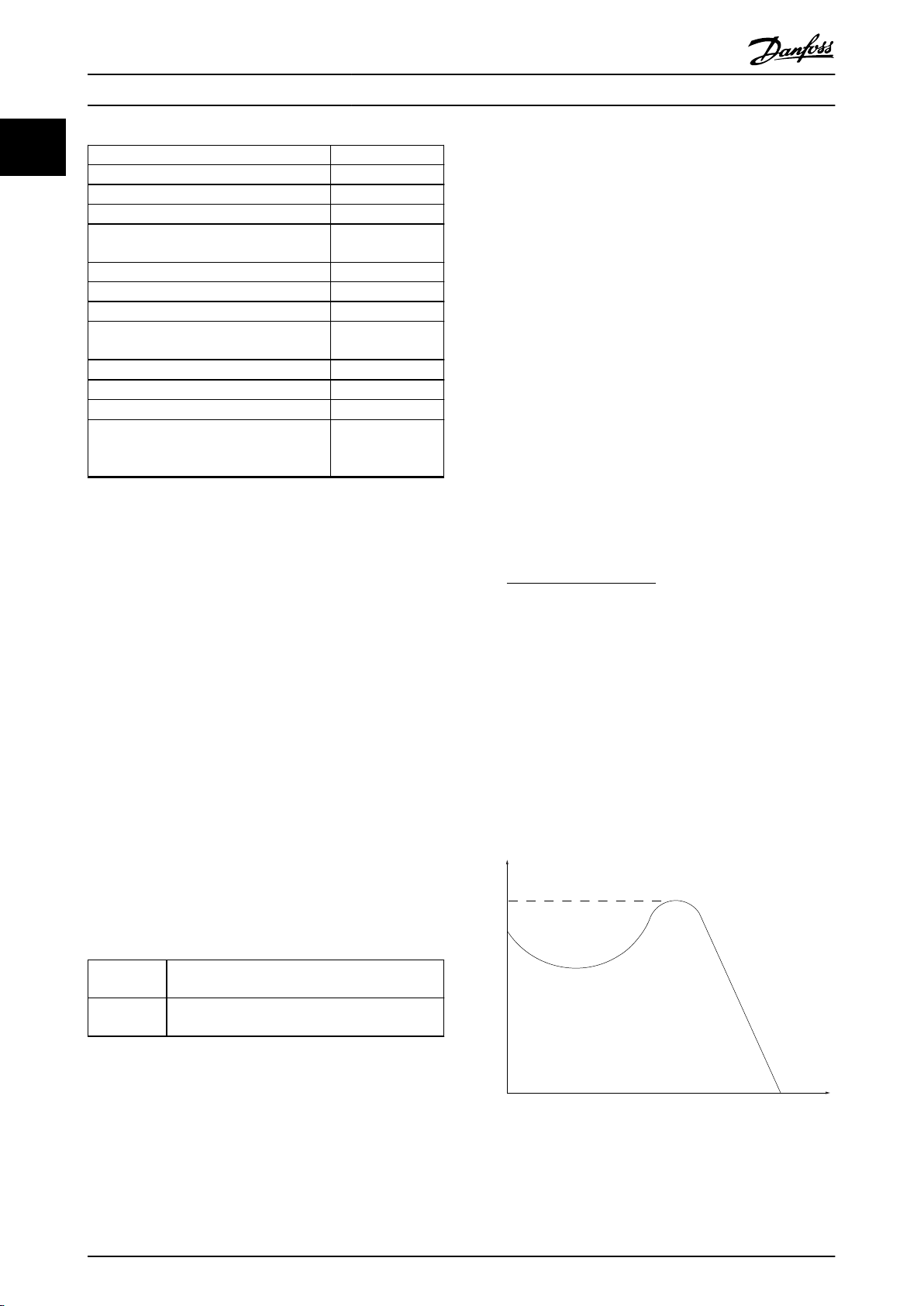
기동 토크
그룹 1 정밀 정지, 코스팅 정지, 정밀 정지 및 코스팅 정지,
급속 정지, 직류 제동, 정지, [OFF].
그룹 2 기동, 펄스 기동, 역회전 기동, 조그, 출력 고정 및
[Hand On].
표 1.1 기능 그룹
1.2.3 모터
그림 1.1 기동 토크
모터 구동 중
출력축에서 생성된 토크와 모터의 0 RPM에서 최대 속
도까지의 속도입니다.
6 Danfoss A/S © 03/2019 All rights reserved. MG06B539

소개 설계 지침서
η
VLT
AC 드라이브 효율은 입력 전원 및 출력 전원 간의 비율
로 정의됩니다.
기동 불가 명령
그룹 1의 제어 명령에 속하는 기동 불가 명령입니다. 자
표 1.1
세한 내용은
정지 명령
그룹 1의 제어 명령에 속하는 정지 명령입니다. 자세한
내용은
표 1.1
를 참조하십시오.
를 참조하십시오.
1.2.4 지령
아날로그 지령
아날로그 입력 단자 53 또는 54에 전달되는 신호이며
전압 또는 전류일 수 있습니다.
이진수 지령
직렬 통신 포트를 통해 전달되는 신호입니다.
프리셋 지령
프리셋 지령은 -100%에서 +100% 사이의 지령 범위에
서 설정할 수 있는 지령입니다. 디지털 단자를 통해 8개
의 프리셋 지령을 선택할 수 있습니다. 버스통신을 통해
4개의 프리셋 지령을 선택할 수 있습니다.
펄스 지령
디지털 입력(단자 29 또는 33)에 전달된 펄스 주파수
신호입니다.
Ref
MAX
100% 전체 범위 값(일반적으로 10 V, 20 mA)에서의
지령 입력과 결과 지령 간의 관계를 결정합니다. 최대
지령 값은
설정됩니다.
Ref
0% 값(일반적으로 0 V, 0 mA, 4 mA)에서의 지령 입력
과 결과 지령 간의 관계를 결정합니다. 최소 지령 값은
파라미터 3-02 Minimum Reference
파라미터 3-03 Maximum Reference
MIN
에서 설정됩니다.
에서
1.2.5 기타
아날로그 입력
아날로그 입력은 AC 드라이브의 각종 기능을 제어하는
데 사용합니다.
아날로그 입력에는 다음과 같은 두 가지 유형이 있습니
다.
전류 입력: 0–20 mA 및 4–20 mA.
•
전압 입력: 0–10 V DC.
•
아날로그 출력
아날로그 출력은 0–20 mA 신호 또는 4–20 mA 신호를
공급할 수 있습니다.
자동 모터 최적화, AMA
AMA 알고리즘은 정지 상태에서 연결된 모터의 전기적
인 파라미터를 결정합니다.
제동 저항
제동 저항은 회생 제동 시에 발생하는 제동 동력을 흡
수하기 위한 모듈입니다. 회생 제동 동력은 DC 링크 전
압을 증가시키고, 제동 초퍼는 이 때 발생한 동력을 제
동 저항에 전달되도록 합니다.
CT 특성
컨베이어 벨트, 배수 펌프나 크레인 등에는 일정 토크
특성이 사용됩니다.
디지털 입력
디지털 입력은 AC 드라이브의 각종 기능을 제어하는
데 사용할 수 있습니다.
디지털 출력
AC 드라이브는 24V DC(최대 40 mA) 신호를 공급할
수 있는 두 개의 고정 상태 출력을 가지고 있습니다.
ETR
Electronic Thermal Relay(전자 써멀 릴레이)의 약자
이며 실제 부하 및 시간을 기준으로 한 써멀 부하 계산
입니다. 모터 온도의 측정을 그 목적으로 합니다.
FC 표준 버스통신
FC 프로토콜이나 MC 프로토콜이 있는 RS485 버스통
신이 여기에 해당합니다.
(를) 참조하십시오.
초기화
초기화가 실행(
름 리셋)되면 AC 드라이브가 초기 설정으로 복원됩니
다.
단속적 듀티 사이클
단속적 듀티 등급은 듀티 사이클의 시퀀스를 나타냅니
다. 각각의 사이클은 부하 기간과 부하 이동 기간으로
구성되어 있습니다. 단속 부하로 운전하거나 정상 부하
로 운전할 수 있습니다.
LCP
현장 제어 패널은 AC 드라이브를 제어하고 프로그래밍
하기에 완벽한 인터페이스로 구성되어 있습니다. LCP
는 탈착식입니다. LCP는 설치 키트 옵션을 사용하여
AC 드라이브에서 최대 3미터(9.8 ft) 거리에 설치할 수
있습니다.
GLCP
그래픽 방식의 현장 제어 패널(LCP 102)은 AC 드라이
브를 제어하고 프로그래밍하기에 완벽한 인터페이스로
구성되어 있습니다. 표시창은 그래픽으로 되어 있으며
패널은 공정 값을 나타내는 데 사용됩니다. GLCP에는
저장 및 복사 기능이 있습니다.
NLCP
숫자 방식의 현장 제어 패널(LCP 21)은 AC 드라이브를
제어하고 프로그래밍하기에 완벽한 인터페이스로 구성
되어 있습니다. 표시창은 숫자로 되어 있으며 패널은 공
정 값을 나타내는 데 사용됩니다. NLCP에는 저장 및
복사 기능이 있습니다.
lsb
Least significant bit(최하위 비트)의 약자입니다.
msb
Most significant bit(최상위 비트)의 약자입니다.
파라미터 14-22 운전 모드
파라미터 8-30 프로토콜
또는 동시 누
을
1
1
MG06B539 Danfoss A/S © 03/2019 All rights reserved. 7

소개
VLT® AutomationDrive FC 360
1
MCM
미국의 케이블 단면적 측정 단위인 Mille Circular Mil
의 약자입니다. 1 MCM = 0.5067 mm2.
온라인/오프라인 파라미터
온라인 파라미터에 대한 변경 사항은 데이터 값이 변경
되면 즉시 적용됩니다. 오프라인 파라미터에 대한 변경
사항을 활성화하려면 [OK]를 누릅니다.
공정 PID
PID 제어는 변화하는 부하에 따라 출력 주파수를 자동
조정하여 속도, 압력 및 온도를 유지합니다.
PCD
Process control data(공정 제어 데이터)의 약자입니다.
전원 재투입
표시창(LCP)이 꺼질 때까지 주전원을 차단한 다음 다시
전원을 켭니다.
역률
역률은 I1과 I
역률
=
의 관계를 나타냅니다.
RMS
3xUxI1cosϕ1
3xUxI
RMS
VLT® AutomationDrive FC 360 AC 드라이브의 경우,
cosϕ1
= 1, 따라서,
역률
I1xcosϕ1
=
I
RMS
=
I
I
RMS
1
역률은 AC 드라이브가 주전원 공급에 가하는 부하의
크기입니다.
역률이 낮을수록 동일한 kW(출력)를 얻기 위해 I
RMS
가
높아집니다.
I
RMS
=
I
+ I
1
+ I
5
2
+ .. + I
7
2
n
2
2
또한 역률이 높으면 다른 고조파 전류는 낮아집니다.
내장 DC 코일은 역률을 높여 주전원 공급에 가해지는
부하를 최소화합니다.
펄스 입력/인크리멘탈 엔코더
모터 회전수에 대한 정보를 피드백하는 외부 디지털 펄
스 트랜스미터입니다. 엔코더는 정밀한 속도 제어가 요
구되는 어플리케이션에 사용됩니다.
RCD
Residual current device(잔류 전류 장치)의 약자입니
다.
셋업
2개의 셋업에 파라미터 설정을 저장할 수 있습니다. 2
개의 파라미터 셋업을 서로 변경할 수 있으며 하나의
셋업이 활성화되어 있더라도 다른 셋업을 수정할 수 있
습니다.
SFAVM
Stator Flux oriented Asynchronous Vector
Modulation(고정자속 지향성 비동기식 벡터 변조) 스위
칭 방식을 설명하는 약자입니다.
슬립 보상
AC 드라이브는 모터의 슬립 보상을 위해 모터 회전수
를 거의 일정하도록 하는 모터 부하를 측정하고 그에
따라 주파수를 보완하여 줍니다.
스마트 로직 제어(SLC)
SLC는 스마트 로직 제어기가 관련 사용자 정의 이벤트
를 TRUE(참)로 연산할 때 실행되는 사용자 정의 동작
단계입니다(파라미터 그룹
13-** 스마트 로직 제어
).
STW
상태 워드입니다.
THD
총 고조파 왜곡은 고조파 왜곡의 총 기여도를 나타냅니
다.
써미스터
온도에 따라 작동되는 저항이며, AC 드라이브 또는 모
터의 온도를 감시하는데 사용됩니다.
트립
AC 드라이브에 과전압이 발생하거나 AC 드라이브가
모터, 공정 또는 기계장치의 작동을 방해하는 경우 등
결함이 발생한 상태입니다. 결함의 원인이 사라져야 재
기동할 수 있으며 리셋을 실행하거나 또는 경우에 따라
자동으로 리셋하도록 프로그래밍하여 트립 상태를 해제
할 수 있습니다. 사용자의 안전을 위해 트립을 사용하지
마십시오.
트립 잠김
트립 잠김은 AC 드라이브에 결함이 발생하여 사용자의
개입이 필요한 상태이며 그 예로는 AC 드라이브의 출
력 단자가 단락된 경우가 있습니다. 주전원을 차단하고
결함의 원인을 제거한 다음 AC 드라이브를 다시 연결
해야만 잠긴 트립을 해제할 수 있습니다. 리셋을 실행하
거나 또는 경우에 따라 자동으로 리셋하도록 프로그래
밍하여 트립 상태를 해제해야만 재기동할 수 있습니다.
사용자의 안전을 위해 트립 잠김을 사용하지 마십시오.
VT 특성
펌프와 팬에 사용되는 가변 토크 특성입니다.
+
VVC
전압 벡터 제어(VVC+)는 표준 V/f(전압/주파수) 비율
제어에 비해 가변되는 속도 지령 및 부하토크에서 유동
성과 안정성을 향상시킵니다.
60° AVM
60° Asynchronous Vector Modulation (60° 비동기식
벡터 변조)
스위칭 방식을 의미합니다.
8 Danfoss A/S © 03/2019 All rights reserved. MG06B539
소개 설계 지침서
1.3 안전 주의사항
경고
주전원이 연결되어 있는 경우 AC 드라이브의 전압은
항상 위험합니다. 모터, AC 드라이브 또는 필드버스가
올바르게 설치되지 않으면 사망, 심각한 신체 상해 또는
장비 손상의 원인이 될 수 있습니다. 따라서, 이 설명서
의 내용 뿐만 아니라 국내 또는 국제 안전 관련 규정을
반드시 준수해야 합니다.
하지 않습니다. 이러한 경우, 주전원 공급을 차
단합니다.
4. 드물기는 하지만 AC 드라이브에서의 제어 신
호 또는 내부의 제어 신호가 잘못 활성화되거
나 지연되거나 전체적으로 결함이 발생할 수
있습니다. 안전이 최우선인 상황에서 사용되는
경우(예를 들어, 호이스트 어플리케이션의 전자
기식 제동 기능을 제어하는 경우), 이러한 제어
신호에 전적으로 의존해서는 안 됩니다.
1
1
안전 규정
1. 수리 작업을 수행하기 전에는 항상 AC 드라이
브에 연결된 주전원 공급을 차단합니다. 모터
와 주전원 공급을 분리하기 전에 주전원 공급
이 차단되었는지 확인하고
전 시간을 준수합니다.
2. LCP의 [Off/Reset]으로는 주전원 공급을 차단
할 수 없으며 안전 스위치로 사용해서는 안 됩
니다.
3. 관련 국제 및 국내 규정에 의거, 장비를 올바르
게 접지하고 공급 전압으로부터 사용자를 보호
하며 과부하로부터 모터를 보호합니다.
4. 모터 과부하 보호 기능은 공장 설정값에 포함
되어 있지 않습니다. 이 기능이 필요하면
미터 1-90 모터 열 보호을 [4] ETR 트립 1
또는
[3] ETR 경고 1
5. 부하 공유(DC 매개 회로의 링크)가 있는 경우,
AC 드라이브에는 L1, L2, L3 이상의 전압 소
스가 있다는 점에 유의하시기 바랍니다. 수리
작업을 수행하기 전에 모든 전압 소스가 차단
되었는지 또한 충분히 시간이 경과했는지 확인
합니다.
의도하지 않은 기동에 대한 경고
1. AC 드라이브가 주전원에 연결되어 있는 동안
에는 디지털 명령, 버스통신 명령, 지령 또는
현장 정지로 모터가 정지될 수 있습니다. 의도
하지 않은 기동이 발생하지 않도록 하는 등 신
체 안전(예를 들어, 의도하지 않은 기동 후 가
동부 접촉에 의한 신체 상해 위험)을 많이 고려
하는 경우에는 이와 같은 정지 기능으로도 부
족합니다. 이러한 경우, 주전원 공급을 차단합
니다.
2. 파라미터를 설정하는 동안 모터가 기동할 수도
있습니다. 만일 이러한 상황이 신체 안전에 해
가 될 수 있는 경우, 예를 들어, 모터 연결을
차단하여 모터 기동을 막아야 합니다.
3. 일시적인 과부하가 발생하거나 전원 공급 전력
망에 결함이 발생하거나 모터 연결이 끊어져
AC 드라이브의 전자부품에 결함이 발생한 경
우에는 주전원 공급이 연결된 상태에서 정지된
모터가 기동할 수 있습니다. 신체 안전상의 이
유로 의도하지 않은 기동을 막아야 하는 경우,
AC 드라이브의 정상 정지 기능만으로는 충분
표 1.2
에 명시된 방
로 설정합니다.
파라
경고
고전압
주전원으로부터 장비를 차단한 후에라도 절대로 전자부
품을 만지지 마십시오. 치명적일 수 있습니다.
부하 공유(DC 매개 회로의 링크)뿐만 아니라 회생동력
백업을 위한 모터 연결을 포함하여 모든 전압 입력이
차단되었는지 확인합니다.
AC 드라이브가 설치된 시스템에는 필요한 경우 기계
공구 관련 법규, 사고 예방 관련 규정 등과 같은 유효한
안전 규정에 따라 감시 및 보호 장치를 추가로 장착해
야 합니다. 운전 소프트웨어를 통한 AC 드라이브 개조
는 허용됩니다.
주의 사항
필요한 예방 수단을 고려할 책임이 있는 기계 제조업체/
설치업체에 의해 위험한 상황이 파악되어야 합니다. 추
가적인 감시 및 보호 장치가 포함될 수 있으며 이러한
장치를 추가할 때는 반드시 기계 공구 관련 법규, 사고
예방 관련 규정과 같은 유효한 안전 규정에 따라 장착
해야 합니다.
경고
방전 시간
AC 드라이브에는 AC 드라이브에 전원이 인가되지 않
더라도 충전이 유지될 수 있는 DC 링크 컨덴서가 포함
되어 있습니다. 경고 LED 표시등이 꺼져 있더라도 고전
압이 남아 있을 수 있습니다. 전원을 분리한 후 서비스
또는 수리 작업을 진행하기 전까지 지정된 시간 동안
기다리지 않으면 사망 또는 중상으로 이어질 수 있습니
다.
모터를 정지합니다.
•
교류 주전원 및 원격 DC 링크 전원 공급(배터
•
리 백업장치, UPS 및 다른 AC 드라이브에 연
결된 DC 링크 연결장치 포함)을 차단합니다.
PM 모터를 차단하거나 구속시킵니다.
•
컨덴서가 완전히 방전될 때까지 기다립니다.
•
최소 대기 시간은
AC 드라이브 상단의 제품 라벨에서도 확인할
수 있습니다.
서비스 또는 수리 작업을 수행하기 전에 적절
•
한 전압 측정 장치를 사용하여 컨덴서가 완전
히 방전되었는지 확인합니다.
표 1.2
에 명시되어 있으며
MG06B539 Danfoss A/S © 03/2019 All rights reserved. 9
소개
VLT® AutomationDrive FC 360
1
전압
[V]
380–480
380–480
표 1.2 방전 시간
폐기물 처리 지침
1.4
출력 범위
[kW (hp)]
0.37–7.5 kW
(0.5–10 hp)
11–75 kW
(15–100 hp)
전기 부품이 포함된 장비를 일반 생활 폐기물
과 함께 처리해서는 안 됩니다.
해당 지역 법규 및 최신 법규에 따라 전기 및
전자장비 폐기물과 함께 분리 처리해야 합니
다.
최소 대기 시간
(분)
4
15
1.5 문서 및 소프트웨어 버전
본 설명서는 정기적으로 검토 및 업데이트됩니다. 개선
관련 제안은 언제든지 환영합니다.
버전 비고 소프트웨어 버전
MG06B5xx 신규 하드웨어 및 소프트
웨어 출시로 인한 업데이
트.
1.8x
1.6 승인 및 인증
주파수 변환기는 이 절에 설명된 규정을 준수하도록 설
계되어 있습니다.
1.6.2 저전압 지침
드라이브는 전자 구성품으로 분류되며 저전압 지침에
따라 CE 라벨 인증을 획득해야 합니다. 이 지침은 50–
1000 V AC 및 75–1500 V DC 전압 범위의 모든 전기
장비에 적용됩니다.
이 지침은 장비 설계 시 인간과 가축의 안전과 건강을
보장하고 장비를 올바르게 설치, 유지보수 및 용도에 맞
게 사용하여 재료가 그대로 보존되도록 규정하고 있습
니다. 댄포스 CE 라벨은 저전압 지침을 준수하며 댄포
스는 요청 시 적합성 선언을 제공합니다.
1.6.3 EMC 규정
전자기 호환성(EMC)는 개별 장비 간의 전자기적 간섭
이 해당 장비의 성능을 저해하지 않음을 의미합니다.
EMC 규정 2014/30/EU의 기본 보호 요구사항에 따르
면 전자기 간섭(EMI)을 유발하거나 EMI에 의해 그 작
동이 영향을 받을 수 있는 장치는 전자기 간섭의 유발
을 제한하도록 설계되어야 하며 올바르게 설치, 유지보
수 및 용도에 맞게 사용할 경우 적절한 EMI 내성 레벨
을 갖춰야 합니다.
드라이브는 독립형 장치로 사용할 수도 있고 보다 복잡
한 설비의 일부로 사용할 수도 있습니다. 두 가지 경우
모두 장치에 대한 CE 마크 인증을 고려해야 합니다. 시
스템이 반드시 CE 마크 인증을 획득할 필요는 없지만
EMC 규정의 기본 보호 요구사항은 반드시 준수해야 합
니다.
승인 및 인증서에 관한 자세한 정보를 확인하려면 다음
웹사이트의 다운로드 영역으로 이동합니다.
www.danfoss.com/fc360
.
1.6.1 CE 마크
CE 마크(Conformité Européenne)는 해당 제품 제조업
체가 모든 관련 EU 규정을 준수함을 의미합니다.
드라이브의 설계 및 제조에 적용 가능한 EU 규정은 다
음과 같습니다.
저전압 지침.
•
EMC 규정.
•
기계류 지침(통합형 안전 기능이 있는 유닛에
•
해당).
CE 마크는 ECU 내 EC 국가들과 EFTA 국가들 간의
자유 무역 기술 장벽을 제거하기 위한 용도입니다. CE
마크는 제품의 품질을 규제하지 않습니다. CE 마크에서
기술 사양을 추론해 낼 수는 없습니다.
10 Danfoss A/S © 03/2019 All rights reserved. MG06B539
130BA870.10
130BA809.10
130BA810.10
130BA810.10
130BA810.10
130BA826.10
130BA826.10
제품 개요 설계 지침서
2 제품 개요
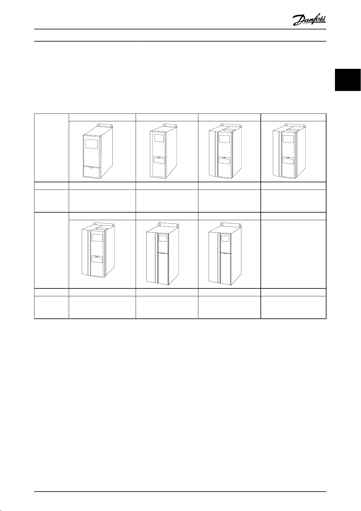
2.1 외함 용량 개요
외함 용량은 전력 범위에 따라 다릅니다.
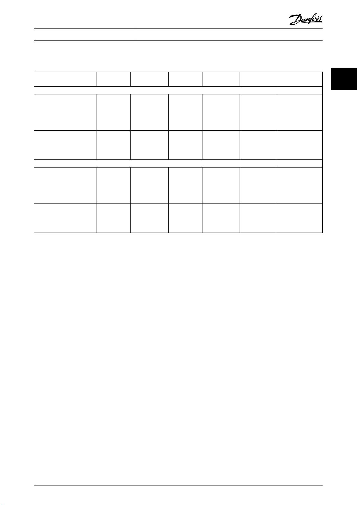
외함 용량 J1 J2 J3 J4
외함 보호 IP20 IP20 IP20 IP20
높은 과부하 정
격 동력 - 최대
160% 과부하
외함 용량 J5 J6 J7
0.37–2.2 kW/0.5–3 hp
1)
(380–480 V)
3.0–5.5 kW/4.0–7.5 hp
(380–480 V)
7.5 kW/10 hp (380–480 V)
11–15 kW/15–20 hp
(380–480 V)
2 2
외함 보호 IP20 IP20 IP20
높은 과부하 정
격 동력 - 최대
160% 과부하
18.5–22 kW/25–30 hp
1)
(380–480 V)
30–45 kW/40–60 hp
(380–480 V)
55–75 kW/75–100 hp
(380–480 V)
표 2.1 외함 용량
1) 용량 11–75 kW (15–100 hp) 정상 과부하 유형: 110% 과부하 1분.
용량 0.37–7.5 kW (0.5–10 hp) 높은 과부하 유형: 160% 과부하 1분.
용량 11–22 kW (15–30 hp) 높은 과부하 유형: 150% 과부하 1분.
용량 30–75 kW (40–100 hp) 높은 과부하 유형: 150% 과부하 1분.
MG06B539 Danfoss A/S © 03/2019 All rights reserved. 11
130BC438.19
3 phase
power
input
Switch mode
power supply
Motor
Interface
(PNP) = Source
(NPN) = Sink
ON=Terminated
OFF=Open
Brake
resistor
91 (L1)
92 (L2)
93 (L3)
PE
50 (+10 V OUT)
53 (A IN)
54 (A IN)
55 (COM A IN/OUT)
0/4-20 mA
12 (+24 V OUT)
33 (D IN)
18 (D IN)
20 (COM D IN)
10 V DC
15 mA 100 mA
+ - + -
(U) 96
(V) 97
(W) 98
(PE) 99
(P RS485) 68
(N RS485) 69
(COM RS485) 61
0V
5V
S801
RS485
RS485
03
+10 V DC
0/4-20 mA
0-10 V DC
24 V DC
02
01
05
04
250 V AC, 3 A
24 V (NPN)
0 V (PNP)
0 V (PNP)
24 V (NPN)
19 (D IN)
24 V (NPN)
0 V (PNP)
27 (D IN/OUT)
24 V
0 V
0 V (PNP)
24 V (NPN)
0 V
24 V
29 (D IN/OUT)
24 V (NPN)
0 V (PNP)
0 V (PNP)
24 V (NPN)
32 (D IN)
31 (D IN)
95
P 5-00
21
ON
(+UDC) 89
(BR) 81 5)
24 V (NPN)
0 V (PNP)
0-10 V DC
(-UDC) 88
RFI
3)
0 V
250 V AC, 3 A
Relay 1
1)
Relay 2 2)
4)
06
42 (A OUT)
45 (A OUT)
Analog
output
0/4-20 mA
제품 개요
VLT® AutomationDrive FC 360
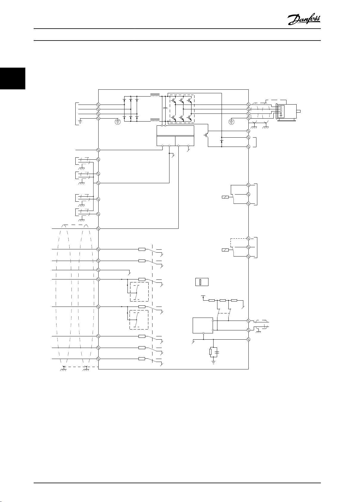
2.2 전기적인 설치
이 절에서는 AC 드라이브 배선 방법을 설명합니다.
22
그림 2.1 기본 배선 구조
A=아날로그, D=디지털
1) J1–J5에 한해서 내장 제동 초퍼를 사용할 수 있습니다.
2) 릴레이 2는 J1–J3의 경우 2극이며 J4–J7의 경우 3극입니다. 단자 4, 5 및 6이 있는 J4–J7의 릴레이 2는 NO/NC
논리가 릴레이 1과 동일합니다. 릴레이는 J1–J5의 경우 플러그형이며 J6–J7의 경우 고정형입니다.
3) J1–J5 기준 단일 DC 초크, J6–J7 기준 듀얼 DC 초크.
4) S801 스위치(버스통신 단자)는 RS485 포트(단자 68 및 69)를 종단하는데 사용할 수 있습니다.
5) J6–J7의 경우, BR 없음.
12 Danfoss A/S © 03/2019 All rights reserved. MG06B539
e30bf228.11
L1
L2
L3
PE
PE
u
v
w
2
1
3
5
16
17
18
14
12
8
7
10
9
4
11
13
4
6
15
90
4
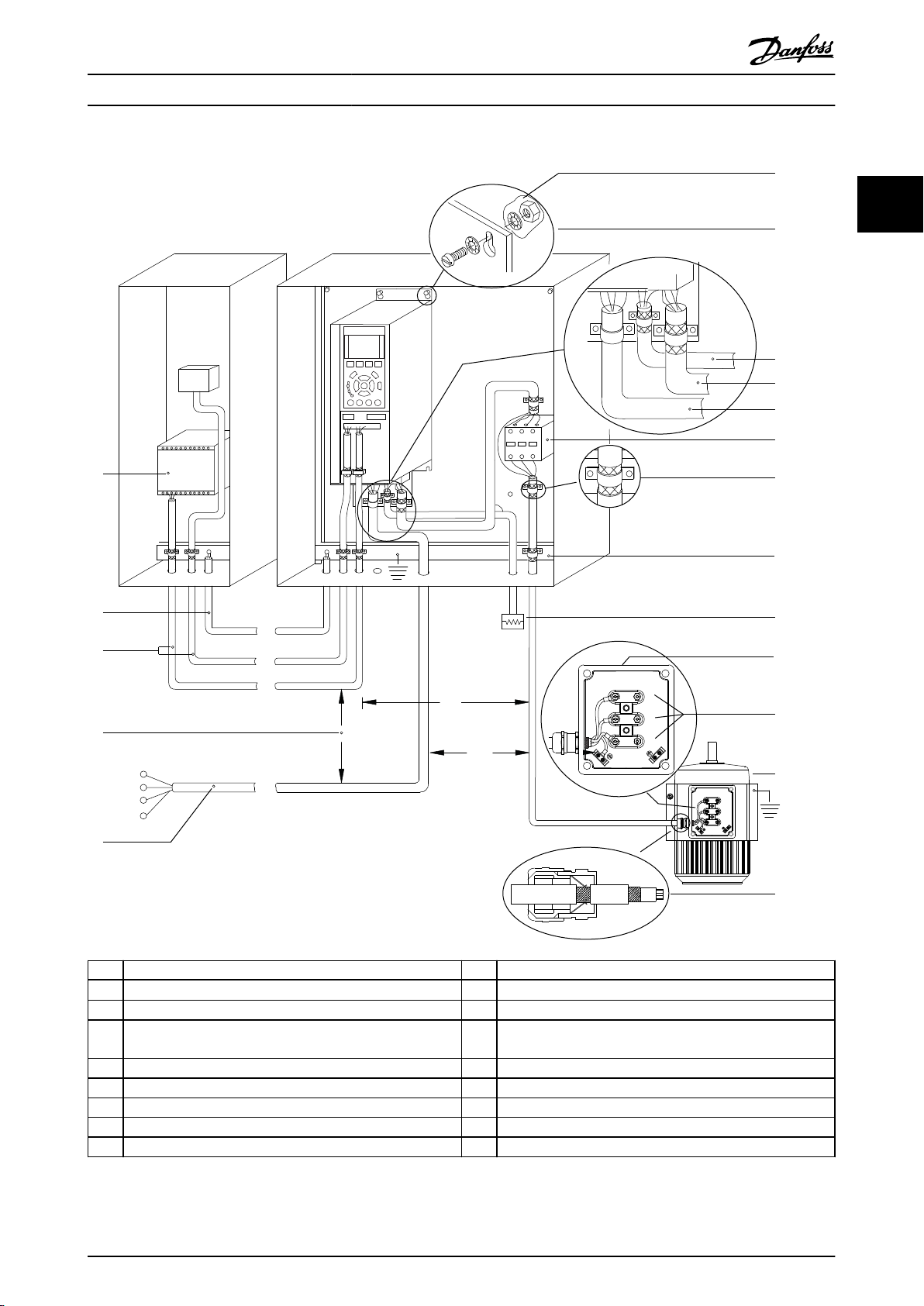
제품 개요 설계 지침서
2 2
1 PLC 10 주전원 케이블(비차폐)
2
최소 16 mm2 (6 AWG)의 등화 케이블
3 제어 케이블 12 절연 피복 벗긴 케이블
4 제어 케이블, 모터 케이블 및 주전원 케이블 간 최소 200 mm
(7.87인치)
5 주전원 공급 14 제동 저항
6 기본(비착색) 표면 15 금속 박스
7 스타 와셔 16 모터 연결부
8 제동 케이블(차폐) 17 모터
9 모터 케이블(차폐) 18 EMC 케이블 글랜드
그림 2.2 일반적인 전기 연결
11 출력 콘택터 등
13 공통 접지 버스바. 캐비닛 접지는 국내 및 국제 요구사항을 준수
합니다.
MG06B539 Danfoss A/S © 03/2019 All rights reserved. 13

130BC500.10
FC 1
FC 1
FC 2
FC 2
FC 3
FC 3
PE
PE
제품 개요
경고
장비 위험
22
회전축 및 전기 장비는 위험할 수 있습니다. 유닛에 전
원을 공급할 때는 전기적인 위험이 노출되지 않도록 보
호하는 것이 중요합니다. 전기 작업 시에는 항상 국제
및 국내 전기 규정을 준수해야 합니다. 설치, 기동 및
유지보수는 반드시 교육을 받은 공인 기사만 수행해야
합니다. 이러한 지침을 준수하지 못하면 사망 또는 중상
으로 이어질 수 있습니다.
경고
배선 절연
고주파 노이즈 절연을 위해 3개의 별도 금속 도관을 배
치하거나 별도의 차폐 케이블을 사용하여 입력 전원, 모
터 배선 및 제어 배선을 분리합니다. 전원, 모터 및 제
어 배선을 적절히 분리하지 못하면 AC 드라이브 및 관
련 장비가 최적의 성능을 발휘하지 못할 수 있습니다.
여러 대의 AC 드라이브에 있는 모터 케이블을 각각 따
로 배치합니다. 나란히 배열된 출력 모터 케이블의 유도
전압은 장비가 꺼져 있거나 잠겨 있어도 컨덴서를 충전
할 수 있습니다. 출력 모터 케이블을 별도로 분리하여
배선하지 않거나 차폐 케이블을 사용하지 않으면 사망
또는 중상으로 이어질 수 있습니다.
VLT® AutomationDrive FC 360
3.5mA 이상의 접지 전류에 대응할 수 있도록
•
장비를 올바르게 보호 접지합니다. 자세한 내
용은
입력 전원, 모터 출력 및 제어 배선에는 각기
•
다른 접지 와이어가 필요합니다.
올바른 접지 연결을 위해 장비와 함께 제공된
•
클램프를 사용합니다.
하나의 AC 드라이브를 다른 AC 드라이브에
•
"데이지 체인(연쇄)" 방식으로 접지하지 마십시
오(
접지 와이어를 가능한 짧게 연결합니다.
•
고-스트랜드 와이어를 사용하여 전기 노이즈를
•
줄입니다.
모터 제조업체 배선 요구사항을 준수합니다.
•
장을 2.8 접지 누설 전류
그림 2.3
참조).
을 참조하십시오.
출력 모터 케이블을 분리 설치합니다.
•
차폐 케이블을 사용합니다.
•
모든 AC 드라이브를 동시에 잠급니다.
•
와이어 유형 및 등급
모든 배선은 단면적 및 주위 온도 요구사항과
•
관련하여 지역 및 국가 규정을 준수해야 합니
다.
댄포스는 모든 전원 연결부가 최소 75 °C
•
(167 °F) 정격의 구리 와이어로 되어 있기를
권장합니다.
권장 와이어 규격은
•
오.
장을 4 사양
2.2.1 접지 요구사항
경고
접지 위험!
작업자의 안전을 위해 공인 전기 설치업자가 이 설명서
에 수록된 지침 뿐만 아니라 국제 및 국내 전기 규정을
준수하여 AC 드라이브를 올바르게 접지해야 합니다. 접
지 전류는 3.5mA보다 높습니다. AC 드라이브를 올바르
게 접지하지 못하면 사망 또는 중상으로 이어질 수 있
습니다.
을 참조하십시
그림 2.3 접지 원칙
경고
유도 전압
여러 대의 AC 드라이브에 있는 출력 모터 케이블을 각
각 배치합니다. 나란히 배열된 출력 모터 케이블의 유도
전압은 장비가 꺼져 있거나 잠겨 있어도 컨덴서를 충전
할 수 있습니다. 출력 모터 케이블을 적절히 분리하지
못할 경우 사망 또는 중상으로 이어질 수 있습니다.
모터 배선을 위해 접지 클램프가 제공됩니다(
참조).
그림 2.4
14 Danfoss A/S © 03/2019 All rights reserved. MG06B539
130BC501.10
01
02 03
04
05
130BD648.11
제품 개요 설계 지침서
AC 드라이브와 모터 사이에 역률 보정 컨덴서
•
를 설치하지 마십시오.
AC 드라이브와 모터 사이에 기동 또는 극 전
•
환 장치를 배선하지 마십시오.
모터 제조업체 배선 요구사항을 준수합니다.
•
모든 AC 드라이브는 1상 접지 전원과 비접지
•
입력 전원에서 사용할 수 있습니다. 절연된 주
전원 소스(IT 주전원, 또는 비접지 델타) 또는
접지된 레그가 있는 TT/TN-S 주전원(접지형
델타)에서 전원이 공급되는 경우,
터 14-50 RFI 필터
량 J6–J7)하거나 RFI 나사를 제거(외함 용량
J1–J5)합니다. 꺼짐(OFF) 상태에서 중간 회로
의 손상을 방지하고 IEC 61800-3에 따라 접
지 용량형 전류를 줄이기 위해 섀시와 중간 회
로 간의 내부 RFI 필터 컨덴서가 차단됩니다.
AC 드라이브와 IT 주전원의 모터 사이에 스위
•
치를 설치하지 마십시오.
를 꺼짐으로 설정(외함 용
파라미
2 2
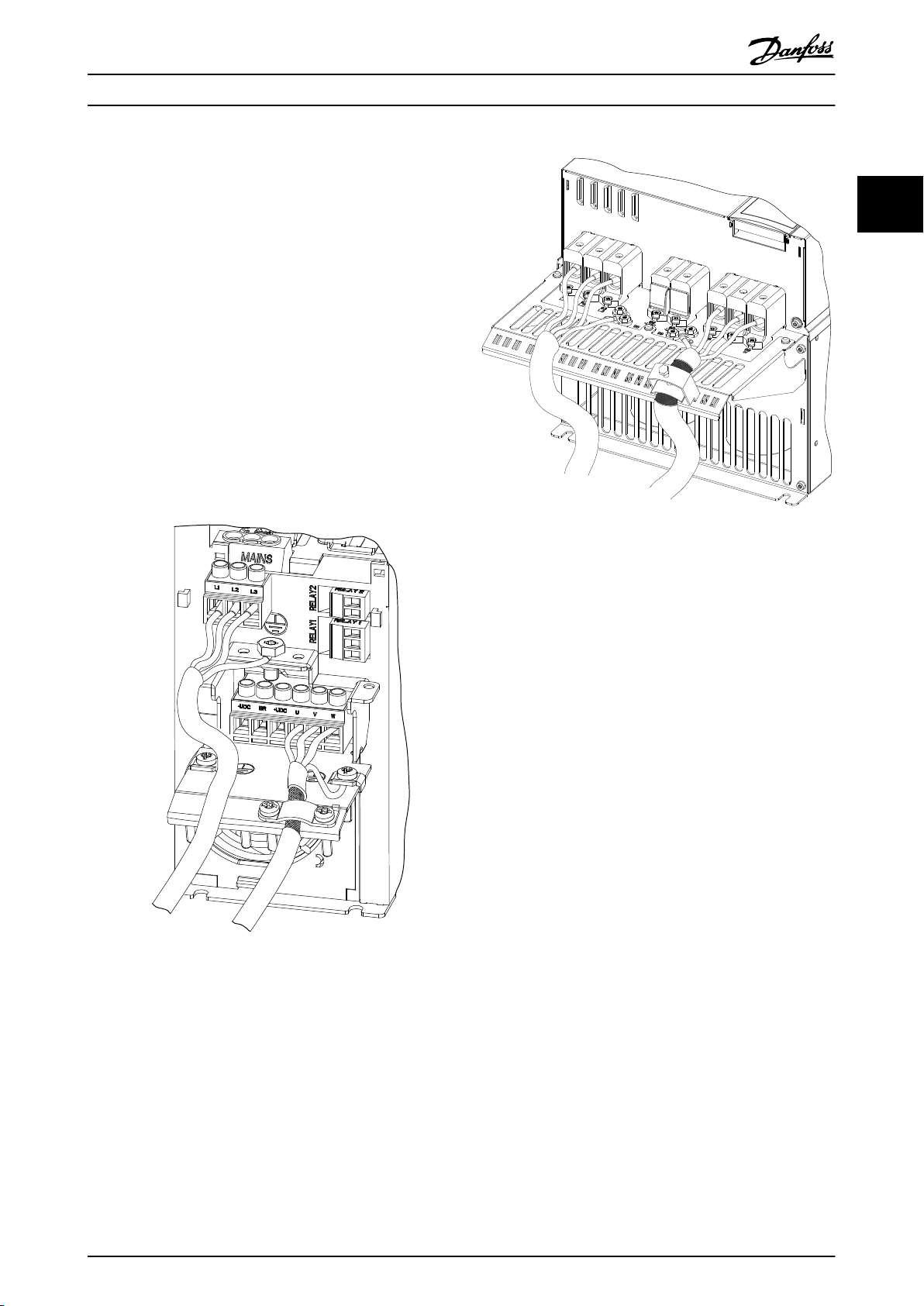
그림 2.5 외함 용량 J6–J7의 주전원, 모터 및 접지 연결(예시
J7)
그림 2.4 외함 용량 J1–J5의 주전원, 모터 및 접지 연결(예시
J2)
그림 2.4
지를 나타냅니다.
입력, 모터 및 접지를 나타냅니다. 실제 구성은 유닛 유
형 및 옵션 장비에 따라 다릅니다.
은 외함 용량 J1–J5의 주전원 입력, 모터 및 접
그림 2.5
은 외함 용량 J6–J7의 주전원
MG06B539 Danfoss A/S © 03/2019 All rights reserved. 15
130BC504.11
42 45
12
18
19
27
29
31
32
33
20
50
53
54
55
130BC505.12
제품 개요
VLT® AutomationDrive FC 360
2.2.2 제어 배선
접근
22
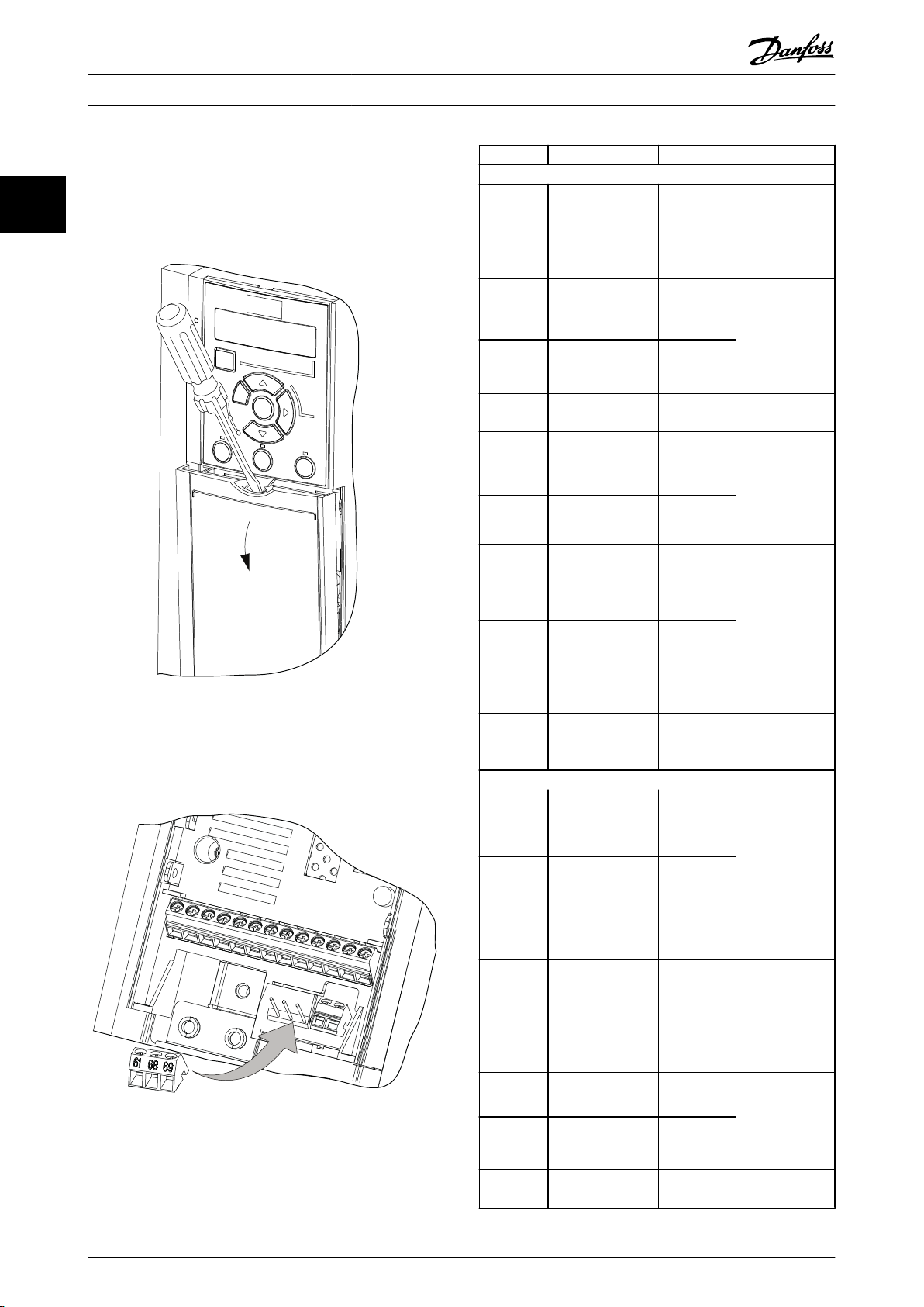
그림 2.6 외함 용량 J1–J7의 제어 배선 접근
제어 단자 유형
그림 2.7
기능 및 초기 설정은
그림 2.7 제어 단자 위치
단자 등급 세부 내용은
시오.
스크류드라이버로 덮개 플레이트를 분리합니
•
다.
그림 2.6
을(를) 참조하십시오.
는 AC 드라이브 제어 단자를 나타냅니다. 단자
표 2.2
에 요약되어 있습니다.
장을 4.2 일반사양
를 참조하십
단자 파라미터 초기 설정 설명
디지털 I/O, 펄스 I/O, 엔코더
24V DC 공급 전
압. 최대 출력 전
12 – +24 V DC
파라미터 5-10 단자
18
파라미터 5-11 단자
19
파라미터 5-16 단자
31
파라미터 5-14 단자
32
파라미터 5-15 단자
33
파라미터 5-12 단자
27
파라미터 5-30 단자
파라미터 5-13 단자
29
파라미터 5-31 단자
18 디지털 입력
19 디지털 입력
X30/2 디지털 입력
32 디지털 입력
33 디지털 입력
27 디지털 입력
27 디지털 출력
29 디지털 입력
[8] 기동
[10] 역회전
[0] 운전하지
않음
[0] 운전하지
않음
[0] 운전하지
않음
DI [2] 코스
팅 인버스
DO [0] 운전
하지 않음
DI [14] 조그
DO [0] 운전
하지 않음
29디지털출력
디지털 입력용 공
20 –
아날로그 입력/출력
파라미
42
터 6-91 Terminal
42 Analog Output
파라미
45
터 6-71 Terminal
45 Analog Output
50 – +10 V DC
53 6-1* 파라미터 그룹 지령
54 6-2* 파라미터 그룹 피드백
55 –
[0] 운전하지
않음
[0] 운전하지
않음
류는 모든 24V 부
하에 대해 100mA
입니다.
디지털 입력.
디지털 입력
디지털 입력, 24
V 엔코더. 단자
33은 펄스 입력에
사용할 수 있습니
다.
디지털 입력, 디지
털 출력 또는 펄스
출력에 대해 선택
할 수 있습니다.
초기 설정은 디지
털 입력입니다.
단자 29는 펄스
입력에 사용할 수
있습니다.
통 및 24V 공급에
대한 0V.
프로그래밍 가능
한 아날로그 출력.
아날로그 신호는
최대 500 Ω에서
0-20mA 또는
4-20mA입니다.
또한 디지털 출력
으로도 구성할 수
있습니다.
10V DC 아날로그
공급 전압. 최대
15mA가 가변 저
항기 또는 써미스
터에 공통으로 사
용됩니다.
아날로그 입력. 전
압 또는 전류에 대
해 선택할 수 있습
니다.
아날로그 입력용
공통
16 Danfoss A/S © 03/2019 All rights reserved. MG06B539
1
2
PE
FC
PE
PLC
130BB922.12
PE PE
<10 mm
100nF
FC
PE
PE
PLC
<10 mm
130BB609.12
PE
FC
PE
FC
130BB923.12
PE PE
69
68
61
69
68
61
1
2
<10 mm
PE
FC
PE
FC
130BB924.12
PE PE
69
69
68
68
1
2
<10 mm
제품 개요 설계 지침서
단자 파라미터 초기 설정 설명
직렬 통신
차폐를 위한 통합
형 RC 필터. EMC
61 –
68 (+) 8-3* 파라미터 그룹
69 (-) 8-3* 파라미터 그룹
문제가 있을 때 차
폐를 연결하는 용
도로만 사용.
RS485 인터페이
스. 종단 처리를
할 수 있도록 제어
카드에 스위치가
제공됩니다.
1
최소 16 mm2 (6 AWG)
2 등화 케이블
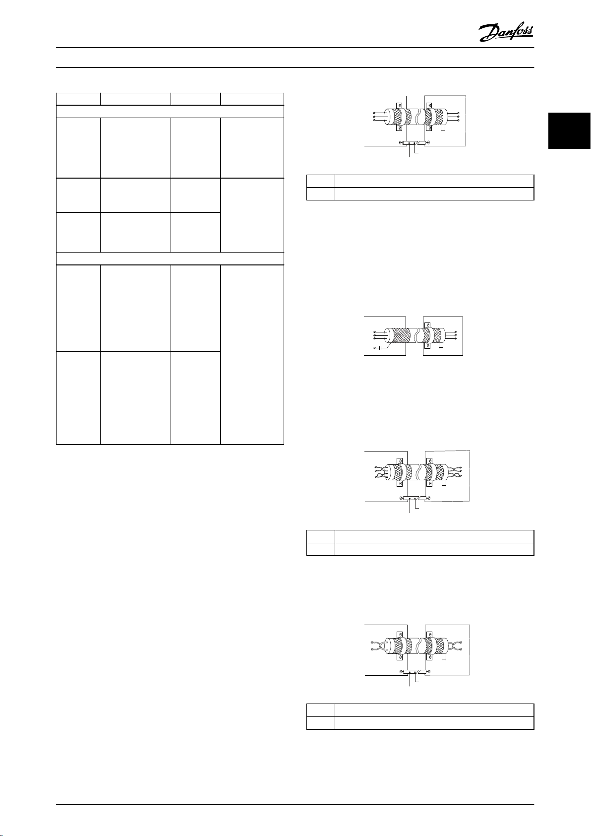
그림 2.8 양쪽 끝의 차폐 클램프
2 2
50/60Hz 접지 루프
매우 긴 제어 케이블을 사용하면 접지 루프가 발생할
수 있습니다. 접지 루프를 없애려면 차폐-접지선의 한
쪽 끝과 100 nF 컨덴서를 연결합니다. 이 때, 리드선을
가능한 짧게 합니다.
그림 2.9 100 nF 컨덴서 연결
직렬 통신에 EMC 노이즈가 생기지 않게 하는 방법
이 단자는 내부 RC 링크를 통해 접지에 연결됩니다. 꼬
여 있는 케이블을 사용하여 도체 간의 간섭을 줄입니다.
권장 방법은
그림 2.10
에서 보는 바와 같습니다.
01, 02, 03 5-40 [0]
04, 05, 06 5-40 [1]
릴레이
[0] 운전하지
않음
[0] 운전하지
않음
C형 릴레이 출력.
이러한 릴레이는
AC 드라이브 구성
및 용량에 따라 다
양한 위치에 배치
됩니다. 교류 또는
DC 전압, 저항 부
하 또는 유도 부하
에 사용할 수 있습
니다.
J1-J3 외함의
RO2는 2극이며
단자 04와 05만
사용할 수 있습니
다.
표 2.2 단자 설명
제어 단자 기능
제어 입력 신호를 수신함으로써 AC 드라이브 기능이
명령됩니다.
각 단자를 해당 단자와 관련된 파라미터에서
•
지원하는 기능에 맞게 프로그래밍합니다.
제어 단자가 올바른 기능에 맞게 프로그래밍되
•
1
최소 16 mm2 (6 AWG)
2 등화 케이블
어 있는지 확인합니다. 파라미터 접근 및 프로
그래밍에 관한 자세한 내용은 요약 지침서의
현장 제어 패널 및 프로그래밍
장을 참조하십
그림 2.10 꼬여 있는 케이블
시오.
초기 단자 프로그래밍은 일반적인 운전 모드에
•
혹은 단자 61 연결을 생략할 수 있습니다.
서 AC 드라이브의 기능을 사용할 수 있게 합
니다.
차폐 제어 케이블 사용
대부분의 경우, 선호하는 방법은 제공된 차폐 클램프로
제어 및 직렬 통신 케이블의 양쪽 끝을 고정하여 최적
의 높은 주파수 대역의 케이블 연결이 되도록 하는 것
입니다.
AC 드라이브와 PLC 간의 접지 전위가 다를 경우에는
전기적 노이즈가 발생하여 전체 시스템에 문제가 발생
1
최소 16 mm2 (6 AWG)
2 등화 케이블
할 수 있습니다. 이럴 경우 등화 케이블을 제어 케이블
에 최대한 가깝게 연결하여 이 문제를 해결합니다. 이
그림 2.11 단자 61 연결 없는 꼬여 있는 케이블
때, 등전위 케이블의 최소 단면적은 16 mm2 (6 AWG)
입니다.
MG06B539 Danfoss A/S © 03/2019 All rights reserved. 17

제품 개요
VLT® AutomationDrive FC 360
2.3 제어 구조
2.3.1 제어 방식
22
AC 드라이브는 주전원으로부터의 교류 전압을 정류하
여 DC 전압으로 변환합니다. 그리고 나서 이 DC 전압
을 가변 진폭과 주파수를 가진 교류 전류로 변환합니다.
이로 인해 모터 측에 가변 전압/전류와 가변 주파수를
공급할 수 있어 3상 표준형 교류 모터와 PM 동기식 모
터의 무한 가변 속도 제어가 가능합니다.
속도/토크 지령
이러한 제어에 대한 지령은 단일 지령이거나 상대적으
로 다르게 범위가 설정된 지령을 포함한 여러 지령의
합일 수 있습니다. 지령 처리는
자세히 설명되어 있습니다.
장을 2.4 지령 처리
에
2.3.2 제어 모드
AC 드라이브는 모터축의 속도 또는 토크를 제어할 수
있습니다.
형태를 결정합니다.
속도 제어
속도 제어는 다음과 같은 두 가지 형태로 이루어집니다.
파라미터 7-00 속도 PID 피드백 소스
드백으로 사용할 입력을 선택합니다.
토크 제어
토크 제어 기능은 모터 출력 축의 토크가 인장 제어로
서 어플리케이션을 제어하고 있는 어플리케이션에 사용
됩니다.
택할 수 있습니다. 아날로그, 디지털 또는 버스통신 제
어 지령을 설정하면 토크가 설정됩니다. 토크 제어를 구
동할 때는 올바른 모터 데이터가 최적 성능 달성에 중
요하므로 완전 AMA 절차의 실행을 권장합니다.
파라미터 1-00 구성 모드
속도 개회로 제어로, 모터로부터의 피드백이
•
필요 없습니다(센서리스).
속도 폐회로 PID 제어로, 입력으로의 속도 피
•
드백이 필요합니다. 최적화된 폐회로 속도 제
어를 사용하면 개회로 속도 제어를 사용할 때
에 비해 정밀도가 높아집니다.
파라미터 1-00 구성 모드
VVC+모드의 폐회로. 이 기능은 축의 동적 변
•
화가 낮은 수준에서 중간 수준인 어플리케이션
에 사용되며 모든 사분면과 모든 모터 회전수
에서 탁월한 성능을 제공합니다. 속도 피드백
신호는 필수입니다. MCB102 옵션 카드의 사
용을 권장합니다. 속도 피드백 신호의 정밀도
가 중요하므로 엔코더 분해능은 최소 1024
PPR이어야 하고 엔코더의 차폐 케이블은 제대
로 접지되어 있어야 합니다. 최상의 속도 피드
백 신호를 얻을 수 있도록
도 PID 저주파 통과 필터 시간
VVC+ 모드의 개회로. 이 기능은 기계적으로
•
견고한 어플리케이션에 사용되지만 그 정밀도
는 제한적입니다. 개회로 토크 기능은 두 방향
모두에서 작동합니다. 토크는 AC 드라이브의
내부 전류 측정을 기준으로 계산됩니다.
을 설정하여 제어
에서 속도 PID 피
에서 토크 제어를 선
파라미터 7-06 속
를 튜닝합니다.
18 Danfoss A/S © 03/2019 All rights reserved. MG06B539

130BD974.10
L2 92
L1 91
L3 93
M
U 96
V 97
W 98
RFI switch
Inrush
R+
82
Load sharing -
88(-)
R81
Brake resistor
Load sharing +
89(+)
Load sharing -
Load sharing +
L2 92
L1 91
L3 93
89(+)
88(-)
Inrush
R inr
M
U 96
V 97
W 98
P 14-50
130BD975.10
제품 개요 설계 지침서
2.3.3 FC 360 제어 방식
VLT® AutomationDrive FC 360는 가변 속도 어플리케이션에 일반적으로 사용되는 AC 드라이브입니다. 제어 방식
은 전압 벡터 제어+를 기준으로 합니다.
0.37–22 kW (0.5–30 hp)
FC 360 0.37–22 kW (0.5–30 hp) AC 드라이브는 비동기식 모터와 최대 22 kW의 영구 자석 동기식 모터를 제어할
수 있습니다.
FC 360 0.37–22 kW (0.5–30 hp) AC 드라이브의 전류 감지 방식은 직류 링크 내 저항의 전류 측정을 기준으로 합
니다. 지락 결함 보호 및 단락 동작은 동일한 저항에서 처리됩니다.
2 2
그림 2.12 FC 360 0.37–22 kW (0.5–30 hp)의 제어 다이어그램
30–75 kW (40–100 hp)
FC 360 30–75 kW (40–100 hp) AC 드라이브는 비동기식 모터만 제어할 수 있습니다.
FC 360 30–75 kW (40–100 hp) AC 드라이브의 전류 감지 방식은 모터 위상의 전류 측정을 기준으로 합니다.
FC 360 30–75 kW (40–100 hp) AC 드라이브의 지락 결함 보호 및 단락 동작은 모터 위상의 전류 변환기 3개에 의
해 처리됩니다.
그림 2.13 FC 360 30–75 kW (40–100 hp)의 제어 다이어그램
MG06B539 Danfoss A/S © 03/2019 All rights reserved. 19
+
_
+
_
S
S
Cong. mode
Ref.
Process
P 1-00
High
+f max.
Low
-f max.
P 4-12
Motor speed
low limit (Hz)
P 4-14
Motor speed
high limit (Hz)
Motor
controller
Ramp
Speed
PID
P 7-20 Process feedback
1 source
P 7-22 Process feedback
2 source
P 7-00 Speed PID
feedback source
P 1-00
Cong. mode
P 4-19
Max. output freq.
-f max.
Motor
controller
P 4-19
Max. output freq.
+f max.
P 3-**
P 7-0*
130BD371.10
제품 개요
VLT® AutomationDrive FC 360
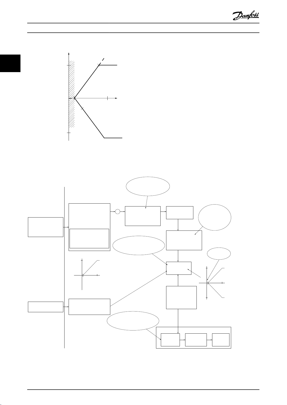
2.3.4
VVC+의 제어 구조
22
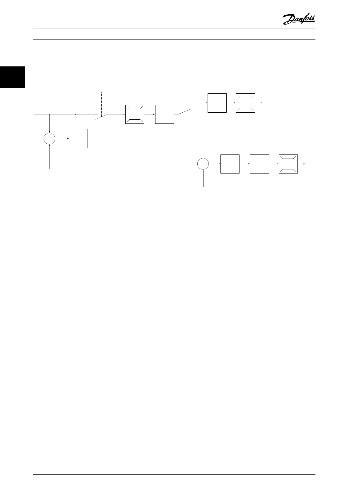
그림 2.14 VVC+ 개회로 구성 및 폐회로 구성의 제어 구조
그림 2.14
성 모드은 [0] 속도 개회로
에서와 같은 구성에서
로 설정되어 있습니다. 모터 제어기로 전달되기 전에 가감속 한계 및 속도 한계를 통해 지
파라미터 1-01 모터 제어 방식은 [1] VVC
령 처리 시스템에서 결과 지령이 수신되고 보내집니다. 그러면 모터 제어기의 출력이 최대 주파수 한계로 제한됩니
다.
+
로 설정되어 있으며
파라미터 1-00 구
파라미터 1-00 구성 모드가 [1] 속도 폐회로
어기로 전달됩니다. 속도 PID 제어 파라미터는
의 결과 지령은 최대 주파수 한계에 의해 제한된 모터 제어로 전달됩니다.
제어가 요구되는 어플리케이션에서 속도 또는 압력의 폐회로 제어에 공정 PID 제어를 사용하려면
성 모드
PID 제어기
20 Danfoss A/S © 03/2019 All rights reserved. MG06B539
에서
[3] 폐회로
있습니다.
로 설정되면 결과 지령이 가감속 한계와 속도 한계를 통해 속도 PID 제
파라미터 그룹 7-0* 속도 PID 제어
선택합니다. 공정 PID 파라미터는
에 있습니다. 속도 PID 제어에서
파라미터 그룹 7-2* 공정 제어기 피드백
파라미터 1-00 구
및
7-3* 공정
e30bp046.12
Hand
On
Off
Auto
On
Reset
제품 개요 설계 지침서
2.3.5
AC 드라이브에는 적분 전류 한계 제어 기능이 있습니다. 이 기능은 모터 전류와 그에 따른 토크가
터 4-16 모터 운전의 토오크 한계, 파라미터 4-17 재생 운전의 토오크 한계
한 토크 한계보다 높으면 활성화됩니다.
모터 운전 또는 회생 운전 시 AC 드라이브가 전류 한계에 도달했을 때, AC 드라이브는 모터 제어의 손실 없이 가능
한 빨리 프리셋 토크 한계 아래로 낮추려고 합니다.
VVC+ 모드에서의 내부 전류 제어
및
파라미터 4-18 전류 한계
파라미
에서 설정
2.3.6 현장 [Hand On] 및 원격 [Auto On] 제어
AC 드라이브는 현장 제어 패널(LCP)을 통해 수동으로 운전하거나 아날로그/디지털 입력 또는 필드버스를 통해 원격
으로 운전합니다.
LCP의 [Hand On] 및 [Off/Reset] 키를 눌러 AC 드라이브를 기동 및 정지합니다. 다음과 같은 셋업이 필요합니다.
파라미터 0-40 LCP의 [Hand on] 키
•
파라미터 0-44 LCP의 [Off/Reset] 키
•
파라미터 0-42 LCP의 [Auto on] 키
•
단자가 리셋으로 프로그래밍되어 있는 경우, [Off/Reset] 키 또는 디지털 입력을 통해 알람을 리셋합니다.
.
.
.
2 2
그림 2.15 LCP 제어 키
현장 지령은
현장 지령은 전원 차단 시 복원됩니다.
파라미터 1-00 구성 모드
의 설정과 관계 없이 구성 모드를 개회로로 강제 전환합니다.
MG06B539 Danfoss A/S © 03/2019 All rights reserved. 21

No function
Analog ref.
Pulse ref.
Local bus ref.
Preset relative ref.
Preset ref.
Local bus ref.
No function
Analog ref.
Pulse ref.
Analog ref.
Pulse ref.
Local bus ref.
No function
Local bus ref.
Pulse ref.
No function
Analog ref.
Input command:
Catch up/ slow down
Catchup Slowdown
value
Freeze ref./Freeze output
Speed up/ speed down
ref.
Remote
Ref. in %
-max ref./
+max ref.
Scale to
Hz
Scale to
Nm
Scale to
process
unit
Relative
X+X*Y
/100
DigiPot
DigiPot
DigiPot
max ref.
min ref.
DigiPot
D1
P 5-1x(15)
Preset '1'
External '0'
Process
Torque
Speed
open/closed loop
(1)
(2)
(3)
(4)
(5)
(6)
(7)
(0)
(0)
(1)
Relative scaling ref.
P 3-18
Ref.resource 1
P 3-15
Ref. resource 2
P 3-16
Ref. resource 3
P 3-17
200%
-200%
Y
X
-100%
100%
%
%
Ref./feedback range
P 3-00
Conguration mode
P 1-00
P 3-14
±100%
130BD374.10
P 16-01
P 16-02
P 3-12
P 5-1x(21)/P 5-1x(22)
P 5-1x(28)/P 5-1x(29)
P 5-1x(19)/P 5-1x(20)
P 3-04
Freeze ref.
&
increase/
decrease
ref.
Catch up/
slow
down
P 3-10
제품 개요
VLT® AutomationDrive FC 360
2.4 지령 처리
현장 지령
22
[Hand On]이 활성화된 상태로 AC 드라이브가 운전할 때 현장 지령이 활성화됩니다. [▲]/[▼] 및 [◄/[►]로 지령을
조정합니다.
원격 지령
원격 지령 계산을 위한 지령 처리 시스템은
그림 2.16
에서 보는 바와 같습니다.
그림 2.16 원격 지령
22 Danfoss A/S © 03/2019 All rights reserved. MG06B539
Resulting reference
Sum of all
references
Forward
Reverse
P 3-00 Reference Range= [0] Min-Max
130BA184.10
-P 3-03
P 3-03
P 3-02
-P 3-02
P 3-00 Reference Range =[1]-Max-Max
Resulting reference
Sum of all
references
-P 3-03
P 3-03
130BA185.10
제품 개요 설계 지침서
원격 지령은 매 스캐닝 시간마다 한 번씩 계산되며 처
음에는 다음 두 가지 지령 입력 유형으로 구성되어 있
습니다.
1. X(외부 지령): [Hz], [RPM], [Nm] 등의 단위
로 AC 드라이브가 감시하는 고정 프리셋 지령
(
파라미터 3-10 프리셋 지령
), 가변 아날로그
지령, 가변 디지털 펄스 지령 및 가변 필드버스
지령의 가능한 모든 조합(
리소스 1, 파라미터 3-16 지령 리소스 2
라미터 3-17 지령 3 소스
파라미터 3-15 지령
및
의 설정에 따라 결정)
으로서, 최대 4개의 외부에서 선택된 지령의
합(
파라미터 3-04 지령 기능
참조).
2. Y (상대 지령): [%]로 표시되는 단일 고정 프
리셋 지령(
단일 가변 아날로그 지령(
스케일링 지령 리소스
파라미터 3-14 프리셋 상대 지령
파라미터 3-18 상대
)의 합.
)과
두 가지 유형의 지령 입력은 다음과 같은 공식으로 결
합됩니다.
원격 지령=X+X*Y/100%.
상대 지령을 사용하지 않는 경우,
스케일링 지령 리소스는 [0] 기능 없음
터 3-14 프리셋 상대 지령
파라미터 3-18 상대
으로,
파라미
는 0%로 각각 설정합니다.
AC 드라이브의 디지털 입력은 캐치업/슬로우다운 기능
과 지령 고정 기능을 둘 다 활성화할 수 있습니다. 해당
기능과 파라미터는
로그래밍 지침서
아날로그 지령의 범위 설정은
로그 입력 53
있으며 디지털 펄스 지령의 범위 설정은
5-5* 펄스 입력
지령 한계 및 범위는
VLT® AutomationDrive FC 360 프
에 설명되어 있습니다.
파라미터 그룹 6-1* 아날
및
6-2* 아날로그 입력 54
에 설명되어
파라미터 그룹
에 설명되어 있습니다.
파라미터 그룹 3-0* 지령 한계
에
서 설정합니다.
파
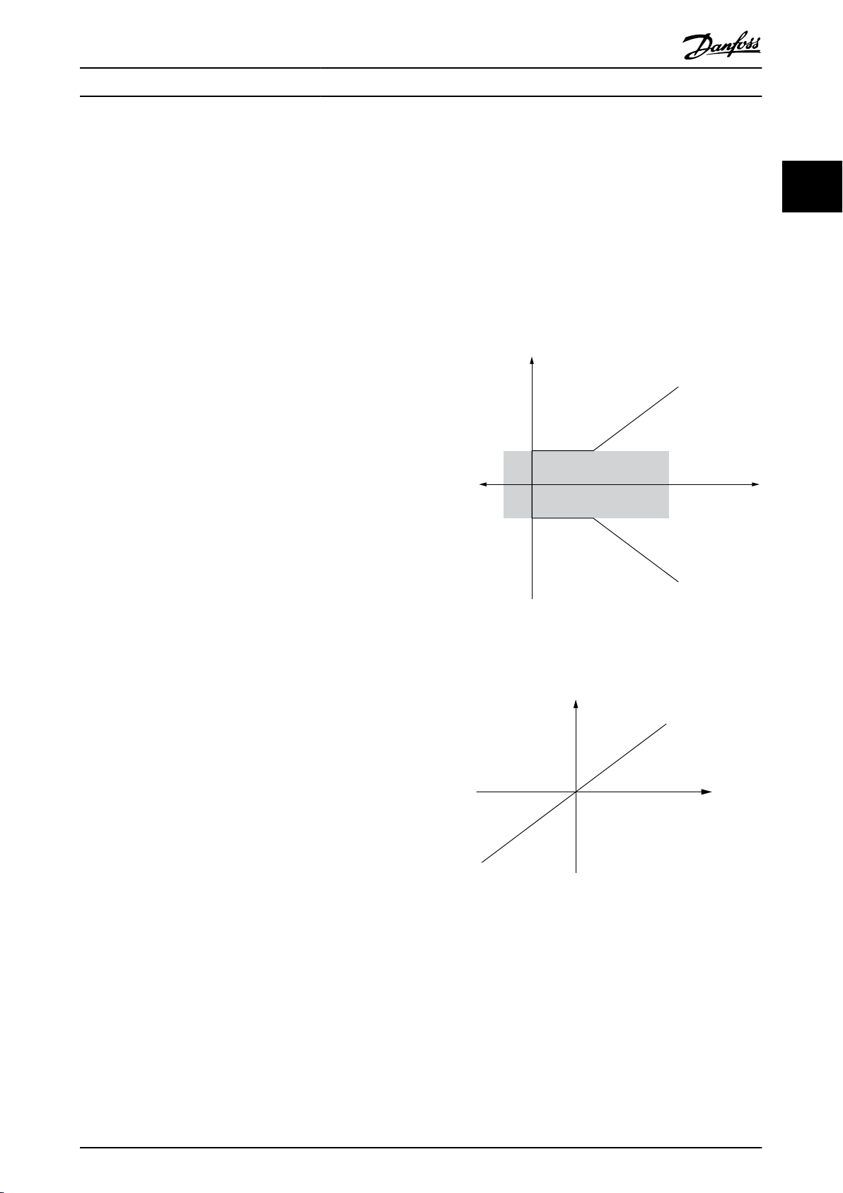
2.4.1 지령 한계
파라미터 3-00 Reference Range, 파라미
터 3-02 Minimum Reference
터 3-03 Maximum Reference
범위를 정의합니다. 모든 지령의 합은 필요할 때 잠깁니
다. 잠긴 후의 결과 지령과 모든 지령의 합 간의 관계는
그림 2.17
그림 2.17 지령 범위가 0으로 설정된 경우, 모든 지령의 합
및
그림 2.18
및
파라미
는 모든 지령 합의 허용
에서 보는 바와 같습니다.
2 2
MG06B539 Danfoss A/S © 03/2019 All rights reserved. 23
그림 2.18 지령 범위가 1로 설정된 경우, 모든 지령의 합
파라미터 1-00 Configuration Mode가 [3] 공정
설정되어 있지 않으면
Reference
값을 0 미만으로 설정할 수 없습니다. 이 경
파라미터 3-02 Minimum
으로
우에 잠긴 후의 결과 지령과 모든 지령의 합 간의 관계
는
그림 2.19
에서 보는 바와 같습니다.

130BA186.11
P 3-03
P 3-02
Sum of all
references
P 3-00 Reference Range= [0] Min to Max
Resulting reference
Resource output
[Hz]
Resource input
Terminal X
high
High reference/
feedback value
130BD431.10
8
[V]
50
10
P1
P2
10
Low reference/
feedback value
제품 개요
VLT® AutomationDrive FC 360
2.4.3 아날로그/펄스 지령 및 피드백의
범위 설정
22
아날로그 입력과 펄스 입력의 각각 지령과 피드백의 범
위는 동일한 방법으로 설정됩니다. 유일한 차이점은 지
령값이 피드백 값과는 달리 지정된 최소 종단점 이하이
그림 2.19 최소 지령이 음의 값으로 설정된 경우, 모든 지령
의 합
거나 최대 종단점 이상일 때 잠긴다는 점입니다(
림 2.20
에서 P1과 P2).
그
2.4.2 프리셋 지령 및 버스통신 지령의
범위 설정
프리셋 지령의 범위는 다음과 같은 규칙에 따라 설정됩
니다.
파라미터 3-00 지령 범위이 [0] 최소-최대
•
설정된 경우, 0% 지령은 0 [단위](여기서, 단
위는 RPM, m/s, bar 등 모든 단위 가능)과 같
고 100% 지령은 최대값(
지령
의 절대값,
Reference
파라미터 3-00 지령 범위이 [1] -최대–+최대
•
파라미터 3-02 Minimum
의 절대값)과 같습니다.
파라미터 3-03 최대
로 설정된 경우, 0% 지령은 0 [단위]과 같고
100% 지령은 최대 지령과 같습니다.
버스통신 지령의 범위는 다음과 같은 규칙에 따라 설정
됩니다.
파라미터 3-00 지령 범위이 [0] 최소–최대
•
설정된 경우, 0% 지령은 최소 지령과 같고
100% 지령은 최대 지령과 같습니다.
파라미터 3-00 지령 범위
•
이 [1]
-최대–+최대
로 설정된 경우, -100% 지령은 -최대 지령과
같고 100% 지령은 최대 지령과 같습니다.
로
로
그림 2.20 최소 및 최대 종단점
24 Danfoss A/S © 03/2019 All rights reserved. MG06B539
제품 개요 설계 지침서
종단점 P1 및 P2는 선택한 입력에 따라
입력 아날로그 53
전압 모드
P1=(최소 입력 값, 최소 지령 값)
최소 지령 값
최소 입력 값
P2=(최대 입력 값, 최대 지령 값)
최대 지령 값
최대 입력 값
파라미
터 6-14 Termi
nal 53 Low
Ref./Feedb.
Value
파라미
터 6-10 Termi
nal 53 Low
Voltage
[V]
파라미
터 6-15 Termi
nal 53 High
Ref./Feedb.
Value
파라미
터 6-11 Termi
nal 53 High
Voltage
[V]
표 2.3
에서 정의됩니다.
아날로그 53
전류 모드
파라미
터 6-14 Termina
l 53 Low Ref./
Feedb. Value
파라미
터 6-12 Termina
l 53 Low
Current
[mA]
파라미
터 6-15 Termina
l 53 High Ref./
Feedb. Value
파라미
터 6-13 Termina
l 53 High
Current
[mA]
아날로그 54
전압 모드
파라미
터 6-24 Termi
nal 54 Low
Ref./Feedb.
Value
파라미
터 6-20 Termi
nal 54 Low
Voltage
[V]
파라미
터 6-25 Termi
nal 54 High
Ref./Feedb.
Value
파라미
터 6-21 Termi
nal 54 High
Voltage
[V]
아날로그 54
전류 모드
파라미
터 6-24 Termin
al 54 Low Ref./
Feedb. Value
파라미
터 6-22 Termin
al 54 Low
Current
[mA]
파라미
터 6-25 Termin
al 54 High Ref./
Feedb. Value
파라미
터 6-23 Termin
al 54 High
Current
[mA]
펄스 입력 29 펄스 입력 33
파라미
터 5-52 Term.
29 Low Ref./
Feedb. Value
파라미
터 5-50 Term.
29 Low
Frequency
파라미
터 5-53 Term.
29 High Ref./
Feedb. Value
파라미
터 5-51 Term.
29 High
Frequency
파라미터 5-57 Term.
33 Low Ref./Feedb.
Value
파라미터 5-55 Term.
33 Low Frequency
[Hz]
[Hz]
파라미터 5-58 Term.
33 High Ref./Feedb.
Value
파라미터 5-56 Term.
33 High Frequency
[Hz]
[Hz]
2 2
표 2.3 P1 및 P2 종단점
2.4.4 0에 가까운 데드밴드
지령이 (흔치 않은 경우이기는 하지만 피드백도) 0에 가까운 데드밴드를 나타내 지령이 0에 가까울 때 설비가 정지
되는 경우가 있습니다.
데드밴드를 활성화하고 데드밴드의 크기를 설정하려면 다음을 수행합니다.
최소 지령 값(관련 파라미터는
•
가
그림 2.21
그래프의 범위를 정의하는 양쪽 종단점이 동일한 사분면에 있어야 합니다.
•
P1 또는 P2는
에서 X 축에 있어야 합니다.
그림 2.21
에서와 같이 데드밴드의 크기를 정의합니다.
표 2.3
참조) 또는 최대 지령 값을 0에서 설정합니다. 다시 말해, P1이나 P2
MG06B539 Danfoss A/S © 03/2019 All rights reserved. 25
Resource output
[Hz] or “No unit”
Resource input
[mA]
Quadrant 2
Quadrant 3
Quadrant 1
Quadrant 4
Terminal X high
Low reference/feedback
value
High reference/feedback
value
1
-50
165020
P1
P2
0
130BD446.10
forward
reverse
Terminal low
20
1
10
V
V
20
1
10
-20
130BD454.10
+
Analog input 53
Low reference 0 Hz
High reference 20 Hz
Low voltage 1 V
High voltage 10 V
Ext. source 1
Range:
0.0% (0 Hz)
100.0% (20 Hz)
100.0% (20 Hz)
Ext. reference
Range:
0.0% (0 Hz)
20 Hz 10V
Ext. Reference
Absolute
0 Hz 1 V
Reference
algorithm
Reference
100.0% (20 Hz)
0.0% (0 Hz)
Range:
Limited to:
0%- +100%
(0 Hz- +20 Hz)
Limited to: -200%- +200%
(-40 Hz- +40 Hz)
Reference is scaled
according to min
max reference giving a
speed.!!!
Scale to
speed
+20 Hz
-20 Hz
Range:
Speed
setpoint
Motor
control
Range:
-8 Hz
+8 Hz
Motor
Digital input 19
Low No reversing
High Reversing
Limits Speed Setpoint
according to min max speed.!!!
Motor PID
Hz
Hz
Dead band
Digital input
General Reference
parameters:
Reference Range: Min - Max
Minimum Reference: 0 Hz (0,0%)
Maximum Reference: 20 Hz (100,0%)
General Motor
parameters:
Motor speed direction:Both directions
Motor speed Low limit: 0 Hz
Motor speed high limit: 8 Hz
제품 개요
VLT® AutomationDrive FC 360
22
그림 2.21 데드밴드의 크기
사례 1: 데드밴드가 있는 정 지령, 역회전 기동을 위한 디지털 입력, I부
그림 2.22
는 최소에서 최대 범위 내에 있는 지령 입력이 어떻게 제한하는지를 나타냅니다.
그림 2.22 최소에서 최대 범위 내에 있는 지령 입력의 제한
26 Danfoss A/S © 03/2019 All rights reserved. MG06B539

+
30 Hz
1
10
20 Hz
1
10
130BD433.11
-20 Hz
V
V
Analog input 53
Low reference 0 Hz
High reference 20 Hz
Low voltage 1 V
High voltage 10 V
Ext. source 1
Range:
0.0% (0 Hz)
150.0% (30 Hz)
150.0% (30 Hz)
Ext. reference
Range:
0.0% (0 Hz)
30 Hz 10 V
Ext. Reference
Absolute
0 Hz 1 V
Reference
algorithm
Reference
100.0% (20 Hz)
0.0% (0 Hz)
Range:
Limited to:
-100%- +100%
(-20 Hz- +20 Hz)
Limited to: -200%- +200%
(-40 Hz- +40 Hz)
Reference is scaled
according to
max reference giving a
speed.!!!
Scale to
speed
+20 Hz
-20 Hz
Range:
Speed
setpoint
Motor
control
Range:
–10 Hz
+10 Hz
Motor
Digital input 19
Low No reversing
High Reversing
Limits Speed Setpoint
according to min max speed.!!!
Motor PID
Dead band
Digital input
General Reference
parameters:
Reference Range: -Max - Max
Minimum Reference: Don't care
Maximum Reference: 20 Hz (100.0%)
General Motor
parameters:
Motor speed direction: Both directions
Motor speed Low limit: 0 Hz
Motor speed high limit: 10 Hz
제품 개요 설계 지침서
사례 2: 데드밴드가 있는 정 지령, 역회전 기동을 위한 디지털 입력, II부
그림 2.23
는 외부 지령을 추가하기 전에 –최대에서 +최대 범위를 벗어난 지령 입력이 어떻게 입력을 최저 한계와 최
고 한계로 제한하는지 뿐만 아니라 외부 지령이 지령 알고리즘에 의해 어떻게 –최대에서 +최대로 제한되는지를 나
타냅니다.
2 2
그림 2.23 -최대에서 +최대 범위를 벗어난 지령 입력의 제한
MG06B539 Danfoss A/S © 03/2019 All rights reserved. 27

제품 개요
VLT® AutomationDrive FC 360
2.5 PID 제어
2.5.1 속도 PID 제어
22
파라미터 1-00 Configuration Mode
[0] 개회로
[1] 속도 폐 회로
[2] 토오크
[3] 폐회로
표 2.4 제어 구성, 활성 속도 제어
1) 활성화되지 않음은 해당 모드가 있기는 하지만 속도 제어가 활성화되지 않음을 의미합니다.
2) 해당 없음은 해당 모드가 전혀 없음을 의미합니다.
파라미터 기능 설명
파라미터 7-00 Speed PID Feedback Source
파라미터 7-02 속도 PID 비례 이득
파라미터 7-03 Speed PID Integral Time
파라미터 7-04 Speed PID Differentiation
Time
파라미터 7-05 Speed PID Diff. Gain Limit
파라미터 7-06 Speed PID Lowpass Filter
Time
파라미터 1-01 Motor Control Principle
U/f
활성화되지 않음
해당 없음
해당 없음 활성화되지 않음
활성화되지 않음 활성화되지 않음
속도 PID의 피드백 소스를 선택합니다.
값이 클수록 더욱 신속히 제어할 수 있습니다. 하지만 값이 지나치게 높으면 공진 현상이 발생할
수 있습니다.
정상 상태 속도 오류 원인을 제거합니다. 값이 낮을수록 반응이 빠릅니다. 하지만 값이 지나치게
낮으면 공진 현상이 발생할 수 있습니다.
피드백 변화율에 대한 비례 이득을 제공합니다. 0으로 설정하면 미분기를 사용할 수 없습니다.
어플리케이션에서 지령 및 피드백이 신속히 변화할 때 – 이는 오류가 신속히 변화되는 것을 의미
하는데 – 곧 미분기가 과도한 영향력을 지니게 됩니다. 이는 미분기가 오류에서 발생된 변화에 반
응하기 때문입니다. 오류가 신속히 변화할수록 미분기 이득은 더욱 커집니다. 따라서 미분기 이득
이 완만한 변화에 알맞은 미분 시간과 급격한 변화에 알맞은 순간 이득을 설정하도록 제한할 수
있습니다.
저역통과필터는 피드백 신호의 공진을 감소시키고 정상 상태의 성능을 향상시킵니다. 하지만 필터
시간이 너무 길면 속도 PID 제어의 다이나믹 성능을 저하시킵니다.
엔코더의 회전수당 펄스(PPR)에 따른
정:
엔코더 PPR
512 10 ms
1024 5 ms
2048 2 ms
4096 1 ms
1)
2)
파라미터 7-06 속도 PID 저주파 통과 필터 시간
+
VVC
활성화되지 않음
활성화
의 실제 설
파라미터 7-06 Speed PID Lowpass Filter
Time
표 2.5 속도 제어 파라미터
속도 제어 프로그래밍의 예
이 예에서 속도 PID 제어는 모터의 부하 변화와 관계 없이 일정한 모터 회전수를 유지하는데 사용됩니다. 필요한 모
터 회전수는 단자 53에 연결된 가변 저항을 통해 설정됩니다. 속도 범위는 가변 저항에 따라 0–10 V에 해당하는 0–
1500 RPM입니다. 단자 18에 연결된 스위치는 기동 및 정지를 제어합니다. 속도 PID는 24V (HTL) 인크리멘탈 엔
코더를 피드백으로 사용하여 모터의 실제 RPM을 감시합니다. 피드백 센서는 단자 32와 33에 연결된 엔코더 (회전수
당 1024 펄스)입니다. 단자 32와 33의 펄스 주파수 범위는 4 Hz–32 kHz입니다.
28 Danfoss A/S © 03/2019 All rights reserved. MG06B539

M
3
96 97 9998
91 92 93 95
50
12
L1 L2L1PEL3
W PEVU
F1
L2
L3
N
PE
18
53
27
55
32
33
24 Vdc
130BD372.11
제품 개요 설계 지침서
2 2
그림 2.24 속도 제어 프로그래밍
표 2.6
의 단계를 따라 속도 제어를 프로그래밍합니다(
표 2.6
에서 다른 모든 파라미터와 스위치가 초기 설정값이라고 가정합니다.
프로그래밍 지침서
의 설정 방법 참조).
기능 파라미터 번호 설정
1) 모터가 정상적으로 운전하는지 확인하려면 다음 사항을 확인합니다.
명판의 데이터를 사용하여 모터 파라미터를 설정합니다.
AMA를 수행합니다.
2) 모터가 정상적으로 작동하고 엔코더가 올바르게 연결되었는지 점검합니다. 다음 사항을 확인합니다.
[Hand On]을 누릅니다. 모터가 구동 중인지 점검하고 회전 방
향을 확인합니다(정회전으로 간주).
3) AC 드라이브 한계를 안전한 값으로 설정합니다.
지령에 대한 허용 한계를 설정합니다.
가감속 설정값이 AC 드라이브 용량과 운전 사양에 알맞는지 확
인합니다.
모터 회전수 및 주파수에 대한 허용 한계를 설정합니다.
4) 속도 제어를 구성하고 모터 제어 방식을 선택합니다.
속도 제어 활성화
모터 제어 방식 선택
5) 속도 제어에 대한 지령을 구성하고 범위를 설정합니다.
아날로그 입력 53을 지령 소스로 설정합니다.
파라미터 그룹 1-2* 모터
데이터
파라미터 1-29 자동 모터
최적화 (AMA)
정 지령을 설정합니다.
파라미터 3-02 최소 지령
파라미터 3-03 최대 지령
파라미터 3-41 1 가속 시간
파라미터 3-42 1 감속 시간
파라미터 4-12 모터 속도
하한 [Hz]
파라미터 4-14 모터 속도
상한 [Hz]
파라미터 4-19 최대 출력
주파수
파라미터 1-00 구성 모드 [1] 속도 폐 회로
파라미터 1-01 모터 제어
방식
파라미터 3-15 지령 리소스
1
모터 명판에 명시된 내용과 동일하게 설정.
[1] 완전 AMA 사용함
0
50
초기 설정
초기 설정
0 Hz
50 Hz
60 Hz
+
[1] VVC
필요 없음 (초기 설정값)
MG06B539 Danfoss A/S © 03/2019 All rights reserved. 29

제품 개요
VLT® AutomationDrive FC 360
아날로그 입력 53의 범위를 0 Hz (0 V)에서 50 Hz (10 V)로
설정
6) 24 V HTL 엔코더 신호를 모터 제어 및 속도 제어에 대한 피드백으로 구성합니다.
22
디지털 입력 32와 33을 엔코더 입력으로 설정합니다.
단자 32/33을 속도 PID 피드백으로 선택합니다.
7) 속도 제어 PID 파라미터를 튜닝합니다.
이에 해당하거나 직접 튜닝할 때는 튜닝 지침을 참조하십시오.
8) 종료:
안전을 위해 파라미터 설정값을 LCP에 저장합니다.
파라미터 그룹 6-1* 아날로
그 입력 53
파라미터 5-14 단자 32 디
지털 입력
파라미터 5-15 단자 33 디
지털 입력
파라미터 7-00 속도 PID
피드백 소스
파라미터 그룹 7-0* 속도
PID 제어
파라미터 0-50 LCP Copy [1] 모두 업로드
필요 없음 (초기 설정값)
[82] Encoder input B (엔코더 입력 B)
[83] Encoder input A (엔코더 입력 A)
[1] 24V 엔코더
표 2.6 속도 PID 제어의 프로그래밍 순서
30 Danfoss A/S © 03/2019 All rights reserved. MG06B539

P 7-30
normal/inverse
PID
P 7-38
*(-1)
Feed forward
Reference
Handling
Feedback
Handling
% [unit]
% [unit]
%
[unit]
%
[speed]
Scale to
speed
P 4-10
Motor speed
direction
To motor
control
Process PID
130BA178.10
_
+
0%
-100%
100%
0%
-100%
100%
제품 개요 설계 지침서
2.5.2 공정 PID 제어
공정 PID 제어는 센서(예를 들어, 압력, 온도, 유량 등)에 의해 측정되고 펌프, 팬 또는 연결된 장치를 통해 연결된
모터에 영향을 줄 수 있는 어플리케이션 파라미터를 제어하는데 사용할 수 있습니다.
표 2.7
는 공정 제어가 가능한 제어 구성을 나타냅니다. 속도 제어가 활성화된 영역을 보려면
장을 2.3 제어 구조
를
참조하십시오.
파라미터 1-00 구성 모드 파라미터 1-01 모터 제어 방식
VVC
+
[3] 폐회로
U/f
해당 없음 폐회로
표 2.7 제어 구성
주의 사항
공정 제어 PID는 초기 파라미터 설정으로 실행되지만 어플리케이션 제어 성능을 최적화하려면 파라미터를 튜닝하는
것이 좋습니다.
2 2
그림 2.25 공정 PID 제어 다이어그램
MG06B539 Danfoss A/S © 03/2019 All rights reserved. 31

제품 개요
VLT® AutomationDrive FC 360
2.5.3 공정 제어 관련 파라미터
파라미터 기능 설명
22
파라미터 7-20 공정 폐회로 피드백 1 리소스
파라미터 7-22 공정 폐회로 피드백 2 리소스
파라미터 7-30 공정 PID 정/역 제어 [0] 정
파라미터 7-31 PID 와인드업 방지
파라미터 7-32 공정 PID 기동 속도
파라미터 7-33 공정 PID 비례 이득
파라미터 7-34 공정 PID 적분 시간
파라미터 7-35 공정 PID 미분 시간
파라미터 7-36 공정 PID 미분 이득 한계
파라미터 7-38 공정 PID 피드포워드 상수
파라미터 6-16 단자 53 필터 시정수
•
그 단자 53)
파라미터 6-26 단자 54 필터 시정수
•
그 단자 54)
(아날로
(아날로
공정 PID의 피드백 소스(아날로그 또는 펄스 입력)를 선택합니다.
선택사양: 공정 PID의 추가 피드백 신호 필요 여부와 추가 피드백 소스를 설정합니다. 추가 피드
백 소스를 선택하면 공정 PID 제어에 사용되기 전에 두 개의 피드백 신호가 추가됩니다.
[1] 역
와인드업 방지 기능은 주파수나 토크가 한계에 도달했을 때 적분기를 실제 주파수에 해당하는 이
득으로 설정합니다. 이는 속도 변화로도 보상할 수 없는 오류의 적분을 방지합니다.
눌러 이 기능을 비활성화합니다.
일부 어플리케이션의 경우, 필요한 속도/설정포인트에 도달하는 데 시간이 오래 걸릴 수 있습니
다. 이러한 어플리케이션에서는 공정 제어가 활성화되기 전에 AC 드라이브에서 고정 모터 회전
수를 설정하는 것이 좋을 수도 있습니다.
값(회전수)을 설정하여 고정 모터 회전수를 설정합니다.
값이 클수록 더욱 신속히 제어할 수 있습니다. 하지만 값이 지나치게 크면 공진 현상이 발생할
수 있습니다.
정상 상태 속도 오류 원인을 제거합니다. 값이 낮을수록 반응이 빠릅니다. 하지만 값이 지나치게
작으면 공진 현상이 발생할 수 있습니다.
피드백 변화율에 대한 비례 이득을 제공합니다. 0으로 설정하면 미분기를 사용할 수 없습니다.
어플리케이션에서 지령 및 피드백이 신속히 변화할 때(오류가 신속히 변화되는 것을 의미함) 곧
미분기가 과도한 영향력을 지니게 됩니다. 이는 미분기가 오류에서 발생된 변화에 반응하기 때문
입니다. 오류가 신속히 변화할수록 미분기 이득은 더욱 커집니다. 따라서 미분기 이득이 완만한
변화에 알맞은 미분 시간을 설정하도록 제한할 수 있습니다.
공정 지령과 공정 지령을 확보하는데 필요한 모터 회전수 간의 상관관계가 양호한 (그리고 대략
적으로 선형인) 어플리케이션의 경우, 공정 PID 제어의 다이나믹 성능을 향상시키는데 피드포워
드 인수를 사용할 수 있습니다.
전류/전압 피드백 신호에 공진이 발생한 경우, 저역통과필터를 사용하여 이러한 공진을 감소시킬
수 있습니다.
예: 저역통과필터 값이 0.1초로 설정되면, 속도 한계는 10 RAD/초 (0.1초의 역수)가 되며 이는
(10/(2 x π))=1.6Hz에 해당합니다. 이는 필터가 초당 1.6 이상의 공진을 발생시키는 모든 전류/
전압을 제거함을 의미합니다. 주파수(속도)가 1.6Hz 이하인 피드백 신호만 제어됩니다.
저역통과필터는 정상 상태의 성능을 향상시키지만 너무 긴 필터 시간을 선택하면 공정 PID 제어
의 다이나믹 성능이 저하됩니다.
운전을 선택하면 공정 제어는 피드백이 지령보다 낮을 경우 모터 회전수를 증가시킵니다.
운전을 선택하면 공정 제어는 모터 회전수를 감소시킵니다.
[0] 꺼짐
파라미터 7-32 공정 PID 기동 속도
에서 공정 PID 기동
을
표 2.8 공정 제어 파라미터
32 Danfoss A/S © 03/2019 All rights reserved. MG06B539

Transmitter
96 97 9998
91 92 93 95
50
12
L1 L2L1PEL3
W PEVU
F1
L2
L3
N
PE
130BD373.10
18
53
27
55
54
M
3
제품 개요 설계 지침서
2.5.4 공정 PID 제어의 예
그림 2.26
은 환기 시스템에 사용된 공정 PID 제어의 예
입니다.
그림 2.26 환기 시스템의 공정 PID 제어
환기 시스템에서 온도는 0–10 V의 가변 저항과 함께
-5 - +35 °C (23–95 °F)로 설정할 수 있습니다. 설정
된 온도를 일정하게 유지하기 위해 공정 제어를 사용합
니다.
역 제어 방식을 사용하는데, 이는 온도가 상승할 때 환
기 속도도 증가하여 더 많은 공기가 발생하는 것을 의
미합니다. 온도가 하락하면 속도도 감소합니다. 사용된
트랜스미터는 -10 - +40 °C (14–104 °F), 4–20 mA
의 운전 범위를 가진 온도 센서입니다.
2 2
그림 2.27 2선 트랜스미터
1. 단자 18에 연결된 스위치를 통한 기동/정지.
2. 단자 53에 연결된 가변 저항(-5 - +35 °C
(23–95 °F), 0–10 V DC)을 통한 온도 지령.
3. 단자 54에 연결된 트랜스미터(-10 - +40 °C
(14–104 °F), 4–20 mA)를 통한 온도 피드백.
기능 파라미터 번호설정
AC 드라이브를 초기화합니다.
1) 모터 파라미터를 설정합니다:
명판 데이터에 따라 모터 파라미터를 설정합니다.
완전 AMA를 수행합니다.
2) 모터의 회전 방향이 올바른지 점검합니다.
모터가 AC 드라이브에 U-U, V-V, W-W와 같이 정회전 위상 순서로 연결되면 축 끝에서 봤을 때 모터축이 일반적으로 시계 방향으로 회전합니다.
[Hand On]을 누릅니다. 수동 지령을 적용하여 축 방
향을 점검합니다.
모터가 원하는 방향과 정반대 방향으로 회전하는 경우:
1.
파라미터 4-10 모터 속도 방향
변경합니다.
2. 주전원을 차단하고 DC 링크가 방전될 때까지 기다
립니다.
3. 모터 위상 중 2개를 전환합니다.
에서 모터 방향을
파라미
터 14-22 운전
모드
파라미터 그룹
1-2* 모터 데
이터
파라미
터 1-29 자동
모터 최적화
(AMA)
파라미
터 4-10 모터
회전 방향
[2] 초기화
모터 명판에 기재된 내용과 동일하게 설정.
[1] 완전 AMA 사용함
올바른 모터축 방향을 선택합니다.
- 전원 재투입 실시 - 리셋 누름.
.
MG06B539 Danfoss A/S © 03/2019 All rights reserved. 33

제품 개요
VLT® AutomationDrive FC 360
기능 파라미터 번호설정
구성 모드를 설정합니다.
22
파라미
터 1-00 구성
[3] 폐회로
.
모드
3) 지령 구성(즉, 지령 처리를 위한 범위)을 설정합니다.
지령/피드백 단위를 설정합니다.
최소 지령(10 °C (50 °F))을 설정합니다.
최대 지령(80 °C (176 °F))을 설정합니다.
프리셋 값(배열 파라미터)에서 설정 값이 정해진 경우,
다른 지령 소스를
[0] 기능 없음
으로 설정합니다.
파라미터 그룹 6-** 아날로그 입/출력
파라미터 3-01
Reference/
Feedback Unit
파라미터 3-02
Minimum
Reference
파라미터 3-03
Maximum
[60] °C
단위(표시창에 나타난 단위).
-5 °C (23 °F).
35 °C (95 °F).
[0] 35%
.
Ref =
Par . 3 − 10
0
× Par . 3 − 03 − par . 3 − 02 = 24, 5°C
100
파라미터 3-14 Preset Relative Reference
Scaling Reference Resource [0] = 기능 없음
에서 아날로그 입력의 범위를 설정합니다.
-
파라미터 3-18 Relative
.
Reference
파라미터 3-10
Preset
Reference
4) AC 드라이브의 각종 한계를 조정합니다:
가감속 시간으로 알맞은 값인 20초로 설정합니다.
파라미터 3-41
Ramp 1 Ramp
20 s
20 s
Up Time
파라미터 3-42
Ramp 1 Ramp
Down Time
최소 속도 한계를 설정합니다.
모터 회전수 최대 한계를 설정합니다.
최대 출력 주파수를 설정합니다.
파라미터 4-12
Motor Speed
Low Limit
10 Hz
50 Hz
60 Hz
[Hz]
파라미터 4-14
Motor Speed
High Limit
[Hz]
파라미터 4-19
Max Output
Frequency
파라미터 6-19 Terminal 53 mode
5) 지령 및 피드백에 사용되는 아날로그 입력의 범위를 설정합니다.
단자 53 최저 전압을 설정합니다.
단자 53 고전압을 설정합니다.
단자 54 최저 피드백 값을 설정합니다.
단자 54 최고 피드백 값을 설정합니다.
피드백 소스를 설정합니다.
및
파라미터 6-29 Terminal 54 mode
파라미터 6-10
Terminal 53
Low Voltage
파라미터 6-11
Terminal 53
를 전압 또는 전류 모드로 설정합니다.
0 V
10V
-5 °C (23 °F)
35 °C (95 °F)
[2] 아날로그 입력 54
High Voltage
파라미터 6-24
Terminal 54
Low Ref./
Feedb. Value
파라미터 6-25
Terminal 54
High Ref./
Feedb. Value
파라미터 7-20
Process CL
Feedback 1
Resource
34 Danfoss A/S © 03/2019 All rights reserved. MG06B539

제품 개요 설계 지침서
기능 파라미터 번호설정
6) 기본 PID 설정:
공정 PID 정/역.
공정 PID 와인드업 방지.
공정 PID 시작 속도.
파라미터를 LCP에 저장합니다.
표 2.9 공정 PID 제어 셋업의 예
파라미터 7-30
Process PID
Normal/
Inverse
Control
파라미터 7-31
Process PID
Anti Windup
파라미
터 7-32 공정
PID 시작 속도
파라미
터 0-50 LCP
복사
[0] 정
[1] 켜짐
300RPM
[1] 모두 업로드
2 2
2.5.5 공정 컨트롤러 최적화
장을 2.5.5 프로그래밍 순서
구성한 후, 비례 이득, 적분 시간 및 미분 시간(
터 7-33 공정 PID 비례 이득, 파라미터 7-34 공정
PID 적분 시간
및
파라미터 7-35 공정 PID 미분 시간
을 최적화합니다. 대부분의 공정에서 다음 절차를 완료
합니다.
1. 모터를 기동합니다.
2.
파라미터 7-33 공정 PID 비례 이득
설정하고 피드백 신호가 다시 지속적으로 변화
하기 시작할 때까지 값을 늘립니다. 피드백 신
호가 안정화될 때까지 값을 줄입니다. 비례 이
득을 40–60%까지 낮춥니다.
3.
파라미터 7-34 공정 PID 적분 시간
설정하고 피드백 신호가 다시 지속적으로 변화
하기 시작할 때까지 값을 줄입니다. 피드백 신
호가 안정화될 때까지 적분 시간을 늘리면 결
과적으로 적분 시간이 15-50%까지 늘어납니
다.
4. 빠르게 작동하는 시스템에만
터 7-35 공정 PID 미분 시간
용합니다. 일반적으로 미분 시간의 값은 적분
시간의 4배입니다. 비례 이득과 적분 시간의
설정이 완전히 최적화된 경우, 미분기를 사용
합니다. 저역통과필터가 피드백 신호의 공진을
충분히 감소시키는지 확인합니다.
에 설명된 대로 기본 설정을
파라미
을 0.3으로
를 20초로
파라미
(미분 시간)를 사
주의 사항
필요한 경우, 피드백 신호가 변화하도록 하기 위해 기
동/정지를 여러 번 반복할 수 있습니다.
2.5.6 Ziegler Nichols 튜닝 방법
AC 드라이브의 PID 제어를 튜닝하기 위해 댄포스는
Ziegler Nichols 튜닝 방법을 권장합니다.
)
주의 사항
다소 불안정한 제어 설정값에 의해 발생한 공진으로 인
해 손상될 수 있는 어플리케이션에서는 Ziegler
Nichols 튜닝 방법을 사용하지 마십시오.
응답 결과가 아닌 안정성 한계에 따라 시스템을 연산하
는 것이 파라미터 설정 변경 기준입니다. (피드백에서
측정된) 공진이 지속적으로 발생할 때까지, 즉 시스템이
다소 불안정해질 때까지 비례 이득을 증가시킵니다. 해
당 이득
보되는 시점의 이득입니다. (최종 단계의 시점이라고도
하는) 공진 시점(
결정되며 공진의 진폭이 작을 때 측정해야 합니다.
공정 운영자는 만족할 만한 제어 결과를 얻을 때까지
제어의 최종 설정을 반복적으로 변경할 수 있습니다.
(Ku)
은 최종 단계의 이득이라고 하며 공진이 확
P
)은
u
그림 2.28
에서 보는 바와 같이
1. 비례 제어만을 선택합니다. 이 때 적분 시간은
최대값으로 설정되어 있는 반면 미분 시간은 0
으로 설정되어 있습니다.
2. 불안정점에 도달 (지속적인 공진)하고 주요 이
득 값
K
가 한계에 도달할 때까지 비례 이득
u
값을 늘립니다.
3. 주요 시간상수 ,
P
를 얻기 위해 공진 기간을
u
측정합니다.
4. 필요한 PID 제어 파라미터는
표 2.10
여 계산합니다.
를 활용하
MG06B539 Danfoss A/S © 03/2019 All rights reserved. 35

130BA183.10
y(t)
t
P
u
제품 개요
22
그림 2.28 다소 불안정한 시스템
VLT® AutomationDrive FC 360
제어 유형 비례 이득 적분 시간 미분 시간
PI 제어 0.45 x
PID 정밀 제어 0.6 x
PID 과도 현상 0.33 x
표 2.10 조절기에 대한 Ziegler Nichols 튜닝
K
K
u
K
0.833 x
0.5 x
0.5 x
P
u
P
u
P
u
u
u
0.125 x
0.33 x
–
P
u
P
u
2.6 EMC 방사 및 내성
2.6.1 EMC 방사의 일반적 측면
전기적 간섭은 150 kHz에서 30 MHz 범위 내의 주파수에서 발생합니다. 30 MHz에서 1 GHz 범위에 있는 AC 드라
이브 시스템의 공기 중 부유물에 의한 간섭은 AC 드라이브, 모터 케이블, 모터 등에서 발생합니다.
모터 전압에서 높은 dU/dt가 모터 케이블의 용량형 전류와 결합하면 누설 전류의 원인이 됩니다.
차폐 케이블은 비차폐 케이블에 비해 커패시턴스가 크기 때문에 차폐된 모터 케이블을 사용하면 누설 전류가 증가합
니다(
그림 2.29
참조). 누설 전류가 필터링되지 않으면 약 5MHz 이하의 무선 주파수 범위에서 주전원에 대한 간섭이
증가합니다. 누설 전류(I1)는 차폐(I3)를 통해 유닛으로 다시 보내지므로 차폐된 모터 케이블의 전자기장(I4)은 작습니
다.
차폐는 방사 간섭을 감소시키지만 주전원에 대한 저주파수 간섭을 증가시킵니다. 모터 케이블 차폐를 AC 드라이브
외함과 모터 외함에 연결합니다. 차폐 클램프를 사용하여 차폐의 양쪽 끝(돼지꼬리 모양)이 꼬이지 않도록 고정시키
는 것이 가장 좋습니다. 차폐 클램프는 고주파에서 차폐 임피던스를 증가시켜 차폐 효과를 감소시키고 누설 전류(I4)
를 증가시킵니다.
다음과 같은 목적으로 차폐 케이블이 사용되는 경우, 외함의 양쪽 끝에 차폐를 장착합니다.
필드버스
•
네트워크
•
릴레이
•
제어 케이블
•
신호 인터페이스
•
제동
•
하지만 전류 루프 발생을 피하기 위해 차폐를 차단해야 하는 경우도 있습니다.
36 Danfoss A/S © 03/2019 All rights reserved. MG06B539

1
2
z
z
z
L1
L2
L3
PE
U
V
W
C
S
I
2
I
1
I
3
I
4
C
S
C
S
C
S
C
S
I
4
C
S
z
PE
3
4
5
6
175ZA062.12
제품 개요 설계 지침서
1 접지 케이블
2 쉴드
3 교류 주전원 공급
4 AC 드라이브
5 차폐형 모터 케이블
6 모터
2 2
그림 2.29 EMC 방사
AC 드라이브의 마운팅 플레이트에 차폐를 장착하는 경우, 금속 마운팅 플레이트를 사용하여 차폐 전류가 유닛으로
다시 전달되도록 합니다. 마운팅 플레이트에서 AC 드라이브의 섀시까지 가능한 높은 전기적 접촉을 얻기 위해 장착
용 나사로 고정시켜야 합니다.
비차폐 케이블을 사용하면 내성 요구사항은 충족하더라도 방사 요구사항은 일부 충족하지 않을 수 있습니다.
전체 시스템(유닛 및 설비)의 간섭 수준을 낮추려면 모터 및 제동 케이블을 가능한 짧게 합니다. 신호 레벨이 민감한
케이블을 주전원, 모터 및 제동 케이블과 나란히 배선하지 마십시오. 50MHz(공기 중) 이상의 무선 간섭은 제어 전자
장치에 의해 특히 많이 발생합니다.
MG06B539 Danfoss A/S © 03/2019 All rights reserved. 37

제품 개요
2.6.2 EMC 방사 요구사항
VLT® AutomationDrive FC 360
표 2.11
22
습니다.
의 시험 결과는 AC 드라이브(마운팅 플레이트 포함), 모터 및 차폐 모터 케이블이 있는 시스템을 통해 얻었
외함 용량 및 정격 동력
J1 0.37–2.2 kW (0.5–3.0 hp), 380–480 V – – 25 m (82 ft) 예
A1
필터
A2
필터
표 2.11 EMC 방사(필터 유형: 내부)
J2 3.0–5.5 kW (4.0–7.5 hp), 380–480 V – – 25 m (82 ft) 예
J3 7.5 kW (10 hp), 380–480 V – – 25 m (82 ft) 예
J4 11–15 kW (15–20 hp), 380–480 V – – 25 m (82 ft) 예
J5 18.5–22 kW (25–30 hp), 380–480 V – – 25 m (82 ft) 예
J1 0.37–2.2 kW (0.5–3.0 hp), 380–480 V 5 m (16.4 ft)
J2 3.0–5.5 kW (4.0–7.5 hp), 380–480 V 5 m (16.4 ft)
J3 7.5 kW (10 hp), 380–480 V 5 m (16.4 ft)
J4 11–15 kW (15–20 hp), 380–480 V 5 m (16.4 ft)
J5 18.5–22 kW (25–30 hp), 380–480 V 5 m (16.4 ft)
J6 30–45 kW (40–60 hp), 380–480 V 25 m (82 ft)
J7 55–75 kW (75–100 hp), 380–480 V 25 m (82 ft)
클래스 A 그룹 2/EN 55011
산업 환경
범주 C3/EN/IEC 61800-3
2차 환경
전도 방사 전도 방사
1)
예
1)
예
1)
예
1)
예
1)
예
1)
예
1)
예
클래스 A 그룹 1/EN 55011
산업 환경
범주 C2/EN/IEC 61800-3
1차 환경(제한적)
– –
– –
– –
– –
– –
– –
– –
1) 150 kHz에서 30 MHz의 주파수 범위는 IEC/EN 61800-3과 EN 55011에서 서로 일치하지 않으며 반드시 포함되는 것도 아닙
니다.
2.6.3 EMC 내성 요구사항
AC 드라이브의 내성 요구사항은 설치되는 환경에 따라 다릅니다. 산업 환경은 가정 및 사무실 환경보다 높은 요구사
항을 필요로 합니다. 모든 댄포스 AC 드라이브는 산업 환경의 요구사항을 충족합니다. 따라서 안전성이 높은 가정
및 사무실 환경의 낮은 요구사항 또한 충족합니다.
전기적 현상에 따른 버스트 과도 현상에 대한 내성을 문서화하기 위해 다음으로 구성된 시스템에 대한 내성 시험이
아래와 같이 실시되었습니다.
AC 드라이브(해당하는 경우, 옵션 포함).
•
차폐 제어 케이블.
•
가변 저항, 모터 케이블 및 모터 포함 제어 박스.
•
시험은 다음 적용 기준에 따라 이루어졌습니다.
EN 61000-4-2 (IEC 61000-4-2) 정전기 방전(ESD): 사용자로부터의 정전기 방전 실험.
•
EN 61000-4-3 (IEC 61000-4-3) 복사 내성: 레이더 및 무선 통신 장비와 모바일 통신 장비의 영향에 대
•
한 진폭 변조 실험.
EN 61000-4-4 (IEC 61000-4-4) 버스트 과도 현상: 콘택터, 릴레이 또는 이와 유사한 장치의 스위칭에
•
의한 간섭 실험.
EN 61000-4-5 (IEC 61000-4-5) 서지 트랜지언트: 설비 주변을 강타할 수 있는 번개 등에 의한 과도 현
•
상 실험.
EN 61000-4-6 (IEC 61000-4-6) 전도 내성: 연결 케이블에 의해 연결된 무선전송 장비의 영향 실험.
•
내성 요구사항은 제품 표준 IEC 61800-3을 준수해야 합니다. 자세한 내용은
38 Danfoss A/S © 03/2019 All rights reserved. MG06B539
표 2.12
을 참조하십시오.

130BD447.11
12
4
3
ab
M
제품 개요 설계 지침서
전압 범위: 380–480 V
제품 표준 61800-3
시험 ESD 복사 내성 과도 서지 전도 내성
허용 기준 B B B A A
주전원 케이블 – – 2 kV CN
모터 케이블
제동 케이블 – –
부하 공유 케이블 – –
릴레이 케이블
제어 케이블 – –
표준/필드버스 케이블 – –
LCP 케이블 – –
외함
– – 4 kV CCC –
4 kV CCC –
4 kV CCC –
– – 4 kV CCC –
길이 >2 m
(6.6 ft)
1 kV CCC
길이 >2 m
(6.6 ft)
1 kV CCC
길이 >2 m
(6.6 ft)
1 kV CCC
4 kV CD
8 kV AD
10V/m – – –
2 kV/2Ω DM
2 kV/12 Ω CM
비차폐:
1 kV/42 Ω CM
비차폐:
1 kV/42 Ω CM
–
10 V
10 V
10 V
10 V
10 V
10 V
10 V
10 V
RMS
RMS
RMS
RMS
RMS
RMS
RMS
RMS
2 2
표 2.12 EMC 내성 요구사항
정의:
CD: Contact Discharge(접촉 방전)
AD: Air Discharge(대기 중 방전)
DM: Differential Mode(차동 모드)
CM: Common Mode(공통 모드)
CN: Direct injection through coupling network(결합 네트워크를 통한 직접 주입)
CCC: Injection through capacitive coupling clamp(용량 결합 클램프를 통한 주입)
갈바닉 절연
2.7
들어, 써미스터는 절연 보강재 처리/이중 절연되어 있어
야 합니다.
PELV는 초저전압을 통해 보호를 제공합니다. PELV 종
류의 전기가 공급되는 경우에는 전기적 충격에 대해 충
분히 고려해야 하며, 이 때 설치는 PELV 공급업체의
국내 또는 국제 규정에 의해 설치해야 합니다.
모든 제어 단자 및 릴레이 단자(01-03/04-06)는
PELV(Protective Extra Low Voltage, 방호초저전압)
에 부합합니다. 400 V를 초과하는 접지형 델타 레그에
는 적용되지 않습니다.
가장 높은 등급의 절연과 적당한 여유 거리를 만족시켜
야만 갈바닉 절연이 이루어집니다. 이 규정은 EN
61800-5-1 표준에 명시되어 있습니다.
그림 2.30
에서와 같이 전가적 절연이 이루어진 구성품
1 제어 카세트용 전원 공급(SMPS)
2 전원 카드와 제어 카세트 간의 통신
3 외부 릴레이
은 높은 등급의 절연과 EN 61800-5-1 규정에 의거한
관련 시험의 요구사항 또한 충족합니다.
PELV 갈바닉 절연은 다음과 같이 세 곳에 적용되었습
니다(
그림 2.30
참조).
그림 2.30 갈바닉 절연
PELV를 유지하기 위해서는 제어 단자에 연결된 모든
연결부가 PELV 갈바닉 절연되어 있어야 합니다. 예를
표준 RS485와 I/O 회로(PELV) 간의 인터페이스는 기
능적으로 절연되어 있습니다.
MG06B539 Danfoss A/S © 03/2019 All rights reserved. 39

130BB955.12
a
b
Leakage current
Motor cable length
130BB956.12
THDv=0%
THDv=5%
Leakage current
제품 개요
VLT® AutomationDrive FC 360
경고
전기 부품을 만자기 전에 부하 공유(DC 매개 회로의 링
22
크), 회생동력 백업을 위한 모터 연결과 같은 다른 전압
입력이 차단되어 있는지 확인합니다. 최소한
명시된 시간만큼 기다립니다. 권장사항을 준수하지 못
하면 사망 또는 중상으로 이어질 수 있습니다.
표 1.2
에
2.8 접지 누설 전류
누설 전류가 > 3.5 mA인 장비의 보호 접지는 국제 및
국내 규정을 준수합니다.
AC 드라이브 기술은 높은 출력에서의 높은 주파수 스
위칭을 의미합니다. 이는 접지 연결부에 누설 전류를 발
생시킵니다. AC 드라이브의 출력 전원 단자에 잘못된
전류가 흐르면 직류 구성품이 필터 컨덴서를 충전하고
과도한 접지 전류를 야기할 수 있습니다.
접지 누설 전류는 몇 가지의 기여도로 구성되며 RFI 필
터링, 차폐 모터 케이블 및 AC 드라이브 전력 등의 다
양한 시스템 구성에 따라 다릅니다.
그림 2.32 라인 왜곡에 따른 누설 전류의 영향
그림 2.31 케이블 길이와 출력 용량에 따른 누설 전류의 영
향, Pa>P
누설 전류는 또한 라인 왜곡에 따라 다릅니다.
b
주의 사항
누설 전류가 높으면 RCD가 차단될 수 있습니다. 이러
한 문제를 피하려면 RFI 나사를 제거(외함 용량 J1 J5)하거나 필터가 충전 중인 경우,
필터을 [0] Off (꺼짐)
니다.
EN/IEC61800-5-1(고출력 드라이브 시스템 제품 표준)
은 누설 전류가 3.5mA를 초과하는 경우 특별한 주의를
요구합니다. 접지는 다음과 같은 방법 중 하나로 보강해
야 합니다.
최소 10mm2의 접지 와이어(단자 95).
•
치수 규칙을 준수하는 개별 접지 와이어 2개.
•
자세한 정보는 EN/IEC61800-5-1을 참조하십시오.
RCD 사용
누전차단기(ELCB)라고도 하는 잔류 전류 장치(RCD)를
사용하는 경우에는 다음 사항을 준수해야 합니다.
교류 전류와 직류 전류를 감지할 수 있는 B형
•
의 RCD만 사용합니다.
과도한 접지 전류로 인한 결함을 방지하기 위
•
해 유입 지연 기능이 있는 RCD를 사용합니다.
시스템 구성 및 환경적 고려사항에 따라 RCD
•
치수를 정합니다.
(외함 용량 J6 및 J7)으로 설정합
파라미터 14-50 RFI
40 Danfoss A/S © 03/2019 All rights reserved. MG06B539

130BB958.12
f
sw
Cable
150 Hz
3rd harmonics
50 Hz
Mains
RCD with low f
cut-
RCD with high f
cut-
Leakage current
Frequency
130BB957.11
Leakage current [mA]
100 Hz
2 kHz
100 kHz
제품 개요 설계 지침서
그림 2.33 누설 전류에 대한 주요 기여도
제동 기능
2.9
2.9.1 기계식 억속 제동 장치
모터축에 직접 장착된 기계식 억속 제동 장치는 일반적
으로 정적 제동을 수행합니다.
주의 사항
안전 체인에 억속 제동이 포함되어 있는 경우, AC 드라
이브는 기계식 제동의 안전한 제어를 제공할 수 없습니
다. 종합 설비 내에 브레이크 제어를 위한 이중화 회로
를 포함시킵니다.
2.9.2 다이나믹 제동
다이나믹 제동은 다음에 의해 가능합니다.
저항 제동: 제동 IGBT는 제동 에너지를 모터
•
에서 연결된 제동 저항으로 직접 전달함으로써
특정 임계값 하에서 과전압을 유지합니다(
미터 2-10 제동 기능
70 V 범위로
reduce
교류 제동: 모터의 손실 조건을 변경함으로써
•
제동 에너지가 모터에 전달됩니다. 고주기 주
파수가 모터를 과열시키므로 고주기 주파수가
있는 어플리케이션에 교류 제동 기능을 사용할
수 없습니다(
교류 제동
직류 제동: 교류 전류에 추가된 과변조 직류 전
•
류는 에디 전류 제동의 역할을 합니다(
파라미터 2-14 Brake voltage
의 임계값을 조정합니다.
파라미터 2-10 제동 기능
).
터 2-02 직류 제동 시간
=
[1] 저항 제동
≠0 s).
파라
).
=
[2]
파라미
2 2
그림 2.34 RCD의 차단 주파수가 응답/측정에 미치는 영향
자세한 정보는
오.
RCD 어플리케이션 지침서
를 참조하십시
2.9.3 제동 저항 선정
발전기식 제동 장치로 더 높은 제동 수준을 처리하려면
제동 저항이 필요합니다. 제동 저항을 사용하면 AC 드
라이브가 아닌 제동 저항에 열이 흡수됩니다. 자세한 정
VLT® Brake Resistor MCE 101 설계 지침서
보는
참조하십시오.
각각의 제동 기간 중에 저항으로 전달된 회생동력 에너
지량을 알 수 없는 경우, 주기 시간 및 제동 시간을 기
준으로 하여 평균 전력을 계산할 수 있습니다. 저항 단
속적 듀티 사이클은 저항이 동작하는 시점의 듀티 사이
클을 나타냅니다.
보여줍니다.
저항에 대한 단속적 듀티 사이클은 다음과 같이 계산됩
니다.
듀티 사이클 = tb/T
tb는 초 단위 제동 시간입니다.
T = 초 단위 주기 시간.
그림 2.35
.
은 일반적인 제동 사이클을
를
MG06B539 Danfoss A/S © 03/2019 All rights reserved. 41

T
ta
tc
tb
to ta
tc
tb
to ta
130BA167.10
Charge
Temps
Vitesse
제품 개요
VLT® AutomationDrive FC 360
주의 사항
제동 저항이 410 V 또는 820 V의 전압을 견딜 수 있
는지 확인합니다.
22
그림 2.35 일반적인 제동 사이클
고출력 제품군
380–480 V
주기 시간 (초) 120
100% 토크 시 제동 듀티 사이클 지속적
과도 토크(150/160%) 시 제동 듀티 사이클 40%
0.37–75 kW (0.5–100
1)
hp)
표 2.13 높은 과부하 토오크 수준에서의 제동
1) 30–75 kW (40–100 hp) AC 드라이브의 경우, 표 2.13의
사양을 충족하기 위해서는 외부 제동 저항이 필요합니다.
댄포스는 듀티 사이클이 각각 10%와 40%인 제동 저항
을 제공합니다. 만일 듀티 사이클 10%를 적용하면 제동
저항은 주기 시간의 10%에 해당하는 제동 동력을 흡수
할 수 있습니다. 주기 시간의 나머지 90%는 잉여 열을
소실하는데 사용됩니다.
주의 사항
필요한 제동 시간을 처리하도록 저항이 설계되었는지
확인합니다.
제동 저항의 최대 허용 부하는 단속적 듀티 사이클에
따른 피크 전력으로 표시되며 다음과 같이 계산할 수
있습니다.
댄포스는 아래 식에 따른 제동 저항 R
의 계산을 권장
rec
합니다. 권장된 제동 저항은 AC 드라이브가 가장 높은
제동 토크 (M
) 160%에서 제동이 가능하도록 보장
br(%)
합니다.
2
U
x100x0.83
P
motor
xM
dc
br( % )
xη
VLT
xη
motor
는 일반적으로 0.80 (≤ 75 kW/100 hp) 또는
R
rec
η
Ω =
motor
0.85 (11–22 kW/15–30 hp)를 기준으로 합니다.
η
는 일반적으로 0.97을 기준으로 합니다.
VLT
FC 360의 경우, 160% 제동 토크 기준 R
는 다음과
rec
같이 표기합니다.
480V :R
480V :R
396349
=
rec
397903
=
rec
P
P
motor
motor
Ω
Ω
1)
2)
1) 축동력이 ≤ 7.5 kW (10 hp)인 AC 드라이브인 경우
2) 축동력이 11–75 kW (15–100 hp)인 AC 드라이브의
경우
주의 사항
제동 저항의 저항이 댄포스에서 권장하는 값보다 높아
서는 안 됩니다. 저항값이 높은 제동 저항을 선정하면
안전상의 이유로 AC 드라이브가 작동정지될 수 있으므
로 제동 토크가 160%까지 도달하지 않을 수 있습니다.
저항값은 R
보다 높아야 합니다.
min
주의 사항
제동 트랜지스터에 단락이 발생하면 주전원 스위치 또
는 콘택터를 통해 AC 드라이브에서 주전원을 차단해야
만 제동 저항의 전력 손실을 방지할 수 있습니다. (콘택
터는 AC 드라이브로 제어할 수 있습니다.)
제동 저항 계산
2
U
x0 . 83
dc,br
Ω =
R
br
P
peak
여기서,
P
peak
= P
x Mbr [%] x η
motor
motor
x η
VLT
[W]
보는 바와 같이 제동 저항은 DC 링크 전압(Udc)에 따라
다릅니다.
사이즈 제동 동작
U
dc,br
FC 360
3x380–480 V
770 V 800 V 800 V
임계값은 70 V 범위로
reduce
에서 조정할 수 있습니다.
42 Danfoss A/S © 03/2019 All rights reserved. MG06B539
작동정지 전경고작동정지 (트
립)
파라미터 2-14 Brake voltage
주의 사항
제동 저항은 제동 중에 뜨거워질 수 있으므로 만지지
마십시오. 화재 위험을 피하기 위해 안전한 환경에 제동
저항을 두어야 합니다.
2.9.4 제동 기능의 제어
제동 장치는 제동 저항의 단락으로부터 보호되고 제동
트랜지스터는 트랜지스터의 단락을 감지하기 위해 감시
를 받습니다. 릴레이/디지털 출력은 AC 드라이브의 결
함에 의한 과부하로부터 제동 저항을 보호하는데 사용
됩니다.
또한 제동 장치의 순간 동력 및 마지막 120초 간의 평
균 동력이 표시됩니다. 제동 장치는 또한 동력의 에너지
화를 감시할 수 있으며
(kW)
에서 선택한 한계를 초과해서는 안 됩니다.
파라미터 2-12 제동 동력 한계

. . .
. . .
Par. 13-11
Comparator Operator
Par. 13-43
Logic Rule Operator 2
Par. 13-51
SL Controller Event
Par. 13-52
SL Controller Action
130BB671.13
Coast
Start timer
Set Do X low
Select set-up 2
. . .
Running
Warning
Torque limit
Digital input X 30/2
. . .
=
TRUE longer than..
. . .
. . .
130BA062.14
State 1
13-51.0
13-52.0
State 2
13-51.1
13-52.1
Start
event P13-01
State 3
13-51.2
13-52.2
State 4
13-51.3
13-52.3
Stop
event P13-02
Stop
event P13-02
Stop
event P13-02
Par. 13-11
Comparator Operator
=
TRUE longer than.
. . .
. . .
Par. 13-10
Comparator Operand
Par. 13-12
Comparator Value
130BB672.10
제품 개요 설계 지침서
주의 사항
제동 동력 감시는 안전 기능이 아니며 제동 동력이 한
계를 초과하지 않게 하려면 써멀 스위치가 필요합니다.
제동 저항 회로는 접지 누설이 보호되어 있지 않습니다.
과전압 제어 (OVC)
터 2-17 과전압 제어
(제동 저항 제외)는
파라미
에서 선택할 수 있는 기능이며 제
동 기능 대신 사용할 수 있습니다. 이 기능은 모든 장치
에서 작동합니다. 이 기능은 DC 링크 전압이 증가하는
경우에 트립되지 않도록 합니다. 직류단에서 전압을 제
한, 출력 주파수를 증가시켜 트립되지 않도록 할 수 있
습니다. 이 기능은 특히 감속 시간이 너무 짧을 경우
AC 드라이브가 트립되지 않도록 하는데 유용한 기능입
니다. 이런 경우에는 감속 시간을 늘리면 됩니다.
주의 사항
PM 모터를 구동하는 경우(
[1] PM,비돌극SPM
활성화할 수 있습니다.
2.10 스마트 로직 컨트롤러
스마트 로직 제어(SLC)는 기본적으로 관련 사용자 정의
이벤트(
파라미터 13-51 SL Controller Event
조)를 SLC가 TRUE(참)로 연산하였을 때 SLC가 실행
한 사용자 정의 동작(
Action
[x] 참조)의 시퀀스입니다.
이벤트의 조건은 특정 상태이거나 논리 규칙 또는 비교
기 피연산자의 출력이 TRUE(참)가 되는 조건일 수 있
습니다. 이러한 조건은
관련 동작으로 이어집니다.
파라미터 1-10 모터 구조
으로 설정되어 있는 경우) OVC를
[x] 참
파라미터 13-52 SL Controller
그림 2.36
에서 보는 바와 같은
가
이벤트와 동작은 각각 번호가 매겨지며 각각의 이벤트
와 동작이 한 쌍을 이루어 링크됩니다. 이는 이벤트 [0]
가 완료되면(TRUE(참) 값을 얻으면), 동작 [0]이 실행
됨을 의미합니다. 이후, 이벤트 [1]의 조건이 연산되고
그 결과, TRUE(참)로 연산되면 동작 [1]가 실행되는
식으로 반복됩니다. 한 번에 하나의 이벤트만 연산할 수
있습니다. 만약 이벤트가 FALSE(거짓)로 연산되었다면,
현재 스캐닝 시간 중에는 (SLC에서) 아무 일도 발생하
지 않으며 다른 어떤 이벤트도 연산되지 않습니다. SLC
시작 시, 각 스캐닝 시간마다 이벤트 [0](그리고 오직
이벤트 [0]만)이 연산됩니다. 이벤트 [0]이 TRUE(참)
로 연산되었을 때만 SLC가 동작 [0]을 실행하고 이벤
트 [1]의 연산을 시작합니다. 1번부터 20번까지의 이벤
트와 동작을 프로그래밍할 수 있습니다.
마지막 이벤트/동작이 실행되면, 이벤트 [0]/동작 [0]에
서부터 다시 위 과정을 반복합니다.
그림 2.37
은 3가지
이벤트/동작의 예를 나타냅니다.
그림 2.37 3가지 이벤트/동작의 시퀀스
2 2
비교기
비교기는 연속 변수(예: 출력 주파수, 출력 전류 및 아
날로그 입력)를 고정 프리셋 값과 비교할 때 사용합니
다.
그림 2.38 비교기
논리 규칙
AND, OR 및 NOT 논리 연산자를 사용하는 타이머, 비
교기, 디지털 입력, 상태 비트 및 이벤트의 부울 입력
(TRUE(참)/FALSE(거짓) 입력)을 최대 3개까지 조합합
그림 2.36 관련 동작
MG06B539 Danfoss A/S © 03/2019 All rights reserved. 43
니다.

. . .
. . .
. . .
. . .
Par. 13-43
Logic Rule Operator 2
Par. 13-41
Logic Rule Operator 1
Par. 13-40
Logic Rule Boolean 1
Par. 13-42
Logic Rule Boolean 2
Par. 13-44
Logic Rule Boolean 3
130BB673.10
제품 개요
VLT® AutomationDrive FC 360
22
토크 한계 내에서 운전할 수 있는 시간(0-60초)은
미터 14-25 토오크 한계 시 트립 지연
에서 제한됩니다.
파라
2.11.1 모터 써멀 보호
심각한 손상으로부터 어플리케이션을 보호하기 위해 드
라이브는 몇 가지 전용 기능을 제공합니다.
그림 2.39 논리 규칙
2.11 극한 운전 조건
단락(모터 상간)
AC 드라이브는 모터의 3상 또는 DC 링크에서 각각 전
류를 측정하여 단락으로부터 보호됩니다. 출력 2상이
단락되면 AC 드라이브에서 과전류가 발생합니다. 단락
회로 전류가 허용 범위를 초과하면 AC 드라이브는 개
별적으로 동작을 멈춥니다(
출력(전원) 차단/공급
모터와 AC 드라이브 간의 출력(전원) 차단/공급은 무제
한으로 허용되며 AC 드라이브를 손상시키지 않습니다.
이런 경우 결함 메시지가 표시될 수 있습니다.
모터에서 발생된 전압에 의한 과전압
DC 링크의 전압은 모터를 발전기로 사용하는 경우에
상승합니다. 발생 원인은 다음과 같습니다.
(AC 드라이브는 일정 출력 주파수로 운전되지
•
만) 부하가 모터를 구동하는 경우.
감속 중에 관성 모멘트가 크고 마찰력이 작으
•
며 감속 시간이 너무 짧아 에너지가 AC 드라
이브, 모터 및 설비에서 소실될 수 없는 경우.
슬립 보상을 잘못 설정하면 DC 링크 전압이
•
상승할 수 있습니다.
이 때 제어 유닛은 가능한 범위에서 가감속 교정을 시
도할 수 있습니다(
특정 전압 레벨에 도달하면 트랜지스터 및 DC 링크 컨
덴서를 보호하기 위해 AC 드라이브가 차단됩니다.
DC 링크 전압 레벨을 제어하는데 사용되는 방식을 선
택하려면
파라미터 2-10 제동 기능
파라미터 2-17 과전압 제어
터 2-17 과전압 제어
주전원 저전압
주전원 저전압 중에도 AC 드라이브는 DC 링크 전압이
최소 정지 레벨(320 V) 아래로 떨어질 때까지 운전을
계속합니다. 인버터가 코스팅하는데 소요된 시간은 저
전압 이전의 주전원 전압 및 모터 부하에 따라 달라질
수 있습니다.
VVC+ 모드에서의 정적 과부하
AC 드라이브에 과부하가 발생(
전의 토오크 한계/파라미터 4-17 재생 운전의 토오크
한계
의 토크 한계에 도달)하면 제어 유닛은 출력 주파수
를 감소시켜 부하를 줄입니다.
지나친 과부하가 발생할 경우에는 전류에 의해 약
5-10초 후에 AC 드라이브가 작동정지될 수 있습니다.
44 Danfoss A/S © 03/2019 All rights reserved. MG06B539
알람 16, 트립 잠김
및
를 참조하십시오.
파라미터 4-16 모터 운
).
).
파라미
토크 한계
토크 한계는 속도와 관계 없이 모터가 과부하되지 않게
보호합니다. 토크 한계는
토오크 한계
계
에서 제어됩니다. 토크 한계 경고로 트립되기 전까지
의 시간은
에서 제어됩니다.
전류 한계
및
파라미터 4-17 재생 운전의 토오크 한
파라미터 14-25 토오크 한계 시 트립 지연
파라미터 4-18 전류 한계
라미터 14-24 전류 한계 시 트립 지연
고로 트립되지 전까지의 시간을 제어합니다.
최소 속도 한계
파라미터 4-12 모터 속도 하한 [Hz]
공할 수 있는 최소 출력 속도를 설정합니다.
최대 속도 한계
파라미터 4-14 모터 속도 상한 [Hz]
터 4-19 최대 출력 주파수
는 최대 출력 속도를 설정합니다.
ETR(Electronic Thermal Relay, 전자 써멀 릴레이)
드라이브 ETR 기능은 실제 전류, 속도 및 시간을 측정
하여 모터 온도를 계산합니다. 이 기능은 또한 과부하
(경고 또는 트립)로부터 모터를 보호합니다. 외부 써미
스터 입력 또한 제공됩니다. ETR은 내부 측정값을 기준
으로 바이메탈 릴레이를 모의 시험하는 전자 기능입니
다. 특성은
그림 2.40 ETR
그림 2.40
파라미터 4-16 모터 운전의
는 전류 한계를 제어하고
는 전류 한계 경
는 드라이브가 제
또는
파라미
는 드라이브가 제공할 수 있
에 나타나 있습니다.
파

제품 개요
설계 지침서
X축은 I
은 ETR이 차단되고 드라이브가 트립되기 전의 시간을
초 단위로 나타냅니다. 곡선은 정격 속도 2배와 정격 속
도 0.2배 시점의 정격 속도 특성을 나타냅니다.
속도가 낮으면 모터의 냉각 성능이 감소하여 낮은 써멀
조건에서 ETR이 차단됩니다. 이러한 방식으로 낮은 속
도에서도 모터가 과부하되지 않도록 보호됩니다. ETR
기능은 실제 전류와 속도를 기준으로 하여 모터 온도를
계산합니다. 계산된 온도는
의 파라미터 읽기 값으로 확인할 수 있습니다.
motor
와 정격 I
간의 비율을 나타냅니다. Y축
motor
파라미터 16-18 모터 과열
2 2
MG06B539 Danfoss A/S © 03/2019 All rights reserved. 45

130BC435.13
CHASSIS/IP20
MADE BY DANFOSS IN CHINA
Danfoss A/S
6430 Nordborg
Denmark
T/C: FC-360HK37T4E20H2BXCDXXSXXXXAXBX
P/N: 134F2970 S/N: 691950A240
0.37 kW 0.5HP High Overload
IN: 3x380-480V 50/60Hz 1.24/0.99A
OUT: 3x0-Vin 0-500Hz 1.2/1.1A(Tamb. 45 C)
o
1
2
3
CAUTION:
SEE MANUAL
WARNING:
AND LOADSHARING BEFORE SERVICE
STORED CHARGE DO NOT TOUCH UNTIL 4 MIN. AFTER
DISCONNECTION
RISK OF ELECTRIC SHOCK-DUAL SUPPLY DISCONNECT MAINS
V LT
Automation Drive
www.danfoss.com
130BC437.11
1 2 3 4 5 6 7 8 9 10 11 12 13 14 15 16 17 18 19 20 21 22 23 24 25 26 27 28 29 30 31 32
F C - 3 6 0 H T 4 E 2 0 H 1 X X C D X X S X X X X A X B X
Q B
0
LAA
H 2
유형 코드 및 선택
3 유형 코드 및 선택
VLT® AutomationDrive FC 360
3.1 주문
33
AC 드라이브 명판의 출력 용량, 전압 데이터 및 과부하
데이터를 확인하여 장비가 요구사항 및 발주 정보와 일
치하는지 확인합니다.
1–6: 제품 이름
7: 과부하
8–10: 출력 용량
11–12: 전압 클래스 T4: 380–480 V 3상
13–15: IP 클래스 E20: IP20
16–17: RFI
18: 제동 초퍼
19: LCP X: 아니오
20: PCB 코팅 C: 3C3
21: 주전원 단자 D: 부하 공유
29–30: 내장형 필드버
스
31–32: 옵션 B BX: 옵션 없음
H: 중부하
Q: 정상 과부하
0.37–75 kW (0.5–100 hp). 예를 들어:
K37: 0.37 kW2) (0.5 hp)
1K1: 1.1 kW (1.5 hp)
11 K: 11 kW (15 hp)
H1: C2 클래스
H2: C3 클래스
X: 아니오
B: 내장
AX: 아니오
A0: 프로피버스
AL: PROFINET
1)
3)
4)
표 3.1 유형 코드: 각기 다른 기능 및 옵션의 선택 항목
옵션 및 액세서리는 VLT® AutomationDrive FC 360 설계 지
침서의 옵션 및 액세서리 절을 참조하십시오.
1) 정상 과부하 관련 제품은 11–75 kW (15–100 hp)만 해당.
1 유형 코드
2 주문 번호
3 사양
프로피버스와 PROFINET은 정상 과부하에 사용할 수 없습니
다.
2) 모든 출력 용량은 장을 4.1.1 주전원 공급 3x380-480V
AC 참조.
그림 3.1 명판 1 및 2
3) H1 RFI 필터는 0.37–22 kW (0.5–30 hp)에 사용 가능합니
다.
4) 0.37–22 kW (0.5–30 hp), 제동 초퍼 내장. 30–75 kW
(40–100 hp), 별도의 외장 제동 초퍼 설치 필요.
그림 3.2 유형 코드 문자열
46 Danfoss A/S © 03/2019 All rights reserved. MG06B539

유형 코드 및 선택 설계 지침서
3.2 주문 번호: 옵션, 액세서리 및 예비
부품
설명 주문 번호
VLT® Control Panel LCP 21
LCP 원격 설치 키트(3 m 케이블 포함)
블라인드 덮개, FC 360
그래픽 LCP 어댑터 132B0281
VLT® Control Panel LCP 102
VLT® Encoder Input MCB 102, FC 360
VLT® Resolver Input MCB 103, FC 360
MCB용 단자 덮개, J1, FC 360 132B0263
MCB용 단자 덮개, J2, FC 360 132B0265
MCB용 단자 덮개, J3, FC 360 132B0266
MCB용 단자 덮개, J4, FC 360 132B0267
MCB용 단자 덮개, J5, FC 360 132B0268
디커플링 플레이트 장착 키트, J1 132B0258
디커플링 플레이트 장착 키트, J2, J3 132B0259
디커플링 플레이트 장착 키트, J4, J5 132B0260
디커플링 플레이트 장착 키트, J6 132B0284
디커플링 플레이트 장착 키트, J7 132B0285
LCP 원격 장착 케이블, 3 m (10 ft) 132B0132
VLT® Control Panel LCP 21 - RJ45 컨버터 키
트
표 3.2 옵션 및 액세서리의 주문 번호
1) 2종 패키지(6개 또는 72개).
2) 패키지 하나에 2개.
132B0254
132B0102
132B0262
130B1107
132B0282
132B0283
132B0254
설명 주문 번호
표준 제어 카세트 132B0255
제어 카세트(프로피버스 포함) 132B0256
제어 카세트(PROFINET 포함) 132B0257
1)
2)
1)
J1 0.37–1.5 kW (0.5–2 hp)용 팬 50x15 IP21 132B0275
J1 2.2 kW (3 hp)용 팬 50x20 IP21 132B0276
J2용 팬 60x20 IP21 132B0277
J3용 팬 70x20 IP21 132B0278
J4용 팬 92x38 IP21 132B0279
J5용 팬 120x38 IP21 132B0280
J6용 팬 92x38 IP21 132B0295
J7용 팬 120x38 IP21 132B0313
J1–J5용 릴레이 및 RS485 헤더 132B0264
전력 제어카드, 30 kW (40 hp) 132B0287
전력 제어카드, 37 kW (50 hp) 132B0290
전력 제어카드, 45 kW (60 hp) 132B0291
RFI 보조 카드, J6 132B0292
정류기 모듈, 30–37 kW (40–50 hp) 132B0293
정류기 모듈, 45 kW (60 hp) 132B0294
전면 덮개, J6 132B0296
주전원 단자, J6 132B0297
모터 단자, J6 132B0298
DC 버스통신 단자, J6 132B0299
전력 제어카드 공급 케이블, J6 132B0300
팬 연장 케이블, J6 132B0301
절연 RFI 호일, J6 132B0302
전원 카드 및 버스바용 크레이들, J6 132B0303
전력 제어카드, 55 kW (75 hp) 132B0305
전력 제어카드, 75 kW (100 hp) 132B0306
전원 카드, J7 132B0307
RFI 보조 카드, J7 132B0308
정류기 모듈, J7 132B0309
IGBT 모듈(게이트 드라이브 케이블 포함), J7 132B0310
DC 커패시터, 55 kW (75 hp) 132B0311
DC 커패시터, 75 kW (100 hp) 132B0312
전면 덮개, J7 132B0314
주전원, 모터 단자, 55 kW (75 hp) 132B0315
DC 버스통신 단자, 55 kW (75 hp) 132B0316
주전원, 모터, DC 버스통신 단자, 75 kW (100
hp)
온도 감지 케이블, J7 132B0318
전력 제어카드 공급 케이블, J7 132B0319
팬 연장 케이블, J7 132B0320
절연 RFI 호일, J7 132B0321
절연 유입 호일, J7 132B0322
132B0317
3 3
표 3.3 예비 부품용 주문 번호
MG06B539 Danfoss A/S © 03/2019 All rights reserved. 47

유형 코드 및 선택
3.3 주문 번호: 제동 저항
VLT® AutomationDrive FC 360
댄포스는 당사 AC 드라이브에 맞게 특별히 설계된 다양한 저항을 제공합니다. 제동 저항의 치수는
기능의 제어
를 참조하십시오. 이 섹션에는 제동 저항의 주문 번호가 수록되어 있습니다.
장을 2.9.4 제동
3.3.1 주문 번호: 제동 저항 10%
33
FC 360 P
T4 [kW] [Ω] [Ω] [Ω] [kW] 175Uxxxx [s]
HK37 0.37 890 1041.98 989 0.030 3000 120 1.5 0.3 139
HK55 0.55 593 693.79 659 0.045 3001 120 1.5 0.4 131
HK75 0.75 434 508.78 483 0.061 3002 120 1.5 0.4 129
H1K1 1.1 288 338.05 321 0.092 3004 120 1.5 0.5 132
H1K5 1.5 208 244.41 232 0.128 3007 120 1.5 0.8 145
H2K2 2.2 139 163.95 155 0.190 3008 120 1.5 0.9 131
H3K0 3 100 118.86 112 0.262 3300 120 1.5 1.3 131
H4K0 4 74 87.93 83 0.354 3335 120 1.5 1.9 128
H5K5 5.5 54 63.33 60 0.492 3336 120 1.5 2.5 127
H7K5 7.5 38 46.05 43 0.677 3337 120 1.5 3.3 132
H11K 11 27 32.99 31 0.945 3338 120 1.5 5.2 130
H15K 15 19 24.02 22 1.297 3339 120 1.5 6.7 129
H18K 18.5 16 19.36 18 1.610 3340 120 1.5 8.3 132
H22K 22 16 18.00 17 1.923 3357 120 1.5 10.1 128
H30K 30 11 14.6 13 2.6 3341 120 2.5 13.3 150
H37K 37 9 11.7 11 3.2 3359 120 2.5 15.3 150
H45K 45 8 9.6 9 3.9 3065 120 10 20 150
H55K 55 6 7.8 7 4.8 3070 120 10 26 150
H75K 75 4 5.7 5 6.6 3231 120 10 36 150
m (HO)
R
min
R
br. nom
R
rec
P
br avg
코드 번호 기간 케이블 단
1)
면적
[mm2]
써멀
릴레이
[A] [%]
R
rec
대 제동
의 최
토크
표 3.4 FC 360 - 주전원: 380–480 V (T4), 10% 듀티 사이클
1) 모든 배선은 케이블 단면적과 주위 온도에 관한 국제 및 국내 관련 규정을 준수해야 합니다.
48 Danfoss A/S © 03/2019 All rights reserved. MG06B539

유형 코드 및 선택 설계 지침서
3.3.2 주문 번호: 제동 저항 40%
FC 360 P
T4 [kW] [Ω] [Ω] [Ω] [kW] 175Uxxxx [s]
HK37 0.37 890 1041.98 989 0.127 3101 120 1.5 0.4 139
HK55 0.55 593 693.79 659 0.191 3308 120 1.5 0.5 131
HK75 0.75 434 508.78 483 0.260 3309 120 1.5 0.7 129
H1K1 1.1 288 338.05 321 0.391 3310 120 1.5 1 132
H1K5 1.5 208 244.41 232 0.541 3311 120 1.5 1.4 145
H2K2 2.2 139 163.95 155 0.807 3312 120 1.5 2.1 131
H3K0 3 100 118.86 112 1.113 3313 120 1.5 2.7 131
H4K0 4 74 87.93 83 1.504 3314 120 1.5 3.7 128
H5K5 5.5 54 63.33 60 2.088 3315 120 1.5 5 127
H7K5 7.5 38 46.05 43 2.872 3316 120 1.5 7.1 132
H11K 11 27 32.99 31 4.226 3236 120 2.5 11.5 130
H15K 15 19 24.02 22 5.804 3237 120 2.5 14.7 129
H18K 18.5 16 19.36 18 7.201 3238 120 4 19 132
H22K 22 16 18.00 17 8.604 3203 120 4 23 128
H30K 30 11 14.6 13 11.5 3206 120 10 32 150
H37K 37 9 11.7 11 14.3 3210 120 10 38 150
H45K 45 8 9.6 9 17.5 3213 120 16 47 150
H55K 55 6 7.8 7 21.5 3216 120 25 61 150
H75K 75 4 5.7 5 29.6 3219 120 35 81 150
m (HO)
R
min
R
br. nom
R
rec
P
br avg
코드 번호 기간 케이블 단
1)
면적
[mm2]
써멀
릴레이
[A] [%]
R
의 최
rec
대 제동 토
크
3 3
표 3.5 FC 360 - 주전원: 380–480 V (T4), 40% 듀티 사이클
1) 모든 배선은 케이블 단면적과 주위 온도에 관한 국제 및 국내 관련 규정을 준수해야 합니다.
MG06B539 Danfoss A/S © 03/2019 All rights reserved. 49

사양
VLT® AutomationDrive FC 360
4 사양
4.1 주전원 공급 3x380-480V AC
AC 드라이브 대표적 축 동력
[kW (hp)]
44
외함 보호 등급 IP20 J1 J1 J1 J1 J1 J1 J2 J2 J2 J3
출력 전류
축동력 [kW] 0.37 0.55 0.75 1.1 1.5 2.2 3 4 5.5 7.5
지속적 (3x380–440 V) [A] 1.2 1.7 2.2 3 3.7 5.3 7.2 9 12 15.5
지속적 (3x441–480 V) [A] 1.1 1.6 2.1 2.8 3.4 4.8 6.3 8.2 11 14
단속적 (60초 과부하) [A] 1.9 2.7 3.5 4.8 5.9 8.5 11.5 14.4 19.2 24.8
지속적 kVA (400V AC) [kVA] 0.84 1.18 1.53 2.08 2.57 3.68 4.99 6.24 8.32 10.74
지속적 kVA (480 V AC) [kVA] 0.9 1.3 1.7 2.5 2.8 4.0 5.2 6.8 9.1 11.6
최대 입력 전류
지속적 (3x380–440 V) [A] 1.2 1.6 2.1 2.6 3.5 4.7 6.3 8.3 11.2 15.1
지속적 (3x441–480 V) [A] 1.0 1.2 1.8 2.0 2.9 3.9 4.3 6.8 9.4 12.6
단속적 (60초 과부하) [A] 1.9 2.6 3.4 4.2 5.6 7.5 10.1 13.3 17.9 24.2
추가 사양
케이블 최대 단면적 (주전원, 모터, 제동
장치 및 부하 공유) [mm2 (AWG)]
정격 최대 부하 시 추정 전력 손실
2)
[W]
중량 [kg (lb)], 외함 보호 등급 IP20 2.3
3)
효율 [%]
HK37
0.37
(0.5)
20.88 25.16 30.01 40.01 52.91 73.97 94.81 115.5 157.54 192.83
(5.1)
96.2 97.0 97.2 97.4 97.4 97.6 97.5 97.6 97.7 98.0
HK55
0.55
(0.75)
2.3 (5.1)
HK75
0.75
H1K1
1.1
(1)
(1.5)
2.3
2.3 (5.1) 2.3 (5.1) 2.5 (5.5) 3.6 (7.9) 3.6 (7.9) 3.6 (7.9)
(5.1)
H1K5
1.5
(2)
4 (12)
H2K2
2.2
(3)
H3K0
3
(4)
H4K0
4
(5.5)
H5K5
5.5
(7.5)
H7K5
7.5
(10)
4.1
(9.0)
표 4.1 주전원 공급 3x380–480 V AC - 중부하
AC 드라이브 대표적 축 동력
[kW (hp)]
H11K
11
(15)
외함 보호 등급 IP20 J4 J4 J5 J5 J6 J6 J6 J7 J7
출력 전류
지속적 (3x380–440 V) [A] 23 31 37 42.5 61 73 90 106 147
지속적 (3x441–480 V) [A] 21 27 34 40 52 65 77 96 124
단속적 (60초 과부하) [A] 34.5 46.5 55.5 63.8 91.5 109.5 135 159 220.5
지속적 kVA (400V AC) [kVA] 15.94 21.48 25.64 29.45 42.3 50.6 62.4 73.4 101.8
지속적 kVA (480 V AC) [kVA] 17.5 22.4 28.3 33.3 43.2 54.0 64.0 79.8 103.1
최대 입력 전류
지속적 (3x380–440 V) [A] 22.1 29.9 35.2 41.5 57 70.3 84.2 102.9 140.3
지속적 (3x441–480 V) [A] 18.4 24.7 29.3 34.6 49.3 60.8 72.7 88.8 121.1
단속적 (60초 과부하) [A] 33.2 44.9 52.8 62.3 85.5 105.5 126.3 154.4 210.5
추가 사양
최대 케이블 규격(주전원, 모터,
제동 장치) [mm2 (AWG)]
정격 최대 부하 시 추정 전력 손
2)
실 [W]
중량 [kg (lb)], 외함 보호 등급
IP20
효율 [%]3)
289.53 393.36 402.83 467.52 630 848 1175 1250 1507
9.4 (20.7)
97.8 97.8 98.1 97.9 98.1 98.0 97.7 98.0 98.2
1)
H15K
(20)
9.5
(20.9)
H18K
15
18.5
(25)
16 (6) 50 (1/0) 95 (3/0)
12.3
(27.1)
H22K
22
(30)
12.5
(27.6)
H30K
30
(40)
22.4
(49.4)
H37K
37
(50)
22.5
(49.6)
H45K
45
(60)
22.6 (49.8) 37.3 (82.2) 38.7 (85.3)
H55K
55
(75)
H75K
75
(100)
표 4.2 주전원 공급 3x380–480 V AC - 중부하
1)
50 Danfoss A/S © 03/2019 All rights reserved. MG06B539

사양 설계 지침서
AC 드라이브 대표적 축 동
력 [kW (hp)]
외함 보호 등급 IP20 J4 J4 J5 J5 J6 J6 J6 J7 J7
출력 전류
지속적 (3x380–440 V) [A] 23 31 37 42.5 61 73 90 106 147
지속적 (3x441–480 V) [A]
단속적 (60초 과부하) [A] 25.3 34.1 40.7 46.8 67.1 80.3 99 116.6 161.7
지속적 kVA (400V AC)
[kVA]
지속적 kVA (480 V AC)
[kVA]
최대 입력 전류
지속적 (3x380–440 V) [A] 22.1 29.9 35.2 41.5 57 70.3 84.2 102.9 140.3
지속적 (3x441–480 V) [A] 18.4 24.7 29.3 34.6 49.3 60.8 72.7 88.8 121.1
단속적 (60초 과부하) [A] 24.3 32.9 38.7 45.7 62.7 77.3 92.6 113.2 154.3
추가 사양
최대 케이블 규격(주전원, 모
터, 제동 장치) [mm2 (AWG)]
정격 최대 부하 시 추정 전력
손실 [W]
중량 [kg (lb)], 외함 보호 등
급 IP20
효율 [%]3)
2)
Q11K
11
(15)
21 27 34 40 52 65 77 96 124
15.94 21.48 25.64 29.45 42.3 50.6 62.4 73.4 101.8
17.5 22.4 28.3 33.3 43.2 54.0 64.0 79.8 103.1
289.53 393.36 402.83 467.52 630 848 1175 1250 1507
9.4 (20.7) 9.5 (20.9) 12.3 (27.1)
97.8 97.8 98.1 97.9 98.1 98.0 97.7 98.0 98.2
Q15K
15
(20)
Q18K
18.5
(25)
16 (6) 50 (1/0) 95 (3/0)
Q22K
22
(30)
12.5
(27.6)
Q30K
30
(40)
22.4 (49.4)
Q37K
37
(50)
22.5
(49.6)
Q45K
45
(60)
22.6
(49.8)
Q55K
55
(75)
37.3
(82.2)
Q75K
75
(100)
38.7 (85.3)
4 4
표 4.3 주전원 공급 3x380–480 V AC - 정상 과부하
1)
1) 중부하=60초간 150-160%의 토크, 정상 과부하=60초간 110%의 토크
2) 대표적인 전력 손실은 정격 부하 시에 발생하며 그 허용 한계는 ±15% 내로 예상됩니다(허용 한계는 전압 및 케이블 조건에 따
라 다릅니다).
값은 대표적인 모터 효율 (IE2/IE3 경계선)을 기준으로 합니다. 효율이 낮은 모터는 AC 드라이브에서 전력 손실을 추가로 발생시
키고, 효율이 높은 모터는 전력 손실을 줄입니다.
AC 드라이브 냉각 용량 결정에 적용합니다. 스위칭 주파수가 초기 설정보다 높으면 전력 손실이 커질 수 있습니다. LCP와 제어카
드의 전력 소비도 포함됩니다. 손실된 부분에 추가 옵션과 사용자 추가 부하를 최대 30W까지 추가할 수도 있습니다(완전히 로드된
제어카드, 필드버스 또는 슬롯 B의 옵션의 경우 일반적으로 4W만 추가할 수 있습니다).
EN 50598-2에 따른 전력 손실 데이터는 다음을 참조하십시오. www.danfoss.com/vltenergyefficiency.
3) 외함 용량 J1–J5의 경우 정격 부하 및 정격 주파수에서 차폐된 모터 케이블(5 m)을 사용하여 측정하고 외함 용량 J6 및 J7의
경우 정격 부하 및 정격 주파수에서 차폐된 모터 케이블(33 m)을 사용하여 측정. 에너지 효율 클래스는 장을 4 사양의 주위 조건
편을 참조하십시오.. 부분 부하 손실은 다음 참조. www.danfoss.com/vltenergyefficiency.
MG06B539 Danfoss A/S © 03/2019 All rights reserved. 51

사양
VLT® AutomationDrive FC 360
4.2 일반사양
주전원 공급 (L1, L2, L3)
공급 단자 L1, L2, L3
공급 전압 380–480 V: -15% (-25%)1) - +10%
1) AC 드라이브는 -25% 입력 전압에서 성능이 약화된 상태로 구동할 수 있습니다. AC 드라이브의 최대 출력은 입
력 전압이 -25%인 경우 75%이고 입력 전압이 -15%인 경우 85%입니다.
주전원 전압이 AC 드라이브의 최저 정격 공급 전압보다 10% 이상 낮으면 최대 토크를 기대할 수 없습니다.
44
공급 주파수
주전원 상간 일시 불균형 최대 허용값 정격 공급 전압의 3.0%
종합역률 (λ) 정격 부하 시 정격 ≥0.9
변위 역률 (cos ϕ) 1에 근접(>0.98)
입력 전원(L1, L2, L3)의 차단/공급(전원 인가) ≤7.5 kW (10 hp)
입력 전원(L1, L2, L3)의 차단/공급(전원 인가) 11–75 kW (15–100 hp) 최대 1회/분
이 유닛은 480V, 실효치 대칭 전류 5000A 미만의 회로에서 사용하기에 적합합니다.
모터 출력 (U, V, W)
출력 전압 공급 전압의 0-100%
U/f 모드에서의 출력 주파수 (AM 모터에만 해당) 0–500 Hz
VVC+ 모드에서의 출력 주파수 (AM 모터에만 해당)
VVC+ 모드에서의 출력 주파수 (PM 모터에만 해당)
출력 전원 차단/공급 무제한
가감속 시간 0.01–3600 s
50/60 Hz ±5%
최대 2회/분
0–200 Hz
0–400 Hz
토크 특성
기동토크(높은 과부하)
과부하 토오크(높은 과부하) 60초간 최대 160%
기동토크(정상 과부하) 60초간 최대 110%
과부하 토오크(정상 과부하) 60초간 최대 110%
기동 전류 1초간 최대 200%
VVC+에서의 토크 증가 시간 (fsw에 무관)
60초간 최대 160%
최대 50 ms
1)2)
1)2)
1)2)
1)2)
1) 백분율은 정격 토크 기준입니다. 11–75 kW (15–100 hp) AC 드라이브의 경우에는 150%입니다.
2) 10분마다 한 번.
케이블 길이 및 단면적
차폐 모터 케이블의 최대 길이 50 m (164 ft)
비차폐 모터 케이블의 최대 길이
제어 단자(연선/단선)의 최대 단면적 2.5 mm2/14 AWG
제어 단자의 최소 단면적 0.55 mm2/30 AWG
1)
0.37–22 kW (0.5–30 hp): 75 m (246 ft), 30–75 kW (40–100 hp): 100 m (328
ft)
1) 전력 케이블은 표 4.1 - 표 4.3 참조.
디지털 입력
프로그래밍 가능한 디지털 입력 개수 7
단자 번호 18, 19, 271), 291), 31, 32, 33
논리 PNP 또는 NPN
전압 레벨 0–24 V DC
전압 레벨, 논리 0 PNP < 5 V DC
전압 레벨, 논리 1 PNP > 10 V DC
전압 레벨, 논리 0 NPN > 19 V DC
전압 레벨, 논리 1 NPN < 14 V DC
최대 입력 전압 28 V DC
펄스 주파수 범위 4 Hz–32 kHz
(듀티 사이클) 최소 펄스 폭 4.5 ms
52 Danfoss A/S © 03/2019 All rights reserved. MG06B539

Mains
Functional
isolation
PELV isolation
Motor
DC Bus
High
voltage
Control
+24 V
RS-485
18
31
130BD310.10
사양 설계 지침서
입력 저항, R
i
약 4 kΩ
1) 단자 27과 29도 출력 단자로 프로그래밍이 가능합니다.
아날로그 입력
아날로그 입력 개수 2
단자 번호 53, 54
모드 전압 또는 전류
모드 선택 소프트웨어
전압 레벨 0–10 V
입력 저항, R
i
약 10 kΩ
최대 전압 -15 - +20 V
전류 범위 0/4 - 20mA (가변 범위)
입력 저항, R
i
약 200 Ω
최대 전류 30 mA
아날로그 입력의 분해능 11비트
아날로그 입력의 정밀도 최대 오류: 전체 측정범위 중 0.5%
대역폭 100 Hz
아날로그 입력은 공급 전압으로부터 갈바닉 절연(PELV)되어 있으며, 다른 고전압 단자와도 절연되어 있습니다.
4 4
그림 4.1 아날로그 입력
주의 사항
높은 고도
고도가 2000 m (6562 ft) 이상인 곳에 설치할 경우 PELV에 대해 댄포스 핫라인에 문의하십시오.
펄스 입력
프로그래밍 가능한 펄스 입력 2
단자 번호 펄스 29, 33
단자 29, 33의 최대 주파수 32kHz (푸시 풀 구동)
단자 29, 33의 최대 주파수 5kHz (오픈 콜렉터)
단자 29, 33의 최소 주파수 4 Hz
전압 레벨 디지털 입력 관련 절 참조
최대 입력 전압 28 V DC
입력 저항, R
펄스 입력 정밀도 최대 오차: 전체 범위 중 0.1%
아날로그 출력
프로그래밍 가능한 아날로그 출력 개수 2
단자 번호 45, 42
아날로그 출력의 전류 범위 0/4–20mA
아날로그 출력의 최대 저항 부하
아날로그 출력의 정밀도 최대 오차: 전체 범위의 0.8%
아날로그 출력의 분해능 10비트
아날로그 출력은 공급 전압으로부터 갈바닉 절연(PELV)되어 있으며, 다른 고전압 단자와도 절연되어 있습니다.
i
약 4 kΩ
500 Ω
MG06B539 Danfoss A/S © 03/2019 All rights reserved. 53

사양
제어카드, RS485 직렬 통신
단자 번호 68 (P,TX+, RX+), 69 (N,TX-, RX-)
단자 번호 61 단자 68과 69의 공통
VLT® AutomationDrive FC 360
RS485 직렬 통신 회로는 공급 전압(PELV)으로부터 갈바닉 절연되어 있습니다.
디지털 출력
프로그래밍 가능한 디지털/펄스 출력 개수 2
단자 번호 27, 29
디지털/주파수 출력의 전압 레벨 0–24V
44
최대 출력 전류 (싱크 또는 소스) 40 mA
주파수 출력일 때 최대 부하
주파수 출력일 때 최대 용량형 부하 10 nF
주파수 출력일 때 최소 출력 주파수 4 Hz
주파수 출력일 때 최대 출력 주파수 32 kHz
주파수 출력 정밀도 최대 오차: 전체 범위 중 0.1%
주파수 출력의 분해능 10비트
1)
1 kΩ
1) 단자 27과 29도 입력 단자로 프로그래밍이 가능합니다.
디지털 출력은 공급 전압으로부터 갈바닉 절연(PELV)되어 있으며, 다른 고전압 단자와도 절연되어 있습니다.
제어카드, 24V DC 출력
단자 번호 12
최대 부하 100 mA
24V DC 공급은 공급 전압(PELV)로부터 갈바닉 절연되어 있지만 아날로그 입출력 및 디지털 입출력과 전위가 같
습니다.
릴레이 출력
프로그래밍 가능한 릴레이 출력 2
릴레이 01 및 02 01–03 (NC), 01–02 (NO), 04–06 (NC), 04–05 (NO)
01–02/04–05 (NO)의 최대 단자 부하 (AC-1)1) (저항 부하) 250 V AC, 3 A
01–02/04–05 (NO)의 최대 단자 부하 (AC-15)1) (유도부하 @ cosφ 0.4)
01–02/04–05 (NO)의 최대 단자 부하 (DC-1)1) (저항 부하) 30V DC, 2A
01–02/04–05 (NO)의 최대 단자 부하 (DC-13)1) (유도부하) 24V DC, 0.1A
01–03/04–06 (NC)의 최대 단자 부하 (AC-1)1) (저항 부하) 250 V AC, 3 A
01–03/04–06 (NC)의 최대 단자 부하 (AC-15)
01–03/04–06 (NC)의 최대 단자 부하 (DC-1)1) (저항 부하) 30V DC, 2A
01–03 (NC), 01–02 (NO)의 최소 단자 부하 24V DC 10mA, 24V AC 20mA
1)
(유도부하 @ cosφ 0.4)
250V AC, 0.2A
250V AC, 0.2A
1) IEC 60947 4부 및 5부.
릴레이 접점은 절연 강화를 통해 회로의 나머지 부분로부터 갈바닉 절연되어 있습니다.
릴레이는 각기 다른 수명 주기의 각기 다른 부하(저항 부하 또는 유도부하)에서 사용할 수 있습니다. 수명 주기는
특정 부하의 구성에 따라 다릅니다.
제어카드, +10V DC 출력
단자 번호 50
출력 전압
최대 부하 15 mA
10.5V ±0.5V
10V DC 공급은 공급 전압(PELV) 및 다른 최고 전압 단자로부터 갈바닉 절연되어 있습니다.
제어 특성
0-500Hz 기준 출력 주파수의 분해능
시스템 응답 시간 (단자 18, 19, 27, 29, 32 및 33)
속도 제어 범위 (개회로) 동기 속도의 1:100
속도 정밀도 (개회로)
속도 정밀도 (폐회로)
정격 속도의 ±0.5%
정격 속도의 ±0.1%
±0.003 Hz
≤2 ms
모든 제어 특성은 4극 비동기식 모터를 기준으로 하였습니다.
54 Danfoss A/S © 03/2019 All rights reserved. MG06B539

사양 설계 지침서
주위 조건
외함 용량 J1–J7 IP20
진동 시험, 모든 외함 용량 1.0 g
상대 습도 5–95% (IEC 721-3-3); 클래스 3K3 (비응축)
극한 환경 (IEC 60068-2-43) H2S 시험
IEC 60068-2-43 H2S에 따른 시험 방식 (10일)
주위 온도 (60 AVM 스위칭 모드 기준)
- 용량 감소 허용시
- 일부 용량의 경우 최대 출력 전류 기준
- 최대 출력 전류(지속적) 기준
최소 주위 온도(최대 운전 상태일 때)
최소 주위 온도(성능 저감 시)
보관/운반 시 온도
최대 해발 고도(용량 감소 없음) 1000 m (3281 ft)
최대 해발 고도(용량 감소) 3000 m (9843 ft)
EN 61800-3, EN 61000-3-2, EN 61000-3-3, EN 61000-3-11,
EMC 표준 규격, 방사
EMC 표준 규격, 내성
에너지 효율 클래스
1) 다음 사항은 장을 4.7 특수 조건 참조.
주위 온도가 높은 경우의 용량 감소.
•
고도가 높은 경우의 용량 감소.
•
2) VLT® AutomationDrive FC 360의 프로피버스 및 PROFINET 관련 제품에서 제어카드 과열을 방지하기 위해서
는 주위 온도가 45 °C (113 °F)보다 높은 상황에서 디지털/아날로그 I/O 전부하를 피해야 합니다.
3) EN 50598-2에 따른 판단 기준:
정격 부하.
•
90% 정격 주파수.
•
스위칭 주파수 공장 설정값.
•
스위칭 방식 공장 설정값.
•
3)
EN 61000-3-12, EN 61000-6-3/4, EN 55011, IEC 61800-3
EN 61800-3, EN 61000-6-1/2, EN 61000-4-2,
EN 61000-4-3, EN 61000-4-4, EN 61000-4-5, EN 61000-4-6
-25 - +65/70 °C (-13 - +149/158 °F)
최대 55 °C (131 °F)
최대 50 °C (122 °F)
최대 45 °C (113 °F)
클래스 Kd
1)2)
0 °C (32 °F)
-10 °C (14 °F)
IE2
4 4
제어카드 성능
스캔 시간 1 ms
보호 기능
과부하에 대한 전자 써멀 모터 보호
•
방열판의 온도 감시 기능은 온도가 미리 정의된 수준에 도달할 때 AC 드라이브를 트립합니다. 방열판의 온
•
도가 온도 한계 아래로 떨어질 때까지 과부하 온도를 리셋할 수 없습니다.
AC 드라이브의 모터 단자 U, V, W는 단락으로부터 보호됩니다.
•
주전원 결상이 발생하면 AC 드라이브가 트립되거나 경고가 발생합니다(부하 및 파라미터 설정에 따라 다
•
름).
매개회로 전압을 감시하여 전압이 너무 높거나 너무 낮으면 AC 드라이브가 트립됩니다.
•
AC 드라이브의 모터 단자 U, V, W는 지락 결함으로부터 보호됩니다.
•
MG06B539 Danfoss A/S © 03/2019 All rights reserved. 55

1.0
0.99
0.98
0.97
0.96
0.95
0.93
0.92
0% 50% 100% 200%
0.94
Relative Eciency
130BB252.11
1.01
150%
% Speed
100% load 75% load 50% load 25% load
사양
VLT® AutomationDrive FC 360
4.3 퓨즈
AC 드라이브 내부의 구성품 고장 (첫 결함) 시 서비스
기사의 상해 및 장비의 파손으로부터 보호할 수 있도록
퓨즈 및/또는 회로 차단기를 공급부 측에 사용합니다.
효율
4.4
AC 드라이브의 효율(η
VLT
)
AC 드라이브의 부하는 효율에 거의 영향을 미치지 않
습니다. 일반적으로 모터가 정격 축 토크의 100%를 공
급하거나 부분 부하 상황에서 75%만 공급하더라도 모
분기 회로 보호
국내/국제 규정에 따라 설비, 스위치기어, 기계 등의 모
든 분기 회로를 단락 및 과전류로부터 보호합니다.
44
주의 사항
권장 사항은 UL에 대한 분기 회로 보호에는 해당하지
않습니다.
터 정격 주파수 f
이는 다른 U/f 특성을 선택해도 AC 드라이브의 효율은
변하지 않음을 의미하기도 합니다.
하지만 U/f 특성은 모터의 효율에는 영향을 미칩니다.
스위칭 주파수가 초기 설정값 이상으로 설정된 경우 효
율이 약간 떨어집니다. 또한 주전원 전압이 480V이거나
에서 효율은 동일합니다.
M,N
모터 케이블의 길이가 30미터 이상인 경우에도 효율이
표 4.4
는 시험을 거친 권장 퓨즈의 목록입니다.
약간 떨어집니다.
AC 드라이브의 효율 계산
경고
신체 상해 또는 장비 파손의 위험
그림 4.2
의 효율을 계산합니다. 이 그래프의 계수는 사양표에 수
록된 특정 효율 계수를 곱해야 합니다.
를 기준으로 각각 다른 부하에서 AC 드라이브
권장 사항을 준수하지 않거나 고장이 발생한 경우 신체
적인 위험이나 AC 드라이브 및 기타 장비가 손상될 수
있습니다.
권장 사항에 따라 퓨즈를 선정합니다. 손상이
•
AC 드라이브 내부에 국한될 수 있습니다.
주의 사항
퓨즈 또는 회로 차단기 사용은 IEC 60364 (CE) 준수를
위한 필수 조건입니다.
댄포스는 100000 A
급에 따라) 380–480 V 규격의 회로에서 사용하기에 적
합한
표 4.4
의 퓨즈 사용을 권장합니다. 퓨즈가 올바르
게 설치된 AC 드라이브 단락 회로 전류 정격(SCCR)은
100000 A
외함 용량 출력 [kW (HP)] CE 준수 퓨즈
J1
J2
J3 7.5 (10) gG-32
J4 11–15 (15–20) gG-50
J5
J6
J7
표 4.4 CE 퓨즈, 380–480 V, 외함 용량 J1–J7
56 Danfoss A/S © 03/2019 All rights reserved. MG06B539
입니다.
rms
0.37–1.1 (0.5–1.5)
(대칭), (AC 드라이브 전압 등
rms
2.2 (3)
3.0 (4)
5.5 (7.5)
18.5 (25)
22 (30)
30 (40)
45 (60)
55 (75)
75 (100)
gG-101.5 (2)
gG-254.0 (5.5)
gG-80
gG-12537 (50)
aR-250
그림 4.2 일반적인 효율 곡선
모터의 효율 (η
MOTOR
)
AC 드라이브에 연결된 모터의 효율은 자화 수준에 따
라 달라집니다. 일반적으로 효율은 주전원으로 기동하
여 운전했을 때와 거의 동일합니다. 모터 효율은 모터
종류에 따라 달라집니다.
정격 토크의 75–100% 범위에서 AC 드라이브에 의해
제어되거나 주전원에서 직접 구동되는 경우에도 실제
모터 효율은 일정합니다.
소형 모터에서 U/f 특성은 효율에 거의 영향을 주지 않
습니다. 하지만 11 kW (15 hp) 이상의 대형 모터에서
는 U/f 특성이 효율에 큰 영향을 미칩니다.
일반적으로 스위칭 주파수는 소형 모터의 효율에는 영
향을 미치지 않습니다. 11 kW (15 hp) 이상의 모터는
높은 스위칭 주파수에서 모터 전류 사인 곡선의 모양이
거의 완벽하므로 약 1-2% 정도 효율 개선이 달성됩니
다.
시스템의 효율(η
SYSTEM
)
시스템 효율을 계산하려면, 다음과 같이 AC 드라이브의
효율 (η
η
SYSTEM
)에 모터의 효율 (η
VLT
= η
VLT
x η
MOTOR
MOTOR
)을 곱합니다:

사양 설계 지침서
4.5 청각적 소음
다음 세 가지 원인에 의해 AC 드라이브에 청각적 소음
이 발생합니다.
DC 매개 회로 코일.
•
환기 팬.
•
RFI 필터 초크.
•
유닛으로부터 1 m (3.3 ft) 떨어진 지점에서 측정된 일
반적인 값:
외함 용량
J1 (0.37–2.2 kW/0.5–
3.0 hp)
J2 (3.0–5.5 kW/4.0–
7.5 hp)
J3 (7.5 kW/10 hp)
J4 (11–15 kW/15–20
hp)
J5 (18.5–22 kW/25–
30 hp)
J6 (30–45 kW/40–60
hp)
J7 (55–75 kW/75–100
hp)
50% 팬 회전수
[dBA]
1)
N.A.
1)
N.A.
1)
N.A.
52 66
57.5 63
56 71
63 72
표 4.5 일반적인 측정값
1) J1–J3의 경우, 팬 속도는 고정되어 있습니다.
팬 회전수 최대
[dBA]
51
55
54
다음의 dU/dt 데이터는 모터 단자측에서 측정됩니다.
케이블
길이
[m (ft)]
5 (16.4) 400 0.164 0.98 5.4
50 (164) 400 0.292 1.04 2.81
5 (16.4) 480 0.168 1.09 5.27
50 (164) 480 0.32 1.23 3.08
주전원
전압 [V]
증가 시간
[μ초]
U
PEAK
[kV]
표 4.6 FC 360, 2.2 kW (3.0 hp)의 dU/dt 데이터
케이블
길이
[m (ft)]
5 (16.4) 400 0.18 0.86 3.84
50 (164) 400 0.376 0.96 2.08
5 (16.4) 480 0.196 0.97 3.98
50 (164) 480 0.38 1.19 2.5
주전원
전압 [V]
증가 시간
[μ초]
U
PEAK
[kV]
표 4.7 FC 360, 5.5 kW (7.5 hp)의 dU/dt 데이터
케이블
길이
[m (ft)]
5 (16.4) 400 0.166 0.992 4.85
50 (164) 400 0.372 1.08 2.33
5 (16.4) 480 0.168 1.1 5.2
50 (164) 480 0.352 1.25 2.85
주전원
전압 [V]
증가 시간
[μ초]
U
PEAK
[kV]
dU/dt
[kV/μ초]
dU/dt
[kV/μ초]
dU/dt
[kV/μ초]
4 4
dU/dt 조건
4.6
AC 드라이브의 트랜지스터가 브리지 스위칭되면 다음
요인에 따라 다르지만 모터의 전압이 du/dt 비로 증가
합니다.
모터 케이블 유형.
•
모터 케이블의 단면적.
•
모터 케이블의 길이.
•
모터 케이블의 차폐 여부.
•
인덕턴스.
•
자연적인 유도는 매개 회로의 전압에 따라 모터 전압이
특정 레벨로 안정되기 전에 U
발생시킵니다. 증가 시간 및 피크 전압 U
전압의 과도 현상을
PEAK
PEAK
는 모터의
수명에 영향을 미칩니다. 피크 전압이 너무 높으면 상
코일 절연이 없는 모터가 영향을 많이 받습니다. 모터
케이블이 길수록 증가 시간 및 피크 전압이 증가합니다.
모터 단자의 피크 전압은 IGBT의 스위칭에 의해 발생
합니다. FC 360은 AC 드라이브에 의해 제어되도록 설
계된 모터와 관련된 IEC 60034-25의 요구사항을 준수
합니다. FC 360은 또한 AC 드라이브에 의해 제어되도
록 설계된 정격 모터와 관련된 IEC 60034-17의 요구
사항을 준수합니다.
표 4.8 FC 360, 7.5 kW (10 hp)의 dU/dt 데이터
케이블
길이
[m (ft)]
5 (16.4) 400 0.224 0.99 3.54
50 (164) 400 0.392 1.07 2.19
5 (16.4) 480 0.236 1.14 3.87
50 (164) 480 0.408 1.33 2.61
주전원
전압 [V]
증가 시간
[μ초]
U
PEAK
[kV]
dU/dt
[kV/μ초]
표 4.9 FC 360, 15 kW (20 hp)의 dU/dt 데이터
케이블
길이
[m (ft)]
5 (16.4) 400 0.272 0.947 2.79
50 (164) 400 0.344 1.03 2.4
5 (16.4) 480 0.316 1.01 2.56
50 (164) 480 0.368 1.2 2.61
주전원
전압 [V]
증가 시간
[μ초]
U
PEAK
[kV]
dU/dt
[kV/μ초]
표 4.10 FC 360, 22 kW (30 hp)의 dU/dt 데이터
MG06B539 Danfoss A/S © 03/2019 All rights reserved. 57

0%
0 2 4 6 8 10 12 14 16
10%
20%
30%
40%
50%
60%
70%
80%
90%
100%
Switching Frequency [kHz]
Output Current
45C
50C
55C
130BG247.10
(1)
(2)
사양
VLT® AutomationDrive FC 360
케이블
길이
[m (ft)]
5 (16.4) 400 0.212 0.81 3.08
53 (174) 400 0.294 0.94 2.56
5 (16.4) 480 0.228 0.95 3.37
53 (174) 480 0.274 1.11 3.24
주전원
전압 [V]
증가 시간
[μ초]
U
PEAK
[kV]
dU/dt
[kV/μ초]
특수 조건
4.7
AC 드라이브의 운전이 까다로운 일부 특수 조건 하에
서는 용량 감소를 고려합니다. 일부 조건에서는 용량 감
소를 수동으로 해야 합니다.
그 외 조건에서는 필요할 때 AC 드라이브가 자동으로
일정 수준의 용량 감소를 수행합니다. 대체 장치가 트립
될 수 있는 심각한 상황에서 성능을 보장하기 위해서는
표 4.11 FC 360, 37 kW (50 hp)의 dU/dt 데이터
용량을 감소해야 합니다.
44
케이블
길이
[m (ft)]
5 (16.4) 400 0.14 0.64 3.60
50 (164) 400 0.548 0.95 1.37
5 (16.4) 480 0.146 0.70 3.86
50 (164) 480 0.54 1.13 1.68
주전원
전압 [V]
증가 시간
[μ초]
U
PEAK
[kV]
dU/dt
[kV/μ초]
표 4.12 FC 360, 45 kW (60 hp)의 dU/dt 데이터
케이블
길이
[m (ft)]
5 (16.4) 400 0.206 0.91 3.52
54 (177) 400 0.616 1.03 1.34
5 (16.4) 480 0.212 1.06 3.99
54 (177) 480 0.62 1.23 1.59
주전원
전압 [V]
증가 시간
[μ초]
U
PEAK
[kV]
dU/dt
[kV/μ초]
4.7.1 수동 용량 감소
다음과 같은 경우에 수동 용량 감소를 고려해야 합니다.
기압 – 1000 m (3281 ft) 이상의 고도에 설치
•
하는 경우.
모터 회전수 – 토크가 일정한 어플리케이션에
•
서 낮은 RPM으로 지속적인 운전을 하는 경우.
주위 온도 – 45 °C (113 °F) 이상, 일부 유형
•
의 경우는 50 °C (122 °F) 이상, 자세한 정보
는
그림 4.3
참조.
-
그림 4.9, 표 4.15
및
표 4.16
표 4.13 FC 360, 55 kW (75 hp)의 dU/dt 데이터
케이블
길이
[m (ft)]
5 (16.4) 400 0.232 0.81 2.82
50 (164) 400 0.484 1.03 1.70
5 (16.4) 480 0.176 1.06 4.77
50 (164) 480 0.392 1.19 2.45
주전원
전압 [V]
표 4.14 FC 360, 75 kW (100 hp)의 dU/dt 데이터
58 Danfoss A/S © 03/2019 All rights reserved. MG06B539
증가 시간
[μ초]
U
PEAK
[kV]
dU/dt
[kV/μ초]
(1) 출력 전류
(2) 스위칭 주파수 [kHz]
그림 4.3 J1 용량 감소 곡선

0%
0 2 4 6 8 10 12 14 16
10%
20%
30%
40%
50%
60%
70%
80%
90%
100%
Switching Frequency [kHz]
Output Current
45C
50C
55C
130BG248.10
(1)
(2)
0%
0 2 4 6 8 10 12 14 16
10%
20%
30%
40%
50%
60%
70%
80%
90%
100%
Switching Frequency [kHz]
Output Current
45C
50C
55C
130BG249.10
(1)
(2)
0%
0 2 4 6 8 10 12 14 16
10%
20%
30%
40%
50%
60%
70%
80%
90%
100%
Switching Frequency [kHz]
Output Current
45C
50C
55C
130BG250.10
(1)
(2)
0%
0 2 4 6 8 10 12 14 16
10%
20%
30%
40%
50%
60%
70%
80%
90%
100%
Switching Frequency [kHz]
Output Current
45C
50C
55C
130BG251.10
(1)
(2)
사양 설계 지침서
4 4
(1) 출력 전류
(2) 스위칭 주파수 [kHz]
그림 4.4 J2 용량 감소 곡선
(1) 출력 전류
(2) 스위칭 주파수 [kHz]
(1) 출력 전류
(2) 스위칭 주파수 [kHz]
그림 4.6 J4 용량 감소 곡선
(1) 출력 전류
(2) 스위칭 주파수 [kHz]
그림 4.5 J3 용량 감소 곡선
MG06B539 Danfoss A/S © 03/2019 All rights reserved. 59
그림 4.7 J5 용량 감소 곡선

0%
0 2 4 6 8 10 12
10%
20%
30%
40%
50%
60%
70%
80%
90%
100%
Switching Frequency [kHz]
Output Current
45C
50C
55C
130BG252.10
(1)
(2)
110%
0%
0 2 4 6 8 10 12
10%
20%
30%
40%
50%
60%
70%
80%
90%
100%
Switching Frequency [kHz]
Output Current
45C
50C
55C
130BG253.10
(1)
(2)
110%
사양
VLT® AutomationDrive FC 360
외함 용량 출력 용량
[kW (hp)]
0.37 (0.5) 1.2 1.2
0.55 (0.75) 1.7 1.7
0.75 (1.0) 2.2 2.2
J1
1.1 (1.5) 3.0 3.0
1.5 (2.0) 3.7 3.0
2.2 (3.0) 5.3 4.1
44
(1) 출력 전류
(2) 스위칭 주파수 [kHz]
J2
J3 7.5 (10) 15.5 13.1
J4
J5
J6
그림 4.8 J6 용량 감소 곡선
J7
3 (4) 7.2 7.2
4 (5.5) 9.0 9.0
5.5 (7.5) 12.0 10.2
11 (15) 23.0 23.0
15 (20) 31.0 26.0
18.5 (25) 37.0 37.0
22 (30) 42.5 40.0
30 (40) 61 61
37 (50) 73 73
45 (60) 90 77
55 (75) 106 106
75 (100) 147 125
45 °C 기준 최대 출
력 전류
50 °C 기준 최대 출
력 전류
표 4.15 380 V 기준 용량 감소
(1) 출력 전류
(2) 스위칭 주파수 [kHz]
그림 4.9 J7 용량 감소 곡선
60 Danfoss A/S © 03/2019 All rights reserved. MG06B539
외함 용량 출력 용량
[kW]
0.37 (0.5) 1.1 1.1
0.55 (0.75) 1.6 1.6
0.75 (1.0) 2.1 2.1
J1
1.1 (1.5) 3.0 2.8
1.5 (2.0) 3.4 2.8
2.2 (3.0) 4.8 3.8
3 (4) 6.3 6.3
J2
J3 7.5 (10) 14.0 11.9
J4
J5
J6
J7
4 (5.5) 8.2 8.2
5.5 (7.5) 11.0 9.4
11 (15) 21.0 21.0
15 (20) 27.0 22.6
18.5 (25) 34.0 34.0
22 (30) 40.0 37.7
30 (40) 52 52
37 (50) 65 65
45 (60) 77 76
55 (75) 96 96
75 (100) 124 117
45 °C 기준 최대 출
력 전류
50 °C 기준 최대 출
력 전류
표 4.16 480 V 기준 용량 감소

A
a
D
C
B
b
130BC449.10
C
a
b
130BA648.12
f
e
B
A
a
d
e
b
c
사양 설계 지침서
4.7.2 자동 용량 감소
AC 드라이브는 다음과 같이 중대한 상황이 있는지 지
속적으로 확인합니다.
제어카드 또는 방열판의 온도가 너무 높은 경
•
우.
모터 부하가 매우 큰 경우.
•
4.8 외함 용량, 전력 등급 및 치수
외함 용량 J1 J2 J3 J4 J5 J6 J7
출력 용량
[kW (hp)]
치수
[mm (in)]
중량
[kg (lb)]
장착용 구멍 [mm(in)]
3상
380–480 V
높이 A 210 (8.3) 272.5 (10.7) 272.5 (10.7)
너비 B 75 (3.0) 90 (3.5) 115 (4.5) 133 (5.2) 150 (5.9) 233 (9.2) 308 (12.1)
깊이 C 168 (6.6) 168 (6.6) 168 (6.6) 245 (9.6) 245 (9.6) 241 (9.5) 323 (12.7)
깊이 C(옵션 B 포함) 173 (6.8) 173 (6.8) 173 (6.8) 250 (9.8) 250 (9.8) 241 (9.5) 323 (12.7)
IP20
a 198 (7.8) 260 (10.2) 260 (10.2)
b 60 (2.4) 70 (2.8) 90 (3.5) 105 (4.1) 120 (4.7) 200 (7.87) 270 (10.63)
c 5 (0.2) 6.4 (0.25) 6.5 (0.26) 8 (0.32) 7.8 (0.31) 140 (5.5) 204 (8.0)
d 9 (0.35) 11 (0.43) 11 (0.43) 12.4 (0.49) 12.6 (0.5) 8.5 (0.33) 8.5 (0.33)
e 4.5 (0.18) 5.5 (0.22) 5.5 (0.22) 6.8 (0.27) 7 (0.28) 8.5 (0.33) 8.5 (0.33)
f 7.3 (0.29) 8.1 (0.32) 9.2 (0.36) 11 (0.43) 11.2 (0.44) 8.5 (0.33) 8.5 (0.33)
0.37–2.2
(0.5–3.0)
0.37–1.5
kW/
0.5–2.0 hp:
2.3 (5.1)
2.2 kW/3.0
hp:
2.5 (5.5)
(4.0–7.5)
3.6 (7.9) 4.1 (9.0)
3.0–5.5
모터 회전수가 낮은 경우.
•
보호 신호(과전압/저 전압, 과전류, 지락 결함
•
및 단락)가 발생한 경우.
AC 드라이브는 이렇게 중대한 상황에 대한 응답으로
스위칭 주파수를 조정합니다.
7.5 (10)
11–15
(15–20)
317.5
(12.5)
11 kW/15
hp:
9.4 (20.7)
15 kW/20
hp:
9.5 (20.9)
297.5
(11.7)
18.5–22
(25–30)
410 (16.1) 515 (20.3) 550 (21.7)
18.5 kW/25
hp:
12.3 (27.1)
22 kW/30
hp:
12.5 (27.6)
390 (15.4) 495 (19.49) 521 (20.5)
30–45
(40–60)
30 kW/40
hp:
22.4 (49.4)
37 kW/50
hp:
22.5 (49.6)
45 kW/60
hp:
22.6 (49.8)
55–75
(75–100)
55 kW/75
hp:
37.3 (82.2)
75 kW/100
hp:
38.7 (85.3)
4 4
표 4.17 외함 용량, 전력 등급 및 치수
그림 4.10 치수
그림 4.11 상단 및 하단 장착용 구멍 J1–J5
MG06B539 Danfoss A/S © 03/2019 All rights reserved. 61

130BG254.10
f
e
c
b
a
C
B
A
b
d
사양
VLT® AutomationDrive FC 360
44
그림 4.12 상단 및 하단 장착용 구멍 J6–J7
62 Danfoss A/S © 03/2019 All rights reserved. MG06B539

drop cable
RS485 설치 및 셋업 설계 지침서
5 RS485 설치 및 셋업
5.1 소개
5.1.1 개요
RS485는 멀티드롭 네트워크 토폴로지와 호환되는 2선식 버스통신 인터페이스입니다. 노드를 버스통신으로 연결하거
나 일반적인 트렁크 라인의 드롭 케이블을 통해 연결할 수 있습니다. 총 32개의 노드를 하나의 네트워크 세그먼트에
연결할 수 있습니다.
반복자는 네트워크 세그먼트를 분할합니다.
그림 5.1
참조.
5 5
그림 5.1 RS485 버스통신 인터페이스
주의 사항
각각의 반복자는 설치된 세그먼트 내에서 노드로서의
기능을 한다는 점에 유의합니다. 주어진 네트워크 내에
연결된 각각의 노드는 모든 세그먼트에 걸쳐 고유한 노
드 주소를 갖고 있어야 합니다.
AC 드라이브의 종단 스위치(S801)나 편조 종단 저항
네트워크를 이용하여 각 세그먼틑의 양쪽 끝을 종단합
니다. 버스통신 배선에는 반드시 꼬여 있는 차폐 케이블
(STP)을 사용하고 공통 설치 지침을 준수합니다.
각각의 노드에서 차폐를 낮은 임피던스와 높은 주파수
로 접지 연결하는 것은 중요합니다. 따라서 케이블 클램
프나 전도성 케이블 글랜드로 차폐의 넓은 면을 접지에
연결합니다. 특히 길이가 긴 케이블로 설치하는 경우,
전체 네트워크에 걸쳐 동일한 접지 전위를 유지할 수
있도록 전위 등화 케이블을 적용해야 할 수도 있습니다.
임피던스 불일치를 방지하려면 전체 네트워크에 걸쳐
동일한 유형의 케이블을 사용합니다. 모터를 AC 드라이
브에 연결할 때는 반드시 차폐된 모터 케이블을 사용합
니다.
케이블 꼬여 있는 차폐 케이블(STP)
임피던스 [Ω] 120
케이블 길이 [m
(ft)]
표 5.1 케이블 사양
최대 1200 (3937) (드롭 라인 포함).
최대 500 (1640) 국간.
MG06B539 Danfoss A/S © 03/2019 All rights reserved. 63

61 68 69
N
P
COMM. GND
130BB795.10
RS485 설치 및 셋업
VLT® AutomationDrive FC 360
5.1.2 네트워크 연결
AC 드라이브를 다음과 같이 RS485 네트워크에 연결합
니다(
그림 5.2
1. 신호 와이어를 AC 드라이브 주 제어반의 단자
2. 케이블 차폐선을 케이블 클램프에 연결합니다.
또한 참조).
68 (P+)과 단자 69 (N-)에 연결합니다.
주의 사항
도체 간의 노이즈를 감소시키려면 꼬여 있는 차폐 케이
블을 사용합니다.
파라미터 기능
파라미터 8-36 최대
응답 지연
파라미터 8-37 전송
문자간 최대 지연
요청 전송에서 응답 수신까지의 최대 지연 시간
을 지정합니다.
전송이 중단된 경우, 타임아웃하기 위한 수신
바이트 간 최대 지연 시간을 지정합니다.
주의 사항
초기 선택 사항은
로토콜
에서 선택한 프로토콜에 따라
다릅니다.
표 5.2 Modbus 통신 파라미터 설정
파라미터 8-30 프
55
5.1.5 EMC 주의사항
RS485 네트워크를 간섭 없이 운영하기 위해 댄포스는
그림 5.2 네트워크 연결
5.1.3 하드웨어 셋업
RS485 버스통신을 종단하려면 AC 드라이브의 주 제어
보드에 있는 종단 스위치를 사용합니다.
스위치의 공장 설정값은 꺼짐입니다.
5.1.4 Modbus 통신을 위한 파라미터 설
정
다음의 EMC 주의사항 준수를 권장합니다.
주의 사항
국제 및 국내 관련 규정(예를 들어, 보호 접지 연결에
관한 규정)을 준수합니다. 케이블 간의 고주파 노이즈가
서로 연결되지 않게 하려면 RS485 통신 케이블을 모터
및 제동 저항기 케이블에서 멀리 합니다. 일반적으로
200 mm (8 in)의 간격이면 충분합니다. 특히 긴 거리
에 나란히 배선되어 있는 경우에는 케이블 간 간격을
최대한 멀리합니다. 케이블 간 교차가 불가피한 경우에
는 RS485 케이블을 모터 케이블 및 제동 저항기 케이
블과 90° 수직으로 교차하게 해야 합니다.
파라미터 기능
파라미터 8-30 프로
토콜
파라미터 8-31 주소
RS-485 인터페이스에서 사용할 어플리케이션
프로토콜을 선택합니다.
노드 주소를 설정합니다.
주의 사항
주소 범위는
콜
니다.
파라미터 8-32 통신
속도
파라미터 8-33 패리
티/정지 비트
파라미터 8-35 최소
응답 지연
통신 속도를 설정합니다.
주의 사항
초기 통신 속도는
로토콜
다릅니다.
패리티 및 정지 비트 개수를 설정합니다.
주의 사항
초기 선택 사항은
로토콜
다릅니다.
요청 수신에서 응답 전송까지의 최소 지연 시간
을 지정합니다. 이 기능은 모뎀 송수신 지연을
극복하는 데 사용됩니다.
파라미터 8-30 프로토
에서 선택한 프로토콜에 따라 다릅
파라미터 8-30 프
에서 선택한 프로토콜에 따라
파라미터 8-30 프
에서 선택한 프로토콜에 따라
5.2 FC 프로토콜
5.2.1 개요
FC 버스통신이나 표준 버스통신이라고도 하는 FC 프로
토콜은 댄포스의 표준 필드버스입니다. 이는 필드버스
를 통한 통신 마스터/슬레이브 방식에 따른 접근 기법을
정의합니다.
버스통신에 1개의 마스터와 최대 126개의 슬레이브를
연결할 수 있습니다. 마스터는 텔레그램의 주소 문자를
통해 개별 슬레이브를 선택합니다. 슬레이브 자체는 전
송 요청 없이 전송할 수 없으며 개별 슬레이브 간의 직
접 텔레그램 전송이 불가능합니다. 통신은 반이중 송수
신 모드에서 이루어집니다.
마스터 기능을 다른 노드(단일 마스터 시스템)에 전송할
수 없습니다.
물리적 레이어는 RS485이므로 RS485 포트를 활용하여
AC 드라이브에 내장되었습니다. FC 프로토콜은 다음과
같이 각기 다른 텔레그램 형식을 지원합니다.
공정 데이터를 위한 8바이트의 짧은 형식.
•
파라미터 채널 또한 포함된 16바이트의 긴 형
•
식.
텍스트에 사용되는 형식.
•
64 Danfoss A/S © 03/2019 All rights reserved. MG06B539

0 1 32 4 5 6 7
195NA036.10
Bit di
start
Parità Bit di
stop
STX LGE ADR DATA BCC
195NA099.10
RS485 설치 및 셋업 설계 지침서
5.2.2 Modbus RTU가 있는 FC
FC 프로토콜은 AC 드라이브의 제어 워드 및 버스통신
지령에 대한 접근 권한을 제공합니다.
제어 워드를 통해 Modbus 마스터는 다음과 같은 AC
드라이브의 일부 중요 기능을 제어할 수 있습니다.
기동.
•
다양한 방법으로 AC 드라이브 정지:
•
- 코스팅 정지.
- 순간 정지.
- 직류 제동 정지.
- 정상(가감속) 정지.
결함 트립 후 리셋.
•
다양한 프리셋 속도로 구동.
•
역회전 구동.
•
활성 셋업 변경.
•
AC 드라이브에 내장된 2개의 릴레이 제어.
•
버스통신 지령은 속도 제어에 공통적으로 사용됩니다.
또한 파라미터 접근, 값 읽기 및 가능한 경우, 값 쓰기
도 할 수 있습니다. 파라미터에 접근하면 내장 PI 제어
기가 사용되는 경우 AC 드라이브의 설정포인트를 제어
하는 등 다양한 제어 옵션이 제공됩니다.
네트워크 구성
5.3
FC 프로토콜 메시지 프레임 구조
5.4
5.4.1 문자 용량(바이트)
전송되는 각 문자는 시작 비트로 시작됩니다. 그리고 1
바이트에 해당하는 8 데이터 비트가 전송됩니다. 각 문
자는 패리티 비트에 의해 보호됩니다. 이 비트는 패리티
에 도달할 때 1에서 설정됩니다. 패리티는 8 데이터 비
트와 패리티 비트의 합에서 1의 개수가 동일할 때를 의
미합니다. 하나의 정지 비트로 하나의 문자가 완성되며
총 11비트로 구성됩니다.
그림 5.3 문자 용량
5.4.2 텔레그램 구조
각 텔레그램에는 다음과 같은 구조가 있습니다.
시작 문자 (STX) = 02 hex.
•
텔레그램 길이(LGE)를 나타내는 바이트.
•
AC 드라이브 주소(ADR)를 나타내는 바이트.
•
그 뒤에 텔레그램의 종류에 따라 가변 데이터 바이트가
붙습니다.
5 5
AC 드라이브의 FC 프로토콜을 사용 가능하게 하려면
다음 파라미터를 설정합니다.
파라미터 설정
파라미터 8-30 프로토콜
파라미터 8-31 주소
파라미터 8-32 통신 속도
파라미터 8-33 패리티/정지 비트
표 5.3 프로토콜을 활성화하는 파라미터
FC
1–126
2400–115200
짝수 패리티, 1 정지 비트
(초기 설정값)
데이터 제어 바이트(BCC)로 텔레그램이 완성됩니다.
그림 5.4 텔레그램 구조
5.4.3 텔레그램 길이 (LGE)
텔레그램 길이는 데이터 바이트 수에 주소 바이트
(ADR) 및 데이터 제어 바이트(BCC)를 더한 것과 같습
니다.
4 데이터 바이트 LGE=4+1+1=6바이트입니다.
12 데이터 바이트 LGE=12+1+1=14바이트입니다.
텍스트를 포함한 텔레그램
표 5.4 텔레그램 길이
1) 10은 고정 문자를 나타내고 n은 (텍스트의 길이에 따른) 변
수입니다.
101)+n바이트입니다
MG06B539 Danfoss A/S © 03/2019 All rights reserved. 65

ADRLGESTX PCD1 PCD2 BCC
130BA269.10
PKE INDADRLGESTX PCD1 PCD2 BCC
130BA271.10
PWE
high
PWE
low
PKE IND
130BA270.10
ADRLG ESTX PCD1 PCD2 B CCCh1 Ch2 Chn
15 14 13 12 11 10 9 8 7 6 5 4 3 2 1 0
130BB918.10
PKE IND
PWE
high
PWE
low
AK PNU
Parameter
commands
and replies
Parameter
number
RS485 설치 및 셋업
VLT® AutomationDrive FC 360
5.4.4 AC 드라이브 주소(ADR)
주소 형식 1–126
비트 7 = 1 (주소 형식 1–126 활성화).
•
비트 0–6 = AC 드라이브 주소 1–126.
•
비트 0–6 = 0 브로드캐스트.
•
5.4.7 PKE 필드
PKE 필드에는 다음과 같이 2개의 하위 필드가 있습니
다.
파라미터 명령 및 응답(AK).
•
파라미터 번호(PNU).
•
슬레이브는 마스터에 응답 텔레그램을 보낼 때 주소 바
이트를 변경하지 않고 그대로 보냅니다.
5.4.5 데이터 제어 바이트 (BCC)
55
체크섬은 XOR 함수로 계산됩니다. 텔레그램의 첫 번째
바이트가 수신되기 전에 계산된 체크섬은 0입니다.
5.4.6 데이터 필드
데이터 블록의 구조는 텔레그램의 구조에 따라 다릅니
다. 텔레그램의 종류에는 세 가지가 있으며 제어 텔레그
램(마스터⇒슬레이브) 및 응답 텔레그램(슬레이브⇒마스
터)에 모두 적용됩니다.
텔레그램의 종류에는 다음과 같이 세 가지가 있습니다.
공정 블록(PCD)
PCD는 4바이트(2단어)의 데이터 블록으로 이루어지며
다음을 포함합니다.
제어 워드 및 지령 값(마스터에서 슬레이브로).
•
상태 워드 및 현재 출력 주파수(슬레이브에서
•
마스터로).
그림 5.5 공정 블록
파라미터 블록
파라미터 블록은 마스터와 슬레이브 간의 파라미터 전
송에 사용됩니다. 데이터 블록은 최대 12바이트(6단어)
로 이루어지며 공정 블록이 포함됩니다.
그림 5.8 PKE 필드
비트 12-15는 마스터에서 슬레이브로 파라미터 명령을
전송하고 처리된 슬레이브 응답을 마스터로 나타냅니
다.
파라미터 명령 마스터⇒슬레이브
비트 번호 파라미터 명령
15 14 13 12
0 0 0 0 명령 없음.
0 0 0 1 파라미터 값 읽기.
0 0 1 0 RAM에 파라미터 값 쓰기(단어).
0 0 1 1 RAM에 파라미터 값 쓰기(2단어).
1 1 0 1
1 1 1 0
1 1 1 1 텍스트 읽기.
표 5.5 파라미터 명령
RAM 및 EEPROM에 파라미터 값 쓰기(2단
어).
RAM 및 EEPROM에 파라미터 값 쓰기(단
어).
그림 5.6 파라미터 블록
텍스트 블록
텍스트 블록은 데이터 블록을 통해 전송되는 텍스트를
읽거나 쓰는데 사용됩니다.
그림 5.7 텍스트 블록
66 Danfoss A/S © 03/2019 All rights reserved. MG06B539
응답 슬레이브⇒마스터
비트 번호 응답
15 14 13 12
0 0 0 0 응답 없음.
0 0 0 1 전송된 파라미터 값(단어).
0 0 1 0 전송된 파라미터 값(2단어).
0 1 1 1 명령을 수행할 수 없음.
1 1 1 1 전송된 텍스트.
표 5.6 응답
명령을 수행할 수 없는 경우, 슬레이브는
수행할 수 없음
이라는 응답을 보내고
표 5.7
0111 명령을
의 결함 보
고서를 보고합니다.

RS485 설치 및 셋업 설계 지침서
결함 코드 FC 사양
0 잘못된 파라미터 번호.
1 파라미터를 변경할 수 없습니다.
2 상한 또는 하한 초과.
3 하위 지수 손상.
4 배열 없음.
5 잘못된 데이터 유형.
6 사용안함.
7 사용안함.
9 설명 요소 없음.
11 파라미터 쓰기 권한 없음.
15 사용 가능한 텍스트 없음.
17 구동 중 적용 불가.
18 기타 오류.
100 –
>100 –
130 이 파라미터에 대한 버스통신 접근 권한 없음.
131 공장 셋업으로 쓰기 불가능.
132 LCP에서 사용 불가.
252 알 수 없는 뷰어.
253 요청이 지원되지 않음.
254 알 수 없는 속성.
255 오류 없음.
값을 입력하여 데이터 값을 선택합니다. 직렬 통신은 데
이터 유형 9(텍스트 문자열)가 포함된 파라미터만 읽을
수 있습니다.
파라미터 15-40 FC 유형
드 일련 번호
예를 들어,
은(는) 데이터 유형 9를 포함합니다.
파라미터 15-40 FC 유형
-
파라미터 15-53 전원 카
에서 단위 크기와
주전원 전압 범위를 읽을 수 있습니다. 텍스트 문자열이
전송되는 경우(읽기의 경우) 텔레그램의 길이는 가변적
이며 다양한 길이의 텍스트가 전송될 수 있습니다. 텔레
그램 길이는 텔레그램의 두 번째 바이트(LGE)에서 정의
됩니다. 텍스트 전송을 사용하는 경우에는 인덱스 문자
가 읽기 명령인지 아니면 쓰기 명령인지를 나타냅니다.
PWE 블록을 통해 텍스트를 읽으려면 파라미터 명령
(AK)을 F Hex로 설정합니다. 인덱스 문자 상위 바이트
는 반드시 4여야 합니다.
5.4.11 AC 드라이브가 지원하는 데이터
유형
'부호없는'은 텔레그램에 연산 부호가 없음을 의미합니
다.
5 5
표 5.7 슬레이브 보고서
5.4.8 파라미터 번호(PNU)
비트 0–11은 파라미터 번호를 전송합니다. 관련 파라미
터의 기능은
밍 지침서
VLT® AutomationDrive FC 360 프로그래
의 파라미터 설명에서 확인할 수 있습니다.
5.4.9 인덱스(IND)
인덱스는 파라미터 번호와 함께 인덱싱된 파라미터에
읽기/쓰기 접근하는데 사용됩니다(예:
터 15-30 알람 기록: 오류 코드
파라미
). 인덱스는 2바이트
(하위 바이트 및 상위 바이트)로 구성됩니다.
하위 바이트만 인덱스로 사용됩니다.
5.4.10 파라미터 값(PWE)
파라미터 값 블록은 2단어(4바이트)로 이루어지며 값은
정의된 명령(AK)에 따라 다릅니다. PWE 블록에 값이
포함되어 있지 않으면 마스터가 파라미터 값을 입력하
라는 메시지를 표시합니다. 파라미터 값을 변경(쓰기)하
려면 PWE 블록에 새로운 값을 쓴 다음 마스터에서 슬
레이브로 보냅니다.
데이터 유형 설명
3 정수 16
4 정수 32
5 부호없는 8
6 부호없는 16
7 부호없는 32
9 텍스트 문자열
표 5.8 데이터 유형
5.4.12 변환
프로그래밍 지침서
이 포함됩니다. 파라미터 값은 정수로만 전송됩니다. 변
환 인수는 소수를 전송하는 데 사용합니다.
파라미터 4-12 모터의 저속 한계 [Hz]
0.1이 있습니다. 최소 주파수를 10Hz로 프리셋하려면
값 100을 전송합니다. 변환 계수 0.1은 전송된 값에
0.1을 곱한다는 의미입니다. 따라서 값 100은 10.0으로
인식됩니다.
에는 각 파라미터 속성에 대한 설명
에는 변환 계수
슬레이브가 파라미터 요청(읽기 명령)에 대해 응답하면
현재 PWE 블록에 있는 파라미터 값이 마스터에 반환됩
니다. 예를 들어,
파라미터 0-01 언어
와 같이 파라미터
에 여러 개의 데이터 옵션이 있는 경우, PWE 블록의
MG06B539 Danfoss A/S © 03/2019 All rights reserved. 67

E19E H
PKE IND PWE
high
PWE
low
0000 H 0000 H 03E8 H
130BA092.10
119E H
PKE
IND
PWE
high
PWE
low
0000 H 0000 H 03E8 H
130BA093.10
1155 H
PKE IND PWE
high
PWE
low
0000 H 0000 H 0000 H
130BA094.10
130BA267.10
1155 H
PKE
IND
0000 H 0000 H 03E8 H
PWE
high
PWE
low
RS485 설치 및 셋업
VLT® AutomationDrive FC 360
변환 인덱스 변환 계수
74 3600
2 100
1 10
0 1
-1 0.1
-2 0.01
-3 0.001
-4 0.0001
-5 0.00001
표 5.9 변환
55
슬레이브에서 마스터로 전송되는 응답은
나타나 있습니다.
그림 5.10 마스터의 응답
5.5.2 파라미터 값 읽기
파라미터 3-41 1 가속 시간
의 값 읽기.
그림 5.10
에
5.4.13 공정 워드(PCD)
프로세스 워드의 블록은 정의된 시퀀스에서 항상 발생
하는 두 개의 16비트 블록으로 나뉩니다.
PCD 1 PCD 2
제어 텔레그램(마스터⇒슬레이브 제어 워드) 지령 값
제어 텔레그램(슬레이브⇒마스터) 상태 워드 현재 출력 주파수
표 5.10 공정 워드(PCD)
예시
5.5
PKE = 1155 hex 라미터 값 읽기:
IND = 0000 hex.
•
PWE
PWE
HIGH
LOW
•
•
그림 5.11 텔레그램
파라미터 3-41 1 가속 시간
= 0000 hex.
= 0000 hex.
의 파
5.5.1 파라미터 값 쓰기
파라미터 4-14 모터 속도 상한 [Hz]
변경합니다.
EEPROM에 데이터를 씁니다.
PKE = E19E hex -
[Hz]
에 단일 워드 쓰기:
IND = 0000 hex.
•
PWEHIGH = 0000 hex.
•
PWELOW = 03E8 hex.
•
데이터 값 1000, 100 Hz에 해당,
조.
따라서 텔레그램은
그림 5.9 텔레그램
파라미터 4-14 모터 속도 상한
장을 5.4.12 변환
그림 5.9
과 같습니다.
을(를) 100Hz로
참
파라미터 3-41 1 가속 시간
이브에서 마스터로 전송되는 응답은
의 값이 10초인 경우 슬레
그림 5.12
나 있습니다.
그림 5.12 응답
3E8 Hex는 10진수로 1000에 해당합니다.
터 3-41 1 가속 시간
의 변환 인덱스는 -2입니다. 예컨
대, 0.01.
파라미터 3-41 1 가속 시간
은(는)
부호 없는 32
니다.
에 나타
파라미
유형입
주의 사항
파라미터 4-14 모터 속도 상한 [Hz]
이며 EEPROM 쓰기 파라미터 명령은 E입니다.
터 4-14 모터 속도 상한 [Hz]
니다.
68 Danfoss A/S © 03/2019 All rights reserved. MG06B539
은(는) 단일 워드
은(는) 16진수로 19E입
파라미

RS485 설치 및 셋업 설계 지침서
5.6 Modbus RTU
5.6.1 필수 지식
댄포스는 설치된 컨트롤러가 이 설명서의 인터페이스를
지원하고 컨트롤러 및 AC 드라이브에 규정된 모든 요
구사항 및 제한사항을 엄격히 준수한다고 가정합니다.
내장된 Modbus RTU(원격 단말 장치)는 본 설명서에
정의된 인터페이스를 지원하는 모든 컨트롤러와 통신하
도록 설계되어 있습니다. 사용자가 컨트롤러의 기능 및
제한사항에 대해 완벽한 지식을 갖고 있다고 가정합니
다.
5.6.2 개요
이 절은 물리적 통신 네트워크 종류와 관계 없이 다른
장치에 대한 접근을 요청하는 데 컨트롤러를 사용할 수
있게 하는 공정을 설명합니다. 이 공정에는 Modbus
RTU가 다른 장치로부터의 요청에 어떻게 응답하는지
또한 오류가 어떻게 감지 및 보고되는지에 관한 내용이
포함되어 있습니다. 또한 텔레그램 필드의 레이아웃 및
내용에 관한 공통된 형식을 규정합니다.
Modbus RTU 네트워크를 통해 통신하는 동안 프로토
콜은
각 컨트롤러가 해당 장치 주소를 어떻게 학습
•
하는지 판단합니다.
주소가 지정된 텔레그램을 인식합니다.
•
수행할 동작을 어떻게 결정하는지 판단합니다.
•
텔레그램에 포함된 데이터 또는 기타 정보를
•
어떻게 추출하는지 판단합니다.
답신이 필요한 경우, 컨트롤러는 답신 텔레그램을 구성
하고 전송합니다.
컨트롤러는 마스터만으로 트랜잭션(쿼리라고 함)을 시
작할 수 있는 마스터/슬레이브 방식을 사용하여 통신합
니다. 슬레이브는 마스터에 요청된 데이터를 제공하거
나 쿼리에 요청된 동작을 수행함으로써 응답합니다.
마스터는 개별 슬레이브에 주소를 지정하거나 모든 슬
레이브에 브로드캐스트 텔레그램을 전달할 수 있습니
다. 슬레이브는 개별적으로 주소가 지정된 쿼리에 대한
응답을 돌려보냅니다. 마스터의 브로드캐스트 쿼리에는
응답이 돌아오지 않습니다.
Modbus RTU 프로토콜은 다음의 정보를 제공하여 마
스터 쿼리에 대한 형식을 규정합니다.
장치 (또는 브로드캐스트) 주소.
•
요청된 동작을 정의하는 기능 코드.
•
전송할 데이터.
•
오류 검사 필드.
•
슬레이브 장치의 응답 텔레그램 또한 Modbus 프로토콜
을 사용하여 구성됩니다. 여기에는 수행할 동작, 돌려보
낼 데이터 및 오류 검사 필드를 확정하는 필드가 포함
되어 있습니다. 텔레그램 수신 도중에 오류가 발생하거
나 슬레이브가 요청된 동작을 수행할 수 없는 경우에는
슬레이브가 오류 메시지를 구성하고 전송합니다. 아니
면 타임아웃이 발생합니다.
5.6.3 Modbus RTU가 있는 AC 드라이
브
AC 드라이브는 내장된 RS485 인터페이스를 통해
Modbus RTU 형식으로 통신합니다. Modbus RTU는
AC 드라이브의 제어 워드 및 버스통신 지령에 대한 접
근 권한을 제공합니다.
제어 워드를 통해 Modbus 마스터는 다음과 같은 AC
드라이브의 일부 중요 기능을 제어할 수 있습니다.
기동.
•
각종 정지:
•
- 코스팅 정지.
- 순간 정지.
- 직류 제동 정지.
- 정상(가감속) 정지.
결함 트립 후 리셋.
•
다양한 프리셋 속도로 구동.
•
역회전 구동.
•
활성 셋업 변경.
•
AC 드라이브의 내장 릴레이 제어.
•
버스통신 지령은 속도 제어에 공통적으로 사용됩니다.
또한 파라미터 접근, 값 읽기 및 가능한 경우, 값 쓰기
도 할 수 있습니다. 파라미터에 접근하면 내장 PI 제어
기가 사용되는 경우 AC 드라이브의 설정포인트를 제어
하는 등 다양한 제어 옵션이 제공됩니다.
네트워크 구성
5.7
AC 드라이브에서 Modbus RTU를 활성화하려면 다음
파라미터를 설정합니다.
파라미터 설정
파라미터 8-30 프로토콜
파라미터 8-31 주소
파라미터 8-32 통신 속도
파라미터 8-33 패리티/정지 비트
표 5.11 네트워크 구성
Modbus RTU
1–247
2400–115200
짝수 패리티, 1 정지 비트 (초기
설정값)
5 5
MG06B539 Danfoss A/S © 03/2019 All rights reserved. 69

RS485 설치 및 셋업
VLT® AutomationDrive FC 360
5.8 Modbus RTU 메시지 프레임 구조
5.8.1 소개
5.8.3 시작/정지 필드
텔레그램은 최소 3.5자 간격의 유휴 기간으로 시작합니
다. 유휴 기간은 선택한 네트워크 통신속도에서 여러 문
컨트롤러는 RTU(원격 단말 장치) 모드를 사용하여
Modbus 네트워크에서 통신하도록 셋업되며 텔레그램의
각 바이트에는 4비트 16진수 문자 2개가 포함되어 있습
니다. 각 바이트의 형식은
표 5.12
에서 보는 바와 같습
니다.
시작
비트
55
데이터 바이트 정지/
패리티
정지
자 간격으로 구현됩니다( T1-T2-T3-T4 시작과 같이
나타남). 전송할 첫 번째 필드는 장치 주소입니다. 마지
막으로 전송된 문자 이후, 최소 3.5자 간격의 유사한 기
간은 텔레그램 종료를 의미합니다. 새 텔레그램은 이 기
간 후에 시작할 수 있습니다.
전체 텔레그램 프레임을 지속적인 흐름으로 전송합니
다. 프레임 완료 이전에 1.5자 간격 이상의 유휴 기간이
발생하면 수신 장치가 불완전한 텔레그램을 내보내고
다음 바이트가 새 텔레그램의 주소 필드라고 인식하게
표 5.12 각 바이트의 형식
코딩 시스템 8비트 이진수, 16진수 0–9, A–F.
텔레그램의 각 8비트 필드에 16진수 문자 2개
포함.
바이트당 비트
오류 검사 필드 주기적 잉여 검사(CRC).
표 5.13 바이트 세부 정보
시작 비트 1개.
•
데이터 비트 8개, 큰 비트 먼저 전송.
•
짝수/홀수 패리티를 위한 비트 1개, 패리티
•
없음에는 비트 0개.
패리티가 사용된 경우 정지 비트 1개, 패리
•
티 없음에는 비트 2개.
됩니다. 그와 마찬가지로, 이전 텔레그램 이후 3.5자 간
격 이전에 새 텔레그램이 시작하면 수신 장치가 이를
이전 텔레그램의 연속으로 간주합니다. 이렇게 되면 결
합된 텔레그램에 대해 마지막 CRC 필드의 값이 유효하
지 않기 때문에 타임아웃(슬레이브에서 응답 없음)이 발
생합니다.
5.8.4 주소 필드
텔레그램 프레임의 주소 필드에는 8비트가 포함되어 있
습니다. 유효한 슬레이브 장치 주소는 십진수 0–247의
범위 내에 있습니다. 개별 슬레이브 장치는 1–247의 범
위 내에서 주소가 할당됩니다. 0은 브로드캐스트 모드
를 위한 예비용이며 모든 슬레이브가 인식합니다. 마스
터는 텔레그램의 주소 필드에 슬레이브 주소를 배치함
5.8.2 Modbus RTU 텔레그램 구조
으로써 슬레이브에 주소를 지정합니다. 슬레이브가 응
답을 전송할 때 이 주소 필드에 자신의 주소를 배치하
여 어떤 슬레이브가 응답하고 있는지 마스터가 알 수
전송 장치는 시작 및 종료 지점이 알려진 프레임에
있게 합니다.
Modbus RTU 텔레그램을 배치합니다. 이렇게 하면 수
신 장치가 텔레그램 시작 지점에서 수신을 시작하고 주
소 부분을 읽으며 어떤 장치에 주소가 지정되는지 판단
하고 (또는 텔레그램이 브로드캐스트인 경우, 모든 장치
에 전달) 텔레그램이 완료될 때를 인식합니다. 부분 텔
레그램이 감지되고 오류가 결과로 설정됩니다. 전송하
기 위한 문자는 각 필드에서 16진수 00–FF 형식이어야
합니다. AC 드라이브는 유휴 기간 도중에도 계속해서
네트워크 버스통신을 감시합니다. 첫 번째 필드(주소 필
드)가 수신되면 각 AC 드라이브 또는 장치는 이를 디코
딩하여 어떤 장치에 주소가 지정되는지 판단합니다. 0
으로 주소가 지정된 Modbus RTU 텔레그램은 브로드
캐스트 텔레그램입니다. 브로드캐스트 텔레그램에 대한
5.8.5 기능 필드
텔레그램 프레임의 기능 필드에는 8비트가 포함되어 있
습니다. 유효한 코드는 1-FF의 범위 내에 있습니다. 기
능 필드는 마스터와 슬레이브 간의 텔레그램 전송에 사
용됩니다. 마스터에서 슬레이브 장치로 텔레그램이 전
송될 때 기능 코드 필드는 어떤 종류의 동작을 수행하
는지 슬레이브에 알려줍니다. 슬레이브가 마스터에 응
답할 때 기능 코드 필드를 사용하여 (오류가 없는) 정상
응답인지 아니면 (예외 응답이라고 하는) 오류가 발생하
는지 여부를 표시합니다.
응답은 허용되지 않습니다. 일반적인 텔레그램 프레임
은
표 5.14
와 같습니다.
정상 응답의 경우, 슬레이브는 원래의 기능 코드를 그대
로 돌려보냅니다. 예외 응답의 경우, 슬레이브는 논리 1
기동 주소 기능 데이터
T1-T2-
T3-T4
표 5.14 일반적인 Modbus RTU 텔레그램 구조
8비트 8비트
N x 8비
CRC 검사종료시S
트
16비트
가감속
T1-T2-
T3-T4
에 설정된 가장 큰 비트와 함께 원래의 기능 코드에 상
당하는 코드를 돌려보냅니다. 또한 슬레이브는 응답 텔
레그램의 데이터 필드에 고유 코드를 배치합니다. 이 코
드는 발생한 오류 종류나 예외 이유를 마스터에 알려줍
니다. 또한
능 코드
장을 5.8.10 Modbus RTU에서 지원하는 기
및
장을 5.8.11 Modbus 예외 코드
를 참조하십
시오.
70 Danfoss A/S © 03/2019 All rights reserved. MG06B539

RS485 설치 및 셋업 설계 지침서
5.8.6 데이터 필드
데이터 필드는 16진수 00-FF의 범위 내에 있는 2자리
의 16진수 세트를 사용하여 구성됩니다. 이러한 자릿수
는 하나의 RTU 문자로 구성됩니다. 마스터에서 슬레이
브 장치로 전송된 텔레그램의 데이터 필드에는 슬레이
브가 해당 동작을 수행하는 데 사용해야 하는 추가 정
보가 포함되어 있습니다.
이 정보에는 다음과 같은 항목이 포함될 수 있습니다.
코일 또는 레지스터 주소.
•
처리할 항목의 수량.
•
필드 내 실제 데이터 바이트 개수.
•
5.8.7 CRC 검사 필드
텔레그램에는 오류 검사 필드가 포함되며 오류 검사 필
드는 주기적 잉여 검사(CRC) 방식을 기준으로 작동합니
다. CRC 필드는 전체 텔레그램의 내용을 검사합니다.
이는 텔레그램의 개별 문자에 사용된 패리티 검사 방식
과 관계 없이 적용됩니다. 전송 장치가 CRC 값을 계산
하며 텔레그램의 마지막 필드로 CRC를 붙입니다. 수신
장치는 텔레그램을 수신하는 동안 CRC를 다시 계산하
고 계산된 값을 CRC 필드에 수신된 실제 값과 비교합
니다. 두 값이 서로 다르면 버스통신 시간 초과가 발생
합니다. 오류 검사 필드에는 2개의 8비트 바이트로 구
현된 16비트 이진수 값이 포함되어 있습니다. 구현 후
에 필드의 낮은 순서 바이트가 먼저 붙고 높은 순서 바
이트가 그 다음에 붙습니다. CRC 높은 순서 바이트는
텔레그램에서 마지막으로 전송된 바이트입니다.
5.8.8 코일 레지스터 주소 지정
Modbus에서 모든 데이터는 코일과 holding register에
구성됩니다. 코일은 단일 비트를 갖고 있는 반면
holding register는 2바이트 워드(예: 16비트)를 갖고
있습니다. Modbus 텔레그램의 모든 데이터 주소는 0으
로 귀결됩니다. 데이터 항목의 첫 번째 빈도는 항목 번
호 0으로 주소가 지정됩니다. 예를 들어: 프로그래밍 가
능한 컨트롤러에서 코일 1로 알려진 코일은 Modbus 텔
레그램의 데이터 주소 필드에서 코일 0000으로 주소가
지정됩니다. 코일 127 십진수는 코일 007EHEX(126 십
진수)로 주소가 지정됩니다.
holding register 40001은 텔레그램의 데이터 주소 필
드에서 레지스터 0000으로 주소가 지정됩니다. 기능 코
드 필드는 이미 holding register 동작을 지정합니다.
따라서 4XXXX 지령은 암묵적인 지령입니다. holding
register 40108은 레지스터 006BHEX(107 십진수)로
주소가 지정됩니다.
코일 번호설명 신호 방향
1–16 AC 드라이브 제어 워드(
조).
17–32 AC 드라이브 속도 또는 설정포인트 지
령 범위 0x0–0xFFFF (-200% ...
~200%).
33–48 AC 드라이브 상태 워드(
조).
49–64 개회로- 모드: AC 드라이브 출력 주파
수.
폐회로 모드: AC 드라이브 피드백 신
호.
파라미터 쓰기 제어(마스터 ⇒ 슬레이
브)
65
66–65536 예비. –
표 5.15 코일 레지스터
코일 0 1
01 프리셋 지령 lsb
02 프리셋 지령 msb
03 직류 제동 직류 제동 안함
04 코스팅 정지 코스팅 정지 안함
05 급속 정지 급속 정지 안함
06 주파수 고정 주파수 고정 안함
07 감속 정지 기동
08 리셋 안함 리셋
09 조그 안함 조그
10 가감속 1 가감속 2
11 유효하지 않은 데이터 유효한 데이터
12 릴레이 1 꺼짐 릴레이 1 켜짐
13 릴레이 2 꺼짐 릴레이 2 켜짐
14 셋업 lsb
15 –
16 역회전 안함 역회전
표 5.16 AC 드라이브 제어 워드(FC 프로필)
0 = 파라미터 변경사항은 AC 드라이
브의 RAM에 씌여집니다.
1 = 파라미터 변경사항은 AC 드라이
브의 RAM 및 EEPROM에 씌여집니다.
표 5.16
표 5.17
참
참
마스터 ⇒ 슬레
이브
마스터 ⇒ 슬레
이브
슬레이브 ⇒ 마
스터
슬레이브 ⇒ 마
스터
마스터 ⇒ 슬레
이브
5 5
MG06B539 Danfoss A/S © 03/2019 All rights reserved. 71

RS485 설치 및 셋업
VLT® AutomationDrive FC 360
코일 0 1
33 제어 준비 안됨 제어 준비
34 AC 드라이브 준비 안됨 AC 드라이브 준비 완료
35 코스팅 정지 안전 차단
36 알람 없음 알람
37 사용안함 사용안함
38 사용안함 사용안함
39 사용안함 사용안함
40 경고 없음 경고
41 지령 시 이외 지령 시
42 수동 모드 자동 모드
55
43 주파수 범위 초과 주파수 범위 내
44 정지 구동
45 사용안함 사용안함
46 전압 경고 없음 전압 경고
47 전류 한계 이외 전류 한계
48 써멀 경고 없음 써멀 경고
표 5.17 AC 드라이브 상태 워드(FC 프로필)
버스
버스
PLC 레
통신
통신
지스터
주소
레지
1)
스터
0 1 40001 예비
1 2 40002 예비
2 3 40003 예비
3 4 40004 여유 – –
4 5 40005 여유 – –
5 6 40006 Modbus 구성 읽기/쓰기 TCP 전용. Modbus TCP(
6 7 40007 마지막 결함 코드 읽기 전용 파라미터 데이터베이스에서 수신한 결함 코드, 자세한 내용은 38295 설명
7 8 40008 마지막 오류 레지스터 읽기 전용 마지막으로 오류가 발생한 레지스터 주소, 자세한 내용은 38296 설명 참조.
8 9 40009 인덱스 포인터 읽기/쓰기 접근할 파라미터의 하위 인덱스. 자세한 내용은 38297 설명 참조.
9 10 40010
19 20 40020
29 30 40030
내용 접근 설명
기존 AC 드라이브 VLT® 5000 및 VLT® 2800용 예비.
기존 AC 드라이브 VLT® 5000 및 VLT® 2800용 예비.
기존 AC 드라이브 VLT® 5000 및 VLT® 2800용 예비.
터 12-29 항상 저장
참조.
파라미터 0-01 언어
Modbus 맵의 파라미터를 위한 20바이트 예비 공간.
파라미터 0-02 모터 속도 단위
Modbus 맵의 파라미터를 위한 20바이트 예비 공간.
파라미터 0-03 지역 설정
Modbus 맵의 파라미터를 위한 20바이트 예비 공간.
파라미터 0-01 언어
파라미터 0-02 모터 속
도 단위
파라미터 0-03 지역 설
정
–
–
–
파라미터 접근
권한에 따라 다
름
파라미터 접근
권한에 따라 다
름
파라미터 접근
권한에 따라 다
름
파라미터 12-28 데이터 저장 값
- EEPROM 등에 저장)용 예비.
(Modbus 레지스터 = 10 파라미터 번호)
및
파라미
표 5.18 주소/레지스터
1) Modbus RTU 텔레그램에 씌여진 값이 레지스터 번호보다 1 이하여야 합니다. 예를 들어, 텔레그램에 값 0을 쓰면 읽기
Modbus 레지스터는 1입니다.
72 Danfoss A/S © 03/2019 All rights reserved. MG06B539

RS485 설치 및 셋업 설계 지침서
5.8.9 AC 드라이브 제어 방법
이 섹션에서는 Modbus RTU 텔레그램의 기능과 데이
터 필드에서 사용할 수 있는 코드를 설명합니다.
5.8.10 Modbus RTU에서 지원하는 기능
코드
Modbus RTU는 텔레그램의 기능 필드에서 다음과 같
은 기능 코드의 사용을 지원합니다.
기능 기능 코드 (hex)
코일 읽기 1
holding register 읽기 3
단일 코일 쓰기 5
단일 레지스터 쓰기 6
다중 코일 쓰기 F
다중 레지스터 쓰기 10
통신 이벤트 카운터 얻기 B
슬레이브 ID 보고 11
표 5.19 기능 코드
기능 기능 코드 하위 기능코드하위 기능
진단 8 1 통신 재시작.
2 진단 레지스터로 돌아가기.
10 카운터 및 진단 레지스터
지우기.
11 버스통신 메시지 카운트로
돌아가기.
12 버스통신 오류 카운트로 돌
아가기.
13 슬레이브 오류 카운트로 돌
아가기.
14 슬레이브 메시지 카운트로
돌아가기.
표 5.20 기능 코드
5.8.11 Modbus 예외 코드
예외 코드 응답 구조에 관한 전체 설명은
능 필드
를 참조하십시오.
코드 이름 의미
쿼리에 수신된 기능 코드가 서버 (또는 슬레
이브)에 허용할 수 있는 동작이 아닌 경우입
니다. 이는 기능 코드가 보다 새로운 장치에
만 적용되기 때문일 수 있으며 선택한 제품에
1 잘못된 기능
잘못된 데이터
2
3
4
주소
잘못된 데이터
값
슬레이브 장치
실패
표 5.21 Modbus 예외 코드
구현되지 않았습니다. 이는 또한 서버 (또는
슬레이브)가 잘못된 상태에 있어 이러한 유형
의 요청을 처리할 수 없음을 의미하는 데, 예
를 들어, 구성되어 있지 않고 레지스터 값을
돌려보내도록 요청하는 중이기 때문에 요청을
처리할 수 없습니다.
쿼리에 수신된 데이터 주소가 서버 (또는 슬
레이브)에 허용할 수 있는 동작이 아닌 경우
입니다. 보다 자세히 말하면, 지령 번호와 전
달 길이의 조합이 유효하지 않습니다. 100개
의 레지스터를 가진 컨트롤러의 경우, 오프셋
96과 길이 4로 요청하면 성공하지만 오프셋
96과 길이 5로 요청하면 예외 02가 발생합니
다.
쿼리 데이터 필드에 포함된 값이 서버 (또는
슬레이브)에 허용할 수 있는 값이 아닌 경우
입니다. 이는 암시적 길이가 올바르지 않은
등 복잡한 요청의 나머지 부분의 구조에 결함
이 있음을 의미합니다. 하지만 Modbus 프로
토콜이 모든 레지스터에 있는 모든 값의 중요
성을 알 수 없기 때문에 레지스터에 저장하도
록 제출된 데이터 항목에 어플리케이션 프로
그램의 기대를 벗어나는 값이 있을 수도 있습
니다.
서버 (또는 슬레이브))가 요청한 동작의 수행
을 시도하는 도중에 복구할 수 없는 오류가
발생한 경우입니다.
장을 5.8.5 기
5 5
MG06B539 Danfoss A/S © 03/2019 All rights reserved. 73

RS485 설치 및 셋업
VLT® AutomationDrive FC 360
5.9 파라미터 액세스 방법
5.9.1 파라미터 처리
PNU(파라미터 번호)는 Modbus 읽기 또는 메시지 읽기
에 포함된 레지스터 주소로부터 번역됩니다. 파라미터
번호는 (10 x 파라미터 번호) 십진법으로 Modbus에 번
역됩니다. 예:
Value
(16비트) 읽기: holding register 3120은 파라미
터 값을 유지합니다. 1352(십진수)의 값은 파라미터가
12.52%로 설정되어 있음을 의미합니다.
55
(32비트)
읽기: holding register 3410 및 3411은 파라미터 값을
유지합니다. 11300(십진수)의 값은 파라미터가
1113.00으로 설정되어 있음을 의미합니다.
파라미터, 용량 및 변환 지수에 관한 정보는 해당 프로
그래밍 지침서를 참조하십시오.
파라미터 3-12 Catch up/slow Down
파라미터 3-14 Preset Relative Reference
5.9.2 데이터 보관
코일 65 십진수는 AC 드라이브에 기록된 데이터가
EEPROM과 RAM(코일 65 = 1) 또는 RAM(코일 65 =
0)에만 저장되었는지 판단합니다.
5.9.3 IND (인덱스)
AC 드라이브의 일부 파라미터는 배열 파라미터(예:
라미터 3-10 Preset Reference
딩 레지스터 내 배열을 지원하지 않으므로 AC 드라이
브는 배열에 대한 포인터로 홀딩 레지스터 9를 유지합
니다. 파라미터를 읽거나 쓰기 전에 홀딩 레지스터 9를
설정합니다. 홀딩 레지스터를 2의 값으로 설정하면 다
음의 모든 읽기/쓰기 배열 파라미터가 지수 2가 됩니다.
)입니다. Modbus는 홀
파
5.9.6 파라미터 값
표준 데이터 유형
표준 데이터 유형에는 int 16, int 32, uint 8, uint 16
및 uint 32가 있습니다. 이들은 4x 레지스터(40001–
4FFFF)로 저장됩니다. 기능 03 hex 홀딩 레지스터 판
독을 사용하여 파라미터를 판독합니다. 파라미터는 1
레지스터(16비트)를 위한 6 hex 단일 레지스터 프리셋
기능과 2 레지스터(32비트)를 위한 10 hex 다중 레지
스터 프리셋 기능을 사용하여 기록되었습니다. 판독 가
능한 길이는 1레지스터(16비트)부터 10레지스터(20자)
까지입니다.
비표준 데이터 유형
비표준 데이터 유형은 텍스트 문자열이며 4x 레지스터
(40001–4FFFF)로 저장됩니다. 파라미터는 03 hex 홀
딩 레지스터 판독 기능을 사용하여 판독되며 10 hex 다
중 레지스터 프리셋 기능을 사용하여 기록됩니다. 판독
가능한 길이는 레지스터 1개(문자 2개)부터 최대 레지
스터 10개(문자 20개)까지입니다.
5.10 예시
다음의 예는 다양한 Modbus RTU 명령을 보여줍니다.
5.10.1 코일 상태 읽기(01 hex)
설명
이 기능은 AC 드라이브에 있는 개별 출력(코일)의 켜
짐/꺼짐 상태를 읽습니다. 브로드캐스트는 읽기가 지원
되지 않습니다.
쿼리
쿼리 텔레그램은 시작 코일과 읽을 코일의 수량을 지정
합니다. 코일 주소는 0부터 시작합니다. 다시 말해, 코
일 33은 32로 주소가 지정됩니다.
슬레이브 장치 01에서 코일 33-48(상태 워드)을 읽기
위한 요청의 예.
5.9.4 텍스트 블록
필드 이름 예 (hex)
텍스트 문자열에 저장된 파라미터는 다른 파라미터와
같은 방식으로 액세스합니다. 최대 텍스트 블록 길이는
20자입니다. 파라미터에 대한 판독 요청이 파라미터가
저장하는 문자 길이보다 긴 경우 응답의 일부가 생략됩
니다. 파라미터에 대한 판독 요청이 파라미터가 저장하
는 문자 길이보다 짧은 경우 응답 공간이 채워집니다.
5.9.5 변환 계수
파라미터 값은 정수로만 전송될 수 있습니다. 십진수를
전송하려면 변환 계수를 사용합니다.
74 Danfoss A/S © 03/2019 All rights reserved. MG06B539
슬레이브 주소 01(AC 드라이브 주소)
기능 01(코일 읽기)
시작 주소 HI 00
시작 주소 LO 20 (32 십진수) 코일 33
지점 수 HI 00
지점 수 LO 10 (16 십진수)
오류 검사(CRC) –
표 5.22 쿼리
응답
응답 텔레그램의 코일 상태는 데이터 필드의 비트당 하
나의 코일로 구성됩니다. 상태는 다음과 같이 나타납니
다. 1 = 켜짐; 0 = 꺼짐. 첫 번째 데이터 바이트의 LSB
에는 쿼리에서 주소가 지정된 코일이 포함되어 있습니
다. 다른 코일은 이 바이트의 높은 순서 방향으로 따르
며 다음 바이트에서는 낮은 순서에서 높은 순서로 따릅
니다.

RS485 설치 및 셋업 설계 지침서
돌아온 코일 수량이 8의 배수가 아닌 경우, 마지막 데이
터 바이트의 나머지 비트는 값 0(바이트의 높은 순서
방향)으로 채워집니다. 바이트 카운트 필드는 데이터의
완료 바이트 개수를 지정합니다.
필드 이름 예 (hex)
슬레이브 주소 01(AC 드라이브 주소)
기능 01(코일 읽기)
바이트 카운트 02(데이터의 2바이트)
데이터(코일 40-33) 07
데이터(코일 48-41) 06 (STW = 0607hex)
오류 검사(CRC) –
표 5.23 응답
주의 사항
코일과 레지스터는 Modbus에서 -1의 오프셋과 함께
암묵적으로 주소가 지정됩니다.
예를 들어, 코일 33은 코일 32로 주소가 지정됩니다.
5.10.2 단일 코일 강제/쓰기(05 hex)
설명
이 기능은 코일을 강제로 켜거나 끕니다. 브로드캐스트
의 경우 이 기능은 연결된 모든 슬레이브에 동일한 코
일 지령을 강제합니다.
쿼리
쿼리 텔레그램은 강제할 코일 65(파라미터 쓰기 제어)
를 지정합니다. 코일 주소는 0부터 시작합니다. 다시 말
해, 코일 65는 64로 주소가 지정됩니다. 데이터 강제 =
00 00 hex(꺼짐) 또는 FF 00 hex(켜짐).
필드 이름 예 (hex)
슬레이브 주소 01(AC 드라이브 주소)
기능 05(단일 코일 쓰기)
코일 주소 HI 00
코일 주소 LO 40 (64 십진수) 코일 65
데이터 강제 HI FF
데이터 강제 LO 00(FF 00 = 켜짐)
오류 검사(CRC) –
표 5.24 쿼리
5.10.3 다중 코일 강제/쓰기(0F hex)
설명
이 기능은 켜짐 또는 꺼짐으로 코일 집합의 각 코일을
강제합니다. 브로드캐스트의 경우, 이 기능은 연결된 모
든 슬레이브에 동일한 코일 지령을 강제합니다.
쿼리
쿼리 텔레그램은 강제할 코일 17-32(속도 설정포인트)
를 지정합니다.
주의 사항
코일 주소는 0부터 시작합니다. 다시 말해, 코일 17은
16으로 주소가 지정됩니다.
필드 이름 예 (hex)
슬레이브 주소 01(AC 드라이브 주소)
기능 0F(다중 코일 쓰기)
코일 주소 HI 00
코일 주소 LO 10(코일 주소 17)
코일 수량 HI 00
코일 수량 LO 10 (코일 16개)
바이트 카운트 02
데이터 강제 HI
(코일 8-1)
데이터 강제 LO
(코일 16-9)
오류 검사(CRC) –
표 5.26 쿼리
응답
정상 응답은 슬레이브 주소, 기능 코드, 시작 주소 및
강제된 코일 수량을 돌려보냅니다.
필드 이름 예 (hex)
슬레이브 주소 01(AC 드라이브 주소)
기능 0F(다중 코일 쓰기)
코일 주소 HI 00
코일 주소 LO 10(코일 주소 17)
코일 수량 HI 00
코일 수량 LO 10 (코일 16개)
오류 검사(CRC) –
20
00 (지령 = 2000 hex)
5 5
응답
표 5.27 응답
정상 응답은 쿼리와 동일하며 코일 상태가 강제된 후에
돌아옵니다.
필드 이름 예 (hex)
슬레이브 주소 01
기능 05
데이터 강제 HI FF
데이터 강제 LO 00
코일 수량 HI 00
코일 수량 LO 01
오류 검사(CRC) –
표 5.25 응답
MG06B539 Danfoss A/S © 03/2019 All rights reserved. 75
5.10.4 홀딩 레지스터 읽기(03 hex)
설명
이 기능은 슬레이브에 있는 홀딩 레지스터의 내용을 읽
습니다.
쿼리
쿼리 텔레그램은 시작 레지스터와 읽을 레지스터 수량
을 지정합니다. 레지스터 주소는 0부터 시작합니다. 다
시 말해, 레지스터 1-4는 0-3으로 주소가 지정됩니다.
예: 읽기
파라미터 3-03 최대 지령
, 레지스터 03030.

RS485 설치 및 셋업
VLT® AutomationDrive FC 360
필드 이름 예 (hex)
슬레이브 주소 01
기능 03(홀딩 레지스터 읽기)
시작 주소 HI 0B (레지스터 주소 3029)
시작 주소 LO D5 (레지스터 주소 3029)
지점 수 HI 00
02 – (
지점 수 LO
오류 검사(CRC) –
표 5.28 쿼리
파라미터 3-03 최대 지령
길이, 즉 레지스터 2개)
은 32비트
슬레이브 주소 01
기능 06
레지스터 주소 HI 03
레지스터 주소 LO E7
데이터 프리셋 HI 00
데이터 프리셋 LO 01
오류 검사(CRC) –
표 5.31 응답
필드 이름 예 (hex)
5.10.6 다중 레지스터 프리셋(10 hex)
55
응답
응답 텔레그램의 레지스터 데이터는 각 바이트 내에 올
바르게 정의된 이진수 내용과 함께 레지스터당 바이트
2개로 구성됩니다. 각 레지스터의 경우, 첫 번째 바이트
에 높은 순서 비트가 포함되고 두 번째 바이트에 낮은
순서 비트가 포함됩니다.
예: hex 000088B8 = 35.000 = 35 Hz.
필드 이름 예 (hex)
슬레이브 주소 01
기능 03
바이트 카운트 04
데이터 HI(레지스터 3030) 00
데이터 LO(레지스터 3030) 16
데이터 HI(레지스터 3031) E3
데이터 LO(레지스터 3031) 60
오류 검사(CRC) –
표 5.29 응답
5.10.5 프리셋 단일 레지스터(06 hex)
설명
이 기능은 단일 홀딩 레지스터에 값을 사전 설정합니다.
쿼리
쿼리 텔레그램은 사전 설정할 레지스터 지령을 지정합
니다. 레지스터 주소는 0부터 시작합니다. 다시 말해,
레지스터 1은 0으로 주소가 지정됩니다.
예:
파라미터 1-00 구성 모드
필드 이름 예 (hex)
슬레이브 주소 01
기능 06
레지스터 주소 HI 03 (레지스터 주소 999)
레지스터 주소 LO E7 (레지스터 주소 999)
데이터 프리셋 HI 00
데이터 프리셋 LO 01
오류 검사(CRC) –
표 5.30 쿼리
에 쓰기, 레지스터 1000.
설명
이 기능은 일련의 홀딩 레지스터에 값을 사전 설정합니
다.
쿼리
쿼리 텔레그램은 사전 설정할 레지스터 지령을 지정합
니다. 레지스터 주소는 0부터 시작합니다. 다시 말해,
레지스터 1은 0으로 주소가 지정됩니다. 레지스터 2개
를 사전 설정하는 요청의 예(
파라미터 1-24 모터 전류
을 738 (7.38 A)로 설정):
필드 이름 예 (hex)
슬레이브 주소 01
기능 10
시작 주소 HI 04
시작 주소 LO 07
레지스터 개수 HI 00
레지스터 개수 LO 02
바이트 카운트 04
데이터 쓰기 HI(레지스터 4: 1049) 00
데이터 쓰기 LO(레지스터 4: 1049) 00
데이터 쓰기 HI(레지스터 4: 1050) 02
데이터 쓰기 LO(레지스터 4: 1050) E2
오류 검사(CRC) –
표 5.32 쿼리
응답
정상 응답은 슬레이브 주소, 기능 코드, 시작 주소 및
사전 설정할 레지스터 수량을 돌려보냅니다.
필드 이름 예 (hex)
슬레이브 주소 01
기능 10
시작 주소 HI 04
시작 주소 LO 19
레지스터 개수 HI 00
레지스터 개수 LO 02
오류 검사(CRC) –
표 5.33 응답
응답
정상 응답은 쿼리와 동일하며 레지스터 내용이 통과된
후에 돌아옵니다.
76 Danfoss A/S © 03/2019 All rights reserved. MG06B539

Speed ref.CTW
Master-follower
130BA274.11
15 14 13 12 11 10 9 8 7 6 5 4 3 2 1 0
Bit
no.:
RS485 설치 및 셋업 설계 지침서
5.11 댄포스 FC 제어 프로필
5.11.1 FC 프로필에 따른 제어 워드
그림 5.13 FC 프로필에 따른 제어 워드
비트 비트 값 = 0 비트 값 = 1
00 지령 값 외부 선택 lsb
01 지령 값 외부 선택 msb
02 직류 제동 가감속
03 코스팅 코스팅 없음
04 급속 정지 가감속
05 출력 주파수 유지 가감속 사용
06 감속 정지 기동
07 기능 없음 리셋
08 기능 없음 조그
09 가감속 1 가감속 2
10 유효하지 않은 데이터 유효한 데이터
11 릴레이 01 개방 릴레이 01 동작
12 릴레이 02 개방 릴레이 02 동작
13 파라미터 셋업 선택 lsb
15 기능 없음 역회전
표 5.34 FC 프로필에 따른 제어 워드
제어 비트 설명
비트 00/01
비트 00과 01은
지령
서 선택하는 데 사용됩니다.
프로그래밍된
표 5.35 제어 비트
주의 사항
파라미터 8-56 프리셋 지령 선택
지털 입력의 해당 기능을 계산하는 방법을 정의합니다.
비트 02, 직류 제동
비트 02 = 0: 직류 제동 및 정지됩니다.
터 2-01 직류 제동 전류과 파라미터 2-02 직류 제동
시간
비트 02 = 1: 가감속됩니다.
MG06B539 Danfoss A/S © 03/2019 All rights reserved. 77
(8-10 프로토콜 = FC 프로필)
표 5.35
에 미리 프로그래밍되어 있는 4개의 지령 값 중에
지령 값
1
2
3
4
파라미터 3-10 프리셋 지령
파라미터 3-10 프리셋 지령
파라미터 3-10 프리셋 지령
파라미터 3-10 프리셋 지령
에서 제동 전류 및 시간을 설정합니다.
에 따라
파라미터
파라미터 3-10 프리셋
비트01비트
[0] 0 0
[1] 0 1
[2] 1 0
[3] 1 1
에서 비트 00/01이 디
파라미
00
비트 03, 코스팅
비트 03 = 0: AC 드라이브가 모터를 즉시 정지시키고
(출력 트랜지스터는 차단) 모터가 정지 상태까지 코스팅
합니다.
비트 03 = 1: 기타 기동 조건을 만족하는 경우 AC 드
라이브가 모터를 기동합니다.
파라미터 8-50 코스팅 선택
에서 비트 03이 디지털 입
력의 해당 기능을 계산하는 방법을 정의합니다.
비트 04, 급속 정지
비트 04 = 0: 정지할 때까지 모터를 감속합니다(
터 3-81 순간 정지 가감속 시간
에서 설정).
파라미
비트 05, 출력 주파수 고정
비트 05 = 0: 현재 출력 주파수(Hz)가 고정됩니다. 고
정된 출력 주파수는
로그래밍된 디지털 입력(
털 입력
에서
파라미터 5-13 단자 29 디지털 입력
[21] 가속
및
[22] 감속
파라미터 5-10 단자 18 디지
하도록 프
)으로
만 변경됩니다.
주의 사항
출력 고정이 활성화되어 있는 경우 AC 드라이브는 다
음 방법 중 하나로만 정지될 수 있습니다.
비트 03 코스팅 정지.
•
비트 02 직류 제동.
•
[5] 직류 제동 인버스, [2] 코스팅 인버스
•
는
[3] 코스팅리셋인버스
털 입력(
에서
파라미터 5-10 단자 18 디지털 입력
파라미터 5-13 단자 29 디지털 입력
로 프로그래밍된 디지
비트 06, 가감속 정지/기동
비트 06 = 0: 모터를 정지시키고 선택된 감속 파라미터
를 통해 정지할 때까지 모터를 감속시킵니다.
비트 06 = 1: 기타 기동 조건이 충족되는 경우, 비트
06은 AC 드라이브의 모터 기동을 허용합니다.
파라미터 8-53 기동 선택
에서 비트 06이 디지털 입력
의 해당 기능을 계산하는 방법을 정의합니다.
비트 07, 리셋
비트 07 = 0: 리셋 안함.
비트 07 = 1: 트립을 리셋합니다. 신호의 전연에서, 즉,
논리 0에서 논리 1로 변경할 때 리셋이 활성화됩니다.
비트 08, 조그
비트 08 = 1:
파라미터 3-11 조그 속도 [Hz]
파수를 결정합니다.
비트 09, 가감속 1/2 선택
비트 09 = 0: 가감속 1이 활성화됩니다(
터 3-41 1 가속 시간
비트 09 = 1: 가감속 2(
파라미터 3-52 2 감속 시간
-
파라미터 3-42 1 감속 시간
파라미터 3-51 2 가속 시간
)가 활성화됩니다.
파라미
비트 10, 유효하지 않은 데이터/유효한 데이터
제어 워드를 사용할지 아니면 무시할지를 AC 드라이브
에 알립니다.
비트 10 = 0: 제어 워드를 무시합니다.
또
).
출력 주
).
-
5 5

Output frequencySTW
Bit
Slave-master
15 14 13 12 11 10 9 8 7 6 5 4 3 2 1 0
130BA273.12
RS485 설치 및 셋업
VLT® AutomationDrive FC 360
55
비트 10 = 1: 제어 워드를 사용합니다. 텔레그램의 종
류에 관계 없이 텔레그램에는 항상 제어 워드가 포함되
기 때문에 이 기능이 사용됩니다. 파라미터를 업데이트
하거나 읽을 때 필요 없는 경우 제어 워드를 끕니다.
비트 11, 릴레이 01
비트 11 = 0: 릴레이는 활성화되지 않습니다.
비트 11 = 1:
워드 비트 11
파라미터 5-40 릴레이 기능에 [36] 제어
이 선택되어 있으면 릴레이 01이 활성화됩
니다.
비트 12, 릴레이 02
비트 12 = 0: 릴레이 02는 활성화되지 않습니다.
비트 12 = 1:
워드 비트 12
파라미터 5-40 릴레이 기능에 [37] 제어
가 선택되어 있으면 릴레이 02가 활성화됩
니다.
비트 13, 셋업 선택
표 5.36
를 기준으로 비트 13을 사용하여 2개의 메뉴 셋
업 중 하나를 선택합니다.
셋업 비트 13
1 0
2 1
표 5.36 메뉴 셋업
비트 비트=0 비트=1
00 제어 준비 안됨 제어 준비
01 AC 드라이브 준비 안됨 AC 드라이브 준비 완료
02 코스팅 사용함
03 오류 없음 트립
04 오류 없음 오류(트립 없음)
05 예비 –
06 오류 없음 트립 잠금
07 경고 없음 경고
08 속도≠지령 속도=지령
09 현장 운전 버스통신 제어
10 주파수 한계 초과 주파수 한계 내
11 운전하지 않음 운전 중
12 AC 드라이브 정상 정지, 자동 운전
13 전압 정상 전압 초과
14 토크 정상 토크 초과
15 타이머 정상 타이머 초과
표 5.37 FC 프로필에 따른 상태 워드
상태 비트 설명
비트 00, 제어 준비 안됨/준비됨
비트 00=0: AC 드라이브가 트립합니다.
이 기능은
설정
파라미터 0-10 셋업 활성화
에서
[9] 다중
이 선택되었을 경우에만 사용할 수 있습니다.
비트 00=1: AC 드라이브 제어는 준비되지만, 반드시
전원 부품이 전원 공급을 받는 것은 아닙니다(제어부에
24V 외부 공급이 있을 경우).
비트 13이 디지털 입력의 해당 기능을 계산하는 방법을
정의하려면
파라미터 8-55 셋업 선택
을 사용합니다.
비트 15 역회전
비트 15 = 0: 역회전 안함
비트 15 = 1: 역회전
파라미터 8-54 역회전 선택
에서
역회전이 디지털로 초기 설정되어 있습니다. 직렬 통신
이나
[2] 논리 OR
또는
[3] 논리 AND
가 선택되었을
경우에만 비트 15가 역회전됩니다.
비트 01, AC 드라이브 준비 완료
비트 01=0: AC 드라이브가 준비되지 않았습니다.
비트 01=1: AC 드라이브는 운전 준비되지만 코스팅 명
령은 디지털 입력이나 직렬 통신을 통해서만 활성화됩
니다.
비트 02, 코스팅 정지
비트 02=0: AC 드라이브가 모터를 정지시킵니다.
비트 02=1: AC 드라이브가 기동 명령을 사용하여 모터
를 기동합니다.
5.11.2 FC 프로필에 따른 상태 워드
(STW)
비트 03, 오류 없음/트립
비트 03=0: AC 드라이브가 정상적으로 운전하고 있습
니다.
파라미터 8-30 Protocol을 [0] FC
로 설정합니다.
비트 03=1: AC 드라이브가 트립합니다. 운전을 다시
시작하려면 [Reset]을 누릅니다.
비트 04, 오류 없음/오류(트립 안됨)
비트 04=0: AC 드라이브가 정상적으로 운전하고 있습
니다.
비트 04=1: AC 드라이브에 오류가 있지만 트립하지는
않습니다.
그림 5.14 상태 워드
비트 05, 사용안함
비트 05는 상태 워드에서 사용되지 않습니다.
비트 06, 오류 없음/트립 잠금
비트 06=0: AC 드라이브가 정상적으로 운전하고 있습
니다.
비트 06=1: AC 드라이브가 트립되고 잠겼습니다.
비트 07, 경고 없음/경고
비트 07=0: 경고가 없습니다.
78 Danfoss A/S © 03/2019 All rights reserved. MG06B539

RS485 설치 및 셋업 설계 지침서
비트 07=1: 경고가 발생했습니다.
비트 08, 속도 지령/속도=지령
비트 08=0: 모터가 운전하지만 현재 운전 속도가 프리
셋 속도 지령과 일치하지 않습니다. 기동/정지 시 속도
가 가속/감속되었을 때 이런 현상이 나타날 수 있습니
다.
비트 08=1: 모터 회전수가 프리셋 속도 지령과 일치합
니다.
비트 09, 현장 운전/버스통신 제어
비트 09=0: [Off/Reset]은 제어 유닛에서나
터 3-13 지령 위치에 [2] 현장
에 활성화됩니다. 직렬 통신을 이용하여 AC 드라이브를
제어할 수 없습니다.
비트 09=1: 필드 버스/직렬 통신을 이용하여 AC 드라
이브를 제어할 수 있습니다.
비트 10, 주파수 한계 초과
비트 10=0: 출력 주파수가
하한 [Hz]
서 설정된 값에 도달했습니다.
비트 10=1: 출력 주파수가 정의된 한계 내에 있습니다.
비트 11, 운전하지 않음/운전 중
비트 11=0: 모터가 운전하지 않습니다.
비트 11=1: AC 드라이브에는 코스팅이 없는 기동 신호
가 있습니다.
비트 12, AC 드라이브 정상/정지, 자동 운전
비트 12=0: AC 드라이브에 일시적 과열 현상이 없습니
다.
비트 12=1: 과열로 인해 AC 드라이브가 정지되지만 트
립되지는 않고 과열 현상이 없어질 경우 다시 운전을
시작합니다.
비트 13, 전압 정상/한계 초과
비트 13=0: 전압 경고가 발생하지 않았습니다.
비트 13=1: AC 드라이브 DC 링크의 직류 전압이 너무
낮거나 높습니다.
비트 14, 토크 정상/한계 초과
비트 14=0: 모터 전류가
선택된 전류 한계보다 낮습니다.
비트 14=1:
초과되었습니다.
비트 15, 타이머 정상/한계 초과
비트 15=0: 모터 써멀 보호와 써멀 보호의 타이머가
100%를 초과하지 않았습니다.
비트 15=1: 타이머 중 하나가 100%를 초과합니다.
또는
파라미터 4-14 모터 속도 상한 [Hz]
파라미터 4-18 전류 한계
이 선택되어 있을 경우
파라미터 4-12 모터 속도
파라미터 4-18 전류 한계
파라미
에
에서
의 전류 한계가
5 5
MG06B539 Danfoss A/S © 03/2019 All rights reserved. 79

Actual output
frequency
STW
Follower-slave
Speed referenceCTW
Master-slave
16bit
130BA276.11
Reverse Forward
Par.3-00 set to
(1) -max- +max
Max reference Max reference
Par.3-00 set to
(0) min-max
Max reference
Forward
Min reference
100%
(4000hex)
-100%
(C000hex)
0%
(0hex)
Par.3-03 0 Par.3-03
Par.3-03
(4000hex)(0hex)
0% 100%
Par.3-02
130BA277.10
RS485 설치 및 셋업
VLT® AutomationDrive FC 360
5.11.3 버스통신 속도 지령 값
속도 지령 값은 상대적인 값(%)으로 AC 드라이브에 전달됩니다. 값은 16비트 워드의 형태로 전달됩니다. 정수 값
16384 (4000 hex)는 100%에 해당합니다. 음의 기호는 2의 보수에 의해 정해집니다. 실제 출력 주파수(MAV)는 버
스통신 지령과 동일한 방법으로 범위가 설정됩니다.
55
그림 5.15 실제 출력 주파수(MAV)
지령과 MAV는 다음과 같이 범위가 설정됩니다:
그림 5.16 지령 및 MAV
80 Danfoss A/S © 03/2019 All rights reserved. MG06B539

130BF817.10
FC
+24 V
D IN
D IN
D IN
D IN
D IN
+10 V
A IN
A IN
COM
12
18
19
27
29
32
33
50
53
54
55
42
A OUT
D IN
D IN
31
+24 V
D IN
D IN
D IN
D IN
D IN
D IN
+10 V
A IN
A IN
COM
A OUT
12
31
18
19
27
29
32
33
50
53
54
55
42
0 ~10 V
+
-
FC
130BF818.10
D IN
130BF819.10
+24 V
D IN
D IN
D IN
D IN
D IN
D IN
+10 V
A IN
A IN
COM
A OUT
12
31
18
19
27
29
32
33
50
53
54
55
42
4 - 20mA
+
-
FC
D IN
적용 예 설계 지침서
6 적용 예
6.1 소개
본 절에서의 예는 공통 어플리케이션에 대한 요약 참고
자료입니다.
파라미터 설정은 별도의 언급이 없는 한 지역
•
별 초기 설정값입니다(
정
에서 선택).
단자와 연결된 파라미터와 그 설정은 그림 옆
•
파라미터 0-03 지역 설
에 표시됩니다.
아날로그 단자 53 또는 54에 필요한 스위치 설
•
정 또한 표시됩니다.
6.1.1 AMA
파라미터
기능 설정
파라미
터 1-29 Automatic
Motor Adaptation
(AMA)
파라미
터 5-12 Terminal
27 Digital Input
*=초기 설정값
참고/설명: 모터 사양에 따라
미터 그룹 1-2* 모터 데이터
정합니다.
[1] 완전
AMA 사용
함
*[2] 코스팅
인버스
파라
를 설
주의 사항
단자 12 및 27이 연결되어
있지 않은 경우
터 5-12 단자 27 디지털
입력를 [0] 기능 없음
설정합니다.
표 6.1 T27이 연결된 AMA
파라미
으로
6.1.2 속도
파라미터
표 6.2 아날로그 속도 지령(전압)
파라미터
기능 설정
파라미
터 6-10 단자 53
최저 전압
파라미
터 6-11 단자 53
최고 전압
파라미
터 6-14 단자 53
최저 지령/피드백
값
파라미
터 6-15 단자 53
최고 지령/피드백
값
파라미
터 6-19 Termin
al 53 mode
*=초기 설정값
참고/설명:
기능 설정
파라미터 6-22 단
자 54 최저 전류
파라미터 6-23 단
자 54 최고 전류
파라미터 6-24 단
자 54 최저 지령/피
드백 값
파라미터 6-25 단
자 54 최고 지령/피
드백 값
파라미
터 6-29 Terminal
54 mode
*=초기 설정값
참고/설명:
*0.07 V
*10 V
*0
50 Hz
*[1] 전압
*4 mA
*20 mA
*0
50 Hz
[0] 전류
6
6
표 6.3 아날로그 속도 지령(전류)
MG06B539 Danfoss A/S © 03/2019 All rights reserved. 81

130BF820.10
+24 V
D IN
D IN
D IN
D IN
D IN
D IN
+10 V
A IN
A IN
COM
A OUT
12
31
18
19
27
29
32
33
50
53
54
55
42
≈ 5kΩ
FC
D IN
FC
+24 V
D IN
D IN
D IN
D IN
D IN
D IN
+10
V
A IN
A IN
COM
A OUT
12
31
18
19
27
29
32
33
50
53
54
55
42
130BF821.10
D IN
130BB840.12
Speed
Reference
Start (18)
Freeze ref (27)
Speed up (29)
Speed down (32)
130BF822.10
FC
+24 V
D IN
D IN
D IN
D IN
D IN
D IN
+10 V
A IN
A IN
COM
A OUT
12
19
18
27
29
32
33
50
53
54
55
42
31
D IN
6
적용 예
파라미터
파라미터 6-10 단
자 53 최저 전압
파라미터 6-11 단
자 53 최고 전압
파라미터 6-14 단
자 53 최저 지령/피
드백 값
파라미터 6-15 단
자 53 최고 지령/피
드백 값
파라미
터 6-19 Terminal
53 mode
*=초기 설정값
참고/설명:
표 6.4 속도 지령(수동 가변 저항 사용)
파라미터
파라미터 5-10 단
자 18 디지털 입력
파라미터 5-12 단
자 27 디지털 입력
파라미
터 5-13 Terminal
29 Digital Input
파라미
터 5-14 Terminal
32 Digital Input
*=초기 설정값
참고/설명:
VLT® AutomationDrive FC 360
기능 설정
*0.07 V
*10 V
*0
50 Hz
*[1] 전압
기능 설정
*[8] 기동
[19] 지령
고정
[21] 가속
[22] 감속
그림 6.1 가속/감속
6.1.3 기동/정지
파라미터
기능 설정
파라미터 5-10 단
자 18 디지털 입력
파라미
터 5-11 Terminal
19 Digital Input
파라미터 5-12 단
자 27 디지털 입력
파라미
터 5-14 Terminal
32 Digital Input
파라미
터 5-15 Terminal
33 Digital Input
파라미
터 3-10 Preset
Reference
프리셋 지령 0
프리셋 지령 1
프리셋 지령 2
프리셋 지령 3
*=초기 설정값
참고/설명:
*[8] 기동
*[10] 역회
전
[0] 운전하
지 않음
[16] 프리셋
지령 비트 0
[17] 프리셋
지령 비트 1
25%
50%
75%
100%
표 6.6 역회전 및 4가지 프리셋 속도가 있는 기동/정지
표 6.5 가속/감속
82 Danfoss A/S © 03/2019 All rights reserved. MG06B539

130BF823.10
FC
+24 V
D IN
D IN
D IN
D IN
D IN
D IN
+10 V
A IN
A IN
COM
A OUT
12
31
18
19
27
29
32
33
50
53
54
55
42
D IN
130BF824.10
+24 V
D IN
D IN
D IN
D IN
D IN
+10 V
A IN
A IN
COM
A OUT
12
31
18
19
27
29
32
33
50
53
54
55
42
FC
D IN
D IN
FC
+24 V
D IN
D IN
D IN
D IN
D IN
D IN
D IN
+10
V
A IN
A IN
COM
A OUT
R
1
R
2
12
18
19
27
29
32
33
315053
54
55
42
01
02
03
04
05
06
적용 예 설계 지침서
6.1.4 외부 알람 리셋
파라미터
기능 설정
파라미
터 5-11 단자 19
[1] 리셋
디지털 입력
*=초기 설정값
참고/설명:
표 6.7 외부 알람 리셋
6.1.5 모터 써미스터
주의 사항
PELV 절연 요구사항을 충족하기 위해 써미스터에 보강
또는 이중 절연을 사용합니다.
파라미터
기능 설정
파라미터 1-90 모
터 열 보호
파라미터 1-93 써
미스터 소스
파라미
터 6-19 Terminal
53 mode
* = 초기 설정값
[2] 써미스터
트립
[1] 아날로그
입력 53
*[1] 전압
파라미터
기능 설정
파라미터 4-30 Motor
Feedback Loss
Function
파라미터 4-31 Motor
Feedback Speed
Error
파라미터 4-32 Motor
Feedback Loss
Timeout
파라미터 7-00 Speed
PID Feedback Source
파라미
터 17-11 Resolution
(PPR)
파라미터 13-00 SL
컨트롤러 모드
파라미터 13-01 Start
Event
파라미터 13-02 Stop
Event
파라미
터 13-10 Comparator
Operand
파라미
터 13-11 Comparator
Operator
파라미터 13-12 비교
기 값
파라미터 13-51 SL
Controller Event
파라미터 13-52 SL
Controller Action
파라미
터 5-40 Function
Relay
*=초기 설정값
[1] 경고
100
5 s
[2] MCB
102
1024*
[1] 켜짐
[19] 경
고
[44] 리
셋 키
[21] 경
고 번호
[1] ≈*
90
[22] 비
교기 0
[32] 디
지출력A
최저설정
[80] SL
디지털 출
력 A
6
6
참고/설명:
경고만 필요한 경우에는
파라미
터 1-90 모터 열 보호를 [1] 써
미스터 경고
로 설정합니다.
표 6.8 모터 써미스터
MG06B539 Danfoss A/S © 03/2019 All rights reserved. 83

130BD366.12
+24 V DC
A
B
GND
12 18 322719 29 33 20
B
A
B
A
130BA646.10
CW
CCW
6
적용 예
파라미터
참고/설명:
피드백 모니터의 한계를 초과하면
경고 90 피드백 모니터
니다. SLC는
니터
를 감시합니다.
백 모니터가 true
레이 1이 트리거됩니다.
외부 장비에 서비스가 필요하다는
표시가 나타날 수 있습니다. 피드
백 오류가 5초 내에 다시 한계 밑
으로 내려가면 AC 드라이브는 운
전을 계속하고 경고가 사라집니다.
하지만 릴레이 1은 [Off/Reset]을
누를 때까지 계속 유지됩니다.
표 6.9 SLC를 사용한 릴레이 설정
6.1.6 엔코더 연결
VLT® AutomationDrive FC 360
가 발생합
경고 90 피드백 모
경고 90 피드
로 전환되면 릴
그림 6.3 24 V 인크리멘탈 엔코더, 최대 케이블 길이 5 m
(16.4 ft)
이 지침서의 목적은 AC 드라이브에 대한 엔코더 연결
셋업을 용이하게 하기 위함입니다. 엔코더를 셋업하기
전에는 폐회로 속도 제어 시스템의 기본 설정이 나타납
니다.
6.1.7 엔코더 방향
펄스가 AC 드라이브로 진입하는 순서는 엔코더의 방향
을 결정합니다.
시계방향은 채널 A가 채널 B에 대해 전기적으로 90도
앞에 있음을 의미합니다.
반시계방향은 채널 B가 채널 A에 대해 전기적으로 90
도 앞에 있음을 의미합니다.
방향은 축의 끝을 보면 알 수 있습니다.
6.1.8 폐회로 드라이브 시스템
드라이브 시스템은 일반적으로 다음 요소로 구성되어
있습니다.
모터.
•
제동(기어박스, 기계식 제동).
•
AC 드라이브.
•
피드백 시스템 역할을 하는 엔코더.
•
다이나믹 제동을 위한 제동 저항.
•
전송.
•
부하.
•
기계식 제동 장치 제어가 필요한 어플리케이션에는 주
로 제동 저항도 필요합니다.
그림 6.2 24 V 또는 10–30 V 엔코더
84 Danfoss A/S © 03/2019 All rights reserved. MG06B539

Motor
Gearbox
Load
Transmission
Encoder Mech. brake
Brake resistor
130BA120.10
적용 예 설계 지침서
6
6
그림 6.4 폐회로 속도 제어를 위한 기본 셋업
MG06B539 Danfoss A/S © 03/2019 All rights reserved. 85

인덱스
VLT® AutomationDrive FC 360
인덱스
A
AMA............................................................................ 7
Automatic motor adaptation(자동 모터 최적화).......... 7
C
CE 마크..................................................................... 10
E
Electronic Thermal Relay(전자 써멀 릴레이)............. 7
또한 참조하십시오
EMC.......................................................................... 55
EMC 규정.................................................................. 10
EMC 내성 요구사항................................................... 38
EMC 방사 소개.......................................................... 36
EMC 시험 결과.......................................................... 38
EMC 주의사항........................................................... 64
ETR...................................................................... 7, 44
또한 참조하십시오
ETR
Electronic Thermal Relay(전자
써멀 릴레이)
R
RCD............................................................................ 8
RFI 필터.................................................................... 15
RS485
RS485.............................................................. 63, 64
설치 및 셋업........................................................... 63
T
T27이 연결된 AMA................................................... 81
V
VVC+................................................................... 8, 20
VVC+ 모드에서의 정적 과부하.................................. 44
개
개회로....................................................................... 54
공
공급 전압................................................................... 53
공정 PID 제어............................................................ 31
F
FC 프로필
FC 프로필.............................................................. 77
Modbus RTU가 있는 FC........................................ 65
프로토콜 개요......................................................... 64
I
IEC 61800-3...................................................... 15, 55
IND........................................................................... 67
L
LCP.................................................................. 6, 7, 21
LCP 제어 키.............................................................. 21
M
Modbus RTU............................................................ 69
Modbus RTU 개요.................................................... 69
Modbus RTU 명령.................................................... 74
Modbus 예외 코드..................................................... 73
Modbus 통신............................................................. 64
P
PELV.................................................................. 54, 83
PELV, Protective Extra Low Voltage(방호초저전압)
.... 39
관
관성 모멘트............................................................... 44
규
규정, EMC................................................................. 10
극
극한의 구동 조건....................................................... 44
기
기계류 지침............................................................... 10
기계식 억속 제동 장치............................................... 41
기능 코드................................................................... 73
기동 토크..................................................................... 6
내
내부 전류 제어, VVC+ 모드...................................... 21
네
네트워크 구성............................................................ 69
네트워크 연결............................................................ 64
노
노이즈 절연............................................................... 14
86 Danfoss A/S © 03/2019 All rights reserved. MG06B539

인덱스 설계 지침서
누
누설 전류................................................................... 40
단
단락........................................................................... 44
단면적....................................................................... 52
단속적 듀티 사이클...................................................... 7
단자 프로그래밍......................................................... 17
데
데드밴드.................................................................... 25
데이터 유형, 지원...................................................... 67
동
동기식 모터 회전수...................................................... 6
디
디지털 출력............................................................... 54
레
레지스터.................................................................... 74
리
리셋........................................................................... 55
릴
릴레이 출력............................................................... 54
매
매개회로.............................................................. 44, 57
모
모터
배선........................................................................ 14
보호........................................................................ 55
써멀 보호................................................................ 44
위상........................................................................ 44
출력........................................................................ 52
케이블.................................................................... 14
모터에서 발생된 전압에 의한 과전압...................... 44
써멀 보호................................................................ 79
모터 동력................................................................... 14
모터 전압................................................................... 57
모터 정격 전류............................................................. 6
모터 정격 회전수......................................................... 6
방
방전 시간..................................................................... 9
버
버스통신 지령............................................................ 24
보
보호........................................................................... 39
보호 기능................................................................... 55
부
부동형 델타............................................................... 15
분
분기 회로 보호........................................................... 56
상
상태 워드................................................................... 78
속
속도 PID.............................................................. 18, 20
속도 PID 제어............................................................ 28
속도 지령................................................................... 81
슬
슬립 보상..................................................................... 8
써
써미스터................................................................ 8, 83
아
아날로그 지령............................................................ 24
아날로그 출력............................................................ 53
아날로그 피드백......................................................... 24
안
안전 주의사항.............................................................. 9
알
알람 리셋................................................................... 21
약
약어........................................................................ 0
에
에너지 효율......................................................... 50, 51
에너지 효율 클래스.................................................... 55
MG06B539 Danfoss A/S © 03/2019 All rights reserved. 87

인덱스
VLT® AutomationDrive FC 360
여
여러 AC 드라이브...................................................... 14
역
역률........................................................................... 15
옵
옵션 장비................................................................... 15
와
와이어 규격............................................................... 14
용
용량 감소................................................................... 55
유
유도 전압................................................................... 14
인
인덱스(IND)............................................................... 67
입
입력
디지털 입력...................................................... 21, 52
아날로그 입력..................................................... 7, 53
전원........................................................................ 14
펄스 입력................................................................ 53
입력 신호................................................................... 17
입력 전원................................................................... 14
접지형 델타............................................................... 15
제
제동
동력.......................................................................... 7
저항.......................................................................... 7
제동 기능................................................................... 42
제동 동력................................................................... 43
제동 저항............................................................. 41, 48
제어
배선........................................................................ 14
워드........................................................................ 77
특성........................................................................ 54
제어 구조
개회로.................................................................... 21
제어 배선................................................................... 14
제어 케이블............................................................... 17
제어카드
+10 V DC 출력...................................................... 54
RS485 직렬 통신.................................................... 54
성능........................................................................ 55
조
조그....................................................................... 6, 77
주
주위 조건................................................................... 55
주전원
공급 (L1, L2, L3)................................................... 52
공급.......................................................................... 8
공급 데이터............................................................ 50
저전압.................................................................... 44
저
저전압 지침............................................................... 10
전
전기 노이즈............................................................... 14
전압 레벨................................................................... 52
전원 연결부............................................................... 14
전원 재투입................................................................. 8
절
절연된 주전원............................................................ 15
증
증가 시간................................................................... 57
지
지령 고정................................................................... 23
지령 한계................................................................... 23
지침, 기계류.............................................................. 10
지침, 저전압.............................................................. 10
직
직렬 통신............................................................... 7, 17
직류 제동................................................................... 77
접
접지..................................................................... 14, 15
접지 루프................................................................... 17
접지 연결................................................................... 14
접지 와이어............................................................... 14
88 Danfoss A/S © 03/2019 All rights reserved. MG06B539
차
차폐 제어 케이블....................................................... 17
차폐 케이블............................................................... 14

인덱스 설계 지침서
청
청각적 소음............................................................... 57
출
출력
아날로그 출력........................................................... 7
출력 고정..................................................................... 6
출력 전류................................................................... 54
출력 주파수 유지....................................................... 77
출력(전원) 차단/공급................................................. 44
캐
캐치업/슬로우다운..................................................... 23
케
케이블 길이............................................................... 52
코
코스팅............................................................. 6, 77, 78
코일........................................................................... 74
코일 읽기................................................................... 74
퓨
퓨즈........................................................................... 56
프
프리셋 지령............................................................... 24
하
하드웨어 셋업............................................................ 64
홀
홀딩 레지스터 읽기(03 hex)...................................... 75
효
효율........................................................................... 56
텔
텔레그램 길이 (LGE)................................................. 65
토
토크
특성........................................................................ 52
토크 제어................................................................... 18
트
트립............................................................................. 8
특
특수 조건................................................................... 58
파
파라미터 번호(PNU).................................................. 67
펄
펄스 지령............................................................... 7, 24
펄스 피드백............................................................... 24
폐
폐기물 처리 지침....................................................... 10
MG06B539 Danfoss A/S © 03/2019 All rights reserved. 89

Danfoss는 카탈로그, 브로셔 및 기타 인쇄 자료의 오류에 대해 그 책임을 일체 지지 않습니다. Danfoss는 사전 통지 없이 제품을 변경할 수 있는 권리를 보유합니다. 이 권리는 동의를
거친 사앙에 변경이 없이도 제품에 변경이 생길 수 있다는 점에서 이미 판매 중인 제품에도 적용됩니다. 이 자료에 실린 모든 상표는 해당 회사의 재산입니다. Danfoss와 Danfoss 로고
는 Danfoss A/S의 상표입니다. All rights reserved.
Danfoss A/S
Ulsnaes 1
DK-6300 Graasten
vlt-drives.danfoss.com
130R0499 MG06B539 03/2019
*MG06B539*
 Loading...