

Page 1
ENGINEERING TOMORROW
设计指南
VLT® AutomationDrive FC 360
vlt-drives.danfoss.com
Page 2

Page 3

目录 设计指南
目录
1 简介
1.1 如何阅读本设计指南
1.2 定义
1.3 安全事项
1.4 处理说明
1.5 文档和软件版本
1.6 批准和认证
2 产品概述
2.1 机箱规格概述
2.2 电气安装
2.2.1 接地要求 13
2.2.2 控制线路 14
2.3 控制结构
2.3.1 控制原理 16
2.3.2 控制模式 16
2.3.3 FC 360 控制原理 17
2.3.4 VVC+中的控制结构
5
5
6
8
9
9
9
10
10
11
16
18
2.3.5 VVC+ 模式下的内部电流控制
2.3.6 本地 [Hand On](手动启动)和远程 [Auto On](自动启动)控制 19
2.4 参考值处理
2.4.1 参考值极限 21
2.4.2 预置参照值和总线反馈值的标定 22
2.4.3 模拟和脉冲参照值和反馈值标定 22
2.4.4 零周围的死区 23
2.5 PID 控制
2.5.1 速度 PID 控制 26
2.5.2 过程 PID 控制 28
2.5.3 过程控制相关参数 29
2.5.4 过程 PID 控制示例 29
2.5.5 过程控制器优化 32
2.5.6 Ziegler Nichols 调整方法 32
2.6 EMC 辐射和抗扰性
2.6.1 关于 EMC 辐射的一般问题 33
2.6.2 EMC 辐射要求 34
19
20
26
33
2.6.3 EMC 抗扰性要求 34
2.7 高低压绝缘
2.8 接地漏电电流
2.9 制动功能
MG06B541 Danfoss A/S © 03/2019 全权所有。 1
35
36
37
Page 4

目录
VLT® AutomationDrive FC 360
2.9.1 机械夹持制动 37
2.9.2 动态制动 37
2.9.3 制动电阻器选择 37
2.10 智能逻辑控制器
2.11 极端运行条件
3 类型代码和选择
3.1 订购
3.2 订购号: 选件、附件以及备件
3.3 订购号: 制动电阻器
3.3.1 订购号: 制动电阻器 (10%) 43
3.3.2 订购号: 制动电阻器 (40%) 44
4 规格
4.1 主电源 3x380-480 V AC
4.2 一般规范
4.3 熔断器
4.4 效率
4.5 声源性噪音
4.6 dU/dt 条件
4.7 特殊条件
39
40
41
41
42
43
45
45
47
51
51
52
52
53
4.7.1 手工降容 53
4.7.2 自动降容 56
4.8 机箱规格,额定功率和尺寸
5 RS485 安装和设置
5.1 简介
5.1.1 概述 58
5.1.2 网络连接 58
5.1.3 硬件设置 59
5.1.4 Modbus 通讯的参数设置 59
5.1.5 EMC 防范措施 59
5.2 FC 协议
5.2.1 概述 59
5.2.2 带 Modbus RTU 的 FC 59
5.3 网络配置
5.4 FC 协议消息帧结构
5.4.1 字符(字节)的内容 60
5.4.2 报文结构 60
56
58
58
59
60
60
5.4.3 报文长度 (LGE) 60
5.4.4 变频器地址 (ADR) 60
2 Danfoss A/S © 03/2019 全权所有。 MG06B541
Page 5

目录 设计指南
5.4.5 数据 控制字节 (BCC) 60
5.4.6 数据字段 60
5.4.7 PKE 字段 61
5.4.8 参数号 (PNU) 61
5.4.9 索引 (IND) 62
5.4.10 参数值 (PWE) 62
5.4.11 变频器支持的数据类型 62
5.4.12 转换 62
5.4.13 过程字 (PCD) 62
5.5 示例
5.5.1 写入参数值 62
5.5.2 读取参数值 63
5.6 Modbus RTU
5.6.1 预备知识 63
5.6.2 概述 63
5.6.3 带有 Modbus RTU 的变频器 63
5.7 网络配置
5.8 Modbus RTU 消息帧结构
5.8.1 简介 64
5.8.2 Modbus RTU 报文结构 64
5.8.3 启动/停止字段 64
5.8.4 地址字段 64
5.8.5 功能字段 65
5.8.6 数据字段 65
5.8.7 CRC 检查字段 65
5.8.8 线圈寄存器编址 65
62
63
64
64
5.8.9 如何控制变频器 66
5.8.10 Modbus RTU 支持的功能代码 66
5.8.11 Modbus 异常代码 66
5.9 如何访问参数
5.9.1 参数处理 67
5.9.2 数据存储 67
5.9.3 IND(索引) 67
5.9.4 文本块 67
5.9.5 转换因数 67
5.9.6 参数值 67
5.10 示例
5.10.1 读取线圈状态(01 [十六进制]) 67
5.10.2 强制/写入单个线圈(05 [十六进制]) 68
5.10.3 强制/写入多个线圈(0F [十六进制]) 68
MG06B541 Danfoss A/S © 03/2019 全权所有。 3
67
67
Page 6

目录
VLT® AutomationDrive FC 360
5.10.4 读取保持寄存器(03 [十六进制]) 69
5.10.5 预置单个寄存器(06 [十六进制]) 69
5.10.6 预置多个寄存器(10 [十六进制]) 69
5.11 Danfoss FC 控制协议
5.11.1 与 FC 协议对应的控制字(参数 8-10 协议 = FC 协议) 70
5.11.2 同 FC 协议对应的状态字 (STW) 71
5.11.3 总线速度参考值 73
6 应用示例
6.1 简介
索引
70
74
74
79
4 Danfoss A/S © 03/2019 全权所有。 MG06B541
Page 7
简介 设计指南
1 简介
1.1 如何阅读本设计指南
本设计指南提供了有关如何选择、调试和订购变频器的信
息。还提供了有关机械安装和电气安装的信息。
本设计指南仅供具备相应资质的人员使用。
请阅读并遵从本设计指南以便安全而且专业地使用变频
器,应特别注意安全说明和一般性警告。
VLT® 为注册商标。
VLT® AutomationDrive FC 360
•
启动和运行变频器所必需的信息。
VLT® AutomationDrive FC 360
•
了有关如何编程的信息,并且包括完整的参数说
明。
FC 360 您可以通过联机方式获取技术资料
www.danfoss.com/fc360
本手册使用了下述符号:
.
快速指南
编程指南
提供
提供
警告
表明某种潜在危险情况,将可能导致死亡或严重伤害。
小心
表明某种潜在危险情况,将可能导致轻度或中度伤害。这
还用于防范不安全的行为。
注意
表示重要信息,包括可能导致设备或财产损坏的情况。
本手册使用了下述约定:
数字列表用于表示过程。
•
符号列表用于表示其他信息和插图说明。
•
斜体文本用于表示:
•
- 交叉引用。
- 链路。
- 脚注。
- 参数名称。
- 参数组名。
- 参数选项。
所有尺寸图都以 mm (inch) 为单位。
•
1.1.1 缩略语
交流电 AC
美国线规 AWG
安培/AMP A
电机自动整定 AMA
电流极限 I
摄氏度 °C
直流电 DC
取决于变频器 D-TYPE
电磁兼容性 EMC
电子热敏继电器 ETR
克 g
赫兹 Hz
马力 hp
千赫兹 kHz
本地控制面板 LCP
米 m
毫亨电感 mH
毫安 mA
毫秒 ms
分钟 min
运动控制工具 MCT
毫微法 nF
牛顿米 Nm
额定电机电流 I
额定电机频率 f
额定电机功率 P
额定电机电压 U
永磁电机 PM 电机
保护性超低压 PELV
印刷电路板 PCB
逆变器额定输出电流 I
每分钟转数 RPM
反馈端子 再生
第二位 s
同步电机速度 n
转矩极限 T
伏特 V
最大输出电流 I
变频器提供的额定输出电流。 I
LIM
M,N
M,N
M,N
M,N
INV
s
LIM
VLT,MAX
VLT,N
1 1
MG06B541 Danfoss A/S © 03/2019 全权所有。 5
Page 8
175ZA078.10
Pull-out
RPM
Torque
简介
VLT® AutomationDrive FC 360
11
1.2 定义
n
slip
电机滑差。
1.2.1 变频器
P
M,N
电机额定功率(铭牌数据,单位为 kW 或 hp)。
惯性停车
T
电动机主轴处于自由模式。电动机无转矩。
I
VLT,MAX
最大输出电流。
I
VLT,N
变频器提供的额定输出电流。
U
VLT,MAX
最大输出电压。
M,N
额定转矩(电机)。
U
M
瞬时电机电压。
U
M,N
电机额定电压(铭牌数据)。
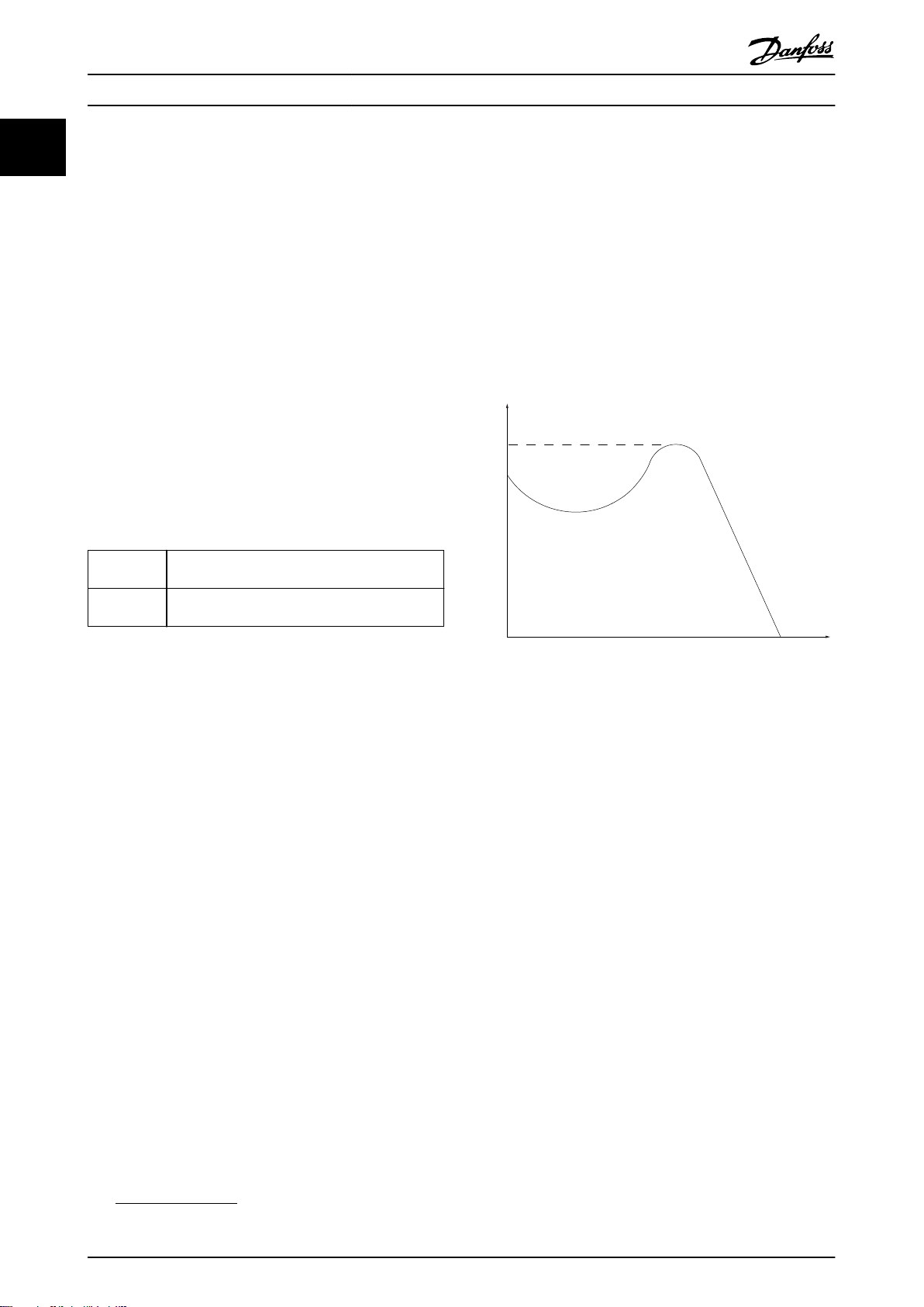
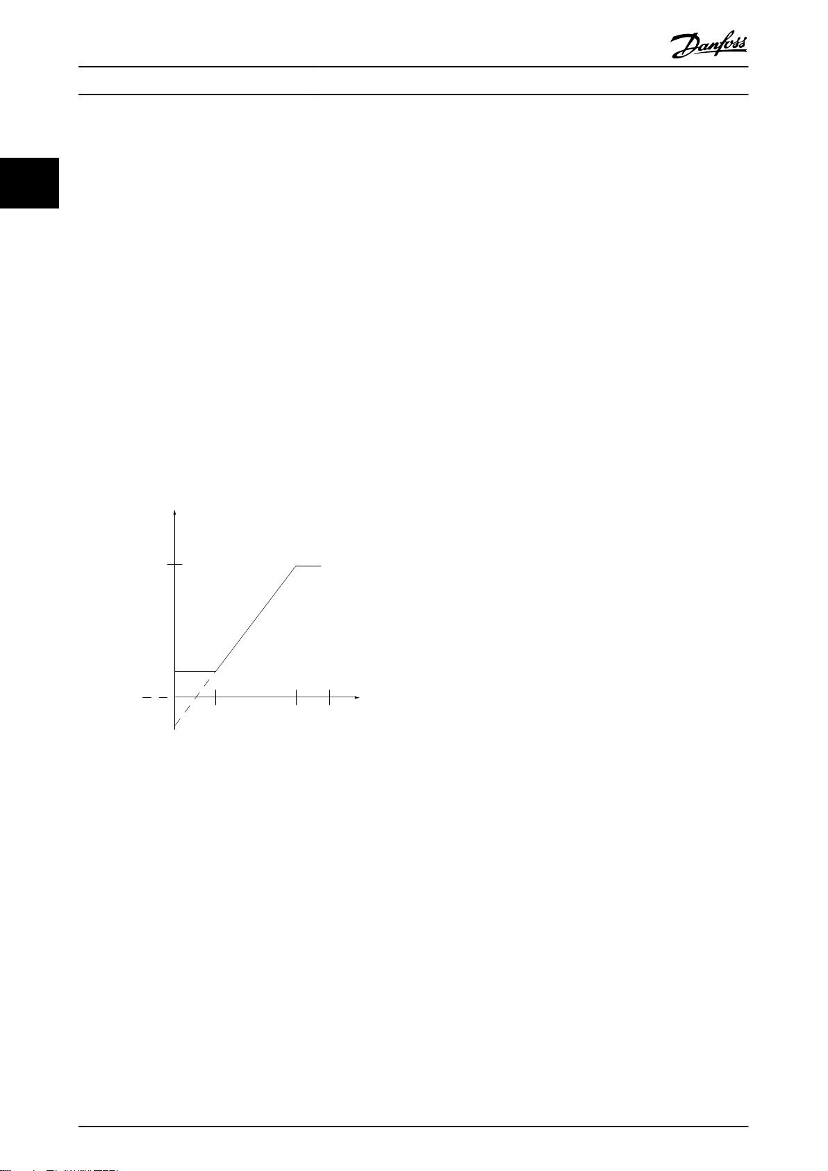
起步转矩
1.2.2 输入
控制命令
可通过 LCP 和数字输入启动和停止所连接的电机。
功能分为两组。
第 1 组中的功能比第 2 组中的功能具有更高优先级。
第 1 组 精确停止、惯性停止、精确停止和惯性停止、快
速停止、直流制动、停止和 [OFF]。
第 2 组 启动、脉冲启动、反向启动、点动、锁定输出和
[Hand On](手动启动)。
表 1.1 功能组
1.2.3 电机
电机正在运行
在输出轴上生成扭矩,电机上的速度从 0 RPM 增至最大
速度。
f
JOG
激活点动功能(通过数字端子或总线)时的电机频率。
f
M
电机频率。
f
MAX
电机最大频率。
f
MIN
电机最小频率。
f
M,N
电机额定频率(铭牌数据)。
I
M
电机电流(实际值)。
I
M,N
额定电机电流(铭牌数据)。
n
M,N
电机额定速度(铭牌数据)。
n
s
同步电机速度。
2 ×
ns=
参数
1−23 × 60s
参数
1−39
图 1.1 起步转矩
η
VLT
变频器效率被定义为输出功率和输入功率的比值。
启动 - 禁用命令
启动-禁用命令属于第 1 组的控制命令。有关详细信息,
请参阅
表 1.1
。
停止命令
停止命令属于第 1 组的控制命令。有关详细信息,请参
阅
表 1.1
。
1.2.4 参考值
模拟参考值
传输到模拟输入端 53 或 54 的信号,该值可为电压或电
流。
二进制参考值
通过串行通讯端口传输的信号。
预置参考值
定义的预置参考值,该值可在参考值的 -100% 到 +100%
范围内设置。可以通过数字端子选择的 8 个预置参考
值。可以通过总线选择的 4 个预置参考值。
脉冲参考值
传输到数字输入(端子 29 或 33)的脉冲频率信号。
6 Danfoss A/S © 03/2019 全权所有。 MG06B541
Page 9
简介 设计指南
Ref
MAX
确定 100% 满额值(通常是 10 V、20 mA)时的参考值
输入和产生的参考值之间的关系。在
Reference
Ref
中设置最大参考值。
MIN
参数 3-03 Maximum
确定 0% 值(通常是 0 V、0 mA、4 mA)时的参考值输
入和产生的参考值之间的关系。在
Reference
中设置最小参考值。
参数 3-02 Minimum
1.2.5 其他
模拟输入
模拟输入可用于控制变频器的各项功能。
模拟输入有两种类型:
电流输入: 0–20 mA 和 4–20 mA。
•
电压输入: 0–10 V DC。
•
模拟输出
模拟输出可提供 0-20 mA 或 4-20 mA 的信号。
自动电机识别 (AMA)
AMA 算法可确定相连电机处于静止状态时的电气参数。
制动电阻器
制动电阻器是一个能够吸收再生制动过程中所产生的制动
功率的模块。该再生制动功率会使直流回路电压增高,制
动斩波器可确保将该功率传输到制动电阻器。
CT 特性
恒转矩特性,用于所有应用中(如传送带、容积泵和起重
机)。
数字输入
数字输入可用于控制变频器的各项功能。
数字输出
变频器具有 2 个可提供 24 V 直流信号(最大 40 mA)
的固态输出。
ETR
电热继电器是基于当前负载及时间的热负载计算元件。其
作用是估计电机温度。
FC 标准总线
包括使用 FC 协议或 MC 协议的 RS485 总线。请参阅
参数 8-30 协议
正在初始化
如果执行初始化(
复位),变频器将恢复为默认设置。
间歇工作周期
间歇工作额定值是指一系列工作周期。每个周期包括一个
加载时段和卸载时段。操作可以是定期工作,也可以是非
定期工作。
LCP
本地控制面板是对变频器进行控制和编程的完整界面。LCP
可拆除。使用安装套件选件,可将 LCP 安装到前面板中
与变频器之间的距离不超过 3 米(9.8 英尺)的位置。
。
参数 14-22 工作模式
或 2 键组合式
GLCP
本地图形控制面板 (LCP 102) 界面用于对变频器进行控
制和编程。显示屏是图形式,面板用于显示过程值。GLCP
具有存储和复制功能。
NLCP
本地数字控制面板 (LCP 21) 界面用于对变频器进行控制
和编程。显示屏是数字式的,因此该面板用于显示过程
值。NLCP 具有存储和复制功能。
低位 (lsb)
最小有效位。
高位 (msb)
最大有效位。
MCM
Mille Circular Mil 的缩写,是美国测量电缆横截面积
的单位。1 MCM = 0.5067 mm2。
联机/脱机参数
对联机参数而言,在更改了其数据值后,改动将立即生
效。按 [OK](确定)键可激活对脱机参数所做的更改。
过程 PID
PID 控制可调节输出频率,使之与变化的负载相匹配,从
而维持所需的速度、压力和温度。
PCD
过程控制数据。
电源循环
关闭主电源,直到显示屏 (LCP) 熄灭,然后再次打开电
源。
功率因数
功率因数表示 I1 和 I
功率因数
3xUxI1cosϕ1
=
3xUxI
对于 VLT® AutomationDriveFC 360 变频器,
之间的关系。
RMS
RMS
cosϕ1
=
1,因此:
功率因数
I1xcosϕ1
=
I
RMS
=
I
I
RMS
1
功率因数表示变频器对主电源施加负载的程度。
功率因数越小,相同功率性能的 I
2
2
I
RMS
=
I
+ I
1
5
+ I
2
+ .. + I
7
2
n
就越大。
RMS
此外,功率因数越高,表明不同的谐波电流越小。
借助内置的直流线圈可获得较高的功率因数,从而将对主
电源施加的负载降到最低程度。
脉冲输入/增量编码器
一种外接式数字脉冲传感器,用于反馈电机转速信息。这
种编码器用于具有较高速度控制精度要求的应用。
RCD
漏电断路器。
设置
将参数设置保存在 2 个菜单中。可在这 2 个参数菜单之
间切换,并在保持 1 个菜单有效时编辑另一个菜单。
SFAVM
该缩写描述的是开关模式定子磁通定向的异步矢量调制。
1 1
MG06B541 Danfoss A/S © 03/2019 全权所有。 7
Page 10
简介
VLT® AutomationDrive FC 360
11
滑差补偿
变频器通过提供频率补偿(根据测量的电机负载)对电机
滑差进行补偿,以保持电机速度的基本恒定。
智能逻辑控制 (SLC)
SLC 是一系列由用户定义的操作,当智能逻辑控制器判断
相关的用户定义的事件为“真”时(
设置
),将执行这些操作。
STW
状态字。
THD
总谐波失真表明了谐波失真的总体影响。
热敏电阻
温控电阻器被安装在监测温度的地方(变频器或电机)。
跳闸
当变频器遭遇过电压等故障或为了保护电机、过程或机械
装置时所进入的状态。只有当故障原由消失后,才能重新
启动,跳闸状态可通过激活复位来取消,有时候还可通过
编程自动复位来取消。请勿因个人安全而使用跳闸。
跳闸锁定
跳闸锁定是当变频器在故障状态下进行自我保护并且需要
人工干预时(例如,变频器的输出端发生短路所导致的跳
闸锁定)所进入的状态。只有通过切断主电源、消除故障
原因并重新连接变频器,才可以取消锁定性跳闸。在通过
激活复位或自动复位(通过编程来实现)取消跳闸状态之
前,禁止重新启动。请勿因个人安全而使用跳闸。
VT 特性
可变转矩特性用于泵和鼓风机。
+
VVC
与标准电压/频率比控制相比,电压矢量控制 (VVC+) 可
在速度参考值发生改变或与负载转矩相关时提高动力特性
和稳定性。
60° AVM
60°
请参阅开关模式
安全事项
1.3
异步矢量调制。
参数组 13-** 编程
警告
只要变频器与主电源相连,它就会带有危险电压。如果电
机、变频器或现场总线安装不当,则可能导致死亡、严重
人身伤害或设备损坏。因此,必须遵守本手册中的规定以
及国家和地方的条例和安全规定。
安全规定
1. 在执行维修工作之前,请始终断开变频器主电
源。检查主电源确是否已断开,进行观察并持续
表 1.2
中指定的放电时间后再拆除电机和主电
源。
2. LCP 上的 [Off/Reset](停止/复位)键不能断
开主电源,因此不得用作安全开关。
3. 将设备正确接地,防止使用者接触到电源电压,
对电机采取过载保护措施。这些措施应符合国家
和地方法规的具体规定。
4. 在出厂设置的参数中未包括对电机的过载保护。
如果需要使用此功能,请将
保护
设置为
告 1
。
5. 进行负载共享(连接直流中间回路)时,变频器
的输入电源不止 L1、L2 和 L3。在开始修理工
作前,确保所有电源输入端均已断开,并等待一
段时间后再开始修理。
意外启动警告
1. 当变频器与主电源相连时,可采用数字指令、总
线指令、参考值、或者本地停止使电动机停止。
如果出于人身安全方面(例如,在意外启动之后
接触运转中的机器部件而造成人身伤害的风险)
的考虑而必须保证不会发生意外启动现象的话,
这些停止功能是不够的。在这些情况下,断开主
电源。
2. 电机可以在设置参数的同时启动。如果这意味着
可能降低人身安全,则必须防止电机启动,比
如,通过安全断开电机连接。
3. 连接了主电源的电机在停止之后可能会在这些情
况下启动:变频器的电气设施发生故障时、通过
临时过载,或者在供电电网或电机连接得以修
复。如果为人身安全起见而必须防止意外启动,
则变频器的正常停止功能是不够的。在这些情况
下,断开主电源。
4. 来自变频器,或者变频器内部的控制信号很少会
错误激活、延迟或完全无法启动。在安全至关重
要的情况下,比如控制起重应用的电磁制动功能
时,不得单独依赖这些控制信号。
[4] ETR 跳闸 1
参数 1-90 电动机热
或
[3] ETR 警
警告
高电压
即使设备已断开与主电源的连接,触碰电气部件也可能会
导致生命危险。
确保所有电压输入都已断开,包括负载共享(直流中间电
路的连接),以及用于借能运行的电动机连接。
安装了变频器的系统必须(如果需要的话)根据有效的安
全规范(例如,有关机械工具的法律、防止出现事故的规
范等)配备附加的监控和保护设备。允许通过操作软件修
改变频器。
注意
机器构建商/集成商应确定各种危险情况并负责考虑采取必
要的预防措施。可能还包含附加的监控和防护设备,但务
必符合相关的国家安全规范,比如有关机械工具的法律以
及事故预防规范。
8 Danfoss A/S © 03/2019 全权所有。 MG06B541
Page 11
简介 设计指南
警告
放电时间
即使变频器未上电,变频器直流回路的电容器可能仍有
电。即使警告指示灯熄灭,也可能存在高压。在切断电源
后,如果在规定的时间结束之前就执行维护或修理作业,
则可能导致死亡或严重伤害。
停止电机。
•
断开交流主电源、远程直流电源(包括备用电
•
池)、UPS 以及与其它变频器的直流回路连接。
断开或锁定永磁电机。
•
请等待电容器完全放电。最短等待时间在
•
表 1.2
中指定,也可在变频器顶部的产品标签
上看到。
在执行任何维护或修理作业之前,使用适当的电
•
压测量设备,以确保电容器已完全放电。
电压
[V]
380–480
380–480
表 1.2 放电时间
处理说明
1.4
功率范围
[kW (hp)]
0.37–7.5 kW
(0.5–10 hp)
11–75 kW
(15–100 hp)
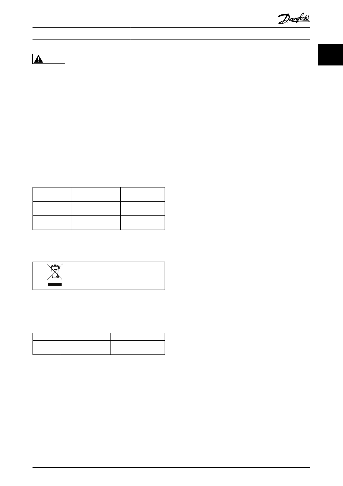
装有电子元件的设备不能与生活垃圾一起
处理。
必须按照地方和现行法规,将其作为电气
和电子废弃物单独回收。
最短等待时间
(分钟)
4
15
1.6 批准和认证
变频器按照本部分所述的指令要求进行设计。
有关认证和证书的详情,请访问下载区:
www.danfoss.com/fc360
.
1.6.1 CE 标志
CE 标志 (Conformité Européenne) 表示该产品制造商遵
守所有适用的 EU 指令。
适用于变频器设计和制造的 EU 指令如下:
低电压指令。
•
EMC 指令。
•
机械指令(适用于带有集成的安全功能的设
•
备)。
CE 标志旨在消除 ECU 中 EC 和 EFTA 成员国之间自由贸
易的技术壁垒。CE 标志并不监管产品的质量。从 CE 标
志中无法获得技术规格信息。
1.6.2 低电压指令
变频器被归类为电子元件,必须根据低电压指令通过 CE
认证。该指令适用于电压范围为 50–1000 V 交流和
75–1500 V 直流的所有电气设备。
该指令规定,设备设计必须确保设备在正确安装、维护和
按预期方式使用情况下不会危及人员和家畜的安全和健康
并保护财产。DanfossCE 标志表示符合低电压指令,
Danfoss 还可根据要求提供符合声明。
1 1
1.5 文档和软件版本
我们将对本手册定期进行审核和更新。欢迎任何改进建
议。
版本 备注 软件版本
MG06B5xx 因出现新的硬件和软件
版本而更新。
1.8x
1.6.3 EMC 指令
电磁兼容性 (EMC) 表示设备部件之间的电磁干扰不会影
响它们的性能。EMC 指令 2014/30/EU 的基本保护要求规
定,产生电磁干扰 (EMI) 或其运行可能受 EMI 影响的设
备在设计时必须限制电磁干扰的产生,并且在正确安装、
维护和按预期方式使用情况下应具备适度的抗电磁干扰等
级。
变频器可用作独立设备或更复杂系统的组成部分。无论哪
种情况,设备上都必须带有 CE 标志。系统不一定带有
CE 标志,但必须符合 EMC 指令的基本保护要求。
MG06B541 Danfoss A/S © 03/2019 全权所有。 9
Page 12
130BA870.10
130BA809.10
130BA810.10
130BA810.10
130BA810.10
130BA826.10
130BA826.10
产品概述
VLT® AutomationDrive FC 360
2 产品概述
22
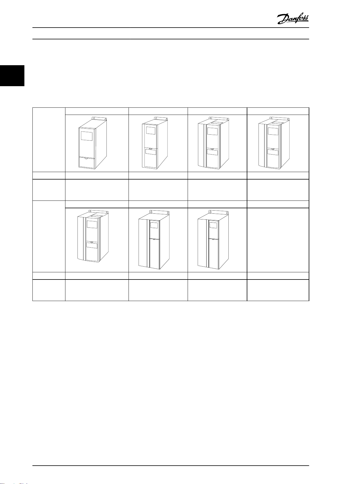
2.1 机箱规格概述
机箱规格取决于功率范围。
机箱规格 J1 J2 J3 J4
机箱保护 IP20 IP20 IP20 IP20
高额定过载功
率 - 最高
160% 过载
机箱规格 J5 J6 J7
0.37–2.2 kW/0.5–3 hp
1)
(380–480 V)
3.0–5.5 kW/4.0–7.5 hp
(380–480 V)
7.5 kW/10 hp (380–480
V)
11–15 kW/15–20 hp
(380–480 V)
机箱保护 IP20 IP20 IP20
高额定过载功
率 - 最高
160% 过载
表 2.1 机箱规格
18.5–22 kW/25–30 hp
1)
(380–480 V)
30–45 kW/40–60 hp
(380–480 V)
55–75 kW/75–100 hp
(380–480 V)
1) 规格 11–75 kW (15–100 hp) 正常过载类型: 过载 110% 持续 1 分钟。
规格 0.37–7.5 kW (0.5–10 hp) 高过载类型: 过载 160% 持续 1 分钟。
规格 11–22 kW (15–30 hp) 高过载类型: 过载 150% 持续 1 分钟。
规格 30–75 kW (40–100 hp) 高过载类型: 过载 150% 持续 1 分钟。
10 Danfoss A/S © 03/2019 全权所有。 MG06B541
Page 13
130BC438.19
3 phase
power
input
Switch mode
power supply
Motor
Interface
(PNP) = Source
(NPN) = Sink
ON=Terminated
OFF=Open
Brake
resistor
91 (L1)
92 (L2)
93 (L3)
PE
50 (+10 V OUT)
53 (A IN)
54 (A IN)
55 (COM A IN/OUT)
0/4-20 mA
12 (+24 V OUT)
33 (D IN)
18 (D IN)
20 (COM D IN)
10 V DC
15 mA 100 mA
+ - + -
(U) 96
(V) 97
(W) 98
(PE) 99
(P RS485) 68
(N RS485) 69
(COM RS485) 61
0V
5V
S801
RS485
RS485
03
+10 V DC
0/4-20 mA
0-10 V DC
24 V DC
02
01
05
04
250 V AC, 3 A
24 V (NPN)
0 V (PNP)
0 V (PNP)
24 V (NPN)
19 (D IN)
24 V (NPN)
0 V (PNP)
27 (D IN/OUT)
24 V
0 V
0 V (PNP)
24 V (NPN)
0 V
24 V
29 (D IN/OUT)
24 V (NPN)
0 V (PNP)
0 V (PNP)
24 V (NPN)
32 (D IN)
31 (D IN)
95
P 5-00
21
ON
(+UDC) 89
(BR) 81 5)
24 V (NPN)
0 V (PNP)
0-10 V DC
(-UDC) 88
RFI
3)
0 V
250 V AC, 3 A
Relay 1
1)
Relay 2 2)
4)
06
42 (A OUT)
45 (A OUT)
Analog
output
0/4-20 mA
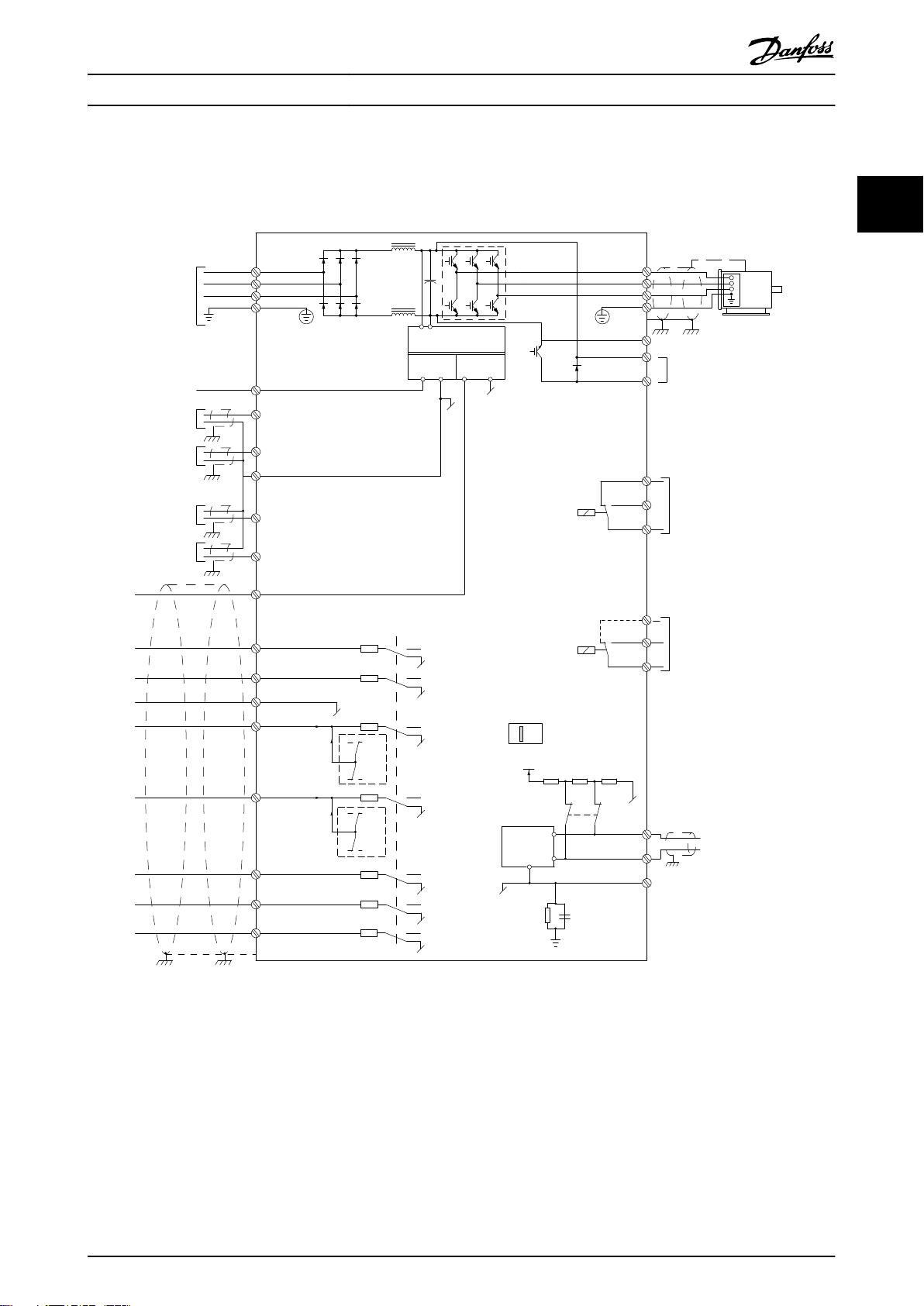
产品概述 设计指南
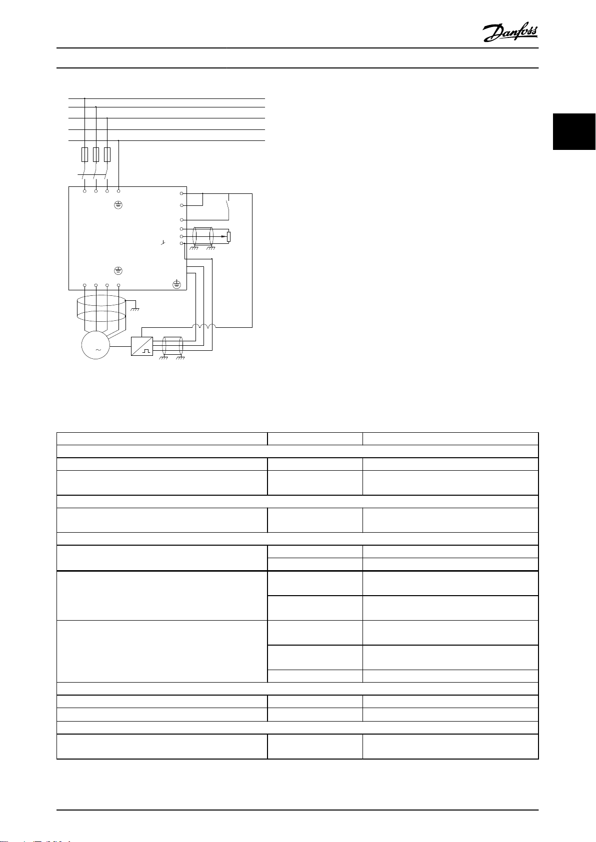
2.2 电气安装
本节介绍如何连接变频器。
2 2
图 2.1 基本接线示意图
A=模拟,D=数字
1) J1–J5 上配有内置制动斩波器。
2) 对于 J1-J3,继电器 2 为两触点极;对于 J4-J7,继电器 2 为 3 触点。J4-J7 的 继电器 2 上的端子 4、5、6 的常
开/常闭逻辑与继电器 1 相同。继电器在 J1-J5 中为可插拔式,在 J6-J7 中为固定式。
3) J1–J5 中配有单个直流电抗器; J6–J7 中配有两个直流电抗器。
4) 开关 S801(总线端子)可用于端接 RS485 端口(端子 68 和 69)。
5) J6–J7 中无 BR。
MG06B541 Danfoss A/S © 03/2019 全权所有。 11
Page 14
e30bf228.11
L1
L2
L3
PE
PE
u
v
w
2
1
3
5
16
17
18
14
12
8
7
10
9
4
11
13
4
6
15
90
4
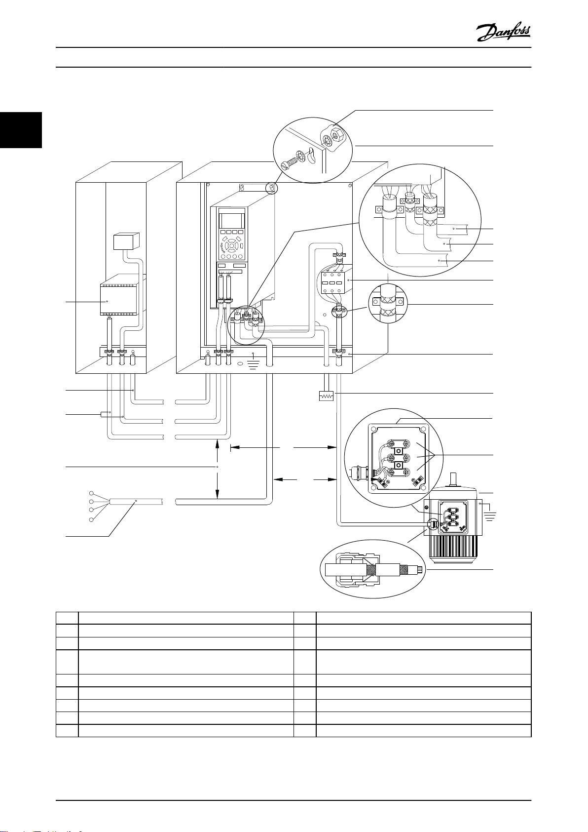
产品概述
VLT® AutomationDrive FC 360
22
1 PLC 10 主电源电缆(非屏蔽)
2
最小横截面积 16 mm2 (6 AWG) 的均衡电缆
3 控制电缆 12 已剥开的电缆绝缘层
4 控制电缆、电机电缆和主电源电缆之间至少保持 200 毫米
(7.87 英寸)的距离。
5 主电源电压 14 制动电阻器
6 裸(未涂漆)表面 15 金属箱
7 星形垫圈 16 电机接头
8 制动电缆(屏蔽) 17 电机
9 电机电缆(屏蔽) 18 EMC 电缆夹
图 2.2 典型电气连接
11 输出接触器等。
13 通用接地母线。请遵循国家和地方有关机柜接地的要求。
12 Danfoss A/S © 03/2019 全权所有。 MG06B541
Page 15
130BC500.10
FC 1
FC 1
FC 2
FC 2
FC 3
FC 3
PE
PE
产品概述 设计指南
警告
设备危险
旋转主轴和电气设备均有相当的危险性。为设备通电时应
采取预防措施,以防电气危险。所有电气作业均须符合国
家和地方电气法规。必须由受过培训并且具备资质的人员
来执行安装、启动和维护。如果不遵守这些指导原则,将
可能导致死亡或严重伤害。
警告
线路隔离
使用 3 根单独的金属线管或单独的屏蔽电缆布置输入电
源、电动机和控制系统的线路,以实现高频噪声隔离。如
果不隔离电源、电动机和控制线路,将可能影响变频器和
关联设备的性能。
对来自多台变频器的电机电缆进行单独布置。如果将输出
电动机电缆一起布置,感生电压可能会对设备电容器进行
充电,哪怕设备处于关闭并被加锁的状态,也会如此。如
果未单独布置电机输出电缆或使用屏蔽电缆,则可能导致
死亡或严重伤害。
2 2
单独布置输出电机电缆。
•
使用屏蔽电缆。
•
同时锁定所有变频器。
•
线型和额定值
所有接线都必须符合国家和地方法规中关于横截
•
面积和环境温度的要求。
Danfoss 建议,所有电力连接均须使用最低额定
•
温度为 75 °C (167 °F) 的铜线来完成。
有关建议的线缆规格,请参阅
•
章 4 规格
。
图 2.3 接地原理
警告
感生电压
对来自多台变频器的输出电动机电缆进行单独布置。如果
将输出电动机电缆一起布置,感生电压可能会对设备电容
器进行充电,哪怕设备处于关闭并被加锁的状态,也会如
此。如果不单独布置电动机输出电缆,将可能导致死亡或
严重伤害。
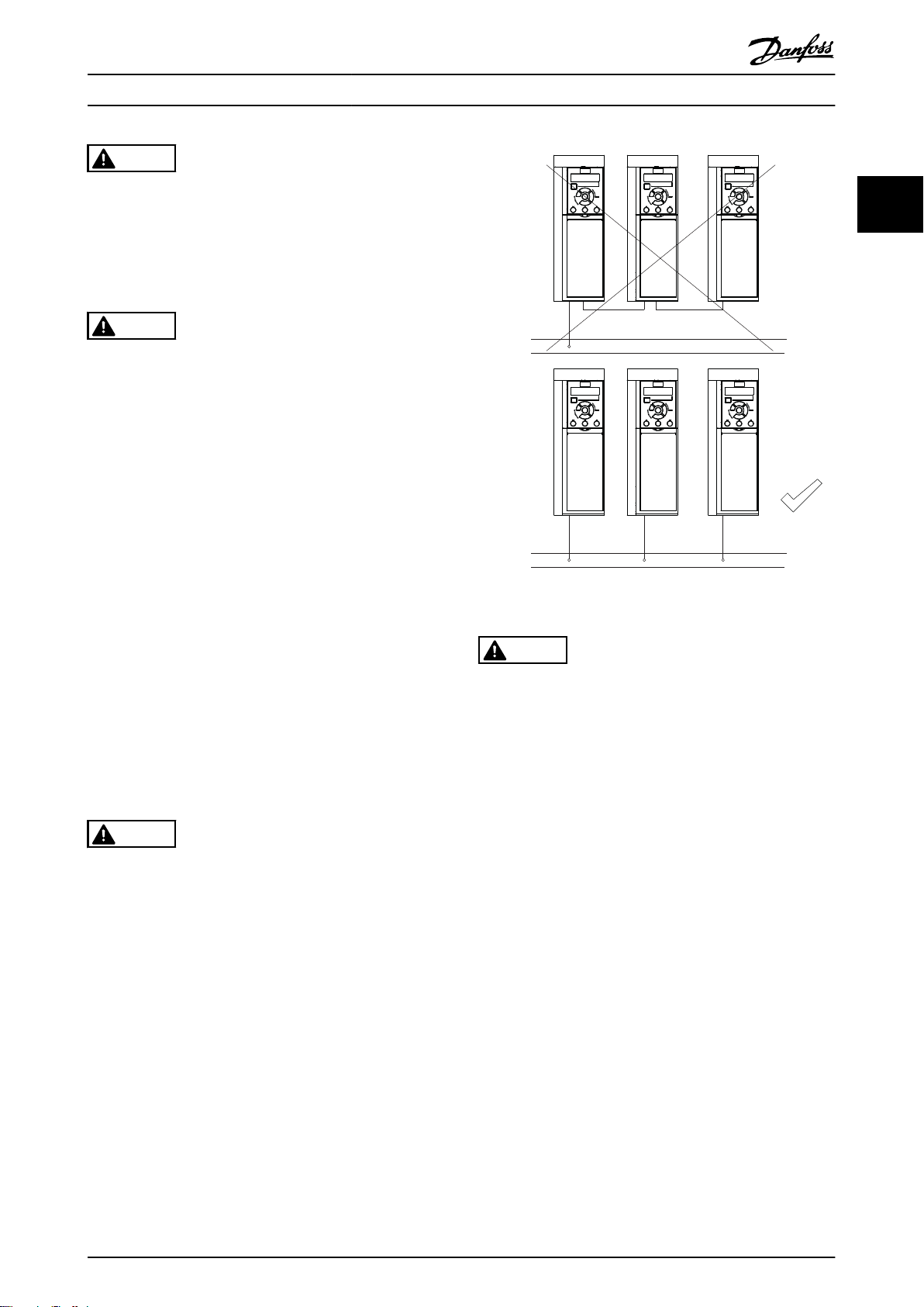
2.2.1 接地要求
系统为电动机线路提供了接地线夹(请参阅
警告
接地危险!
为了保护操作人员的安全,请务必按照国家和地方电气法
规以及本手册说明,由正规的电气装置安装技师将变频器
正确接地。接地电流高于 3.5 mA。如果不将变频器正确
接地,将可能导致死亡或严重伤害。
对于接地电流高于 3.5 mA 的设备,必须对其进
•
•
•
•
•
•
•
行正确的保护性接地。有关详细信息,请参阅
章 2.8 接地漏电电流
输入电源、电动机电源和控制系统的线路须采用
专门的接地线。
为了正确接地,请使用设备上提供的线夹。
请勿以“菊花链”方式将一台变频器的地线连接
至另一变频器的地线上(请参阅
地线连接应尽可能短
为了减小电气噪声,请使用高集束线。
请遵守电机制造商的接线要求。
。
图 2.3
)。
请勿在变频器和电动机之间安装功率因数修正电
•
容器。
请勿在变频器和电动机之间连接启动或变极设
•
备。
请遵守电机制造商的接线要求。
•
所有变频器都必须使用单独的电力输入源,也可
•
以使用接地参考电力线路。如果由独立的主电源
( IT 主电源或浮动三角形连接)或带有接地脚
(接地三角形连接)的 TT/TN-S 主电源供电,
则将
参数 14-50 射频干扰滤波器
“关”(机箱规格 J6-J7)或卸除 RFI 螺钉
(机箱规格 J1-J5)。根据 IEC 61800-3 的规
定,在设为“关”时,机架与中间电路之间的内
置射频干扰电容会被隔离,以免损坏中间电路和
降低地容电流。
请勿在 IT 主电源内的变频器和电动机之间安装
•
开关。
图 2.4
设置为
)。
MG06B541 Danfoss A/S © 03/2019 全权所有。 13
Page 16
130BC501.10
01
02 03
04
05
130BD648.11
130BC504.11
42 45
12
18
19
27
29
31
32
33
20
50
53
54
55
130BC505.12
产品概述
VLT® AutomationDrive FC 360
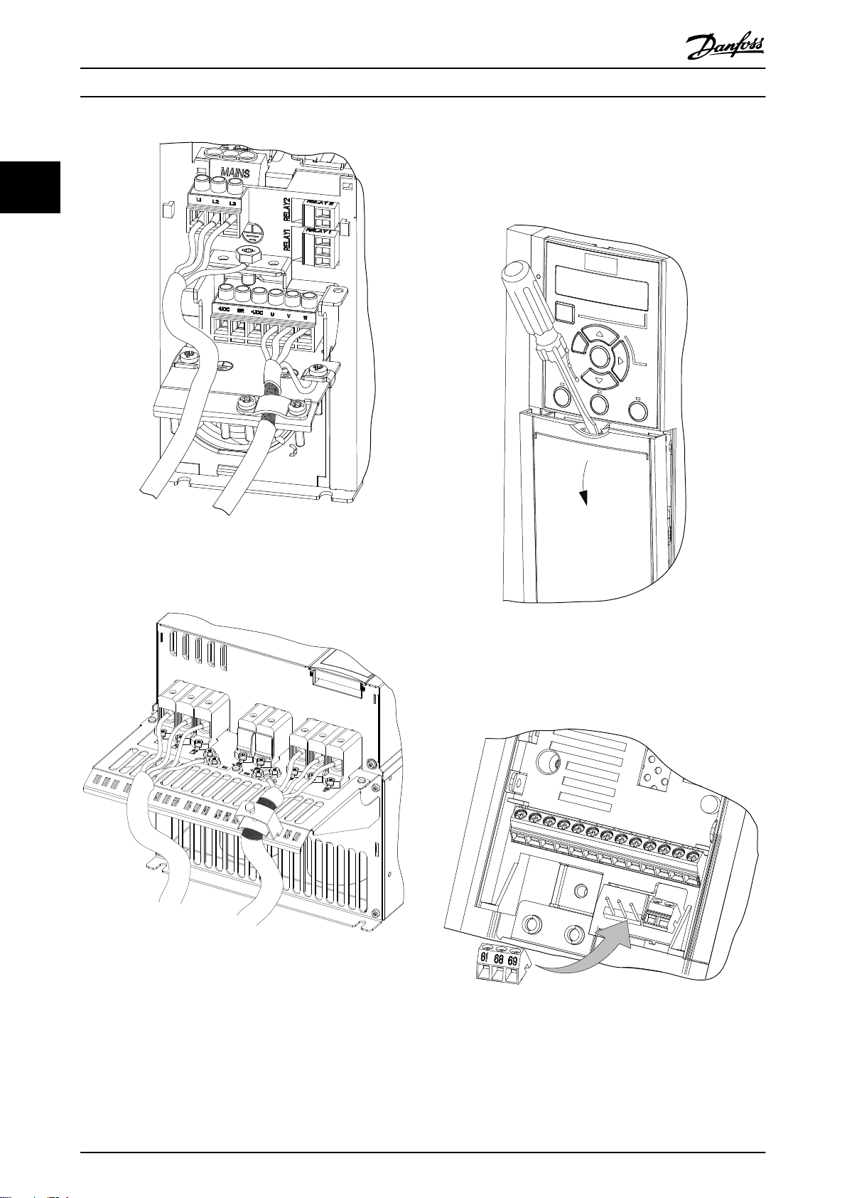
2.2.2 控制线路
访问
22
用螺丝刀拆下盖板。请参阅
•
图 2.6
。
图 2.4 J1–J5 型机箱的主电源接线、电机接线和接地(以
J2 为例)
图 2.6 J1-J7 机箱规格的控制线路检视
控制端子类型
图 2.7
显示了变频器的所有控制端子。在
端子功能及其默认设置进行了总结。
表 2.2
中对
图 2.5 J6–J7 型机箱的主电源接线、电机接线和接地(以
J7 为例)
图 2.4
例示出 J1–J5 型机箱的主电源输入接线、电机
接线和接地。
入接线、电机接线和接地。实际配置可能随设备类型和选
配设备的不同而存在差异。
图 2.5
例示出 J6–J7 型机箱的主电源输
图 2.7 控制端子位置
有关端子额定值信息,请参阅
章 4.2 一般规范
。
14 Danfoss A/S © 03/2019 全权所有。 MG06B541
Page 17

产品概述 设计指南
端子 参数 默认设置 说明
数字 I/O、脉冲 I/O、编码器
24V 直流供电电
压。所有 24 V
12 – +24 V 直流
18
19
31
32
33
27
29
20 –
参数 5-10 端子
18 数字输入
参数 5-11 端子
19 数字输入
参数 5-16 端子
31 数字输入
参数 5-14 端子
32 数字输入
参数 5-15 端子
33 数字输入
参数 5-12 端子
27 数字输入
参数 5-30 端子
27 数字输出
参数 5-13 端子
29 数字输入
参数 5-31 端子
29 数字输出
模拟输入/输出
[8] 启动
[10] 反向
[0] 无功能 数字输入
[0] 无功能
[0] 无功能
DI [2] 惯
性停车
DO [0] 无
功能
DI [14] 点
动
DO [0] 无
功能
数字输入的公共
参
42
数 6-91 Terminal
[0] 无功能
42 Analog Output
参
45
数 6-71 Terminal
[0] 无功能
45 Analog Output
50 – +10 V 直流
53 6-1* 参数组 参考值
54 6-2* 参数组 反馈
负载的最大输出
电流为 100
mA。
数字输入。
数字输入,24 V
编码器。端子
33 可用作脉冲
输入。
可以选择用作数
字输入、数字输
出或脉冲输出。
默认设置为数字
输入。
端子 29 可用于
脉冲输入。
端子,0 V 电压
针对 24 V 电
源 。
可编程模拟输
出。在最大阻抗
为 500 Ω 的情
况下,模拟信号
为 0-20 mA 或
4-20 mA 也可配
置为数字输出。
10 V DC 模拟供
电电压。最大电
流为 15 mA,常
用于电位计或热
敏电阻。
模拟输入。可选
择电压或电流。
端子 参数 默认设置 说明
用于屏蔽层的集
成 RC 滤波器。
61 –
68 (+) 8-3* 参数组
69 (-) 8-3* 参数组
继电器
01, 02,
03
04, 05,
06
表 2.2 端子说明
5-40 [0] [0] 无功能
5-40 [1] [0] 无功能
仅应在遇到 EMC
问题时才将其连
接到屏蔽层。
RS485 接口。控
制卡终端电阻开
关
C 型继电器输
出。这些继电器
的具体位置因变
频器的配置和尺
寸而异。可用于
交流或直流电压
及电阻性或电感
性负载。
J1-J3 机箱内的
继电器 2 为 2
触点,只有
04、05 端子可
用
控制端子功能
变频器的功能由收到的控制输入信号控制。
对于每个端子,在与它相关的参数中根据它所支
•
持的功能对它进行设置。
确认是否已对控制端子进行了与相关功能有关的
•
正确设置。请参阅快速指南中的
编程
一章了解有关访问参数和编程的详细信
本地控制面板和
息。
默认的端子设置将启动变频器并使其在典型工作
•
模式下工作。
使用屏蔽控制电缆
为保证尽可能好的高频电缆接触,大多数情况下的首选方
法都是在控制电缆和串行通讯电缆两端用屏蔽夹加以固
定。
如果变频器和 PLC 之间的大地电势不同,可能产生干扰
整个系统的电噪声。通过在距控制电缆尽可能近的位置安
装一条均衡电缆,可解决此问题。该电缆的最小横截面
积: 16 mm2 (6 AWG)。
2 2
55 –
串行通讯
MG06B541 Danfoss A/S © 03/2019 全权所有。 15
模拟输入的公共
端子
Page 18
1
2
PE
FC
PE
PLC
130BB922.12
PE PE
<10 mm
100nF
FC
PE
PE
PLC
<10 mm
130BB609.12
PE
FC
PE
FC
130BB923.12
PE PE
69
68
61
69
68
61
1
2
<10 mm
PE
FC
PE
FC
130BB924.12
PE PE
69
69
68
68
1
2
<10 mm
产品概述
VLT® AutomationDrive FC 360
2.3 控制结构
2.3.1 控制原理
22
变频器将主电源交流电压整流为直流电压。然后将该直流
电压转换成幅值和频率均可变的交流电流。
1
最小 16 mm2 (6 AWG)
2 均衡电缆
电机输入的电压/电流和频率均可变,从而可使三相标准交
流电机和永磁同步电机实现无级变速控制。
图 2.8 两端安装屏蔽夹
50/60 Hz 接地回路
使用很长的控制电缆时,可能会形成接地回路。为了消除
接地回路,请用 1 个 100 nF 电容器将屏蔽层的一端接
地(引线应尽可能短)。
图 2.9 与 100 nF 电容的连接
避免串行通讯的 EMC 噪声
该端子通过一个内部 RC 回路接地。为减小导体之间的相
互干扰,请使用双绞电缆。显示了建议的方法
1
最小 16 mm2 (6 AWG)
2 均衡电缆
图 2.10 双绞线
图 2.10
。
或者也可以省去与端子 61 的连接。
1
最小 16 mm2 (6 AWG)
2 均衡电缆
2.3.2 控制模式
变频器可以控制电机主轴的速度或转矩。控制类型取决于
对
参数 1-00 配置模式
速度控制
速度控制有 2 种类型:
开环速度控制,此模式不需要来自电动机的任何
•
反馈(无传感器)。
速度闭环 PID 控制,要求向某个输入提供速度
•
反馈。同开环速度控制相比,经过适当优化的闭
环速度控制将具有更高的精确性。
在
参数 7-00 速度 PID 反馈源
反馈的输入。
转矩控制
转矩控制功能用于下述应用:电动机输出轴上的转矩以张
力控制形式来控制相关应用。可在
中选择转矩控制。转矩设置是通过设置某个由模拟、数字
或总线控制的参考值来实现的。在采用转矩控制时,建议
执行完整 AMA 过程,因为正确的电动机数据对于获得最
佳性能非常重要。
VVC+ 模式下的闭环。此功能在轴呈中低程度动
•
态变化的应用中使用,可在所有 4 个象限中以
及所有电动机速度下提供优异性能。必须提供速
度反馈信号。建议使用 MCB102 选件卡。确保编
码器分辨率至少为 1024 PPR,且编码器的屏蔽
电缆接地良好,因为速度反馈信号的准确性很重
要。调整
最佳速度反馈信号。
VVC+ 模式下的开环。该功能用于机械可靠性应
•
用,但精度有限。开环转矩功能在两个方向有
效。转矩是基于变频器内部的电流测量值来计算
的。
速度/转矩参考值
这些控制值的参考可以是单个参考值,也可以是不同参考
值(包括百分比形式的参考值)的叠加。参考值的处理方
章 2.4 参考值处理
法在
的设置。
中可选择用作速度 PID
参数 1-00 配置模式
参数 7-06 速度 PID 低通滤波
中详细介绍。
以获取
图 2.11 双绞电缆(无端子 61)
16 Danfoss A/S © 03/2019 全权所有。 MG06B541
Page 19
130BD974.10
L2 92
L1 91
L3 93
M
U 96
V 97
W 98
RFI switch
Inrush
R+
82
Load sharing -
88(-)
R81
Brake resistor
Load sharing +
89(+)
Load sharing -
Load sharing +
L2 92
L1 91
L3 93
89(+)
88(-)
Inrush
R inr
M
U 96
V 97
W 98
P 14-50
130BD975.10
产品概述 设计指南
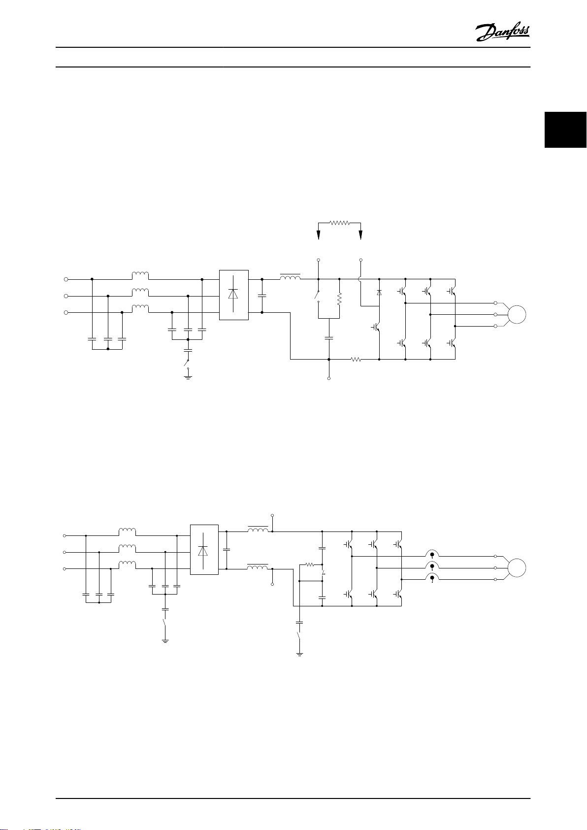
2.3.3 FC 360 控制原理
VLT® AutomationDrive FC 360 是一款用于变速应用的通用变频器。其控制原理基于 Voltage Vector Control+。
0.37–22 kW (0.5–30 hp)
FC 360 0.37–22 kW (0.5–30 hp) 变频器可处理功率高达 22 kW 的异步电机和永磁同步电机。
FC 360 0.37–22 kW (0.5–30 hp) 变频器的电流传感原理基于直流回路中电阻器的电流测量值。接地故障保护和短路
行为由同一电阻器处理。
图 2.12 FC 360 0.37–22 kW (0.5–30 hp) 的控制图
2 2
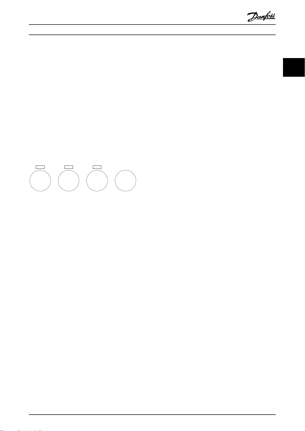
30–75 kW (40–100 hp)
FC 360 30–75 kW (40–100 hp) 变频器只能处理异步电机。
FC 360 30–75 kW (40–100 hp) 变频器的电流传感原理基于电机相中的电流测量值。
FC 360 30–75 kW (40–100 hp) 变频器上的接地故障保护和短路行为由电机相中的 3 个电流电阻器处理。
图 2.13 FC 360 30–75 kW (40–100 hp) 的控制图
MG06B541 Danfoss A/S © 03/2019 全权所有。 17
Page 20

+
_
+
_
S
S
Cong. mode
Ref.
Process
P 1-00
High
+f max.
Low
-f max.
P 4-12
Motor speed
low limit (Hz)
P 4-14
Motor speed
high limit (Hz)
Motor
controller
Ramp
Speed
PID
P 7-20 Process feedback
1 source
P 7-22 Process feedback
2 source
P 7-00 Speed PID
feedback source
P 1-00
Cong. mode
P 4-19
Max. output freq.
-f max.
Motor
controller
P 4-19
Max. output freq.
+f max.
P 3-**
P 7-0*
130BD371.10
产品概述
VLT® AutomationDrive FC 360
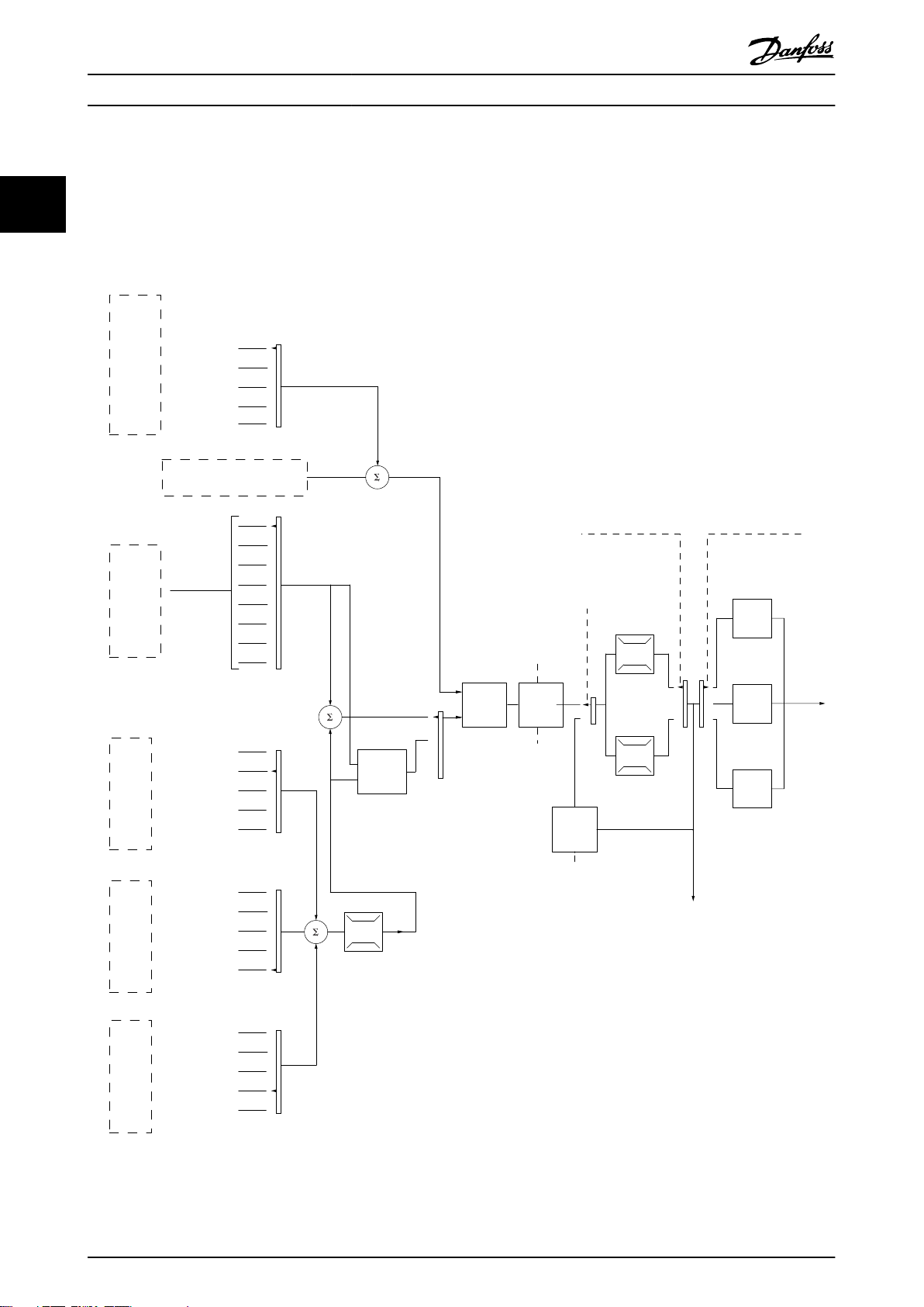
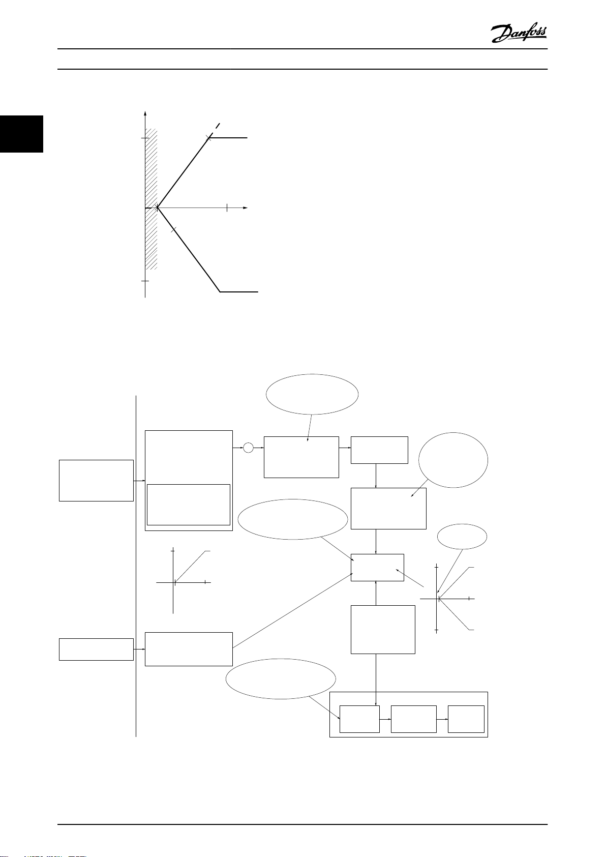
2.3.4
VVC+中的控制结构
22
图 2.14 VVC+ 开环和闭环配置下的控制结构
在
图 2.14
所显示的配置中,
参数 1-01 电动控制原理
设为
[1] VVC
收到了参考值处理系统的最终参考值后,首先会对最终参考值进行加减速限制和速度限制,然后才将它发送给电机控制。
之后,电机控制的输出便会受到频率上限的限制。
+
,
参数 1-00 配置模式
设为
[0] 开环。
在
如果
参数 1-00 配置模式
制。速度 PID 控制参数位于
频率极限的限制)。
参数 1-00 配置模式
在
参数位于以下
参数组中:7-2* 过程控制器 反馈
中选择
设为
[1] 闭环速度
,则结果参考值在经过加减速限制和速度限制后,传递给速度 PID 控
参数组 7-0*速度 PID 控制器
[3] 过程
可使用过程 PID 控制在受控应用中对速度或压力进行闭环控制。过程 PID
和
。从“速度 PID 控制”中产生的参考值将发送给电机控制(受
7-3* 过程 PID 控制器。
18 Danfoss A/S © 03/2019 全权所有。 MG06B541
Page 21
e30bp046.12
Hand
On
Off
Auto
On
Reset
产品概述 设计指南
2.3.5
本变频器的特点是具有一体化的电流限制控制单元。当电机电流继而转矩超过
电时转矩极限 和参数 4-18 电流极限
当变频器在电机运行或发电运行中达到电流极限时,变频器会尝试尽快降低到预置转矩极限以下,同时不使电机失控。
VVC+ 模式下的内部电流控制
参数 4-16 电动时转矩极限、参数 4-17 发
中设置的转矩限值时,将激活此功能。
2.3.6 本地 [Hand On](手动启动)和远程 [Auto On](自动启动)控制
可以通过本地控制面板 (LCP) 以手动方式运行变频器,也可以借助模拟/数字输入或串行总线远程运行变频器。
按 LCP 上的 [Hand On](手动启动)和 [Off/Reset](停止/复位)键可启动和停止变频器。需要设置:
参数 0-40 LCP 的 [Hand On]键
•
参数 0-44 LCP 的 [Off/Reset] (停止/复位)键
•
参数 0-42 LCP 的 [Auto on]键
•
当端子设置为
图 2.15 LCP 控制键
“复位”
时,可通过 [Off/Reset](停止/复位)键或数字输入将报警复位。
.
.
.
2 2
不论
参数 1-00 配置模式
在关机时将恢复本地参考值。
中的设置为何,本地参考值都将强制使配置模式变为开环。
MG06B541 Danfoss A/S © 03/2019 全权所有。 19
Page 22
No function
Analog ref.
Pulse ref.
Local bus ref.
Preset relative ref.
Preset ref.
Local bus ref.
No function
Analog ref.
Pulse ref.
Analog ref.
Pulse ref.
Local bus ref.
No function
Local bus ref.
Pulse ref.
No function
Analog ref.
Input command:
Catch up/ slow down
Catchup Slowdown
value
Freeze ref./Freeze output
Speed up/ speed down
ref.
Remote
Ref. in %
-max ref./
+max ref.
Scale to
Hz
Scale to
Nm
Scale to
process
unit
Relative
X+X*Y
/100
DigiPot
DigiPot
DigiPot
max ref.
min ref.
DigiPot
D1
P 5-1x(15)
Preset '1'
External '0'
Process
Torque
Speed
open/closed loop
(1)
(2)
(3)
(4)
(5)
(6)
(7)
(0)
(0)
(1)
Relative scaling ref.
P 3-18
Ref.resource 1
P 3-15
Ref. resource 2
P 3-16
Ref. resource 3
P 3-17
200%
-200%
Y
X
-100%
100%
%
%
Ref./feedback range
P 3-00
Conguration mode
P 1-00
P 3-14
±100%
130BD374.10
P 16-01
P 16-02
P 3-12
P 5-1x(21)/P 5-1x(22)
P 5-1x(28)/P 5-1x(29)
P 5-1x(19)/P 5-1x(20)
P 3-04
Freeze ref.
&
increase/
decrease
ref.
Catch up/
slow
down
P 3-10
产品概述
VLT® AutomationDrive FC 360
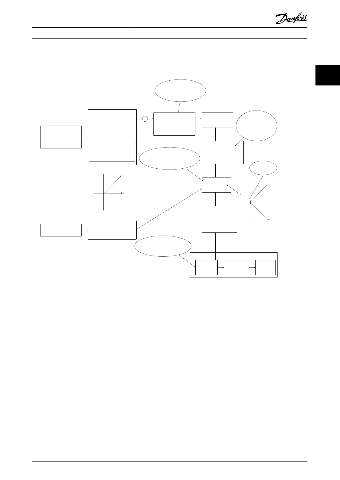
2.4 参考值处理
本地参考值
22
当变频器在 [Hand On](手动)按钮处于活动状态的情况下工作时,本地参考值将有效。通过 [▲]/[▼] 和 [◄/[►] 调
整参考值。
远程参考值
图 2.16
显示了用于计算远程参考值的参考值处理系统。
图 2.16 远程参考值
20 Danfoss A/S © 03/2019 全权所有。 MG06B541
Page 23
Resulting reference
Sum of all
references
Forward
Reverse
P 3-00 Reference Range= [0] Min-Max
130BA184.10
-P 3-03
P 3-03
P 3-02
-P 3-02
P 3-00 Reference Range =[1]-Max-Max
Resulting reference
Sum of all
references
-P 3-03
P 3-03
130BA185.10
130BA186.11
P 3-03
P 3-02
Sum of all
references
P 3-00 Reference Range= [0] Min to Max
Resulting reference
产品概述 设计指南
远程参考值每隔一个扫描间隔计算一次,最初由 2 类参
考值输入组成:
1. X(外部参考值): 最多 4 个外部选定参考值
的总和(参阅
定预置参考值(
参数 3-04 参考功能
参数 3-10 预置参考值
),包括固
)、可变
模拟参考值、可变数字脉冲参考值、各种串行总
线参考值的任意组合(由
参数 3-15 参考值来源
1、参数 3-16 参考值来源 2 和参数 3-17 参
考值来源 3
的设置确定),其单位由变频器监
控([Hz]、[RPM]、[Nm] 等)。
2. Y(相对参考值) : 一个固定预置参考值(
数 3-14 预置相对参考值
值(
参数 3-18 相对标定参考值源
)和一个可变模拟参考
)的和,单
位为 [%]。
这 2 类参考值输入按以下计算公式组合:
远程参考值 = X + X * Y/100%。
如果未使用相对参考值,则将
源
设置为
[0] 无功能 并将参数 3-14 预置相对参考值
参数 3-18 相对标定参考值
设置为 0%。变频器上的数字输入可激活升速/降速功能和
锁定参考值功能。
南
中介绍了相关功能和参数。
模拟参考值的标定在
6-2* 模拟输入端子 54
在
参数组 5-5* 脉冲输入
参考值的极限和范围在
VLT® AutomationDriveFC 360 编程指
参数组 6-1* 模拟输入端子 53
和
中说明,数字脉冲参考值的标定
中说明。
参数组 3-0* 参考值极限
中设
置。
参
图 2.18 参考值范围设置为 [1] 时的所有参考值汇总
除非
参数 1-00 Configuration Mode
程,
否则
参数 3-02 Minimum Reference
设置为
[3] 过
的设置值不能
小于 0。在该情况下,所得出的参考值(锁定之后)和所
有参考值汇总之间的关系如
图 2.19
所示。
2 2
2.4.1 参考值极限
参数 3-00 Reference Range、参数 3-02 Minimum
Reference 和参数 3-03 Maximum Reference
有参考值汇总的允许范围。必要时,可将所有参考值的汇
总进行锁定。所得出的参考值(锁定之后)与所有参考值
汇总之间的关系如
图 2.17 参考值范围设置为 [0] 时的所有参考值汇总
MG06B541 Danfoss A/S © 03/2019 全权所有。 21
图 2.17 和图 2.18
定义了所
所示。
图 2.19 最小值参考值设置为“负值”时的所有参考值汇总
Page 24
Resource output
[Hz]
Resource input
Terminal X
high
High reference/
feedback value
130BD431.10
8
[V]
50
10
P1
P2
10
Low reference/
feedback value
产品概述
VLT® AutomationDrive FC 360
2.4.2 预置参照值和总线反馈值的标定
预置参照值根据下列规则标定:
22
总线参考值根据下列规则标定:
当
•
•
•
•
参数 3-00 参考值范围
如 RPM、m/s 和 bar 等。100% 参考值等于最大值(
Reference
当
参数 3-00 参考值范围
考值。
当
参数 3-00 参考值范围
值。
当
参数 3-00 参考值范围
最大参考值。
的绝对值)。
设置为
设置为
设置为
设置为
[0] 最小–最大
[1] -最大–+最大
[0] 最小–最大
[1] -最大–+最大
时,0% 参考值等于 0 [单位],其中单位可以是任何单位,
参数 3-03 最大参考值
时,0% 参考值等于 0 [单位],100% 参考值等于最大参
时,0% 参考值等于最小参考值,100% 参考值等于最大参考
时,-100% 参考值等于 -最大参考值,100% 参考值等于
的绝对值、
参数 3-02 Minimum
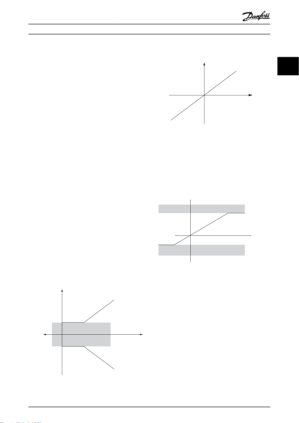
2.4.3 模拟和脉冲参照值和反馈值标定
参考值和反馈在模拟输入和脉冲输入中的标定方式相同。唯一的区别是,在指定最小和最大“端点值”(
P1 和 P2)之上或之下的参考值将被锁定在一起,而反馈则不然。
图 2.20 最小和最大端点值
图 2.20
中的
22 Danfoss A/S © 03/2019 全权所有。 MG06B541
Page 25

产品概述 设计指南
端点值 P1 和 P2 在
输入 模拟 53
P1 = (最小输入值, 最小参考值)
最小参考值
最小输入值
P2 = (最大输入值, 最大参考值)
最大参考值
最大输入值
表 2.3
中定义,具体取决于输入选择。
电压模式
参
数 6-14 Term
inal 53 Low
Ref./Feedb.
Value
参
数 6-10 Term
inal 53 Low
Voltage
参
数 6-15 Term
inal 53 High
Ref./Feedb.
Value
参
数 6-11 Term
inal 53 High
Voltage
[V]
[V]
模拟 53
电流模式
参
数 6-14 Termin
al 53 Low
Ref./Feedb.
Value
参
数 6-12 Termin
al 53 Low
Current
[mA]
参
数 6-15 Termin
al 53 High
Ref./Feedb.
Value
参
数 6-13 Termin
al 53 High
Current
[mA]
模拟 54
电压模式
参
数 6-24 Term
inal 54 Low
Ref./Feedb.
Value
参
数 6-20 Term
inal 54 Low
Voltage
[V]
参
数 6-25 Term
inal 54 High
Ref./Feedb.
Value
参
数 6-21 Term
inal 54 High
Voltage
[V]
模拟 54
电流模式
参
数 6-24 Termin
al 54 Low
Ref./Feedb.
Value
参
数 6-22 Termin
al 54 Low
Current
[mA]
参
数 6-25 Termin
al 54 High
Ref./Feedb.
Value
参
数 6-23 Termin
al 54 High
Current
[mA]
脉冲输入 29 脉冲输入 33
参
数 5-52 Term.
29 Low Ref./
Feedb. Value
参
数 5-50 Term.
29 Low
Frequency
[Hz]
参
数 5-53 Term.
29 High Ref./
Feedb. Value
参
数 5-51 Term.
29 High
Frequency
[Hz]
参数 5-57 Term.
33 Low Ref./
Feedb. Value
参数 5-55 Term.
33 Low Frequency
[Hz]
参数 5-58 Term.
33 High Ref./
Feedb. Value
参数 5-56 Term.
33 High Frequency
[Hz]
2 2
表 2.3 P1 和 P2 端点值
2.4.4 零周围的死区
有时,参考值(少数情况下反馈值也是如此)在零左右应该具有一个死区,确保机器在参考值“接近零”时停止。
要激活死区并设置死区大小,请执行下列操作:
设置 0 处的最小参考值(请参阅
•
图 2.21
确保定义标定图的两个点位于同一象限内。
•
的 X 轴上。
死区的大小由 P1 或 P2 定义,如
图 2.21
表 2.3
以获得相关参数)或最大参考值。换言之,P1 或 P2 必须位于
所示。
MG06B541 Danfoss A/S © 03/2019 全权所有。 23
Page 26
Resource output
[Hz] or “No unit”
Resource input
[mA]
Quadrant 2
Quadrant 3
Quadrant 1
Quadrant 4
Terminal X high
Low reference/feedback
value
High reference/feedback
value
1
-50
165020
P1
P2
0
130BD446.10
forward
reverse
Terminal low
20
1
10
V
V
20
1
10
-20
130BD454.10
+
Analog input 53
Low reference 0 Hz
High reference 20 Hz
Low voltage 1 V
High voltage 10 V
Ext. source 1
Range:
0.0% (0 Hz)
100.0% (20 Hz)
100.0% (20 Hz)
Ext. reference
Range:
0.0% (0 Hz)
20 Hz 10V
Ext. Reference
Absolute
0 Hz 1 V
Reference
algorithm
Reference
100.0% (20 Hz)
0.0% (0 Hz)
Range:
Limited to:
0%- +100%
(0 Hz- +20 Hz)
Limited to: -200%- +200%
(-40 Hz- +40 Hz)
Reference is scaled
according to min
max reference giving a
speed.!!!
Scale to
speed
+20 Hz
-20 Hz
Range:
Speed
setpoint
Motor
control
Range:
-8 Hz
+8 Hz
Motor
Digital input 19
Low No reversing
High Reversing
Limits Speed Setpoint
according to min max speed.!!!
Motor PID
Hz
Hz
Dead band
Digital input
General Reference
parameters:
Reference Range: Min - Max
Minimum Reference: 0 Hz (0,0%)
Maximum Reference: 20 Hz (100,0%)
General Motor
parameters:
Motor speed direction:Both directions
Motor speed Low limit: 0 Hz
Motor speed high limit: 8 Hz
产品概述
VLT® AutomationDrive FC 360
22
图 2.21 死区大小
用例 1: 带死区的正参考值,数字输入激活反向,第 I 部分
图 2.22
示出了极限在下限到上限范围之内的参考值输入是如何锁定的。
图 2.22 锁定极限在下限到上限范围之内的参考值输入
24 Danfoss A/S © 03/2019 全权所有。 MG06B541
Page 27
+
30 Hz
1
10
20 Hz
1
10
130BD433.11
-20 Hz
V
V
Analog input 53
Low reference 0 Hz
High reference 20 Hz
Low voltage 1 V
High voltage 10 V
Ext. source 1
Range:
0.0% (0 Hz)
150.0% (30 Hz)
150.0% (30 Hz)
Ext. reference
Range:
0.0% (0 Hz)
30 Hz 10 V
Ext. Reference
Absolute
0 Hz 1 V
Reference
algorithm
Reference
100.0% (20 Hz)
0.0% (0 Hz)
Range:
Limited to:
-100%- +100%
(-20 Hz- +20 Hz)
Limited to: -200%- +200%
(-40 Hz- +40 Hz)
Reference is scaled
according to
max reference giving a
speed.!!!
Scale to
speed
+20 Hz
-20 Hz
Range:
Speed
setpoint
Motor
control
Range:
–10 Hz
+10 Hz
Motor
Digital input 19
Low No reversing
High Reversing
Limits Speed Setpoint
according to min max speed.!!!
Motor PID
Dead band
Digital input
General Reference
parameters:
Reference Range: -Max - Max
Minimum Reference: Don't care
Maximum Reference: 20 Hz (100.0%)
General Motor
parameters:
Motor speed direction: Both directions
Motor speed Low limit: 0 Hz
Motor speed high limit: 10 Hz
产品概述 设计指南
用例 2: 带死区的正参考值,数字输入激活反向,第 II 部分
图 2.23
例示了极限在负最大至正最大范围之外的参考值输入如何在与外部参考值叠加之前锁定到输入上限和下限之间,
以及如何使用参考值算法将外部参考值锁定到负最大至正最大范围内。
2 2
图 2.23 锁定极限在负最大到正最大范围之外的参考值输入
MG06B541 Danfoss A/S © 03/2019 全权所有。 25
Page 28

产品概述
VLT® AutomationDrive FC 360
2.5 PID 控制
2.5.1 速度 PID 控制
22
参数 1-00 Configuration Mode
[0] 开环速度
[1] 闭环速度
[2] 转矩
[3] 过程
表 2.4 控制配置, 激活速度控制
1) “未激活”说明该特定模式可用,但该模式下,速度控制无效。
2) “不可用”说明该特定模式根本不存在。
参数 功能说明
参数 7-00 Speed PID Feedback Source
参数 7-02 速度 PID 比例增益
参数 7-03 Speed PID Integral Time
参数 7-04 Speed PID Differentiation
Time
参数 7-05 Speed PID Diff. Gain Limit
参数 7-06 Speed PID Lowpass Filter
Time
参数 1-01 Motor Control Principle
U/f
1)
未激活
2)
不可用
未提供 未激活
未激活 未激活
选择速度 PID 从哪个输入获得反馈。
该值越高,控制越快。但值太高可能会导致振荡。
排除稳态速度错误。值越低,说明反应速度越快。但值太低可能会导致振荡。
提供与反馈变化率成比例的增益。设置为零将禁用微分器。
如果给定应用中的参考值或反馈发生快速变化(这表示偏差变化迅速),则微分器将很快
起主要作用。因为微分器能对偏差变化做出反应。偏差变化越快,微分器增益就越强。这
样可以限制微分器增益,以便设置适于慢速变化的合理微分时间和适于快速变化的适当快
速增益。
低通滤波器可消除反馈信号的振荡,从而提高稳态性能。但是滤波时间过长会降低速度
PID 控制的动态性能。
参数 7-06 速度 PID 低通滤波
编码器 PPR
512 10 ms
1024 5 ms
2048 2 ms
4096 1 ms
的实际设置应采用来源编码器上的每转脉冲数 (PPR):
+
VVC
未激活
已激活
参数 7-06 Speed PID Lowpass Filter
Time
表 2.5 速度控制参数
设置速度控制的示例
在此例中,速度 PID 控制用于维护恒定的电机速度,而无论电机负载如何变化。所需电机速度通过与端子 53 相连的电
位计设置。速度范围是 0-1500 RPM(对应电位计上的 0-10V)。连接到端子 18 的开关用于控制启动和停止。速度 PID
通过使用 24 V (HTL) 增量编码器作为反馈来监视电机的实际 RPM。反馈传感器是连接到端子 32 和端子 33 的编码器
(1024 脉冲每转)。端子 32 和 33 的脉冲频率范围为 4 Hz–32 kHz。
26 Danfoss A/S © 03/2019 全权所有。 MG06B541
Page 29
M
3
96 97 9998
91 92 93 95
50
12
L1 L2L1PEL3
W PEVU
F1
L2
L3
N
PE
18
53
27
55
32
33
24 Vdc
130BD372.11
产品概述 设计指南
2 2
图 2.24 速度控制编程
按照
表 2.6
中的步骤设置速度控制(请参阅
在
表 2.6
中,假设所有其他参数和开关都保持默认设置。
功能 参数编号 设置
1) 确保电动机正常运行。请执行下列操作:
使用铭牌数据来设置电动机参数。
执行 AMA。
编程指南
中的设置说明)
参数组 1-2* 电动机数据
参数 1-29 自动电动机调
整 (AMA)
2) 检查电机是否正在运行,编码器连接是否正常。请执行下列操作:
按 [Hand On](手动启动)。检查电机是否正在运行,并
记下转动方向(以下称作“正向”)。
3) 确保变频器极限值已设置为安全值:
为参考值设置可以接受的极限值。
设置一个正参考值。
参数 3-02 最小参考值
参数 3-03 最大参考值
检查加减速设置是否在变频器功能和允许的应用操作规范
范围内。
参数 3-41 斜坡 1 加速时
间
参数 3-42 斜坡 1 减速时
为电机速度和频率设置可以接受的极限值。
间
参数 4-12 电动机速度下
限 [Hz]
参数 4-14 电动机速度上
限 [Hz]
4) 配置速度控制,并选择电机控制原理:
激活速度控制
选择电机控制原理
5) 配置并标定速度控制的参考值:
将模拟输入 53 设置为参考值源。
参数 4-19 最大输出频率
参数 1-00 配置模式 [1] 闭环速度
参数 1-01 电动控制原理
参数 3-15 参考值来源
1
在电机铭牌上标识。
[1] 启用完整 AMA
0
50
默认设置
默认设置
0 Hz
50 Hz
60 Hz
+
[1] VVC
非必需设置(默认)
MG06B541 Danfoss A/S © 03/2019 全权所有。 27
Page 30

P 7-30
normal/inverse
PID
P 7-38
*(-1)
Feed forward
Reference
Handling
Feedback
Handling
% [unit]
% [unit]
%
[unit]
%
[speed]
Scale to
speed
P 4-10
Motor speed
direction
To motor
control
Process PID
130BA178.10
_
+
0%
-100%
100%
0%
-100%
100%
产品概述
VLT® AutomationDrive FC 360
标定模拟输入 53 0 Hz (0 V) 至 50 Hz (10 V)
参数组 6-1* 模拟输入
非必需设置(默认)
1
6) 将 24 V HTL 编码器信号配置为电机控制和速度控制的反馈:
22
将数字输入 32 和 33 设置为编码器输入。
参数 5-14 端子 32 数
[82] 编码器输入 B
字输入
参数 5-15 端子 33 数
[83] 编码器输入 A
字输入
选择端子 32/33 作为速度 PID 反馈。
7) 调整速度控制 PID 参数:
在适当时候遵循调整原则或手动调整。
参数 7-00 速度 PID 反馈源[1] 24 V 编码器
参数组 7-0* 速度 PID
控制
8) 完成:
将参数设置保存到 LCP 中进行安全保管。
表 2.6 速度 PID 控制的编程顺序
参数 0-50 LCP Copy [1] 所有参数到 LCP
2.5.2 过程 PID 控制
过程 PID 控制可用于控制那些可以用传感器测量的应用参数(例如压力、温度和流量),以及那些会受到所连接的电机
影响(通过泵、风扇或其他所连设备施加影响)的参数。
表 2.7
列出了可以进行过程控制的控制配置。请参考
章 2.3 控制结构
查看“速度控制”的适用情况。
参数 1-00 配置模式 参数 1-01 电动控制原理
U/f
[3] 过程
表 2.7 控制配置
未提供 过程
注意
过程控制 PID 将在默认参数设置下工作,但建议调整参数以优化应用控制性能。
图 2.25 过程 PID 控制图
VVC
+
28 Danfoss A/S © 03/2019 全权所有。 MG06B541
Page 31
产品概述 设计指南
2.5.3 过程控制相关参数
参数 功能说明
参数 7-20 反馈 1 来源
参数 7-22 过程 CL 反馈 2 的源
参数 7-30 PID 正常/反向控制
参数 7-31 过程 PID 防积分饱和
参数 7-32 过程 PID 控制启动速度值
参数 7-33 过程 PID 比例增益
参数 7-34 过程 PID 积分时间
参数 7-35 过程 PID 微分时间
参数 7-36 过程 PID 微分增益极限
参数 7-38 过程 PID 前馈因数
参数 6-16 53 端滤波器时间
•
53)
参数 6-26 54 端滤波器时间
•
54)
(模拟端子
(模拟端子
选择过程 PID 应该从哪个源(模拟或脉冲输入)获得反馈。
可选: 确定过程 PID 是否(以及从哪里)获得其他反馈信号。如果选择了其他反馈
源,则将叠加这两个反馈信号,然后再在过程 PID 控制中使用。
在
[0] 正常运行
作
中,过程控制将降低电机速度。
防积分饱和功能可保证当达到频率极限或转矩极限时,积分器将设置为对应于实际频率的
增益。这样可避免在出现无法通过速度更改来补偿的故障时进行积分。按
禁用此功能。
在某些应用中,要达到所需速度/设置点可能需要非常长时间。在此类应用中,在激活过
程控制之前先通过变频器设置一个固定的电机速度可能比较有利。通过在
PID 控制启动速度值
该值越高,控制越快。但值太高可能会导致振荡。
排除稳态速度错误。值越低,则表示反应速度越快。但值太低可能会导致振荡。
提供与反馈变化率成比例的增益。设置为零将禁用微分器。
如果给定应用中的参考值或反馈发生快速变化(这表示偏差变化迅速),则微分器将很快
起主要作用。因为微分器能对偏差变化做出反应。偏差变化越快,微分器增益就越强。这
样可以限制微分增益以允许为缓慢变化设置合理的微分时间。
在过程参考值和获得该参考值所需的电机速度之间有良好相关性(并接近于线性)的应用
中,可以使用前馈因数来获得更好的过程 PID 控制动态性能。
如果电流/电压反馈信号出现振荡,则可以使用低通滤波器来使其衰减。
示例: 如果低通滤波器设置为 0.1 秒,则极限速度将为 10 RAD/秒(0.1 秒 的倒
数),相当于 (10/(2 x π))= 1.6 Hz。这意味着滤波器将减弱那些变化频率超过每秒
1.6 次振荡的所有电流/电压。只有对频率(速度)变化小于 1.6 Hz 的反馈信号才执行
该控制。
低通滤波器可以提高稳态性能,但选择过长的滤波时间会降低过程 PID 控制的动态性
能。
下,如果反馈低于参考值,过程控制将增加电机速度。在
[0] 关闭
参数 7-32 过程
中设置过程 PID 启动值(速度)来设置固定电机速度。
2 2
[1] 反向操
可
表 2.8 过程控制参数
2.5.4 过程 PID 控制示例
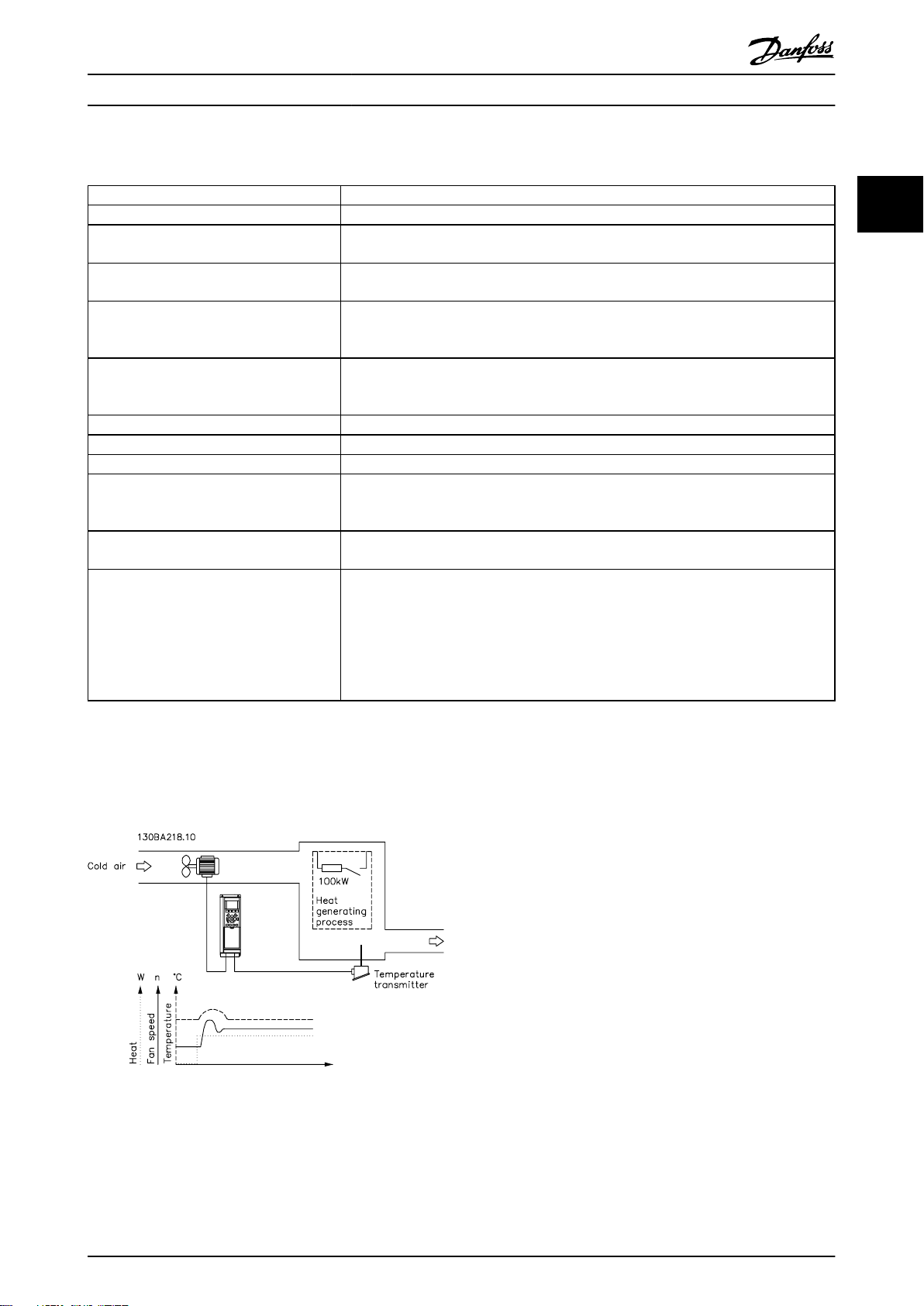
图 2.26
在通风系统中,可以使用 0-10 V 的电位计将温度设置在
-5 至 +35 °C (23–95 °F) 之间。要使所设置的温度保
持恒定,可使用过程控制。
是通风系统中使用的过程 PID 控制示例:
图 2.26 通风系统中的过程 PID 控制
这种控制类型是反向的,即,当温度升高时,通风速度随
之提高,同时产生更多的空气。当温度降低时,速度随之
减小。所使用的传感器是温度传感器,其工作范围为 -10
至 +40 °C (14–104 °F),4–20 mA。
MG06B541 Danfoss A/S © 03/2019 全权所有。 29
Page 32

Transmitter
96 97 9998
91 92 93 95
50
12
L1 L2L1PEL3
W PEVU
F1
L2
L3
N
PE
130BD373.10
18
53
27
55
54
M
3
产品概述
VLT® AutomationDrive FC 360
1. 通过与端子 18 相连的开关来控制启动/停止。
2. 通过与端子 53 相连的电位计(-5 至 +35 °C
22
(23–95 °F) , 0–10 V DC ) 来测量温度参考
值。
3. 通过与端子 54 相连的传感器(-10 至 +40 °C
(14–104 °F),4–20 mA)来获得温度反馈。
图 2.27 2 线传感器
功能 参数编号 设置
将变频器初始化。
参
[2] 初始化
- 执行一次电源循环 - 按复位键。
数 14-22 工
作模式
1) 设置电机参数:
根据铭牌数据设置电机参数。
参数组 1-2*
按照电机铭牌上的指示。
电动机数据
执行完整 AMA。
参数 1-29 电
[1] 启用完整 AMA
。
机自动整定
(AMA)
2) 检查电机是否按正确方向运行。
如果简单地按照 U 对 U、 V 对 V、 W 对 W 的相序将电机连接至变频器,电机主轴通常会顺时钟转动(向轴端方向看)。
按 [Hand On](手动启动)。通过施加一个手动
参考值,检查电机轴的转动方向。
如果电机的旋转方向与所要求的相反:
1. 在
参数 4-10 电动机速度方向
向。
2. 切断主电源并等待直流回路放电。
3. 切换电机相的 2 相。
设置配置模式。
中更改电机方
参数 4-10 电
机速度方向
参数 1-00 配
选择正确的电机轴转向。
[3] 过程
。
置模式
3) 设置参考值配置,即,参考值处理范围。在
参数组 6-** 模拟输入/输出
中设置模拟输入标定:
30 Danfoss A/S © 03/2019 全权所有。 MG06B541
Page 33

产品概述 设计指南
功能 参数编号 设置
设置参考值/反馈值的单位。
设置最小参考值 (10 °C (50 °F))。
设置最大参考值 (80 °C (176 °F))。
如果设定值由预置值(数组参数)确定,则将其它
参考值来源设为
[0] 无功能
。
参数 3-01
Reference/
Feedback
Unit
参数 3-02
Minimum
Reference
参数 3-03
[60] °C
-5 °C (23 °F)。
35 °C (95 °F).
[0] 35%
参考值
参数 3-14 Preset Relative Reference
Scaling Reference Resource [0] = 无功能
Maximum
Reference
参数 3-10
Preset
Reference
4) 调整变频器的极限:
将加减速时间设成一个合适的值,如 20 秒。
参数 3-41
Ramp 1 Ramp
20 s
20 s
Up Time
参数 3-42
Ramp 1 Ramp
Down Time
设置速度下限。
设置电机速度上限。
设置最大输出频率。
参数 4-12
Motor Speed
Low Limit
10 Hz
50 Hz
60 Hz
[Hz]
参数 4-14
Motor Speed
High Limit
[Hz]
参数 4-19
Max Output
Frequency
将
参数 6-19 Terminal 53 mode 和参数 6-29 Terminal 54 mode
5) 标定用于参考值和反馈的模拟输入:
设置“端子 53 低电压”。
设置“端子 53 高电压”。
设置“端子 54 低反馈值”。
设置“端子 54 高反馈值”。
设置反馈来源。
参数 6-10
Terminal 53
Low Voltage
参数 6-11
Terminal 53
设置为电压或电流模式。
0 V
10 V
-5 °C (23 °F)
35 °C (95 °F)
[2] 模拟输入 54
High Voltage
参数 6-24
Terminal 54
Low Ref./
Feedb. Value
参数 6-25
Terminal 54
High Ref./
Feedb. Value
参数 7-20
Process CL
Feedback 1
Resource
6) 基本 PID 设置:
,此单位将在显示器上示出。
。
Par . 3 − 10
=
0
× Par .3 − 03 − par . 3 − 02 = 24, 5°C
100
至
参数 3-18 Relative
。
2 2
MG06B541 Danfoss A/S © 03/2019 全权所有。 31
Page 34

130BA183.10
y(t)
t
P
u
产品概述
功能 参数编号 设置
过程 PID 正常/反向。
22
过程 PID 防积分饱和。
过程 PID 启动速度。
将参数保存到 LCP 中。
表 2.9 过程 PID 控制设置示例
VLT® AutomationDrive FC 360
参数 7-30
Process PID
Normal/
Inverse
Control
参数 7-31
Process PID
Anti Windup
参数 7-32 过
程 PID 启动
速度
参
数 0-50 LCP
复制
[0] 正常
[1] 开
300 RPM
[1] 所有参数到 LCP
2.5.5 过程控制器优化
按
章 2.5.5 编程顺序
益、积分时间和微分时间(
所述配置基本设置后,优化比例增
参数 7-33 过程 PID 比例增
益、参数 7-34 过程 PID 积分时间 和参数 7-35 过程
PID 微分时间
)。在大多数过程中,完成以下操作步骤:
1. 启动电动机。
2. 将
参数 7-33 过程 PID 比例增益
设为 0.3,
并增大该值直到反馈信号再次开始失稳为止。然
后减小该值,直到反馈信号稳定为止。将比例增
益降低 40 - 60%。
3. 将
参数 7-34 过程 PID 积分时间
设为 20
秒,并减小该值直到反馈信号再次开始失稳为
止。然后延长积分时间,直到反馈信号稳定为
止,最后将该值再增大 15-50%。
4. 只能将
参数 7-35 过程 PID 微分时间
用于快
速反应系统(微分时间)。一般取值是所设定积
分时间的四倍。当比例增益和积分时间的设置完
全优化后使用微分器。确保低通滤波器可以充分
减弱反馈信号的振荡。
注意
如有必要,可多次启用“启动/停止”,以产生不稳定的反
馈信号。
对反馈的测量),即,直到系统处于临界稳定状态为止。
对应的增益
振荡周期
(Ku)
称作基本增益,是出现振荡时的增益。
(Pu)
(称作基本周期)按
图 2.28
中所示的方
式确定,应在振荡幅度很小时进行测量。
1. 只选择比例控制,即将积分时间设置为最大值,
而将微分时间设置为 0。
2. 增大比例增益的值,直至达到不稳点(持续振
荡)和临界增益值
3. 测量振荡期以获得临界时间常量
4. 利用
表 2.10
K
。
u
P
。
u
计算所需的 PID 控制参数。
过程操作员可以对控制器执行最终迭代调整以获得满意的
控制效果。
2.5.6 Ziegler Nichols 调整方法
要调整变频器的 PID 控制,Danfoss 推荐使用 Ziegler
Nichols 调整方法。
注意
对于会受到因临界稳定控制设置而引起的振荡损坏的应用
场合,切勿使用 Ziegler Nichols 调整方法。
应根据对处于稳定性极限的系统的判断而不是逐步响应对
参数进行调整。增大比例增益直至观察到持续振荡(通过
32 Danfoss A/S © 03/2019 全权所有。 MG06B541
图 2.28 临界稳定系统
控制类型 比例增益 积分时间 微分时间
PI 控制 0.45 x
PID 严格控制 0.6 x
PID 略微过冲 0.33 x
表 2.10 对调节器进行 Ziegler Nichols 调整
K
0.833 x
u
K
0.5 x
u
K
0.5 x
u
P
u
P
u
P
u
–
0.125 x
0.33 x
P
u
P
u
Page 35

1
2
z
z
z
L1
L2
L3
PE
U
V
W
C
S
I
2
I
1
I
3
I
4
C
S
C
S
C
S
C
S
I
4
C
S
z
PE
3
4
5
6
175ZA062.12
产品概述 设计指南
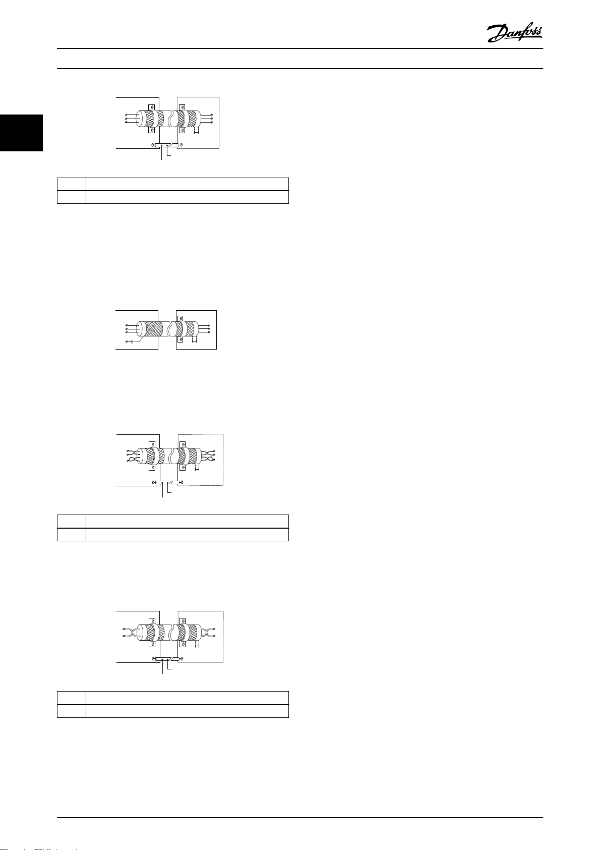
2.6 EMC 辐射和抗扰性
2.6.1 关于 EMC 辐射的一般问题
系统通常会传导 150 kHz 到 30 MHz 频率范围内的电气干扰。在变频器系统中,变频器、电机电缆和电机会产生 30
MHz 到 1 GHz 范围的空中干扰。
电动机电缆中的电容性电流与电动机的高 dU/dt 特性一起产生了泄漏电流。
使用屏蔽电机电缆会增大泄漏电流(请参阅
漏电流进行滤波,它将在主电源上对 5 MHz 左右以下的无线电频率范围产生更大的干扰。由于泄漏电流 (I1) 会通过屏
蔽层电流 (I3) 返回设备,屏蔽的电机电缆仅产生一个微弱的电磁场 (I4)。
屏蔽层降低了辐射性干扰,但增强了主电源的低频干扰。将电机电缆的屏蔽层同时连接到变频器机箱和电机机箱。此时最
好使用整体性的屏蔽层夹,以避免屏蔽层端部纽结(辫子状)。屏蔽层夹会增加屏蔽层在高频下的阻抗,从而降低屏蔽效
果并增大泄漏电流 (I4)。
如果将屏蔽电缆用于以下目的,则在机箱两端安装屏蔽层:
现场总线
•
网络
•
继电器
•
控制电缆
•
信号接口
•
制动
•
图 2.29
),因为与非屏蔽电缆相比,屏蔽电缆的对地电容更高。如果不对泄
2 2
但有时为了避免电流回路,也可能需要断开屏蔽层。
1 接地电缆
2 屏蔽
3 交流主电源
4 变频器
5 屏蔽电机电缆
6 电机
图 2.29 EMC 辐射
如果要将屏蔽层置于变频器的固定板上,则使用金属固定板将屏蔽层电流带回设备。还应确保从固定板到固定螺钉以及变
频器机架都有良好的电气接触。
MG06B541 Danfoss A/S © 03/2019 全权所有。 33
Page 36

产品概述
VLT® AutomationDrive FC 360
在使用无屏蔽电缆时,尽管可能符合抗扰性要求,但却不符合某些辐射要求。
为了尽量降低整个系统(设备 + 安装)的干扰水平,请使用尽可能短的电机电缆和制动电缆。不要将传送敏感信号电平
22
的电缆与主电源电缆、电机电缆和制动电缆放在一起。控制性电子元件尤其可能产生 50 MHz 以上的无线电干扰(空中干
扰)。
2.6.2 EMC 辐射要求
表 2.11
A1
滤波器
A2
滤波器
中的测试结果是使用由变频器(带固定板)、电机和屏蔽电机电缆组成的系统获得的。
A 类组 2/EN 55011
工业环境
机箱规格和额定功率
0.37–2.2 kW (0.5–3.0 hp), 380–480
J1
3.0–5.5 kW (4.0–7.5 hp), 380–480
J2
J3 7.5 kW (10 hp), 380–480 V – – 25 m (82 ft) 是
J4 11–15 kW (15–20 hp), 380–480 V – – 25 m (82 ft) 是
J5 18.5–22 kW (25–30 hp), 380–480 V – – 25 m (82 ft) 是
0.37–2.2 kW (0.5–3.0 hp), 380–480
J1
3.0–5.5 kW (4.0–7.5 hp), 380–480
J2
J3 7.5 kW (10 hp), 380–480 V 5 m (16.4 ft)
J4 11–15 kW (15–20 hp), 380–480 V 5 m (16.4 ft)
J5 18.5–22 kW (25–30 hp), 380–480 V 5 m (16.4 ft)
J6 30–45 kW (40–60 hp), 380–480 V 25 m (82 ft)
J7 55–75 kW (75–100 hp), 380–480 V 25 m (82 ft)
V
V
V
V
C3 类/EN/IEC 61800-3
二类环境
传导性干扰 辐射性干扰 传导性干扰 辐射性干扰
– – 25 m (82 ft) 是
– – 25 m (82 ft) 是
5 m (16.4 ft)
5 m (16.4 ft)
1)
是
1)
是
1)
是
1)
是
1)
是
1)
是
1)
是
A 类组 1/EN 55011
工业环境
C2 类/EN/IEC 61800-3
受限一类环境
– –
– –
– –
– –
– –
– –
– –
表 2.11 EMC 辐射(滤波器类型: 内部)
1) 150 kHz 至 30 MHz 的频率范围在 IEC/EN 61800-3 和 EN 55011 之间未统一,不是必须包括。
2.6.3 EMC 抗扰性要求
变频器的抗扰性要求取决于它们的安装环境。工业环境的要求要高于家庭和办公室环境的要求。Danfoss 所有变频器均符
合工业环境的要求。因此,这些变频器还符合较低的、具有较大安全宽限的家庭和办公室环境要求。
要记录因电气现象而导致的瞬态脉冲的抗扰性,可在由以下部件组成的系统中执行下列抗扰性测试:
一个变频器(带有相关选件)。
•
屏蔽控制电缆。
•
带有电位计、电机电缆和电机的控制盒。
•
所有测试均按照以下基本标准执行:
EN 61000-4-2 (IEC 61000-4-2) 静电放电 (ESD): 模拟人体的静电放电。
•
EN 61000-4-3 (IEC 61000-4-3) 辐射抗扰度: 通过幅度调制来模拟雷达和无线电通信设备和移动通信设备的
•
效应。
EN 61000-4-4 (IEC 61000-4-4) 瞬态脉冲: 模拟接触器、继电器或类似设备在开关时的干扰效应。
•
34 Danfoss A/S © 03/2019 全权所有。 MG06B541
Page 37

产品概述 设计指南
EN 61000-4-5 (IEC 61000-4-5) 瞬态浪涌: 模拟安装环境附近的闪电等现象导致的瞬态浪涌。
•
EN 61000-4-6 (IEC 61000-4-6) 传导抗扰度: 模拟与连接电缆相连的无线传输设备的效应。
•
抗扰度要求应遵循产品标准 IEC 61800-3。有关详细信息,请参阅
电压范围: 380–480 V
产品标准 61800-3
测试 ESD 辐射抗扰度 瞬态 电涌 传导抗扰度
认可标准 B B B A A
主电源电缆 – – 2 kV CN
电机电缆
制动电缆 – –
负载共享电缆 – –
继电器电缆
控制电缆 – –
标准/现场总线电缆 – –
LCP 电缆 – –
机箱
– – 4 kV CCC –
– – 4 kV CCC –
4 kV CD
8 kV AD
10 V/m – – –
表 2.12
4 kV CCC –
4 kV CCC –
长度 >2 m
(6.6 ft)
1 kV CCC
长度 >2 m
(6.6 ft)
1 kV CCC
长度 >2 m
(6.6 ft)
1 kV CCC
。
2 kV/2 Ω DM
2 kV/12 Ω CM
非屏蔽电缆:
1 kV/42 Ω CM
非屏蔽电缆:
1 kV/42 Ω CM
10 V
RMS
10 V
RMS
10 V
RMS
10 V
RMS
10 V
RMS
10 V
RMS
10 V
RMS
–
10 V
RMS
2 2
表 2.12 EMC 抗扰性要求
定义:
CD: 接触放电
AD: 空气放电
DM: 差分模式
CM: 共模
CN: 通过耦合网络直接注入
CCC: 通过电容耦合夹持注入
高低压绝缘
2.7
PELV 通过极低电压提供保护 。如果电源为 PELV 类型,
且安装符合地方/国家对 PELV 电源的规定,则可避免发
生触电。
所有控制端子和继电器端子 01-03/04-06 都符合 PELV
(保护性超低压)标准。这种不适用于 400 V 以上的接
地三角形支路。
如果能满足较高绝缘要求并保证相应空间间隔,则可以获
得令人满意的电隔离效果。EN 61800-5-1 标准对这些要
求进行了专门介绍。
构成电气绝缘装置的部件(如
图 2.30
所示)还必须满足
较高的绝缘标准并通过 EN 61800-5-1 规定的相关测试。
PELV 电隔离可在 3 个位置出现(如
图 2.30
所示):
为了保持 PELV,所有与控制端子的连接都必须是 PELV
的,比如,必须对热敏电阻实行双重绝缘,以加强其绝缘
性能。
MG06B541 Danfoss A/S © 03/2019 全权所有。 35
Page 38

130BD447.11
12
4
3
ab
M
130BB955.12
a
b
Leakage current
Motor cable length
130BB956.12
THDv=0%
THDv=5%
Leakage current
产品概述
VLT® AutomationDrive FC 360
漏电电流还取决于线路失真情况。
22
1 用于控制盒的电源 (SMPS)
2 功率卡与控制盒之间的通信
3 客户继电器
图 2.30 电隔离
标准 RS485 与 I/O 电路 (PELV) 之间的接口是功能隔
离的。
警告
接触任何电气部件前,还需确保所有其他电压输入都已断
开,例如负载共享(直流中间电路的连接),以及用于借
能运行的电机连接。至少等待在
如果不遵守建议,将可能导致死亡或严重伤害。
2.8 接地漏电电流
遵守对漏电电流超过 3.5 mA 的设备进行保护性接地的国
家和地方法规。
变频器技术在高功率下利用高频切换。这会在接地线路中
产生漏电电流。变频器输出功率端子中的故障电流可能包
含直流成分,这些直流成分可能对滤波电容器充电,从而
导致瞬态地电流。
接地漏电电流由多种成分构成,取决于不同的系统配置,
包括射频干扰滤波、屏蔽型电机电缆和变频器功率。
表 1.2
中指定的时间。
图 2.32 线路失真对漏电电流的影响。
注意
泄漏电流高可能会导致 RCD 关闭。为避免此问题,在为
滤波器充电时,拆除 RFI 螺钉(机箱规格 J1 至 J5)
或将
参数 14-50 射频干扰滤波器
箱规格 J6 和 J7)。
EN/IEC61800-5-1(功率变频器系统产品标准)要求,如果
漏电电流超过 3.5mA,则须给予特别注意。必须采用下述
方式之一来增强接地措施:
截面积至少为 10 mm2 的地线(端子 95)。
•
采用两条单独的并且均符合尺寸规格的接地线。
•
有关详细信息,请参阅 EN/IEC61800-5-1。
使用 RCD
在使用漏电断路器 (RCD)(也称为接地漏电断路器,简称
ELCB)时,应符合下述要求:
仅使用可以检测交流和直流的 B 类 RCD。
•
使用带有涌入延迟功能的 RCD,以防瞬态地电流
•
造成故障。
根据系统配置和环境因素来选择 RCD 规格。
•
设置为
[0] 关
(机
图 2.31 电缆长度和功率规格对漏电电流的影响,Pa>P
36 Danfoss A/S © 03/2019 全权所有。 MG06B541
b
Page 39
130BB958.12
f
sw
Cable
150 Hz
3rd harmonics
50 Hz
Mains
RCD with low f
cut-
RCD with high f
cut-
Leakage current
Frequency
130BB957.11
Leakage current [mA]
100 Hz
2 kHz
100 kHz
产品概述 设计指南
图 2.33 漏电电流的主要成分
2.9
制动功能
2.9.1 机械夹持制动
直接安装在电动机上的机械夹持制动通常执行静态制动。
注意
当安全链中包括夹持制动时,变频器不能提供机械制动的
安全控制。在总安装中包括用于制动控制的冗余电路。
2.9.2 动态制动
动态制动由下列内容建立:
电阻器制动: 制动 IGBT 会将过电压保持在某
•
个特定阈值之下,其方式是将制动能量从电机定
向到连接的制动电阻器(
[1] 电阻器制动
使用 70 V 范围在
整阈值。
交流制动: 制动能量在电机中通过更改电机中
•
的损耗情况进行分配。交流制动功能不能在循环
频率较高的应用中使用,因为这样可能会使电机
参数 2-10 制动功能
过热(
动
)。
直流制动: 添加到交流电流中的过调制直流电
•
流用作旋转电流制动(
≠0 s)。
)。
参数 2-10 制动功能
参数 2-14 制动电压衰减
=
[2] 交流制
参数 2-02 直流制动时间
调
2 2
=
图 2.34 RCD 的截止频率对做出的响应/执行的测量的影响
有关详细信息,请参考
RCD 应用说明
。
2.9.3 制动电阻器选择
为满足发电式制动操作的更高要求,必须使用一个制动电
阻器。通过使用制动电阻器,可以确保所产生的热将被制
动电阻器(而不是变频器)所吸收。有关详细信息,请参
VLT® Brake Resistor MCE 101 设计指南
阅《
如果在每次制动期间传输到该电阻器的动能量是未知的,
则可以根据周期和制动时间来计算平均功率。电阻器间歇
工作周期即为电阻器的工作周期。
个典型的制动周期。
该电阻的间歇工作周期按下述方式计算:
工作周期 = tb/T
tb 是制动时间(秒)
T = 周期时间(秒)。
。
图 2.35
》。
下图显示了一
MG06B541 Danfoss A/S © 03/2019 全权所有。 37
Page 40

T
ta
tc
tb
to ta
tc
tb
to ta
130BA167.10
Charge
Temps
Vitesse
产品概述
VLT® AutomationDrive FC 360
Danfoss 建议按照下面公式计算制动电阻 R
。建议使用
rec
的制动电阻值可确保变频器在 160% 的最高制动转矩
(M
) 时实现制动。
br(%)
22
2
U
x100x0.83
P电机xM
dc
br( % )
xη
VLT
xη
电机
通常为 0.80 (≤ 75 kW/100 hp); 0.85 (11–
可表示为:
rec
396349
=
rec
397903
=
rec
1)
Ω
P
电机
2)
Ω
P
电机
。
min
图 2.35 典型的制动周期
功率范围
0.37–75 kW (0.5–
1)
100 hp)
380–480 V
周期时间(秒) 120
100% 转矩时的制动工作周期 持续
过载转矩 (150/160%) 时的制动工作周
期
40%
表 2.13 高过载转矩时的制动
1) 对于 30–75 kW (40–100 hp) 变频器,外部制动电阻器必
须符合表 2.13 中的规格。
Danfoss 提供了工作周期为 10% 和 40% 的制动电阻
器。如果使用工作周期为 10% 的制动电阻器,则它可以
在一个周期的 10% 的时间内吸收制动功率。其余 90% 的
周期时间将用于耗散过多的热量。
注意
确保电阻器在设计上可以承受所要求的制动时间。
R
Ω =
rec
η
motor
22 kW/15–30 hp).
η
通常为 0.97。
VLT
对于 FC 360,160% 制动转矩下的 R
480V :R
480V :R
1) 对于主轴输出 ≤ 7.5 kW (10 hp) 的变频器
2) 对于主轴输出为 11–75 kW (15–100 hp) 的变频器
注意
制动电阻器的阻值不得高于 Danfoss 推荐的值。如果选择
了具有更高阻值的制动电阻器,可能无法达到 160% 的制
动转矩,因为变频器可能出于安全原因而自动关闭。
阻值应大于 R
注意
如果制动电阻器发生短路,则必须使用电网开关或接触器
断开变频器的主电源才能避免制动电阻器上的功率消耗。
(接触器可由变频器控制)。
注意
制动电阻器在制动期间可能会变得很烫,因此请不要触摸
它。为避免火灾风险,请在安全环境中安放制动电阻器。
制动电阻器的最大允许负载由给定间歇工作周期的峰值功
2.9.4 通过制动功能进行控制
率表示,可以按下述方式计算:
制动功能可防止制动电阻器发生短路。为此,制动晶体管
制动电阻计算
2
U
x0 . 83
dc,br
Ω =
R
br
P
peak
其中,
P
= P
peak
motor
x Mbr [%] x η
motor
x η
VLT
[W]
将受到监测,以确保能检测到晶体管的短路。可以使用继
电器/数字输出来防止制动电阻器因变频器中出现故障而发
生过载。
除此之外,制动系统还可读取最近 120 秒的瞬时功率和
平均功率。制动系统还可以监测功率激励,以确保它不会
超过在
参数 2-12 制动功率极限 (kW)
中选择的极限。
如公式中所示,制动电阻器取决于直流回路电压 (Udc)。
规格 正常制动
U
dc,br
FC 360
3x380–480 V
使用 70 V 范围在
770 V 800 V 800 V
参数 2-14 制动电压衰减
值。
注意
切断警告 切断(跳闸)
内调整阈
注意
制动功率监视并不是一项安全功能。需要使用温度开关来
防止制动功率超出限值。制动电阻器电路没有接地泄漏保
护。
可以在
(专用制动电阻器)作为替代的制动功能。此功能对所有
设备均适用。使用此功能可确保避免直流回路电压升高时
跳闸。这是通过提高输出频率以限制直流回路电压来实现
的。因为可以避免变频器跳闸,所以这是一种非常有用的
参数 2-17 过压控制
中选择
过压控制 (OVC)
确保制动电阻器可承受 410 V 或 820 V 的电压。
38 Danfoss A/S © 03/2019 全权所有。 MG06B541
Page 41

. . .
. . .
Par. 13-11
Comparator Operator
Par. 13-43
Logic Rule Operator 2
Par. 13-51
SL Controller Event
Par. 13-52
SL Controller Action
130BB671.13
Coast
Start timer
Set Do X low
Select set-up 2
. . .
Running
Warning
Torque limit
Digital input X 30/2
. . .
=
TRUE longer than..
. . .
. . .
130BA062.14
State 1
13-51.0
13-52.0
State 2
13-51.1
13-52.1
Start
event P13-01
State 3
13-51.2
13-52.2
State 4
13-51.3
13-52.3
Stop
event P13-02
Stop
event P13-02
Stop
event P13-02
Par. 13-11
Comparator Operator
=
TRUE longer than.
. . .
. . .
Par. 13-10
Comparator Operand
Par. 13-12
Comparator Value
130BB672.10
. . .
. . .
. . .
. . .
Par. 13-43
Logic Rule Operator 2
Par. 13-41
Logic Rule Operator 1
Par. 13-40
Logic Rule Boolean 1
Par. 13-42
Logic Rule Boolean 2
Par. 13-44
Logic Rule Boolean 3
130BB673.10
产品概述 设计指南
功能,例如,如果减速时间过短。在这种情况下,减速时
间延长了。
注意
在运行 PM 电机时无法激活 OVC(
构
设置为
[1] PM 非突出 SPM
2.10 智能逻辑控制器
智能逻辑控制 (SLC) 是一系列用户定义的操作(请参阅
参数 13-52 SL Controller Action
户定义事件(请参阅
[x])被 SLC 判断为“真” 时,将执行这些操作。
触发事件的条件可能是某个特定状态,也可能是在逻辑规
则或比较器操作数的输出为“真”时。这将导致相关操
作,如
图 2.36
参数 13-51 SL Controller Event
所示。
参数 1-10 电动机结
)。
[x]),当关联的用
2 2
图 2.37 包含 3 个事件/操作的序列
比较器
这些比较器可将连续的变量(如输出频率、输出电流和模
拟输入)与固定的预置值进行比较。
图 2.38 比较器
逻辑规则
使用逻辑运算符 AND、OR、NOT,将来自计时器、比较
器、数字输入、状态位和事件的布尔输入(“真”/“假”
输入)进行组合,最多组合三个输入。
图 2.36 相关操作
图 2.39 逻辑规则
事件和操作 都有自己的编号,两者关联在一起(状
态)。这意味着,当事件 [0] 符合条件(值为“真”)
时,将执行操作 [0]。此后会对事件 [1] 进行条件判
断,如果值为 TRUE,则执行操作 [1],依此类推。无论
何时,只能对一个事件进行判断。如果某个事件的条件判
断为“假”,在当前的扫描间隔中将不执行任何操作(在
SLC 中),并且不再对其他事件进行条件判断。当 SLC
在每个扫描间隔中启动后,它将首先判断事件 [0](并且
仅判断事件 [0])的真假。仅当对事件 [0] 的条件判断
为“真”时,SLC 才会执行操作 [0],并且开始判断事件
[1] 的真假。可以设置 1 到 20 个事件 和操作。
执行了最后一个事件/操作后,再次从事件 [0]/操作 [0]
开始执行该序列。
作:
MG06B541 Danfoss A/S © 03/2019 全权所有。 39
图 2.37
显示的示例带有三个事件/操
Page 42

产品概述
VLT® AutomationDrive FC 360
2.11 极端运行条件
短路(电机相间短路)
22
通过测量电动机三个相位中每一个相位的电流或者直流回
路的电流,可以实现对变频器的短路保护。2 个输出相位
之间产生短路可导致变频器过流。当短路电流超过允许的
值后,变频器将被单独关闭(
进行输出切换
在电机与变频器之间进行输出切换是完全允许的,不会损
坏变频器。但可能会显示故障信息。
电动机产生过电压
如果电动机用作发电机,则直流回路中的电压会升高。以
下情况下会出现此问题:
负载(以变频器的恒定输出频率)驱动电机。
•
减速时,如果惯性力矩较大,则摩擦较小,减速
•
时间会过短,从而导致变频器、电机和系统无法
消耗掉能量。
如果滑移补偿设置不当,可能导致直流回路的电
•
压升高。
如果可能,控制单元会试图更正减速过程 (
压控制
)。
当达到特定的电压水平时,变频器会关闭,以保护晶体管
和直流回路电容器。
要选择控制直流回路电压水平的方法,请参阅
数 2-10 制动功能
主电源断电
如果发生主电源断电,变频器将继续工作,直到直流回路
电压低于最低停止水平 (320 V)。断电前的主电源电压和
电机负载决定了逆变器惯性运动的时间。
VVC+ 模式下的静态过载
当变频器过载时(达到
和
数 4-17 发电时转矩极限
降低输出频率,以降低负载。
如果过载较为严重,则会产生电流,使变频器在大约 5
到 10 秒钟后自动关闭。
在转矩极限下的运行时间可以在
闸延迟
中限定(0-60 秒)。
报警 16,跳闸锁定
)。
参数 2-17 过
参
参数 2-17 过压控制
。
参数 4-16 电动时转矩极限/参
中的转矩极限),控制系统会
参数 14-25 转矩极限跳
速度下限
参数 4-12 电动机速度下限 [Hz]
的最小输出速度。
速度上限
用于设置变频器可提供
参数 4-14 电动机速度上限 [Hz] 或参数 4-19 最大输
出频率
用于设置变频器可提供的最大输出速度。
ETR(电子热敏继电器)
变频器 ETR 功能可测量实际电流、速度和时间来计算电
机温度。该功能还可保护电机,防止过热(警告或跳
闸)。此外还提供了外部热敏电阻输入。ETR 是一种根据
内部测量来模拟双金属继电器的电子功能。其特性如
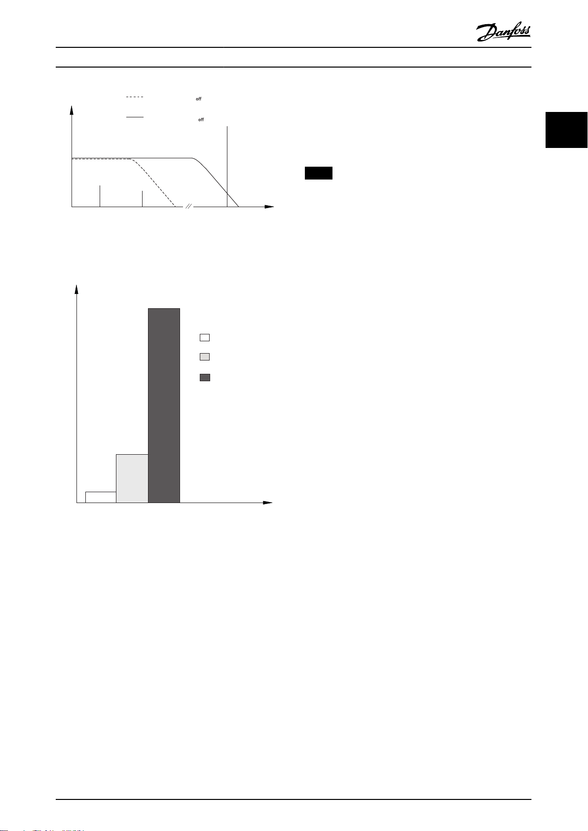
图 2.40
X 轴显示了 I
断开并使变频器跳闸之前的时间(秒)。曲线显示了额定
速度下、2 倍额定速度下以及 0.2 倍额定速度下的特
性。
在较低速度下,因为电动机的冷却能力降低,ETR 会在较
低热量水平下断开。它以这种方式防止电动机在低速下过
热。ETR 功能根据实际电流和速度计算电动机温度。计算
出的温度作为读出参数可在
看到。
所示。
图 2.40 ETR
和额定 I
motor
的比。Y 轴显示了 ETR
motor
参数 16-18 电动机发热
中
2.11.1 电机热保护
为避免对应用造成严重损害,变频器提供了若干专用功
能。
转矩极限
转矩极限可防止电机在任何速度下过载。转矩极限在
参
数 4-16 电动时转矩极限 和参数 4-17 发电时转矩极限
中控制。转矩极限警告跳闸前的时间在
极限跳闸延迟
电流极限
电流极限在
跳闸前的时间在
40 Danfoss A/S © 03/2019 全权所有。 MG06B541
中控制。
参数 4-18 电流极限
参数 14-24 转矩极限跳闸延迟
参数 14-25 转矩
中控制,电流极限警告
中控制。
Page 43
130BC435.13
CHASSIS/IP20
MADE BY DANFOSS IN CHINA
Danfoss A/S
6430 Nordborg
Denmark
T/C: FC-360HK37T4E20H2BXCDXXSXXXXAXBX
P/N: 134F2970 S/N: 691950A240
0.37 kW 0.5HP High Overload
IN: 3x380-480V 50/60Hz 1.24/0.99A
OUT: 3x0-Vin 0-500Hz 1.2/1.1A(Tamb. 45 C)
o
1
2
3
CAUTION:
SEE MANUAL
WARNING:
AND LOADSHARING BEFORE SERVICE
STORED CHARGE DO NOT TOUCH UNTIL 4 MIN. AFTER
DISCONNECTION
RISK OF ELECTRIC SHOCK-DUAL SUPPLY DISCONNECT MAINS
V LT
Automation Drive
www.danfoss.com
130BC437.11
1 2 3 4 5 6 7 8 9 10 11 12 13 14 15 16 17 18 19 20 21 22 23 24 25 26 27 28 29 30 31 32
F C - 3 6 0 H T 4 E 2 0 H 1 X X C D X X S X X X X A X B X
Q B
0
L
A
A
H 2
类型代码和选择 设计指南
3 类型代码和选择
3.1 订购
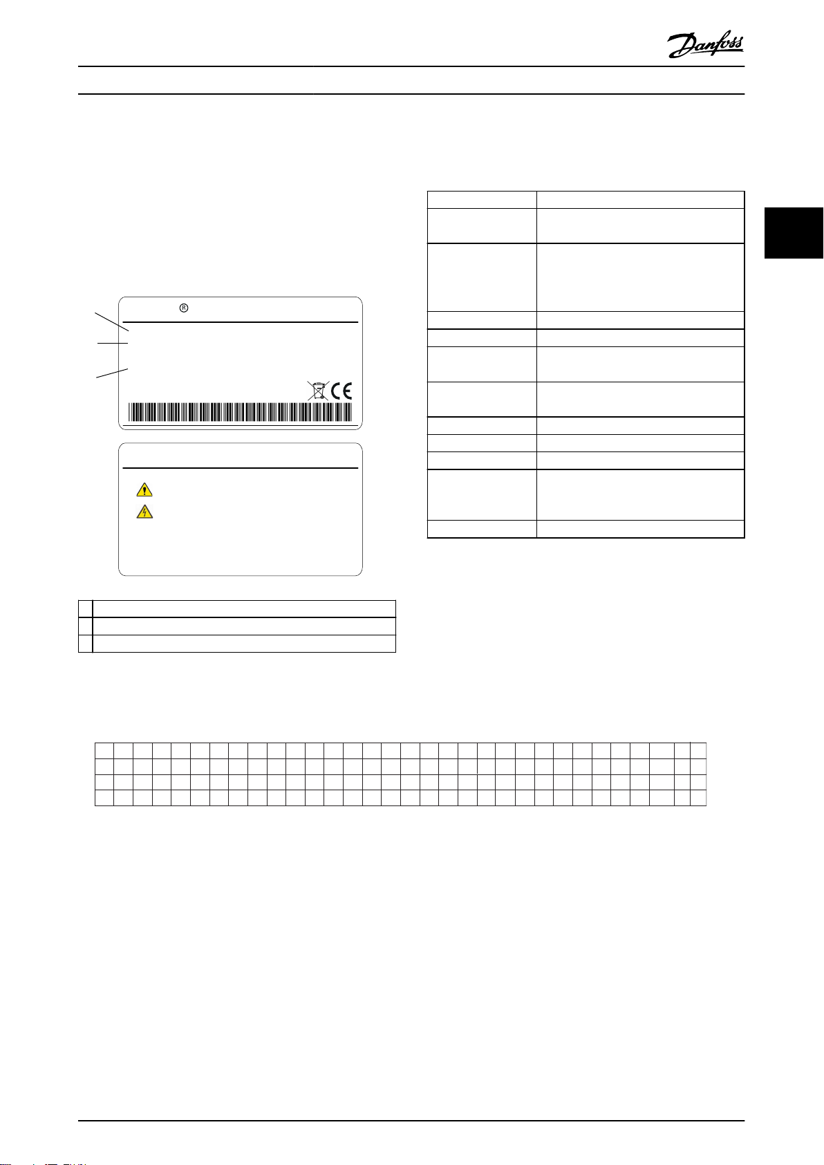
检查变频器铭牌上的功率规格、电压数据和过载数据,确
认设备是否与需求及订购信息相符。
1 类型代码
2 订购号
3 规格
图 3.1 铭牌 1 和 2
1–6: 产品名称
7: 过载
H: 重载
Q: 正常工况
1)
0.37–75 kW (0.5–100 hp)。例如:
8–10: 功率规格
K37: 0.37 kW2) (0.5 hp)
1K1: 1.1 kW (1.5 hp)
11 K: 11 kW (15 hp)
11–12: 电压等级 T4: 380–480 V 3 相
13–15: IP 等级 E20: IP20
16–17: RFI
H1: C2 等级
3)
H2: C3 等级
18: 制动斩波器
X: 否
B: 内置
4)
19: LCP X: 否
20: PCB 涂层 C: 3C3
21: 主电源端子 D: 负载共享
29–30: 嵌入式现场
总线
AX: 否
A0: PROFIBUS
AL: PROFINET
31–32: 选件 B BX: 无选件
表 3.1 类型代码: 各种不同功能和选项组合
有关选件和附件的信息,请参阅 VLT® AutomationDrive FC 360
设计指南 中的选件和附件 一节。
1) 正常工况仅有 11-75 kW (15–100 hp) 型号。正常工况无
PROFIBUS 和 PROFINET。
2) 有关所有功率规格的信息,请参阅章 4.1.1 主电源
3x380-480 V AC
3) H1 RFI 滤波器可用于 0.37–22 kW (0.5–30 hp)。
4) 0.37-22 kW (0.5–30 hp),带内置制动斩波器。30-75 kW
(40–100 hp),仅带外置制动斩波器。
3 3
图 3.2 类型代码字符串
MG06B541 Danfoss A/S © 03/2019 全权所有。 41
Page 44

类型代码和选择
VLT® AutomationDrive FC 360
3.2 订购号: 选件、附件以及备件
说明 订购号
VLT® Control Panel LCP 21
LCP 远程安装套件,包括 3 m 长的电缆
盖板,FC 360
33
图形化 LCP 适配器 132B0281
VLT® Control Panel LCP 102
VLT® Encoder Input MCB 102, FC 360
VLT® Resolver Input MCB 103, FC 360
用于 "MCB, J1, FC 360" 的端子盖 132B0263
用于 "MCB, J2, FC 360" 的端子盖 132B0265
用于 "MCB, J3, FC 360" 的端子盖 132B0266
用于 "MCB, J4, FC 360" 的端子盖 132B0267
用于 "MCB, J5, FC 360" 的端子盖 132B0268
去耦板安装套件,J1 132B0258
去耦板安装套件,J2 和 J3 132B0259
去耦板安装套件,J4 和 J5 132B0260
去耦板安装套件,J6 132B0284
去耦板安装套件,J7 132B0285
LCP 远程安装电缆,3 米(10 英尺)长 132B0132
VLT® Control Panel LCP 21 - RJ45 变频
器套件
表 3.2 选件和附件的订购号
132B0254
132B0102
132B0262
130B1107
132B0282
132B0283
132B0254
1) 2 种包装:6 件或 72 件。
2) 1 包 2 件。
1)
2)
1)
说明 订购号
标准控制盒 132B0255
控制盒(带有 PROFIBUS) 132B0256
控制盒(带有 PROFINET) 132B0257
用于 J1 0.37–1.5 kW (0.5–2 hp) 的风
扇 50x15 IP21
用于 J1 2.2 kW (3 hp) 的风扇 50x20
IP21
用于 J2 的风扇 60x20 IP21 132B0277
用于 J3 的风扇 70x20 IP21 132B0278
用于 J4 的风扇 92x38 IP21 132B0279
用于 J5 的风扇 120x38 IP21 132B0280
用于 J6 的风扇 92x38 IP21 132B0295
用于 J7 的风扇 120x38 IP21 132B0313
用于 J1–J5 的继电器和 RS485 标头 132B0264
功率控制卡,30 kW (40 hp) 132B0287
功率控制卡,37 kW (50 hp) 132B0290
功率控制卡,45 kW (60 hp) 132B0291
RFI 辅助卡,J6 132B0292
整流器模块,30–37 kW (40–50 hp) 132B0293
整流器模块,45 kW (60 hp) 132B0294
前盖,J6 132B0296
主电源端子,J6 132B0297
电机端子,J6 132B0298
直流总线端子,J6 132B0299
功率控制卡供电电缆,J6 132B0300
风扇加长电缆,J6 132B0301
隔离 RFI 箔,J6 132B0302
功率卡和母线支座,J6 132B0303
功率控制卡,55 kW (75 hp) 132B0305
功率控制卡,75 kW (100 hp) 132B0306
功率卡,J7 132B0307
RFI 辅助卡,J7 132B0308
整流器模块,J7 132B0309
带门驱动器电缆的 IGBT 模块,J7 132B0310
直流电容器,55 kW (75 hp) 132B0311
直流电容器,75 kW (100 hp) 132B0312
前盖,J7 132B0314
主电源,电机端子,55 kW (75 hp) 132B0315
直流总线端子,55 kW (75 hp) 132B0316
主电源,电机,直流总线端子,75 kW (100
hp)
温度探测电缆,J7 132B0318
功率控制卡供电电缆,J7 132B0319
风扇加长电缆,J7 132B0320
隔离 RFI 箔,J7 132B0321
隔离涌入箔,J7 132B0322
132B0275
132B0276
132B0317
表 3.3 备件订购号
42 Danfoss A/S © 03/2019 全权所有。 MG06B541
Page 45

类型代码和选择 设计指南
3.3 订购号: 制动电阻器
Danfoss 提供专为变频器设计的多种电阻器。了解制动电阻器的订购号,请参阅
章 2.9.4 通过制动功能进行控制
列出了制动电阻器的订购号。
3.3.1 订购号: 制动电阻器 (10%)
FC 360 P
T4 [kW] [Ω] [Ω] [Ω] [kW] 175Uxxxx [s]
HK37 0.37 890 1041.98 989 0.030 3000 120 1.5 0.3 139
HK55 0.55 593 693.79 659 0.045 3001 120 1.5 0.4 131
HK75 0.75 434 508.78 483 0.061 3002 120 1.5 0.4 129
H1K1 1.1 288 338.05 321 0.092 3004 120 1.5 0.5 132
H1K5 1.5 208 244.41 232 0.128 3007 120 1.5 0.8 145
H2K2 2.2 139 163.95 155 0.190 3008 120 1.5 0.9 131
H3K0 3 100 118.86 112 0.262 3300 120 1.5 1.3 131
H4K0 4 74 87.93 83 0.354 3335 120 1.5 1.9 128
H5K5 5.5 54 63.33 60 0.492 3336 120 1.5 2.5 127
H7K5 7.5 38 46.05 43 0.677 3337 120 1.5 3.3 132
H11K 11 27 32.99 31 0.945 3338 120 1.5 5.2 130
H15K 15 19 24.02 22 1.297 3339 120 1.5 6.7 129
H18K 18.5 16 19.36 18 1.610 3340 120 1.5 8.3 132
H22K 22 16 18.00 17 1.923 3357 120 1.5 10.1 128
H30K 30 11 14.6 13 2.6 3341 120 2.5 13.3 150
H37K 37 9 11.7 11 3.2 3359 120 2.5 15.3 150
H45K 45 8 9.6 9 3.9 3065 120 10 20 150
H55K 55 6 7.8 7 4.8 3070 120 10 26 150
H75K 75 4 5.7 5 6.6 3231 120 10 36 150
m (HO)
R
min
R
br. nom
R
rec
P
br avg
代号 周期 电缆横截
面积
[mm2]
1)
热敏
继电器
使用 R
时的最大
制动转矩
[A] [%]
。本节
3 3
rec
表 3.4 FC 360 - 主电源: 380–480 V (T4),10% 工作周期
1) 所有接线都必须符合相关国家和地方关于电缆横截面积和环境温度的法规。
MG06B541 Danfoss A/S © 03/2019 全权所有。 43
Page 46

类型代码和选择
VLT® AutomationDrive FC 360
3.3.2 订购号: 制动电阻器 (40%)
FC 360 P
T4 [kW] [Ω] [Ω] [Ω] [kW] 175Uxxxx [s]
33
HK37 0.37 890 1041.98 989 0.127 3101 120 1.5 0.4 139
HK55 0.55 593 693.79 659 0.191 3308 120 1.5 0.5 131
HK75 0.75 434 508.78 483 0.260 3309 120 1.5 0.7 129
H1K1 1.1 288 338.05 321 0.391 3310 120 1.5 1 132
H1K5 1.5 208 244.41 232 0.541 3311 120 1.5 1.4 145
H2K2 2.2 139 163.95 155 0.807 3312 120 1.5 2.1 131
H3K0 3 100 118.86 112 1.113 3313 120 1.5 2.7 131
H4K0 4 74 87.93 83 1.504 3314 120 1.5 3.7 128
H5K5 5.5 54 63.33 60 2.088 3315 120 1.5 5 127
H7K5 7.5 38 46.05 43 2.872 3316 120 1.5 7.1 132
H11K 11 27 32.99 31 4.226 3236 120 2.5 11.5 130
H15K 15 19 24.02 22 5.804 3237 120 2.5 14.7 129
H18K 18.5 16 19.36 18 7.201 3238 120 4 19 132
H22K 22 16 18.00 17 8.604 3203 120 4 23 128
H30K 30 11 14.6 13 11.5 3206 120 10 32 150
H37K 37 9 11.7 11 14.3 3210 120 10 38 150
H45K 45 8 9.6 9 17.5 3213 120 16 47 150
H55K 55 6 7.8 7 21.5 3216 120 25 61 150
H75K 75 4 5.7 5 29.6 3219 120 35 81 150
m (HO)
R
min
R
br. nom
R
rec
P
br avg
代号 周期 电缆横截
面积
[mm2]
1)
热敏
继电器
使用 R
时的最大
制动转矩
[A] [%]
rec
表 3.5 FC 360 - 主电源: 380–480 V (T4),40% 工作周期
1) 所有接线都必须符合相关国家和地方关于电缆横截面积和环境温度的法规。
44 Danfoss A/S © 03/2019 全权所有。 MG06B541
Page 47

规格 设计指南
4 规格
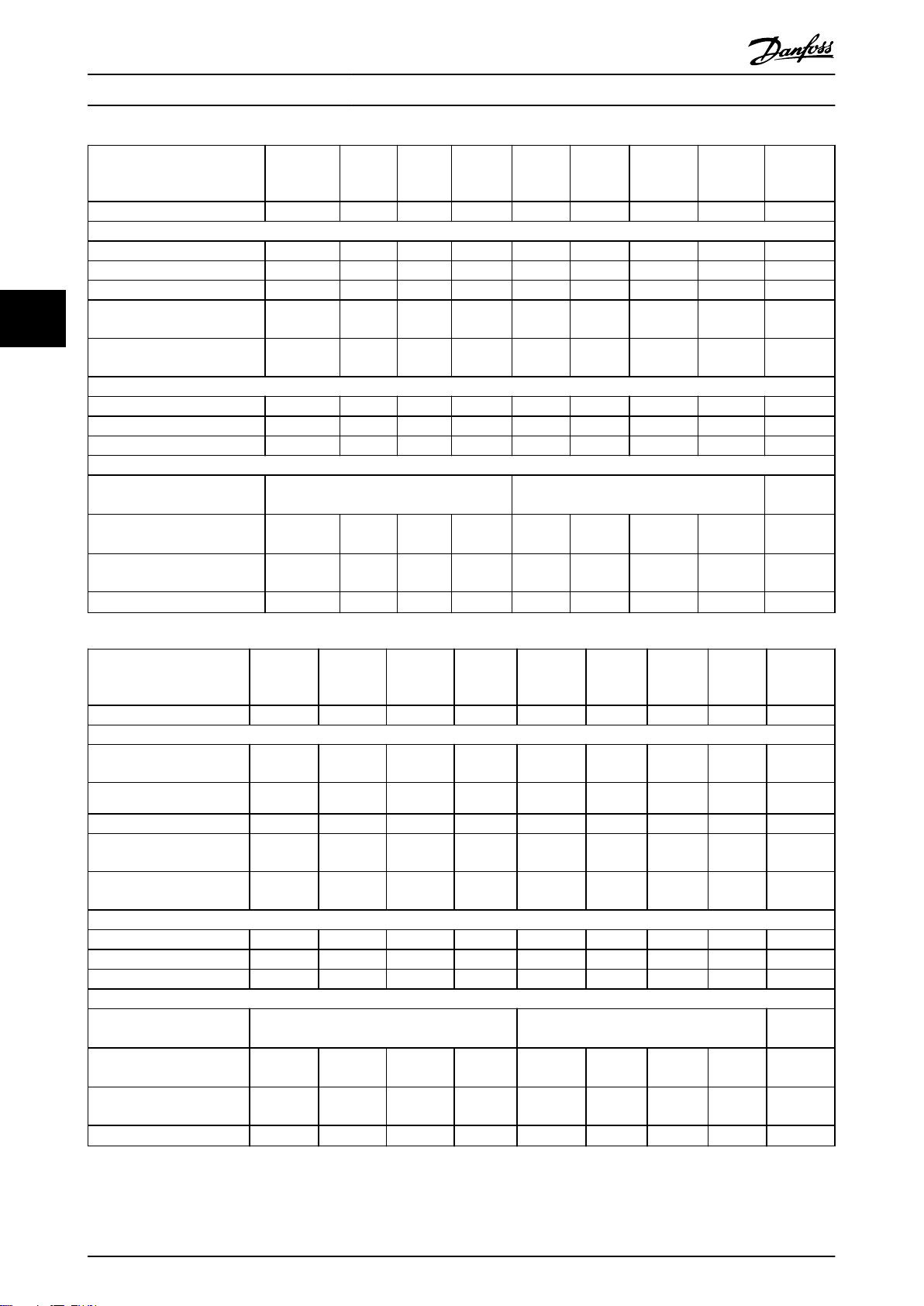
4.1 主电源 3x380-480 V AC
变频器典型主轴输出
[kW (hp)]
机箱防护等级 IP20 J1 J1 J1 J1 J1 J1 J2 J2 J2 J3
输出电流
主轴输出 [kW] 0.37 0.55 0.75 1.1 1.5 2.2 3 4 5.5 7.5
持续 (3x380-440V) [A] 1.2 1.7 2.2 3 3.7 5.3 7.2 9 12 15.5
持续 (3x441–480 V) [A] 1.1 1.6 2.1 2.8 3.4 4.8 6.3 8.2 11 14
间歇(60 秒过载)[A] 1.9 2.7 3.5 4.8 5.9 8.5 11.5 14.4 19.2 24.8
持续 kVA 值 (400 V AC) [kVA] 0.84 1.18 1.53 2.08 2.57 3.68 4.99 6.24 8.32 10.74
持续 kVA 值 (480 V AC) [kVA] 0.9 1.3 1.7 2.5 2.8 4.0 5.2 6.8 9.1 11.6
最大输入电流
持续 (3x380-440V) [A] 1.2 1.6 2.1 2.6 3.5 4.7 6.3 8.3 11.2 15.1
持续 (3x441–480 V) [A] 1.0 1.2 1.8 2.0 2.9 3.9 4.3 6.8 9.4 12.6
间歇(60 秒过载)[A] 1.9 2.6 3.4 4.2 5.6 7.5 10.1 13.3 17.9 24.2
附加规范
最大电缆横截面积(主电源、电机、
制动和负载共享)[mm2 (AWG)]
最大额定负载时的预计功率损耗
2)
[W]
重量 [kg (lb)],机箱防护等级为
IP20
效率 [%]
3)
HK37
0.37
(0.5)
20.88 25.16 30.01 40.01 52.91 73.97 94.81 115.5 157.54 192.83
2.3
(5.1)
96.2 97.0 97.2 97.4 97.4 97.6 97.5 97.6 97.7 98.0
HK55
0.55
(0.75)
2.3
(5.1)
HK75
0.75
(1)
2.3
(5.1)
H1K1
1.1
(1.5)
2.3
(5.1)
H1K5
1.5
(2)
2.3
(5.1)
4 (12)
H2K2
2.2
(3)
2.5
(5.5)
H3K0
3
(4)
3.6
(7.9)
H4K0
4
(5.5)
3.6
(7.9)
H5K5
5.5
(7.5)
3.6
(7.9)
H7K5
7.5
(10)
4.1
(9.0)
4 4
表 4.1 主电源 3x380–480 V AC - 重载
1)
MG06B541 Danfoss A/S © 03/2019 全权所有。 45
Page 48
规格
VLT® AutomationDrive FC 360
变频器典型主轴输出
[kW (hp)]
机箱防护等级 IP20 J4 J4 J5 J5 J6 J6 J6 J7 J7
输出电流
持续 (3x380-440V) [A] 23 31 37 42.5 61 73 90 106 147
持续 (3x441–480 V) [A] 21 27 34 40 52 65 77 96 124
间歇(60 秒过载)[A] 34.5 46.5 55.5 63.8 91.5 109.5 135 159 220.5
44
持续 kVA 值 (400 V AC)
[kVA]
持续 kVA 值 (480 V AC)
[kVA]
最大输入电流
持续 (3x380-440V) [A] 22.1 29.9 35.2 41.5 57 70.3 84.2 102.9 140.3
持续 (3x441–480 V) [A] 18.4 24.7 29.3 34.6 49.3 60.8 72.7 88.8 121.1
间歇(60 秒过载)[A] 33.2 44.9 52.8 62.3 85.5 105.5 126.3 154.4 210.5
附加规范
最大电缆规格(主电源、电
机、制动)[mm2 (AWG)]
最大额定负载时的预计功率损
2)
耗 [W]
重量 [kg (lb)],机箱防护等
级为 IP20
效率 [%]3)
H11K
11
(15)
15.94 21.48 25.64 29.45 42.3 50.6 62.4 73.4 101.8
17.5 22.4 28.3 33.3 43.2 54.0 64.0 79.8 103.1
289.53 393.36 402.83 467.52 630 848 1175 1250 1507
9.4 (20.7)
97.8 97.8 98.1 97.9 98.1 98.0 97.7 98.0 98.2
H15K
15
(20)
9.5
(20.9)
H18K
18.5
(25)
16 (6) 50 (1/0) 95 (3/0)
12.3
(27.1)
H22K
22
(30)
12.5
(27.6)
H30K
30
(40)
22.4
(49.4)
H37K
37
(50)
22.5
(49.6)
H45K
45
(60)
22.6
(49.8)
H55K
55
(75)
37.3
(82.2)
H75K
75
(100)
38.7
(85.3)
表 4.2 主电源 3x380–480 V AC - 重载
变频器典型主轴输出
[kW (hp)]
机箱防护等级 IP20 J4 J4 J5 J5 J6 J6 J6 J7 J7
输出电流
持续 (3x380-440V) [A] 23 31 37 42.5 61 73 90 106 147
持续 (3x441–480 V) [A]
间歇(60 秒过载)[A] 25.3 34.1 40.7 46.8 67.1 80.3 99 116.6 161.7
持续 kVA 值 (400 V AC)
[kVA]
持续 kVA 值 (480 V AC)
[kVA]
最大输入电流
持续 (3x380-440V) [A] 22.1 29.9 35.2 41.5 57 70.3 84.2 102.9 140.3
持续 (3x441–480 V) [A] 18.4 24.7 29.3 34.6 49.3 60.8 72.7 88.8 121.1
间歇(60 秒过载)[A] 24.3 32.9 38.7 45.7 62.7 77.3 92.6 113.2 154.3
附加规范
最大电缆规格(主电源、电
机、制动)[mm2 (AWG)]
最大额定负载时的预计功率
损耗 [W]
重量 [kg (lb)],机箱防护
等级为 IP20
效率 [%]3)
2)
Q11K
11
(15)
21 27 34 40 52 65 77 96 124
15.94 21.48 25.64 29.45 42.3 50.6 62.4 73.4 101.8
17.5 22.4 28.3 33.3 43.2 54.0 64.0 79.8 103.1
289.53 393.36 402.83 467.52 630 848 1175 1250 1507
9.4
(20.7)
97.8 97.8 98.1 97.9 98.1 98.0 97.7 98.0 98.2
1)
Q15K
15
(20)
9.5
(20.9)
Q18K
18.5
(25)
16 (6) 50 (1/0) 95 (3/0)
12.3
(27.1)
Q22K
22
(30)
12.5
(27.6)
Q30K
30
(40)
22.4
(49.4)
Q37K
37
(50)
22.5
(49.6)
Q45K
45
(60)
22.6
(49.8)
Q55K
55
(75)
37.3
(82.2)
Q75K
75
(100)
38.7
(85.3)
表 4.3 主电源 3x380–480 V AC - 正常工况
1)
1) 重工况 = 150~160% 电流,持续 60 秒;正常工况 = 110% 电流,持续 60 秒。
2) 额定负载条件下的典型功率损耗,可能有 ±15% 偏差(容差因电压和电缆情况而异)。
46 Danfoss A/S © 03/2019 全权所有。 MG06B541
Page 49

规格 设计指南
这些值基于典型的电机效率(IE2/IE3 的分界线)。效率较低的电动机会增加变频器的功率损耗,而效率较高者可以减小功率损耗。
适用于变频器冷却的尺寸确定。如果开关频率高于默认设置,则功率损耗可能会上升。其中已包括 LCP 的功率消耗和控制卡的典型功率
消耗。其它选件和客户负载可能会使损耗增加达 30 W(尽管满载的控制卡、现场总线或插槽 B 选件一般只会带来 4 W 的额外损
耗)。
有关符合 EN 50598-2 的功率损耗数据,请参考 www.danfoss.com/vltenergyefficiency.
3) 对于 J1–J5 型机箱,使用 5 米屏蔽电机电缆在额定负载和额定频率下测量;对于 J6 和 J7 型机箱,使用 33 米屏蔽电机电缆
在额定负载和额定频率下测量。有关能效等级的信息,请参阅章 4 规格 中的环境条件 一节。. 有关部分负载损耗的信息,请参阅
www.danfoss.com/vltenergyefficiency.
4.2 一般规范
主电源(L1、L2、L3)
供电端子 L1, L2, L3
供电电压 380–480 V: -15% (-25%)1) 至 +10%
1) 变频器可在 -25% 输入电压的情况下运行,但性能会有所下降。如果输入电压为 -25%,变频器只能达到最大输出功
率的 75%;如果输入电压为 -15%,变频器只能达到最大输出功率的 85%。
当主电源电压比变频器的最低额定电源电压低 10% 时,将无法实现满转矩。
供电频率
主电源各相位之间的最大临时不平衡 额定供电电压的 3.0%
真实功率因数 (λ) ≥0.9 标称值(额定负载时)
位移功率因数 (cos ϕ) 接近 1 (>0.98)
打开输入电源 L1、L2、L3(上电)≤7.5 kW (10 hp)
打开输入电源 L1、L2、L3(上电)(功率为 11–75 kW (15–100 hp)) 最多 1 次/分钟
此设备适用于能够提供少于 5000 RMS 安培的均方根对称电流和最大电压为 480 V 的电路。
电机输出 (U, V, W)
输出电压 电源电压的 0 - 100%
U/f 模式下的输出频率(对于 AM 电机) 0–500 Hz
VVC+ 模式下的输出频率(对于 AM 电机)
VVC+ 模式下的输出频率(对于 PM 电机)
输出切换 无限制
加减速时间 0.01–3600 s
50/60 Hz ±5%
最多 2 次/分钟
0–200 Hz
0–400 Hz
4 4
转矩特性
启动转矩(高过载) 最大 160%,持续 60 秒
过载转矩(高过载) 最大 160%,持续 60 秒
启动转矩(正常过载) 最大 110%,持续 60 秒
过载转矩(正常过载) 最大 110%,持续 60 秒
1)2)
1)2)
1)2
1)2
启动电流 最大 200%,持续 1 秒
VVC+中的转矩升高时间(与 f
sw
无关)
最长 50 ms
1) 相对于额定转矩的百分比。对于 11–75 kW (15–100 hp) 变频器,该值为 150%。
2) 每 10 分钟一次。
电缆的长度和横截面积
1)
最大电机电缆长度,屏蔽 50 m (164 ft)
0.37–22 kW (0.5–30 hp): 75 m (246 ft), 30–75 kW (40–100 hp): 100 m (328
最大电机电缆长度,非屏蔽
ft)
控制端子的最大横截面积(柔性/刚性电线) 2.5 mm2/14 AWG
控制端子电缆的最小横截面积 0.55 mm2/30 AWG
1) 关于电源电缆,请参阅表 4.1 至表 4.3。
数字输入
可编程数字输入 7
端子号 18, 19, 271), 291), 31, 32, 33
逻辑 PNP 或 NPN
电压水平 0–24 V DC
MG06B541 Danfoss A/S © 03/2019 全权所有。 47
Page 50

Mains
Functional
isolation
PELV isolation
Motor
DC Bus
High
voltage
Control
+24 V
RS-485
18
31
130BD310.10
规格
VLT® AutomationDrive FC 360
电压水平,逻辑 0 PNP < 直流 5 V
电压水平,逻辑 1 PNP >直流 10 V
电压水平,逻辑 0 NPN >直流 19 V
电压水平,逻辑 1 NPN < 直流 14 V
最高输入电压 28 V 直流
脉冲频率范围 4 Hz–32 kHz
(工作周期)最小脉冲宽度 4.5 ms
输入电阻,R
44
1) 也可以将端子 27 和 29 设为输出。
i
大约 4 kΩ
模拟输入
模拟输入的数量 2
端子号 53, 54
模式 电压或电流
模式选择 软件
电压水平 0–10 V
输入电阻,R
i
大约 10 kΩ
最大电压 -15 至 +20 V
电流水平 0/4 到 20 mA(可调节)
输入电阻,R
i
大约 200 Ω
最大电流 30 mA
模拟输入的分辨率 11 比特
模拟输入的精度 最大误差为满量程的 0.5%
带宽 100 Hz
模拟输入与供电电压 (PELV) 以及其它高电压端子之间都是绝缘的。
图 4.1 模拟输入
注意
高海拔
当安装地点的海拔超过 2000 米(6562 英尺)时,请联系 Danfoss 热线咨询 PELV 事宜。
脉冲输入
可编程脉冲输入 2
脉冲端子号 29, 33
端子 29、33 的最大频率 32 kHz(推挽驱动)
端子 29、33 的最大频率 5 kHz(开放式集电极)
端子 29 和 33 的最小频率 4 Hz
电压水平 请参阅“数字输入”一节
最高输入电压 28 V 直流
输入电阻,R
脉冲输入精度 最大误差: 全范围的 0.1 %
48 Danfoss A/S © 03/2019 全权所有。 MG06B541
i
大约 4 kΩ
Page 51

规格 设计指南
模拟输出
可编程模拟输出的数量 2
端子号 45, 42
模拟输出的电流范围 0/4–20 mA
模拟输出端和公共端间最大电阻器负载
模拟输出精度 最大误差: 满量程的 0.8%
模拟输出分辨率 10 比特
500 Ω
模拟输出与供电电压 (PELV) 以及其他高电压端子都是绝缘的。
控制卡,RS485 串行通讯
端子号 68 (P,TX+, RX+), 69 (N,TX-, RX-)
端子号 61 端子 68 和 69 的公共端
RS-485 串行通讯电路与供电电压 (PELV) 是电绝缘的。
数字输出
可编程数字/脉冲输出 2
端子号 27, 29
数字/频率输出的电压水平 0–24 V
最大输出电流(汲入电流或供应电流) 40 mA
频率输出的最大负载
频率输出的最大电容负载 10 nF
频率输出的最小输出频率 4 Hz
频率输出的最大输出频率 32 kHz
频率输出精度 最大误差: 全范围的 0.1 %
频率输出分辨率 10 比特
1 kΩ
1) 端子 27 和 29 也可以被设置为输入端子。
数字输出与供电电压 (PELV) 以及其他高电压端子之间都是电绝缘的。
控制卡,24 V 直流输出
端子号 12
最大负载 100 mA
24 V 直流电源与供电电压 (PELV) 是电绝缘的,但与模拟和数字的输入和输出有相同的电势。
4 4
1)
继电器输出
可编程继电器输出 2
继电器 01 和 02 01-03(常闭)、01-02(常开)、04-06(常闭)、04-05(常开)
01–02/04–05(常开)时的最大端子负载 (AC-1)1)(电阻性负载) 250 V AC,3 A
01–02/04–05(常开)时的最大端子负载 (AC-15)1)(cosφ 0.4 时的电感性负载)
01–02/04–05(常开)时的最大端子负载 (DC-1)1) (电阻性负载) 30 V DC,2 A
01–02/04–05(常开)时的最大端子负载 (DC-13)1)(电感性负载) 24 V 直流,0.1 A
01–03/04–06(常闭)时的最大端子负载 (AC-1)1)(电阻性负载) 250 V AC,3 A
01–03/04–06(常闭)时的最大端子负载 (AC-15)1)(cosφ 0.4 时的电感性负载)
01–03/04–06(常闭)时的最大端子负载 (DC-1)1)(电阻性负载) 30 V DC,2 A
01–03(常闭)、01–02(常开)时的最小端子负载 直流 24 V 10 mA,交流 24 V 20 mA
250 V AC, 0.2 A
250 V AC, 0.2 A
1) IEC 60947 t 4 和 5。
继电器的触点通过增强的绝缘措施与电路的其余部分电绝缘。
继电器可在不同负载(电阻性负载或电感性负载)上使用,具有不同生命周期。该生命周期取决于特定负载的配置。
控制卡,+10 V 直流输出
端子号 50
输出电压
最大负载 15 mA
10.5 V ±0.5 V
10 V 直流电源与供电电压 (PELV) 以及其他高电压端子都是绝缘的。
MG06B541 Danfoss A/S © 03/2019 全权所有。 49
Page 52

规格
控制特性
输出频率为 0-500 Hz 时的分辨率
系统响应时间(端子 18、19、27、29、32、33)
速度控制范围(开环) 1:100 同步速度
速度精度(开环)
速度精确度(闭环)
所有控制特性都基于 4 极异步电机。
VLT® AutomationDrive FC 360
±0.003 Hz
≤2 ms
额定速度的 ± 0.5%
额定速度的 ± 0.1%
44
环境条件
机箱规格 J1–J7 IP20
振动测试,所有机箱规格 1.0 g
相对湿度 5–95% (IEC 721-3-3); 工作环境中为 3K3 类(无冷凝)
腐蚀性环境(IEC 60068-2-43) H2S 测试
符合 IEC 60068-2-43 H2S 标准的测试方法(10 天)
环境温度(在 60 AVM 开关模式下)
- 降容
- 某些功率下的额定连续输出电流
- 在连续输出电流时
满负载运行时的最低环境温度
降低性能运行时的最低环境温度
存放/运输时的温度
不降容情况下的最高海拔高度 1000 m (3281 ft)
降容情况下的最大海拔高度 3000 m (9843 ft)
EN 61800-3、EN 61000-3-2、EN 61000-3-3、EN 61000-3-11、
EMC 标准,辐射
EMC 标准,抗扰性
能效等级
1) 请参考章 4.7 特殊条件 以了解:
2) 对于 VLT® AutomationDrive FC 360 的 PROFIBUS 和 PROFINET 型号,为防止控制卡温度过高,请在环境温度超过
45 °C (113 °F) 时避免数字/模拟 I/O 满载。
3) 根据 EN50598-2 在以下情况下确定:
3)
环境温度升高时的降容。
•
高海拔时的降容。
•
额定负载。
•
90% 额定频率。
•
开关频率出厂设置。
•
开关模式出厂设置。
•
EN 61000-3-12、EN 61000-6-3/4、EN 55011、IEC 61800-3
EN 61000-4-3、EN 61000-4-4、EN 61000-4-5、EN 61000-4-6
-25 至 +65/70 °C(-13 至 +149/158 °F)
EN 61800-3、EN 61000-6-1/2、EN 61000-4-2、
最高 55 °C (131 °F)
最高 50 °C (122 °F)
最高 45 °C (113 °F)
0 °C (32 °F)
-10 °C (14 °F)
Kd 类
1)2)
IE2
控制卡性能
扫描间隔 1 ms
保护与功能
电子热敏式电动机过载保护。
•
通过监测散热片的温度,可以确保变频器在温度达到某个预定义的水平时将跳闸。除非散热片温度下降到温度极
•
限以下,否则,无法复位过载温度。
变频器具有电动机端子 U、V 和 W 发生短路时的保护功能。
•
如果主电源发生缺相,变频器将跳闸或发出警告(取决于负载和参数设置)。
•
对中间电路电压的监测确保变频器在中间电路电压过低或过高时会跳闸。
•
变频器在电机端子 U、V 和 W 上有接地故障保护。
•
50 Danfoss A/S © 03/2019 全权所有。 MG06B541
Page 53
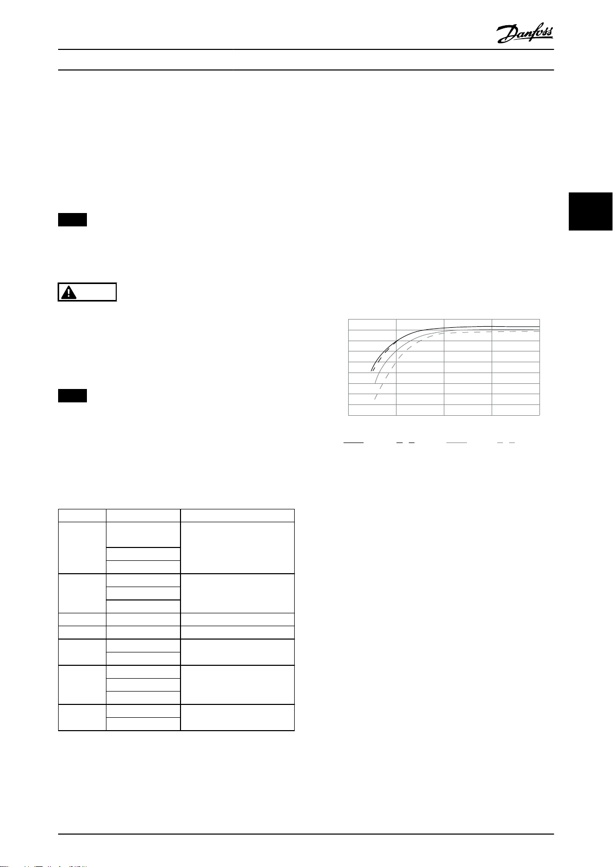
1.0
0.99
0.98
0.97
0.96
0.95
0.93
0.92
0% 50% 100% 200%
0.94
Relative Eciency
130BB252.11
1.01
150%
% Speed
100% load 75% load 50% load 25% load
规格 设计指南
4.3 熔断器
建议在供电侧使用熔断器和/或断路器,以便在变频器内部
的组件发生故障时防止维修人员受伤和设备损坏(第一故
障)。
支路保护
设备、开关装置和机器中的所有支路都必须根据国家/国际
法规配备短路保护和过电流保护。
注意
这些建议不包括 UL 标准所要求的支路保护。
表 4.4
中列出了经过测试的建议的熔断器。
警告
可能导致人身伤害和设备损坏
如果出现故障或未遵循建议,则可能造成人员危险以及变
频器和其他设备损坏。
根据建议选择熔断器。可以将变频器可能遭受的
•
损害限制在内部。
注意
必须使用熔断器或断路器,确保符合 IEC 60364 标准以
获得 CE 认证。
4.4
变频器效率 (η
效率
VLT
)
变频器的负载对其效率基本没有影响。一般来说,无论电
动机提供的是额定主轴转矩还是该值的 75%(在部分负载
的情况下),在额定电动机频率 f
下的效率都是相同
M,N
的。
这还意味着,即使选择了其它的 U/f 特性,变频器的效
率也不会更改。
但 U/f 特性会影响电动机的效率。
如果开关频率值设置为高于默认值,则效率会稍微降低。
如果主电源电压为 480 V,或电动机电缆超过 30 米长,
效率也会稍微降低。
变频器效率计算
根据
图 4.2
可以计算变频器在不同负载下的效率。本图中
的因数必须与规格表中所列的特定效率因数相乘:
4 4
Danfoss 建议在能够提供 100,000 A
380–480 V 电路(取决于变频器的额定电压)上使用
表 4.4
中列出的熔断器。在采用正确熔断器的情况下,变
频器的额定短路电流 (SCCR) 为 100000 A
机箱规格 功率 [kW (hp)] 通过 CE 认证的熔断器
0.37–1.1 (0.5–
J1
J2
J3 7.5 (10) gG-32
J4 11–15 (15–20) gG-50
J5
J6
J7
表 4.4 CE 熔断器,380–480 V,机箱类型 J1–J7
MG06B541 Danfoss A/S © 03/2019 全权所有。 51
1.5)
1.5 (2)
2.2 (3)
3.0 (4)
5.5 (7.5)
18.5 (25)
22 (30)
30 (40)
45 (60)
55 (75)
75 (100)
(对称)电流的
rms
。
rms
gG-10
gG-254.0 (5.5)
gG-80
gG-12537 (50)
aR-250
图 4.2 典型效率曲线
电动机效率 (η
MOTOR
)
连接到变频器的电机的效率取决于磁化级别。一般来说,
效率的高低与电网的运行状况直接相关。电动机的效率由
电动机的类型决定。
在额定转矩的 75–100% 的范围内,无论是由变频器控制
还是直接由主电源供电,电机效率几乎保持不变。
在较小的电动机中,U/f 特性对效率的影响可以忽略。但
是,如果电机功率大于 11 kW (15 hp) ,作用将比较明
显。
一般地说,开关频率并不影响小型电动机的效率。功率大
于等于 11 kW (15 hp) 的电机可以改进其效率(提高
1-2%),原因是,在高开关频率下,电机电流的正弦波形
几乎完美。
系统效率 (η
用变频器的效率 (η
SYSTEM
)
) 乘以电机的效率 (η
VLT
MOTOR
) 就能
计算出系统的效率:
η
SYSTEM
= η
VLT
x η
MOTOR
Page 54

规格
VLT® AutomationDrive FC 360
4.5 声源性噪音
变频器的声源性噪音有 3 个来源:
直流中间电路线圈。
•
内置风扇。
•
射频干扰滤波器的扼流装置。
•
在距离设备 1 米(3.3 英尺)处测得的典型值为:
44
机箱规格
J1 (0.37–2.2 kW/
0.5–3.0 hp)
J2 (3.0–5.5 kW/
4.0–7.5 hp)
J3 (7.5 kW/10 hp)
J4 (11–15 kW/15–
20 hp)
J5 (18.5–22
kW/25–30 hp)
J6 (30–45 kW/40–
60 hp)
J7 (55–75 kW/75–
100 hp)
表 4.5 测得的典型值
1) 对于 J1–J3,风扇速度是固定的。
50% 风扇速度
[dBA]
1)
N.A.
1)
N.A.
1)
N.A.
52 66
57.5 63
56 71
63 72
风扇全速运行
[dBA]
51
55
54
电缆
长度
[m (ft)]
5 (16.4) 400 0.164 0.98 5.4
50 (164) 400 0.292 1.04 2.81
5 (16.4) 480 0.168 1.09 5.27
50 (164) 480 0.32 1.23 3.08
表 4.6 FC 360 的 dU/dt 数据,2.2 kW (3.0 hp)
电缆
长度
[m (ft)]
5 (16.4) 400 0.18 0.86 3.84
50 (164) 400 0.376 0.96 2.08
5 (16.4) 480 0.196 0.97 3.98
50 (164) 480 0.38 1.19 2.5
表 4.7 FC 360 的 dU/dt 数据,5.5 kW (7.5 hp)
电缆
长度
[m (ft)]
5 (16.4) 400 0.166 0.992 4.85
50 (164) 400 0.372 1.08 2.33
5 (16.4) 480 0.168 1.1 5.2
50 (164) 480 0.352 1.25 2.85
主电源
电压
[V]
主电源
电压
[V]
主电源
电压
[V]
升高时间
[μsec]
升高时间
[μsec]
升高时间
[μsec]
U
PEAK
[kV]
U
PEAK
[kV]
U
PEAK
[kV]
dU/dt
[kV/μsec]
dU/dt
[kV/μsec]
dU/dt
[kV/μsec]
dU/dt 条件
4.6
当变频器桥中的晶体管开/关时,电机电压会以 du/dt 的
比率升高,du/dt 取决于以下因素:
电机电缆类型。
•
电机电缆的横截面积。
•
电机电缆的长度。
•
电机电缆是否为屏蔽型。
•
电感。
•
固有电感稳定在由中间电路电压决定的水平之前,它首先
在电动机电压中产生过冲 U
U
可影响电机的使用寿命。如果峰值电压过高,则没有
PEAK
。升高时间和峰值电压
PEAK
相位线圈绝缘措施的电机会受到影响。电机电缆越长,升
高时间就越长,峰值电压就越高。
IGBT 的开/关操作会在电机端子上产生峰值电压。FC 360
符合 IEC 60034-25 中有关适用于通过变频器进行控制的
电机的要求。FC 360 还符合 IEC 60034-17 中有关通过
变频器进行控制的标准电机的规定。
在电机端子侧测量以下 dU/dt 数据:
表 4.8 FC 360 的 dU/dt 数据,7.5 kW (10 hp)
电缆
长度
[m (ft)]
5 (16.4) 400 0.224 0.99 3.54
50 (164) 400 0.392 1.07 2.19
5 (16.4) 480 0.236 1.14 3.87
50 (164) 480 0.408 1.33 2.61
表 4.9 FC 360 的 dU/dt 数据,15 kW (20 hp)
电缆
长度
[m (ft)]
5 (16.4) 400 0.272 0.947 2.79
50 (164) 400 0.344 1.03 2.4
5 (16.4) 480 0.316 1.01 2.56
50 (164) 480 0.368 1.2 2.61
表 4.10 FC 360 的 dU/dt 数据,22 kW (30 hp)
主电源
电压
[V]
主电源
电压
[V]
升高时间
[μsec]
升高时间
[μsec]
U
PEAK
[kV]
U
PEAK
[kV]
dU/dt
[kV/μsec]
dU/dt
[kV/μsec]
52 Danfoss A/S © 03/2019 全权所有。 MG06B541
Page 55

0%
0 2 4 6 8 10 12 14 16
10%
20%
30%
40%
50%
60%
70%
80%
90%
100%
Switching Frequency [kHz]
Output Current
45C
50C
55C
130BG247.10
(1)
(2)
规格 设计指南
电缆
长度
[m (ft)]
5 (16.4) 400 0.212 0.81 3.08
53 (174) 400 0.294 0.94 2.56
5 (16.4) 480 0.228 0.95 3.37
53 (174) 480 0.274 1.11 3.24
表 4.11 FC 360 的 dU/dt 数据,37 kW (50 hp)
电缆
长度
[m (ft)]
5 (16.4) 400 0.14 0.64 3.60
50 (164) 400 0.548 0.95 1.37
5 (16.4) 480 0.146 0.70 3.86
50 (164) 480 0.54 1.13 1.68
表 4.12 FC 360 的 dU/dt 数据,45 kW (60 hp)
电缆
长度
[m (ft)]
5 (16.4) 400 0.206 0.91 3.52
54 (177) 400 0.616 1.03 1.34
5 (16.4) 480 0.212 1.06 3.99
54 (177) 480 0.62 1.23 1.59
主电源
电压
[V]
主电源
电压
[V]
主电源
电压
[V]
升高时间
[μsec]
升高时间
[μsec]
升高时间
[μsec]
U
PEAK
[kV]
U
PEAK
[kV]
U
PEAK
[kV]
dU/dt
[kV/μsec]
dU/dt
[kV/μsec]
dU/dt
[kV/μsec]
4.7
特殊条件
在一些特殊条件下,如果变频器的运行会受到影响,则可
考虑降容。有时候,必须用手动方式执行降容。
另一些时候,变频器可以根据需要自动执行一定程度的降
容。降容可确保关键环节的性能,否则,这些环节可能导
致跳闸。
4.7.1 手工降容
必须根据下述因素执行手动降容:
气压 - 安装在海拔超过 1000 米(3281 英
•
尺)的位置。
电机速度 - 在定转矩应用中持续低速工作时
•
环境温度 – 超过 45 °C (113 °F),对于一些
•
类型,则为超过 50 °C (122 °F),有关详细信
息,请参阅
表 4.16
图 4.3 至图 4.9、表 4.15
。
和
4 4
表 4.13 FC 360 的 dU/dt 数据,55 kW (75 hp)
电缆
长度
[m (ft)]
5 (16.4) 400 0.232 0.81 2.82
50 (164) 400 0.484 1.03 1.70
5 (16.4) 480 0.176 1.06 4.77
50 (164) 480 0.392 1.19 2.45
表 4.14 FC 360 的 dU/dt 数据,75 kW (100 hp)
MG06B541 Danfoss A/S © 03/2019 全权所有。 53
主电源
电压
[V]
升高时间
[μsec]
U
PEAK
[kV]
dU/dt
[kV/μsec]
(1) 输出电流
(2) 开关频率 [kHz]
图 4.3 J1 降容曲线
Page 56

0%
0 2 4 6 8 10 12 14 16
10%
20%
30%
40%
50%
60%
70%
80%
90%
100%
Switching Frequency [kHz]
Output Current
45C
50C
55C
130BG248.10
(1)
(2)
0%
0 2 4 6 8 10 12 14 16
10%
20%
30%
40%
50%
60%
70%
80%
90%
100%
Switching Frequency [kHz]
Output Current
45C
50C
55C
130BG249.10
(1)
(2)
0%
0 2 4 6 8 10 12 14 16
10%
20%
30%
40%
50%
60%
70%
80%
90%
100%
Switching Frequency [kHz]
Output Current
45C
50C
55C
130BG250.10
(1)
(2)
0%
0 2 4 6 8 10 12 14 16
10%
20%
30%
40%
50%
60%
70%
80%
90%
100%
Switching Frequency [kHz]
Output Current
45C
50C
55C
130BG251.10
(1)
(2)
规格
VLT® AutomationDrive FC 360
44
(1) 输出电流
(2) 开关频率 [kHz]
图 4.4 J2 降容曲线
(1) 输出电流
(2) 开关频率 [kHz]
(1) 输出电流
(2) 开关频率 [kHz]
图 4.6 J4 降容曲线
(1) 输出电流
(2) 开关频率 [kHz]
图 4.5 J3 降容曲线
54 Danfoss A/S © 03/2019 全权所有。 MG06B541
图 4.7 J5 降容曲线
Page 57
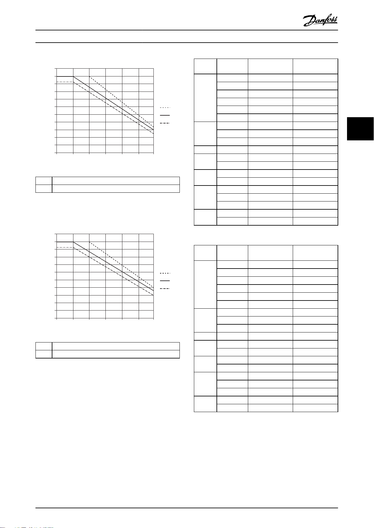
0%
0 2 4 6 8 10 12
10%
20%
30%
40%
50%
60%
70%
80%
90%
100%
Switching Frequency [kHz]
Output Current
45C
50C
55C
130BG252.10
(1)
(2)
110%
0%
0 2 4 6 8 10 12
10%
20%
30%
40%
50%
60%
70%
80%
90%
100%
Switching Frequency [kHz]
Output Current
45C
50C
55C
130BG253.10
(1)
(2)
110%
规格 设计指南
(1) 输出电流
(2) 开关频率 [kHz]
图 4.8 J6 降容曲线
机箱规格 功率规格
[kW (hp)]
45 °C 时的最大
输出电流
50 °C 时的最大
输出电流
0.37 (0.5) 1.2 1.2
0.55 (0.75) 1.7 1.7
0.75 (1.0) 2.2 2.2
J1
1.1 (1.5) 3.0 3.0
1.5 (2.0) 3.7 3.0
2.2 (3.0) 5.3 4.1
3 (4) 7.2 7.2
J2
4 (5.5) 9.0 9.0
5.5 (7.5) 12.0 10.2
J3 7.5 (10) 15.5 13.1
J4
J5
11 (15) 23.0 23.0
15 (20) 31.0 26.0
18.5 (25) 37.0 37.0
22 (30) 42.5 40.0
30 (40) 61 61
J6
37 (50) 73 73
45 (60) 90 77
J7
55 (75) 106 106
75 (100) 147 125
表 4.15 380 V 时的降容
4 4
(1) 输出电流
(2) 开关频率 [kHz]
图 4.9 J7 降容曲线
MG06B541 Danfoss A/S © 03/2019 全权所有。 55
机箱规格 功率规格
[kW]
45 °C 时的最大
输出电流
50 °C 时的最大
输出电流
0.37 (0.5) 1.1 1.1
0.55 (0.75) 1.6 1.6
0.75 (1.0) 2.1 2.1
J1
1.1 (1.5) 3.0 2.8
1.5 (2.0) 3.4 2.8
2.2 (3.0) 4.8 3.8
3 (4) 6.3 6.3
J2
4 (5.5) 8.2 8.2
5.5 (7.5) 11.0 9.4
J3 7.5 (10) 14.0 11.9
J4
J5
11 (15) 21.0 21.0
15 (20) 27.0 22.6
18.5 (25) 34.0 34.0
22 (30) 40.0 37.7
30 (40) 52 52
J6
37 (50) 65 65
45 (60) 77 76
J7
55 (75) 96 96
75 (100) 124 117
表 4.16 480 V 时的降容
Page 58
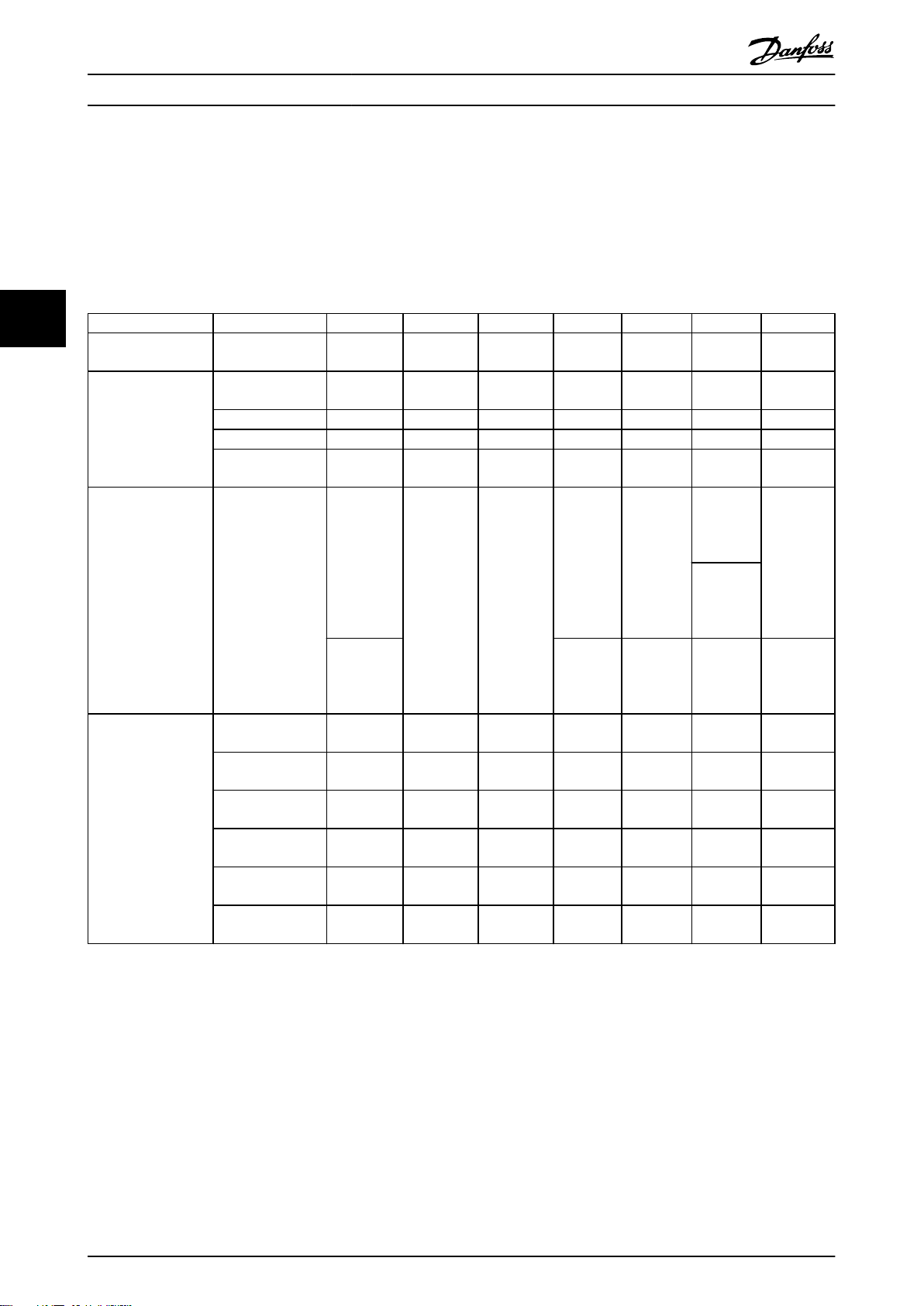
规格
VLT® AutomationDrive FC 360
4.7.2 自动降容
变频器会持续检查是否存在临界情况:
控制卡或散热片上的临界高温。
•
高电机负载。
•
作为对临界情况的反应,变频器会调整开关频率。
低电机转速。
•
触发保护信号(过压/欠压、过流、接地故障和短
•
路)。
4.8 机箱规格,额定功率和尺寸
44
安装孔 [mm (in)]
机箱规格 J1 J2 J3 J4 J5 J6 J7
功率规格
[kW (hp)]
尺寸
[mm (in)]
重量
[kg (lb)]
3 相
380–480 V
高度 A 210 (8.3)
宽度 B 75 (3.0) 90 (3.5) 115 (4.5) 133 (5.2) 150 (5.9) 233 (9.2) 308 (12.1)
深度 C 168 (6.6) 168 (6.6) 168 (6.6) 245 (9.6) 245 (9.6) 241 (9.5) 323 (12.7)
深度 C(带选件
B)
IP20
a 198 (7.8) 260 (10.2) 260 (10.2)
b 60 (2.4) 70 (2.8) 90 (3.5) 105 (4.1) 120 (4.7)
c 5 (0.2) 6.4 (0.25) 6.5 (0.26) 8 (0.32)
d 9 (0.35) 11 (0.43) 11 (0.43)
e 4.5 (0.18) 5.5 (0.22) 5.5 (0.22)
f 7.3 (0.29) 8.1 (0.32) 9.2 (0.36) 11 (0.43)
0.37–2.2
(0.5–3.0)
173 (6.8) 173 (6.8) 173 (6.8) 250 (9.8) 250 (9.8) 241 (9.5) 323 (12.7)
0.37–1.5
kW/
0.5–2.0
hp:
2.3 (5.1)
2.2 kW/3.0
hp:
2.5 (5.5)
3.0–5.5
(4.0–7.5)
272.5
(10.7)
3.6 (7.9) 4.1 (9.0)
7.5 (10)
272.5
(10.7)
11–15
(15–20)
317.5
(12.5)
11 kW/15
hp:
9.4
(20.7)
15 kW/20
hp:
9.5
(20.9)
297.5
(11.7)
12.4
(0.49)
6.8
(0.27)
18.5–22
(25–30)
410
(16.1)
18.5
kW/25 hp:
12.3
(27.1)
22 kW/30
hp:
12.5
(27.6)
390
(15.4)
7.8
(0.31)
12.6
(0.5)
7 (0.28)
11.2
(0.44)
30–45
(40–60)
515
(20.3)
30 kW/40
hp:
22.4
(49.4)
37 kW/50
hp:
22.5
(49.6)
45 kW/60
hp:
22.6
(49.8)
495
(19.49)
200
(7.87)
140 (5.5) 204 (8.0)
8.5
(0.33)
8.5
(0.33)
8.5
(0.33)
55–75
(75–100)
550 (21.7)
55 kW/75
hp:
37.3
(82.2)
75 kW/100
hp:
38.7
(85.3)
521 (20.5)
270
(10.63)
8.5 (0.33)
8.5 (0.33)
8.5 (0.33)
表 4.17 机箱规格,额定功率和尺寸
56 Danfoss A/S © 03/2019 全权所有。 MG06B541
Page 59
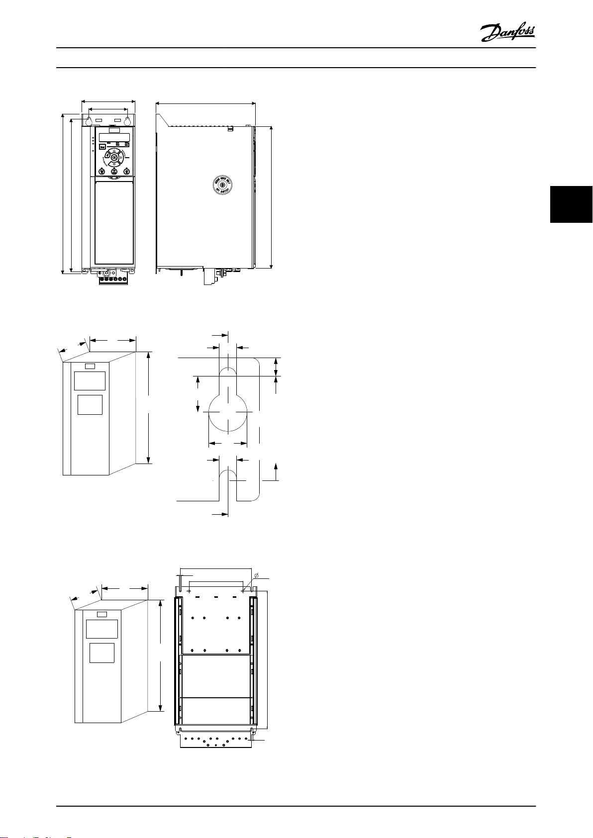
A
a
D
C
B
b
130BC449.10
C
a
b
130BA648.12
f
e
B
A
a
d
e
b
c
130BG254.10
f
e
c
b
a
C
B
A
b
d
规格 设计指南
图 4.10 尺寸
4 4
图 4.11 顶部和底部安装孔,J1–J5
图 4.12 顶部和底部安装孔,J6–J7
MG06B541 Danfoss A/S © 03/2019 全权所有。 57
Page 60

drop cable
RS485 安装和设置
VLT® AutomationDrive FC 360
5 RS485 安装和设置
5.1 简介
5.1.1 概述
RS485 是一种兼容多分支网络拓扑的 2 线总线接口。可以用总线方式或通过公共干线的分接电缆连接节点。1 个网络段
总共可以连接 32 个节点。
网络段由中继器来划分,请参阅
图 5.1
。
55
图 5.1 RS 485 总线接口
注意
安装在一个网络段中的中继器将充当该网络段的一个节
点。连接在给定网络中的每个节点必须拥有在所有网络段
中都具有唯一性的节点地址。
可以使用变频器的端接开关 (S801) 或偏置端接电阻网络
实现每个网络段两端的端接。总线接线必须始终采用屏蔽
的双绞线 (STP),并且遵守通用的最佳安装实践。
非常重要的一点是,在每个节点处都要保持屏蔽接地的低
阻抗性(包括在高频下)。因此,增大屏蔽层的接地面
积,例如借助电缆夹或导电的电缆密封管。有时,为了使
整个网络保持相同的地电位,必须应用电势均衡电缆,在
使用了长电缆的系统中尤其如此。
为避免阻抗不匹配,请在整个网络中使用同一类型的电
缆。将电机连接至变频器时,务必要使用屏蔽的电机电
缆。
电缆 屏蔽双绞线 (STP)
阻抗 [Ω] 120
最长长度为 1200 米(3937 英尺,包括分支
电缆长度[m
(ft)]
表 5.1 电缆规格
线路)。
工作站之间的最大距离为 500 米(1640 英
尺)。
5.1.2 网络连接
按下述方式将变频器连接至 RS485 网络(另请参阅
图 5.2
):
1. 将信号线连接至变频器主控制板的 68 (P+) 和
69 (N-) 号端子上。
2. 将电缆屏蔽层连接到电缆夹。
58 Danfoss A/S © 03/2019 全权所有。 MG06B541
Page 61

61 68 69
N
P
COMM. GND
130BB795.10
RS485 安装和设置 设计指南
注意
使用双绞屏蔽电缆可降低导体之间的噪声。
图 5.2 网络连接
5.1.3 硬件设置
要端接 RS485 总线,可使用变频器主控制板上的端接器
开关。
开关的出厂设置为 OFF(关闭)。
5.1.4 Modbus 通讯的参数设置
参数 功能
参数 8-30 协议
参数 8-31 地址
选择 RS485 接口使用的应用协议。
设置节点地址。
注意
地址范围取决于在
中选择的协议。
参数 8-30 协议
5.1.5 EMC 防范措施
为了让 RS485 网络实现无干扰工作,Danfoss 建议采取
以下 EMC 防范措施。
注意
请遵守相关的国家和地方法规,比如有关保护性接地的规
定。为避免电缆之间的高频噪声耦合,请保持 RS485 通
讯电缆远离电机电缆和制动电阻器电缆。通常而言,保持
200 毫米(8 英寸)的距离就已足够。最好使电缆间距尽
可能大,特别是当电缆平行安装且距离较长时。如果
RS485 电缆必须跨越电机电缆和制动电阻器电缆,则它与
后二者的角度应保持 90°。
5.2 FC 协议
5.2.1 概述
FC 协议(也称为 FC 总线或标准总线)是 Danfoss 标
准现场总线。它定义了一种符合主-从原理的访问技术来实
现现场总线通讯。
最多可以将一个主站和 126 个从站连接至总线。主站通
过报文中的地址字符来选择各个从站。如果没有事先请
求,从站自身不会传输任何消息。此外,各个从站之间无
法直接传输报文。通讯以半双工模式进行。
不能将主站的功能转移到另一节点上(单主站系统)。
5 5
参数 8-32 波特
率
参数 8-33 奇偶
校验/停止位
参数 8-35 最小
响应延迟
参数 8-36 最大
响应延迟
参数 8-37 最大
字节间延迟
设置波特率。
注意
默认波特率取决于在
中选择的协议。
设置奇偶校验和停止位数。
参数 8-30 协议
注意
默认选择取决于在
中选择的协议。
指定接收请求和传输响应之间的最小延迟时
间。该功能用于解决调制解调器工作延时问
题。
指定传输请求和接收回复之间的最大延迟时
间。
如果传输中断,可指定 2 个接收字节之间
的最大延时,以确保传输中断时能发生超
时。
参数 8-30 协议
注意
默认选择取决于在
中选择的协议。
表 5.2 Modbus 通讯的参数设置
MG06B541 Danfoss A/S © 03/2019 全权所有。 59
参数 8-30 协议
物理层是 RS485,因此需要利用变频器内置的 RS485 端
口。FC 协议支持不同的报文格式:
用于过程数据的 8 字节短格式。
•
16 字节长格式,其中还包含参数通道。
•
用于文本的格式。
•
5.2.2 带 Modbus RTU 的 FC
FC 协议提供了访问变频器的控制字和总线参考值的能
力。
Modbus 主站可以借助控制字来控制若干重要的变频器功
能:
启动。
•
以多种方式停止变频器:
•
- 惯性停止。
- 快速停止。
- 直流制动停止。
- 正常(变速)停止。
故障跳闸后复位。
•
以各种预置速度运转。
•
反向运转。
•
有效菜单的更改。
•
Page 62
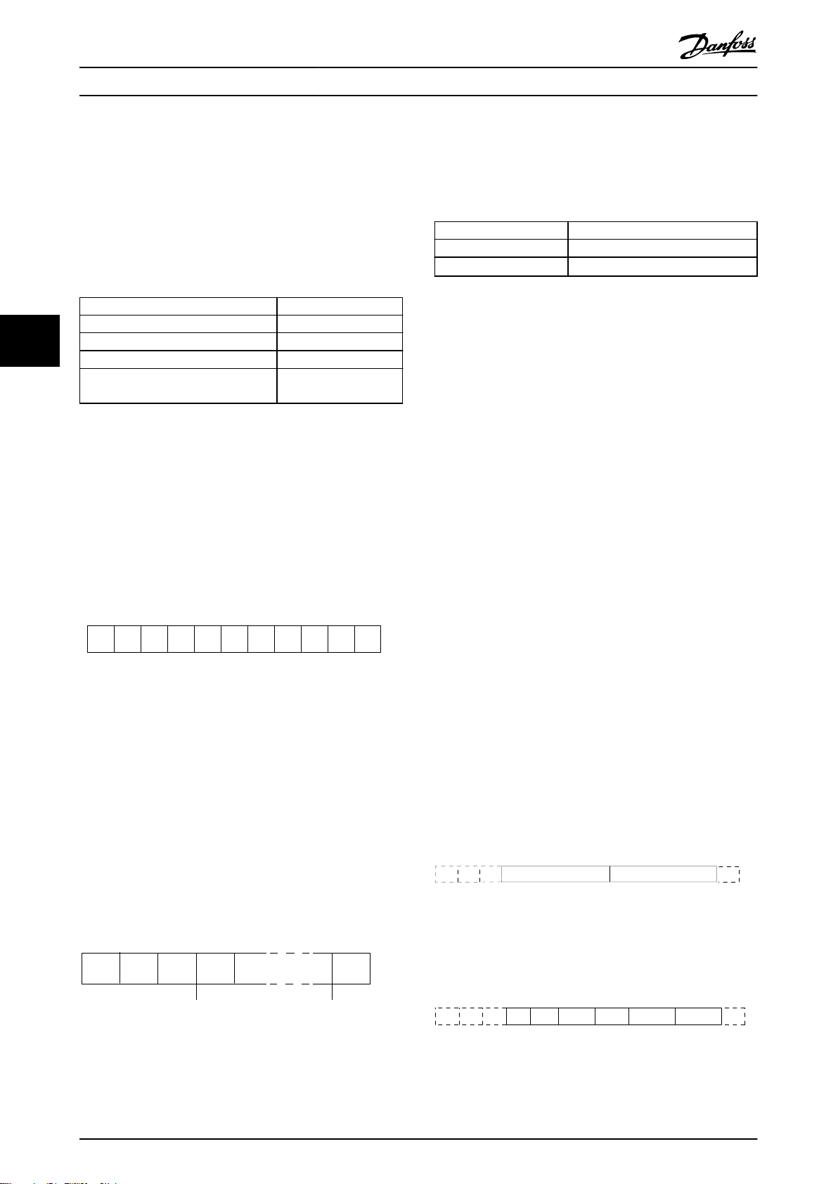
0 1 32 4 5 6 7
195NA036.10
Bit di
start
Parità Bit di
stop
STX LGE ADR D ATA BCC
195NA099.10
ADRLGESTX PCD1 PCD2 BCC
130BA269.10
PKE INDADRLGESTX PCD1 PCD2 BCC
130BA271.10
PWE
high
PWE
low
RS485 安装和设置
VLT® AutomationDrive FC 360
控制变频器内置的 2 个继电器。
•
5.4.3 报文长度 (LGE)
总线参考值通常用于速度控制。此外还可以访问参数,读
取其值,如果可能还可以将值写入其中。借助访问参数,
可以使用一系列的控制选项,包括在使用变频器的内部
报文长度是数据字节、地址字节 ADR 以及数据控制字节
BCC 三者之和。
PID 控制器时,控制变频器的给定值。
5.3 网络配置
要启用变频器的 FC 协议,请设置下述参数。
参数 设置
参数 8-30 协议
55
参数 8-31 地址
参数 8-32 波特率
参数 8-33 奇偶校验/停止位
FC
1–126
2400–115200
偶校验,1 个停止位
(默认)
4 个数据字节 LGE=4+1+1=6 个字节
12 个数据字节 LGE=12+1+1=14 个字节
含有文本的报文
表 5.4 报文长度
1) 10 表示固定字符数,而 n 是可变的(取决于文本的长
度)。
101)+n 字节
5.4.4 变频器地址 (ADR)
地址格式 1-126
表 5.3 启用协议的参数设置
5.4 FC 协议消息帧结构
5.4.1 字符(字节)的内容
从系统在对主系统的响应报文中会原封不动地将地址字节
位 7=1(使用 1-126 的地址格式)。
•
位 0-6=变频器地址 1-126。
•
位 0-6 = 0 广播。
•
发回。
每个字符的传输都是从该字符的起始位开始。随后传输 8
个数据位,对应一个字节。每个字符都通过奇偶校验位得
到保护。当该位符合奇偶校验时,它被设为 1。奇偶校验
是指 8 个数据位和该奇偶校验位中的 1 的个数在总体上
相等。字符以停止位作为结束,共包括 11 位。
5.4.5 数据 控制字节 (BCC)
校验和是以 XOR 函数形式计算的。收到报文的第一个字
节之前,所求出的校验和为 0。
图 5.3 字符内容
5.4.2 报文结构
每个报文都具有下列结构:
起始字符 (STX)=02 hex。
•
一个字节表示报文长度 (LGE)。
•
一个字节指明变频器地址 (ADR)。
•
接着是若干数据字节(数量不定,具体取决于电报的类
型)。
报文以一个数据控制字节 (BCC) 作为结束。
图 5.4 报文结构
5.4.6 数据字段
数据块的结构取决于报文类型。有 3 种类型的电报,每
种电报类型都同时适用于控制电报(由主⇒从)和响应电
报(由从⇒主)。
这 3 种报文类型是:
过程块 (PCD)
PCD 由 4 个字节(2 个字)的数据块组成,其中包括:
控制字和参考值(由主到从)。
•
状态字和当前输出频率(由从到主)。
•
图 5.5 过程块
参数块
参数块用于在主站和从站之间传输参数。数据块由 12 个
字节(6 个字)组成,并且还包含过程块。
图 5.6 参数块
60 Danfoss A/S © 03/2019 全权所有。 MG06B541
Page 63
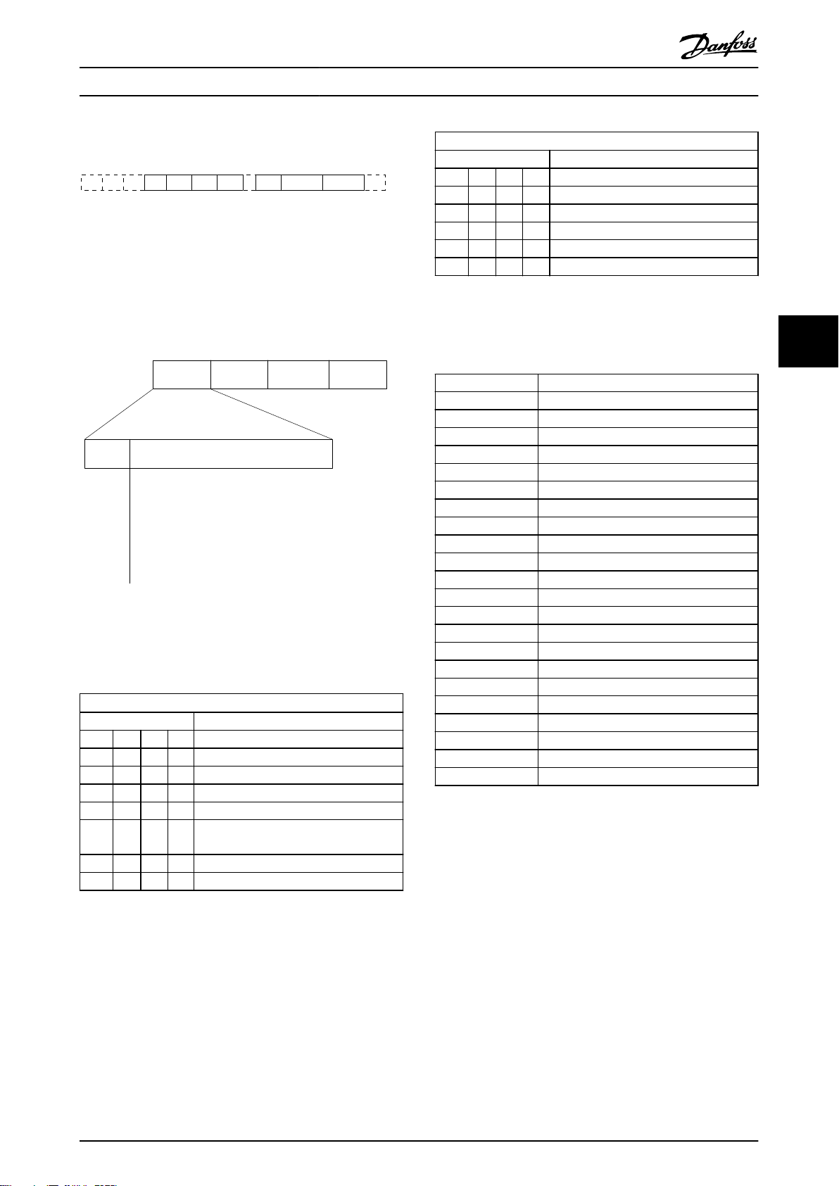
PKE IND
130BA270.10
ADRLGESTX PCD1 PCD2 BCCCh1 Ch2 Chn
15 14 13 12 11 10 9 8 7 6 5 4 3 2 1 0
130BB918.10
PKE IND
PWE
high
PWE
low
AK PNU
Parameter
commands
and replies
Parameter
number
RS485 安装和设置 设计指南
文本块
文本块用于通过数据块读取或写入文本。
图 5.7 文本块
5.4.7 PKE 字段
PKE 字段包含 2 个子字段:
参数命令和响应 (AK)。
•
参数号 (PNU)。
•
图 5.8 PKE 字段
第 12-15 位用于传输参数命令(由主到从)和将从站处
理过的响应传回主站。
主 ⇒ 从的参数命令。
位编号 参数命令
15 14 13 12
0 0 0 0 无命令。
0 0 0 1 读取参数值。
0 0 1 0 将参数值写入 RAM(字)。
0 0 1 1 将参数值写入 RAM(双字)。
1 1 0 1
1 1 1 0 将参数值写入 RAM 和 EEPROM(字)。
1 1 1 1 读取文本。
表 5.5 参数命令
将参数值写入 RAM 和 EEPROM(双
字)。
从⇒主的响应
位编号 响应
15 14 13 12
0 0 0 0 无响应。
0 0 0 1 传输的参数值(字)。
0 0 1 0 传输的参数值(双字)。
0 1 1 1 命令无法执行。
1 1 1 1 传输的文本。
表 5.6 响应
如果命令无法执行,从站发出响应消息“
执行
”,并在
故障代码 FC+ 规范
>100 –
表 5.7 从站报告
表 5.7
中给出下述故障报告:
0 非法参数编号。
1 参数无法被更改。
2 超出上限或下限。
3 子索引损坏。
4 无数组。
5 错误的数据类型。
6 未使用。
7 未使用。
9 描述元素不可用。
11 没有参数写访问权限。
15 没有可用文本。
17 不能在运行时进行。
18 其他错误。
100 –
130 此参数不能通过总线访问。
131 无法写入到出厂设置。
132 LCP 无访问权限。
252 未知查看器。
253 请求不受支持。
254 未知属性。
255 无错误。
5.4.8 参数号 (PNU)
第 0 - 11 位用于传输参数号。
AutomationDriveFC 360 编程指南
了有关参数的功能。
®
VLT
中的参数说明中定义
0111 命令无法
5 5
MG06B541 Danfoss A/S © 03/2019 全权所有。 61
Page 64

E19E H
PKE IND PWE
high
PWE
low
0000 H 0000 H 03E8 H
130BA092.10
RS485 安装和设置
VLT® AutomationDrive FC 360
5.4.9 索引 (IND)
同时使用索引和参数号,可以对具有索引的参数(如 )
进行读/写访问,例如
代码
。索引包含 2 个字节: 1 个低位字节和 1 个高位
字节。
只有低位字节可作为索引使用。
参数 15-30 报警记录: 故障错误
5.4.10 参数值 (PWE)
55
参数值块由 2 个字(4 个字节)组成,其值取决于定义
的命令 (AK)。当 PWE 块不包含任何值时,主站会提示您
输入参数值。要更改某个参数值(写操作),请将新值写
入 PWE 块中,然后从主站将相关消息发送到从站。
如果从站对参数请求(读命令)作出了响应,PWE 块中的
当前参数值将被传回给主站。如果参数包含多个数据选项
(例如
数据值来选择相应的值。串行通讯只能读取包含数据类型
9(文本字符串)的参数。
参数 15-40 FC 类型
含数据类型 9。
例如,可以读取
主电源电压范围。在传输(读)文本字符串时,报文的长
度是可变的,因为文本具有不同的长度。报文长度在报文
的第二个字节 (LGE) 中定义。使用文本传输时,可以用
索引字符表明这是一个读命令还是一个写命令。
参数 0-01 语言
到
参数 15-40 FC 类型
),则可通过在 PWE 块中输入
参数 15-53 功率卡序列号
中的设备规格和
包
换因数为 0.1,则表示被传输的值将被乘以 0.1。因此,
如果传输的值为 100,将被认为是 10.0。
转换索引 转换因数
74 3600
2 100
1 10
0 1
-1 0.1
-2 0.01
-3 0.001
-4 0.0001
-5 0.00001
表 5.9 转换
5.4.13 过程字 (PCD)
过程字的数据块分为两个部分,各有 16 位,它们总是按
照所定义的顺序出现。
PCD 1 PCD 2
控制报文(主⇒从控制字) 参考值
控制报文(从⇒主)状态字 当前的输出频率
表 5.10 过程字 (PCD)
5.5
示例
5.5.1 写入参数值
要通过 PWE 块读取文本,请将参数命令 (AK) 设为 F
(十六进制)。索引字符的高位字节必须为 4 。
将
参数 4-14 电机速度上限 [Hz]
将数据写入 EEPROM。
更改为 100 Hz。
5.4.11 变频器支持的数据类型
“无符号”数据类型,即在报文中没有运算符。
数据类型 说明
3 16 位整数
4 32 位整数
5 8 位无符号整数
6 16 位无符号整数
7 32 位无符号整数
9 文本字符串
表 5.8 数据类型
5.4.12 转换
编程指南
数形式传输。在传输小数时需要使用转换因数。
参数 4-12 电机速度下限 [Hz]
将最小频率预设为 10 Hz,则传输的值应是 100。如果转
包含每个参数的属性的说明。参数值只能以整
的转换因数为 0.1。要
PKE = E19E(十六进制)– 写入单字到
机速度上限 [Hz]
IND = 0000(十六进制)。
•
PWEHIGH = 0000(十六进制)。
•
PWELOW = 03E8(十六进制)。
•
数据值 1000,对应于 100 Hz,请参阅
换
。
相应的报文如
图 5.9 报文
:
图 5.9
章 5.4.12 转
。
参数 4-14 电
62 Danfoss A/S © 03/2019 全权所有。 MG06B541
Page 65

119E H
PKE
IND
PWE
high
PWE
low
0000 H 0000 H 03E8 H
130BA093.10
1155 H
PKE IND PWE
high
PWE
low
0000 H 0000 H 0000 H
130BA094.10
130BA267.10
1155 H
PKE
IND
0000 H 0000 H 03E8 H
PWE
high
PWE
low
RS485 安装和设置 设计指南
注意
参数 4-14 电机速度上限 [Hz]
EEPROM 中写入的参数命令为“E”。
上限 [Hz]
从站对主站的响应如
图 5.10 主站响应
是 19E(十六进制)。
图 5.10
5.5.2 读取参数值
在
参数 3-41 斜坡 1 加速时间
PKE=1155(十六进制)- 读取
时间
中的参数值:
IND = 0000(十六进制)。
•
PWE
= 0000(十六进制)。
•
•
图 5.11 报文
如果
站对主站的响应如
图 5.12 响应
3E8(十六进制)对应于 1000(十进制)。
坡 1 加速时间
参数 3-41 斜坡 1 加速时间
数
。
HIGH
PWE
= 0000 Hex。
LOW
参数 3-41 斜坡 1 加速时间
图 5.12
的转换索引为 -2,即 0.01。
是一个单字,用于在
参数 4-14 电机速度
所示。
中读取参数值
参数 3-41 斜坡 1 加速
的值为 10 秒,则从
所示。
的类型是
无符号 32 位整
参数 3-41 斜
5.6
Modbus RTU
5.6.1 预备知识
Danfoss 假设所安装的控制器支持本手册中介绍的接口,
并严格遵守在控制器和变频器中规定的所有要求和限制。
内置的 Modbus RTU(远程终端设备)可以与任何支持本
手册中定义的接口的控制器进行通讯。本说明假设用户完
全了解控制器的功能和限制。
5.6.2 概述
无论物理通讯网络为何种类型,本小节描述了控制器请求
访问另一台设备时使用的过程。这如何响应来自另一台设
备的请求,以及如何检测和报告错误。此外还建立了报文
字段布局和内容的公用格式。
在通过 ModBus RTU 网络进行通讯期间,协议将:
确定每个控制器将如何了解其设备地址。
•
如何识别发送给它的报文。
•
如何确定要采取的操作。
•
如何提取报文中所含的任何数据或其他信息。
•
如果要求回复,控制器将创建并发送回复报文。
控制器利用主从技术进行通讯,该技术仅允许主设备启动
事务(称为查询)。从设备可通过向主设备提供所请求的
数据,或按查询中请求的操作进行响应。
主站可以对单个从站进行寻址,或向所有从站发送广播报
文。从站会向对它们单独寻址的查询返回响应。但对来自
主站的广播查询则不予响应。
Modbus RTU 协议通过提供以下信息给主设备的查询建立
格式:
设备(或广播)地址。
•
定义所需操作的功能代码。
•
将发送的任何数据。
•
错误检查字段。
•
也可使用 Modbus 协议创建从站的响应报文。其中包含确
认所采取操作的字段、要返回的所有数据及错误检查字
段。如果在接收报文时发生错误,或者从站无法执行所请
求的操作,那么从站将返回一条错误消息。或者出现超
时。
5 5
MG06B541 Danfoss A/S © 03/2019 全权所有。 63
5.6.3 带有 Modbus RTU 的变频器
该变频器通过内置的 RS485 接口以 Modbus RTU 格式进
行通讯。Modbus RTU 提供了访问变频器的控制字和总线
参考值的能力。
Modbus 主站可以借助控制字来控制若干重要的变频器功
能:
Page 66

RS485 安装和设置
VLT® AutomationDrive FC 360
启动。
•
多种停止:
•
- 惯性停止。
- 快速停止。
- 直流制动停止。
- 正常(变速)停止。
故障跳闸后复位。
•
以各种预置速度运转。
•
反向运转。
•
55
总线参考值通常用于速度控制。此外还可以访问参数,读
取其值,如果可能还可以将值写入其中。借助访问参数,
可以使用一系列的控制选项,包括在使用变频器的内部
PID 控制器时,控制变频器的给定值。
更改有效菜单。
•
控制变频器的内置继电器。
•
5.7 网络配置
要在该变频器上启用 Modbus RTU,请设置下述参数:
参数 设置
参数 8-30 协议
参数 8-31 地址
参数 8-32 波特率
参数 8-33 奇偶校验/停止位
表 5.11 网络配置
Modbus RTU 消息帧结构
5.8
Modbus RTU
1–247
2400–115200
偶校验,1 个停止位(默认)
错误检查字段 循环冗余校验 (CRC)。
表 5.13 字节详情
5.8.2 Modbus RTU 报文结构
传输设备将 Modbus RTU 报文放入一个 开始和结束位置
已知的帧中。这样,即可在报文开始处指定接收设备,读
取地址部分,确定该报文要发送到哪台设备(或所有设
备,如果报文为广播型),并了解报文的完成时间。检测
到部分报文,因而产生错误。在每个字段中传输的字符必
须使用从 00–FF 的十六进制格式。变频器会持续监视网
络总线,即便在静止期间也是如此。接收到第一个字段
(地址字段)后,每个变频器或设备都会将其解码,以确
定被寻址的设备。编址为零的 Modbus RTU 报文是广播报
文。不允许响应广播报文。典型的报文帧如
示。
开始时) 地址 功能 数据 CRC 检查 终止
T1-T2-
T3-T4
表 5.14 典型 Modbus RTU 报文结构
8 位 8 位
N x 8
位
表 5.14
16 位
所
T1-T2-
T3-T4
5.8.3 启动/停止字段
报文以一个静止段开始。此段至少为 3.5 个字符间隔。
静止段为多个字符间隔,这可用所选网络波特率下的字符
间隔的倍数来实现(显示为启动 T1-T2-T3-T4)。所传输
的第一个字段为设备地址。在传输完最后一个字符后,紧
接着是一个类似的至少为 3.5 个字符间隔的段,它标志
着报文的结束。在此段之后可以开始新的报文。
5.8.1 简介
控制器被设置为在 Modbus 网络上使用 RTU(远程终端设
备)模式进行通讯,消息中的每个字节中都包含两个 4
位十六进制字符。各个字节的格式如
起始
位
表 5.12 各个字节的格式
编码系统 8 位,二进制、十六进制 0–9, A–F。
每个字节的位数
数据字节 停止/
在报文的每个 8 位字段中都包括 2 个十
六进制字符。
1 个起始位。
•
8 个数据位,最小有效位先发送。
•
1 个偶/奇校验位; 如果无奇偶校验,
•
则不存在位。
1 个停止位(如果使用奇偶校验);
•
如果无奇偶校验,则为 2 位。
表 5.12
所示。
停止
奇偶校
验
将整个报文帧作为连续的数据流传输。如果在帧结束之前
出现了超过 1.5 个字符间隔的静止段,则接收设备会丢
弃不完整的报文,并假设下一字节为新报文的地址字段。
类似地,如果新报文在上一条报文之后的 3.5 个字符间
隔内便开始,则接收设备会将其视为上一报文的延续。这
会导致超时(从站无响应),因为对于该组合报文而言,
最后的 CRC 字段中的值将无效。
5.8.4 地址字段
报文帧的地址字段包含 8 位。有效的从设备地址应介于
0–247(十进制) 范围内。为单台从设备分配的地址应
介于 1–247 的范围。0 预留给广播模式,这是所有从站
都认可的。主站通过将从站地址放入报文的地址字段,对
从站进行寻址。从站发送其响应时,会将自己的地址放在
此地址字段中,以使主站了解哪个从站在进行响应。
64 Danfoss A/S © 03/2019 全权所有。 MG06B541
Page 67

RS485 安装和设置 设计指南
5.8.5 功能字段
报文帧的功能字段包含 8 位。有效代码的范围为 1 FF。功能字段用于在主站和从站之间发送报文。从主设备
向从属设备发送报文时,功能代码字段将通知从属设备要
执行的操作类型。从属设备对主设备进行响应时,会使用
功能代码字段指示正常(无错)响应或发生了某种错误
(称为异常响应)。
对于正常响应,从属设备只重复原先的功能代码。对于异
常响应,从站会返回一个代码。该代码相当于原始的功能
代码,只不过其最大有效位被设为逻辑 1。此外,从属设
备还将一个唯一的代码放入响应报文的数据字段中。该代
码可通知主控制器发生了哪种错误,或异常的原因。另请
参阅
章 5.8.10 Modbus RTU 支持的功能代码
章 5.8.11 Modbus 异常代码
。
和
5.8.6 数据字段
数据字段是使用几组两个十六进制数字(范围在 00 至
FF 之间)构建的。这些数字都由一个 RTU 字符构成。从
主设备发送到从设备的报文的数据字段包含其他信息,从
属设备必须使用这些信息执行相应功能。
该信息可包括以下项目:
线圈或寄存器地址。
•
要处理的项目数量。
•
字段内的实际数据字节数。
•
5.8.7 CRC 检查字段
报文中包括一个错误检查字段,此字段的工作机制基于循
环冗余校验 (CRC) 方法。CRC 字段可检查整条报文的内
容。它的应用与用于报文的单个字符的任何奇偶校验方法
均无关。传输设备计算 CRC 值,然后将 CRC 作为最后一
个字段附加在报文中。接收设备会在接收报文过程中重新
计算 CRC,并将计算值与 CRC 字段中接收到的实际值相
比较。2 个值不相等将会导致总线超时。错误检查字段包
含一个 16 位二进制值,该值由两个 8 位字节组成。执
行之后,首先附加字段的低位字节,然后是高位字节。CRC
高位字节为报文中发送的最后一个字节。
5.8.8 线圈寄存器编址
在 Modbus 中,所有数据都是用线圈和保持寄存器来组织
的。线圈保持单个位,而保持寄存器则保持 2 字节字
(即 16 位)。Modbus 报文中的所有数据地址均从零开
始。数据项的第一个项目编号被编址为零。例如: 可编
程控制器中的线圈 1 在 Modbus 报文的数据地址字段中
被编址为线圈 0000。线圈 127(十进制)被编址为线圈
007EHEX(十进制的 126)。
保持寄存器 40001 在报文数据地址字段中被编址为寄存
器 0000。功能代码字段已指定某个保持寄存器操作。因
此,4XXXX 引用值是固有的。保持寄存器 40108 被编址
为寄存器 006BHEX(十进制的 107)。
线圈编号 说明 信号方向
1–16 变频器控制字(请参阅
17–32 变频 器速度或给定-值的 参考 范
围 0x0–0xFFFF (-200% ...
~200%)。
33–48 变频器状态字(请参阅
49–64 开环模式: 变频器输出频率。
闭环模式: 变频器反馈信号。
参数写入控制(由主到从)。
0 = 将参数变化写入变频器的
65
66–
65536
表 5.15 线圈寄存器
线圈 0 1
01 预置参考值,低位 (lsb)
02 预置参考值,高位 (msb)
03 直流制动 无直流制动
04 惯性停止 无惯性停止
05 快速停止 无快速停止
06 锁定频率 无锁定频率
07 加减速停止 启动
08 不复位 复位
09 无点动 点动
10 加减速 1 加减速 2
11 数据无效 数据有效
12 继电器 1 关 继电器 1 开
13 继电器 2 关 继电器 2 开
14 设置 lsb
15 –
16 无反向 反向
表 5.16 变频器控制字(FC 协议)
线圈 0 1
33 控制未就绪 控制就绪
34 变频器未就绪 变频器就绪
35 惯性停止 安全功能关闭
36 无报警 报警
37 未使用 未使用
38 未使用 未使用
39 未使用 未使用
40 无警告 警告
41 不在参考值下 在参考值下
42 手动模式 自动模式
43 超出频率范围 在频率范围内
44 已停止 运行
45 未使用 未使用
46 无电压警告 电压警告
47 不在电流极限内 电流极限
48 无热警告 热警告
表 5.17 变频器状态字(FC 协议)
RAM。
1 = 将参数变化写入变频器的 RAM
和 EEPROM。
预留。 –
表 5.16
表 5.17
) 由主到从
由主到从
)。 由从到主
由从到主
由主到从
5 5
MG06B541 Danfoss A/S © 03/2019 全权所有。 65
Page 68

RS485 安装和设置
VLT® AutomationDrive FC 360
总线地址总线
0 1 40001 预留
1 2 40002 预留
2 3 40003 预留
3 4 40004 自由 – –
4 5 40005 自由 – –
5 6 40006 Modbus 配置 读/写 (R/W) 仅限 TCP。预留给 Modbus TCP(
6 7 40007 最近的故障代码 只读 从参数数据库收到的故障代码,有关详细信息,请参考 WHAT 38295。
55
7 8 40008 最近的错误寄存器 只读 最近发生错误的寄存器的地址,有关详细信息,请参考 WHAT 38296。
8 9 40009 索引指针 读/写 (R/W) 要访问的参数的下标索引。有关详细信息,请参考 WHAT 38297。
9 10 40010
19 20 40020
29 30 40030
表 5.18 地址/寄存器
PLC 寄存器内容 访问 说明
寄存
1)
器
参数 0-01 语言
参数 0-02 电动机速
度单位
参数 0-03 区域性设
置
取决于参数
访问权限
取决于参数
访问权限
取决于参数
访问权限
–
–
–
预留给早期的 VLT® 5000 和 VLT® 2800 变频器。
预留给早期的 VLT® 5000 和 VLT® 2800 变频器。
预留给早期的 VLT® 5000 和 VLT® 2800 变频器。
参数 12-28 存储数据值
数 12-29 总是存储
参数 0-01 语言
为 Modbus 映射中的 pr 参数预留 20 个字节的空间。
- 存储在诸如 EEPROM 等位置内)。
(Modbus 寄存器 = 10 个参数编号)
和
参
参数 0-02 电动机速度单位
为 Modbus 映射中的 pr 参数预留 20 个字节的空间。
参数 0-03 区域性设置
为 Modbus 映射中的 pr 参数预留 20 个字节的空间。
1) 写入 Modbus RTU 报文的值必须为 1 或小于寄存器编号。例如,可通过在报文中写入值 0 来读取 Modbus 寄存器 1。
5.8.9 如何控制变频器
本节介绍了可以在 Modbus RTU 报文的功能字段和数据字
段中使用的代码。
5.8.10 Modbus RTU 支持的功能代码
Modbus RTU 支持在报文的功能字段中使用下述功能代
码:
功能 功能代码 (十六进制)
读取线圈 1
读取保持寄存器 3
写入单个线圈 5
写入单个寄存器 6
写入多个线圈 F
写入多个寄存器 10
获取通讯事件计数器 B
报告从站 ID 11
表 5.19 功能代码
功能 功能代码 子功能
代码
诊断 8 1 重新启动通讯。
2 返回诊断寄存器。
10 清空计数器和诊断寄存
11 返回总线消息计数。
12 返回总线通讯错误计数。
13 返回从站错误计数。
14 返回从站消息计数。
表 5.20 功能代码
5.8.11 Modbus 异常代码
有关异常代码响应消息的结构的完整说明,请参考
章 5.8.5 功能字段
代码 名称 含义
1 非法功能
。
查询中收到的功能代码对于该伺服设备
(或从设备)来说是不允许的操作。这可
能是因为该功能代码仅适用于更新的设
备,未在所选设备中实施。这可能还表明
该伺服设备(或从设备)处于错误状态
下,无法处理此类型的请求,原因可能是
未进行配置,或未被要求返回寄存器值。
子功能
器。
66 Danfoss A/S © 03/2019 全权所有。 MG06B541
Page 69

RS485 安装和设置 设计指南
代码 名称 含义
查询中收到的数据地址对于该伺服设备
(或从设备)来说是不允许的地址。更为
具体来说,参照编号和传输长度的组合无
2 非法数据地址
3 非法数据值
从设备发生故障伺服设备(或从设备)尝试执行请求操作
4
表 5.21 Modbus 异常代码
效。对于具有 100 个寄存器的控制器来
说,偏差为 96,长度为 4 的请求成
功,偏差为 96 长度为 5 的请求则会产
生异常 02。
查询数据中包含的值对于该伺服设备(或
从设备)来说是不允许的值。这表明一个
复杂请求的提示内容结构有问题,如隐含
的长度不正确。而不是表示提交用于存储
在寄存器中的数据项的值超出应用程序的
范围,因为 Modbus 协议并不知道任何寄
存器的任何值的重要性。
时发生不可恢复的错误。
5.9 如何访问参数
5.9.1 参数处理
PNU(参数号)是从 Modbus 读/写消息中包含的寄存器地
址转换而来的。参数号以十进制 形式转换为 Modbus 格
式(10 x 参数号)。示例: 读取
up/slow Down Value
于存放参数值。值为 1352(十进制)表示该参数被设置
为 12.52%。
参数 3-14 Preset Relative Reference
读取
位): 保持寄存器 3410 和 3411 用于存放参数值。值
为 11300(十进制)表示该参数被设置为 1113.00。
有关参数、尺寸和转换索引的信息,请查看编程指南。
(16 位): 保持寄存器 3120 用
参数 3-12 Catch
(32
5.9.4 文本块
可以像访问其他参数那样访问以文本字符串形式存储的参
数。文本块的最大长度为 20 个字符。在对某个参数的读
请求中,如果请求的字符数超过该参数存储的字符数,则
响应消息会被截断。在对某个参数的读请求中,如果请求
的字符数少于该参数存储的字符数,则会用空格填充响应
消息。
5.9.5 转换因数
参数值只能以整数的形式传输。若要传输小数,请使用转
换因数。
5.9.6 参数值
标准数据类型
标准数据类型有 int 16、int 32、uint 8、uint 16 和
uint 32。它们以 4x 寄存器 (40001–4FFFF) 的形式存
储。使用功能 03(十六进制)读取保持寄存器 可读取这
些参数。使用以下功能可写入参数:对于 1 个寄存器
(16 位),使用功能 6(十六进制)预置单个寄存器;
对于 2 个寄存器(32 位),使用功能 10(十六进制)
预置多个寄存器。可读取的长度范围为 1 个寄存器(16
位)到 10 个寄存器(20 个字符)。
非标准数据类型
非标准数据类型为文本字符串,以 4x 寄存器 (40001–
4FFFF) 的形式存储。使用功能 03(十六进制)读取保持
寄存器 可读取这些参数,使用 10 (十六进制) 预置多
个寄存器 可写入这些参数 。可读取的长度范围为 1 个
寄存器(2 个字符)到 10 个寄存器(20 个字符)。
5.10
下述示例显示了各种 Modbus RTU 命令。
示例
5 5
5.9.2 数据存储
5.10.1 读取线圈状态(01 [十六进制])
线圈 65(十进制)可决定是将写入变频器的数据存储到
EEPROM 和 RAM(线圈 65=1) 还是仅存储到 RAM 中(线
圈 65=0)。
5.9.3 IND(索引)
变频器中的一些参数是数组参数,如
Reference
组,变频器将保持寄存器 9 保留用作数组指针。读取或
写入一个数组参数前,设置保持寄存器 9。将保持寄存器
设置为值 2,将导致所有后续的读取/写入数组参数的操
作都使用索引 2。
MG06B541 Danfoss A/S © 03/2019 全权所有。 67
。由于 Modbus 不支持在保持寄存器中存放数
参数 3-10 Preset
说明
该功能读取变频器中离散输出(线圈)的开/关状态。读取
操作从不支持广播。
查询
查询报文指定起始线圈和要读取的线圈数。线圈地址从 0
开始,如线圈 33 的地址应为 32。
从“从站设备 01”读取线圈 33 - 48 (状态字)的请
求示例。
Page 70

RS485 安装和设置
VLT® AutomationDrive FC 360
字段名称 示例(十六进制)
从站地址 01(变频器地址)
功能 01(读取线圈)
起始地址,高位 00
起始地址,低位 20(十进制的 32)线圈 33
固定点数量,高位 00
固定点数量,低位 10(十进制的 16)
错误检查 (CRC) –
表 5.22 查询
响应
正常响应是在强制线圈状态之后返回对查询的回复。
字段名称 示例(十六进制)
从站地址 01
功能 05
强制数据,高位 FF
强制数据,低位 00
线圈数量,高位 00
线圈数量,低位 01
错误检查 (CRC) –
响应
55
按照数据字段中每位一个线圈的形式,对响应报文中的线
表 5.25 响应
圈状态进行打包。状态指示如下: 1 = ON; 0 = OFF。
第一个数据字节的 LSB 包含在查询中寻址的线圈。其他
线圈跟在该字节的高位端之后,并按从“低位到高位”的
5.10.3 强制/写入多个线圈(0F [十六进
制])
顺序出现在后续字节中。
如果返回的线圈数量不是 8 的倍数,则将用零填充最后
的数据字节中的其余位(向该字节的高位端填充)。“字
节数”字段指定数据的完整字节数。
字段名称 示例(十六进制)
从站地址 01(变频器地址)
功能 01(读取线圈)
字节数 02(2 字节数据)
数据(线圈 40 - 33) 07
数据(线圈 48 - 41) 06 (STW = 0607 [十六进制])
错误检查 (CRC) –
说明
该功能强制一系列线圈中的每个线圈均为 ON(开)或
OFF(关)。广播时,此功能强制所有连接的从属设备均具
有相同的线圈参考值。
查询
该查询报文指定对线圈 17 - 32(速度给定值)执行强
制。
注意
线圈地址从 0 开始,如线圈 17 的地址应为 16。
表 5.23 响应
注意
在 Modbus 中用显性偏移 -1 来访问线圈和寄存器。
比如用“线圈 32”来访问线圈 33。
5.10.2 强制/写入单个线圈(05 [十六进
制])
说明
该功能强制将线圈设为开或关。广播时,此功能强制所有
连接的从属设备均具有相同的线圈参考值。
查询
该查询报文指定对线圈 65(参数写入控制)执行强制。
线圈地址从 0 开始,如线圈 65 的地址应为 64。强制
数据 = 00 00HEX(OFF [关])或 FF 00HEX(ON
[开])。
字段名称 示例(十六进制)
从站地址 01(变频器地址)
功能 05(写入单个线圈)
线圈地址,高位 00
线圈地址,低位 40(十进制的 64)线圈 65
强制数据,高位 FF
强制数据,低位 00(FF 00 = 开)
错误检查 (CRC) –
字段名称 示例(十六进制)
从站地址 01(变频器地址)
功能 0F(写入多个线圈)
线圈地址,高位 00
线圈地址,低位 10(线圈地址 17)
线圈数量,高位 00
线圈数量,低位 10(16 个线圈)
字节数 02
强制数据,高位
(线圈 8-1)
强制数据,低位
(线圈 16-9)
错误检查 (CRC) –
表 5.26 查询
20
00(参考值 = 2000 十六进制)
响应
正常响应返回从属设备地址、功能代码、起始地址和强制
线圈的数量。
表 5.24 查询
68 Danfoss A/S © 03/2019 全权所有。 MG06B541
Page 71

RS485 安装和设置 设计指南
字段名称 示例(十六进制)
从站地址 01(变频器地址)
功能 0F(写入多个线圈)
线圈地址,高位 00
线圈地址,低位 10(线圈地址 17)
线圈数量,高位 00
线圈数量,低位 10(16 个线圈)
错误检查 (CRC) –
表 5.27 响应
5.10.4 读取保持寄存器( 03 [ 十六进
制])
说明
该功能读取从站中保持寄存器的内容。
查询
该查询报文指定起始寄存器和要读取的寄存器数。寄存器
地址从 0 开始,如寄存器 1 - 4 的地址应为 0 - 3。
范例: 读取
从站地址 01
功能 03(读取保持寄存器)
起始地址,高位 0B(寄存器地址 3029)
起始地址,低位 D5(寄存器地址 3029)
固定点数量,高位 00
固定点数量,低位
错误检查 (CRC) –
表 5.28 查询
参数 3-03 最大参考值
字段名称 示例(十六进制)
02 -(
参数 3-03 最大参考值
位长,即 2 个寄存器)
,寄存器 03030。
为 32
5.10.5 预置单个寄存器( 06 [ 十六进
制])
说明
该功能将一个值预置到单个保持寄存器中。
查询
该查询报文指定要预设的寄存器参考值。寄存器地址从 0
开始,如寄存器 1 的地址应为 0。
范例: 写入,
从站地址 01
功能 06
寄存器地址,高位 03(寄存器地址 999)
寄存器地址,低位 E7(寄存器地址 999)
预置数据,高位 00
预置数据,低位 01
错误检查 (CRC) –
表 5.30 查询
响应
正常响应是对查询的重复,在传递寄存器内容之后会被返
回。
从站地址 01
功能 06
寄存器地址,高位 03
寄存器地址,低位 E7
预置数据,高位 00
预置数据,低位 01
错误检查 (CRC) –
参数 1-00 配置模式
字段名称 示例(十六进制)
字段名称 示例(十六进制)
寄存器 1000。
5 5
响应
以每个寄存器两个字节的方式将响应报文中的寄存器数据
打包,每个字节内的二进制内容均右对齐。对于每个寄存
器,第一个字节都包含高位的位,第二个字节都包含低位
的位。
范例: 十六进制 000088B8=35.000=35 Hz。
字段名称 示例(十六进制)
从站地址 01
功能 03
字节数 04
数据,高位(寄存器 3030) 00
数据,低位(寄存器 3030) 16
数据,高位(寄存器 3031) E3
数据,低位(寄存器 3031) 60
错误检查 (CRC) –
表 5.29 响应
表 5.31 响应
5.10.6 预置多个寄存器( 10 [ 十六进
制])
说明
该功能将值预置到一系列的保持寄存器中。
查询
该查询报文指定要预设的寄存器参考值。寄存器地址从 0
开始,如寄存器 1 的地址应为 0。下述请求示例对 2
个寄存器进行预置(将
738 (7.38 A)):
参数 1-24 电动机电流
设置为
MG06B541 Danfoss A/S © 03/2019 全权所有。 69
Page 72

Speed ref.CTW
Master-follower
130BA274.11
15 14 13 12 11 10 9 8 7 6 5 4 3 2 1 0
Bit
no.:
RS485 安装和设置
VLT® AutomationDrive FC 360
从站地址 01
功能 10
起始地址,高位 04
起始地址,低位 07
寄存器数量,高位 00
寄存器数量,低位 02
字节数 04
写入数据,高位(寄存器 4: 1049) 00
写入数据,低位(寄存器 4: 1049) 00
写入数据,高位(寄存器 4: 1050) 02
55
写入数据,低位(寄存器 4: 1050) E2
错误检查 (CRC) –
表 5.32 查询
响应
正常响应返回从属设备地址、功能代码、起始地址和预置
的线圈数量。
从站地址 01
功能 10
起始地址,高位 04
起始地址,低位 19
寄存器数量,高位 00
寄存器数量,低位 02
错误检查 (CRC) –
表 5.33 响应
5.11
5.11.1 与 FC 协议对应的控制字(参数
图 5.13 与 FC 协议对应的控制字
位 位值 = 0 位值 = 1
00 参考值 外部选择低位
01 参考值 外部选择高位
02 直流制动 加减速
03 惯性停车 非惯性停车
04 快速停止 加减速
05 保持输出频率 使用斜率
06 加减速停止 启动
07 无功能 复位
08 无功能 点动
70 Danfoss A/S © 03/2019 全权所有。 MG06B541
字段名称 示例(十六进制)
字段名称 示例(十六进制)
Danfoss FC 控制协议
8-10 协议 = FC 协议)
位 位值 = 0 位值 = 1
09 加减速 1 加减速 2
10 数据无效 数据有效
11 打开继电器 01 激活继电器 01
12 打开继电器 02 激活继电器 02
13 参数设置 选择低位
15 无功能 反向
表 5.34 与 FC 协议对应的控制字
关于控制位的说明
位 00/01
位 00 和 01 用于在根据
参考值
中预设的四个参考值之间选择。
预设的参考值 参数
1
2
3
4
表 5.35 控制位
参数 3-10 预置参考值
参数 3-10 预置参考值
参数 3-10 预置参考值
参数 3-10 预置参考值
表 5.35
在
参数 3-10 预置
位01位
[0] 0 0
[1] 0 1
[2] 1 0
[3] 1 1
00
注意
使用
参数 8-56 预置参考值选择
何与数字输入上的对应功能进行门运算。
位 02,直流制动
位 02 = 0: 导致直流制动和停止。制动电流和制动时间
分别在
动时间
参数 2-01 直流制动电流
中设置。
位 02 = 1: 导致加减速。
位 03,惯性停车
位 03 = 0: 变频器会立即释放电动机(关闭输出晶体
管),从而使电动机惯性运转直至停止。
位 03 = 1: 如果满足其他启动条件,变频器将启动电
机。
在
参数 8-50 选择惯性停车
与数字输入上的对应功能进行门运算。
位 04,快速停止
位 04 = 0: 使电动机减速至停止(在
减速时间
中设置)。
位 05,保持输出频率
位 05 = 0: 锁定当前的输出频率(单位为 Hz)。只能
通过将数字输入(
参数 5-10 端子 18 数字输入
数 5-13 端子 29 数字输入
[22] 减速
来更改锁定的输出频率。
可以定义位 00/01 如
和
参数 2-02 直流制
中,可以定义位 03 如何
参数 3-81 快停
到
)设置为
[21] 加速
和
参
Page 73

Output frequencySTW
Bit
Slave-master
15 14 13 12 11 10 9 8 7 6 5 4 3 2 1 0
130BA273.12
RS485 安装和设置 设计指南
注意
如果激活锁定输出功能,则只能用下述方式之一停止变频
器:
位 03 惯性停止。
•
位 02,直流制动。
•
数字输入设置为
•
性停车反逻辑 或 [3] 慣性停车和复位反逻辑
(
参数 5-10 端子 18 数字输入
数 5-13 端子 29 数字输入
位 06,加减速停止/启动:
位 06 = 0: 将导致停止。在此期间,电机会根据所选择
的减速参数减速至停止。
位 06 = 1: 如果满足其他启动条件,则位 06 允许变
频器启动电机。
通过在
参数 8-53 启动选择
(加减速停止/启动)如何与数字输入上的对应功能进行门
运算。
位 07,复位
位 07 = 0: 不复位。
位 07 = 1: 将跳闸复位。复位是在信号的前沿被激活,
即从逻辑 0 变为逻辑 1 时。
位 08,点动
位 08 = 1:
率。
位 09,选择加减速 1/2
位 09 = 0: 启用加减速 1(
间
到
位 09 = 1: 启用加减速 2(
间
到
位 10,数据无效/数据有效
通知变频器使用或忽略控制字。
位 10 = 0: 忽略控制字。
位 10 = 1: 使用控制字。由于不论电报类型为何,电报
始终都包含控制字,因此该功能具有普遍意义。如果更新
或读取参数时无需控制字,则将它关闭。
位 11,继电器 01
位 11 = 0: 不激活继电器。
位 11 = 1: 如果在
参数 3-11 点动速度 [Hz]
参数 3-42 斜坡 1 减速时间
参数 3-52 斜坡 2 减速时间
[36] 控制字位 11
位 12,继电器 02
位 12 = 0: 继电器 02 未激活。
位 12 = 1: 如果在
[37] 控制字位 12
位 13,设置选择
使用位 13,可根据
选择。
[5] 直流制动反逻辑、[2] 惯
)。
中进行选择,可以定义位 06
参数 3-41 斜坡 1 加速时
)。
参数 3-51 斜坡 2 加速时
)。
参数 5-40 继电器功能
,则激活继电器 01。
参数 5-40 继电器功能
,则激活继电器 02。
表 5.36
在 2 个菜单设置之间进行
至
参
确定输出频
中选择了
中选择了
设置 位 13
1 0
2 1
表 5.36 菜单设置
只有在
参数 0-10 有效设置
才能使用该功能。
使用
参数 8-55 菜单选择
输入端上的对应功能进行门运算。
位 15 反向
位 15 = 0: 不反转。
位 15 = 1: 反向。默认设置下,反转功能在
数 8-54 反向选择
行通讯、
致反向。
[2] 逻辑或或 [3]逻辑与
中被设为数字方式。只有在选择了串
中选择了
可以定义位 13 如何与数字
[9] 多重菜单
参
时,位 15 才能导
5.11.2 同 FC 协议对应的状态字 (STW)
将
参数 8-30 Protocol
图 5.14 状态字
位 位值=0 位值=1
00 控制未就绪 控制就绪
01 变频器未就绪 变频器就绪
02 惯性停车 启用
03 无错误 跳闸
04 无错误 错误(无跳闸)
05 预留 –
06 无错误 锁定性跳闸
07 无警告 警告
08 速度 ≠ 参考值 速度=参考值
09 本地运行 总线控制
10 超出频率极限 频率极限正常
11 无功能 运行
12 变频器正常 停止,自动启动
13 电压正常 过压
14 转矩正常 过转矩
15 定时器正常 超时
表 5.37 同 FC 协议对应的状态字
设置为
[0] FC
。
,
5 5
MG06B541 Danfoss A/S © 03/2019 全权所有。 71
关于状态位的说明
位 00,控制未就绪/就绪
位 00=0: 此后变频器将跳闸。
Page 74

RS485 安装和设置
VLT® AutomationDrive FC 360
位 00=1: 变频器控制系统已就绪,但不一定已为电源单
元供电(针对控制系统外接 24V 电源的情形)。
位 01,变频器就绪
位 01=0: 变频器未就绪。
位 01=1: 变频器已作好运行准备,但通过数字输入或串
行通讯激活了惯性停车命令。
位 02,惯性停止
位 02=0: 变频器释放电动机。
位 02=1: 变频器通过启动命令启动电动机。
位 03,无错误/跳闸
55
位 03=0: 变频器不在故障模式下。
位 03=1: 此后变频器将跳闸。要恢复运行,请按
[Reset](复位)。
位 04,无错误/错误(无跳闸)
位 04=0: 变频器不在故障模式下。
位 04=1: 变频器显示了一个错误,但没有跳闸。
位 05,未使用
在状态字中不使用位 05。
位 06,无错误/锁定性跳闸
位 06=0: 变频器不在故障模式下。
位 06=1: 变频器跳闸,并且被锁定。
位 07,无警告/警告
位 07=0: 没有警告。
位 07=1: 发生一个警告。
位 08,速度参考值/速度=参考值
位 08=0: 电机在运行,但其当前速度与预置的速度参考
值不同。在启动/停止期间加减速时,可能出现这种情形。
位 08=1: 电动机速度符合预置的速度参考值。
位 09,本地运行/总线控制
位 09=0: 在控制单元上激活了 [Off/Reset](停止/复
位),或者在
地控制
。不能通过串行通讯控制变频器。
位 09=1: 可以通过现场总线/串行通讯来控制变频器。
位 10,超出频率极限
位 10=0: 输出频率达到在
[Hz]
或
值。
位 10=1: 输出频率在定义的极限范围内。
位 11,未运行/运行
位 11=0: 电动机未运行。
位 11=1: 变频器有启动信号,无惯性停车。
位 12,变频器正常/已停止,自动启动
位 12=0: 变频器无暂时性过热。
位 12=1: 变频器因过热而停止,但设备并未跳闸,因
此,一旦温度恢复正常,仍可继续运行。
位 13,电压正常/超过极限:
位 13=0: 没有电压警告。
位 13=1: 变频器直流回路中的直流电压过低或过高。
位 14,转矩正常/超过极限:
位 14=0: 电动机电流低于在
选择的电流极限。
位 14=1: 超过
参数 3-13 参考值位置
中选择了
参数 4-12 电动机速度下限
参数 4-14 电动机速度上限 [Hz]
参数 4-18 电流极限
参数 4-18 电流极限
中的电流极限。
[2] 本
中设置的
中
位 15,定时器正常/超过限制
位 15=0: 电动机热保护和热保护的计时器尚未超过
100%。
位 15=1: 一个计时器超过 100%。
72 Danfoss A/S © 03/2019 全权所有。 MG06B541
Page 75
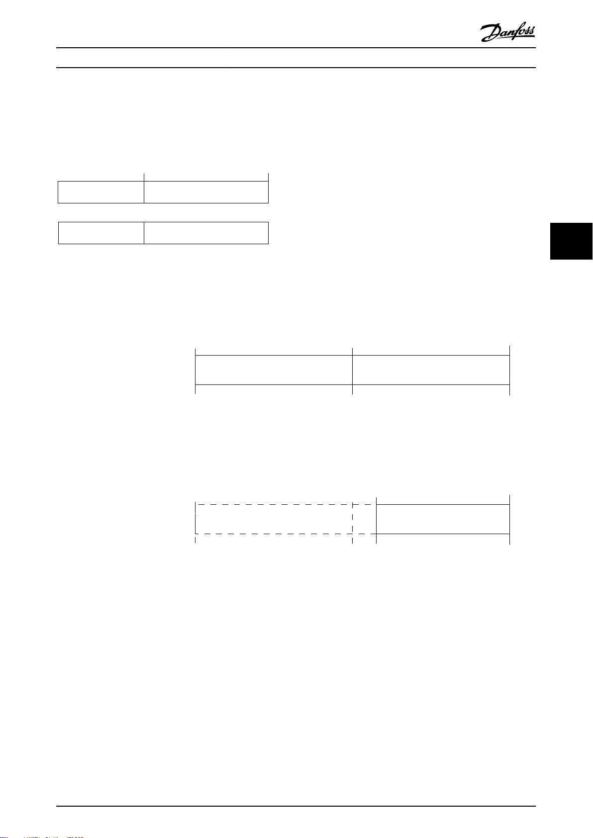
Actual output
frequency
STW
Follower-slave
Speed referenceCTW
Master-slave
16bit
130BA276.11
Reverse Forward
Par.3-00 set to
(1) -max- +max
Max reference Max reference
Par.3-00 set to
(0) min-max
Max reference
Forward
Min reference
100%
(4000hex)
-100%
(C000hex)
0%
(0hex)
Par.3-03 0 Par.3-03
Par.3-03
(4000hex)(0hex)
0% 100%
Par.3-02
130BA277.10
RS485 安装和设置 设计指南
5.11.3 总线速度参考值
以一个相对百分比值的形式将速度参考值传输给变频器。以一个 16 位字的形式传输该值。如果整数值为 16384(4000
(十六进制)),则表示 100%。负数借助 2 的补码表示。实际输出频率 (MAV) 与总线参考值的标定方式相同。
图 5.15 实际输出频率 (MAV)
参考值和 MAV 的标定方式如下:
5 5
图 5.16 参考值 和 MAV
MG06B541 Danfoss A/S © 03/2019 全权所有。 73
Page 76

130BF817.10
FC
+24 V
D IN
D IN
D IN
D IN
D IN
+10 V
A IN
A IN
COM
12
18
19
27
29
32
33
50
53
54
55
42
A OUT
D IN
D IN
31
+24 V
D IN
D IN
D IN
D IN
D IN
D IN
+10 V
A IN
A IN
COM
A OUT
12
31
18
19
27
29
32
33
50
53
54
55
42
0 ~10 V
+
-
FC
130BF818.10
D IN
130BF819.10
+24 V
D IN
D IN
D IN
D IN
D IN
D IN
+10 V
A IN
A IN
COM
A OUT
12
31
18
19
27
29
32
33
50
53
54
55
42
4 - 20mA
+
-
FC
D IN
应用示例
6 应用示例
VLT® AutomationDrive FC 360
6
6.1 简介
本节的示例旨在提供与常见应用有关的简单参考 。
除非另有说明,否则参数设置都采用相关区域
•
(在
参数 0-03 区域性设置
中选择)的默认
值。
与端子及其设置相关的参数显示在插图的旁侧
•
在需要对模拟端子 53 或 54 进行开关设置时还
•
显示。
6.1.1 AMA
参数
功能 设置
参
数 1-29 Automatic
Motor Adaptation
[1] 启用
完整 AMA
6.1.2 速度
参数
功能 设置
参数 6-10 端子
53 低电压
参数 6-11 端子
53 高电压
参数 6-14 53 端参
考/反馈低
参数 6-15 53 端参
考/反馈高
参
数 6-19 Terminal
53 mode
*=默认值
说明/备注:
*0.07 V
*10 V
*0
50 Hz
*[1] 电压
(AMA)
参
数 5-12 Terminal
27 Digital Input
*=默认值
说明/备注: 根据电机规格设
置
参数组 1-2* 电机数据
注意
如果未连接端子 12 和
27,则将
27 数字输入
功能
。
表 6.1 在连接端子 27 的情况下执行 AMA
参数 5-12 端子
设为
*[2] 惯
性停车
。
[0] 无
表 6.2 模拟速度参考值(电压)
参数
功能 设置
参数 6-22 端子
54 低电流
参数 6-23 端子
54 高电流
参数 6-24 54 端
参考/反馈低
参数 6-25 54 端
参考/反馈高
参
数 6-29 Terminal
*4 mA
*20 mA
*0
50 Hz
[0] 电流
54 mode
*=默认值
表 6.3 模拟量速度参考值(电流)
说明/备注:
74 Danfoss A/S © 03/2019 全权所有。 MG06B541
Page 77
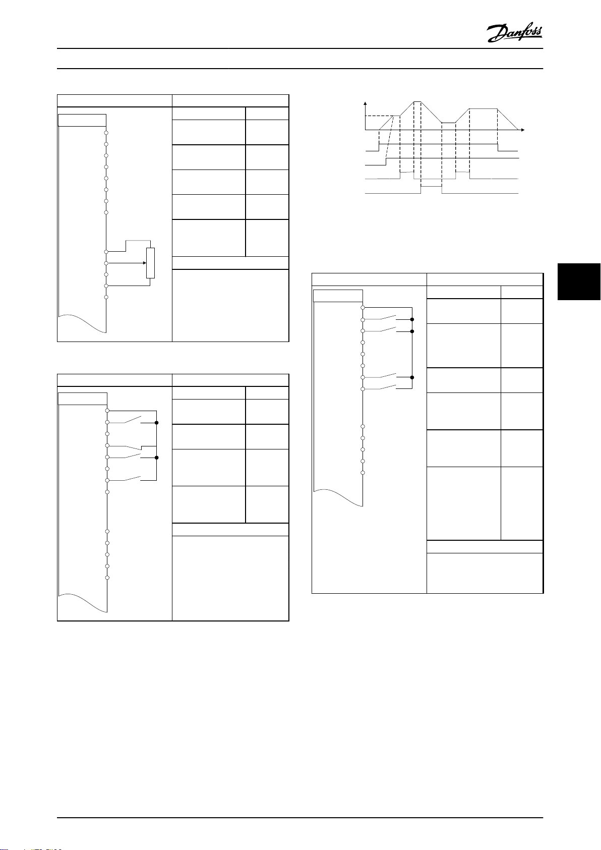
130BF820.10
+24 V
D IN
D IN
D IN
D IN
D IN
D IN
+10 V
A IN
A IN
COM
A OUT
12
31
18
19
27
29
32
33
50
53
54
55
42
≈ 5kΩ
FC
D IN
FC
+24 V
D IN
D IN
D IN
D IN
D IN
D IN
+10
V
A IN
A IN
COM
A OUT
12
31
18
19
27
29
32
33
50
53
54
55
42
130BF821.10
D IN
130BB840.12
Speed
Reference
Start (18)
Freeze ref (27)
Speed up (29)
Speed down (32)
130BF822.10
FC
+24 V
D IN
D IN
D IN
D IN
D IN
D IN
+10 V
A IN
A IN
COM
A OUT
12
19
18
27
29
32
33
50
53
54
55
42
31
D IN
应用示例 设计指南
参数
功能 设置
参数 6-10 端子
53 低电压
参数 6-11 端子
53 高电压
参数 6-14 53 端
参考/反馈低
参数 6-15 53 端
参考/反馈高
*0.07 V
*10 V
*0
50 Hz
参
数 6-19 Terminal
*[1] 电压
53 mode
*=默认值
说明/备注:
表 6.4 速度参考值(使用手动电位计)
参数
功能 设置
参数 5-10 端子
18 数字输入
参数 5-12 端子
27 数字输入
参
*[8] 启动
[19] 锁定
参考值
[21] 加速
数 5-13 Terminal
29 Digital Input
参
[22] 减速
数 5-14 Terminal
32 Digital Input
*=默认值
说明/备注:
图 6.1 加速/减速
6.1.3 启动/停止
参数
功能 设置
参数 5-10 端子
18 数字输入
参
数 5-11 Terminal
19 Digital Input
参数 5-12 端子
27 数字输入
参
数 5-14 Terminal
32 Digital Input
参
数 5-15 Terminal
33 Digital Input
参数 3-10 Preset
Reference
预置参考值 0
预置参考值 1
预置参考值 2
预置参考值 3
*=默认值
说明/备注:
*[8] 启动
*[10] 反
向
[0] 无功
能
[16] 预置
参考值位
0
[17] 预置
参考值位
1
25%
50%
75%
100%
6
6
表 6.6 带反向功能和 4 个预设速度的启动/停止
表 6.5 加速/减速
MG06B541 Danfoss A/S © 03/2019 全权所有。 75
Page 78
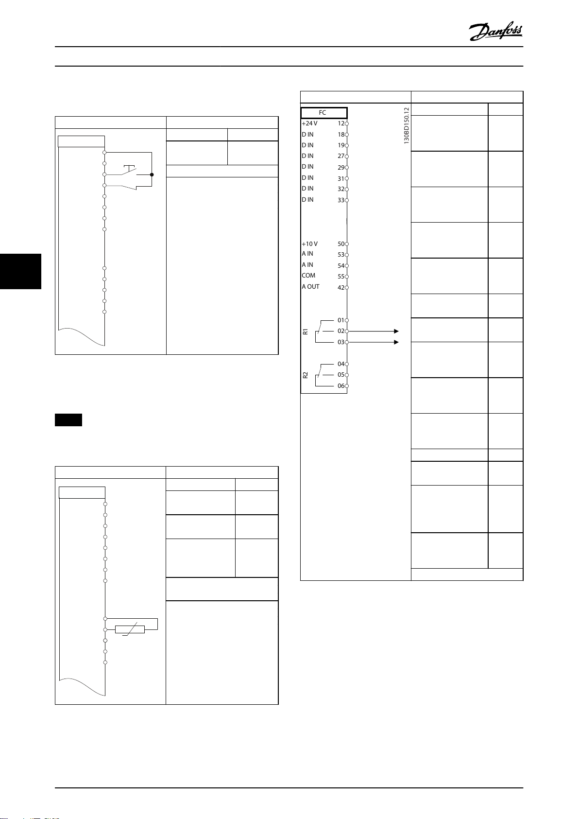
130BF823.10
FC
+24 V
D IN
D IN
D IN
D IN
D IN
D IN
+10 V
A IN
A IN
COM
A OUT
12
31
18
19
27
29
32
33
50
53
54
55
42
D IN
130BF824.10
+24 V
D IN
D IN
D IN
D IN
D IN
+10 V
A IN
A IN
COM
A OUT
12
31
18
19
27
29
32
33
50
53
54
55
42
FC
D IN
D IN
FC
+24 V
D IN
D IN
D IN
D IN
D IN
D IN
D IN
+10
V
A IN
A IN
COM
A OUT
R
1
R
2
12
18
19
27
29
32
33
315053
54
55
42
01
02
03
04
05
06
应用示例
VLT® AutomationDrive FC 360
6
6.1.4 外部报警复位
参数
功能 设置
参数 5-11 端子
19 数字输入
[1] 复位
*=默认值
说明/备注:
表 6.7 外部报警复位
6.1.5 电机热敏电阻
注意
为了符合 PELV 绝缘要求,必须在热敏电阻上使用加强绝
缘或双重绝缘。
参数
功能 设置
参数 1-90 电动机
热保护
参数 1-93 热敏电阻源[1] 模拟
参
数 6-19 Terminal
53 mode
* = 默认值
[2] 热敏
电阻跳闸
输入端 53
*[1] 电压
参数
功能 设置
参数 4-30 Motor
Feedback Loss
Function
参数 4-31 Motor
Feedback Speed
Error
参数 4-32 Motor
Feedback Loss
Timeout
参数 7-00 Speed
PID Feedback
Source
参
数 17-11 Resolutio
n (PPR)
参数 13-00 条件控
制器模式
参数 13-01 Start
Event
参数 13-02 Stop
Event
参
数 13-10 Comparato
r Operand
参
数 13-11 Comparato
r Operator
参数 13-12 比较值
参数 13-51 SL
Controller Event
参数 13-52 SL
Controller Action
参数 5-40 Function
Relay
*=默认值
[1] 警
告
100
5 s
[2] MCB
102
1024*
[1] 开
[19] 警
告
[44]
Reset(
复位)键
[21] 警
告编号
[1] ≈*
90
[22] 比
较器 0
[32] 数
字输出
A 置为
低
[80] SL
数字输
出 A
说明/备注:
如果仅需要发出警告,则将
数 1-90 电动机热保护
[1] 热敏电阻警告
设为
。
参
表 6.8 电机热敏电阻
76 Danfoss A/S © 03/2019 全权所有。 MG06B541
Page 79
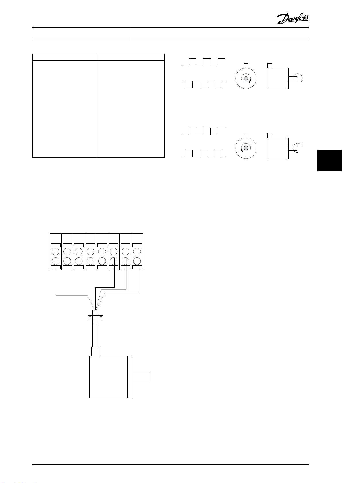
130BD366.12
+24 V DC
A
B
GND
12 18 322719 29 33 20
B
A
B
A
130BA646.10
CW
CCW
应用示例 设计指南
参数
说明/备注:
如果反馈监视器中的极限被超
表 6.9 使用 SLC 设置继电器
过,则将会发出
监视
。SLC 监视器
馈监视
。如果
视
变为“真”,则继电器 1 将
跳闸。
外部设备可以指示是否需要维
护。如果反馈错误在 5 秒钟内
再次低于相关极限,则变频器
会继续工作,而警告也将消
失。但继电器 1 仍将跳闸,直
到按了 [Off/Reset](关闭/复
位)。
警告 90 反馈
警告 90 反
警告 90 反馈监
6.1.6 编码器连接
图 6.3 24 V 增量型编码器,最大电缆长度 5 米(16.4 英
尺)
6
6
本指南旨在为设置编码器与变频器的连接提供方便。设置
编码器之前,将显示闭环速度控制系统的基本设置。
6.1.7 编码器方向
脉冲进入变频器的顺序决定了编码器的方向。
顺时针方向表示通道 A 在通道 B 前 90 电度。
逆时针方向表示通道 B 在通道 A 前 90 电度。
通过观察轴端可确定此方向。
6.1.8 闭环变频器系统
变频器系统通常由多个部分组成,比如:
电机。
•
制动器(变速箱、机械制动)。
•
变频器。
•
作为反馈系统的编码器。
•
用于动态制动的制动电阻器。
•
传动装置。
•
负载。
•
要求机械制动控制的应用环境通常需要制动电阻器。
图 6.2 24 V 或 10 - 30 V 编码器
MG06B541 Danfoss A/S © 03/2019 全权所有。 77
Page 80

Motor
Gearbox
Load
Transmission
Encoder Mech. brake
Brake resistor
130BA120.10
6
应用示例
VLT® AutomationDrive FC 360
图 6.4 闭环速度控制的基本设置
78 Danfoss A/S © 03/2019 全权所有。 MG06B541
Page 81

索引 设计指南
索引
A
AMA.............................................. 7
C
CE 标志.......................................... 9
E
EMC............................................. 50
EMC 抗扰性要求.................................. 34
EMC 指令......................................... 9
EMC 测试结果.................................... 34
EMC 辐射简介.................................... 33
EMC 防范措施.................................... 59
ETR.......................................... 7, 40
另请参阅
电子热敏继电器
F
FC 协议
FC 协议....................................... 70
协议概述...................................... 59
带 Modbus RTU 的 FC........................... 59
I
IEC 61800-3................................. 13, 50
IND............................................. 62
L
LCP....................................... 6, 7, 19
LCP 控制键...................................... 19
M
Modbus RTU...................................... 63
Modbus RTU 命令................................. 67
Modbus RTU 概述................................. 63
Modbus 异常代码................................. 66
Modbus 通讯..................................... 59
P
PELV........................................ 49, 76
PELV , 保护性超低压............................ 35
R
RCD.............................................. 7
RFI 滤波器...................................... 13
RS485
RS485..................................... 58, 59
安装和设置.................................... 58
V
VVC+......................................... 8, 18
VVC+ 模式下的静态过载........................... 40
与
与使用主电源.................................... 51
中
中间电路.................................... 40, 52
串
串行通讯..................................... 6, 15
主
主电源
(L1, L2, L3).................................. 47
主电源数据.................................... 45
主电源断电.................................... 40
主电源电压..................................... 7
低
低电压指令....................................... 9
供
供电电压........................................ 49
保
保护............................................ 35
保护与功能...................................... 50
保持输出频率.................................... 70
内
内部电流控制, VVC+ 模式......................... 19
制
制动
制动功率....................................... 7
制动电阻器..................................... 7
制动功率........................................ 38
制动功能........................................ 38
制动电阻器.................................. 37, 43
功
功率因数........................................ 13
功能代码........................................ 66
MG06B541 Danfoss A/S © 03/2019 全权所有。 79
Page 82

索引
VLT® AutomationDrive FC 360
升
升速/减速....................................... 21
升高时间........................................ 52
参
参数号 (PNU).................................... 61
参考值极限...................................... 21
同
同步电机速度..................................... 6
噪
噪声隔离........................................ 13
在
在连接端子 27 的情况下执行 AMA.................. 74
地
地线............................................ 13
声
声源性噪音...................................... 52
处
处理说明......................................... 9
复
复位............................................ 50
复位报警........................................ 19
多
多台变频器...................................... 13
安
安全注意事项..................................... 8
寄
寄存器.......................................... 67
屏
屏蔽控制电缆.................................... 15
屏蔽电缆........................................ 13
开
开环............................................ 50
总
总线参考值...................................... 22
惯
惯性停车................................. 6, 70, 72
感
感生电压........................................ 13
报
报文长度 (LGE).................................. 60
指
指令, EMC........................................ 9
指令, 低电压..................................... 9
指令, 机械....................................... 9
接
接地........................................ 13, 14
接地三角形连接电源.............................. 13
接地回路........................................ 16
控
控制
控制字........................................ 70
控制线路...................................... 13
特性.......................................... 50
控制卡
+10 V 直流输出................................ 49
RS485 串行通讯................................ 49
性能.......................................... 50
控制电缆........................................ 16
控制线路........................................ 13
控制结构
开环.......................................... 19
支
支路保护........................................ 51
放
放电时间......................................... 9
数
数字输出........................................ 49
数据类型, 支持的................................ 62
机
机械夹持制动.................................... 37
80 Danfoss A/S © 03/2019 全权所有。 MG06B541
Page 83

索引 设计指南
机械指令......................................... 9
极
极端运行条件.................................... 40
模
模拟参考值...................................... 22
模拟反馈........................................ 22
模拟输出........................................ 49
横
横截面积........................................ 47
死
死区............................................ 23
浮
浮动三角形连接电源.............................. 13
滑
滑差补偿......................................... 8
电
电压水平........................................ 47
电子热敏继电器................................... 7
另请参阅
电机
热保护........................................ 72
电动机产生过电压.............................. 40
电机保护...................................... 50
电机热保护.................................... 40
电机电缆...................................... 13
电机相位...................................... 40
电机线路...................................... 13
电机输出...................................... 47
电机功率........................................ 13
电机电压........................................ 52
电机自动整定..................................... 7
电机额定电流..................................... 6
电机额定速度..................................... 6
电气噪声........................................ 13
电源循环......................................... 7
电源连接........................................ 13
电缆长度........................................ 47
ETR
漏
漏电电流........................................ 36
点
点动......................................... 6, 71
热
热敏电阻..................................... 8, 76
熔
熔断器.......................................... 51
特
特殊条件........................................ 53
状
状态字.......................................... 71
独
独立主电源...................................... 13
环
环境条件........................................ 50
直
直流制动........................................ 70
短
短路............................................ 40
硬
硬件设置........................................ 59
端
端子设置........................................ 15
索
索引 (IND)...................................... 62
线
线圈............................................ 67
线缆规格........................................ 13
继
继电器输出...................................... 49
缩
缩略语........................................ 0
MG06B541 Danfoss A/S © 03/2019 全权所有。 81
Page 84

索引
VLT® AutomationDrive FC 360
网
网络 连接....................................... 58
网络配置........................................ 64
能
能效........................................ 45, 46
能效等级........................................ 50
脉
脉冲参考值................................... 6, 22
脉冲反馈........................................ 22
读
读取保持寄存器(03 [十六进制])................. 69
读取线圈........................................ 67
起
起步转矩......................................... 6
跳
跳闸............................................. 8
选
选配设备........................................ 14
速
速度 PID.................................... 16, 18
速度 PID 控制................................... 26
速度参考值...................................... 74
锁
锁定参考值...................................... 21
锁定输出......................................... 6
间
间歇工作周期..................................... 7
降
降容............................................ 50
预
预置参考值...................................... 22
转
转动惯量........................................ 40
转矩
转矩特性...................................... 47
转矩控制........................................ 16
输
输入
数字输入.................................. 19, 47
模拟输入...................................... 48
模拟输出.................................... 6, 7
脉冲输入...................................... 48
输入电源...................................... 13
输入信号........................................ 15
输入电源........................................ 13
输出
模拟输出....................................... 7
输出电流........................................ 49
过
过程 PID 控制................................... 28
进
进行输出切换.................................... 40
82 Danfoss A/S © 03/2019 全权所有。 MG06B541
Page 85

索引 设计指南
MG06B541 Danfoss A/S © 03/2019 全权所有。 83
Page 86

丹佛斯(上海)自动控制
有限公司广州办事处
广州市珠江新城花城大道87号
高德置地广场B塔704室
电话:020-28348000
传真:020-28348001
邮编:510623
丹佛斯(上海)自动控制
有限公司北京办事处
北京市朝阳区工体北路
甲2号盈科中心A栋20层
电话:010-85352588
传真:010-85352599
邮编:100027
丹佛斯(上海)自动
控制有限公司
上海市宜山路900号
科技大楼C楼20层
电话:021-61513000
传真:021-61513100
邮编:200233
丹佛斯(上海)自动控制
有限公司成都办事处
成都市下南大街2号宏达
国际广场11层1103-1104室
电话:028-87774346,43
传真:028-87774347
邮编:610016
丹佛斯(上海)自动控制
有限公司青岛办事处
青岛市山东路40号
广发金融大厦1102A室
电话:0532-85018100
传真:0532-85018160
邮编:266071
丹佛斯(上海)自动控制
有限公司西安办事处
西安市二环南路88号
老三届世纪星大厦25层C座
电话:029-88360550
传真:029-88360551
邮编:710065
Danfoss 对其目录、手册以及其它印刷资料可能出现的错误不负任何责任。Danfoss 保留未预先通知而更改产品的权利。该限制并适用于已订购但更改并不会过多改变已同意规格的货物。
本材料所引用的商标均为相应公司之财产。Danfoss 及 Danfoss 的标记均为 Danfoss A/S 之注册商标。全权所有。
Danfoss A/S
Ulsnaes 1
DK-6300 Graasten
vlt-drives.danfoss.com
130R0499 MG06B541 03/2019
*MG06B541*
 Loading...