

Page 1
Installation Instructions
Mains, Motor and DC Link Terminals
®
VLT
AutomationDrive FC 360
The instructions provide information about the replacement of
the mains terminals, motor terminals, and DC link terminals in
®
the VLT
Only Danfoss-authorised, qualified personnel is allowed to
repair this equipment. The personnel must be familiar with the
instructions and safety measures described in the
VLT
AutomationDrive FC 360.
®
AutomationDrive FC 360 Service Manual.
Items Supplied
Items supplied depend on ordered code number and
enclosure type of the frequency converter.
Code number Items supplied
132b0297
132b0298
132b0299
132b0315
132b0316
132b0317
Mains terminal, enclosure type J6
•
Motor terminal, enclosure type J6
•
DC link terminal, enclosure type J6
•
Mains and motor terminal, enclosure type J7,
•
55 kW (3-phase block)
DC link terminal, enclosure type J7, 55 kW (2-
•
phase block)
Terminal for DC link, mains or motor,
•
enclosure type J7, 75 kW (1 single-phase
block supplied per order)
Safety Instructions
WARNING
DISCHARGE TIME
The frequency converter contains DC-link capacitors, which
can remain charged even when the frequency converter is
not powered. Failure to wait the specified time after power
has been removed before performing service or repair work,
could result in death or serious injury.
1. Stop the motor.
2. Disconnect AC mains, permanent magnet type
motors, and remote DC-link power supplies,
including battery back-ups, UPS, and DC-link
connections to other frequency converters.
3. Wait for the capacitors to discharge fully, before
performing any service or repair work. The duration
of waiting time is specified in Table 1.1.
Minimum waiting time (minutes)
Voltage [V]
415
380-480 0.37-7.5 kW 11-75 kW
High voltage may be present even when the warning LEDs are off!
Table 1.1 Discharge Time
Tools Required
Screwdrivers:
•
-
-
-
-
-
N8 socket wrench
•
N10 socket wrench
•
N5 Allen key
•
Flat-edged
T10
T20
T25
T30
Danfoss A/S © Rev. 2014-01-17 All rights reserved. MI06P102
Page 2
Installation Instructions
Mains, Motor and DC Link Terminals
®
VLT
AutomationDrive FC 360
Installation
Replacing motor and DC link terminals for enclosure type
J6
1. Follow the instructions in
2. Unscrew the 3 M4x18 (T20) screws holding the
3. Unscrew the 2 M4x12 (T20) screws holding the DC
4. Install new motor or DC link terminals in reverse
®
AutomationDrive FC 360 Service Manual to
VLT
remove the power control card.
busbar to motor terminals, and remove the motor
terminals.
link terminal and remove the DC link terminal.
order.
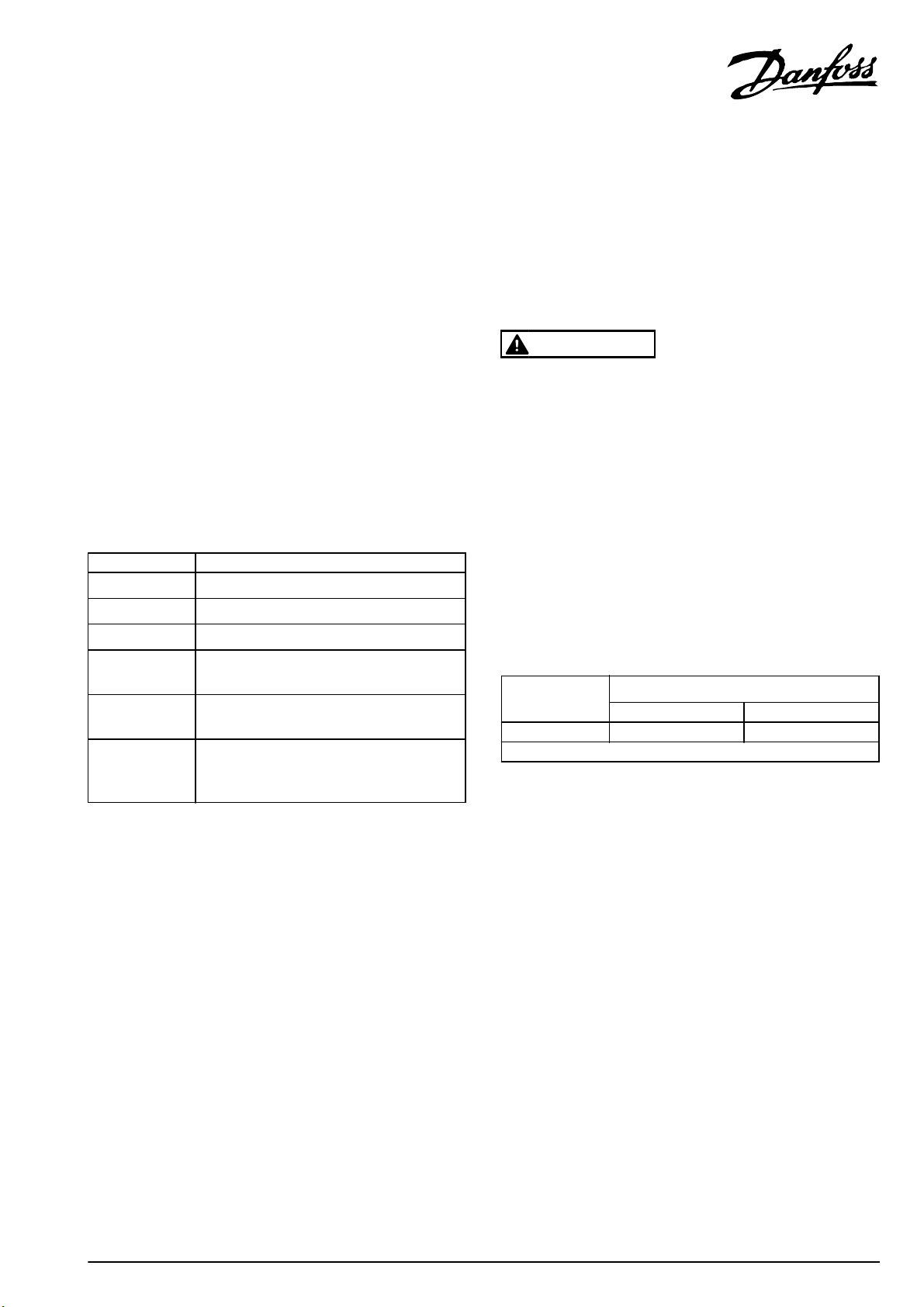
1 Screws (T20, M4x18), holding the busbar to motor
terminal
2 Screws (T20, M4x12), holding the DC link terminal
Illustration 1.1 Motor Terminals and DC Link Terminals for J6
Replacing mains terminals for enclosure type J6
1. Follow the instructions in FC 360 Service Manual to
remove the power control card.
2. Follow the instructions in FC 360 Service Manual (see
the chapter on power card replacement) to remove:
RFI auxiliary card
•
Mains terminal (L1, L2, L3) screws (3xM4) on
•
rectifier module
Mains input cover
•
Mains input screen and cable
•
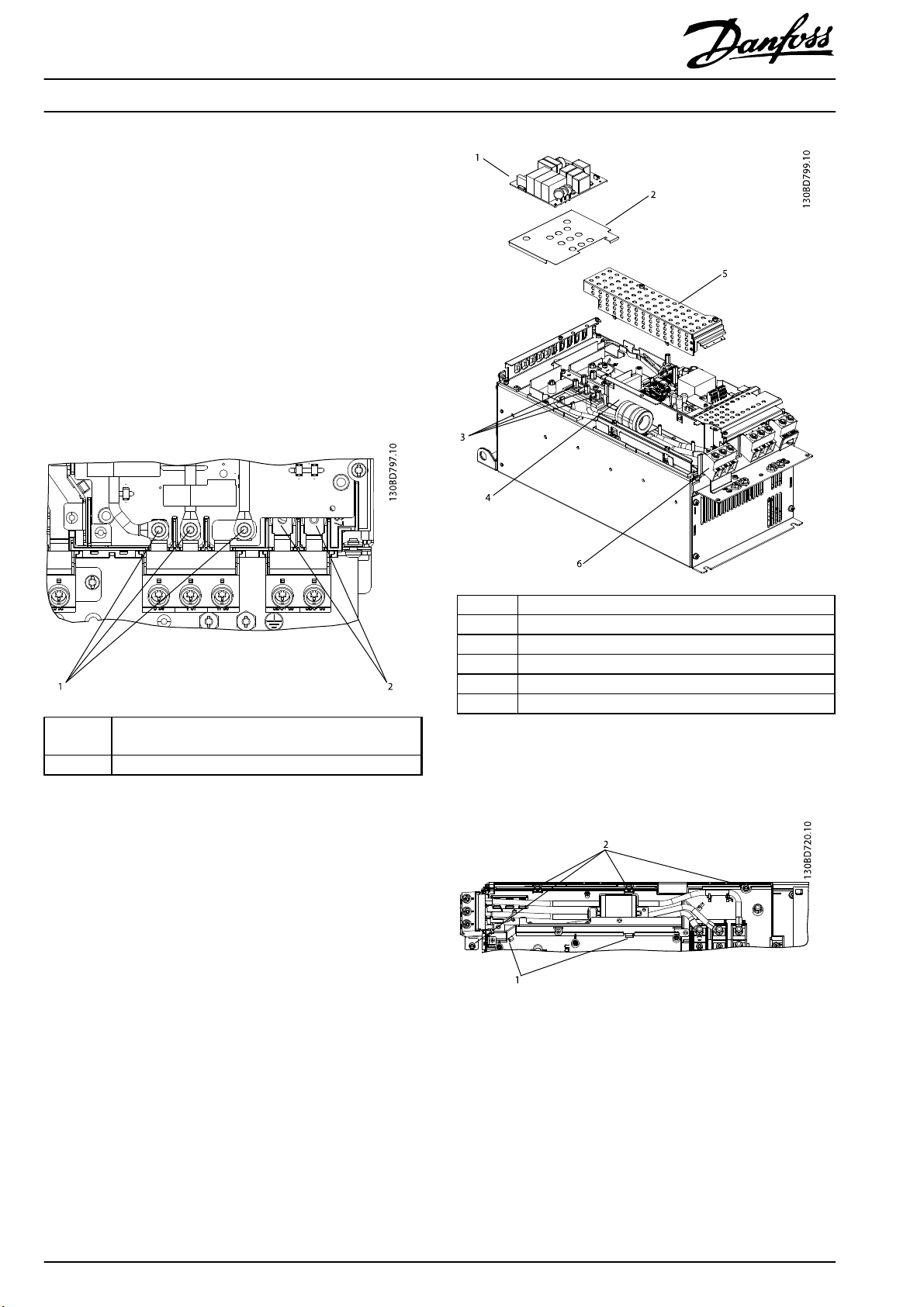
1RFI auxiliary card
2 Insulation foil
3 Mains terminal screws on rectifier module
4 Mains input screen and cable
5Mains input cover
6 Mains terminals
Illustration 1.2 Mains Terminals and Related Components for J6
3. Remove mains terminals and cables.
Illustration 1.3 Mains Terminals and Cables
4. Install new mains terminals in reverse order.
2
Danfoss A/S © Rev. 2014-01-17 All rights reserved. MI06P102
Page 3

Installation Instructions
Replacing mains terminals, motor terminals, and DC link
terminals for enclosure type J7
Mains, Motor and DC Link Terminals
®
VLT
AutomationDrive FC 360
NOTICE
55 kW terminals are supplied in 3-phase and 2-
•
phase blocks.
75 kW terminals are supplied in single-phase
•
blocks.
1. Follow the instructions in FC 360 Service Manual to
remove the power control card of the frequency
converter.
2. Follow the instructions in FC 360 Service Manual (see
chapter on power card replacement) to remove the
following components:
EMC screen plate
•
RFI filter assembly (only needed when
•
replacing a mains terminal).
1 RFI filter assembly
2 EMC screen plate
3 Motor terminals
4DC link terminals
5 Mains terminals
Illustration 1.4 J7 Terminal Overview
3. Unscrew the 2 M5x10 screws (T20) on the defective
terminal, and remove the terminal.
4. Install the new terminal in reverse order.
MI06P102 Danfoss A/S © Rev. 2014-01-17 All rights reserved.
3
Page 4

MI06P102132R0219 Rev. 2014-01-17
*MI06P102*
 Loading...