

Page 1
ENGINEERING TOMORROW
Design Guide
VLT® AutomationDrive FC 302
315–1200 kW
vlt-drives.danfoss.com
Page 2

Page 3

Contents Design Guide
Contents
1 Introduction
1.1 Purpose of the Design Guide
1.2 Additional Resources
1.3 Document and Software Version
1.4 Conventions
2 Safety
2.1 Safety Symbols
2.2 Qualied Personnel
2.3 Safety Precautions
3 Approvals and Certications
3.1 Regulatory/Compliance Approvals
3.2 Enclosure Protection Ratings
4 Product Overview
4.1 VLT® High-power Drives
4.2 Enclosure Size by Power Rating
5
5
5
5
5
6
6
6
6
8
8
10
12
12
12
4.3 Overview of Enclosures, 380–500 V
4.4 Overview of Enclosures, 525–690 V
4.5 Kit Availability
5 Product Features
5.1 Automated Operational Features
5.2 Custom Application Features
5.3 Dynamic Braking Overview
5.4 Mechanical Holding Brake Overview
5.5 Load Share Overview
5.6 Regen Overview
6 Options and Accessories Overview
6.1 Fieldbus Devices
6.2 Functional Extensions
6.3 Motion Control and Relay Cards
6.4 Brake Resistors
6.5 Sine-wave Filters
13
16
19
20
20
22
26
27
30
31
32
32
33
35
35
36
6.6 dU/dt Filters
6.7 Common-mode Filters
6.8 Harmonic Filters
6.9 Enclosure Built-in Options
6.10 High-power Kits
MG34S302 Danfoss A/S © 11/2017 All rights reserved. 1
36
36
36
36
38
Page 4

Contents
VLT® AutomationDrive FC 302
315–1200 kW
7 Specications
7.1 Electrical Data, 380–500 V
7.2 Electrical Data, 525–690 V
7.3 Mains Supply
7.4 Motor Output and Motor Data
7.5 Ambient Conditions
7.6 Cable Specications
7.7 Control Input/Output and Control Data
7.8 Enclosure Weights
7.9 Airow for Enclosures E1–E2 and F1–F13
8 Exterior and Terminal Dimensions
8.1 E1 Exterior and Terminal Dimensions
8.2 E2 Exterior and Terminal Dimensions
8.3 F1 Exterior and Terminal Dimensions
8.4 F2 Exterior and Terminal Dimensions
8.5 F3 Exterior and Terminal Dimensions
8.6 F4 Exterior and Terminal Dimensions
39
39
45
51
51
51
52
52
55
56
58
58
66
74
81
88
100
8.7 F8 Exterior and Terminal Dimensions
8.8 F9 Exterior and Terminal Dimensions
8.9 F10 Exterior and Terminal Dimensions
8.10 F11 Exterior and Terminal Dimensions
8.11 F12 Exterior and Terminal Dimensions
8.12 F13 Exterior and Terminal Dimensions
9 Mechanical Installation Considerations
9.1 Storage
9.2 Lifting the Unit
9.3 Operating Environment
9.4 Mounting Congurations
9.5 Cooling
9.6 Derating
10 Electrical Installation Considerations
10.1 Safety Instructions
10.2 Wiring Schematic
111
115
121
127
135
141
149
149
149
150
151
152
153
156
156
157
10.3 Connections
10.4 Control Wiring and Terminals
10.5 Fuses and Circuit Breakers
10.6 Disconnects and Contactors
10.7 Motor
2 Danfoss A/S © 11/2017 All rights reserved. MG34S302
158
162
169
173
174
Page 5

Contents Design Guide
10.8 Braking
10.9 Residual Current Devices (RCD) and Insulation Resistance Monitor (IRM)
10.10 Leakage Current
10.11 IT Grid
10.12 Eciency
10.13 Acoustic Noise
10.14 dU/dt Conditions
10.15 Electromagnetic Compatibility (EMC) Overview
10.16 EMC-compliant Installation
10.17 Harmonics Overview
11 Basic Operating Principles of a Drive
11.1 Description of Operation
11.2 Drive Controls
12 Application Examples
12.1 Programming a Closed-loop Drive System
12.2 Wiring Congurations for Automatic Motor Adaptation (AMA)
177
179
179
180
180
181
181
182
186
189
192
192
192
201
201
201
12.3 Wiring Congurations for Analog Speed Reference
12.4 Wiring Congurations for Start/Stop
12.5 Wiring Conguration for an External Alarm Reset
12.6 Wiring Conguration for Speed Reference Using a Manual Potentiometer
12.7 Wiring Conguration for Speed Up/Speed Down
12.8 Wiring Conguration for RS485 Network Connection
12.9 Wiring Conguration for a Motor Thermistor
12.10 Wiring Conguration for a Relay Set-up with Smart Logic Control
12.11 Wiring Conguration for Mechanical Brake Control
12.12 Wiring Conguration for the Encoder
12.13 Wiring Conguration for Torque and Stop Limit
13 How to Order a Drive
13.1 Drive Congurator
13.2 Ordering Numbers for Options/Kits
13.3 Ordering Numbers for Filters and Brake Resistors
13.4 Spare Parts
202
202
204
204
204
205
205
206
206
207
208
209
209
213
216
216
14 Appendix
14.1 Abbreviations and Symbols
14.2 Denitions
14.3 RS485 Installation and Set-up
14.4 RS485: FC Protocol Overview
14.5 RS485: FC Protocol Telegram Structure
MG34S302 Danfoss A/S © 11/2017 All rights reserved. 3
217
217
218
219
220
220
Page 6

Contents
VLT® AutomationDrive FC 302
315–1200 kW
14.6 RS485: FC Protocol Parameter Examples
14.7 RS485: Modbus RTU Overview
14.8 RS485: Modbus RTU Telegram Structure
14.9 RS485: Modbus RTU Message Function Codes
14.10 RS485: Modbus RTU Parameters
14.11 RS485: FC Control Prole
Index
225
225
226
229
229
230
237
4 Danfoss A/S © 11/2017 All rights reserved. MG34S302
Page 7
Introduction Design Guide
1 Introduction
1.1 Purpose of the Design Guide
This design guide is intended for:
Project and systems engineers.
•
Design consultants.
•
Application and product specialists.
•
The design guide provides technical information to
understand the capabilities of the drive for integration into
motor control and monitoring systems.
VLT® is a registered trademark.
1.2 Additional Resources
Other resources are available to understand advanced
drive operation, programming, and directives compliance.
The operating guide provides detailed information
•
for the installation and start-up of the drive.
The programming guide provides greater detail on
•
how to work with parameters and includes many
application examples.
®
The VLT
•
describes how to use Danfoss drives in functional
safety applications. This manual is supplied with
the drive when the Safe Torque O option is
present.
The VLT® Brake Resistor MCE 101 Design Guide
•
describes how to select the optimal brake resistor.
Safe Torque O Operating Guide
Document and Software Version
1.3
This manual is regularly reviewed and updated. All
suggestions for improvement are welcome. Table 1.1 shows
the document version and the corresponding software
version.
Edition Remarks Software
version
MG34S3xx Removed D1h–D8h content and
implemented new structure.
Table 1.1 Document and Software Version
8.03
1.4 Conventions
Numbered lists indicate procedures.
•
Bullet lists indicate other information and
•
description of illustrations.
Italicized text indicates:
•
- Cross-reference.
- Link.
- Footnote.
- Parameter name, parameter group
name, parameter option.
All dimensions in drawings are in mm (in).
•
An asterisk (*) indicates a default setting of a
•
parameter.
1 1
The VLT® Advanced Harmonic Filters AHF 005/AHF
•
010 Design Guide describes harmonics, various
mitigation methods, and the operating principle
of the advanced harmonics lter. This guide also
describes how to select the correct advanced
harmonics lter for a particular application.
The Output Filters Design Guide explains why it is
•
necessary to use output lters for certain
applications, and how to select the optimal dU/dt
or sine-wave lter.
Optional equipment is available that can change
•
some of the information described in these
publications. For specic requirements, see the
instructions supplied with the options.
Supplementary publications and manuals are available
from Danfoss. See drives.danfoss.com/downloads/portal/#/
for listings.
MG34S302 Danfoss A/S © 11/2017 All rights reserved. 5
Page 8
Safety
VLT® AutomationDrive FC 302
315–1200 kW
2 Safety
22
2.1 Safety Symbols
The following symbols are used in this guide:
WARNING
Indicates a potentially hazardous situation that could
result in death or serious injury.
CAUTION
Indicates a potentially hazardous situation that could
result in minor or moderate injury. It can also be used to
alert against unsafe practices.
NOTICE
Indicates important information, including situations that
can result in damage to equipment or property.
2.2 Qualied Personnel
Only qualied personnel are allowed to install or operate
this equipment.
WARNING
DISCHARGE TIME
The drive contains DC-link capacitors, which can remain
charged even when the drive is not powered. High
voltage can be present even when the warning LED
indicator lights are o. Failure to wait 40 minutes after
power has been removed before performing service or
repair work can result in death or serious injury.
1. Stop the motor.
2. Disconnect AC mains and remote DC-link
supplies, including battery back-ups, UPS, and
DC-link connections to other drives.
3. Disconnect or lock motor.
4. Wait 40 minutes for the capacitors to discharge
fully.
5. Before performing any service or repair work,
use an appropriate voltage measuring device to
make sure that the capacitors are fully
discharged.
Qualied personnel are dened as trained sta, who are
authorized to install, commission, and maintain equipment,
systems, and circuits in accordance with pertinent laws and
regulations. Also, the personnel must be familiar with the
instructions and safety measures described in this manual.
Safety Precautions
2.3
WARNING
HIGH VOLTAGE
Drives contain high voltage when connected to AC mains
input, DC supply, load sharing, or permanent motors.
Failure to use qualied personnel to install, start up, and
maintain the drive can result in death or serious injury.
Only qualied personnel must install, start up,
•
and maintain the drive.
WARNING
LEAKAGE CURRENT HAZARD
Leakage currents exceed 3.5 mA. Failure to ground the
drive properly can result in death or serious injury.
Ensure the correct grounding of the equipment
•
by a certied electrical installer.
WARNING
FIRE HAZARD
Brake resistors get hot during and after braking. Failure
to place the brake resistor in a secure area can result in
property damage and/or serious injury.
Ensure that the brake resistor is placed in a
•
secure environment to avoid re risk.
Do not touch the brake resistor during or after
•
braking to avoid serious burns.
NOTICE
MAINS SHIELD SAFETY OPTION
A mains shield option is available for enclosures with a
protection rating of IP21/IP54 (Type 1/Type 12). The
mains shield is a cover installed inside the enclosure to
protect against the accidental touch of the power
terminals, according to BGV A2, VBG 4.
2.3.1 ADN-compliant Installation
To prevent spark formation in accordance with the
European Agreement concerning International Carriage of
Dangerous Goods by Inland Waterways (ADN), take
precautions for drives with protection rating of IP00
(Chassis), IP20 (Chassis), IP21 (Type 1), or IP54 (Type 12).
6 Danfoss A/S © 11/2017 All rights reserved. MG34S302
Page 9
1
2
e30bd832.10
Safety Design Guide
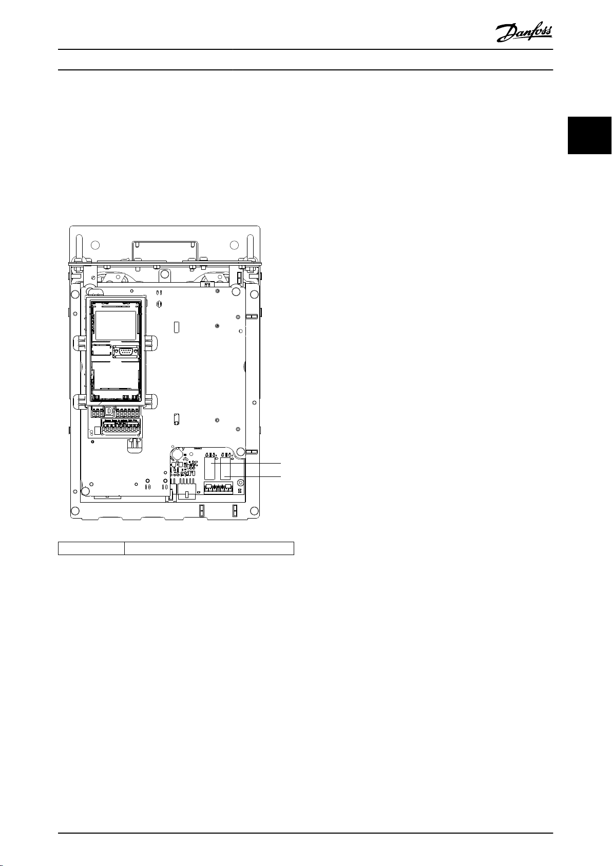
Do not install a mains switch.
•
Ensure that parameter 14-50 RFI Filter is set to
•
[1] On.
Remove all relay plugs marked RELAY. See
•
Illustration 2.1.
Check which relay options are installed, if any.
•
The only allowed relay option is VLT® Extended
Relay Card MCB 113.
2 2
1, 2 Relay plugs
Illustration 2.1 Location of Relay Plugs
MG34S302 Danfoss A/S © 11/2017 All rights reserved. 7
Page 10
Approvals and
Certication...
VLT® AutomationDrive FC 302
315–1200 kW
3 Approvals and Certications
This section provides a brief description of the various
approvals and certications that are found on Danfoss
33
drives. Not all approvals are found on all drives.
3.1 Regulatory/Compliance Approvals
NOTICE
IMPOSED LIMITATIONS ON THE OUTPUT
FREQUENCY
From software version 6.72 onwards, the output
frequency of the drive is limited to 590 Hz due to export
control regulations. Software versions 6.xx also limit the
maximum output frequency to 590 Hz, but these
versions cannot be ashed, that is, neither downgraded
nor upgraded.
3.1.1.1 CE Mark
The CE mark (Communauté Européenne) indicates that the
product manufacturer conforms to all applicable EU
directives. The EU directives applicable to the design and
manufacture of drives are listed in Table 3.1.
NOTICE
The CE mark does not regulate the quality of the
product. Technical specications cannot be deduced from
the CE mark.
EU Directive Version
Low Voltage Directive 2014/35/EU
EMC Directive 2014/30/EU
Machinery Directive
ErP Directive 2009/125/EC
ATEX Directive 2014/34/EU
RoHS Directive 2002/95/EC
Table 3.1 EU Directives Applicable to Drives
1) Machinery Directive conformance is only required for drives with
an integrated safety function.
1)
2014/32/EU
The aim of the directive is to ensure personal safety and
avoid property damage when operating electrical
equipment that is installed, maintained, and used as
intended.
EMC Directive
The purpose of the EMC (electromagnetic compatibility)
Directive is to reduce electromagnetic interference and
enhance immunity of electrical equipment and installations. The basic protection requirement of the EMC
Directive is that devices that generate electromagnetic
interference (EMI), or whose operation can be aected by
EMI, must be designed to limit the generation of electromagnetic interference. The devices must have a suitable
degree of immunity to EMI when properly installed,
maintained, and used as intended.
Electrical equipment devices used alone or as part of a
system must bear the CE mark. Systems do not require the
CE mark, but must comply with the basic protection
requirements of the EMC Directive.
Machinery Directive
The aim of the Machinery Directive is to ensure personal
safety and avoid property damage to mechanical
equipment used in its intended application. The Machinery
Directive applies to a machine consisting of an aggregate
of interconnected components or devices of which at least
1 is capable of mechanical movement.
Drives with an integrated safety function must comply with
the Machinery Directive. Drives without a safety function
do not fall under the Machinery Directive. If a drive is
integrated into a machinery system, Danfoss can provide
information on safety aspects relating to the drive.
When drives are used in machines with at least 1 moving
part, the machine manufacturer must provide a declaration
stating compliance with all relevant statutes and safety
measures.
3.1.1.2 ErP Directive
NOTICE
Drives with an integrated safety function, such as Safe
Torque O (STO), must comply with the Machinery
Directive.
Declarations of conformity are available on request.
Low Voltage Directive
Drives must be CE-labeled in accordance with the Low
Voltage Directive of January 1, 2014. The Low Voltage
Directive applies to all electrical equipment in the 50–
1000 V AC and the 75–1500 V DC voltage ranges.
8 Danfoss A/S © 11/2017 All rights reserved. MG34S302
The ErP Directive is the European Ecodesign Directive for
energy-related products, including drives. The aim of the
directive is to increase energy eciency and the level of
protection of the environment, while increasing the
security of the energy supply. Environmental impact of
energy-related products includes energy consumption
throughout the entire product life cycle.
Page 11

Approvals and Certication... Design Guide
3.1.1.3 UL Listing
The Underwriters Laboratory (UL) mark certies the safety
of products and their environmental claims based on
standardized testing. Drives of voltage T7 (525–690 V) are
UL-certied for only 525–600 V.
3.1.1.4 CSA/cUL
The CSA/cUL approval is for AC drives of voltage rated at
600 V or lower. The standard ensures that, when the drive
is installed according to the provided operating/installation
guide, the equipment meets the UL standards for electrical
and thermal safety. This mark certies that the product
performs to all required engineering specications and
testing. A certicate of compliance is provided on request.
3.1.1.5 EAC
The EurAsian Conformity (EAC) mark indicates that the
product conforms to all requirements and technical
regulations applicable to the product per the EurAsian
Customs Union, which is composed of the member states
of the EurAsian Economic Union.
The EAC logo must be both on the product label and on
the packaging label. All products used within the EAC area,
must be bought at Danfoss inside the EAC area.
3.1.1.9 Marine
In order for ships and oil/gas platforms to receive a
regulatory license and insurance, 1 or more marine certi-
cation societies must certify these applications. Up to 12
dierent marine classication societies have certied
Danfoss drive series.
To view or print marine approvals and certicates, go to
the download area at drives.danfoss.com/industries/marine-
and-oshore/marine-type-approvals/#/.
3.1.2 Export Control Regulations
Drives can be subject to regional and/or national export
control regulations.
An ECCN number is used to classify all drives that are
subject to export control regulations. The ECCN number is
provided in the documents accompanying the drive.
In case of re-export, it is the responsibility of the exporter
to ensure compliance with the relevant export control
regulations.
3 3
3.1.1.6 UKrSEPRO
UKrSEPRO certicate ensures quality and safety of both
products and services, in addition to manufacturing
stability according to Ukrainian regulatory standards. The
UkrSepro certicate is a required document to clear
customs for any products coming into and out of the
territory of Ukraine.
3.1.1.7 TÜV
TÜV SÜD is a European safety organization which certies
the functional safety of the drive in accordance to EN/IEC
61800-5-2. The TÜV SÜD both tests products and monitors
their production to ensure that companies stay compliant
with their regulations.
3.1.1.8 RCM
The Regulatory Compliance Mark (RCM) indicates
compliance with telecommunications and EMC/radiocommunications equipment per the Australian
Communications and Media Authorities EMC labeling
notice. RCM is now a single compliance mark covering
both the A-Tick and the C-Tick compliance marks. RCM
compliance is required for placing electrical and electronic
devices on the market in Australia and New Zealand.
MG34S302 Danfoss A/S © 11/2017 All rights reserved. 9
Page 12
Approvals and Certication...
VLT® AutomationDrive FC 302
315–1200 kW
3.2 Enclosure Protection Ratings
The VLT® drive series are available in various enclosure protection to accommodate the needs of the application. Enclosure
protection ratings are provided based on 2 international standards:
UL type validates that the enclosures meet NEMA (National Electrical Manufacturers Association) standards. The
•
construction and testing requirements for enclosures are provided in NEMA Standards Publication 250-2003 and UL
33
Standard Danfoss VLT® drive series are available in various enclosure protections to meet the requirements of IP00 (Chassis),
IP20 (Protected chassis) or IP21 (UL Type 1), or IP54 (UL Type 12). In this manual, UL Type is written as Type. For example,
IP21/Type 1.
UL type standard
Type 1 – Enclosures constructed for indoor use to provide a degree of protection to personnel against incidental contact
with the enclosed units and to provide a degree of protection against falling dirt.
Type 12 – General-purpose enclosures are intended for use indoors to protect the enclosed units against the following:
50, Eleventh Edition.
IP (Ingress Protection) ratings outlined by IEC (International Electrotechnical Commission) in the rest of the world.
•
Fibers
•
Lint
•
Dust and dirt
•
Light splashing
•
Seepage
•
Dripping and external condensation of noncorrosive liquids
•
There can be no holes through the enclosure and no conduit knockouts or conduit openings, except when used with oilresistant gaskets to mount oil-tight or dust-tight mechanisms. Doors are also provided with oil-resistant gaskets. In addition,
enclosures for combination controllers have hinged doors, which swing horizontally and require a tool to open.
IP standard
Table 3.2 provides a cross-reference between the 2 standards. Table 3.3 demonstrates how to read the IP number and then
denes the levels of protection. The drives meet the requirements of both.
NEMA and UL IP
Chassis IP00
Protected chassis IP20
Type 1 IP21
Type 12 IP54
Table 3.2 NEMA and IP Number Cross-reference
10 Danfoss A/S © 11/2017 All rights reserved. MG34S302
Page 13
Approvals and Certication... Design Guide
1st digit 2nd digit
0 – No protection.
1 – Protected to 50 mm (2.0 in). No hands would be able to get into the enclosure.
2 – Protected to 12.5 mm (0.5 in). No ngers would be able to get into the enclosure.
3 – Protected to 2.5 mm (0.1 in). No tools would be able to get into the enclosure.
4 – Protected to 1.0 mm (0.04 in). No wires would be able to get into the enclosure.
5 – Protected against dust – limited entry.
6 – Protected totally against dust.
– 0 No protection.
– 1 Protected from vertical dripping water.
– 2
– 3
– 4 Protected from splashing water.
– 5 Protected from water jets.
– 6 Protected from strong water jets.
– 7 Protected from temporary immersion.
– 8 Protected from permanent immersion.
Table 3.3 IP Number Breakdown
Level of protection
Protected from dripping water at 15° angle.
Protected from water at 60° angle.
3 3
MG34S302 Danfoss A/S © 11/2017 All rights reserved. 11
Page 14
Product Overview
VLT® AutomationDrive FC 302
315–1200 kW
4 Product Overview
4.1
VLT® High-power Drives
®
The Danfoss VLT
Each VLT® drive is congurable, compatible, and eciency-optimized for all standard motor types, which avoids the
restrictions of motor-drive package deals. These drives come in 2 front-end congurations: 6-pulse and 12-pulse.
drives described in this manual are available as free-standing, wall-mounted, or cabinet-mounted units.
44
Benets of VLT® 6-pulse drives
Available in various enclosure sizes and protection ratings.
•
98% eciency reduces operating costs.
•
Unique back-channel cooling design reduces the need for more cooling equipment, resulting in lower installation
•
and recurring costs.
Lower power consumption for control room cooling equipment.
•
Reduced ownership costs.
•
Consistent user interface across the entire range of Danfoss drives.
•
Application-oriented start-up wizards.
•
Multi-language user interface.
•
Benets of VLT® 12-pulse drives
The VLT® 12-pulse is a high eciency AC drive that provides harmonic reduction without adding capacitive or inductive
components, which often require network analysis to avoid potential system resonance problems. The 12-pulse is built with
the same modular design as the popular 6-pulse VLT® drive. For more harmonic reduction methods, see the VLT® Advanced
Harmonic Filter AHF 005/AHF 010 Design Guide.
The 12-pulse drives provide the same benets as the 6-pulse drives in addition to being:
Robust and highly stable in all network and operating conditions.
•
Ideal for applications where stepping down from medium voltage is required or where isolation from the grid is
•
needed.
Excellent input transient immunity.
•
Enclosure Size by Power Rating
4.2
Available enclosures
1)
kW
250 350 – F8–F9
315 450 E1–E2 F8–F9
355 500 E1–E2 F8–F9
400 550 E1–E2 F8–F9
450 600 F1–F3 F10–F11
500 650 F1–F3 F10–F11
560 750 F1–F3 F10–F11
630 900 F1–F3 F10–F11
710 1000 F2–F4 F12–F13
800 1200 F2–F4 F12–F13
Hp
1)
6-pulse 12-pulse
kW1)Hp
355 400 E1–E2 F8–F9
400 400 E1–E2 F8–F9
500 500 E1–E2 F8–F9
560 600 E1–E2 F8–F9
630 650 F1–F3 F10–F11
710 750 F1–F3 F10–F11
800 950 F1–F3 F10–F11
900 1050 F2–F4 F12–F13
1000 1150 F2–F4 F12–F13
1200 1350 F2–F4 F12–F13
1)
Available enclosures
6-pulse 12-pulse
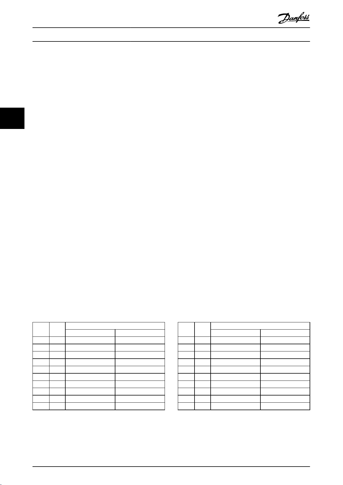
Table 4.1 Enclosure Power Ratings, 380–500 V
1) All power ratings are taken at high overload.
Output is measured at 400 V (kW) and 460 V (hp).
12 Danfoss A/S © 11/2017 All rights reserved. MG34S302
Table 4.2 Enclosure Power Ratings, 525–690 V
1) All power ratings are taken at high overload.
Output is measured at 690 V (kW) and 575 V (hp).
Page 15
Product Overview Design Guide
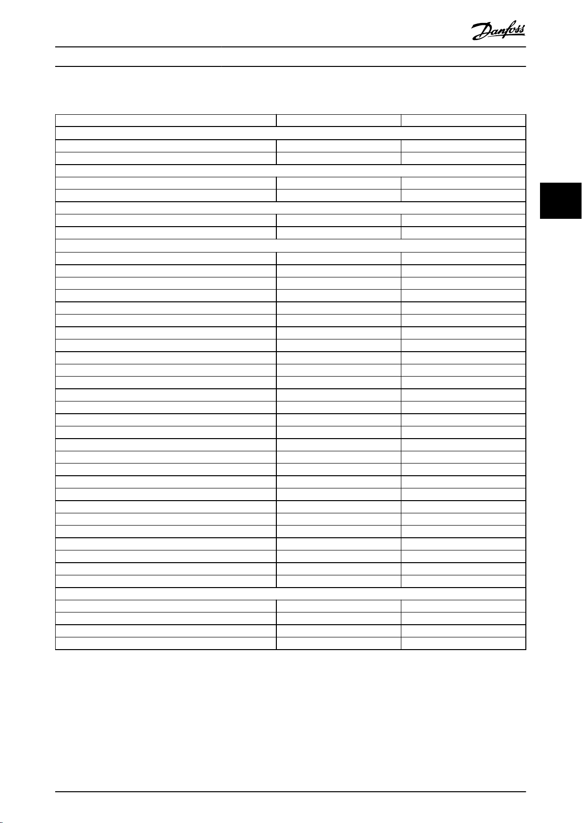
4.3 Overview of Enclosures, 380–500 V
Enclosure size E1 E2
Power rating
Output at 400 V (kW) 315–400 315–400
Output at 460 V (hp) 450–550 450–550
Front-end conguration
6-pulse S S
12-pulse – –
Protection rating
IP IP21/54 IP00
UL type Type 1/12 Chassis
Hardware options
Stainless steel back channel – O
Mains shielding O –
Space heater and thermostat – –
Cabinet light with power outlet – –
RFI lter (Class A1) O O
NAMUR terminals – –
Insulation resistance monitor (IRM) – –
Residual current monitor (RCM) – –
Brake chopper (IGBTs) O O
Safe Torque O S S
Regen terminals O O
Common motor terminals – –
Emergency stop with Pilz safety relay – –
Safe Torque O with Pilz safety relay – –
No LCP – –
Graphical LCP S S
Numerical LCP O O
Fuses O O
Load share terminals O O
Fuses + load share terminals O O
Disconnect O O
Circuit breakers – –
Contactors – –
Manual motor starters – –
30 A, fuse-protected terminals – –
24 V DC supply (SMPS, 5 A) O O
External temperature monitoring – –
Dimensions
Height, mm (in) 2000 (78.8) 1547 (60.9)
Width, mm (in) 600 (23.6) 585 (23.0)
Depth, mm (in) 494 (19.4) 498 (19.5)
Weight, kg (lb) 270–313 (595–690) 234–277 (516–611)
1)
3)
4 4
Table 4.3 E1–E2 Drives, 380–500 V
1) All power ratings are taken at high overload. Output is measured at 400 V (kW) and 460 V (hp).
2) If the enclosure is congured with load share or regen terminals, the protection rating is IP00, otherwise the protection rating is IP20.
3) S = standard, O = optional, and a dash indicates that the option is unavailable.
MG34S302 Danfoss A/S © 11/2017 All rights reserved. 13
Page 16

Product Overview
Enclosure size F1 F2 F3 F4
Power rating
Output at 400 V (kW) 315–400 450–500 315–400 450–500
Output at 460 V (hp) 450–550 600–650 450–550 600–650
Front-end conguration
6-pulse S S S S
12-pulse – – – –
Protection rating
44
IP IP21/54 IP21/54 IP21/54 IP21/54
UL type Type 1/12 Type 1/12 Type 1/12 Type 1/12
Hardware options
Stainless steel back channel O O O O
Mains shielding – – – –
Space heater and thermostat O O O O
Cabinet light with power outlet O O O O
RFI lter (Class A1) – – O O
NAMUR terminals O O O O
Insulation resistance monitor (IRM) – – O O
Residual current monitor (RCM) – – O O
Brake chopper (IGBTs) O O O O
Safe Torque O S S S S
Regen terminals O O O O
Common motor terminals O O O O
Emergency stop with Pilz safety relay – – O O
Safe Torque O with Pilz safety relay O O O O
No LCP – – – –
Graphical LCP S S S S
Numerical LCP – – – –
Fuses O O O O
Load share terminals O O O O
Fuses + load share terminals O O O O
Disconnect – – O O
Circuit breakers – – O O
Contactors – – O O
Manual motor starters O O O O
30 A, fuse-protected terminals O O O O
24 V DC supply (SMPS, 5 A) O O O O
External temperature monitoring O O O O
Dimensions
Height, mm (in) 2204 (86.8) 2204 (86.8) 2204 (86.8) 2204 (86.8)
Width, mm (in) 1400 (55.1) 1800 (70.9) 2000 (78.7) 2400 (94.5)
Depth, mm (in) 606 (23.9) 606 (23.9) 606 (23.9) 606 (23.9)
Weight, kg (lb) 1017 (2242.1) 1260 (2777.9) 1318 (2905.7) 1561 (3441.5)
1)
3)
VLT® AutomationDrive FC 302
315–1200 kW
Table 4.4 F1–F4 Drives, 380–500 V
1) All power ratings are taken at high overload. Output is measured at 400 V (kW) and 460 V (hp).
2) If the enclosure is
3) S = standard, O = optional, and a dash indicates that the option is unavailable.
14 Danfoss A/S © 11/2017 All rights reserved. MG34S302
congured with load share or regen terminals, the protection rating is IP00, otherwise the protection rating is IP20.
Page 17
Product Overview Design Guide
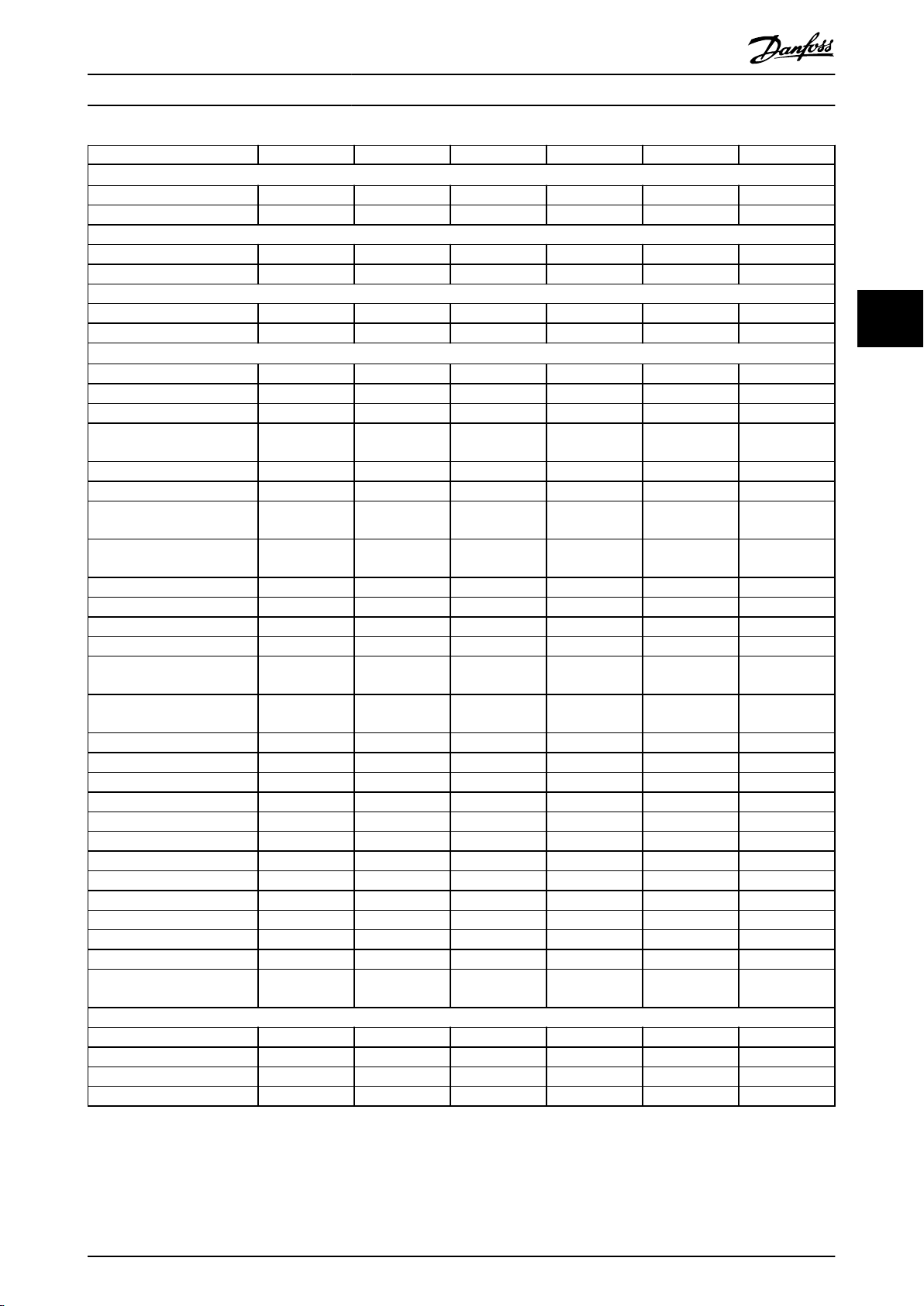
Enclosure size F8 F9 F10 F11 F12 F13
Power rating
Output at 400 V (kW) 90–132 160–250 450–630 450–630 710–800 710–800
Output at 460 V (hp) 125–200 250–350 600–900 600–900 1000–1200 1000–1200
Front-end conguration
6-pulse – – – – – –
12-pulse S S S S S S
Protection rating
IP IP21/54 IP21/54 IP21/54 IP21/54 IP21/54 IP21/54
NEMA Type 1/12 Type 1/12 Type 1/12 Type 1/12 Type 1/12 Type 1/12
Hardware options
Stainless steel back channel – – – – – –
Mains shielding – – – – – –
Space heater and thermostat – – O O O O
Cabinet light with power
outlet
RFI lter (Class A1) – O – – O O
NAMUR terminals O O O O O O
Insulation resistance monitor
(IRM)
Residual current monitor
(RCM)
Brake chopper (IGBTs) O O O O O O
Safe Torque O S S S S S S
Regen terminals – – – – – –
Common motor terminals – – O O O O
Emergency stop with Pilz
safety relay
Safe Torque O with Pilz
safety relay
No LCP – – – – – –
Graphical LCP S S S S S S
Numerical LCP – – – – – –
Fuses O O O O O O
Load share terminals – – – – – –
Fuses + load share terminals – – – – – –
Disconnect – O O O O O
Circuit breakers – – – – – –
Contactors – – – – – –
Manual motor starters – – O O O O
30 A, fuse-protected terminals – – O O O O
24 V DC supply (SMPS, 5 A) O O O O O O
External temperature
monitoring
Dimensions
Height, mm (in) 2204 (86.8) 2204 (86.8) 2204 (86.8) 2204 (86.8) 2204 (86.8) 2204 (86.8)
Width, mm (in) 800 (31.5) 1400 (55.2) 1600 (63.0) 2400 (94.5) 2000 (78.7) 2800 (110.2)
Depth, mm (in) 606 (23.9) 606 (23.9) 606 (23.9) 606 (23.9) 606 (23.9) 606 (23.9)
Weight, kg (lb) 447 (985.5) 669 (1474.9) 893 (1968.8) 1116 (2460.4) 1037 (2286.4) 1259 (2775.7)
1)
2)
– – O O O O
– O – – O O
– O – – O O
– – – – – –
O O O O O O
– – O O O O
4 4
Table 4.5 F8–F13 Drives, 380–500 V
1) All power ratings are taken at high overload. Output is measured at 400 V (kW) and 460 V (hp).
2) S = standard, O = optional, and a dash indicates that the option is unavailable.
MG34S302 Danfoss A/S © 11/2017 All rights reserved. 15
Page 18
Product Overview
VLT® AutomationDrive FC 302
315–1200 kW
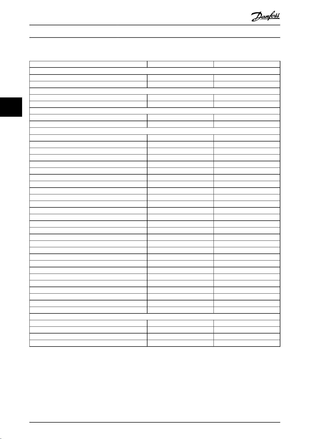
4.4 Overview of Enclosures, 525–690 V
Enclosure size E1 E2
Power rating
Output at 690 V (kW) 355–560 355–560
Output at 575 V (hp) 400–600 400–600
Front-end conguration
6-pulse S S
44
12-pulse – –
Protection rating
IP IP21/54 IP00
UL type Type 1/12 Chassis
Hardware options
Stainless steel back channel – O
Mains shielding O –
Space heater and thermostat – –
Cabinet light with power outlet – –
RFI lter (Class A1) O O
NAMUR terminals – –
Insulation resistance monitor (IRM) – –
Residual current monitor (RCM) – –
Brake chopper (IGBTs) O O
Safe Torque O S S
Regen terminals O O
Common motor terminals – –
Emergency stop with Pilz safety relay – –
Safe Torque O with Pilz safety relay – –
No LCP – –
Graphical LCP S S
Numerical LCP O O
Fuses O O
Load share terminals O O
Fuses + load share terminals O O
Disconnect O O
Circuit breakers – –
Contactors – –
Manual motor starters – –
30 A, fuse-protected terminals – –
24 V DC supply (SMPS, 5 A) O O
External temperature monitoring – –
Dimensions
Height, mm (in) 2000 (78.8) 1547 (60.9)
Width, mm (in) 600 (23.6) 585 (23.0)
Depth, mm (in) 494 (19.4) 498 (19.5)
Weight, kg (lb) 263–313 (580–690) 221–277 (487–611)
1)
3)
Table 4.6 E1–E2 Drives, 525–690 V
1) All power ratings are taken at high overload. Output is measured at 690 V (kW) and 575 V (hp).
2) If the enclosure is congured with load share or regen terminals, the protection rating is IP00, otherwise the protection rating is IP20.
3) S = standard, O = optional, and a dash indicates that the option is unavailable.
16 Danfoss A/S © 11/2017 All rights reserved. MG34S302
Page 19

Product Overview Design Guide
Enclosure size F1 F2 F3 F4
Power rating
Output at 690 V (kW) 630–800 900–1200 630–800 900–1200
Output at 575 V (hp) 650–950 1050–1350 650–950 1050–1350
Front-end conguration
6-pulse S S S S
12-pulse – – – –
Protection rating
IP IP21/54 IP21/54 IP21/54 IP21/54
UL type Type 1/12 Type 1/12 Type 1/12 Type 1/12
Hardware options
Stainless steel back channel O O O O
Mains shielding – – – –
Space heater and thermostat O O O O
Cabinet light with power outlet O O O O
RFI lter (Class A1) – – O O
NAMUR terminals O O O O
Insulation resistance monitor (IRM) – – O O
Residual current monitor (RCM) – – O O
Brake chopper (IGBTs) O O O O
Safe Torque O S S S S
Regen terminals O O O O
Common motor terminals O O O O
Emergency stop with Pilz safety relay – – O O
Safe Torque O with Pilz safety relay O O O O
No LCP – – – –
Graphical LCP S S S S
Numerical LCP – – – –
Fuses O O O O
Load share terminals O O O O
Fuses + load share terminals O O O O
Disconnect – – O O
Circuit breakers – – O O
Contactors – – O O
Manual motor starters O O O O
30 A, fuse-protected terminals O O O O
24 V DC supply (SMPS, 5 A) O O O O
External temperature monitoring O O O O
Dimensions
Height, mm (in) 2204 (86.8) 2204 (86.8) 2204 (86.8) 2204 (86.8)
Width, mm (in) 1400 (55.1) 1800 (70.9) 2000 (78.7) 2400 (94.5)
Depth, mm (in) 606 (23.9) 606 (23.9) 606 (23.9) 606 (23.9)
Weight, kg (lb) 1017 (2242.1) 1260 (2777.9) 1318 (2905.7) 1561 (3441.5)
1)
3)
4 4
Table 4.7 F1–F4 Drives, 525–690 V
1) All power ratings are taken at high overload. Output is measured at 690 V (kW) and 575 V (hp).
2) If the enclosure is
3) S = standard, O = optional, and a dash indicates that the option is unavailable.
MG34S302 Danfoss A/S © 11/2017 All rights reserved. 17
congured with load share or regen terminals, the protection rating is IP00, otherwise the protection rating is IP20.
Page 20

Product Overview
Enclosure size F8 F9 F10 F11 F12 F13
Power rating
Output at 690 V (kW) 355–560 355–560 630–800 630–800 900–1200 900–1200
Output at 575 V (hp) 400–600 400–600 650–950 650–950 1050–1350 1050–1350
Front-end conguration
6-pulse – – – – – –
12-pulse S S S S S S
Protection rating
44
IP IP21/54 IP21/54 IP21/54 IP21/54 IP21/54 IP21/54
NEMA Type 1/12 Type 1/12 Type 1/12 Type 1/12 Type 1/12 Type 1/12
Hardware options
Stainless steel back channel – – – – – –
Mains shielding – – – – – –
Space heater and thermostat – – O O O O
Cabinet light with power
outlet
RFI lter (Class A1) – O – – O O
NAMUR terminals O O O O O O
Insulation resistance monitor
(IRM)
Residual current monitor
(RCM)
Brake chopper (IGBTs) O O O O O O
Safe Torque O S S S S S S
Regen terminals – – – – – –
Common motor terminals – – O O O O
Emergency stop with Pilz
safety relay
Safe Torque O with Pilz
safety relay
No LCP – – – – – –
Graphical LCP S S S S S S
Numerical LCP – – – – – –
Fuses O O O O O O
Load share terminals – – – – – –
Fuses + load share terminals – – – – – –
Disconnect – O O O O O
Circuit breakers – – – – – –
Contactors – – – – – –
Manual motor starters – – O O O O
30 A, fuse-protected terminals – – O O O O
24 V DC supply (SMPS, 5 A) O O O O O O
External temperature
monitoring
Dimensions
Height, mm (in) 2204 (86.8) 2204 (86.8) 2204 (86.8) 2204 (86.8) 2204 (86.8) 2204 (86.8)
Width, mm (in) 800 (31.5) 1400 (55.1) 1600 (63.0) 2400 (94.5) 2000 (78.7) 2800 (110.2)
Depth, mm (in) 606 (23.9) 606 (23.9) 606 (23.9) 606 (23.9) 606 (23.9) 606 (23.9)
Weight, kg (lb) 447 (985.5) 669 (1474.9) 893 (1968.8) 1116 (2460.4) 1037 (2286.4) 1259 (2775.7)
1)
2)
– – O O O O
– O – – O O
– O – – O O
– – – – – –
O O O O O O
– – O O O O
VLT® AutomationDrive FC 302
315–1200 kW
Table 4.8 F8–F13 Drives, 525–690 V
1) All power ratings are taken at high overload. Output is measured at 690 V (kW) and 575 V (hp).
2) S = standard, O = optional, and a dash indicates that the option is unavailable.
18 Danfoss A/S © 11/2017 All rights reserved. MG34S302
Page 21
Product Overview Design Guide
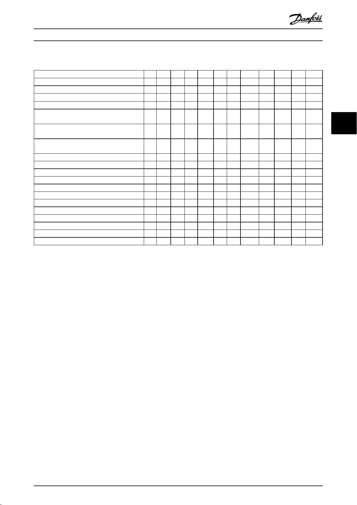
4.5 Kit Availability
Kit description
USB in door O – O O O O O O O O O O
LCP, numerical O O O O O O O O O O O O
LCP, graphical
LCP cable, 3 m (9 ft) O O O O O O O O O O O O
Mounting kit for numerical LCP
(LCP, fasteners, gasket, and cable)
Mounting kit for graphical LCP
(LCP, fasteners, gasket, and cable)
Mounting kit for all LCPs
(fasteners, gasket, and cable)
Top entry for motor cables – – O O O O O O O O O O
Top entry for mains cables – – O O O O O O O O O O
Top entry for mains cables with disconnect – – – – O O – – – – – –
Top entry for eldbus cables – O – – – – – – – – – –
Common motor terminals – – O O O O – – – – – –
NEMA 3R enclosure – O – – – – – – – – – –
Pedestal O O – – – – – – – – – –
Input options plate O O – – – – – – – – – –
IP20 conversion – O – – – – – – – – – –
Out top (only) cooling – O – – – – – – – – – –
Back-channel cooling (in-back/out-back) O O O O O O O O O O O O
Back-channel cooling (in-bottom/out-top) – O – – – – – – – – – –
1)
2)
E1 E2 F1 F2 F3 F4 F8 F9 F10 F11 F12 F13
O O O O O O O O O O O O
O O O O O O O O O O O O
O O O O O O O O O O O O
O O O O O O O O O O O O
4 4
Table 4.9 Available Kits for Enclosures E1–E2, F1–F4, and F8–F13
1) S = standard, O = optional, and a dash indicates that the kit is unavailable for that enclosure. For kit descriptions and part numbers, see
chapter 13.2 Ordering Numbers for Options/Kits.
2) The graphical LCP comes standard with enclosures E1–E2, F1–F4, and F8–F13. If more than 1 graphical LCP is required, the kit is available for
purchase.
MG34S302 Danfoss A/S © 11/2017 All rights reserved. 19
Page 22

Product Features
VLT® AutomationDrive FC 302
315–1200 kW
5 Product Features
Incorrect slip compensation setting causing
5.1 Automated Operational Features
Automated operational features are active when the drive
is operating. Most of them require no programming or setup. The drive has a range of built-in protection functions
to protect itself and the motor when it runs.
For details of any set-up required, in particular motor
55
parameters, refer to the programming guide.
5.1.1 Short-circuit Protection
Motor (phase-to-phase)
The drive is protected against short circuits on the motor
side by current measurement in each of the 3 motor
phases. A short circuit between 2 output phases causes an
overcurrent in the inverter. The inverter is turned o when
the short circuit current exceeds the allowed value (Alarm
16, Trip Lock).
Mains side
A drive that works correctly limits the current it can draw
from the supply. Still, it is recommended to use fuses
and/or circuit breakers on the supply side as protection if
there is component break-down inside the drive (1st fault).
Mains side fuses are mandatory for UL compliance.
NOTICE
To ensure compliance with IEC 60364 for CE or NEC 2009
for UL, it is mandatory to use fuses and/or circuit
breakers.
Brake resistor
The drive is protected from a short circuit in the brake
resistor.
Load sharing
To protect the DC bus against short circuits and the drives
from overload, install DC fuses in series with the load
sharing terminals of all connected units.
5.1.2 Overvoltage Protection
•
higher DC-link voltage.
Back EMF from PM motor operation. If coasted at
•
high RPM, the PM motor back EMF can
potentially exceed the maximum voltage
tolerance of the drive and cause damage. To help
prevent this situation, the value of
parameter 4-19 Max Output Frequency is automatically limited based on an internal calculation
based on the value of parameter 1-40 Back EMF at
1000 RPM, parameter 1-25 Motor Nominal Speed,
and parameter 1-39 Motor Poles.
NOTICE
To avoid motor overspeeds (for example, due to
excessive windmilling eects), equip the drive with a
brake resistor.
The overvoltage can be handled either using a brake
function (parameter 2-10 Brake Function) and/or using
overvoltage control (parameter 2-17 Over-voltage Control).
Brake functions
Connect a brake resistor for dissipation of surplus brake
energy. Connecting a brake resistor allows a higher DC-link
voltage during braking.
AC brake is an alternative to improving braking without
using a brake resistor. This function controls an overmagnetization of the motor when the motor is acting as a
generator. Increasing the electrical losses in the motor
allows the OVC function to increase the braking torque
without exceeding the overvoltage limit.
NOTICE
AC brake is not as eective as dynamic braking with a
resistor.
Overvoltage control (OVC)
By automatically extending the ramp-down time, OVC
reduces the risk of the drive tripping due to an
overvoltage on the DC-link.
Motor-generated overvoltage
The voltage in the DC link is increased when the motor
acts as a generator. This situation occurs in following cases:
The load rotates the motor at constant output
•
frequency from the drive, that is, the load
generates energy.
During deceleration (ramp-down) if the inertia
•
moment is high, the friction is low, and the rampdown time is too short for the energy to be
dissipated as a loss throughout the drive system.
20 Danfoss A/S © 11/2017 All rights reserved. MG34S302
NOTICE
OVC can be activated for a PM motor with all control
core, PM VVC+, Flux OL, and Flux CL for PM Motors.
NOTICE
Do not enable OVC in hoisting applications.
Page 23

Product Features Design Guide
5.1.3 Missing Motor Phase Detection
The missing motor phase function (parameter 4-58 Missing
Motor Phase Function) is enabled by default to avoid motor
damage if a motor phase is missing. The default setting is
1000 ms, but it can be adjusted for faster detection.
5.1.4 Supply Voltage Imbalance Detection
Operation under severe supply voltage imbalance reduces
the lifetime of the motor and drive. If the motor is
operated continuously near nominal load, conditions are
considered severe. The default setting trips the drive if
there is supply voltage imbalance
(parameter 14-12 Function at Mains Imbalance).
5.1.5 Switching on the Output
Adding a switch to the output between the motor and the
drive is allowed, however fault messages can appear.
Danfoss does not recommend using this feature for 525–
690 V drives connected to an IT mains network.
5.1.6 Overload Protection
Torque limit
The torque limit feature protects the motor against
overload, independent of the speed. Torque limit is
controlled in parameter 4-16 Torque Limit Motor Mode and
parameter 4-17 Torque Limit Generator Mode. The time
before the torque limit warning trips is controlled in
parameter 14-25 Trip Delay at Torque Limit.
Current limit
The current limit is controlled in parameter 4-18 Current
Limit, and the time before the drive trips is controlled in
parameter 14-24 Trip Delay at Current Limit.
Speed limit
Minimum speed limit: Parameter 4-11 Motor Speed Low
Limit [RPM] or parameter 4-12 Motor Speed Low Limit [Hz]
limit the minimum operating speed range of the drive.
Maximum speed limit: Parameter 4-13 Motor Speed High
Limit [RPM] or parameter 4-19 Max Output Frequency limit
the maximum output speed the drive can provide.
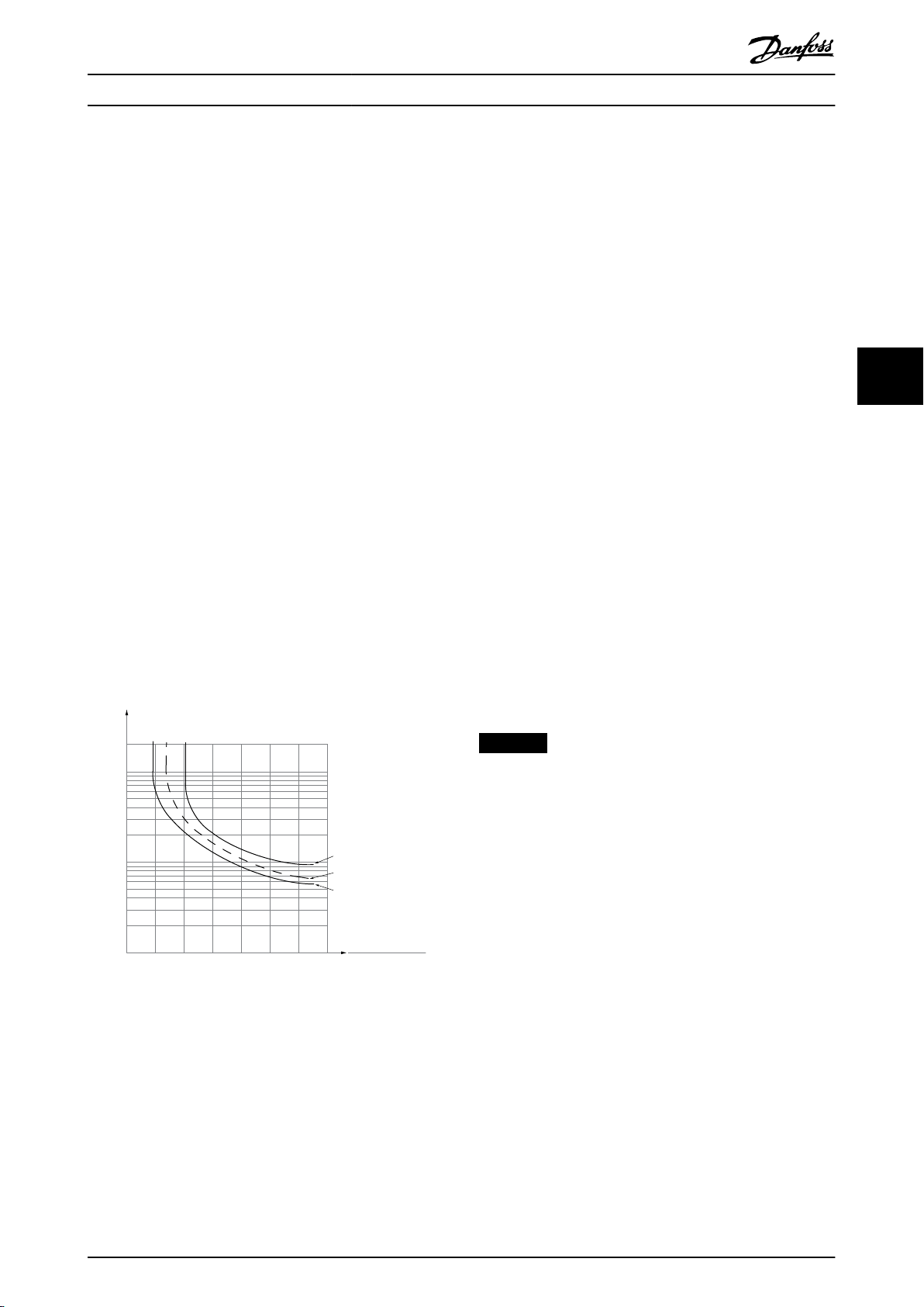
Electronic thermal relay (ETR)
ETR is an electronic feature that simulates a bimetal relay
based on internal measurements. The characteristic is
shown in Illustration 5.1.
Voltage limit
The inverter turns o to protect the transistors and the DC
link capacitors when a certain hard-coded voltage level is
reached.
Overtemperature
The drive has built-in temperature sensors and reacts
immediately to critical values via hard-coded limits.
5.1.7 Locked Rotor Protection
There can be situations when the rotor is locked due to
excessive load or other factors. The locked rotor cannot
produce enough cooling, which in turn can overheat the
motor winding. The drive is able to detect the locked rotor
situation with open-loop PM ux control and PM VVC
control (parameter 30-22 Locked Rotor Protection).
+
5.1.8 Automatic Derating
The drive constantly checks for the following critical levels:
High temperature on the control card or heat
•
sink.
High motor load.
•
High DC-link voltage.
•
Low motor speed.
•
As a response to a critical level, the drive adjusts the
switching frequency. For high internal temperatures and
low motor speed, the drives can also force the PWM
pattern to SFAVM.
NOTICE
The automatic derating is dierent when
parameter 14-55 Output Filter is set to [2] Sine-Wave Filter
Fixed.
5.1.9 Automatic Energy Optimization
Automatic energy optimization (AEO) directs the drive to
monitor the load on the motor continuously and adjust
the output voltage to maximize eciency. Under light
load, the voltage is reduced and the motor current is
minimized. The motor benets from:
Increased eciency.
•
Reduced heating.
•
Quieter operation.
•
There is no need to select a V/Hz curve because the drive
automatically adjusts motor voltage.
5.1.10 Automatic Switching Frequency
Modulation
The drive generates short electrical pulses to form an AC
wave pattern. The switching frequency is the rate of these
pulses. A low switching frequency (slow pulsing rate)
causes audible noise in the motor, making a higher
switching frequency preferable. A high switching
frequency, however, generates heat in the drive that can
limit the amount of current available to the motor.
Automatic switching frequency modulation regulates these
conditions automatically to provide the highest switching
5 5
MG34S302 Danfoss A/S © 11/2017 All rights reserved. 21
Page 24

Product Features
VLT® AutomationDrive FC 302
315–1200 kW
frequency without overheating the drive. By providing a
regulated high switching frequency, it quiets motor
operating noise at slow speeds, when audible noise control
is critical, and produces full output power to the motor
when required.
5.1.11 Automatic Derating for High
radiation from an external source. The drive is designed to
comply with the EMC product standard for drives IEC
61800-3 and the European standard EN 55011. Motor
cables must be shielded and properly terminated to
comply with the emission levels in EN 55011. For more
information regarding EMC performance, see
chapter 10.15.1 EMC Test Results.
Switching Frequency
5.1.16 Galvanic Isolation of Control
The drive is designed for continuous, full-load operation at
switching frequencies between 1.5–2 kHz for 380–500 V,
55
and 1–1.5 kHz for 525–690 V. The frequency range
depends on power size and voltage rating. A switching
frequency exceeding the maximum allowed range
generates increased heat in the drive and requires the
output current to be derated.
An automatic feature of the drive is load-dependent
switching frequency control. This feature allows the motor
to benet from as high a switching frequency as the load
allows.
All control terminals and output relay terminals are galvanically isolated from mains power, which completely
protects the controller circuitry from the input current. The
output relay terminals require their own grounding. This
isolation meets the stringent protective extra-low voltage
(PELV) requirements for isolation.
The components that make up the galvanic isolation
are:
5.1.12 Power Fluctuation Performance
The drive withstands mains uctuations such as:
Transients.
•
Momentary drop-outs.
•
Short voltage drops.
•
Surges.
•
The drive automatically compensates for input voltages
±10% from the nominal to provide full rated motor voltage
and torque. With auto restart selected, the drive automatically powers up after a voltage trip. With ying start, the
drive synchronizes to motor rotation before start.
5.1.13 Resonance Damping
Resonance damping eliminates the high-frequency motor
resonance noise. Automatic or manually selected frequency
damping is available.
5.2
Custom application functions are the most common
features programmed in the drive for enhanced system
performance. They require minimum programming or setup. See the programming guide for instructions on
activating these functions.
5.2.1 Automatic Motor Adaptation
Automatic motor adaptation (AMA) is an automated test
procedure used to measure the electrical characteristics of
the motor. AMA provides an accurate electronic model of
the motor, allowing the drive to calculate optimal
performance and eciency. Running the AMA procedure
also maximizes the automatic energy optimization feature
of the drive. AMA is performed without the motor rotating
and without uncoupling the load from the motor.
Terminals
Supply, including signal isolation.
•
Gatedrive for the IGBTs, trigger transformers, and
•
optocouplers.
The output current Hall
•
eect transducers.
Custom Application Features
5.1.14 Temperature-controlled Fans
5.2.2 Built-in PID Controller
Sensors in the drive regulate the operation of the internal
cooling fans. Often, the cooling fans do not run during low
load operation, or when in sleep mode or standby. These
sensors reduce noise, increase eciency, and extend the
operating life of the fan.
The built-in proportional, integral, derivative (PID)
controller eliminates the need for auxiliary control devices.
The PID controller maintains constant control of closedloop systems where regulated pressure, ow, temperature,
or other system requirements must be maintained.
5.1.15 EMC Compliance
dierent
Electromagnetic interference (EMI) and radio frequency
interference (RFI) are disturbances that can aect an
electrical circuit due to electromagnetic induction or
The drive can use 2 feedback signals from 2
devices, allowing the system to be regulated with dierent
feedback requirements. The drive makes control decisions
22 Danfoss A/S © 11/2017 All rights reserved. MG34S302
Page 25
1.21.0 1.4
30
10
20
100
60
40
50
1.81.6 2.0
2000
500
200
400
300
1000
600
t [s]
175ZA052.12
f
OUT
= 2 x f
M,N
f
OUT
= 0.2 x f
M,N
f
OUT
= 1 x f
M,N
(par. 1-23)
IMN(par. 1-24)
I
M
Product Features Design Guide
by comparing the 2 signals to optimize system
performance.
5.2.3 Motor Thermal Protection
Motor thermal protection can be provided via:
Direct temperature sensing using a
•
- PTC- or KTY sensor in the motor
windings and connected on a standard
AI or DI.
- PT100 or PT1000 in the motor windings
and motor bearings, connected on VLT
Sensor Input Card MCB 114.
-
PTC Thermistor input on VLT® PTC
Thermistor Card MCB 112 (ATEX
approved).
Mechanical thermal switch (Klixon type) on a DI.
•
Built-in electronic thermal relay (ETR).
•
ETR calculates motor temperature by measuring current,
frequency, and operating time. The drive shows the
thermal load on the motor in percentage and can issue a
warning at a programmable overload setpoint.
Programmable options at the overload allow the drive to
stop the motor, reduce output, or ignore the condition.
Even at low speeds, the drive meets I2t Class 20 electronic
motor overload standards.
and speed. The calculated temperature is visible as a
readout parameter in parameter 16-18 Motor Thermal.
A special version of the ETR is also available for EX-e
motors in ATEX areas. This function makes it possible to
enter a specic curve to protect the Ex-e motor. See the
programming guide for set-up instructions.
5.2.4 Motor Thermal Protection for Ex-e
Motors
The drive is equipped with an ATEX ETR thermal
®
monitoring function for operation of Ex-e motors according
to EN-60079-7. When combined with an ATEX approved
PTC monitoring device such as the VLT® PTC Thermistor
Card MCB 112 option or an external device, the installation
does not require an individual approval from an
approbated organization.
The ATEX ETR thermal monitoring function enables use of
an Ex-e motor instead of a more expensive, larger, and
heavier Ex-d motor. The function ensures that the drive
limits motor current to prevent overheating.
Requirements related to the Ex-e motor
Ensure that the Ex-e motor is approved for
•
operation in hazardous zones (ATEX zone 1/21,
ATEX zone 2/22) with drives. The motor must be
certied for the specic hazardous zone.
Install the Ex-e motor in zone 1/21 or 2/22 of the
•
hazardous zone, according to motor approval.
5 5
NOTICE
Install the drive outside the hazardous zone.
Ensure that the Ex-e motor is equipped with an
•
ATEX-approved motor overload protection device.
This device monitors the temperature in the
motor windings. If there is a critical temperature
level or a malfunction, the device switches o the
motor.
-
The VLT® PTC Thermistor Card MCB 112
option provides ATEX-approved
monitoring of motor temperature. It is a
Illustration 5.1 ETR Characteristics
The X-axis shows the ratio between I
nominal. The Y-axis shows the time in seconds before the
ETR cuts o and trips the drive. The curves show the
characteristic nominal speed, at twice the nominal speed
and at 0.2 x the nominal speed.
At lower speed, the ETR cuts o at lower heat due to less
cooling of the motor. In that way, the motor is protected
from being overheated even at low speed. The ETR feature
calculates the motor temperature based on actual current
MG34S302 Danfoss A/S © 11/2017 All rights reserved. 23
motor
and I
motor
Sine-wave lter is required when
•
prerequisite that the drive is equipped
with 3–6 PTC thermistors in series
according to DIN 44081 or 44082.
- Alternatively, an external ATEX-approved
PTC protection device can be used.
- Long cables (voltage peaks) or increased
mains voltage produce voltages
Page 26
130BD888.10
CONVERTER SUPPLY
VALID FOR 380 - 415V FWP 50Hz
3 ~ Motor
MIN. SWITCHING FREQ. FOR PWM CONV. 3kHz
l = 1.5XI
M,N
tOL = 10s tCOOL = 10min
MIN. FREQ. 5Hz MAX. FREQ. 85 Hz
PWM-CONTROL
f [Hz]
Ix/I
M,N
PTC °C DIN 44081/-82
Manufacture xx
EN 60079-0
EN 60079-7
СЄ 1180 Ex-e ll T3
5 15 25 50 85
0.4 0.8 1.0 1.0 0.95
1
xЗ
2
3
4
Product Features
VLT® AutomationDrive FC 302
315–1200 kW
exceeding the maximum allowable
voltage at motor terminals.
- Minimum switching frequency of the
drive does not meet the requirement
stated by the motor manufacturer. The
minimum switching frequency of the
drive is shown as the default value in
parameter 14-01 Switching Frequency.
Compatibility of motor and drive
For motors certied according to EN-60079-7, a data list
including limits and rules is supplied by the motor
55
manufacturer as a data sheet, or on the motor nameplate.
During planning, installation, commissioning, operation,
and service, follow the limits and rules supplied by the
manufacturer for:
Minimum switching frequency.
•
Maximum current.
•
Minimum motor frequency.
•
Maximum motor frequency.
•
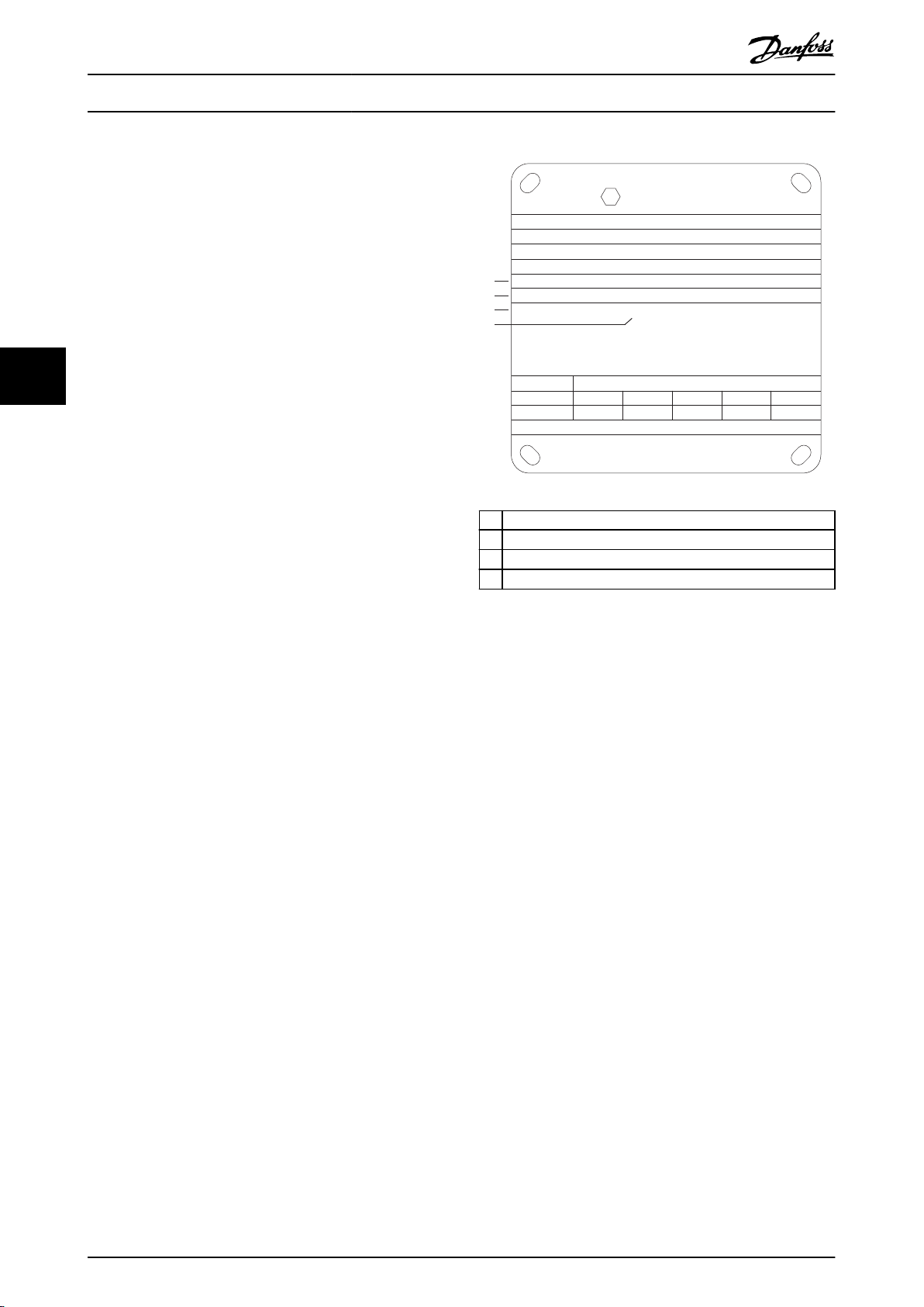
Illustration 5.2 shows where the requirements are indicated
on the motor nameplate.
1 Minimum switching frequency
2 Maximum current
3 Minimum motor frequency
4 Maximum motor frequency
When matching drive and motor, Danfoss species the
following extra requirements to ensure adequate motor
Illustration 5.2 Motor Nameplate showing Drive Requirements
thermal protection:
Do not exceed the maximum allowed ratio
•
between drive size and motor size. The typical
value is I
Consider all voltage drops from drive to motor. If
•
the motor runs with lower voltage than listed in
the U/f characteristics, current can increase,
triggering an alarm.
VLT, n
≤2xI
m,n
For further information, see the application example in
chapter 12 Application Examples.
5.2.5 Mains Drop-out
During a mains drop-out, the drive keeps running until the
DC-link voltage drops below the minimum stop level. The
minimum stop level is typically 15% below the lowest
rated supply voltage. The mains voltage before the dropout and the motor load determines how long it takes for
the drive to coast.
24 Danfoss A/S © 11/2017 All rights reserved. MG34S302
The drive can be congured (parameter 14-10 Mains Failure)
to dierent types of behavior during mains drop-out:
Trip lock once the DC link is exhausted.
•
Coast with ying start whenever mains return
•
(parameter 1-73 Flying Start).
Kinetic back-up.
•
Controlled ramp down.
•
Flying start
This selection makes it possible to catch a motor that is
spinning freely due to a mains drop-out. This option is
relevant for centrifuges and fans.
Kinetic back-up
This selection ensures that the drive runs as long as there
is energy in the system. For short mains drop-out, the
operation is restored after mains return, without bringing
Page 27
. . .
. . .
Par. 13-11
Comparator Operator
Par. 13-43
Logic Rule Operator 2
Par. 13-51
SL Controller Event
Par. 13-52
SL Controller Action
130BB671.13
Coast
Start timer
Set Do X low
Select set-up 2
. . .
Running
Warning
Torque limit
Digital input X 30/2
. . .
=
TRUE longer than..
. . .
. . .
Product Features Design Guide
the application to a stop or losing control at any time.
Several variants of kinetic back-up can be selected.
Congure the behavior of the drive at mains drop-out, in
parameter 14-10 Mains Failure and parameter 1-73 Flying
Start.
5.2.6 Automatic Restart
The drive can be programmed to restart the motor
automatically after a minor trip, such as momentary power
loss or uctuation. This feature eliminates the need for
manual resetting, and enhances automated operation for
remotely controlled systems. The number of restart
attempts and the duration between attempts can be
limited.
5.2.7 Full Torque at Reduced Speed
The drive follows a variable V/Hz curve to provide full
motor torque even at reduced speeds. Full output torque
can coincide with the maximum designed operating speed
of the motor. This drive diers from variable torque drives
and constant torque drives. Variable torque drives provide
reduced motor torque at low speed. Constant torque
drives provide excess voltage, heat, and motor noise at less
than full speed.
Set-up data can be copied from drive to drive by
downloading the information from the removable LCP.
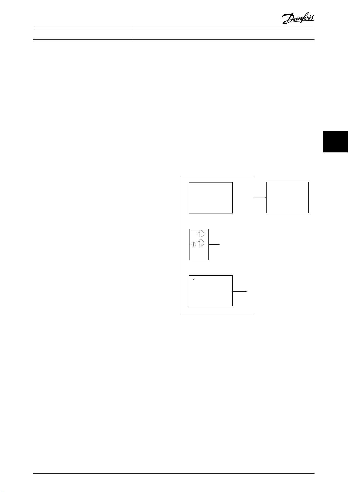
5.2.11 Smart Logic Control (SLC)
Smart logic control (SLC) is a sequence of user-dened
actions (see parameter 13-52 SL Controller Action [x])
executed by the SLC when the associated user-dened
event (see parameter 13-51 SL Controller Event [x]) is
evaluated as TRUE by the SLC.
The condition for an event can be a particular status, or
that the output from a logic rule or a comparator operand
becomes TRUE. The condition leads to an associated action
as shown in Illustration 5.3.
5 5
5.2.8 Frequency Bypass
In some applications, the system can have operational
speeds that create a mechanical resonance. This
mechanical resonance can generate excessive noise and
possibly damage mechanical components in the system.
The drive has 4 programmable bypass-frequency
bandwidths. The bandwidths allow the motor to step over
speeds that induce system resonance.
5.2.9 Motor Preheat
To preheat a motor in a cold or damp environment, a small
amount of DC current can be trickled continuously into the
motor to protect it from condensation and cold starts. This
function can eliminate the need for a space heater.
5.2.10 Programmable Set-ups
The drive has 4 set-ups that can be independently
programmed. Using multi-setup, it is possible to switch
between independently programmed functions activated
by digital inputs or a serial command. Independent set-ups
are used, for example, to change references, or for day/
night or summer/winter operation, or to control multiple
motors. The LCP shows the active set-up.
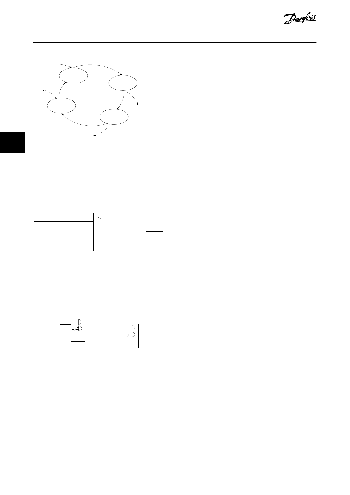
Illustration 5.3 SLC Event and Action
Events and actions are each numbered and linked in pairs
(states), which means that when event [0] is fullled
(attains the value TRUE), action [0] is executed. After the 1
action is executed, the conditions of the next event are
evaluated. If this event is evaluated as true, then the
corresponding action is executed. Only 1 event is
evaluated at any time. If an event is evaluated as false,
nothing happens in the SLC during the current scan
interval and no other events are evaluated. When the SLC
starts, it only evaluates event [0] during each scan interval.
Only when event [0] is evaluated as true, the SLC executes
action [0] and starts evaluating the next event. It is
possible to program 1–20 events and actions.
When the last event/action has been executed, the
sequence starts over again from event [0]/action [0].
Illustration 5.4 shows an example with 4 event/actions:
st
MG34S302 Danfoss A/S © 11/2017 All rights reserved. 25
Page 28
130BA062.14
State 1
13-51.0
13-52.0
State 2
13-51.1
13-52.1
Start
event P13-01
State 3
13-51.2
13-52.2
State 4
13-51.3
13-52.3
Stop
event P13-02
Stop
event P13-02
Stop
event P13-02
Par. 13-11
Comparator Operator
=
TRUE longer than.
. . .
. . .
Par. 13-10
Comparator Operand
Par. 13-12
Comparator Value
130BB672.10
. . .
. . .
. . .
. . .
Par. 13-43
Logic Rule Operator 2
Par. 13-41
Logic Rule Operator 1
Par. 13-40
Logic Rule Boolean 1
Par. 13-42
Logic Rule Boolean 2
Par. 13-44
Logic Rule Boolean 3
130BB673.10
Product Features
VLT® AutomationDrive FC 302
315–1200 kW
Liability conditions
The customer is responsible for ensuring that personnel
know how to install and operate the safe torque o
function by:
Reading and understanding the safety regulations
•
concerning health, safety, and accident
prevention.
Understanding the generic and safety guidelines
•
provided in the Safe Torque O Operating Guide.
Having a good knowledge of the generic and
•
safety standards for the specic application.
55
Illustration 5.4 Order of Execution when 4 Events/Actions are
Programmed
5.3 Dynamic Braking Overview
Dynamic braking slows the motor using 1 of the following
methods:
Comparators
Comparators are used for comparing continuous variables
(output frequency, output current, analog input, and so on)
to xed preset values.
AC brake
•
The brake energy is distributed in the motor by
changing the loss conditions in the motor
(parameter 2-10 Brake Function = [2]). The AC
brake function cannot be used in applications
with high cycling frequency since this situation
overheats the motor.
DC brake
•
An overmodulated DC current added to the AC
current works as an eddy current brake
(parameter 2-02 DC Braking Time ≠ 0 s).
Illustration 5.5 Comparators
Resistor brake
•
A brake IGBT keeps the overvoltage under a
certain threshold by directing the brake energy
Logic rules
Combine up to 3 boolean inputs (TRUE/FALSE inputs) from
timers, comparators, digital inputs, status bits, and events
using the logical operators AND, OR, and NOT.
from the motor to the connected brake resistor
(parameter 2-10 Brake Function = [1]). For more
information on selecting a brake resistor, see VLT
Brake Resistor MCE 101 Design Guide.
®
For drives equipped with the brake option, a brake IGBT
along with terminals 81(R-) and 82(R+) are included for
connecting an external brake resistor.
The function of the brake IGBT is to limit the voltage in the
DC link whenever the maximum voltage limit is exceeded.
It limits the voltage by switching the externally mounted
resistor across the DC bus to remove excess DC voltage
Illustration 5.6 Logic Rules
present on the bus capacitors.
External brake resistor placement has the advantages of
5.2.12 Safe Torque O
selecting the resistor based on application need,
dissipating the energy outside of the control panel, and
The Safe Torque O (STO) function is used to stop the
drive in emergency stop situations.
For more information about Safe Torque O, including
installation and commissioning, refer to the Safe Torque O
Operating Guide.
26 Danfoss A/S © 11/2017 All rights reserved. MG34S302
protecting the drive from overheating if the brake resistor
is overloaded.
The brake IGBT gate signal originates on the control card
and is delivered to the brake IGBT via the power card and
gatedrive card. Also, the power and control cards monitor
the brake IGBT for a short circuit. The power card also
monitors the brake resistor for overloads.
Page 29

Product Features Design Guide
5.4 Mechanical Holding Brake Overview
A mechanical holding brake is an external piece of equipment mounted directly on the motor shaft that performs static
braking. Static braking is when a brake is used to clamp down on the motor after the load has been stopped. A holding
brake is either controlled by a PLC or directly by a digital output from the drive.
NOTICE
A drive cannot provide a safe control of a mechanical brake. A redundancy circuitry for the brake control must be
included in the installation.
5.4.1 Mechanical Brake Using Open-loop Control
For hoisting applications, typically it is necessary to control an electromagnetic brake. A relay output (relay 1 or relay 2) or a
programmed digital output (terminal 27 or 29) is required. Normally, this output must be closed for as long as the drive is
unable to hold the motor. In parameter 5-40 Function Relay (array parameter), parameter 5-30 Terminal 27 Digital Output, or
parameter 5-31 Terminal 29 Digital Output, select [32] mechanical brake control for applications with an electromagnetic brake.
When [32] mechanical brake control is selected, the mechanical brake relay remains closed during start until the output
current is above the level selected in parameter 2-20 Release Brake Current. During stop, the mechanical brake closes when
the speed is below the level selected in parameter 2-21 Activate Brake Speed [RPM]. If the drive is brought into an alarm
condition, such as an overvoltage situation, the mechanical brake immediately cuts in. The mechanical brake also cuts in
during safe torque o.
Consider the following when using the electromagnetic brake:
Use any relay output or digital output (terminal 27 or 29). If necessary, use a contactor.
•
Ensure that the output is switched
•
being too heavy or the motor not being mounted.
Before connecting the mechanical brake, select [32] Mechanical brake control in parameter group 5-4* Relays (or in
•
parameter group 5-3* Digital Outputs).
The brake is released when the motor current exceeds the preset value in parameter 2-20 Release Brake Current.
•
The brake is engaged when the output frequency is less than the frequency set in parameter 2-21 Activate Brake
•
Speed [RPM] or parameter 2-22 Activate Brake Speed [Hz] and only if the drive carries out a stop command.
o as long as the drive is unable to rotate the motor. Examples include the load
5 5
NOTICE
For vertical lifting or hoisting applications, ensure that the load can be stopped if there is an emergency or a
malfunction. If the drive is in alarm mode or in an overvoltage situation, the mechanical brake cuts in.
For hoisting applications, make sure that the torque limits in parameter 4-16 Torque Limit Motor Mode and
parameter 4-17 Torque Limit Generator Mode are set lower than the current limit in parameter 4-18 Current Limit. It is also
recommended to set parameter 14-25 Trip Delay at Torque Limit to 0, parameter 14-26 Trip Delay at Inverter Fault to 0, and
parameter 14-10 Mains Failure to [3] Coasting.
MG34S302 Danfoss A/S © 11/2017 All rights reserved. 27
Page 30

Start
term.18
1=on
0=o
Shaft speed
Start delay time
on
o
Brake delay time
Time
Output current
Relay 01
Pre-magnetizing
current or
DC hold current
Reaction time EMK brake
Par 2-20
Release brake current
Par 1-76 Start current/
Par 2-00 DC hold current
Par 1-74
Start speed
Par 2-21
Activate brake
speed
Mechanical brake
locked
Mechanical brake
free
Par 1-71
Par 2-23
130BA074.12
Product Features
VLT® AutomationDrive FC 302
315–1200 kW
55
Illustration 5.7 Mechanical Brake Control in Open Loop
5.4.2 Mechanical Brake Using Closed-loop Control
The VLT® AutomationDrive FC 302 features a mechanical brake control designed for hoisting applications and supports the
following functions:
2 channels for mechanical brake feedback, oering protection against unintended behavior resulting from a broken
•
cable.
Monitoring the mechanical brake feedback throughout the complete cycle. Monitoring helps protect the
•
mechanical brake - especially if more drives are connected to the same shaft.
No ramp up until feedback conrms that the mechanical brake is open.
•
Improved load control at stop.
•
The transition when motor takes over the load from the brake can be congured.
•
Parameter 1-72 Start Function [6] Hoist Mech. Brake Rel activates the hoist mechanical brake. The main dierence compared to
the regular mechanical brake control is that the hoist mechanical brake function has direct control over the brake relay.
Instead of setting a current to release the brake, the torque applied against the closed brake before release is dened.
Because the torque is dened directly, the set-up is more straightforward for hoisting applications.
The hoist mechanical brake strategy is based on the following 3-step sequence, where motor control and brake release are
synchronized to obtain the smoothest possible brake release.
1. Pre-magnetize the motor.
To ensure that there is a hold on the motor and to verify that it is mounted correctly, the motor is
magnetized.
2. Apply torque against the closed brake.
rst pre-
28 Danfoss A/S © 11/2017 All rights reserved. MG34S302
Page 31

130BA642.12
A22
Active
W22
Active
W22
Active
A22
Active
High
Low
High
Low
Open
Closed
Motor
Speed
Torque
Ref.
Brake
Relay
Mech Brake
Feedback
Gain Boost or
Postion Control
Mech Brake
Position
Activate Brake
Delay
P. 2-23
Torque Ramp
Down Time
p. 2-29
Stop Delay
P. 2-24
Ramp 1 Down
P. 3-42
Ramp 1 Up
P. 3-41
Brake Release
Time
p. 2-25
Torque Ramp
Up Time
p. 2-27
Contact no.2
OPTIONAL
E.g. DI33 [71] Mech. Brake Feedback
Contact no.1
E.g. DI32 [70] Mech. Brake Feedback
Gain Boost. p. 2-28
Torque Ref. p. 2-26
Product Features Design Guide
When the load is held by the mechanical brake, its size cannot be determined, only its direction. The moment the
brake opens, the motor must take over the load. To facilitate the takeover, a user-dened torque
(parameter 2-26 Torque Ref) is applied in the hoisting direction. This process is used to initialize the speed controller
that nally takes over the load. To reduce wear on the gearbox due to backlash, the torque is ramped up.
3. Release the brake.
When the torque reaches the value set in parameter 2-26 Torque Ref, the brake is released. The value set in
parameter 2-25 Brake Release Time determines the delay before the load is released. To react as quickly as possible
on the load-step that follows after brake release, the speed-PID control can be boosted by increasing the proportional gain.
5 5
Illustration 5.8 Brake Release Sequence for Hoist Mechanical Brake Control
Parameter 2-26 Torque Ref to parameter 2-33 Speed PID Start Lowpass Filter Time are only available for the hoist mechanical
brake control (ux with motor feedback). Parameter 2-30 Position P Start Proportional Gain to parameter 2-33 Speed PID Start
Lowpass Filter Time can be set up for smooth transition change from speed control to position control during
parameter 2-25 Brake Release Time - the time when the load is transferred from the mechanical brake to the drive.
Parameter 2-30 Position P Start Proportional Gain to parameter 2-33 Speed PID Start Lowpass Filter Time are activated when
parameter 2-28 Gain Boost Factor is set to 0. See Illustration 5.8 for more information.
NOTICE
For an example of advanced mechanical brake control for hoisting applications, see chapter 12 Application Examples.
MG34S302 Danfoss A/S © 11/2017 All rights reserved. 29
Page 32

130BF758.10
380 V
2x aR-1000 A 2x aR-1500 A
3x 1.2%
315 kW 500 kW
3x 1.2%
3x Class L-800 A
3x Class L-1200 A
M
Common mains
disconnect switch
Mains connecting point for
additional drives in the
load sharing application
DC connecting point for
additional drives in the
load sharing application
91
92
93
91
92
93
96
97
98
96
97
98
82 81 82 81
M
Product Features
VLT® AutomationDrive FC 302
315–1200 kW
5.5 Load Share Overview
Load share is a feature that allows the connection of DC circuits of several drives, creating a multiple-drive system to run 1
mechanical load. Load share provides the following benets:
Energy savings
A motor running in regenerative mode can supply drives that are running in motoring mode.
Reduced need for spare parts
Usually, only 1 brake resistor is needed for the entire drive system instead of 1 brake resistor for per drive.
Power back-up
If there is mains failure, all linked drives can be supplied through the DC link from a back-up. The application can continue
55
running or go though a controlled shutdown process.
Preconditions
The following preconditions must be met before load sharing is considered:
The drive must be equipped with load sharing terminals.
•
Product series must be the same. Only VLT® AutomationDrive FC 302 drives used with other VLT® AutomationDrive
•
FC 302 drives.
Drives must be placed physically close to one another to allow the wiring between them to be no longer than
•
25 m (82 ft).
Drives must have the same voltage rating.
•
When adding a brake resistor in a load sharing conguration, all drives must be equipped with a brake chopper.
•
Fuses must be added to load share terminals.
•
For a diagram of a load share application in which best practices are applied, see Illustration 5.9.
Illustration 5.9 Diagram of a Load Share Application Where Best Practices are Applied
30 Danfoss A/S © 11/2017 All rights reserved. MG34S302
Page 33

Product Features Design Guide
Load sharing
Units with the built-in load sharing option contain terminals (+) 89 DC and (–) 88 DC. Within the drive, these terminals
connect to the DC bus in front of the DC-link reactor and bus capacitors.
The load sharing terminals can connect in 2 dierent congurations.
Terminals tie the DC-bus circuits of multiple drives together. This conguration allows a unit that is in a
•
regenerative mode to share its excess bus voltage with another unit that is running a motor. Load sharing in this
manner can reduce the need for external dynamic brake resistors, while also saving energy. The number of units
that can be connected in this way is innite, as long as each unit has the same voltage rating. In addition,
depending on the size and number of units, it may be necessary to install DC reactors and DC fuses in the DC-link
connections, and AC reactors on the mains. Attempting such a conguration requires specic considerations.
The drive is powered exclusively from a DC source. This conguration requires:
•
- A DC source.
- A means to soft charge the DC bus at power-up.
5.6 Regen Overview
Regen typically occurs in applications with continuous braking such as cranes/hoists, downhill conveyors, and centrifuges
where energy is pulled out of a decelerated motor.
5 5
The excess energy is removed from the drive using 1 of the following options:
Brake chopper allows the excess energy to be dissipated in the form of heat within the brake resistor coils.
•
Regen terminals allow a third-party regen unit to be connected to the drive, allowing the excess energy to be
•
returned to the power grid.
Returning excess energy back to the power grid is the most ecient use of regenerated energy in applications using
continuous braking.
MG34S302 Danfoss A/S © 11/2017 All rights reserved. 31
Page 34

Options and Accessories Ove...
VLT® AutomationDrive FC 302
315–1200 kW
6 Options and Accessories Overview
6
6.1 Fieldbus Devices
This section describes the eldbus devices that are
available with the VLT® AutomationDrive FC 302 series.
Using a eldbus device reduces system cost, delivers faster
and more ecient communication, and provides an easier
user interface. For ordering numbers, refer to
chapter 13.2 Ordering Numbers for Options/Kits.
6.1.1
VLT® PROFIBUS DP-V1 MCA 101
The MCA 101 provides:
Wide compatibility, a high level of availability,
•
support for all major PLC vendors, and compatibility with future versions.
Fast, ecient communication, transparent instal-
•
lation, advanced diagnosis, and parameterization
and auto-conguration of process data via a GSD
le.
Acyclic parameterization using PROFIBUS DP-V1,
•
PROFIdrive, or Danfoss FC
6.1.2
VLT® DeviceNet MCA 104
The MCA 104 provides:
Support of the ODVA AC drive prole supported
•
via I/O instance 20/70 and 21/71 secures compatibility to existing systems.
Benets from ODVA’s strong conformance testing
•
policies that ensure products are interoperable.
6.1.3
VLT® CAN Open MCA 105
The MCA 105 option provides:
Standardized handling.
•
Interoperability.
•
Low cost.
•
This option is fully equipped with both high-priority access
to control the drive (PDO communication) and to access all
parameters through acyclic data (SDO communication).
For interoperability, the option uses the DSP 402 AC drive
prole.
6.1.4
VLT® PROFIBUS Converter MCA 113
The MCA 113 option is a special version of the PROFIBUS
options that emulates the VLT® 3000 commands in the
VLT® AutomationDrive FC 302.
prole state machines.
®
The VLT
AutomationDrive FC 302, or an existing system can be
expanded without costly change of the PLC program. For
upgrade to a dierent eldbus, the installed converter can
be removed and replaced with a new option. The MCA 113
option secures the investment without losing exibility.
6.1.5
The MCA 114 option is a special version of the PROFIBUS
options that emulates the VLT® 5000 commands in the
VLT® AutomationDrive FC 302. This option supports DP-V1.
The VLT® 5000 can be replaced by the VLT
AutomationDrive FC 302, or an existing system can be
expanded without costly change of the PLC program. For
upgrade to a
be removed and replaced with a new option. The MCA 114
option secures the investment without losing exibility.
6.1.6
The MCA 120 option combines the highest performance
with the highest degree of openness. The option is
designed so that many of the features from the VLT
PROFIBUS MCA 101 can be reused, minimizing user
to migrate PROFINET and securing the investment in a PLC
program.
6.1.7
Ethernet is the future standard for communication at the
factory oor. The VLT® EtherNet/IP MCA 121 option is
based on the newest technology available for industrial
use and handles even the most demanding requirements.
3000 can be replaced by the VLT
VLT® PROFIBUS Converter MCA 114
dierent eldbus, the installed converter can
VLT® PROFINET MCA 120
Same PPO types as the VLT® PROFIBUS DP V1
•
MCA 101 for easy migration to PROFINET.
Built-in web server for remote diagnosis and
•
reading out of basic drive parameters.
Supports MRP.
•
Supports DP-V1. Diagnostic allows easy, fast, and
•
standardized handling of warning and fault
information into the PLC, improving bandwidth in
the system.
Supports PROFIsafe when combined with VLT
•
Safety Option MCB 152.
Implementation in accordance with Conformance
•
Class B.
VLT® EtherNet/IP MCA 121
®
®
®
eort
®
32 Danfoss A/S © 11/2017 All rights reserved. MG34S302
Page 35

Options and Accessories Ove... Design Guide
EtherNet/IP™ extends standard commercial Ethernet to the
Common Industrial Protocol (CIP™) – the same upper-layer
protocol and object model found in DeviceNet.
MCA 121 oers advanced features such as:
Built-in, high-performance switch enabling line-
•
topology, which eliminates the need for external
switches.
DLR Ring (from October 2015).
•
Advanced switch and diagnosis functions.
•
Built-in web server.
•
E-mail client for service notication.
•
Unicast and Multicast communication.
•
6.1.8
VLT® Modbus TCP MCA 122
The MCA 122 option connects to Modbus TCP-based
networks. It handles connection intervals down to 5 ms in
both directions, positioning it among the fastest
performing Modbus TCP devices in the market. For master
redundancy, it features hot swapping between 2 masters.
The option handles the EtherCAT line communication in
full speed, and connection towards the drive with an
interval down to 4 ms in both directions, allowing the MCA
124 to participate in networks ranging from low
performance up to servo applications.
EoE Ethernet over EtherCAT support.
•
HTTP (hypertext transfer protocol) for diagnosis
•
via built-in web server.
CoE (CAN over Ethernet) for access to drive
•
parameters.
SMTP (simple mail transfer protocol) for e-mail
•
notication.
TCP/IP for easy access to drive conguration data
•
from MCT 10.
6.2 Functional Extensions
This section describes the functional extension options that
are available with the VLT® AutomationDrive FC 302 series.
For ordering numbers, refer to chapter 13.2 Ordering
Numbers for Options/Kits.
6
6
Other features include:
Built-in web-server for remote diagnosis and
•
reading out basic drive parameters.
Email notication that can be congured to send
•
an email message to 1 or more recipients when
certain alarms or warnings occur, or when they
are cleared.
Dual master PLC connection for redundancy.
•
6.1.9
VLT® POWERLINK MCA 123
The MCA 123 option represents the 2nd generation of
eldbus. The high bit rate of industrial Ethernet can now
be used to make the full power of IT technologies used in
the automation world available for the factory world.
This eldbus option provides high performance, real-time,
and time synchronization features. Due to its CANopenbased communication models, network management, and
device description model, it oers a fast communication
network and the following features:
Dynamic motion control applications.
•
Material handling.
•
Synchronization and positioning applications.
•
6.1.10
The MCA 124 option oers connectivity to EtherCAT®
based networks via the EtherCAT Protocol.
VLT® EtherCAT MCA 124
6.2.1
VLT® General Purpose I/O Module
MCB 101
The MCB 101 option oers an extended number of control
inputs and outputs:
3 digital inputs 0–24 V: Logic 0 < 5 V; Logic 1 >
•
10 V.
2 analog inputs 0–10 V: Resolution 10 bits plus
•
sign.
2 digital outputs NPN/PNP push-pull.
•
1 analog output 0/4–20 mA.
•
Spring-loaded connection.
•
6.2.2
VLT® Encoder Input MCB 102
The MCB 102 option oers the possibility to connect
various types of incremental and absolute encoders. The
connected encoder can be used for closed-loop speed
control and closed-loop ux motor control.
The following encoder types are supported:
5 V TTL (RS 422)
•
1VPP SinCos
•
SSI
•
HIPERFACE
•
EnDat
•
MG34S302 Danfoss A/S © 11/2017 All rights reserved. 33
Page 36

Options and Accessories Ove...
VLT® AutomationDrive FC 302
315–1200 kW
6
6.2.3
VLT® Resolver Option MCB 103
The MCB 103 option enables connection of a resolver to
provide speed feedback from the motor.
Primary voltage: 2–8 V
•
Primary frequency: 2.0–15 kHz
•
Primary maximum current: 50 mA rms
•
Secondary input voltage: 4 V
•
Spring-loaded connection
•
6.2.4
VLT® Relay Card MCB 105
The MCB 105 option extends relay functions with 3 more
relay outputs.
Protects control cable connection.
•
Spring-loaded control wire connection.
•
Maximum switch rate (rated load/minimum load)
6 minutes-1/20 s-1.
Maximum terminal load
AC-1 resistive load: 240 V AC, 2 A.
6.2.5
VLT® Safe PLC Interface Option
rms
rms
MCB 108
The MCB 108 option provides a safety input based on a
single-pole 24 V DC input. For most applications, this input
provides a way to implement safety in a cost-eective way.
For applications that work with more advanced products
like Safety PLC and light curtains, the fail-safe PLC interface
enables the connection of a 2-wire safety link. The PLC
Interface allows the fail-safe PLC to interrupt on the plus or
the minus link without interfering with the sense signal of
the fail-safe PLC.
6.2.7
VLT® Sensor Input Option MCB 114
The MCB 114 option protects the motor from being
overheated by monitoring the temperature of motor
bearings and windings.
3 self-detecting sensor inputs for 2 or 3-wire
•
PT100/PT1000 sensors.
1 extra analog input 4–20 mA.
•
6.2.8
VLT® Safety Option MCB 150 and
MCB 151
MCB 150 and MCB 151 options expand the Safe Torque
functions, which are integrated in a standard VLT
AutomationDrive FC 302. Use the Safe Stop 1 (SS1)
function to perform a controlled stop before removing
torque. Use the Safety-Limited Speed (SLS) function to
monitor whether a specied speed is exceeded.
These options can be used up to PL d according to ISO
13849-1 and SIL 2 according to IEC 61508.
Extra standard-compliant safety functions.
•
Replacement of external safety equipment.
•
Reduced space requirements.
•
2 safe programmable inputs.
•
1 safe output (for T37).
•
Easier machine certication.
•
Drive can be powered continuously.
•
Safe LCP copy.
•
Dynamic commissioning report.
•
TTL (MCB 150) or HTL (MCB 151) encoder as
•
speed feedback.
6.2.9
VLT® Safety Option MCB 152
®
O
6.2.6
VLT® PTC Thermistor Card MCB 112
The MCB 112 option provides extra motor monitoring
compared to the built-in ETR function and thermistor
terminal.
Protects the motor from overheating.
•
ATEX-approved for use with Ex-d and Ex-e motors
•
(EX-e only FC 302).
Uses Safe Torque O function, which is approved
•
in accordance with SIL 2 IEC 61508.
34 Danfoss A/S © 11/2017 All rights reserved. MG34S302
The MCB 152 option activates Safe Torque O via the
PROFIsafe eldbus with VLT® PROFINET MCA 120 eldbus
option. It improves exibility by connecting safety devices
within a plant.
The safety functions of the MCB 152 are implemented
according to EN IEC 61800-5-2. The MCB 152 supports
PROFIsafe functionality to activate integrated safety
functions of the VLT® AutomationDrive FC 302 from any
PROFIsafe host, up to Safety Integrity Level SIL 2 according
to EN IEC 61508 and EN IEC 62061, and Performance Level
PL d, Category 3 according to EN ISO 13849-1.
PROFIsafe device (with MCA 120).
•
Replacement of external safety equipment.
•
Page 37

Options and Accessories Ove... Design Guide
2 safe programmable inputs.
•
Safe LCP copy.
•
Dynamic commissioning report.
•
6.3 Motion Control and Relay Cards
This section describes the motion control and relay card
options that are available with the VLT® AutomationDrive
FC 302 series. For ordering numbers, refer to
chapter 13.2 Ordering Numbers for Options/Kits.
6.3.1
VLT® Motion Control Option MCO 305
The MCO 305 option is an integrated programmable
motion controller that adds extra functionality for VLT
AutomationDrive FC 302.
The MCO 305 option oers easy-to-use motion functions
combined with programmability – an ideal solution for
positioning and synchronizing applications.
Synchronization (electronic shaft), positioning,
•
and electronic cam control.
2 separate interfaces supporting both incremental
•
and absolute encoders.
1 encoder output (virtual master function).
•
10 digital inputs.
•
8 digital outputs.
•
Supports CANopen motion bus, encoders, and I/O
•
modules.
Sends and receives data via
•
(requires eldbus option).
PC software tools for debugging and commis-
•
sioning: Program and cam editor.
Structured programming language with both
•
cyclic and event-driven execution.
6.3.2
VLT® Synchronizing Controller
eldbus interface
®
MCO 350
Control via I/Os or eldbus.
•
Home function.
•
Conguration and readout of status and data via
•
the LCP.
6.3.3
VLT® Positioning Controller MCO 351
The MCO 351 option oers a host of user-friendly benets
for positioning applications in many industries.
Relative positioning.
•
Absolute positioning.
•
Touch-probe positioning.
•
End-limit handling (software and hardware).
•
Control via I/Os or eldbus.
•
Mechanical brake handling (programmable hold
•
delay).
Error handling.
•
Jog speed/manual operation.
•
Marker-related positioning.
•
Home function.
•
Conguration and readout of status and data via
•
the LCP.
6.3.4
VLT® Extended Relay Card MCB 113
The MCB 113 option adds inputs/outputs for increased
exibility.
7 digital inputs.
•
2 analog outputs.
•
4 SPDT relays.
•
Meets NAMUR recommendations.
•
Galvanic isolation capability.
•
Brake Resistors
6.4
6
6
The MCO 350 option for VLT® AutomationDrive FC 302
expands the functional properties of the AC drive in
synchronizing applications and replaces traditional
mechanical solutions.
Speed synchronizing.
•
Position (angle) synchronizing with or without
•
marker correction.
On-line adjustable gear ratio.
•
On-line adjustable position (angle) oset.
•
Encoder output with virtual master function for
•
synchronization of multiple slaves.
MG34S302 Danfoss A/S © 11/2017 All rights reserved. 35
In applications where the motor is used as a brake, energy
is generated in the motor and sent back into the drive. If
the energy cannot be transported back to the motor, it
increases the voltage in the drive DC line. In applications
with frequent braking and/or high inertia loads, this
increase can lead to an overvoltage trip in the drive and,
nally, a shutdown. Brake resistors are used to dissipate
the excess energy resulting from the regenerative braking.
The resistor is selected based on its ohmic value, its power
dissipation rate, and its physical size. Danfoss oers a wide
variety of dierent resistors that are specially designed to
Danfoss drives. For ordering numbers and more
information on how to dimension brake resistors, refer to
the VLT® Brake Resistor MCE 101 Design Guide.
Page 38

Options and Accessories Ove...
VLT® AutomationDrive FC 302
315–1200 kW
6
6.5 Sine-wave Filters
When a drive controls a motor, resonance noise is heard
from the motor. This noise, which is the result of the motor
design, occurs every time an inverter switch in the drive is
activated. The frequency of the resonance noise thus
corresponds to the switching frequency of the drive.
Danfoss supplies a sine-wave
motor noise. The lter reduces the ramp-up time of the
voltage, the peak load voltage (U
current (ΔI) to the motor, which means that current and
voltage become almost sinusoidal. The acoustic motor
noise is reduced to a minimum.
The ripple current in the sine-wave
some noise. Solve the problem by integrating the lter in a
cabinet or enclosure.
For ordering numbers and more information on sine-wave
lters, refer to the Output Filters Design Guide.
lter to dampen the acoustic
), and the ripple
PEAK
lter coils also causes
6.6 dU/dt Filters
Danfoss supplies dU/dt lters which are dierential mode,
low-pass lters that reduce motor terminal phase-to-phase
peak voltages and reduce the rise time to a level that
lowers the stress on the insulation at the motor windings.
This is a typical issue with set-ups using short motor
cables.
Compared to sine-wave lters, the dU/dt lters have a cut-
o frequency above the switching frequency.
For ordering numbers and more information on dU/dt
lters, refer to the Output Filters Design Guide.
Common-mode Filters
6.7
High-frequency common-mode cores (HF-CM cores) reduce
electromagnetic interference and eliminate bearing
damage by electrical discharge. They are special nanocrystalline magnetic cores that have superior ltering
performance compared to regular ferrite cores. The HF-CM
core acts like a common-mode inductor between phases
and ground.
Installed around the 3 motor phases (U, V, W), the
common mode lters reduce high-frequency commonmode currents. As a result, high-frequency electromagnetic
interference from the motor cable is reduced.
For ordering numbers refer to the Output Filters Design
Guide.
Harmonic Filters
6.8
The VLT® Advanced Harmonic Filters AHF 005 & AHF 010
should not be compared with traditional harmonic trap
lters. The Danfoss harmonic lters have been specially
designed to match the Danfoss drives.
By connecting the AHF 005 or AHF 010 in front of a
Danfoss drive, the total harmonic current distortion
generated back to the mains is reduced to 5% and 10%.
For ordering numbers and more information on how to
dimension brake resistors, refer to the VLT® Advanced
Harmonic Filters AHF 005/AHF 010 Design Guide.
6.9 Enclosure Built-in Options
The following built-in options are specied in the type
code when ordering the drive.
Enclosure with corrosion-resistant back channel
For extra protection from corrosion in harsh environments,
units can be ordered in an enclosure that includes a
stainless steel back channel, heavier plated heat sinks, and
an upgraded fan. This option is recommended in salt-air
environments, such as those near the ocean.
Mains shielding
Lexan® shielding can be mounted in front of incoming
power terminals and input plate to protect against physical
contact when the enclosure door is open.
Space heaters and thermostat
Mounted in the cabinet interior of enclosure size F drives
and controlled via an automatic thermostat, space heaters
controlled via an automatic thermostat prevent condensation inside the enclosure.
The thermostat default settings turn on the heaters at
10 °C (50 °F) and turn them o at 15.6 °C (60 °F).
Cabinet light with power outlet
To increase visibility during servicing and maintenance, a
light can be mounted on the cabinet interior of enclosure
F drives. The light housing includes a power outlet for
temporarily powering laptop computers or other devices.
Available in 2 voltages:
230 V, 50 Hz, 2.5 A, CE/ENEC
•
120 V, 60 Hz, 5 A, UL/cUL
•
RFI lters
VLT® drive series feature integrated Class A2 RFI lters as
standard. If extra levels of RFI/EMC protection are required,
they can be obtained using optional Class A1 RFI lters,
which provide suppression of radio frequency interference
and electromagnetic radiation in accordance with EN
55011. Marine use RFI lters are also available.
On enclosure size F drives, the Class A1 RFI lter requires
the addition of the options cabinet.
36 Danfoss A/S © 11/2017 All rights reserved. MG34S302
Page 39

Options and Accessories Ove... Design Guide
NAMUR terminals
Selection of this option provides standardized terminal
connection and associated functionality as dened by
NAMUR NE37. NAMUR is an international association of
automation technology users in the process industries,
primarily chemical, and pharmaceutical industries in
Germany.
Requires the selection of VLT® Extended Relay Card MCB
113 and the VLT® PTC Thermistor Card MCB 112.
Insulation resistance monitor (IRM)
Monitors the insulation resistance in ungrounded systems
(IT systems in IEC terminology) between the system phase
conductors and ground. There is an ohmic pre-warning
and a main alarm setpoint for the insulation level.
Associated with each setpoint is an SPDT alarm relay for
external use. Only 1 insulation resistance monitor can be
connected to each ungrounded (IT) system.
Integrated into the safe-stop circuit.
•
LCD display of insulation resistance.
•
Fault memory.
•
Info, test, and reset key.
•
Residual current device (RCD)
Uses the core balance method to monitor ground fault
currents in grounded and high-resistance grounded
systems (TN and TT systems in IEC terminology). There is a
pre-warning (50% of main alarm setpoint) and a main
alarm setpoint. Associated with each setpoint is an SPDT
alarm relay for external use. Requires an external “windowtype” current transformer (supplied and installed by
customer).
Integrated into the safe-stop circuit.
•
IEC 60755 Type B device monitors, pulsed DC,
•
and pure DC ground fault currents.
LED bar graph indicator of the ground fault
•
current level from 10–100% of the setpoint.
Fault memory.
•
Test and reset key.
•
Safe Torque
Available for drives with enclosure size F. Enables the Pilz
relay to t in the enclosure without requiring an options
cabinet. The relay is used in the external temperature
monitoring option. If PTC monitoring is required, VLT® PTC
Thermistor Card MCB 112 must be ordered.
Emergency stop with Pilz safety relay
Includes a redundant 4-wire emergency stop push button
mounted on the front of the enclosure, and a Pilz relay
that monitors it along with the safe-stop circuit and
contactor position. Requires a contactor and the options
cabinet for drives with enclosure size F.
O with Pilz safety relay
Brake chopper (IGBTs)
Brake terminals with an IGBT brake chopper circuit allow
for the connection of external brake resistors. For detailed
data on brake resistors, see the VLT® Brake Resistor MCE
101 Design Guide, available at drives.danfoss.com/
downloads/portal/#/.
Regen terminals
Allow connection of regen units to the DC bus on the
capacitor bank side of the DC-link reactors for regenerative
braking. The enclosure size F regen terminals are sized for
approximately 50% the power rating of the drive. Consult
the factory for regen power limits based on the specic
drive size and voltage.
Load sharing terminals
These terminals connect to the DC-bus on the rectier side
of the DC-link reactor and allow for the sharing of DC bus
power between multiple drives. For drives with enclosure
size F, the load sharing terminals are sized for approximately 33% of the power rating of the drive. Consult the
factory for load sharing limits based on the specic drive
size and voltage.
Disconnect
A door-mounted handle allows for the manual operation of
a power disconnect switch to enable and disable power to
the drive, increasing safety during servicing. The
disconnect is interlocked with the cabinet doors to prevent
them from being opened while power is still applied.
Circuit breakers
A circuit breaker can be remotely tripped, but must be
manually reset. Circuit breakers are interlocked with the
cabinet doors to prevent them from being opened while
power is still applied. When a circuit breaker is ordered as
an option, fuses are also included for fast-acting current
overload protection of the AC drive.
Contactors
An electrically-controlled contactor switch allows for the
remote enabling and disabling of power to the drive. If the
IEC emergency stop option is ordered, the Pilz relay
monitors the auxiliary contact on the contactor.
Manual motor starters
Provide 3-phase power for electric cooling blowers that are
often required for larger motors. Power for the starters is
provided from the load side of any supplied contactor,
circuit breaker, or disconnect switch. If a Class 1 RFI
option is ordered, the input side of the RFI provides the
power to the starter. Power is fused before each motor
starter and is o when the incoming power to the drive is
o. Up to 2 starters are allowed. If a 30 A fuse-protected
circuit is ordered, then only 1 starter is allowed. Starters
are integrated into the safe-stop circuit.
Features include:
Operation switch (on/o).
•
Short circuit and overload protection with test
•
function.
lter
6
6
MG34S302 Danfoss A/S © 11/2017 All rights reserved. 37
Page 40

Options and Accessories Ove...
VLT® AutomationDrive FC 302
315–1200 kW
6
Manual reset function.
•
30 A, fuse-protected terminals
3-phase power matching incoming mains voltage
•
for powering auxiliary customer equipment.
Not available if 2 manual motor starters are
•
selected.
Terminals are o when the incoming power to
•
the drive is o.
Power for the terminals is provided from the load
•
side of any supplied contactor, circuit breaker, or
disconnect switch. If a Class 1 RFI lter option is
ordered, the input side of the RFI provides the
power to the starter.
Common motor terminals
The common motor terminal option provides the busbars
and hardware required to connect the motor terminals
from the paralleled inverters to a single terminal (per
phase) to accommodate the installation of the motor-side
top entry kit.
This option is also recommended to connect the output of
a drive to an output lter or output contactor. The
common motor terminals eliminate the need for equal
cable lengths from each inverter to the common point of
the output lter (or motor).
24 V DC supply
5 A, 120 W, 24 V DC.
•
Protected against output overcurrent, overload,
•
short circuits, and overtemperature.
For powering customer-supplied accessory
•
devices such as sensors, PLC I/O, contactors,
temperature probes, indicator lights, and/or other
electronic hardware.
Diagnostics include a dry DC-ok contact, a green
•
DC-ok LED, and a red overload LED.
External temperature monitoring
Designed for monitoring temperatures of external system
components, such as the motor windings and/or bearings.
Includes 8 universal input modules plus 2 dedicated
thermistor input modules. All 10 modules are integrated
into the safe-stop circuit and can be monitored via a
eldbus network, which requires the purchase of a
separate module/bus coupler. A safe torque o brake
option must be ordered when selecting external
temperature monitoring.
Signal types:
RTD inputs (including Pt100) – 3-wire or 4-wire.
•
Thermocouple.
•
Analog current or analog voltage.
•
More features:
1 universal output – congurable for analog
•
voltage or analog current.
2 output relays (NO).
•
Dual-line LC display and LED diagnostics.
•
Sensor lead wire break, short circuit, and incorrect
•
polarity detection.
Sensor lead wire break, short circuit, and incorrect
•
polarity detection.
Interface set-up software.
•
If 3 PTC are required, the VLT® PTC Thermistor
•
Card MCB 112 option must be added.
For ordering numbers for enclosure built-in options, refer
to chapter 13.1 Drive Congurator.
6.10 High-power Kits
High-power kits, such as back-wall cooling, space heater,
mains shield, are available. See chapter 13.2 Ordering
Numbers for Options/Kits for a brief description and
ordering numbers for all available kits.
38 Danfoss A/S © 11/2017 All rights reserved. MG34S302
Page 41

Specications Design Guide
7 Specications
7.1 Electrical Data, 380–500 V
VLT® AutomationDrive FC 302
High/normal overload HO NO HO NO HO NO
(High overload=150% current during 60 s,
normal overload=110% current during 60 s)
Typical shaft output at 400 V [kW] 315 355 355 400 400 450
Typical shaft output at 460 V [hp] 450 500 500 600 550 600
Typical shaft output at 500 V [kW] 355 400 400 500 500 530
Enclosure size E1/E2 E1/E2 E1/E2
Output current (3-phase)
Continuous (at 400 V) [A] 600 658 658 745 695 800
Intermittent (60 s overload) (at 400 V) [A] 900 724 987 820 1043 880
Continuous (at 460/500 V) [A] 540 590 590 678 678 730
Intermittent (60 s overload) (at 460/500 V) [A] 810 649 885 746 1017 803
Continuous kVA (at 400 V) [kVA] 416 456 456 516 482 554
Continuous kVA (at 460 V) [kVA] 430 470 470 540 540 582
Continuous kVA (at 500 V) [kVA] 468 511 511 587 587 632
Maximum input current
Continuous (at 400 V) [A] 578 634 634 718 670 771
Continuous (at 460/500 V) [A] 520 569 569 653 653 704
Maximum number and size of cables
per phase
Mains and motor [mm2 (AWG)]
Brake [mm2 (AWG)]
Load share [mm2 (AWG)]
Maximum external mains fuses [A]
Estimated power loss at 400 V [W]
Estimated power loss at 460 V [W]
Eciency
Output frequency [Hz] 0–590 0–590 0–590
Control card overtemperature trip [°C (°F)]
3)
1)
2), 3)
2), 3)
P315 P355 P400
4x240 (4x500 mcm) 4x240 (4x500 mcm) 4x240 (4x500 mcm)
2x185 (2x350 mcm) 2x185 (2x350 mcm) 2x185 (2x350 mcm)
4x240 (4x500 mcm) 4x240 (4x500 mcm) 4x240 (4x500 mcm)
900 900 900
6794 7532 7498 8677 7976 9473
6118 6724 6672 7819 7814 8527
0.98 0.98 0.98
85 (185) 85 (185) 85 (185)
7 7
Table 7.1 Electrical Data for Enclosures E1/E2, Mains Supply 3x380–500 V AC
1) For fuse ratings, see chapter 10.5 Fuses and Circuit Breakers.
±
2) Typical power loss is at normal conditions and expected to be within
values are based on a typical motor eciency (IE/IE3 border line). Lower eciency motors add to the power loss in the drive. Applies for
dimensioning of drive cooling. If the switching frequency is higher than the default setting, the power losses can increase. LCP and typical control
card power consumptions are included. For power loss data according to EN 50598-2, refer to drives.danfoss.com/knowledge-center/energy-
eciency-directive/#/. Options and customer load can add up to 30 W to the losses, though usually a fully loaded control card and options for
slots A and B each add only 4 W.
3) Measured using 5 m (16.5 ft) shielded motor cables at rated load and rated frequency. Eciency measured at nominal current. For energy
eciency class, see chapter 10.12 Eciency. For part load losses, see drives.danfoss.com/knowledge-center/energy-eciency-directive/#/.
MG34S302 Danfoss A/S © 11/2017 All rights reserved. 39
15% (tolerance relates to variety in voltage and cable conditions). These
Page 42

Specications
VLT® AutomationDrive FC 302
315–1200 kW
VLT® AutomationDrive FC 302
High/normal overload HO NO HO NO HO NO HO NO
(High overload=150% current during 60 s,
normal overload=110% current during 60 s)
Typical shaft output at 400 V [kW] 450 500 500 560 560 630 630 710
Typical shaft output at 460 V [hp] 600 650 650 750 750 900 1000 1000
Typical shaft output at 500 V [kW] 530 560 560 630 630 710 800 800
Enclosure size F1/F3 F1/F3 F1/F3 F1/F3
Output current (3-phase)
Continuous (at 400 V) [A] 800 880 880 990 990 1120 1120 1260
Intermittent (60 s overload)
(at 400 V) [A]
Continuous (at 460/500 V) [A] 730 780 780 890 890 1050 1050 1160
Intermittent (60 s overload)
(at 460/500 V) [A]
Continuous kVA (at 400 V) [kVA] 554 610 610 686 686 776 776 873
Continuous kVA (at 460 V) [kVA] 582 621 621 709 709 837 837 924
77
Continuous kVA (at 500 V) [kVA] 632 675 675 771 771 909 909 1005
Maximum input current
Continuous (at 400 V) [A] 771 848 848 954 954 1079 1079 1214
Continuous (at 460/500 V) [A] 704 752 752 858 858 1012 1012 1118
Maximum number and size of
cables per phase
- Motor [mm2 (AWG)]
- Mains [mm2 (AWG)] (F1)
- Mains [mm2 (AWG)] (F3)
- Load share [mm2 (AWG)]
- Brake [mm2 (AWG)]
Maximum external mains fuses [A]
Estimated power loss at 400 V [W]
Estimated power loss at 460 V [W]
Maximum added losses A1 RFI, circuit breaker
or disconnect, and contactor [W], (F3 only)
Maximum panel options losses [W] 400 400 400 400 400 400 400 400
Eciency
Output frequency [Hz] 0–590 0–590 0–590 0–590
Control card overtemperature trip [°C (°F)]
3)
1)
2), 3)
2), 3)
P450 P500 P560 P630
1200 968 1320 1089 1485 1680 1386 1890
1095 858 1170 979 1335 1155 1575 1276
8x150 (8x300 mcm) 8x150 (8x300 mcm) 8x150 (8x300 mcm) 8x150 (8x300 mcm)
8x240 (8x500 mcm) 8x240 (8x500 mcm) 8x240 (8x500 mcm) 8x240 (8x500 mcm)
8x456 (8x900 mcm) 8x456 (8x900 mcm) 8x456 (8x900 mcm) 8x456 (8x900 mcm)
4x120 (4x250 mcm) 4x120 (4x250 mcm) 4x120 (4x250 mcm) 4x120 (4x250 mcm)
4x185 (4x350 mcm) 4x185 (4x350 mcm) 4x185 (4x350 mcm) 4x185 (4x350 mcm)
1600 1600 2000 2000
9031 10162 10146 11822 10649 12512 12490 14674
8212 8876 8860 10424 9414 11595 11581 13213
893 963 951 1054 978 1093 1092 1230
0.98 0.98 0.98 0.98
85 (185) 85 (185) 85 (185) 85 (185)
Table 7.2 Electrical Data for Enclosures F1/F3, Mains Supply 3x380–500 V AC
1) For fuse ratings, see chapter 10.5 Fuses and Circuit Breakers.
±
2) Typical power loss is at normal conditions and expected to be within
values are based on a typical motor eciency (IE/IE3 border line). Lower eciency motors add to the power loss in the drive. Applies for
dimensioning of drive cooling. If the switching frequency is higher than the default setting, the power losses can increase. LCP and typical control
card power consumptions are included. For power loss data according to EN 50598-2, refer to drives.danfoss.com/knowledge-center/energy-
eciency-directive/#/. Options and customer load can add up to 30 W to the losses, though usually a fully loaded control card and options for
slots A and B each add only 4 W.
3) Measured using 5 m (16.5 ft) shielded motor cables at rated load and rated frequency. Eciency measured at nominal current. For energy
eciency class, see chapter 10.12 Eciency. For part load losses, see drives.danfoss.com/knowledge-center/energy-eciency-directive/#/.
40 Danfoss A/S © 11/2017 All rights reserved. MG34S302
15% (tolerance relates to variety in voltage and cable conditions). These
Page 43

Specications Design Guide
VLT® AutomationDrive FC 302
High/normal overload HO NO HO NO
(High overload=150% current during 60 s, normal overload=110%
current during 60 s)
Typical shaft output at 400 V [kW] 710 800 800 1000
Typical shaft output at 460 V [hp] 1000 1200 1200 1350
Typical shaft output at 500 V [kW] 800 1000 1000 1100
Enclosure size F2/F4 F2/F4
Output current (3-phase)
Continuous (at 400 V) [A] 1260 1460 1460 1720
Intermittent (60 s overload)
(at 400 V) [A]
Continuous (at 460/500 V) [A] 1160 1380 1380 1530
Intermittent (60 s overload)(at 460/500 V) [A] 1740 1518 2070 1683
Continuous kVA (at 400 V) [kVA] 873 1012 1012 1192
Continuous kVA (at 460 V) [kVA] 924 1100 1100 1219
Continuous kVA (at 500 V) [kVA] 1005 1195 1195 1325
Maximum input current
Continuous (at 400 V) [A] 1214 1407 1407 1658
Continuous (at 460/500 V) [A] 1118 1330 1330 1474
Maximum number and size of cables per phase
- Motor [mm2 (AWG)]
- Mains [mm2 (AWG)] (F2)
- Mains [mm2 (AWG)] (F4)
- Load share [mm2 (AWG)]
- Brake [mm2 (AWG)]
Maximum external mains fuses [A]
Estimated power loss at 400 V [W]
Estimated power loss at 460 V [W]
Maximum added losses A1 RFI, circuit breaker or disconnect, and
contactor [W], (F4 only)
Maximum panel options losses [W] 400 400 400 400
Eciency
Output frequency [Hz] 0–590 0–590
Control card overtemperature trip [°C (°F)]
3)
1)
2), 3)
2), 3)
14244 17293 15466 19278
13005 16229 14556 16624
P710 P800
1890 1606 2190 1892
12x150 (12x300 mcm) 12x150 (12x300 mcm)
8x240 (8x500 mcm) 8x240 (8x500 mcm)
8x456 (8x900 mcm) 8x456 (8x900 mcm)
4x120 (4x250 mcm) 4x120 (4x250 mcm)
6x185 (6x350 mcm) 6x185 (6x350 mcm)
2500 2500
2067 2280 2236 2541
0.98 0.98
85 (185) 85 (185)
7 7
Table 7.3 Electrical Data for Enclosures F2/F4, Mains Supply 3x380–500 V AC
1) For fuse ratings, see chapter 10.5 Fuses and Circuit Breakers.
±
2) Typical power loss is at normal conditions and expected to be within
values are based on a typical motor eciency (IE/IE3 border line). Lower eciency motors add to the power loss in the drive. Applies for
dimensioning of drive cooling. If the switching frequency is higher than the default setting, the power losses can increase. LCP and typical control
card power consumptions are included. For power loss data according to EN 50598-2, refer to drives.danfoss.com/knowledge-center/energy-
eciency-directive/#/. Options and customer load can add up to 30 W to the losses, though usually a fully loaded control card and options for
slots A and B each add only 4 W.
3) Measured using 5 m (16.5 ft) shielded motor cables at rated load and rated frequency. Eciency measured at nominal current. For energy
eciency class, see chapter 10.12 Eciency. For part load losses, see drives.danfoss.com/knowledge-center/energy-eciency-directive/#/.
MG34S302 Danfoss A/S © 11/2017 All rights reserved. 41
15% (tolerance relates to variety in voltage and cable conditions). These
Page 44

Specications
VLT® AutomationDrive FC 302
315–1200 kW
VLT® AutomationDrive FC 302
High/normal overload HO NO HO NO HO NO HO NO
(High overload=150% current during 60 s,
normal overload=110% current during 60 s)
Typical shaft output at 400 V [kW] 250 315 315 355 355 400 400 450
Typical shaft output at 460 V [hp] 350 450 450 500 500 600 550 600
Typical shaft output at 500 V [kW] 315 355 355 400 400 500 500 530
Enclosure size F8/F9 F8/F9 F8/F9 F8/F9
Output current (3-phase)
Continuous (at 400 V) [A] 480 600 600 658 658 745 695 800
Intermittent (60 s overload)
(at 400 V) [A]
Continuous (at 460/500 V) [A] 443 540 540 590 590 678 678 730
Intermittent (60 s overload)
(at 460/500 V) [A]
Continuous kVA (at 400 V) [kVA] 333 416 416 456 456 516 482 554
Continuous kVA (at 460 V) [kVA] 353 430 430 470 470 540 540 582
77
Continuous kVA (at 500 V) [kVA] 384 468 468 511 511 587 587 632
Maximum input current
Continuous (at 400 V) [A] 463 578 578 634 634 718 670 771
Continuous (at 460/500 V) [A] 427 520 520 569 569 653 653 704
Maximum number and size of
cables per phase
- Motor [mm2 (AWG)]
- Mains [mm2 (AWG)]
- Brake [mm2 (AWG)]
Maximum external mains fuses [A]
Estimated power loss at 400 V [W]
Estimated power loss at 460 V [W]
Eciency
Output frequency [Hz] 0–590 0–590 0–590 0–590
Control card overtemperature trip [°C (°F)]
3)
1)
2), 3)
2), 3)
P250 P315 P355 P400
720 660 900 724 987 820 1043 880
665 594 810 649 885 746 1017 803
4x240 (4x500 mcm) 4x240 (4x500 mcm) 4x240 (4x500 mcm) 4x240 (4x500 mcm)
4x90 (4x3/0 mcm) 4x90 (4x3/0 mcm) 4x240 (4x500 mcm) 4x240 (4x500 mcm)
2x185 (2x350 mcm) 2x185 (2x350 mcm) 2x185 (2x350 mcm) 2x185 (2x350 mcm)
700 700 700 700
5164 6790 6960 7701 7691 8879 8178 9670
4822 6082 6345 6953 6944 8089 8085 8803
0.98 0.98 0.98 0.98
85 (185) 85 (185) 85 (185) 85 (185)
Table 7.4 Electrical Data for Enclosures F8/F9, Mains Supply 6x380–500 V AC
1) For fuse ratings, see chapter 10.5 Fuses and Circuit Breakers.
±
2) Typical power loss is at normal conditions and expected to be within
values are based on a typical motor eciency (IE/IE3 border line). Lower eciency motors add to the power loss in the drive. Applies for
dimensioning of drive cooling. If the switching frequency is higher than the default setting, the power losses can increase. LCP and typical control
card power consumptions are included. For power loss data according to EN 50598-2, refer to drives.danfoss.com/knowledge-center/energy-
eciency-directive/#/. Options and customer load can add up to 30 W to the losses, though usually a fully loaded control card and options for
slots A and B each add only 4 W.
3) Measured using 5 m (16.5 ft) shielded motor cables at rated load and rated frequency. Eciency measured at nominal current. For energy
eciency class, see chapter 10.12 Eciency. For part load losses, see drives.danfoss.com/knowledge-center/energy-eciency-directive/#/.
15% (tolerance relates to variety in voltage and cable conditions). These
42 Danfoss A/S © 11/2017 All rights reserved. MG34S302
Page 45

Specications Design Guide
VLT® AutomationDrive FC 302
High/normal overload HO NO HO NO HO NO HO NO
(High overload=150% current during 60 s,
normal overload=110% current during 60 s)
Typical shaft output at 400 V [kW] 450 500 500 560 560 630 630 710
Typical shaft output at 460 V [hp] 600 650 650 750 750 900 900 1000
Typical shaft output at 500 V [kW] 530 560 560 630 630 710 710 800
Enclosure size F10/F11 F10/F11 F10/F11 F10/F11
Output current (3-phase)
Continuous (at 400 V) [A] 800 880 880 990 990 1120 1120 1260
Intermittent (60 s overload)
(at 400 V) [A]
Continuous (at 460/500 V) [A] 730 780 780 890 890 1050 1050 1160
Intermittent (60 s overload)
(at 460/500 V) [A]
Continuous kVA (at 400 V) [kVA] 554 610 610 686 686 776 776 873
Continuous kVA (at 460 V) [kVA] 582 621 621 709 709 837 837 924
Continuous kVA (at 500 V) [kVA] 632 675 675 771 771 909 909 1005
Maximum input current
Continuous (at 400 V) [A] 771 848 848 954 954 1079 1079 1214
Continuous (at 460/500 V) [A] 704 752 752 858 858 1012 1012 1118
Maximum number and size of
cables per phase
- Motor [mm2 (AWG)]
- Mains [mm2 (AWG)]
- Brake [mm2 (AWG)]
Maximum external mains fuses [A]
Estimated power loss at 400 V [W]
Estimated power loss at 460 V [W]
Maximum added losses A1 RFI, circuit breaker
or disconnect, and contactor [W], (F11 only)
Maximum panel options losses [W] 400 400 400 400 400 400 400 400
Eciency
Output frequency [Hz] 0–590 0–590 0–590 0–590
Control card overtemperature trip [°C (°F)]
3)
1)
2), 3)
2), 3)
P450 P500 P560 P630
1200 968 1320 1089 1485 1232 1680 1386
1095 858 1170 979 1335 1155 1575 1276
8x150 (8x300 mcm) 8x150 (8x300 mcm) 8x150 (8x300 mcm) 8x150 (8x300 mcm)
6x120 (6x250 mcm) 6x120 (6x250 mcm) 6x120 (6x250 mcm) 6x120 (6x250 mcm)
4x185 (4x350 mcm) 4x185 (4x350 mcm) 4x185 (4x350 mcm) 4x185 (4x350 mcm)
900 900 900 1500
9492 10647 10631 12338 11263 13201 13172 15436
8730 9414 9398 11006 10063 12353 12332 14041
893 963 951 1054 978 1093 1092 1230
0.98 0.98 0.98 0.98
85 (185) 85 (185) 85 (185) 85 (185)
7 7
Table 7.5 Electrical Data for Enclosures F10/F11, Mains Supply 6x380–500 V AC
1) For fuse ratings, see chapter 10.5 Fuses and Circuit Breakers.
±
2) Typical power loss is at normal conditions and expected to be within
values are based on a typical motor eciency (IE/IE3 border line). Lower eciency motors add to the power loss in the drive. Applies for
dimensioning of drive cooling. If the switching frequency is higher than the default setting, the power losses can increase. LCP and typical control
card power consumptions are included. For power loss data according to EN 50598-2, refer to drives.danfoss.com/knowledge-center/energy-
eciency-directive/#/. Options and customer load can add up to 30 W to the losses, though usually a fully loaded control card and options for
slots A and B each add only 4 W.
3) Measured using 5 m (16.5 ft) shielded motor cables at rated load and rated frequency. Eciency measured at nominal current. For energy
eciency class, see chapter 10.12 Eciency. For part load losses, see drives.danfoss.com/knowledge-center/energy-eciency-directive/#/.
MG34S302 Danfoss A/S © 11/2017 All rights reserved. 43
15% (tolerance relates to variety in voltage and cable conditions). These
Page 46
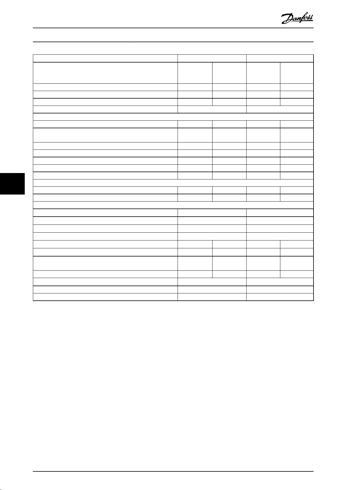
Specications
VLT® AutomationDrive FC 302
315–1200 kW
VLT® AutomationDrive FC 302
High/normal overload HO NO HO NO
(High overload=150% current during 60 s, normal overload=110%
current during 60 s)
Typical shaft output at 400 V [kW] 710 800 800 1000
Typical shaft output at 460 V [hp] 1000 1200 1200 1350
Typical shaft output at 500 V [kW] 800 1000 1000 1100
Enclosure size F12/F13 F12/F13
Output current (3-phase)
Continuous (at 400 V) [A] 1260 1460 1460 1720
Intermittent (60 s overload)
(at 400 V) [A]
Continuous (at 460/500 V) [A] 1160 1380 1380 1530
Intermittent (60 s overload)(at 460/500 V) [A] 1740 1518 2070 1683
Continuous kVA (at 400 V) [kVA] 873 1012 1012 1192
Continuous kVA (at 460 V) [kVA] 924 1100 1100 1219
Continuous kVA (at 500 V) [kVA] 1005 1195 1195 1325
77
Maximum input current
Continuous (at 400 V) [A] 1214 1407 1407 1658
Continuous (at 460/500 V) [A] 1118 1330 1330 1474
Maximum number and size of cables per phase
- Motor [mm2 (AWG)]
- Mains [mm2 (AWG)]
- Brake [mm2 (AWG)]
Maximum external mains fuses [A]
Estimated power loss at 400 V [W]
Estimated power loss at 460 V [W]
Maximum added losses A1 RFI, circuit breaker or disconnect, and
contactor [W], (F13 only)
Maximum panel options losses [W] 400 400 400 400
Eciency
Output frequency [Hz] 0–590 0–590
Control card overtemperature trip [°C (°F)]
3)
1)
2), 3)
2), 3)
14967 18084 16392 20358
13819 17137 15577 17752
P710 P800
1890 1606 2190 1892
12x150 (12x300 mcm) 12x150 (12x300 mcm)
6x120 (6x250 mcm) 6x120 (6x250 mcm)
6x185 (6x350 mcm) 6x185 (6x350 mcm)
1500 1500
2067 2280 2236 2541
0.98 0.98
85 (185) 85 (185)
Table 7.6 Electrical Data for Enclosures F12/F13, Mains Supply 6x380–500 V AC
1) For fuse ratings, see chapter 10.5 Fuses and Circuit Breakers.
±
2) Typical power loss is at normal conditions and expected to be within
values are based on a typical motor eciency (IE/IE3 border line). Lower eciency motors add to the power loss in the drive. Applies for
dimensioning of drive cooling. If the switching frequency is higher than the default setting, the power losses can increase. LCP and typical control
card power consumptions are included. For power loss data according to EN 50598-2, refer to drives.danfoss.com/knowledge-center/energy-
eciency-directive/#/. Options and customer load can add up to 30 W to the losses, though usually a fully loaded control card and options for
slots A and B each add only 4 W.
3) Measured using 5 m (16.5 ft) shielded motor cables at rated load and rated frequency. Eciency measured at nominal current. For energy
eciency class, see chapter 10.12 Eciency. For part load losses, see drives.danfoss.com/knowledge-center/energy-eciency-directive/#/.
44 Danfoss A/S © 11/2017 All rights reserved. MG34S302
15% (tolerance relates to variety in voltage and cable conditions). These
Page 47

Specications Design Guide
7.2 Electrical Data, 525–690 V
VLT® AutomationDrive FC 302
High/normal overload HO NO HO NO HO NO HO NO
(High overload=150% current during 60 s,
normal overload=110% current during 60 s)
Typical shaft output at 550 V [kW] 315 355 315 400 400 450 450 500
Typical shaft output at 575 V [hp] 400 450 400 500 500 600 600 650
Typical shaft output at 690 V [kW] 355 450 400 500 500 560 560 630
Enclosure size E1/E2 E1/E2 E1/E2 E1/E2
Output current (3-phase)
Continuous (at 550 V) [A] 395 470 429 523 523 596 596 630
Intermittent (60 s overload) (at 550 V) [A] 593 517 644 575 785 656 894 693
Continuous (at 575/690 V) [A] 380 450 410 500 500 570 570 630
Intermittent (60 s overload) (at 575/690 V) [A] 570 495 615 550 750 627 855 693
Continuous kVA (at 550 V) [kVA] 376 448 409 498 498 568 568 600
Continuous kVA (at 575 V) [kVA] 378 448 408 498 498 568 568 627
Continuous kVA (at 690 V) [kVA] 454 538 490 598 598 681 681 753
Maximum input current
Continuous (at 550 V) [A] 381 453 413 504 504 574 574 607
Continuous (at 575 V) [A] 366 434 395 482 482 549 549 607
Continuous (at 690 V) 366 434 395 482 482 549 549 607
Maximum number and size of
cables per phase
- Mains, motor, and load share [mm2 (AWG)]
- Brake [mm2 (AWG)]
Maximum external mains fuses [A]
Estimated power loss at 600 V [W]
Estimated power loss at 690 V [W]
Eciency
Output frequency [Hz] 0–500 0–500 0–500 0–500
Control card overtemperature trip [°C (°F)]
3)
1)
2), 3)
2), 3)
P355 P400 P500 P560
4x240 (4x500 mcm) 4x240 (4x500 mcm) 4x240 (4x500 mcm) 4x240 (4x500 mcm)
2x185 (2x350 mcm) 2x185 (2x350 mcm) 2x185 (2x350 mcm) 2x185 (2x350 mcm)
700 700 900 900
4424 5323 4795 6010 6493 7395 7383 8209
4589 5529 4970 6239 6707 7653 7633 8495
0.98 0.98 0.98 0.98
85 (185) 85 (185) 85 (185) 85 (185)
7 7
Table 7.7 Electrical Data for Enclosures E1/E2, Mains Supply 3x525–690 V AC
1) For fuse ratings, see chapter 10.5 Fuses and Circuit Breakers.
2) Typical power loss is at normal conditions and expected to be within ±15% (tolerance relates to variety in voltage and cable conditions). These
values are based on a typical motor eciency (IE/IE3 border line). Lower eciency motors add to the power loss in the drive. Applies for
dimensioning of drive cooling. If the switching frequency is higher than the default setting, the power losses can increase. LCP and typical control
card power consumptions are included. For power loss data according to EN 50598-2, refer to drives.danfoss.com/knowledge-center/energy-
eciency-directive/#/. Options and customer load can add up to 30 W to the losses, though usually a fully loaded control card and options for
slots A and B each add only 4 W.
3) Measured using 5 m (16.5 ft) shielded motor cables at rated load and rated frequency. Eciency measured at nominal current. For energy
eciency class, see chapter 10.12 Eciency. For part load losses, see drives.danfoss.com/knowledge-center/energy-eciency-directive/#/.
MG34S302 Danfoss A/S © 11/2017 All rights reserved. 45
Page 48

Specications
VLT® AutomationDrive FC 302
315–1200 kW
VLT® AutomationDrive FC 302
High/normal overload HO NO HO NO HO NO
(High overload=150% current during 60 s,
normal overload=110% current during 60 s)
Typical shaft output at 550 V [kW] 500 560 560 670 670 750
Typical shaft output at 575 V [hp] 650 750 750 950 950 1050
Typical shaft output at 690 V [kW] 630 710 710 800 800 900
Enclosure size F1/F3 F1/F3 F1/F3
Output current (3-phase)
Continuous (at 550 V) [A] 659 763 763 889 889 988
Intermittent (60 s overload) (at 550 V) [A] 989 839 1145 978 1334 1087
Continuous (at 575/690 V) [A] 630 730 730 850 850 945
Intermittent (60 s overload) (at 575/690 V) [A] 945 803 1095 935 1275 1040
Continuous kVA (at 550 V) [kVA] 628 727 727 847 847 941
Continuous kVA (at 575 V) [kVA] 627 727 727 847 847 941
Continuous kVA (at 690 V) [kVA] 753 872 872 1016 1016 1129
Maximum input current
77
Continuous (at 550 V) [A] 635 735 735 857 857 952
Continuous (at 575 V) [A] 607 704 704 819 819 911
Continuous (at 690 V) [A] 607 704 704 819 819 911
Maximum number and size of cables
per phase
- Motor [mm2 (AWG)]
- Mains [mm2 (AWG)] (F1)
- Mains [mm2 (AWG)] (F3)
- Load share [mm2 (AWG)]
- Brake [mm2 (AWG)]
Maximum external mains fuses [A]
Estimated power loss at 600 V [W]
Estimated power loss at 690 V [W]
Maximum added losses for circuit breaker or
disconnect and contactor [W], (F3 only)
Maximum panel options losses [W] 400 400 400 400 400 400
Eciency
Output frequency [Hz] 0–500 0–500 0–500
Control card overtemperature trip [°C (°F)]
3)
12)
2), 3)
2), 3)
P630 P710 P800
8x150 (8x300 mcm) 8x150 (8x300 mcm) 8x150 (8x300 mcm)
8x240 (8x500 mcm) 8x240 (8x500 mcm) 8x240 (8x500 mcm)
8x456 (4x900 mcm) 8x456 (4x900 mcm) 8x456 (4x900 mcm)
4x120 (4x250 mcm) 4x120 (4x250 mcm) 4x120 (4x250 mcm)
4x185 (4x350 mcm) 4x185 (4x350 mcm) 4x185 (4x350 mcm)
1600 1600 1600
8075 9500 9165 10872 10860 12316
8388 9863 9537 11304 11291 12798
342 427 419 532 519 615
0.98 0.98 0.98
85 (185) 85 (185) 85 (185)
Table 7.8 Electrical Data for Enclosures F1/F3, Mains Supply 3x525–690 V AC
1) For fuse ratings, see chapter 10.5 Fuses and Circuit Breakers.
2) Typical power loss is at normal conditions and expected to be within ±15% (tolerance relates to variety in voltage and cable conditions). These
values are based on a typical motor eciency (IE/IE3 border line). Lower eciency motors add to the power loss in the drive. Applies for
dimensioning of drive cooling. If the switching frequency is higher than the default setting, the power losses can increase. LCP and typical control
card power consumptions are included. For power loss data according to EN 50598-2, refer to drives.danfoss.com/knowledge-center/energy-
eciency-directive/#/. Options and customer load can add up to 30 W to the losses, though usually a fully loaded control card and options for
slots A and B each add only 4 W.
3) Measured using 5 m (16.5 ft) shielded motor cables at rated load and rated frequency. Eciency measured at nominal current. For energy
eciency class, see chapter 10.12 Eciency. For part load losses, see drives.danfoss.com/knowledge-center/energy-eciency-directive/#/.
46 Danfoss A/S © 11/2017 All rights reserved. MG34S302
Page 49

Specications Design Guide
VLT® AutomationDrive FC 302
High/normal overload HO NO HO NO HO NO
(High overload=150% current during 60 s,
normal overload=110% current during 60 s)
Typical shaft output at 550 V [kW] 750 850 850 1000 1000 1100
Typical shaft output at 575 V [hp] 1050 1150 1150 1350 1350 1550
Typical shaft output at 690 V [kW] 900 1000 1000 1200 1200 1400
Enclosure size F2/F4 F2/F4 F2/F4
Output current (3-phase)
Continuous (at 550 V) [A] 988 1108 1108 1317 1317 1479
Intermittent (60 s overload) (at 550 V) [A] 1482 1219 1662 1449 1976 1627
Continuous (at 575/690 V) [A] 945 1060 1060 1260 1260 1415
Intermittent (60 s overload) (at 575/690 V) [A] 1418 1166 1590 1386 1890 1557
Continuous kVA (at 550 V) [kVA] 941 1056 1056 1255 1255 1409
Continuous kVA (at 575 V) [kVA] 941 1056 1056 1255 1255 1409
Continuous kVA (at 690 V) [kVA] 1129 1267 1267 1506 1506 1691
Maximum input current
Continuous (at 550 V) [A] 952 1068 1068 1269 1269 1425
Continuous (at 575 V) [A] 911 1022 1022 1214 1214 1364
Continuous (at 690 V) [A] 911 1022 1022 1214 1214 1364
Maximum number and size of cables
per phase
- Motor [mm2 (AWG)]
- Mains [mm2 (AWG)] (F2)
- Mains [mm2 (AWG)] (F4)
- Load share [mm2 (AWG)]
- Brake [mm2 (AWG)]
Maximum external mains fuses [A]
Estimated power loss at 600 V [W]
Estimated power loss at 690 V [W]
Maximum added losses for circuit breaker or
disconnect and contactor [W], (F4 only)
Maximum panel options losses [W] 400 400 400 400 400 400
Eciency
Output frequency [Hz] 0–500 0–500 0–500
Control card overtemperature trip [°C (°F)]
3)
1)
2), 3)
2), 3)
P900 P1M0 P1M2
12x150 (12x300 mcm) 12x150 (12x300 mcm) 12x150 (12x300 mcm)
8x240 (8x500 mcm) 8x240 (8x500 mcm) 8x240 (8x500 mcm)
8x456 (8x900 mcm) 8x456 (8x900 mcm) 8x456 (8x900 mcm)
4x120 (4x250 mcm) 4x120 (4x250 mcm) 4x120 (4x250 mcm)
6x185 (6x350 mcm) 6x185 (6x350 mcm) 6x185 (6x350 mcm)
1600 2000 2500
12062 13731 13269 16190 16089 18536
12524 14250 13801 16821 16719 19247
556 665 634 863 861 1044
0.98 0.98 0.98
85 (185) 85 (185) 85 (185)
7 7
Table 7.9 Electrical Data for Enclosures F2/F4, Mains Supply 3x525–690 V AC
1) For fuse ratings, see chapter 10.5 Fuses and Circuit Breakers.
2) Typical power loss is at normal conditions and expected to be within ±15% (tolerance relates to variety in voltage and cable conditions). These
values are based on a typical motor eciency (IE/IE3 border line). Lower eciency motors add to the power loss in the drive. Applies for
dimensioning of drive cooling. If the switching frequency is higher than the default setting, the power losses can increase. LCP and typical control
card power consumptions are included. For power loss data according to EN 50598-2, refer to drives.danfoss.com/knowledge-center/energy-
eciency-directive/#/. Options and customer load can add up to 30 W to the losses, though usually a fully loaded control card and options for
slots A and B each add only 4 W.
3) Measured using 5 m (16.5 ft) shielded motor cables at rated load and rated frequency. Eciency measured at nominal current. For energy
eciency class, see chapter 10.12 Eciency. For part load losses, see drives.danfoss.com/knowledge-center/energy-eciency-directive/#/.
MG34S302 Danfoss A/S © 11/2017 All rights reserved. 47
Page 50

Specications
VLT® AutomationDrive FC 302
315–1200 kW
VLT® AutomationDrive FC 302
High/normal overload HO NO HO NO HO NO HO NO
(High overload=150% current during 60 s,
normal overload=110% current during 60 s)
Typical shaft output at 550 V [kW] 315 355 315 400 400 450 450 500
Typical shaft output at 575 V [hp] 400 450 400 500 500 600 600 650
Typical shaft output at 690 V [kW] 355 450 400 500 500 560 560 630
Enclosure size F8/F9 F8/F9 F8/F9 F8/F9
Output current (3-phase)
Continuous (at 550 V) [A] 395 470 429 523 523 596 596 630
Intermittent (60 s overload) (at 550 V) [A] 593 517 644 575 785 656 894 693
Continuous (at 575/690 V) [A] 380 450 410 500 500 570 570 630
Intermittent (60 s overload) (at 575/690 V) [A] 570 495 615 550 750 627 855 693
Continuous kVA (at 550 V) [kVA] 376 448 409 498 498 568 568 600
Continuous kVA (at 575 V) [kVA] 378 448 408 498 498 568 568 627
Continuous kVA (at 690 V) [kVA] 454 538 490 598 598 681 681 753
Maximum input current
77
Continuous (at 550 V) [A] 381 453 413 504 504 574 574 607
Continuous (at 575 V) [A] 366 434 395 482 482 549 549 607
Continuous (at 690 V) 366 434 395 482 482 549 549 607
Maximum number and size of
cables per phase
- Motor [mm2 (AWG)]
- Mains [mm2 (AWG)]
- Brake [mm2 (AWG)]
Maximum external mains fuses [A]
Estimated power loss at 600 V [W]
Estimated power loss at 690 V [W]
Eciency
Output frequency [Hz] 0–500 0–500 0–500 0–500
Control card overtemperature trip [°C (°F)]
3)
1)
2), 3)
2), 3)
P355 P400 P500 P560
4x240 (4x500 mcm) 4x240 (4x500 mcm) 4x240 (4x500 mcm) 4x240 (4x500 mcm)
4x85 (4x3/0 mcm) 4x85 (4x3/0 mcm) 4x85 (4x3/0 mcm) 4x85 (4x3/0 mcm)
2x185 (2x350 mcm) 2x185 (2x350 mcm) 2x185 (2x350 mcm) 2x185 (2x350 mcm)
630 630 630 630
4424 5323 4795 6010 6493 7395 7383 8209
4589 5529 4970 6239 6707 7653 7633 8495
0.98 0.98 0.98 0.98
85 (185) 85 (185) 85 (185) 85 (185)
Table 7.10 Electrical Data for Enclosures F8/F9, Mains Supply 6x525–690 V AC
1) For fuse ratings, see chapter 10.5 Fuses and Circuit Breakers.
±
2) Typical power loss is at normal conditions and expected to be within
values are based on a typical motor eciency (IE/IE3 border line). Lower eciency motors add to the power loss in the drive. Applies for
dimensioning of drive cooling. If the switching frequency is higher than the default setting, the power losses can increase. LCP and typical control
card power consumptions are included. For power loss data according to EN 50598-2, refer to drives.danfoss.com/knowledge-center/energy-
eciency-directive/#/. Options and customer load can add up to 30 W to the losses, though usually a fully loaded control card and options for
slots A and B each add only 4 W.
3) Measured using 5 m (16.5 ft) shielded motor cables at rated load and rated frequency. Eciency measured at nominal current. For energy
eciency class, see chapter 10.12 Eciency. For part load losses, see drives.danfoss.com/knowledge-center/energy-eciency-directive/#/.
15% (tolerance relates to variety in voltage and cable conditions). These
48 Danfoss A/S © 11/2017 All rights reserved. MG34S302
Page 51

Specications Design Guide
VLT® AutomationDrive FC 302
High/normal overload HO NO HO NO HO NO
(High overload=150% current during 60 s,
normal overload=110% current during 60 s)
Typical shaft output at 550 V [kW] 500 560 560 670 670 750
Typical shaft output at 575 V [hp] 650 750 750 950 950 1050
Typical shaft output at 690 V [kW] 630 710 710 800 800 900
Enclosure size F10/F11 F10/F11 F10/F11
Output current (3-phase)
Continuous (at 550 V) [A] 659 763 763 889 889 988
Intermittent (60 s overload) (at 550 V) [A] 989 839 1145 978 1334 1087
Continuous (at 575/690 V) [A] 630 730 730 850 850 945
Intermittent (60 s overload) (at 575/690 V) [A] 945 803 1095 935 1275 1040
Continuous kVA (at 550 V) [kVA] 628 727 727 847 847 941
Continuous kVA (at 575 V) [kVA] 627 727 727 847 847 941
Continuous kVA (at 690 V) [kVA] 753 872 872 1016 1016 1129
Maximum input current
Continuous (at 550 V) [A] 635 735 735 857 857 952
Continuous (at 575 V) [A] 607 704 704 819 819 911
Continuous (at 690 V) [A] 607 704 704 819 819 911
Maximum number and size of cables
per phase
- Motor [mm2 (AWG)]
- Mains [mm2 (AWG)]
- Brake [mm2 (AWG)]
Maximum external mains fuses [A]
Estimated power loss at 600 V [W]
Estimated power loss at 690 V [W]
Maximum added losses for circuit breaker or
disconnect and contactor [W], (F11 only)
Maximum panel options losses [W] 400 400 400 400 400 400
Eciency
Output frequency [Hz] 0–500 0–500 0–500
Control card overtemperature trip [°C (°F)]
3)
1)
2), 3)
2), 3)
P630 P710 P800
8x150 (8x300 mcm) 8x150 (8x300 mcm) 8x150 (8x300 mcm)
6x120 (4x900 mcm) 6x120 (4x900 mcm) 6x120 (4x900 mcm)
4x185 (4x350 mcm) 4x185 (4x350 mcm) 4x185 (4x350 mcm)
900 900 900
8075 9500 9165 10872 10860 12316
8388 9863 9537 11304 11291 12798
342 427 419 532 519 615
0.98 0.98 0.98
85 (185) 85 (185) 85 (185)
7 7
Table 7.11 Electrical Data for Enclosures F10/F11, Mains Supply 6x525–690 V AC
1) For fuse ratings, see chapter 10.5 Fuses and Circuit Breakers.
±
2) Typical power loss is at normal conditions and expected to be within
values are based on a typical motor eciency (IE/IE3 border line). Lower eciency motors add to the power loss in the drive. Applies for
dimensioning of drive cooling. If the switching frequency is higher than the default setting, the power losses can increase. LCP and typical control
card power consumptions are included. For power loss data according to EN 50598-2, refer to drives.danfoss.com/knowledge-center/energy-
eciency-directive/#/. Options and customer load can add up to 30 W to the losses, though usually a fully loaded control card and options for
slots A and B each add only 4 W.
3) Measured using 5 m (16.5 ft) shielded motor cables at rated load and rated frequency. Eciency measured at nominal current. For energy
eciency class, see chapter 10.12 Eciency. For part load losses, see drives.danfoss.com/knowledge-center/energy-eciency-directive/#/.
MG34S302 Danfoss A/S © 11/2017 All rights reserved. 49
15% (tolerance relates to variety in voltage and cable conditions). These
Page 52

Specications
VLT® AutomationDrive FC 302
315–1200 kW
VLT® AutomationDrive FC 302
High/normal overload HO NO HO NO HO NO
(High overload=150% current during 60 s,
normal overload=110% current during 60 s)
Typical shaft output at 550 V [kW] 750 850 850 1000 1000 1100
Typical shaft output at 575 V [hp] 1050 1150 1150 1350 1350 1550
Typical shaft output at 690 V [kW] 900 1000 1000 1200 1200 1400
Enclosure size F12/F13 F12/F13 F12/F13
Output current (3-phase)
Continuous (at 550 V) [A] 988 1108 1108 1317 1317 1479
Intermittent (60 s overload) (at 550 V) [A] 1482 1219 1219 1449 1976 1627
Continuous (at 575/690 V) [A] 945 1060 1060 1260 1260 1415
Intermittent (60 s overload) (at 575/690 V) [A] 1418 1166 1590 1386 1890 1557
Continuous kVA (at 550 V) [kVA] 941 1056 1056 1255 1255 1409
Continuous kVA (at 575 V) [kVA] 941 1056 1056 1255 1255 1409
Continuous kVA (at 690 V) [kVA] 1129 1267 1267 1506 1506 1691
Maximum input current
77
Continuous (at 550 V) [A] 952 1068 1068 1269 1269 1425
Continuous (at 575 V) [A] 911 1022 1022 1214 1214 1364
Continuous (at 690 V) [A] 911 1022 1022 1214 1214 1364
Maximum number and size of cables
per phase
- Motor [mm2 (AWG)]
- Mains [mm2 (AWG)] (F12)
- Mains [mm2 (AWG)] (F13)
- Brake [mm2 (AWG)]
Maximum external mains fuses [A]
Estimated power loss at 600 V [W]
Estimated power loss at 690 V [W]
Maximum added losses for circuit breaker or
disconnect and contactor [W], (F13 only)
Maximum panel options losses [W] 400 400 400 400 400 400
Eciency
Output frequency [Hz] 0–500 0–500 0–500
Control card overtemperature trip [°C (°F)]
3)
1)
2), 3)
2), 3)
P900 P1M0 P1M2
12x150 (12x300 mcm) 12x150 (12x300 mcm) 12x150 (12x300 mcm)
8x240 (8x500 mcm) 8x240 (8x500 mcm) 8x240 (8x500 mcm)
8x456 (8x900 mcm) 8x456 (8x900 mcm) 8x456 (8x900 mcm)
6x185 (6x350 mcm) 6x185 (6x350 mcm) 6x185 (6x350 mcm)
1600 2000 2500
12062 13731 13269 16190 16089 18536
12524 14250 13801 16821 16719 19247
556 665 634 863 861 1044
0.98 0.98 0.98
85 (185) 85 (185) 85 (185)
Table 7.12 Electrical Data for Enclosures F12/F13, Mains Supply 6x525–690 V AC
1) For fuse ratings, see chapter 10.5 Fuses and Circuit Breakers.
±
2) Typical power loss is at normal conditions and expected to be within
values are based on a typical motor eciency (IE/IE3 border line). Lower eciency motors add to the power loss in the drive. Applies for
dimensioning of drive cooling. If the switching frequency is higher than the default setting, the power losses can increase. LCP and typical control
card power consumptions are included. For power loss data according to EN 50598-2, refer to drives.danfoss.com/knowledge-center/energy-
eciency-directive/#/. Options and customer load can add up to 30 W to the losses, though usually a fully loaded control card and options for
slots A and B each add only 4 W.
3) Measured using 5 m (16.5 ft) shielded motor cables at rated load and rated frequency. Eciency measured at nominal current. For energy
eciency class, see chapter 10.12 Eciency. For part load losses, see drives.danfoss.com/knowledge-center/energy-eciency-directive/#/.
50 Danfoss A/S © 11/2017 All rights reserved. MG34S302
15% (tolerance relates to variety in voltage and cable conditions). These
Page 53

Specications Design Guide
7.3 Mains Supply
Mains supply
Supply terminals (6-pulse) L1, L2, L3
Supply terminals (12-pulse) L1-1, L2-1, L3-1, L1-2, L2-2, L3-2
Supply voltage 380–480 V ±10%, 525–690 V ±10%
Mains voltage low/mains voltage drop-out:
During low mains voltage or a mains drop-out, the drive continues until the DC-link voltage drops below the minimum stop
level, which corresponds typically to 15% below the lowest rated supply voltage of the drive. Power-up and full torque cannot be
expected at mains voltage lower than 10% below the lowest rated supply voltage of the drive.
Supply frequency 50/60 Hz ±5%
Maximum imbalance temporary between mains phases 3.0% of rated supply voltage
True power factor (λ) ≥0.9 nominal at rated load
Displacement power factor (cos Φ) near unity (>0.98)
Switching on input supply L1, L2, L3 (power ups) Maximum 1 time/2 minute
Environment according to EN60664-1 Overvoltage category III/pollution degree 2
The drive is suitable for use on a circuit capable of delivering up to 100 kA short-circuit current rating (SCCR) at 480/600 V.
1) Calculations based on UL/IEC61800-3.
7.4 Motor Output and Motor Data
1)
7 7
Motor output (U, V, W)
Output voltage 0–100% of supply voltage
Output frequency 0–590 Hz
Output frequency in ux mode 0–300 Hz
Switching on output Unlimited
Ramp times 0.01–3600 s
1) Dependent on voltage and power.
Torque characteristics
Starting torque (constant torque) Maximum 150% for 60 s
Overload torque (constant torque) Maximum 150% for 60 s
1) Percentage relates to the nominal current of the drive.
2) Once every 10 minutes.
1), 2)
1), 2)
7.5 Ambient Conditions
Environment
E1/F1/F2/F3/F4/F8/F9/F10/F11/F12/F13 enclosures IP21/Type 1, IP54/Type 12
E2 enclosure IP00/Chassis
Vibration test 1.0 g
Relative humidity 5–95% (IEC 721-3-3; Class 3K3 (non-condensing) during operation)
Aggressive environment (IEC 60068-2-43) H2S test Class Kd
Aggressive gases (IEC 60721-3-3) Class 3C3
Test method according to IEC 60068-2-43 H2S (10 days)
Ambient temperature (at SFAVM switching mode)
- with derating Maximum 55 °C (131 °F)
- with full output power of typical EFF2 motors (up to 90% output current) Maximum 50 °C (122 °F)
- at full continuous FC output current Maximum 45 °C (113 °F)
Minimum ambient temperature during full-scale operation 0 °C (32 °F)
Minimum ambient temperature at reduced performance -10 °C (14 °F)
Temperature during storage/transport -25 to +65/70 °C (13 to 149/158 °F)
Maximum altitude above sea level without derating 1000 m (3281 ft)
1)
1)
1)
1)
MG34S302 Danfoss A/S © 11/2017 All rights reserved. 51
Page 54

Specications
Maximum altitude above sea level with derating 3000 m (9842 ft)
1) For more information on derating, see chapter 9.6 Derating.
EMC standards, Emission EN 61800-3
EMC standards, Immunity EN 61800-3
Energy eciency class
1) Determined according to EN 50598-2 at:
Rated load.
•
90% rated frequency.
•
Switching frequency factory setting.
•
Switching pattern factory setting.
•
1)
VLT® AutomationDrive FC 302
315–1200 kW
IE2
7.6 Cable Specications
Cable lengths and cross-sections for control cables
Maximum motor cable length, shielded 150 m (492 ft)
77
Maximum motor cable length, unshielded 300 m (984 ft)
Maximum cross-section to motor, mains, load sharing, and brake See chapter 7 Specications
Maximum cross-section to control terminals, rigid wire 1.5 mm2/16 AWG (2x0.75 mm2)
Maximum cross-section to control terminals, exible cable 1 mm2/18 AWG
Maximum cross-section to control terminals, cable with enclosed core 0.5 mm2/20 AWG
Minimum cross-section to control terminals 0.25 mm2/23 AWG
1) For power cables, see electrical data in chapter 7.1 Electrical Data, 380–500 V and chapter 7.2 Electrical Data, 525–690 V.
1)
7.7 Control Input/Output and Control Data
Digital inputs
Programmable digital inputs 4 (6)
Terminal number 18, 19, 271), 291), 32, 33
Logic PNP or NPN
Voltage level 0–24 V DC
Voltage level, logic 0 PNP <5 V DC
Voltage level, logic 1 PNP >10 V DC
Voltage level, logic 0 NPN >19 V DC
Voltage level, logic 1 NPN <14 V DC
Maximum voltage on input 28 V DC
Input resistance, R
All digital inputs are galvanically isolated from the supply voltage (PELV) and other high-voltage terminals.
1) Terminals 27 and 29 can also be programmed as outputs.
Analog inputs
Number of analog inputs 2
Terminal number 53, 54
Modes Voltage or current
Mode select Switches A53 and A54
Voltage mode Switch A53/A54=(U)
Voltage level -10 V to +10 V (scaleable)
Input resistance, R
Maximum voltage ±20 V
Current mode Switch A53/A54=(I)
Current level 0/4 to 20 mA (scaleable)
Input resistance, R
Maximum current 30 mA
Resolution for analog inputs 10 bit (+ sign)
Accuracy of analog inputs Maximum error 0.5% of full scale
i
i
i
Approximately 4 kΩ
Approximately 10 kΩ
Approximately 200 Ω
52 Danfoss A/S © 11/2017 All rights reserved. MG34S302
Page 55

Mains
Functional
isolation
PELV isolation
Motor
DC-bus
High
voltage
Control
+24 V
RS485
18
37
130BA117.10
Specications Design Guide
Bandwidth 100 Hz
The analog inputs are galvanically isolated from the supply voltage (PELV) and other high-voltage terminals.
Illustration 7.1 PELV Isolation
Pulse inputs
Programmable pulse inputs 2
Terminal number pulse 29, 33
Maximum frequency at terminal 29, 33 (push-pull driven) 110 kHz
Maximum frequency at terminal 29, 33 (open collector) 5 kHz
Minimum frequency at terminal 29, 33 4 Hz
Voltage level See Digital Inputs in chapter 7.7 Control Input/Output and Control Data
Maximum voltage on input 28 V DC
Input resistance, R
i
Approximately 4 kΩ
Pulse input accuracy (0.1–1 kHz) Maximum error: 0.1% of full scale
7 7
Analog output
Number of programmable analog outputs 1
Terminal number 42
Current range at analog output 0/4–20 mA
Maximum resistor load to common at analog output 500 Ω
Accuracy on analog output Maximum error: 0.8% of full scale
Resolution on analog output 8 bit
The analog output is galvanically isolated from the supply voltage (PELV) and other high-voltage terminals.
Control card, RS485 serial communication
Terminal number 68 (P, TX+, RX+), 69 (N, TX-, RX-)
Terminal number 61 Common for terminals 68 and 69
The RS485 serial communication circuit is functionally separated from other central circuits and galvanically isolated from the
supply voltage (PELV).
Digital output
Programmable digital/pulse outputs 2
Terminal number 27, 29
Voltage level at digital/frequency output 0–24 V
Maximum output current (sink or source) 40 mA
Maximum load at frequency output 1 kΩ
Maximum capacitive load at frequency output 10 nF
Minimum output frequency at frequency output 0 Hz
Maximum output frequency at frequency output 32 kHz
Accuracy of frequency output Maximum error: 0.1% of full scale
Resolution of frequency outputs 12 bit
1) Terminals 27 and 29 can also be programmed as inputs.
The digital output is galvanically isolated from the supply voltage (PELV) and other high-voltage terminals.
1)
MG34S302 Danfoss A/S © 11/2017 All rights reserved. 53
Page 56

Specications
Control card, 24 V DC output
Terminal number 12, 13
Maximum load 200 mA
The 24 V DC supply is galvanically isolated from the supply voltage (PELV), but has the same potential as the analog and digital
inputs and outputs.
Relay outputs
Programmable relay outputs 2
Maximum cross-section to relay terminals 2.5 mm2 (12 AWG)
Minimum cross-section to relay terminals 0.2 mm2 (30 AWG)
Length of stripped wire 8 mm (0.3 in)
Relay 01 terminal number 1–3 (break), 1–2 (make)
Maximum terminal load (AC-1)1) on 1–2 (NO) (Resistive load)
Maximum terminal load (AC-15)1) on 1–2 (NO) (Inductive load @ cosφ 0.4) 240 V AC, 0.2 A
Maximum terminal load (DC-1)1) on 1–2 (NO) (Resistive load) 80 V DC, 2 A
Maximum terminal load (DC-13)1) on 1–2 (NO) (Inductive load) 24 V DC, 0.1 A
Maximum terminal load (AC-1)1) on 1–3 (NC) (Resistive load) 240 V AC, 2 A
77
Maximum terminal load (AC-15)1) on 1–3 (NC) (Inductive load @ cosφ 0.4) 240 V AC, 0.2 A
Maximum terminal load (DC-1)1) on 1–3 (NC) (Resistive load) 50 V DC, 2 A
Maximum terminal load (DC-13)1) on 1–3 (NC) (Inductive load) 24 V DC, 0.1 A
Minimum terminal load on 1–3 (NC), 1–2 (NO) 24 V DC 10 mA, 24 V AC 2 mA
Environment according to EN 60664-1 Overvoltage category III/pollution degree 2
Relay 02 terminal number 4–6 (break), 4–5 (make)
Maximum terminal load (AC-1)1) on 4–5 (NO) (Resistive load)
Maximum terminal load (AC-15)1) on 4–5 (NO) (Inductive load @ cosφ 0.4) 240 V AC, 0.2 A
Maximum terminal load (DC-1)1) on 4–5 (NO) (Resistive load) 80 V DC, 2 A
Maximum terminal load (DC-13)1) on 4–5 (NO) (Inductive load) 24 V DC, 0.1 A
Maximum terminal load (AC-1)1) on 4–6 (NC) (Resistive load) 240 V AC, 2 A
Maximum terminal load (AC-15)1) on 4–6 (NC) (Inductive load @ cosφ 0.4) 240 V AC, 0.2 A
Maximum terminal load (DC-1)1) on 4–6 (NC) (Resistive load) 50 V DC, 2 A
Maximum terminal load (DC-13)1) on 4–6 (NC) (Inductive load) 24 V DC, 0.1 A
Minimum terminal load on 4–6 (NC), 4–5 (NO) 24 V DC 10 mA, 24 V AC 2 mA
Environment according to EN 60664-1 Overvoltage category III/pollution degree 2
The relay contacts are galvanically isolated from the rest of the circuit by reinforced isolation (PELV).
1) IEC 60947 part 4 and 5.
2) Overvoltage Category II.
3) UL applications 300 V AC 2 A.
VLT® AutomationDrive FC 302
315–1200 kW
2), 3)
2), 3)
400 V AC, 2 A
400 V AC, 2 A
Control card, +10 V DC output
Terminal number 50
Output voltage 10.5 V ±0.5 V
Maximum load 25 mA
The 10 V DC supply is galvanically isolated from the supply voltage (PELV) and other high-voltage terminals.
Control characteristics
Resolution of output frequency at 0–1000 Hz ±0.003 Hz
System response time (terminals 18, 19, 27, 29, 32, 33) ≤2 m/s
Speed control range (open loop) 1:100 of synchronous speed
Speed accuracy (open loop) 30–4000 RPM: Maximum error of ±8 RPM
All control characteristics are based on a 4-pole asynchronous motor.
Control card performance
Scan interval 5 M/S
54 Danfoss A/S © 11/2017 All rights reserved. MG34S302
Page 57

Specications Design Guide
Control card, USB serial communication
USB standard 1.1 (full speed)
USB plug USB type B device plug
NOTICE
Connection to PC is carried out via a standard host/device USB cable.
The USB connection is galvanically isolated from the supply voltage (PELV) and other high-voltage terminals.
The USB connection is not galvanically isolated from ground. Use only isolated laptop/PC as connection to the USB
connector on the drive or an isolated USB cable/converter.
7.8 Enclosure Weights
Enclosure 380–480/500 V 525–690 V
E1 270–313 kg (595–690 lb) 263–313 kg (580–690 lb)
E2 234–277 kg (516–611 lb) 221–277 kg (487–611 lb)
Table 7.13 Enclosure E1–E2 Weights, kg (lb)
Enclosure 380–480/500 V 525–690 V
F1 1017 kg (2242.1 lb) 1017 kg (2242.1 lb)
F2 1260 kg (2777.9 lb) 1260 kg (2777.9 lb)
F3 1318 kg (2905.7 lb) 1318 kg (2905.7 lb)
F4 1561 kg (3441.5 lb) 1561 kg (3441.5 lb)
F8 447 kg (985.5 lb) 447 kg (985.5 lb)
F9 669 kg (1474.9 lb) 669 kg (1474.9 lb)
F10 893 kg (1968.8 lb) 893 kg (1968.8 lb)
F11 1116 kg (2460.4 lb) 1116 kg (2460.4 lb)
F12 1037 kg (2286.4 lb) 1037 kg (2286.4 lb)
F13 1259 kg (2775.7 lb) 1259 kg (2775.7 lb)
Table 7.14 Enclosure F1–F13 Weights, kg (lb)
7 7
MG34S302 Danfoss A/S © 11/2017 All rights reserved. 55
Page 58

e30bg051.10
1
2
e30bg052.10
1 2
Specications
VLT® AutomationDrive FC 302
315–1200 kW
7.9 Airow for Enclosures E1–E2 and F1–F13
77
1
Front channel airow, 340 m3/hr (200 cfm)
2 Back-channel airow,
1105 m3/hr (650 cfm) or 1444 m3/hr (850 cfm)
Illustration 7.2 Airow for Enclosure E1
1
Front channel airow, 255 m3/hr (150 cfm)
2 Back-channel airow,
1105 m3/hr (650 cfm) or 1444 m3/hr (850 cfm)
Illustration 7.3 Airow for Enclosure E2
56 Danfoss A/S © 11/2017 All rights reserved. MG34S302
Page 59

e30bg053.10
1
2
Specications Design Guide
7 7
1 Front channel airow
- IP21/Type 1, 700 m3/hr (412 cfm)
- IP54/Type 12, 525 m3/hr (309 cfm)
2
Back-channel airow, 985 m3/hr (580 cfm)
Illustration 7.4 Airow for Enclosure F1–13
MG34S302 Danfoss A/S © 11/2017 All rights reserved. 57
Page 60

130BF328.10
600 (23.6)
2000
(78.7)
538 (21.2)
494 (19.4)
579
(22.8)
748
(29.5)
Exterior and Terminal Dimen...
VLT® AutomationDrive FC 302
315–1200 kW
8 Exterior and Terminal Dimensions
8.1 E1 Exterior and Terminal Dimensions
8.1.1 E1 Exterior Dimensions
88
Illustration 8.1 Front, Side, and Door Clearance Dimensions for E1
58 Danfoss A/S © 11/2017 All rights reserved. MG34S302
Page 61

130BF611.10
2
1
35 (1.4)
350 (13.8)
203 (8.0)
99 (3.9)
130 (5.1)
62 (2.4)
104 (4.1)
35 (1.4)
10 (0.4)
0 (0.0)
0 (0.0)
40 (1.6)
78 (3.1)
0 (0.0)
26 (1.0)
26 (1.0)
130BF647.10
Exterior and Terminal Dimen... Design Guide
8 8
1 Mains side 2 Motor side
Illustration 8.2 Gland Plate Dimensions for E1/E2
8.1.2 E1 Terminal Dimensions
Power cables are heavy and hard to bend. To ensure easy installation of the cables, consider the optimum placement of the
drive. Each terminal allows up to 4 cables with cable lugs or a standard box lug. Ground is connected to a relevant
termination point in the drive.
Illustration 8.3 Detailed Terminal Dimensions for E1/E2
MG34S302 Danfoss A/S © 11/2017 All rights reserved. 59
Page 62

130BF595.10
195 (7.7)
0.0
323 (12.7)
492 (19.4)
75 (3.0)
0.0
188 (7.4)
300 (11.8)
412 (16.2)
525 (20.7)
600 (23.6)
546 (21.5)
510 (20.1)
462 (18.2)
426 (16.8)
453 (17.8)
1
2
3
4
Exterior and Terminal Dimen...
VLT® AutomationDrive FC 302
315–1200 kW
88
1 Mains terminals 3 Regen/load share terminals
2 Brake terminals 4 Motor terminals
Illustration 8.4 Terminal Dimensions for E1, Front View
60 Danfoss A/S © 11/2017 All rights reserved. MG34S302
Page 63

130BF596.10
154 (6.1)
0.0
192 (7.6)
280 (11.0)
371 (14.6)
409 (16.1)
1
2
3
Exterior and Terminal Dimen... Design Guide
8 8
1 Mains terminals 2 Brake terminals
3 Motor terminals – –
Illustration 8.5 Terminal Dimensions for E1, Side View
MG34S302 Danfoss A/S © 11/2017 All rights reserved. 61
Page 64

130BF597.10
562 (22.1)
253 (9.9)
342 (13.5)
431 (17.0)
0.0
0.0
1
Exterior and Terminal Dimen...
VLT® AutomationDrive FC 302
315–1200 kW
88
1 Mains terminals – –
Illustration 8.6 Terminal Dimensions for E1 with Disconnect (380–480/500 V Models: P315; 525–690 V Models: P355–P560), Front View
62 Danfoss A/S © 11/2017 All rights reserved. MG34S302
Page 65

130BF598.10
0.0
51 (2.0)
226 (8.9)
266 (10.5)
441 (17.4)
0.0
28 (1.1)
167 (6.6)
195 (7.7)
381 (15.0)
1
Exterior and Terminal Dimen... Design Guide
8 8
1 Mains terminals – –
Illustration 8.7 Terminal Dimensions for E1 with Disconnect (380–480/500 V Models: P315; 525–690 V Models: P355–P560), Side View
MG34S302 Danfoss A/S © 11/2017 All rights reserved. 63
Page 66

416 (16.4)
455 (17.9)
251 (9.9)
341 (13.4)
431 (17.0)
0.0
0.0
130BF599.10
1
Exterior and Terminal Dimen...
VLT® AutomationDrive FC 302
315–1200 kW
88
1 Mains terminals – –
Illustration 8.8 Terminal Dimensions for E1 with Disconnect (380–480/500 V Models: P355–P400), Front View
64 Danfoss A/S © 11/2017 All rights reserved. MG34S302
Page 67

130BF600.10
0.0
51 (2.0)
226 (8.9)
266 (10.5)
441 (17.4)
0.0
28 (1.1)
167 (6.6)
195 (7.7)
371 (14.6)
1
Exterior and Terminal Dimen... Design Guide
8 8
1 Mains terminals – –
Illustration 8.9 Terminal Dimensions for E1 with Disconnect (380–480/500 V Models: P355–P400), Side View
MG34S302 Danfoss A/S © 11/2017 All rights reserved. 65
Page 68

130BF329.10
585 (23.0)
1547
(60.9)
538
(21.2)
498 (19.5)
Exterior and Terminal Dimen...
VLT® AutomationDrive FC 302
315–1200 kW
8.2 E2 Exterior and Terminal Dimensions
8.2.1 E2 Exterior Dimensions
88
Illustration 8.10 Front, Side, and Door Clearance Dimensions for E2
66 Danfoss A/S © 11/2017 All rights reserved. MG34S302
Page 69

130BF611.10
2
1
35 (1.4)
350 (13.8)
203 (8.0)
99 (3.9)
130 (5.1)
62 (2.4)
104 (4.1)
35 (1.4)
10 (0.4)
0 (0.0)
0 (0.0)
40 (1.6)
78 (3.1)
0 (0.0)
26 (1.0)
26 (1.0)
130BF647.10
Exterior and Terminal Dimen... Design Guide
8 8
1 Mains side 2 Motor side
Illustration 8.11 Gland Plate Dimensions for E1/E2
8.2.2 E2 Terminal Dimensions
Power cables are heavy and hard to bend. To ensure easy installation of the cables, consider the optimum placement of the
drive. Each terminal allows up to 4 cables with cable lugs or a standard box lug. Ground is connected to a relevant
termination point in the drive.
Illustration 8.12 Detailed Terminal Dimensions for E1/E2
MG34S302 Danfoss A/S © 11/2017 All rights reserved. 67
Page 70

130BF601.10
R/L1 91
9
S/L2 92
U/T1 96 V/T2 97
T/L3 93
W/T3 98
F ASTENER T OR QUE M8 9.6 N m (7 FT -LB) F ASTENER T OR QUE M8 9.6 N m (7 FT -LB)
186 (7.3)
17 (0.7)
585 (23.0)
518 (20.4)
405 (15.9)
293 (11.5)
181 (7.1)
68 (2.7)
0.0
0.0
147 (5.8)
583(22.9)
502 (19.8)
454 (17.9)
418 (16.4)
1
3
2
4
Exterior and Terminal Dimen...
VLT® AutomationDrive FC 302
315–1200 kW
88
1 Mains terminals 3 Motor terminals
2 Brake terminals 4 Regen/load share terminals
Illustration 8.13 Terminal Dimensions for E2, Front View
68 Danfoss A/S © 11/2017 All rights reserved. MG34S302
Page 71

409 (16.1)
371 (14.6)
280 (11.0)
192 (7.6)
154 (6.1)
0.0
130BF602.10
1
2
3
Exterior and Terminal Dimen... Design Guide
1 Mains terminals 2 Brake terminals
3 Motor terminals – –
Illustration 8.14 Terminal Dimensions for E2, Side View
8 8
MG34S302 Danfoss A/S © 11/2017 All rights reserved. 69
Page 72

256 (10.1)
0.0
245 (9.6)
0.0
334 (13.1)
423 (16.7)
130BF603.10
1
Exterior and Terminal Dimen...
VLT® AutomationDrive FC 302
315–1200 kW
88
1 Mains terminals – –
Illustration 8.15 Terminal Dimensions for E2 with Disconnect (380–480/500 V Models: P315; 525–690 V Models: P355–P560), Front
View
70 Danfoss A/S © 11/2017 All rights reserved. MG34S302
Page 73

381 (15.0)
0.0
130BF604.10
1
Exterior and Terminal Dimen... Design Guide
1 Mains terminals – –
Illustration 8.16 Terminal Dimensions for E2 with Disconnect (380–480/500 V Models: P315; 525–690 V Models: P355–P560), Side
View
8 8
MG34S302 Danfoss A/S © 11/2017 All rights reserved. 71
Page 74

256 (10.1)
0.0
149 (5.8)
245 (9.6)
0.0
334 (13.1)
423 (16.7)
130BF605.10
1
Exterior and Terminal Dimen...
VLT® AutomationDrive FC 302
315–1200 kW
88
1 Mains terminals – –
Illustration 8.17 Terminal Dimensions for E2 with Disconnect (380–480/500 V Models: P355–P400), Front View
72 Danfoss A/S © 11/2017 All rights reserved. MG34S302
Page 75

381 (15.0)
0.0
130BF606.10
1
Exterior and Terminal Dimen... Design Guide
1 Mains terminals – –
Illustration 8.18 Terminal Dimensions for E2 with Disconnect (380–480/500 V Models: P355–P400), Side View
8 8
MG34S302 Danfoss A/S © 11/2017 All rights reserved. 73
Page 76

130BF375.10
2280
(89.7)
2204
(86.8)
1400 (55.2)
606
(23.9)
578
(22.8)
776
(30.6)
Exterior and Terminal Dimen...
VLT® AutomationDrive FC 302
315–1200 kW
8.3 F1 Exterior and Terminal Dimensions
8.3.1 F1 Exterior Dimensions
88
Illustration 8.19 Front, Side, and Door Clearance Dimensions for F1
74 Danfoss A/S © 11/2017 All rights reserved. MG34S302
Page 77

130BF612.10
216 (8.6)
668 (26.3)
38 (1.5)
593 (23.3)
460 (18.1)
535 (21.1)
282 (11.1)
36 (1.4)
1
533 (21.0)
596 (23.4)
1329 (52.3)
200 (7.9)
258 (10.2)
36 (1.4)
Exterior and Terminal Dimen... Design Guide
1 Mains side 2 Motor side
Illustration 8.20 Gland Plate Dimensions for F1
8 8
MG34S302 Danfoss A/S © 11/2017 All rights reserved. 75
Page 78

130BF583.10
2
1
CH22
Exterior and Terminal Dimen...
VLT® AutomationDrive FC 302
315–1200 kW
8.3.2 F1 Terminal Dimensions
Power cables are heavy and hard to bend. To ensure easy installation of the cables, consider the optimum placement of the
drive. Each terminal allows up to 4 cables with cable lugs or a standard box lug. Ground is connected to a relevant
termination point in the drive.
88
1 Mains terminals 2 Ground bar
Illustration 8.21 Terminal Dimensions for F1–F4 Rectier Cabinet, Front View
76 Danfoss A/S © 11/2017 All rights reserved. MG34S302
Page 79

0.0
130BF584.10
70 (2.8)
194 (7.6)
343 (13.5)
38 (1.5)
0.0
90 (3.6)
137 (5.4)
189 (7.4)
432 (17.0)
380 (15.0)
436 (17.2)
2
3
1
Exterior and Terminal Dimen... Design Guide
1 Mains terminals 3 Load share terminals (–)
2 Load share terminals (+) – –
Illustration 8.22 Terminal Dimensions for F1–F2 Rectier Cabinet, Side View
8 8
MG34S302 Danfoss A/S © 11/2017 All rights reserved. 77
Page 80

130BF373.10
54 (2.1)
169 (6.7)
284 (11.2)
407 (16.0)
522 (20.6)
637 (25.1)
198 (7.8)
234 (9.2)
282 (11.1)
318 (12.5)
551 (21.7)
587 (23.1)
635 (25.0)
671 (26.4)
204.1 (8.0)
497. (19.6)
572 (22.5)
129.1 (5.1)
0.0
3
2
1
Exterior and Terminal Dimen...
VLT® AutomationDrive FC 302
315–1200 kW
88
1 Brake terminals 3 Ground bar
2 Motor terminals – –
Illustration 8.23 Terminal Dimensions for F1/F3 Inverter Cabinet, Front View
78 Danfoss A/S © 11/2017 All rights reserved. MG34S302
Page 81

130BF374.10
287 (11.3)
253 (10.0)
0.0
0.0
339 (13.4)
308 (12.1)
466 (18.3)
44 (1.8)
244 (9.6)
180 (7.1)
287 (11.3)
0.0
339 (13.4)
466 (18.3)
1
2
3
Exterior and Terminal Dimen... Design Guide
1 Brake terminals 3 Ground bar
2 Motor terminals – –
Illustration 8.24 Terminal Dimensions for F1/F3 Inverter Cabinet, Side View
8 8
MG34S302 Danfoss A/S © 11/2017 All rights reserved. 79
Page 82
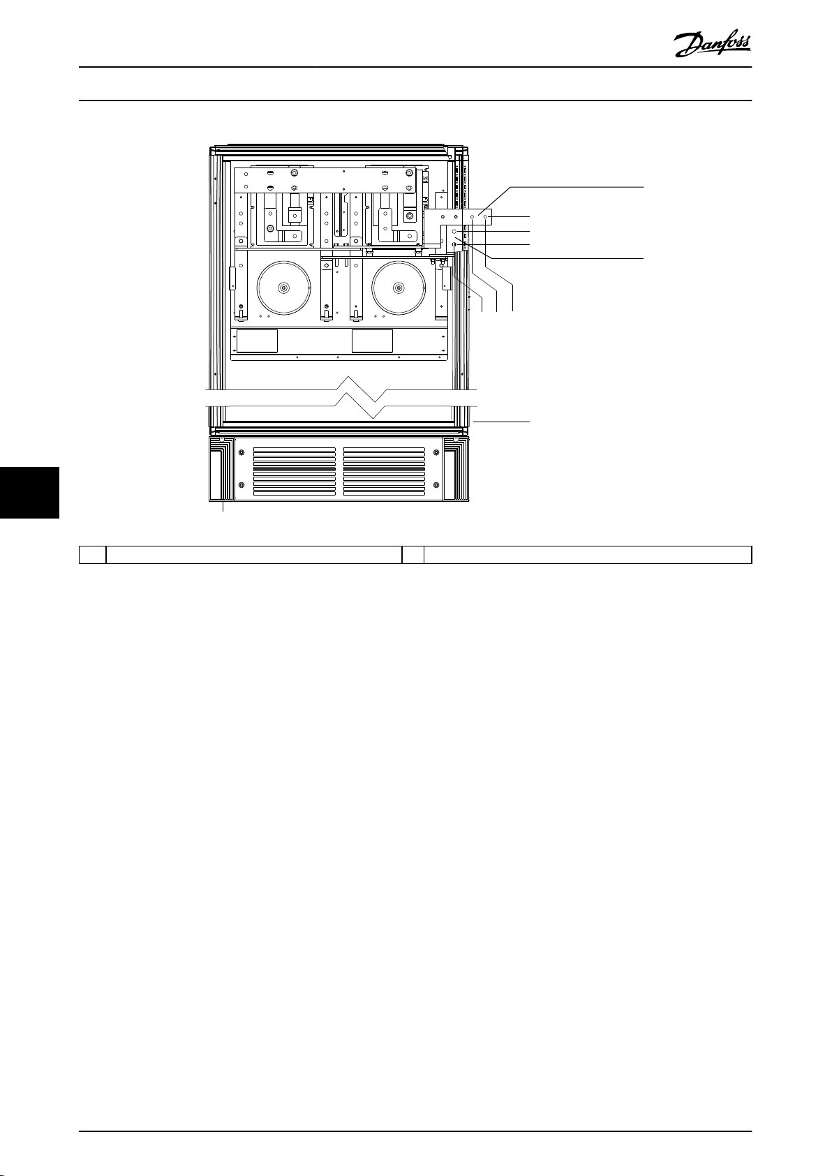
1739 (68.5)
0.0
805 (31.7)
0.0
765 (30.1)
710 (28.0)
1694 (66.7)
1654 (65.1)
130BF365.10
1
2
Exterior and Terminal Dimen...
VLT® AutomationDrive FC 302
315–1200 kW
88
1 DC – 2 DC +
Illustration 8.25 Terminal Dimensions for F1/F3 Regeneration Terminals, Front View
80 Danfoss A/S © 11/2017 All rights reserved. MG34S302
Page 83

130BF330.11
2280
(89.7)
2204
(86.8)
1800 (70.9)
606
(23.9)
579
(22.8)
578
(22.8)
624
(24.6)
Exterior and Terminal Dimen... Design Guide
8.4 F2 Exterior and Terminal Dimensions
8.4.1 F2 Exterior Dimensions
8 8
Illustration 8.26 Front, Side, and Door Clearance Dimensions for F2
MG34S302 Danfoss A/S © 11/2017 All rights reserved. 81
Page 84

533 (21.0)
594 (23.4)
1728 (68.0)
36 (1.4)
258 (10.2)
200 (7.9)
38 (1.5) 460 (18.1)
994 (39.1)
216 (8.5)
36 (1.4)
282 (11.1)
1
130BF613.10
535 (21.1)
656 (25.8)
Exterior and Terminal Dimen...
VLT® AutomationDrive FC 302
315–1200 kW
88
1 Mains side 2 Motor side
Illustration 8.27 Gland Plate Dimensions for F2
82 Danfoss A/S © 11/2017 All rights reserved. MG34S302
Page 85

130BF583.10
2
1
CH22
Exterior and Terminal Dimen... Design Guide
8.4.2 F2 Terminal Dimensions
Power cables are heavy and hard to bend. To ensure easy installation of the cables, consider the optimum placement of the
drive. Each terminal allows up to 4 cables with cable lugs or a standard box lug. Ground is connected to a relevant
termination point in the drive.
8 8
1 Mains terminals 2 Ground bar
Illustration 8.28 Terminal Dimensions for F1–F4 Rectier Cabinet, Front View
MG34S302 Danfoss A/S © 11/2017 All rights reserved. 83
Page 86

0.0
130BF584.10
70 (2.8)
194 (7.6)
343 (13.5)
38 (1.5)
0.0
90 (3.6)
137 (5.4)
189 (7.4)
432 (17.0)
380 (15.0)
436 (17.2)
2
3
1
Exterior and Terminal Dimen...
VLT® AutomationDrive FC 302
315–1200 kW
88
1 Mains terminals 3 Load share terminals (–)
2 Load share terminals (+) – –
Illustration 8.29 Terminal Dimensions for F1–F2 Rectier Cabinet, Side View
84 Danfoss A/S © 11/2017 All rights reserved. MG34S302
Page 87

210 (8.3)
0.0
66 (2.6)
181 (7.1)
296 (11.7)
431 (17.0)
546 (21.5)
661 (26.0)
796 (31.3)
911 (35.8)
1026 (40.4)
246 (9.7)
294 (11.6)
330 (13.0)
575 (22.6)
611 (24.0)
659 (25.9)
695 (27.4)
939 (37.0)
975 (38.4)
1023 (40.3)
1059 (41.7)
144 (5.7)
219 (8.6)
512 (20.2)
587 (23.1)
880 (34.7)
955 (37.6)
3
130BF363.10
1
2
Exterior and Terminal Dimen... Design Guide
1 Brake terminals 3 Ground bar
2 Motor terminals – –
Illustration 8.30 Terminal Dimensions for F2/F4 Inverter Cabinet, Front View
8 8
MG34S302 Danfoss A/S © 11/2017 All rights reserved. 85
Page 88

130BF364.10
287 (11.3)
339 (13.4)
253 (10.0)
0.0
287 (11.3)
0.0
339 (13.4)
466 (18.3)
466 (18.3)
308 (12.1)
180 (7.1)
0.0
1
2
3
Exterior and Terminal Dimen...
VLT® AutomationDrive FC 302
315–1200 kW
88
1 Brake terminals 3 Ground bar
2 Motor terminals – –
Illustration 8.31 Terminal Dimensions for F2/F4 Inverter Cabinet, Side View
86 Danfoss A/S © 11/2017 All rights reserved. MG34S302
Page 89

130BF366.10
1
2
1203 (47.4)
0.0
1163 (45.8)
1098 (43.2)
1739 (68.4)
1694 (66.7)
1654 (65.1)
0.0
Exterior and Terminal Dimen... Design Guide
1 DC – 2 DC +
Illustration 8.32 Terminal Dimensions for F2/F4 Regeneration Terminals, Front View
8 8
MG34S302 Danfoss A/S © 11/2017 All rights reserved. 87
Page 90

130BF376.10
2280
(89.7)
2204
(86.8)
2000 (78.8)
606
(23.9)
578
(22.8)
578
(22.8)
776
(30.6)
Exterior and Terminal Dimen...
VLT® AutomationDrive FC 302
315–1200 kW
8.5 F3 Exterior and Terminal Dimensions
8.5.1 F3 Exterior Dimensions
88
Illustration 8.33 Front, Side, and Door Clearance Dimensions for F3
88 Danfoss A/S © 11/2017 All rights reserved. MG34S302
Page 91

1265 (49.8) 593 (23.3)
130BF614.10
38 (1.5)
200 (7.9)
259 (10.2)
1
635 (25.0)
535 (21.1)
533 (21.0)
597 (23.5)
1130 (44.5)
1193 (47.0)
1926 (75.8)
36 (1.4)
36 (1.4)
2x 460 (18.1)
2x 216 (8.5)
2x 281 (11.1)
Exterior and Terminal Dimen... Design Guide
1 Mains side 2 Motor side
Illustration 8.34 Gland Plate Dimensions for F3
8 8
MG34S302 Danfoss A/S © 11/2017 All rights reserved. 89
Page 92

2
295 (11.6)
220 (18.6)
0.0
130BF586.10
154 (6.1)
150 (5.9)
75 (3.0)
439 (17.3)
364 (14.3)
344 (13.5)
1
Exterior and Terminal Dimen...
VLT® AutomationDrive FC 302
315–1200 kW
8.5.2 F3 Terminal Dimensions
Power cables are heavy and hard to bend. To ensure easy installation of the cables, consider the optimum placement of the
drive. Each terminal allows up to 4 cables with cable lugs or a standard box lug. Ground is connected to a relevant
termination point in the drive.
88
1 Mains terminals 2 Ground bar
Illustration 8.35 Terminal Dimensions for F3–F4 Options Cabinet, Front View
90 Danfoss A/S © 11/2017 All rights reserved. MG34S302
Page 93

0.0
244 (9.6)
44 (1.8)
939 (37.0)
1031 (40.6)
0.0
135 (5.3)
0.0
130BF587.10
171 (6.7)
119 (4.7)
128 (5.0)
76 (3.0)
1
2
Exterior and Terminal Dimen... Design Guide
1 Mains terminals 2 Ground bar
Illustration 8.36 Terminal Dimensions for F3–F4 Options Cabinet, Side View
8 8
MG34S302 Danfoss A/S © 11/2017 All rights reserved. 91
Page 94

104 (4.1)
0.0
179 (7.0)
220 (8.7)
295 (11.6)
335 (13.2)
410 (16.1)
154 (6.1)
344 (13.5)
2
130BF588.10
1
Exterior and Terminal Dimen...
VLT® AutomationDrive FC 302
315–1200 kW
88
1 Mains terminals 2 Ground bar
Illustration 8.37 Terminal Dimensions for F3–F4 Options Cabinet with Circuit Breaker/Molded Case Switch, Front View
92 Danfoss A/S © 11/2017 All rights reserved. MG34S302
Page 95

130BF589.10
0.0
35 (1.4)
87 (3.4)
122 (4.8)
174 (6.8)
0.0
135 (5.3)
437 (17.2)
0.0
533 (21.0)
44 (1.7)
244 (9.6)
1
2
Exterior and Terminal Dimen... Design Guide
1 Mains terminals 2 Ground bar
Illustration 8.38 Terminal Dimensions for F3–F4 Options Cabinet with Circuit Breaker/Molded Case Switch (380–480/500 V Models:
P450; 525–690 V Models: P630–P710), Side View
8 8
MG34S302 Danfoss A/S © 11/2017 All rights reserved. 93
Page 96

130BF644.10
0.0
46 (1.8)
98 (3.9)
119 (4.7)
171 (6.7)
0.0
135 (5.3)
437 (17.2)
0.0
533 (21.0)
44 (1.7)
244 (9.6)
1
2
Exterior and Terminal Dimen...
VLT® AutomationDrive FC 302
315–1200 kW
88
1 Mains terminals 2 Ground bar
Illustration 8.39 Terminal Dimensions for F3–F4 Options Cabinet with Circuit Breaker/Molded Case Switch (380–480/500 V Models:
P500–P630; 525–690 V Models: P800), Side View
94 Danfoss A/S © 11/2017 All rights reserved. MG34S302
Page 97

130BF583.10
2
1
CH22
Exterior and Terminal Dimen... Design Guide
1 Mains terminals 2 Ground bar
Illustration 8.40 Terminal Dimensions for F1–F4 Rectier Cabinet, Front View
8 8
MG34S302 Danfoss A/S © 11/2017 All rights reserved. 95
Page 98

130BF585.10
0.0
70 (2.8)
194 (7.6)
343 (13.5)
38 (1.5)
0.0
90 (3.6)
137 (5.4)
189 (7.4)
81 (3.2)
29 (1.2)
436 (17.2)
3
2
1
Exterior and Terminal Dimen...
VLT® AutomationDrive FC 302
315–1200 kW
88
1 Mains terminals 3 Load share terminals (–)
2 Load share terminals (+) – –
Illustration 8.41 Terminal Dimensions for F3–F4 Rectier Cabinet, Side View
96 Danfoss A/S © 11/2017 All rights reserved. MG34S302
Page 99

130BF373.10
54 (2.1)
169 (6.7)
284 (11.2)
407 (16.0)
522 (20.6)
637 (25.1)
198 (7.8)
234 (9.2)
282 (11.1)
318 (12.5)
551 (21.7)
587 (23.1)
635 (25.0)
671 (26.4)
204.1 (8.0)
497. (19.6)
572 (22.5)
129.1 (5.1)
0.0
3
2
1
Exterior and Terminal Dimen... Design Guide
1 Brake terminals 3 Ground bar
2 Motor terminals – –
Illustration 8.42 Terminal Dimensions for F1/F3 Inverter Cabinet, Front View
8 8
MG34S302 Danfoss A/S © 11/2017 All rights reserved. 97
Page 100

130BF374.10
287 (11.3)
253 (10.0)
0.0
0.0
339 (13.4)
308 (12.1)
466 (18.3)
44 (1.8)
244 (9.6)
180 (7.1)
287 (11.3)
0.0
339 (13.4)
466 (18.3)
1
2
3
Exterior and Terminal Dimen...
VLT® AutomationDrive FC 302
315–1200 kW
88
1 Brake terminals 3 Ground bar
2 Motor terminals – –
Illustration 8.43 Terminal Dimensions for F1/F3 Inverter Cabinet, Side View
98 Danfoss A/S © 11/2017 All rights reserved. MG34S302
 Loading...