

Page 1
MAKING MODERN LIVING POSSIBLE
Operating Instructions
VLT® AutomationDrive FC 302 Low Harmonic Drive
132-630 kW
vlt-drives.danfoss.com
Page 2

Page 3
Page 4
Page 5

Contents Operating Instructions
Contents
1 Introduction
1.1 Purpose of the Manual
1.2 Additional Resources
1.3 Product Overview
1.3.1 Intended Use 5
1.3.2 Working Principle 6
1.3.3 Exploded View Drawings 7
1.4 Enclosure Sizes and Power Ratings
1.5 Approvals and Certications
1.5.1 Approvals 15
1.5.2 Compliance with ADN 15
1.6 Harmonics Overview
1.6.1 Harmonics 15
1.6.2 Harmonic Analysis 15
1.6.3 Eect of Harmonics in a Power Distribution System 16
1.6.4 IEC Harmonic Standards 17
1.6.5 IEEE Harmonic Standards 18
5
5
5
5
15
15
15
2 Safety
2.1 Safety
2.2 Qualied Personnel
2.3 Safety Precautions
3 Mechanical Installation
3.1 Installation Site Checklist
3.2 Unpacking
3.2.1 Items Supplied 22
3.3 Mounting
3.3.1 Cooling and Airow 23
3.3.2 Lifting 24
3.3.3 Cable Entry and Anchoring 26
3.3.4 Terminal Locations for Enclosure Size D1n/D2n 30
3.3.5 Terminal Locations for Enclosure Size E9 32
3.3.6 Terminal Locations for Enclsoure Size F18 33
3.3.7 Torque 35
20
20
20
20
21
21
22
23
4 Electrical Installation
4.1 Safety Instructions
4.2 Electromagnetic Compatability (EMC)
4.2.1 EMC Interference 37
MG37A302 Danfoss A/S © Rev. 04/2015 All rights reserved. 1
36
36
37
Page 6

Contents
VLT® AutomationDrive FC 302 Low Harmonic Drive
132-630 kW
4.3 Power Connections
4.4 Grounding
4.5 Input Options
4.5.1 Extra Protection (RCD) 39
4.5.2 RFI Switch 39
4.5.3 Screened Cables 39
4.6 Motor Connection
4.6.1 Motor Cable 39
4.6.2 Brake Cable 40
4.6.3 Motor Insulation 40
4.6.4 Motor Bearing Currents 41
4.7 AC Mains Connection
4.7.1 Mains Connection 41
4.7.2 External Fan Supply 41
4.7.3 Power and Control Wiring for Unscreened Cables 42
4.7.4 Mains Disconnects 42
4.7.5 F-FrameCircuit Breakers 43
38
38
39
39
41
4.7.6 F-Frame Mains Contactors 43
4.8 Control Wiring
4.8.1 Control Cable Routing 43
4.8.2 Access to Control Terminals 45
4.8.3 Electrical Installation, Control Terminals 45
4.8.4 Electrical Installation, Control Cables 47
4.8.5 Safe Torque O (STO) 49
4.9 Additional Connections
4.9.1 Serial Communication 49
4.9.2 Mechanical Brake Control 49
4.9.3 Parallel Connection of Motors 50
4.9.4 Motor Thermal Protection 50
4.9.5 Voltage/Current Input Selection (Switches) 50
4.10 Final Set-up and Test
4.11 F-frame Options
5 Commissioning
5.1 Safety Instructions
43
49
51
52
54
54
5.2 Applying Power
5.3 Local Control Panel Operation
5.3.1 Local Control Panel 56
5.3.2 LCP Layout 56
5.3.3 Parameter Settings 57
5.3.4 Uploading/Downloading Data to/from the LCP 58
2 Danfoss A/S © Rev. 04/2015 All rights reserved. MG37A302
56
56
Page 7

Contents Operating Instructions
5.3.5 Changing Parameter Settings 58
5.3.6 Restoring Default Settings 58
5.4 Basic Operational Programming
5.4.1 VLT® Low Harmonic Drive Programming 59
5.4.2 Commissioning with SmartStart 59
5.4.3 Commissioning via [Main Menu] 59
5.4.4 Asynchronous Motor Set-up 60
5.4.5 Permanent Magnet Motor Set-up 60
5.4.6 Automatic Energy Optimisation (AEO) 61
5.4.7 Automatic Motor Adaptation (AMA) 62
5.5 Checking Motor Rotation
5.6 Local Control Test
5.7 System Start-up
6 Application Examples
6.1 Introduction
6.2 Application Examples
7 Diagnostics and Troubleshooting
7.1 Status Messages
59
62
62
62
63
63
63
68
68
7.2 Warning and Alarm Types
7.2.1 Warnings 68
7.2.2 Alarm Trip 68
7.2.3 Alarm Trip-lock 68
7.3 Warnings and Alarm Denitions - Frequency Converter
7.4 Warnings and Alarm Denitions - Active Filter
7.5 Troubleshooting
8 Specications
8.1 Power-Dependent Specications
8.1.1 Mains Supply 3x380–480 V AC 85
8.1.2 Derating for Temperature 88
8.2 Mechanical Dimensions
8.3 General Technical Data
8.4 Fuses
8.4.1 Non-UL Compliance 99
8.4.2 Fuse Tables 99
8.4.3 Supplementary Fuses 100
68
68
77
82
85
85
90
93
98
8.5 General Torque Tightening Values
9 Appendix A - Parameters
9.1 Description of Parameters
MG37A302 Danfoss A/S © Rev. 04/2015 All rights reserved. 3
101
102
102
Page 8

Contents
VLT® AutomationDrive FC 302 Low Harmonic Drive
132-630 kW
9.2 Frequency Converter Parameter Lists
9.3 Active Filter Parameter Lists
10 Appendix B
10.1 Abbreviations and Conventions
Index
102
108
115
115
116
4 Danfoss A/S © Rev. 04/2015 All rights reserved. MG37A302
Page 9

Introduction Operating Instructions
1 Introduction
1
1
1.1 Purpose of the Manual
The purpose of this manual is to provide information for
the installation and operation of a VLT® AutomationDrive
FC 302 Low Harmonic Drive. The manual includes relevant
safety information for installation and operation.
Chapter 1 Introduction, chapter 2 Safety,
chapter 3 Mechanical Installation, and chapter 4 Electrical
Installation introduce the unit functions and cover proper
mechanical and electrical installation procedures. There are
chapters on start-up and commissioning, applications and
basic troubleshooting. Chapter 8 Specications provides a
quick reference for ratings and dimensions, as well as other
operating specications. This manual provides a basic
knowledge of the unit and explains set-up and basic
operation.
VLT® is a registered trademark.
1.2 Additional Resources
Other resources are available to understand advanced
functions and programming.
The VLT® AutomationDrive FC 302 Programming
•
Guide provides greater detail on working with
parameters and many application examples.
®
The VLT
•
provides detailed capabilities and functionality to
design motor control systems.
Supplemental publications and manuals are
•
available from Danfoss.
See vlt-drives.danfoss.com/Support/Technical-
Documentation/ for listings.
Optional equipment may change some of the
•
procedures described. Reference the instructions
supplied with those options for specic
requirements. Contact the local Danfoss supplier
or visit the Danfoss website: vlt-
drives.danfoss.com/Support/TechnicalDocumentation/ for downloads or additional
information.
The VLT
•
Instructions provide additional information about
the lter portion of the low harmonic drive.
AutomationDrive FC 302 Design Guide
®
Active Filter AAF 006 Operating
1.3
Product Overview
1.3.1 Intended Use
A frequency converter is an electronic motor controller
that converts AC mains input into a variable AC waveform
output. The frequency and voltage of the output are
regulated to control the motor speed or torque. The
frequency converter can vary the speed of the motor in
response to system feedback, such as with position sensors
on a conveyor belt. The frequency converter can also
regulate the motor by responding to remote commands
from external controllers.
The frequency converter:
Monitors the system and motor status.
•
Issues warnings or alarms for fault conditions.
•
Starts and stops the motor.
•
Optimises energy eciency.
•
Operation and monitoring functions are available as status
indications to an outside control system or serial communication network.
A low harmonic drive (LHD) is a single unit that combines
the frequency converter with an advanced active lter
(AAF) for harmonic mitigation. The frequency converter
and lter are packaged together in an integrated system,
but each functions independently. In this manual, there are
separate specications for the frequency converter and the
lter. Since the frequency converter and lter are in the
same enclosure, the unit is transported, installed, and
operated as a single entity.
MG37A302 Danfoss A/S © Rev. 04/2015 All rights reserved. 5
Page 10
Mains
380 to
500 VAC
Optional
RFI
Optional
Fuses
Optional
Manual
Disconnect
HI Reactor
L
m
L
m
L
m
L
ac
L
ac
L
ac
AC
Contactor
Relay 12
Control & AUX
Feedback
Soft-Charge
Resistor
Converter Side
Filter
Power Stage
AF Current
Sensors
Capacitor
Current Sensors
VLT Drive
Main’s
3
3
3
CTs
L
c
L
c
L
c
CefC
ef
C
ef
R
ef
R
ef
R
ef
I
r
I
s
I
t
130BB406.11
Introduction
VLT® AutomationDrive FC 302 Low Harmonic Drive
132-630 kW
1
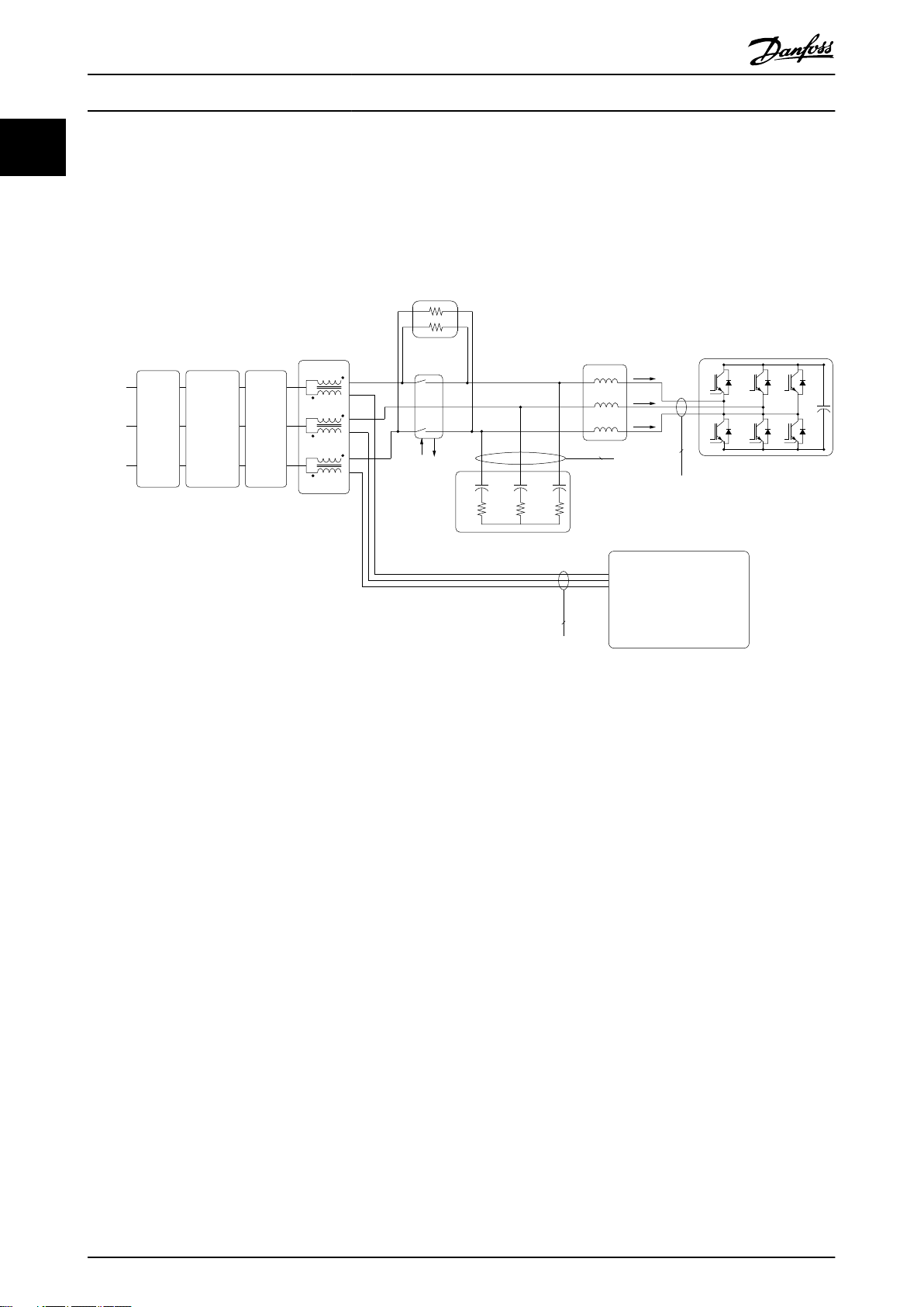
1.3.2 Working Principle
The low harmonic drive is a high-power frequency converter with an integrated active lter. An active lter is a device that
actively monitors harmonic distortion levels and injects compensative harmonic current onto the line to cancel the
harmonics.
Illustration 1.1 Basic Layout for the Low Harmonic Drive
Low harmonic drives are designed to draw an ideal sinusoidal current waveform from the supply grid with a power factor of
1. Where traditional non-linear load draws pulse-shaped currents, the low harmonic drive compensates that via the parallel
lter path, lowering the stress on the supply grid. The low harmonic drive meets the highest harmonic standards with a
THDi less than 5% at full load for <3% pre-distortion on a 3% unbalanced 3-phase grid.
6 Danfoss A/S © Rev. 04/2015 All rights reserved. MG37A302
Page 11
130BE136.10
1
2
3
4
5
6
7
8
6
Introduction
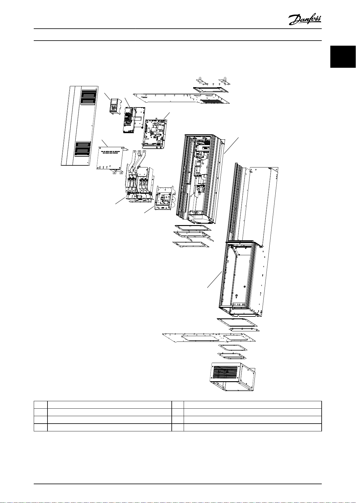
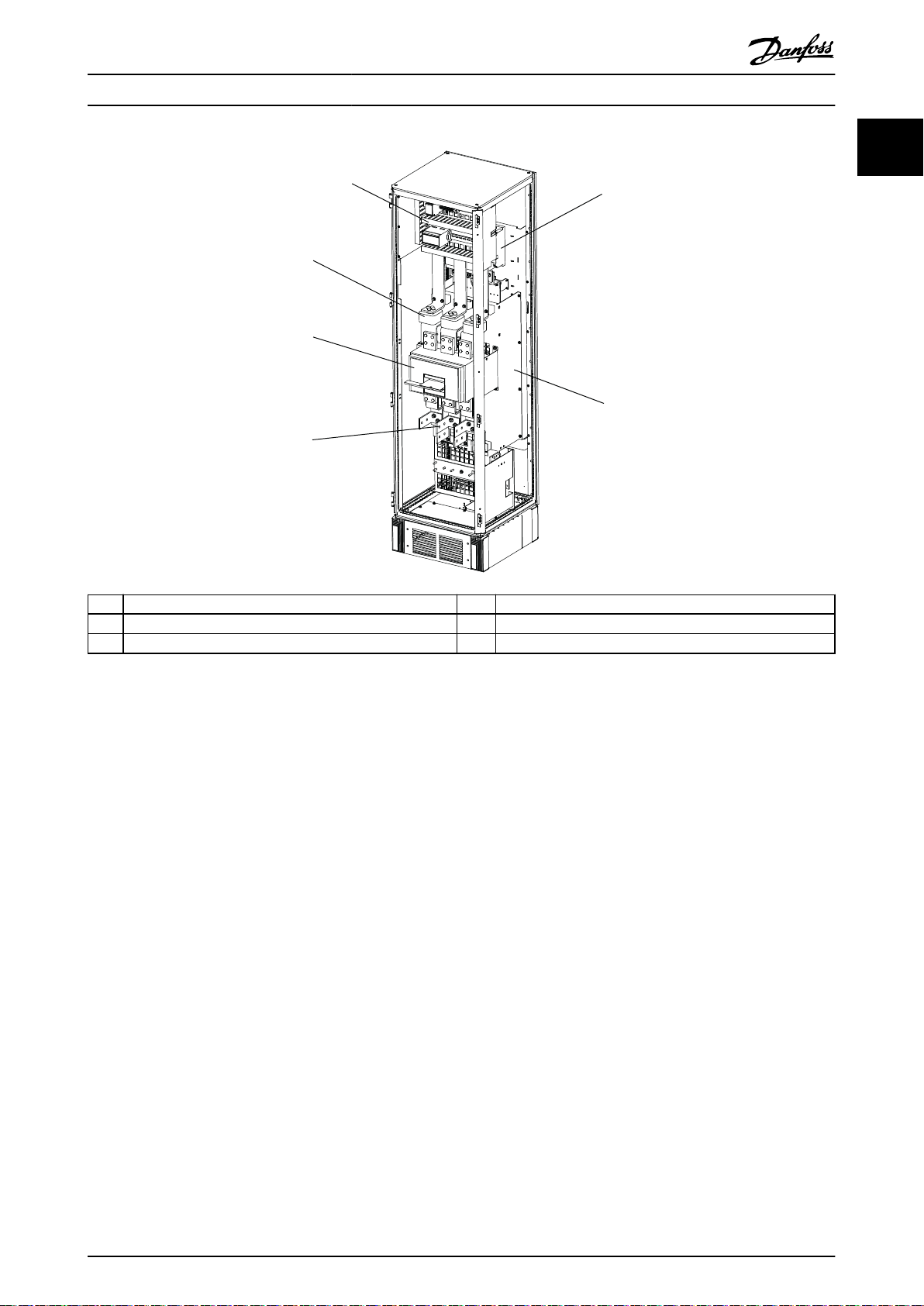
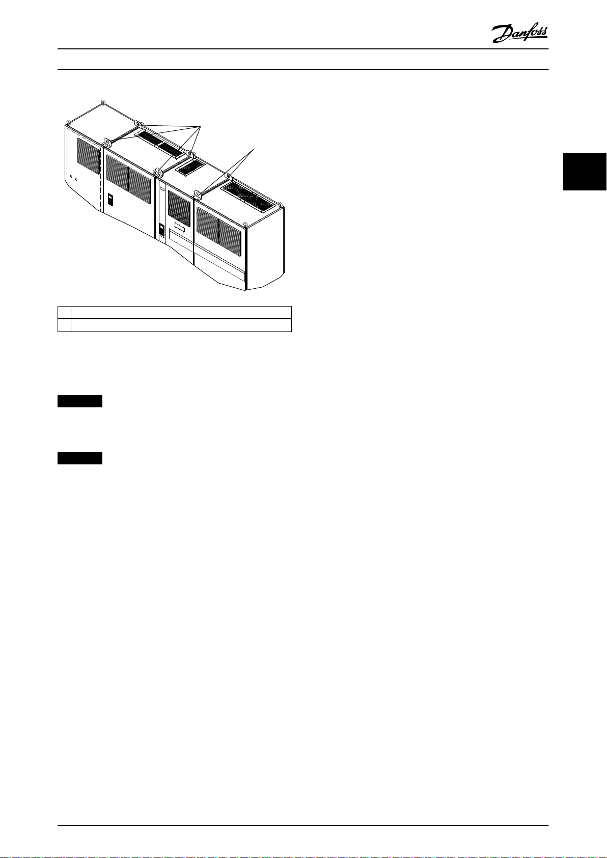
1.3.3 Exploded View Drawings
Operating Instructions
1
1
1 Local control panel (LCP) 5 Input/output terminal assembly
2 Control card assembly 6 Capacitor bank assembly
3 Power card assembly 7 D1/D2 assembly
4 Terminal cover sheet 8 EOC assembly
Illustration 1.2 Enclosure Size D1n/D2n, Frequency Converter Enclosure
MG37A302 Danfoss A/S © Rev. 04/2015 All rights reserved. 7
Page 12
7
4
5
8
9
1
2
3
6
20
22
19
18
16
23
15
21
17
10
11
12
13
14
130BE110.10
1
Introduction
VLT® AutomationDrive FC 302 Low Harmonic Drive
132-630 kW
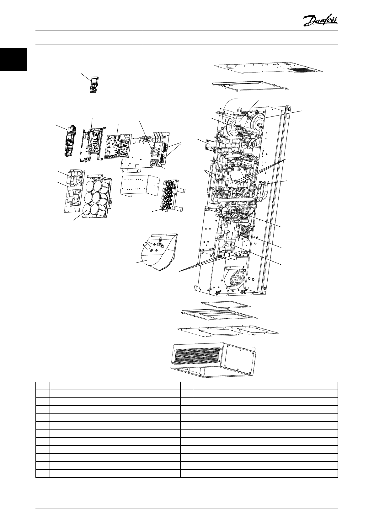
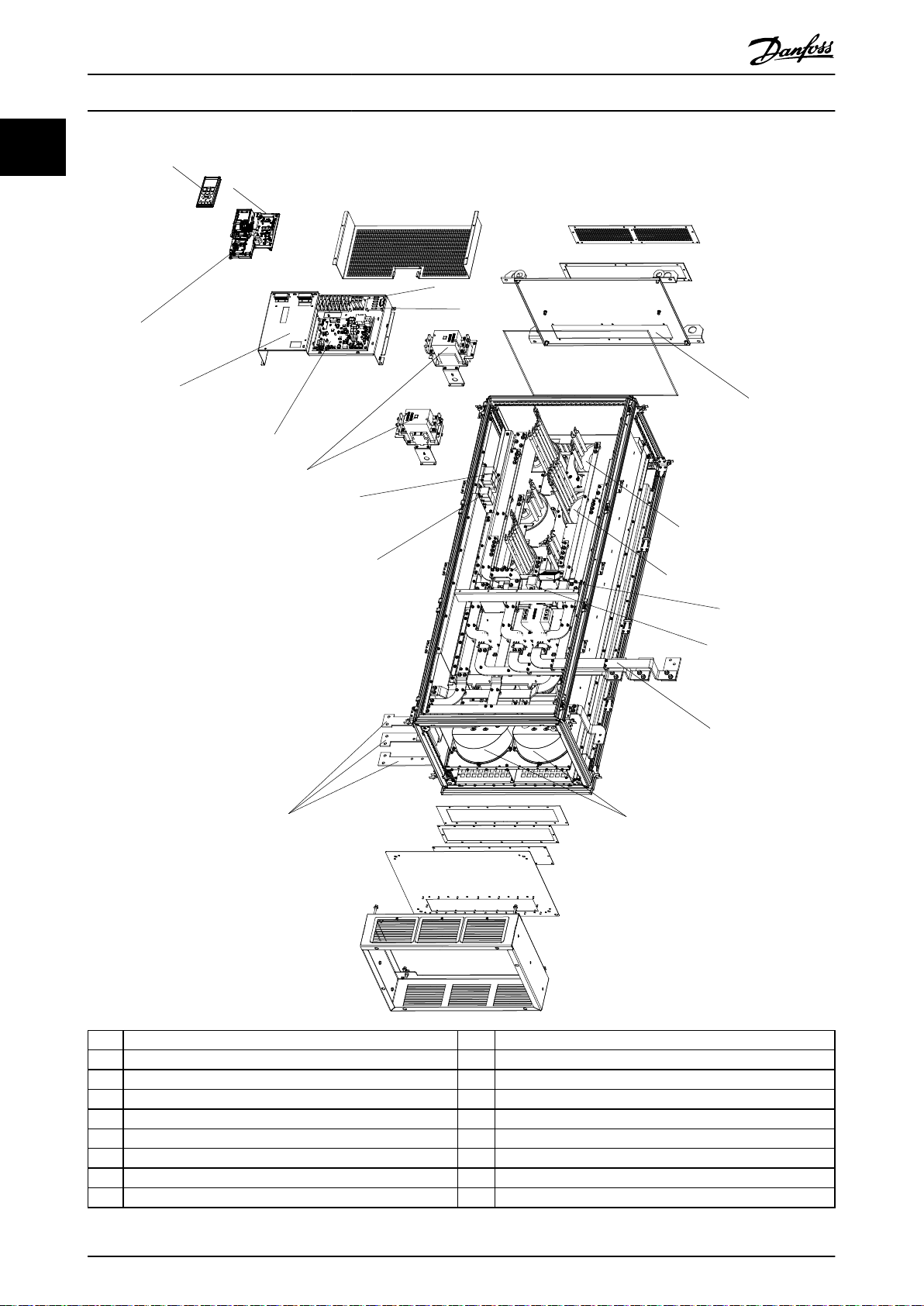
1 Local control panel (LCP) 13 Mains fuses
2 Active lter card (AFC) 14 Mains disconnect
3 Metal oxide varistor (MOV) 15 Mains terminals
4 Soft charge resistors 16 Heat sink fan
5 AC capacitors discharge board 17 DC capacitor bank
6 Mains contactor 18 Current transformer
7 LC inductor 19 RFI dierential mode lter
8 AC capicators 20 RFI common mode lter
9 Mains bus bar to frequency converter input 21 HI inductor
10 IGBT fuses 22 Power card
11 RFI lter 23 Gate drive card
12 Fuses
Illustration 1.3 Enclosure Size D1n/D2n, Filter Enclosure
8 Danfoss A/S © Rev. 04/2015 All rights reserved. MG37A302
Page 13
1
3
2
7
5
4
10
9
8
25
24
6
130BX168.10
20
19
18
17
16
15
14
13
12
11
23
22
21
Introduction
Operating Instructions
1
1
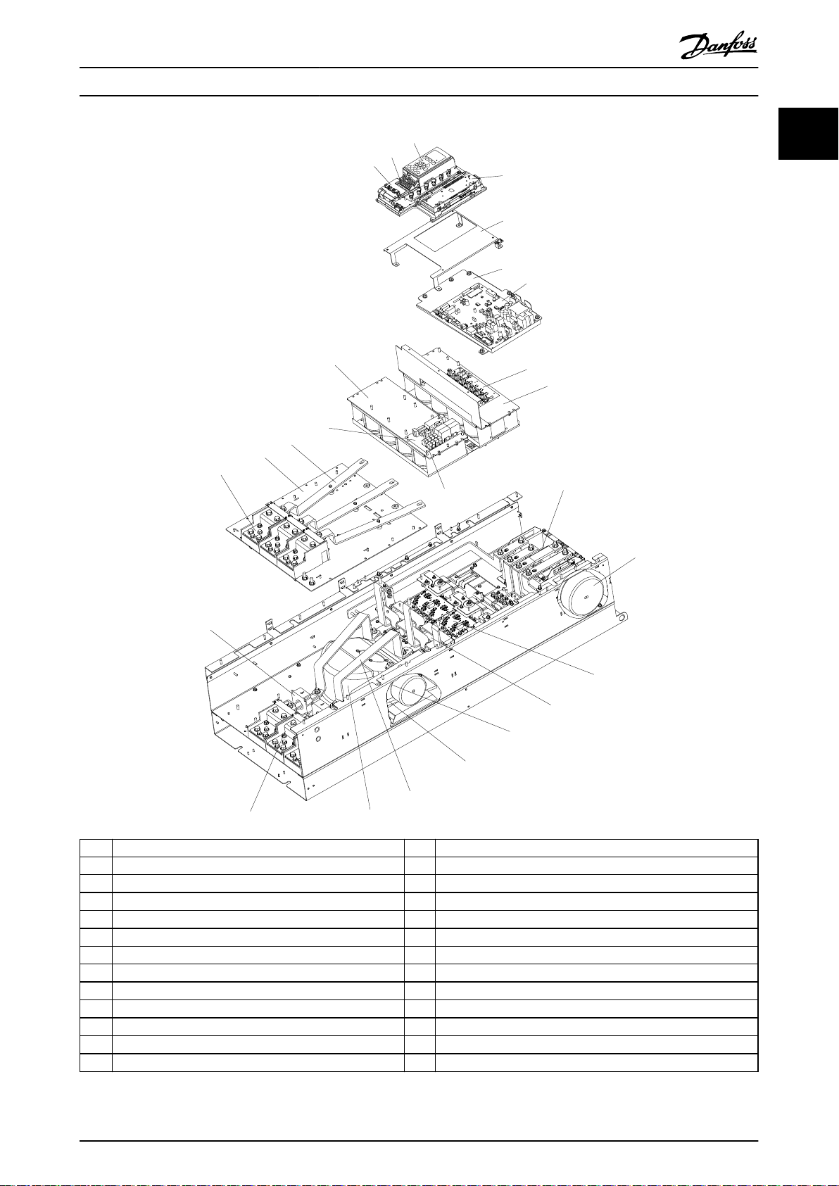
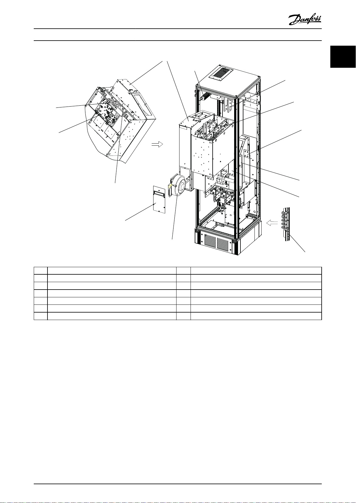
1 Control card 14 SCR and diode
2 Control input terminals 15 Fan inductor (not on all units)
3 Local control panel (LCP) 16 Soft charge resistor assembly
4 Control card C option 17 IGBT output bus bar
5 Mounting bracket 18 Fan assembly
6 Power card mounting plate 19 Output motor terminals
7 Power card 20 Current sensor
8 IGBT gate drive card 21 Mains AC power input terminals
9 Upper capacitor bank assembly 22 Input terminal mounting plate
10 Soft charge fuses 23 AC input bus bar
11 DC inductor 24 Soft charge card
12 Fan transformer 25 Lower capacitor bank assembly
13 IGBT module
Illustration 1.4 Enclosure Size E9, Frequency Converter Enclosure
MG37A302 Danfoss A/S © Rev. 04/2015 All rights reserved. 9
Page 14
130BD572.11
1
5
6
7
9
10
11
12
14
16
17
18
19
20
21
2
3
4
8
13
15
Introduction
VLT® AutomationDrive FC 302 Low Harmonic Drive
132-630 kW
1
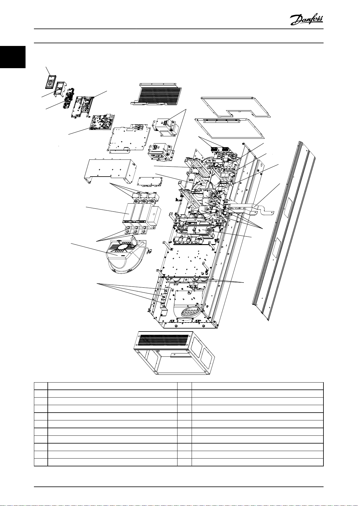
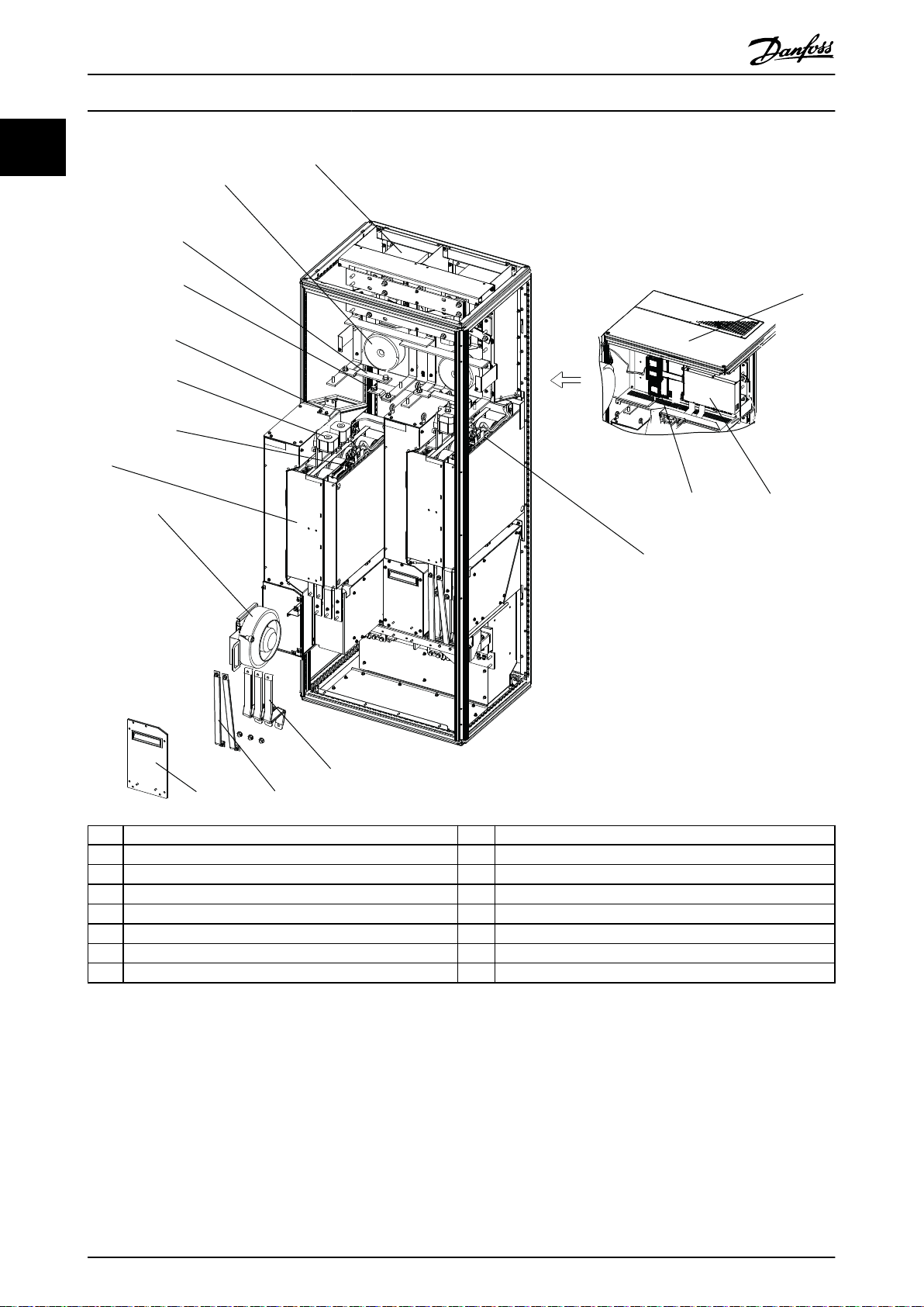
1 Local control panel (LCP) 12 AC capacitor current transducers
2 Active lter card (AFC) 13 Heat sink fan
3 Mains contactors 14 Mains terminals
4 Soft charge resistors 15 Mains disconnect
5 RFI dierential mode lter 16 Mains fuses
6 RFI common mode lter 17 LC inductor
7 Current transformer (CT) 18 HI inductor
8 Mains bus bars to drive output 19 Power card
9 AC capacitors 20 Control card
10 RFI 21 LCP cradle
11 Lower DC capacitor bank
Illustration 1.5 Enclosure Size E9, Filter Enclosure
10 Danfoss A/S © Rev. 04/2015 All rights reserved. MG37A302
Page 15
130BX334.11
2
3
4
5
6
1
Introduction Operating Instructions
1
1
1 Contactor 4 Circuit breaker or disconnect (if purchased)
2 RFI lter 5 AC mains/line fuses (if purchased)
3 Mains AC power input terminals 6 Mains disconnect
Illustration 1.6 Enclosure Size F18, Input Options Cabinet
MG37A302 Danfoss A/S © Rev. 04/2015 All rights reserved. 11
Page 16
130BD573.10
1
2
5
6
7
10
11
15
17
3
4
8
9
13
14
16
18
12
1
Introduction
VLT® AutomationDrive FC 302 Low Harmonic Drive
132-630 kW
1 Local control panel (LCP) 10 Mains bus bars to frequency converter input
2 Active lter card (AFC) 11 Heat sink fans
3 Soft charge resistors 12 Mains terminals (R/L1, S/L2, T/L3) from options cabinet
4 Metal oxide varistor (MOV) 13 RFI dierential mode lter
5 AC capacitors discharge board 14 RFI common mode lter
6 LC inductor 15 Mains contactor
7 HI inductor 16 Power card
8 Mixing fan 17 Control card
9 IGBT fuses 18 LCP cradle
Illustration 1.7 Enclosure Size F18, Filter Cabinet
12 Danfoss A/S © Rev. 04/2015 All rights reserved. MG37A302
Page 17
1
2
5
6
7
8
9
10
11
12
4
3
130BX331.11
13
Introduction Operating Instructions
1
1
1 Rectier module 8 Module heat sink fan
2 DC bus bar 9 Fan door cover
3 SMPS fuse 10 SMPS fuse
4 (Optional) back AC fuse mounting bracket 11 Power card
5 (Optional) middle AC fuse mounting bracket 12 Panel connectors
6 (Optional) front AC fuse mounting bracket 13 Control card
7 Module lifting eye bolts (mounted on a vertical strut)
Illustration 1.8 Enclosure Size F18, Rectier Cabinet
MG37A302 Danfoss A/S © Rev. 04/2015 All rights reserved. 13
Page 18
2
1
16
15
14
13
12
11
10
8
7
6
5
4
9
3
130BX330.11
1
Introduction
VLT® AutomationDrive FC 302 Low Harmonic Drive
132-630 kW
1 Fan transformer 9 Fan door cover
2 DC-link inductor 10 Module heat sink fan
3 Top cover plate 11 Inverter module
4 MDCIC board 12 Panel connectors
5 Control card 13 DC fuse
6 SMPS fuse and fan fuse 14 Mounting bracket
7 Motor output bus bar 15 (+) DC bus bar
8 Brake output bus bar 16 (-) DC bus bar
Illustration 1.9 Enclosure Size F18, Inverter Cabinet
14 Danfoss A/S © Rev. 04/2015 All rights reserved. MG37A302
Page 19
Introduction Operating Instructions
1.4 Enclosure Sizes and Power Ratings
Enclosure size D1n D2n E9 F18
Enclosure protection
Frequency converter
dimensions
[mm/inch]
Frequency converter
weights
[kg/lbs]
Table 1.1 Mechanical Dimensions, Enclosure Sizes D, E, and F
IP 21/54 21/54 21/54 21/54
NEMA Type 1/Type 12 Type 1/Type 12 Type 1/Type 12 Type 1/Type 12
Height 1740/68.5 1740/68.5 2000.7/78.77 2278.4/89.70
Width 915/36.02 1020/40.16 1200/47.24 2792/109.92
Depth 380/14.96 380/14.96 493.5/19.43 605.8/23.85
Maximum
weight
Shipping weight 416/917 476/1050 840/1851 2345/5171
353/777 413/910 676/1490 1900/4189
1.5 Approvals and Certications
Harmonic Analysis
1.6.2
1
1
1.5.1 Approvals
Table 1.2 Compliance Marks: CE, UL, and C-Tick
1.5.2 Compliance with ADN
For compliance with the European Agreement concerning
International Carriage of Dangerous Goods by Inland
Waterways (ADN), refer to ADN-compliant Installation in the
Design Guide.
1.6 Harmonics Overview
1.6.1 Harmonics
Non-linear loads such as found with 6-pulse frequency
converters do not draw current uniformly from the power
line. This non-sinusoidal current has components which are
multiples of the fundamental current frequency. These
components are referred to as harmonics. It is important to
control the total harmonic distortion on the mains supply.
Although the harmonic currents do not directly aect
electrical energy consumption, they generate heat in
wiring and transformers and can impact other devices on
the same power line.
Since harmonics increase heat losses, it is important to
design systems with harmonics in mind to prevent
overloading the transformer, inductors, and wiring.
When necessary, perform an analysis of the system
harmonics to determine equipment eects.
A non-sinusoidal current is transformed with a Fourier
series analysis into sine-wave currents at dierent
frequencies, that is, dierent harmonic currents IN with 50
Hz or 60 Hz as the fundamental frequency.
Abbreviation Description
f
1
I
1
U
1
I
n
U
n
n Harmonic order
Table 1.3 Harmonics-related Abbreviations
Fundamental
Current I
Frequency
[Hz]
Table 1.4 Fundamental and Harmonic Currents
Current Harmonic current
I
Input current 1.0 0.9 0.5 0.2 < 0.1
Fundamental frequency (50 Hz or 60 Hz)
Current at the fundamental frequency
Voltage at the fundamental frequency
Current at the nth harmonic frequency
Voltage at the nth harmonic frequency
Harmonic current (In)
current (I1)
RMSI1
I
5
1
50 250 350 550
I
7
I
I
5
7
I
11-49
I
11
Table 1.5 Harmonic Currents Compared to the RMS Input
Current
The voltage distortion on the mains supply voltage
depends on the size of the harmonic currents multiplied
MG37A302 Danfoss A/S © Rev. 04/2015 All rights reserved. 15
Page 20
Introduction
VLT® AutomationDrive FC 302 Low Harmonic Drive
132-630 kW
1
by the mains impedance for the frequency in question. The
total voltage distortion (THDi) is calculated based on the
individual voltage harmonics using this formula:
THDi =
U25 + U27 + ... + U2n
U
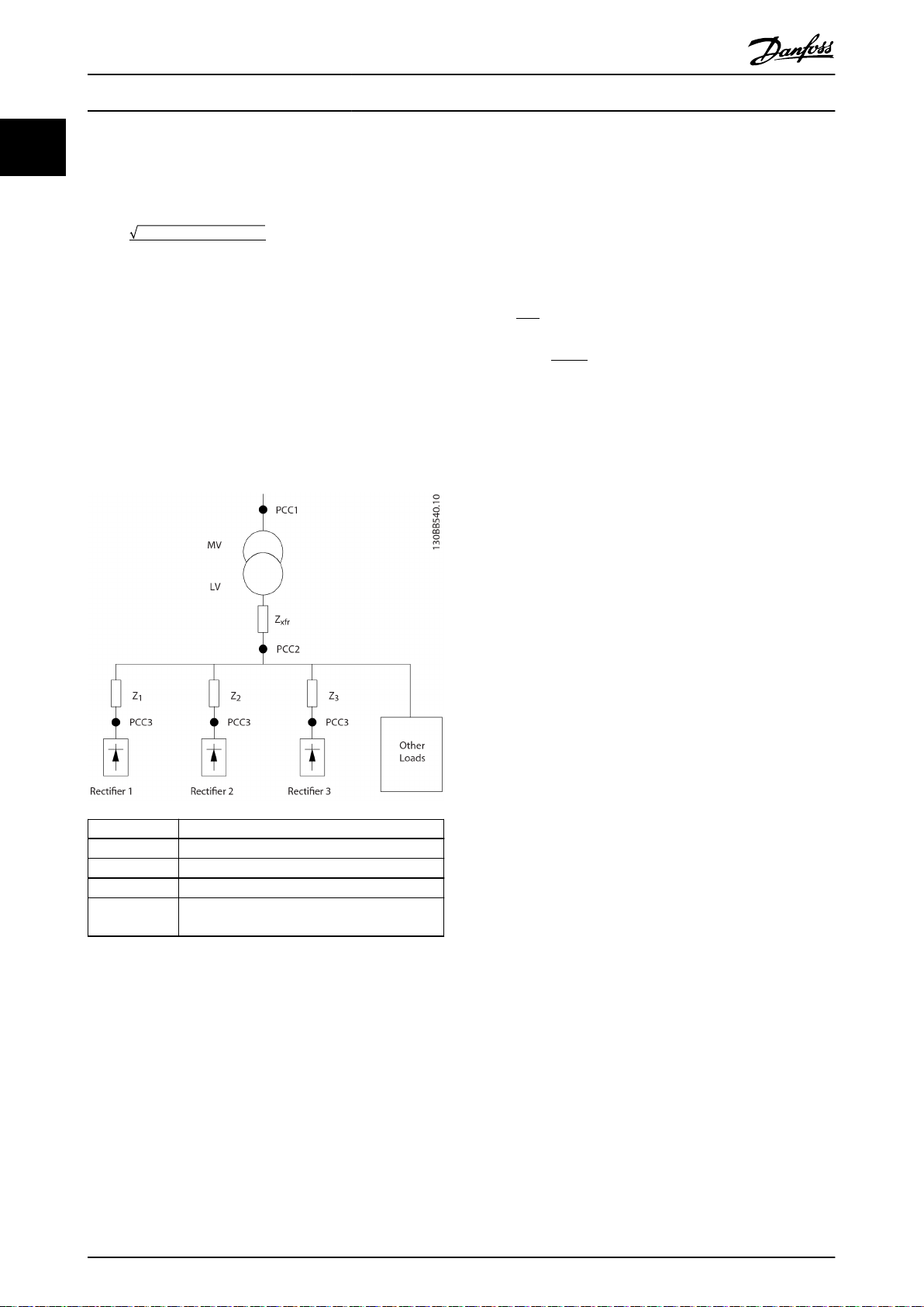
1.6.3 Eect of Harmonics in a Power
Distribution System
In Illustration 1.10, a transformer is connected on the
primary side to a point of common coupling PCC1, on the
medium voltage supply. The transformer has an impedance
Z
and feeds a number of loads. The point of common
xfr
coupling where all loads are connected is PCC2. Each load
is connected through cables that have an impedance Z1,
Z2, Z3.
PCC, the conguration of the distribution system and
relevant impedances must be known.
A commonly used term for describing the impedance of a
grid is the short-circuit ratio R
. R
is dened as the ratio
sce
sce
between the short circuit apparent power of the supply at
the PCC (Ssc) and the rated apparent power of the load
(S
).
equ
S
sce
sc
=
S
equ
2
U
Z
supply
and S
=
sc
equ
= U × I
equ
R
where S
Negative eects of harmonics
Harmonic currents contribute to system losses (in
•
cabling, and transformer).
Harmonic voltage distortion causes disturbance
•
to other loads and increases losses in other loads.
PCC Point of common coupling
MV Medium voltage
LV Low voltage
Z
xfr
Z
#
Illustration 1.10 Small Distribution System
Transformer impedance
Modeling resistance and inductance in the
wiring
Harmonic currents drawn by non-linear loads cause
distortion of the voltage because of the voltage drop on
the impedances of the distribution system. Higher
impedances result in higher levels of voltage distortion.
Current distortion relates to apparatus performance and it
relates to the individual load. Voltage distortion relates to
system performance. It is not possible to determine the
voltage distortion in the PCC knowing only the harmonic
performance of the load. To predict the distortion in the
16 Danfoss A/S © Rev. 04/2015 All rights reserved. MG37A302
Page 21
Introduction
Operating Instructions
1.6.4 IEC Harmonic Standards
The mains voltage is rarely a uniform sinusoidal voltage with constant amplitude and frequency because loads that draw
non-sinusoidal currents from the mains have non-linear characteristics.
Harmonics and voltage uctuations are 2 forms of low-frequency mains interference. They have a dierent appearance at
their origin than at any other point in the mains system when a load is connected. So, a range of inuences must be
determined collectively when assessing the eects of mains interference. These inuences include the mains feed, structure,
and loads.
Mains interference can cause the following:
Undervoltage warnings
Incorrect voltage measurements due to distortion of the sinusoidal mains voltage.
•
Cause incorrect power measurements because only RMS-true measuring takes harmonic content into account.
•
Higher functional losses
Harmonics reduce the active power, apparent power, and reactive power.
•
Distort electrical loads resulting in audible interference in other devices, or in worst case, even destruction.
•
Shorten the lifetime of devices as a result of heating.
•
1
1
In most of Europe, the basis for the objective assessment of the quality of mains power is the Electromagnetic Compatibility
of Devices Act (EMVG). Compliance with these regulations ensures that all devices and networks connected to electrical
distribution systems
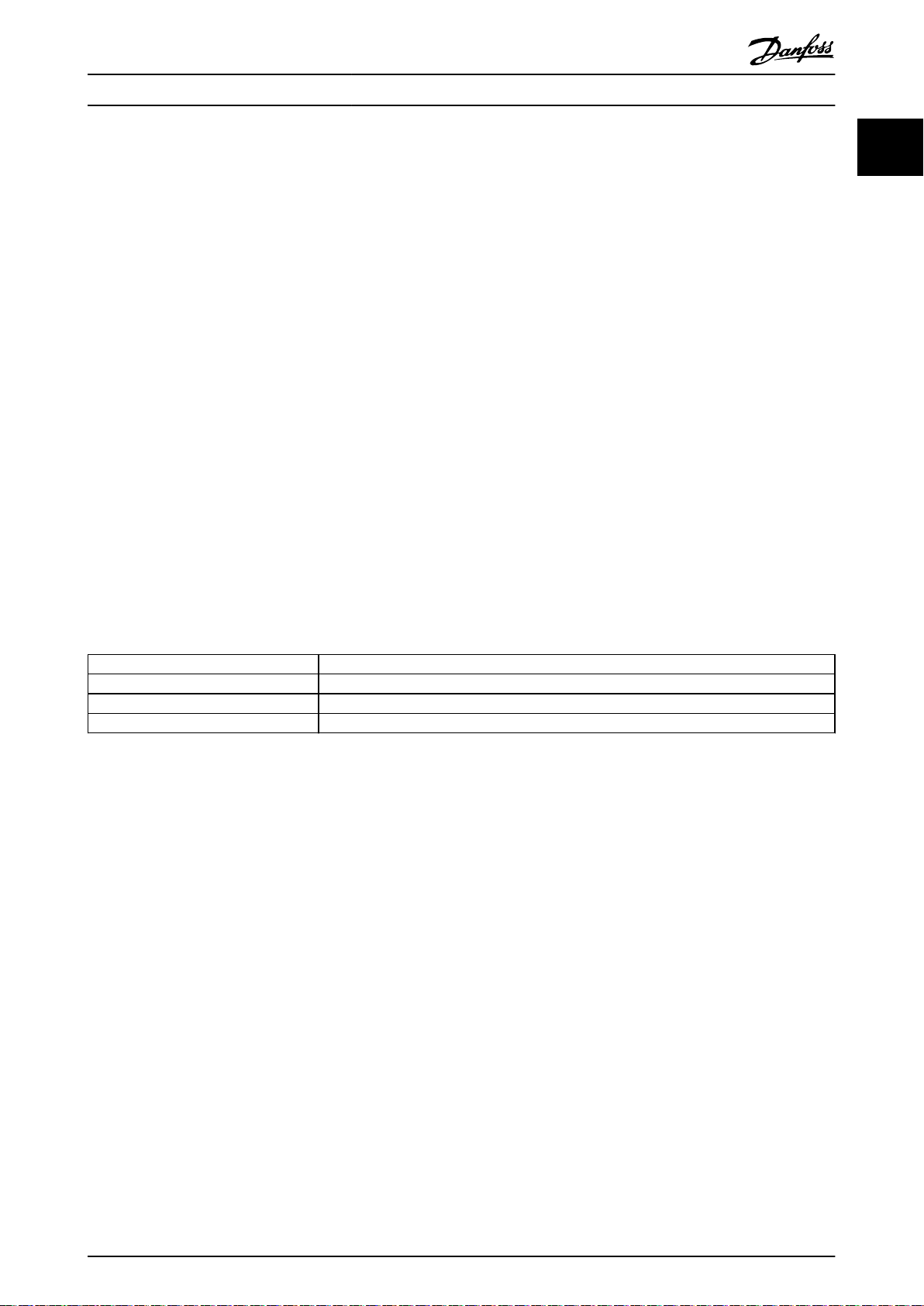
Standard Denition
EN 61000-2-2, EN 61000-2-4, EN 50160 Dene the mains voltage limits required for public and industrial power grids.
EN 61000-3-2, 61000-3-12 Regulate mains interference generated by connected devices in lower current products.
EN 50178 Monitors electronic equipment for use in power installations.
Table 1.6 EN Design Standards for Mains Power Quality
There are 2 European standards that address harmonics in the frequency range from 0 Hz to 9 kHz:
EN 61000-2-2 (Compatibility Levels for Low-Frequency Conducted Disturbances and Signalling in Public Low-Voltage Power
Supply Systems) states the requirements for compatibility levels for PCC (point of common coupling) of low-voltage AC
systems on a public supply network. Limits are specied only for harmonic voltage and total harmonic distortion of the
voltage. EN 61000-2-2 does not dene limits for harmonic currents. In situations where the total harmonic distortion
THD(V)=8%, PCC limits are identical to those limits specied in the EN 61000-2-4 Class 2.
EN 61000-2-4 (Compatibility Levels for Low-Frequency Conducted Disturbances and Signalling in Industrial Plants) states the
requirements for compatibility levels in industrial and private networks. The standard further denes the following 3 classes
of electromagnetic environments:
Class 1 relates to compatibility levels that are less than the public supply network, which
•
sensitive to disturbances (lab equipment, some automation equipment, and certain protection devices).
Class 2 relates to compatibility levels that are equal to the public supply network. The class applies to PCCs on the
•
public supply network and to IPCs (internal points of coupling) on industrial or other private supply networks. Any
equipment designed for operation on a public supply network is allowed in this class.
Class 3 relates to compatibility levels greater than the public supply network. This class applies only to IPCs in
•
industrial environments. Use this class where the following equipment is found:
full their intended purpose without generating problems.
aects equipment
MG37A302 Danfoss A/S © Rev. 04/2015 All rights reserved. 17
Page 22
Introduction
VLT® AutomationDrive FC 302 Low Harmonic Drive
132-630 kW
1
Large converters.
-
Welding machines.
-
Large motors starting frequently.
-
Loads that change quickly.
-
Typically, a class cannot be dened ahead of time without taking into account the intended equipment and processes to be
used in the environment. VLT® AutomationDrive FC 302 Low Harmonic Drive observes the limits of Class 3 under typical
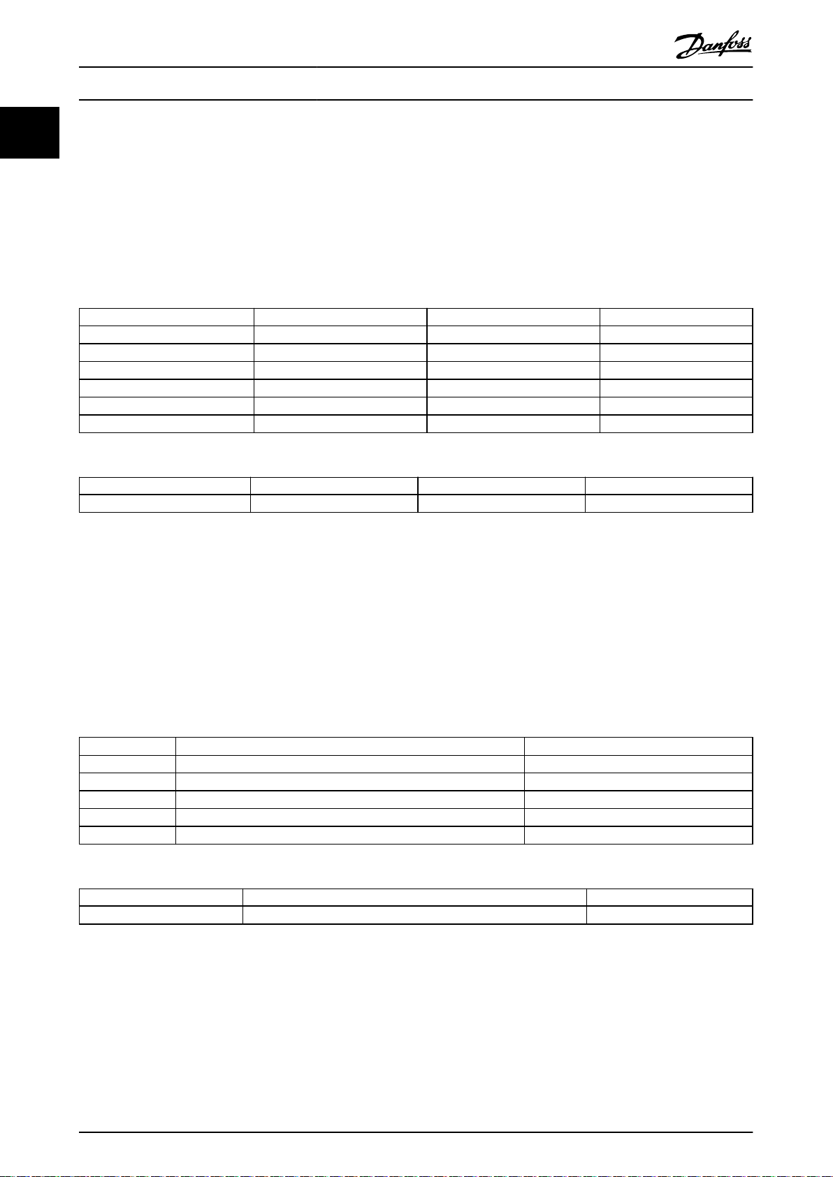
supply system conditions (RSC>10 or
Harmonic order (h) Class 1 (Vh%) Class 2 (Vh%) Class 3 (Vh%)
5 3 6 8
7 3 5 7
11 3 3.5 5
13 3 3 4.5
17 2 2 4
17˂h≤49 2.27 x (17/h) – 0.27 2.27 x (17/h) – 0.27 4.5 x (17/h) – 0.5
Table 1.7 Compatibility Levels for Harmonics
Class 1 Class 2 Class 3
THD(V)
Table 1.8 Compatibility Levels for the Total Harmonic Voltage Distortion THD(V)
Vk Line
<10%).
5% 8% 10%
IEEE Harmonic Standards
1.6.5
The IEEE 519 standard (Recommended Practices and Requirements for Harmonic Control in Electrical Power Systems)
provides specic limits for harmonic voltages and currents for individual components within the supply network. The
standard also provides limits for the sum of all loads at the point of common coupling (PCC).
To determine permissible harmonic voltage levels, IEEE 519 uses a ratio between the supply short-circuit current and the
maximum current of the individual load. For permissible harmonic voltage levels for individual loads, see Table 1.9. For
permissible levels for all loads connected to the PCC, see Table 1.10.
ISC/IL (R
10 2.5–3% Weak grid
20 2.0–2.5% 1–2 large loads
50 1.0–1.5% A few high-output loads
100 0.5–1% 5–20 medium-output loads
1000 0.05–0.1% Strong grid
Table 1.9 Permissible Voltage THD at the PCC for Each Individual Load
Voltage at the PCC Permissible individual harmonic voltages Permissible THD(V)
V
Line
Table 1.10 Permissible Voltage THD at the PCC for all Loads
) Permissible individual harmonic voltages Typical areas
SCE
≤69 kV 3% 5%
Limit harmonic currents to
specied levels, as shown in Table 1.11. IEEE 519 utilises a ratio between the supply short-circuit
current and the maximum current consumption at the PCC, averaged over 15 minutes or 30 minutes. In certain instances
when dealing with harmonic limits containing low harmonic numbers, the IEEE 519 limits are lower than the 61000-2-4
limits. Low harmonic drives observe the total harmonic distortion as dened in IEEE 519 for all R
harmonic current fullls table 10–3 in IEEE 519 for R
18 Danfoss A/S © Rev. 04/2015 All rights reserved. MG37A302
sce
≥20.
. Each individual
sce
Page 23

Introduction Operating Instructions
ISC/IL (R
<20 4% 2.0% 1.5% 0.6% 0.3% 5%
20<50 7% 3.5% 2.5% 1.0% 0.5% 8%
50<100 10% 4.5% 4.0% 1.5% 0.7% 12%
100<1000 12% 5.5% 5.0% 2.0% 1.0% 15%
>1000 15% 7.0% 6.0% 2.5% 1.4% 20%
Table 1.11 Permissible Harmonic Currents at the PCC
The VLT® AutomationDrive FC 302 Low Harmonic Drive complies with the following standards:
) h<11 11≤h<17 17≤h<23 23≤h<35 35≤h Total demand
SCE
IEC61000-2-4
•
IEC61000-3-4
•
IEEE 519
•
G5/4
•
distortion TDD
1
1
MG37A302 Danfoss A/S © Rev. 04/2015 All rights reserved. 19
Page 24
2
Safety
2 Safety
2.1 Safety
VLT® AutomationDrive FC 302 Low Harmonic Drive
132-630 kW
2.3
Safety Precautions
The following symbols are used in this document:
WARNING
Indicates a potentially hazardous situation which could
result in death or serious injury.
CAUTION
Indicates a potentially hazardous situation which could
result in minor or moderate injury. It may also be used
to alert against unsafe practices.
NOTICE
Indicates important information, including situations that
may result in damage to equipment or property.
2.2 Qualied Personnel
Correct and reliable transport, storage, installation,
operation and maintenance are required for the safe
operation of the frequency converter. Only qualied
personnel are allowed to install or operate this equipment.
Qualied personnel is dened as trained sta, who are
authorised to install, commission, and maintain equipment,
systems and circuits in accordance with pertinent laws and
regulations. Additionally, qualied personnel are familiar
with the instructions and safety measures described in this
document.
WARNING
HIGH VOLTAGE
Frequency converters contain high voltage when
connected to AC mains input power. Qualied personnel
only should perform installation, start up, and
maintenance. Failure to perform installation, start up,
and maintenance by qualied personnel could result in
death or serious injury.
WARNING
UNINTENDED START
When the frequency converter is connected to AC mains,
the motor may start at any time. The frequency
converter, motor, and any driven equipment must be in
operational readiness. Failure to be in operational
readiness when the frequency converter is connected to
AC mains could result in death, serious injury,
equipment, or property damage.
WARNING
DISCHARGE TIME
Frequency converters contain DC-link capacitors that can
remain charged even when the frequency converter is
not powered. To avoid electrical hazards, disconnect AC
mains, any permanent magnet type motors, and any
remote DC-link power supplies, including battery backups, UPS, and DC-link connections to other frequency
converters. Wait for the capacitors to fully discharge
before performing any service or repair work. The
amount of wait time is listed in the Discharge Time table.
Failure to wait the specied time after power has been
removed before doing service or repair could result in
death or serious injury.
Voltage [V] Power range [kW] Minimum waiting time
(minutes)
380–500
Table 2.1 Discharge Times
20 Danfoss A/S © Rev. 04/2015 All rights reserved. MG37A302
132–200 kW 20
250–630 kW 40
Page 25

Mechanical Installation Operating Instructions
3 Mechanical Installation
3.1 Installation Site Checklist
3.1.1 Planning the Installation Site
CAUTION
It is important to plan the installation of the frequency
converter. Neglecting to plan may result in extra work
during and after installation.
Select the best possible operation site by considering
the following:
Ambient operating temperature.
•
Installation method.
•
How to cool the unit.
•
Position of the frequency converter.
•
Cable routing.
•
Ensure that the power source supplies the correct
•
voltage and necessary current.
Ensure that the motor current rating is within the
•
maximum current from the frequency converter.
If the frequency converter is without built-in
•
fuses, ensure that the external fuses are rated
correctly.
Motor size and frequency converter
-
power must match for proper overload
protection.
If frequency converter rating is less than
-
that of the motor, full motor output is
impossible.
3 3
Equipment Pre-Installation Checklist
3.1.2
Before unpacking the frequency converter,
•
examine the packaging for signs of damage. If
the unit is damaged, refuse delivery, and
immediately contact the shipping company to
claim the damage.
Before unpacking the frequency converter, locate
•
it as close as possible to the
Compare the model number on the nameplate to
•
what was ordered to verify the proper
equipment.
Ensure that each of the following are rated for
•
the same voltage:
Mains (power)
-
Frequency converter
-
Motor
-
Ensure that the output current rating is equal to
•
or greater than the motor full load current for
peak motor performance.
nal installation site.
MG37A302 Danfoss A/S © Rev. 04/2015 All rights reserved. 21
Page 26
130BD600.10
CHASSIS/ IP20 Tamb.50
C/122 F
V LT
MADE IN DENMARK
R
P/N: 131X3537 S/N: 010122G430
0.37kW/ 0.50HP
IN: 3x200-240V 50/60Hz 2.2A
OUT: 3x0-Vin 0-1000Hz 2.4A
o
CAUTION:
See manual for special condition/mains fuse
voir manual de conditions speclales/fusibles
WARNING:
Stored charge, wait 4 min.
Charge residuelle, attendez 4 min.
* 1 3 1
X
3 5 3 7 0 1 0 1 2 2 G 4 3 0 *
`
Automation Drive
www.danfoss.com
T/C: FC-302PK37T2E20H1BGXXXXSXXXXA6BKC4XXXD0
Listed 76X1 E134261 Ind. Contr. Eq.
o
`
1
2
4
5
6
7
8
9
10
3
Mechanical Installation
VLT® AutomationDrive FC 302 Low Harmonic Drive
132-630 kW
3.2 Unpacking
3.2.1 Items Supplied
Items supplied may vary according to product congu-
ration.
33
Make sure that the items supplied and the
•
information on the nameplate correspond to the
order conrmation.
Check the packaging and the frequency converter
•
visually for damage caused by inappropriate
handling during shipment. File any claim for
damage with the carrier. Retain damaged parts
for clarication.
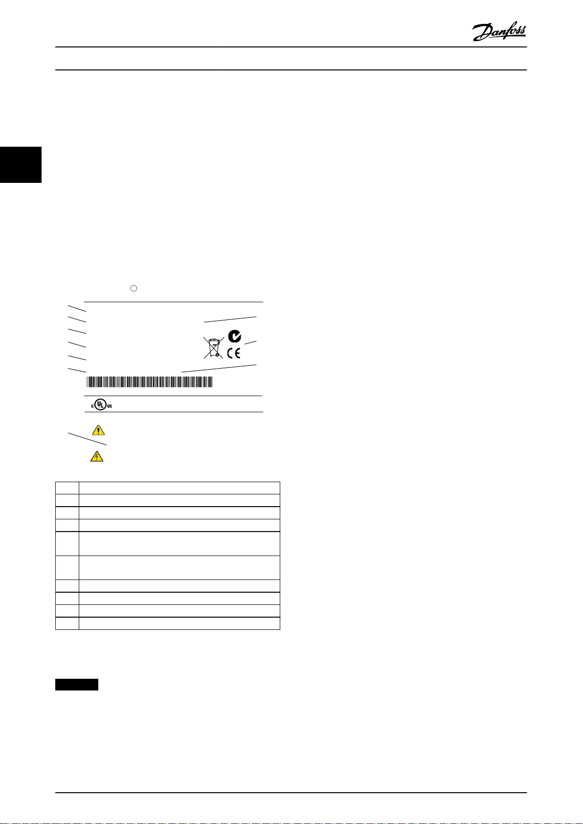
1 Type code
2 Order number
3 Serial number
4 Power rating
Input voltage, frequency and current (at low/high
5
voltages)
Output voltage, frequency and current (at low/high
6
voltages)
7 Enclosure type and IP rating
8 Maximum ambient temperature
9 Certications
10 Discharge time (Warning)
Illustration 3.1 Product Nameplate (Example)
NOTICE
Do not remove the nameplate from the frequency
converter (loss of warranty).
22 Danfoss A/S © Rev. 04/2015 All rights reserved. MG37A302
Page 27
Mechanical Installation Operating Instructions
3.3 Mounting
3.3.1 Cooling and Airow
Cooling
Obtain cooling by taking air in through the plinth in the front and out of the top, in and out the back of the unit, or by
combining the cooling possibilities.
Back cooling
The backchannel air can also be ventilated in and out the back. This
from outside the facility and return the heat losses outside the facility thus reducing air-conditioning requirements.
Airow
Secure the necessary airow over the heat sink. The ow rate is shown in Table 3.1.
oers a solution where the backchannel could take air
3 3
Enclosure protection Enclosure size
D1n
D2n
IP21/NEMA 1
IP54/NEMA 12
Table 3.1 Heat Sink Air Flow
E9
F18
NOTICE
For the frequency converter section, the fan runs for the
following reasons:
AMA.
•
DC hold.
•
Pre-mag.
•
DC brake.
•
60% of nominal current is exceeded.
•
Specic heat sink temperature exceeded (power
•
size dependent).
Specic power card ambient temperature
•
exceeded (power size dependent).
Specic control card ambient temperature
•
exceeded.
Once the fan is started, it runs for minimum 10 minutes.
Door fan/top fan airow
Total airow of multiple fans
3 door fans, 442 m3/h
2+1=2x170+102
3 door fan, 544 m3/h
2+1=2x170+204
4 door fans, 680 m3/h (400 cfm)
(2+2, 4x170=680)
6 door fans, 3150 m3/h (1854
cfm)
(6x525=3150)
Heat sink fan
Total airow for multiple fans
2 heat sink fans, 1185 m3/h
(1+1=765+544)
2 heat sink fans, 1605 m3/h
(1+1=765+840)
2 heat sink fans, 2675 m3/h
(1574 cfm)
(1+1, 1230+1445=2675)
5 heat sink fans, 4485 m3/h
(2639 cfm)
2+1+2, ((2x765)+(3x985)=4485)
NOTICE
For the active lter, the fan runs for the following
reasons:
Active lter running.
•
Active lter not running, but mains current
•
exceeding the limit (power size dependent).
Specic heat sink temperature exceeded (power
•
size dependent).
Specic power card ambient temperature
•
exceeded (power size dependent).
Specic control card ambient temperature
•
exceeded.
Once the fan is started, it runs for minimum 10 minutes.
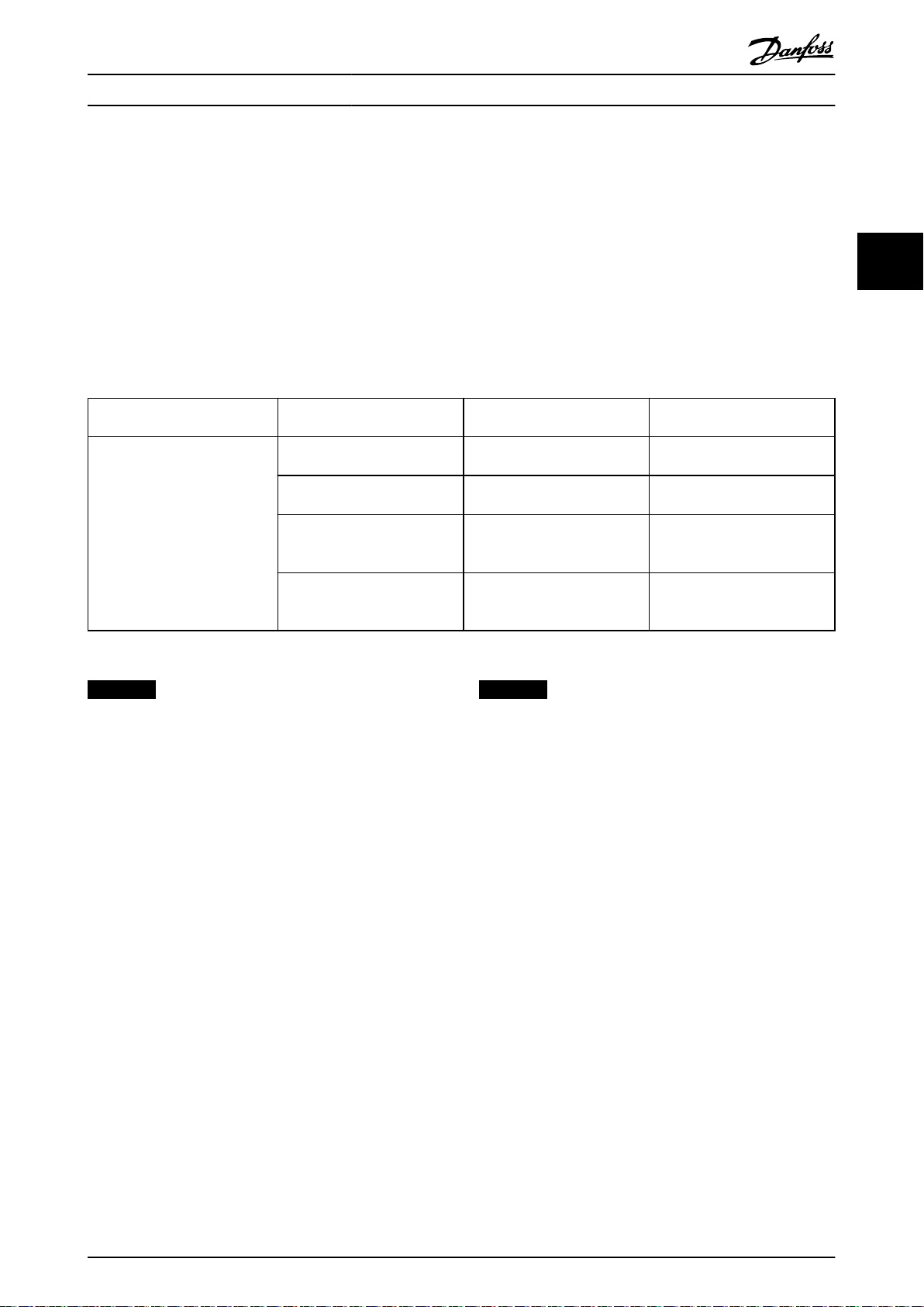
External ducts
If additional duct work is added externally to the Rittal
cabinet, calculate the pressure drop in the ducting. Use
Illustration 3.2, Illustration 3.3, and Illustration 3.4 to derate
the frequency converter according to the pressure drop.
MG37A302 Danfoss A/S © Rev. 04/2015 All rights reserved. 23
Page 28
90
80
70
60
50
40
30
20
10
0
0 0.5 4.9 13 27.3 45.9 66 89.3 115.7 147
(%)
(Pa)
Pressure Increase
Drive Derating
130BB007.10
90
80
70
60
50
40
30
20
10
0
(%)
Drive Derating
0 0.2 0.6 2.2 5.8 11.4 18.1 30.8 152.8 210.8
(Pa)
Pressure Change
130BB011.10
69.5
90
80
70
60
50
40
30
20
10
0
(%)
Drive Derating
0 25 50 75 100 125 150 175 225
130BB190.10
200
Pressure Change
1
130BE111.10
130BC170.10
Lifting Holes
Mechanical Installation
VLT® AutomationDrive FC 302 Low Harmonic Drive
132-630 kW
Lifting
3.3.2
Lift the frequency converter using the dedicated lifting
eyes. For all D-frames, use a bar to avoid bending the
lifting holes of the frequency converter.
33
Illustration 3.2 D-Enclosure Derating vs. Pressure Change
Frequency Converter Air Flow: 450 cfm (765 m3/h)
1 Lifting holes
Illustration 3.5 Recommended Lifting Method, Enclosure Size
D1n/D2n
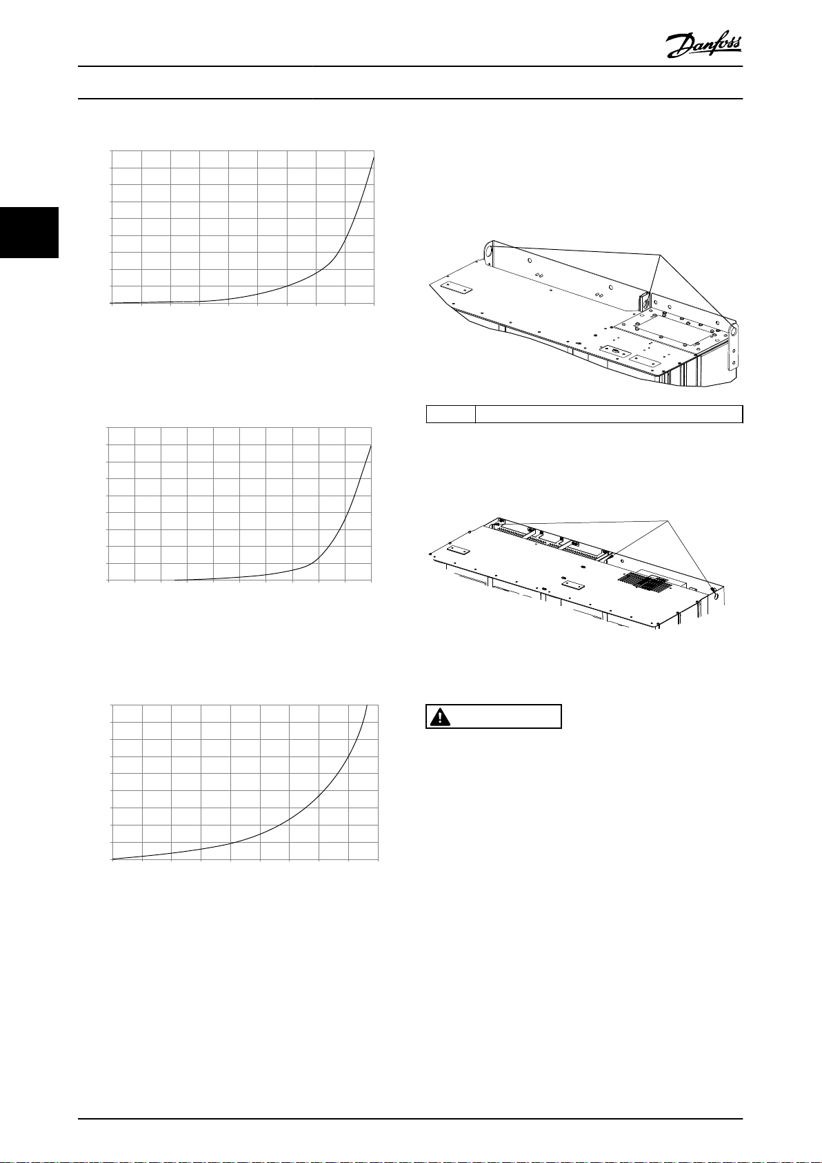
Illustration 3.3 E-Enclosure Derating vs. Pressure Change
Frequency Converter Air Flow: 850 cfm (1445 m3/h)
Illustration 3.4 F-Enclosure Derating vs. Pressure Change
Frequency Converter Air Flow: 580 cfm (985 m3/h)
24 Danfoss A/S © Rev. 04/2015 All rights reserved. MG37A302
Illustration 3.6 Recommended Lifting Method, Enclosure Size
E9
WARNING
The lifting bar must be able to handle the weight of the
frequency converter. See chapter 8.2 Mechanical
Dimensions for the weight of the dierent enclosure
sizes. Maximum diameter for bar is 2.5 cm (1 inch). The
angle from the top of the frequency converter to the
lifting cable should be 60° or greater.
Page 29
1
2
130BD574.10
Mechanical Installation Operating Instructions
1 Lifting holes for the lter
2 Lifting holes for the frequency converter
Illustration 3.7 Recommended Lifting Method, Enclosure Size
F18
3 3
NOTICE
A spreader bar is also an acceptable way to lift the Fframe.
NOTICE
The F18 pedestal is packaged separately and included in
the shipment. Mount the frequency converter on the
pedestal in its nal location. The pedestal allows proper
airow and cooling.
MG37A302 Danfoss A/S © Rev. 04/2015 All rights reserved. 25
Page 30
64.5
[2.5]
20.0
[0.8]
40.0
[1.6]
560.0
[22.0]
327.4
[12.9]
289.4
[11.4]
227.8
[9.0]
246.0
[9.7]
350.0
[13.8]
397.3
[15.6]
240.0
[9.4]
220.0
[8.7]
235.0
[9.3]
42.3
[1.7]
8X 14.0
[0.6]
8X 25.0
[1.0]
1
130BE112.10
Mechanical Installation
VLT® AutomationDrive FC 302 Low Harmonic Drive
132-630 kW
3.3.3 Cable Entry and Anchoring
Cables enter the unit through gland plate openings in the bottom. Illustration 3.8, Illustration 3.9, Illustration 3.10, and
Illustration 3.11 show gland entry locations and detailed views of anchoring hole dimensions.
33
Bottom View, D1n/D2n
1 Cable entry locations
Illustration 3.8 Cable Entry Diagram, Enclsoure Size D1n
26 Danfoss A/S © Rev. 04/2015 All rights reserved. MG37A302
Page 31

130BE113.10
64.5
[2.5]
560.0
[22.0]
422.4
[16.6]
384.8
[15.1]
18.6
[0.7]
27.5
[1.1]
227.8
[9.0]
220.0
[8.7]
235.0
[9.3]
40.4
[1.6]
8X 25.0
[1.0]
8X 14.0
[0.6]
330.0
[13.0]
470.4
[18.5]
390.0
[15.4]
246.0
[9.7]
1
Mechanical Installation Operating Instructions
3 3
1 Cable entry locations
Illustration 3.9 Cable Entry Diagram, Enclsoure Size D2n
MG37A302 Danfoss A/S © Rev. 04/2015 All rights reserved. 27
Page 32

1
130BC586.10
Mechanical Installation
Bottom view, enclosure size E9
VLT® AutomationDrive FC 302 Low Harmonic Drive
132-630 kW
33
1 Cable entry locations
Illustration 3.10 Cable Entry Diagram, E9
28 Danfoss A/S © Rev. 04/2015 All rights reserved. MG37A302
Page 33

2
3
5
6
130BC587.10
4
1
Mechanical Installation
Bottom view, F18
Operating Instructions
3 3
1 Mains cable entry 4 Motor cable entry
2 Option enclosure 5 Inverter enclosure
3 Filter enclosure 6 Rectier enclosure
Illustration 3.11 Cable Entry Diagram, F18
MG37A302 Danfoss A/S © Rev. 04/2015 All rights reserved. 29
Page 34

784.6
[30.9]
78.3
[3.1]
245.8
[9.7]
39.2
[1.5]
267.4
[10.5]
266.2
[10.5]
204.0
[8.0]
259.7
[10.2]
695.9
[27.4]
83.5
[3.3]
167.0
[6.6]
88.0
[3.5]
476.0
[18.7]
483.0
[19.0]
1080.5
[42.5]
29.0
[1.1]
121.3
[4.8]
MAINS INPUT TERMINALS
MOTOR
OUTPUT TERMINALS
130BE114.10
Mechanical Installation
VLT® AutomationDrive FC 302 Low Harmonic Drive
132-630 kW
3.3.4 Terminal Locations for Enclosure Size D1n/D2n
33
Illustration 3.12 Terminal Locations, Enclosure Size D1n
30 Danfoss A/S © Rev. 04/2015 All rights reserved. MG37A302
Page 35

845.7
[33.3]
108.0
[4.3]
257.6
[10.1]
268.9
[10.6]
1005.1
[39.6]
486.8
[19.2]
167.0
[6.6]
786.7
[31.0]
259.7
[10.2]
204.0
[8.0]
88.0
[3.5]
266.2
[10.5]
83.5
[3.3]
121.8
[4.8]
54.0
[2.1]
29.0
[1.1]
476.0
[18.7]
MOTOR
OUTPUT TERMINALS
MAINS INPUT TERMINALS
130BE115.10
Mechanical Installation Operating Instructions
3 3
Illustration 3.13 Terminal Locations, Enclosure Size D2n
Allow for bend radius of heavy power cables.
NOTICE
All D-frames are available with standard input terminals, fuse, or disconnect switch.
MG37A302 Danfoss A/S © Rev. 04/2015 All rights reserved. 31
Page 36

130BC604.10
383
[15.1]
518.0
[20.4]
90.0
[3.5]
153.8
[6.1]
517.5
[20.4]
225.0
[8.9]
112.5
[4]
900.0
[35.4]
368.3
[14.5]
323.3
[12.7]
180.0
[7.1]
90.0
[3.5]
168.7
[6.6]
MAINS
INPUT TERMINAL
MOTOR
OUTPUT TERMINAL
104[4.1]
35[1.4]
10[0.4]
0[0.0]
0[0.0]
40[1.6]
78[3.1]
0[0.0]
26[1.0]
26[1.0]
176FA271.10
Mechanical Installation
VLT® AutomationDrive FC 302 Low Harmonic Drive
132-630 kW
3.3.5 Terminal Locations for Enclosure Size E9
33
Illustration 3.14 Terminal Locations, Enclsoure Size E9
Allow for bend radius of heavy power cables.
NOTICE
All E-frames are available with standard input terminals, fuse, or disconnect switch.
Illustration 3.15 Close-up Terminal Diagrams
32 Danfoss A/S © Rev. 04/2015 All rights reserved. MG37A302
Page 37

1 2 3
4
0.0[0.00]
76.4[3.01]
128.4[5.05]
119.0[4.69]
171.0[6.73]
294.6[11.60]
344.0[13.54]
3639[14.33]
438.9[17.28]
75.3[2.96]
150.3[5.92]
154.0[6.06]
219.6[18.65]
0.0[0.00]
244.4[9.62]
244.4[1.75]
939.0[36.97]
1031.4[40.61]
0.0[0.00]
134.6[5.30]
130BA851.12
0.0[1.75]
Mechanical Installation
Operating Instructions
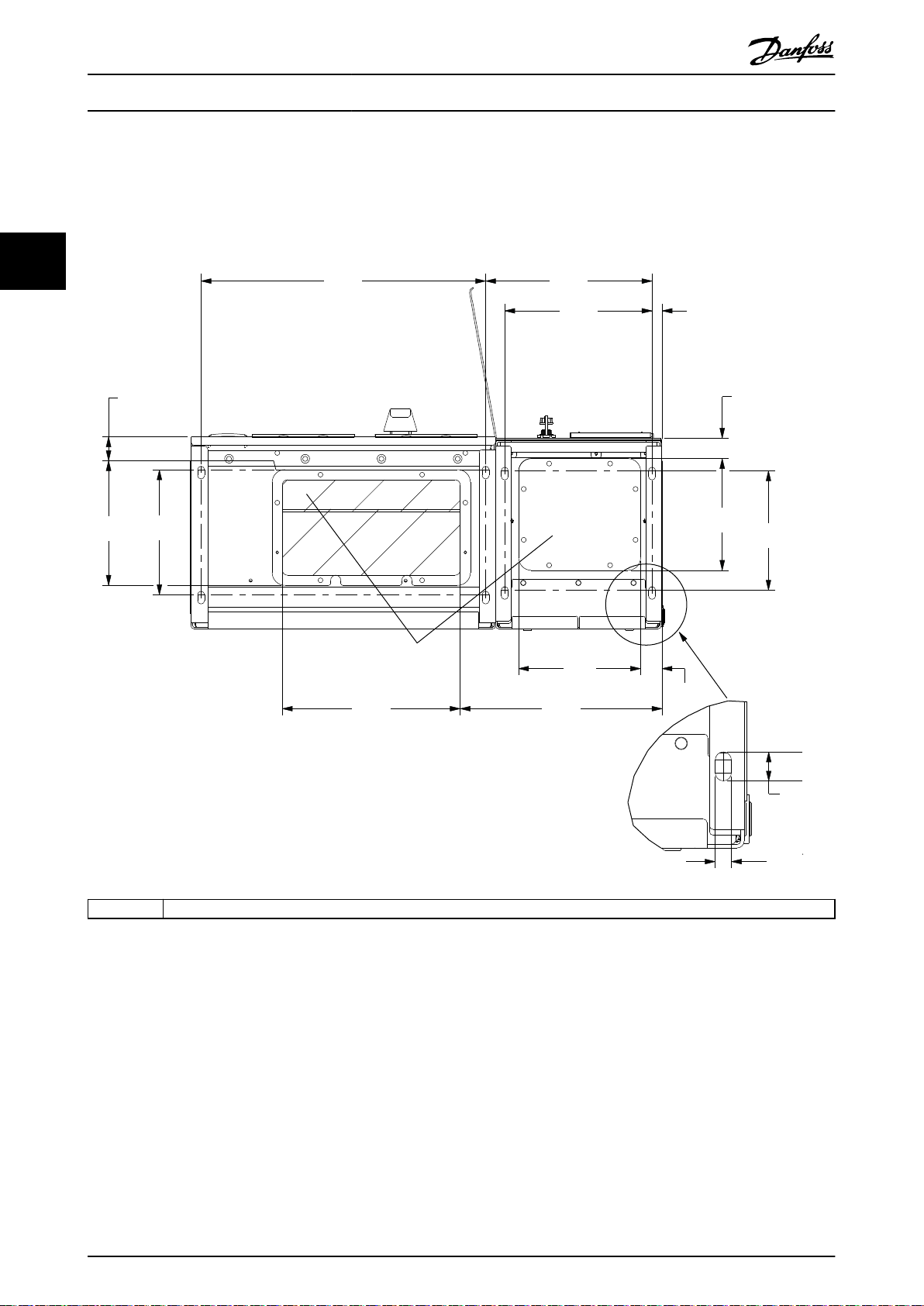
3.3.6 Terminal Locations for Enclsoure Size F18
Consider the position of the terminals when designing the cable access.
F-frame units have 4 interlocked cabinets:
Input options cabinet (not optional for LHD)
•
Filter cabinet
•
Rectier cabinet
•
Inverter cabinet
•
See chapter 1.3.3 Exploded View Drawings for exploded views of each cabinet. Mains inputs are located in the input option
cabinet, which conducts power to the rectier via interconnecting bus bars. Output from the unit is from the inverter
cabinet. No connection terminals are located in the rectier cabinet. Interconnecting bus bars are not shown.
3 3
1 Right side cut-away 3 Left side cut-away
2 Front view 4 Ground bar
Illustration 3.16 Input Option Cabinet, Enclosure Size F18 - Fuses Only
The gland plate is 42 mm below the 0 level. Shown are the left side view, front, and right.
MG37A302 Danfoss A/S © Rev. 04/2015 All rights reserved. 33
Page 38

0.0 [0.00]
134.6 [5.30]
104.3 [4.11]
0.0 [0.00]
179.3 [7.06]
219.6 [8.65]
294.6 [11.60]
334.8 [13.18]
409.8 [16.14]
436.9 [17.20]
0.0 [0.00]
532.9 [20.98]
0.0 [0.00]
44.4 [1.75]
244.4 [9.62]
154.0 [6.06]
344.0 [13.54]
1
234
5
130BA852.11
Mechanical Installation
VLT® AutomationDrive FC 302 Low Harmonic Drive
132-630 kW
33
500 kW1)(mm [in.]) 560–710 kW1)(mm [in.])
1 Ground bar
2 34.9 [1.4] 46.3 [1.8]
3 86.9 [3.4] 98.3 [3.9]
4 122.2 [4.8] 119 [4.7]
5 174.2 [6.9] 171 [6.7]
1) Disconnect location and related dimensions vary with kilowatt rating.
Illustration 3.17 Input Option Cabinet with Circuit Breaker, Enclosure Size F18
The gland plate is 42 mm below the 0 level. Shown are the left side view, front, and right.
34 Danfoss A/S © Rev. 04/2015 All rights reserved. MG37A302
Page 39

130BA849.13
.0 [.0]
54.4[2.1]
169.4 [6.7]
284.4 [11.2]
407.3 [16.0]
522.3 [20.6]
637.3 [25.1]
287.4 [11.3]
253.1 [10.0]
.0 [.0]
.0 [.0]
339.4 [13.4]
287.4 [11.3]
.0 [.0]
339.4 [13.4]
308.3 [12.1]
465.6 [18.3]
465.6 [18.3]
198.1[7.8]
234.1 [9.2]
282.1 [11.1]
318.1 [12.5]
551.0 [21.7]
587.0 [23.1]
635.0 [25.0]
671.0 [26.4]
44.40 [1.75]
244.40 [9.62]
204.1 [8.0]
497.1
[19.6]
572.1
[22.5]
180.3 [7.1]
129.1 [5.1]
1
2
3
Mechanical Installation Operating Instructions
3 3
1 Front view
2 Left side view
3 Right side view
Illustration 3.18 Inverter Cabinet, Enclosure Size F18
The gland plate is 42 mm below the 0 level. Shown are the left side view, front, and right.
Torque
3.3.7
Correct torque is imperative for all electrical connections.
The correct values are listed in Table 3.2. Incorrect torque
results in a bad electrical connection. Use a torque wrench
to ensure correct torque.
Enclosure
size
Terminal Torque [Nm] (in-
Mains
Motor
D
Regen
Brake
Mains
Motor
Regen
E
Brake
lbs)
19–40
(168–354)
8.5–20.5
(75–181)
19–40
(168–354)
8.5–20.5
(75–181)
Bolt size
M10
M8
M10
M8
Enclosure
size
Table 3.2 Torque for Terminals
Terminal Torque [Nm] (in-
Mains
Motor
F
Brake
Regen
lbs)
19–40
(168–354)
8.5–20.5
(75–181)
8.5–20.5
(75–181)
Bolt size
M10
M8
M8
MG37A302 Danfoss A/S © Rev. 04/2015 All rights reserved. 35
Page 40

Electrical Installation
4 Electrical Installation
VLT® AutomationDrive FC 302 Low Harmonic Drive
132-630 kW
4.1 Safety Instructions
See chapter 2 Safety for general safety instructions.
WARNING
44
INDUCED VOLTAGE
Induced voltage from output motor cables that run
together can charge equipment capacitors, even with the
equipment turned o and locked out. Failure to run
output motor cables separately or use screened cables
could result in death or serious injury.
Run output motor cables separately, or
•
Use screened cables.
•
CAUTION
SHOCK HAZARD
The frequency converter can cause a DC current in the
PE conductor. Failure to follow the recommendation
means that the RCD may not provide the intended
protection.
When a residual current-operated protective
•
device (RCD) is used for protection against
electrical shock, only an RCD of Type B is
permitted on the supply side.
Overcurrent protection
Extra protective equipment, such as short-circuit
•
protection or motor thermal protection between
frequency converter and motor, is required for
applications with multiple motors.
Input fusing is required to provide short-circuit
•
and overcurrent protection. If not factorysupplied, the installer must provide fuses. See
maximum fuse ratings in chapter 8.4 Fuses.
Wire type and ratings
All wiring must comply with local and national
•
regulations regarding cross-section and ambient
temperature requirements.
Power connection wire recommendation:
•
Minimum 75 °C rated copper wire.
See and chapter 8.3 General Technical Data for
recommended wire sizes and types.
36 Danfoss A/S © Rev. 04/2015 All rights reserved. MG37A302
Page 41

1
2
2
3
3
4
5
3
2
5
6
3
7
8
6
8
9
7
9
10
130BC644.10
Electrical Installation Operating Instructions
4.2 Electromagnetic Compatability (EMC)
To obtain an EMC-compliant installation, follow the
instructions provided in chapter 4.4 Grounding,
chapter 4.3 Power Connections, chapter 4.6 Motor
Connection, and chapter 4.8 Control Wiring.
4.2.1 EMC Interference
4 4
1 Customer control termination points–options A and B 6 Motor output cable, 3-phase and PE (not screened)
2 Screened control wiring 7 Cable gland
3 Cable clamp 8 Clearance, minimum 200 mm
4 Customer control input 9 Mains input cable, 3-phase and reinforce PE (not screened)
5
Potential equialisation wire [minimum 16 mm2]
Illustration 4.1 EMC-correct Installation
10 Low harmonic drive (LHD)
NOTICE
EMC Interference
Use screened cables for motor and control wiring. Separate the LHD mains input cable, motor cable, and control wiring.
Minimum 200 mm (7.9 in) clearance between power, motor, and control cables is required. Maximise this clearance to
minimise EMC emissions. This reduces the risk of interference between the LHD and other electronic devices.
MG37A302 Danfoss A/S © Rev. 04/2015 All rights reserved. 37
Page 42

3 Phase
power
input
130BA026.10
91 (L1)
92 (L2)
93 (L3)
95 PE
U
1
V
1
W
1
175ZA114.11
96 97 98
96 97 98
FC
FC
Motor
Motor
U
2
V
2
W
2
U
1
V
1
W
1
U
2
V
2
W
2
Electrical Installation
VLT® AutomationDrive FC 302 Low Harmonic Drive
132-630 kW
4.3 Power Connections
Make the screen connections with the largest possible
surface area (cable clamp). Use the installation devices
NOTICE
Cables, general information
All cabling must comply with national and local
regulations on cable cross-sections and ambient
temperature. UL applications require 75 °C copper
conductors. For non-UL applications, 75 and 90 °C
copper conductors are thermally acceptable.
44
The power cable connections are located as shown in
Illustration 4.2. Dimension cable cross-section in accordance
within the frequency converter.
Cable-length and cross-section
The frequency converter has been EMC-tested with a given
cable length. To reduce the noise level and leakage
currents, keep the motor cable as short as possible.
Switching frequency
When frequency converters are used with sine-wave lters
to reduce the acoustic noise from a motor, set the
switching frequency according to
parameter 14-01 Switching Frequency.
with the current ratings and local legislation. See
Termi
chapter 8.3.1 Cable lengths and cross-sections for details.
For protection of the frequency converter, use the
recommended fuses if there are no built-in fuses. Fuse
recommendations are provided in chapter 8.4 Fuses. Ensure
that proper fusing is made according to local regulation.
If included, the mains connection is
tted to the mains
switch.
96 97 98 99
nal
numb
er
Motor voltage 0–100% of mains
U V W
U1 V1 W1
W2 U2 V2 6 wires out of motor
U1 V1 W1
1)
voltage.
PE
3 wires out of motor
Delta-connected
1)
PE
Star-connected U2, V2, W2
1)
U2, V2, and W2 to be interconnected
PE
separately.
NOTICE
To comply with EMC emission specications, screened/
armoured cables are recommended. If an unscreened/
unarmoured cable is used, see chapter 4.7.3 Power and
Control Wiring for Unscreened Cables.
See chapter 8 Specications for correct dimensioning of
motor cable cross-section and length.
Screening of cables
Avoid installation with twisted screen ends (pigtails). They
spoil the screening eect at higher frequencies. If breaking
the screen is necessary to install a motor isolator or
contactor, continue the screen at the lowest possible HF
impedance.
Connect the motor cable screen to both the de-coupling
plate of the frequency converter and to the metal housing
of the motor.
38 Danfoss A/S © Rev. 04/2015 All rights reserved. MG37A302
Illustration 4.2 Power Cable Connections
Table 4.1 Terminal Connections
1) Protective earth connection
Illustration 4.3 Y and Delta Terminal Congurations
4.4 Grounding
WARNING
GROUNDING HAZARD!
For operator safety, it is important to ground the
frequency converter properly in accordance with national
and local electrical codes as well as instructions
contained within this document. Do not use conduit
connected to the frequency converter as a replacement
for proper grounding. Ground currents are higher than
3.5 mA. Failure to ground the frequency converter
properly could result in death or serious injury.
Page 43

Electrical Installation
Operating Instructions
NOTICE
It is the responsibility of the user or certied electrical
installer to ensure correct grounding of the equipment in
accordance with national and local electrical codes and
standards.
Follow all local and national electrical codes to
•
ground electrical equipment properly.
Establish proper protective earthing for
•
equipment with ground currents higher than 3.5
mA, see chapter 4.4.1 Leakage Current (>3.5 mA).
A dedicated ground wire is required for input
•
power, motor power, and control wiring.
Use the clamps provided with the equipment for
•
proper ground connections.
Do not ground one frequency converter to
•
another in a “daisy chain” fashion.
Keep the ground wire connections as short as
•
possible.
Using high-strand wire to reduce electrical noise
•
is recommended.
Follow motor manufacturer wiring requirements.
•
Leakage Current (>3.5 mA)
4.4.1
Follow national and local codes regarding protective
earthing of equipment with a leakage current >3.5 mA.
Frequency converter technology implies high frequency
switching at high power. This generates a leakage current
in the ground connection. A fault current in the frequency
converter at the output power terminals might contain a
DC component, which can charge the lter capacitors and
cause a transient ground current. The earth leakage
current depends on various system congurations
including RFI ltering, screened motor cables, and
frequency converter power.
In the case of a ground fault, a DC component develops in
the fault current.
If using ELCB relays, observe local regulations. Relays must
be suitable for protection of 3-phase equipment with a
bridge rectier and for a brief discharge on power-up.
4.5.2 RFI Switch
Mains supply isolated from ground
If the frequency converter is supplied from an isolated
mains source or TT/TN-S mains with grounded leg, turn o
the RFI switch via parameter 14-50 RFI Filter on both
frequency converter and the lter. For further reference,
see IEC 364-3. When optimum EMC performance is needed,
parallel motors are connected, or the motor cable length is
above 25 m, set parameter 14-50 RFI Filter to [ON].
In OFF, the internal RFI capacitors (lter capacitors)
between the enclosure and the DC link are cut o to avoid
damage to the intermediate circuit and reduce ground
capacity currents (IEC 61800-3).
Refer to the application note VLT on IT mains. It is
important to use isolation monitors that work together
with power electronics (IEC 61557-8).
Screened Cables
4.5.3
It is important to connect screened cables properly to
ensure high EMC immunity and low emissions.
Connection can be made using either cable glands or
clamps:
EMC cable glands: Generally available cable
•
glands can be used to ensure an optimum EMC
connection.
EMC cable clamp: Clamps allowing easy
•
connection are supplied with the unit.
4.6
Motor Connection
4 4
EN/IEC61800-5-1 (Power Drive System Product Standard)
requires special care if the leakage current exceeds 3.5 mA.
Grounding must be reinforced in 1 of the following ways:
Ground wire of at least 10 mm2.
•
2 separate ground wires both complying with the
•
dimensioning rules.
See EN 60364-5-54 § 543.7 for further information.
4.5
Input Options
4.5.1 Extra Protection (RCD)
ELCB relays, multiple protective grounding, or standard
grounding provide extra protection, if local safety
regulations are followed.
MG37A302 Danfoss A/S © Rev. 04/2015 All rights reserved. 39
4.6.1 Motor Cable
Connect the motor to terminals U/T1/96, V/T2/97, W/T3/98,
on the far right of the unit. Ground to terminal 99. All
types of 3-phase asynchronous standard motors can be
used with a frequency converter. The factory setting is for
clockwise rotation with the frequency converter output
connected as follows:
Terminal number Function
96, 97, 98 Mains U/T1, V/T2, W/T3
99 Ground
Table 4.2 Terminal Functions
Page 44

175HA036.11
U
1
V
1
W
1
96 97 98
FC
Motor
U
2
V
2
W
2
U
1
V
1
W
1
96 97 98
FC
Motor
U
2
V
2
W
2
Electrical Installation
Terminal U/T1/96 connected to U-phase.
•
Terminal V/T2/97 connected to V-phase.
•
Terminal W/T3/98 connected to W-phase.
•
VLT® AutomationDrive FC 302 Low Harmonic Drive
132-630 kW
The direction of rotation can be changed by switching 2
phases in the motor cable or by changing the setting of
parameter 4-10 Motor Speed Direction.
NOTICE
If a retrot application requires an unequal number of
wires per phase, consult the factory or use the top/
bottom entry side cabinet option instruction.
4.6.2 Brake Cable
Motor rotation check can be performed via
44
parameter 1-28 Motor Rotation Check and following the
Frequency converters with factory installed brake chopper
option.
steps shown in the display.
(Only standard with letter B in position 18 in the type
code).
The connection cable to the brake resistor must be
screened and the maximum length from frequency
converter to the DC bar is limited to 25 m.
Terminal number Function
81, 82 Brake resistor terminals
Table 4.3 Terminal Functions
The connection cable to the brake resistor must be
screened. Connect the screen with cable clamps to the
conductive back plate of the frequency converter and the
metal cabinet of the brake resistor.
Size the brake cable cross-section to match the brake
torque.
WARNING
Note that voltages up to 790 V DC, depending on the
supply voltage, are possible on the terminals.
Illustration 4.4 Motor Rotation Check
F-frame requirements
Use motor phase cables in quantities of 2, resulting in 2, 4,
6, or 8 to obtain an equal number of wires on both
inverter module terminals. The cables are required to be
equal length within 10% between the inverter module
terminals and the
recommended common point is the motor terminals.
Output junction box requirements
The length, minimum 2.5 m, and quantity of cables must
be equal from each inverter module to the common
terminal in the junction box.
40 Danfoss A/S © Rev. 04/2015 All rights reserved. MG37A302
F-frame requirements
Connect the brake resistors to the brake terminals in each
inverter module.
Motor Insulation
4.6.3
For motor cable lengths ≤ the maximum cable length, the
motor insulation ratings listed in Table 4.4 are
recommended. The peak voltage can be twice the DC-link
voltage or 2.8 times mains voltage, due to transmission
line eects in the motor cable. If a motor has lower
insulation rating, use a dU/dt or sine wave lter.
rst common point of a phase. The
Nominal mains voltage Motor insulation
UN≤420 V
420 V<UN≤500 V Reinforced ULL=1600 V
Table 4.4 Recommended Motor Insulation Ratings
Standard ULL=1300 V
Page 45

Electrical Installation
Operating Instructions
4.6.4 Motor Bearing Currents
Motors with a rating of 110 kW or higher combined with
frequency converters are best with NDE (non-drive end)
insulated bearings to eliminate circulating bearing currents
caused by motor size. To minimise DE (drive end) bearing
and shaft currents, proper grounding is required for:
The frequency converter.
•
The motor.
•
Motor-driven machine.
•
Motor to the driven machine.
•
Although failure due to bearing currents is infrequent, use
the following strategies to reduce the likelihood:
Use an insulated bearing.
•
Apply rigorous installation procedures.
•
Ensure that the motor and load motor are
•
aligned.
Strictly follow the EMC Installation guideline.
•
Reinforce the PE so the high frequency
•
impedance is lower in the PE than the input
power leads.
Provide a good high frequency connection
•
between the motor and the frequency converter.
Ensure that the impedance from frequency
•
converter to building ground is lower than the
grounding impedance of the machine. Make a
direct ground connection between the motor and
load motor.
Apply conductive lubrication.
•
Balance the line voltage to ground.
•
Use an insulated bearing as recommended by the
•
motor manufacturer.
NOTICE
Motors from reputable manufacturers typically have
insulated bearings as standard in motors of this size.
If necessary, and after consultation with Danfoss:
Lower the IGBT switching frequency.
•
Modify the inverter waveform, 60° AVM vs.
•
SFAVM.
Install a shaft grounding system or use an
•
isolating coupling between motor and load.
Use minimum speed settings if possible.
•
Use a dU/dt or sine-wave lter.
•
4.7
AC Mains Connection
4.7.1 Mains Connection
Connect mains to terminals 91, 92, and 93 on the far left
of the unit. Ground is connected to the terminal on the
right of terminal 93.
Terminal
number
91, 92, 93 Mains R/L1, S/L2, T/L3
94 Ground
Table 4.5 Terminal Functions
Ensure sucient current supply to the frequency converter.
If the unit is without built-in fuses, ensure that the
appropriate fuses have the correct current rating.
External Fan Supply
4.7.2
Function
NOTICE
Applicable for E and F enclosures only.
If the frequency converter is supplied by DC, or the fan
must run independently of the supply, use an external
supply. Make the connection on the power card.
Terminal
number
100, 101 Auxiliary supply S, T
102, 103 Internal supply S, T
Table 4.6 Terminal Functions
The connector on the power card provides the connection
of line voltage for the cooling fans. The fans are connected
from the factory to be supplied from a common AC line
(jumpers between 100–102 and 101–103). If external
supply is needed, remove the jumpers and connect the
supply to terminals 100 and 101. Protect with a 5 A fuse.
In UL applications, use a LittelFuse KLK-5 or equivalent.
Function
4 4
MG37A302 Danfoss A/S © Rev. 04/2015 All rights reserved. 41
Page 46

Motor
Line Power
Stop
Start
Speed
Control
130BX370.10
Electrical Installation
VLT® AutomationDrive FC 302 Low Harmonic Drive
132-630 kW
4.7.3 Power and Control Wiring for
Unscreened Cables
WARNING
INDUCED VOLTAGE
Induced voltage from coupled output motor cables
charges equipment capacitors even with the equipment
turned o and locked out. Run motor cables from
44
multiple frequency converters separately. Failure to run
output cables separately could result in death or serious
injury.
CAUTION
COMPROMISED PERFORMANCE
The frequency converter runs less eciently if wiring is
not isolated properly. To isolate high frequency noise,
place the following in separate metallic conduits:
Power wiring
•
Motor wiring
•
Control wiring
•
Failure to isolate these connections could result in less
than optimum controller and associated equipment
performance.
Because the power wiring carries high-frequency electrical
pulses, it is important to run input power and motor
power in separate conduit. If incoming power wiring is in
the same conduit as motor wiring, these pulses can couple
electrical noise back onto the power grid. Isolate control
wiring from high-voltage power wiring. See Illustration 4.5.
When screened/armoured cable is not used, at least 3
separate conduits are connected to the panel options
cabinet.
Mains Disconnects
4.7.4
Enclosure size Power and voltage Type
D 132–200 kW 380–500 V OT400U12-9 or ABB OETL-NF400A
E 250 kW 380–500 V ABB OETL-NF600A
E 315–400 kW 380–500 V ABB OETL-NF800A
F 450 kW 380–500 V Merlin Gerin NPJF36000S12AAYP
F 500–630 kW 380–500 V Merlin Gerin NRK36000S20AAYP
Table 4.7 Recommended Mains Disconnects
Illustration 4.5 Example of Proper Electrical Installation Using
Conduit
42 Danfoss A/S © Rev. 04/2015 All rights reserved. MG37A302
Page 47

130BE138.10
Electrical Installation Operating Instructions
4.7.5 F-FrameCircuit Breakers
Enclosure size Power and voltage Type
F 450 kW 380–500 V Merlin Gerin NPJF36120U31AABSCYP
F 500–630 kW 380–500 V Merlin Gerin NRJF36200U31AABSCYP
Table 4.8 Recommended Circuit Breakers
4.7.6 F-Frame Mains Contactors
Enclosure size Power and voltage Type
F 450–500kW 380–500 V Eaton XTCE650N22A
F 560–630kW380–500 V Eaton XTCEC14P22B
Table 4.9 Recommended Contactors
4.8 Control Wiring
4.8.1 Control Cable Routing
Tie down all control wires to the designated control cable
routing as shown in Illustration 4.6, Illustration 4.7,
Illustration 4.8, and Illustration 4.9. Remember to connect
the shields in a proper way to ensure optimum electrical
immunity.
4 4
Fieldbus connection
Connections are made to the relevant options on the
control card. For details, see the relevant
instruction. The cable must either be entered through the
access point in the top or be placed in the provided path
inside the frequency converter and tied down with other
control wires (see Illustration 4.6, Illustration 4.7, and
Illustration 4.8).
eldbus
Illustration 4.6 Control Card Wiring Path for Enclosure Size
D1n
MG37A302 Danfoss A/S © Rev. 04/2015 All rights reserved. 43
Page 48

130BE137.10
Electrical Installation
VLT® AutomationDrive FC 302 Low Harmonic Drive
132-630 kW
44
Illustration 4.7 Control Card Wiring Path for Enclosure Size
D2n
Illustration 4.8 Control Card Wiring Path for Enclosure Size E9
44 Danfoss A/S © Rev. 04/2015 All rights reserved. MG37A302
Page 49

130BB187.10
1
130BA150.10
9 - 10 mm
(0.37 in)
130BT312.10
Electrical Installation
Operating Instructions
Access to Control Terminals
4.8.2
All terminals for the control cables are located beneath the
LCP (both lter and frequency converter LCPs). They are
accessed by opening the door of the unit.
4.8.3 Electrical Installation, Control
Terminals
1 Routing path for the control card wiring inside the frequency
converter enclosure.
To connect the cable to the terminal:
1. Strip insulation by about 9–10 mm.
Illustration 4.10 Length to Strip the Insulation
2. Insert a screwdriver (maximum 0.4 x 2.5 mm) in
the square hole.
3. Insert the cable in the adjacent circular hole.
4 4
Illustration 4.9 Control Card Wiring Path for Enclosure Size F18
Illustration 4.11 Inserting the Cable in the Terminal Block
4. Remove the screwdriver. The cable is now
mounted in the terminal.
To remove the cable from the terminal:
1. Insert a screwdriver (maximum 0.4 x 2.5 mm) in
the square hole.
2. Pull out the cable.
MG37A302 Danfoss A/S © Rev. 04/2015 All rights reserved. 45
Page 50

130BT311.10
130BT306.10
Electrical Installation
VLT® AutomationDrive FC 302 Low Harmonic Drive
132-630 kW
44
Illustration 4.13 Control Terminal Locations
Illustration 4.12 Removing the Screwdriver after Cable
Insertion
46 Danfoss A/S © Rev. 04/2015 All rights reserved. MG37A302
Page 51

1
2
HI inductor Temperature
feed back
(NC)
91 (L1)
92 (L2)
93 (L3)
50 (+10 V OUT)
53 (A IN)
54 (A IN)
55 (COM A IN)
0/4-20 mA
12 (+24 V OUT)
13 (+24 V OUT)
18 (D IN)
20 (COM D IN)
15 mA
200 mA
(U) 96
(V) 97
(W) 98
(PE) 99
(COM A OUT) 39
(A OUT) 42
0/4-20 mA
03
+10 VDC
0 VDC - 10 VDC
0/4-20 mA
24 VDC
02
01
05
04
06
240 VAC, 2A
24 V (NPN)
0 V (PNP)
0 V (PNP)
24 V (NPN)
19 (D IN)
24 V (NPN)
0 V (PNP)
27
24 V
0 V
(D IN/OUT)
0 V (PNP)
24 V (NPN)
(D IN/OUT)
0 V
24 V
29
24 V (NPN)
0 V (PNP)
0 V (PNP)
24 V (NPN)
33 (D IN)
32 (D IN)
1 2 1 2
1 2
ON
A53 U-I (S201)
ON
A54 U-I (S202)
ON=0-20 mA
OFF=0-10 V
400 VAC, 2A
P 5-00
(R+) 82
(R-) 81
+ - + -
(P RS-485) 68
(N RS-485) 69
(COM RS-485) 61
0 V
5 V
S801
RS-485
RS-485
ON
S801/Bus Term.
OFF-ON
3 Phase
power
After HI inductor
Switch Mode
Power Supply
Motor
Analog Output
Interface
Relay1
Relay2
ON=Terminated
OFF=Open
Brake
resistor
(NPN) = Sink
(PNP) = Source
240 VAC, 2A
400 VAC, 2A (E & F
frame only)
0 VDC - 10 VDC
10 VDC
37 (D IN) - option
130BE195.10
Electrical Installation Operating Instructions
4.8.4 Electrical Installation, Control Cables
4 4
Illustration 4.14 Terminal Diagram for the Frequency Converter Side
MG37A302 Danfoss A/S © Rev. 04/2015 All rights reserved. 47
Page 52

Switch Mode
Power Supply
Analog Output
Interface
relay1
relay2
(PNP) = Source
(NPN) = Sink
ON=Terminated
OFF=Open
50 (+10 V OUT)
53 (A IN)
54 (A IN)
55 (COM A IN)
0/4-20 mA
12 (+24V OUT)
13 (+24V OUT)
18 (D IN)
20 (COM D IN)
10Vdc
15mA 130/200mA
+ - + -
(COM A OUT) 39
(A OUT) 42
(P RS-485) 68
(N RS-485) 69
(COM RS-485) 61
0V
5V
S801
0/4-20 mA
RS-485
RS-485
03
+10Vdc
-10Vdc -
+10Vdc
+10Vdc
0/4-20 mA
-10Vdc -
240Vac, 2A
24Vdc
02
01
05
04
06
240Vac, 2A
24V (NPN)
0V (PNP)
0V (PNP)
24V (NPN)
19 (D IN)
24V (NPN)
0V (PNP)
27
24V
0V
(D IN/OUT)
0V (PNP)
24V (NPN)
(D IN/OUT)
0V
24V
29
24V (NPN)
0V (PNP)
0V (PNP)
24V (NPN)
33 (D IN)
32 (D IN)
1 2
ON
S201
ON
21
S202
ON/I=0-20mA
OFF/U=0-10V
400Vac, 2A
P 5-00
21
ON
S801
*
Optional
RFI
Optional
Fuses
Optional
Manual
Disconnect
HI Reactor
L
m
L
m
L
m
L
ac
L
ac
L
ac
AC
Contactor
Relay 12
Control &
AUX
Feedback
Soft-Charge
Resistor
Converter Side
Filter
Power Stage
AF Current
Sensors
Capacitor
Current
Sensors
VLT Drive
Main’s
3
3
3
CTs
L
c
L
c
L
c
CefCefC
ef
RefRefR
ef
I
r
I
s
I
t
91 (L1)
92 (L2)
93 (L3)
Mains
380 to
500 VAC
130BE196.10
Electrical Installation
VLT® AutomationDrive FC 302 Low Harmonic Drive
132-630 kW
44
Illustration 4.15 Terminal Diagram for the Filter Side
48 Danfoss A/S © Rev. 04/2015 All rights reserved. MG37A302
Page 53

Electrical Installation Operating Instructions
4.8.5 Safe Torque O (STO)
To run STO, additional wiring for the frequency converter is
required. Refer to VLT® Frequency Converters Safe Torque O
Operating Instructions for further information.
4.9 Additional Connections
4.9.1 Serial Communication
RS485 is a 2-wire bus interface compatible with multi-drop
network topology, that is nodes can be connected as a
bus, or via drop cables from a common trunk line. A total
of 32 nodes can be connected to 1 network segment.
Repeaters divide networks.
NOTICE
Each repeater functions as a node within the segment in
which it is installed. Each node connected within a given
network must have a unique node address across all
segments.
Terminate each segment at both ends, using either the
termination switch (S801) of the frequency converters or a
biased termination resistor network. Always use screened
twisted pair (STP) cable for bus cabling, and always follow
good common installation practice.
Low-impedance ground connection of the screen at every
node is important, including at high frequencies. Thus,
connect a large surface of the screen to ground, for
example with a cable clamp or a conductive cable gland. It
may be necessary to apply potential-equalizing cables to
maintain the same ground potential throughout the
network, particularly in installations with long cables.
To prevent impedance mismatch, always use the same
type of cable throughout the entire network. When
connecting a motor to the frequency converters, always
use screened motor cable.
4.9.2
Mechanical Brake Control
In hoisting/lowering applications, it is necessary to be
able to control an electro-mechanical brake:
Control the brake using any relay output or
•
digital output (terminal 27 or 29).
Keep the output closed (voltage-free) as long as
•
the frequency converter is unable to support the
motor, due to the load being too heavy, for
example.
Select [32] Mechanical brake control in parameter
•
group 5-4* Relays for applications with an electromechanical brake.
The brake is released when the motor current
•
exceeds the preset value in
parameter 2-20 Release Brake Current.
The brake engages when the output frequency is
•
less than the frequency set in
parameter 2-21 Activate Brake Speed [RPM] or
parameter 2-22 Activate Brake Speed [Hz], only if
the frequency converter completes a stop
command.
If the frequency converter is in alarm mode or in an
overvoltage situation, the mechanical brake immediately
cuts in.
4 4
Cable
Impedance
Cable length
[m]
Table 4.10 Cable Recommendations
MG37A302 Danfoss A/S © Rev. 04/2015 All rights reserved. 49
Screened twisted pair (STP)
120 Ω
Maximum 1200 (including drop lines)
Maximum 500 station-to-station
Page 54

130BA170.11
LC lter
Electrical Installation
VLT® AutomationDrive FC 302 Low Harmonic Drive
132-630 kW
4.9.3 Parallel Connection of Motors
The frequency converter can control several parallelconnected motors. The total current consumption of the
motors must not exceed the rated output current I
the frequency converter.
M,N
for
NOTICE
44
Installations with cables connected in a common joint as
in Illustration 4.16 are only recommended for short cable
lengths.
NOTICE
When motors are connected in parallel,
parameter 1-29 Automatic Motor Adaptation (AMA) cannot
be used.
NOTICE
The electronic thermal relay (ETR) of the frequency
converter cannot be used as motor protection for the
individual motor in systems with parallel-connected
motors. Provide further motor protection with
thermistors in each motor or individual thermal relays.
Circuit breakers are not suitable as protection.
Problems are possible at start and at low RPM values if
motor sizes vary widely. The relatively high ohmic
resistance in the stator of small motors calls for a higher
voltage at start and at low RPM values.
4.9.4 Motor Thermal Protection
The electronic thermal relay in the frequency converter has
received UL-approval for single motor protection, when
parameter 1-90 Motor Thermal Protection is set for [4] ETR
Trip 1 and parameter 1-24 Motor Current is set to the rated
motor current (see motor nameplate).
For the North American market: The ETR functions provide
class 20 motor overload protection in accordance with
NEC.
For motor thermal protection, it is also possible to use the
VLT® PTC Thermistor Card MCB 112. This card provides
ATEX
certication to protect motors in explosion hazardous
areas, Zone 1/21 and Zone 2/22. When
parameter 1-90 Motor Thermal Protection is set to [20] ATEX
ETR and MCB 112 are combined, it is possible to control an
Ex-e motor in explosion hazardous areas. Consult the
Programming Guide for details on how to set up the
frequency converter for safe operation of Ex-e motors.
Illustration 4.16 Installations with Cables Connected in a
Common Joint
Voltage/Current Input Selection
4.9.5
(Switches)
The analog mains terminals 53 and 54 allow setting of
input signal to voltage (0–10 V) or current (0/4–20 mA).
See Illustration 4.14 and Illustration 4.15 for the location of
the control terminals within the low harmonic drive.
Default parameter settings:
Terminal 53: Speed reference signal in open loop
•
(see parameter 16-61 Terminal 53 Switch Setting).
Terminal 54: Feedback signal in closed loop (see
•
parameter 16-63 Terminal 54 Switch Setting).
NOTICE
REMOVE POWER
Remove power to the low harmonic drive before
changing switch positions.
1.
Remove the LCP (see Illustration 4.17).
2. Remove any optional equipment covering the
switches.
3. Set switches A53 and A54 to select the signal
type. U selects voltage, I selects current.
50 Danfoss A/S © Rev. 04/2015 All rights reserved. MG37A302
Page 55

130BE063.10
1
2
3
1
2
N O
3~ MOTOR NR. 1827421 2003
S/E005A9
1,5 KW
n 31,5 /min. 400 Y V
n 1400 /min. 50 Hz
COS 0,80 3,6 A
1,7L
B IP 65 H1/1A
BAUER D-7 3734 ESLINGEN
130BT307.10
Electrical Installation
1 Bus termination switch
2 A54 switch
3 A53 switch
Operating Instructions
4 4
Illustration 4.17 Bus Termination Switch, A53, and A54 Switch
Locations
4.10
Final Set-up and Test
Before operating the frequency converter, perform a nal
test of the installation:
1. Locate the motor name plate to nd out whether
the motor is star- (Y) or delta- connected (Δ).
2. Enter the motor name plate data in the
parameter list. Access the list by pressing the
[Quick Menu] key and selecting Q2 Quick Set-up.
See Table 4.11.
1.
2.
3.
4.
5.
Table 4.11 Quick Set-up Parameters
Parameter 1-20 Motor Power [kW ]
Parameter 1-21 Motor Power [HP]
Parameter 1-22 Motor Voltage
Parameter 1-23 Motor Frequency
Parameter 1-24 Motor Current
Parameter 1-25 Motor Nominal Speed
Illustration 4.18 Motor Name Plate
3. Perform an automatic motor adaptation (AMA) to
ensure optimum performance.
3a Connect terminal 27 to terminal 12 or
set parameter 5-12 Terminal 27 Digital
Input to [0] No operation.
3b Activate the AMA in
parameter 1-29 Automatic Motor
Adaptation (AMA).
3c Select either complete or reduced AMA.
If an LC
lter is mounted, run only the
reduced AMA, or remove the LC lter
during the AMA procedure.
3d
Press [OK]. The display shows Press
[Hand On] to start.
3e Press [Hand On]. A progress bar
indicates whether the AMA is in
progress.
3f Press
[O] - the frequency converter
enters alarm mode and the display
shows that the user terminated AMA.
MG37A302 Danfoss A/S © Rev. 04/2015 All rights reserved. 51
Page 56

Electrical Installation
VLT® AutomationDrive FC 302 Low Harmonic Drive
132-630 kW
Stop the AMA during operation
Successful AMA
The display shows Press [OK] to nish AMA.
•
Press [OK] to exit the AMA state.
•
Unsuccessful AMA
The frequency converter enters into alarm mode.
•
A description of the alarm can be found in
chapter 7 Diagnostics and Troubleshooting.
44
Report value in the alarm log shows the last
•
measuring sequence carried out by the AMA
before the frequency converter entered alarm
mode. This number, along with the description of
the alarm, helps with troubleshooting. Mention
the number and alarm description when
contacting Danfoss service personnel.
Unsuccessful AMA is the result of incorrectly registered
motor nameplate data or too large a
the motor power size and the frequency converter power
size.
Set up the desired limits for speed and ramp time
Minimum reference
Maximum reference
Table 4.12 Reference Parameters
Motor speed low limit
Motor speed high limit
Table 4.13 Speed Limits
Ramp-up time 1 [s]
Ramp-down time 1 [s]
Table 4.14 Ramp Times
4.11
F-frame Options
Space heaters and thermostat
There are space heaters mounted on the cabinet interior of
F-frame frequency converters. These heaters are controlled
by an automatic thermostat and help control humidity
inside the enclosure. The thermostat default settings turn
on the heaters at 10 °C (50 °F) and turn them o at 15.6
°C (60 °F).
dierence between
Parameter 3-02 Minimum
Reference
Parameter 3-03 Maximum
Reference
Parameter 4-11 Motor Speed Low
Limit [RPM] or
parameter 4-12 Motor Speed Low
Limit [Hz]
Parameter 4-13 Motor Speed
High Limit [RPM] or
parameter 4-14 Motor Speed
High Limit [Hz]
Parameter 3-41 Ramp 1 Ramp
Up Time
Parameter 3-42 Ramp 1 Ramp
Down Time
Cabinet light with power outlet
A light mounted on the cabinet interior of F-frame
frequency converters increases visibility during servicing
and maintenance. The housing includes a power outlet for
temporarily powering tools or other devices, available in 2
voltages:
230 V, 50 Hz, 2.5 A, CE/ENEC
•
120 V, 60 Hz, 5 A, UL/cUL
•
Transformer tap set-up
If the cabinet light, outlet, and/or the space heaters, and
thermostat are installed, transformer T1 requires its taps to
be set to the proper input voltage. A 380–480/500 V
frequency converter is initially set to the 525 V tap to
ensure that no overvoltage of secondary equipment occurs
if the tap is not changed before applying power. See
Table 4.15 to set the proper tap at terminal T1 located in
the rectier cabinet.
Input voltage range [V] Tap to select [V]
380–440 400
441–500 460
Table 4.15 Transformer Tap Set-up
NAMUR terminals
NAMUR is an international association of automation
technology users in the process industries, primarily
chemical and pharmaceutical industries in Germany.
Selecting this option, provides terminals organised and
labeled to the
frequency converters input and output terminals. This
requires VLT® PTC Thermistor Card MCB 112 and VLT
Extended Relay Card MCB 113.
RCD (residual current device)
Uses the core balance method to monitor ground fault
currents in grounded and high-resistance grounded
systems (TN and TT systems in IEC terminology). There is a
pre-warning (50% of main alarm set-point) and a main
alarm set-point. Associated with each set-point is an SPDT
alarm relay for external use. Requires an external windowtype current transformer (supplied and installed by the
customer).
•
•
•
•
•
Insulation resistance monitor (IRM)
Monitors the insulation resistance in ungrounded systems
(IT systems in IEC terminology) between the system phase
conductors and ground. There is an ohmic pre-warning
and a main alarm setpoint for the insulation level. An SPDT
specications of the NAMUR standard for
®
Integrated into the frequency converter safe
torque o circuit.
IEC 60755 Type B device monitors AC, pulsed DC,
and pure DC ground fault currents.
LED bar graph indicator of the ground fault
current level from 10–100% of the setpoint.
Fault memory.
TEST/RESET key.
52 Danfoss A/S © Rev. 04/2015 All rights reserved. MG37A302
Page 57

Electrical Installation Operating Instructions
alarm relay for external use is associated with each
setpoint.
NOTICE
Only 1 insulation resistance monitor can be connected to
each ungrounded (IT) system.
Integrated into the frequency converter Safe
•
Torque
O circuit.
LCD display of the ohmic value of the insulation
•
resistance.
Fault memory.
•
INFO, TEST, and RESET keys.
•
IEC emergency stop with Pilz safety relay
Includes a redundant 4-wire emergency-stop push button
mounted on the front of the enclosure and a Pilz relay that
monitors it in conjunction with the frequency converter
STO (Safe Torque O) circuit and the mains contactor
located in the options cabinet.
Manual motor starters
Provide 3-phase power for electric blowers often required
for larger motors. Power for the starters is provided from
the load side of any supplied contactor, circuit breaker, or
disconnect switch. Power is fused before each motor
starter, and is o when the incoming power to the
frequency converters is o. Up to 2 starters are allowed (1
if a 30 A, fuse-protected circuit is ordered), and are
integrated into the frequency converter STO circuit.
Unit features include:
Operation switch (on/o).
•
Short-circuit and overload protection with test
•
function.
Manual reset function.
•
30 A, fuse-protected terminals
3-phase power matching incoming mains voltage
•
for powering auxiliary customer equipment.
Not available if 2 manual motor starters are
•
selected.
Terminals are
•
the frequency converter is o.
Power for the fused protected terminals is
•
provided from the load side of any supplied
contactor, circuit breaker, or disconnect switch.
In applications where the motor is used as a brake, energy
is generated in the motor and sent back into the
frequency converter. If the energy cannot be transported
back to the motor, it increases the voltage in the frequency
converter DC line. In applications with frequent braking
and/or high inertia loads, this increase may lead to an
overvoltage trip in the frequency converter and
shut down. Brake resistors are used to dissipate the excess
energy resulting from the regenerative braking. The resistor
o when the incoming power to
nally a
is selected based on its ohmic value, its power dissipation
rate, and its physical size. Danfoss oers a wide variety of
dierent resistors that are specically designed for Danfoss
frequency converters.
4 4
MG37A302 Danfoss A/S © Rev. 04/2015 All rights reserved. 53
Page 58

Commissioning
5 Commissioning
VLT® AutomationDrive FC 302 Low Harmonic Drive
132-630 kW
5.1 Safety Instructions
See chapter 2 Safety for general safety instructions.
WARNING
HIGH VOLTAGE
Frequency converters contain high voltage when
55
connected to AC mains input power. Failure to perform
installation, start-up, and maintenance by qualied
personnel could result in death or serious injury.
Installation, start-up, and maintenance must be
•
performed by qualied personnel only.
Before applying power:
1. Close the cover properly.
2. Check that all cable glands are rmly tightened.
3. Ensure that input power to the unit is OFF and
locked out. Do not rely on the frequency
Pre-start
5.1.1
converter disconnect switches for input power
isolation.
4. Verify that there is no voltage on input terminals
L1 (91), L2 (92), and L3 (93), phase-to-phase, and
phase-to-ground.
5. Verify that there is no voltage on output
terminals 96 (U), 97 (V), and 98 (W), phase-tophase, and phase-to-ground.
6.
Conrm continuity of the motor by measuring Ω
values on U-V (96-97), V-W (97-98), and W-U
(98-96).
7. Check for proper grounding of the frequency
converter as well as the motor.
8. Inspect the frequency converter for loose
connections on the terminals.
9. Conrm that the supply voltage matches the
voltage of the frequency converter and the
motor.
CAUTION
Before applying power to the unit, inspect the entire installation as detailed in Table 5.1. Check mark those items when
completed.
Inspect for Description
Auxiliary equipment
Cable routing
Control wiring
Cooling clearance
EMC considerations
Environmental considerations
Look for auxiliary equipment, switches, disconnects, or input fuses/circuit breakers on the input
•
power side of the frequency converter or output side to the motor. Ensure that they are ready for
full speed operation.
Check function and installation of any sensors used for feedback to the frequency converter.
•
Remove power factor correction capacitors on motors, if present.
•
Use separate metallic conduits for each of the following:
•
-
-
-
Check for broken or damaged wires and loose connections.
•
Check that control wiring is isolated from power and motor wiring for noise immunity.
•
Check the voltage source of the signals.
•
Use screened or twisted pair cable. Ensure that the screen is terminated correctly.
•
Measure that top and bottom clearance is adequate to ensure proper air ow for cooling.
•
Check for proper installation regarding electromagnetic compatibility.
•
See equipment label for the maximum ambient operating temperature limits.
•
Humidity levels must be 5–95%, non-condensing.
•
☑
Input power
Motor wiring
Control wiring
54 Danfoss A/S © Rev. 04/2015 All rights reserved. MG37A302
Page 59

Commissioning Operating Instructions
Inspect for Description
Fusing and circuit
breakers
Grounding
Input and output power
wiring
Panel interior
Switches
Vibration
Table 5.1 Start-up Checklist
Check for proper fusing or circuit breakers.
•
Check that all fuses are inserted rmly and in operational condition, and that all circuit breakers are
•
in the open position.
The unit requires a ground wire from its enclosure to the building ground.
•
Check for good ground connections that are tight and free of oxidation.
•
Grounding to conduit or mounting the back panel to a metal surface is not sucient.
•
Check for loose connections.
•
Check that motor and mains are in separate conduit or separated screened cables.
•
Inspect that the unit interior is free of debris and corrosion.
•
Ensure that all switch and disconnect settings are in the proper positions.
•
Check that the unit is mounted solidly or that shock mounts are used as necessary.
•
Check for an unusual amount of vibration.
•
☑
5 5
MG37A302 Danfoss A/S © Rev. 04/2015 All rights reserved. 55
Page 60

130BD512.10
Auto
on
Reset
Hand
on
O
Status
Quick
Menu
Main
Menu
Alarm
Log
Back
Cancel
Info
OK
Status
1(1)
0.00 kW
O Remote Stop
0.0Hz
On
Alarm
Warn.
A
0.00 A
0.0 %
B
C
D
2605 kWh
1
2
3
4
5
6
7
8
9
10
11
12
13
14
15
16
17
18 19 20 21
Commissioning
5.2 Applying Power
VLT® AutomationDrive FC 302 Low Harmonic Drive
132-630 kW
Programme frequency converter and active lter
•
functions.
WARNING
HIGH VOLTAGE!
Frequency converters contain high voltage when
connected to AC mains. Installation, start-up, and
maintenance should be performed by qualied
personnel only. Failure to comply could result in death or
serious injury.
NOTICE
For commissioning via PC, install the MCT 10 Set-up
Software. The software is available for download (basic
version) or for ordering (advanced version, order number
130B1000). For more information and downloads, see
Manually reset the frequency converter or active
•
lter after a fault when auto-reset is inactive.
www.danfoss.com/BusinessAreas/DrivesSolutions/Software
55
UNINTENDED START!
When the frequency converter is connected to AC mains,
WARNING
+MCT10/MCT10+Downloads.htm.
5.3.2 LCP Layout
the motor may start at any time. The frequency
converter, motor, and any driven equipment must be in
operational readiness. Failure to comply could result in
The LCP is divided into 4 functional groups (see
Illustration 5.1).
death, serious injury, equipment, or property damage.
A. Display area
1. Conrm that the input voltage is balanced within
3%. If not, correct input voltage imbalance before
proceeding.
2. Ensure that optional equipment wiring, if present,
B. Display menu keys
C. Navigation keys and indicator lights (LEDs)
D. Operation keys and reset
matches the installation application.
3. Ensure that all operator devices are o. Panel
doors should be closed or cover mounted.
4. Apply power to the unit. Do not start the
frequency converter at this time. For units with a
disconnect switch, turn the switch on to apply
power.
NOTICE
If the status line at the bottom of the LCP reads AUTO
REMOTE COASTING or Alarm 60 External Interlock is
displayed, the unit is ready to operate but is missing an
input signal on terminal 27.
5.3 Local Control Panel Operation
5.3.1 Local Control Panel
The local control panel (LCP) is the combined display and
keypad on the front of the unit. The low harmonic drive
includes 2 LCPs: 1 to control the frequency converter side
and 1 to control the lter side.
The LCP has several functions:
Control speed of frequency converter when in
•
local mode.
Start and stop in local mode.
•
Display operational data, status, warnings, and
•
alarms.
56 Danfoss A/S © Rev. 04/2015 All rights reserved. MG37A302
Illustration 5.1 Local Control Panel (LCP)
A. Display area
The display area is activated when the frequency converter
receives power from mains voltage, a DC bus terminal, or
an external 24 V DC supply.
Page 61

Commissioning
Operating Instructions
The information displayed on the LCP can be customised
for user application. Select options in the Quick Menu
Q3-13 Display Settings.
Callout Display Parameter number Default setting
1 1.1 0-20 Reference %
2 1.2 0-21 Motor current
3 1.3 0-22 Power [kW]
4 2 0-23 Frequency
5 3 0-24 kWh counter
Table 5.2 Legend to Illustration 5.1, Display Area
(Frequency Converter Side)
B. Display menu keys
Menu keys are used for menu access for parameter set-up,
toggling through status display modes during normal
operation, and viewing fault log data.
Callout Key Function
6 Status Shows operational information.
7 Quick Menu Allows access to programming
parameters for initial set-up instructions
and many detailed application
instructions.
8 Main Menu Allows access to all programming
parameters.
9 Alarm Log Displays a list of current warnings, the
last 10 alarms, and the maintenance log.
Table 5.3 Legend to
Illustration 5.1, Display Menu Keys
C. Navigation keys and indicator lights (LEDs)
Navigation keys are used for programming functions and
moving the display cursor. The navigation keys also
provide speed control in local (hand) operation. There are
also 3 frequency converter status indicator lights in this
area.
Callout Indicator Light Function
15 ON Green The ON light activates when the
frequency converter receives
power from mains voltage, a DC
bus terminal, or an external 24 V
supply.
16 WARN Yellow When a warning is issued, the
yellow WARN light comes on
and text appears in the display
area identifying the problem.
17 ALARM Red A fault condition causes the red
alarm light to ash and an alarm
text is displayed.
Table 5.5 Legend to Illustration 5.1, Indicator Lights (LEDs)
D. Operation keys and reset
Operation keys are located at the bottom of the LCP.
Callout Key Function
18 Hand On Starts the frequency converter in local
control.
An external stop signal by control
•
input or serial communication
overrides the local hand on.
19 O Stops the operation but does not remove
power to the frequency converter.
20 Auto On Puts the system in remote operational
mode.
Responds to an external start
•
command by control terminals or
serial communication.
21 Reset Resets the frequency converter or active
lter manually after a fault has been
cleared.
Table 5.6 Legend to
Illustration 5.1, Operation Keys and Reset
5 5
Callout Key Function
10 Back Reverts to the previous step or list in the
menu structure.
11 Cancel Cancels the last change or command as
long as the display mode has not
changed.
12 Info Press for a denition of the function being
displayed.
13 Navigation
14 OK Press to access parameter groups or to
Table 5.4 Legend to Illustration 5.1, Navigation Keys
Press to move between items in the menu.
keys
enable an option.
NOTICE
The display contrast can be adjusted by pressing [Status]
and [▲]/[▼] keys.
5.3.3 Parameter Settings
Establishing the correct programming for applications
often requires setting functions in several related
parameters.
Programming data are stored internally in the frequency
converter.
For back-up, upload data into the LCP memory.
•
To download data to another frequency
•
converter, connect the LCP to that unit and
download the stored settings.
Restoring factory default settings does not
•
change data stored in the LCP memory.
MG37A302 Danfoss A/S © Rev. 04/2015 All rights reserved. 57
Page 62

Commissioning
VLT® AutomationDrive FC 302 Low Harmonic Drive
132-630 kW
5.3.4 Uploading/Downloading Data to/from
5.3.6
Restoring Default Settings
the LCP
NOTICE
1. Press [O] to stop operation before uploading or
downloading data.
2.
Press [Main Menu] parameter 0-50 LCP Copy and
press [OK].
3.
Select [1] All to LCP to upload data to the LCP or
select [2] All from LCP to download data from the
LCP.
4. Press [OK]. A progress bar shows the uploading or
55
5.3.5
Parameter settings can be accessed and changed from the
Quick Menu or from the Main Menu. The Quick Menu only
gives access to a limited number of parameters.
View changes
Quick Menu Q5 - Changes Made lists all parameters
changed from default settings.
downloading progress.
5. Press [Hand On] or [Auto On] to return to normal
operation.
Changing Parameter Settings
1. Press [Quick Menu] or [Main Menu] on the LCP.
2.
Press [▲] [▼] to browse through the parameter
groups, press [OK] to select a parameter group.
3.
Press [▲] [▼] to browse through the parameters,
press [OK] to select a parameter.
4.
Press [▲] [▼] to change the value of a parameter
setting.
5.
Press [◄] [►] to shift digit when a decimal
parameter is in the editing state.
6. Press [OK] to accept the change.
7.
Press either [Back] twice to enter Status, or press
[Main Menu] once to enter the Main Menu.
The list only shows parameters, which have been
•
changed in the current edit set-up.
Parameters, which have been reset to default
•
values, are not listed.
The message Empty indicates that no parameters
•
have been changed.
Risk of losing programming and monitoring records by
restoration of default settings. To provide a back-up,
upload data to the LCP before initialisation.
Restoring the default parameter settings is done by initialisation of the frequency converter. Initialisation is carried
out through parameter 14-22 Operation Mode
(recommended) or manually.
Initialisation using parameter 14-22 Operation
•
Mode does not reset frequency converter settings,
such as operating hours, serial communication
selections, personal menu settings, fault log,
alarm log, and other monitoring functions.
Manual initialisation erases all motor,
•
programming, localisation, and monitoring data,
and restores factory default settings.
Recommended initialisation procedure, via
parameter 14-22 Operation Mode
1. Press [Main Menu] twice to access parameters.
2.
Scroll to parameter 14-22 Operation Mode and
press [OK].
3.
Scroll to [2] Initialisation and press [OK].
4. Remove power to the unit and wait for the
display to turn o.
5. Apply power to the unit.
Default parameter settings are restored during start-up.
This may take slightly longer than normal.
6. Alarm 80 is displayed.
7. Press [Reset] to return to operation mode.
Manual initialisation procedure
1. Remove power to the unit and wait for the
display to turn o.
2. Press and hold [Status], [Main Menu], and [OK] at
the same time while applying power to the unit
(approximately 5 s or until audible click and fan
starts).
Factory default parameter settings are restored during
start-up. This may take slightly longer than normal.
Manual initialisation does not reset the following frequency
converter information:
Parameter 15-00 Operating hours
•
Parameter 15-03 Power Up's
•
Parameter 15-04 Over Temp's
•
Parameter 15-05 Over Volt's
•
58 Danfoss A/S © Rev. 04/2015 All rights reserved. MG37A302
Page 63

130BP066.10
1107 RPM
0 -
**
Operation/Display
1 -
**
Load/Motor
2 -
**
Brakes
3 -
**
Reference / Ramps
3.84 A 1 (1)
Main Menu
0-
**
Operation / Display
0.0%
0-0
*
Basic Settings
0-1
*
Set-up Operations
0-2
*
LCP Display
0-3
*
LCP Custom Readout
0.00A 1(1)
130BP087.10
0-0
*
Basic Settings
0.0%
0-03 Regional Settings
[0] International
0.00A 1(1)
130BP088.10
Commissioning
Operating Instructions
5.4 Basic Operational Programming
5.4.1
VLT® Low Harmonic Drive
Programming
The low harmonic drive includes 2 LCPs: 1 to control the
frequency converter side and 1 to control the lter side.
Because of this unique design, the detailed parameter
information for the product is found in 2 places.
Detailed programming information for the frequency
converter portion can be found in the relevant
programming guide. Detailed programming information for
the
lter can be found in the VLT® Active Filter AAF 006
Operating Instructions.
The remaining sections in this chapter apply to the
frequency converter side. The active lter of the low
harmonic drives is pre-congured for optimal performance
and must only be turned on by pressing its [Hand On] key
after the frequency converter side is commissioned.
Illustration 5.2 Main Menu
3. Press the navigation keys to scroll to parameter
group 0-0* Basic Settings and press [OK].
5 5
Commissioning with SmartStart
5.4.2
The SmartStart wizard enables fast conguration of basic
motor and application parameters.
SmartStart starts automatically at rst power-up
•
or after initialisation of the frequency converter.
Follow the on-screen instructions to complete the
•
commissioning of the frequency converter.
Always reactivate SmartStart by selecting Quick
Menu Q4 - SmartStart.
For commissioning without use of the SmartStart
•
wizard, refer to chapter 5.4.3 Commissioning via
[Main Menu] or the programming guide.
Illustration 5.3 Operation/Display
4. Press the navigation keys to scroll to
parameter 0-03 Regional Settings and press [OK].
NOTICE
Motor data is required for the SmartStart set-up. The
required data is normally available on the motor
nameplate.
5.4.3 Commissioning via [Main Menu]
Recommended parameter settings are intended for startup and check-out purposes. Application settings may vary.
Enter data with power ON, but before operating the
frequency converter.
1. Press [Main Menu] on the LCP.
2. Press the navigation keys to scroll to parameter
MG37A302 Danfoss A/S © Rev. 04/2015 All rights reserved. 59
group 0-** Operation/Display and press [OK].
Illustration 5.4 Basic Settings
5.
Press the navigation keys to select [0] Interna-
tional or [1] North America as appropriate and
press [OK]. (This changes the default settings for
a number of basic parameters).
6. Press [Main Menu] on the LCP.
7. Press the navigation keys to scroll to
parameter 0-01 Language.
8. Select the language and press [OK].
9. If a jumper wire is in place between control
terminals 12 and 27, leave
parameter 5-12 Terminal 27 Digital Input at factory
default. Otherwise, select No Operation in
parameter 5-12 Terminal 27 Digital Input.
Page 64

Commissioning
VLT® AutomationDrive FC 302 Low Harmonic Drive
132-630 kW
10. Make the application-specic settings in the
following parameters:
10a
Parameter 3-02 Minimum Reference.
10b
Parameter 3-03 Maximum Reference.
10c
Parameter 3-41 Ramp 1 Ramp Up Time.
10d
Parameter 3-42 Ramp 1 Ramp Down
Time.
10e
Parameter 3-13 Reference Site. Linked to
Hand/Auto Local Remote.
55
5.4.4 Asynchronous Motor Set-up
Enter the following motor data. The information can be
found on the motor nameplate.
1.
Parameter 1-20 Motor Power [kW] or
parameter 1-21 Motor Power [HP].
2.
Parameter 1-22 Motor Voltage.
3.
Parameter 1-23 Motor Frequency.
4.
Parameter 1-24 Motor Current.
5.
Parameter 1-25 Motor Nominal Speed.
When running in
ux mode, or for optimum performance
in VVC+ mode, extra motor data is required to set up the
following parameters. The data can be found in the motor
datasheet (this data is typically not available on the motor
nameplate). Run a complete AMA using
parameter 1-29 Automatic Motor Adaptation (AMA) [1]
Enable Complete AMA or enter the parameters manually.
Parameter 1-36 Iron Loss Resistance (Rfe) is always entered
manually.
1.
Parameter 1-30 Stator Resistance (Rs).
2.
Parameter 1-31 Rotor Resistance (Rr).
3.
Parameter 1-33 Stator Leakage Reactance (X1).
4.
Parameter 1-34 Rotor Leakage Reactance (X2).
5.
Parameter 1-35 Main Reactance (Xh).
6.
Parameter 1-36 Iron Loss Resistance (Rfe).
Application Settings
Low-inertia applications Keep calculated values.
High-inertia applications
High load at low speed
No-load application
Flux sensorless only
Table 5.7 Recommendations for Flux Applications
Permanent Magnet Motor Set-up
5.4.5
Parameter 1-66 Min. Current at Low
Speed.
Increase current to a value between
default and maximum depending on
the application.
Set ramp times matching the
application. Too fast ramp up causes
an overcurrent or overtorque. Too
fast ramp down causes an
overvoltage trip.
Parameter 1-66 Min. Current at Low
Speed.
Increase current to a value between
default and maximum depending on
the application.
Adjust parameter 1-18 Min. Current at
No Load to achieve smoother motor
operation by reducing torque ripple
and vibration.
Adjust parameter 1-53 Model Shift
Frequency.
Example 1: If the motor oscillates at
5 Hz and dynamics performance is
required at 15 Hz, set
parameter 1-53 Model Shift Frequency
to 10 Hz.
Example 2: If the application
involves dynamic load changes at
low speed, reduce
parameter 1-53 Model Shift Frequency.
Observe the motor behaviour to
make sure that the model shift
frequency is not reduced too much.
Symptoms of inappropriate model
shift frequency are motor oscillations
or frequency converter tripping.
Application-specic adjustment when running VVC
+
VVC+ is the most robust control mode. In most situations,
it provides optimum performance without further
NOTICE
Only use permanent magnet (PM) motor with fans and
pumps.
adjustments. Run a complete AMA for best performance.
Application-specic adjustment when running Flux
Flux mode is the preferred control mode for optimum
shaft performance in dynamic applications. Perform an
AMA since this control mode requires precise motor data.
Depending on the application, further adjustments may be
required.
Initial programming steps
1. Activate PM motor operation in
parameter 1-10 Motor Construction, select [1] PM,
non-salient SPM.
2.
Set parameter 0-02 Motor Speed Unit to [0] RPM.
See Table 5.7 for application-related recommendations.
60 Danfoss A/S © Rev. 04/2015 All rights reserved. MG37A302
Page 65

Commissioning
Operating Instructions
Programming motor data
After selecting PM motor in parameter 1-10 Motor
Construction, the PM motor-related parameters in
parameter groups 1-2* Motor Data, 1-3* Adv. Motor Data,
and 1-4* are active.
Find the necessary data on the motor nameplate and in
the motor data sheet.
Program the following parameters in the listed order:
1.
Parameter 1-24 Motor Current.
2.
Parameter 1-26 Motor Cont. Rated Torque.
3.
Parameter 1-25 Motor Nominal Speed.
4.
Parameter 1-39 Motor Poles.
5.
Parameter 1-30 Stator Resistance (Rs).
Enter line to common stator winding resistance
(Rs). If only line-line data are available, divide the
line-line value with 2 to achieve the line to
common (starpoint) value.
It is also possible to measure the value with an
ohmmeter, which takes the resistance of the
cable into account. Divide the measured value by
2 and enter the result.
6.
Parameter 1-37 d-axis Inductance (Ld).
Enter line to common direct axis inductance of
the PM motor.
If only line-line data are available, divide the lineline value with 2 to achieve the line-common
(starpoint) value.
It is also possible to measure the value with an
inductancemeter, which takes the inductance of
the cable into account. Divide the measured
value by 2 and enter the result.
7.
Parameter 1-40 Back EMF at 1000 RPM
Enter line-line back EMF of PM Motor at 1000
RPM mechanical speed (RMS value). Back EMF is
the voltage generated by a PM motor when no
frequency converter is connected and the shaft is
turned externally. Back EMF is normally specied
for nominal motor speed or for 1000 RPM
measured between 2 lines. If the value is not
available for a motor speed of 1000 RPM,
calculate the correct value as follows: If back EMF
is for example 320 V at 1800 RPM, it can be
calculated at 1000 RPM as follows: Back EMF =
(Voltage/RPM)x1000 = (320/1800)x1000 = 178.
Program this value for parameter 1-40 Back EMF at
1000 RPM.
Test motor operation
1. Start the motor at low speed (100–200 RPM). If
the motor does not turn, check installation,
general programming, and motor data.
2.
Check if start function in parameter 1-70 PM Start
ts the application requirements.
Mode
Rotor detection
This function is the recommended choice for applications
where the motor starts from standstill, for example pumps
or conveyors. On some motors, a sound is heard when the
impulse is sent out. This does not harm the motor.
Parking
This function is the recommended choice for applications
where the motor is rotating at slow speed for example
windmilling in fan applications. Parameter 2-06 Parking
Current and parameter 2-07 Parking Time can be adjusted.
Increase the factory setting of these parameters for
applications with high inertia.
Start the motor at nominal speed. If the application does
not run well, check the VVC+ PM settings. Table 5.7 shows
recommendations in dierent applications.
Application Settings
Low-inertia applications
I
Load/IMotor
Low-inertia applications
50>I
High-inertia applications
I
Load/IMotor
High load at low speed
<30% (rated speed)
<5
Load/IMotor
Table 5.8 Recommendations in Dierent Applications
>5
> 50
Increase parameter 1-17 Voltage lter
time const. by factor 5–10
Reduce parameter 1-14 Damping
Gain.
Reduce parameter 1-66 Min. Current
at Low Speed (<100%).
Keep the calculated values.
Increase parameter 1-14 Damping
Gain, parameter 1-15 Low Speed Filter
Time Const., and parameter 1-16 High
Speed Filter Time Const..
Increase parameter 1-17 Voltage lter
time const..
Increase parameter 1-66 Min. Current
at Low Speed (>100% for a
prolonged time can overheat the
motor).
If the motor starts oscillating at a certain speed, increase
parameter 1-14 Damping Gain. Increase the value in small
steps. Depending on the motor, a good value for this
parameter can be 10% or 100% higher than the default
value.
Starting torque can be adjusted in parameter 1-66 Min.
Current at Low Speed. 100% provides nominal torque as
starting torque.
5.4.6
Automatic Energy Optimisation (AEO)
NOTICE
AEO is not relevant for permanent magnet motors.
AEO is a procedure which minimises voltage to the motor,
thereby reducing energy consumption, heat, and noise.
5 5
MG37A302 Danfoss A/S © Rev. 04/2015 All rights reserved. 61
Page 66

Commissioning
VLT® AutomationDrive FC 302 Low Harmonic Drive
132-630 kW
To activate AEO, set parameter 1-03 Torque Characteristics to
[2] Auto Energy Optim. CT or [3] Auto Energy Optim. VT.
5.4.7 Automatic Motor Adaptation (AMA)
AMA is a procedure which optimises compatibility between
the frequency converter and the motor.
The frequency converter builds a mathematical
•
model of the motor for regulating output motor
current. The procedure also tests the input phase
55
To run AMA
5.5
balance of electrical power. It compares the
motor characteristics with the entered nameplate
data.
The motor shaft does not turn and no harm is
•
done to the motor while running the AMA.
Some motors may be unable to run the complete
•
version of the test. In that case, select [2] Enable
reduced AMA.
If an output
•
select [2] Enable reduced AMA.
If warnings or alarms occur, see
•
chapter 7 Diagnostics and Troubleshooting.
Run this procedure on a cold motor for best
•
results.
1. Press [Main Menu] to access parameters.
2.
Scroll to parameter group 1-** Load and Motor
and press [OK].
3.
Scroll to parameter group 1-2* Motor Data and
press [OK].
4.
Scroll to parameter 1-29 Automatic Motor
Adaptation (AMA) and press [OK].
5.
Select [1] Enable complete AMA and press [OK].
6. Follow the on-screen instructions.
7. The test runs automatically and indicates when it
is complete.
8. The advanced motor data is entered in parameter
group 1-3* Adv. Motor Data.
lter is connected to the motor,
Checking Motor Rotation
NOTICE
Risk of damage to pumps/compressors caused by motor
running in wrong direction. Before running the
frequency converter, check the motor rotation.
1. Press [Main Menu].
2.
Scroll to parameter 1-28 Motor Rotation Check and
press [OK].
3.
Scroll to [1] Enable.
The following text appears: Note! Motor may run in wrong
direction.
4. Press [OK].
5. Follow the on-screen instructions.
NOTICE
To change the direction of rotation, remove power to the
frequency converter and wait for power to discharge.
Reverse the connection of any 2 of the 3 motor wires on
the motor or frequency converter side of the connection.
5.6 Local Control Test
1. Press [Hand On] to provide a local start command
to the frequency converter.
2. Accelerate the frequency converter by pressing
[▲] to full speed. Moving the cursor left of the
decimal point provides quicker input changes.
3. Note any acceleration problems.
4. Press [O]. Note any deceleration problems.
In the event of acceleration or deceleration problems, see
chapter 7.5 Troubleshooting. See chapter 7.3 Warnings and
Denitions - Frequency Converter for resetting the
Alarm
frequency converter after a trip.
5.7
System Start-up
The procedure in this section requires wiring and
application programming to be completed. The following
procedure is recommended after application set-up is
completed.
1. Press [Auto On].
2. Apply an external run command.
3. Adjust the speed reference throughout the speed
range.
4. Remove the external run command.
5. Check the sound and vibration levels of the
motor to ensure that the system is working as
intended.
If warnings or alarms occur, see chapter 7.3 Warnings and
Denitions - Frequency Converter or
Alarm
chapter 7.4 Warnings and Alarm Denitions - Active Filter.
The motor runs briey at 5 Hz or the minimum frequency
set in parameter 4-12 Motor Speed Low Limit [Hz].
62 Danfoss A/S © Rev. 04/2015 All rights reserved. MG37A302
Page 67

FC
+24 V
+24 V
D IN
D IN
D IN
COM
D IN
D IN
D IN
D IN
+10 V
A IN
A IN
COM
A OUT
COM
12
13
18
19
20
27
29
32
33
37
50
53
54
55
42
39
130BB929.10
FC
+24 V
+24 V
D IN
D IN
D IN
COM
D IN
D IN
D IN
D IN
+10 V
A IN
A IN
COM
A OUT
COM
12
13
18
19
20
27
29
32
33
37
50
53
54
55
42
39
130BB930.10
Application Examples
6 Application Examples
Operating Instructions
6.1 Introduction
The examples in this section are intended as a quick
reference for common applications.
Parameter settings are the regional default values
•
unless otherwise indicated (selected in
parameter 0-03 Regional Settings).
Parameters associated with the terminals and
•
their settings are shown next to the drawings.
Required switch settings for analog terminals A53
•
or A54 are also shown.
NOTICE
When using the optional STO feature, a jumper wire may
be required between terminal 12 (or 13) and terminal 37
for the frequency converter to operate with factory
default programming values.
NOTICE
The following examples refer only to the frequency
converter control card (right LCP), not the lter.
6.2 Application Examples
CAUTION
Thermistors must use reinforced or double insulation to
meet PELV insulation requirements.
Parameter 1-29 A
utomatic Motor
Adaptation
(AMA)
Parameter 5-12 T
erminal 27
Digital Input
*=Default value
Notes/comments: Parameter
group 1–2* Motor Data must be
set according to motor
Table 6.1 AMA with T27 Connected
Parameter 1-29 A
utomatic Motor
Adaptation
(AMA)
Parameter 5-12 T
erminal 27
Digital Input
*=Default value
Notes/comments: Parameter
group 1–2* Motor Data must be
set according to motor
Parameters
Function Setting
[1] Enable
complete
AMA
[2]* Coast
inverse
6 6
Parameters
Function Setting
[1] Enable
complete
AMA
[0] No
operation
MG37A302 Danfoss A/S © Rev. 04/2015 All rights reserved. 63
Table 6.2 AMA without T27 Connected
Page 68

FC
+24 V
+24 V
D IN
D IN
D IN
COM
D IN
D IN
D IN
D IN
+10
V
A IN
A IN
COM
A OUT
COM
12
13
18
19
20
27
29
32
33
37
50
53
54
55
42
39
A53
U - I
-10 - +10V
+
-
130BB926.10
130BB927.10
FC
+24 V
+24 V
D IN
D IN
D IN
COM
D IN
D IN
D IN
D IN
+10
V
A IN
A IN
COM
A OUT
COM
12
13
18
19
20
27
29
32
33
37
50
53
54
55
42
39
A53
U - I
4 - 20mA
+
-
FC
+24 V
+24 V
D IN
D IN
D IN
COM
D IN
D IN
D IN
D IN
+10
A IN
A IN
COM
A OUT
COM
12
13
18
19
20
27
29
32
33
37
50
53
54
55
42
39
130BB802.10
130BB805.11
Speed
Start (18)
FC
+24 V
+24 V
D IN
D IN
D IN
COM
D IN
D IN
D IN
D IN
+10 V
A IN
A IN
COM
A OUT
COM
12
13
18
19
20
27
29
32
33
37
50
53
54
55
42
39
130BB803.10
Application Examples
VLT® AutomationDrive FC 302 Low Harmonic Drive
132-630 kW
Parameters
Function Setting
Parameter 6-10 T
0.07 V*
erminal 53 Low
Voltage
Parameter 6-11 T
10 V*
erminal 53 High
Voltage
Parameter 6-14 T
0 RPM
erminal 53 Low
Ref./Feedb. Value
Parameter 6-15 T
1500 RPM
erminal 53 High
Ref./Feedb. Value
*=Default value
66
Notes/comments:
Parameters
Function Setting
Parameter 5-10 T
[8] Start*
erminal 18
Digital Input
Parameter 5-12 T
erminal 27
[0] No
operation
Digital Input
Parameter 5-19 T
erminal 37 Safe
[1] Safe Stop
Alarm
Stop
*=Default value
Notes/comments:
If parameter 5-12 Terminal 27
Digital Input is set to [0] No
operation, a jumper wire to
terminal 27 is not needed.
Table 6.5 Start/Stop Command with Safe Torque O
Table 6.3 Analog Speed Reference (Voltage)
Parameters
Function Setting
Parameter 6-12 T
4 mA*
erminal 53 Low
Current
Parameter 6-13 T
erminal 53 High
20 mA*
Illustration 6.1 Start/Stop with Safe Torque O
Current
0 RPM
1500 RPM
Table 6.6 Pulse Start/Stop
Parameters
Function Setting
Parameter 5-10 T
erminal 18
[9] Latched
Start
Digital Input
Parameter 5-12 T
erminal 27
[6] Stop
Inverse
Digital Input
*=Default value
Notes/comments:
If parameter 5-12 Terminal 27
Digital Input is set to [0] No
operation, a jumper wire to
terminal 27 is not needed.
Table 6.4 Analog Speed Reference (Current)
Parameter 6-14 T
erminal 53 Low
Ref./Feedb. Value
Parameter 6-15 T
erminal 53 High
Ref./Feedb. Value
*=Default value
Notes/comments:
64 Danfoss A/S © Rev. 04/2015 All rights reserved. MG37A302
Page 69

Speed
130BB806.10
Latched Start (18)
Stop Inverse (27)
FC
+24 V
+24 V
D IN
D IN
D IN
COM
D IN
D IN
D IN
D IN
+10 V
A IN
A IN
COM
A OUT
COM
12
13
18
19
20
27
29
32
33
37
50
53
54
55
42
39
130BB934.10
FC
+24 V
+24 V
D IN
D IN
D IN
COM
D IN
D IN
D IN
D IN
+10
V
A IN
A IN
COM
A OUT
COM
12
13
18
19
20
27
29
32
33
37
50
53
54
55
42
39
130BB928.10
FC
+24 V
+24 V
D IN
D IN
D IN
COM
D IN
D IN
D IN
D IN
+10
V
A IN
A IN
COM
A OUT
COM
12
13
18
19
20
27
29
32
33
37
50
53
54
55
42
39
A53
U - I
≈ 5kΩ
130BB683.10
Application Examples
Operating Instructions
Parameters
Function Setting
Parameter 5-11 T
[1] Reset
erminal 19
Digital Input
*=Default value
Notes/comments:
Illustration 6.2 Latched Start/Stop Inverse
Parameters
Function Setting
Parameter 5-10 Ter
[8] Start
minal 18 Digital
Input
Parameter 5-11 Ter
minal 19 Digital
Input
Parameter 5-12 Ter
minal 27 Digital
Input
Parameter 5-14 Ter
minal 32 Digital
Input
Parameter 5-15 Ter
minal 33 Digital
Input
Parameter 3-10 Pre
set Reference
Preset ref. 0
Preset ref. 1
Preset ref. 2
Table 6.7 Start/Stop with Reversing and 4 Preset Speeds
Preset ref. 3
*=Default value
Notes/comments:
[10]
Reversing*
[0] No
operation
[16] Preset
ref bit 0
[17] Preset
ref bit 1
25%
50%
75%
100%
Table 6.8 External Alarm Reset
Parameters
Function Setting
Parameter 6-10 T
0.07 V*
erminal 53 Low
Voltage
Parameter 6-11 T
10 V*
erminal 53 High
Voltage
Parameter 6-14 T
0 RPM
erminal 53 Low
Ref./Feedb. Value
Parameter 6-15 T
1500 RPM
erminal 53 High
Ref./Feedb. Value
*=Default value
Notes/comments:
Table 6.9 Speed Reference (using a Manual Potentiometer)
MG37A302 Danfoss A/S © Rev. 04/2015 All rights reserved. 65
6 6
Page 70

FC
+24 V
+24 V
D IN
D IN
D IN
COM
D IN
D IN
D IN
D IN
+10 V
A IN
A IN
COM
A OUT
COM
12
13
18
19
20
27
29
32
33
37
50
53
54
55
42
39
130BB804.10
Start ( 18)
Freeze ref ( 27)
Speed up (29 )
Speed down ( 32)
Speed
Reference
130BB840.11
FC
+24 V
+24 V
D IN
D IN
D IN
COM
D IN
D IN
D IN
D IN
+10
V
A IN
A IN
COM
A OUT
COM
R1R2
12
13
18
19
20
27
29
32
33
37
50
53
54
55
42
39
01
02
03
04
05
06
-
61
68
69
RS-485
+
130BB685.10
130BB686.12
VLT
+24 V
+24 V
D IN
D IN
D IN
COM
D IN
D IN
D IN
+10 V
A IN
A IN
COM
A OUT
COM
12
13
18
19
20
27
29
32
33
50
53
54
55
42
39
A53
U - I
D IN
37
Application Examples
VLT® AutomationDrive FC 302 Low Harmonic Drive
132-630 kW
Parameters
Function Setting
Parameter 5-10 T
[8] Start*
erminal 18
Digital Input
Parameter 5-12 T
erminal 27
[19] Freeze
Reference
Digital Input
Parameter 5-13 T
erminal 29
[21] Speed
Up
Digital Input
Parameter 5-14 T
erminal 32
[22] Speed
Down
Parameters
Function Setting
Parameter 8-30 P
rotocol
Parameter 8-31 A
FC*
1*
ddress
Parameter 8-32 B
9600*
aud Rate
*=Default value
Notes/comments:
Select protocol, address, and
Baud rate in the abovementioned parameters.
Digital Input
*=Default value
66
Notes/comments:
Table 6.10 Speed Up/Down
Table 6.11 RS485 Network Connection
Parameters
Function Setting
Illustration 6.3 Speed Up/Down
66 Danfoss A/S © Rev. 04/2015 All rights reserved. MG37A302
Table 6.12 Motor Thermistor
Parameter 1-90
Motor Thermal
Protection
Parameter 1-93 T
hermistor Source
*=Default value
Notes/comments:
If only a warning is desired, set
parameter 1-90 Motor Thermal
Protection to [1] Thermistor
warning.
[2]
Thermistor
trip
[1] Analog
input 53
Page 71

FC
+24 V
+24 V
D IN
D IN
D IN
COM
D IN
D IN
D IN
D IN
+10 V
A IN
A IN
COM
A OUT
COM
R1R2
12
13
18
19
20
27
29
32
33
37
50
53
54
55
42
39
01
02
03
04
05
06
130BB839.10
FC
+24 V
+24 V
D IN
D IN
D IN
COM
D IN
D IN
D IN
D IN
+10 V
A IN
A IN
COM
A OUT
COM
R1R2
12
13
18
19
20
27
29
32
33
37
50
53
54
55
42
39
01
02
03
04
05
06
130BB841.10
Start ( 18)
Start
reversing (19)
Relay output
Speed
Time
Current
1-71
1-71
2-21
2-21
1-76
Open
Closed
130BB842.10
Application Examples Operating Instructions
Parameters
Function Setting
Parameter 4-30
[1] Warning
Motor Feedback
Loss Function
Parameter 4-31
100 RPM
Motor Feedback
Speed Error
Parameter 4-32
5 s
Motor Feedback
Loss Timeout
Parameter 7-00 S
[2] MCB 102
peed PID
Feedback Source
Parameter 17-11
1024*
Resolution (PPR)
Parameter 13-00
[1] On
SL Controller
Mode
Parameter 13-01
[19] Warning
Start Event
Parameter 13-02
Stop Event
Parameter 13-10
Comparator
[44] Reset
key
[21] Warning
no.
Operand
Parameter 13-11
[1] ≈*
Comparator
Operator
Parameter 13-12
90
Comparator
Value
Parameter 13-51
SL Controller
[22]
Comparator 0
Event
Parameter 13-52
SL Controller
Action
Parameter 5-40 F
unction Relay
[32] Set
digital out A
low
[80] SL digital
output A
*=Default value
Notes/comments:
If the limit in the feedback
monitor is exceeded, Warning
90 is issued. The SLC monitors
the warning and in the case
that it becomes TRUE, relay 1 is
triggered.
External equipment may
indicate that service is required.
If the feedback error goes
below the limit again within 5
s, the frequency converter
continues and the warning
disappears. But relay 1 is still
triggered until pressing [Reset]
on the LCP.
Parameters
Function Setting
Parameter 1-00 C
onguration
Mode
Parameter 1-01
[0] Speed
open loop
[1] VVC
Motor Control
Principle
Parameter 5-40 F
unction Relay
Parameter 5-10 T
[32] Mech.
brake ctrl.
[8] Start*
erminal 18
Digital Input
Parameter 5-11 T
erminal 19
[11] Start
reversing
Digital Input
Parameter 1-71 S
0.2
tart Delay
Parameter 1-72 S
tart Function
[5] VVC+/
FLUX
Clockwise
Parameter 1-76 S
I
m,n
tart Current
Parameter 2-20 R
elease Brake
App.
dependent
Current
Parameter 2-21 A
ctivate Brake
Speed [RPM]
Half of
nominal slip
of the motor
*=Default value
Notes/comments:
Table 6.14 Mechanical Brake Control (Open Loop)
Illustration 6.4 Mechanical Brake Control (Open Loop)
+
6 6
Table 6.13 Using SLC to Set a Relay
MG37A302 Danfoss A/S © Rev. 04/2015 All rights reserved. 67
Page 72

Status
799RPM 7.83A 36.4kW
0.000
53.2%
1(1)
Auto
Hand
O
Remote
Local
Ramping
Stop
Running
Jogging
.
.
.
Stand by
130BB037.11
1 2 3
Diagnostics and Troubleshoo...
VLT® AutomationDrive FC 302 Low Harmonic Drive
132-630 kW
7 Diagnostics and Troubleshooting
7.1 Status Messages
7.2.2
Alarm Trip
When the frequency converter is in Status mode, status
messages are generated automatically and appear in the
bottom line of the display (see Illustration 7.1). Refer to the
VLT® AutomationDrive FC 302 Programming Guide for
detailed descriptions of the displayed status messages.
77
1 Operation mode
2 Reference site
3 Operation status
Illustration 7.1 Status Display
7.2 Warning and Alarm Types
The frequency converter monitors the condition of its
input power, output, and motor factors, as well as other
system performance indicators. A warning or alarm does
not necessarily indicate a problem internally the frequency
converter. In many cases, it indicates failure conditions
from:
Input voltage.
•
Motor load.
•
Motor temperature.
•
External signals.
•
Other areas monitored by internal logic.
•
Investigate as indicated in the alarm or warning.
7.2.1
Warnings
A warning is issued when an alarm condition is impending
or when an abnormal operating condition is present and
may result in the frequency converter issuing an alarm. A
warning clears by itself when the abnormal condition is
removed.
68 Danfoss A/S © Rev. 04/2015 All rights reserved. MG37A302
An alarm is issued when the frequency converter is
tripped, that is, the frequency converter suspends
operation to prevent frequency converter or system
damage. The motor coasts to a stop, if the alarm trip is on
the frequency converter side. The frequency converter
logic continues to operate and monitors the frequency
converter status. After the fault condition is remedied,
reset the frequency converter. It is then ready to start
operation again.
A trip can be reset in any of 4 ways:
Press [Reset] on the LCP.
•
Digital reset input command.
•
Serial communication reset input command.
•
Auto reset.
•
Alarm Trip-lock
7.2.3
An alarm that causes the frequency converter to trip-lock
requires that input power is cycled. If the alarm trip is on
the frequency converter side, the motor coasts to a stop.
The frequency converter logic continues to operate and
monitors the frequency converter status. Remove input
power to the frequency converter and correct the cause of
the fault, then restore power. This action puts the
frequency converter into a trip condition as described in
chapter 7.2.2 Alarm Trip and may be reset in any of the 4
ways.
7.3
Warnings and Alarm Denitions Frequency Converter
The following warning/alarm information denes each
warning/alarm condition, provides the probable cause for
the condition, and details a remedy or troubleshooting
procedure.
WARNING 1, 10 Volts low
The control card voltage is <10 V from terminal 50.
Remove some of the load from terminal 50, as the 10 V
supply is overloaded. Maximum 15 mA or minimum 590 Ω.
A short circuit in a connected potentiometer or incorrect
wiring of the potentiometer can cause this condition.
Troubleshooting
Remove the wiring from terminal 50. If the
•
warning clears, the problem is with the wiring. If
the warning does not clear, replace the control
card.
Page 73

Diagnostics and Troubleshoo...
Operating Instructions
WARNING/ALARM 2, Live zero error
This warning or alarm only appears if programmed in
parameter 6-01 Live Zero Timeout Function. The signal on 1
of the analog inputs is less than 50% of the minimum
value programmed for that input. Broken wiring or a faulty
device sending the signal can cause this condition.
Troubleshooting
Check the connections on all the analog mains
•
terminals.
Control card terminals 53 and 54 for
-
signals, terminal 55 common.
MCB 101 terminals 11 and 12 for signals,
-
terminal 10 common.
MCB 109 terminals 1, 3, and 5 for
-
signals, terminals 2, 4, and 6 common.
Check that the frequency converter programming
•
and switch settings match the analog signal type.
Perform an input terminal signal test.
•
WARNING/ALARM 3, No motor
No motor has been connected to the output of the
frequency converter.
WARNING/ALARM 4, Mains phase loss
A phase is missing on the supply side, or the mains
voltage imbalance is too high. This message also appears
for a fault in the input
Options are programmed in parameter 14-12 Function at
Mains Imbalance.
Troubleshooting
Check the supply voltage and supply currents to
•
the frequency converter.
WARNING 5, DC link voltage high
The DC-link voltage (DC) is higher than the high-voltage
warning limit. The limit depends on the frequency
converter voltage rating. The unit is still active.
WARNING 6, DC link voltage low
The DC-link voltage (DC) is lower than the low-voltage
warning limit. The limit depends on the frequency
converter voltage rating. The unit is still active.
WARNING/ALARM 7, DC overvoltage
If the DC-link voltage exceeds the limit, the frequency
converter trips after a time.
Troubleshooting
Connect a brake resistor.
•
Extend the ramp time.
•
Change the ramp type.
•
Activate the functions in parameter 2-10 Brake
•
Function.
Increase parameter 14-26 Trip Delay at Inverter
•
Fault.
rectier on the frequency converter.
If the alarm/warning occurs during a power sag,
•
use kinetic back-up (parameter 14-10 Mains
Failure).
WARNING/ALARM 8, DC under voltage
If the DC-link voltage drops below the undervoltage limit,
the frequency converter checks if a 24 V DC back-up
supply is connected. If no 24 V DC back-up supply is
connected, the frequency converter trips after a xed time
delay. The time delay varies with unit size.
Troubleshooting
Check that the supply voltage matches the
•
frequency converter voltage.
Perform an input voltage test.
•
Perform a soft charge circuit test.
•
WARNING/ALARM 9, Inverter overload
The frequency converter has run with more than 100%
overload for too long and is about to cut-out. The counter
for electronic thermal inverter protection issues a warning
at 98% and trips at 100%, while giving an alarm. The
frequency converter cannot be reset until the counter is
below 90%.
Troubleshooting
Compare the output current shown on the LCP
•
with the frequency converter rated current.
Compare the output current shown on the LCP
•
with the measured motor current.
Display the thermal frequency converter load on
•
the LCP and monitor the value. When running
above the frequency converter continuous
current rating, the counter increases. When
running below the frequency converter
continuous current rating, the counter decreases.
WARNING/ALARM 10, Motor overload temperature
According to the electronic thermal protection (ETR), the
motor is too hot. Select whether the frequency converter
issues a warning or an alarm when the counter reaches
100% in parameter 1-90 Motor Thermal Protection. The fault
occurs when the motor runs with more than 100%
overload for too long.
Troubleshooting
Check for motor overheating.
•
Check if the motor is mechanically overloaded.
•
Check that the motor current set in
•
parameter 1-24 Motor Current is correct.
Ensure that the motor data in parameters 1–20 to
•
1–25 are set correctly.
If an external fan is in use, check that it is
•
selected in parameter 1-91 Motor External Fan.
Running AMA in parameter 1-29 Automatic Motor
•
Adaptation (AMA) tunes the frequency converter
to the motor more accurately and reduces
thermal loading.
7 7
MG37A302 Danfoss A/S © Rev. 04/2015 All rights reserved. 69
Page 74

Diagnostics and Troubleshoo...
VLT® AutomationDrive FC 302 Low Harmonic Drive
132-630 kW
WARNING/ALARM 11, Motor thermistor overtemp
The thermistor may be disconnected. Select whether the
frequency converter issues a warning or an alarm in
parameter 1-90 Motor Thermal Protection.
Troubleshooting
Check for motor overheating.
•
Check if the motor is mechanically overloaded.
•
Check that the thermistor is connected correctly
•
between either terminal 53 or 54 (analog voltage
input) and terminal 50 (+10 V supply). Also check
that the terminal switch for 53 or 54 is set for
voltage. Check that parameter 1-93 Thermistor
Resource is set to terminal 53 or 54.
When using digital inputs 18 or 19, check that
•
the thermistor is connected correctly between
either terminal 18 or 19 (digital input PNP only)
and terminal 50.
77
WARNING/ALARM 12, Torque limit
The torque has exceeded the value in
parameter 4-16 Torque Limit Motor Mode or the value in
parameter 4-17 Torque Limit Generator Mode.
Parameter 14-25 Trip Delay at Torque Limit can change this
warning from a warning-only condition to a warning
followed by an alarm.
Troubleshooting
WARNING/ALARM 13, Over current
The inverter peak current limit (approximately 200% of the
rated current) is exceeded. The warning lasts approximately
1.5 s, then the frequency converter trips and issues an
alarm. Shock loading or quick acceleration with high-inertia
loads can cause this fault. If the acceleration during rampup is quick, the fault can also appear after kinetic back-up.
If extended mechanical brake control is selected, a trip can
be reset externally.
If a KTY sensor is used, check for correct
•
connection between terminals 54 and 55
If using a thermal switch or thermistor, check that
•
the programming of parameter 1-93 Thermistor
Resource matches sensor wiring.
If using a KTY Sensor, check the programming of
•
parameter 1-95 KTY Sensor Type,
parameter 1-96 KTY Thermistor Resource and
parameter 1-97 KTY Threshold level match sensor
wiring.
If the motor torque limit is exceeded during
•
ramp-up, extend the ramp-up time.
If the generator torque limit is exceeded during
•
ramp-down, extend the ramp-down time.
If torque limit occurs while running, increase the
•
torque limit. Make sure that the system can
operate safely at a higher torque.
Check the application for excessive current draw
•
on the motor.
Troubleshooting
Remove the power and check if the motor shaft
•
can be turned.
Check that the motor size matches the frequency
•
converter.
Check that the motor data is correct in
•
parameters 1–20 to 1–25.
ALARM 14, Earth (ground) fault
There is current from the output phases to ground, either
in the cable between the frequency converter and the
motor, or in the motor itself.
Troubleshooting
Remove the power to the frequency converter
•
and repair the ground fault.
Check for ground faults in the motor by
•
measuring the resistance to the ground of the
motor cables and the motor with a
megohmmeter.
Perform a current sensor test.
•
ALARM 15, Hardware mismatch
A
tted option is not operational with the present control
board hardware or software.
Record the value of the following parameters and contact
Danfoss:
Parameter 15-40 FC Type.
•
Parameter 15-41 Power Section.
•
Parameter 15-42 Voltage.
•
Parameter 15-43 Software Version.
•
Parameter 15-45 Actual Typecode String.
•
Parameter 15-49 SW ID Control Card.
•
Parameter 15-50 SW ID Power Card.
•
Parameter 15-60 Option Mounted.
•
Parameter 15-61 Option SW Version (for each
•
option slot).
ALARM 16, Short circuit
There is short-circuiting in the motor or motor wiring.
Troubleshooting
Remove the power to the frequency converter
•
and repair the short circuit.
WARNING/ALARM 17, Control word timeout
There is no communication with the frequency converter.
The warning is only active when parameter 8-04 Control
Word Timeout Function is not set to [0]
If parameter 8-04 Control Word Timeout Function is set to [2]
Stop and [26] Trip, a warning appears and the frequency
converter ramps down until it trips and then displays an
alarm.
O.
70 Danfoss A/S © Rev. 04/2015 All rights reserved. MG37A302
Page 75

Diagnostics and Troubleshoo...
Operating Instructions
Troubleshooting
Check the connections on the serial communi-
•
cation cable.
Increase parameter 8-03 Control Word Timeout
•
Time
Check the operation of the communication
•
equipment.
Verify a proper installation based on EMC
•
requirements.
WARNING/ALARM 22, Hoist mechanical brake
Report value shows what kind it is.
0 = The torque reference was not reached before timeout
(parameter 2-27 Torque Ramp Up Time).
1 = Expected brake feedback not received before timeout
(parameter 2-23 Activate Brake Delay, parameter 2-25 Brake
Release Time).
WARNING 23, Internal fan fault
The fan warning function is an extra protective function
that checks if the fan is running/mounted. The fan warning
can be disabled in parameter 14-53 Fan Monitor ([0]
Disabled).
Troubleshooting
Check the fan resistance.
•
Check the soft charge fuses.
•
WARNING 24, External fan fault
The fan warning function is an extra protective function
that checks if the fan is running/mounted. The fan warning
can be disabled in parameter 14-53 Fan Monitor ([0]
Disabled).
Troubleshooting
Check the fan resistance.
•
Check the soft charge fuses.
•
WARNING 25, Brake resistor short circuit
The brake resistor is monitored during operation. If a short
circuit occurs, the brake function is disabled and the
warning appears. The frequency converter is still
operational, but without the brake function.
Troubleshooting
Remove the power to the frequency converter
•
and replace the brake resistor (see
parameter 2-15 Brake Check).
WARNING/ALARM 26, Brake resistor power limit
The power transmitted to the brake resistor is calculated as
a mean value over the last 120 s of run time. The
calculation is based on the intermediate circuit voltage and
the brake resistance value set in parameter 2-16 AC brake
Max. Current. The warning is active when the dissipated
braking is >90% of the brake resistance power. If [2] Trip is
selected in parameter 2-13 Brake Power Monitoring, the
frequency converter trips when the dissipated braking
power reaches 100%.
WARNING
If the brake transistor is short-circuited, there is a risk of
substantial power being transmitted to the brake
resistor.
WARNING/ALARM 27, Brake chopper fault
This alarm/warning could occur if the brake resistor
overheats. Terminals 104 and 106 are available as brake
resistors Klixon inputs.
NOTICE
This signal feedback is used by LHD to monitor the
temperature of the HI inductor. This fault indicates that
Klixon opened on the HI inductor at the active lter side.
WARNING/ALARM 28, Brake check failed
The brake resistor is not connected or not working.
Check parameter 2-15 Brake Check.
ALARM 29, Heat Sink temp
The maximum temperature of the heat sink has been
exceeded. The temperature fault resets when the
temperature falls below a dened heat sink temperature.
The trip and reset points vary based on the frequency
converter power size.
Troubleshooting
Check for the following conditions.
Ambient temperature too high.
•
Motor cables too long.
•
Incorrect airow clearance above and below the
•
frequency converter.
Blocked airow around the frequency converter.
•
Damaged heat sink fan.
•
Dirty heat sink.
•
For D, E, and F enclosures, this alarm is based on the
temperature measured by the heat sink sensor mounted
inside the IGBT modules. For the F enclosures, the thermal
sensor in the rectier module can also cause this alarm.
Troubleshooting
Check the fan resistance.
•
Check the soft charge fuses.
•
Check the IGBT thermal sensor.
•
ALARM 30, Motor phase U missing
Motor phase U between the frequency converter and the
motor is missing.
Troubleshooting
Remove the power from the frequency converter
•
and check motor phase U.
ALARM 31, Motor phase V missing
Motor phase V between the frequency converter and the
motor is missing.
7 7
MG37A302 Danfoss A/S © Rev. 04/2015 All rights reserved. 71
Page 76

Diagnostics and Troubleshoo...
VLT® AutomationDrive FC 302 Low Harmonic Drive
132-630 kW
Troubleshooting
Remove the power from the frequency converter
•
and check motor phase V.
ALARM 32, Motor phase W missing
Motor phase W between the frequency converter and the
motor is missing.
Troubleshooting
Remove the power from the frequency converter
•
and check motor phase W.
ALARM 33, Inrush fault
Too many power-ups have occurred within a short time
period.
Troubleshooting
Let the unit cool to operating temperature.
•
WARNING/ALARM 34, Fieldbus communication fault
The
eldbus on the communication option card is not
77
working.
WARNING/ALARM 36, Mains failure
This warning/alarm is only active if the supply voltage to
the frequency converter is lost and parameter 14-10 Mains
Failure is not set to option [0] No Function. Check the fuses
to the frequency converter and mains supply to the unit.
ALARM 38, Internal fault
When an internal fault occurs, a code number
dened in
Table 7.1 is displayed.
Troubleshooting
Cycle the power.
•
Check that the option is properly installed.
•
Check for loose or missing wiring.
•
It may be necessary to contact Danfoss Service or the
supplier. Note the code number for further troubleshooting
directions.
Number Text
0 The serial port cannot be initialised. Contact your
Danfoss supplier or Danfoss Service.
256–258 The power EEPROM data is defective or too old.
512 The control board EEPROM data is defective or too
old.
513 Communication time-out reading EEPROM data
514 Communication time-out reading EEPROM data
515 Application-oriented control cannot recognise the
EEPROM data.
516 Cannot write to the EEPROM because a write
command is in progress.
517 The write command is under time-out.
518 Failure in the EEPROM.
519 Missing or invalid barcode data in EEPROM.
783 Parameter value outside of minimum/maximum
limits.
1024–1279 A CAN telegram could not be sent.
1281 Digital signal processor ash time-out.
Number Text
1282 Power micro software version mismatch.
1283 Power EEPROM data version mismatch.
1284 Cannot read digital signal processor software
version.
1299 The option software in slot A is too old.
1300 The option software in slot B is too old.
1301 The option software in slot C0 is too old.
1302 The option software in slot C1 is too old.
1315 The option software in slot A is not supported (not
allowed).
1316 The option software in slot B is not supported (not
allowed).
1317 The option software in slot C0 is not supported
(not allowed).
1318 The option software in slot C1 is not supported
(not allowed).
1379 Option A did not respond when calculating the
platform version
1380 Option B did not respond when calculating the
platform version.
1381 Option C0 did not respond when calculating the
platform version.
1382 Option C1 did not respond when calculating the
platform version.
1536 An exception in the application-oriented control is
registered. The debug information is written on
the LCP.
1792 DSP Watch Dog is active. Debugging of power part
data, motor-oriented control data not transferred
correctly.
2049 Power data restarted.
2064–2072 H081x: Option in slot x has restarted.
2080–2088 H082x: Option in slot x has issued a power-up
wait.
2096–2104 H983x: Option in slot x has issued a legal power-
up wait.
2304 Could not read any data from the power EEPROM.
2305 Missing software version from the power unit.
2314 Missing power unit data from the power unit.
2315 Missing software version from the power unit.
2316 Missing lo_statepage from the power unit.
2324 The power card conguration is determined to be
incorrect at power-up.
2325 A power card has stopped communicating while
mains power is applied.
2326 The power card conguration is determined to be
incorrect after the delay for power cards to
register.
2327 Too many power card locations have been
registered as present.
2330 The power size information between the power
cards does not match.
2561 No communication from DSP to ATACD.
72 Danfoss A/S © Rev. 04/2015 All rights reserved. MG37A302
Page 77

Diagnostics and Troubleshoo...
Operating Instructions
Number Text
2562 No communication from ATACD to DSP (state
running).
2816 Stack overow control board module
2817 Scheduler slow tasks
2818 Fast tasks
2819 Parameter thread
2820 LCP stack overow
2821 Serial port overow
2822 USB port overow
2836 cfListMempool is too small.
3072–5122 The parameter value is outside its limits.
5123 Option in slot A: Hardware incompatible with the
control board hardware.
5124 Option in slot B: Hardware incompatible with the
control board hardware.
5125 Option in slot C0: Hardware incompatible with the
control board hardware.
5126 Option in slot C1: Hardware incompatible with the
control board hardware.
5376–6231 Out of memory
Table 7.1 Internal Fault, Code Numbers
ALARM 39, Heat sink sensor
No feedback from the heat sink temperature sensor.
The signal from the IGBT thermal sensor is not available on
the power card. The problem could be on the power card,
on the gate drive card, or the ribbon cable between the
power card and gate drive card.
WARNING 40, Overload of digital output terminal 27
Check the load connected to terminal 27 or remove the
short circuit connection. Check parameter 5-00 Digital I/O
Mode and parameter 5-01 Terminal 27 Mode.
WARNING 41, Overload of digital output terminal 29
Check the load connected to terminal 29 or remove the
short circuit connection. Check parameter 5-00 Digital I/O
Mode and parameter 5-02 Terminal 29 Mode.
WARNING 42, Overload of digital output on X30/6 or
overload of digital output on X30/7
For X30/6, check the load connected to X30/6 or remove
the short circuit connection. Check parameter 5-32 Term
X30/6 Digi Out (MCB 101).
For X30/7, check the load connected to X30/7 or remove
the short-circuit connection. Check parameter 5-33 Term
X30/7 Digi Out (MCB 101).
ALARM 45, Earth fault 2
Ground fault.
Troubleshooting
Check for proper grounding and loose
•
connections.
Check for proper wire size.
•
Check the motor cables for short circuits or
•
leakage currents.
ALARM 46, Power card supply
The supply on the power card is out of range.
There are 3 power supplies generated by the switch mode
power supply (SMPS) on the power card: 24 V, 5 V, and
±18 V. When powered with 24 V DC with the MCB 107
option, only the 24 V and 5 V supplies are monitored.
When powered with 3-phase mains voltage, all 3 supplies
are monitored.
WARNING 47, 24 V supply low
The supply on the power card is out of range.
There are 3 supplies generated by the switch mode supply
(SMPS) on the power card:
24 V.
•
5 V.
•
±18 V.
•
Troubleshooting
Check for a defective power card.
•
WARNING 48, 1.8 V supply low
The 1.8 V DC supply used on the control card is outside of
the allowable limits. The supply is measured on the control
card. Check for a defective control card. If an option card is
present, check for overvoltage.
WARNING 49, Speed limit
When the speed is outside of the specied range in
parameter 4-11 Motor Speed Low Limit [RPM] and
parameter 4-13 Motor Speed High Limit [RPM], the frequency
converter shows a warning. When the speed is below the
specied limit in parameter 1-86 Trip Speed Low [RPM]
(except when starting or stopping), the frequency
converter trips.
ALARM 50, AMA calibration failed
Contact the Danfoss supplier or Danfoss Service.
ALARM 51, AMA check U
The settings for motor voltage, motor current, and motor
power are wrong. Check the settings in parameters 1–20 to
1–25.
ALARM 52, AMA low I
The motor current is too low. Check the settings in
parameter 4-18 Current Limit.
ALARM 53, AMA motor too big
The motor is too big for the AMA to operate.
ALARM 54, AMA motor too small
The motor is too small for the AMA to operate.
ALARM 55, AMA parameter out of range
The parameter values of the motor are outside of the
acceptable range. AMA cannot run.
ALARM 56, AMA interrupted by user
The user has interrupted AMA.
nom
nom
and I
nom
7 7
MG37A302 Danfoss A/S © Rev. 04/2015 All rights reserved. 73
Page 78

Diagnostics and Troubleshoo...
VLT® AutomationDrive FC 302 Low Harmonic Drive
132-630 kW
ALARM 57, AMA internal fault
Continue to restart the AMA, until the AMA is carried out.
NOTICE
Repeated runs may heat the motor to a level where the
resistance Rs and Rr are increased. In most cases,
however, this behaviour is not critical.
ALARM 58, AMA Internal fault
Contact the Danfoss supplier.
WARNING 59, Current limit
The current is higher than the value in
parameter 4-18 Current Limit. Ensure that motor data in
parameters 1–20 to 1–25 are set correctly. Increase the
current limit if necessary. Ensure that the system can
operate safely at a higher limit.
WARNING 60, External interlock
77
External interlock has been activated. To resume normal
operation, apply 24 V DC to the terminal programmed for
external interlock and reset the frequency converter (via
serial communication, digital I/O, or by pressing [Reset]).
WARNING/ALARM 61, Tracking error
An error has occurred between the calculated motor speed
and the speed measurement from the feedback device.
The function warning/alarm/disable is set in
parameter 4-30 Motor Feedback Loss Function. Accepted
error setting in parameter 4-31 Motor Feedback Speed Error
and the allowed time the error occur setting in
parameter 4-32 Motor Feedback Loss Timeout. During a
commissioning procedure, the function could be
WARNING 62, Output frequency at maximum limit
The output frequency is higher than the value set in
parameter 4-19 Max Output Frequency.
ALARM 63, Mechanical brake low
The actual motor current has not exceeded the release
brake current within the start delay time window.
ALARM 64, Voltage Limit
The load and speed combination demands a motor
voltage higher than the actual DC-link voltage.
WARNING/ALARM 65, Control card over temperature
The cut-out temperature of the control card is 80 °C.
Troubleshooting
Check that the ambient operating temperature is
•
within the limits.
Check for clogged lters.
•
Check the fan operation.
•
Check the control card.
•
WARNING 66, Heat sink temperature low
The frequency converter is too cold to operate. This
warning is based on the temperature sensor in the IGBT
module.
eective.
Increase the ambient temperature of the unit. Also, a
trickle amount of current can be supplied to the frequency
converter whenever the motor is stopped by setting
parameter 2-00 DC Hold/Preheat Current at 5% and
parameter 1-80 Function at Stop.
Troubleshooting
The heat sink temperature measured as 0 °C could indicate
that the temperature sensor is defective, causing the fan
speed to increase to the maximum. This warning results if
the sensor wire between the IGBT and the gate drive card
is disconnected. Also, check the IGBT thermal sensor.
ALARM 67, Option module conguration has changed
1 or more options have either been added or removed
since the last power-down. Check that the conguration
change is intentional and reset the unit.
ALARM 68, Safe Stop activated
STO has been activated. To resume normal operation,
apply 24 V DC to terminal 37, then send a reset signal (via
bus, digital I/O, or by pressing [Reset].
ALARM 69, Power card temperature
The temperature sensor on the power card is either too
hot or too cold.
Troubleshooting
Check the operation of the door fans.
•
Check that the lters for the door fans are not
•
blocked.
Check that the gland plate is properly installed
•
on IP21/IP54 (NEMA 1/12) frequency converters.
ALARM 70, Illegal FC conguration
The control card and power card are incompatible. To
check compatibility, contact the Danfoss supplier with the
type code of the unit from the nameplate and the part
numbers of the cards.
ALARM 71, PTC 1 Safe Torque O
STO has been activated from the VLT® PTC Thermistor Card
MCB 112 (motor too warm). Normal operation can resume
when the VLT® PTC Thermistor Card MCB 112 applies 24 V
DC to terminal 37 (when the motor temperature is
acceptable ) and when the digital input from the VLT® PTC
Thermistor Card MCB 112 is deactivated. When that
happens, a reset signal is be sent (via Bus, Digital I/O, or by
pressing [Reset]).
NOTICE
If automatic restart is enabled, the motor could start
when the fault is cleared.
ALARM 72, Dangerous failure
STO with trip lock. Unexpected signal levels on safe stop
and digital input from the VLT® PTC Thermistor Card MCB
112.
WARNING 73, Safe Stop auto restart
Safe Torque O activated. With automatic restart enabled,
the motor can start when the fault is cleared.
74 Danfoss A/S © Rev. 04/2015 All rights reserved. MG37A302
Page 79

Diagnostics and Troubleshoo...
Operating Instructions
WARNING 76, Power unit setup
The required number of power units does not match the
detected number of active power units.
Troubleshooting
When replacing an F-frame module, this warning occurs, if
the power-specic data in the module power card does
not match the rest of the frequency converter. Conrm
that the spare part and its power card are the correct part
number.
WARNING 77, Reduced power mode
The frequency converter is operating in reduced power
mode (less than the allowed number of inverter sections).
This warning is generated on power cycle when the
frequency converter is set to run with fewer inverters and
remains on.
ALARM 79, Illegal power section
The scaling card has an incorrect part number or is not
installed. The MK102 connector on the power card could
not be installed.
ALARM 80, Drive initialised to default value
Parameter settings are initialised to default settings after a
manual reset. To clear the alarm, reset the unit.
ALARM 81, CSIV corrupt
CSIV le has syntax errors.
ALARM 82, CSIV parameter error
CSIV failed to initialise a parameter.
ALARM 85, Dang fail PB
PROFIBUS/PROFIsafe error.
WARNING/ALARM 104, Mixing fan fault
The fan is not operating. The fan monitor checks that the
fan is spinning at power-up or whenever the mixing fan is
turned on. The mixing-fan fault can be congured as a
warning or an alarm trip in parameter 14-53 Fan Monitor.
Troubleshooting
Cycle power to the frequency converter to
•
determine if the warning/alarm returns.
ALARM 243, Brake IGBT
This alarm is only for enclosure size F frequency converters.
It is equivalent to Alarm 27. The report value in the alarm
log indicates which power module generated the alarm:
1 = Left most inverter module.
2 = Middle inverter module in enclosure sizes F12
or F13.
2 = Right inverter module in enclosure sizes F10
or F11.
2 = Second frequency converter from the left
inverter module in enclosure size F14.
3 = Right inverter module in enclosure sizes F12
or F13.
3 = Third from the left intverter module in
enclosure size F14 or F15.
conguration
4 = Far right inverter module in enclosure size
F14.
5 = Rectier module.
6 = Right rectier module in enclosure size F14 or
F15.
ALARM 244, Heat Sink temperature
This alarm is only for enclosure type F frequency
converters. It is equivalent to Alarm 29. The report value in
the alarm log indicates which power module generated
the alarm:
1 = Left most inverter module.
2 = Middle inverter module in enclosure size F12
or F13.
2 = Right inverter module in enclosure size F10 or
F11.
2 = Second frequency converter from the left
inverter module in enclosure size F14 or F15.
3 = Rght inverter module in enclosure sizes F12
or F13.
3 = Tird from the left intverter module in
enclosure size F14 or F15.
4 = Far right inverter module in enclosure sizes
F14 or F15.
5 = Rectier module.
6 = Right rectier module in enclosure sizes F14
or F15.
ALARM 245, Heat Sink sensor
This alarm is only for enclosure size F frequency converters.
It is equivalent to Alarm 39. The report value in the alarm
log indicates which power module generated the alarm:
1 = Left most inverter module.
2 = Middle inverter module in enclosure sizes F12
or F13.
2 = Right inverter module in enclosure sizes F10
or F11.
2 = Second frequency converter from the left
inverter module in enclosure size F14 or F15.
3 = Right inverter module in enclosure sizes F12
or F13.
3 = Third from the left inverter module in
enclosure size F14 or F15.
4 = Far right inverter module in enclosure size
F14 or F15.
5 = Rectier module.
6 = Right rectier module in enclosure size F14 or
F15.
The 12-pulse frequency converter may generate this
warning/alarm when one of the disconnects or circuit
breakers is opened while the unit is on.
7 7
MG37A302 Danfoss A/S © Rev. 04/2015 All rights reserved. 75
Page 80

Diagnostics and Troubleshoo...
VLT® AutomationDrive FC 302 Low Harmonic Drive
132-630 kW
ALARM 246, Power card supply
This alarm is only for enclosure size F frequency converters.
It is equivalent to Alarm 46. The report value in the alarm
log indicates which power module generated the alarm:
1 = Left most inverter module.
2 = Middle inverter module in enclosure sizes F12
or F13.
2 = Right inverter module in enclosure sizes F10
or F11.
2 = Second frequency converter from the left
inverter module in enclosure size F14 or F15.
3 = Right inverter module in enclosure sizes F12
or F13.
3 = Third from the left inverter module in
enclosure size F14 or F15.
77
ALARM 247, Power card temperature
This alarm is only for enclosure size F frequency converters.
It is equivalent to Alarm 69. The report value in the alarm
log indicates which power module generated the alarm:
4 = Far right inverter module in enclosure size
F14 or F15.
5 = Rectier module.
6 = Right rectier module in enclosure size F14 or
F15.
1 = Left most inverter module.
2 = Middle inverter module in enclosure sizes F12
or F13.
2 = Right inverter module in enclosure sizes F10
or F11.
2 = Second frequency converter from the left
inverter module in enclosure size F14 or F15.
3 = Right inverter module in enclosure sizes F12
or F13.
3 = Third from the left inverter module in
enclosure size F14 or F15.
4 = Far right inverter module in enclosure size
F14 or F15.
5 = Rectier module.
6 = Right rectier module in enclosure size F14 or
F15.
ALARM 248, Illegal power section
This alarm is only for enclosure size F frequency converters.
It is equivalent to Alarm 79. The report value in the alarm
log indicates which power module generated the alarm:
1 = Left most inverter module.
2 = Middle inverter module in enclosure sizes F12
or F13.
2 = Right inverter module in enclosure sizes F10
or F11.
2 = Second frequency converter from the left
inverter module in enclosure size F14 or F15.
3 = Right inverter module in enclosure sizes F12
or F13.
3 = Third from the left inverter module in
enclosure sizes F14 or F15.
4 = Far right inverter module in enclosure sizes
F14 or F15.
5 = Rectier module.
6 = Right rectier module in enclosure size F14 or
F15.
WARNING 250, New spare part
A component in the frequency converter has been
replaced.
Troubleshooting
Reset the frequency converter for normal
•
operation.
WARNING 251, New typecode
The power card or other components have been replaced
and the type code has been changed.
Troubleshooting
Reset to remove the warning and resume normal
•
operation.
conguration
76 Danfoss A/S © Rev. 04/2015 All rights reserved. MG37A302
Page 81

Diagnostics and Troubleshoo... Operating Instructions
7.4 Warnings and Alarm Denitions - Active Filter
NOTICE
After a manual reset pressing [Reset], press [Auto On] or [Hand On] to restart the unit.
Number Description Warning Alarm/Trip Alarm/Trip Lock Parameter Reference
1 10 Volts low X
2 Live zero error (X) (X) 6-01
4 Mains phase loss X
5 DC link voltage high X
6 DC link voltage low X
7 DC over voltage X X
8 DC under voltage X X
13 Over current X X X
14 Earth fault X X X
15 Hardware mismatch X X
16 Short circuit X X
17 Control word timeout (X) (X) 8-04
23 Internal fan fault X
24 External fan fault X 14-53
29 Heatsink temp X X X
33 Inrush fault X X
34 Fieldbus fault X X
35 Option fault X X
38 Internal fault
39 Heatsink sensor X X
40 Overload of digital output terminal 27 (X) 5-00, 5-01
41 Overload of digital output terminal 29 (X) 5-00, 5-02
46 Pwr. card supply X X
47 24 V supply low X X X
48 1.8 V supply low X X
65 Control board over-temperature X X X
66 Heat sink temperature low X
67 Option conguration has changed X
68 Safe torque o activated X
69 Pwr. card temp X X
70 Illegal FC conguration X
72 Dangerous failure X
73 Safe torque o auto restart
76 Power unit setup X
79 Illegal PS cong X X
80 Unit initialised to default value X
250 New spare part X
251 New type code X X
300 Mains cont. fault X
301 SC cont. fault X
302 Cap. over current X X
303 Cap. earth fault X X
304 DC over current X X
305 Mains freq. limit X
306 Compensation Limit
308 Resistor temp X X
309 Mains earth fault X X
7 7
MG37A302 Danfoss A/S © Rev. 04/2015 All rights reserved. 77
Page 82

Diagnostics and Troubleshoo...
Number Description Warning Alarm/Trip Alarm/Trip Lock Parameter Reference
311 Switch. freq. limit X
312 CT range X
314 Auto CT interrupt X
315 Auto CT error X
316 CT location error X
317 CT polarity error X
318 CT ratio error X
Table 7.2 Alarm/Warning Code List
VLT® AutomationDrive FC 302 Low Harmonic Drive
132-630 kW
A trip is the action when an alarm has appeared. The trip disables the active lter and can be reset by pressing [Reset] or
resetting via a digital input (parameter group 5-1* Digital Inputs [1] Reset). The original event that caused an alarm cannot
damage the active lter or cause dangerous conditions. A trip lock is an action when an alarm occurs, which may cause
damage to active lter or connected parts. A trip lock situation can only be reset by a power cycling.
Warning Yellow
Alarm Flashing red
77
Table 7.3 LED Indicator Lights
Trip locked Yellow and red
78 Danfoss A/S © Rev. 04/2015 All rights reserved. MG37A302
Page 83

Diagnostics and Troubleshoo... Operating Instructions
Alarm word and extended status word
Bit Hex Dec Alarm word Warning word Extended status word
0 00000001 1 Mains cont. fault Reserved Reserved
1 00000002 2 Heat sink temp Heat sink temp Auto CT running
2 00000004 4 Ground fault Ground fault Reserved
3 00000008 8 Ctrl.card temp Ctrl.card temp Reserved
4 00000010 16 Ctrl. word TO Ctrl. word TO Reserved
5 00000020 32 Over current Over current Reserved
6 00000040 64 SC cont. fault Reserved Reserved
7 00000080 128 Cap. over current Cap. over current Reserved
8 00000100 256 Cap. earth fault Cap. earth fault Reserved
9 00000200 512 Inverter overld. Inverter overld. Reserved
10 00000400 1024 DC under volt DC under volt Reserved
11 00000800 2048 DC over volt DC over volt Reserved
12 00001000 4096 Short circuit DC voltage low Reserved
13 00002000 8192 Inrush fault DC voltage high Reserved
14 00004000 16384 Mains ph. loss Mains ph. loss Reserved
15 00008000 32768 Auto CT error Reserved Reserved
16 00010000 65536 Reserved Reserved Reserved
17 00020000 131072 Internal fault 10 V low Password Time Lock
18 00040000 262144 DC over current DC over current Password Protection
19 00080000 524288 Resistor temp Resistor temp Reserved
20 00100000 1048576 Mains earth fault Mains earth fault Reserved
21 00200000 2097152 Switch. freq. limit Reserved Reserved
22 00400000 4194304 Fieldbus fault Fieldbus fault Reserved
23 00800000 8388608 24 V supply low 24 V supply low Reserved
24 01000000 16777216 CT range Reserved Reserved
25 02000000 33554432 1.8 V supply low Reserved Reserved
26 04000000 67108864 Reserved Low temp Reserved
27 08000000 134217728 Auto CT interrupt Reserved Reserved
28 10000000 268435456 Option change Reserved Reserved
29 20000000 536870912 Unit initialised Unit initialised Reserved
30 40000000 1073741824 Safe torque o Safe torque o Reserved
31 80000000 2147483648 Mains freq. limit Extended status word Reserved
7 7
Table 7.4 Description of Alarm Word, Warning Word, and Extended Status Word
The alarm words, warning words, and extended status words can be read out via serial bus or optional eldbus for
diagnosis. See also parameter 16-90 Alarm Word, parameter 16-92 Warning Word, and parameter 16-94 Ext. Status Word.
Reserved means that the bit is not guaranteed to be any particular value. Reserved bits should not be used for any purpose.
MG37A302 Danfoss A/S © Rev. 04/2015 All rights reserved. 79
Page 84

Diagnostics and Troubleshoo...
VLT® AutomationDrive FC 302 Low Harmonic Drive
132-630 kW
7.4.1 Fault Messages for Active Filter
WARNING 1, 10 volts low
The control card voltage is below 10 V from terminal 50.
Remove some of the load from terminal 50, as the 10 V
supply is overloaded. Maximum 15 mA or minimum 590 Ω.
WARNING/ALARM 2, Live zero error
The signal on terminal 53 or 54 is less than 50% of the
value set in:
Parameter 6-10 Terminal 53 Low Voltage.
•
Parameter 6-12 Terminal 53 Low Current.
•
Parameter 6-20 Terminal 54 Low Voltage.
•
Parameter 6-22 Terminal 54 Low Current.
•
WARNING 4, Mains phase loss
A phase is missing on the supply side, or the mains
77
voltage imbalance is too high.
WARNING 5, DC-link voltage high
The DC-link voltage (DC) is higher than the high-voltage
warning limit. The unit is still active.
WARNING 6, DC-link voltage low
The DC-link voltage (DC) is below the low-voltage warning
limit. The unit is still active.
WARNING/ALARM 7, DC overvoltage
If the DC-link voltage exceeds the limit, the unit trips.
WARNING/ALARM 8, DC under voltage
If the DC-link voltage (DC) drops below the undervoltage
limit, the lter checks if a 24 V back-up supply is
connected. If not, the lter trips. Check that the mains
voltage matches the nameplate specication.
WARNING/ALARM 13, Overcurrent
The unit current limit has been exceeded.
ALARM 14, Ground fault
The sum current of the IGBT CTs does not equal 0. Check if
the resistance of any phase-to-ground has a low value.
Check both before and after mains contactor. Ensure that
IGBT current transducers, connection cables, and
connectors are OK.
ALARM 15, Incomp. Hardware
A mounted option is incompatible with the present control
card SW/HW.
ALARM 16, Short circuit
There is a short circuit in the output. Turn
correct the error.
WARNING/ALARM 17, Control word time-out
There is no communication to the unit.
The warning is only active when parameter 8-04 Control
Word Timeout Function is not set to
Possible correction: Increase parameter 8-03 Control Word
Timeout Time. Change parameter 8-04 Control Word Timeout
Function
o the unit and
o.
WARNING 23, Internal fan fault
Internal fans have failed due to defect hardware or fans
not mounted.
WARNING 24, External fan fault
External fans have failed due to defective hardware or fans
not mounted.
ALARM 29, Heat sink temp
The maximum temperature of the heat sink has been
exceeded. The temperature fault is not reset until the
temperature drops below a dened heat sink temperature.
ALARM 33, Inrush fault
Check whether a 24 V external DC supply has been
connected.
WARNING/ALARM 34, Fieldbus communication fault
The eldbus on the communication option card is not
working.
WARNING/ALARM 35, Option fault:
Contact Danfoss or supplier.
ALARM 38, Internal fault
Contact Danfoss or supplier.
ALARM 39, Heat sink sensor
No feedback from the heat sink temperature sensor.
WARNING 40, Overload of digital output terminal 27
Check the load connected to terminal 27 or remove short
circuit connection.
WARNING 41, Overload of digital output terminal 29
Check the load connected to terminal 29 or remove short
circuit connection.
ALARM 46, Power card supply
The supply on the power card is out of range.
WARNING 47, 24 V supply low
Contact Danfoss or supplier.
WARNING 48, 1.8 V supply low
Contact Danfoss or supplier.
WARNING/ALARM/TRIP 65, Control card overtemperature
Control card overtemperature: The cut-out temperature of
the control card is 80 °C.
WARNING 66, Heat sink temperature low
This warning is based on the temperature sensor in the
IGBT module.
Troubleshooting
The heat sink temperature measured as 0 °C could indicate
that the temperature sensor is defective, causing the fan
speed to increase to the maximum. If the sensor wire
between the IGBT and the gate drive card is disconnected,
this warning would result. Also, check the IGBT thermal
sensor.
ALARM 67, Option module
One or more options have either been added or removed
since the last power-down.
conguration has changed
80 Danfoss A/S © Rev. 04/2015 All rights reserved. MG37A302
Page 85

Diagnostics and Troubleshoo...
Operating Instructions
ALARM 68, Safe Torque O (STO) activated
Safe Torque O (STO) has been activated. To resume
normal operation, apply 24 V DC to terminal 37, then send
a reset signal (via bus, digital I/O, or by pressing [Reset].
See parameter 5-19 Terminal 37 Safe Stop.
ALARM 69, Power card temperature
The temperature sensor on the power card is either too
hot or too cold.
ALARM 70, Illegal FC Conguration
Actual combination of control board and power board is
illegal.
ALARM 79, Illegal power section
The scaling card is the incorrect part number or not
installed. Also MK102 connector on the power card could
not be installed.
ALARM 80, Unit initialised to default value
Parameter settings are initialised to default settings after a
manual reset.
ALARM 247, Power card temperature
Power card overtemperature. A report value indicates the
source of the alarm (from left):
1–4 inverter.
rectier.
5–8
ALARM 250, New spare part
The power or switch mode supply has been exchanged.
Restore the lter type code in the EEPROM. Select the
correct type code in parameter 14-23 Typecode Setting
according to the label on the unit. Remember to select
Save to EEPROM to complete.
ALARM 251, New type code
The lter has a new type code.
ALARM 300, Mains cont. fault
The feedback from the mains contactor did not match the
expected value within the allowed time frame. Contact
Danfoss or supplier.
ALARM 301, SC cont. fault
The feedback from the soft charge contactor did not
match the expected value within the allowed time frame.
Contact Danfoss or supplier.
ALARM 302, Cap. overcurrent
Excessive current was detected through the AC capacitors.
Contact Danfoss or supplier.
conguration
ALARM 303, Cap. ground fault
A ground fault was detected through the AC capacitor
currents. Contact Danfoss or supplier.
ALARM 304, DC overcurrent
Excessive current through the DC-link capacitor bank was
detected. Contact Danfoss or supplier.
ALARM 305, Mains freq. limit
The mains frequency was outside the limits. Verify that the
mains frequency is within product specication.
ALARM 306, Compensation limit
The needed compensation current exceeds unit capability.
The unit runs at full compensation.
ALARM 308, Resistor temp
Excessive resistor heat sink temperature detected.
ALARM 309, Mains ground fault
A ground fault was detected in the mains currents. Check
the mains for shorts and leakage current.
ALARM 310, RTDC buer full
Contact Danfoss or supplier.
ALARM 311, Switch. freq. limit
The average switching frequency of the unit exceeded the
limit. Verify that parameter 300-10 Active Filter Nominal
Voltage and parameter 300-22 CT Nominal Voltage are set
correctly. If so, contact Danfoss or supplier.
ALARM 312, CT range
Current transformer measurement limitation was detected.
Verify that the CTs used are an appropriate ratio.
ALARM 314, Auto CT interrupt
Auto CT detection has been interrupted.
ALARM 315, Auto CT error
An error was detected while performing auto CT detection.
Contact Danfoss or supplier.
WARNING 316, CT location error
The auto CT function could not determine the correct
locations of the CTs.
WARNING 317, CT polarity error
The auto CT function could not determine the correct
polarity of the CTs.
WARNING 318, CT ratio error
The auto CT function could not determine the correct
primary rating of the CTs.
7 7
MG37A302 Danfoss A/S © Rev. 04/2015 All rights reserved. 81
Page 86

Diagnostics and Troubleshoo...
VLT® AutomationDrive FC 302 Low Harmonic Drive
132-630 kW
7.5 Troubleshooting
Symptom Possible cause Test Solution
Missing input power.
Missing or open fuses, or circuit
breaker tripped.
No power to the LCP. Check the LCP cable for proper
Shortcut on control voltage
(terminal 12 or 50) or at control
Display dark/no function
77
Intermittent display
Motor not running
Motor running in wrong
direction
terminals.
Wrong LCP (LCP from VLT® 2800
or 5000/6000/8000/ FCD or FCM).
Wrong contrast setting.
Display (LCP) is defective. Test using a dierent LCP. Replace the faulty LCP or
Internal voltage supply fault or
SMPS is defective.
Overloaded power supply (SMPS)
due to improper control wiring or
a fault within the frequency
converter.
Service switch open or missing
motor connection.
No mains power with 24 V DC
option card.
LCP Stop. Check if [O] has been pressed. Press [Auto On] or [Hand On]
Missing start signal (Standby).
Motor coast signal active
(Coasting).
Wrong reference signal source. Check reference signal: Local,
Motor rotation limit.
Active reversing signal. Check if a reversing command is
Wrong motor phase connection.
See Table 5.1.
See Open fuses and Tripped circuit
breaker in this table for possible
causes.
connection or damage.
Check the 24 V control voltage
supply for terminals 12/13 to 20–39
or 10 V supply for terminals 50–55.
Use only LCP 101 (P/N 130B1124)
Contact supplier.
To rule out a problem in the
control wiring, disconnect all
control wiring by removing the
terminal blocks.
Check if the motor is connected
and the connection is not
interrupted (by a service switch or
other device).
If the display is functioning but no
output, check that mains power is
applied to the frequency converter.
Check parameter 5-10 Terminal 18
Digital Input for correct setting for
terminal 18 (use default setting).
Check 5-12 Coast inv. for correct
setting for terminal 27 (use default
setting).
remote or bus reference? Preset
reference active? Terminal
connection correct? Scaling of
terminals correct? Reference signal
available?
Check that parameter 4-10 Motor
Speed Direction is programmed
correctly.
programmed for the terminal in
parameter group 5-1* Digital inputs.
Check the input power source.
Follow the recommendations
provided.
Replace the faulty LCP or
connection cable.
Wire the terminals properly.
or LCP 102 (P/N 130B1107).
Press [Status] + [▲]/[▼] to adjust
the contrast
connection cable.
If the display stays lit, then the
problem is in the control wiring.
Check the wiring for shorts or
incorrect connections. If the display
continues to cut out, follow the
procedure for display dark.
Connect the motor and check the
service switch.
Apply mains power to run the unit.
(depending on operation mode) to
run the motor.
Apply a valid start signal to start
the motor.
Apply 24 V on terminal 27 or
program this terminal to no
operation.
Program correct settings. Check
parameter 3-13 Reference Site. Set
preset reference active in
parameter group 3-1* References.
Check for correct wiring. Check
scaling of terminals. Check
reference signal.
Program correct settings.
Deactivate reversing signal.
See chapter 4.6.1 Motor Cable.
82 Danfoss A/S © Rev. 04/2015 All rights reserved. MG37A302
Page 87

Diagnostics and Troubleshoo... Operating Instructions
Symptom Possible cause Test Solution
Frequency limits set wrong. Check output limits in:
Parameter 4-13 Motor Speed
•
High Limit [RPM].
Parameter 4-14 Motor Speed
•
High Limit [Hz].
Motor is not reaching
maximum speed
Motor speed unstable
Motor runs rough
Motor does not brake
Open power fuses or circuit
breaker trip
Mains current imbalance
greater than 3%
Motor current imbalance
greater than 3%
Reference input signal not scaled
correctly.
Possible incorrect parameter
settings.
Possible overmagnetisation. Check for incorrect motor settings
Possible incorrect settings in the
brake parameters. Possible too
short ramp down times.
Phase-to-phase shortcircuit. Motor or panel has a short phase-
Motor overload. Motor is overloaded for the
Loose connections. Perform pre-startup check for loose
Problem with mains power (See
Alarm 4 Mains phase loss
description).
Problem with the frequency
converter.
Problem with motor or motor
wiring.
Problem with the frequency
converters.
Parameter 4-19 Max Output
•
Frequency.
Check reference input signal scaling
in 6-0* Analog I/O Mode and
parameter group 3-1* References.
Reference limits in parameter group
3-0* Reference Limit.
Check the settings of all motor
parameters, including all motor
compensation settings. For closedloop operation, check PID settings.
in all motor parameters.
Check brake parameters. Check
ramp time settings.
to-phase. Check motor and panel
phase for shortcircuits.
application.
connections.
Rotate input power leads into the
frequency converter 1 position: A
to B, B to C, C to A.
Rotate input power leads into the
frequency converter 1 position: A
to B, B to C, C to A.
Rotate output motor leads 1
position: U to V, V to W, W to U.
Rotate output motor leads 1
position: U to V, V to W, W to U.
Program correct limits.
Program correct settings.
Check settings in parameter group
1-6* Load Depen. Setting. For
closed-loop operation, check
settings in parameter group 20-0*
Feedback.
Check motor settings in parameter
groups 1-2* Motor Data, 1-3* Adv
Motor Data, and 1-5* Load Indep.
Setting.
Check parameter group 2-0* DC
Brake and 3-0* Reference Limits.
Eliminate any shortcircuits
detected.
Perform start-up test and verify
that the motor current is within
specications. If motor current is
exceeding nameplate full load
current, motor may run only with
reduced load. Review the speci-
cations for the application.
Tighten loose connections.
If imbalanced leg follows the wire,
it is a power problem. Check mains
power supply.
If imbalance leg stays on same
input terminal, it is a problem with
the unit. Contact the supplier.
If imbalanced leg follows the wire,
the problem is in the motor or
motor wiring. Check motor and
motor wiring.
If imbalance leg stays on same
output terminal, it is a problem
with the unit. Contact the supplier.
7 7
MG37A302 Danfoss A/S © Rev. 04/2015 All rights reserved. 83
Page 88

Diagnostics and Troubleshoo...
Symptom Possible cause Test Solution
Acoustic noise or vibration
(for example a fan blade is
making noise or vibrations
at certain frequencies)
Table 7.5 Troubleshooting
Resonances, for example in the
motor/fan system.
VLT® AutomationDrive FC 302 Low Harmonic Drive
132-630 kW
Bypass critical frequencies by using
parameters in parameter group
4-6* Speed Bypass.
Turn o overmodulation in
parameter 14-03 Overmodulation.
Change switching pattern and
frequency in parameter group
14-0* Inverter Switching.
Increase resonance dampening in
parameter 1-64 Resonance
Dampening.
Check if noise and/or vibration
have been reduced to an
acceptable limit.
77
84 Danfoss A/S © Rev. 04/2015 All rights reserved. MG37A302
Page 89

130BA230.10
130BA229.10
Specications
Operating Instructions
8 Specications
8.1 Power-Dependent Specications
8.1.1 Mains Supply 3x380–480 V AC
Mains supply 3x380–480 V AC
N132 N160 N200
High/normal load* HO NO HO NO HO NO
Typical shaft output at 400 V
[kW]
Typical shaft output at 460 V
[HP]
Typical shaft output at 480 V
[kW]
Enclosure protection rating
IP21
Enclosure protection rating
IP54
Output current
Continuous
(at 400 V) [A]
Intermittent (60 s overload)
(at 400 V) [A]
Continuous
(at 460/480 V) [A]
Intermittent (60 s overload)
(at 460/480 V) [A]
Continuous KVA
(at 400 V) [KVA]
Continuous KVA
(at 460 V) [KVA]
Continuous KVA
(at 480 V) [KVA]
Maximum input current
Continuous
(at 400 V) [A]
Continuous
(at 460/480 V) [A]
Maximum cable size, mains
motor, brake, and load share
[mm2 (AWG2))]
Maximum external mains
1)
fuses [A]
Total LHD loss
400 V AC [kW]
Total back channel loss
400 V AC [kW]
Total lter loss
400 V AC [kW]
Total LHD loss
460 V AC [kW]
Total back channel loss
460 V AC [kW]
Total lter loss
460 V AC [kW]
Weight,
enclosure protection
rating IP21, IP54 [kg]
Eciency
* High overload = 150% current for 60 s, normal overload = 110% current for 60 s.
Acoustic noise 85 dBa
Output frequency 0–590 Hz
Heat sink overtemperature
trip
Power card ambient trip 85 °C
4)
132 160 160 200 200 250
200 250 250 300 300 350
160 200 200 250 250 315
D1n D2n D2n
D1n D2n D2n
260 315 315 395 395 480
390 347 473 435 593 528
240 302 302 361 361 443
360 332 453 397 542 487
180 218 218 274 274 333
191 241 241 288 288 353
208 262 262 313 313 384
251 304 304 381 381 463
231 291 291 348 348 427
Motor, brake and load
share: 2x95 (2x3/0)
Mains: 2x185 (2x350)
400 550 630
7428 8725 8048 9831 9753 11371
6302 7554 6877 8580 8503 10020
4505 4954 4954 5714 5714 6234
7490 8906 7875 9046 8937 10626
5974 7343 6274 7374 7338 8948
3604 4063 3751 4187 4146 4822
352 413 413
105 °C 105 °C 105 °C
2x185
(2x350 mcm)
0.96
2x185
(2x350 mcm)
8 8
Table 8.1 D-frame Ratings
MG37A302 Danfoss A/S © Rev. 04/2015 All rights reserved. 85
Page 90

130BA230.10
130BA229.10
Specications
VLT® AutomationDrive FC 302 Low Harmonic Drive
132-630 kW
Mains supply 3x380–480 VAC
P250 P315 P355 P400
High/ normal load* HO NO HO NO HO NO HO NO
Typical shaft output at
400 V [kW]
Typical shaft output at
460 V [HP]
Typical shaft output at
480 V [kW]
Enclosure protection
rating IP21
Enclosure protection
rating IP54
250 315 315 355 355 400 400 450
350 450 450 500 500 600 550 600
315 355 355 400 400 500 500 530
E9 E9 E9 E9
E9 E9 E9 E9
Output current
Continuous
(at 400 V) [A]
480 600 600 658 658 745 695 800
Intermittent (60 s
overload)
720 660 900 724 987 820 1043 880
(at 400 V) [A]
Continuous
(at 460/480 V) [A]
443 540 540 590 590 678 678 730
Intermittent (60 s
overload)
665 594 810 649 885 746 1017 803
(at 460/480 V) [A]
Continuous KVA
(at 400 V) [KVA]
88
Continuous KVA
(at 460 V) [KVA]
Continuous KVA
(at 480 V) [KVA]
333 416 416 456 456 516 482 554
353 430 430 470 470 540 540 582
384 468 468 511 511 587 587 632
Maximum input current
Continuous
(at 400 V) [A]
Continuous
(at 460/480 V) [A]
Maximum cable size,
mains, motor, and load
share [mm2 (AWG2))]
Maximum cable size,
brake [mm2 (AWG2))
Maximum external mains
1)
fuses [A]
Total LHD loss
400 V AC [kW]
Total back channel loss
400 V AC [kW]
Total lter loss
400 V AC [kW]
Total LHD loss
460 V AC [kW]
Total back channel loss
460 V AC [kW]
Total lter loss
460 V AC [kW]
472 590 590 647 647 733 684 787
436 531 531 580 580 667 667 718
4x240
(4x500 mcm)
2x185
(2x350 mcm)
4x240
(4x500 mcm)
2x185
(2x350 mcm)
4x240
(4x500 mcm)
2x185
(2x350 mcm)
4x240
(4x500 mcm)
2x185
(2x350 mcm)
700 900 900 900
11587 14051 14140 15320 15286 17180 16036 18447
9011 11301 10563 11648 11650 13396 12348 14570
6528 7346 7346 7788 7788 8503 8060 8974
10962 12936 13124 14083 13998 15852 15847 16962
8432 10277 9636 10522 10466 12184 12186 13214
6316 7066 7006 7359 7326 8033 8033 8435
Weight,
enclosure protection
596 623 646 646
rating IP21, IP54 [kg]
Eciency
4)
0.96
Acoustic noise 72 dBa
Output frequency 0–600 Hz
Heat sink overtem-
perature trip
105 °C
Power card ambient trip 85 °C
* High overload = 160% current for 60 s, normal overload = 110% current for 60 s.
Table 8.2 E-frame Ratings
86 Danfoss A/S © Rev. 04/2015 All rights reserved. MG37A302
Page 91

130BA230.10
130BA229.10
Specications
Operating Instructions
Mains supply 3x380–480 V AC
P450 P500 P560 P630
High/ normal load* HO NO HO NO HO NO HO NO
Typical shaft output at 400 V
[kW]
Typical shaft output at 460 V
[HP]
Typical shaft output at 480 V
[kW]
Enclosure protection rating IP21,
54
450 500 500 560 560 630 630 710
600 650 650 750 750 900 900 1000
530 560 560 630 630 710 710 800
F18 F18 F18 F18
Output current
Continuous (at 400 V) [A] 800 880 880 990 990 1120 1120 1260
Intermittent (60 s overload)
(at 400 V) [A]
Continuous
(at 460/480 V) [A]
Intermittent (60 s overload)
(at 460/480 V) [A]
Continuous KVA
(at 400 V) [KVA]
Continuous KVA
(at 460 V) [KVA]
Continuous KVA
(at 480 V) [KVA]
1200 968 1320 1089 1485 1232 1680 1386
730 780 780 890 890 1050 1050 1160
1095 858 1170 979 1335 1155 1575 1276
554 610 610 686 686 776 776 873
582 621 621 709 709 837 837 924
632 675 675 771 771 909 909 1005
Maximum input current
Continuous
(at 400 V ) [A]
779 857 857 964 964 1090 1090 1227
Continuous (at 460/ 480 V) [A] 711 759 759 867 867 1022 1022 1129
Maximum cable size, motor
[mm2 (AWG2))]
8x150
(8x300 mcm)
8 8
Maximum cable size, mains
F1/F2 [mm2 (AWG2))]
Maximum cable size, mains
F3/F4 [mm2 (AWG2))]
Maximum cable size,
loadsharing [mm2 (AWG2))]
Maximum cable size, brake
[mm2 (AWG2))
Maximum external mains fuses
1)
[A]
Total LHD loss
400 V AC [kW]
Total back channel loss
400 V AC [kW]
Total lter loss
400 V AC [kW]
Total LHD loss
460 V AC [kW]
Total back channel loss
460 V AC [kW]
Total lter loss
460 V AC [kW]
20077 21909 21851 24592 23320 26640 26559 30519
16242 17767 17714 19984 18965 21728 21654 24936
11047 11747 11705 12771 12670 14128 14068 15845
18855 19896 19842 22353 21260 25030 25015 27989
15260 16131 16083 18175 17286 20428 20417 22897
10643 11020 10983 11929 11846 13435 13434 14776
1600 2000
Maximum panel options losses 400
Weight, enclosure protection
ratings IP21, IP54 [kg]
Weight frequency converter
section [kg]
Weight lter section [kg] 1005
Eciency
4)
Acoustic noise 69 dBa
Output frequency 0–600 Hz
Heat sink overtemperature trip 105 °C
* High overload = 160% current for 60 s, normal overload = 110% current for 60 s.
Power card ambient trip 85 °C
8x240
(8x500 mcm)
8x456
(8x900 mcm)
4x120
(4x250 mcm)
4x185
(4x350 mcm)
2009
1004
0.96
Table 8.3 F-frame Ratings
MG37A302 Danfoss A/S © Rev. 04/2015 All rights reserved. 87
Page 92

130BX473.10
Iout [%]
fsw [kHz]
o
70
80
90
1
60
100
110
2 3 4 5 6 7 8
9
50 C
o
55 C
0
130BX474.10
70
80
90
1
60
100
110
2 3 4 5 6 7 8 90
50
o
50 C
o
55 C
o
45 C
Iout [%]
fsw
[kHz]
130BX475.10
Iout [%]
fsw
[kHz]
o
70
80
90
60
100
110
2 4 6
50 C
o
55 C
0
o
45 C
31 5
130BX476.10
Iout [%]
fsw
[kHz]
o
70
80
90
60
100
110
2 4
6
50 C
o
55 C
0
o
45 C
50
o
40 C
1
3
5
Specications
VLT® AutomationDrive FC 302 Low Harmonic Drive
132-630 kW
1) For type of fuse see chapter 8.4.1 Fuses.
2) American Wire Gauge.
3) Measured using 5 m screened motor cables at rated load and rated frequency.
4) The typical power loss is at nominal load conditions and expected to be within ±15% (tolerence relates to
variety in voltage and cable conditions). Values are based on a typical motor eciency (e2/e3 border line).
Motors with lower eciency also add to the power loss in the frequency converter and opposite. If the switching
frequency is increased compared to the default setting, the power losses may rise signicantly. LCP and typical
control card power consumptions are included. Further options and customer load may add up to 30 W to the
losses (though typical only 4 W extra for a fully loaded control card, or options for slot A or slot B, each).
Although measurements are made with state-of-the-art equipment, some measurement inaccuracy must be
allowed for (±5%).
Derating for Temperature
8.1.2
The frequency converter automatically derates the
switching frequency, switching type, or output current
under certain load or ambient conditions as described in
the following. Illustration 8.1 to Illustration 8.8 show the
derating curve for SFAWM and 60 AVM switching modes.
88
Illustration 8.3 Derating Enclosure Size D, N132 to N200 380–
480 V (T5) High overload 150%, SFAVM
Illustration 8.1 Derating Enclosure Size D, N132 to N200 380–
480 V (T5) High overload 150%, 60 AVM
Illustration 8.4 Derating Enclosure Size D, N132 to N200 380–
480 V (T5) Normal Overload 110%, SFAVM
Illustration 8.2 Derating Enclosure Size D, N132 to N200 380–
480 V (T5) Normal Overload 110%, 60 AVM
88 Danfoss A/S © Rev. 04/2015 All rights reserved. MG37A302
Page 93

130BX477.10
o
70
80
90
1
60
100
110
2 3 4 5 6 7
50 C
o
55 C
0
Iout [%]
fsw
[kHz]
130BX478.10
Iout [%]
fsw
[kHz]
o
70
80
90
1
60
100
110
2 3 4 5 6 7
50 C
o
55 C
0
50
o
45 C
130BX479.10
Iout [%]
fsw
[kHz]
o
70
80
90
1
60
100
110
2 3 4 5
50 C
o
55 C
0
o
45 C
130BX480.10
Iout [%]
fsw
[kHz]
o
70
80
90
1
60
100
110
2 3 4 5
50 C
55 C
0
o
45 C
o
50
o
40 C
Specications Operating Instructions
Illustration 8.5 Derating Enclosure Sizes E and F, P250 to P630
380–480 V (T5) High overload 150%, 60 AVM
Illustration 8.8 Derating Enclosure Sizes E and F, P250 to P630
380–480 V (T5) Normal Overload 110%, SFAVM
Illustration 8.6 Derating Enclosure Sizes E and F, P250 to P630
380–480 V (T5) Normal Overload 110%, 60 AVM
Illustration 8.7 Derating Enclosure Sizes E and F, P250 to P630
380–480 V (T5) High overload 150%, SFAVM
8 8
MG37A302 Danfoss A/S © Rev. 04/2015 All rights reserved. 89
Page 94

576,8
[22.7]
1915,91
[75.4]
1781,7
[70.1]
1698,3
[66.9]
1755,5
[69.1]
411,0
[16.2]
115,5
[4.5]
139,0
[5.5]
443,0
[17.4]
611,0
[24.1]
663,5
[26.1]
843,5
[33.2]
1568,3
[61.7]
807,3
[31.8]
677,3
[26.7]
929.2
[36.6]
377,8
[14.9]
130BE140.10
251,0
[9.9]
221,0
[8.7]
301,9
[11.9]
369,0
[14.5]
664,4
[26.2]
864,4
[34.0]
Specications
8.2 Mechanical Dimensions
VLT® AutomationDrive FC 302 Low Harmonic Drive
132-630 kW
88
Illustration 8.9 Enclosure Size D1n
90 Danfoss A/S © Rev. 04/2015 All rights reserved. MG37A302
Page 95

576,8
[22.7]
92,88
[3.7]
89,7
[3.5]
59
[2.3]
4,52
[0.2]
32,52
[1.3]
184,52
[7.3]
336,52
[13.2]
364,52
[14.4]
461,92
[18.2]
1024,2
[40.3]
377,8
[14.9]
117,4
[4.6]
184,5
[7.3]
369
[14.5]
534,5
[21]
641,17
[25.2]
747,83
[29.4]
854,5
[33.6]
1914,7
[75.4]
1781,4
[70.1]
1562,4
[61.5]
1504
[59.2]
470,92
[18.5]
130
[5.1]
130
[5.1]
160
[6.3]
251,89
[9.9]
130BE139.10
Specications Operating Instructions
Illustration 8.10 Enclosure Size D2n
8 8
MG37A302 Danfoss A/S © Rev. 04/2015 All rights reserved. 91
Page 96

2000.7
[78.8]
184.5
[7.3]
369.0
[14.5]
553.5
[21.8]
600.0
[23.6]
784.5
[30.9]
969.0
[38.2]
1153.5
[45.4]
160.0
[6.3]
160.0
[6.3]
248.0
[9.8]
725.0
[28.5]
1043.0
[41.1]
160.0
[6.3]
493.5
[19.4]
1200.0
[47.2]
130BC171.10
2078.4
2278.4
130BC174.11
2792.0
[110]
605.8
[24]
Specications
VLT® AutomationDrive FC 302 Low Harmonic Drive
132-630 kW
88
Illustration 8.11 Enclosure Size E9
Illustration 8.12 Enclosure Size F18, Front and Side View
92 Danfoss A/S © Rev. 04/2015 All rights reserved. MG37A302
Page 97

Specications
Operating Instructions
8.3 General Technical Data
Mains supply (L1, L2, L3)
Supply voltage 380–480 V +5%
Mains voltage low/mains drop-out:
During low mains voltage or mains drop-out, the frequency converter continues until the intermediate circuit voltage drops
below the minimum stop level, corresponding to 15% below the lowest rated supply voltage. Power-up and full torque cannot be
expected at mains voltage lower than 10% below the lowest rated supply voltage.
Supply frequency 50/60 Hz ±5%
Maximum imbalance temporary between mains phases 3.0% of rated supply voltage
True power factor (λ) >0.98 nominal at rated load
Displacement power factor (cosφ) near unity (>0.98)
THDi <5%
Switching on input supply L1, L2, L3 (power-ups) maximum once/2 minutes
Environment according to EN60664-1 overvoltage category III/pollution degree 2
The unit is suitable for use on a circuit capable of delivering not more than 100000 RMS symmetrical Amperes, 480/690 V
maximum.
Motor output (U, V, W)
Output voltage 0–100% of supply voltage
Output frequency 0–590 Hz
Switching on output Unlimited
Ramp times 0.01–3600 s
1) Voltage and power dependent
1)
8 8
Torque characteristics
Starting torque (constant torque) maximum 150% for 60 s
Starting torque maximum 180% up to 0.5 s
Overload torque (constant torque) maximum 150% for 60 s
1) Percentage relates to nominal torque of the unit.
Cable lengths and cross-sections
Maximum motor cable length, screened/armoured 150 m
Maximum motor cable length, unscreened/unarmoured 300 m
Maximum cross-section to motor, mains, load sharing, and brake
1)
Maximum cross-section to control terminals, rigid wire 1.5 mm2/16 AWG (2 x 0.75 mm2)
Maximum cross-section to control terminals, exible cable 1 mm2/18 AWG
Maximum cross-section to control terminals, cable with enclosed core 0.5 mm2/20 AWG
Minimum cross-section to control terminals 0.25 mm
1) See chapter 8.1.1 Mains Supply 3x380–480 V AC for more information
Digital inputs
Programmable digital inputs 4 (6) on frequency converter and 2 (4) on active lter
Terminal number 18, 19, 271), 291), 32, and 33
Logic PNP or NPN
Voltage level 0–24 V DC
Voltage level, logic 0 PNP <5 V DC
Voltage level, logic 1 PNP >10 V DC
Voltage level, logic 0 NPN >19 V DC
Voltage level, logic 1 NPN <14 V DC
Maximum voltage on input 28 V DC
Input resistance, R
i
approximately 4 kΩ
All digital inputs are galvanically isolated from the supply voltage (PELV) and other high-voltage terminals.
1) Terminals 27 and 29 can also be programmed as output.
1)
1)
1)
2
MG37A302 Danfoss A/S © Rev. 04/2015 All rights reserved. 93
Page 98

Mains
Functional
isolation
PELV isolation
Motor
DC-Bus
High
voltage
Control
+24V
RS485
18
37
130BA117.10
Specications
VLT® AutomationDrive FC 302 Low Harmonic Drive
132-630 kW
Analog inputs
Number of analog inputs 2 on frequency converter
Terminal number 53 and 54
Modes Voltage or current
Mode select Switch S201 and switch S202, Switch A53 and A54
Voltage mode Switch S201/switch S202 = OFF (U), Switch A53 and A54
Voltage level 0–10 V (scaleable)
Input resistance, R
i
approximately 10 kΩ
Maximum voltage ± 20 V
Current mode Switch S201/switch S202 = ON (I), switch A53 and A54
Current level 0/4 to 20 mA (scaleable)
Input resistance, R
i
approximately 200 Ω
Maximum current 30 mA
Resolution for analog inputs 10 bit (+ sign)
Accuracy of analog inputs Maximum error 0.5% of full scale
Bandwidth 100 Hz (D-frame), 200 Hz
The analog inputs are galvanically isolated from the supply voltage (PELV) and other high-voltage terminals.
88
Illustration 8.13 PELV Isolation of Analog Inputs
Pulse inputs
Programmable pulse inputs 2 on frequency converter
Terminal number pulse 29 and 33
Maximum frequency at terminal, 29 and 33 110 kHz (push-pull driven)
Maximum frequency at terminal, 29 and 33 5 kHz (open collector)
Minimum frequency at terminal 29 and 33 4 Hz
Voltage level see chapter 8.3.1 Digital inputs
Maximum voltage on input 28 V DC
Input resistance, R
i
Pulse input accuracy (0.1–1 kHz) Maximum error: 0.1% of full scale
Analog output
Number of programmable analog outputs 1 on both frequency converter and active lter
Terminal number 42
Current range at analog output 0/4–20 mA
Maximum resistor load to common at analog output 500 Ω
Accuracy on analog output Maximum error: 0.8% of full scale
Resolution on analog output 8 bit
The analog output is galvanically isolated from the supply voltage (PELV) and other high-voltage terminals.
approximately 4 kΩ
Control card, RS485 serial communication
Terminal number 68 (P,TX+, RX+) and 69 (N,TX-, RX-)
Terminal number 61 Common for terminals 68 and 69
The RS485 serial communication circuit is functionally separated from other central circuits and galvanically isolated from the
supply voltage (PELV).
94 Danfoss A/S © Rev. 04/2015 All rights reserved. MG37A302
Page 99

Specications
Digital output
Programmable digital/pulse outputs 2 on both frequency converter and active lter
Terminal number 27 and 29
Voltage level at digital/frequency output 0–24 V
Maximum output current (sink or source) 40 mA
Maximum load at frequency output 1 kΩ
Maximum capacitive load at frequency output 10 nF
Minimum output frequency at frequency output 0 Hz
Maximum output frequency at frequency output 32 kHz
Accuracy of frequency output Maximum error: 0.1% of full scale
Resolution of frequency outputs 12 bit
1) Terminals 27 and 29 can also be programmed as input.
The digital output is galvanically isolated from the supply voltage (PELV) and other high-voltage terminals.
Control card, 24 V DC output
Terminal number 13
Output voltage 24 V (+1, -3 v)
Maximum load 200 mA
The 24 V DC supply is galvanically isolated from the supply voltage (PELV), but has the same potential as the analog and digital
inputs and outputs.
Relay outputs
Programmable relay outputs 2 on frequency converter only
Relay 01 Terminal number (D-frame)
Maximum terminal load (AC-1)1) on 1–2 (NO) (Resistive load)
Maximum terminal load (AC-15)1) on 1–2 (NO) (Inductive load @ cosφ 0.4) 240 V AC, 0.2 A
Maximum terminal load (DC-1)1) on 1–2 (NO) (Resistive load) 80 V DC, 2 A
Maximum terminal load (DC-13)1) on 1–2 (NO) (Inductive load) 24 V DC, 0.1 A
Maximum terminal load (AC-1)1) on 1–3 (NC) (Resistive load) 240 V AC, 2 A
Maximum terminal load (AC-15)1) on 1–3 (NC) (Inductive load @ cosφ 0.4) 240 V AC, 0.2 A
Maximum terminal load (DC-1)1) on 1–3 (NC) (Resistive load) 50 V DC, 2 A
Maximum terminal load (DC-13)1) on 1–3 (NC) (Inductive load) 24 V DC, 0.1 A
Minimum terminal load on 1–3 (NC), 1–2 (NO) 24 V DC 10 mA, 24 V AC 2 mA
Environment according to EN 60664-1 overvoltage category III/pollution degree 2
Relay 01 terminal number (E-frame and F-frame)
Maximum terminal load (AC-1)1) on 1–3 (NC), 1–2 (NO) (resistive load) 240 V AC, 2A
Maximum terminal load (AC-15)1) (inductive load @ cosφ 0.4) 240 V AC, 0.2 A
Maximum terminal load (DC-1)1) on 1–2 (NO), 1–3 (NC) (resistive load) 60 V DC, 1 A
Maximum terminal load (DC-13)1) (inductive load) 24 V DC, 0.1 A
Relay 02 terminal number
Maximum. terminal load (AC-1)1) on 4–5 (NO) (resistive load)
Maximum terminal load (AC-15)1) on 4–5 (NO) (inductive load @ cosφ 0.4) 240 V AC, 0.2 A
Maximum terminal load (DC-1)1) on 4–5 (NO) (resistive load) 80 V DC, 2 A
Maximum terminal load (DC-13)1) on 4–5 (NO) (inductive load) 24 V DC, 0.1 A
Maximum terminal load (AC-1)1) on 4–6 (NC) (resistive load) 240 V AC, 2 A
Maximum terminal load (AC-15)1) on 4–6 (NC) (inductive load @ cosφ 0.4) 240 V AC, 0.2 A
Maximum terminal load (DC-1)1) on 4–6 (NC) (resistive load) 50 V DC, 2 A
Maximum terminal load (DC-13)1) on 4–6 (NC) (inductive load) 24 V DC, 0.1 A
Minimum terminal load on 1–3 (NC), 1–2 (NO), 4–6 (NC), 4–5 (NO) 24 V DC 10 mA, 24 V AC 20 mA
Environment according to EN 60664-1 overvoltage category III/pollution degree 2
1) IEC 60947 parts 4 and 5.
The relay contacts are galvanically isolated from the rest of the circuit by reinforced isolation (PELV).
2) Overvoltage Category II.
3) UL applications 300 V AC 2 A.
Operating Instructions
2)3)
2)3)
1–3 (break), 1–2 (make)
400 V AC, 2 A
1–3 (break), 1–2 (make)
4–6 (break), 4–5 (make)
400 V AC, 2 A
1)
8 8
MG37A302 Danfoss A/S © Rev. 04/2015 All rights reserved. 95
Page 100

Specications
Control characteristics
Resolution of output frequency at 0–1000 Hz ±0.003 Hz
System response time (terminals 18, 19, 27, 29, 32, and 33) ≤2 ms
Speed control range (open loop) 1:100 of synchronous speed
Speed accuracy (open loop) 30–4000 RPM: Maximum error of ±8 RPM
All control characteristics are based on a 4-pole asynchronous motor.
Surroundings
Enclosure protection rating, enclosure sizes D and E IP21, IP54
Enclosure protection rating, enclosure size F IP21, IP54
Vibration test 0.7 g
Relative humidity 5–95% (IEC 721-3-3; Class 3K3 (non-condensing) during operation
Aggressive environment (IEC 60068-2-43) H2S test
Test method according to IEC 60068-2-43 H2S (10 days)
Ambient temperature (at 60 AVM switching mode)
- with derating maximum 55 °C
- with full output power, typical IE2 motors (see chapter 8.1.2 Derating for Temperature maximum 50 °C
- at full continuous FC output current maximum 45 °C
Minimum ambient temperature during full-scale operation 0 °C
Minimum ambient temperature at reduced performance - 10 °C
88
Temperature during storage/transport -25 to +65/70 °C
Maximum altitude above sea level without derating 1000 m
Maximum altitude above sea level with derating 3000 m
For more information on derating, consult the design guide.
EMC standards, emission EN 61800-3, EN 61000-6-3/4, EN 55011, IEC 61800-3
EMC standards, immunity
VLT® AutomationDrive FC 302 Low Harmonic Drive
132-630 kW
class kD
EN 61800-3, EN 61000-6-1/2,
EN 61000-4-2, EN 61000-4-3, EN 61000-4-4, EN 61000-4-5, EN 61000-4-6
Control card performance
Scan interval 1 ms
Control card, USB serial communication
USB standard 1.1 (full speed)
USB plug USB type B device plug
NOTICE
Connection to PC is carried out via a standard host/device USB cable.
The USB connection is galvanically isolated from the supply voltage (PELV) and other high-voltage terminals.
The USB connection is not galvanically isolated from protective earth. Use only an isolated laptop/PC as connection to
the USB connector on the frequency converter or an isolated USB cable/converter.
Protection and features:
Electronic thermal motor protection against overload.
•
Temperature monitoring of the heat sink ensures that the frequency converter trips if the temperature reaches a
•
predened level. An overload temperature cannot be reset until the temperature of the heat sink is below the
allowed values.
The frequency converter is protected against short circuits on motor terminals U, V, W.
•
If a mains phase is missing, the frequency converter trips or issues a warning (depending on the load).
•
Monitoring of the DC-link voltage ensures that the frequency converter trips if the intermediate circuit voltage is
•
too low or too high.
The frequency converter is protected against ground faults on motor terminals U, V, W.
•
96 Danfoss A/S © Rev. 04/2015 All rights reserved. MG37A302
 Loading...