

Installation Instructions
VLT® AutomationDrive FC 302 with Connectors
Introduction
NOTICE
VLT® AutomationDrive FC 302 with connectors is
•
not UL approved.
The ETR functionality is not guaranteed.
•
Enclosure protection rating: IP55.
•
Safety Instructions
WARNING
DISCHARGE TIME
The frequency converter contains DC-link capacitors, which
can remain charged even when the frequency converter is
not powered. High voltage can be present even when the
warning LED indicator lights are o. Failure to wait the
specied time after power has been removed before
performing service or repair work can result in death or
serious injury.
Stop the motor.
•
Disconnect AC mains and remote DC-link power
•
supplies, including battery back-ups, UPS, and DClink connections to other frequency converters.
Disconnect or lock PM motor.
•
Wait for the capacitors to discharge fully. The
•
minimum duration of waiting time is specied in
Tabl e 2.1.
Before performing any service or repair work, use
•
an appropriate voltage measuring device to make
sure that the capacitors are fully discharged.
Items Supplied
Depending on the ordering number, the following is supplied:
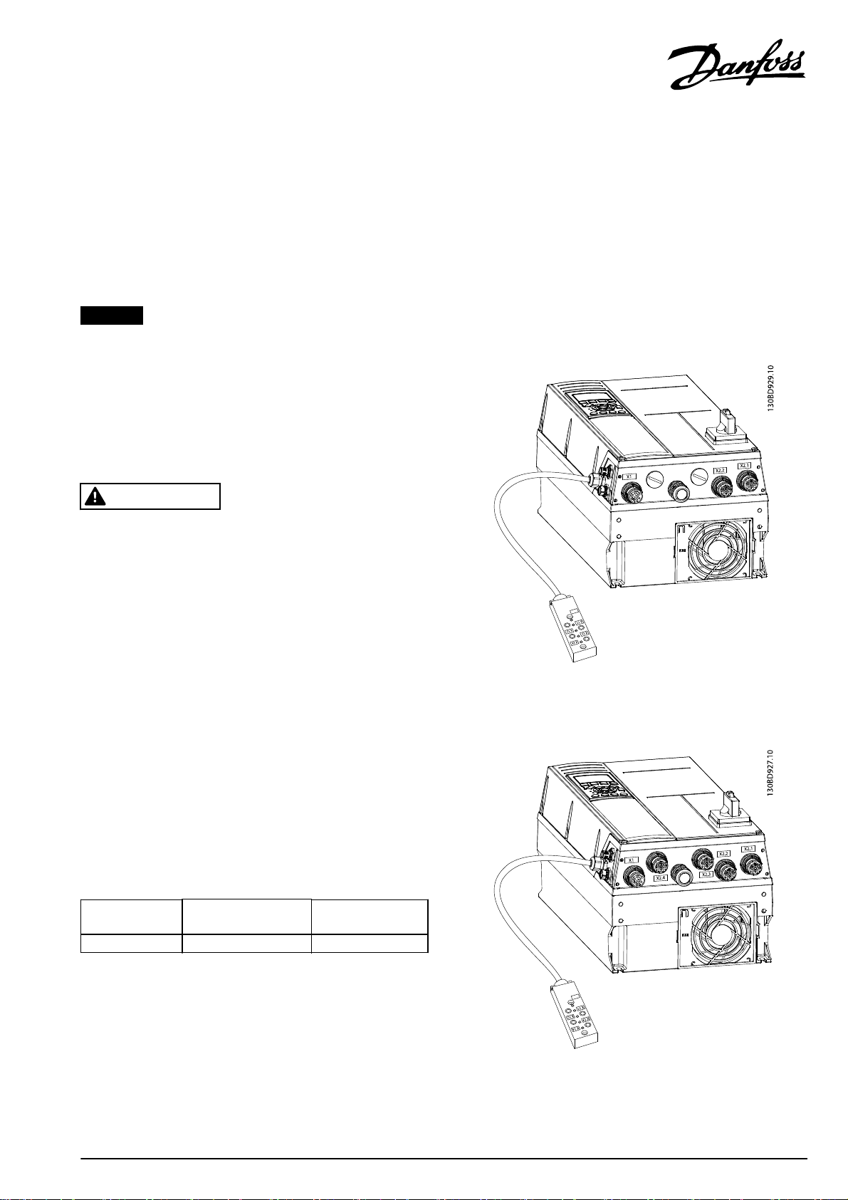
FC 302 with 2 motor connectors (134N3195)
Illustration 3.1 2 Motor Connectors
FC 302 with 4 motor connectors (134N3196)
Volt age
[V]
3x400 0.55–7.5 (0.75–10) 4
Tab le 2.1 Dis char ge Ti m e
Power range
[kW (hp)]
Minimum waiting
time (minutes)
Illustration 3.2 4 Motor Connectors
Danfoss A/S © 11/2015 All rights reserved. MI04G402

Installation Instructions VLT® AutomationDrive FC 302 with Connectors
FC 302 with MCO - mains connectors and 4 cable glands
(134N8410)
Illustration 3.3 Mains Connectors and 4 Cable Glands
FC 302 with connectors - side view
Illustration 3.4 Side View
Connectors
Overview
The frequency converter has 7 connectors plus 2 or 4 motor
connectors.
Label Connector Description
X1 Mains Mains in M23 (in M25) Male
X2.1-X2.4 Motor Motor connection M23 Female
X51 PROFIBUS - Male PROFIBUS M12
X52 PROFIBUS - Female PROFIBUS M12
X11-X14 I/O box connector Phoenix I/O box
Table 4.1 Connectors
X1- Mains M23 (in M25) Male
General ratings
Pins 1, 2, 3, and 4: 480 V AC, maximum 15 A.
•
Pins C and D: 30 V DC, maximum 3 A.
•
Tightening torque: 1.5–2.0 Nm (13.3–17.7 in-lb)
•
Pin Label Connected to frequency
converter wiring schematic
1 T1 91 (L1) 2.5 (14)
4 T2 92 (L2) 2.5 (14)
3 T3 93 (L3) 2.5 (14)
2 PE 95 (PE) 2.5 (14)
D 0 V DC 35 0.75 (18)
C 24 V DC 36 0.75 (18)
Minimum
wire [mm
(AWG)]
2
NOTICE
See the VLT® AutomationDrive FC 301/FC 302 Design Guide
for dimensions and further information.
Table 4.2 Wire/Connector Assignment for Plug X1
Mating part: Mains X1 (female)
Phoenix ordering number: KK-0885/XX,XX
2
Danfoss A/S © 11/2015 All rights reserved. MI04G402

Installation Instructions VLT® AutomationDrive FC 302 with Connectors
X2.1–X2.4 Motor Connectors M23 (in M25)
Female
General ratings
Pins 1, 2, 3, and 4: 480 V AC, maximum 15 A.
•
Pins C and D: 30 V DC, maximum 3 A.
•
Tightening torque: 1.5–2.0 Nm (13.3–17.7 in-lb).
•
Pin Label Connected to frequency
converter wiring schematic
1 U 96 (U) 2.5 (14)
3 V 97 ( V) 2.5 (14)
4 W 98 ( W) 2.5 (14)
2 PE 99 (PE) 2.5 (14)
Table 4.3 Wire/Connector Assignment for Plug X2
Minimum
wire [mm
(AWG)]
Mating part: Motor X2 (male)
Phoenix ordering number: KCX-K0341/XX,XX
Maximum cable length: 7.0 m (23 ft)
2 Motor Connection Variant (134N3195)
To meet the protection rating, always keep blind plugs
installed.
Label Connected to frequency converter wiring schematic
X2.1-B 53
X2.2-A 50
X2.1-A and
X2.2-B
X2.1-C and
X2.2-C
X2.1-D and
X2.2-D
Tab le 4.4 2 M oto r C onn e ctio n
Connected to a common terminal
Connected to an open terminal available in the
frequency converter
Connected to an open terminal available in the
frequency converter
4 Motor Connection Variant (134N3196)
Label Connected to frequency converter wiring schematic
X2.1-B 53
X2.4-A 50
X2.1-A and
X2.2-B
X2.2-A and
X2.3-B
X2.3-A and
X2.4-B
Tab le 4.5 4 M oto r C onn e ctio n
Connected via an internal terminal
Connected via an internal terminal
Connected via an internal terminal
X51 PROFIBUS M12 Male, X52 PROFIBUS M12
Female
General ratings
30 V DC, maximum 1 A.
•
Tightening torque: 0.2–0.3 Nm (1.8–2.7 in-lb)
•
Label Connected to frequency converter PROFIBUS
connector
2
15 V DC 67
2– 63
30 V DC 66
4– 62
Table 4.6 PROFIBUS Connection
Mating part: PROFIBUS X52 and X51 (female/male)
Phoenix ordering number: SAC-2P-MSB/ XX,XX-910/FSB SCO CT
X11–X14 I/O Connector Box (134N3195–
134N3196)
Phoenix sensor/actuator box - SACB-4/4-L-0,57HPUR CDA -
1531426.
Tightening torque sensor/actuator cable: 0.4 Nm (3.5 in-lb).
Label Wire Connected to frequency converter
wiring schematic
X11-X14 1
X11-X14 3 Blue 20 COM D IN
X14-4 Gray 33 D IN
X13-4 Yellow 29 D IN/OUT
X12-4 Green 19 D IN
X11-4 White 18 D IN
Table 4.7 Connector Box (134N3195–134N3196)
Brown 12
+24 V OutX11-X14 2
X11–X14 I/O Connector Box (134N8410)
Phoenix sensor/actuator box - SACB-4/4-L-0,57HPUR CDA -
1531426.
Tightening torque sensor/actuator cable: 0.4 Nm (3.5 in-lb)
Label Wire Connected to wiring schematic
X11-X14 1
X11-X14 2
X11-X14 3 Blue 20 COM D IN
X14-4 Gray
X13-4 Yellow X57-3 –
X12-4 Green X57-2 –
X11-4 White X57-1 –
Brown
Connected to
frequency
converter wiring
schematic
Connected to C-
option, MCO 305
wiring schematic
12
X57-4 –
+24 V Out
Table 4.8 Connector Box (134N8410)
MI04G402 Danfoss A/S © 11/2015 All rights reserved.
3

Overview of Marking and Cable Glands
(134N8410)
Allowed cable
Marking Type of cable gland
Encoder EMC M20x1,5 7.5–14.0 7.5–14.0 (0.3–0.55)
Motor EMC M25x1,5 10.0–18.0 10.0–18.0 (0.4–0.7)
Brake EMC M20x1,5 7.5–14.0 7.5–14.0 (0.3–0.55)
I/O M25x1.5 50.625 (plastic RAL 7035) 11–16 (0.45–0.6)
Table 4.9 Cable Glands (134N8410)
diameter [mm (in)]
Installation
NOTICE
For installation, refer to the VLT® AutomationDrive FC 301/FC
302 Operating Instructions.
NOTICE
For installation of 134N8410 FC 302 with MCO, also refer to
®
the VLT
Instructions.
Motion Control Option MCO 305 Operating
Danfoss can accept no responsibility for possible errors in catalogues, brochures and other printed material. Danfoss reserves the right to alter its products without notice. This also applies to products already on
order provided that such alterations can be made without subsequential changes being necessary in specifications already agreed. All trademarks in this material are property of the respective companies. Danfoss
and the Danfoss logotype are trademarks of Danfoss A/S. All rights reserved.
Danfoss A/S
Ulsnaes 1
DK-6300 Graasten
vlt-drives.danfoss.com
MI04G402130R0611 11/2015
*MI04G402*
 Loading...