

Page 1
Design Guide
VLT® AutomationDrive FC 301/302
0.25–75 kW
Page 2

Page 3

ContentsDesign Guide | VLT® AutomationDrive FC 301/302
Contents
1 Introduction 12
1.1 Purpose of this Design Guide 12
1.2 Trademarks 12
1.3 Additional Resources 12
1.4 Document Version 13
1.5 Conventions 13
2 Safety 14
2.1 Safety 14
2.2 Safety Symbols 14
2.3 Qualified Personnel 14
3 Approvals and Certifications 15
3.1 Regulatory/Compliance Approvals 15
3.2 Typical Product Approvals and Certifications for VLT® Drives 15
3.3 Export Control Regulation 18
3.4 Enclosure Protection Rating 18
4 VLT® Product Family Overview 19
4.1 VLT® Drives 19
4.2 Product Overview of the VLT® AutomationDrive FC 301/302 19
4.3 Power Drive Systems 23
4.3.1 Ecodesign for Power Drive Systems 23
4.3.1.1 Losses in Mains Cabling 25
4.3.1.2 Input Filters: Line Reactors and Harmonic Filters 25
4.3.1.3 Drive, Input Side 26
4.3.1.4 DC Link 27
4.3.1.5 Drive, Output Side 28
4.3.1.6 Motor Cables and Motor 29
5 Product Overview 30
5.1 Overview of Drives Systems 30
5.1.1 Filter Options 30
5.1.1.1 Protection of Motor Insulation 31
5.1.1.2 Reduction of Motor Acoustic Noise 31
5.1.1.3 Reduction of High-frequency Electromagnetic Noise in Motor Cables 31
5.1.1.4 Bearing Currents and Shaft Voltage 31
5.1.2 Supported Motor Types 32
5.1.3 Bearing Currents 33
5.2 Integrated Motion Controller 36
AJ286655760917en-000101 / | 3Danfoss A/S © 2019.10
Page 4

ContentsDesign Guide | VLT® AutomationDrive FC 301/302
5.2.1 Positioning, Homing, and Synchronization 36
5.2.1.1 Positioning 36
5.2.1.2 Homing 37
5.2.1.3 Synchronization 37
5.2.1.4 Fieldbus References 38
5.2.2 Control 39
5.2.2.1 Control Loops 39
5.2.2.2 Control and Status Signals 40
5.3 Functional Safety 42
5.3.1 Protection of Personnel and Equipment 42
5.3.2 VLT® Safety Option MCB 150 and MCB 151 42
5.3.3 VLT® Sensorless Safety MCB 159 43
5.3.4 VLT® Safety Option MCB 152 43
5.3.5 Safety Functions 43
5.4 Danfoss VLT® FlexConcept® 45
5.5 Torque Sharing/Droop 46
5.6 Power Limit Function 47
5.7 Service Log 49
5.8 Maintenance Functions 49
6 Product Features 52
6.1 Automated Operational Features 52
6.1.1 Short-circuit Protection 52
6.1.2 Overvoltage Protection 52
6.1.3 Missing Motor Phase Detection 53
6.1.4 Mains Phase Imbalance Detection 53
6.1.5 Switching on the Output 53
6.1.6 Overload Protection 54
6.1.7 Locked Rotor Protection 54
6.1.8 Automatic Derating 54
6.1.8.1 Overview of Automatic Derating 55
6.1.8.2 Sine-wave Filter Fixed Mode 56
6.1.8.3 Overview Table 57
6.1.8.4 High Motor Load 58
6.1.8.5 High Voltage on the DC link 58
6.1.8.6 Low Motor Speed 58
6.1.8.7 High Internal Temperature 59
6.1.8.8 Current 60
6.1.9 Automatic Energy Optimization 60
6.1.10 Automatic Switching Frequency Modulation 61
6.1.11 Automatic Derating for High Switching Frequency 61
6.1.12 Power Fluctuation Performance 61
AJ286655760917en-000101 /4 | Danfoss A/S © 2019.10
Page 5

ContentsDesign Guide | VLT® AutomationDrive FC 301/302
6.1.13 Resonance Damping 61
6.1.14 Temperature-controlled Fans 61
6.1.15 EMC Compliance 61
6.1.16 Galvanic Isolation of Control Terminals 62
6.2 Custom Application Features 62
6.2.1 Automatic Motor Adaptation (AMA) 62
6.2.2 Motor Thermal Protection 62
6.2.3 Motor Thermal Protection for Ex-e or Ex-n Motors 63
6.2.4 Mains Dropout 65
6.2.5 Built-in PID Controller 65
6.2.6 Automatic Restart 65
6.2.7 Flying Start 65
6.2.8 Full Torque at Reduced Speed 65
6.2.9 Frequency Bypass 66
6.2.10 Motor Preheat 66
6.2.11 Programmable Set-ups 66
6.2.12 Smart Logic Controller 66
6.2.13 Safe Torque Off 68
6.3 Dynamic Braking Overview 68
6.4 Mechanical Holding Brake Overview 69
6.4.1 Open-loop Mechanical Brake Control 69
6.4.2 Closed-loop Mechanical Brake Control/Hoist Mechanical Brake 70
6.5 Load Sharing Overview 71
6.5.1 Preconditions and Special Conditions 72
6.5.2 Combinations of Enclosure Sizes 73
6.6 Regen Overview 74
7 Options and Accessories Overview 76
7.1 Introduction 76
7.2 VLT® FC Series Options Concept 76
7.3 VLT® Fieldbus Options 77
7.4 VLT® Functional Extensions 78
7.5 VLT® Programmable Controllers 78
7.6 VLT® Power Options 79
7.6.1 VLT® Harmonic Filters 79
7.6.2 VLT® Sine-wave Filters 79
7.6.3 VLT® dU/dt Filters 80
7.6.4 VLT® Common-mode Filters 80
7.6.5 VLT® Brake Resistors 80
7.6.6 VLT® Line Reactors 81
7.7 Kits and Accessories 81
7.7.1 Panel Through Mounting Kits for VLT® FC Series Enclosure Sizes A, B, and C 81
AJ286655760917en-000101 / | 5Danfoss A/S © 2019.10
Page 6

ContentsDesign Guide | VLT® AutomationDrive FC 301/302
7.7.2 IP21/NEMA Type 1 Enclosure Kits for VLT® FC Series Enclosure Sizes A, B, and C 82
7.7.3 Mounting Brackets for VLT® FC Series Enclosure Sizes A5, B1, B2, C1, and C2 86
7.7.4 Remote Mounting Kits for LCP 88
7.7.4.1 Remote Mounting Kit for LCP 102 and LCP 103 with Cover for Outdoor Mounting 88
7.7.4.2 Panel Mounting Kit for LCP 102, LCP 101, and LCP 103 89
7.7.5 VLT® Wireless Communication Panel LCP 103 and MyDrive® Connect 91
8 Specifications 92
8.1 Enclosure Size by Power Rating 92
8.2 Electrical Data 94
8.2.1 Mains Supply 3x200–240 V AC, T2 94
8.2.2 Mains Supply 3x380–480 V AC, FC 301 T4 and 3x380–500 V AC, FC 302 T5 97
8.2.3 Mains Supply 3x525–600 V AC, T6 101
8.2.4 Mains Supply 3x525–690 V AC, T7 105
8.2.5 Power Cable Cross-sections 108
8.3 Mains Supply 109
8.4 Motor Output and Motor Data 109
8.4.1 Motor Output (U, V, W) 109
8.4.2 Torque Characteristics 110
8.5 Ambient Conditions 110
8.6 Cable Specifications 111
8.6.1 Cable Lengths and Cross-sections for Control Cables 111
8.7 Control Input/Output and Control Data 111
8.7.1 Digital Inputs 111
8.7.2 STO Terminal 37 111
8.7.3 Analog Inputs 112
8.7.4 Pulse/Encoder Inputs 112
8.7.5 Digital Outputs 113
8.7.6 Analog Output 113
8.7.7 Control Card, 24 V DC Output 114
8.7.8 Control Card, +10 V DC Output 114
8.7.9 Control Card, RS485 Serial Communication 114
8.7.10 Control Card, USB Serial Communication 114
8.7.11 Relay Outputs 114
8.7.12 Control Card Performance 115
8.7.13 Control Characteristics 115
8.8 Connection Tightening Torques 116
8.9 Power Ratings, Weight, and Dimensions 117
9 Mechanical Installation Considerations 122
9.1 Storage 122
9.2 Operating Environment 122
AJ286655760917en-000101 /6 | Danfoss A/S © 2019.10
Page 7

ContentsDesign Guide | VLT® AutomationDrive FC 301/302
9.2.1 Gases 122
9.2.2 Dust 123
9.2.3 Outdoor Installation in freezing Temperature Environments 124
9.2.4 Potentially Explosive Atmospheres 125
9.2.5 Vibration and Shock 126
9.2.6 Maintenance 126
9.3 Mounting Configurations 126
9.3.1 Side-by-side Mounting 126
9.3.2 Wall Mounting 128
9.4 Derating 129
9.4.1 Derating for Running at Low Speed 129
9.4.2 Derating for Low Air Pressure 130
9.4.3 Derating for Ambient Temperature and Switching Frequency 131
9.4.3.1 Derating for Ambient Temperature, Enclosure Size A 131
9.4.3.2 Derating for Ambient Temperature, Enclosure Size B 132
9.4.3.3 Derating for Ambient Temperature, Enclosure Size C 137
10 Electrical Installation Considerations 141
10.1 Safety Instructions 141
10.2 Wiring Schematic 143
10.3 Connections 144
10.3.1 Power Connections 144
10.3.2 IT Grid Connection 145
10.3.3 DC Bus Connection 146
10.3.4 Load Sharing Connection 146
10.3.5 Brake Cable Connection 147
10.3.6 Grounding 147
10.3.7 Safety Ground Connection 147
10.4 Cables 147
10.4.1 EMC-correct Cables 147
10.4.2 Preparing Cable Entry Holes 149
10.4.3 Specifications of Entry Holes 149
10.4.3.1 Entry Holes, Enclosure Size A2, IP21 149
10.4.3.2 Entry Holes, Enclosure Size A3, IP21 150
10.4.3.3 Entry Holes, Enclosure Size A4, IP55 150
10.4.3.4 Entry Holes, Enclosure Size A4, IP55 Threaded Gland Holes 151
10.4.3.5 Entry Holes, Enclosure Size A5, IP55 151
10.4.3.6 Entry Holes, Enclosure Size A5, IP55 Threaded Gland Holes 152
10.4.3.7 Entry Holes, Enclosure Size B1, IP21 152
10.4.3.8 Entry Holes, Enclosure Size B1, IP55 153
10.4.3.9 Entry Holes, Enclosure Size B1, IP55 Threaded Gland Holes 153
10.4.3.10 Entry Holes, Enclosure Size B2, IP21 154
AJ286655760917en-000101 / | 7Danfoss A/S © 2019.10
Page 8

ContentsDesign Guide | VLT® AutomationDrive FC 301/302
10.4.3.11 Entry Holes, Enclosure Size B2, IP55 155
10.4.3.12 Entry Holes, Enclosure Size B2, IP55 Threaded Gland Holes 155
10.4.3.13 Entry Holes, Enclosure Size B3, IP21 156
10.4.3.14 Entry Holes, Enclosure Size C1, IP21 156
10.4.3.15 Entry Holes, Enclosure Size C2, IP21 157
10.4.4 Tightening Torques for Cover 157
10.5 Control Wiring and Terminals 158
10.5.1 Shielded Control Cables 158
10.5.2 Wiring to Control Terminals 159
10.5.3 Control Terminal Types 160
10.5.4 Terminal Descriptions 161
10.6 Fuses and Circuit Breakers 162
10.6.1 Fuse Recommendations 162
10.6.2 CE Compliance 163
10.6.3 UL Compliance 166
10.7 Relays 168
10.7.1 Overview of Relay Terminals 170
10.8 Disconnects and Contactors 171
10.9 Motor 173
10.9.1 Motor Thermal Protection 174
10.9.2 Parallel Connection of Motors 174
10.9.3 Motor Insulation 175
10.9.4 Motor Bearing Currents 176
10.10 Braking 176
10.10.1 Selection of Brake Resistor 176
10.10.2 Control with Brake Function 179
10.11 Residual Current Device 180
10.12 Leakage Current 180
10.12.1 Using a Residual Current Device (RCD) 182
10.13 Efficiency 183
10.14 Acoustic Noise and Airflow 184
10.15 dU/dt Conditions 185
10.15.1 dU/dt Values, 200–240 V (T2) 186
10.15.1.1 dU/dt Values for P5K5T2, 200–240 V 186
10.15.1.2 dU/dt Values for P7K5T2, 200–240 V 186
10.15.1.3 dU/dt Values for P11KT2, 200–240 V 186
10.15.1.4 dU/dt Values for P15KT2, 200–240 V 187
10.15.1.5 dU/dt Values for P18KT2, 200–240 V 187
10.15.1.6 dU/dt Values for P22KT2, 200–240 V 187
10.15.1.7 dU/dt Values for P30KT2, 200–240 V 187
10.15.1.8 dU/dt Values for P37KT2, 200–240 V 187
10.15.2 dU/dt Values, 380–480 V (T4) 188
AJ286655760917en-000101 /8 | Danfoss A/S © 2019.10
Page 9

ContentsDesign Guide | VLT® AutomationDrive FC 301/302
10.15.2.1 dU/dt Values for P1K5T4, 380–480 V 188
10.15.2.2 dU/dt Values for P4K0T4, 380–480 V 188
10.15.2.3 dU/dt Values for P7K5T4, 380–480 V 188
10.15.2.4 dU/dt Values for P11KT4, 380–480 V 188
10.15.2.5 dU/dt Values for P15KT4, 380–400 V 189
10.15.2.6 dU/dt Values for P18KT4, 380–480 V 189
10.15.2.7 dU/dt Values for P22KT4, 380–480 V 189
10.15.2.8 dU/dt Values for P30KT4, 380–480 V 189
10.15.2.9 dU/dt Value for P37KT4, 380–480 V 190
10.15.2.10dU/dt Values for P45KT4, 380–480 V 190
10.15.3 dU/dt Values, 380–500 V (T5) 190
10.15.3.1 dU/dt Values for P55KT5, 380–500 V 190
10.15.3.2 dU/dt Values for P75KT5, 380–500 V 190
10.15.4 dU/dt Values, 600 V (T6) 190
10.15.4.1 dU/dt Values for P15KT6, 600 V 191
10.15.4.2 dU/dt Values for P30KT6, 600 V 191
10.15.4.3 dU/dt Values for P75KT6, 600 V 191
10.15.5 dU/dt Values, 525–690 V (T7) 191
10.15.5.1 dU/dt Values for P7K5T7, 525–690 V 191
10.15.5.2 dU/dt Values for P45KT7, 525–690 V 192
10.16 Electromagnetic Compatibility (EMC) Overview 192
10.16.1 EMC Test Results 192
10.16.2 Emission Requirements 193
10.16.3 Immunity Requirements 194
10.16.4 EMC Compatibility 196
10.17 EMC-compliant Installation 197
10.18 Harmonics Overview 200
10.18.1 Harmonics Analysis 200
10.18.2 Effect of Harmonics in a Power Distribution System 201
10.18.3 IEC Harmonic Standards 202
10.18.4 Harmonic Results (Emission) 203
10.18.5 Harmonic Mitigation 204
10.18.6 Harmonic Calculation 205
10.18.7 Line Reactors 205
11 Basic Operating Principles 206
11.1 Introduction 206
11.2 Drive Controls 206
11.2.1 Control Principle 206
11.2.2 Local (Hand On) and Remote (Auto On) Control 207
11.3 Reference Limits 209
11.4 PID Control 211
AJ286655760917en-000101 / | 9Danfoss A/S © 2019.10
Page 10

ContentsDesign Guide | VLT® AutomationDrive FC 301/302
11.4.1 Speed PID Control 211
11.4.2 Tuning PID Speed Control 212
11.4.3 Process PID Control 212
11.4.4 Advanced PID Control 213
11.5 More Operating Principles 213
11.5.1 FC 301 versus FC 302 Control Principle 214
11.5.2 Control Structure in VVC+ 215
11.5.3 Control Structure in Flux Sensorless 216
11.5.4 Control Structure in Flux with Motor Feedback 217
12 How to Order a Drive 218
12.1 Drive Configurator 218
12.1.1 Type Code 218
12.1.2 Language Packages 221
12.2 Order Numbers for Options and Accessories 222
12.2.1 Order Numbers for Options for Slot A 222
12.2.2 Order Numbers for Options for Slot B 222
12.2.3 Order Numbers for Options for Slot C 223
12.2.4 Order Numbers for Options for Slot D 223
12.2.6 Order Numbers for Miscellaneous Hardware 224
12.2.7 Order Numbers for Local Control Panel Options 225
12.2.8 Order Numbers for PC Software 226
12.2.9 Ordering of VLT® Brake Resistors MCE 101 226
12.2.9.1 Order Numbers for Brake Resistors FC 301, T2, Horizontal Braking 10% Duty Cycle 227
12.2.9.2 Order Numbers for Brake Resistors FC 301, T2, Vertical Braking 40% Duty Cycle 228
12.2.9.3 Order Numbers for Brake Resistors FC 301, T2, Flat-pack for Horizontal Conveyors 229
12.2.9.4 Order Numbers for Brake Resistors FC 301, T4, Horizontal Braking 10% Duty Cycle 229
12.2.9.5 Order Numbers for Brake Resistors FC 301, T4, Vertical Braking 40% Duty Cycle 231
12.2.9.6 Order Numbers for Brake Resistors FC 301, T4, Flat-pack for Horizontal Conveyors 232
12.2.9.7 Order Numbers for Brake Resistors FC 302, T2, Horizontal Braking 10% Duty Cycle 232
12.2.9.8 Order Numbers for Brake Resistors FC 302, T2, Vertical Braking 40% Duty Cycle 233
12.2.9.9 Order Numbers for Brake Resistors FC 302, T2, Flat-pack for Horizontal Conveyors 234
12.2.9.10 Order Numbers for Brake Resistors FC 302, T5, Horizontal Braking 10% Duty Cycle 235
12.2.9.11 Order Numbers for Brake Resistors FC 302, T5, Vertical Braking 40% Duty Cycle 236
12.2.9.12 Order Numbers for Brake Resistors FC 302, T5, Flat-pack for Horizontal Conveyors 237
12.2.9.13 Order Numbers for Brake Resistors FC 302, T6, Horizontal Braking 10% Duty Cycle 237
12.2.9.14 Order Numbers for Brake Resistors FC 302, T6, Vertical Braking 40% Duty Cycle 239
12.2.9.15 Order Numbers for Brake Resistors FC 302, T7, Vertical Braking 40% Duty Cycle 240
12.2.10 Order Numbers for Accessory Bags 241
12.2.11 Ordering of Harmonic Filters 241
12.2.11.1 Order Numbers for Harmonic Filters, 380–415 V, 50 Hz 242
12.2.11.2 Order Numbers for Harmonic Filters, 380–415 V, 60 Hz 243
AJ286655760917en-000101 /10 | Danfoss A/S © 2019.10
Page 11

ContentsDesign Guide | VLT® AutomationDrive FC 301/302
12.2.11.3 Order Numbers for Harmonic Filters, 440–480 V, 60 Hz 245
12.2.11.4 Order Numbers for Harmonic Filters, 600 V, 60 Hz 246
12.2.11.5 Order Numbers for Harmonic Filters, 500–690 V, 50 Hz 248
12.2.12 Order Numbers for VLT® Sine-wave Filters MCC 101 249
12.2.13 Order Numbers for VLT® dU/dt Filters MCC 102 250
12.2.15 Spare Parts 252
13 Appendix 253
13.1 Symbols and Abbreviations 253
AJ286655760917en-000101 / | 11Danfoss A/S © 2019.10
Page 12

Design Guide | VLT® AutomationDrive FC 301/302
Introduction
1 Introduction
1.1 Purpose of this Design Guide
This Design Guide is intended for qualified personnel, such as:
• Project and systems engineers.
• Design consultants.
• Application and product specialists.
The Design Guide provides technical information to understand the capabilities of the VLT® AutomationDrive FC 301/FC 302 for
integration into motor control and monitoring systems. Its purpose is to provide design considerations and planning data for
integration of the drive into a system. It caters for selection of drives and options for a diversity of applications and installations.
Reviewing the detailed product information in the design stage enables developing a well-conceived system with optimal
functionality and efficiency.
This manual is targeted at a worldwide audience. Therefore, wherever occurring, both SI and imperial units are shown.
1.2 Trademarks
VLT® is a registered trademark for Danfoss A/S.
1.3 Additional Resources
Various resources are available to understand advanced drive operation, programming, and directives compliance.
• The VLT® AutomationDrive FC 301/302 Operating Guide provides detailed information for the installation and start-up of the
drive.
• The VLT® AutomationDrive FC 301/302 Programming Guide provides greater detail on how to work with parameters. It also
contains application examples.
• The VLT® Condition-based Monitoring Programming Guide provides information on working with condition-based monitoring
parameters on the VLT® FC series AC drives.
• The VLT® Integrated Motion Control Application Guide provides information on working with the Integrated Motion Controller
(IMC) feature. The guide shows application examples, and presents the functionalities while showing required parameter settings
and connections.
• The VLT® Safe Torque Off Operating Guide describes how to use Danfoss VLT® drives in functional safety applications. This
manual is supplied with the drive when the Safe Torque Off option is present.
• The VLT® Brake Resistor MCE 101 Design Guide describes how to select the optimal brake resistor.
• The VLT® Advanced Harmonic Filters AHF 005/AHF 010 Design Guide describes harmonics, various mitigation methods, and
the operation principle of the advanced harmonic filter. This guide also describes how to select the correct advanced harmonics
filter for a particular application.
• The Output Filter Design Guide explains why it is necessary to use output filters for certain applications and how to select the
optimal dU/dt or sine-wave filter.
• Supplemental publications, drawings, EPLAN macros, and manuals are available at
Optional equipment is available that may change some of the information described in these publications. Be sure to follow the
instructions supplied with the options for specific requirements.
www.danfoss.com.
Contact a Danfoss supplier or visit www.danfoss.com for more information.
12 | Danfoss A/S © 2019.10
AJ286655760917en-000101 / 130R0301
Page 13

Design Guide | VLT® AutomationDrive FC 301/302
1.4 Document Version
This manual is regularly reviewed and updated. All suggestions for improvement are welcome.
The original language of this manual is English.
Table 1: Document Version
Edition Remarks
MG33BGxx New document structure. All chapters updated.
1.5 Conventions
• Numbered lists indicate procedures.
• Bulleted and dashed lists indicate listings of other information where the order of the information is not relevant.
• Bolded text indicates highlighting and section headings.
• Italicized text indicates the following:
- Cross-reference.
- Link.
- Footnote.
- Parameter name.
- Parameter option.
- Parameter group name.
- Alarms/warnings.
• All dimensions in drawings are in metric values (imperial values in brackets).
• An asterisk (*) indicates the default setting of a parameter.
Introduction
Danfoss A/S © 2019.10
AJ286655760917en-000101 / 130R0301| 13
Page 14
Design Guide | VLT® AutomationDrive FC 301/302
Safety
2 Safety
2.1 Safety
When designing AC drives, some residual dangers cannot be avoided constructively. One example is the discharge time, which is very
important to observe to avoid potential death or serious injury. For the Danfoss VLT® drives, the discharge time is from 4–40 minutes
depending on the drive size.
For further information on safety precautions, refer to the product-specific Operating Guide.
2.2 Safety Symbols
The following symbols are used in this manual:
DANGER
Indicates a hazardous situation which, if not avoided, will result in death or serious injury.
WARNING
Indicates a hazardous situation which, if not avoided, could result in death or serious injury.
CAUTION
Indicates a hazardous situation which, if not avoided, could result in minor or moderate injury.
NOTICE
Indicates information considered important, but not hazard-related (for example, messages relating to property damage).
2.3 Qualified Personnel
To allow trouble-free and safe operation of the unit, only qualified personnel with proven skills are allowed to transport, store,
assemble, install, program, commission, maintain, and decommission this equipment.
Persons with proven skills:
• Are qualified electrical engineers, or persons who have received training from qualified electrical engineers and are suitably
experienced to operate devices, systems, plant, and machinery in accordance with pertinent laws and regulations.
• Are familiar with the basic regulations concerning health and safety/accident prevention.
• Have read and understood the safety guidelines given in all manuals provided with the unit, especially the instructions given in the
Operating Guide.
• Have good knowledge of the generic and specialist standards applicable to the specific application.
14 | Danfoss A/S © 2019.10
AJ286655760917en-000101 / 130R0301
Page 15
Design Guide | VLT® AutomationDrive FC 301/302
Approvals and Certifications
3 Approvals and Certifications
3.1 Regulatory/Compliance Approvals
This section provides a brief description of the various approvals and certifications that are on Danfoss VLT® drives. Not all approvals
are on all drives.
NOTICE
IMPOSED LIMITATIONS ON THE OUTPUT FREQUENCY
From software version 6.72 onwards, the output frequency of the drive is limited to 590 Hz due to export control regulations.
Software versions 6.xx also limit the maximum output frequency to 590 Hz, but these versions cannot be flashed, that is,
neither downgraded nor upgraded.
3.2 Typical Product Approvals and Certifications for VLT® Drives
The VLT® AutomationDrive product series complies with a wide scope of required standards and directives. Information on the specific
product certifications can be found on the product nameplate.
3.2.1 CE Mark
The drive complies with relevant directives and their related standards for the extended Single Market in the European Economic Area.
Table 2: EU directives applicable to drives
EU Directive Version
Low Voltage Directive 2014/35/EU
EMC Directive 2014/30/EU
Machinery Directive
(1)
ErP Directive 2009/125/EU
ATEX Directive 2014/34/EU
RoHS Directive
Radio Equipment Directive
(2)
(3)
REACH Directive 1907/2006/EC
1
Machinery Directive conformance is only required for drives with an integrated safety function.
2
For China RoHS, contact Danfoss application support to get the certificate.
3
Radio Equipment Directive is only required for interfaces supporting wireless communication.
2014/42/EU
2011/65/EU
2014/53/EU
Danfoss A/S © 2019.10
AJ286655760917en-000101 / 130R0301| 15
Page 16

Design Guide | VLT® AutomationDrive FC 301/302
Approvals and Certifications
3.2.2 Low Voltage Directive
The aim of the Low Voltage Directive is to protect persons, domestic animals and property against dangers caused by the electrical
equipment, when operating electrical equipment that is installed and maintained correctly, in its intended application. The directive
applies to all electrical equipment in the 50–1000 V AC and the 75–1500 V DC voltage ranges.
3.2.3 EMC Directive
The purpose of the EMC (electromagnetic compatibility) Directive is to reduce electromagnetic interference and enhance immunity of
electrical equipment and installations. The basic protection requirement of the EMC Directive states that devices that generate
electromagnetic interference (EMI), or whose operation could be affected by EMI, must be designed to limit the generation of
electromagnetic interference and shall have a suitable degree of immunity to EMI when properly installed, maintained, and used as
intended. Electrical equipment devices used alone or as part of a system must bear the CE mark. Systems do not require the CE mark,
but must comply with the basic protection requirements of the EMC Directive.
3.2.4 Machinery Directive
The aim of the Machinery Directive is to ensure personal safety and avoid property damage to mechanical equipment used in its
intended application. The Machinery Directive applies to a machine consisting of an aggregate of interconnected components or
devices of which at least 1 is capable of mechanical movement. Drives with an integrated functional safety function must comply with
the Machinery Directive. Drives without a functional safety function do not fall under the Machinery Directive. If a drive is integrated
into a machinery system, Danfoss can provide information on safety aspects relating to the drive. When drives are used in machines
with at least 1 moving part, the machine manufacturer must provide a declaration stating compliance with all relevant statutes and
safety measures.
3.2.5 ErP Directive
The ErP directive is the European Ecodesign Directive for energy-related products. The directive sets ecodesign requirements for
energy-related products, including drives, and aims at reducing the energy consumption and environmental impact of products by
establishing minimum energy-efficiency standards.
3.2.6 ATEX Directive
Illustration 1: ATEX Logo
3.2.7 Radio Equipment Directive
Devices that emit or receive radio waves as part of radio communication are required to comply with the Radio Equipment Directive.
The drive itself does not contain a radio device, and hence compliance to the directive is not relevant. However, user interfaces
containing active radio devices, such as the integrated control panel with wireless communication capabilities, comply with the
directive.
16 | Danfoss A/S © 2019.10
AJ286655760917en-000101 / 130R0301
Page 17
089
Design Guide | VLT® AutomationDrive FC 301/302
Approvals and Certifications
3.2.8 UL Listing
3.2.9 CSA/cUL
3.2.10 TÜV
TÜV is a European safety organization which certifies the functional safety of the drive in accordance to EN/IEC 61800-5-2. The TÜV
both tests products and monitors their production to ensure that companies stay compliant with their regulations.
3.2.11 EAC
Illustration 2: EAC Mark
The EAC logo must be both on the product label and on the packaging label. All products used within the EAC area, must be bought at
Danfoss inside the EAC area.
3.2.12 UkrSEPRO
Illustration 3: UkrSEPRO Mark
3.2.13 RCM Mark Compliance
Illustration 4: RCM Mark
3.2.14 Marine Type Approvals
VLT® AutomationDrive drives have several marine type approvals. For a list of the approvals and certifications, see the FC 301/FC 302
product page at www.danfoss.com.
Danfoss A/S © 2019.10
AJ286655760917en-000101 / 130R0301| 17
Page 18

Design Guide | VLT® AutomationDrive FC 301/302
Approvals and Certifications
3.2.15 Moroccan Conformity Mark
Illustration 5: Morocco CMIM Mark
The drive complies with relevant directives and their related standards for the Morocco market.
3.3 Export Control Regulation
AC drives can be subject to regional and/or national export control regulations. Both the EU and USA have regulations for so-called
dual-use products (products for both military and non-military use), which currently includes AC drives with a capacity to operate 600–
2000 Hz. These products can still be sold, but it requires a set of measures, for example a license, or an end-user statement.
An ECCN number is used to classify all AC drives that are subject to export control regulations. The ECCN number is provided in the
documentation accompanying the AC drive. If the AC drive is re-exported, it is the responsibility of the exporter to ensure compliance
with the relevant export control regulations.
For further information, contact Danfoss Drives Global or the local sales office.
3.4 Enclosure Protection Rating
The VLT® drive series are available in various enclosure protection ratings to accommodate the needs of the application. Enclosure
protection ratings are provided based on 2 international standards:
• UL type validates that the enclosures meet NEMA (National Electrical Manufacturers Association) standards. The construction and
testing requirements for enclosures are provided in NEMA Standards Publication 250-2003 and UL 50, 11th edition.
• IP (Ingress Protection) ratings outlined by the IEC (International Electrotechnical Commission) in the rest of the world. The standard
Danfoss VLT® drive series are available in various enclosure protections to meet the requirements of IP00 (Chassis), IP20 (Protected
chassis), IP21 (NEMA Type 1), or IP54 (NEMA Type 12). In this manual, NEMA Type is written as Type, for example, IP21/Type 1.
18 | Danfoss A/S © 2019.10
AJ286655760917en-000101 / 130R0301
Page 19

Design Guide | VLT® AutomationDrive FC 301/302
VLT® Product Family Overview
4 VLT® Product Family Overview
4.1 VLT® Drives
Danfoss offers 3 types of AC drives in different-sized enclosures for a wide range of applications, with power ratings from 0.25–1200 kW
(0.34–1350 hp).
Standalone drives (frequency converters)
The Danfoss standalone drives are so robust that they can be mounted outside of cabinets virtually anywhere, even right beside the
motor. Equipped for the toughest of environment, they suit any application.
More uncompromising features:
• Enclosure sizes with protection ratings up to IP54/UL Type 12.
• Full EMC compliance according to international standards.
• Ruggedized and coated PCBs.
• Wide temperature range, operating from -25 to +40 °C (-13 to 104 °F) without derating.
• Motor cable lengths up to 150 m (492 ft) for shielded cables and 300 m (984 ft) for unshielded cables.
Enclosed drives
Danfoss enclosed drives are designed with the installer and operator in mind to save time on installation, commissioning, and
maintenance. The enclosed drives are designed for full access from the front. After opening the cabinet door, all components can be
reached without removing the drive, even when mounted side by side. Several cooling options, including back-channel cooling,
provide optimum adaption to the installation location and application.
More time-saving features:
• An intuitive user interface with an award-winning local control panel (LCP) and common control platform that streamlines start-up
and operating procedures.
• Robust design and advanced controls make Danfoss drives virtually maintenance free.
System modules
The compact design of the system modules makes them easy to fit even in small spaces. Integrated filters, input fuses, options, and
accessories provide extra capabilities and protection without increasing the enclosure size.
More space-saving features:
• Built-in DC-link reactors for harmonic suppression eliminate the need for higher loss external AC line reactors.
• Optional built-in RFI filters are available throughout the power range.
• Regen terminals are available within the standard enclosures (for enclosure sizes D, E, and F).
• In addition to the many valuable features that the Danfoss drives offers as standard, there are several other control, monitoring,
and power options available in pre-engineered factory configurations.
For more details on the enclosure types, the modularity, and the applications, see the product-specific Selection Guides on
www.danfoss.com.
4.2 Product Overview of the VLT® AutomationDrive FC 301/302
The VLT® AutomationDrive FC 301/FC 302 is a drive for controlling
Danfoss A/S © 2019.10
AJ286655760917en-000101 / 130R0301| 19
Page 20

Design Guide | VLT® AutomationDrive FC 301/302
• Asynchronous AC induction motors,
• Permanent magnet synchronous motors,
• AC induction servomotors, and
• Synchronous reluctance motors (SynRM motors).
As other Danfoss AC drives, the VLT® AutomationDrive is motor independent, meaning that the drive can be connected to any brand of
motor, thus providing great flexibility when designing an installation.
The FC 301/FC 302 is built on a modular concept design and is equipped with a wide range of features enabling optimal process
control and high-quality output. With the many features, the drive meets the requirements of many industrial, chemical, and marine
applications, for example:
• Operating pumps.
• Conveyors.
• Material handling equipment.
• Hoists.
• Steering gear.
• Extruders.
• Palletizers.
In typical installations, the drive forms part of a bigger system and can be supplied with extra equipment, for example brakes, kits, and
various filters.
VLT® Product Family Overview
Adding to the flexibility are the different ways of connectivity, and as the drive supports all leading industry fieldbusses, it is
independent of the fieldbus system being used. The drive can be controlled:
• Directly from the local LCP.
• Local digital I/O or via industrial network connection.
• Wireless via the VLT® Wireless Control Panel LCP 103. The LCP 103 connects to the MyDrive® Connect app and enables control from
a mobile device.
Easy installation and commissioning
The FC 301/FC 302 comes with pluggable and spring-loaded I/O terminals making wiring and installation easy. During commissioning,
the FC 301/FC 302 offers time-saving application-dependent functions, such as:
• Droop for load sharing.
• Integrated brake control for safe operation of hoists.
• Integrated process controller for demand-based pumping.
• Power limit function for limiting the motor power distributed to the motor when required.
Commissioning can be made effectively via the VLT® Motion Control Tool MCT 10, which is a PC tool designed especially for drive
commissioning. The tool contains many features, and it is also possible to create Smart Assisted Start-up wizards, define initial
parameter values, and much more.
To ensure optimal control of the motor, the VLT® AutomationDrive offers a built-in algorithm, automatic motor adaptation (AMA). At
commissioning, program the function via the parameters to fine-tune the drive to match the motor.
Power sizes, voltage ranges, and enclosure protection classes
The VLT® AutomationDrive FC 301/FC 302 is available in many power sizes, voltage ranges, and enclosure protection classes, which
makes it easy to find the perfect drive for a given application.
20 | Danfoss A/S © 2019.10
AJ286655760917en-000101 / 130R0301
Page 21
e30ba870.11
e30ba809.11
e30ba810.11
e30bb458.11
e30ba811.11
Design Guide | VLT® AutomationDrive FC 301/302
Table 3: Voltage Ranges and Power Ranges
VLT® Product Family Overview
Voltage ranges [V] Power ranges [kW (hp)]
3 x 200–240 0.25–37 (0.34–50)
3 x 380–480/500 0.37–800 (0.5–1075)
3 x 525–600 0.75–75 (1.0–100)
3 x 525–690 1.1–1200 (1.5–1600)
Enclosure protection ratings:
• IP20/Chassis
• IP21/Type 1
• IP54/Type 12
• IP55/Type 12
• IP66/Type 4X
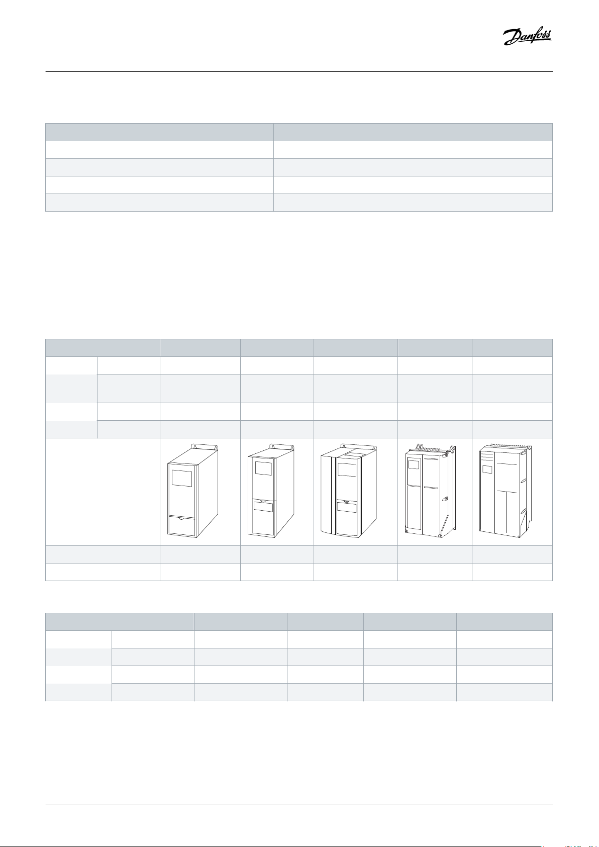
Table 4: Enclosures A1–A5: Power Sizes, Voltage Ranges, and Protection Rating
Enclosure A1 A2 A3 A4 A5
Power
[kW]
200–240 V 0.25–1.5 0.25–2.2 3–3.7 0.25–2.2 0.25–3.7
380–480/500V0.37–1.5 0.37–4 5.5–7.5 0.37–4 0.37–7.5
525–600 V – – 0.75–7.5 – 0.75–7.5
525–690 V – – 1.1–7.5 – –
IP 20 20/21 20/21 55/66 55/66
NEMA Chassis Chassis/Type 1 Chassis/Type 1 Type 12/4X Type 12/4X
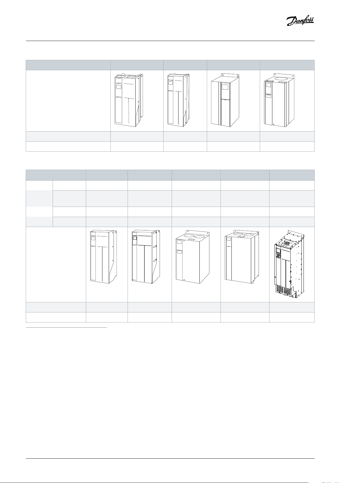
Table 5: Enclosures B1–B4: Power Sizes, Voltage Ranges, and Protection Rating
Enclosure B1 B2 B3 B4
Power [kW] 200–240 V 5.5–7.5 11 5.5–7.5 11–15
Danfoss A/S © 2019.10
380–480/500 V 11–15 18.5–22 11–15 18.5–30
525–600 V 11–15 18.5–22 11–15 18.5–30
525–690 V – 11–22 – 11–30
AJ286655760917en-000101 / 130R0301| 21
Page 22
e30ba812.11
e30ba813.11
e30ba826.11
e30ba827.11
e30ba814.11
e30ba815.11
e30ba828.11
e30ba829.11
e30bu371.10
Design Guide | VLT® AutomationDrive FC 301/302
VLT® Product Family Overview
Enclosure B1 B2 B3 B4
IP 21/55/66 21/55/66 20 55
NEMA Type 1/12/4X Type 1/12/4X Chassis Chassis
Table 6: Enclosures C1–C4/D3h: Power Sizes, Voltage Ranges, and Protection Rating
Enclosure C1 C2 C3 C4
Power
[kW]
200–240 V 5.5–7.5 11 5.5–7.5 11–15 –
380–
11–15 18.5–22 11–15 18.5–30 –
D3h
480/500 V
525–600 V 11–15 18.5–22 11–15 18.5–30 –
525–690 V – 11–22 – 11–30 55–75
IP 21/55/66 21/55/66 20 55 20
NEMA Type 1/12/4X Type 1/12/4X Chassis Chassis Chassis
1
Details, see separate design guide VLT® AutomationDrive FC 302 90–710 kW
(1)
Standalone drives and enclosed drives
Based on the selected protection rating, select either a standalone drive or an enclosed drive.
The standalone drives have a protection rating of at least IP21/Type 1. These drives can be mounted both outside and inside in dusty
and damp environments without any further protection.
The enclosed drives have a protection rating of IP20/Chassis and must be built into cabinets for protection against dust and moisture.
The enclosed drives are not suitable for outdoor installation.
Both standalone drives and enclosed drives come in different enclosure sizes depending on the selected power size, voltage range,
and enclosure protection rating.
22 | Danfoss A/S © 2019.10
AJ286655760917en-000101 / 130R0301
Page 23

Design Guide | VLT® AutomationDrive FC 301/302
For low-power applications (0.25–75 kW), select between enclosure sizes A, B, C, and D3h.
For high-power applications (90–1200 kW), select between enclosure sizes Dxh, Exh, and F.
For more information about available enclosure sizes, refer to 8.1 Enclosure Size by Power Rating.
Functionalities
The VLT® AutomationDrive offers various customizable functionalities such as:
• Power hardware with varying voltage ratings, current ratings, protection ratings, and EMC performance ratings.
• Control hardware with various control cards with, for example, Integrated Motion Controller for high-precision positioning and
synchronization applications.
• Added functional extensions for extending the functionalities of the drive, for example, easy PLC integration.
• License packages, including condition-based monitoring and other extra software functionalities.
Safety functions
As standard, the drive is delivered with the Safe Torque Off (STO) function, which protects both operators and equipment if a failure
occurs. Furthermore, the built-in STO function is cost-saving as it makes separate safety modules unnecessary. Furthermore, 6 different
safety options are available:
• VLT® Safety PLC Interface MCB 108
• VLT® PTC Thermistor Card MCB 112 (for example, for ATEX applications).
• VLT® Safety Option MCB 150.
• VLT® Safety Option MCB 151.
• VLT® Safety Option MCB 152.
• VLT® Sensorless Safety MCB 159.
VLT® Product Family Overview
Troubleshooting and Maintenance
Troubleshooting and maintenance of the VLT® AutomationDrive FC 301/FC 302 are made easier and more precise with the increased
digitalization.
The sensors in the FC 301/FC 302 record and store real-time information about warnings and alarms. By adding the VLT® Real-time
Clock MCB 117 option, it is even possible to have the stored events time and date stamped.
Regarding maintenance, the FC 301/FC 302 features functions for preventive maintenance and condition-based monitoring.
The preventive maintenance functions are programmed in the drive and can be used to schedule maintenance alerts based on
running time of the drive.
Using the condition-based monitoring functions turns the drive into a sensor that continuously monitors the condition of the motor
and application. Using the DrivePro® services with the drive, the collected data can be shared with maintenance personnel and other
service providers.
4.3 Power Drive Systems
4.3.1 Ecodesign for Power Drive Systems
The Ecodesign Directive is the legislative framework that sets requirements on all energy-related products in the domestic,
commercial, and industrial sectors throughout Europe.
Danfoss A/S © 2019.10
AJ286655760917en-000101 / 130R0301| 23
Page 24
Mains &
cabling
Transmis-
sion
Load-
Machine
Driven Equipment
Extended Product
Motor System
Vollständiges Antriebsgerät (CDM)
Motor Starter
(Contactor, Softstarter,…)
Motor control equipment = CDM or starter
Feeding
section
Auxiliaries
Basic
Drive
Module
(BDM)
Complete Drive Module (CDM)
Power Drive System (PDS)
e30bu372.10
Relative torque
producing current
Relative
motor stator
frequency
100 %
50 %
25 %
0 %
0 % 50 % 90 %
e30bu372.10
Design Guide | VLT® AutomationDrive FC 301/302
VLT® Product Family Overview
The Ecodesign requirements are only mandatory within the European Union. These requirements are like the legislative requirements
for energy-related products which apply in North America and Australia.
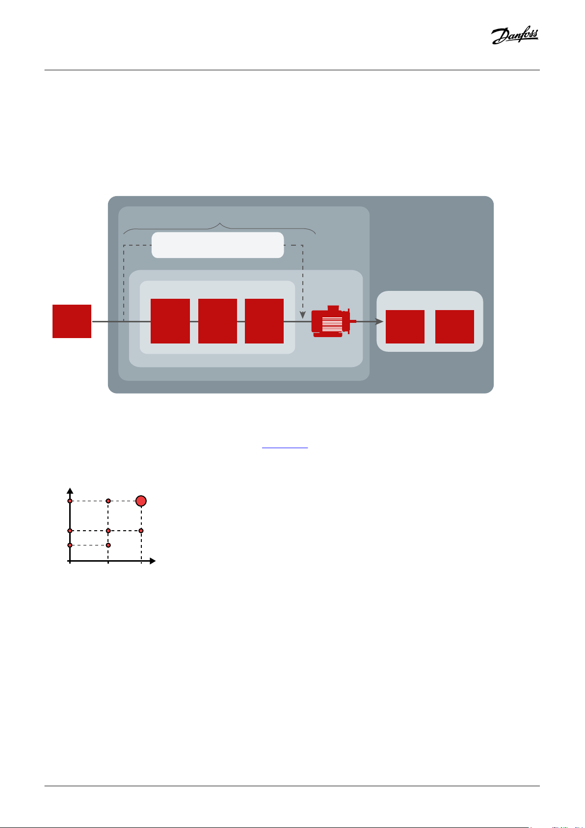
Terms like Complete Drive Module (CDM) and Power Drive Systems (PDS) are used to define the elements in the design. The objective
is to make more efficient and fewer energy consuming designs.
The CDM contains the drive controller as well as auxiliary devices and input components.
Illustration 6: Drive System Design
The efficiency classes IE0 to IE2 of the drive controller as specified in IEC 61800-9-2 (EN 50598-2) refer to the 90/100 operating point, i.e.
90 % motor stator frequency and 100% torque current (see illustration 7).
Illustration 7: Operating Point according to IEC 61800-9-2 (EN 50598)
Since in the future all component manufacturers will disclose their loss data according to this new standard, optimized applications
can be designed with a wide range of different components. The new Standard allows an accurate preliminary calculation of the power
losses, so that the ROI (Return of Investment) can be reliably determined. Up to now the overall efficiency of speed-regulated electric
motors was estimated with the aid of approximate energy consumption calculations.
It is now possible to determine the total losses of a system for the 8 operating points defined in the standard, including the part load
operation, via a simple addition of power losses. Danfoss helps its customers to avoid having to rely on system solution providers, to
ensure that their systems will retain a competitive advantage also in the future.
EC 61800-9-2 (EN 50598-2) shifts the focus from the individual component to the efficiency of the whole drive system. The new
efficiency classes (International Efficiency for Systems, IES)
24 | Danfoss A/S © 2019.10
AJ286655760917en-000101 / 130R0301
Page 25
Input power
e30bh443.10
Output power
Mains cabeling Input filters
Drive input
DC link
Drive output Output filters
Motor cables
and motor
Losses
Losses
Losses
Losses
Losses Losses Losses
Design Guide | VLT® AutomationDrive FC 301/302
VLT® Product Family Overview
allow a simple determination of the total losses for a whole drive system (PDS).
Danfoss offers the MyDrive® ecoSmart™ tool, which is available online or as a Smartphone app to assist with the efficiency calculation.
Use MyDrive® ecoSmart™ to:
• Look up part load data as defined in IEC 61800-9-2, for VLT® and VACON® drives
• Calculate efficiency class and part load efficiency for drives and power drive systems
• Create a report documenting part load loss data and IE or IES efficiency class.
For more information, refer to http://ecosmart.danfoss.com.
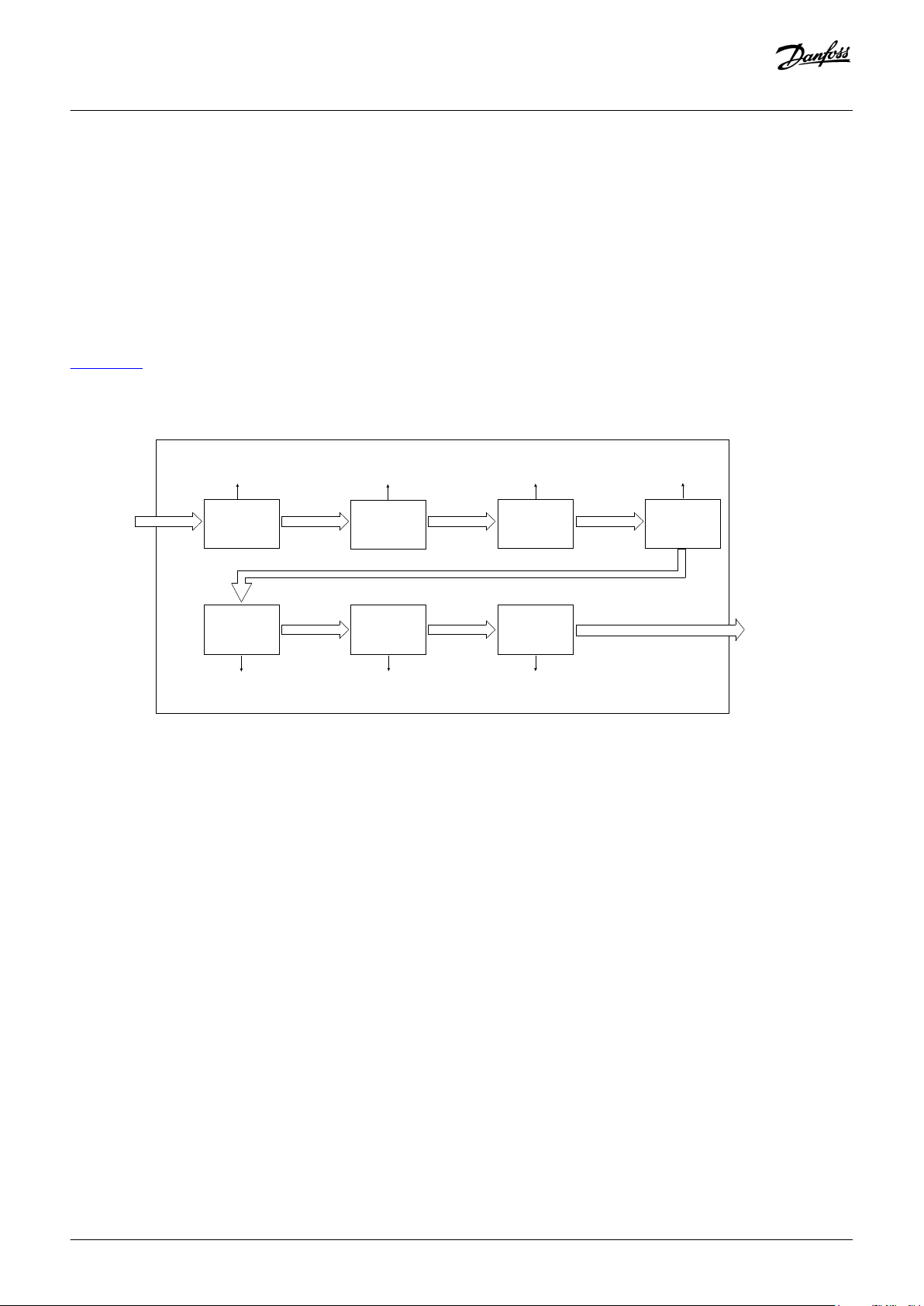
illustration 8 shows the components in the PDS which contribute to losses in the design. Mains cables and the load machine are not a
part of the PDS, even though their losses can be significant and could be a part of the evaluation of the overall energy efficiency of the
installation.
Illustration 8: Losses in a Power Drive System
4.3.1.1 Losses in Mains Cabling
The cabling from the supply must be considered, as the selection of suitable cables is often a problem, especially when dedicated
feeding transformers are installed. From the impedance of the cables, the energy losses are created in the ohmic part. Calculate the
active power losses for a 3-phase system with a star point groundingas follows:
P
L,mains
= 3 x R x I
2
L1
Because the load, when using drives and motors, also include reactive power and harmonic currents, these parameters also contribute
to losses. The ratio between active and apparent power is normally called the power factor. Having a PDS with a power factor close to 1
result in the lowest losses in the mains. Using filters on the input side of the drive can lower the power factor.
4.3.1.2 Input Filters: Line Reactors and Harmonic Filters
Line reactor
A line reactor is an inductor which is wired in series between a power source and a load. Line reactors, also called input AC reactors, are
typically used in motor drive applications.
Danfoss A/S © 2019.10
AJ286655760917en-000101 / 130R0301| 25
Page 26

Design Guide | VLT® AutomationDrive FC 301/302
The main function of the line reactor lies into its current limiting characteristics. Line reactors also reduce the main harmonics, limit the
inrush currents, and protect drives and motors. An overall improvement of the true power factor and the quality of the input current
waveform can be achieved.
When to use line reactors
It is important to consider the installation environment for the drives. In some situations, distortion from the grid can damage the drive
and precautions must be taken.
A simple menas of prevention is to ensure a minimum of impedance in front of the drive.
• The installation site has switched power factor correction capacitors.
• The installation site has lightening strikes or voltage spikes.
• The installation site has power interruptions or voltage dips.
VLT® Product Family Overview
Danfoss offers the line reactor program VLT® Line Reactor MCC 103, see
Harmonic filters
The purpose of using harmonic filters is to reduce the distortion on the mains. The distortion is generated by the drives when
switching the voltage to generate a frequency on the output. The harmonics should be limited both seen from energy consumption
perspective and disturbance of other users in the grid.
There are 2 categories of harmonic solutions:
• Passive.
• Active.
Passive solutions consist of capacitors, inductors, or a combination of both in different arrangements. The simplest solution is to add
inductors/reactors of typically 3–5% in front of the drive. This added inductance reduces the number of harmonic currents produced
by the drive. More advanced passive solutions combine capacitors and inductors in trap arrangement specially tuned to eliminate
harmonics starting from, for example, the 5th harmonic.
For more details on the Danfoss passive solutions, refer to VLT® Advanced Harmonic Filters AHF 005/AHF 010 Design Guide.
The active solutions determine the exact current that cancels the harmonics present in the circuit and synthesizes and injects that
current into the system. Thus, the active solution mitigates the real-time harmonic disturbances, which makes these solutions effective
at any load profile.
For more details on the Danfoss active solutions, refer to VLT® Low Harmonic Drive Operating Instructions, and VLT® Advanced Active
Filter AAF 006 Operating Instructions.
Danfoss.com.
4.3.1.3 Drive, Input Side
RFI (radio frequency interference)
Drives generate radio frequency interference (RFI) due to their variable-width current pulses. Drives and motor cables radiate these
components and conduct them into the mains system.
RFI filters are used to reduce this interference on the mains according to IEC 61800-3 in order not to disturb radio services. Maximum
allowed emission depends on the environment where the PDS is used.
The need for reducing the interferences and the losses created by the coils is a trade-off that is hard to influence in the use of drives.
Even though the losses exist, it is important to fulfill the legislation demands for the installation environment.
26 | Danfoss A/S © 2019.10
AJ286655760917en-000101 / 130R0301
Page 27

Design Guide | VLT® AutomationDrive FC 301/302
RFI filter on IT grid
If the drive is supplied from an isolated mains source (IT mains, floating delta) or TT/TN-S mains with grounded leg (grounded delta),
the RFI filter must be turned off.
In the OFF position, the internal capacitors between the chassis (ground), the input RFI filter, and the DC link are cut off. As the RFI
switch is turned off, the drive is not able to meet optimum EMC performance.
By opening the RFI filter switch, the ground leakage currents are also reduced, but not the high-frequency leakage currents caused by
the switching frequency of the drive. It is important to use isolation monitors that are designed for use with power electronics (IEC
61557-8). For example, Deif type SIMQ, Bender type IRDH 275/375, or similar.
The Danfoss VLT® drives can be ordered with different types of RFI filters. See more details on RFI, the use of RFI filters, and EMC
compliance in 10.16 Electromagnetic Compatibility (EMC) Overview.
Passive diode rectifier input
The use of diode rectifiers on the input side of the drives are the most cost-effective design. The energy flow goes from the mains to
the load and have low losses. On the other hand, diodes create harmonics in the mains when rectifying and thereby create losses.
These harmonics can be reduced by having DC-link coils, which are used in the Danfoss VLT® drives.
An energy flow from the drive back to the grid is not possible with this design as the energy is generated back from the application to
the DC link. Use a DC chopper and a connected resistor to absorb the energy. This reduces the energy efficiency significantly. If more
drives are installed, an improvement can be gained via load sharing by connecting the DC links, see
For information about the use of brake resistors for drives ordered with built-in brake choppers, refer to 10.10.1 Selection of Brake
Resistor and 10.10.2 Control with Brake Function.
VLT® Product Family Overview
10.3.4 Load Sharing Connection.
Active front end
In contrast to the diode rectifier, the active front end can generate excessive energy from the DC link back to the mains. In regenerative
applications, this design provides a significant improvement of the energy efficiency. This technology also has advantages in relation
to harmonics compensation and a more stable DC-link voltage. The design has similar functions on the input as on the output,
controlling IGBTs. There are also losses generated by switching of the IGBTs, which influence the energy efficiency. Due to the extra
IGBTs, this solution can be more expensive and is not used as often as the passive diode rectifier.
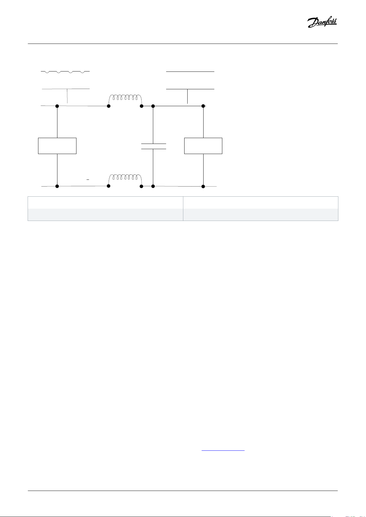
4.3.1.4 DC Link
The DC link is a power storage facility for the output section of the drive. There are 2 major components to the DC-link section:
• Capacitors
• Coils
In illustration 9 only 1 capacitor is shown, but it is always a series of capacitors.
Danfoss A/S © 2019.10
AJ286655760917en-000101 / 130R0301| 27
Page 28
1
3
+
+
2 4
e30bh114.10
Design Guide | VLT® AutomationDrive FC 301/302
VLT® Product Family Overview
1 Direct current (AC ripple)
3 Direct current
Illustration 9: Wiring Diagram of the DC Link
2 Rectifier
4 Inverter
With Danfoss VLT® drives, this intermediate section always uses DC coils, also known as DC line reactors or DC chokes. For cost
considerations, most other drive manufacturers do not offer these DC line reactors as standard equipment. Danfoss regards these coils
as essential for 2 main reasons:
• The ability to reduce harmonic noise (interference) by 40%.
• The ability to ride through a temporary loss of power. This allows the drive to avoid numerous unplanned shutdowns.
4.3.1.5 Drive, Output Side
The output side of the drive contains IGBTs used for generating a variable AC voltage with variable frequency. If no filters are used,
overvoltage spikes, due to reflection of the voltage waveform, can be measured on the motor connection. This situation is often linked
with long motor cables used in the installation and can reach values up to twice the level of the DC-link voltage.
From a user perspective, losses on the output side of the drive can be influenced by using a lower switching frequency, but this also
contributes to higher losses in the motor and filters installed. To optimize energy efficiency, a compromise must be found when
selecting the components used, for example, filters, motor type, and others. Often, output filters are used with the purpose of reducing
stress on the insulation.
In the following sections, the aspect of different filter types is discussed in perspective of energy efficiency versus function.
Common-mode filters
Common-mode HF filters are placed between the drive and the motor. They are nanocrystaline cores that mitigate high-frequency
noise in the motor cable (shielded or unshielded) and eliminate bearing currents, and hence Electro Discharge Machining (EDM) or
bearing etching in the motor. Bearing currents caused by drives are also referred to as common-mode currents.
Since the common-mode filters mitigate high frequency, these filters absorb energy and contribute also to losses. Here, the trade-off is
the advantage described compared with the losses.
More information on VLT® Common Mode Filters MCC 105 can be found on www.Danfoss.com.
28 | Danfoss A/S © 2019.10
AJ286655760917en-000101 / 130R0301
Page 29

Design Guide | VLT® AutomationDrive FC 301/302
dU/dt filters
At the IGBTs on the output switch, the voltage is not a clean sinus curve. It contains fast changes in voltage levels over a very short
time. The use of dU/dt filters increases the raise time of the motor voltage to reduce the stress on the motor insulation. If not avoided,
the problem will typically not show at once, but after some time, the insulation breaks and creates problems.
The switching frequency influences the losses in the dU/dt filters. These losses can be up to 1% of the rated power. Here, the trade-off
is the possible damage of the motor over time compared with the cost of energy losses.
Danfoss offers the VLT® dU/dt Filter MCC 102 as a possible solution. Find more information on www.Danfoss.com.
Sine-wave filters
A more advanced, but also more costly solution, is using sine-wave filters.
The VLT® Sine-Wave Filter MCC 101 is a differential-mode low-pass filter that suppresses the switching frequency component coming
from the drive and smoothes out the phase-to-phase voltage of the drive to become sinusoidal. This reduces the motor insulation
stress and bearing currents. By supplying the motor with a sinusoidal voltage waveform, the switching acoustic noise from the motor is
also eliminated.
For more detailed information, see the VLT® Sine-Wave Filter MCC 101 factsheet.
VLT® Product Family Overview
However, this type of filter also produces a voltage drop and there may be a reduction in the available control bandwidth. This can
sometimes make it impossible to use this filter type. Again, as for the dU/dt filter, losses are linked to the switching frequency.
For more detailed information, see the
VLT® Output Filters Design Guide.
4.3.1.6 Motor Cables and Motor
Motor cables
Motor cables introduce mainly ohmic losses: the longer the cables, the more resistance. In general, when correctly selected, the losses
in cables shorter than 25 m (82 ft) can be neglected. In single-wire cables with individual shielding, current causes losses in the cable
shielding. These losses can be neglected when using 3-wire cables.
Motor
There are many different types of motors that can be operated with a drive. The solution for dealing with losses in motors is therefore
depending on the individual motor type and installation. In standard IEC 61800-9-2:2017 annex D, a discussion on motor load and
losses is found.
A method to evaluate the losses generated in the motor operated with a drive can be found in the standards IEC 60034-2-1 and IEC TS
60034-2-4.
For the drive dealt with in this manual, find more information on supported motor types in 5.1.2 Supported Motor Types.
Danfoss A/S © 2019.10
AJ286655760917en-000101 / 130R0301| 29
Page 30

Design Guide | VLT® AutomationDrive FC 301/302
Product Overview
5 Product Overview
5.1 Overview of Drives Systems
Danfoss offers drives in different enclosure types for a wide range of applications.
Standalone AC drives
The Danfoss standalone AC drives are so robust that they can be mounted outside of cabinets virtually anywhere, even right beside the
motor. Equipped for the toughest of environment, they suit any application.
More uncompromising features:
• Enclosure sizes with protection ratings up to IP66/UL Type 4X.
• Full EMC compliance according to international standards.
• Ruggedized and coated PCBs.
• Wide temperature range, operating from -25 °C to +50 °C (-13 °F to 122 °F) without derating.
• Motor cable lengths up to 150 m (492 ft) shielded / 300 m (984 ft) unshielded as standard with uncompromised performance.
Enclosed drives
Danfoss drives are designed with the installer and operator in mind to save time on installation, commissioning, and maintenance.
VLT® enclosed drives are designed for full access from the front. After opening the cabinet door, all components can be reached
without removing the drive, even when mounted side by side.
Several cooling options, including back-channel cooling, provide optimum adaption to the installation location and application.
More time-saving features:
• An intuitive user interface with an award-winning local control panel (LCP) and common control platform that streamlines start-up
and operating procedures.
• Robust design and advanced controls make Danfoss drives virtually maintenance-free.
Modules
The compact design of the VLT® high-power drive modules makes them easy to fit even in small spaces. Integrated filters, options, and
accessories provide extra capabilities and protection without increasing the enclosure size.
More space-saving features:
• Built-in DC-link reactors for harmonic suppression eliminate the need for higher loss external AC line reactors.
• Optional built-in RFI filters are available throughout the power range.
• Optional input fuses and load share terminals are available within the standard enclosures.
• In addition to the many valuable features that the Danfoss drives offer as standard, there are several other control, monitoring, and
power options available in pre-engineered factory configurations.
For more details on the enclosure types, the modularity, and the applications, see the product-specific selection guides on
www.danfoss.com.
5.1.1 Filter Options
Filters are often extra components that must be planned for when designing the power drive system. It is important to understand
why and when to use output filters with Danfoss drives.
30 | Danfoss A/S © 2019.10
AJ286655760917en-000101 / 130R0301
Page 31

Design Guide | VLT® AutomationDrive FC 301/302
For more details on output filters, refer to Output Filters Design Guide.
Product Overview
5.1.1.1 Protection of Motor Insulation
The output voltage of the drive is a series of trapezoidal pulses with a variable width (pulse width modulation) characterized by a pulse
rise time, tr. When a transistor in the inverter switches, the voltage across the motor terminal increases by a dU/dt ration depending on:
• The motor cable (type, cross-section, length, shielded or unshielded, inductance, and capacitance).
• The high-frequency surge impedance of the motor.
Because of the impedance mismatch between the cable characteristic impedance and the motor surge impedance, a wave reflection
occurs, causing a ringing voltage overshoot at the motor terminals
5.1.1.2 Reduction of Motor Acoustic Noise
There are 3 main sources for generation of acoustic noise in the motor:
• The magnetic noise produced by the motor core through magnetostriction.
• The noise produced by motor bearings.
• The noise produced by motor ventilation.
When a motor is fed by a drive, the pulse-width-modulated (PWM) voltage applied to the motor causes extra magnetic noise at the
switching frequency and harmonics of the switching frequency (mainly the double of the switching frequency). In some applications,
this is not acceptable. To eliminate this additional switching noise, use a sine-wave filter. This filter filters the pulse-shaped voltage
from the drive and provides a sinusoidal phase-to-phase voltage at the motor terminals.
5.1.1.3 Reduction of High-frequency Electromagnetic Noise in Motor Cables
Using filters reduces noise generated in the motor cables.
When no filters are used, the ringing voltage overshoot that occurs at the motor terminals is the main high-frequency noise source. The
noise can be explained by the correlation between the frequency of the voltage ringing at the motor terminals and the spectrum of
the high-frequency conducted interference in the motor cable. Besides this noise component, there are also other noise components
such as:
• The common-mode voltage between phases and ground at the switching frequency and its harmonics - high amplitude but low
frequency.
• High-frequency noise (above 10 MHz) caused by the switching of semiconductors - high frequency but low amplitude.
Installing an output filter gives the following advantages:
• dU/dt filters reduce the frequency of the ringing oscillation to a level below 150 kHz.
• Sine-wave filters eliminate the ringing oscillation and the motor receives a sinusoidal phase-to-phase voltage.
5.1.1.4 Bearing Currents and Shaft Voltage
Fast switching transistors in the drive combined with an inherent common-mode voltage (voltage between phases and ground)
generate high-frequency bearing currents and shaft voltages. While bearing currents and shaft voltages can also occur in direct-on-line
motors, these phenomena are accentuated when the motor is fed from a drive.
Danfoss A/S © 2019.10
AJ286655760917en-000101 / 130R0301| 31
Page 32

Design Guide | VLT® AutomationDrive FC 301/302
Most bearing damage in motors fed by drives is caused by vibrations, misalignment, excessive axial or radial loading, improper
lubrication, and impurities in the grease. Sometimes, bearing damage is caused by bearing currents and shaft voltages. The
mechanism that causes bearing currents and shaft voltages is complicated to explain, but it is important to know that it exists. Two
main mechanisms can be identified:
• Capacitive coupling: The voltage across the bearing is generated by parasitic capacitances in the motor.
• Inductive coupling: Caused by circulating currents in the motor.
The grease film of a running bearing behaves like isolation. The voltage across the bearing can cause a breakdown of the grease film
and produce a small electric discharge (a spark) between the bearing balls and the running track. This discharge produces a
microscopic melting of the bearing ball and running track metal and over time it causes the premature wear-out of the bearing. This
mechanism is called electrical discharge machining (EDM).
Product Overview
5.1.2 Supported Motor Types
Today, the drive-controlled, 3-phase motor is a standard element in all automated applications. High-efficiency induction motors, but
also motor designs such as permanent magnet motors, EC motors, and synchronous reluctance motors, need regulation with AC
drives. Many motors cannot be operated directly from the 3-phase standard power supply.
The Danfoss VLT® drives can control multiple motor technologies. The most advanced is the VLT® AutomationDrive FC 302. This drive is
compatible with virtually all types of common AC motor technologies on the market:
• Induction motors (IM).
• Surface permanent magnet motors (SPM).
• Interior permanent magnet motors (IPM).
• Synchronous reluctance motors (SynRM).
• Permanent magnet assisted synchronous reluctance motors (PMaSynRM).
Induction motors, synchronous motors, and induction servo motors are all supported as standard without the need for extra software.
The FC 302 can control the motors in either open loop or closed loop through its high precision motor control platform, VVC+ or flux
control.
Standard IEC line motors (IEC 60034-30-1)
The standard IEC 60034-30-1 of March 2014 replaces the standard 60034-30:2008, which has defined 3 efficiency levels for 3-phase
induction motors. The updated standard IEC 60034-30-1 now includes the 4th efficiency level, IE4. Furthermore, 8-pole motors and an
extended power range are now included in the standard.
Efficiency classes:
In the IEC 60034-30-1, the following efficiency classes are defined for induction motors:
• IE1 (Standard efficiency).
• IE2 (High efficiency).
• IE3 (Premium efficiency).
• IE4 (Super premium efficiency).
IE = Internation efficiency.
These motor types can all be operated with Danfoss VLT® drives.
More information on this topic can be found in the publication Motor Technologies for Higher Efficiency in Applications. This
document can be downloaded from
www.danfoss.com.
32 | Danfoss A/S © 2019.10
AJ286655760917en-000101 / 130R0301
Page 33

e30bh117.10
Design Guide | VLT® AutomationDrive FC 301/302
Product Overview
5.1.3 Bearing Currents
Protecting the motor insulation and bearings
The drive employs modern IGBT inverter technology. Regardless of the frequency, the drive output comprises pulses of approximately
the drive DC bus voltage with a very short rise time. The pulse voltage can almost double at the motor terminals, depending on the
attenuation and reflection properties of the motor cable and the terminals. This can cause extra stress on the motor and motor cable
insulation. Modern AC drives with their fast-rising voltage pulses and high-switching frequencies can generate current pulses that flow
through the motor bearings. Gradually, these current pulses can erode the bearing races and rolling elements. Optional dU/dt filters
protect the motor insulation system and reduce bearing currents. Optional common-mode filters mainly reduce bearing currents.
Insulated N-end (non-drive end) bearings protect the motor bearings.
Practical tips
Usually, the shielding surface of the motor cable is connected to the frame of the terminal box and not to the motor stator frame.
However, the motor terminal box on some motors can be mounted to the stator housing with a considerable change of the highfrequency currents and impedance. Typically, there is a gasket between the terminal box and the stator frame, and the box is attached
to the motor frame with 4 small screws. Conducted measurements on these motors showed that screws did not provide a low
impedance from the terminal box to the stator and therefore, the common-mode currents were oscillated with a noticeable
magnitude.
Applying high-frequency bonding straps between the motor terminal box and the stator frame helps providing low impedance for
high-frequency currents and therefore eliminating the common-mode current oscillations in the installation.
Illustration 10: Installation of EMC straps from the Terminal Box to the Motor Frame
Sometimes, so called NYCWY cables are used to connect the motor to the drive inverter. The symmetry of the PE conductor in these
cables is achieved by a conductor surrounding all the phase leads. These cables, however, prevent common-mode currents at the
fundamental frequency only.
To avoid common-mode currents at fundamental and high frequencies at the same time, use multicore symmetric motor cables with 3
ground conductors with a shield.
Applying common-mode cores
Common-mode cores across motor cable conductors effectively reduce high-frequency motor bearing currents. On motors with a
power rating of approximately 100 kW and onwards, the result of reduction of bearing currents is most evident.
Danfoss A/S © 2019.10
AJ286655760917en-000101 / 130R0301| 33
Page 34

PE U V W
e30bd839.10
Design Guide | VLT® AutomationDrive FC 301/302
Product Overview
High-frequency common-mode cores may have an oval or round shape and they are easy-to-install components.
Install common-mode cores in a way that only unshielded power cores of the motor cable are wired through the core. The PE and
shielding wires must be placed outside of the core. It is also important that all 3 motor phase wires are wired through the same core.
Otherwise, the cores do not provide the required functionality.
Illustration 11: Installing Common-mode Cores
Depending on the power rating of the drive installation and the quantity of motor cables connected in parallel, several same-size
common-mode cores might be used. In dedicated product manuals, preselection tables advise on the required minimal quantity of
single common-mode cores to install. The number of cores depend on the power rating, the nominal voltage of the drive installation,
and the length of the applied motor cables.
Applying common-mode cores on motor cables connected in parallel
If many motor cables connected in parallel are used and the power wires of all cables cannot be fitted through the common-mode
cores, place the required number of cores on each individual motor cable. This ensures the saturation of the core due to likely unequal
current sharing between cables. Wire all 3-phase conductors of each cable through 1 set of cores.
34 | Danfoss A/S © 2019.10
AJ286655760917en-000101 / 130R0301
Page 35

Ferrite rings
Metallic
cabinet wall
Shield connected
to ground
Motor cable
PE
Mains cable
High-frequency
grounding
Motor cable
Ferrite rings
Metallic
cabinet wall
Shield connected
to ground
e30bg998.11
e30bh118.10
Design Guide | VLT® AutomationDrive FC 301/302
Product Overview
Illustration 12: Installation of CM Cores on Cables Connected in Parallel
As losses of common-mode cores are low, the expected temperature of the core is below 60 °C (140 °F) under normal circumstances.
Thus common-mode cores can also be accommodated inside the motor terminal box. If cores cannot be fitted inside the drive housing
or the motor terminal box, they can be placed in an external cabinet close to the motor.
Illustration 13: Mounting of CM Cores Inside the Motor Terminal Box
To ensure minimal bearing currents in the motor, Danfoss recommends ordering the drive with output motor filters as a power option.
Danfoss A/S © 2019.10
AJ286655760917en-000101 / 130R0301| 35
Page 36

Design Guide | VLT® AutomationDrive FC 301/302
Product Overview
5.2 Integrated Motion Controller
NOTICE
The integrated motion control is only available with special IMC software version 48.XX. To order the drive with the IMC
software, use the type code with software release version S067.
The integrated motion controller (IMC) enables position control with all motor control principles and motor types with and without
feedback.
To activate the IMC functionality, select [9] Positioning or [10] Synchronization in parameter 1-00 Configuration Mode. IMC enables the
following functions:
• Positioning: Absolute, relative, and touch probe.
• Homing.
• Position synchronization.
• Virtual master.
Position control in both positioning and synchronization modes can be either sensorless or with feedback. In the sensorless control
principle, the motor angle calculated by the motor controller is used as feedback. In the closed-loop control principle, VLT®
AutomationDrive FC 302 supports most standard incremental encoders, absolute encoders, and resolvers. The position controller can
handle both linear and rotary systems. The controller can scale positions to any relevant physical unit such as mm or degrees.
5.2.1 Positioning, Homing, and Synchronization
5.2.1.1 Positioning
The drive supports relative positioning and absolute positioning. A positioning command requires 3 inputs:
• Target position.
• Speed reference.
• Ramp times.
The 3 inputs can come from various sources, see illustration 14.
36 | Danfoss A/S © 2019.10
AJ286655760917en-000101 / 130R0301
Page 37

+
e30be774.11
Par. 3-20 Preset target positions
Fieldbus reference 1 or pos. REF
Par. 3-16 Reference resource 2
Par. 3-17 Reference resource 3
Par. 3-03 Default speed
Fieldbus reference 1
Par. 3-15 Reference resource 1
Ramp settings:
Parameter groups 3-4* – 3-7*
Target position
Speed ref.
Acceleration/Deceleration
Profile generator
Commanded position
Speed
Acceleration
Design Guide | VLT® AutomationDrive FC 301/302
Product Overview
Illustration 14: Positioning References
In each control cycle (1 ms), the profile generator calculates position, speed, and acceleration required to do the specified movement.
The outputs from the profile generator are used for the position and speed controller.
5.2.1.2 Homing
Homing is required for creating a reference to the physical machine position in closed-loop control principle with incremental encoder
or in sensorless control principle. IMC supports various homing functions with or without a homing sensor. Select the homing function
in parameter 17-80 Homing Function. After selecting a homing function, complete homing before executing absolute positioning.
5.2.1.3 Synchronization
In synchronization mode, the drive follows the position of a master signal. The master signal and the offset between the master and
the slave are handled as shown in illustration 15.
Danfoss A/S © 2019.10
AJ286655760917en-000101 / 130R0301| 37
Page 38

Position ref.
Acceleration/Deceleration
Speed ref.
Fieldbus Sync. REF
Master position
Par. 3-16 Reference Resource 2
Par. 3-26 Position Offset
Par. 3-02 Offset Speed
Ramp Settings:
Parameter groups 3-4* - 3-7*
e30be775.11
Profile generator
Commanded
position
Speed
Acceleration
Offset handling
Synchronization:
Par. 3-22 - 3-25,
7-97,7-99
Control word
Target Position
16 bit
e30bg868.11
PCD 0 PCD 1
PCD 2 PCD 3 PCD X
Control word
Speed Reference
+/- 4000Hex
Target Position
32 bit
e30bg869.11
PCD 0 PCD 1
PCD 2 PCD 3 PCD X
Design Guide | VLT® AutomationDrive FC 301/302
Product Overview
Illustration 15: Synchronization References
In each control cycle (1 ms), the profile generator calculates position, speed, and acceleration required to do the specified movement.
The outputs from the profile generator are used as inputs for the position and speed controller.
5.2.1.4 Fieldbus References
Fieldbus references for speed and position are set via the process data (PCD) configuration as shown in the example:
Illustration 16: Positioning: Default settings (PCD 1 = Fieldbus REF 1)
Illustration 17: Positioning: PCD write configuration PCD 1 = Fieldbus REF 1, PCD 2 and 3 = Fieldbus Pos REF
38 | Danfoss A/S © 2019.10
AJ286655760917en-000101 / 130R0301
Page 39

Control word
Master position
e30bg870.11
PCD 0 PCD 1
PCD 2 PCD 3 PCD X
Commanded
Position
Speed
+
Speed Limit
Max
Min
Accel. limit
+
Par. 7-99
Par. 4-1*
7-9*
Position
PI Ctrl.
Par. 7-98
Position
PI
Feed
Par.7-90 Position PI
Feedback Source
Par. 7-00 Speed PID
Feedback Source
7-0*
Speed PID
Par. 7-08
Speed PID
Accel. Feed forward
factor
Flux motor
control
Ramp
Torque
Acceleration
Par.1-69 System Inertia
e30be776.10
Profile
Generator
Design Guide | VLT® AutomationDrive FC 301/302
Product Overview
Illustration 18: Synchronizing: PCD write configuration PCD 1 = Fieldbus Sync REF
5.2.2 Control
5.2.2.1 Control Loops
In positioning and synchronization mode, 2 extra control loops control the motor in addition to the motor controller running flux
control principle, sensorless, or with motor feedback. The position PI controller is the outer loop providing the setpoint for the speed
PID, which provides the reference for the motor controller. For a closed loop, feedback source can be selected individually for each of 3
controllers.
For sensorless control principle, select [0] Motor feedb. P1-02 in the following parameters:
• Speed PID: Parameter 7-00 Speed PID Feedback Source.
• Position PI: Parameter 7-90 Position PI Feedback Source.
With this set-up, both controllers use the motor angle calculated by the motor controller. See
parameters affecting the control behavior.
Illustration 19: Positioning and Synchronization Mode
illustration 19 for control structure and
Danfoss A/S © 2019.10
AJ286655760917en-000101 / 130R0301| 39
Page 40

Design Guide | VLT® AutomationDrive FC 301/302
5.2.2.2 Control and Status Signals
IMC control and status signals are available I/O bits and fieldbus bits.
Table 7: Control and Status Signals
Product Overview
Name Function Digital
input
(1)
Control
word
Digital
output
Control signals
Enable master offset Activates the master offset when parameter 17-93 Mas-
x x –
ter Offset Selection is set to options [0]–[5].
Start homing Starts selected homing function. x x – –
Start virtual master Starts the virtual master. x x – –
Activate touch Selects touch probe positioning mode. x x – –
Relative position Selects between absolute and relative positioning. x x – –
Enable reference Starts selected motion. x x – –
Sync. to position
Selects positioning in synchronizing mode. x x – –
mode
Home sensor Selects input for home sensor. x x – –
Home sensor inverse Selects input for home sensor. x – – –
Touch sensor Selects input for touch probe sensor. x x – –
Touch sensor inverse Selects input for touch probe sensor. x – – –
Speed mode Selects speed mode when parameter 1-00 Configura-
x x – –
tion Mode is set to [9] Positioning or [10] Synchronization.
Status
word
Target inverse Changes the sign of the set target position. For exam-
x x – –
ple, if the set target is 1000, the activation of this option changes the value to -1000.
Status signals
Reverse after ramp Indicates the sign of speed reference after the ramp. – – x –
Virtual master dir. Controls the direction of slaves. – – x –
Homing OK Homing is completed with the selected homing func-
– – X X
tion.
On target Positioning: Target position reached.
– – x x
Synchronization: Slave position aligned with master
position.
Position error Maximum position error exceeded. – – x x
Position limit A position limit is reached (parameter 3-06 Minimum
– – x –
Position or parameter 3-07 Maximum Position).
Touch on target Target position is reached in touch probe position
– – x x
mode.
Touch activated Touch probe positioning active. – – x x
40 | Danfoss A/S © 2019.10
AJ286655760917en-000101 / 130R0301
Page 41

Design Guide | VLT® AutomationDrive FC 301/302
1
For best accuracy, use fast digital inputs 18, 32, and 33 for home and touch probe sensors.
Product Overview
When [3] FC Motion Profile is selected in parameter 8-10 Control Word Profile, the bits in the control word and the status word have the
following meaning:
Table 8: Control Word
Bit 0 1
0 Preset reference LSB –
1 Preset reference MSB –
(1)
2
Preset reference EXB –
3 Coast stop No coast stop
4 Quick stop No quick stop
(1)
5
No reference Enable reference
6 Ramp stop Start
7 No reset Reset
8 No jog Jog
(1)
9
Absolute Relative
10 Data not valid Data valid
11
12
(1)
(1)
No homing Start homing
No touch Activate touch
13 Set-up select LSB –
14 Set-up select MSB –
15 No reversing Reversing
1
Different from [0] FC Profile. Options for bits 0–2, and 12–15 in parameter 8-14 Configurable Control Word CTW:
• [11] Start Homing
• [12] Activate Touch Probe
• [13] Sync. to Pos. Mode
• [14] Ramp 2
• [15] Relay 1
• [16] Relay 2
• [17] Speed Mode
• [18] Start Virtual Master
• [19] Activate Master Offset
• [20] Target Inverse
• [26] Home Sensor
• [27] Touch Sensor
Danfoss A/S © 2019.10
AJ286655760917en-000101 / 130R0301| 41
Page 42

Design Guide | VLT® AutomationDrive FC 301/302
Table 9: Status Word
Bit 0 1
0 Control not ready Control ready
1 Drive not ready Drive ready
2 Coasting Enable
3 No error Trip
(1)
4
5 Reserved Reserved
6 No error Trip lock
7 No warning Warning
(1)
8
9 Local operation Bus control
10 Out of frequency limit Frequency limit OK
11 No operation In operation
Not homed Home done
Not on target position Target position reached
Product Overview
12 Drive OK Stopped, auto start
13 Voltage OK Voltage exceeded
14 Torque OK Torque exceeded
15 Timer OK Timer exceeded
1
Different from [0] FC Profile. Options for bits 5 and 12–15 in parameter 8-13 Configurable Status Word STW:
• [4] Position Error
• [5] Position Limit
• [6] Touch on Target
• [7] Touch Activated
5.3 Functional Safety
5.3.1 Protection of Personnel and Equipment
Danfoss AC drives offer functional safety solutions for smart machine design. The VLT® AutomationDrive has Safe Torque Off (STO)
built-in as standard. Along with other safety functions, STO enhances application safety. The drive-based functional safety offering
complies with the requirements of international standards and requirements, including European Union Machinery Directive
2006/42/EC.
The STO function complies with ISO 13849-1-PL d and SIL2 according to IEC 61508/IEC 62061. With the VLT® Safety Option MCB 150
Series, this safety function can be extended to include SS1, SLS, SMS, safe jog mode, and more. The speed monitoring functions are
available both with and without speed feedback.
5.3.2 VLT® Safety Option MCB 150 and MCB 151
42 | Danfoss A/S © 2019.10
AJ286655760917en-000101 / 130R0301
Page 43

e30bh408.10
n
0
t
Function requested
Design Guide | VLT® AutomationDrive FC 301/302
The MCB 150 and MCB 151 can be integrated directly in the AC drive and is prepared for future connection to common safety bus
systems. The module is certified according to ISO 13849-1 up to PL d and IEC 61508/IEC 62061 up to SIL 2, and provides SS1, SLS, and
SMS functionality according to IEC 61800-5-2. The option can be used in low- and high-demand applications. SS1 offers ramp- and
time-based functionality. SLS can be configured both with and without ramp-down on activation. SMS can be activated continously
without having a safe input.
Product Overview
5.3.3 VLT® Sensorless Safety MCB 159
When VLT® Safety Option MCB 151 is combined with the built-in VLT® Sensorless Safety MCB 159 option, an external sensor is no
longer required for safe speed monitoring.
5.3.4 VLT® Safety Option MCB 152
The VLT® Safety Option MCB 152 operates the safety function of an AC drive via the PROFIsafe fieldbus combined with the VLT®
PROFINET MCA 120 fieldbus option. Central and decentral drives at different machinery cells can easily be interconnected with the
PROFIsafe safety fieldbus. The interconnection enables activation of the STO irrespectively of where a hazard occurs. The safety
functions of the MCB 152 are implemented according to EN IEC 61800-5-2. Two configurable safe digital inputs are available for
extension of safe I/Os.
The MCB 152 supports PROFIsafe functionality to activate integrated safety functions of the Danfoss from any PROFIsafe host up to
Safety Integrity Level SIL 2 according to EN IEC 61508 and EN IEC 62061, Performance Level PL d, Category 3 according to EN ISO
13849-1.
5.3.5 Safety Functions
5.3.5.1 Safe Torque Off (STO)
STO is the required base for drive-based functional safety as defined per EN IEC 61800-5-2, as the STO function brings the drive safely
to a no-torque state. STO is typically used for preventing an unexpected start-up (EN 1037) of machinery, or for an emergency stop
fulfilling stop category 0 (EN 60204-1).
When STO is activated, it immediately switches off the drive output to the motor. Motor speed then coasts to a stop.
Illustration 20: Motor Speed Coasts to Stop After Activation of STO
Danfoss A/S © 2019.10
AJ286655760917en-000101 / 130R0301| 43
Page 44

e30bh409.10
n
0
t
Function requested
e30bh410.10
n
0
t
Function requested
Design Guide | VLT® AutomationDrive FC 301/302
Product Overview
5.3.5.2 Safe Stop 1 (SS1)
The Safe Stop 1 function stops the motor safely by using a controlled ramp stop and then activating the STO function. SS1 is typically
used in applications like rolling mills where motion must be stopped in a controlled manner before switching to a no-torque state. In
addition to a safe process stop, SS1 can be used to implement an emergency stop, fulfilling category 0 (EN 60204-1).
Illustration 21: Motor Speed Ramps Down to Standstill, SS1 then Activates STO
5.3.5.3 Safely Limited Speed (SLS)
The Safely Limited Speed function prevents motors from exceeding a defined speed limit. If the speed limit is exceeded, SLS activates
the STO function, which stops the drive. The SLS safety function can be used in applications such as decanters, mixers, conveyors, or
paper machines where excess speed can be hazardous during certain operations like maintenance or cleaning.
Illustration 22: SLS Monitoring Motor Speed
5.3.5.4 Safe Maximum Speed (SMS)
The SMS is a variant of the SLS safety function. It provides continuous protection against a motor exceeding a defined maximum speed
limit. When SMS is used, it continuously monitors the motor speed. It is often used for centrifuges.
44 | Danfoss A/S © 2019.10
AJ286655760917en-000101 / 130R0301
Page 45

e30bh411.10
n
0
t
e30bb890.14
P1 P2 P3
Design Guide | VLT® AutomationDrive FC 301/302
Illustration 23: SMS Ensuring that the Speed Limit is not Exceeded
Product Overview
5.3.5.5 PROFIsafe
As a software feature, PROFIsafe covers safety applications utilizing PROFIBUS and PROFINET in process and factory automation. The
PROFIsafe protocol is suitable for both PROFIBUS and PROFINET networks without impacting the existing fieldbus standard. The
protocol is also approved for wireless transmission channels such as Bluetooth and Wi-Fi.
5.4 Danfoss VLT® FlexConcept®
Modern manufacturing plants need higher efficiency, more flexibility, and greater reliability in their drive systems than ever before - all
necessary to reduce manufacturing costs.
To meet that need, Danfoss has developed the VLT® FlexConcpet® - a modern, contemporary drive system using modern motor
technology, combined with the most advanced inverter drives and developed as a unified system.
Danfoss VLT® FlexConcept® offers a flexible selection of drives for centralized location in control rooms or decentral units for mounting
close to, or even on, the drive motors, giving greater flexibility in plant design and maintenance.
Danfoss VLT® FlexConcept® is an energy-efficient, flexible, and cost-efficient drive solution, mainly for conveyors. The concept consists
of the VLT® OneGearDrive driven by the VLT® AutomationDrive FC 302 or VLT® Decentral Drive FCD 302.
VLT® OneGearDrive is a permanent magnet motor with a bevel gear. The bevel gear can be delivered with different gear ratios.
Illustration 24: VLT® OneGearDrive
The VLT® OneGearDrive can be driven by VLT® AutomationDrive FC 302 and VLT® Decentral Drive FCD 302 in the following power sizes
depending on demands of the actual application:
Danfoss A/S © 2019.10
AJ286655760917en-000101 / 130R0301| 45
Page 46

Design Guide | VLT® AutomationDrive FC 301/302
• 0.75 kW (1.0 hp).
• 1.1 kW (1.5 hp).
• 1.5 kW (2.0 hp).
• 2.2 kW (3.0 hp).
• 3.0 kW (4.0 hp).
When parameter 1-10 Motor Construction is set to [1] PM, Non-salient SPM in either FC 302 or FCD 302, the VLT® OneGearDrive can be
selected in parameter 1-11 Motor Model. The recommended parameters are set automatically.
For further information, refer to the VLT® AutomationDrive FC 301/FC 302 Programming Guide, the VLT® OneGearDrive Selection
Guide, and http://files.danfoss.com/download/Drives/DKDDPB86A202_FlexConcept_LR.pdf.
Product Overview
5.5 Torque Sharing/Droop
Use the droop function when load distribution between drives connected to the same load is required. For example, in multi-motor
operation for anchor winches, cranes, and conveyors.
Many large winches, cranes, or conveyors have to be powered by 2 or more motors. If 1 fails, the others can handle the load (if the
drives are sufficiently oversized). The motors are usually connected to 2 or more drives to ensure that the application runs smoothly. By
using the droop function in the drive, it ensures, for example, that the winch motors create an equal torque at any speed and any load.
Only 1 drive is thus required to control the winch.
Torque sharing
• More than 1 motor on the same shaft - need for torque sharing.
• Designed for flux open-loop control/closed-loop control.
• Stiffness is configured in parameter 1-62 Slip Compensation or parameter 7-01 Speed PID Droop (compensation).
Benefits:
• Single setup.
• No master/slave, all are programmed as master, no communication needed between masters.
• Less inertia in more small motors compared with 1 large motor.
46 | Danfoss A/S © 2019.10
AJ286655760917en-000101 / 130R0301
Page 47

e30bh198.10
Design Guide | VLT® AutomationDrive FC 301/302
Product Overview
Illustration 25: Example of Torque Sharing
Commissioning of torque sharing drives
• Run drive in flux open-loop control/closed-loop control.
• Run drive in speed mode.
• Set negative value in parameter 1-62 Slip Compensation.
• Use same speed reference, start, and stop signals in all torque sharing drives.
• All torque sharing drives use the same parameters.
Example:
4-pole motor, nominal speed 1430 RPM ⇒ slip = 70 RPM at full load. If the reference is set to 1500 RPM and parameter 1-62 Slip
Compensation is set to -50%, the motor runs 1465 RPM at full load.
• Torque sharing also work in overload situation.
• Torque sharing also works with different motors (not with same value in parameter 1-62 Slip Compensation). Use parameter 7-01
Speed PID Droop with the same values.
5.6 Power Limit Function
A power limit function limits the power distributed to the motor (power limit motor mode). Also, the power limit function can limit
generative power fed back into the mains supply (AFE) or fed to a brake resistor (power limit generator mode). The power limit
function is designed for flux open-loop control/closed-loop control and can be used for all motor types with flux control core (ASMPM).
To activate the power limit, use a digital input or a fieldbus control word. To adjust the power limit level, use an analog input and/or
fieldbus PCD channel.
Danfoss A/S © 2019.10
AJ286655760917en-000101 / 130R0301| 47
Page 48

3x368 kVA
Generators
400 V, 50 Hz, 3 ph
Cos Ø = 0.9
G1 G2 G3
Shore
supply
Battery
bank
350 kWh
Ships
service
Variable
speed
drives
~ ~
~ ~
= =
= =
DC link DC link
M1
M2
375 kW
0–615 RPM
375 kW
0–615 RPM
375 kW
375 kW
Prop 1 Prop 2
Ships
service
Battery
bank
350 kWh
Emer
Sn/bd
e30bh199.10
Design Guide | VLT® AutomationDrive FC 301/302
Torque [Nm] = Power [W]/Speed [rad/sec]
The power limit function is activated and used in the following modes:
• Power limit always active (enabled).
• Power limit only when activated.
• Fixed power variable torque.
• Reduced power reduced speed (motor mode).
Product Overview
Illustration 26: Diagram of the Power Limit Function
The basic settings for the power that should be limited can be programmed via parameter settings. When power limit is active,
parameter 4-82 Power Limit Motor Mode and parameter 4-83 Power Limit Generator Mode are used as limits. The drive then calculates the
required torque levels to achieve a power limitation for motor/generator operation The motor speed is controlled so that the power
limit values are not exceeded. When operating in power limit mode, the motor speed can deviate from the actual speed setpoint that
is commanded.
One of the most common use cases for a power limit functionality is marine applications, such as winch and thruster applications, but
the function can be used in all types of applications. On board a ship/vessel, the mains supply is always coming from a generator
system. In many cases, several generators supply the total electrical load on the ship/vessel. If 1 of these generators fails/trips, the total
power requirement cannot be fulfilled anymore. To insure availability fo critical parts of the application, a limited power consumption
could keep the installation available and prevent the remaining generators from being instantly overloaded. The application can
remain running when a power limit function is activated because the power is kept within the defined limits.
48 | Danfoss A/S © 2019.10
AJ286655760917en-000101 / 130R0301
Page 49

Design Guide | VLT® AutomationDrive FC 301/302
Product Overview
5.7 Service Log
The service log is a data logger extension (alarm data saved in drive memory and exportable to VLT® Motion Control Tool MCT 10). If
certain alarms occur, the system saves a detailed log in 5 s increments.
Service technicians can analyze this information to troubleshoot and optimize the drive.
The drive saves up to 24 service log records in the flash memory. If the RTC (real-time clock) has been set in the drive, all errors and log
files are date- and time-stamped.
The relevant service log file can then be analyzed as a scope in MCT 10. Danfoss specifies the channels. All scope functions such as
Auto-scale and Diagnostics can be used. The HEX ad binary value can be shown, which also helps with the analysis.
Table 10: Alarms Triggering a Service Log Record
Alarm Alarm log data Parameter number
1 Time of trip (1 of the values):
• Priority RTC (if available).
• Priority operating time (if RTC is not available).
2 Alarm code Parameter 15-30 Fault Log: Error Code
3 Frequency Parameter 16-13 Frequency
4 Speed (RPM) Parameter 16-17 Speed [RPM]
5 Reference % Parameter 16-02 Reference %
7 DC-link voltage Parameter 16-30 DC Link Voltage
9 Motor phase U current Parameter 16-45 Motor Phase U Current
10 Motor phase V current Parameter 16-46 Motor Phase V Current
11 Motor phase W current Parameter 16-47 Motor Phase W Current
12 Motor phase voltage Parameter 16-12 Motor Current
15 Control word Parameter 16-00 Control Word
16 Status word Parameter 16-03 Status Word
Application-dependent trips/alarms such as Safe Torque Off (STO), do not trigger a service log record.
Sampling rate
Parameter 0-89 Date and Time Readout or parameter 15-32 Fault Log:
Time
There are 2 periods with different sampling rates:
• Slow samples: 20 samples at a rate of 250 ms resulting in 5 s of history before the trip.
• Fast samples: 50 samples at a rate of 5 ms resulting in 250 ms of detailed history before the trip.
5.8 Maintenance Functions
Danfoss VLT® drives feature preventive and condition-based monitoring functions.
Danfoss A/S © 2019.10
AJ286655760917en-000101 / 130R0301| 49
Page 50

Design Guide | VLT® AutomationDrive FC 301/302
Product Overview
5.8.1 Preventive Maintenance
Schedule maintenance based on a running hours counter. When planned maintenance occurs, the drive shows a message. Action flags
can be transferred via fieldbus. Parameter group 18-0* Maintenance Log contains the last 10 preventive maintenance events.
Maintenance log 0 is the latest log and maintenance log 9 is the oldest.
Parameters 18-00 to 18-03 show the maintenance item, the action, and the time of the occurrence.
The alarm log key gives access to both alarm log and maintenance log.
5.8.2 Condition-based Monitoring
The function uses the drive as a smart sensor for monitoring the condition of the motor and application. The VLT® AutomationDrive FC
302 features licensed functions that enforce predictive maintenance actions, such as:
• Motor stator winding monitoring.
• Vibration monitoring.
• Load envelope monitoring.
Set various thresholds and determine the baseline with different methods according to relevant standards and guidelines such as the
ISO 13373 standard for Condition Monitoring and Diagnostics of Machines or the VDMA 24582 guideline for condition monitoring.
The condition-based maintenance parameters are in parameter group 45-** Condition Based Monitoring.
5.8.2.1 Motor Stator Winding Monitoring
Motor winding failures lead to stop of operation and, thus, unwanted downtime. Motor winding failures start with a short circuit
between 2 windings. Over time, the short circuit leads to a motor short circuit fault. By using the motor stator winding monitoring
function, motor isolation faults are detected at an early stage, allowing maintenance of the motor before the winding fails entirely due
to overheating.
• By analyzing the motor current signature, the drive detects motor winding damage at an early stage.
• The function does not require any external sensors.
• The drive sends a warning/alarm to the LCP or fieldbus.
5.8.2.2 Vibration Monitoring
The VLT® AutomationDrive FC 302 can be used with an external vibration transducer (velocity or acceleration type 4–20 mA) to
monitor the vibration level in a motor or application. The available functions are baseline measurement, broadband trending, vibration
during acceleration and deceleration, and transient vibration trending. The vibration monitoring is performed using standardized
methods and threshold levels given in standards such as ISO 13373 for condition monitoring and diagnostics of machines or ISO
10816/20816 for measurement and classification of mechanical vibration. The advantage of performing this monitoring in the drive is
the possibility of correlating data with the actual operating conditions such as steady state running/ramping, load condition, or speed.
• The function detects faults as:
- Imbalance and eccentricity.
- Looseness.
- Misalignment.
- Mechanical resonance.
• The function is not able to identify bearing wear-out in early stages.
• Drive correlates vibration with motor speed.
50 | Danfoss A/S © 2019.10
AJ286655760917en-000101 / 130R0301
Page 51

x
x
x
x
x
Current [A]
Frequency [Hz]
-0.5
0
0.5
1
1.5
2
0 10 20 30 40 50
e30bh200.10
Design Guide | VLT® AutomationDrive FC 301/302
Product Overview
NOTICE
EVALUATING VIBRATION
The ISO 10816 standard provides guidance for evaluating vibration severity for machines operating within 10–200 Hz of
frequency range. The standard shall be complied with before commissioning of vibration monitoring function.
5.8.2.3 Load Envelope
The VLT® AutomationDrive FC 302 can determine a baseline load curve for the application. When wear-out occurs, the load curve
moves and triggers a maintenance warning. The function is useful for fault detection in various applications with passive load:
• Fouling, sanding, broken impeller, or wear-out of pumps.
• Clogged filters and leakages in ventilation systems.
• Friction in machines.
Illustration 27: Load Curve Example for Load Envelope Monitoring
Danfoss A/S © 2019.10
AJ286655760917en-000101 / 130R0301| 51
Page 52

Design Guide | VLT® AutomationDrive FC 301/302
Product Features
6 Product Features
6.1 Automated Operational Features
6.1.1 Short-circuit Protection
Motor (phase-to-phase)
The drive is protected against short circuits on the motor side by current measurements in each of the 3 motor phases. A short circuit
between 2 output phases causes an overcurrent in the inverter. The inverter is turned off when the short circuit current exceeds the
allowed value (Alarm 16, Trip Lock).
Mains side
A drive that works correctly limits the current it can draw from the supply. Still, it is recommended to use fuses and/or circuit breakers
on the supply side as protection if there is a component breakdown inside the drive (1st fault). Mains side fuses are mandatory for UL
compliance.
NOTICE
To ensure compliance with IEC 60364 for CE or NEC 2009 for UL, it is mandatory to use fuses and/or circuit breakers.
Brake resistor
The drive is protected from a short circuit in the brake resistor.
Load sharing
To protect the DC bus against short circuits and the drives from overload, install DC fuses in series with the load sharing terminals of all
connected units.
6.1.2 Overvoltage Protection
Motor-generated overvoltage
The DC-link voltage is increased when the motor acts as a generator. This occurs in the following situations:
• The load drives the motor (at constant output frequency from the drive), that is, the load generates energy.
• During deceleration (ramp-down) if the moment inertia is high, the friction is low, and the ramp-down time is too short for the
energy to be dissipated as a loss in the drive, the motor, and the installation.
• Incorrect slip compensation setting may cause higher DC-link voltage.
• Back EMF from PM motor operation. If coasted at high RPM, the PM motor back EMF may potentially exceed the maximum voltage
tolerance of the drive and cause damage. To help prevent this, the value of parameter 4-19 Max Output Frequency is automatically
limited based on an internal calculation. This calculation is based on the value of parameter 1-40 Back EMF at 1000 RPM, parameter
1-25 Motor Nominal Speed, and parameter 1-39 Motor Poles.
NOTICE
To avoid that the motor overspeeds (for example, due to excessive windmilling effects), equip the drive with a brake resistor.
52 | Danfoss A/S © 2019.10
AJ286655760917en-000101 / 130R0301
Page 53

Design Guide | VLT® AutomationDrive FC 301/302
The overvoltage can be handled either via using a brake function (parameter 2-10 Brake Function) and/or using overvoltage control
(parameter 2-17 Over-voltage Control).
Brake functions
Connect a brake resistor to dissipate surplus brake energy. Connecting a brake resistor allows a higher DC-link voltage during braking.
AC brake is an alternative to improve breaking without using a brake resistor. This function controls an overmagnetization of the motor
when running regenerative, which can improve the OVC. Increasing the electrical losses in the motor allows the OVC function to
increase the breaking torque without exceeding the overvoltage limit.
Product Features
NOTICE
An AC brake is not as efficient as dynamic braking with a resistor and should not be used on frequently repeated braking
applications as it may overheat the motor.
Overvoltage control (OVC)
OVC reduces the risk of the drive tripping due to an overvoltage on the DC link. This is managed by automatically extending the rampdown time.
NOTICE
OVC can be activated for PM motors with control core, PM VVC+, Flux open-loop control, and Flux closed-loop control.
NOTICE
LOSS OF HOIST CONTROL
Do not enable OVC in hoisting applications. If OVC is used with a hoist, the OVC will try to regulate the DC bus by spinning the
motor faster, resulting in loss of hoisting control and/or damage to the hoist.
6.1.3 Missing Motor Phase Detection
The missing motor phase function (parameter 4-58 Missing Motor Phase Function) is enabled by default to avoid motor damage if a
motor phase is missing. The default setting is 1000 ms, but it can be adjusted for a faster detection.
6.1.4 Mains Phase Imbalance Detection
Operation under severe mains imbalance conditions reduces the lifetime of the drive. Conditions are considered severe if the motor is
operated continuously near nominal load. The default setting trips the drive if mains imbalance occurs (parameter 14-12 Function at
Mains Imbalance).
6.1.5 Switching on the Output
Adding a switch to the output between the motor and the drive is allowed, however, fault messages can appear. Danfoss recommends
not to use this feature for 525–690 V drives connected to an IT mains network.
Danfoss A/S © 2019.10
AJ286655760917en-000101 / 130R0301| 53
Page 54

Design Guide | VLT® AutomationDrive FC 301/302
Product Features
6.1.6 Overload Protection
Torque limit
The torque limit feature protects the motor against overload, independent of the speed. Torque limit is controlled in parameter 4-16
Torque Limit Motor Mode and parameter 4-17 Torque Limit Generator Mode. The time before the torque limit warning trips is controlled
in parameter 14-25 Trip Delay at Torque Limit.
Current limit
The current limit is controlled in parameter 4-18 Current Limit, and the time before the drive trips is controlled in parameter 14-24 Trip
Delay at Current Limit.
Speed limit
Minimum speed limit: Parameter 4-11 Motor Speed Low Limit [RPM] or parameter 4-12 Motor Speed Low Limit [Hz] limit the minimum
operating speed range of the drive. Maximum speed limit: Parameter 4-13 Motor Speed High Limit [RPM] or parameter 4-19 Max Output
Frequency limit the maximum output speed the drive can provide.
Electronic thermal relay (ETR)
ETR is an electronic feature that simulates a bimetal relay based on internal measurements. See
Voltage limit
The inverter turns off to protect the transistors and the DC link capacitors when a certain hard-coded voltage level is reached.
Overtemperature
The drive has built-in temperature sensors and reacts immediately to critical values via hard-coded limits.
illustration 35.
6.1.7 Locked Rotor Protection
There can be situations when the rotor is locked due to excessive load or other factors. The locked rotor cannot produce enough
cooling, which in turn can overheat the motor winding. The drive is able to detect the locked rotor situation with open-loop PM flux
control and PM VVC+ control (parameter 30-22 Locked Rotor Detection).
6.1.8 Automatic Derating
The drive constantly checks for critical levels:
• Critical high temperature on the control card or heat sink.
• High motor load.
• High DC-link voltage.
• Low motor speed.
As a response to a critical level, the drive adjusts the switching frequency. For critical high internal temperatures and low motor speed,
the drive can also force the PWM pattern to SFAVM.
54 | Danfoss A/S © 2019.10
AJ286655760917en-000101 / 130R0301
Page 55

CTRL/
Modulation
Limit
fSWSetting
from LCP
f
SW, ref
f
SW
(load)
f
SW
(UDC)
f
SW
( fm )
fSW(T)
Ramp
PWM
PWM (T)
PWM (f)
Protection
flag
f
SW, ref
f
SW, ref
e30bd550.10
Design Guide | VLT® AutomationDrive FC 301/302
Product Features
NOTICE
DERATING WITH SINE-WAVE FILTER
The automatic derating is different when parameter 14-55 Output Filter is set to [2] Sine-Wave Filter Fixed.
Refer to the programming guide for more information.
-
6.1.8.1 Overview of Automatic Derating
The automatic derating is made up of contributions from separate functions that evaluate the need. Their interrelationship is shown in
illustration 29.
NOTICE
In sine-wave filter fixed mode, the structure is different.
See 6.1.8.2 Sine-wave Filter Fixed Mode.
-
Illustration 28: Automatic Derating Function Block
Danfoss A/S © 2019.10
AJ286655760917en-000101 / 130R0301| 55
Page 56

7 0
%
f
s
w
1 6 0 %
I
m
1 6 k H z @ 6 0 P W M
1 0 k
H z @ S F A
V M
1 0 k H z @ 6
0 P W M
7 k H z @ S F A V M
C T R L /
m o d u l a t i o
n
l i m i t
f
s
w
s e t t i n g
f r o m L C P
f
s w , r e
f
f
s w ,
I
f
s w , U D
C
f m o
t
o
r
[
H
z
]
f
s
w
[
k
H
z
]
1
0
S F A V
M o n l y
1
5
3
. 9 4 9
. 9
f
s
w
,
f
m
2
,
f
s
w
,
f
m
3
f
s
w
,
f
m
4
f
s
w
,
f
m
1
f
s
w
U
D C , T R I P
U
D
C
R e q u e s t e d
f
s
w
U
D C , S T A R T D E R A T I N
G
P W M
f m o t o r [ H z
]
S
F A V M
6 0 P W M
o p t i o n a
l
8 0 % - 8 6 % o f
f m o t o r , n o
m
1 0 H z - 1 5 H
z
T
A M B
T
P W M S W I T C H
6 0 P W M
S F A V M
t
2
t
1
T
A M B
H i g h w a r n i n g
L o w w a r n i n
g
f
s
w
f
s w , f s
f
s w ,
TAS
f
s
R a m
p
f
s w , D S
P
f
s
w
(
I
l o a
d
)
f
s
w
(
U
D
C
)
f
s
w
(
f m )
f
s
w
( T )
P W M ( T
)
P W M ( f s )
P W M
e30bb971.10
Protection flag
(drop to f
s
w,min
immediately)
Design Guide | VLT® AutomationDrive FC 301/302
Product Features
Illustration 29: Interrelationship Between the Automatic Derating Contributions
The switching frequency is first derated due to motor current, followed by DC-link voltage, motor frequency, and then temperature. If
multiple deratings occur on the same iteration, the resulting switching frequency would be the same as though only the most
significant derating occurred by itself (the deratings are not cumulative). Each of these functions is presented in the following sections.
6.1.8.2 Sine-wave Filter Fixed Mode
When using sine-wave filters, it is important to operate the filters within a safe range of switching frequencies. If the switching
frequency is too low, there is a risk that the filter leaks oil, which may cause the drive to overheat.
During programming of the drive, it is possible to select an option for setting a minimum limit for the switching frequency. This fixedmode function prevents the swithcing frequencies from being too low.
56 | Danfoss A/S © 2019.10
AJ286655760917en-000101 / 130R0301
Page 57

f
sw
16 KHz @ 60 PWM
10 KHz @ SFAVM
10 KHz @ 60 PWM
7 KHz @ SFAVM
70% 160% I
m
e30bb973.10
e30bb974.10
U
DC
U
DC,TRIP
U
DC, START DERATING
Requested f
sw
f
sw
10–15 Hz 80–86% of
f
motor,nom
f
motor
[Hz]
PWM
SFAVM
60 PWM
optional
e30bc143.10
fsw [kHz]
e30bb975.10
SFAVM only
3.9 4 9.9 10 15
f
sw,fm1
f
sw,fm2
f
sw,fm3
f
sw,fm4
e30bc142.10
T
AMB
T
PWM SWITCH
60 PWM
SFAVM
e30bb976.10
T
AMB
High warning
Low warning
f
sw
t
1
t
2
Design Guide | VLT® AutomationDrive FC 301/302
6.1.8.3 Overview Table
Table 11: Overview - Derating
Product Features
Back‐
ground
PWM - Functions that adjust the switching pat‐
tern
for de‐
rating
I
↑ No automatic derating
load
Udc ↑ No automatic derating
fsw – Functions that derate the switching frequency
f
T ↑
Danfoss A/S © 2019.10
s
AJ286655760917en-000101 / 130R0301| 57
Page 58

e30bb977.10
fsw [kHz]
f1
f2
I1
I2
I
out
[%]
fsw [kHz]
f
1
f2
U1 U2
Udc [V]
e30bb978.10
Design Guide | VLT® AutomationDrive FC 301/302
Product Features
6.1.8.4 High Motor Load
The switching frequency is adjusted automatically according to the motor current. When a certain percentage of the nominal HO
motor load is reached, the switching frequency is derated. This percentage is individual for each frame size and a value that is coded in
the EEPROM along with the other points that limit the derating.
Illustration 30: Derating of switching frequency according to motor load. f1, f2, I1, and I2 are coded in EEPROM.
In EEPROM, the limits depend on the modulation mode. In 60° AVM, f1 and f2 are higher than for SFAVM. I1 and I2 are independent of
the modulation mode.
6.1.8.5 High Voltage on the DC link
The switching frequency is adjusted automatically according to the voltage on the DC link. When the DC link reaches a certain
magnitude, the switching frequency is derated. The points that limit the derating are individual for each frame size and are coded in
the EEPROM.
Illustration 31: Derating of switching frequency according to voltage on the DC link. f1, f2, U1, and U2 are coded in EEPROM.
In EEPROM, the limits depend on the modulation mode. In 60° AVM, f1 and f2 are higher than for SFAVM. U1 and U2 are independent
of the modulation mode.
6.1.8.6 Low Motor Speed
The selection of PWM strategy depends on the stator frequency. To prevent that the same IGBT is running for too long (thermal
consideration), f
frequency for SFAVM to protect the drive. 60° PWM helps to reduce the inverter loss above f
by changing from SFAVM to 60° AVM.
is specified as the minimum stator frequency for 60° PWM. f
m,switch1
is specified as the maximum stator
m,switch2
as the switch loss is reduced by 1/3
m,switch1
58 | Danfoss A/S © 2019.10
AJ286655760917en-000101 / 130R0301
Page 59

e30bb979.11
PWM
SFAVM
60 PWM
f
m,switch 1
f
m,switch2
fm [Hz]
Within this area, both
strategies can be used.
e30bb980.10
fsw [kHz]
SFAVM only
f
sw,fm1
f
sw,fm2
f
sw,fm3
f
sw,fm4
Is < K
Is1
x I
nom,ho
K
Is1
x I
nom,ho
< Is < K
Is2
x I
nom,ho
I
s
> K
Is2
x I
nom,ho
f
m1
f
m2
f
m3
f
m4
f
m5 (fm,switch 1
)
fm [Hz]
Design Guide | VLT® AutomationDrive FC 301/302
Product Features
Illustration 32: Selection of PWM Strategy
The shape of the average temperature is constant regardless of the stator frequency. The peak temperature, however, follows the
shape of the output power for small stator frequencies and goes towards the average temperature for increasing stator frequency. This
results in higher temperature variations for small stator frequencies. This means that the expected lifetime of the component decreases
for small stator frequencies if no compensation is used. Therefore, for low values of the stator frequency where the temperature
variations are large, the switching frequency can be reduced to lower the peak temperature and thereby the temperature variations.
For VT applications, the load current is relatively small for small stator frequencies and the temperature variations are thus not as large
as for the CT applications. For this reason, also the load current is considered.
Illustration 33: Switching Frequency (fsw) Variation for Different Stator Frequencies (fm)
The points that limit the derating are individual for each frame size and are coded in the EEPROM.
NOTICE
The VLT® AutomationDrive FC 301/FC 302 never derates the current automatically. Automatic derating refers to adaptation of
the switching frequency and pattern.
For VT applications, the load current is considered before derating the switching frequency at low motor speed.
6.1.8.7 High Internal Temperature
The switching frequency is derated based on both control card- and heat sink temperature. This function may sometimes be referred
to as the temperature-adaptive switching frequency function (TAS).
Danfoss A/S © 2019.10
AJ286655760917en-000101 / 130R0301| 59
Page 60

Δt
e30bb981.11
Δt
Δt
T [°C]
Tas T
RefHigh
Tas T
RefNormal
Tas T
Hys
fsw [kHz]
f
swMax
f
swMin
Design Guide | VLT® AutomationDrive FC 301/302
Product Features
NOTICE
In the example, 1 temperature affects the derating. In fact there are 2 limiting temperatures: control card temperature and heat
sink temperature. Both have their own set of control temperatures.
See illustration 34.
-
Illustration 34: Switching Frequency Derating due to High Temperature
NOTICE
dt is 10 s when the control card is too hot but 0 s when the heat sink is too hot (more critical).
The high warning can only be violated for a certain time before the drive trips.
6.1.8.8 Current
Derate the output current at high temperatures. This calculation takes place after the calculations for derating the switching frequency.
The result is an attempt to lower the temperatures by first lowering the switching frequency, and then lowering the output current.
Current derating only takes place if the user has programmed the unit to derate in overtemperature situations. If the user has selected
a trip function for overtemperature situations, the current derate factor is not lowered.
6.1.9 Automatic Energy Optimization
Automatic energy optimization (AEO) directs the drive to monitor the load on the motor continuously and adjust the output voltage to
maximize efficiency. Under light load, the voltage is reduced and the motor current is minimized. The motor benefits from:
• Increased efficiency.
• Reduced heating.
• Quieter operation.
When using induction motors, the drive can optimize the energy efficiency of the motor in part load conditions by reducing the
magnetization of the motor. This leads to reduced losses in the motor.
The updated AEO function features improved dynamics. This means that the AEO function can also be used in applications where a
higher starting torque is required (for example, waste water pumps) or there are step load changes (such as conveyors). There is no
need to select a V/Hz curve because the drive automatically adjusts motor voltage.
The AEO requires correct advanced motor data meaning that a complete automatic motor adaptation (AMA) has to be run.
60 | Danfoss A/S © 2019.10
AJ286655760917en-000101 / 130R0301
Page 61

Design Guide | VLT® AutomationDrive FC 301/302
Product Features
6.1.10 Automatic Switching Frequency Modulation
The drive generates short electrical pulses to form an AC wave pattern. The switching frequency is the rate of these pulses. A low
switching frequency (slow pulsing rate) causes audible noise in the motor, making a higher switching frequency preferable. A high
switching frequency, however, generates heat in the drive that can limit the amount of current available to the motor.
Automatic switching frequency modulation regulates these conditions automatically to provide the highest switching frequency
without overheating the drive. By providing a regulated high switching frequency, it quiets motor operating noise at slow speeds,
when audible noise control is critical, and produces full output power to the motor when required.
6.1.11 Automatic Derating for High Switching Frequency
The drive is designed for continuous, full-load operation at switching frequencies between 1.5–2 kHz for 380–480 V, and 1–1.5 kHz for
525–690 V. The frequency range depends on power size and voltage rating. A switching frequency exceeding the maximum allowed
range generates increased heat in the drive and requires the output current to be derated.
An automatic feature of the drive is load-dependent switching frequency control. This feature allows the motor to benefit from as high
a switching frequency as the load allows.
6.1.12 Power Fluctuation Performance
The drive withstands mains fluctuations such as:
• Transients.
• Momentary dropouts.
• Short voltage drops.
• Surges.
The drive automatically compensates for input voltages ±10% from the nominal to provide full rated motor voltage and torque. With
auto restart selected, the drive automatically powers up after a voltage trip. With flying start, the drive synchronizes to motor rotation
before start.
6.1.13 Resonance Damping
Resonance damping eliminates the high-frequency motor resonance noise. Automatic or manually selected frequency damping is
available.
6.1.14 Temperature-controlled Fans
Sensors in the drive regulate the operation of the internal cooling fans. Often, the cooling fans do not run during low load operation, or
when in sleep mode or standby. These sensors reduce noise, increase efficiency, and extend the operating life of the fan.
6.1.15 EMC Compliance
Electromagnetic interference (EMI) and radio frequency interference (RFI) are disturbances that can affect an electrical circuit due to
electromagnetic induction or radiation from an external source. The drive is designed to comply with the EMC product standard for
drives IEC 61800-3 and the European standard EN 55011. Motor cables must be shielded and properly terminated to comply with the
emission levels in EN 55011. For more information regarding EMC performance, see the EMC Test Results section.
Danfoss A/S © 2019.10
AJ286655760917en-000101 / 130R0301| 61
Page 62

Design Guide | VLT® AutomationDrive FC 301/302
Product Features
6.1.16 Galvanic Isolation of Control Terminals
All control terminals and output relay terminals are galvanically isolated from mains power, which completely protects the controller
circuitry from the input current. The output relay terminals require their own grounding. This isolation meets the stringent protective
extra-low voltage (PELV) requirements for isolation.
The components that make up the galvanic isolation are:
• Supply, including signal isolation.
• Gate drive for the IGBTs, trigger transformers, and optocouplers.
• The output current Hall effect transducers.
6.2 Custom Application Features
Custom application functions are the most common features programmed in the drive for enhanced system performance. They
require minimum programming or set-up. See the programming guide for instructions on activating these functions.
6.2.1 Automatic Motor Adaptation (AMA)
Automatic motor adaptation (AMA) is an automated test procedure used to measure the electrical characteristics of the motor. AMA
provides an accurate electronic model of the motor, allowing the drive to calculate optimal performance and efficiency. Running the
AMA procedure also maximizes the automatic energy optimization feature of the drive. AMA is performed without the motor rotating
and without uncoupling the load from the motor.
6.2.2 Motor Thermal Protection
Motor thermal protection can be provided via:
• Direct temperature sensing using a
- PTC- or KTY sensor in the motor windings and connected on a standard AI or DI.
- PT100 or PT1000 in the motor windings and motor bearings, connected on VLT® Sensor Input Card MCB 114 and VLT®
Programmable I/O MCB 115.
- PTC thermistor input on VLT® PTC Thermistor Card MCB 112 (ATEX-approved).
• Mechanical thermal switch (Klixon type) on a DI.
• Built-in electronic relay (ETR).
ETR calculates motor temperature by measuring current, frequency, and operating time. The drive shows the thermal load on the
motor in percentage and can issue a warning at a programmable overload setpoint. Programmable options at the overload allow the
drive to stop the motor, reduce output, or ignore the condition. Even at low speeds, the drive meets I2t Class 20 electronic motor
overload standards.
62 | Danfoss A/S © 2019.10
AJ286655760917en-000101 / 130R0301
Page 63

1.21.0 1.4
30
10
20
100
60
40
50
1.81.6 2.0
2000
500
200
400
300
1000
600
t [s]
e75za052.13
I
M,N
(parameter 1-24)
I
M
f
OUT
= 2 x f
M,N
(parameter 1-23)
f
OUT
= 1 x f
M,N
f
OUT
= 0.2 x f
M,N
Design Guide | VLT® AutomationDrive FC 301/302
Illustration 35: ETR Characteristics
Product Features
The X-axis shows the ratio between I
motor
and I
nominal. The Y-axis shows the time in seconds before the ETR cuts off and trips the
motor
drive. The curves show the characteristic nominal speed at twice the nominal speed and at 0.2 x the nominal speed. At lower speed,
the ETR cuts off at lower heat due to less cooling of the motor. In that way, the motor is protected from being overheated even at low
speed. The ETR feature calculates the motor temperature based on actual current and speed. The calculated temperature is visible as a
readout parameter in parameter 16-18 Motor Thermal. A special version of the ETR is also available for EX-e or EX-n motors in ATEX
areas. This function makes it possible to enter a specific curve to protect the Ex-e motor. See the Programming Guide for set-up
instructions.
6.2.3 Motor Thermal Protection for Ex-e or Ex-n Motors
The drive is equipped with an ATEX ETR thermal monitoring function for operation of Ex-e or Ex-n motors according to EN 60079-7.
When combined with an ATEX-approved PTC monitoring device such as the VLT® PTC Thermistor Card MCB 112 or an external device,
the installation does not require an individual approval from an approbated organization.
The ATEX ETR thermal monitoring function enables use of an Ex-e or Ex-n motor instead of a more expensive, larger, and heavier Ex-d
motor. The function ensures that the drive limits motor current to prevent overheating.
Requirements related to the Ex-e motor
NOTICE
Install the drive outside the hazardous zone.
Danfoss A/S © 2019.10
AJ286655760917en-000101 / 130R0301| 63
Page 64

e30bd888.10
C
ONVERTER SUPPLY
V
ALID FOR 380 - 415V FWP 50Hz
3 ~ Mo
tor
MIN. SWIT
CHING FREQ. FOR PWM CONV. 3kHz
l = 1.5XI
M,N
tOL
= 10s tCOOL = 10min
MIN. FREQ
. 5Hz
M
AX. FREQ. 85 Hz
PWM-CONTROL
f [Hz]
I
x/I
M,N
PTC
°C
DIN 44081/-82
M
anufacture xx
EN 60079-0
EN 60079-7
СЄ 1180 Ex-e ll T3
5 15 25 50 85
0.4 0.8 1.0 1.0 0.95
1
xЗ
2
3
4
Design Guide | VLT® AutomationDrive FC 301/302
Product Features
• Ensure that the Ex-e motor is approved for operation in hazardous zones (ATEX zone 1/21, ATEX zone 2/22) with drives. The motor
must be certified for the specific hazardous zone.
• Install the Ex-e motor in zone 1/21 or 2/22 of the hazardous zone, according to motor approval.
• Ensure that the Ex-e motor is equipped with an ATEX-approved motor overload protection device. This device monitors the
temperature in the motor windings. If there is a critical temperature level or a malfunction, the device switches off the motor.
- The VLT® PTC Thermistor MCB 112 option provides ATEX-approved monitoring of motor temperature. It is a prerequisite that
the drive is equipped with 3–6 PTC thermistors in series according to DIN 44081 or 44082.
- Alternatively, an external ATEX-approved PTC protection device can be used.
• Sine-wave filter is required when the following apply:
- Long cables (voltage peaks) or increased mains voltage produce voltages exceeding the maximum allowable voltage at motor
terminals.
- Minimum switching frequency of the drive does not meet the requirement stated by the motor manufacturer. The minimum
switching frequency of the drive is shown as the default value in parameter 14-01 Switching Frequency.
Compatibility of motor and drive
For motors certified according to EN-60079-7, a data list including limits and rules is supplied by the motor manufacturer as a
datasheet, or on the motor nameplate. During planning, installation, commissioning, operation, and service, follow the limits and rules
supplied by the manufacturer for:
• Minimum switching frequency.
• Maximum current.
• Minimum motor frequency.
• Maximum motor frequency.
The requirements are indicated on the motor nameplate, see illustration 36.
Illustration 36: Motor Nameplate showing Drive Requirements
When matching drive and motor, Danfoss specifies the following extra requirements to ensure adequate motor thermal protection:
• Do not exceed the maximum allowed ratio between drive size and motor size. The typical value is I
• Consider all voltage drops from drive to motor. If the motor runs with lower voltage than listed in the U/f characteristics, current
can increase, triggering an alarm.
VLT,n
≤ 2 x I
m,n
.
64 | Danfoss A/S © 2019.10
AJ286655760917en-000101 / 130R0301
Page 65

Design Guide | VLT® AutomationDrive FC 301/302
Product Features
6.2.4 Mains Dropout
During a mains dropout, the drive keeps running until the DC-link voltage drops below the minimum stop level. The minimum stop
level is typically 15% below the lowest rated supply voltage. The mains voltage before the dropout and the motor load determines
how long it takes for the drive to coast.
Configure the mains dropout function of the drive in parameter 14-10 Mains Failure. The options are:
• Trip lock.
• Coast with flying start.
• Kinetic back-up.
• Controlled ramp-down.
Flying start
Flying start enables catching a motor that is spinning freely due to a mains dropout. This option is relevant for high-inertia
applications, such as centrifuges and fans.
Kinetic back-up
This selection ensures that the drive runs as long as there is energy in the system. For short mains dropout, the operation is restored
after mains return without bringing the application to a stop or losing control at any time. Several variants of kinetic back-up can be
selected.
Configure the behavior of the drive at mains dropout in parameter 14-10 Mains Failure and parameter 1-73 Flying Start.
6.2.5 Built-in PID Controller
The built-in proportional, integral, derivative (PID) controller eliminates the need for auxiliary control devices. The PID controller
maintains constant control of closed-loop systems where regulated pressure, flow, temperature, or other system requirements must be
maintained.
The drive can use 2 feedback signals from 2 different devices, allowing the system to be regulated with different feedback
requirements. The drive makes control decisions by comparing the 2 signals to optimize system performance.
6.2.6 Automatic Restart
The drive can be programmed to restart the motor automatically after a minor trip, such as momentary power loss or fluctuation.
This feature eliminates the need for manual resetting and enhances automated operation for remotely controlled systems. The
number of restart attempts and the duration between attempts can be limited.
6.2.7 Flying Start
Flying start allows the drive to synchronize with an operating motor rotating at up to full speed in either direction. This prevents trips
due to overcurrent draw. It minimizes mechanical stress to the system since the motor receives no abrupt change in speed when the
drive starts.
6.2.8 Full Torque at Reduced Speed
Danfoss A/S © 2019.10
AJ286655760917en-000101 / 130R0301| 65
Page 66

Design Guide | VLT® AutomationDrive FC 301/302
The drive follows a variable V/Hz curve to provide full motor torque even at reduced speeds. Full output torque can coincide with the
maximum designed operating speed of the motor. This drive differs from variable torque drives and constant torque drives. Variable
torque drives provide reduced motor torque at low speed. Constant torque drives provide excess voltage, heat, and motor noise at less
than full speed.
Product Features
6.2.9 Frequency Bypass
In some applications, the system can have operational speeds that create a mechanical resonance. This mechanical resonance can
generate excessive noise and possibly damage mechanical components in the system. The drive has 4 programmable bypassfrequency bandwidths (parameters 4-60 to 4-63). The bandwidths allow the motor to step over speeds that induce system resonance.
6.2.10 Motor Preheat
To preheat a motor in a cold or damp environment, a small amount of DC current can be trickled continuously into the motor to
protect it from condensation and cold starts.
See parameter 2-00 DC Hold Current in the programming guide) for more detail.
The motor preheat function can eliminate the need for a space heater.
6.2.11 Programmable Set-ups
The drive has 4 set-ups that can be independently programmed. Using multi-setup, it is possible to switch between independently
programmed functions activated by digital inputs or a serial command. Independent set-ups are used, for example, to change
references, or for day/ night or summer/winter operation, or to control multiple motors. The LCP shows the active set-up.
Set-up data can be copied from drive to drive by downloading the information from the removable LCP.
6.2.12 Smart Logic Controller
Smart logic control (SLC) is a sequence of user-defined actions (see parameter 13-52 SL Controller Action [x]) executed by the SLC when
the associated user-defined event (see parameter 13-51 SL Controller Event [x]) is evaluated as true by the SLC.
The condition for an event can be a particular status or that the output from a logic rule or a comparator operand becomes true. That
leads to an associated action as shown in the illustration 37.
66 | Danfoss A/S © 2019.10
AJ286655760917en-000101 / 130R0301
Page 67
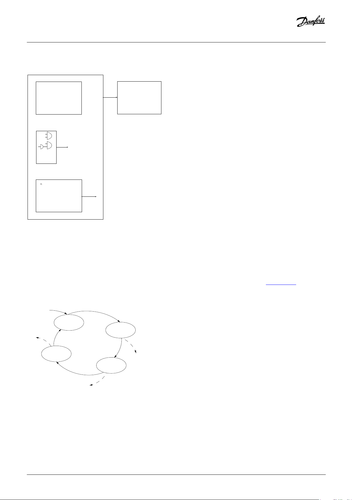
. . .
. . .
Par. 13-11
Comparator Operator
Par. 13-43
Logic Rule Operator 2
Par. 13-51
SL Controller Event
Par. 13-52
SL Controller Action
e30bb671.13
Coast
Start timer
Set Do X low
Select set-up 2
. . .
Running
Warning
Torque limit
Digital input X 30/2
. . .
=
TRUE longer than..
. . .
. . .
e30ba062.15
State 1
13-51.0
13-52.0
State 2
13-51.1
13-52.1
Start
event P13-01
State 3
13-51.2
13-52.2
State 4
13-51.3
13-52.3
Stop
event P13-02
Stop
event P13-02
Stop
event P13-02
Design Guide | VLT® AutomationDrive FC 301/302
Product Features
Illustration 37: Associated Action
Events and actions are each numbered and linked in pairs (states). This means that when event [0] is fulfilled (attains the value true),
action [0] is executed. After this, the conditions of event [1] are evaluated and if evaluated true, action [1] is executed, and so on. Only 1
event is evaluated at any time. If an event is evaluated as false, nothing happens (in the SLC) during the current scan interval, and no
other events are evaluated. When the SLC starts, it evaluates event [0] (and only event [0]) each scan interval. Only when event [0] is
evaluated true, the SLC executes action [0] and starts evaluating event [1]. It is possible to program 1–20 events and actions.
When the last event/action has been executed, the sequence starts over again from event [0]/action [0]. See illustration 38 for an
example with 3 events/actions:
Illustration 38: Sequence with 4 Events/Actions
Danfoss A/S © 2019.10
AJ286655760917en-000101 / 130R0301| 67
Page 68

Par. 13-11
Comparator Operator
=
TRUE longer than.
. . .
. . .
Par. 13-10
Comparator Operand
Par. 13-12
Comparator Value
e30bb672.10
. . .
. . .
. . .
. . .
Par. 13-43
Logic Rule Operator 2
Par. 13-41
Logic Rule Operator 1
Par. 13-40
Logic Rule Boolean 1
Par. 13-42
Logic Rule Boolean 2
Par. 13-44
Logic Rule Boolean 3
e30bb673.10
Design Guide | VLT® AutomationDrive FC 301/302
Product Features
6.2.12.1 Comparators
Comparators are used for comparing continuous variables (for example, output frequency, output current, and analog input) to fixed
preset values.
Illustration 39: Comparators
6.2.12.2 Logic Rules
Combine up to 3 boolean inputs (true/false inputs) from timers, comparators, digital inputs, status bits, and events using the logical
operators and, or, and not.
Illustration 40: Logic Rules
6.2.13 Safe Torque Off
To run STO, extra wiring for the drive is required. Refer to the VLT® Safe Torque Off Operating Guide for further information.
Liability conditions
The customer is responsible for ensuring that personnel know how to install and operate the Safe Torque Off function by:
• Reading and understanding the safety regulations concerning health, safety, and accident prevention.
• Understanding the generic and safety guidelines provided in the VLT® Safe Torque Off Operating Guide.
• Having a good knowledge of the generic and safety standards for the specific application.
6.3 Dynamic Braking Overview
Dynamic braking slows the motor using 1 of the following methods:
68 | Danfoss A/S © 2019.10
AJ286655760917en-000101 / 130R0301
Page 69

Design Guide | VLT® AutomationDrive FC 301/302
• AC brake:
- The brake energy is distributed in the motor by changing the loss conditions in the motor (parameter 2-10 Brake Function = [2]
AC Brake). The AC brake function cannot be used in applications with high cycling frequency since this situation overheats the
motor.
• DC brake:
- An overmodulated DC current added to the AC current works as an eddy current brake (parameter 2-02 DC Braking Time ≠ 0 s).
• Resistor brake:
- A brake IGBT keeps the overvoltage under a certain threshold by directing the brake energy from the motor to the connected
brake resistor (parameter 2-10 Brake Function = [1] Resistor Brake). For more information on selecting a brake resistor, see the
VLT® Brake Resistor MCE 101 Design Guide.
For drives equipped with the brake option, a brake IGBT along with terminals 81(R-) and 82(R+) are included for connecting an external
brake resistor. The function of the brake IGBT is to limit the voltage in the DC link whenever the maximum voltage limit is exceeded. It
limits the voltage by switching the externally mounted resistor across the DC bus to remove excess DC voltage present on the bus
capacitors.
External brake resistor placement has the advantages of selecting the resistor based on application need, dissipating the energy
outside of the control panel, and protecting the drive from overheating if the brake resistor is overloaded. The brake IGBT gate signal
originates on the control card and is delivered to the brake IGBT via the power card and gatedrive card. Also, the power and control
cards monitor the brake IGBT for a short circuit. The power card also monitors the brake resistor for overloads.
Product Features
External brake resistor placement has the advantages of selecting the resistor based on application need, dissipating the energy
outside of the control panel, and protecting the drive from overheating if the brake resistor is overloaded.
6.4 Mechanical Holding Brake Overview
Dynamic braking is established by:
• Brake resistor:
- A brake IGBT keeps the overvoltage under a certain threshold by directing the brake energy from the motor to the connected
brake resistor (parameter 2-10 Brake Function = [1] Resistor brake).
• AC brake
- The brake energy is distributed in the motor by charging the loss conditions in the motor. The AC brake function cannot be
used in applications with high cycling frequency since this overheats the motor (parameter 2-10 Brake Function = [2] AC brake).
• DC brake
- An overmodulated DC current added to the AC current works as an eddy current brake (parameter 2-02 DC Braking Time ≠ 0 s).
6.4.1 Open-loop Mechanical Brake Control
To control a mechanical brake, a relay output (relay 1 or relay 2) or a programmed digital output (terminal 27 or 29) is required.
Normally, this output must be closed during periods when the drive is unable to hold the motor, for example, due to an excessive load.
In parameter 5-40 Function Relay, 5-30 Terminal 27 Digital Output, or parameter 5-31 Terminal 29 Digital Output, select [32] Mechanical
Brake Control for applications with an electromechanic brake. When selecting [32] Mechanical Brake Control, the mechanical brake is
closed from start-up until the output current is above the level selected in parameter 2-20 Release Brake Current.
During stop, the mechanical brake activates when the speed drops below the level specified in parameter 2-21 Activate Brake Speed
[RPM]. If the drive enters an alarm condition, an overcurrent, or overvoltage situation, the mechanical brake immediately cuts in. This is
also the case during STO.
Danfoss A/S © 2019.10
AJ286655760917en-000101 / 130R0301| 69
Page 70

Start
term.18
1=on
0=off
Shaft speed
Start delay time
on
off
Brake delay time
Time
Output current
Relay 01
Pre-magnetizing
current or
DC hold current
Reaction time EMK brake
Par 2-20
Release brake current
Par 1-76 Start current/
Par 2-00 DC hold current
Par 1-74
Start speed
Par 2-21
Activate brake
speed
Mechanical brake
locked
Mechanical brake
free
Par 1-71
Par 2-23
e30ba074.13
Design Guide | VLT® AutomationDrive FC 301/302
Product Features
NOTICE
Protection mode and trip delay features (parameter 14-25 Trip Delay at Torque Limit and parameter 14-26 Trip Delay at Inverter
Fault) may delay the activation of the mechanical brake in an alarm condition.
Disable these functions in hoisting applications.
-
Illustration 41: Mechanical Brake
6.4.2 Closed-loop Mechanical Brake Control/Hoist Mechanical Brake
The hoist mechanical brake supports the following functions:
• 2 channels for mechanical brake feedback to offer further protection against unintended behavior resulting from a broken cable.
• Monitoring of mechanical brake feedback throughout the complete cycle. This helps protect the mechanical brake, especially if
• No ramp up until feedback confirms that the mechanical brake is open.
Improved load control at stop
If parameter 2-23 Activate Brake Delay is set too short, warning 22, Hoist Mech Brake is activated and the torque is not allowed to ramp
down.
• The transition when the motor takes over the load from the brake can be configured. Parameter 2-28 Gain Boost Factor can be
• Set parameter 2-28 Gain Boost Factor to 0 to enable position control during parameter 2-25 Brake Release Time. This enables
70 | Danfoss A/S © 2019.10
more drives are connected to the same shaft.
increased to minimize the movement. For smooth transition, change the setting from the speed control to the position control
during the change-over.
parameters 2-30 to 2-33, which are PID parameters for the position control.
AJ286655760917en-000101 / 130R0301
Page 71

e30ba642.12
A22
Active
W22
Active
W22
Active
A22
Active
High
Low
High
Low
Open
Closed
Delay
P. 2-23
Down Time
p. 2-29
P. 2-24
Ramp 1 Down
P. 3-42
Ramp 1 Up
P. 3-41Time
p. 2-25
Up Time
p. 2-27
Stop Delay
Activate Brake
Torque Ramp
Brake Release
Torque Ramp
Motor
speed
Torque
ref.
Brake
relay
Mech brake
feedback
Mech brake
position
Gain boost or
position control
Gain Boost p. 2-28
Contact no. 2
OPTIONAL
e.g. DI32 [70] Mech. Brake Feedback
Contact no. 1
e.g. DI32 [70] Mech. Brake Feedback
Torque ref. p. 2-26
Design Guide | VLT® AutomationDrive FC 301/302
Product Features
Illustration 42: Brake Release Sequence for Hoist Mechanical Brake Control
This brake control is available in flux with motor feedback only, available for asynchronous and non-salient PM motors.
Parameters 2-30 to 2-33 can be set up for smooth transition change from speed control to position control during parameter 2-25 Brake
Release Time. The brake release time is the time when the load is transferred from the mechanical brake to the drive.
Parameters 2-30 to 2-33 are activated when parameter 2-28 Gain Boost Factor is set to 0.
NOTICE
For an example of advanced mechanical brake control for hoisting applications, see the Applications Examples section.
-
6.5 Load Sharing Overview
Load sharing enables connection of multiple Danfoss VLT® drives over the same DC link with the following benefits:
Danfoss A/S © 2019.10
AJ286655760917en-000101 / 130R0301| 71
Page 72

Design Guide | VLT® AutomationDrive FC 301/302
• Energy savings:
- A motor running in regenerative mode can supply drives that are running in motoring mode. Alternatively, the motor running
in regenerative mode can supply any brake resistors used with the drives.
• Reduced need for spare parts:
- Usually, only 1 brake resistor is required for the installation instead of a brake resistor for each drive.
• Power back-up:
- If there was mains failure, all Danfoss VLT® drives can be supplied through the DC link from a back-up. The application can thus
continue running or go through a controlled shutdown process.
Product Features
6.5.1 Preconditions and Special Conditions
Before considering load sharing, ensure that the following preconditions are met:
• Equip the drives with load sharing terminals. Enclosure sizes A1–A5 and B3 have load sharing terminals by default.
• Enclosure sizes B, C, and F must be configured for load sharing when ordering. The standard load share selection in character 21 or
the type code is D, but other selections are available. For more configuration options, see Drivecat. It is not possible to retrofit load
sharing terminals on enclosure sizes B, C, and F.
• Enclosure sizes D and E must be configured for load sharing either when ordering or by using a retrofit kit. The standard load share
selection in character 21 of the type code is D, but other options are available. For more configuration options, see the Drivecat.
• The drives considered for load sharing must be of the same product series.
• The drives must all have the same voltage rating, for example, use T5 with T5 only.
• Place the drives physically close to each other to allow the wiring between to be as short as possible (maximum 25 m (82 ft)). Build
the wiring symmetrically around the drives with the highest power. Moreover, run the 2 wires closely together and, if possible,
twisted.
• When adding a brake resistor in a load sharing configuration, equip all drives with a brake chopper.
• A brake chopper is specified in the type code when ordering and cannot be retrofitted. The standard selection in character 18 of
the type code is B. For enclosure size A1, selection U, brake chopper + STO, is also a possibility.
NOTICE
Continuously monitor the Drive ready signal of the drives. The Drive ready signal impacts the overall application control.
NOTICE
MISSING PHASE AND OVERCURRENT PROTECTION REQURIED
Drives can have their rectifier overloaded even though the DC link does not show a high level of voltage ripple. Therefore, the
mains supply must be equipped with missing phase and overcurrent protection.
NOTICE
UNINTEDED WARNINGS OR REDUCED PERFORMANCE
In a load sharing application, the AC-brake function does not work as expected. The function checks for regenerative power,
but in a load sharing application, the regenerative power can come from another drive.
Turn off the AC-brake function in load sharing applications (parameter 2-10 Brake Function). Example: A drive without a
-
brake is combined with a drive with brake. When the drive with a brake is braked, the other drive receives an overcurrent
warning. Performance is not affected.
72 | Danfoss A/S © 2019.10
AJ286655760917en-000101 / 130R0301
Page 73

Design Guide | VLT® AutomationDrive FC 301/302
Product Features
NOTICE
The start-up time of the drive may be slightly longer than normal.
NOTICE
According to the EMC Directive, a system is defined as a combination of several types of equipment, finished products, and/or
components combined, designed and/or put together by the same person (system manufacturer) intended to be placed on the
market for distribution as a single functional unit for an end user and intended to be installed and operated together to
perform a specific task. The EMC directive applies to products/systems and installations, but in case the installation is built up of
CE marked products/systems the installation can also be considered compliant with the EMC directive. Installations shall not be
CE marked.
According to the EMC Directive, Danfoss Drives as a manufacturer of product/systems is responsible for obtaining the essential
requirements of the EMC directive and attaching the CE mark. For systems involving load sharing and other DC terminals,
Danfoss Drives can only ensure compliance to EMC Directive when end users connect combinations of Danfoss Drives products
as described in our technical documentation.
If any third-party products are connected to the load share or other DC terminals on the AC drives, Danfoss Drives cannot
guarantee that the EMC requirements are fulfilled.
6.5.2 Combinations of Enclosure Sizes
The concept for limiting inrush current in the DC-link capacitors is not the same for all enclosure sizes. Therefore, options for
combining different enclosure sizes in load sharing applications are limited.
NOTICE
RISK OF DRIVE FAILURE
Combining enclosure sizes that have different inrush control principles may lead to drive failure.
Ensure that the applied inrush control principles are compatible before combining drives in a load sharing application.
-
Table 12: Inrush Control Principles for Individual Enclosure Sizes
Enclosure size Principle
A DC inrush self-limited
B
C AC inrush thyristor limited
D AC inrush resistor limited
E
F
The following enclosure size combinations are possible in load sharing applications:
Danfoss A/S © 2019.10
AJ286655760917en-000101 / 130R0301| 73
Page 74

Design Guide | VLT® AutomationDrive FC 301/302
• A and B enclosures can be combined with other A or B enclosures.
• C, D, E, and F enclosures can be combined with other C, D, E, or F enclosures. However, C enclosures can only be combined with F
enclosures under the following circumstances:
- All drives are connected to mains or
- only the F enclosure is connected to mains.
• It is not possible to combine F and C enclosures if only the C enclosure is connected to mains.
• If the A/B enclosure drive is not connected to mains, A and B enclosures can be combined with C, D, E, or F enclosures.
Product Features
NOTICE
RISK OF DRIVE FAILURE
Combining A or B enclosures connected to mains with C, D, E, or F enclosures causes overload of the rectifier in the A and B
enclosures during inrush and normal load conditions.
Ensure that A and B enclosures are not connected to mains when combining them with C, D, E, or F enclosures.
-
To have the correct design of load sharing circuit, consult the application note Load Sharing for more details.
6.6 Regen Overview
Regen typically occurs in applications with continuous braking such as cranes/hoists, downhill conveyors, and centrifuges where
energy is pulled out of a decelerated motor.
• The load drives the motor when the drive is operated at a constant output frequency. This is referred to as an overhauling load.
• During deceleration, if the inertia of the load is high and the deceleration time of the drive is set to a short value.
As standard, the drive cannot regenerate energy back to the input. The drive can use the internal brake chopper, which allows the
excess energy to be dissipated in the form of heat within the external connected brake resistor.
Drives equipped with Active Front End (AFE) enables removal of excess energy using 1 of the following options:
• Brake chopper allows the excess energy to be dissipated in the form of heat within the brake resistor coils.
• Regen terminals allow a 3rd-party Regen to be connected to the drive, allowing the excess energy to be returned to the power
grid.
Returning excess energy back to the power grid is the most efficient use of regenerated energy in applications using continuous
braking.
74 | Danfoss A/S © 2019.10
AJ286655760917en-000101 / 130R0301
Page 75

Design Guide | VLT® AutomationDrive FC 301/302
Product Features
NOTICE
According to the EMC Directive, a system is defined as a combination of several types of equipment, finished products, and/or
components combined, designed and/or put together by the same person (system manufacturer) intended to be placed on the
market for distribution as a single functional unit for an end-user and intended to be installed and operated together to
perform a specific task. The EMC directive applies to products/systems and installations, but in case the installation is built up of
CE marked products/systems the installation can also be considered compliant with the EMC directive. Installations shall not be
CE marked.
According to the EMC Directive, Danfoss Drives as a manufacturer of product/systems is responsible for obtaining the essential
requirements of the EMC directive and attaching the CE mark. For systems involving load sharing and other DC terminals,
Danfoss Drives can only ensure compliance to EMC Directive when end-users connect combinations of Danfoss Drives products
as described in our technical documentation.
If any third-party products are connected to the load share or other DC terminals on the AC drives, Danfoss Drives cannot
guarantee that the EMC requirements are fulfilled.
Danfoss A/S © 2019.10
AJ286655760917en-000101 / 130R0301| 75
Page 76

4
3
2
1
e30bu325.10
Design Guide | VLT® AutomationDrive FC 301/302
Options and Accessories Overview
7 Options and Accessories Overview
7.1 Introduction
Danfoss offers an extensive range of options and accessories.
This chapter provides an overview of the different hardware options and accessories for the VLT® FC drive series:
• Fieldbus options
• Functional extensions
• Programmable controllers
• Power options
• Kits and accessories
7.2 VLT® FC Series Options Concept
Options are used to add extra features to the drive. That allows tailoring the drive to the specific need and application.
The drives have 4 option slots (A, B, C, and D).
1 A option
3 D option
Illustration 43: Option Slots on a VLT® FC Series Drive (Example Compact Enclosure)
The A-slot options are typically communication options, for example, for adding fieldbus functionality.
76 | Danfoss A/S © 2019.10
2 B option
4 C option
AJ286655760917en-000101 / 130R0301
Page 77

Design Guide | VLT® AutomationDrive FC 301/302
Options and Accessories Overview
The B-slot options typically host functional extension options.
The C-slot options host special function options, e.g for motion control.
The D-slot option is used for an external power supply.
The options are slot-specific. So an A-option does only fit in an A-option slot.
Some options are drive-specific, as they require an application-specific operating system in the drive.
Some additional functionalities are not implemented via hardware options, but via specific software options, for example IMC
(Integrated Motion Control), which is a software option included in a separate version of the operating system.
For a more detailed overview of available options, download the VLT® Drives FC Series Options Portfolio from www.danfoss.com.
7.3 VLT® Fieldbus Options
This topic gives an overview of currently available option cards related to fieldbus communication for the VLT® FC AC drive series. The
fieldbus solutions brochure can be downloaded from www.danfoss.com in the Options and Accessories section.
More detailed descriptions of the fieldbus option cards can be found in the Installation Guides, Programming Guides, and Operating
Guides for the individual options. These manuals can be downloaded from the Danfoss documentation download page for VLT®
AutomationDrive FC 301/FC 302.
Table 13: Fieldbus Options
Option name Slot FC 102 FC 103 FC 202 FC 301 FC 302
VLT® PROFIBUS DP MCA 101
VLT® DeviceNet MCA 104
VLT® CANopen MCA 105
VLT® AK-LonWorks MCA 107 for ADAP-Kool
®
VLT® LonWorks MCA 108
VLT® BACNet MCA 109
VLT® PROFIBUS Converter MCA 113 (VLT® 3000 to VLT® FC 302)
VLT® PROFIBUS Converter MCA 114 (VLT® 5000 to VLT® FC 302)
VLT® PROFINET MCA 120
VLT® EtherNet/IP MCA 121
VLT® Modbus TCP MCA 122
VLT® POWERLINK MCA 123
VLT® EtherCAT MCA 124
VLT® BACNet/IP MCA 125
A x x x x x
A x – x x x
A – – – x x
A – x – – –
A x – – – –
A x x – – –
A – – – – x
A – – – – x
A x x x x x
A x – x x x
A x – x x x
A – – – x x
A – – – x x
A x – – – –
VLT® DeviceNet Converter MCA 194
Danfoss A/S © 2019.10
A – – – – x
AJ286655760917en-000101 / 130R0301| 77
Page 78

Design Guide | VLT® AutomationDrive FC 301/302
Options and Accessories Overview
7.4 VLT® Functional Extensions
This topic gives an overview of currently available option cards for functional extension.
More detailed descriptions of the functional extension option cards can be found in the Installation Guides, Programming Guides, and
Operating Guides for the individual options. These manuals can be downloaded from www.danfoss.com in the VLT®
AutomationDrive FC 301/FC 302 section.
Table 14: Functional Extensions
Option name Slot FC 102 FC 103 FC 202 FC 301 FC 302
VLT® General Purpose I/O Option MCB 101
VLT® Encoder Option MCB 102
VLT® Resolver Input MCB 103
VLT® Relay Card MCB 105
VLT® 24 V DC Supply Option MCB 107
VLT® Safe PLC Interface Option MCB 108
VLT® Analog I/O MCB 109 (incl. RTC backup)
VLT® PTC Thermistor Card MCB 112
VLT® Extended Relay Card MCB 113
VLT® Sensor Input MCB 114
VLT® Programmable I/O MCB 115
VLT® Real-time Clock MCB 117
VLT® Safety Option MCB 150 (TTL)
VLT® Safety Option MCB 151 (HTL)
VLT® Safety Option MCB 152 (PROFIsafe)
VLT® Sensorless Safety MCB 159
(1)
B x x x x x
B – – – x x
B – – – x x
B x x x x x
D x x x – x
B – – – – x
B x x x – –
B x – x x x
C – – – – x
B x – x x x
B – – – x x
D x x x x x
B – – – – x
B – – – – x
B – – – – x
– – – – – x
1
MCB 159 is factory-mounted and must be ordered with VLT® Safety Option MCB 151.
7.5 VLT® Programmable Controllers
Table 15: VLT® Programmable Controllers
Option name FC 102 FC 103 FC 202 FC 301 FC 302
VLT® Extended Cascade Controller MCO 101
VLT®Advanced Cascade Controller MCO 102
VLT®Motion Control Option MCO 305
VLT®Synchronizing Controller MCO 350
VLT®Position Controller MCO 351
78 | Danfoss A/S © 2019.10
B – – x – –
C – – x – –
C – – – x x
C – – – – x
C – – – – x
AJ286655760917en-000101 / 130R0301
Page 79

Design Guide | VLT® AutomationDrive FC 301/302
Option name FC 102 FC 103 FC 202 FC 301 FC 302
Integrated Motion Controller IMC S067 (software option) – – – – – x
Options and Accessories Overview
7.6 VLT® Power Options
7.6.1 VLT® Harmonic Filters
Table 16: VLT® Harmonic Filters
Option name FC 102 FC 103 FC 202 FC 301 FC 302
VLT® Advanced Harmonic Filter AHF 005
VLT® Advanced Harmonic Filter AHF 010
The VLT® Advanced Harmonic Filters AHF 005 & AHF 010 are not comparable with traditional harmonic trap filters. The Danfoss VLT®
harmonic filters have been specially designed to match the Danfoss VLT® drives.
By connecting the AHF 005 or AHF 010 in front of a Danfoss VLT® drive, the total harmonic current distortion generated back to the
mains is reduced to 5% (AHF 005) and 10% (AHF 010).
For order numbers and more information on harmonic mitigation, refer to 10.18 Harmonics Overview, 12.2.11 Ordering of Harmonic
Filters, and for more detailed information the VLT® Advanced Harmonic Filters AHF 005/AHF 010 Design Guide.
x x x x x
x x x x x
7.6.2 VLT® Sine-wave Filters
Table 17: VLT® Sine-wave Filters
Option name FC 102 FC 103 FC 202 FC 301 FC 302
VLT® Sine-wave Filter MCC 101
When a drive controls a motor, resonance noise is heard from the motor. This noise, which is the result of the motor design, occurs
every time an inverter switch in the drive is activated. The frequency of the resonance noise thus corresponds to the switching
frequency of the drive.
x x x x x
Danfoss supplies a sine-wave filter to dampen the acoustic motor noise. The filter reduces the ramp-up time of the voltage, the peak
load voltage (U
acoustic motor noise is reduced to a minimum.
The ripple current in the sine-wave filter coils also causes some noise. Solve the problem by integrating the filter in a cabinet or
enclosure.
For order numbers and more information on how to dimension sine-wave filters, refer to
Filters MCC 101, and for more detailed information the VLT® FC Series Output Filter Design Guide.
Danfoss A/S © 2019.10
), and the ripple current (ΔI) to the motor, which means that current and voltage become almost sinusoidal. The
PEAK
12.2.12 Order Numbers for VLT® Sine-wave
AJ286655760917en-000101 / 130R0301| 79
Page 80

Design Guide | VLT® AutomationDrive FC 301/302
Options and Accessories Overview
7.6.3 VLT® dU/dt Filters
Table 18: VLT® dU/dt Filters
Option name FC 102 FC 103 FC 202 FC 301 FC 302
VLT® Sine-wave Filter MCC 102
Danfoss supplies dU/dt filters. dU/dt filters are differential mode, low-pass filters that reduce motor terminal phase-to-phase peak
voltages and reduce the rise time to a level that lowers the stress on the insulation at the motor windings. This is especially an issue
with short motor cables.
Compared to the sine-wave filters, the dU/dt filters have a cut-off frequency above the switching frequency.
For order numbers and more information on how to dimension dU/dt filters, refer to 10.15 dU/dt Conditions, 12.2.13 Order Numbers
for VLT® dU/dt Filters MCC 102, and for more detailed information the VLT® FC Series Output Filter Design Guide.
x x x x x
7.6.4 VLT® Common-mode Filters
Table 19: VLT® Common Mode Filters
Option name FC 102 FC 103 FC 202 FC 301 FC 302
VLT® Common Mode Filter MCC 105
High-frequency common-mode cores (HF-CM cores) reduce electromagnetic interference and eliminate bearing damage by electrical
discharge. They are special nanocrystalline magnetic cores that have superior filtering performance compared to regular ferrite cores.
The HF-CM core acts like a common-mode inductor between phases and ground.
Installed around the 3 motor phases (U, V, W), the common-mode filters reduce high-frequency common-mode currents. As a result,
high-frequency electromagnetic interference from the motor cable is reduced.
x x x x x
For ordering numbers, refer to the
VLT® FC Series Output Filter Design Guide.
7.6.5 VLT® Brake Resistors
Table 20: VLT® Brake Resistors
Option name FC 102 FC 103 FC 202 FC 301 FC 302
VLT® Brake Resistor MCE 101
In applications where the motor is used as a brake, energy is generated in the motor and sent back into the drive. If the energy cannot
be transported back to the motor, it increases the voltage in the drive DC line. In applications with frequent braking and/or high inertia
loads, this increase can lead to an overvoltage trip in the drive and, finally, a shutdown.
Brake resistors are used to dissipate the excess energy resulting from the regenerative braking.
The resistor is released based on its ohmic value, its power dissipation rate, and its physical size. Danfoss offers a wide variety of
different resistors that are specially designed for Danfoss drives.
For basic information on brake resistor selection, see 10.10.1 Selection of Brake Resistor.
x – x x x
80 | Danfoss A/S © 2019.10
AJ286655760917en-000101 / 130R0301
Page 81

1 2
e30bu327.10
A B
C
Design Guide | VLT® AutomationDrive FC 301/302
For order numbers and more information on how to dimension brake resistors, refer to 12.2.9 Ordering of VLT® Brake Resistors MCE
101, and for more detailed information the VLT® Brake Resistor MCE 101 Design Guide.
Options and Accessories Overview
7.6.6 VLT® Line Reactors
Table 21: VLT® Line Reactors
Option name FC 102 FC 103 FC 202 FC 301 FC 302
VLT® Line Reactor MCC 103
See 10.18.7 Line Reactors for details on using line reactors in load sharing applications.
x – x x x
7.7 Kits and Accessories
7.7.1 Panel Through Mounting Kits for VLT® FC Series Enclosure Sizes A, B, and C
The panel through mounting kit can be used for cooling the heat sink via an external air stream, or where there is a wish to use a
separate air duct. The electronics are sealed from the external air by use of the mounting flange and sealing gasket. This way the
electronics are hosued within the control panel, while the heat sink protrudes through the panel.
There are specific kits available for enclosure sizes A5, B1, B2, C1, C2. See 12.2.6 Order Numbers for Miscellaneous Hardware.
The backplate (must be purchased separately) is used if an air duct is not available. Mounted in a duct construction, the built-in fan can
be removed and the cooling air provided by an external fan.
A Drive mounted with a panel through mounting kit.
C Panel through kit without backplate for installation in air
duct.
Danfoss A/S © 2019.10
B Panel through kit with backplate for use with internal fan.
1 Mounting flange with sealing gasket.
AJ286655760917en-000101 / 130R0301| 81
Page 82

A
B
C
D
E
e30bt323.10
Design Guide | VLT® AutomationDrive FC 301/302
Options and Accessories Overview
2 Backplate.
Illustration 44: Panel Though Mounting Kit on VLT® AutomationDrive FC 302
7.7.2 IP21/NEMA Type 1 Enclosure Kits for VLT® FC Series Enclosure Sizes A, B, and C
IP20/IP4X top/Nema Type 1 is an optional enclosure element available for IP20 compact units. If the enclosure kit is used, an IP20 unit is
upgraded to comply with enclosure IP21/4X top/Nema Type 1. The IP4X top can be applied to all standard IP20 enclosure variants.
82 | Danfoss A/S © 2019.10
AJ286655760917en-000101 / 130R0301
Page 83

B
A
E
C
D
e30bt324.10
Design Guide | VLT® AutomationDrive FC 301/302
Options and Accessories Overview
A Top cover
C Base part
B Brim
D Base cover
E Screw(s)
Illustration 45: IP21/Nema Type 1 Kit on A2 Enclosure and A3 Enclosure
Place the top cover as shown. If an A or B option is used, fit the brim to cover the top inlet. Place the base part C at the bottom of the
drive and use the clamps from the accessory bag to correctly fasten the cables.
Holes for cable glands:
• Enclosure size A2: 2x M25 and 3xM32.
• Enclosure size A3: 3xM25 and 3xM32.
Danfoss A/S © 2019.10
AJ286655760917en-000101 / 130R0301| 83
Page 84

E
F
D
C
B
A
e30bt620.12
Design Guide | VLT® AutomationDrive FC 301/302
Options and Accessories Overview
A Top cover
C Base part
E Screw(s)
B Brim
D Base cover
F Fan cover
84 | Danfoss A/S © 2019.10
AJ286655760917en-000101 / 130R0301
Page 85

e30bt621.12
D
C
A
G
Design Guide | VLT® AutomationDrive FC 301/302
Options and Accessories Overview
A Top cover
D Base cover
Illustration 46: IP21/Nema Type 1 Kit on B3 Enclosure (Upper) and B4/C3/C4 Enclosure (Lower)
When option module A and/or option module B is/are used, fit the brim (B) to the top cover (A).
Danfoss A/S © 2019.10
C Base part
G Top clip
AJ286655760917en-000101 / 130R0301| 85
Page 86

Design Guide | VLT® AutomationDrive FC 301/302
NOTICE
Side-by-side installation is not possible when using the IP21/IP4X/Nema Type 1 Enclosure Kit.
Table 22: Enclosure Dimensions with installed IP21/Nema Type 1 Kit
Options and Accessories Overview
Enclosure size Height A [mm (in)] Width B [mm (in)]
Depth C
(1)
[mm (in)]
A2 372 (14.6) 90 (3.5) 205 (8.1)
A3 372 (14.6) 130 (5.1) 205 (8.1)
B3 475 (18.7) 165 (6.5) 249 (9.8)
B4 670 (26.4) 255 (10.1) 246 (9.7)
C3 755 (29.7) 329 (13.0) 337 (13.3)
C4 950 (37.4) 391 (15.4) 337 (13.3)
1
If an A and/or B option is used, the depth increases.
7.7.3 Mounting Brackets for VLT® FC Series Enclosure Sizes A5, B1, B2, C1, and C2
The kits contain an upper and a lower bracket for the respective enclosure size.
Table 23: Mounting Brackets, Dimensions
Enclosure size Protection Rating A [mm (in)] B [mm (in)]
A5 IP55/66 480 (18.9) 495 (19.5)
B1 IP21/55/66 535 (21.1) 550 (21.7)
B2 IP21/55/66 705 (27.8) 720 (28.4)
C1 IP21/55/66 730 (28.7) 745 (29.3)
C2 IP21/55/66 820 (32.3) 835 (32.9)
86 | Danfoss A/S © 2019.10
AJ286655760917en-000101 / 130R0301
Page 87

e30ba845.10
A
B
Design Guide | VLT® AutomationDrive FC 301/302
Options and Accessories Overview
Danfoss A/S © 2019.10
AJ286655760917en-000101 / 130R0301| 87
Page 88

e30ba847.10
Design Guide | VLT® AutomationDrive FC 301/302
Options and Accessories Overview
Illustration 47: Mounting Brackets for VLT® FC Series Enclosure Sizes A5, B1, B2, C2 and C2
7.7.4 Remote Mounting Kits for LCP
3 different remote mounting kits are available for the VLT® FC Series:
• Remote mounting kit for LCP with cover for outdoor mounting.
• Remote mounting kit with graphical LCP.
• Remote mounting kit with numerical LCP.
7.7.4.1 Remote Mounting Kit for LCP 102 and LCP 103 with Cover for Outdoor Mounting
The kit allows the LCP to be mounted apart from the drive, for example, in a wall or panel. The LCP mounting kit provides the following
features:
88 | Danfoss A/S © 2019.10
AJ286655760917en-000101 / 130R0301
Page 89

e30bf910.10
Design Guide | VLT® AutomationDrive FC 301/302
• Simple mounting, only one 24 mm bore required for mounting.
• IP54 protection rating of the LCP mounting.
• Protecting LCP from direct sunlight.
• Possibility to lock the LCP cover to prevent unauthorized access.
• LCP cover locking in an open position, for example, for commissioning.
• Indicators for alarms and warnings are visible through the cover.
• Can be mounted on a wall from 0.1–90 mm thickness.
The kit contains the following parts (see 12.2.7 Order Numbers for Local Control Panel Options):
• LCP cables with 2 M12 connectors (90° male connector and straight female connector).
• Cable to the LCP.
• Blind cover with M12 female connector.
• Base plate with D-sub connector and M12 male connector.
• Two gaskets and 1 nut for the D-sub connector.
• Intermediate cover with the front cover.
• Disassembly tool.
Options and Accessories Overview
Illustration 48: Remote Connection of the LCP
7.7.4.2 Panel Mounting Kit for LCP 102, LCP 101, and LCP 103
The kit allows the LCP to move the LCP to the front of a cabinet.
Danfoss A/S © 2019.10
AJ286655760917en-000101 / 130R0301| 89
Page 90

130BA138.11
e30ba200.10
Design Guide | VLT® AutomationDrive FC 301/302
The kit contains the following parts:
• Optional: Graphical LCP 102, numerical LCP 101, or Wireless Control Panel LCP 103.
• 3 m (10 ft) cable to the LCP.
• Gasket.
• Fasteners.
Options and Accessories Overview
For order number, see:
12.2.7 Order Numbers for Local Control Panel Options.
Illustration 49: Panel Mounting Kit for LCP 102, LCP 101, and LCP 103
90 | Danfoss A/S © 2019.10
AJ286655760917en-000101 / 130R0301
Page 91

Max R2(0.08)
Panel
cut out
Min 72(2.8)
e30ba139.11
129.5± 0.5 mm
64.5± 0.5 mm
(2.54± 0.04 in)
(5.1± 0.04 in)
e30bg047.10
Design Guide | VLT® AutomationDrive FC 301/302
Illustration 50: Panel Mounting Kit Dimensions
Options and Accessories Overview
7.7.5 VLT® Wireless Communication Panel LCP 103 and MyDrive® Connect
The VLT® Wireless Communication Panel LCP 103 communicates with MyDrive® Connect – an app which can be downloaded to iOSand Android-based smart devices.
MyDrive® Connect offers full access to the drive making it easier to perform commissioning, operation, monitoring and maintenance
tasks. Utilizing the active point-to-point wireless connection, maintenance personnel can receive real-time error messages via the app
to ensure a quick response to potential issues and reduce downtime.
®
Illustration 51: VLT
Wireless Communication Panel LCP 103
Danfoss A/S © 2019.10
AJ286655760917en-000101 / 130R0301| 91
Page 92

Design Guide | VLT® AutomationDrive FC 301/302
Specifications
8 Specifications
8.1 Enclosure Size by Power Rating
The VLT® AutomationDrive FC 301/FC 302 is available in several enclosure sizes depending on the power size and enclosure rating
protection.
Table 24: Enclosure Power Ratings, 200–240 V AC
kW
(1)
hp Available enclosure sizes
IP20/Chassis IP21/Type 1 IP55/Type 12 IP66/Type 4X
0.25 0.34 A1/A2 A1/A2 A4/A5 A4/A5
0.37 0.50 A1/A2 A1/A2 A4/A5 A4/A5
0.55 0.75 A1/A2 A1/A2 A4/A5 A4/A5
0.75 1.0 A1/A2 A1/A2 A4/A5 A4/A5
1.1 1.5 A1/A2 A1/A2 A4/A5 A4/A5
1.5 2.0 A1/A2 A1/A2 A4/A5 A4/A5
2.2 3.0 A2 A2 A4/A5 A4/A5
3.0 4.0 A3 A3 A5 A5
3.7 5.0 A3 A3 A5 A5
5.5 7.5 B3 B1 B1 B1
7.5 10 B3 B1 B1 B1
11 15 B4 B2 B2 B2
15 20 B4 C1 C1 C1
18 25 C3 C1 C1 C1
22 30 C3 C1 C1 C1
30 40 C4 C2 C2 C2
37 50 C4 C2 C2 C2
1
All power ratings are taken at high overload.
Table 25: Enclosure Power Ratings, 380–480 V AC
kW
(1)
hp Available enclosure sizes
IP20/Chassis IP21/Type 1 IP55/Type 12 IP66/Type 4X
0.37 0.50 A1/A2 A1/A2 A4/A5 A4/A5
0.55 0.75 A1/A2 A1/A2 A4/A5 A4/A5
0.75 1.0 A1/A2 A1/A2 A4/A5 A4/A5
1.1 1.5 A1/A2 A1/A2 A4/A5 A4/A5
1.5 2.0 A1/A2 A1/A2 A4/A5 A4/A5
2.2 3.0 A2 A2 A4/A5 A4/A5
3.0 4.0 A2 A2 A4/A5 A4/A5
92 | Danfoss A/S © 2019.10
AJ286655760917en-000101 / 130R0301
Page 93

Design Guide | VLT® AutomationDrive FC 301/302
Specifications
kW
(1)
hp Available enclosure sizes
4.0 5.0 A2 A2 A4/A5 A4/A5
5.5 7.5 A3 A3 A5 A5
7.5 10 A3 A3 A5 A5
11 15 B3 B1 B1 B1
15 20 B3 B1 B1 B1
18 25 B4 B2 B2 B2
22 30 B4 B2 B2 B2
30 40 B4 C1 C1 C1
37 50 C3 C1 C1 C1
45 60 C3 C1 C1 C1
55 75 C4 C2 C2 C2
75 100 C4 C2 C2 C2
1
All power ratings are taken at high overload.
Table 26: Enclosure Power Ratings, 525–600 V AC
kW
(1)
hp Available enclosure sizes
IP20/Chassis IP21/Type 1 IP55/Type 12 IP66/Type 4X
0.75 1.0 A3 A3 A5 A5
1.1 1.5 A3 A3 A5 A5
1.5 2.0 A3 A3 A5 A5
2.2 3.0 A3 A3 A5 A5
3.0 4.0 A3 A3 A5 A5
4.0 5.0 A3 A3 A5 A5
5.5 7.5 A3 A3 A5 A5
7.5 10 A3 A3 A5 A5
11 15 B3 B1 B1 B1
15 20 B3 B1 B1 B1
18 25 B4 B2 B2 B2
22 30 B4 B2 B2 B2
30 40 B4 C1 C1 C1
37 50 C3 C1 C1 C1
45 60 C3 C1 C1 C1
55 75 C4 C2 C2 C2
75 100 C4 C2 C2 C2
1
All power ratings are taken at high overload.
Danfoss A/S © 2019.10
AJ286655760917en-000101 / 130R0301| 93
Page 94

Design Guide | VLT® AutomationDrive FC 301/302
Table 27: Enclosure Power Ratings, 525–690 V AC
kW hp Available enclosure sizes
IP20/Chassis IP21/Type 1 IP55/Type 12 IP66/Type 4X
1.1 1.5 A3 -/A3 – –
1.5 2.0 A3 -/A3 – –
2.2 3.0 A3 -/A3 – –
3.0 4.0 A3 -/A3 – –
4.0 5.0 A3 -/A3 – –
5.5 7.5 A3 -/A3 – –
7.5 10 A3 -/A3 – –
11 15 B4 B2/B4 B2 –
15 20 B4 B2/B4 B2 –
18 25 B4 B2/B4 B2 –
22 30 B4 B2/B4 B2 –
30 40 B4 B4/C2 C2 –
37 50 C3 C2/C3 C2 –
45 60 C3 C2/C3 C2 –
55 75 D3h C2/D1h C2/D1h –
75 100 D3h C2/D1h C2/D1h –
Specifications
8.2 Electrical Data
8.2.1 Mains Supply 3x200–240 V AC, T2
Table 28: Mains Supply 3x200–240 V AC, High Overload, 0.25–3.0 kW
Type code PK25 PK37 PK55 PK75 P1K1 P1K5 P2K2 P3K0
Intermittent overload classification 160% (0.25–11kW), 150% (15–37 kW) for 1 minute/10 minutes
Typical shaft output power [kW @208V] 0.25 0.37 0.55 0.75 1.10 1.50 2.20 3.00
Typical shaft output power [hp @230V] 0.34 0.50 0.75 1.00 1.50 2.00 3.00 4.00
Protection rating IEC/UL [enclosure size]
IP20/Chassis
IP21/Type 1
IP55/Type 12
IP66/Type 4X
(1)
(1)
(2)
(2)
Rated output current
Continuous (200–240 V) [A] 1.80 2.40 3.50 4.60 6.6 7.5 10.6 12.5
A1/A2 A1/A2 A1/A2 A1/A2 A1/A2 A1/A2 A2 A3
A1/A2 A1/A2 A1/A2 A1/A2 A1/A2 A1/A2 A2 A3
A4/A5 A4/A5 A4/A5 A4/A5 A4/A5 A4/A5 A4/A5 A5
A4/A5 A4/A5 A4/A5 A4/A5 A4/A5 A4/A5 A4/A5 A5
94 | Danfoss A/S © 2019.10
AJ286655760917en-000101 / 130R0301
Page 95

Design Guide | VLT® AutomationDrive FC 301/302
Specifications
Type code PK25 PK37 PK55 PK75 P1K1 P1K5 P2K2 P3K0
Intermittent overload (200–240 V) [A] 2.9 3.8 5.6 7.4 10.6 12 17 20
Continuous apparent power (@208 V) [kVA] 0.65 0.86 1.26 1.66 2.38 2.7 3.82 4.5
Continuous apparent power (@230 V) [kVA] 0.72 0.96 1.39 1.83 2.63 2.99 4.22 4.98
Maximum input current
Continuous (200–240 V) [A] 1.6 2.2 3.2 4.1 5.9 6.8 9.5 11.3
Intermittent overload (200–240 V) [A] 2.56 3.52 5.12 6.56 9.44 10.88 15.2 18.08
More specifications
Power loss at rated maximum load estimated
Efficiency at rated output current
1
Enclosure size A1 is only available as FC 301.
2
Enclosure size A4 is only available without C and D options, or without C option but with backplate.
3
Applies to dimensioning of drive cooling. If the switching frequency is higher than the default setting, the power losses may increase. LCP and typical control card power consump-
tion is included. For power loss data according to IEC 61800-9-2, and EN 50598-2, refer to
4
For energy efficiency class, see 8.5 Ambient Conditions. For part load losses, see http.//ecosmart.danfoss.com/.
(4)
(3)
[W]
21 29 42 54 63 82 116 155
0.94 0.94 0.95 0.95 0.96 0.96 0.96 0.96
http://ecosmart.danfoss.com/
Table 29: Mains Supply 3x200–240 V AC, High Overload, 3.7–37 kW
Type code P3K7 P5K5 P7K5 P11K P15K P18K P22K P30K P37K
Intermittent overload classification 160% (0.25–11kW), 150% (15–37 kW) for 1 minute/10 minutes
Typical shaft output power [kW @208V] 3.70 5.50 7.5 11 15 18.5 22 30 37
Typical shaft output power [hp @230V] 5.00 7.50 10 15 20 25 30 40 50
Protection rating IEC/UL [enclosure size]
IP20/Chassis
IP21/Type 1
IP55/Type 12
IP66/Type 4X
(1)
(1)
(2)
(2)
A3 B3 B3 B4 B4 C3 C3 C4 C4
A3 B1 B1 B2 C1 C1 C1 C2 C2
A5 B1 B1 B2 C1 C1 C1 C2 C2
A5 B1 B1 B2 C1 C1 C1 C2 C2
Rated output current
Continuous (200–240 V) [A] 16.7 24.2 30.8 46.2 59.4 74.8 88 115 143
Intermittent overload (200–240 V) [A] 26.7 38.7 49.3 73.9 89.1 112 132 173 215
Continuous apparent power (@208 V) [kVA] 6.0 8.7 11.1 16.6 21.4 26.9 31.7 41.4 51.5
Continuous apparent power (@230 V) [kVA] 6.65 9.6 12.3 18.4 23.7 29.8 35.1 45.8 57
Maximum input current
Continuous (200–240 V) [A] 15 22 28 42 54 68 80 104 130
Intermittent overload (200–240 V) [A] 24 35.2 44.8 67.2 81 102 120 156 195
More specifications
Power loss at rated maximum load estimated
Danfoss A/S © 2019.10
(3)
185 239 371 463 624 740 874 1143 1400
[W]
AJ286655760917en-000101 / 130R0301| 95
Page 96

Design Guide | VLT® AutomationDrive FC 301/302
Specifications
Type code P3K7 P5K5 P7K5 P11K P15K P18K P22K P30K P37K
Efficiency at rated output current
1
Enclosure size A1 is only available as FC 301.
2
Enclosure size A4 is only available without C and D options, or without C option but with backplate.
3
Applies to dimensioning of drive cooling. If the switching frequency is higher than the default setting, the power losses may increase. LCP and typical control card power consump-
tion is included. For power loss data according to IEC 61800-9-2, and EN 50598-2, refer to
4
For energy efficiency class, see 8.5 Ambient Conditions. For part load losses, see http://ecosmart.danfoss.com/.
(4)
Table 30: Mains Supply 3x200–240 V AC, Normal Overload, 0.25–3.0 kW
0.96 0.96 0.96 0.96 0.96 0.97 0.97 0.97 0.97
http://ecosmart.danfoss.com/
Type code PK25 PK37 PK55 PK75 P1K1 P1K5 P2K2 P3K0
Intermittent overload classification 110% for 1 minute/10 minutes
Typical shaft output power [kW @208V] 0.25 0.37 0.55 0.75 1.10 1.50 2.20 3.00
Typical shaft output power [hp @230V] 0.34 0.50 0.75 1.00 1.50 2.00 3.00 4.00
Protection rating IEC/UL [enclosure size]
IP20/Chassis
IP21/Type 1
IP55/Type 12
IP66/Type 4X
(1)
(1)
(2)
(2)
A1/A2 A1/A2 A1/A2 A1/A2 A1/A2 A1/A2 A2 A3
A1/A2 A1/A2 A1/A2 A1/A2 A1/A2 A1/A2 A2 A3
A4/A5 A4/A5 A4/A5 A4/A5 A4/A5 A4/A5 A4/A5 A5
A4/A5 A4/A5 A4/A5 A4/A5 A4/A5 A4/A5 A4/A5 A5
Rated output current
Continuous (200–240 V) [A] 1.8 2.4 3.5 4.6 6.6 7.5 10.6 12.5
Intermittent overload (200–240 V) [A] 2.0 2.6 3.9 5.1 7.3 8.3 11.7 13.8
Continuous apparent power (@208 V) [kVA] 0.65 0.86 1.26 1.66 2.38 2.7 3.82 4.5
Continuous apparent power (@230 V) [kVA] 0.72 0.96 1.39 1.83 2.63 2.99 4.22 4.98
Maximum input current
Continuous (200–240 V) [A] 1.6 2.2 3.2 4.1 5.9 6.8 9.5 11.3
Intermittent overload (200–240 V) [A] 1.8 2.4 3.5 4.5 6.5 7.5 10.5 12.4
More specifications
Power loss at rated maximum load estimated
Efficiency at rated output current
1
Enclosure size A1 is only available as FC 301.
2
Enclosure size A4 is only available without C and D options, or without C option but with backplate.
3
Applies to dimensioning of drive cooling. If the switching frequency is higher than the default setting, the power losses may increase. LCP and typical control card power consump-
tion is included. For power loss data according to IEC 61800-9-2, and EN 50598-2, refer to http://ecosmart.danfoss.com/
4
For energy efficiency class, see 8.5 Ambient Conditions. For part load losses, see http://ecosmart.danfoss.com/.
(4)
(3)
[W]
21 29 42 54 63 82 116 155
0.94 0.94 0.95 0.95 0.96 0.96 0.96 0.96
96 | Danfoss A/S © 2019.10
AJ286655760917en-000101 / 130R0301
Page 97

Design Guide | VLT® AutomationDrive FC 301/302
Table 31: Mains Supply 3x200–240 V AC, Normal Overload, 3.7–37 kW
Specifications
Type code P3K7 P5K5 P7K5 P11K P15K P18K P22K P30K P37K
Intermittent overload classification 110% for 1 minute/10 minutes
Typical shaft output power [kW @208V] 3.70 5.50 7.5 11 15 18.5 22 30 37
Typical shaft output power [hp @230V] 5.00 7.50 10 15 20 25 30 40 50
Protection rating IEC/UL [enclosure size]
IP20/Chassis
IP21/Type 1
IP55/Type 12
IP66/Type 4X
(1)
(1)
(2)
(2)
A3 B3 B3 B4 B4 C3 C3 C4 C4
A3 B1 B1 B2 C1 C1 C1 C2 C2
A5 B1 B1 B2 C1 C1 C1 C2 C2
A5 B1 B1 B2 C1 C1 C1 C2 C2
Rated output current
Continuous (200–240 V) [A] 16.7 30.8 46.2 59.4 74.8 88 115 143 170
Intermittent overload (200–240 V) [A] 18.4 33.9 50.8 65.3 82.3 36.8 127 157 187
Continuous apparent power (@208 V) [kVA] 6.0 11.1 16.6 21.4 26.9 31.7 41.4 51.5 61.2
Continuous apparent power (@230 V) [kVA] 6.65 3.6 12.3 18.4 23.7 29.8 35.1 45.8 57
Maximum input current
Continuous (200–240 V) [A] 15 28 42 54 68 80 104 130 154
Intermittent overload (200–240 V) [A] 16.5 30.8 46.2 59.4 74.8 88 114 143 169
More specifications
Power loss at rated maximum load estimated
Efficiency at rated output current
1
Enclosure size A1 is only available as FC 301.
2
Enclosure size A4 is only available without C and D options, or without C option but with backplate.
3
Applies to dimensioning of drive cooling. If the switching frequency is higher than the default setting, the power losses may increase. LCP and typical control card power consump-
tion is included. For power loss data according to IEC 61800-9-2, and EN 50598-2, refer to
4
For energy efficiency class, see 8.5 Ambient Conditions. For part load losses, see http://ecosmart.danfoss.com/.
(4)
(3)
185 310 514 602 737 845 1140 1353 1636
[W]
0.96 0.96 0.96 0.96 0.96 0.97 0.97 0.97 0.97
http://ecosmart.danfoss.com/
8.2.2 Mains Supply 3x380–480 V AC, FC 301 T4 and 3x380–500 V AC, FC 302 T5
Table 32: Mains Supply 3x380–480 V AC (FC 301 T4) and 3x380–500 V AC (FC 302 T5), High Overload, 0.37–7.5 kW
Type code PK37 PK55 PK75 P1K1 P1K5 P2K2 P3K0 P4K0 P5K5 P7K5
Intermittent overload classification 160% (0.37–22 kW), 150% (30–75 kW) for 1 minute/10 minutes
Typical shaft output power [kW
@400 V]
Typical shaft output power [hp
@460 V]
Protection rating IEC/UL [enclosure size]
Danfoss A/S © 2019.10
0.37 0.55 0.75 1.1 1.5 2.2 3.0 4.0 5.5 7.5
0.5 0.75 1.0 1.5 2.0 3.0 4.0 5.0 7.5 10
AJ286655760917en-000101 / 130R0301| 97
Page 98

Design Guide | VLT® AutomationDrive FC 301/302
Specifications
Type code PK37 PK55 PK75 P1K1 P1K5 P2K2 P3K0 P4K0 P5K5 P7K5
IP20/Chassis
IP21/Type 1
IP55/Type 12
IP66/Type 4X
(1)
(1)
(2)
(2)
A1/A2 A1/A2 A1/A2 A1/A2 A1/A2 A2 A2 A2 A3 A3
A1/A2 A1/A2 A1/A2 A1/A2 A1/A2 A2 A2 A2 A3 A3
A4/A5 A4/A5 A4/A5 A4/A5 A4/A5 A4/A5 A4/A5 A4/A5 A5 A5
A4/A5 A4/A5 A4/A5 A4/A5 A4/A5 A4/A5 A4/A5 A4/A5 A5 A5
Rated output current
Continuous (380–440 V) [A] 1.3 1.8 2.4 3.0 4.1 5.6 7.2 10 13 16
Intermittent overload (380–440 V) [A] 2.1 2.9 3.8 4.8 6.6 9.0 11.5 16 20.8 25.6
Continuous (441–500 V) [A] 1.2 1.6 2.1 2.7 3.4 4.8 6.3 8.2 11 14.5
Intermittent overload (441–500 V) [A] 1.9 2.6 3.4 4.3 5.4 7.7 10.1 13.1 17.6 23.2
Continuous apparent power (@400 V)
0.9 1.3 1.7 2.1 2.8 3.9 5.0 6.9 9.0 11
[kVA]
Continuous apparent power (@460 V)
0.9 1.3 1.7 2.4 2.7 3.8 5.0 6.5 8.8 11.6
[kVA]
Maximum input current
Continuous (380–440 V) [A] 1.2 1.6 2.2 2.7 3.7 5.0 6.5 9.0 11.7 14.4
Intermittent overload (380–440 V) [A] 1.9 2.6 3.5 4.3 5.9 8.0 10.4 14.4 18.7 23
Continuous (441–500 V) [A] 1.0 1.4 1.9 2.7 3.1 4.3 5.7 7.4 9.9 13
Intermittent overload (441–500 V) [A] 1.6 2.24 3.04 4.32 4.96 6.88 9.12 11.84 15.84 20.8
More specifications
Power loss at rated maximum load es-
(3)
timated
Efficiency at rated output current
1
Enclosure size A1 is only available as FC 301.
2
Enclosure size A4 is only available without C and D option, or without C option but with backplate.
3
Applies to dimensioning of drive cooling. If the switching frequency is higher than the default setting, the power losses may increase. LCP and typical control card power consump-
tion is included. For power loss data according to IEC 61800-9-2, and EN 50598-2, refer to http://ecosmart.danfoss.com/.
4
For energy efficiency class, see
[W]
(4)
8.5 Ambient Conditions. For part load losses, see http://ecosmart.danfoss.com/.
35 42 46 58 62 88 116 124 187 255
0.93 0.95 0.96 0.96 0.97 0.97 0.97 0.97 0.97 0.97
Table 33: Mains Supply 3x380–480 V AC (FC 301 T4) and 3x380–500 V AC (FC 302 T5), High Overload, 11–75 kW
Type code P11K P15K P18K P22K P30K P37K P45K P55K P75K
Intermittent overload classification 160% (0.37–22 kW), 150% (30–75 kW) for 1 minute/10 minutes
Typical shaft output power [kW @400 V] 11 15 18.5 22 30 37 45 55 75
Typical shaft output power [hp @460 V] 15 20 25 30 40 50 60 75 100
Protection rating IEC/UL [enclosure size]
IP20/Chassis
IP21/Type 1
98 | Danfoss A/S © 2019.10
(1)
(1)
B3 B3 B4 B4 B4 C3 C3 C4 C4
B1 B1 B2 B2 C1 C1 C1 C2 C2
AJ286655760917en-000101 / 130R0301
Page 99
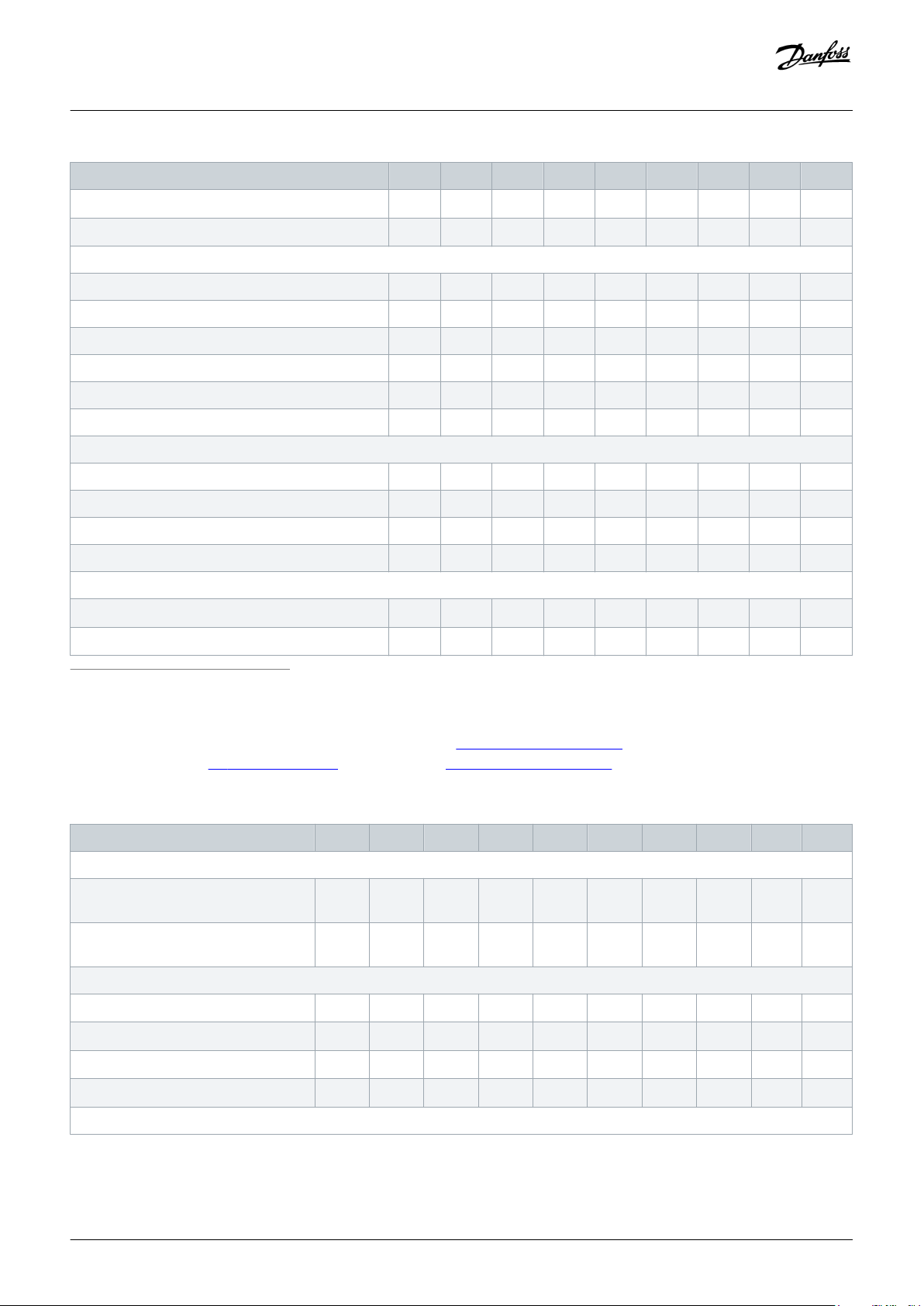
Design Guide | VLT® AutomationDrive FC 301/302
Specifications
Type code P11K P15K P18K P22K P30K P37K P45K P55K P75K
IP55/Type 12
IP66/Type 4X
(2)
(2)
B1 B1 B2 B2 C1 C1 C1 C2 C2
B1 B1 B2 B2 C1 C1 C1 C2 C2
Rated output current
Continuous (380–440 V) [A] 24 32 37.5 44 61 73 90 106 147
Intermittent overload (380–440 V) [A] 38.4 51.2 60 70.4 91.5 110 135 159 221
Continuous (441–500 V) [A] 21 27 34 40 52 65 80 105 130
Intermittent overload (441–500 V) [A] 33.6 43.2 54.4 64 78 97.5 120 158 195
Continuous apparent power (@400 V) [kVA] 16.6 22.2 26 30.5 42.3 50.6 62.4 73.4 102
Continuous apparent power (@460 V) [kVA] 16.7 21.5 27.1 31.9 41.4 51.8 63.7 83.7 104
Maximum input current
Continuous (380–440 V) [A] 22 29 34 40 55 66 82 96 133
Intermittent overload (380–440 V) [A] 35.2 46.4 54.4 64 82.5 99 123 144 200
Continuous (441–500 V) [A] 19 25 31 36 47 59 73 95 118
Intermittent overload (441–500 V) [A] 30.4 40 49.6 57.6 70.5 88.5 110 143 177
More specifications
Power loss at rated maximum load estimated
Efficiency at rated output current
1
Enclosure size A1 is only available as FC 301.
2
Enclosure size A4 is only available without C and D option, or without C option but with backplate.
3
Applies to dimensioning of drive cooling. If the switching frequency is higher than the default setting, the power losses may increase. LCP and typical control card power consump-
tions is included. For power loss data according to IEC 61800-9-2, and EN 50598-2, refer to http://ecosmart.danfoss.com/.
4
For energy efficiency class, see
Table 34: Mains Supply 3x380–480 V AC (FC 301 T4) and 3x380–500 V AC (FC 302 T5), Normal Overload, 0.37–7.5 kW
8.5 Ambient Conditions. For part load losses, see http://ecosmart.danfoss.com/.
(4)
(3)
291 379 444 547 570 697 891 1022 1232
[W]
0.98 0.98 0.98 0.98 0.98 0.98 0.98 0.98 0.99
Type code PK37 PK55 PK75 P1K1 P1K5 P2K2 P3K0 P4K0 P5K5 P7K5
Intermittent overload classification 160% (0.37–22 kW), 150% (30–75 kW) for 1 minute/10 minutes
Typical shaft output power [kW
0.37 0.55 0.75 1.1 1.5 2.2 3.0 4.0 5.5 7.5
@400 V]
Typical shaft output power [hp
0.5 0.75 1.0 1.5 2.0 3.0 4.0 5.0 7.5 10
@460 V]
Protection rating IEC/UL [enclosure size]
IP20/Chassis
IP21/Type 1
IP55/Type 12
IP66/Type 4X
(1)
(1)
(2)
(2)
A1/A2 A1/A2 A1/A2 A1/A2 A1/A2 A2 A2 A2 A3 A3
A1/A2 A1/A2 A1/A2 A1/A2 A1/A2 A2 A2 A2 A3 A3
A4/A5 A4/A5 A4/A5 A4/A5 A4/A5 A4/A5 A4/A5 A4/A5 A5 A5
A4/A5 A4/A5 A4/A5 A4/A5 A4/A5 A4/A5 A4/A5 A4/A5 A5 A5
Rated output current
Danfoss A/S © 2019.10
AJ286655760917en-000101 / 130R0301| 99
Page 100

Design Guide | VLT® AutomationDrive FC 301/302
Specifications
Type code PK37 PK55 PK75 P1K1 P1K5 P2K2 P3K0 P4K0 P5K5 P7K5
Continuous (380–440 V) [A] 1.3 1.8 2.4 3.0 4.1 5.6 7.2 10 13 16
Intermittent overload (380–440 V) [A] 1.4 2.0 2.6 3.3 4.5 6.2 7.9 11 14.3 17.6
Continuous (441–500 V) [A] 1.2 1.6 2.1 2.7 3.4 4.8 6.3 8.2 11 14.5
Intermittent overload (441–500 V) [A] 1.3 1.8 2.3 3.0 3.7 5.3 6.9 9.0 12.1 16
Continuous apparent power (@400 V)
0.9 1.3 1.7 2.1 2.8 3.9 5.0 6.9 9.0 11
[kVA]
Continuous apparent power (@460 V)
0.9 1.3 1.7 2.4 2.7 3.8 5.0 6.5 8.8 11.6
[kVA]
Maximum input current
Continuous (380–440 V) [A] 1.2 1.6 2.2 2.7 3.7 5.0 6.5 9.0 11.7 14.4
Intermittent overload (380–440 V) [A] 1.3 1.8 2.4 3.0 4.1 5.5 7.2 9.9 12.9 15.8
Continuous (441–500 V) [A] 1.0 1.4 1.9 2.7 3.1 4.3 5.7 7.4 9.9 13
Intermittent overload (441–500 V) [A] 1.1 1.5 2.1 3.0 3.4 4.7 6.3 8.1 10.9 14.3
More specifications
Power loss at rated maximum load es-
(3)
timated
Efficiency at rated output current
1
Enclosure size A1 is only available as FC 301.
2
Enclosure size A4 is only available without C and D option, or without C option but with backplate.
3
Applies to dimensioning of drive cooling. If the switching frequency is higher than the default setting, the power losses may increase. LCP and typical control card power consump-
tion is included. For power loss data according to IEC 61800-9-2, and EN 50598-2, refer to http://ecosmart.danfoss.com/.
4
For energy efficiency class, see
[W]
(4)
8.5 Ambient Conditions. For part load losses, see http://ecosmart.danfoss.com/.
35 42 46 58 62 88 116 124 187 255
0.93 0.95 0.96 0.96 0.97 0.97 0.97 0.97 0.97 0.97
Table 35: Mains Supply 3x380–480 V AC (FC 301 T4) and 3x380–500 V AC (FC 302 T5), Normal Overload, 11–75 kW
Type code P11K P15K P18K P22K P30K P37K P45K P55K P75K
Intermittent overload classification 160% (0.37–22 kW), 150% (30–75 kW) for 1 minute/10 minutes
Typical shaft output power [kW @400 V] 11 15 18.5 22 30 37 45 55 75
Typical shaft output power [hp @460 V] 15 20 25 30 40 50 60 75 100
Protection rating IEC/UL [enclosure size]
IP20/Chassis
IP21/Type 1
IP55/Type 12
IP66/Type 4X
(1)
(1)
(2)
(2)
B3 B3 B4 B4 B4 C3 C3 C4 C4
B1 B1 B2 B2 C1 C1 C1 C2 C2
B1 B1 B2 B2 C1 C1 C1 C2 C2
B1 B1 B2 B2 C1 C1 C1 C2 C2
Rated output current
Continuous (380–440 V) [A] 32 37.5 44 61 73 90 106 147 177
Intermittent overload (380–440 V) [A] 26.4 35.2 41.3 48.4 67.1 80.3 99 117 162
Continuous (441–500 V) [A] 27 34 40 52 65 80 105 130 160
100 | Danfoss A/S © 2019.10
AJ286655760917en-000101 / 130R0301
 Loading...