

Page 1
ENGINEERING TOMORROW
Programming Guide
VLT® AutomationDrive FC 301/302
Software versions, control card MK I: 7.62, 48.2X
Software version, control card MK II: 8.10
www.DanfossDrives.com
Page 2

Page 3

Contents Programming Guide
Contents
1 Introduction
1.1 Software Version
1.2 Approvals
1.3 Denitions
1.3.1 Frequency Converter 4
1.3.2 Input 4
1.3.3 Motor 4
1.3.4 References 5
1.3.5 Miscellaneous 5
1.4 Safety
1.5 Electrical Wiring
1.6 Integrated Motion Controller
2 How to Program
2.1 Graphical and Numerical Local Control Panels
2.1.1 LCD Display 14
2.1.2 Quick Transfer of Parameter Settings between Multiple Frequency Converters 16
4
4
4
4
7
9
12
13
13
2.1.3 Display Mode 16
2.1.4 Display Mode - Selection of Readouts 16
2.1.5 Parameter Set-up 18
2.1.6 Quick Menu Key Functions 18
2.1.7 Initial Commissioning 19
2.1.8 Main Menu Mode 20
2.1.9 Parameter Selection 20
2.1.10 Changing Data 20
2.1.11 Changing a Text Value 21
2.1.12 Changing a Data Value 21
2.1.13 Innitely Variable Change of Numeric Data Value 21
2.1.14 Value, Step by Step 21
2.1.15 Readout and Programming of Indexed Parameters 22
2.1.16 How to Program on the Numerical Local Control Panel 22
2.1.17 LCP Keys 23
3 Parameter Descriptions
3.1 Parameters: 0-** Operation and Display
25
25
3.2 Parameters: 1-** Load and Motor
3.3 Parameters: 2-** Brakes
MG33MO22 Danfoss A/S © 01/2018 All rights reserved.
37
64
Page 4

Contents
VLT® AutomationDrive FC 301/302
3.4 Parameters: 3-** Reference/Ramps
3.5 Parameters: 4-** Limits/Warnings
3.6 Parameters: 5-** Digital In/Out
3.7 Parameters: 6-** Analog In/Out
3.8 Parameters: 7-** Controllers
3.9 Parameters: 8-** Communications and Options
3.10 Parameters: 9-** PROFIBUS
3.11 Parameters: 10-** DeviceNet CAN Fieldbus
3.12 Parameters: 12-** Ethernet
3.13 Parameters: 13-** Smart Logic Control
3.14 Parameters: 14-** Special Functions
3.15 Parameters: 15-** Drive Information
3.16 Parameters: 16-** Data Readouts
3.17 Parameters: 17-** Feedback
3.18 Parameters: 18-** Data Readouts 2
3.19 Parameters: 19-** Application Parameters
3.20 Parameters: 23-** Time-based Functions
71
84
95
120
130
141
151
151
151
152
176
188
196
204
212
215
215
3.21 Parameters: 30-** Special Features
3.22 Parameters: 32-** MCO Basic Settings
3.23 Parameters: 33-** MCO Advanced Settings
3.24 Parameters: 34-** MCO Data Readouts
3.25 Parameters: 35-** Sensor Input Option
3.26 Parameters: 36-** Programmable I/O Option
3.27 Parameters: 40-** Special Settings
3.28 Parameters: 42-** Safety Functions
3.29 Parameters: 43-** Unit Readouts
4 Integrated Motion Controller
4.1 Introduction
4.2 Positioning, Homing, Synchronization
4.3 Control
5 Parameter Lists
5.1 Introduction
5.2 Parameter Lists and Options, Software Version 8.10 (Standard)
223
227
227
227
227
230
233
233
233
236
236
237
239
242
242
243
5.3 Parameter Lists and Options, Software Version 48.20 (IMC)
6 Troubleshooting
6.1 Status Messages
Danfoss A/S © 01/2018 All rights reserved. MG33MO22
274
297
297
Page 5

Contents Programming Guide
7 Appendix
7.1 Symbols, Abbreviations, and Conventions
Index
312
312
314
MG33MO22 Danfoss A/S © 01/2018 All rights reserved.
Page 6
Introduction
VLT® AutomationDrive FC 301/302
11
1 Introduction
1.1 Software Version
Programming Guide
Software versions:
Control card MK I: 7.62, 48.2X, and earlier versions
Control card MK II: 8.10
The software version number can be read from
parameter 15-43 Software Version.
Table 1.1 Software Version
1.1.1 Control Card MK II
Software version 8.03 and later can only be installed on
control card MK II. Software version 7.62 and earlier can
only be installed on control card MK I. Identify the control
card version by the color of the USB port:
MK I: Black USB port.
MK II: White USB port.
1.2 Approvals
1.3 Denitions
1.3.1 Frequency Converter
I
VLT,MAX
Maximum output current.
I
VLT,N
Rated output current supplied by the frequency converter.
U
VLT,MAX
Maximum output voltage.
1.3.2 Input
Control command
Start and stop the connected motor with LCP and digital
inputs.
Functions are divided into 2 groups.
Functions in group 1 have higher priority than functions in
group 2.
Group 1 Reset, coast stop, reset and coast stop, quick stop,
DC brake, stop, the [OFF] key.
Group 2 Start, pulse start, reversing, start reversing, jog,
freeze output.
Table 1.2 Function Groups
1.3.3 Motor
Motor running
Torque generated on output shaft and speed from 0 RPM
to maximum speed on motor.
f
JOG
Motor frequency when the jog function is activated (via
digital terminals).
f
M
Motor frequency.
f
MAX
Maximum motor frequency.
f
MIN
Minimum motor frequency.
f
M,N
Rated motor frequency (nameplate data).
I
M
Motor current (actual).
I
M,N
Rated motor current (nameplate data).
n
M,N
Nominal motor speed (nameplate data).
n
s
Synchronous motor speed.
2 × par . 1 − 23 × 60s
ns=
n
slip
Motor slip.
P
M,N
Rated motor power (nameplate data in kW or hp).
T
M,N
Rated torque (motor).
U
M
Instant motor voltage.
U
M,N
Rated motor voltage (nameplate data).
par . 1 − 39
4 Danfoss A/S © 01/2018 All rights reserved. MG33MO22
Page 7

175ZA078.10
Pull-out
RPM
Torque
Introduction Programming Guide
1 1
Break-away torque
Figure 1.1 Break-away Torque
η
VLT
The eciency of the frequency converter is dened as the
ratio between the power output and the power input.
Start-disable command
A stop command belonging to Group 1 control commands
- see Table 1.2.
Stop command
A stop command belonging to Group 1 control commands
- see Table 1.2.
1.3.4 References
Analog reference
A signal transmitted to the analog inputs 53 or 54 (voltage
or current).
Binary reference
A signal transmitted to the serial communication port.
Preset reference
A dened preset reference to be set from -100% to +100%
of the reference range. Selection of 8 preset references via
the digital terminals.
Pulse reference
A pulse frequency signal transmitted to the digital inputs
(terminal 29 or 33).
Ref
MAX
Determines the relationship between the reference input at
100% full scale value (typically 10 V, 20 mA) and the
resulting reference. The maximum reference value is set in
parameter 3-03 Maximum Reference.
Ref
MIN
Determines the relationship between the reference input at
0% value (typically 0 V, 0 mA, 4 mA) and the resulting
reference. The minimum reference value is set in
parameter 3-02 Minimum Reference.
1.3.5 Miscellaneous
Analog inputs
The analog inputs are used for controlling various
functions of the frequency converter.
There are 2 types of analog inputs:
Current input, 0–20 mA, and 4–20 mA
Voltage input, -10 V DC to +10 V DC.
Analog outputs
The analog outputs can supply a signal of 0–20 mA, 4–20
mA.
Automatic motor adaptation, AMA
AMA algorithm determines the electrical parameters for
the connected motor at standstill.
Brake resistor
The brake resistor is a module capable of absorbing the
brake power generated in regenerative braking. This
regenerative brake power increases the DC-link voltage
and a brake chopper ensures that the power is transmitted
to the brake resistor.
CT characteristics
Constant torque characteristics used for all applications
such as conveyor belts, displacement pumps, and cranes.
Digital inputs
The digital inputs can be used for controlling various
functions of the frequency converter.
Digital outputs
The frequency converter features 2 solid-state outputs that
can supply a 24 V DC (maximum 40 mA) signal.
DSP
Digital signal processor.
ETR
Electronic thermal relay is a thermal load calculation based
on present load and time. Its purpose is to estimate the
motor temperature.
Hiperface
Hiperface® is a registered trademark by Stegmann.
Initializing
If initializing is carried out (parameter 14-22 Operation
Mode), the frequency converter returns to the default
setting.
®
MG33MO22 Danfoss A/S © 01/2018 All rights reserved. 5
Page 8

Introduction
VLT® AutomationDrive FC 301/302
11
Intermittent duty cycle
An intermittent duty rating refers to a sequence of duty
cycles. Each cycle consists of an on-load and an o-load
period. The operation can be either periodic duty or nonperiodic duty.
LCP
The local control panel makes up a complete interface for
control and programming of the frequency converter. The
control panel is detachable and can be installed up to 3 m
(10 ft) from the frequency converter, that is, in a front
panel with the installation kit option.
NLCP
Numerical local control panel interface for control and
programming of the frequency converter. The display is
numerical and the panel is used to show process values.
The NLCP has no storage and copy functions.
lsb
Least signicant bit.
msb
Most signicant bit.
MCM
Short for mille circular mil, an American measuring unit for
cable cross-section. 1 MCM=0.5067 mm2.
Online/oine parameters
Changes to online parameters are activated immediately
after the data value is changed. Press [OK] to activate
changes to o-line parameters.
Process PID
The PID control maintains the required speed, pressure,
temperature, and so on, by adjusting the output frequency
to match the varying load.
PCD
Process control data.
Power cycle
Switch o the mains until display (LCP) is dark, then turn
power on again.
Pulse input/incremental encoder
An external, digital pulse transmitter used for feeding back
information on motor speed. The encoder is used in
applications where great accuracy in speed control is
required.
RCD
Residual current device.
Set-up
Save parameter settings in 4 set-ups. Change between the
4 parameter set-ups and edit 1 set-up, while another setup is active.
SFAVM
Switching pattern called stator ux-oriented asynchronous
vector modulation (parameter 14-00 Switching Pattern).
Slip compensation
The frequency converter compensates for the motor slip by
giving the frequency a supplement that follows the
measured motor load keeping the motor speed almost
constant.
SLC
The SLC (smart logic control) is a sequence of user-dened
actions executed when the associated user-dened events
are evaluated as true by the SLC. (See
chapter 3.13 Parameters: 13-** Smart Logic Control).
STW
Status word.
FC standard bus
Includes RS485 bus with FC protocol or MC protocol. See
parameter 8-30 Protocol.
THD
Total harmonic distortion states the total contribution of
harmonic.
Thermistor
A temperature-dependent resistor placed on the frequency
converter or the motor.
Trip
A state entered in fault situations, for example if the
frequency converter is subject to an overtemperature or
when the frequency converter is protecting the motor,
process, or mechanism. The frequency converter prevents a
restart until the cause of the fault has disappeared. To
cancel the trip state, restart the frequency converter. Do
not use the trip state for personal safety.
Trip lock
The frequency converter enters this state in fault situations
to protect itself. The frequency converter requires physical
intervention, for example when there is a short circuit on
the output. A trip lock can only be canceled by disconnecting mains, removing the cause of the fault, and
reconnecting the frequency converter. Restart is prevented
until the trip state is canceled by activating reset or,
sometimes, by being programmed to reset automatically.
Do not use the trip lock state for personal safety.
VT characteristics
Variable torque characteristics used for pumps and fans.
+
VVC
If compared with standard voltage/frequency ratio control,
voltage vector control (VVC+) improves the dynamics and
the stability, both when the speed reference is changed
and in relation to the load torque.
60° AVM
60° asynchronous vector modulation
(parameter 14-00 Switching Pattern).
6 Danfoss A/S © 01/2018 All rights reserved. MG33MO22
Page 9

Introduction Programming Guide
1 1
Power factor
The power factor is the relation between I1 and I
2
+ I
1
3xUxI1cosϕ
3xUxI
I1xcosϕ1
I
RMS
2
2
+ I
+ .. + I
5
7
RMS
=
I
1
sincecosϕ1 = 1
I
RMS
2
n
RMS
Power factor =
The power factor for 3-phase control:
Power factor =
The power factor indicates to which extent the frequency
converter imposes a load on the mains supply.
The lower the power factor, the higher the I
same kW performance.
I
=
RMS
In addition, a high-power factor indicates that the dierent
harmonic currents are low.
The DC coils in the frequency converters produce a highpower factor, which minimizes the imposed load on the
mains supply.
Target position
The nal target position specied by positioning
commands. The prole generator uses this position to
calculate the speed prole.
Commanded position
The actual position reference calculated by the prole
generator. The frequency converter uses the commanded
position as setpoint for position PI.
Actual position
The actual position from an encoder, or a value that the
motor control calculates in open loop. The frequency
converter uses the actual position as feedback for position
PI.
Position error
Position error is the dierence between the actual position
and the commanded position. The position error is the
input for the position PI controller.
Position unit
The physical unit for position values.
I
.
RMS
for the
Safety
1.4
WARNING
HIGH VOLTAGE
Frequency converters contain high voltage when
connected to AC mains input, DC supply, or load sharing.
Failure to perform installation, start-up, and maintenance
by qualied personnel can result in death or serious
injury.
Only qualied personnel must perform instal-
•
lation, start-up, and maintenance.
Before performing any service or repair work,
•
use an appropriate voltage measuring device to
make sure that there is no remaining voltage on
the drive.
Safety regulations
Disconnect mains supply to the frequency
•
converter whenever repair work is to be carried
out. Check that the mains supply has been
disconnected and that the necessary time has
elapsed before removing motor and mains supply
plugs. For information about the discharge time,
see Table 1.3.
[O] does not disconnect the mains supply and
•
must not be used as a safety switch.
Ground the equipment properly, protect the user
•
against supply voltage, and protect the motor
against overload in accordance with applicable
national and local regulations.
The ground leakage current exceeds 3.5 mA.
•
Ensure correct grounding of the equipment by a
certied electrical installer.
Do not remove the plugs for the motor and
•
mains supply while the frequency converter is
connected to mains. Check that the mains supply
has been disconnected and that the necessary
time has elapsed before removing motor and
mains plugs.
The frequency converter has more voltage
•
sources than L1, L2, and L3, when load sharing
(linking of DC intermediate circuit) or external
24 V DC is installed. Check that all voltage
sources have been disconnected and that the
necessary time has elapsed before commencing
repair work. For information about the discharge
time, see Table 1.3.
MG33MO22 Danfoss A/S © 01/2018 All rights reserved. 7
Page 10
Introduction
VLT® AutomationDrive FC 301/302
11
WARNING
UNINTENDED START
When the frequency converter is connected to AC mains,
DC supply, or load sharing, the motor may start at any
time. Unintended start during programming, service, or
repair work can result in death, serious injury, or
property damage. The motor can start via an external
switch, a eldbus command, an input reference signal
from the LCP, or after a cleared fault condition.
To prevent unintended motor start:
Disconnect the frequency converter from the
•
mains.
Press [O/Reset] on the LCP before
•
programming parameters.
Completely wire and assemble the frequency
•
converter, motor, and any driven equipment
before connecting the frequency converter to
AC mains, DC supply, or load sharing.
WARNING
DISCHARGE TIME
The frequency converter contains DC-link capacitors,
which can remain charged even when the frequency
converter is not powered. High voltage can be present
even when the warning LED indicator lights are o.
Failure to wait the specied time after power has been
removed before performing service or repair work can
result in death or serious injury.
Stop the motor.
•
Disconnect AC mains and remote DC-link power
•
supplies, including battery back-ups, UPS, and
DC-link connections to other frequency
converters.
Disconnect or lock PM motor.
•
Wait for the capacitors to discharge fully. The
•
minimum duration of waiting time is specied
in Table 1.3 and is also visible on the product
label on top of the frequency converter.
Before performing any service or repair work,
•
use an appropriate voltage measuring device to
make sure that the capacitors are fully
discharged.
Voltage [V] Minimum waiting time (minutes)
4 7 15
200–240 0.25–3.7 kW
(0.34–5 hp)
380–500 0.25–7.5 kW
(0.34–10 hp)
525–600 0.75–7.5 kW
(1–10 hp)
525–690 – 1.5–7.5 kW
Table 1.3 Discharge Time
– 5.5–37 kW
(7.5–50 hp)
– 11–75 kW
(15–100 hp)
– 11–75 kW
(15–100 hp)
(2–10 hp)
(15–100 hp)
11–75 kW
NOTICE!
When using the Safe Torque O, always follow the
instructions in VLT® Frequency Converters - Safe Torque
O Operating Instructions.
NOTICE!
Control signals from, or internally within, the frequency
converter may in rare cases be activated in error, be
delayed, or fail to occur entirely. When used in situations
where safety is critical, for example when controlling the
electromagnetic brake function of a hoist application, do
not rely on these control signals exclusively.
NOTICE!
Hazardous situations must be identied by the machine
builder/integrator who is responsible for considering the
necessary preventive means. More monitoring and
protective devices may be included, always according to
valid national safety regulations, for example law on
mechanical tools and regulations for the prevention of
accidents.
Crane, lifts, and hoists
The controlling of external brakes must always have a
redundant system. The frequency converter can in no
circumstances be the primary safety circuit. Comply with
relevant standards, for example:
Hoists and cranes: IEC 60204-32
Lifts: EN 81
Protection mode
Once a hardware limit on motor current or DC-link voltage
is exceeded, the frequency converter enters the protection
mode. Protection mode means a change of the PWM
modulation strategy and a low switching frequency to
minimize losses. This continues for 10 s after the last fault
and increases the reliability and the robustness of the
frequency converter while re-establishing full control of the
motor.
8 Danfoss A/S © 01/2018 All rights reserved. MG33MO22
Page 11
3 Phase
power
input
DC bus
Switch Mode
Power Supply
Motor
Analog Output
Interface
relay 1
relay 2
ON=Terminated
OFF=Open
Brake
resistor
130BC931.12
91 (L1)
92 (L2)
93 (L3)
PE
88 (-)
89 (+)
50 (+10 V OUT)
53 (A IN)
54 (A IN)
55 (COM A IN)
0/4-20 mA
12 (+24 V OUT)
13 (+24 V OUT)
37 (D IN)
18 (D IN)
20 (COM D IN)
10 V DC
15 mA 130/200 mA
+ - + -
(U) 96
(V) 97
(W) 98
(PE) 99
(COM A OUT) 39
(A OUT) 42
(P RS485) 68
(N RS485) 69
(COM RS485) 61
0V
5V
S801
0/4-20 mA
RS485
RS485
03
+10 V DC
0/-10 V DC -
+10 V DC
+10 V DC
0/4-20 mA
0/-10 V DC -
240 V AC, 2 A
24 V DC
02
01
05
04
06
240 V AC, 2 A
24 V (PNP)
0 V (NPN)
0 V (NPN)
24 V (PNP)
19 (D IN)
24 V (PNP)
0 V (NPN)
27
24 V
0 V
(D IN/OUT)
0 V (NPN)
24 V (PNP)
(D IN/OUT)
0 V
24 V
29
24 V (PNP)
0 V (NPN)
0 V (NPN)
24 V (PNP)
33 (D IN)
32 (D IN)
1 2
ON
S201
ON
21
S202
ON=0/4-20 mA
OFF=0/-10 V DC +10 V DC
95
400 V AC, 2 A
Par. E-00
21
ON
S801
(R+) 82
(R-) 81
: Chassis
: Earth
1)
2)
1)
1)
Introduction Programming Guide
1 1
In hoist applications, protection mode is not usable
because the frequency converter is unable to leave this
mode again and therefore it extends the time before
activating the brake, which is not recommended.
Protection mode can be disabled by setting
parameter 14-26 Trip Delay at Inverter Fault to 0, which
means that the frequency converter trips immediately if 1
of the hardware limits is exceeded.
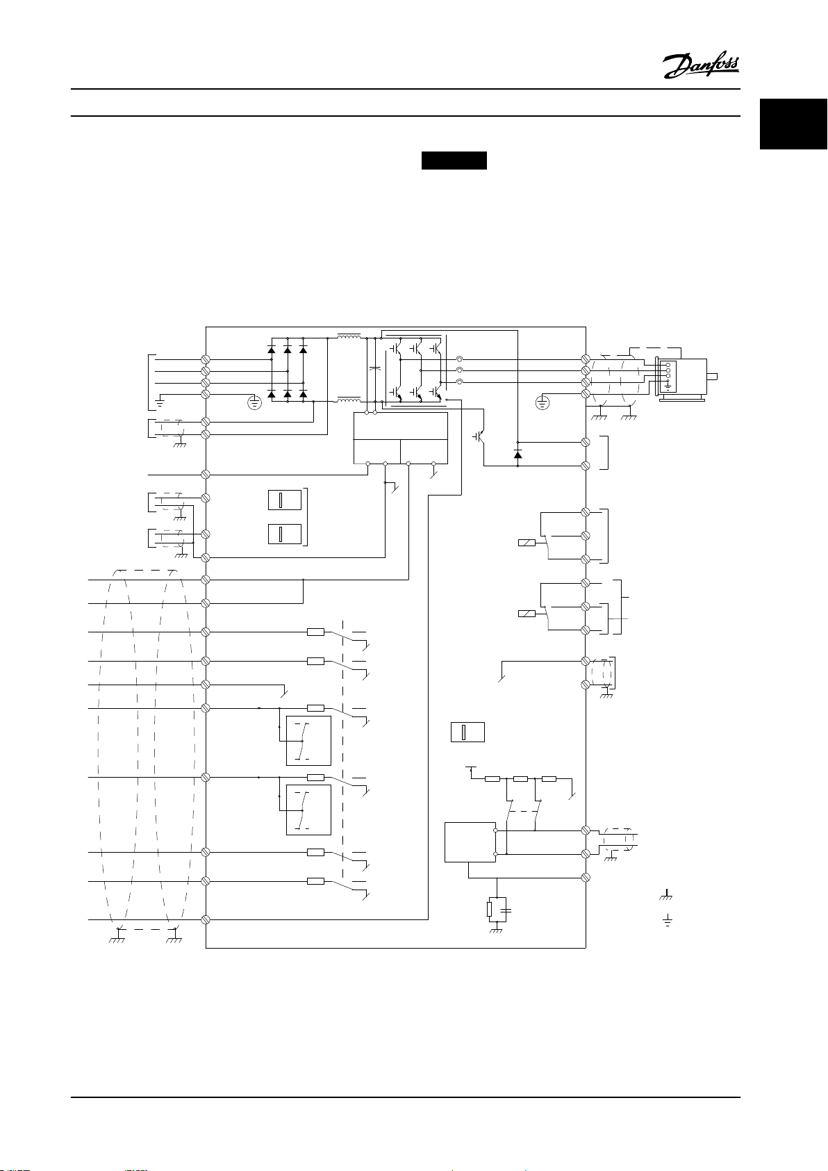
1.5 Electrical Wiring
NOTICE!
Disabling protection mode in hoisting applications
(parameter 14-26 Trip Delay at Inverter Fault = 0) is
recommended.
Figure 1.2 Basic Wiring Schematic Drawing
A=Analog, D=Digital
Terminal 37 is used for Safe Torque O. For Safe Torque O installation instructions, refer to the VLT® Frequency Converters -
Safe Torque O Operating Instructions.
MG33MO22 Danfoss A/S © 01/2018 All rights reserved. 9
Page 12
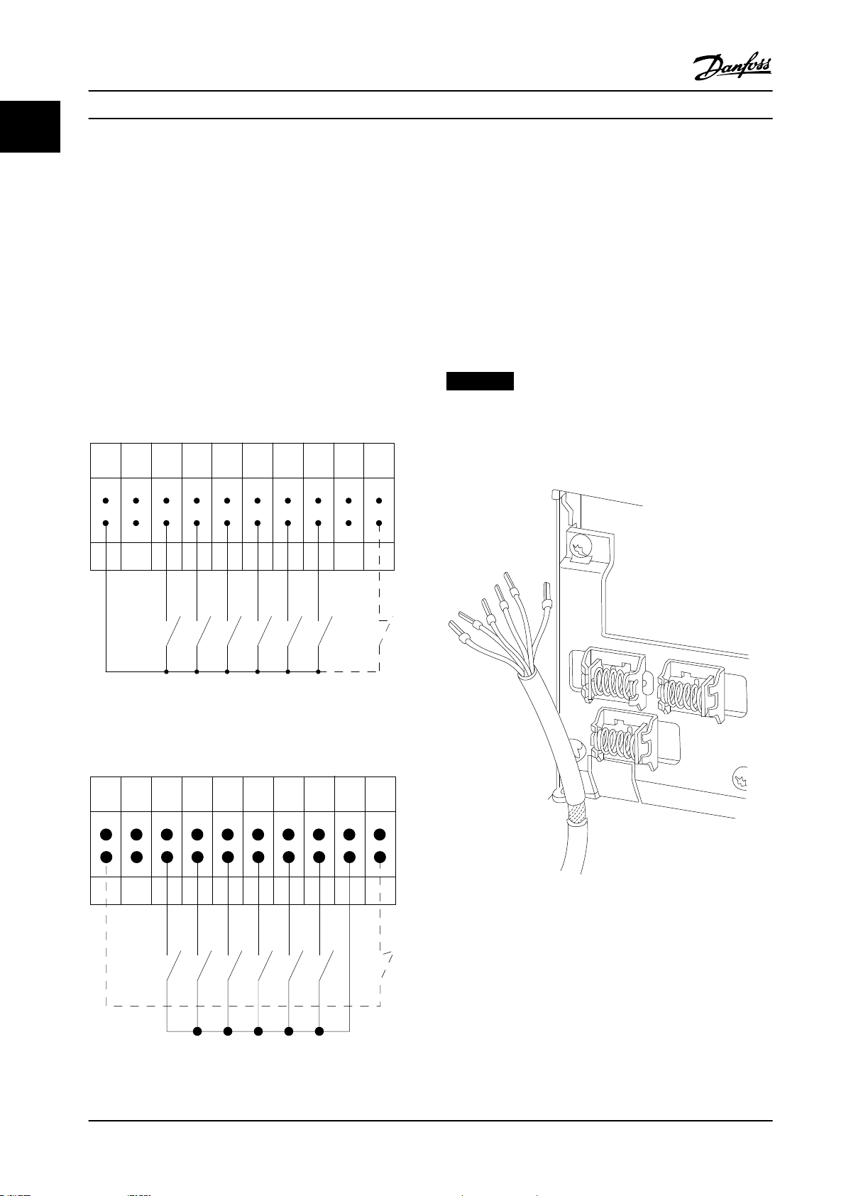
12 13 18 19 27 29 32 33 20 37
+24 V DC
0 VDC
130BT106.10
PNP (Source)
Digital input wiring
NPN (Sink)
Digital input wiring
12 13 18 19 27 29 32 33 20 37
+24 V DC
0 VDC
130BT107.11
130BA681.10
Introduction
VLT® AutomationDrive FC 301/302
11
1) Terminal 37 is not included in FC 301 (except enclosure type A1). Relay 2 and terminal 29 have no function in FC 301.
2) Do not connect cable shield.
Very long control cables and analog signals may in rare cases, and depending on installation, result in 50/60 Hz ground
loops due to noise from mains supply cables.
If 50/60 Hz ground loops occur, consider breaking the shield or insert a 100 nF capacitor between shield and enclosure.
To avoid ground currents from both groups to
aect other groups, connect the digital and analog inputs and outputs
separately to the common inputs (terminals 20, 55, and 39) of the frequency converter. For example, switching on the digital
input may disturb the analog input signal.
Input polarity of control terminals
NOTICE!
Control cables must be shielded/armored.
See the section Grounding of Shielded Control Cables in the
design guide for the correct termination of control cables.
Figure 1.3 PNP (Source)
Figure 1.4 NPN (Sink)
10 Danfoss A/S © 01/2018 All rights reserved. MG33MO22
Figure 1.5 Grounding of Shielded/Armored Control Cables
Page 13
Introduction Programming Guide
1 1
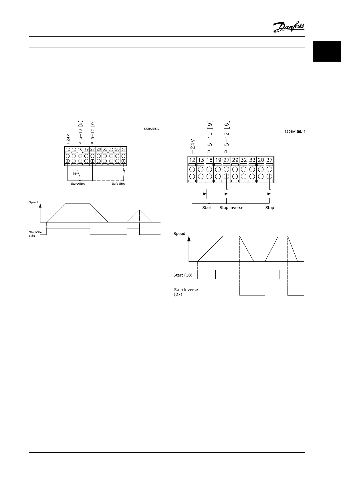
1.5.1 Start/Stop
Terminal 18 = Parameter 5-10 Terminal 18 Digital Input [8]
Start.
Terminal 27 = Parameter 5-12 Terminal 27 Digital Input [0]
No operation (Default [2] Coast inverse).
Terminal 37 = Safe Torque O (where available).
1.5.2 Pulse Start/Stop
Terminal 18 = Parameter 5-10 Terminal 18 Digital Input, [9]
Latched start.
Terminal 27 = Parameter 5-12 Terminal 27 Digital Input, [6]
Stop inverse.
Terminal 37 = Safe Torque O (where available).
Figure 1.6 Start/Stop
Figure 1.7 Pulse Start/Stop
MG33MO22 Danfoss A/S © 01/2018 All rights reserved. 11
Page 14
12
18
27
29
32
37
+24V
Par. 5-10
Par. 5-12
Par. 5-13
Par. 5-14
130BA021.12
130BA154.11
Speed RPM
P 6-15
Ref. voltage
P 6-11 10 V
1 kΩ
+10 V/30 mA
Introduction
VLT® AutomationDrive FC 301/302
11
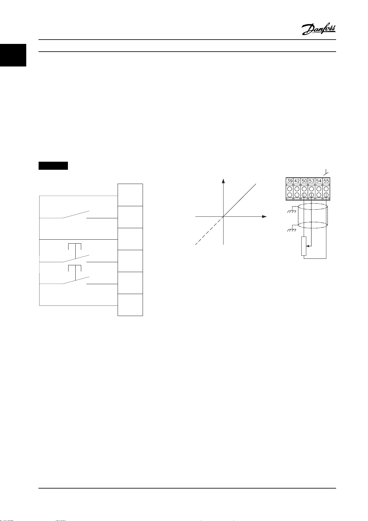
1.5.3 Speed up/Speed Down
Terminals 29/32 = Speed up/Speed down
Terminal 18 = Parameter 5-10 Terminal 18 Digital
Input [9] Start (default).
Terminal 27 = Parameter 5-12 Terminal 27 Digital
Input [19] Freeze reference.
Terminal 29 = Parameter 5-13 Terminal 29 Digital
Input [21] Speed up.
Terminal 32 = Parameter 5-14 Terminal 32 Digital
Input [22] Speed down.
NOTICE!
Terminal 29 only in FC x02 (x=series type).
1.5.4 Potentiometer Reference
Voltage reference via a potentiometer
Reference source 1 = [1] Analog input 53 (default).
Terminal 53, low voltage = 0 V.
Terminal 53, high voltage = 10 V.
Terminal 53, low reference/feedback = 0 RPM.
Terminal 53, high reference/feedback = 1500 RPM.
Switch S201 = OFF (U)
Figure 1.8 Speed up/Speed down
Figure 1.9 Potentiometer Reference
1.6 Integrated Motion Controller
The integrated motion controller (IMC) enables position
control. For more information about IMC, see
chapter 4 Integrated Motion Controller.
12 Danfoss A/S © 01/2018 All rights reserved. MG33MO22
Page 15
Auto
on
Reset
Hand
on
O
Status
Quick
Menu
Main
Menu
Alarm
Log
Back
Cancel
Info
OK
Status
1(0)
1234rpm 10,4A 43,5Hz
Run OK
43,5Hz
On
Alarm
Warn.
130BA018.13
1
2
3
4
b
a
c
How to Program Programming Guide
2 How to Program
2.1 Graphical and Numerical Local Control
Panels
Easy programming of the frequency converter is done via
the graphical LCP (LCP 102). For information about using
the numerical local control panel (LCP 101), see
chapter 2.1.16 How to Program on the Numerical Local
Control Panel.
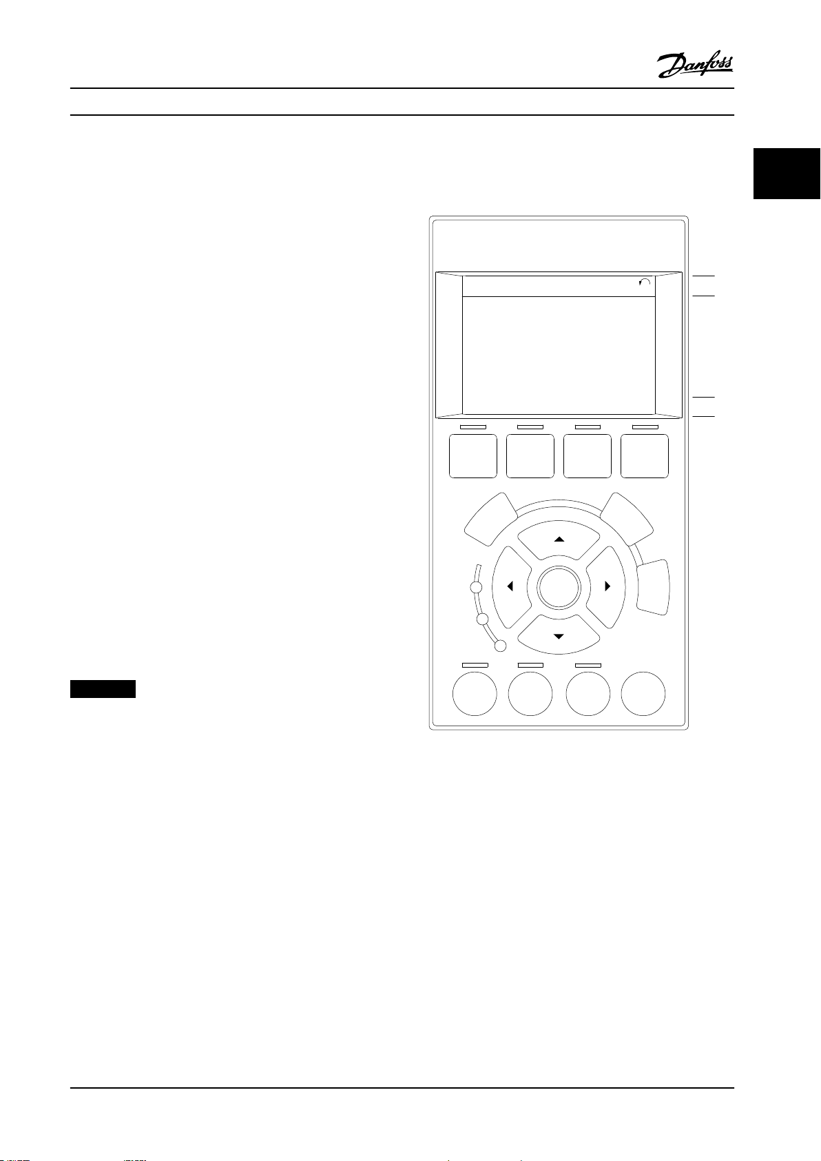
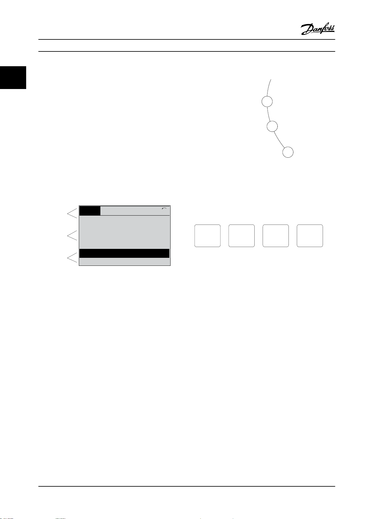
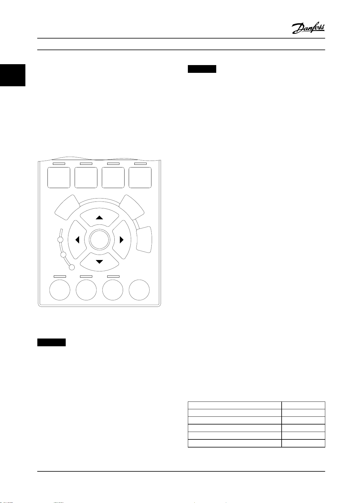
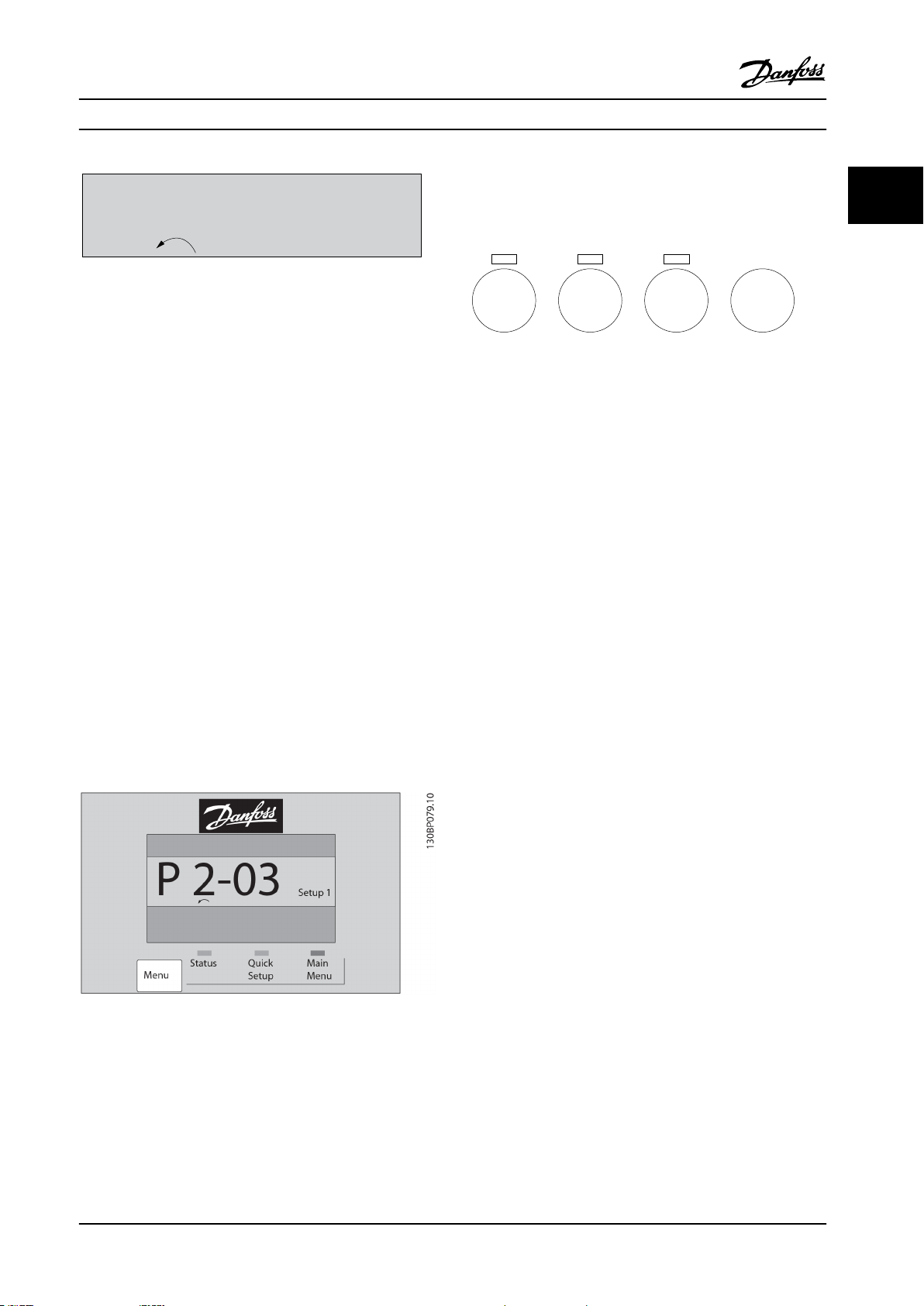
The LCP is divided into 4 functional groups:
1. Graphical display with status lines.
2. Menu keys and indicator lights - changing
parameters and switching between display
functions.
3. Navigation keys and indicator lights.
4. Operation keys and indicator lights.
The LCP display can show up to 5 items of operating data
while showing Status.
Display lines:
a. Status line: Status messages showing icons and
graphics.
b. Line 1–2: Operator data lines showing data
dened or selected. Add up to 1 extra line by
pressing [Status].
c. Status line: Status messages showing text.
2 2
NOTICE!
If start-up is delayed, the LCP shows the INITIALIZING
message until it is ready. Adding or removing options
can delay the start-up.
MG33MO22 Danfoss A/S © 01/2018 All rights reserved. 13
Figure 2.1 LCP
Page 16
Top section
Middle section
Bottom section
Status
43 RPM
1.4 Hz
Auto Remote Running
! Pwr.card temp (W29)
2.9%
5.44 A 25.3 kW
1(1)
130BP074.10
!
On
Warn.
Alarm
130BP044.10
130BP045.10
Status
Quick
Menu
Main
Menu
Alarm
Log
How to Program
VLT® AutomationDrive FC 301/302
2.1.1 LCD Display
Flashing Red LED/Alarm: Indicates an alarm.
•
22
The display has backlight and a total of 6 alpha-numeric
lines. The display lines show the direction of rotation
(arrow), the selected set-up, and the programming set-up.
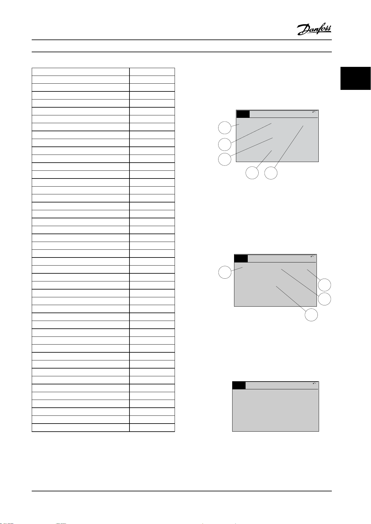
The display is divided into 3 sections.
Top section
The top section shows up to 2 measurements in normal
operating status.
Middle section
The top line shows up to 5 measurements with related
unit, regardless of status (except in the case of alarm/
warning).
Bottom section
The bottom section always shows the state of the
frequency converter in Status mode.
Figure 2.3 Indicator Lights
LCP keys
The control keys are divided into functions. The keys below
the display and indicator lights are used for parameter setup, including option of display indication during normal
operation.
Figure 2.4 LCP Keys
Figure 2.2 Display
The active set-up (selected as the active set-up in
parameter 0-10 Active Set-up) is shown. When programming
another set-up than the active set-up, the number of the
programmed set-up appears to the right.
Display contrast adjustment
Press [Status] and [▲] for darker display.
Press [Status] and [▼] for brighter display.
Most parameter set-ups can be changed immediately via
the LCP, unless a password has been created via
parameter 0-60 Main Menu Password or via
parameter 0-65 Quick Menu Password.
Indicator lights
If certain threshold values are exceeded, the alarm and/or
warning indicator lights up. A status and alarm text appear
on the LCP.
The ON indicator light is activated when the frequency
converter receives mains voltage or via a DC bus terminal
or 24 V external supply. At the same time, the back
indicator light is on.
Green LED/On: Control section is working.
•
Yellow LED/Warn: Indicates a warning.
•
14 Danfoss A/S © 01/2018 All rights reserved. MG33MO22
[Status]
Indicates the status of the frequency converter and/or the
motor. Select between 3 dierent readouts by pressing
[Status]: 5 line readouts, 4 line readouts, or smart logic
control.
Press [Status] for selecting the mode of display or for
changing back to display mode from either the quick
menu mode, the main menu mode, or the alarm mode.
Also use [Status] to toggle single or double readout mode.
[Quick Menu]
Allows quick access to dierent quick menus such as:
My personal menu.
•
Quick set-up.
•
Changes made.
•
Loggings.
•
Press [Quick Menu] to program the parameters belonging
to the Quick Menu. It is possible to switch directly
between quick menu mode and main menu mode.
[Main Menu]
Is used for programming all parameters.
It is possible to switch directly between main menu mode
and quick menu mode.
Page 17

B
a
c
k
C
a
n
c
e
l
I
n
f
o
130BP046.10
Hand
on
O
Auto
on
Reset
How to Program Programming Guide
Parameter shortcut can be carried out by pressing down
[Main Menu] for 3 s. The parameter shortcut allows direct
access to any parameter.
[Alarm Log]
Shows an alarm list of the 5 latest alarms (numbered A1–
A5). To obtain extra details about an alarm, press the
navigation keys to maneuver to the alarm number and
press [OK]. Information is shown about the condition of
the frequency converter before it enters the alarm mode.
[Back]
Returns to the previous step or layer in the navigation
structure.
[Cancel]
Last change or command is canceled as long as the display
has not been changed.
[Info]
Supplies information about a command, parameter, or
function in any display window. [Info] provides detailed
information whenever help is needed.
Exit Info mode by pressing either [Info], [Back], or [Cancel].
Figure 2.5 Back
Figure 2.6 Cancel
Figure 2.7 Info
Navigation keys
The 4 navigation keys are used to navigate between the
dierent options available in Quick Menu, Main Menu, and
Alarm Log. Press the keys to move the cursor.
[OK]
Press for selecting a parameter marked by the cursor and
for enabling the change of a parameter.
Local control keys
Local control keys are at the bottom of the LCP.
Figure 2.8 Local Control Keys
[Hand On]
Enables control of the frequency converter via the LCP.
[Hand On] also starts the motor, and it is now possible to
enter the motor speed data with the navigation keys. The
key can be selected as [1] Enable or [0] Disable via
parameter 0-40 [Hand on] Key on LCP.
External stop signals activated with control signals or a
eldbus override a start command via the LCP.
The following control signals are still active when [Hand
On] is activated:
[Hand on] - [O] - [Auto On].
•
Reset.
•
Coast stop inverse.
•
Reversing.
•
Set-up select bit 0 - Set-up select bit 1.
•
Stop command from serial communication.
•
Quick stop.
•
DC brake.
•
[O]
Stops the connected motor. The key can be selected as [1]
Enable or [0] Disable via parameter 0-41 [O] Key on LCP. If
no external stop function is selected and the [O] key is
inactive, the motor can be stopped by disconnecting the
voltage.
[Auto On]
Enables the frequency converter to be controlled via the
control terminals and/or serial communication. When a
start signal is applied on the control terminals and/or the
bus, the frequency converter starts. The key can be
selected as [1] Enable or [0] Disable via
parameter 0-42 [Auto on] Key on LCP.
NOTICE!
An active HAND-OFF-AUTO signal via the digital inputs
has higher priority than the control keys [Hand On] –
[Auto On].
[Reset]
Is used for resetting the frequency converter after an alarm
(trip). It can be selected as [1] Enable or [0] Disable via
parameter 0-43 [Reset] Key on LCP.
2 2
MG33MO22 Danfoss A/S © 01/2018 All rights reserved. 15
Page 18
Auto
on
Reset
Hand
on
O
Status
Quick
Menu
Main
Menu
Alarm
Log
Back
Cancel
Info
OK
On
Alarm
Warn.
130BA027.10
How to Program
VLT® AutomationDrive FC 301/302
The parameter shortcut can be carried out by pressing
22
down the [Main Menu] key for 3 s. The parameter shortcut
provides direct access to any parameter.
2.1.2 Quick Transfer of Parameter Settings
between Multiple Frequency
Converters
Once the set-up of a frequency converter is complete,
store the data in the LCP or on a PC via MCT 10 Set-up
Software.
NOTICE!
Stop the motor before performing this operation.
To transfer the data from the LCP to the frequency
converter:
1. Go to parameter 0-50 LCP Copy.
2. Press the [OK] key.
3. Select [2] All from LCP.
4. Press the [OK] key.
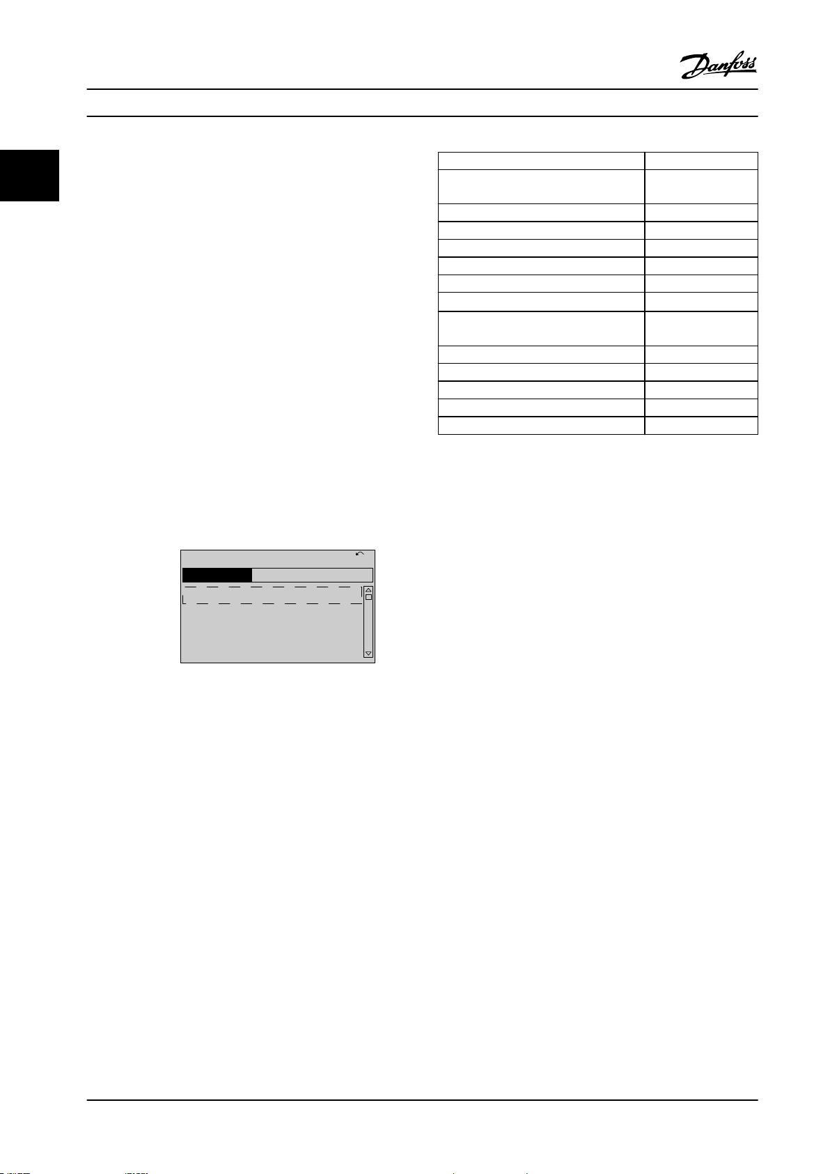
The parameter settings stored in the LCP are now
transferred to the frequency converter indicated by the
progress bar. When 100% is reached, press [OK].
2.1.3 Display Mode
In normal operation, up to 5 dierent operating variables
can be indicated continuously in the middle section: 1.1,
1.2, and 1.3, as well as 2 and 3.
2.1.4 Display Mode - Selection of Readouts
orstår detIt is possible to toggle between 3 status readout
screens by pressing [Status].
Operating variables with dierent formatting are shown in
each status view further in this section.
Figure 2.9 LCP
Data storage in LCP
NOTICE!
Stop the motor before performing this operation.
To store the data in the LCP:
1. Go to parameter 0-50 LCP Copy.
2. Press the [OK] key.
3. Select [1] All to LCP.
4. Press the [OK] key.
All parameter settings are now stored in the LCP indicated
by the progress bar. When 100% is reached, press [OK].
Connect the LCP to another frequency converter and copy
the parameter settings to this frequency converter as well.
Data transfer from LCP to frequency converter
Table 2.1 shows the measurements that can be linked to
each of the operating variables. When options are
mounted, additional measurements are available.
Dene the links via
Parameter 0-20 Display Line 1.1 Small.
•
Parameter 0-21 Display Line 1.2 Small.
•
Parameter 0-22 Display Line 1.3 Small.
•
Parameter 0-23 Display Line 2 Large.
•
Parameter 0-24 Display Line 3 Large.
•
Each readout parameter selected in parameter 0-20 Display
Line 1.1 Small to parameter 0-24 Display Line 3 Large has its
own scale and digits after a possible decimal point. The
larger the numeric value of a parameter is, the fewer digits
are shown after the decimal point.
Example: Current readout 5.25 A, 15.2 A, 105 A.
Operating variable Unit
Parameter 16-00 Control Word hex
Parameter 16-01 Reference [Unit] [Unit]
Parameter 16-02 Reference [%] %
Parameter 16-03 Status Word hex
Parameter 16-05 Main Actual Value [%] %
16 Danfoss A/S © 01/2018 All rights reserved. MG33MO22
Page 19
1.1
2
3
1.3
1.2
130BP041.10
799 RPM
Auto Remote Ramping
1 (1)
36.4 kW7.83 A
0.000
53.2%
Status
1.1
1.2
2
1.3
130BP062.10
207RPM
Auto Remote Running
1 (1)
24.4 kW5.25A
6.9Hz
Status
130BP063.10
778 RPM
Auto Remote Running
1 (1)
4.0 kW0.86 A
State: 0 o 0 (o)
When: Do: -
Status
How to Program Programming Guide
Operating variable Unit
Parameter 16-10 Power [kW] [kW]
Parameter 16-11 Power [hp] [hp]
Parameter 16-12 Motor Voltage [V ]
Parameter 16-13 Frequency [Hz]
Parameter 16-14 Motor current [A]
Parameter 16-16 Torque [Nm] Nm
Parameter 16-17 Speed [RPM] [RPM]
Parameter 16-18 Motor Thermal %
Parameter 16-20 Motor Angle
Parameter 16-30 DC Link Voltage V
Parameter 16-32 Brake Energy /s kW
Parameter 16-33 Brake Energy Average kW
Parameter 16-34 Heatsink Temp.
Parameter 16-35 Inverter Thermal %
Parameter 16-36 Inv. Nom. Current A
Parameter 16-37 Inv. Max. Current A
Parameter 16-38 SL Controller State
Parameter 16-39 Control Card Temp.
Parameter 16-40 Logging Buer Full
Parameter 16-50 External Reference
Parameter 16-51 Pulse Reference
Parameter 16-52 Feedback [Unit] [Unit]
Parameter 16-53 Digi Pot Reference
Parameter 16-60 Digital Input bin
Parameter 16-61 Terminal 53 Switch Setting V
Parameter 16-62 Analog Input 53
Parameter 16-63 Terminal 54 Switch Setting V
Parameter 16-64 Analog Input 54
Parameter 16-65 Analog Output 42 [mA] [mA]
Parameter 16-66 Digital Output [bin] [bin]
Parameter 16-67 Pulse Input #29 [Hz] [Hz]
Parameter 16-68 Freq. Input #33 [Hz] [Hz]
Parameter 16-69 Pulse Output #27 [Hz] [Hz]
Parameter 16-70 Pulse Output #29 [Hz] [Hz]
Parameter 16-71 Relay Output [bin]
Parameter 16-72 Counter A
Parameter 16-73 Counter B
Parameter 16-80 Fieldbus CTW 1 hex
Parameter 16-82 Fieldbus REF 1 hex
Parameter 16-84 Comm. Option Status hex
Parameter 16-85 FC Port CTW 1 hex
Parameter 16-86 FC Port REF 1 hex
Parameter 16-90 Alarm Word
Parameter 16-92 Warning Word
Parameter 16-94 Ext. Status Word
Table 2.1 Units
°C
°C
Status view I
This readout state is standard after start-up or initialization.
Press [Info] to obtain information about the units linked to
the shown operating variables (1.1, 1.2, 1.3, 2 and 3).
See the operating variables shown in Figure 2.10.
Figure 2.10 Status View I
Status view II
See the operating variables (1.1, 1.2, 1.3, and 2) shown in
Figure 2.11.
In the example, speed, motor current, motor power, and
frequency are selected as variables in the 1st and 2nd
lines.
Figure 2.11 Status View II
Status view III
This state shows the event and action of the smart logic
control. For further information, see
chapter 3.13 Parameters: 13-** Smart Logic Control.
Figure 2.12 Status View III
2 2
MG33MO22 Danfoss A/S © 01/2018 All rights reserved. 17
Page 20
130BC916.10
Q1 My Personal Menu
Q2 Quick Setup
Q4 Smart Setup
Q5 Changes Made
0RPM 0.00A 1(1)
Quick Menus
How to Program
VLT® AutomationDrive FC 301/302
2.1.5 Parameter Set-up
22
The frequency converter can be used for practically all
assignments. The frequency converter oers an option
between 2 programming modes:
Main menu mode.
•
Quick menu mode.
•
Main menu provides access to all parameters. Quick menu
takes the user through a few parameters, making it
possible to start operating the frequency converter.
Change a parameter in either main menu mode or quick
menu mode.
2.1.6 Quick Menu Key Functions
Press [Quick Menu] to enter a list of dierent areas
contained in the Quick Menu.
Select Q1 My Personal Menu to show the selected personal
parameters. These parameters are selected in
parameter 0-25 My Personal Menu. Up to 50 dierent
parameters can be added in this menu.
Parameter Setting
Parameter 0-01 LanguageParameter 0-01 L
anguage
Parameter 1-20 Motor Power [kW] [kW]
Parameter 1-22 Motor Voltage [V ]
Parameter 1-23 Motor Frequency [Hz]
Parameter 1-24 Motor Current [A]
Parameter 1-25 Motor Nominal Speed [RPM]
Parameter 5-12 Terminal 27 Digital Input
Parameter 1-29 Automatic Motor
Adaptation (AMA)
Parameter 3-02 Minimum Reference [RPM]
Parameter 3-03 Maximum Reference [RPM]
Parameter 3-41 Ramp 1 Ramp-up Time [s]
Parameter 3-42 Ramp 1 Ramp-down Time [s]
Parameter 3-13 Reference Site
Table 2.2 Selection of Parameter
1) If terminal 27 is set to [0] No function, no connection to +24 V on
terminal 27 is necessary.
[0] No function
[1] Enable complete
AMA
1)
Select Changes made to get information about:
The last 10 changes. Use the [▲] [▼] navigation
•
keys to scroll between the last 10 changed
parameters.
The changes made since default setting.
•
Select Loggings to get information about the show line
readouts. The information is shown as graphs.
Only parameters selected in parameter 0-20 Display Line 1.1
Figure 2.13 Quick Menus
Small and parameter 0-24 Display Line 3 Large can be
viewed. It is possible to store up to 120 samples in the
memory for later reference.
Select Q2 Quick Setup to go through a selection of
parameters to get the motor running almost optimally. The
default settings for the other parameters consider the
required control functions and the conguration of signal
inputs/outputs (control terminals).
The parameter selection is eected with the navigation
keys. The parameters in Table 2.2 are accessible.
18 Danfoss A/S © 01/2018 All rights reserved. MG33MO22
Page 21
Quick
Menu
OK
OK
OK
OK
OK
OK
OK
OK
OK
OK
OK
OK
OK
OK
How to Program Programming Guide
2.1.7 Initial Commissioning
The easiest way of carrying out the initial commissioning is by pressing [Quick Menu] and following the quick set-up
procedure using LCP 102 (read Table 2.3 from left to right). The example applies to open-loop applications.
Press
Q2 Quick Menu.
2 2
Parameter 0-01 LanguageParameter 0-
01 Language
Parameter 1-20 Motor Power [kW]
Parameter 1-22 Motor Voltage
Parameter 1-23 Motor Frequency
Parameter 1-24 Motor Current
Parameter 1-25 Motor Nominal Speed
Parameter 5-12 Terminal 27 Digital
Input
Parameter 1-29 Automatic Motor
Adaptation (AMA)
Set language.
Set motor nameplate power.
Set nameplate voltage.
Set nameplate frequency.
Set nameplate current.
Set nameplate speed in RPM.
If terminal default is [2] Coast
inverse, it is possible to change
this setting to [0] No function.
No connection to terminal 27 is
then needed for running AMA.
Set desired AMA function.
Enable complete AMA is
recommended.
Parameter 3-02 Minimum Reference
Parameter 3-03 Maximum Reference
Set the minimum speed of the
motor shaft.
Set the maximum speed of the
motor shaft.
Set the ramp-up time with
Parameter 3-41 Ramp 1 Ramp-up Time
Parameter 3-42 Ramp 1 Ramp-down
Time
Parameter 3-13 Reference Site
reference to synchronous motor
speed, ns.
Set the ramp-down time with
reference to synchronous motor
speed, ns.
Set the site from where the
reference must work.
Table 2.3 Quick Set-up Procedure
MG33MO22 Danfoss A/S © 01/2018 All rights reserved. 19
Page 22
130BP066.10
1107 RPM
0 - ** Operation/Display
1 - ** Load/Motor
2 - ** Brakes
3 - ** Reference / Ramps
3.84 A 1 (1)
Main Menu
130BP067.10
740RPM
0 -01 Language
[0] English
10.64A 1 [1]
0-0*
Basic Settings
How to Program
VLT® AutomationDrive FC 301/302
Another easy way of commissioning the frequency
22
converter is by using the smart application set-up (SAS),
which can also be found by pressing [Quick Menu]. To set
up the applications listed, follow the instructions on the
successive screens.
The [Info] key can be used throughout the SAS to see help
information for various selections, settings, and messages.
The following 3 applications are included:
Mechanical brake.
•
Conveyor.
•
Pump/fan.
•
The following 4 eldbusses can be selected:
PROFIBUS.
•
PROFINET.
•
DeviceNet.
•
EtherNet/IP.
•
NOTICE!
The frequency converter ignores the start conditions
when SAS is active.
Each parameter has a name and number which remain the
same regardless of the programming mode. In the main
menu mode, the parameters are divided into groups. The
rst digit of the parameter number (from the left) indicates
the parameter group number.
All parameters can be changed in the Main Menu.
However, depending on the choice of conguration
(parameter 1-00 Conguration Mode), some parameters can
be hidden. For example, open loop hides all the PID
parameters, and other enabled options make more
parameter groups visible.
2.1.9 Parameter Selection
In the main menu mode, the parameters are divided into
groups. Select a parameter group with the navigation keys.
After selecting a parameter group, select a parameter with
the navigation keys.
The middle section on the display shows the parameter
number and name, and the selected parameter value.
NOTICE!
The smart set-up runs automatically on the rst powerup of the frequency converter or after a reset to factory
settings. If no action is taken, the SAS screen automatically disappears after 10 minutes.
2.1.8 Main Menu Mode
Press [Main Menu] to enter the main menu mode. The
readout in Figure 2.14 appears on the display.
The middle and bottom sections in the display show a list
of parameter groups, which can be selected by toggling
the [▲] and [▼] keys.
Figure 2.14 Main Menu Mode
Figure 2.15 Parameter Selection
2.1.10 Changing Data
The procedure for changing data is the same in the quick
menu mode and the main menu mode. Press [OK] to
change the selected parameter.
The procedure for changing data depends on whether the
selected parameter represents a numeric data value or a
text value.
20 Danfoss A/S © 01/2018 All rights reserved. MG33MO22
Page 23
130BP068.10
740RPM
0 -01 Language
[0] English
10.64 A 1 [1]
0-0*
Basic Settings
130BP069.10
1- 6*
113 RPM 1.78 A 1(1)
Load depen. setting
1 - 60 Low speed load
compensation
1
0
0%
130BP070.10
1 - 60 Low speed load
compensation
1 0%
Load depen. setting 1- 6*
729RPM 6.21A 1(1)
6
130BP072.10
957RPM
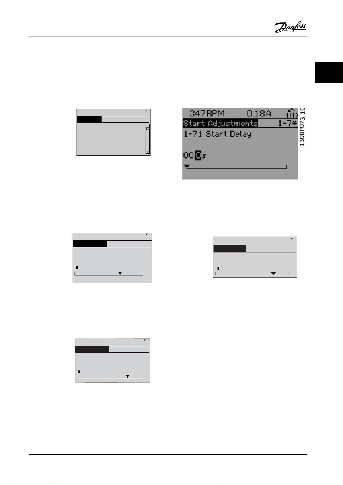
1-71 High starting torque time
0. s
11.58A 1 (1)
1-7*Start Adjustments
4
How to Program Programming Guide
2.1.11 Changing a Text Value
If the selected parameter is a text value, change the text
value with the [▲] [▼] keys.
Place the cursor on the value to save and press [OK].
Figure 2.16 Changing a Text Value
2.1.12 Changing a Data Value
If the selected parameter shows a numeric data value,
change the selected data value with the [◀] [▶] navigation
keys and the [▲] [▼] navigation keys. Press [◀] [▶] keys to
move the cursor horizontally.
2.1.13 Innitely Variable Change of
Numeric Data Value
If the selected parameter shows a numeric data value,
select a digit with [◀] [▶].
Figure 2.19 Selecting a Digit
Change the selected digit innitely variably with [▲] [▼].
The cursor indicates the selected digit. Place the cursor on
the digit to save and press [OK].
2 2
Figure 2.17 Changing a Data Value
Figure 2.20 Saving
2.1.14 Value, Step by Step
Press [▲] [▼] keys to change the data value. [▲] increases
the data value, and [▼] decreases the data value. Place the
cursor on the value to save and press [OK].
Figure 2.18 Saving a Data Value
MG33MO22 Danfoss A/S © 01/2018 All rights reserved. 21
Certain parameters can be changed step by step. This
applies to:
Parameter 1-20 Motor Power [kW].
•
Parameter 1-22 Motor Voltage.
•
Parameter 1-23 Motor Frequency.
•
The parameters are changed both as a group of numeric
data values and as numeric data values that are
innitely
varying.
Page 24
130BA191.10
1
Auto
on
Reset
Hand
on
O
Menu
Status
Quick
Setup
Main
Menu
Back
2
3
4
OK
On
Alarm
Warn.
Setup
130BP077.10
22.8
rpm
Setup 1
How to Program
VLT® AutomationDrive FC 301/302
2.1.15 Readout and Programming of
22
Parameters are indexed when placed in a rolling stack.
Parameter 15-30 Fault Log: Error Code to
parameter 15-32 Alarm Log: Time contain a fault log, which
can be read out. Select a parameter, press [OK], and press
the keys [▲] [▼] to scroll through the value log.
For example, parameter 3-10 Preset Reference is changed as
follows:
Indexed Parameters
1.
Select the parameter, press [OK], and press [▲] [▼]
to scroll through the indexed values.
2. To change the parameter value, select the
indexed value and press [OK].
3.
Change the value by pressing [▲] [▼].
4. Press [OK] to accept the new setting.
5. Press [Cancel] to abort. Press [Back] to leave the
parameter.
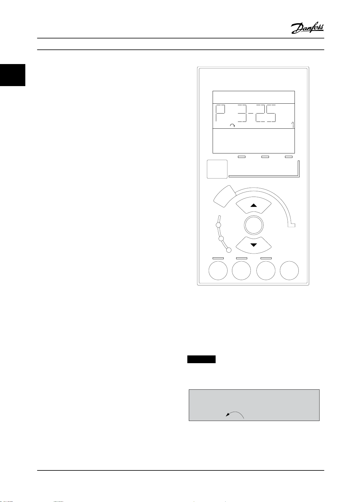
2.1.16 How to Program on the Numerical
Local Control Panel
The following instructions are valid for the numerical LCP
(LCP 101).
The control panel is divided into 4 functional groups:
Numerical display.
•
Menu keys and indicator lights - changing
•
parameters and switching between display
functions.
Navigation keys and indicator lights.
•
Operation keys and indicator lights.
•
Display line
Status messages showing icons and numeric value.
Indicator lights
Green LED/On: Indicates if control section is on.
•
Yellow LED/Wrn: Indicates a warning.
•
Flashing red LED/Alarm: Indicates an alarm.
•
LCP keys
[Menu]
Select 1 of the following modes:
•
•
•
Status.
Quick set-up.
Main menu.
Figure 2.21 LCP Keys
Status mode
Status mode shows the status of the frequency converter
or the motor.
If an alarm occurs, the NLCP automatically switches to
status mode.
Several alarms can be shown.
NOTICE!
Parameter copy is not possible with LCP 101 numerical
local control panel.
Figure 2.22 Status Mode
22 Danfoss A/S © 01/2018 All rights reserved. MG33MO22
Page 25
Setup 1
130BP078.10
A 17
130BP046.10
Hand
on
O
Auto
on
Reset
How to Program Programming Guide
Figure 2.23 Alarm
Main Menu/Quick Set-up
Are used for programming all parameters or only the
parameters in the Quick Menu (see also description of the
LCP 102 in chapter 2.1 Graphical and Numerical Local
Control Panels).
When the value ashes, press [▲] or [▼] to change
parameter values.
1. Press [Main Menu] to select main menu.
2. Select the parameter group [xx-__] and press
[OK].
3. Select the parameter [__-xx] and press [OK].
4. If the parameter is an array parameter, select the
array number and press [OK].
5. Select the required data value and press [OK].
Parameters with functional options show values such as
[1], [2], and so on. For a description of the dierent
options, see the individual parameter descriptions in
chapter 3 Parameter Descriptions.
[Back]
Used for stepping backwards.
[▲] [▼] are used for maneuvering between commands and
within parameters.
2.1.17 LCP Keys
Keys for local control are at the bottom of the LCP.
Figure 2.25 LCP Keys
[Hand On]
Enables control of the frequency converter via the LCP.
[Hand On] also starts the motor and it is now possible to
enter the motor speed data with the navigation keys. The
key can be selected as [1] Enable or [0] Disable via
parameter 0-40 [Hand on] Key on LCP.
External stop signals activated with control signals, or a
eldbus, override a start command via the LCP.
The following control signals are still active when [Hand
On] is activated:
[Hand On] - [O] - [Auto On].
•
Reset.
•
Coast stop inverse.
•
Reversing.
•
Set-up select lsb - Set-up select msb.
•
Stop command from serial communication.
•
Quick stop.
•
DC brake.
•
[O]
Stops the connected motor. The key can be selected as [1]
Enable or [0] Disable via parameter 0-41 [O] Key on LCP.
If no external stop function is selected and the [O] key is
inactive, stop the motor by disconnecting the voltage.
2 2
Figure 2.24 Main Menu/Quick Set-up
MG33MO22 Danfoss A/S © 01/2018 All rights reserved. 23
Page 26

How to Program
VLT® AutomationDrive FC 301/302
[Auto On]
22
Enables control of the frequency converter via the control
terminals and/or serial communication. When a start signal
is applied on the control terminals and/or the bus, the
frequency converter starts. The key can be selected as [1]
Enable or [0] Disable via parameter 0-42 [Auto on] Key on
LCP.
NOTICE!
An active HAND-OFF-AUTO signal via the digital inputs
has higher priority than the control keys [Hand On] and
[Auto On].
[Reset]
Is used for resetting the frequency converter after an alarm
(trip). It can be selected as [1] Enable or [0] Disable via
parameter 0-43 [Reset] Key on LCP.
2.1.18 Initialization to Default Settings
Manual initialization
1. Disconnect from mains and wait until the display
turns o.
2. 2a Press [Status] - [Main Menu] - [OK] at
the same time while powering up the
LCP 102, graphical display.
2b Press [Menu] - [OK] while powering up
the LCP 101, numerical display.
3. Release the keys after 5 s.
4. The frequency converter is now programmed
according to default settings.
This procedure initializes all except:
Parameter 15-00 Operating hours.
•
Parameter 15-03 Power Up's.
•
Parameter 15-04 Over Temp's.
•
Parameter 15-05 Over Volt's.
•
NOTICE!
Initialize the frequency converter to default settings in 2
ways.
Recommended initialization (via
parameter 14-22 Operation Mode)
1. Select parameter 14-22 Operation Mode.
2. Press [OK].
3. Select [2] initialization.
4. Press [OK].
5. Disconnect the mains supply and wait until the
display turns o.
6. Reconnect the mains supply. The frequency
converter is now reset.
Parameter 14-22 Operation Mode initializes all except:
Parameter 14-50 RFI Filter.
•
Parameter 8-30 Protocol.
•
Parameter 8-31 Address.
•
Parameter 8-32 FC Port Baud Rate.
•
Parameter 8-35 Minimum Response Delay.
•
Parameter 8-36 Max Response Delay.
•
Parameter 8-37 Max Inter-Char Delay.
•
Parameter 15-00 Operating hours to
•
parameter 15-05 Over Volt's.
Parameter 15-20 Historic Log: Event to
•
parameter 15-22 Historic Log: Time.
Parameter 15-30 Fault Log: Error Code to
•
parameter 15-32 Alarm Log: Time.
A manual initialization also resets serial communication,
RFI lter settings (parameter 14-50 RFI Filter), and fault
log settings.
24 Danfoss A/S © 01/2018 All rights reserved. MG33MO22
Page 27
Parameter Descriptions Programming Guide
3 Parameter Descriptions
3.1 Parameters: 0-** Operation and Display
Parameters related to the fundamental functions of the
frequency converter, function of the LCP keys, and congu-
ration of the LCP display.
0-01 Language
Option: Function:
Denes display language. The frequency
converter is delivered with 4 dierent
language packages. English and German
are included in all packages. English
cannot be erased or manipulated.
[0] * English Part of language packages 1–4
[1] Deutsch Part of language packages 1–4
[2] Francais Part of language package 1
[3] Dansk Part of language package 1
[4] Spanish Part of language package 1
[5] Italiano Part of language package 1
[6] Svenska Part of language package 1
[7] Nederlands Part of language package 1
[10] Chinese Part of language package 2
[20] Suomi Part of language package 1
[22] English US Part of language package 4
0-01 Language
Option: Function:
[49] Russian Part of language package 3
[50] Thai Part of language package 2
[51] Bahasa
Indonesia
[52] Hrvatski Part of language package 3
[53] Arabic
Part of language package 2
0-02 Motor Speed Unit
Option: Function:
NOTICE!
This parameter cannot be adjusted while the
motor is running.
The information shown in the display depends on
settings in parameter 0-02 Motor Speed Unit and
parameter 0-03 Regional Settings. The default settings
of parameter 0-02 Motor Speed Unit and
parameter 0-03 Regional Settings depend on to which
region of the world the frequency converter is
supplied.
NOTICE!
Changing the motor speed unit resets certain
parameters to their initial value. Select the
motor speed unit before modifying other
parameters.
3 3
[27] Greek Part of language package 4
[28] Bras.port Part of language package 4
[36] Slovenian Part of language package 3
[39] Korean Part of language package 2
[40] Japanese Part of language package 2
[41] Turkish Part of language package 4
[42] Trad.Chinese Part of language package 2
[43] Bulgarian Part of language package 3
[44] Srpski Part of language package 3
[45] Romanian Part of language package 3
[46] Magyar Part of language package 3
[47] Czech Part of language package 3
[48] Polski Part of language package 4
MG33MO22 Danfoss A/S © 01/2018 All rights reserved. 25
[0] RPM Select to show motor speed variables and parameters
using motor speed (RPM).
[1] * Hz Select to show motor speed variables and parameters
using output frequency (Hz).
0-03 Regional Settings
Option: Function:
NOTICE!
This parameter cannot be adjusted while
the motor is running.
[0] * Interna-
tional
[1] US Activate parameter 1-20 Motor Power [kW] for
Activate parameter 1-20 Motor Power [kW] for
setting the motor power in kW and set the
default value of parameter 1-23 Motor Frequency
to 50 Hz.
setting the motor power in hp and set the
Page 28
Parameter Descriptions
VLT® AutomationDrive FC 301/302
0-03 Regional Settings
Option: Function:
default value of parameter 1-23 Motor Frequency
to 60 Hz.
33
0-04 Operating State at Power-up (Hand)
Option: Function:
Select the operating mode upon
reconnection of the frequency converter to
mains voltage after power down in hand-on
mode.
[0] Resume Restart the frequency converter, maintaining
the start/stop settings (applied by [Hand On/
O]) selected before the power-down of the
frequency converter.
[1] * Forced stop,
ref=old
[2] Forced stop,
ref=0
3.1.1 0-1* Set-up Operations
Dene and control the individual parameter set-ups.
The frequency converter has 4 parameter set-ups that can
be programmed independently of each other. This makes
the frequency converter very exible and able to solve
advanced control functionality problems, often saving the
cost of external control equipment. Parameter set-ups can
be used to program the frequency converter to operate
according to 1 control scheme in 1 set-up (for example
motor 1 for horizontal movement) and another control
scheme in another set-up (for example motor 2 for vertical
Restart the frequency converter with a saved
local reference after mains voltage reappears
and after pressing [Hand On].
Reset the local reference to 0 upon restarting
the frequency converter.
up to the one being edited. By using parameter 0-51 Set-up
Copy, it is possible to copy parameter settings between the
set-ups to enable quicker commissioning if similar
parameter settings are required in dierent set-ups.
0-10 Active Set-up
Option: Function:
Select the set-up to control the frequency
converter functions.
[0] Factory
setup
[1] * Set-up 1 [1] Set-up 1 to [4] Set-up 4 are the 4 separate
[2] Set-up 2
[3] Set-up 3
[4] Set-up 4
[9] Multi
setup
Cannot be changed. It contains the Danfoss
data set and can be used as a data source
when returning the other set-ups to a known
state.
parameter set-ups within which all parameters
can be programmed.
Remote set-up selections using digital inputs
and the serial communication port. This set-up
uses the settings from parameter 0-12 This Set-
up Linked to. Stop the frequency converter
before making changes to open and closedloop functions.
Use parameter 0-51 Set-up Copy to copy a set-up to 1 or all
other set-ups. Stop the frequency converter before
switching between set-ups where parameters marked not
changeable during operation have dierent values. To avoid
conicting settings of the same parameter within 2
dierent set-ups, link the set-ups together using
parameter 0-12 This Set-up Linked to. Parameters which are
not changeable during operation are marked FALSE in the
parameter lists in chapter 5 Parameter Lists.
movement). Alternatively, parameter set-ups can be used
by an OEM machine builder to identically program all their
factory-tted frequency converters for dierent machine
types within a range to have the same parameters. During
production/commissioning, simply select a specic set-up
depending on which machine the frequency converter is
installed on.
The active set-up (that is the set-up in which the frequency
converter is currently operating) can be selected in
parameter 0-10 Active Set-up and is shown in the LCP. By
using multi set-up, it is possible to switch between set-ups
with the frequency converter running, or it can be stopped
via digital input or serial communication commands. If it is
necessary to change set-ups while the frequency converter
is running, ensure that parameter 0-12 This Set-up Linked to
is programmed as required. By using parameter 0-11 Edit
Set-up, it is possible to edit parameters within any of the
0-11 Edit Set-up
Option: Function:
Select the set-up to be edited (that is
programmed) during operation; either the
active set-up or 1 of the inactive set-ups.
[0] Factory
setup
[1] * Set-up 1 [1] Set-up 1 to [4] Set-up 4 can be edited freely
[2] Set-up 2
[3] Set-up 3
[4] Set-up 4
Cannot be edited but it is useful as a data
source to return the other set-ups to a known
state.
during operation, independently of the active
set-up.
set-ups while continuing the operation of the frequency
converter in its active set-up, which can be a dierent set-
26 Danfoss A/S © 01/2018 All rights reserved. MG33MO22
Page 29
130BP075.10
130BP076.10
Parameter Descriptions Programming Guide
0-11 Edit Set-up
Option: Function:
[9] Active Set-upCan also be edited during operation. Edit the
selected set-up from a range of sources: LCP,
FC RS485, FC USB, or up to 5 eldbus sites.
0-12 This Set-up Linked to
Option: Function:
by the label FALSE in the parameter lists in
chapter 5 Parameter Lists.
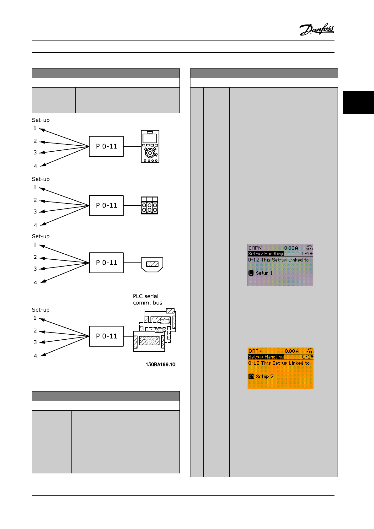
Parameter 0-12 This Set-up Linked to is used by
[9] Multi set-up in parameter 0-10 Active Set-up.
Multi set-up is used to move from 1 set-up to
another during operation (that is while the
motor runs).
Example:
Use multi set-up to shift from set-up 1 to set-up
2 while the motor runs. Program in set-up 1
rst, then ensure that set-up 1 and set-up 2 are
synchronized (or linked). Synchronization can be
performed in 2 ways:
1. Select the following options:
[2] Set-up 2 in parameter 0-11 Edit Set-
•
up.
parameter 0-12 This Set-up Linked to to
•
[1] Set-up 1.
This starts the linking (synchronizing) process.
3 3
Figure 3.1 Edit Set-up
0-12 This Set-up Linked to
Option: Function:
To enable conict-free changes from 1 set-up to
another during operation, link set-ups
containing parameters which are not changeable
during operation. The link ensures synchronizing
of the not changeable during operationparameter values when moving from 1 set-up
to another during operation. Not changeable
during operation-parameters can be identied
Figure 3.2 Set-up 1
OR
2. While still in set-up 1, copy set-up 1 to set-up
2. Then set parameter 0-12 This Set-up Linked to
to [2] Set-up 2. This starts the linking process.
Figure 3.3 Set-up 2
When completed, parameter 0-13 Readout:
Linked Set-ups reads {1,2} to indicate that all not
changeable during operation-parameters are now
the same in set-up 1 and set-up 2. If there are
changes to a not changeable during operationparameter, for example parameter 1-30 Stator
Resistance (Rs), in set-up 2, they are also
changed automatically in set-up 1. A switch
MG33MO22 Danfoss A/S © 01/2018 All rights reserved. 27
Page 30
Parameter Descriptions
VLT® AutomationDrive FC 301/302
0-12 This Set-up Linked to
Option: Function:
between set-up 1 and set-up 2 during
operation is now possible.
33
[0] * Not linked
[1] Set-up 1
[2] Set-up 2
[3] Set-up 3
[4] Set-up 4
0-15 Readout: actual setup
Range: Function:
0* [0 - 255] Makes it possible to read out the active set-up,
also when [9] Multi set-up is selected in
parameter 0-10 Active Set-up.
0-13 Readout: Linked Set-ups
Array [5]
Range: Function:
0* [0 -
255 ]
View a list of all the set-ups linked by
parameter 0-12 This Set-up Linked to. The parameter
has 1 index for each parameter set-up. The value
for each index shows which set-ups are linked to
that parameter set-up.
Index LCP value
0 {0}
1 {1,2}
2 {1,2}
3 {3}
4 {4}
Table 3.1 Set-up Link Example
0-14 Readout: Edit Set-ups / Channel
Range: Function:
0
[-2147483648 -
N/A*
2147483647
N/A]
View the setting of parameter 0-11 Edit
Set-up for each of the 4 dierent
communication channels. When the
number is shown as a hex number, as it
is in the LCP, each number represents 1
channel.
Numbers 1–4 represent a set-up number;
F means factory setting; and A means
active set-up. The channels are, from
right to left: LCP, FC bus, USB, HPFB1-5.
Example: The number AAAAAA21h
means the following:
The frequency converter
•
received the setting set-up 2
via a eldbus channel. This
selection is reected in
parameter 0-11 Edit Set-up.
A user selected set-up 1 via the
•
LCP.
All other channels are using the
•
active set-up.
28 Danfoss A/S © 01/2018 All rights reserved. MG33MO22
Page 31

Parameter Descriptions Programming Guide
3.1.2 0-2* LCP Display
Dene the variables shown in the LCP.
NOTICE!
For information on how to write display texts, refer to:
Parameter 0-37 Display Text 1.
•
Parameter 0-38 Display Text 2.
•
Parameter 0-39 Display Text 3.
•
0-20 Display Line 1.1 Small
Option: Function:
Select a variable for display in line
1, left position.
[0] None No display value selected.
[9] Performance
Monitor
[15] Readout: actual
setup
[37] Display Text 1
[38] Display Text 2
[39] Display Text 3
[953] Probus Warning
Word
[1005] Readout Transmit
Error Counter
[1006] Readout Receive
Error Counter
[1007] Readout Bus O
Counter
[1013] Warning Parameter
[1230] Warning Parameter
[1472] Legacy Alarm Word
[1473] Legacy Warning
Word
[1474] Leg. Ext. Status
Word
[1501] Running Hours
[1502] kWh Counter
[1580] Fan Running Hours
[1600] Control Word Present control word.
[1601] Reference [Unit] Total reference (sum of digital/
analog/preset/bus/freeze reference/
catch up and slow down) in
selected unit.
[1602] Reference % Total reference (sum of digital/
analog/preset/bus/freeze reference./
catch up and slow down) in
percent.
0-20 Display Line 1.1 Small
Option: Function:
[1603] Status Word Present status word.
[1605] Main Actual Value
[%]
[1606] Actual Position Actual position in position units
[1607] Target Position Active target position in position
[1608] Position Error Actual position PI error in position
[1609] Custom Readout
[1610] Power [kW] Actual power consumed by the
[1611] Power [hp] Actual power consumed by the
[1612] Motor Voltage Voltage supplied to the motor.
[1613] Frequency Motor frequency, that is the output
[1614] Motor current Phase current of the motor
[1615] Frequency [%] Motor frequency, that is the output
[1616] Torque [Nm] Actual motor torque in Nm.
[1617]*Speed [RPM] Speed in RPM (revolutions per
[1618] Motor Thermal Thermal load on the motor,
[1619] KTY sensor
temperature
[1620] Motor Angle
[1621] Torque [%] High
Res.
[1622] Torque [%] Present motor load as a percentage
[1623] Motor Shaft Power
[kW]
[1624] Calibrated Stator
Resistance
[1625] Torque [Nm] High
[1630] DC Link Voltage DC-link voltage in the frequency
Actual value as a percentage.
selected in parameter 17-70 Position
Unit.
units selected in
parameter 17-70 Position Unit.
units selected in
parameter 17-70 Position Unit.
motor in kW.
motor in hp.
frequency from the frequency
converter in Hz.
measured as eective value.
frequency from the frequency
converter in percent.
minute), that is the motor shaft
speed in closed loop.
calculated by the ETR function.
of the rated motor torque.
converter.
3 3
MG33MO22 Danfoss A/S © 01/2018 All rights reserved. 29
Page 32

Parameter Descriptions
VLT® AutomationDrive FC 301/302
0-20 Display Line 1.1 Small
Option: Function:
[1632] Brake Energy /s Present brake power transferred to
33
[1633] Brake Energy
Average
[1634] Heatsink Temp. Present heat sink temperature of
[1635] Inverter Thermal Percentage load of the inverters.
[1636] Inv. Nom. Current Nominal current of the frequency
[1637] Inv. Max. Current Maximum current of the frequency
[1638] SL Controller State State of the event executed by the
[1639] Control Card Temp. Temperature of the control card.
[1644] Speed Error [RPM]
[1645] Motor Phase U
Current
[1646] Motor Phase V
Current
[1647] Motor Phase W
Current
[1648] Speed Ref. After
Ramp [RPM]
[1650] External Reference Sum of the external reference as a
[1651] Pulse Reference Frequency in Hz connected to the
[1652] Feedback[Unit] Reference value from programmed
[1653] Digi Pot Reference
[1657] Feedback [RPM]
[1660] Digital Input Signal states from the 6 digital
an external brake resistor.
Stated as an instant value.
Brake power transferred to an
external brake resistor. The mean
power is calculated continuously for
the most recent 120 s.
the frequency converter. The cutout
limit is 95 ±5 °C (203 ±9 °F);
cutting back in occurs at 70 ±5 °C
(203 ±9 °F).
converter.
converter.
control.
percentage, that is the sum of
analog/pulse/bus.
digital inputs (18, 19 or 32, 33).
digital inputs.
terminals (18, 19, 27, 29, 32, and
33). There are 16 bits in total, but
only 6 of them are used. Input 18
corresponds to the far left of the
used bits. Signal low = 0; Signal
high = 1.
0-20 Display Line 1.1 Small
Option: Function:
[1661] Terminal 53 Switch
Setting
[1662] Analog Input 53 Actual value at input 53 either as a
[1663] Terminal 54 Switch
Setting
[1664] Analog Input 54 Actual value at input 54 either as
[1665] Analog Output 42
[mA]
[1666] Digital Output [bin] Binary value of all digital outputs.
[1667] Freq. Input #29
[Hz]
[1668] Freq. Input #33
[Hz]
[1669] Pulse Output #27
[Hz]
[1670] Pulse Output #29
[Hz]
[1671] Relay Output [bin]
[1672] Counter A Application-dependent (for example
[1673] Counter B Application-dependent (for example
[1675] Analog In X30/11 Actual value at input X30/11 either
[1676] Analog In X30/12 Actual value at input X30/12 either
[1677] Analog Out X30/8
[mA]
[1678] Analog Out X45/1
[mA]
[1679] Analog Out X45/3
[mA]
[1680] Fieldbus CTW 1 Control word (CTW) received from
[1682] Fieldbus REF 1 Main reference value sent with
Setting of input terminal 54.
Current = 0; Voltage = 1.
reference or protection value.
Setting of input terminal 54.
Current = 0; Voltage = 1.
reference or protection value.
Actual value at output 42 in mA.
Use parameter 6-50 Terminal 42
Output to select the value to be
shown.
Actual value of the frequency
applied at terminal 29 as an
impulse input.
Actual value of the frequency
applied at terminal 33 as an
impulse input.
Actual value of impulses applied to
terminal 27 in digital output mode.
Actual value of impulses applied to
terminal 29 in digital output mode.
SLC control).
SLC control).
as reference or protection value.
as reference or protection value.
Actual value at output X30/8 in mA.
Use parameter 6-60 Terminal X30/8
Output to select the value to be
shown.
the bus master.
control word from the bus master.
30 Danfoss A/S © 01/2018 All rights reserved. MG33MO22
Page 33

Parameter Descriptions Programming Guide
0-20 Display Line 1.1 Small
Option: Function:
[1684] Comm. Option
STW
[1685] FC Port CTW 1 Control word (CTW) received from
[1686] FC Port REF 1 Status word (STW) sent to the bus
[1687] Bus Readout
Alarm/Warning
[1689] Congurable
Alarm/Warning
Word
[1690] Alarm Word 1 or more alarms in a hex code.
[1691] Alarm Word 2 1 or more alarms in a hex code.
[1692] Warning Word 1 or more warnings in a hex code.
[1693] Warning Word 2 1 or more warnings in a hex code.
[1694] Ext. Status Word 1 or more status conditions in a
[1836] Analog Input X48/2
[mA]
[1837] Temp. Input X48/4
[1838] Temp. Input X48/7
[1839] Temp. Input
X48/10
[1860] Digital Input 2
[3110] Bypass Status Word
[3111] Bypass Running
Hours
[4235] S-CRC Value
[4282] Safe Control Word
[4283] Safe Status Word
[4285] Active Safe Func.
[4286] Safe Option Info
[9913] Idle time
[9914] Paramdb requests
in queue
[9917] tCon1 time
[9918] tCon2 time
[9919] Time Optimize
Measure
[9920] HS Temp. (PC1)
[9921] HS Temp. (PC2)
[9922] HS Temp. (PC3)
[9923] HS Temp. (PC4)
[9924] HS Temp. (PC5)
[9925] HS Temp. (PC6)
[9926] HS Temp. (PC7)
[9927] HS Temp. (PC8)
[9951] PC Debug 0
Extended eldbus communication
option status word.
the bus master.
master.
hex code.
0-20 Display Line 1.1 Small
Option: Function:
[9952] PC Debug 1
[9953] PC Debug 2
[9954] PC Debug 3
[9955] PC Debug 4
[9956] Fan 1 Feedback
[9957] Fan 2 Feedback
[9958] PC Auxiliary Temp
[9959] Power Card Temp.
0-21 Display Line 1.2 Small
Select a variable for display in line 1, middle position. The
options are the same as those listed for parameter 0-20 Display
Line 1.1 Small.
0-22 Display Line 1.3 Small
Select a variable for display in line 1, right position. The options
are the same as those listed for parameter 0-20 Display Line 1.1
Small.
0-23 Display Line 2 Large
Select a variable for display in line 2. The options are the same
as listed for parameter 0-20 Display Line 1.1 Small.
0-24 Display Line 3 Large
Select a variable for display in line 3.
0-25 My Personal Menu
Range: Function:
0
N/A
*
[0 9999
N/A]
Dene up to 50 parameters to appear in the Q1
Personal Menu, accessible via the [Quick Menu]
key on the LCP. The parameters are shown in the
Q1 Personal Menu in the order they are
programmed into this array parameter. Delete
parameters by setting the value to 0000.
For example, this can be used to provide quick,
simple access to just 1 or up to 50 parameters,
which require changing on a regular basis (for
example, for plant maintenance reasons) or by an
OEM to enable simple commissioning of their
equipment.
3.1.3 0-3* LCP Custom Readout
It is possible to customize the display elements for various
purposes:
Custom readout. Value proportional to speed
•
(linear, squared, or cubed depending on unit
selected in parameter 0-30 Custom Readout Unit).
Display text. Text string stored in a parameter.
•
3 3
MG33MO22 Danfoss A/S © 01/2018 All rights reserved. 31
Page 34

Custom Readout (Value)
P 16-09
Custom Readout
Unit P 0-30
Max value
P 0-32
Min value
P 0-31
Linear
units only
Quadratic Unit (Pressure)
Cubic Unit (Power)
Motor Speed
Motor Speed
High limit
P 4-13 (RPM)
P 4-14 (Hz)
0
130BT105.12
Linear Unit (e.g. speed and ow)
Parameter Descriptions
VLT® AutomationDrive FC 301/302
The calculated value to be shown is based on the settings
in:
33
The relation depends on the type of unit selected in
parameter 0-30 Custom Readout Unit:
Custom readout
Parameter 0-30 Custom Readout Unit.
•
Parameter 0-31 Custom Readout Min Value (linear
•
only).
Parameter 0-32 Custom Readout Max Value.
•
Parameter 4-13 Motor Speed High Limit [RPM].
•
Parameter 4-14 Motor Speed High Limit [Hz].
•
Actual speed.
•
Figure 3.4 Custom Readout
Unit type Speed relation
Dimensionless
Speed
Flow, volume
Flow, mass
Velocity
Length
Temperature
Pressure Quadratic
Power Cubic
Table 3.2 Speed Relations for Dierent Unit Types
Linear
0-30 Unit for User-dened Readout
Option: Function:
It is possible to program a value to be
shown in the display of the LCP. The value
has a linear, squared, or cubed relation to
speed. This relation depends on the unit
selected (see Table 3.2). The actual calculated
0-30 Unit for User-dened Readout
Option: Function:
value can be read in parameter 16-09 Custom
Readout, and/or shown in the display by
selecting [16-09] Custom Readout in
parameter 0-20 Display Line 1.1 Small to
parameter 0-24 Display Line 3 Large.
[0] * None
[1] %
[5] PPM
[10] min
[11] RPM
[12] PULSE/s
[20] liter / sec.
[21] liter / min
[22] liter / hr.
[23] m³ / sec.
[24] m³/min
[25] m³ / hr.
[30] kg / sec.
[31] kg/min
[32] kg / hr.
[33] ton / min
[34] ton / hr.
[40] m / sec.
[41] m/min
[45] m
[60] °C
[70] mbar
[71] bar
[72] Pa
[73] kPa
[74] m WG
[80] kW
[120] GPM
[121] gal / sec.
[122] gal/min
[123] gal / hr.
[124] CFM
[125] ft³/s
[126] ft³/min
[127] ft³/h
[130] lbs / sec.
[131] lbs / min.
[132] lbs / hr.
[140] ft/s
[141] ft/min
[145] ft
[160] °F
[170] psi
[171] lb/in²
32 Danfoss A/S © 01/2018 All rights reserved. MG33MO22
Page 35

Parameter Descriptions Programming Guide
0-30 Unit for User-dened Readout
Option: Function:
[172] in. wtr. gage
[173] ft WG
[180] HP
0-31 Min Value of User-dened Readout
Range: Function:
0.00 CustomReadoutUnit*
[-999999.99 par. 0-32
CustomReadoutUnit]
This parameter sets the
minimum value of the custom-
dened readout (occurs at 0
speed). Only possible to set
dierent from 0 when selecting
a linear unit in
parameter 0-30 Unit for Userdened Readout. For quadratic
and cubic units, the minimum
value is 0.
0-32 Custom Readout Max Value
Range: Function:
100 CustomReadoutUnit*
[ par. 0-31 -
999999.99
CustomReadoutUnit]
This parameter sets the
maximum value to be shown
when the speed of the motor
has reached the set value for
parameter 4-13 Motor Speed High
Limit [RPM] or
parameter 4-14 Motor Speed High
Limit [Hz] (depends on setting in
parameter 0-02 Motor Speed
Unit).
0-33 Source for User-dened Readout
Option: Function:
Enter the source of the user-dened
readout.
[105] Torq relate to rated
[240] * Default Source
0-37 Display Text 1
Range: Function:
0* [0 -
25]
Enter a text which can be viewed in the graphical
display by selecting [37] Display Text 1 in
Parameter 0-20 Display Line 1.1 Small,
•
Parameter 0-21 Display Line 1.2 Small,
•
Parameter 0-22 Display Line 1.3 Small,
•
Parameter 0-23 Display Line 2 Large, or
•
Parameter 0-24 Display Line 3 Large.
•
0-38 Display Text 2
Range: Function:
0* [0 -
25]
Enter a text which can be viewed in the graphical
display by selecting [38] Display Text 2 in
Parameter 0-20 Display Line 1.1 Small,
•
Parameter 0-21 Display Line 1.2 Small,
•
Parameter 0-22 Display Line 1.3 Small,
•
Parameter 0-23 Display Line 2 Large, or
•
Parameter 0-24 Display Line 3 Large.
•
0-39 Display Text 3
Range: Function:
0* [0 -
25]
Enter a text which can be viewed in the graphical
display by selecting [39] Display Text 3 in
Parameter 0-20 Display Line 1.1 Small,
•
Parameter 0-21 Display Line 1.2 Small,
•
Parameter 0-22 Display Line 1.3 Small,
•
Parameter 0-23 Display Line 2 Large, or
•
Parameter 0-24 Display Line 3 Large.
•
3.1.4 0-4* LCP Keypad
Enable, disable, and password protect individual keys on
the LCP.
0-40 [Hand on] Key on LCP
Option: Function:
[0] Disabled No eect when [Hand On] is pressed. Select [0]
Disabled to avoid accidental start of the
frequency converter in hand-on mode.
[1] * Enabled The LCP switches to hand-on mode directly
when [Hand On] is pressed.
[2] Password After pressing [Hand On] a password is required.
If parameter 0-40 [Hand on] Key on LCP is
included in My Personal Menu, dene the
password in parameter 0-65 Quick Menu
Password. Otherwise dene the password in
parameter 0-60 Main Menu Password.
0-41 [O] Key on LCP
Option: Function:
[0] Disabled Avoids accidental stop of the frequency
converter.
[1] * Enabled
[2] Password Avoids unauthorized stop. If parameter 0-41 [O]
Key on LCP is included in the Quick Menu, then
dene the password in parameter 0-65 Quick
Menu Password.
3 3
MG33MO22 Danfoss A/S © 01/2018 All rights reserved. 33
Page 36

Parameter Descriptions
VLT® AutomationDrive FC 301/302
0-42 [Auto on] Key on LCP
3.1.5 0-5* Copy/Save
Option: Function:
[0] Disabled Avoids accidental start of the frequency
converter in auto-on mode.
33
[1] * Enabled
[2] Password Avoids unauthorized start in auto-on mode. If
parameter 0-42 [Auto on] Key on LCP is included
in the Quick Menu, then dene the password in
parameter 0-65 Quick Menu Password.
0-43 [Reset] Key on LCP
Option: Function:
[0] Disabled No eect when [Reset] is pressed. Avoids
accidental alarm reset.
[1] * Enabled
[2] Password Avoids unauthorized resetting. If
parameter 0-43 [Reset] Key on LCP is included in
the Quick Menu, then dene the password in
parameter 0-65 Quick Menu Password.
0-44 [O/Reset] Key on LCP
Enable or disable the [O/Reset] key.
Option: Function:
[0] Disabled
[1] * Enabled
[2] Password
0-45 [Drive Bypass] Key on LCP
Press [O] and select [0] Disabled to avoid unintended stop of
the frequency converter. Press [O] and select [2] Password to
avoid unauthorized bypass of the frequency converter. If
parameter 0-45 [Drive Bypass] Key on LCP is included in the Quick
Menu, dene the password in parameter 0-65 Personal Menu
Password.
Option: Function:
[0] Disabled Select to disable the
key.
[1] * Enabled
[2] Password
Copy parameters from and to the LCP. Use these
parameters for saving and copying set-ups from 1
frequency converter to another.
0-50 LCP Copy
Option: Function:
NOTICE!
This parameter cannot be adjusted
while the motor is running.
[0] * No copy
[1] All to LCP Copies all parameters in all set-ups from
the frequency converter memory to the
LCP memory.
[2] All from LCP Copies all parameters in all set-ups from
the LCP memory to the frequency
converter memory.
[3] Size indep. of
LCP
[4] File from MCO
to LCP
[5] File from LCP
to MCO
0-51 Set-up Copy
Option: Function:
[0]*No copy No function.
[1] Copy to
set-up 1
[2] Copy to
set-up 2
[3] Copy to
set-up 3
[4] Copy to
set-up 4
[9] Copy to
all
Copy only the parameters that are
independent of the motor size. The latter
selection can be used to program several
frequency converters with the same
function without disturbing motor data.
Copies all parameters in the present
programming set-up (dened in
parameter 0-11 Programming Set-up) to set-up 1.
Copies all parameters in the present
programming set-up (dened in
parameter 0-11 Programming Set-up) to set-up 2.
Copies all parameters in the present
programming set-up (dened in
parameter 0-11 Programming Set-up) to set-up 3.
Copies all parameters in the present
programming set-up (dened in
parameter 0-11 Programming Set-up) to set-up 4.
Copies the parameters in the present set-up to
each of the set-ups 1 to 4.
34 Danfoss A/S © 01/2018 All rights reserved. MG33MO22
Page 37

Parameter Descriptions Programming Guide
3.1.6 0-6* Password
0-60 Main Menu Password
Range: Function:
100* [-9999 -
9999 ]
0-61 Access to Main Menu w/o Password
Option: Function:
[0] * Full
access
[1] Read-only Prevent unauthorized editing of Main Menu
[2] No access Prevent unauthorized viewing and editing of
[3] Read-only functions for parameters on eldbus
[4] No access to parameters is allowed via eldbus
[5] Read-only function for parameters on LCP,
[6] No access from LCP, eldbus, or FC standard
Dene the password for access to the Main
Menu via the [Main Menu] key. If
parameter 0-61 Access to Main Menu w/o
Password is set to [0] Full access, this
parameter is ignored.
Disables password dened in
parameter 0-60 Main Menu Password.
parameters.
Main Menu parameters.
and/or FC standard bus.
and/or FC standard bus.
eldbus, or FC standard bus.
bus is allowed.
0-66 Access to Quick Menu w/o Password
If parameter 0-61 Access to Main Menu w/o Password is set to [0]
Full access, then this parameter is ignored.
Option: Function:
[1] Read-only Prevents unauthorized editing of Quick Menu
parameters.
[2] No access
[3] Read-only functions for Quick Menu parameters
on eldbus and/or FC standard bus.
[4]
[5] Read-only function for Quick Menu parameters
on LCP, eldbus, or frequency converter
standard bus.
[6]
0-67 Bus Password Access
Range: Function:
0 N/A* [0 - 9999 N/A] Use this parameter to unlock the
frequency converter via eldbus or MCT
10 Set-up Software.
0-68 Safety Parameters Password
Range: Function:
300* [0 - 9999] Enter the password for the safety parameters
access. If parameter 0-69 Password Protection of
Safety Parameters is set to [0] Disabled, this
parameter is ignored.
3 3
If [0] Full access is selected, parameter 0-60 Main Menu
Password, parameter 0-65 Personal Menu Password, and
parameter 0-66 Access to Personal Menu w/o Password are
ignored.
NOTICE!
A more complex password protection is available for
OEMs upon request.
0-65 Quick Menu Password
Range: Function:
200
N/A*
[0] * Full access Disables the password dened in
[-9999 9999 N/A]
Dene the password for access to the Quick
Menu via the [Quick Menu] key. If
parameter 0-66 Access to Quick Menu w/o
Password is set to [0] Full access, this
parameter is ignored.
0-66 Access to Quick Menu w/o Password
If parameter 0-61 Access to Main Menu w/o Password is set to [0]
Full access, then this parameter is ignored.
Option: Function:
parameter 0-65 Quick Menu Password.
0-69 Password Protection of Safety Parameters
Option: Function:
[0] * Disabled
[1] Enabled
0-70 Date and Time
Range: Function:
Size
related*
[ 0 - 0 ] Sets the date and time of the internal
clock. The format to be used is set in
parameter 0-71 Date Format and
parameter 0-72 Time Format.
0-73 Time Zone Oset
Range: Function:
0 min* [-780 - 780
min]
Enter the time zone oset relative to
UTC. This parameter is required for the
automatic daylight saving time
adjustment.
MG33MO22 Danfoss A/S © 01/2018 All rights reserved. 35
Page 38
Parameter Descriptions
VLT® AutomationDrive FC 301/302
0-74 DST/Summertime
Option: Function:
Select how to handle daylight saving time/
33
[0] * O
[2] Manual
summertime. For manual setting of DST/
summertime, enter the start date and end date in
parameter 0-76 DST/Summertime Start and
parameter 0-77 DST/Summertime End.
0-82 Additional Working Days
Array [5]
Array with 5 elements [0]–[4] shown below the parameter
number in the display. Press [OK] and step between elements
with [▲] and [▼].
Range: Function:
Size related* [ 0 - 0 ] Denes dates for additional working days
that would normally be non-working
days according to parameter 0-81 Working
Days.
0-76 DST/Summertime Start
Range: Function:
Size
related*
[ 0 - 0 ] Sets the date and time when DST/
summertime starts. The date is
programmed in the format selected in
parameter 0-71 Date Format.
0-77 DST/Summertime End
Range: Function:
Size
related*
[ 0 - 0 ] Sets the date and time when DST/
summertime ends. The date is
programmed in the format selected in
parameter 0-71 Date Format.
0-79 Clock Fault
Option: Function:
Enables or disables the clock warning when the
clock has not been set, or has been reset due to a
power-down and no back-up is installed. If VLT
Analog I/O Option MCB 109 is installed, [1] Enabled
is default.
[0] Disabled
[1] Enabled
®
0-83 Additional Non-Working Days
Array [15]
Array with 15 elements [0]–[14] shown below the parameter
number in the display. Press [OK] and step between elements
with [▲] and [▼].
Range: Function:
Size related* [ 0 - 0 ] Denes dates for additional working days
that would normally be non-working
days according to parameter 0-81 Working
Days.
0-84 Time for Fieldbus
Range: Function:
0* [0 - 4294967295] Shows the time for eldbus.
0-85 Summer Time Start for Fieldbus
Range: Function:
0* [0 - 4294967295] Shows the summer time start for eldbus.
0-86 Summer Time End for Fieldbus
Range: Function:
0* [0 - 4294967295] Shows the summer time end for eldbus.
0-81 Working Days
Array [7]
Array with 7 elements [0]–[6] shown below the parameter
number in the display. Press [OK] and step between elements
with [▲] and [▼].
Option: Function:
Set for each weekday if it is a working day or a nonworking day. First element of the array is Monday. The
working days are used for timed actions.
[0] No
[1] Yes
0-89 Date and Time Readout
Range: Function:
0* [0 - 25 ] Shows the current date and time. The date and
time is updated continuously.
The clock does not begin counting until a setting
dierent from default has been made in
parameter 0-70 Date and Time.
36 Danfoss A/S © 01/2018 All rights reserved. MG33MO22
Page 39

Parameter Descriptions Programming Guide
3.2 Parameters: 1-** Load and Motor
3.2.1 1-0* General Settings
Dene whether the frequency converter operates in speed
mode or torque mode, and whether the internal PID
control should be active or not.
1-00 Conguration Mode
Option: Function:
Select the application control principle to be
used when a remote reference (that is via
analog input or eldbus) is active. A remote
reference can only be active when
parameter 3-13 Reference Site is set to [0]
Linked to Hand/Auto or [1] Remote.
[0] Speed open
loop
[1] Speed
closed loop
[2] Torque Enables torque closed-loop control with
Enables speed control (without feedback
signal from motor) with automatic slip
compensation for almost constant speed at
varying loads.
Compensations are active, but can be
disabled in parameter group 1-0* Load/Motor.
Set the speed control parameters in
parameter group 7-0* Speed PID Ctrl.
Enables speed closed-loop control with
feedback. Obtain full holding torque at 0
RPM.
For increased speed accuracy, provide a
feedback signal and set the speed PID
control. Set the speed control parameters in
parameter group 7-0* Speed PID Ctrl.
feedback. Only possible with Flux with motor
feedback option, parameter 1-01 Motor Control
Principle.
1-00 Conguration Mode
Option: Function:
[6] Surface
Winder
[7] Extended
PID Speed
OL
[8] Extended
PID Speed
CL
[9] Positioning
Enables the surface winder control specic
parameters in parameter groups 7-2* Process
Ctrl. Feedb. and 7-3* Process PID Ctrl.
Specic parameters in parameter groups 7-2*
Process Ctrl. Feedb. to 7-5* Ext. Process PID Ctrl.
Specic parameters in parameter groups 7-2*
Process Ctrl. Feedb. to 7-5* Ext. Process PID Ctrl.
NOTICE!
This option is available only with
software version 48.XX.
Activates the positioning mode.
[10] Synchroni-
zation
NOTICE!
This option is available only with
software version 48.XX.
Activates the synchronization mode.
3 3
NOTICE!
This is valid for FC 302 only.
[3] Process Enables the use of process control in the
frequency converter. Set the process control
parameters in parameter groups 7-2* Process
Ctrl. Feedb. and 7-3* Process PID Ctrl.
[4] Torque open
loop
[5] Wobble Enables the wobble functionality in
MG33MO22 Danfoss A/S © 01/2018 All rights reserved. 37
Enables the use of torque open loop in VVC
mode (parameter 1-01 Motor Control Principle).
Set the torque PID parameters in parameter
group 7-1* Torque PI Control.
parameter 30-00 Wobble Mode to
parameter 30-19 Wobble Delta Freq. Scaled.
+
Page 40

Parameter Descriptions
VLT® AutomationDrive FC 301/302
1-01 Motor Control Principle
Option: Function:
NOTICE!
33
This parameter cannot be adjusted
while the motor is running.
1-02 Flux Motor Feedback Source
Option: Function:
[2] MCB 102 Encoder module option, which can be
congured in parameter group 17-1* Inc. Enc.
Interface.
NOTICE!
Select which motor control principle to
employ.
[0]*U/f Special motor mode, for parallel connected
motors in special motor applications. When
U/f is selected, the characteristic of the
control principle can be edited in
parameter 1-55 U/f Characteristic - U and
parameter 1-56 U/f Characteristic - F.
[1] VVC+ Voltage vector control principle is suitable for
most applications. The main benet of VVC
operation is that it uses a robust motor
model.
[2] Flux
sensorless
Flux vector control without encoder feedback,
for simple installation and robustness against
sudden load changes.
NOTICE!
This is valid for FC 302 only.
[3] MCB 103 Optional resolver interface module, which
[5] MCO
Encoder 2
[6]
+
[7]
[8]
[9]
1-03 Torque Characteristics
Option: Function:
This is valid for FC 302 only.
can be congured in parameter group 17-5*
Resolver Interface.
Encoder interface 2 of the optional VLT
Motion Control MCO 305.
NOTICE!
This parameter cannot be adjusted
while the motor is running.
®
[3] Flux w/
motor feedb
High accuracy speed and torque control,
suitable for the most demanding applications.
NOTICE!
This is valid for FC 302 only.
The best shaft performance is normally achieved using
either of the 2 ux vector control modes [2] Flux sensorless
and [3] Flux with encoder feedback.
1-02 Flux Motor Feedback Source
Option: Function:
NOTICE!
This parameter cannot be adjusted
while the motor is running.
Select the interface for which to receive
feedback from the motor.
[0] Motor feedb.
P1-02
[1] * 24V encoder A and B channel encoder, which can be
connected to the digital input terminals
32/33 only. Program Terminals 32/33 to No
operation.
Select the torque characteristic required.
VT and AEO are both energy-saving
operations.
[0]*Constant
torque
[1] Variable
torque
[2] Auto
Energy
Optim.
Motor shaft output provides constant torque
under variable speed control.
Motor shaft output provides variable torque
under variable speed control. Set the variable
torque level in parameter 14-40 VT Level.
Automatically optimizes energy consumption
by minimizing magnetization and frequency
via parameter 14-41 AEO Minimum Magneti-
sation and parameter 14-42 Minimum AEO
Frequency.
1-04 Overload Mode
Option: Function:
NOTICE!
This parameter cannot be adjusted while
the motor is running.
Use this parameter to congure the frequency
converter for either high or normal overload.
When selecting the frequency converter size,
always review the technical data in the
38 Danfoss A/S © 01/2018 All rights reserved. MG33MO22
Page 41

Parameter Descriptions Programming Guide
1-04 Overload Mode
Option: Function:
operating guide or the design guide to know the
available output current.
[0] * High
torque
[1] Normal
torque
Allows up to 160% over torque.
For oversized motor - allows up to 110% over
torque.
1-05 Local Mode Conguration
Option: Function:
Select which application conguration mode
(parameter 1-00 Conguration Mode), that is
application control principle, to use when a
local (LCP) reference is active. A local reference
can be active only when
parameter 3-13 Reference Site is set to [0] Linked
to Hand/Auto or [2] Local. By default the local
reference is active in hand-on mode only.
[0] Speed
open-loop
[1] Speed
closedloop
[2] * As mode
par 1-00
1-06 Clockwise Direction
Option: Function:
NOTICE!
This parameter cannot be adjusted while
the motor is running.
This parameter denes the term clockwise
corresponding to the LCP direction arrow. Used for
easy change of direction of shaft rotation without
swapping motor wires.
[0] * Normal The motor shaft turns in clockwise direction when
the frequency converter is connected U⇒U, V⇒V,
and W⇒W to the motor.
[1] Inverse Motor shaft turns in counterclockwise direction
when the frequency converter is connected U⇒U,
V⇒V, and W⇒W to the motor.
1-07 Motor Angle Oset Adjust
Range: Function:
NOTICE!
This parameter is only valid for FC 302
and only in combination with a PM motor
with feedback.
1-07 Motor Angle Oset Adjust
Range: Function:
0* [Manual] The functionality of this option depends on the
type of the feedback device. This option sets the
frequency converter to use the motor angle
oset entered in parameter 1-41 Motor Angle
Oset, if an absolute feedback device is used.
If an incremental feedback device is selected, the
frequency converter automatically adjusts the
motor angle oset on the rst start after powerup, or when the motor data is changed.
[1] Auto The frequency converter adjusts the motor angle
oset automatically on the rst start after powerup, or when the motor data is changed no
matter what feedback device is selected. This
means that options Manual and Auto are
identical for the incremental encoder.
[2] Auto
Every
Start
[3] O Selecting this option turns the automatic oset
[4] Once with
Store
The frequency converter adjusts the motor angle
oset automatically on every start, or when the
motor data is changed.
adjustment o.
This option updates parameter 1-41 Motor Angle
Oset automatically when the angle value is 0.
This option is valid only for absolute feedback
devices. The function uses rotor detection and
then applies DC hold to make the oset
adjustment more accurate.
3.2.2 1-1* Special Settings
NOTICE!
The parameters within this parameter group cannot be
adjusted while the motor is running.
3.2.3 Asynchronous Motor Set-up
Enter the following motor data. Find the information on
the motor nameplate.
1. Parameter 1-20 Motor Power [kW] or
parameter 1-21 Motor Power [HP].
2. Parameter 1-22 Motor Voltage.
3. Parameter 1-23 Motor Frequency.
4. Parameter 1-24 Motor Current.
5. Parameter 1-25 Motor Nominal Speed.
3 3
MG33MO22 Danfoss A/S © 01/2018 All rights reserved. 39
Page 42

Parameter Descriptions
VLT® AutomationDrive FC 301/302
When running in ux control principle, or for optimum
performance in VVC+ mode, extra motor data is required to
set up the following parameters. Find the data in the
motor datasheet (this data is typically not available on the
33
motor nameplate). Run a complete automatic motor
adaptation (AMA) using parameter 1-29 Automatic Motor
Adaptation (AMA) [1] Enable Complete AMA or enter the
parameters manually. Parameter 1-36 Iron Loss Resistance
(Rfe) is always entered manually.
1. Parameter 1-30 Stator Resistance (Rs).
2. Parameter 1-31 Rotor Resistance (Rr).
3. Parameter 1-33 Stator Leakage Reactance (X1).
4. Parameter 1-34 Rotor Leakage Reactance (X2).
5. Parameter 1-35 Main Reactance (Xh).
6. Parameter 1-36 Iron Loss Resistance (Rfe).
Application-specic adjustment when running VVC
+
Application Settings
Flux sensorless control
principle only
Table 3.3 Recommendations for Flux Applications
Adjust parameter 1-53 Model Shift
Frequency.
Example 1: If the motor oscillates at
5 Hz, and dynamics performance is
required at 15 Hz, set
parameter 1-53 Model Shift Frequency
to 10 Hz.
Example 2: If the application
involves dynamic load changes at
low speed, reduce
parameter 1-53 Model Shift Frequency.
Observe the motor behavior to
make sure that the model shift
frequency is not reduced too much.
Symptoms of inappropriate model
shift frequency are motor oscillations
or frequency converter tripping.
VVC+ is the most robust control mode. In most situations,
it provides optimum performance without further
adjustments. Run a complete AMA for best performance.
Application-specic adjustment when running ux
Flux control principle is the preferred control principle for
optimum shaft performance in dynamic applications.
3.2.4 PM Motor Set-up
NOTICE!
Valid for FC 302 only.
Perform an AMA since this control mode requires precise
motor data. Depending on the application, further
This section describes how to set up a PM motor.
adjustments may be required.
See Table 3.3 for application-related recommendations.
Application Settings
Low-inertia applications Keep calculated values.
High-inertia applications Parameter 1-66 Min. Current at Low
Speed.
Increase current to a value between
default and maximum depending on
the application.
Set ramp times matching the
application. Too fast ramp up causes
an overcurrent or overtorque. Too
fast ramp down causes an
overvoltage trip.
High load at low speed Parameter 1-66 Min. Current at Low
Speed.
Increase current to a value between
default and maximum depending on
the application.
No-load application Adjust parameter 1-18 Min. Current at
No Load to achieve smoother motor
operation by reducing torque ripple
and vibration.
Initial programming steps
To activate PM motor operation, select [1] PM, non-salient
SPM in parameter 1-10 Motor Construction.
Programming motor data
After selecting a PM motor, the PM motor-related
parameters in parameter groups 1-2* Motor Data, 1-3* Adv.
Motor Data, and 1-4* Adv. Motor Data II are active.
The necessary data is on the motor nameplate and on the
motor datasheet.
Program the following parameters in the order listed:
1. Parameter 1-24 Motor Current.
2. Parameter 1-25 Motor Nominal Speed.
3. Parameter 1-26 Motor Cont. Rated Torque.
4. Parameter 1-39 Motor Poles.
Run a complete AMA using parameter 1-29 Automatic
Motor Adaptation (AMA) [1] Enable Complete AMA.
If a complete AMA is not performed, congure the
following parameters manually:
1. Parameter 1-30 Stator Resistance (Rs)
Enter the line-to-common stator winding
resistance (Rs). If only line-line data is available,
40 Danfoss A/S © 01/2018 All rights reserved. MG33MO22
Page 43

Parameter Descriptions Programming Guide
divide the line-line value by 2 to get the linecommon value.
2. Parameter 1-37 d-axis Inductance (Ld)
Enter the line-to-common direct axis inductance
of the PM motor.
If only line-line data is available, divide the lineline value by 2 to get the line-common value.
3. Parameter 1-40 Back EMF at 1000 RPM.
Enter the line-to-line back EMF of the PM Motor
at 1000 RPM (RMS value). Back EMF is the voltage
generated by a PM motor when no frequency
converter is connected and the shaft is turned
externally. It is normally specied for nominal
motor speed or for 1000 RPM measured between
2 lines. If the value is not available for a motor
speed of 1000 RPM, calculate the correct value as
follows:
If back EMF is, for example, 320 V at 1800 RPM, it
can be calculated at 1000 RPM as follows:
Back EMF = (Voltage/RPM)x1000 =
(320/1800)x1000 = 178.
Test motor operation
1. Start the motor at low speed (100–200 RPM). If
the motor does not turn, check the installation,
general programming, and motor data.
2. Check if the start function in parameter 1-70 Start
Mode ts the application requirements.
Rotor detection
This function is the recommended selection for
applications where the motor starts from standstill, for
example pumps or conveyors. On some motors, a sound is
heard when the frequency converter performs the rotor
detection. This does not harm the motor.
Parking
This function is the recommended selection for
applications where the motor is rotating at slow speed, for
example windmilling in fan applications.
Parameter 2-06 Parking Current and parameter 2-07 Parking
Time can be adjusted. Increase the factory setting of these
parameters for applications with high inertia.
Application-specic adjustment when running VVC
+
VVC+ is the most robust control mode. In most situations,
it provides optimum performance without further
adjustments. Run a complete AMA for best performance.
Start the motor at nominal speed. If the application does
not run well, check the VVC+ PM settings. Table 3.4
contains recommendations for various applications.
Application Settings
Low-inertia applications
I
Load/IMotor
Low-inertia applications
50>I
High-inertia applications
I
Load/IMotor
High load at low speed
<30% (rated speed)
<5
Load/IMotor
Table 3.4 Recommendations for Various Applications
>5
>50
Increase parameter 1-17 Voltage lter
time const. by factor 5–10.
Reduce parameter 1-14 Damping
Gain.
Reduce parameter 1-66 Min. Current
at Low Speed (<100%).
Keep the default values.
Increase parameter 1-14 Damping
Gain, parameter 1-15 Low Speed Filter
Time Const., and parameter 1-16 High
Speed Filter Time Const.
Increase parameter 1-17 Voltage lter
time const.
Increase parameter 1-66 Min. Current
at Low Speed to adjust the starting
torque. 100% current provides
nominal torque as starting torque.
This parameter is independent of
parameter 30-20 High Starting Torque
Time [s] and parameter 30-21 High
Starting Torque Current [%]). Working
at a current level higher than 100%
for a prolonged time can cause the
motor to overheat.
If the motor starts oscillating at a certain speed, increase
parameter 1-14 Damping Gain. Increase the value in small
steps. Depending on the motor, this parameter can be set
to 10–100% higher than the default value.
Application-specic adjustment when running ux
Flux control principle is the preferred control principle for
optimum shaft performance in dynamic applications.
Perform an AMA because this control mode requires
precise motor data. Depending on the application, further
adjustments may be required.
See chapter 3.2.3 Asynchronous Motor Set-up for application-
specic recommendations.
3 3
MG33MO22 Danfoss A/S © 01/2018 All rights reserved. 41
Page 44
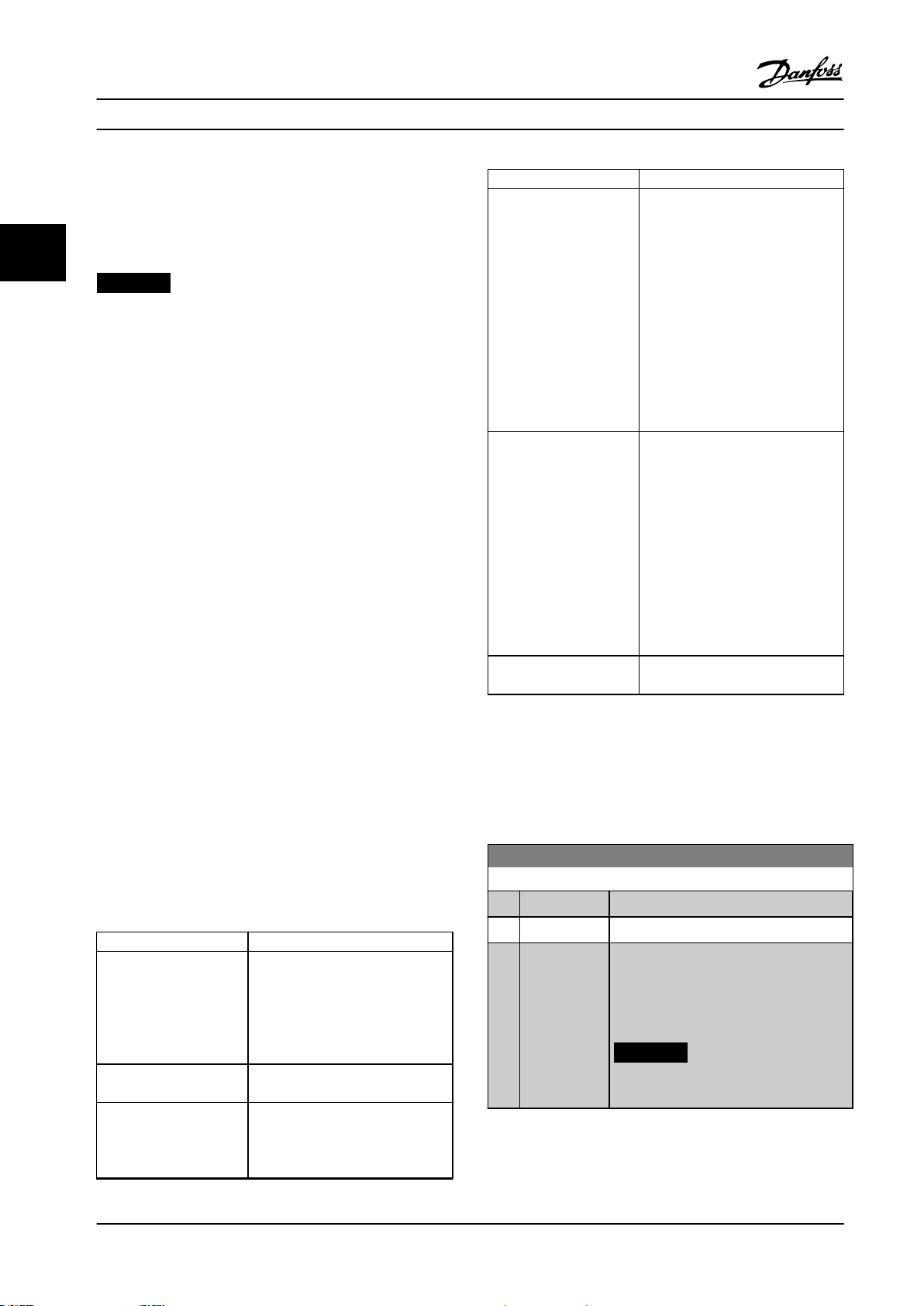
Parameter Descriptions
VLT® AutomationDrive FC 301/302
3.2.5
SynRM Motor Set-up with VVC
+
This section describes how to set up a SynRM motor with
VVC+.
33
NOTICE!
The SmartStart wizard covers the basic conguration of
SynRM motors.
Initial programming steps
To activate SynRM motor operation, select [5] Sync.
Reluctance in parameter 1-10 Motor Construction.
Programming motor data
After performing the initial programming steps, the SynRM
motor-related parameters in parameter groups 1-2* Motor
Data, 1-3* Adv. Motor Data, and 1-4* Adv. Motor Data II are
active.
Use the motor nameplate data and the motor datasheet to
program the following parameters in the order listed:
1. Parameter 1-23 Motor Frequency.
2. Parameter 1-24 Motor Current.
3. Parameter 1-25 Motor Nominal Speed.
4. Parameter 1-26 Motor Cont. Rated Torque.
Run a complete AMA using parameter 1-29 Automatic
Motor Adaptation (AMA) [1] Enable Complete AMA or enter
the following parameters manually:
1. Parameter 1-30 Stator Resistance (Rs).
2. Parameter 1-37 d-axis Inductance (Ld).
3. Parameter 1-44 d-axis Inductance Sat. (LdSat).
4. Parameter 1-45 q-axis Inductance Sat. (LqSat).
5. Parameter 1-48 Inductance Sat. Point.
Application-specic adjustments
Start the motor at nominal speed. If the application does
not run well, check the VVC+ SynRM settings. Table 3.5
provides application-specic recommendations:
Application Settings
Low-inertia applications
I
Load/IMotor
Low-inertia applications
50>I
High-inertia applications
I
Load/IMotor
<5
Load/IMotor
>50
>5
Increase parameter 1-17 Voltage lter
time const. by factor 5–10.
Reduce parameter 1-14 Damping
Gain.
Reduce parameter 1-66 Min. Current
at Low Speed (<100%).
Keep the default values.
Increase parameter 1-14 Damping
Gain, parameter 1-15 Low Speed Filter
Time Const., and parameter 1-16 High
Speed Filter Time Const.
Application Settings
High-load at low speed
<30% (rated speed)
Dynamic applications Increase parameter 14-41 AEO
Motor sizes less than
18 kW (24 hp)
Table 3.5 Recommendations for Various Applications
Increase parameter 1-17 Voltage lter
time const.
Increase parameter 1-66 Min. Current
at Low Speed to adjust the starting
torque. 100% current provides
nominal torque as starting torque.
This parameter is independent of
parameter 30-20 High Starting Torque
Time [s] and parameter 30-21 High
Starting Torque Current [%]). Working
at a current level higher than 100%
for a prolonged time can cause the
motor to overheat.
Minimum Magnetization for highly
dynamic applications. Adjusting
parameter 14-41 AEO Minimum
Magnetization ensures a good
balance between energy eciency
and dynamics. Adjust
parameter 14-42 Minimum AEO
Frequency to specify the minimum
frequency at which the frequency
converter should use minimum
magnetization.
Avoid short ramp-down times.
If the motor starts oscillating at a certain speed, increase
parameter 1-14 Damping Gain. Increase the damping gain
value in small steps. Depending on the motor, this
parameter can be set to 10–100% higher than the default
value.
1-10 Motor Construction
Option: Function:
Select the motor design type.
[0] * Asynchron Use for asynchronous motors.
[1] PM, non
salient SPM
Use for salient or non-salient PM motors.
PM motors are divided into 2 groups, with
either surface-mounted (SPM)/non-salient
magnets or interior-mounted (IPM)/salient
magnets.
NOTICE!
This option is valid for FC 302 only.
42 Danfoss A/S © 01/2018 All rights reserved. MG33MO22
Page 45

Parameter Descriptions Programming Guide
1-11 Motor Model
Option: Function:
Automatically sets the factory values for the
selected motor. If the default value Std.
Asynchron is used, determine settings
manually according to the selection
parameter 1-10 Motor Construction.
[1] Std.
Asynchron
[2] Std. PM, non
salient
[10] Danfoss OGD
LA10
[11] Danfoss OGD
V210
Default motor model when [0] Asynchron is
selected in parameter 1-10 Motor Construction.
Selectable when [1] PM, non-salient SPM is
selected in parameter 1-10 Motor Construction.
Selectable when [1] PM, non-salient SPM is
selected in parameter 1-10 Motor Construction.
Only available for T4, T5 in 1.5–3 kW. Settings
are loaded automatically for this specic
motor.
Selectable when [1] PM, non-salient SPM is
selected in parameter 1-10 Motor Construction.
Only available for T4, T5 in 0.75–3 kW.
Settings are loaded automatically for this
specic motor.
1-14 Damping Gain
Range: Function:
140%* [0 -
250 %]
The damping gain stabilizes the PM machine to
run smoothly and with stability. The value of
damping gain controls the dynamic performance
of the PM machine. High damping gain gives
high dynamic performance and low damping
gain gives low dynamic performance. The
dynamic performance is related to the machine
data and load type. If the damping gain is too
high or low, the control becomes unstable.
1-15 Low Speed Filter Time Const.
Range: Function:
Size related* [0.01 - 20s]This time constant is used below 10%
rated speed. Obtain quick control
through a short damping time
constant. However, if this value is too
short, the control becomes unstable.
1-16 High Speed Filter Time Const.
Range: Function:
Size related* [0.01 - 20s]This time constant is used above 10%
rated speed. Obtain quick control
through a short damping time
constant. However, if this value is too
short, the control becomes unstable.
1-17 Voltage lter time const.
Range: Function:
Size
related*
[0.001 - 1s]Reduces the inuence of high
frequency ripple and system resonance
in the calculation of supply voltage.
Without this lter, the ripples in the
currents can distort the calculated
voltage and aect the stability of the
system.
1-18 Min. Current at No Load
Range: Function:
0 %* [0 - 50 %] Adjust this parameter to achieve a smoother
motor operation.
3.2.6 1-2* Motor Data
This parameter group contains input data from the
nameplate on the connected motor.
NOTICE!
Changing the value of these parameters aects the
setting of other parameters.
NOTICE!
The following parameters have no eect when
parameter 1-10 Motor Construction is set to [1] PM, nonsalient SPM, [2] PM, salient IPM, [5] Sync. Reluctance:
Parameter 1-20 Motor Power [kW].
•
Parameter 1-21 Motor Power [HP].
•
Parameter 1-22 Motor Voltage.
•
Parameter 1-23 Motor Frequency.
•
1-20 Motor Power [kW]
Range: Function:
4.00
kW*
[0.09 -
3000.00
kW]
NOTICE!
This parameter cannot be adjusted
while the motor is running.
Enter the nominal motor power in kW
according to the motor nameplate data. The
default value corresponds to the nominal
rated output of the frequency converter.
This parameter is visible in the LCP if
parameter 0-03 Regional Settings is set to [0]
International.
3 3
MG33MO22 Danfoss A/S © 01/2018 All rights reserved. 43
Page 46

Parameter Descriptions
VLT® AutomationDrive FC 301/302
1-21 Motor Power [HP]
Range: Function:
4.00
[0.09 -
hp*
33
3000.00
hp]
Enter the nominal motor power in hp
according to the motor nameplate data. The
default value corresponds to the nominal
rated output of the unit. This parameter is
visible in the LCP if parameter 0-03 Regional
Settings is [1] US.
1-26 Motor Cont. Rated Torque
Range: Function:
0 Nm* [0.1 -
10000.0
Nm]
Enter the value from the motor nameplate
data. The default value corresponds to the
nominal rated output. This parameter is
available when parameter 1-10 Motor
Construction is set to [1] PM, non-salient SPM,
that is the parameter is valid for PM and
non-salient SPM motors only.
1-22 Motor Voltage
Range: Function:
500. V* [10. - 1000.V]Enter the nominal motor voltage
according to the motor nameplate data.
The default value corresponds to the
nominal rated output of the unit.
1-23 Motor Frequency
Range: Function:
50.
Hz*
[20 1000
Hz]
NOTICE!
From software version 6.72 onwards, the
output frequency of the frequency
converter is limited to 590 Hz.
Select the motor frequency value from the motor
nameplate data. If a value other than 50 Hz or 60
Hz is selected, adapt the load-independent
settings in parameter 1-50 Motor Magnetisation at
Zero Speed to parameter 1-53 Model Shift
Frequency. For 87 Hz operation with 230/400 V
motors, set the nameplate data for 230 V/50 Hz.
To run at 87 Hz, adapt parameter 4-13 Motor
Speed High Limit [RPM] and
parameter 3-03 Maximum Reference.
1-29 Automatic Motor Adaptation (AMA)
Option: Function:
NOTICE!
This parameter cannot be adjusted while
the motor is running.
The AMA function optimizes dynamic motor
performance by automatically optimizing the
advanced motor parameters
(parameter 1-30 Stator Resistance (Rs) to
parameter 1-35 Main Reactance (Xh)) at motor
standstill.
Activate the AMA function by pressing [Hand
on] after selecting Enable Complete AMA or [2]
Enable Reduced AMA. See also the section
Automatic Motor Adaptation in the design guide.
After a normal sequence, the display reads:
Press [OK] to
frequency converter is ready for operation.
nish AMA. After pressing [OK], the
NOTICE!
Ensure that a value is set in
parameter 14-43 Motor Cos-Phi before
running AMA II.
1-24 Motor Current
Range: Function:
7.20 A* [0.10 -
10000.00 A]
Enter the nominal motor current value
from the motor nameplate data. The
data is used for calculating torque,
motor overload protection, and so on.
1-25 Motor Nominal Speed
Range: Function:
1420.
RPM*
[10 - 60000
RPM]
Enter the nominal motor speed value
from the motor nameplate data. The
data is used for calculating motor
compensations. n
m,n
= ns - n
slip
.
[0]*O
[1] Enable
complete
AMA
Performs
AMA of the stator resistance RS,
•
The rotor resistance Rr,
•
The stator leakage reactance X1,
•
The rotor leakage reactance X2, and
•
The main reactance Xh.
•
Do not select this option if an LC lter is used
between the frequency converter and the
motor.
FC 301: The complete AMA does not include X
measurement for FC 301. Instead, the Xh value
is determined from the motor database. RS is
the best adjustment method (see parameter
group 1-3* Adv. Motor Data).
h
44 Danfoss A/S © 01/2018 All rights reserved. MG33MO22
Page 47

130BA065.12
P 1-30
R
Fe
X
h
R'
r
R
s
U
1
I
1
P 1-33
P 1-34
P 1-31P 1-35P 1-36
X'
2δ
X
1δ
Parameter Descriptions Programming Guide
1-29 Automatic Motor Adaptation (AMA)
Option: Function:
For best performance, it is recommended to
obtain the advanced motor data from the
motor manufacturer to enter into
parameter 1-31 Rotor Resistance (Rr) through
parameter 1-36 Iron Loss Resistance (Rfe).
Complete AMA cannot be performed on
permanent magnet motors.
[2] Enable
reduced
AMA
Performs a reduced AMA of the stator
resistance Rs in the system only. This option is
available for standard asynchronous motors and
non-salient PM motors.
NOTICE!
For the best adaptation of the frequency
•
converter, run AMA on a cold motor.
AMA cannot be performed while the motor is
•
running.
AMA cannot run with a sine-wave lter
•
connected.
3.2.7 1-3* Adv. Motor Data
Parameters for advanced motor data. Ensure that the
motor data in parameter 1-30 Stator Resistance (Rs) to
parameter 1-39 Motor Poles matches the motor. The default
settings are based on standard motor values. If the motor
parameters are not set correctly, a malfunction of the
frequency converter system may occur. If the motor data is
unknown, running an AMA (automatic motor adaptation) is
recommended. See parameter 1-29 Automatic Motor
Adaptation (AMA).
Parameter groups 1-3* Adv. Motor Data and 1-4* Adv. Motor
Data II cannot be adjusted while the motor is running.
NOTICE!
A simple check of the X1 + Xh sum value is to divide the
line-to-line motor voltage by the sqrt(3) and divide this
value by the motor no load current. [VL-L/sqrt(3)]/INL =
X1 + Xh, see Figure 3.6. These values are important to
magnetize the motor properly. For high-pole motors, it is
highly recommended to perform this check.
3 3
NOTICE!
It is important to set motor parameter group 1-2* Motor
Data correctly, since these form part of the AMA
algorithm. Perform an AMA to achieve optimum dynamic
motor performance. It may take up to 10 minutes,
depending on the power rating of the motor.
NOTICE!
Avoid generating external torque during AMA.
NOTICE!
If 1 of the settings in parameter group 1-2* Motor Data is
changed, parameter 1-30 Stator Resistance (Rs) to
parameter 1-39 Motor Poles, the advanced motor
parameters, return to default setting.
NOTICE!
AMA works problem-free on 1 motor size down, typically
works on 2 motor sizes down, rarely works on 3 sizes
down, and never work on 4 sizes down. Keep in mind
that the accuracy of the measured motor data is poorer
when operating on motors smaller than the nominal
frequency converter size.
Figure 3.6 Motor Equivalent Diagram of an Asynchronous
Motor
MG33MO22 Danfoss A/S © 01/2018 All rights reserved. 45
Page 48

Parameter Descriptions
VLT® AutomationDrive FC 301/302
1-30 Stator Resistance (Rs)
Range: Function:
1.4000
Ohm*
33
[0.0140 -
140.0000
Ohm]
Set the line-to-common stator resistance
value. Enter the value from a motor
datasheet or perform an AMA on a cold
motor.
NOTICE!
For salient PM motors:
AMA is not available.
If only line-line data is available,
divide the line-line value by 2 to
achieve the line-to-common (star
point) value. Alternatively, measure
the value with an ohmmeter. This
also takes the resistance of the cable
into account. Divide the measured
value by 2 and enter the result.
NOTICE!
The parameter value is updated
after each torque calibration if
option [3] 1st start with store or
option [4] Every start with store is
selected in parameter 1-47 Torque
Calibration.
1-31 Rotor Resistance (Rr)
Range: Function:
1.0000
Ohm*
[0.0100 -
100.0000
Ohm]
NOTICE!
Parameter 1-31 Rotor Resistance (Rr)
does not have eect when
parameter 1-10 Motor Construction is
set to [1] PM, non-salient SPM, [5]
Sync. Reluctance.
1-33 Stator Leakage Reactance (X1)
Range: Function:
4.0000
Ohm*
[0.0400 -
400.0000
Ohm]
NOTICE!
This parameter is only relevant for
asynchronous motors.
Set the stator leakage reactance of the
motor using 1 of these methods:
Run an AMA on a cold motor.
•
The frequency converter
measures the value from the
motor.
Enter the X1 value manually.
•
Obtain the value from the motor
supplier.
Use the X1 default setting. The
•
frequency converter establishes
the setting based on the motor
nameplate data.
See Figure 3.6.
NOTICE!
The parameter value is updated
after each torque calibration if
option [3] 1st start with store or
option [4] Every start with store is
selected in parameter 1-47 Torque
Calibration.
1-34 Rotor Leakage Reactance (X2)
Range: Function:
4.0000
Ohm*
[0.0400 -
400.0000
Ohm]
NOTICE!
This parameter is only relevant for
asynchronous motors.
Set the rotor resistance value Rr to improve
shaft performance using 1 of these
methods:
Run an AMA on a cold motor. The
•
frequency converter measures the
value from the motor. All
compensations are reset to 100%.
Enter the Rr value manually.
•
Obtain the value from the motor
supplier.
Use the Rr default setting. The
•
frequency converter establishes
the setting based on the motor
nameplate data.
46 Danfoss A/S © 01/2018 All rights reserved. MG33MO22
Set the rotor leakage reactance of the
motor using 1 of these methods:
Run an AMA on a cold motor.
•
The frequency converter
measures the value from the
motor.
Enter the X2 value manually.
•
Obtain the value from the motor
supplier.
Use the X2 default setting. The
•
frequency converter establishes
the setting based on the motor
nameplate data.
See Figure 3.6.
Page 49

Parameter Descriptions Programming Guide
1-34 Rotor Leakage Reactance (X2)
Range: Function:
NOTICE!
The parameter value is updated
after each torque calibration if
option [3] 1st start with store or
option [4] Every start with store is
selected in parameter 1-47 Torque
Calibration.
1-35 Main Reactance (Xh)
Range: Function:
100.0000
Ohm*
1-36 Iron Loss Resistance (Rfe)
Range: Function:
10000.000
Ohm*
1-37 d-axis Inductance (Ld)
Range: Function:
0 mH* [0 - 0
[1.0000 -
10000.0000
Ohm]
mH]
Set the main reactance of the motor
using 1 of these methods:
1. Run an AMA on a cold
motor. The frequency
converter measures the value
from the motor.
2. Enter the Xh value manually.
Obtain the value from the
motor supplier.
3. Use the Xh default setting.
The frequency converter
establishes the setting based
on the motor nameplate
data.
[0 -
10000.000
Ohm]
Enter line-to-common direct axis inductance of
the PM motor. Obtain the value from the
permanent magnet motor datasheet.
If only line-line data is available, divide the lineline value by 2 to achieve the line-common
(star point) value. Alternatively, measure the
value with an inductance meter. This also takes
the inductance of the cable into account.
Enter the equivalent iron loss
resistance (RFe) value to compensate
for iron loss in the motor.
The RFe value cannot be found by
performing an AMA.
The RFe value is especially important
in torque control applications. If R
is unknown, leave
parameter 1-36 Iron Loss Resistance
(Rfe) on default setting.
1-37 d-axis Inductance (Ld)
Range: Function:
Divide the measured value by 2 and enter the
result.
This parameter is only active when
parameter 1-10 Motor Construction is set to [1]
PM, non-salient SPM (Permanent Magnet Motor)
or [5] Sync. Reluctance.
For a selection with 1 decimal, use this
parameter. For a selection with 3 decimals, use
parameter 30-80 d-axis Inductance (Ld).
FC 302 only.
3 3
NOTICE!
The parameter value is updated after
each torque calibration if option [3] 1st
start with store or option [4] Every start
with store is selected in
parameter 1-47 Torque Calibration.
1-38 q-axis Inductance (Lq)
Range: Function:
Size related* [0.000 - 1000
mH]
1-39 Motor Poles
Range: Function:
4. N/A* [2 - 100 N/A] Enter the number of motor poles.
Poles ~nn@ 50 Hz ~nn@ 60 Hz
2 2700–2880 3250–3460
4 1350–1450 1625–1730
6 700–960 840–1153
Table 3.6 Pole Number for Normal Speed Ranges
Fe
Table 3.6 shows the pole number for normal speed ranges
of various motor types.
frequencies separately. The motor pole value is always an
even number because it refers to the total pole number,
not pairs of poles. The frequency converter creates the
initial setting of parameter 1-39 Motor Poles based on
parameter 1-23 Motor Frequency and parameter 1-25 Motor
Nominal Speed.
Set the value of the q-axis
inductance. See the motor
datasheet.
Dene motors designed for other
MG33MO22 Danfoss A/S © 01/2018 All rights reserved. 47
Page 50

Parameter Descriptions
VLT® AutomationDrive FC 301/302
1-40 Back EMF at 1000 RPM
Range: Function:
500.V* [10. -
33
9000
V]
NOTICE!
This parameter is only active when
parameter 1-10 Motor Construction is set to
options that enable PM (permanent
magnet) motors.
Set the nominal back EMF for the motor when
running at 1000 RPM.
Back EMF is the voltage generated by a PM
motor when no frequency converter is connected
and the shaft is turned externally. Back EMF is
normally specied for nominal motor speed or
for 1000 RPM measured between 2 lines. If the
value is not available for a motor speed of 1000
RPM, calculate the correct value as follows. If
back EMF is for example 320 V at 1800 RPM, it
can be calculated at 1000 RPM:
Example
Back EMF 320 V at 1800 RPM. Back
EMF=(Voltage/RPM)*1000=(320/1800)*1000=178.
NOTICE!
When using PM motors, it is
recommended to use brake resistors.
1-41 Motor Angle Oset
Range: Function:
0
[-32768 -
N/A
32767
*
N/A]
1-44 d-axis Inductance Sat. (LdSat)
Range: Function:
Size
related*
NOTICE!
This parameter is only active when
parameter 1-10 Motor Construction is set
to [1] PM, non-salient SPM (Permanent
Magnet Motor).
Enter the correct oset angle between the PM
motor and the index position (single-turn) of
the attached encoder or resolver. The value
range of 0–32768 corresponds to 0–2 x pi
(radians). To obtain the oset angle value: After
frequency converter start-up, apply DC hold
and enter the value of parameter 16-20 Motor
Angle into this parameter.
[0 1000 mH]
This parameter corresponds to the
inductance saturation of Ld. Ideally, this
parameter has the same value as
parameter 1-37 d-axis Inductance (Ld). If
the motor supplier provides an induction
1-44 d-axis Inductance Sat. (LdSat)
Range: Function:
curve, enter the induction value at 200%
of the nominal value.
1-45 q-axis Inductance Sat. (LqSat)
Range: Function:
Size
related*
[0 1000 mH]
This parameter corresponds to the
inductance saturation of Lq. Ideally, this
parameter has the same value as
parameter 1-38 q-axis Inductance (Lq). If
the motor supplier provides an induction
curve, enter the induction value at 200%
of the nominal value.
1-46 Position Detection Gain
Range: Function:
120 %* [20 -
200 %]
Adjusts the amplitude of the test pulse
during position detection at start. Adjust
this parameter to improve the position
measurement.
1-47 Torque Calibration
Option: Function:
Use this parameter to optimize the torque estimate
in the full speed range. The estimated torque is
based on the shaft power, P
sure that the Rs value is correct. The Rs value in this
formula is equal to the power loss in the motor, the
cable, and the frequency converter. When this
parameter is active, the frequency converter
calculates the Rs value during power-up, ensuring
the optimal torque estimate and optimal
performance. Use this feature in cases when it is not
possible to adjust parameter 1-30 Stator Resistance
(Rs) on each frequency converter to compensate for
the cable length, frequency converter losses, and the
temperature deviation on the motor.
[0] O
[1] 1st
start
after
pwr-up
[2] Every
start
[3] 1st
start
with
store
Calibrates at the rst start-up after power-up and
keeps this value until reset by a power cycle.
Calibrates at every start-up, compensating for a
possible change in motor temperature since last
start-up. The value is reset after a power cycle.
The frequency converter calibrates the torque at the
rst start-up after power-up. This option is used to
update motor parameters:
= Pm - Rs x I2. Make
shaft
48 Danfoss A/S © 01/2018 All rights reserved. MG33MO22
Page 51

Parameter Descriptions Programming Guide
1-47 Torque Calibration
Option: Function:
Parameter 1-30 Stator Resistance (Rs).
•
Parameter 1-33 Stator Leakage Reactance
•
(X1).
Parameter 1-34 Rotor Leakage Reactance
•
(X2).
Parameter 1-37 d-axis Inductance (Ld).
•
[4] Every
start
with
store
The frequency converter calibrates the torque at
every start-up, compensating for a possible change
in motor temperature since last start-up. This option
is used to update motor parameters:
Parameter 1-30 Stator Resistance (Rs).
•
Parameter 1-33 Stator Leakage Reactance
•
(X1).
Parameter 1-34 Rotor Leakage Reactance
•
(X2).
Parameter 1-37 d-axis Inductance (Ld).
•
1-48 Inductance Sat. Point
Range: Function:
Size
related*
[1 500 %]
NOTICE!
Run an AMA to set the value of this
parameter. Edit the value manually
only when the application requires a
value other than determined by AMA.
1-49 q-Axis Inductance Saturation Point
Range: Function:
(Lq) and parameter 1-45 q-axis Inductance
Sat. (LqSat), as percentage of nominal
current.
3.2.8 1-5* Load Indep. Setting
1-50 Motor Magnetisation at Zero Speed
This parameter is not visible on the LCP.
Range: Function:
100 %* [0 -
300 %]
NOTICE!
Parameter 1-50 Motor Magnetisation at
Zero Speed has no eect when
parameter 1-10 Motor Construction = [1]
PM, non-salient SPM.
Use this parameter along with
parameter 1-51 Min Speed Normal Magnetising
[RPM] to obtain a dierent thermal load on
the motor when running at low speed.
Enter a value which is a percentage of the
rated magnetizing current. If the setting is too
low, the torque on the motor shaft may be
reduced.
3 3
Select the d-axis inductance saturation point.
The frequency converter uses this value to
optimize the performance of SynRM motors.
Select the value that matches the point
where the inductance equals the mean value
of parameter 1-37 d- axis Inductance (Ld) and
parameter 1-44 d-axis Inductance Sat. (LdSat),
as percentage of nominal current.
1-49 q-Axis Inductance Saturation Point
Range: Function:
Size
related*
[ 0 200 %]
NOTICE!
Run an AMA to set the value of this
parameter. Edit the value manually
only when the application requires a
value other than determined by AMA.
Enter the q-Axis inductance saturation point.
The frequency converter uses this value to
optimize the performance of IPM motors.
Select the value that matches the point
where the inductance equals the average
value of parameter 1-38 q-axis Inductance
Figure 3.7 Motor Magnetization
MG33MO22 Danfoss A/S © 01/2018 All rights reserved. 49
Page 52

P 1-53
130BA146.11
f
out
f
N,M
x 0.125 f
N,M
x 0.1
Flux model 2Flux model 1
P 1-53
130BA147.10
x 0.1
Variable
current
model
Flux model 2
f
out
f
N,M
f
N,M
x 0.125
Parameter Descriptions
VLT® AutomationDrive FC 301/302
1-51 Min Speed Normal Magnetising [RPM]
This parameter is not visible on the LCP.
Range: Function:
33
Size
related*
[10 300 RPM]
NOTICE!
Parameter 1-51 Min Speed Normal
Magnetising [RPM] has no eect
when parameter 1-10 Motor
1-53 Model Shift Frequency
Range: Function:
No shift between models at low speed if
•
parameter 40-50 Flux Sensorless Model
Shift is set to option [0] O.
NOTICE!
This is valid for FC 302 only.
Construction=[1] PM, non-salient
SPM.
Set the required speed for normal
magnetizing current. If the speed is set
lower than the motor slip speed,
parameter 1-50 Motor Magnetisation at
Zero Speed and parameter 1-51 Min Speed
Normal Magnetising [RPM] are of no
signicance.
Use this parameter along with
parameter 1-50 Motor Magnetisation at
Zero Speed. See Table 3.6.
Flux model 1 – ux model 2
This model is used when parameter 1-00 Congu-
ration Mode is set to [1] Speed closed loop or [2]
Torque, and parameter 1-01 Motor Control Principle
is set to [3] Flux w/motor feedback. With this
parameter, it is possible to make an adjustment
of the shifting point where the frequency
converter changes between ux model 1 and ux
model 2, which is useful in some sensitive speed
and torque control applications.
1-52 Min Speed Normal Magnetizing [Hz]
Range: Function:
12.5
Hz*
1-53 Model Shift Frequency
Range: Function:
0 Hz* [4.0 -
[0 -
250.0 Hz]
Set the required frequency for normal
magnetizing current. If the frequency is set
lower than the motor slip frequency,
parameter 1-50 Motor Magnetisation at Zero
Speed is inactive.
Use this parameter along with
parameter 1-50 Motor Magnetisation at Zero
Speed. See Figure 3.7.
NOTICE!
0 Hz]
This parameter cannot be adjusted while
the motor is running.
Flux model shift
Enter the frequency value for shift between 2
models for determining motor speed. Select the
value based on settings in parameter 1-00
uration Mode and parameter 1-01 Motor Control
Principle.
There are the following options:
Shift between ux model 1 and ux
•
model 2.
Shift between variable current mode
•
and ux model 2.
Cong-
Figure 3.8 Parameter 1-00 Conguration Mode
= [1] Speed closed loop or [2] Torque and
parameter 1-01 Motor Control Principle = [3]
Flux w/motor feedback
Variable current - ux model - sensorless
This model is used when parameter 1-00 Congu-
ration Mode is set to [0] Speed open loop and
parameter 1-01 Motor Control Principle is set to [2]
Flux sensorless.
In speed open loop in ux mode, the speed is
determined from the current measurement.
Below f
a variable current model. Above f
frequency converter runs on a ux model.
Figure 3.9 Parameter 1-00
= [0] Speed open loop, parameter 1-01 Motor
Control Principle = [2] Flux sensorless
x 0.1, the frequency converter runs on
norm
x 0.125 the
norm
Conguration Mode
50 Danfoss A/S © 01/2018 All rights reserved. MG33MO22
Page 53

Parameter Descriptions Programming Guide
1-54 Voltage reduction in eldweakening
Range: Function:
0 V* [0 - 100V]The value of this parameter reduces the
maximum voltage available for the ux of the
motor in eld weakening, providing more
voltage for torque. Increasing the value
increases the risk of stalling at high speed.
1-55 U/f Characteristic - U
Array [6]
Range: Function:
0 V* [0.0 -
1000.0 V]
Enter the voltage at each frequency point to
manually form a U/f characteristic matching
the motor.
The frequency points are dened in
parameter 1-56 U/f Characteristic - F.
This parameter is an array parameter [0-5] and
is only accessible when parameter 1-01 Motor
Control Principle is set to [0] U/f.
1-56 U/f Characteristic - F
Array [6]
Range: Function:
0 Hz* [0 -
1000.0 Hz]
Enter the frequency points to manually form
a U/f characteristic matching the motor.
The voltage at each point is dened in
parameter 1-55 U/f Characteristic - U.
This parameter is an array parameter [0–5]
and is only accessible when
parameter 1-01 Motor Control Principle is set
to [0] U/f.
1-57 Torque Estimation Time Constant
Range: Function:
150 ms* [50 - 1000
ms]
NOTICE!
This parameter is only valid with
software version 48.XX.
Enter the time constant for the torque
estimation below model change point in
ux sensorless control principle.
1-58 Flying Start Test Pulses Current
Range: Function:
Size
related*
[ 0 200 %]
NOTICE!
This parameter is only available in
VVC+.
NOTICE!
This parameter has eect on PM
motors only.
Sets the current level for the ying start test
pulses that are used to detect the motor
direction. 100% means I
to be high enough to avoid noise inuence,
but low enough to avoid aecting the
accuracy (current must be able to drop to 0
before the next pulse). Reduce the value to
reduce the generated torque.
Default is 30% for asynchronous motors, but
may vary for PM motors. For adjusting PM
motors, the value tunes for back EMF and daxis inductance of the motor.
. Adjust the value
m,n
3 3
1-59 Flying Start Test Pulses Frequency
Range: Function:
Size
related*
Figure 3.10 U/f Characteristic
MG33MO22 Danfoss A/S © 01/2018 All rights reserved. 51
[ 0 500 %]
Asynchronous motor: Set the frequency of
the ying start test pulses that are used to
detect the motor direction. For
asynchronous motors, the value 100%
means that the slip is doubled. Increase this
value to reduce the generated torque.
For synchronous motors, this value is the
percentage n
Above this value, ying start is always
performed. Below this value, the start mode
is selected in parameter 1-70 Start Mode
of the free-running motor.
m,n
Page 54

Parameter Descriptions
VLT® AutomationDrive FC 301/302
3.2.9 1-6* Load Depend. Setting
1-62 Slip Compensation
Range: Function:
1-60 Low Speed Load Compensation
Range: Function:
33
100 %* [0 -
300 %]
Motor size Changeover
0.25–7.5 kW <10 Hz
Enter the % value to compensate voltage in
relation to load when the motor is running
at low speed and obtain the optimum U/f
characteristic. The motor size determines the
frequency range within which this parameter
is active.
100.%* [-500 500 %]
Enter the % value for slip compensation to
compensate for tolerances in the value of n
Slip compensation is calculated automatically,
that is on the basis of the nominal motor speed
n
.
M,N
This function is not active when
parameter 1-00 Conguration Mode is set to [1]
Speed closed loop or [2] Torque torque control
with speed feedback or when
parameter 1-01 Motor Control Principle is set to
[0] U/f special motor mode.
M,N
.
1-63 Slip Compensation Time Constant
Range: Function:
Size
related*
[0.05 5 s]
NOTICE!
Parameter 1-63 Slip Compensation
Time Constant has no eect when
parameter 1-10 Motor Construction =
[1] PM, non-salient SPM.
Enter the slip compensation reaction
speed. A high value results in slow
reaction, and a low value results in quick
reaction. If low-frequency resonance
problems arise, use a longer time setting.
Figure 3.11 Changeover
1-64 Resonance Dampening
Range: Function:
1-61 High Speed Load Compensation
Range: Function:
100 %* [0 -
300 %]
Motor size Changeover
0.25–7.5 kW >10 Hz
Table 3.7 Changeover Frequency
Enter the % value to compensate voltage in
relation to load when the motor is running
at high speed and obtain the optimum U/f
characteristic. The motor size determines the
frequency range within which this parameter
is active.
Size
related*
[0 -
NOTICE!
500 %
Parameter 1-64 Resonance Dampening
]
has no eect when
parameter 1-10 Motor Construction=[1]
PM, non-salient SPM.
Enter the resonance damping value. Set
parameter 1-64 Resonance Dampening and
parameter 1-65 Resonance Dampening Time
Constant to help eliminate high frequency
resonance problems. To reduce resonance
oscillation, increase the value of
parameter 1-64 Resonance Dampening.
52 Danfoss A/S © 01/2018 All rights reserved. MG33MO22
Page 55

Parameter Descriptions Programming Guide
1-65 Resonance Dampening Time Constant
Range: Function:
5 ms* [5 - 50
ms]
NOTICE!
Parameter 1-65 Resonance Dampening
Time Constant has no eect when
parameter 1-10 Motor Construction = [1]
PM, non-salient SPM.
Set parameter 1-64 Resonance Dampening and
parameter 1-65 Resonance Dampening Time
Constant to help eliminate high frequency
resonance problems. Enter the time constant
that provides the best dampening.
1-66 Min. Current at Low Speed
Range: Function:
100%* [1. -
200.
%]
NOTICE!
If parameter 40-50 Flux Sensorless Model
Shift is set to [0] O, this parameter is
ignored.
Enter the minimum motor current at low speed,
see parameter 1-53 Model Shift Frequency.
Increasing this current improves motor torque at
low speed.
Parameter 1-66 Min. Current at Low Speed is
enabled when parameter 1-00 Conguration Mode
[0] Speed open loop only. The frequency converter
runs with constant current through motor for
speeds below 10 Hz.
For speeds above 10 Hz, the motor ux model in
the frequency converter controls the motor.
Parameter 4-16 Torque Limit Motor Mode and/or
parameter 4-17 Torque Limit Generator Mode
automatically adjust parameter 1-66 Min. Current
at Low Speed. The parameter with the highest
value adjusts parameter 1-66 Min. Current at Low
Speed. The current setting in parameter 1-66 Min.
Current at Low Speed is composed of the torque
generating current and the magnetizing current.
Example: Set parameter 4-16 Torque Limit Motor
Mode to 100% and set parameter 4-17 Torque
Limit Generator Mode to 60%. Parameter 1-66 Min.
Current at Low Speed automatically adjusts to
about 127%, depending on the motor size.
1-67 Load Type
This parameter is valid for FC 302 only.
Option: Function:
[0] * Passive load For conveyors, fan, and pump applications.
[1] Active load For hoisting applications. This option allows
the frequency converter to ramp up at 0 RPM.
When [1] Active Load is selected, set
parameter 1-66 Min. Current at Low Speed to a
level which corresponds to maximum torque.
1-68 Minimum Inertia
Range: Function:
0.0048
kgm²*
[0.0001 par. 1-69
kgm²]
NOTICE!
This parameter cannot be adjusted
while motor is running.
Needed for average inertia calculation. Enter
the minimum inertia moment of the
mechanical system. Parameter 1-68 Minimum
Inertia and parameter 1-69 Maximum Inertia
are used for pre-adjustment of the Proportional Gain in the speed control, see
parameter 30-83 Speed PID Proportional Gain.
FC 302 only.
1-69 Maximum Inertia
Range: Function:
0.0048 kgm²* [par. 1-68 - 0.4800 kgm²]
3.2.10 1-7* Start Adjustments
1-70 Start Mode
Select the start-up mode. This is done to initialize the VVC
control core for previously free-running motor. Both selections
estimate the speed and angle. Active for PM and SynRM motors
in VVC+ only.
Option: Function:
[0] * Rotor Detection Estimates the electrical angle of the
rotor and uses this as a starting point.
Standard selection for VLT
AutomationDrive applications.
[1] Parking The parking function applies DC current
across the stator winding and rotates
the rotor to electrical 0 position
(typically selected for HVAC
applications). Parking current and time
are congured in parameter 2-06 Parking
Current and parameter 2-07 Parking Time.
[2] Rotor Det. w/
Parking
+
®
3 3
MG33MO22 Danfoss A/S © 01/2018 All rights reserved. 53
Page 56
Parameter Descriptions
VLT® AutomationDrive FC 301/302
1-71 Start Delay
Range: Function:
0.0 s* [0.0 - 10.0s]This parameter refers to the start function
33
selected in parameter 1-72 Start Function.
Enter the time delay required before
commencing acceleration.
1-72 Start Function
Option: Function:
Select the start function during start delay. This
parameter is linked to parameter 1-71 Star t
Delay.
[0] DC Hold/
delay time
[1] DC Brake/
delay time
[2]*Coast/delay
time
[3] Start speed
cw
[4] Horizontal
operation
[5] VVC+/Flux
clockwise
Energizes motor with a DC hold current
(parameter 2-00 DC Hold Current) during the
start delay time.
Energizes motor with a DC brake current
(parameter 2-01 DC Brake Current) during the
start delay time.
Motor coasted during the start delay time
(inverter o).
Only possible with VVC+.
Connect the function described in
parameter 1-74 Start Speed [RPM] and
parameter 1-76 Start Current in the start delay
time.
Regardless of the value applied by the
reference signal, the output speed applies the
setting of the start speed in
parameter 1-74 Start Speed [RPM] or
parameter 1-75 Start Speed [Hz], and the output
current corresponds to the setting of the start
current in parameter 1-76 Start Current. This
function is typically used in hoisting
applications without counterweight and
especially in applications with a cone-motor
where the start is clockwise, followed by
rotation in the reference direction.
Only possible with VVC+.
For obtaining the function described in
parameter 1-74 Start Speed [RPM] and
parameter 1-76 Start Current during the start
delay time. The motor rotates in the reference
direction. If the reference signal equals 0,
parameter 1-74 Start Speed [RPM] is ignored and
the output speed equals 0. The output current
corresponds to the setting of the start current
in parameter 1-76 Star t Current.
For the function described in
parameter 1-74 Start Speed [RPM] only. The start
current is calculated automatically. This
function uses the start speed in the start delay
1-72 Start Function
Option: Function:
time only. Regardless of the value set by the
reference signal, the output speed equals the
setting of the start speed in
parameter 1-74 Start Speed [RPM]. [3] Start
speed/current clockwise and [5] VVC+/Flux
clockwise are typically used in hoisting
applications. [4] Start speed/current in reference
direction is particularly used in applications
with counterweight and horizontal movement.
[6] For utilizing mechanical brake control functions
(parameter 2-24 Stop Delay to
parameter 2-28 Gain Boost Factor). This
parameter is only active in ux control
principle, in a mode with motor feedback or
sensorless mode.
1-73 Flying Start
Option: Function:
NOTICE!
This parameter cannot be adjusted while
the motor is running.
This function makes it possible to catch a motor
which is spinning freely due to a mains dropout.
[0]*Disabled No function
[1] Enabled Enables the frequency converter to catch and
control a spinning motor.
When parameter 1-73 Flying Start is enabled,
parameter 1-71 Start Delay and
parameter 1-72 Start Function have no function.
When parameter 1-73 Flying Start is enabled,
parameter 1-58 Flying Start Test Pulses Current and
parameter 1-59 Flying Start Test Pulses Frequency
are used for specifying the conditions for the
ying start.
NOTICE!
This function is not recommended for hoisting
applications.
For power levels above 55 kW, ux mode must be used
to achieve the best performance.
NOTICE!
To obtain the best ying start performance, the
advanced motor data, parameter 1-30 Stator Resistance
(Rs) to parameter 1-35 Main Reactance (Xh), must be
correct.
54 Danfoss A/S © 01/2018 All rights reserved. MG33MO22
Page 57

Parameter Descriptions Programming Guide
1-74 Start Speed [RPM]
Range: Function:
0 RPM* [0 -
600
RPM]
Set a motor start speed. After the start signal,
the output speed leaps to set value. Set the
start function in parameter 1-72 Start Function
to [3] Start speed cw, [4] Horizontal operation,
or [5] VVC+ /Flux clockwise, and set a start
delay time in parameter 1-71 Start Delay.
1-75 Start Speed [Hz]
Range: Function:
0 Hz* [0.0 -
500.0
Hz]
This parameter can be used for hoist
applications (cone rotor). Set a motor start
speed. After the start signal, the output speed
leaps to the set value. Set the start function in
parameter 1-72 Start Function to [3] Start speed
cw, [4] Horizontal operation, or [5] VVC+/Flux
clockwise, and set a start delay time in
parameter 1-71 Start Delay.
1-76 Start Current
Range: Function:
0.00A* [0.00 par.
1-24 A]
Some motors, for example cone rotor motors,
need extra current/starting speed to disengage
the rotor. To obtain this boost, set the required
current in parameter 1-76 Start Current. Set
parameter 1-74 Start Speed [RPM]. Set
parameter 1-72 Start Function to [3] Start speed
cw or [4] Horizontal operation, and set a start
delay time in parameter 1-71 Start Delay.
This parameter can be used for hoist
applications (cone rotor).
3.2.11 1-8* Stop Adjustments
1-80 Function at Stop
Option: Function:
Select the frequency converter function after
a stop command or after the speed is
ramped down to the settings in
parameter 1-81 Min Speed for Function at
Stop [RPM].
[0]*Coast Leaves motor in free mode. The motor is
disconnected from the frequency converter.
[1] DC hold Energizes the motor with a DC hold current
(see parameter 2-00 DC Hold Current).
[2] Motor check Checks if a motor has been connected.
[3] Pre-
magnetizing
Builds up a magnetic eld while the motor
is stopped. This allows the motor to produce
torque quickly at subsequent start
1-80 Function at Stop
Option: Function:
commands (asynchronous motors only). This
premagnetizing function does not help the
very rst start command.
Two dierent solutions are available to
premagnetize the machine for the rst start
command:
Start the frequency converter with
•
a 0 RPM reference and wait 2-4
rotor time constants before
increasing the speed reference.
Use the start delay with DC hold:
•
Set parameter 1-71 Start
•
Delay to the required
premagnetizing time (2–4
rotor time constants. See
the time constants
description further in this
section).
Set parameter 1-72 Start
•
Function to either [0] DC
hold or [1] DC Brake.
Set the DC hold or DC
•
brake current magnitude
(parameter 2-00 DC Hold
Current or
parameter 2-01 DC Brake
Current) to be equal to
I_pre-mag = Unom/(1.73 x
Xh)
Sample rotor time constants =
(Xh+X2)/(6.3*Freq_nom*Rr)
1 kW = 0.2 s
10 kW = 0.5 s
100 kW = 1.7 s
1000 kW = 2.5 s
[4] DC VoltageU0When the motor is stopped, the
parameter 1-55 U/f Characteristic - U [0]
denes the voltage at 0 Hz.
1-81 Min Speed for Function at Stop [RPM]
Range: Function:
Size related* [0 - 600
RPM]
Set the speed at which to activate
parameter 1-80 Function at Stop.
1-82 Min Speed for Function at Stop [Hz]
Range: Function:
Size related* [ 0 - 20.0
Hz]
Set the output frequency at which to
activate parameter 1-80 Function at
Stop.
3 3
MG33MO22 Danfoss A/S © 01/2018 All rights reserved. 55
Page 58

Parameter Descriptions
VLT® AutomationDrive FC 301/302
1-83 Precise Stop Function
Option: Function:
NOTICE!
33
This parameter cannot be adjusted while
the motor is running.
Valid for FC 302 only.
1-83 Precise Stop Function
Option: Function:
and to reduce the impacts of gradual wear of
mechanical parts.
The precise stop functions are advantageous in
applications where high precision is required.
If using a standard stop command, the accuracy is
[0]*Precise
ramp
stop
[1] Cnt stop
with
reset
[2] Cnt stop
w/o
reset
[3] Speed
comp
stop
[4] Com cnt
stop
w/rst
[5] Comp
cnt stop
w/o r
Only optimal when the operational speed, for
example the operational speed of a conveyor belt,
is constant. This is an open-loop control. Achieves
high repetitive precision at the stop point.
Counts the number of pulses, typically from an
encoder, and generates a stop signal after a preprogrammed number of pulses, dened in
parameter 1-84 Precise Stop Counter Value, has
been received at terminal 29 or terminal 33.
This is direct feedback with one-way closed-loop
control.
The counter function is activated (starts timing) at
the edge of the start signal (when it changes from
stop to start). After each precise stop, the number
of pulses counted during ramp down to 0 RPM is
reset.
Same as [2] Cnt stop with reset but the number of
pulses counted during ramp down to 0 RPM is
deducted from the counter value entered in
parameter 1-84 Precise Stop Counter Value.
This reset function can be used to compensate for
the extra distance done during ramping down
and to reduce the impacts of gradual wear of
mechanical parts.
Stops at precisely the same point, regardless of
the present speed. The stop signal is delayed
internally when the present speed is lower than
the maximum speed (set in parameter 4-19 Max
Output Frequency).
The delay is calculated on the basis of the
reference speed of the frequency converter and
not on the basis of the actual speed. Make sure
that the frequency converter has ramped up
before activating the speed compensated stop.
Same as Speed comp stop but after each precise
stop, the number of pulses counted during ramp
down to 0 RPM is reset.
Same as Speed comp stop but the number of
pulses counted during ramp down to 0 RPM is
deducted from the counter value entered in
parameter 1-84 Precise Stop Counter Value.
This reset function can be used to compensate for
the extra distance done during ramping down
determined by the internal task time. That is not the case
when using the precise stop function. It eliminates the task
time dependence and increases the accuracy substantially.
The frequency converter tolerance is normally given by its
task time. However, by using its special precise stop
function, the tolerance is independent of the task time
because the stop signal immediately interrupts the
execution of the frequency converter program. The precise
stop function gives a highly reproducible delay from the
stop signal is given until the ramping down starts. Run a
test to
nd this delay as it is a sum of sensor, PLC,
frequency converter, and mechanical parts.
To ensure optimum accuracy, there should be at least 10
cycles during ramping down, see:
Parameter 3-42 Ramp 1 Ramp-down Time.
•
Parameter 3-52 Ramp 2 Ramp-down Time.
•
Parameter 3-62 Ramp 3 Ramp-down Time.
•
Parameter 3-72 Ramp 4 Ramp-down Time.
•
The precise stop function is set up here and enabled from
DI at terminal 29 or terminal 33.
1-84 Precise Stop Counter Value
Range: Function:
100000
N/A*
[0 999999999
N/A]
Enter the counter value to be used in
the integrated precise stop function,
parameter 1-83 Precise Stop Function.
The maximum permissible frequency
at terminal 29 or 33 is 110 kHz.
NOTICE!
Not used for selections [0] Precise
ramp stop and [3] Speed comp
stop in parameter 1-83 Precise
Stop Function.
1-85 Precise Stop Speed Compensation Delay
Range: Function:
10 ms* [0 -
100 ms]
Enter the delay time for sensors, PLCs, and so
on for use in parameter 1-83 Precise Stop
Function. In speed compensated stop mode,
the delay time at dierent frequencies has a
major inuence on the stop function.
56 Danfoss A/S © 01/2018 All rights reserved. MG33MO22
Page 59
Parameter Descriptions Programming Guide
1-85 Precise Stop Speed Compensation Delay
Range: Function:
NOTICE!
Not used for selections [0] Precise ramp
stop, [1] Cnt stop with reset, and [2] Cnt
stop w/o reset in parameter 1-83 Precise
Stop Function.
3.2.12 1-9* Motor Temperature
1-90 Motor Thermal Protection
Option: Function:
Motor thermal protection can be
implemented using a range of techniques:
Via a PTC sensor in the motor
•
windings connected to 1 of the
analog or digital inputs
(parameter 1-93 Thermistor Source).
See chapter 3.2.13 PTC Thermistor
Connection.
Via a KTY sensor in the motor
•
winding connected to an analog
input (parameter 1-96 KT Y Thermistor
Resource). See chapter 3.2.14 KTY
Sensor Connection.
Via calculation (ETR = Electronic
•
Thermal Relay) of the thermal load,
based on the actual load and time.
The calculated thermal load is
compared with the rated motor
[0] * No
protection
[1] Thermistor
warning
[2] Thermistor
trip
current I
frequency f
and chapter 3.2.16 ATEX ETR.
Via a mechanical thermal switch
•
(Klixon type). See
chapter 3.2.17 Klixon.
For the North American market: The ETR
functions provide class 20 motor overload
protection in accordance with NEC.
Continuously overloaded motor when no
warning or trip of the frequency converter is
required.
Activates a warning when the connected
thermistor or KTY sensor in the motor reacts
in the event of motor overtemperature.
Stops (trips) the frequency converter when
connected thermistor or KTY sensor in the
motor reacts in the event of motor overtemperature.
and the rated motor
M,N
. See chapter 3.2.15 ETR
M,N
1-90 Motor Thermal Protection
Option: Function:
The thermistor cutout value must be more
than 3 kΩ.
Integrate a thermistor (PTC sensor) in the
motor for winding protection.
[3] ETR
warning 1
[4] ETR trip 1 Calculates the load when set-up 1 is active
[5] ETR
warning 2
[6] ETR trip 2
[7] ETR
warning 3
[8] ETR trip 3
[9] ETR
warning 4
[10] ETR trip 4
Calculates the load when set-up 1 is active
and activates a warning on the display when
the motor is overloaded. Program a warning
signal via 1 of the digital outputs.
and stops (trips) the frequency converter
when the motor is overloaded. Program a
warning signal via 1 of the digital outputs.
The signal appears in the event of a warning
and if the frequency converter trips (thermal
warning).
NOTICE!
If [20] ATEX ETR is selected, follow the instructions in the
dedicated chapter of the design guide and the
instructions provided by the motor manufacturer.
NOTICE!
If [20] ATEX ETR is selected, set parameter 4-18 Current
Limit to 150%.
3 3
MG33MO22 Danfoss A/S © 01/2018 All rights reserved. 57
Page 60

PTC / Thermistor
R
OFF
ON
<800 Ω
+10V
130BA152.10
>2.7 kΩ
12 13 18 37322719 29 33 20
5550
39 42 53 54
Parameter Descriptions
VLT® AutomationDrive FC 301/302
3.2.13 PTC Thermistor Connection
Set parameter 1-90 Motor Thermal Protection to [2]
•
Thermistor Trip.
Set parameter 1-93 Thermistor Source to [2] Analog
•
Input 54.
33
Figure 3.14 PTC Thermistor Connection - Analog Input
Figure 3.12 PTC Prole
Using a digital input and 10 V as supply:
Example: The frequency converter trips when the motor
temperature is too high.
:
Parameter set-up
Set parameter 1-90 Motor Thermal Protection to [2]
•
Thermistor Trip.
Set parameter 1-93 Thermistor Source to [6] Digital
•
Input.
Input
digital/analog
Digital 10 V
Analog 10 V
Table 3.8 Threshold Cutout Values
NOTICE!
Check that the selected supply voltage follows the
specication of the used thermistor element.
Supply voltage Threshold
cutout values
<800 Ω⇒2.7 kΩ
<3.0 kΩ⇒3.0 kΩ
Figure 3.13 PTC Thermistor Connection - Digital Input
Using an analog input and 10 V as supply:
Example: The frequency converter trips when the motor
temperature is too high.
Parameter set-up:
58 Danfoss A/S © 01/2018 All rights reserved. MG33MO22
Page 61

0
500
1000
1500
2000
2500
3000
3500
4000
4500
-25 0 25 50 75 100 1 25 150
Temperature [°C]
Resistance [Ohm]
KTY type 1 KTY type 2 KTY type 3
130BB917.10
1.21.0 1.4
30
10
20
100
60
40
50
1.81.6 2.0
2000
500
200
400
300
1000
600
t [s]
175ZA052.11
fOUT = 0.2 x f M,N
fOUT = 2 x f M,N
fOUT = 1 x f M,N
IMN
IM
Parameter Descriptions Programming Guide
3.2.14 KTY Sensor Connection
NOTICE!
FC 302 only.
KTY sensors are used especially in permanent magnet
servo motors (PM motors) for dynamic adjusting of motor
parameters as stator resistance (parameter 1-30 Stator
Resistance (Rs)) for PM motors and also rotor resistance
(parameter 1-31 Rotor Resistance (Rr)) for asynchronous
motors, depending on winding temperature. The
calculation is:
Rs = Rs
KTY sensors can be used for motor protecting
(parameter 1-97 KTY Threshold level).
FC 302 can handle 3 types of KTY sensors, dened in
parameter 1-95 KTY Sensor Type. The actual sensor
temperature can be read out from parameter 16-19 KTY
sensor temperature.
x(1 + αcuxΔT) Ω where αcu = 0 . 00393
20°C
NOTICE!
If the temperature of the motor is utilized through a
thermistor or KTY sensor, the PELV is not complied with
if there are short circuits between motor windings and
the sensor. Put extra isolation on the sensor to comply
with PELV.
3.2.15 ETR
The calculations estimate the need for a lower load at
lower speed due to less cooling from the fan incorporated
in the motor.
3 3
Figure 3.15 KTY Type Selection
KTY Sensor 1: 1 kΩ at 100 °C (212 °F) (for example Philips
KTY 84-1)
KTY Sensor 2: 1 kΩ at 25 °C (77 °F) (for example Philips
KTY 83-1)
KTY Sensor 3: 2 kΩ at 25 °C (77 °F) (for example
KTY-10)
MG33MO22 Danfoss A/S © 01/2018 All rights reserved. 59
Inneon
Figure 3.16 ETR Prole
3.2.16 ATEX ETR
The VLT® PTC Thermistor Card MCB 112 oers ATEXapproved monitoring of motor temperature. Alternatively,
an external ATEX-approved PTC protection device can be
used.
NOTICE!
Only use ATEX Ex-e-approved motors for this function.
See motor nameplate, approval certicate, datasheet, or
contact motor supplier.
When controlling an Ex-e motor with increased safety, it is
important to ensure certain limitations. The parameters
that must be programmed are presented in Table 3.9.
Page 62

PTC / Thermistor
OFF
ON
+24V
12 13 18 3732
A
2719 29 33B20
GND
R<6.6 k Ω >10.8 k Ω
130BA151.11
Parameter Descriptions
VLT® AutomationDrive FC 301/302
Function Setting
Parameter 1-90 Motor Thermal
Protection
Parameter 1-94 ATEX ETR cur.lim.
33
speed reduction
Parameter 1-98 ATEX ETR interpol.
points freq.
Parameter 1-99 ATEX ETR interpol
points current
Parameter 1-23 Motor Frequency Enter the same value as for
Parameter 4-19 Max Output
Frequency
Parameter 4-18 Current Limit Forced to 150% by 1-90 [20]
Parameter 5-15 Terminal 33
Digital Input
Parameter 5-19 Terminal 37 Safe
Stop
Parameter 14-01 Switching
Frequency
Parameter 14-26 Trip Delay at
Inverter Fault
Table 3.9 Parameters
[20] ATEX ETR
20%
Motor nameplate.
parameter 4-19 Max Output
Frequency.
Motor nameplate, possibly
reduced for long motor cables,
sine-wave lter, or reduced
supply voltage.
[80] PTC Card 1
[4] PTC 1 Alarm
Check that the default value
fullls the requirement from
motor nameplate. If not, use a
sine-wave lter.
0
Parameter set-up:
Set parameter 1-90 Motor Thermal Protection to [2]
•
Thermistor Trip.
Set parameter 1-93 Thermistor Source to [6] Digital
•
Input.
Figure 3.17 Thermistor Connection
1-91 Motor External Fan
Option: Function:
[0] * No No external fan is required, that is the motor is
derated at low speed.
[1] Yes Applies an external motor fan (external ventilation), so
no derating of the motor is required at low speed. The
upper curve in Figure 3.16 (f
the motor current is lower than nominal motor current
(see parameter 1-24 Motor Current). If the motor
current exceeds nominal current, the operation time
still decreases as if no fan was installed.
= 1 x f
out
) is followed if
M,N
1-93 Thermistor Source
NOTICE!
Compare the minimum switching frequency requirement
stated by the motor manufacturer to the minimum
switching frequency of the frequency converter, the
default value in parameter 14-01 Switching Frequency. If
Option: Function:
NOTICE!
This parameter cannot be adjusted
while the motor is running.
the frequency converter does not meet this requirement,
use a sine-wave lter.
NOTICE!
Set digital input to [0] PNP - Active at
More information about ATEX ETR thermal monitoring can
be found in Application Note for FC 300 ATEX ETR Thermal
24 V in parameter 5-00 Digital I/O
Mode.
Monitoring Function.
Select the input to which the thermistor (PTC
3.2.17 Klixon
The Klixon type thermal circuit breaker uses a KLIXON
metal dish. At a predetermined overload, the heat caused
by the current through the disc causes a trip.
Using a digital input and 24 V as supply:
Example: The frequency converter trips when the motor
temperature is too high.
®
[0] * None
sensor) should be connected. An analog
input option [1] Analog Input 53 or [2] Analog
Input 54 cannot be selected if the analog
input is already in use as a reference source
(selected in parameter 3-15 Reference 1
Source, parameter 3-16 Reference 2 Source, or
parameter 3-17 Reference 3 Source).
When using VLT® PTC Thermistor Card MCB
112, always select [0] None.
60 Danfoss A/S © 01/2018 All rights reserved. MG33MO22
Page 63

Parameter Descriptions Programming Guide
1-93 Thermistor Source
Option: Function:
[1] Analog
Input 53
[2] Analog
Input 54
[3] Digital input
18
[4] Digital input
19
[5] Digital input
32
[6] Digital input
33
1-94 ATEX ETR cur.lim. speed reduction
Range: Function:
0 %* [0 - 100 %]
NOTICE!
Valid for FC 302 only.
Only visible if parameter 1-90 Motor Thermal
Protection is set to [20] ATEX ETR.
Congure the reaction for operating in Ex-e current limit.
0%: The frequency converter does not change anything
besides issuing warning 163, ATEX ETR cur.lim.warning.
>0%: The frequency converter issues warning 163, ATEX ETR
cur.lim.warning and reduces motor speed following ramp 2
(parameter group 3-5* Ramp 2).
Example:
Actual reference = 50 RPM
Parameter 1-94 ATEX ETR cur.lim. speed reduction = 20%
Resulting reference = 40 RPM
1-95 KTY Sensor Type
Option: Function:
NOTICE!
Valid for FC 302 only.
1-96 KTY Thermistor Resource
Option: Function:
NOTICE!
Valid for FC 302 only.
Selecting analog input terminal 54 to be used
as thermistor sensor input. Terminal 54 cannot
be selected as thermistor source if otherwise
used as reference (see parameter 3-15 Reference
Resource 1 to parameter 3-17 Reference Resource
3).
NOTICE!
Connection of thermistor sensor between
terminals 54 and 55 (GND). See
Figure 3.15.
[0] * None
[2] Analog
input 54
1-97 KTY Threshold level
Range: Function:
80 °C* [-40 - 140 °C] Select the thermistor sensor threshold
level for motor thermal protection.
1-98 ATEX ETR interpol. points freq.
Range: Function:
Size related* [ 0 - 1000.0
Hz]
Enter the 4 frequency points [Hz] from the motor
nameplate into this array. Table 3.10 shows the example of
frequency/current points.
NOTICE!
Valid for FC 302 only.
Only visible if parameter 1-90 Motor
Thermal Protection is set to [20].
3 3
Select the used type of thermistor sensor.
[0] * KTY Sensor 1
[1] KTY Sensor 2
[2] KTY Sensor 3
MG33MO22 Danfoss A/S © 01/2018 All rights reserved. 61
1 kΩ at 100 °C (212 °F).
1 kΩ at 25 °C (77 °F).
2 kΩ at 25 °C (77 °F).
Page 64

1 0 0 %
8 0 %
4 0 %
5 Hz 15 Hz 25 Hz 50 Hz
130BB909.10
Parameter Descriptions
VLT® AutomationDrive FC 301/302
NOTICE!
All frequency/current limit points from the motor
Together with parameter 1-98 ATEX ETR interpol. points freq.,
these constitute a table (f [Hz],I [%]).
nameplate or motor datasheet must be programmed.
NOTICE!
33
Figure 3.18 Example of ATEX ETR Thermal Limitation Curve
x-axis: fm [Hz]
y-axis: Im/I
Parameter 1-98 ATEX ETR interpol.
points freq.
[0]=5 Hz [0]=40%
[1]=15 Hz [1]=80%
[2]=25 Hz [2]=100%
[3]=50 Hz [3]=100%
Table 3.10 Interpolation Points
All operating points underneath the curve are allowed
continuously. Above the line, however, these are only
allowed for a limited time calculated as a function of the
overload. In the event of a machine current greater than
1.5 times the rated current, shutdown is immediate.
x 100 [%]
m,n
Parameter 1-99 ATEX ETR
interpol points current
All frequency/current limit points from the motor
nameplate or motor datasheet must be programmed.
3.2.18 PM Settings
If [2] Std. PM, non-salient is selected in
parameter 1-10 Motor Construction, enter the motor
parameters manually in the following order:
1. Parameter 1-24 Motor Current.
2. Parameter 1-26 Motor Cont. Rated Torque.
3. Parameter 1-25 Motor Nominal Speed.
4. Parameter 1-39 Motor Poles.
5. Parameter 1-30 Stator Resistance (Rs).
6. Parameter 1-37 d-axis Inductance (Ld).
7. Parameter 1-40 Back EMF at 1000 RPM.
The following parameters have been added for PM motors.
1. Parameter 1-41 Motor Angle Oset.
2. Parameter 1-07 Motor Angle Oset Adjust.
3. Parameter 1-14 Damping Gain.
4. Parameter 1-47 Torque Calibration.
5. Parameter 1-58 Flying Start Test Pulses Current.
6. Parameter 1-59 Flying Start Test Pulses Frequency.
7. Parameter 1-70 Start Mode.
8. Parameter 30-20 High Starting Torque Time [s].
9. Parameter 30-21 High Starting Torque Current [%].
1-99 ATEX ETR interpol points current
Only visible if parameter 1-90 Motor Thermal Protection is set to
[20] or [21].
Range: Function:
Size related* [0 - 100 %]
Use the 4 current points [A] from the motor nameplate.
Calculate the values as percentage of nominal motor
current, Im/I
62 Danfoss A/S © 01/2018 All rights reserved. MG33MO22
x 100 [%], and enter into this array.
m,n
NOTICE!
Valid for FC 302 only.
Denition of thermal limitation curve.
For example, see parameter 1-98 ATEX
ETR interpol. points freq.
Page 65

Parameter Descriptions Programming Guide
NOTICE!
Standard parameters still need conguration (for
example parameter 4-19 Max Output Frequency).
Application Settings
Low inertia applications
I
Load/IMotor
Low inertia applications
50>I
High inertia applications
I
Load/IMotor
High load at low speed
<30% (rated speed)
<5
Load/IMotor
Table 3.11 Recommendations for VVC+ Applications
>5
> 50
Increase parameter 1-17 Voltage lter
time const. by factor 5–10.
Reduce parameter 1-14 Damping
Gain.
Reduce parameter 1-66 Min. Current
at Low Speed (<100%).
Keep calculated values.
Increase parameter 1-14 Damping
Gain, parameter 1-15 Low Speed Filter
Time Const., and parameter 1-16 High
Speed Filter Time Const.
Increase parameter 1-17 Voltage lter
time const.
Increase parameter 1-66 Min. Current
at Low Speed (>100% for longer time
can overheat the motor).
Adjust starting torque in parameter 1-66 Min. Current at Low
Speed. 100% provides nominal torque as starting torque.
Application Settings
Low inertia applications Keep calculated values.
High inertia applications Parameter 1-66 Min. Current at Low
Speed.
Increase speed to a value between
default and maximum depending on
application.
Set ramp times matching the
application. Too fast ramp-up causes
an overcurrent/overtorque. Too fast
ramp-down causes an overvoltage
trip.
High load at low speed Parameter 1-66 Min. Current at Low
Speed.
Increase speed to a value between
default and maximum depending on
application.
Table 3.12 Recommendations for Flux Applications
3 3
If the motor starts oscillating at a certain speed, increase
parameter 1-14 Damping Gain. Increase the value in small
steps. Depending on the motor, a good value for this
parameter can be 10% or 100% higher than the default
value.
MG33MO22 Danfoss A/S © 01/2018 All rights reserved. 63
Page 66

Parameter Descriptions
VLT® AutomationDrive FC 301/302
3.3 Parameters: 2-** Brakes
3.3.1 2-0* DC brakes
33
Parameter group for conguring the DC brake and DC hold
functions.
2-00 DC Hold Current
Range: Function:
50%* [0 -
160. %]
NOTICE!
The maximum value depends on the rated
motor current.
Avoid 100% current for too long. It may
damage the motor.
Low values of DC hold produce larger than
expected currents with larger motor power
sizes. This error increases as the motor
power increases.
2-02 DC Braking Time
Range: Function:
10 s* [0 - 60 s] Set the duration of the DC brake current set in
parameter 2-01 DC Brake Current, once
activated.
2-03 DC Brake Cut-in Speed [RPM]
Range: Function:
0 RPM* [0 - par. 4-13
RPM]
Set the DC brake cut-in speed for
activation of the DC brake current set in
parameter 2-01 DC Brake Current, upon a
stop command.
2-04 DC Brake Cut-in Speed [Hz]
Range: Function:
0.0 Hz* [0.0 - par.
4-14 Hz]
NOTICE!
Parameter 2-04 DC Brake Cut-in Speed
[Hz] is not eective when
Enter a value for holding current as a percentage
of the rated motor current I
parameter 1-24 Motor Current. 100% DC hold
current corresponds to I
This parameter holds the motor function (holding
torque) or preheats the motor.
This parameter is active if DC hold is selected in
parameter 1-72 Start Function [0] or
parameter 1-80 Function at Stop [1].
2-01 DC Brake Current
Range: Function:
50%* [0 -
1000.
%]
NOTICE!
The maximum value depends on the rated
motor current.
Avoid 100% current for too long. It may
damage the motor.
Enter a value for current as a percentage of the
rated motor current I
Current. 100% DC brake current corresponds to
I
.
M,N
DC brake current is applied on a stop command,
when the speed is lower than the limit set in
parameter 2-03 DC Brake Cut-in Speed [RPM]; when
the DC Brake Inverse function is active, or via the
serial communication port. The braking current is
active during the time period set in
parameter 2-02 DC Braking Time.
set in
M,N
.
M,N
, see parameter 1-24 Motor
M,N
2-05 Maximum Reference
Range: Function:
Size
related*
[ par. 3-02 -
999999.999
ReferenceFeedbackUnit]
2-06 Parking Current
Range: Function:
50 %* [ 0 -
1000 %]
parameter 1-10 Motor Construction =
[1] PM, non-salient SPM.
Set the DC brake cut-in speed for activation
of the DC brake current set in
parameter 2-01 DC Brake Current after a stop
command.
This is an access parameter to
parameter 3-03 Maximum Reference
for legacy products. The maximum
reference is the highest value
obtainable by summing all
references. The maximum reference
unit matches the option selected in
parameter 1-00 Conguration Mode
and the unit in
parameter 3-01 Reference/Feedback
Unit.
Set current as percentage of rated motor
current, parameter 1-24 Motor Current. Is
used when enabled in parameter 1-70 Start
Mode.
2-07 Parking Time
Range: Function:
3 s* [0.1 - 60 s] Set the duration of the parking current set in
parameter 2-06 Parking Current, once activated.
64 Danfoss A/S © 01/2018 All rights reserved. MG33MO22
Page 67

Parameter Descriptions Programming Guide
2-07 Parking Time
Range: Function:
3.3.2 2-1* Brake Energy Funct.
Parameter group for selecting dynamic brake parameters.
Only valid for frequency converters with brake chopper.
2-10 Brake Function
Option: Function:
[0]*O No brake resistor is installed.
[1] Resistor
brake
[2] AC brake Improves braking without using a brake resistor.
A brake resistor is incorporated in the system, for
dissipation of surplus brake energy as heat.
Connecting a brake resistor allows a higher DClink voltage during braking (generating
operation). The resistor brake function is only
active in frequency converters with an integral
dynamic brake.
This parameter controls an overmagnetization of
the motor when running with a generatoric load.
This function can improve the OVC function.
Increasing the electrical losses in the motor
allows the OVC function to increase the braking
torque without exceeding the overvoltage limit.
NOTICE!
The AC brake is not as ecient as
dynamic braking with resistor.
AC brake is for VVC+ mode in both open
and closed loop.
2-12 Brake Power Limit (kW)
Range: Function:
parameter 16-33 Brake Energy /2 min and
thereby species when a warning/alarm is
to be given.
To calculate parameter 2-12 Brake Power
Limit (kW), the following formula can be
used.
P
W =
br, avg
P
is the average power dissipated in
br,avg
the brake resistor, Rbr is the resistance of
the brake resistor. tbr is the active
breaking time within the 120 s period,
Tbr.
Ubr is the DC voltage where the brake
resistor is active. This depends on the
unit as follows:
T2 units: 390 V
T4 units: 810 V
T5 units: 810 V
T6 units: 943 V/1099 V for D – F frames
T7 units: 1099 V
NOTICE!
If Rbr is not known, or if Tbr is
dierent from 120 s, the practical
approach is to run the brake
application, read
parameter 16-33 Brake Energy /2 min
and then enter this
+ 20% in parameter 2-12 Brake
Power Limit (kW).
2
U
V × tbrs
br
RbrΩ × Tbrs
3 3
2-11 Brake Resistor (ohm)
Range: Function:
Size
related*
[ 5.00 -
65535.00
Ohm]
Set the brake resistor value in Ω. This
value is used for monitoring the power
to the brake resistor in
parameter 2-13 Brake Power Monitoring.
This parameter is only active in frequency
converters with an integral dynamic
brake.
Use this parameter for values without
decimals. For a selection with 2 decimals,
use parameter 30-81 Brake Resistor (ohm).
2-12 Brake Power Limit (kW)
Range: Function:
Size
related*
MG33MO22 Danfoss A/S © 01/2018 All rights reserved. 65
[ 0.001 -
2000.000
kW]
Parameter 2-12 Brake Power Limit (kW ) is
the expected average power dissipated in
the brake resistor over a period of 120 s.
It is used as the monitoring limit for
2-13 Brake Power Monitoring
Option: Function:
This parameter is only active in frequency
converters with a brake.
This parameter enables monitoring of the power
to the brake resistor. The power is calculated
based on the resistance (parameter 2-11 Brake
Resistor (ohm)), the DC-link voltage, and the
resistor duty time.
[0]*O No brake power monitoring required.
[1] Warning Activates a warning on the display when the
power transmitted during the duty time exceeds
100% of the monitoring limit
(parameter 2-12 Brake Power Limit (kW).
The warning disappears when the transmitted
power drops below 80% of the monitoring limit.
Page 68

Parameter Descriptions
VLT® AutomationDrive FC 301/302
2-13 Brake Power Monitoring
Option: Function:
[2] Trip Trips the frequency converter and shows an
33
[3] Warning
and trip
alarm when the calculated power exceeds 100%
of the monitoring limit.
Activates both of the above, including warning,
trip, and alarm.
If power monitoring is set to [0] O or [1] Warning, the
brake function remains active, even if the monitoring limit
is exceeded. This may lead to thermal overload of the
resistor. It is also possible to generate a warning via a
relay/digital output. The measuring accuracy of the power
monitoring depends on the accuracy of the resistance of
the resistor (better than ±20%).
2-15 Brake Check
Option: Function:
Parameter 2-15 Brake Check is only active in
frequency converters with an integral dynamic
brake.
Select type of test and monitoring function to
check the connection to the brake resistor, or
whether a brake resistor is present, and then
show a warning or an alarm in the event of a
fault.
2-15 Brake Check
Option: Function:
[1] Warning Monitors brake resistor and brake IGBT for a short
circuit and runs a test for brake resistor disconnection during power-up.
[2] Trip Monitors for a short circuit or disconnection of
the brake resistor, or a short circuit of the brake
IGBT. If a fault occurs, the frequency converter
cuts out while showing an alarm (trip lock).
[3] Stop and
trip
[4] AC brake Monitors for a short circuit or disconnection of
Monitors for a short circuit or disconnection of
the brake resistor, or a short circuit of the brake
IGBT. If a fault occurs, the frequency converter
ramps down to coast and then trips. A trip lock
alarm is shown (for example, warnings 25, 27, or
28).
the brake resistor, or a short circuit of the brake
IGBT. If a fault occurs, the frequency converter
performs a controlled ramp-down. This option is
available for FC 302 only.
NOTICE!
Remove a warning arising with [0] O or [1] Warning by
cycling the mains supply. The fault must be corrected
rst. For [0] O or [1] Warning, the frequency converter
keeps running even if a fault is located.
NOTICE!
The brake resistor disconnection function
is tested during power-up. However, the
brake IGBT test is performed when there is
no braking. A warning or trip disconnects
the brake function.
The testing sequence is as follows:
1. The DC-link ripple amplitude is
measured for 300 ms without braking.
2. The DC-link ripple amplitude is
measured for 300 ms with the brake
turned on.
3. If the DC-link ripple amplitude while
braking is lower than the DC-link ripple
amplitude before braking + 1%: Brake
check has failed by returning a warning or
alarm.
4. If the DC-link ripple amplitude while
braking is higher than the DC-link ripple
amplitude before braking + 1%: Brake
check is OK.
[0]*O Monitors brake resistor and brake IGBT for a short
circuit during operation. If a short circuit occurs,
Warning 25 Brake resistor short-circuited appears.
2-16 AC Brake Max. Current
Range: Function:
100.0 %* [0.0 - 1000.0 %] Enter the maximum allowed current
when using AC braking to avoid
overheating of motor windings.
NOTICE!
Parameter 2-16 AC Brake Max. Current has no eect when
parameter 1-10 Motor Construction=[1] PM, non salient
SPM.
2-17 Over-voltage Control
Option: Function:
Overvoltage control (OVC) reduces the risk
of the frequency converter tripping due to
an overvoltage on the DC-link caused by
generative power from the load.
[0] * Disabled No OVC required.
[1] Enabled (not
at stop)
[2] Enabled Activates OVC.
Activates OVC except when using a stop
signal to stop the frequency converter.
66 Danfoss A/S © 01/2018 All rights reserved. MG33MO22
Page 69

Start
term.18
1=on
0=o
Shaft speed
Start delay time
on
o
Brake delay time
Time
Output current
Relay 01
Pre-magnetizing
current or
DC hold current
Reaction time EMK brake
Par 2-20
Release brake current
Par 1-76 Start current/
Par 2-00 DC hold current
Par 1-74
Start speed
Par 2-21
Activate brake
speed
Mechanical brake
locked
Mechanical brake
free
Par 1-71
Par 2-23
130BA074.12
Parameter Descriptions Programming Guide
NOTICE!
Do not enable OVC in hoisting applications.
2-18 Brake Check Condition
Range: Function:
[0] * At Power Up Brake check is performed at power-
up.
[1] After Coast Situations Brake check is performed after coast
situations.
2-19 Over-voltage Gain
Range: Function:
100 %* [10 - 200 %] Select overvoltage gain.
3.3.3 2-2* Mechanical Brake
Parameters for controlling operation of an electro-magnetic
(mechanical) brake, typically required in hoisting
applications.
To control a mechanical braking, a relay output (relay 01 or
relay 02) or a programmed digital output (terminal 27 or
29) is required. Normally, this output must be closed
during periods when the frequency converter is unable to
hold the motor, for example due to an excessive load.
Select [32] Mechanical Brake Control for applications with
an electro-magnetic brake in parameter 5-40 Function Relay,
parameter 5-30 Terminal 27 Digital Output, or
parameter 5-31 Terminal 29 digital Output. When selecting
[32] Mechanical brake control, the mechanical braking is
closed from start-up until the output current is above the
level selected in parameter 2-20 Release Brake Current.
During stop, the mechanical braking activates when the
speed drops below the level specied in
parameter 2-21 Activate Brake Speed [RPM]. If the frequency
converter enters an alarm condition, an overcurrent, or
overvoltage situation, the mechanical braking immediately
cuts in. This is also the case during Safe Torque O.
NOTICE!
Protection mode and trip delay features
(parameter 14-25 Trip Delay at Torque Limit and
parameter 14-26 Trip Delay at Inverter Fault) may delay
the activation of the mechanical braking in an alarm
condition. These features must be disabled in hoisting
applications.
3 3
Figure 3.19 Mechanical Braking
MG33MO22 Danfoss A/S © 01/2018 All rights reserved. 67
Page 70

Parameter Descriptions
VLT® AutomationDrive FC 301/302
2-20 Release Brake Current
Range: Function:
par.
33
16-37
A*
[0.00 par.
16-37 A]
Set the motor current for release of the
mechanical braking when a start condition is
present. The default value is the maximum
current the inverter can provide for the
particular power size. The upper limit is
specied in parameter 16-37 Inv. Max.
Current.
NOTICE!
When mechanical brake control output
is selected, but no mechanical braking
is connected, the function does not
work by default setting due to too low
motor current.
2-21 Activate Brake Speed [RPM]
2-24 Stop Delay
Range: Function:
0.0s* [0.0 -
5.0 s]
Set the time interval from the moment when the
motor is stopped until the brake closes.
To adjust transition of the load to the mechanical
braking, set parameter 2-23 Activate Brake Delay
and parameter 2-24 Stop Delay.
This parameter is a part of the stop function.
2-25 Brake Release Time
Range: Function:
0.20 s* [0.00 - 5.00s]This value denes the time it takes for the
mechanical brake to open. This parameter
must act as a timeout when brake
feedback is activated.
3.3.4 Hoist Mechanical Brake
Range: Function:
0 RPM* [0 - 30000
RPM]
Set the motor speed for activation of the
mechanical braking, when a stop condition
is present. The upper speed limit is
specied in parameter 4-53 Warning Speed
High.
2-22 Activate Brake Speed [Hz]
Range: Function:
0 Hz* [0.0 - 5000.0 Hz] Set the motor frequency for activation
of the mechanical braking when a stop
condition is present.
The hoist mechanical brake control supports the following
functions:
2 channels for mechanical braking feedback to
•
oer further protection against unintended
behavior resulting from broken cable.
Monitoring of mechanical braking feedback
•
throughout the complete cycle. This helps protect
the mechanical brake, especially if more
frequency converters are connected to the same
shaft.
No ramp-up until feedback conrms that
•
mechanical brake is open.
2-23 Activate Brake Delay
Range: Function:
0.0 s* [0.0 -
5.0 s]
Enter the brake delay time of the coast after
ramp-down time. The shaft is held at 0 speed
with full holding torque. Ensure that the
mechanical braking has locked the load before
the motor enters coast mode. See Mechanical
Brake Control section in the design guide.
To adjust transition of the load to the
mechanical braking, set parameter 2-23 Activate
Brake Delay and parameter 2-24 Stop Delay.
Setting of brake delay parameters does not
aect the torque. The frequency converter does
not register that mechanical braking is holding
the load.
After setting parameter 2-23 Activate Brake Delay,
the torque drops to 0 after a few minutes. The
sudden torque change leads to movement and
noise.
Improved load control at stop. If the value of
•
parameter 2-23 Activate Brake Delay is too low,
Warning 22 Hoist mech. brake is activated and the
torque is not allowed to ramp down.
The transition when motor takes over the load
•
from the brake can be congured.
Parameter 2-28 Gain Boost Factor can be increased
to minimize the movement. To achieve smooth
transition, change the setting from the speed
control to the position control during the
changeover.
- Set parameter 2-28 Gain Boost Factor to
0 to enable position control during
parameter 2-02 DC Braking Time. This
enables parameter 2-30 Position P Start
Proportional Gain to
parameter 2-33 Speed PID Start Lowpass
Filter Time, which are PID parameters for
the position control.
68 Danfoss A/S © 01/2018 All rights reserved. MG33MO22
Page 71

Mech.Brake
GainBoost
Relay
Torqueref.
MotorSpeed
Premag Torque Ramp
Time
p. 2-27
Torque Ref. 2-26
Gain Boost Factor
p. 2-28
Brake
Release
Time
p. 2-25
Ramp 1 upp. 3-41 Ramp 1 downp. 3-42 Stop
Delay
p. 2-24
Activate
Brake
Delay
p. 2-23
1 2 3
130BA642.12
II
I
Parameter Descriptions Programming Guide
3 3
Figure 3.20 Brake Release Sequence for Hoist Mechanical Brake Control
Parameter 2-26 Torque Ref to parameter 2-33 Speed PID Start
Lowpass Filter Time are only available for the hoist
mechanical brake control (ux with motor feedback).
2-26 Torque Ref
Range: Function:
0.00%* [0 -
2-27 Torque Ramp Time
Range: Function:
0.2 s* [0.0 - 5.0 s] The value denes the duration of the torque
The value denes the torque applied against the
0 %]
closed mechanical brake before release.
The torque/load on a crane is positive and is 10–
160%. To obtain the best starting point, set
parameter 2-26 Torque Ref to approximately 70%.
The torque/load on a lift can be both positive and
negative and between -160% and +160%. To
obtain the best starting point, set
parameter 2-26 Torque Ref to 0%.
The higher the torque error is
(parameter 2-26 Torque Ref vs. actual torque), the
more movement during load takeover.
ramp in clockwise direction. Value 0 enables
very fast magnetization in ux control
principle.
2-28 Gain Boost Factor
Range: Function:
1.00
N/A*
[1.00 -
4.00
N/A]
Only active in ux closed loop. The function
ensures a smooth transition from torque
control mode to speed control mode when the
motor takes over the load from the brake.
Increase to minimize the movement. Activate
the advanced mechanical braking (parameter
group 2-3* Adv. Mech Brake) by setting
parameter 2-28 Gain Boost Factor to 0.
2-29 Torque Ramp Down Time
Range: Function:
0 s* [0 - 5 s] Torque ramp-down time.
MG33MO22 Danfoss A/S © 01/2018 All rights reserved. 69
Page 72

Parameter Descriptions
VLT® AutomationDrive FC 301/302
3.3.5 2-3* Adv. Mech Brake
Parameter 2-30 Position P Start Proportional Gain to
parameter 2-33 Speed PID Start Lowpass Filter Time can be
33
set up for very smooth transition change from speed
control to position control during parameter 2-25 Brake
Release Time - the time when the load is transferred from
the mechanical brake to the frequency converter.
Parameter 2-30 Position P Start Proportional Gain to
parameter 2-33 Speed PID Start Lowpass Filter Time are
activated when parameter 2-28 Gain Boost Factor is set to 0.
See Figure 3.20 for more information.
2-30 Position P Start Proportional Gain
Range: Function:
0.0000* [0.0000 - 1.0000]
2-31 Speed PID Start Proportional Gain
Range: Function:
0.0150* [0.0000 - 1.0000]
2-32 Speed PID Start Integral Time
Range: Function:
200.0 ms* [1.0 - 20000.0 ms]
2-33 Speed PID Start Lowpass Filter Time
Range: Function:
10.0 ms* [0.1 - 100.0 ms]
2-34 Zero Speed Position P Proportional Gain
Range: Function:
0.0000* [0.0000 -
1.0000]
NOTICE!
This parameter is available only
with software version 48.XX.
Enter the proportional gain for
position control at standstill in speed
mode.
70 Danfoss A/S © 01/2018 All rights reserved. MG33MO22
Page 73

Parameter Descriptions Programming Guide
3.4 Parameters: 3-** Reference/Ramps
Parameters for handling of reference, denition of
limitations, and conguration of the reaction of the
frequency converter to changes.
3.4.1 3-0* Reference Limits
3-00 Reference Range
Option: Function:
Select the range of the reference signal and the
feedback signal. Signal values can be positive only,
or positive and negative. The minimum limit may
have a negative value, unless [1] Speed closed loop
control or [3] Process is selected in
parameter 1-00 Conguration Mode.
[0] Min to
Max
[1]*-Max to
+Max
3-01 Reference/Feedback Unit
Option: Function:
[0] * None
[1] %
[2] rpm
[3] Hz
[4] Nm
[5] PPM
[10] min
[12] PULSE/s
[20] liter / sec.
[21] liter / min
[22] liter / hr.
[23] m³ / sec.
[24] m³/min
[25] m³ / hr.
[30] kg / sec.
[31] kg/min
[32] kg / hr.
[33] ton / min
[34] ton / hr.
Select the range of the reference signal and the
feedback signal. Signal values can be positive only,
or positive and negative. The minimum limit may
have a negative value, unless [1] Speed closed loop
control or [3] Process is selected in
parameter 1-00 Conguration Mode.
For both positive and negative values (both
directions, relative to parameter 4-10 Motor Speed
Direction).
Select the unit to be used in process PID
control references and feedbacks.
Parameter 1-00 Conguration Mode must be
either [3] Process or [8] Extended PID Control.
3-01 Reference/Feedback Unit
Option: Function:
[40] m / sec.
[41] m/min
[45] m
[60] °C
[70] mbar
[71] bar
[72] Pa
[73] kPa
[74] m WG
[80] kW
[120] GPM
[121] gal / sec.
[122] gal/min
[123] gal / hr.
[124] CFM
[125] ft³/s
[126] ft³/min
[127] ft³/h
[130] lbs / sec.
[131] lbs / min.
[132] lbs / hr.
[140] ft/s
[141] ft/min
[145] ft
[150] lb ft
[160] °F
[170] psi
[171] lb/in²
[172] in. wtr. gage
[173] ft WG
[180] HP
3-02 Minimum Reference
Range: Function:
0 ReferenceFeedbackUnit*
[-999999.999 par. 3-03
ReferenceFeedbackUnit]
Enter the minimum reference. The
minimum reference is the lowest
value obtainable by summing all
references.
Minimum reference is active only
when parameter 3-00 Reference
Range is set to [0] Min.- Max.
The minimum reference unit
matches:
•
3 3
The conguration of
parameter 1-00 Conguration Mode: for [1]
MG33MO22 Danfoss A/S © 01/2018 All rights reserved. 71
Page 74

Parameter Descriptions
VLT® AutomationDrive FC 301/302
3-02 Minimum Reference
Range: Function:
Speed closed loop, RPM;
33
If option [10] Synchronization is
selected in parameter 1-00 Cong-
uration Mode, this parameter
denes the maximum speed
deviation when performing the
position oset dened in
parameter 3-26 Master Oset.
for [2] Torque, Nm.
The unit selected in
•
parameter 3-01 Reference/
Feedback Unit.
3-03 Maximum Reference
Range: Function:
1500.000
ReferenceFeedbackUnit*
[par. 3-02 -
999999.999
ReferenceFeedbackUnit]
Enter the maximum reference.
The maximum reference is the
highest value obtainable by
summing all references.
The maximum reference unit
matches:
The conguration
•
selected in
parameter 1-00 Conguration Mode: For [1]
Speed closed loop, RPM;
for [2] Torque, Nm.
The unit selected in
•
parameter 3-00 Reference
Range.
If [9] Positioning is selected in
parameter 1-00 Conguration
Mode, this parameter denes the
default speed for positioning.
3-04 Reference Function
Option: Function:
[0] Sum Sums both external and preset reference
sources.
[1] External/
Preset
Use either the preset or the external reference
source.
Shift between external and preset via a
command or a digital input.
3-05 On Reference Window
Range: Function:
Size
related*
[0 - 999999.999
ReferenceFeedbackUnit]
NOTICE!
This parameter is only available
with software version 48.XX.
Enter the tolerance window for on
reference or on target status.
Depending on the option selected
in parameter 1-00
Mode, this parameter denes the
following:
Speed mode: Speed
•
window for on reference
status.
Torque mode: Torque
•
window for on reference
status.
Position mode: Speed
•
window for on target
status. See also
parameter 3-08 On Target
Window.
3-06 Minimum Position
Range: Function:
-100000
CustomReadoutUnit2*
[ -2147483648
- 2147483647
CustomReadoutUnit2]
NOTICE!
This parameter is only
available with software
version 48.XX.
Enter the minimum position.
This parameter denes the
position range in linear axis
mode (parameter 17-76 Position
Axis Mode) and in the position
limit function
(parameter 4-73 Position Limit
Function).
3-07 Maximum Position
Range: Function:
100000
CustomReadoutUnit2*
[ -2147483647
- 2147483647
CustomReadoutUnit2]
NOTICE!
This parameter is only
available with software
version 48.XX.
Conguration
Enter the maximum position. This
parameter denes the position
range in linear and axis modes
72 Danfoss A/S © 01/2018 All rights reserved. MG33MO22
Page 75

Parameter Descriptions Programming Guide
3-07 Maximum Position
Range: Function:
(parameter 17-76 Position Axis
Mode).
Position range limits:
Linear:
•
Parameter 3-06 Minimum
Position to
parameter 3-07 Maximum
Position.
Rotary: 0–
•
parameter 3-07 Maximum
Position.
The position limit function uses
this parameter
(parameter 4-73 Position Limit
Function).
3-08 On Target Window
Range: Function:
5 CustomReadoutUnit2*
[0 2147483647
CustomReadoutUnit2]
NOTICE!
This parameter is only
available with software
version 48.XX.
3.4.2 3-1* References
Select the preset reference(s). Select Preset ref. bit 0/1/2
[16], [17], or [18] for the corresponding digital inputs in
parameter group 5-1* Digital Inputs.
3-10 Preset Reference
Array [8]
Range: 0-7
Range: Function:
0.00%* [-100.00 -
100.00 %]
Enter up to 8 dierent preset references (0–7)
in this parameter, using array programming.
The preset reference is stated as a
percentage of the value Ref
(parameter 3-03 Maximum Reference). If a
Ref
dierent from 0
MIN
(parameter 3-02 Minimum Reference) is
programmed, the preset reference is
calculated as a percentage of the full
reference range, that is on the basis of the
dierence between Ref
Afterwards, the value is added to Ref
When using preset references, select preset
reference bit 0/1/2 [16], [17] or [18] for the
corresponding digital inputs in parameter
group 5-1* Digital Inputs.
MAX
MAX
and Ref
MIN
.
MIN
3 3
.
3-09 On Target Time
Range: Function:
1 ms* [0 - 60000
ms]
NOTICE!
This parameter is only available with
software version 48.XX.
Enter the time for evaluating the on
target window, see also parameter 3-08 On
Target Window.
The frequency converter
considers the positioning
completed and sends the on
target signal when the actual
position is within
parameter 3-08 On Target
Window for the duration of
parameter 3-09 On Target Time
and the actual speed is less
than parameter 3-05 On
Reference Window.
Figure 3.21 Preset Reference
Preset ref. bit 2 1 0
Preset ref. 0 0 0 0
Preset ref. 1 0 0 1
Preset ref. 2 0 1 0
Preset ref. 3 0 1 1
Preset ref. 4 1 0 0
Preset ref. 5 1 0 1
Preset ref. 6 1 1 0
Preset ref. 7 1 1 1
Table 3.13 Preset Reference Bits
MG33MO22 Danfoss A/S © 01/2018 All rights reserved. 73
Page 76

Relative
Z=X+X*Y/100
Resulting
actual
reference
Y
X
130BA059.12
Z
X
100
%
0-100
Z
Y
X+X*Y/100
P 3-14
130BA278.10
Parameter Descriptions
VLT® AutomationDrive FC 301/302
3-11 Jog Speed [Hz]
Range: Function:
0 Hz* [0.0 - par.
4-14 Hz]
33
The jog speed is a xed output speed at
which the frequency converter is running
when the jog function is activated.
See also parameter 3-80 Jog Ramp Time.
3-12 Catch up/slow-down Value
3-14 Preset Relative Reference
Range: Function:
Parameter 8-02 Control Source.
•
Figure 3.22 Preset Relative Reference
Range: Function:
0.00%* [0.00 -
100.00 %
]
3-13 Reference Site
Option: Function:
[0] * Linked to
Hand / Auto
[1] Remote Use remote reference in both hand-on mode
[2] Local Use local reference in both hand-on mode
3-14 Preset Relative Reference
Range: Function:
0 %* [-100
100 %]
Enter a percentage (relative) value to be either
added to or deducted from the actual
reference for catch up or slow down. If catch
up is selected via 1 of the digital inputs
(parameter 5-10 Terminal 18 Digital Input to
parameter 5-15 Terminal 33 Digital Input), the
percentage (relative) value is added to the
total reference. If slow down is selected via 1 of
the digital inputs (parameter 5-10 Terminal 18
Digital Input to parameter 5-15 Terminal 33
Digital Input), the percentage (relative) value is
deducted from the total reference. Obtain
extended functionality with the DigiPot
function. See parameter group 3-9* Digital
Potentiometer.
Select which reference site to activate.
Use local reference when in hand-on mode,
or remote reference when in auto-on mode.
and auto-on mode.
and auto-on mode.
NOTICE!
When set to [2] Local, the frequency
converter starts with this setting again
after a power-down.
The actual reference, X, is increased or decreased
with the percentage Y, set in parameter 3-14 Preset
Relative Reference.
This results in the actual reference Z. Actual
reference (X) is the sum of the inputs selected in:
Parameter 3-15 Reference 1 Source.
•
Parameter 3-16 Reference 2 Source.
•
Parameter 3-17 Reference 3 Source.
•
Figure 3.23 Actual Reference
3-15 Reference Resource 1
Option: Function:
Select the reference input to be used for
the rst reference signal.
Parameter 3-15 Reference Resource 1,
parameter 3-16 Reference Resource 2, and
parameter 3-17 Reference Resource 3
dene up to 3 dierent reference signals.
The sum of these reference signals
denes the actual reference.
[0] No function
[1] * Analog input 53
[2] Analog input 54
[7] Frequency input
29
[8] Frequency input
33
[11] Local bus
reference
[20] Digital pot.meter
[21] Analog input
X30-11
[22] Analog input
X30-12
Reference from terminals 68 and 69.
VLT® General Purpose I/O MCB 101
VLT® General Purpose I/O MCB 101
74 Danfoss A/S © 01/2018 All rights reserved. MG33MO22
Page 77

Relative
Z=X+X*Y/100
Resulting
actual
reference
Y
X
130BA059.12
Z
Parameter Descriptions Programming Guide
3-16 Reference Resource 2
Option: Function:
Select the reference input to be used
for the 2nd reference signal.
Parameter 3-15 Reference Resource 1,
parameter 3-16 Reference Resource 2,
and parameter 3-17 Reference Resource
3 dene up to 3 dierent reference
signals. The sum of these reference
signals denes the actual reference.
[0] No function
[1] Analog input 53
[2] Analog input 54
[7] Frequency input
29
[8] Frequency input
33
[11] Local bus
reference
[20] * Digital pot.meter
[21] Analog input
X30-11
[22] Analog input
X30-12
Reference from terminals 68 and 69.
3-17 Reference Resource 3
Option: Function:
Select the reference input to be used
for the 3rd reference signal.
Parameter 3-15 Reference Resource 1,
parameter 3-16 Reference Resource 2,
and parameter 3-17 Reference Resource
3 dene up to 3 dierent reference
signals. The sum of these reference
signals denes the actual reference.
[0] No function
[1] Analog input 53
[2] Analog input 54
[7] Frequency input
29
[8] Frequency input
33
[11] * Local bus
reference
[20] Digital pot.meter
[21] Analog input
X30-11
[22] Analog input
X30-12
Reference from terminals 68 and 69.
3-18 Relative Scaling Reference Resource
Option: Function:
NOTICE!
This parameter cannot be adjusted
while the motor is running.
Select a variable value to be added to
xed value (dened in
the
parameter 3-14 Preset Relative Reference).
The sum of the xed and variable values
(labeled Y in Figure 3.24) is multiplied by
the actual reference (labeled X in
Figure 3.24). This product is then added
to the actual reference (X+X*Y/100) to
give the resulting actual reference.
Figure 3.24 Resulting Actual
Reference
[0] * No function
[1] Analog input 53
[2] Analog input 54
[7] Frequency input
29
[8] Frequency input
33
[11] Local bus
reference
[20] Digital pot.meter
[21] Analog input
X30-11
[22] Analog input
X30-12
3-19 Jog Speed [RPM]
Range: Function:
150.
RPM*
[0 - par.
4-13
RPM]
Reference from terminals 68 and 69.
Enter a value for the jog speed n
a xed output speed. The frequency
converter runs at this speed when the jog
function is activated. The maximum limit is
dened in parameter 4-13 Motor Speed High
Limit [RPM].
See also parameter 3-80 Jog Ramp Time.
, which is
JOG
3 3
MG33MO22 Danfoss A/S © 01/2018 All rights reserved. 75
Page 78

Parameter Descriptions
VLT® AutomationDrive FC 301/302
3.4.3 3-2* References II
3-23 Master Scale Denominator
Range: Function:
3-20 Preset Target
Range: Function:
33
0 CustomReadoutUnit2*
[-2147483648 2147483647
CustomReadoutUnit2]
NOTICE!
This parameter is only
available with software
version 48.XX.
Array [8]
Set up to 8 target positions.
Select from the 8 preset
positions using digital inputs
or the eldbus control word.
1* [-2147483648 -
2147483647]
NOTICE!
This parameter is only available
with software version 48.XX.
See parameter 3-22 Master Scale
Numerator.
3-24 Master Lowpass Filter Time
Range: Function:
20 ms* [1 - 2000 ms]
NOTICE!
This parameter is only available
with software version 48.XX.
3-21 Touch Target
Range: Function:
0 CustomReadoutUnit2*
[-2147483648 2147483647
CustomReadoutUnit2]
NOTICE!
This parameter is only
available with software
version 48.XX.
Enter the target position in
touch probe positioning
mode. This parameter denes
the distance from the
detection event of the touch
probe sensor to the nal
target position in position
units.
3-25 Master Bus Resolution
Range: Function:
65536* [128 - 65536]
3-26 Master Oset
Enter the time constant for master speed
calculation in synchronizing mode.
NOTICE!
This parameter is only available
with software version 48.XX.
Enter the resolution of the eldbus
master signal (eldbus reference 1) in
synchronization mode.
Range: Function:
3-22 Master Scale Numerator
Range: Function:
1* [-2147483648
- 2147483647]
NOTICE!
This parameter is only available with
0 CustomReadoutUnit2*
[-2147483648
- 2147483647
CustomReadoutUnit2]
NOTICE!
This parameter is only
available with software
version 48.XX.
software version 48.XX.
Enter the position oset
Parameter 3-22 Master Scale Numerator and
parameter 3-23 Master Scale Denominator
dene the gear ratio between the master
and the slave in synchronization mode.
Masterrevolutions =
× Slaverevolutions
Par . 3 − 22
Par . 3 − 23
between the master and the
slave in synchronization mode.
This value is added to the
follower position at each
activation of a digital input with
option [113] Enable Reference or
bit 5 of the eldbus control
word. Parameter 3-02 Minimum
Reference denes the maximum
deviation from the actual master
speed during the execution of
the oset.
76 Danfoss A/S © 01/2018 All rights reserved. MG33MO22
Page 79

P 3-*2
Ramp (X) Down
Time (Dec)
P 4-13
High-limit
RPM
Reference
n
s
P 4-11
Low limit
t
dec
Time
P 3-*1
Ramp (X)Up
Time (Acc)
t
acc
130BA872.10
Parameter Descriptions Programming Guide
3-27 Virtual Master Max Ref
Range: Function:
50.0
Hz*
[0.0 -
590.0
Hz]
NOTICE!
This parameter is available only with
software version 48.XX.
Enter the maximum reference for the virtual
master. The actual reference is set relative to
this value using the source selected in
parameter 3-15 Reference Resource 1 or
reference 1. The rotation direction is controlled
by the forward/reverse signal on a digital input
or eldbus. Use parameter group 3-6* Ramp 3 to
congure acceleration and deceleration.
eldbus
3-28 Master Oset Speed Ref
Range: Function:
1500
RPM*
[0 65000
RPM]
NOTICE!
This parameter is only available with
software version 48.XX.
Figure 3.25 Linear Ramping Times
If S-ramps are selected, set the level of non-linear jerk
compensation required. Set jerk compensation by
dening
the proportion of ramp-up and ramp-down times where
acceleration and deceleration are variable (that is,
increasing or decreasing). The S-ramp acceleration and
deceleration settings are dened as a percentage of the
actual ramp time.
3 3
Enter the speed reference for changing the
oset in synchronization mode. To
master
ensure compatibility with software versions
48.01 and 48.10, this parameter is only
active when parameter 3-02 Minimum
Reference is set to 0.
3.4.4 Ramps
3-4* Ramp 1
For each of the 4 ramps (parameter groups 3-4* Ramp 1,
3-5* Ramp 2, 3-6* Ramp 3, and 3-7* Ramp 4) congure the
ramp parameters:
Ramp type,
•
Ramping times (duration of acceleration and
•
deceleration), and
Level of jerk compensation for S-ramps.
•
Start by setting the linear ramping times corresponding to
Figure 3.25 and Figure 3.26.
Figure 3.26 Linear Ramping Times
3-40 Ramp 1 Type
Option: Function:
NOTICE!
If [1] S-ramp Const Jerk is selected and the
reference during ramping is changed, the
ramp time may be prolonged to realize a
jerk-free movement, which may result in a
longer start or stop time.
Extra adjustment of the S-ramp ratios or
switching initiators may be necessary.
Select the ramp type, depending on requirements
for acceleration/deceleration.
MG33MO22 Danfoss A/S © 01/2018 All rights reserved. 77
[0] * Linear
A linear ramp gives constant acceleration during
ramping. An S-ramp gives non-linear acceleration,
compensating for jerk in the application.
Page 80

Parameter Descriptions
VLT® AutomationDrive FC 301/302
3-40 Ramp 1 Type
Option: Function:
[1] S-ramp Acceleration with lowest possible jerk.
33
[2] S-ramp based on the values set in
parameter 3-41 Ramp 1 Ramp-up Time and
parameter 3-42 Ramp 1 Ramp-down Time.
3-46 Ramp 1 S-ramp Ratio at Accel. End
Range: Function:
jerk compensation achieved, and thus the
lower the torque jerks in the application.
3-47 Ramp 1 S-ramp Ratio at Decel. Start
Range: Function:
3-41 Ramp 1 Ramp-up Time
Range: Function:
3.00s* [0.01 -
3600.00 s]
Enter the ramp-up time, that is the
acceleration time from 0 RPM to the
synchronous motor speed nS. Select a rampup time which prevents the output current
from exceeding the current limit in
parameter 4-18 Current Limit during ramping.
The value 0.00 corresponds to 0.01 s in
speed mode. See ramp-down time in
parameter 3-42 Ramp 1 Ramp-down Time.
t
Par . 3 − 41 =
acc
3-42 Ramp 1 Ramp-down Time
s xns RPM
ref RPM
50 %* [1 - 99.%]Enter the proportion of the total ramp-down
time (parameter 3-42 Ramp 1 Ramp-down Time)
where the deceleration torque increases. The
larger the percentage value, the greater the
jerk compensation achieved, and thus the
lower the torque jerks in the application.
3-48 Ramp 1 S-ramp Ratio at Decel. End
Range: Function:
50 %* [1 - 99.%]Enter the proportion of the total ramp-down
time (parameter 3-42 Ramp 1 Ramp-down Time)
where the deceleration torque decreases. The
larger the percentage value, the greater the
jerk compensation achieved, and thus the
lower the torque jerks in the application.
Range: Function:
3.00s* [0.01 -
3600.00 s]
3-45 Ramp 1 S-ramp Ratio at Accel. Start
Range: Function:
50 %* [1 - 99.%]Enter the proportion of the total ramp-up time
Enter the ramp-down time, that is the
deceleration time from the synchronous
motor speed ns to 0 RPM. Select a rampdown time such that no overvoltage occurs
in the inverter due to regenerative operation
of the motor, and such that the generated
current does not exceed the current limit set
in parameter 4-18 Current Limit. The value 0.00
corresponds to 0.01 s in speed mode. See
ramp-up time in parameter 3-41 Ramp 1
Ramp-up Time.
t
s xns RPM
Par . 3 − 42 =
(parameter 3-41 Ramp 1 Ramp-up Time) in
which the acceleration torque increases. The
larger the percentage value, the greater the
jerk compensation achieved, and thus the
lower the torque jerks occurring in the
application.
dec
ref RPM
3.4.5 3-5* Ramp 2
To select ramp parameters, see parameter group 3-4* Ramp
1.
3-50 Ramp 2 Type
Option: Function:
Select the ramp type, depending on requirements
for acceleration/deceleration. A linear ramp gives
constant acceleration during ramping. An S-ramp
gives non-linear acceleration, compensating for jerk
in the application.
[0] * Linear
[1] S-ramp Acceleration with lowest possible jerk.
[2] S-ramp based on the values set in
parameter 3-51 Ramp 2 Ramp-up Time and
parameter 3-52 Ramp 2 Ramp-down Time.
NOTICE!
If [1] S-ramp Const Jerk is selected and the reference
during ramping is changed, the ramp time may be
prolonged to realize a jerk-free movement, which may
3-46 Ramp 1 S-ramp Ratio at Accel. End
Range: Function:
50 %* [1 - 99.%]Enter the proportion of the total ramp-up time
(parameter 3-41 Ramp 1 Ramp-up Time) in
which the acceleration torque decreases. The
larger the percentage value, the greater the
result in a longer start or stop time.
Additional adjustment of the S-ramp ratios or switching
initiators may be necessary.
78 Danfoss A/S © 01/2018 All rights reserved. MG33MO22
Page 81

Parameter Descriptions Programming Guide
3-51 Ramp 2 Ramp-up Time
Range: Function:
3.00s* [0.01 -
3600.00 s]
Enter the ramp-up time, that is the
acceleration time from 0 RPM to the nominal
motor speed ns. Select a ramp-up time such
that the output current does not exceed the
current limit in parameter 4-18 Current Limit
during ramping. The value 0.00 corresponds
to 0.01 s in speed mode. See ramp-down
time in parameter 3-52 Ramp 2 Ramp-down
Time.
t
s xns RPM
Par . 3 − 51 =
acc
ref RPM
3-52 Ramp 2 Ramp-down Time
Range: Function:
3.00s* [0.01 -
3600.00 s]
Enter the ramp-down time, that is the
deceleration time from the nominal motor
speed ns to 0 RPM. Select a ramp-down time
such that no overvoltage occurs in the
frequency converter due to regenerative
operation of the motor, and such that the
generated current does not exceed the
current limit set in parameter 4-18 Current
Limit. The value 0.00 corresponds to 0.01 s in
speed mode. See ramp-up time in
parameter 3-51 Ramp 2 Ramp-up Time.
t
s xns RPM
Par . 3 − 52 =
dec
ref RPM
3-55 Ramp 2 S-ramp Ratio at Accel. Start
Range: Function:
50 %* [1 - 99.%]Enter the proportion of the total ramp-up time
(parameter 3-51 Ramp 2 Ramp-up Time) in
which the acceleration torque increases. The
larger the percentage value, the greater the
jerk compensation achieved, and thus the
lower the torque jerks in the application.
3-56 Ramp 2 S-ramp Ratio at Accel. End
Range: Function:
50 %* [1 - 99.%]Enter the proportion of the total ramp-up time
(parameter 3-51 Ramp 2 Ramp-up Time) in
which the acceleration torque decreases. The
larger the percentage value, the greater the
jerk compensation achieved, and thus the
lower the torque jerks in the application.
3-57 Ramp 2 S-ramp Ratio at Decel. Start
Range: Function:
50 %* [1 - 99.%]Enter the proportion of the total ramp-down
time (parameter 3-52 Ramp 2 Ramp-down Time)
where the deceleration torque increases. The
larger the percentage value, the greater the
3-57 Ramp 2 S-ramp Ratio at Decel. Start
Range: Function:
jerk compensation achieved, and thus the
lower the torque jerks in the application.
3-58 Ramp 2 S-ramp Ratio at Decel. End
Range: Function:
50 %* [1 - 99.%]Enter the proportion of the total ramp-down
time (parameter 3-52 Ramp 2 Ramp-down Time)
where the deceleration torque decreases. The
larger the percentage value, the greater the
jerk compensation achieved, and thus the
lower the torque jerks in the application.
3.4.6 3-6* Ramp 3
Congure ramp parameters, see parameter group 3-4*
Ramp 1.
3-60 Ramp 3 Type
Option: Function:
Select the ramp type, depending on requirements
for acceleration and deceleration. A linear ramp
gives constant acceleration during ramping. An Sramp gives non-linear acceleration, compensating
for jerk in the application.
[0] * Linear
[1] S-ramp Accelerates with lowest possible jerk.
[2] S-ramp based on the values set in
parameter 3-61 Ramp 3 Ramp-up Time and
parameter 3-62 Ramp 3 Ramp-down Time.
NOTICE!
If [1] S-ramp Const Jerk is selected and the reference
during ramping is changed, the ramp time may be
prolonged to realize a jerk-free movement, which may
result in a longer start or stop time.
Extra adjustment of the S-ramp ratios or switching
initiators may be necessary.
3-61 Ramp 3 Ramp-up Time
Range: Function:
3.00s* [0.01 -
3600.00 s]
Enter the ramp-up time, which is the
acceleration time from 0 RPM to the nominal
motor speed ns. Select a ramp-up time such
that the output current does not exceed the
current limit in parameter 4-18 Current Limit
during ramping. The value 0.00 corresponds
to 0.01 s in speed mode. See ramp-down
time in parameter 3-62 Ramp 3 Ramp-down
Time.
3 3
MG33MO22 Danfoss A/S © 01/2018 All rights reserved. 79
Page 82

Parameter Descriptions
VLT® AutomationDrive FC 301/302
3-62 Ramp 3 Ramp-down Time
3.4.7 3-7* Ramp 4
Range: Function:
3.00s* [0.01 -
3600.00 s]
33
Enter the ramp-down time, which is the
deceleration time from the nominal motor
speed ns to 0 RPM. Select a ramp-down time
such that no overvoltage occurs in the
inverter due to regenerative operation of the
motor, and such that the generated current
does not exceed the current limit set in
parameter 4-18 Current Limit. The value 0.00
corresponds to 0.01 s in speed mode. See
ramp-up time in parameter 3-61 Ramp 3
Ramp-up Time.
t
s xns RPM
Par . 3 − 62 =
dec
ref RPM
3-65 Ramp 3 S-ramp Ratio at Accel. Start
Range: Function:
50 %* [1 - 99.%]Enter the proportion of the total ramp-up time
(parameter 3-61 Ramp 3 Ramp-up Time) in
which the acceleration torque increases. The
larger the percentage value, the greater the
jerk compensation achieved, and thus the
lower the torque jerks in the application.
Congure ramp parameters, see parameter group 3-4*
Ramp 1.
3-70 Ramp 4 Type
Option: Function:
Select the ramp type, depending on requirements
for acceleration and deceleration. A linear ramp
gives constant acceleration during ramping. An Sramp gives non-linear acceleration, compensating
for jerk in the application.
[0] * Linear
[1] S-ramp Accelerates with lowest possible jerk.
[2] S-ramp based on the values set in
parameter 3-71 Ramp 4 Ramp-up Time and
parameter 3-72 Ramp 4 Ramp-down Time.
NOTICE!
If [1] S-ramp Const Jerk is selected and the reference
during ramping is changed, the ramp time may be
prolonged to realize a jerk-free movement, which may
result in a longer start or stop time.
More adjustments of the S-ramp ratios or switching
3-66 Ramp 3 S-ramp Ratio at Accel. End
initiators may be necessary.
Range: Function:
50 %* [1 - 99.%]Enter the proportion of the total ramp-up time
(parameter 3-61 Ramp 3 Ramp-up Time) in
which the acceleration torque decreases. The
larger the percentage value, the greater the
jerk compensation achieved, and thus the
lower the torque jerks in the application.
3-67 Ramp 3 S-ramp Ratio at Decel. Start
Range: Function:
50 %* [1 - 99.%]Enter the proportion of the total ramp-down
time (parameter 3-62 Ramp 3 Ramp-down Time)
where the deceleration torque increases. The
larger the percentage value, the greater the
jerk compensation achieved, and thus the
lower the torque jerks in the application.
3-68 Ramp 3 S-ramp Ratio at Decel. End
Range: Function:
50 %* [1 - 99.%]Enter the proportion of the total ramp-down
decel time (parameter 3-62 Ramp 3 Ramp-down
Time) where the deceleration torque decreases.
The larger the percentage value, the greater
the jerk compensation achieved, and thus the
lower the torque jerks in the application.
3-71 Ramp 4 Ramp-up Time
Range: Function:
3.00s* [0.01 -
3600.00 s]
Enter the ramp-up time, which is the
acceleration time from 0 RPM to the rated
motor speed ns. Select a ramp-up time such
that the output current does not exceed the
current limit in parameter 4-18 Current Limit
during ramping. The value 0.00 corresponds
to 0.01 s in speed mode. See ramp-down
time in parameter 3-72 Ramp 4 Ramp-down
Time.
t
Par . 3 − 71 =
acc
3-72 Ramp 4 Ramp-down Time
Range: Function:
3.00s* [0.01 -
3600.00 s]
Enter the ramp-down time, which is the
deceleration time from the nominal motor
speed ns to 0 RPM. Select a ramp-down time
such that no overvoltage occurs in the
inverter due to regenerative operation of the
motor, and such that the generated current
does not exceed the current limit set in
parameter 4-18 Current Limit. The value 0.00
corresponds to 0.01 s in speed mode. See
s xns RPM
ref RPM
80 Danfoss A/S © 01/2018 All rights reserved. MG33MO22
Page 83

130BA070.10
Time
P 3-80
RPM
P 4-13 RPM
high limit
P 1-25
Motor speed
Jog speed
P 3-19
P 3-80
Ramp up
(acc)
Ramp down
(dec)
t jog t jog
P 4-11 RPM
low limit
Parameter Descriptions Programming Guide
3-72 Ramp 4 Ramp-down Time
Range: Function:
ramp-up time in parameter 3-71 Ramp 4
Ramp-up Time.
t
s xns RPM
Par . 3 − 72 =
dec
ref RPM
3-75 Ramp 4 S-ramp Ratio at Accel. Start
Range: Function:
50 %* [1 - 99.%]Enter the proportion of the total ramp-up time
(parameter 3-71 Ramp 4 Ramp-up Time) in
which the acceleration torque increases. The
larger the percentage value, the greater the
jerk compensation achieved, and thus the
lower the torque jerks in the application.
3-76 Ramp 4 S-ramp Ratio at Accel. End
Range: Function:
50 %* [1 - 99.%]Enter the proportion of the total ramp-up time
(parameter 3-71 Ramp 4 Ramp-up Time) in
which the acceleration torque decreases. The
larger the percentage value, the greater the
jerk compensation achieved, and thus the
lower the torque jerks in the application.
3.4.8 3-8* Other Ramps
3-80 Jog Ramp Time
Range: Function:
3.00s* [0.01 -
3600.00 s]
Enter the jog ramp time, that is the
acceleration/deceleration time between 0 RPM
and the rated motor frequency ns. Ensure that
the resulting output current required for the
given jog ramp time does not exceed the
current limit in parameter 4-18 Current Limit.
The jog ramp time starts after activation of a
jog signal via the LCP, a selected digital input,
or the serial communication port. When jog
state is disabled, then the normal ramping
times are valid.
3 3
3-77 Ramp 4 S-ramp Ratio at Decel. Start
Range: Function:
50 %* [1 - 99.%]Enter the proportion of the total ramp-down
time (parameter 3-72 Ramp 4 Ramp-down Time)
where the deceleration torque increases. The
larger the percentage value, the greater the
jerk compensation achieved, and thus the
lower the torque jerks in the application.
3-78 Ramp 4 S-ramp Ratio at Decel. End
Range: Function:
50 %* [1 - 99.%]Enter the proportion of the total ramp-down
time (parameter 3-72 Ramp 4 Ramp-down Time)
where the deceleration torque decreases. The
larger the percentage value, the greater the
jerk compensation achieved, and thus the
lower the torque jerks in the application.
MG33MO22 Danfoss A/S © 01/2018 All rights reserved. 81
Figure 3.27 Jog Ramp Time
t
s xns RPM
Par . 3 − 80 =
jog
Δ jogspeed par . 3 − 19 RPM
3-81 Quick Stop Ramp Time
Range: Function:
3.00 s* [0.01 -
3600.00 s]
Enter the quick–stop ramp-down time, that
is the deceleration time from the
synchronous motor speed to 0 RPM. Ensure
that no resulting overvoltage occurs in the
inverter due to regenerative operation of
the motor required to achieve the given
ramp-down time. Ensure also that the
generated current required to achieve the
given ramp-down time does not exceed the
current limit (set in parameter 4-18 Current
Limit). Quick stop is activated with a signal
on a selected digital input, or via the serial
communication port.
Page 84

130BA069.10
Time
RPM
P 4-13 RPM
high limit
Reference
P 1-25
Motor speed
low limit
P 4-11 RPM
P 3-81
Qramp
Qstop
Parameter Descriptions
VLT® AutomationDrive FC 301/302
3-89 Ramp Lowpass Filter Time
Range: Function:
1 ms* [1 - 200 ms] Use this parameter to set how smoothly
the speed changes.
33
3.4.9 3-9* Digital Pot.Meter
The digital potentiometer enables increase or decrease of
the actual reference by adjusting the set-up of the digital
inputs using the functions increase, decrease, or clear. To
activate the function, set at least 1 digital input to increase
or decrease.
Figure 3.28 Quick Stop Ramp Time
3-82 Quick Stop Ramp Type
Option: Function:
Select the ramp type, depending on
requirements for acceleration and
deceleration. A linear ramp gives constant
acceleration during ramping. An S-ramp
gives non-linear acceleration, compensating for jerk in the application.
[0] * Linear
[1] S-ramp Const
Jerk
[2] S-ramp Const
Time
Figure 3.29 Increase Actual Reference
3-83 Quick Stop S-ramp Ratio at Decel. Start
Range: Function:
50 %* [ 1 -
99 %]
Enter the proportion of the total ramp-down
time (parameter 3-42 Ramp 1 Ramp-down Time)
where the deceleration torque increases. The
larger the percentage value, the greater the
jerk compensation achieved, and thus the
lower the torque jerks in the application.
3-84 Quick Stop S-ramp Ratio at Decel. End
Range: Function:
50 %* [ 1 -
99 %]
82 Danfoss A/S © 01/2018 All rights reserved. MG33MO22
Enter the proportion of the total ramp-down
time (parameter 3-42 Ramp 1 Ramp Down Time)
where the deceleration torque decreases. The
larger the percentage value, the greater the
jerk compensation achieved, and thus the
lower the torque jerks in the application.
Figure 3.30 Increase/Decrease Actual Reference
3-90 Step Size
Range: Function:
0.10 %* [0.01 200 %]
Enter the increment size required for
increase/decrease as a percentage of the
synchronous motor speed, ns. If increase/
decrease is activated, the resulting reference
is increased or decreased by the value set in
this parameter.
Page 85

Parameter Descriptions Programming Guide
3-91 Ramp Time
Range: Function:
1.00s* [0.00 -
3600.00 s]
Enter the ramp time, that is the time for
adjustment of the reference 0–100% of the
specied digital potentiometer function
(increase, decrease, or clear).
If increase/decrease is activated for longer than
the ramp delay period specied in
parameter 3-95 Ramp Delay, the actual
reference is ramped up/down according to this
ramp time. The ramp time is dened as the
time used to adjust the reference by the step
size specied in parameter 3-90 Step Size.
3-92 Power Restore
Option: Function:
[0] * O Resets the digital potentiometer reference to 0% after
power-up.
[1] On Restores the most recent digital potentiometer
reference at power-up.
3 3
3-93 Maximum Limit
Range: Function:
100 %* [-200 -
200 %]
Set the maximum allowed value for the
resulting reference. This is recommended if
the digital potentiometer is used for ne-
tuning of the resulting reference.
3-94 Minimum Limit
Range: Function:
-100 %* [-200 200 %]
Set the minimum allowed value for the
resulting reference. This is recommended if
the digital potentiometer is used for ne-
tuning of the resulting reference.
3-95 Ramp Delay
Range: Function:
0
N/A*
[0 - 0
N/A]
Enter the delay required from activation of the
digital potentiometer function until the
frequency converter starts to ramp the reference.
With a delay of 0 ms, the reference starts to
ramp when increase/decrease is activated. See
also parameter 3-91 Ramp Time.
MG33MO22 Danfoss A/S © 01/2018 All rights reserved. 83
Page 86

Parameter Descriptions
VLT® AutomationDrive FC 301/302
3.5 Parameters: 4-** Limits/Warnings
3.5.1 4-1* Motor Limits
33
Dene torque, current, and speed limits for the motor, and
the reaction of the frequency converter when the limits are
exceeded.
A limit may generate a message in the display. A warning
always generates a message in the display or on the
eldbus. A monitoring function may initiate a warning or a
trip, after which the frequency converter stops and
generates an alarm message.
4-10 Motor Speed Direction
Option: Function:
NOTICE!
This parameter cannot be adjusted while
the motor is running.
4-12 Motor Speed Low Limit [Hz]
Range: Function:
of the motor shaft. The motor speed low limit
must not exceed the setting in
parameter 4-14 Motor Speed High Limit [Hz].
4-13 Motor Speed High Limit [RPM]
Range: Function:
3600.
RPM*
[par. 4-11
- 60000.
RPM]
Enter the maximum limit for motor speed.
The motor speed high limit can be set to
correspond to the manufacturer’s
maximum nominal motor speed. The
motor speed high limit must exceed the
setting in parameter 4-11 Motor Speed Low
Limit [RPM].
4-14 Motor Speed High Limit [Hz]
Range: Function:
Select the motor speed direction(s) required.
Use this parameter to prevent unwanted
reversing. When parameter 1-00
Mode is set to [3] Process, parameter 4-10 Motor
Speed Direction is set to [0] Clockwise as default.
The setting in parameter 4-10 Motor Speed
Direction does not limit options for setting
parameter 4-13 Motor Speed High Limit [RPM].
[0]*Clockwise The reference is set to CW rotation. Reversing
input (default terminal 19) must be open.
[1] Counter-
clockwise
[2] Both
directions
The reference is set to CCW rotation. Reversing
input (default terminal 19) must be closed. If
reversing is required with reverse input open,
the motor direction can be changed by
parameter 1-06 Clockwise Direction.
Allows the motor to rotate in both directions.
Conguration
4-11 Motor Speed Low Limit [RPM]
Range: Function:
0 RPM* [0 - par.
4-13 RPM]
Enter the minimum limit for motor speed.
The motor speed low limit can be set to
correspond to the manufacturer’s
recommended minimum motor speed. The
motor speed low limit must not exceed the
setting in parameter 4-13 Motor Speed High
Limit [RPM].
4-12 Motor Speed Low Limit [Hz]
Size
related*
4-16 Torque Limit Motor Mode
Range: Function:
160.0 %*
Application
dependent*
NOTICE!
Changing parameter 4-16 Torque Limit Motor Mode when
parameter 1-00 Conguration Mode is set to [0] Speed
open loop, parameter 1-66 Min. Current at Low Speed is
automatically readjusted.
NOTICE!
The torque limit reacts to the actual, non-ltered torque,
including torque spikes. This is not the torque that is
seen from the LCP or the eldbus as that torque is
ltered.
[ par.
4-12 par.
4-19 Hz]
Enter the maximum limit for motor speed in
Hz. Parameter 4-14 Motor Speed High Limit
[Hz] can be set to correspond to the
manufacturer's recommended maximum
motor speed. The motor speed high limit
must exceed the value in
parameter 4-12 Motor Speed Low Limit [Hz].
The output frequency must not exceed 10%
of the switching frequency
(parameter 14-01 Switching Frequency).
[0.0 - 1000.0 %]
[Application
dependent]
This function limits the
torque on the shaft to
protect the mechanical
installation.
Range: Function:
0 Hz* [0.0 -
par. 4-14
Hz]
Enter the minimum limit for motor speed. The
motor speed low limit can be set to
correspond to the minimum output frequency
84 Danfoss A/S © 01/2018 All rights reserved. MG33MO22
Page 87

Parameter Descriptions Programming Guide
4-17 Torque Limit Generator Mode
Range: Function:
100.0 %* [0.0 - 1000.0 %] This function limits the torque on
the shaft to protect the mechanical
installation.
4-18 Current Limit
Range: Function:
160.0%* [1.0 -
1000.0 %
]
NOTICE!
If [20] ATEX ETR is selected in
parameter 1-90 Motor Thermal
Protection, set parameter 4-18 Current
Limit current limit to 150%.
This is a true current limit function that
continues in the oversynchronous range.
However, due to eld weakening the motor
torque at current limit will drop accordingly
when the voltage increase stops above the
synchronized speed of the motor.
4-19 Max Output Frequency
Range: Function:
132.0
Hz*
[1.0 -
1000.0
Hz]
NOTICE!
This parameter cannot be adjusted
while the motor is running.
NOTICE!
Maximum output frequency cannot
exceed 10% of the inverter switching
frequency (parameter 14-01 Switching
Frequency).
Provides a nal limit on the output frequency
for improved safety in applications where
overspeeding is to be avoided. This limit is
nal in all congurations (independent of the
setting in parameter 1-00 Conguration Mode).
4-20 Torque Limit Factor Source
Option: Function:
parameter 1-00 Conguration Mode is in
Speed Open Loop or Speed Closed Loop.
3 3
[0] * No function
[2] Analog in 53
[4] Analog in 53 inv
[6] Analog in 54
[8] Analog in 54 inv
[10] Analog in X30-11
[12] Analog in X30-11
inv
[14] Analog in X30-12
[16] Analog in X30-12
inv
4-21 Speed Limit Factor Source
Option: Function:
Select an analog input for scaling the
settings in parameter 4-19 Max Output
Frequency 0–100% (or the other way
around). The signal levels corresponding
to 0% and 100% are dened in the
analog input scaling, for example
parameter group 6-1* Analog Input 1. This
parameter is only active when
parameter 1-00 Conguration Mode is in
[4] Torque Open Loop.
[0] * No function
[2] Analog in 53
[4] Analog in 53 inv
[6] Analog in 54
[8] Analog in 54 inv
[10] Analog in X30-11
[12] Analog in X30-11
inv
[14] Analog in X30-12
[16] Analog in X30-12
inv
4-20 Torque Limit Factor Source
Option: Function:
Select an analog input for scaling the
settings in parameter 4-16 Torque Limit
Motor Mode and parameter 4-17 Torque
Limit Generator Mode 0–100% (or
inverse). The signal levels corresponding
to 0% and 100% are dened in the
analog input scaling, for example
parameter group 6-1* Analog Input 1. This
parameter is only active when
MG33MO22 Danfoss A/S © 01/2018 All rights reserved. 85
4-23 Brake Check Limit Factor Source
Select the input source for the function in parameter 2-15 Brake
Check. If several frequency converters are carrying out a brake
check simultaneously, the resistance in the grid leads to a
voltage drop on the mains or DC-link and a false brake check
can occur. Use an external current sensor on every brake resistor.
If an application requires a 100% valid brake check, connect the
sensor to an analog input.
Option: Function:
[0] * DC-link voltage The frequency converter
performs the brake check by
monitoring the DC-link
Page 88

Parameter Descriptions
VLT® AutomationDrive FC 301/302
4-23 Brake Check Limit Factor Source
Select the input source for the function in parameter 2-15 Brake
Check. If several frequency converters are carrying out a brake
check simultaneously, the resistance in the grid leads to a
33
voltage drop on the mains or DC-link and a false brake check
can occur. Use an external current sensor on every brake resistor.
If an application requires a 100% valid brake check, connect the
sensor to an analog input.
Option: Function:
voltage. The frequency
converter injects current in
the brake resistor which
lowers the DC-link voltage.
[1] Analog Input 53 Select to use an external
current sensor for brake
monitoring.
[2] Analog Input 54 Select to use an external
current sensor for brake
monitoring.
4-24 Brake Check Limit Factor
Range: Function:
98%* [0 -
Enter the limit factor that parameter 2-15 Brake
100 %
Check uses when performing the brake check. The
]
frequency converter uses the limit factor
depending on the selection in
parameter 4-23 Brake Check Limit Factor Source:
[0] DC-link voltage - the frequency converter
applies the factor to the EEPROM data in the DClink.
[1] Analog Input 53 or [2] Analog Input 54 - the
brake check fails if the input current on the analog
input is lower than the maximum input current
multiplied by the limit factor.
For example, in the following conguration the
brake check fails if the input current is lower than
16 mA:
A current transducer with a range of
•
4-20 mA is connected to analog input 53.
Parameter 4-24 Brake Check Limit Factor is
•
set to 80%.
4-25 Power Limit Motor Factor Source
Select the input that scales the value in parameter 4-82 Power
Limit Motor Mode from 0% to 100%.
Option: Function:
[0] * No function
[2] Analog in 53
[4] Analog in 53 inv
[6] Analog in 54
[8] Analog in 54 inv
4-25 Power Limit Motor Factor Source
Select the input that scales the value in parameter 4-82 Power
Limit Motor Mode from 0% to 100%.
Option: Function:
[10] Analog in X30-11
[12] Analog in X30-11 inv
[14] Analog in X30-12
[16] Analog in X30-12 inv
4-26 Power Limit Gener. Factor Source
Select the input that scales the value in parameter 4-83 Power
Limit Generator Mode from 0% to 100%.
Option: Function:
[0] * No function
[2] Analog in 53
[4] Analog in 53 inv
[6] Analog in 54
[8] Analog in 54 inv
[10] Analog in X30-11
[12] Analog in X30-11 inv
[14] Analog in X30-12
[16] Analog in X30-12 inv
3.5.2 4-3* Motor Feedback Monitoring
The parameter group includes monitoring and handling of
motor feedback devices, such as encoders, resolvers, and
so on.
4-30 Motor Feedback Loss Function
Option: Function:
This function is used to monitor consistency in
the feedback signal, that is if the feedback signal
is available.
Select which action the frequency converter
should take if a feedback fault is detected. The
selected action is to take place when the
feedback signal diers from the output speed by
the value set in parameter 4-31 Motor Feedback
Speed Error for longer than the value set in
parameter 4-32 Motor Feedback Loss Timeout.
[0] Disabled
[1] Warning
[2] * Trip
[3]
[4]
[5]
[6]
[7]
[8]
[9]
[10]
86 Danfoss A/S © 01/2018 All rights reserved. MG33MO22
Page 89

Parameter Descriptions Programming Guide
4-30 Motor Feedback Loss Function
Option: Function:
[11]
Warning 90, Feedback monitor is active as soon as the value
in parameter 4-31 Motor Feedback Speed Error is exceeded,
regardless of the setting in parameter 4-32 Motor Feedback
Loss Timeout. Warning/Alarm 61, Feedback Error is related to
the motor feedback loss function.
4-31 Motor Feedback Speed Error
Range: Function:
300 RPM* [1 - 600 RPM] Select the maximum allowed error in
speed (output speed vs. feedback).
4-34 Tracking Error Function
Option: Function:
frequency that is sent to the motor
(parameter 16-13 Frequency).
The reaction is activated if the measured
dierence is more than the value specied in
parameter 4-35 Tracking Error for the time
specied in parameter 4-36 Tracking Error Timeout.
A tracking error in closed loop does not imply
that there is a problem with the feedback signal.
A tracking error can be the result of torque limit
at too heavy loads.
[0] Disable
[1] Warning
[2] Trip
[3] Trip after
stop
Warning/Alarm 78, Tracking Error is related to the tracking
error function.
4-35 Tracking Error
Range: Function:
10
RPM*
[1 - 600
RPM]
Enter the maximum allowed speed error
between the motor speed and the output
of the ramp when not ramping. In open
loop, the motor speed is estimated and in
closed loop, it is the feedback from
encoder/resolver.
3 3
Figure 3.31 Motor Feedback Speed Error
4-32 Motor Feedback Loss Timeout
Range: Function:
0.05 s* [0.00 -
60.00 s]
Set the timeout value allowing the speed
error set in parameter 4-31 Motor Feedback
Speed Error to be exceeded before enabling
the function selected in
parameter 4-30 Motor Feedback Loss
Function.
4-34 Tracking Error Function
Option: Function:
This function is used to monitor that the
application follows the expected speed prole. In
closed loop, the speed reference to the PID is
compared to the encoder feedback (ltered). In
open loop, the speed reference to the PID is
compensated for slip and compared to the
4-36 Tracking Error Timeout
Range: Function:
1 s* [0 - 60 s] Enter the timeout period during which an error
greater than the value set in
parameter 4-35 Tracking Error is allowed.
4-37 Tracking Error Ramping
Range: Function:
100
RPM*
[1 - 600
RPM]
Enter the maximum allowed speed error
between the motor speed and the output
of the ramp when ramping. In open loop,
the motor speed is estimated and in
closed loop, the encoder measures the
speed.
4-38 Tracking Error Ramping Timeout
Range: Function:
1 s* [0 - 60 s] Enter the timeout period during which an error
greater than the value set in
parameter 4-37 Tracking Error Ramping while
ramping is allowed.
MG33MO22 Danfoss A/S © 01/2018 All rights reserved. 87
Page 90

Speed
nRef
-nRef
0rpm
Time
130BE199.10
Parameter Descriptions
VLT® AutomationDrive FC 301/302
4-39 Tracking Error After Ramping Timeout
Range: Function:
5 s* [0 - 60 s] Enter the timeout period after ramping where
33
parameter 4-37 Tracking Error Ramping and
parameter 4-38 Tracking Error Ramping Timeout
are still active.
3.5.3 4-4* Speed Monitor
4-43 Motor Speed Monitor Function
Option: Function:
NOTICE!
This parameter is only available in the
ux control principle.
Select how the frequency converter reacts
when the motor speed monitor-function
detects overspeed or wrong rotation direction.
When the motor speed monitor is active, the
frequency converter detects an error if the
following conditions are true for a time period
specied in parameter 4-45 Motor Speed
Monitor Timeout:
The actual speed diers from the
•
reference speed in
parameter 16-48 Speed Ref. After Ramp
[RPM].
The dierence between the speeds
•
exceeds the value in
parameter 4-44 Motor Speed Monitor
Max.
In speed closed loop, the actual speed is the
feedback from the encoder measured during
the time dened in parameter 7-06 Speed PID
Lowpass Filter Time. In open loop, the actual
speed is the estimated motor speed.
4-43 Motor Speed Monitor Function
Option: Function:
[0] Disabled
[1] Warning The frequency converter reports warning 101,
Speed monitor when the speed is outside the
limit.
[2] Trip The frequency converter trips and reports
alarm 101, Speed monitor.
[3] Jog
[4] Freeze
Output
[5] Max Speed
[6] Switch to
Open Loop
[7] Select
Setup 1
[8] Select
Setup 2
[9] Select
Setup 3
[10] Select
Setup 4
[11] Stop & Trip
[12] Trip/
Warning
[13] Trip/Catch Select when there is a need to catch a load,
The frequency converter reports alarm 101,
Speed monitor in running mode and warning
101, Speed monitor in stop or coast mode. This
option is only available in closed-loop
operation.
for example when mechanical braking fails.
This option is available in closed loop only.
The frequency converter trips and reports
alarm 101, Speed monitor in running mode. In
stop mode, the frequency converter catches
the ying load and reports warning 101, Speed
monitor.
In catch mode, the frequency converter
applies holding torque to control the 0 speed
on a potentially malfunctioning brake (closed
loop). To exit this mode, send a new start
signal to the frequency converter. A coast or
Safe Torque O also terminates the function.
Solid line Parameter 16-48 Speed Ref. After
Ramp [RPM]
Dotted
line
Figure 3.32 Speed Reference and Maximum
Allowed Speed Dierence
88 Danfoss A/S © 01/2018 All rights reserved. MG33MO22
Parameter 4-44 Motor Speed
Monitor Max
4-44 Motor Speed Monitor Max
Range: Function:
300
RPM*
[10 - 500
RPM]
NOTICE!
Only available in ux control
principle.
Enter the maximum allowable speed
deviation between the actual mechanical
Page 91

130BA064.10
(P 4-18)
(P 4-51)
(P 4-50)
(P 4-11) (P 4-53)(P 4-52) (P 4-13)
I
HIGH
I
LOW
n
LOW
n
HIGH
n
motor
I
motor
REF
ON REF
IN RANGE
I
LIM
n
MAX
n
MIN
[RPM]
Parameter Descriptions Programming Guide
4-44 Motor Speed Monitor Max
Range: Function:
shaft speed and the value in
parameter 16-48 Speed Ref. After Ramp
[RPM].
4-45 Motor Speed Monitor Timeout
Range: Function:
0.1 s* [0 - 60
s]
NOTICE!
Only available in ux control principle.
Enter the timeout period during which a
deviation dened in parameter 4-44 Motor Speed
Monitor Max is allowable. The timer for this
parameter is reset if the deviation stops
exceeding the value in parameter 4-44 Motor
Speed Monitor Max.
3.5.4 4-5* Adjustable Warnings
Use these parameters to adjust warning limits for current,
speed, reference, and feedback.
Warnings are shown on the LCP and can be programmed
to be outputs or to be read out via eldbus in the
extended status word.
4-50 Warning Current Low
Range: Function:
output 01 or 02 (FC 302 only). Refer to
Figure 3.33.
4-51 Warning Current High
Range: Function:
par.
16-37 A*
[par. 4-50
- par.
16-37 A]
Enter the I
current exceeds this limit, the display
reads Current High. The signal outputs can
be programmed to produce a status signal
on terminal 27 or 29 (FC 302 only) and on
relay output 01 or 02 (FC 302 only). Refer
to Figure 3.33.
4-52 Warning Speed Low
Range: Function:
0 RPM* [0 - par.
4-53 RPM]
Enter the n
exceeds this limit, the display reads Speed
low. The signal outputs can be programmed
to produce a status signal on terminal 27 or
29 (FC 302 only) and on relay output 01 or
02 (FC 302 only).
4-53 Warning Speed High
Range: Function:
par. 4-13
RPM*
[par. 4-52
- par. 4-13
RPM]
Enter the n
speed exceeds this value, the display
reads Speed high. The signal outputs can
be programmed to produce a status
signal on terminals 27 or 29 and on relay
outputs 01 or 02. Refer to Figure 3.33.
value. When the motor
HIGH
value. When the motor speed
LOW
value. When the motor
HIGH
3 3
Figure 3.33 Adjustable Warnings
4-50 Warning Current Low
Range: Function:
0.00A* [0.00 -
par. 4-51
MG33MO22 Danfoss A/S © 01/2018 All rights reserved. 89
A]
Enter the I
falls below this limit, the display reads
Current Low. The signal outputs can be
programmed to produce a status signal on
terminal 27 or 29 (FC 302 only) and on relay
4-54 Warning Reference Low
Range: Function:
-999999.999
N/A*
[-999999.999 par. 4-55 N/A]
Enter the lower reference limit.
When the actual reference
drops below this limit, the
display indicates Ref
LOW
. The
signal outputs can be
programmed to produce a
status signal on terminal 27 or
29 (FC 302 only) and on relay
output 01 or 02 (FC 302 only).
4-55 Warning Reference High
Range: Function:
value. When the motor current
LOW
999999.999
N/A*
[par. 4-54 -
999999.999
N/A]
Enter the upper reference limit.
When the actual reference
exceeds this limit, the display
reads Ref
. The signal outputs
high
can be programmed to produce a
Page 92

Parameter Descriptions
VLT® AutomationDrive FC 301/302
4-55 Warning Reference High
Range: Function:
status signal on terminal 27 or 29
33
(FC 302 only) and on relay output
01 or 02 (FC 302 only).
4-59 Motor Check At Start
Option: Function:
NOTICE!
This parameter cannot be adjusted while the
motor is running.
4-56 Warning Feedback Low
Range: Function:
-999999.999
ReferenceFeedbackUnit*
[-999999.999 par. 4-57
ReferenceFeedbackUnit]
Enter the lower feedback
limit. When the feedback
drops below this limit, the
display reads Feedb
The signal outputs can be
programmed to produce
a status signal on terminal
27 or 29 (FC 302 only)
and on relay output 01 or
02 (FC 302 only).
4-57 Warning Feedback High
Range: Function:
999999.999
ReferenceFeedbackUnit*
[par. 4-56 -
999999.999
ReferenceFeedbackUnit]
Enter the upper feedback
limit. When the feedback
exceeds this limit, the
display reads Feedb
The signal outputs can be
programmed to produce
a status signal on
terminal 27 or 29 (FC 302
only) and on relay output
01 or 02 (FC 302 only).
Low
High
.
[0] * O
.
[1] On Before each start, the frequency converter checks if all
NOTICE!
Valid for FC 302 only.
Use this parameter to detect the missing motor phase
during motor standstill. Shows alarm 30, Motor phase U
missing, alarm 31, Motor phase V missing, or alarm 32,
Motor phase W missing in the event of a missing motor
phase during standstill. Use this function before
disengaging a mechanical brake. Enable this function
to avoid motor damage.
See also chapter 3.5.5 Combinations of parameters 4-58
and 4-59.
CAUTION
RISK OF MOTOR DAMAGE
Using this option may lead to motor damage.
The frequency converter does not issue a missing
motor phase alarm.
3 motor phases are present. The check is performed
without any movement on ASM motors. For PM and
SynRM motors, the check is performed as part of the
position detection.
4-58 Missing Motor Phase Function
Option: Function:
When parameter 4-59 Motor Check At Start is set to [1] On,
do not set parameter 4-58 Missing Motor Phase Function to
the following options:
NOTICE!
This parameter cannot be adjusted while the
motor is running.
The missing motor phase function detects whether the
motor phase is missing during motor rotation. Shows
alarm 30, 31, or 32 in the event of a missing motor
phase. Enable this function to avoid motor damage.
See also chapter 3.5.5 Combinations of parameters 4-58
and 4-59.
[0] * The frequency converter does not issue a missing
motor phase alarm. Not recommended due to risk of
motor damage.
[1] For a quick detection time and alarm in the event of a
missing motor phase.
[2]
90 Danfoss A/S © 01/2018 All rights reserved. MG33MO22
3.5.5 4-6* Speed Bypass
Some systems require that certain output frequencies or
speeds are avoided due to resonance problems in the
system. A maximum of 4 frequency or speed ranges can
be avoided.
4-60 Bypass Speed From [RPM]
Array [4]
Range: Function:
0 RPM* [0 - par. 4-13
[0] Disabled.
•
[5] Motor check.
•
RPM]
Some systems call for avoiding certain
output speeds due to resonance
Page 93

Parameter Descriptions Programming Guide
4-60 Bypass Speed From [RPM]
Array [4]
Range: Function:
problems in the system. Enter the
lower limits of the speeds to be
avoided.
4-61 Bypass Speed From [Hz]
Array [4]
Range: Function:
Size related* [ 0 - par.
4-14 Hz]
Some systems require that certain
output frequencies or speeds are
avoided due to resonance problems
in the system. Enter the lower limits
of the speeds to be avoided.
4-62 Bypass Speed to [RPM]
Array [4]
Range: Function:
0 RPM* [0 - par. 4-13
RPM]
Some systems call for avoiding certain
output speeds due to resonance
problems in the system. Enter the
upper limits of the speeds to be
avoided.
4-63 Bypass Speed To [Hz]
Array [4]
Range: Function:
0 Hz* [0.0 - par.
4-14 Hz]
Some systems call for avoiding certain
output speeds due to resonance
problems in the system. Enter the upper
limits of the speeds to be avoided.
4-70 Position Error Function
Option: Function:
[1] Warning The frequency converter issues a warning when
the maximum allowed position error is exceeded.
The frequency converter continues operation.
[2] Trip The frequency converter trips when the
maximum allowed position error is exceeded.
4-71 Maximum Position Error
Range: Function:
1000 CustomReadoutUnit2*
[0 2147483647
CustomReadoutUnit2]
NOTICE!
This parameter is only
available with software
version 48.XX.
Enter the maximum allowed
position tracking error in
position units dened in
parameter group 17-7* Position
Scaling. If this value is exceeded
during the time set in
parameter 4-72 Position Error
Timeout the position error
function in
parameter 4-70 Position Error
Function is activated.
4-72 Position Error Timeout
Range: Function:
0.100s* [0.000 -
60.000 s]
NOTICE!
This parameter is only available with
software version 48.XX.
3 3
If the error dened in
3.5.6 4-7* Position Monitor
4-70 Position Error Function
Option: Function:
parameter 4-71 Maximum Position Error is
present longer than the time in this
parameter, the frequency converter activates
the function selected in
parameter 4-70 Position Error Function.
NOTICE!
This parameter is only available with
software version 48.XX.
Select the function which is activated when the
position error exceeds the maximum allowed
value. Position error is the
actual position and the commanded position. The
position error is the input for the position PI
controller.
[0] * Disabled The frequency converter does not monitor the
position error.
MG33MO22 Danfoss A/S © 01/2018 All rights reserved. 91
dierence between the
4-73 Position Limit Function
Option: Function:
NOTICE!
This parameter is only available with
software version 48.XX.
Select the function which is activated when the
position is outside the limits
parameter 3-06 Minimum Position and
parameter 3-07 Maximum Position.
dened in
Page 94

Parameter Descriptions
VLT® AutomationDrive FC 301/302
4-73 Position Limit Function
Option: Function:
[0] Disabled The frequency converter does not monitor the
position limits.
33
[1] Warning The frequency converter issues a warning when
the position is outside the limits.
[2] Warning &
Trip
[3]*Abs. Pos.
Mode
Stop
[4] Abs. Pos.
Md. Stop
& Trip
[5] Position
Stop
[6] Position
Stop &
Trip
[7] Speed
Stop
[8] Speed
Stop &
Trip
4-74 Start Fwd/Rev Function
Option: Function:
The frequency converter issues a warning when
the set target is outside the position limits. The
frequency converter starts the positioning and
then trips when the position limit is reached.
The frequency converter monitors position limits
only in absolute positioning mode. The
frequency converter issues a warning and stops
at the position limit when the target position is
outside the position limits.
The frequency converter monitors position limits
only in absolute positioning mode. The
frequency converter stops at the position limit
and trips when the target position is outside the
position limits.
When the set target is outside the position
limits, the frequency converter uses the position
limit as target. This option works in all modes of
operation including speed and torque control.
The frequency converter issues a warning when
at limit position.
When the set target is outside the position
limits, the frequency converter uses the position
limit as target. This option works in all modes of
operation including speed and torque control.
The frequency converter trips when at limit
position.
When the set target is outside the position
limits, the frequency converter performs a ramp
down and stops at the limit position. This option
works in all modes of operation. The frequency
converter issues a warning at stop.
When the set target is outside the position
limits, the frequency converter performs a ramp
down and stops at the limit position. This option
works in all modes of operation. The frequency
converter trips at stop.
4-74 Start Fwd/Rev Function
Option: Function:
Select the action that the frequency converter
executes when there is an active signal on a
digital input with options [12] Enable Start
Forward or [13] Enable Start Reverse selected.
The frequency converter executes the function
selected in this parameter when running into
an end limit switch and then the motion is
only allowed in the opposite direction. When
an option with trip is selected, the frequency
converter can resume motion only after reset.
[0]*Stop The frequency converter stops the motor.
[1] Stop &
Warning
[2] Stop & Trip The frequency converter stops the motor and
[3] Qstop The frequency converter performs the quick
[4] Qstop &
Warning
[5] Qstop &
Trip
[6] Coast The frequency converter coasts the motor.
[7] Coast &
Warning
[8] Coast &
Trip
[9] Zero Speed
Ref
The frequency converter stops the motor and
shows warning 215, Start Fwd/Rev.
trips with alarm 215, Start Fwd/Rev.
stop.
The frequency converter performs the quick
stop and shows warning 215, Start Fwd/Rev.
The frequency converter performs the quick
stop and trips with alarm 215, Start Fwd/Rev.
The frequency converter coasts the motor and
shows warning 215, Start Fwd/Rev.
The frequency converter coasts the motor and
trips with alarm 215, Start Fwd/Rev.
The frequency converter ramps down and
keeps the motor magnetized at 0 speed. In
the positioning and the synchronization
modes the position controller stays active and
retains the actual position.
4-75 Touch Timout
Range: Function:
6000.0s* [0.1 -
6000.0 s]
Enter the timeout for the touch probe
positioning. When the touch probe
positioning is active, if the frequency
converter does not detect the touch
probe sensor within this time, the
frequency converter trips with alarm 216,
Touch Timeout. The value 6000 equals O.
NOTICE!
This parameter is only available with
software version 48.XX.
92 Danfoss A/S © 01/2018 All rights reserved. MG33MO22
Page 95

e30bg235.11
TT
TT
nn
nn
Driving
Driving
Braking
Braking
T
12
3 4
par. 4-91,
par. 4-92
par. 4-95
par. 4-96
n
par. 4-93,
par. 4-94
Parameter Descriptions Programming Guide
3.5.7 4-8* Power Limit
Parameters for conguring the power limit function.
4-80 Power Limit Func. Motor Mode
Select whether the power limit function is enabled. Dene the
power limit motor mode in parameter 4-82 Power Limit Motor
Mode.
Option: Function:
[0] * Disabled
[1] Enabled
[2] When Activated Activation via a digital
input or a eldbus.
4-81 Power Limit Func. Generator Mode
Select whether the power limit function is enabled in generating
mode. Dene the power limit motor mode in
parameter 4-83 Power Limit Generator Mode.
Option: Function:
[0] * Disabled
[1] Enabled
[2] When Activated Activation via a digital
input or a eldbus.
4-82 Power Limit Motor Mode
Range: Function:
100.0 %* [0.0 -
200.0 %]
Enter the maximum output power when
the power limit function is active.
Related parameters: parameter 1-20 Motor
Power [kW], parameter 1-21 Motor Power
[HP].
4-83 Power Limit Generator Mode
Range: Function:
100.0 %* [0.0 -
200.0 %]
3.5.8 4-9* Directional Limits
The directional limits functionality allows to specify
Enter the maximum generating power
when the power limit function is active.
Related parameters: parameter 1-20 Motor
Power [kW], parameter 1-21 Motor Power
[HP].
dierent torque and speed limits for dierent
combinations of torque application direction and rotation
direction. For example, see Figure 3.34. In the illustration,
quadrants 1–4 show dierent combinations of rotation
direction and torque application direction, and the
parameters that act in dierent quadrants.
Figure 3.34 Directional Limits
A speed limit value cannot exceed the value of
parameter 4-13 Motor Speed High Limit [RPM] or
parameter 4-14 Motor Speed High Limit [Hz]. A torque limit
value cannot exceed the value of parameter 4-16 Torque
Limit Motor Mode or parameter 4-17 Torque Limit Generator
Mode.
4-90 Directional Limit Mode
Select whether the directional limits are enabled. With directional
limits enabled, it is possible to specify dierent speed and torque
limits for clockwise and counterclockwise rotation directions.
Option: Function:
[0] * Disabled Directional limits are
disabled.
[1] Speed Directional limits are active
for the speed values.
[2] Torque Directional limits are active
for the torque values.
[3] Speed and Torque Directional limits are active
for both, torque and speed
values.
4-91 Positive Speed Limit [RPM]
Range: Function:
Size related* [ 0 - par. 4-13
RPM]
Enter the limit for the motor
speed when the rotation
direction is clockwise.
3 3
MG33MO22 Danfoss A/S © 01/2018 All rights reserved. 93
Page 96

Parameter Descriptions
VLT® AutomationDrive FC 301/302
4-92 Positive Speed Limit [Hz]
Range: Function:
Size related* [ 0 - par. 4-14
Hz]
33
Enter the limit for the motor
speed when the rotation
direction is clockwise.
4-93 Negative Speed Limit [RPM]
Range: Function:
Size related* [ 0 - par. 4-13
RPM]
Enter the limit for the motor
speed when the rotation
direction is counterclockwise.
4-94 Negative Speed Limit [Hz]
Range: Function:
Size related* [ 0 - par. 4-14
Hz]
Enter the limit for the motor
speed when the rotation
direction is counterclockwise.
4-95 Positive Torque limit
Range: Function:
Size related* [ 0 - 160.0 %] Enter the limit for the motor torque
when the rotation direction is
clockwise.
4-96 Negative Torque limit
Range: Function:
Size related* [ 0 - 160.0 %] Enter the limit for the motor torque
when the rotation direction is
counterclockwise.
94 Danfoss A/S © 01/2018 All rights reserved. MG33MO22
Page 97

Parameter Descriptions Programming Guide
3.6 Parameters: 5-** Digital In/Out
3.6.1 5-0* Digital I/O Mode
Parameters for conguring the input and output using
NPN and PNP.
5-00 Digital I/O Mode
Option: Function:
NOTICE!
Perform a power cycle to activate the
parameter once it has been changed.
Digital inputs and programmed digital outputs are
pre-programmable for operation either in PNP or NPN
systems.
[0] * PNP
[1] NPN
Action on positive directional pulses (↕). PNP systems
are pulled down to GND.
Action on negative directional pulses (↕). NPN
systems are pulled up to +24 V, internally in the
frequency converter.
5-01 Terminal 27 Mode
Option: Function:
NOTICE!
This parameter cannot be adjusted while
the motor is running.
[0] * Input Denes terminal 27 as a digital input.
[1] Output Denes terminal 27 as a digital output.
5-02 Terminal 29 Mode
Option: Function:
NOTICE!
This parameter is available for FC 302 only.
[0] * Input Denes terminal 29 as a digital input.
[1] Output Denes terminal 29 as a digital output.
3.6.2 5-1* Digital Inputs
The digital inputs are used for selecting various functions
in the frequency converter. Table 3.15 shows which
functions can be assigned to digital inputs.Functions in
group 1 have higher priority than functions in group 2.
Group 1 Reset, coast stop, reset, and coast stop, quick stop,
DC brake, stop, and the [O] key.
Group 2 Start, latched start, reversing, start reversing, jog,
and freeze output.
Table 3.14 Function Groups
Digital input function Select Terminal
No operation [0] All, terminal 32, 33
Reset [1] All
Coast inverse [2] All, terminal 27
Coast and reset inverse [3] All
Quick stop inverse [4] All
DC brake inverse [5] All
Stop inverse [6] All
Start [8] All, terminal 18
Latched start [9] All
Reversing [10] All, terminal 19
Start reversing [11] All
Enable start forward [12] All
Enable start reverse [13] All
Jog [14] All, terminal 29
Preset reference on [15] All
Preset ref bit 0 [16] All
Preset ref bit 1 [17] All
Preset ref bit 2 [18] All
Freeze reference [19] All
Freeze output [20] All
Speed up [21] All
Speed down [22] All
Set-up select bit 0 [23] All
Set-up select bit 1 [24] All
Precise stop inverse [26] 18, 19
Precise start, stop [27] 18, 19
Catch up [28] All
Slow down [29] All
Counter input [30] 29, 33
Pulse input edge
triggered
Pulse input time based [32] 29, 33
Ramp bit 0 [34] All
Ramp bit 1 [35] All
Latched precise start [40] 18, 19
Latched precise stop
inverse
External interlock [51] –
DigiPot increase [55] All
DigiPot decrease [56] All
DigiPot clear [57] All
DigiPot hoist [58] All
Counter A (up) [60] 29, 33
Counter A (down) [61] 29, 33
[31] 29, 33
[41] 18, 19
3 3
MG33MO22 Danfoss A/S © 01/2018 All rights reserved. 95
Page 98

Parameter Descriptions
VLT® AutomationDrive FC 301/302
Digital input function Select Terminal
Reset Counter A [62] All
Counter B (up) [63] 29, 33
Counter B (down) [64] 29, 33
33
Reset counter B [65] All
Mech. brake feedb. [70] All
Mech. brake feedb. inv. [71] All
PID error inv. [72] All
PID reset I-part [73] All
PID enable [74] All
MCO specic [75] All
PTC card 1 [80] All
PROFIdrive OFF2 [91] All
PROFIdrive OFF3 [92] All
Light load detection [94] All
Mains Loss [96] 32, 33
Mains loss inverse [97] 32, 33
Start edge triggered [98] All
Safety option reset [100] –
Enable master oset [108] All
Start virtual master [109] All
Start homing [110] All
Activate touch [111] All
Relative position [112] All
Enable reference [113] All
Sync. to Pos. Mode [114] All
Home sensor [115] 18, 32, 33
Home sensor inverse [116] 18, 32, 33
Touch sensor [117] 18, 32, 33
Touch sensor inverse [118] 18, 32, 33
Speed mode [119] All
Power Limit Mot. [231] All
Power Limit Gen. [232] All
Power Limit Both [233] All
Table 3.15 Digital Input Function
VLT® AutomationDrive FC 301/FC 302 standard terminals
are 18, 19, 27, 29, 32, and 33. VLT® General Purpose I/O
MCB 101 terminals are X30/2, X30/3, and X30/4.
Terminal 29 functions as an output only in FC 302.
Functions dedicated to only 1 digital input are stated in
the associated parameter.
All digital inputs can be programmed to these functions:
[0] No
operation
[1] Reset Resets frequency converter after a trip/alarm.
No reaction to signals transmitted to the
terminal.
Not all alarms can be reset.
[2] Coast
inverse
[3] Coast and
reset
inverse
[4] Quick stop
inverse
[5] DC brake
inverse
[6] Stop
inverse
(Default digital input 27): Coast stop, inverted
input (NC). The frequency converter leaves the
motor in free mode. Logic 0⇒coast stop.
Reset and coast stop inverted input (NC).
Leaves motor in free mode and resets
frequency converter. Logic 0⇒coast stop and
reset.
Inverted input (NC). Generates a stop in
accordance with quick stop ramp time set in
parameter 3-81 Quick Stop Ramp Time. When
the motor stops, the shaft is in free mode.
Logic 0⇒quick stop.
Inverted input for DC brake (NC). Stops motor
by energizing it with a DC current for a certain
time period. See parameter 2-01 DC Brake
Current to parameter 2-03 DC Brake Cut-in Speed
[RPM]. The function is only active when the
value in parameter 2-02 DC Braking Time is
dierent from 0. Logic 0⇒DC brake.
Stop inverted function. Generates a stop
function when the selected terminal goes from
logical level 1 to logical level 0.
The stop is performed according to the
selected ramp time:
Parameter 3-42 Ramp 1 Ramp-down
•
Time,
Parameter 3-52 Ramp 2 Ramp-down
•
Time,
Parameter 3-62 Ramp 3 Ramp-down
•
Time, and
Parameter 3-72 Ramp 4 Ramp-down
•
Time.
NOTICE!
When the frequency converter is at the
torque limit and has received a stop
command, it may not stop by itself. To
ensure that the frequency converter
stops, congure a digital output to [27]
Torque limit and stop. Connect this digital
output to a digital input that is
congured as coast.
[8] Start (Default digital input 18): Select start for a
start/stop command. Logic 1 = start,
logic 0 = stop.
[9] Latched
start
[10] Reversing (Default digital input 19). Change the direction
If a pulse is applied for minimum 2 ms, the
motor starts. The motor stops when stop
inverse is activated, or a reset command (via
DI) is given.
of motor shaft rotation. Select logic 1 to
reverse. The reversing signal only changes the
direction of rotation. It does not activate the
96 Danfoss A/S © 01/2018 All rights reserved. MG33MO22
Page 99

Parameter Descriptions Programming Guide
start function. Select both directions in
parameter 4-10 Motor Speed Direction. The
function is not active in process closed loop.
[11] Start
reversing
[12] Enable
start
forward
[13] Enable
start
reverse
[14] Jog (Default digital input 29): Activate jog speed.
[15] Preset
reference
on
[16] Preset ref
bit 0
[17] Preset ref
bit 1
[18] Preset ref
bit 2
Preset ref. bit 2 1 0
Preset ref. 0 0 0 0
Preset ref. 1 0 0 1
Preset ref. 2 0 1 0
Preset ref. 3 0 1 1
Preset ref. 4 1 0 0
Preset ref. 5 1 0 1
Preset ref. 6 1 1 0
Preset ref. 7 1 1 1
Table 3.16 Preset Reference Bit
[19] Freeze
ref
[20] Freeze
output
Used for start/stop and for reversing on the
same wire. Signals on start are not allowed at
the same time.
Disengages the counterclockwise movement
and allows clockwise direction.
Disengages the clockwise movement and
allows counterclockwise direction.
See parameter 3-11 Jog Speed [Hz].
Shifts between external reference and preset
reference. It is assumed that [1] External/preset
has been selected in parameter 3-04 Reference
Function. Logic 0 = external reference active;
logic 1 = 1 of the 8 preset references is active.
Preset reference bit 0, 1, and 2 enable a choice
between 1 of the 8 preset references according
to Table 3.16.
Same as [16] Preset ref bit 0.
Same as [16] Preset ref bit 0.
Freezes the actual reference, which is now the
point of enable/condition to be used for [21] Speed
up and [22] Speed down. If speed up/speed down is
used, the speed change always follows ramp 2
(parameter 3-51 Ramp 2 Ramp-up Time and
parameter 3-52 Ramp 2 Ramp-down Time) in the
range 0–parameter 3-03 Maximum Reference.
Freezes the actual motor frequency (Hz), which is
now the point of enable/condition to be used for
[21] Speed up and [22] Speed down. If speed up/
speed down is used, the speed change always
follows ramp 2 (parameter 3-51 Ramp 2 Ramp-up
Time and parameter 3-52 Ramp 2 Ramp-down Time)
in the range 0–parameter 1-23 Motor Frequency.
NOTICE!
When freeze output is active, the frequency
converter cannot be stopped via a low [8]
Start signal. Stop the frequency converter
via a terminal programmed for [2] Coasting
inverse or [3] Coast and reset inverse.
[21] SpeedupSelect [21] Speed up and [22] Speed down for digital
control of the up/down speed (motor potentiometer). Activate this function by selecting either
[19] Freeze ref or [20] Freeze output. When speed
up/speed down is activated for less than 400 ms,
the resulting reference is increased/decreased by
0.1%. If speed up/speed down is activated for more
than 400 ms, the resulting reference follows the
setting in ramping up/down parameters 3-x1/3-x2.
Shut down Catch up
Unchanged speed 0 0
Reduced by %-value 1 0
Increased by %-value 0 1
Reduced by %-value 1 1
Table 3.17 Shut Down/Catch Up
[22] Speed
down
[23] Set-up
select bit
0
[24] Set-up
select bit
1
[26] Precise
stop inv.
[27] Precise
start, stop
Same as [21] Speed up.
Select [23] Set-up select bit 0 or select [24] Set-up
select bit 1 to select 1 of the 4 set-ups. Set
parameter 0-10 Active Set-up to Multi Set-up.
(Default digital input 32): Same as [23] Set-up
select bit 0.
Sends an inverted stop signal when the precise
stop function is activated in
parameter 1-83 Precise Stop Function.
Precise stop inverse function is available for
terminals 18 or 19.
Use when [0] Precise ramp stop is selected in
parameter 1-83 Precise Stop Function.
Precise start, stop is available for terminals 18
and 19.
Precise start ensures that the rotor turning angle
from standing still to reference is the same for
each start (for same ramp time, same setpoint).
This function is the equivalent to the precise
stop where the rotor turning angle from
reference to standing still is the same for each
stop.
When using parameter 1-83 Precise Stop Function
option [1] Cnt stop with reset or [2] Cnt stop w/o
reset:
The frequency converter needs a precise stopsignal before reaching the value of
3 3
MG33MO22 Danfoss A/S © 01/2018 All rights reserved. 97
Page 100

Pulse
Sample time
130BB463.10
Speed [rpm] Spee d [rpm]
Time[sec] Time[sec]a b
130BB462.10
Read Timer:
20 timer tides
Read Timer:
20 timer tides
Time Start
Time counter
Sample time
Timer
Pulse
130BB464.10
Parameter Descriptions
VLT® AutomationDrive FC 301/302
parameter 1-84 Precise Stop Counter Value. If this
[35] Ramp bit1Same as [34] Ramp bit 0.
signal is not supplied, the frequency converter
does not stop when the value in
parameter 1-84 Precise Stop Counter Value is
33
reached.
Trigger precise start, stop by a digital input. The
function is available for terminals 18 and 19.
[28] Catch up Increases reference value by percentage
Preset ramp bit 1 0
Ramp 1 0 0
Ramp 2 0 1
Ramp 3 1 0
Ramp 4 1 1
(relative) set in parameter 3-12 Catch up/slow-
Table 3.18 Preset Ramp Bit
[40] Latched
Precise Start
A latched precise start only requires a pulse
of 3 ms on terminals 18 or 19.
When using for parameter 1-83 Precise Stop
Function [1] Cnt stop with reset or [2] Cnt stop
w/o reset:
When the reference is reached, the
frequency converter internally enables the
precise stop signal. This means that the
frequency converter does the precise stop
when the counter value of
parameter 1-84 Precise Stop Counter Value is
reached.
[41] Latched
Precise Stop
inverse
Sends a latched stop signal when the precise
stop function is activated in
parameter 1-83 Precise Stop Function. The
[29] Slow
down
[30] Counter
input
[31] Pulse
edge
triggered
down Value.
Reduces reference value by percentage (relative)
set in parameter 3-12 Catch up/slow-down Value.
Precise stop function in parameter 1-83 Precise
Stop Function acts as counter stop or speed
compensated counter stop with or without
reset. The counter value must be set in
parameter 1-84 Precise Stop Counter Value.
Counts the number of pulse anks per sample
time. This gives a higher resolution at high
frequencies, but is not as precise at lower
frequencies. Use this pulse principle for
encoders with low resolution (for example 30
PPR).
latched precise stop inverse function is
available for terminals 18 or 19.
This function makes it possible to give an
external fault to the frequency converter.
This fault is treated in the same way as an
internally generated alarm.
Increase signal to the digital potentiometer
function described in parameter group 3-9*
Digital Pot. Meter.
Decrease signal to the digital potentiometer
function described in parameter group 3-9*
[32] Pulse
timebased
Figure 3.35 Pulse Flanks per Sample Time
Measures the duration between pulse anks.
This gives a higher resolution at lower
frequencies, but is not as precise at higher
frequencies. This principle has a cuto
frequency, which makes it unsuited for encoders
with low resolutions (for example 30 PPR) at low
speeds.
[51] External
interlock
[55] DigiPot
Increase
[56] DigiPot
Decrease
Digital Pot. Meter.
[57] DigiPot
Clear
Clears the digital potentiometer reference
described in parameter group 3-9* Digital Pot.
Meter.
a: Low encoder
resolution
b: Standard encoder
resolution
[60] Counter A (Terminal 29 or 33 only). Input for increment
counting in the SLC counter.
[61] Counter A (Terminal 29 or 33 only). Input for decrement
counting in the SLC counter.
[62] Reset
Input for reset of counter A.
Counter A
[63] Counter B (Terminal 29 or 33 only). Input for increment
Figure 3.36 Duration Between Pulse Flanks
counting in the SLC counter.
[64] Counter B (Terminal 29 or 33 only). Input for decrement
counting in the SLC counter.
[34] Ramp bit0Enables a selection between 1 of the 4 ramps
available, according to Table 3.18.
[65] Reset
Counter B
Input for reset of counter B.
98 Danfoss A/S © 01/2018 All rights reserved. MG33MO22
 Loading...