

Operating Guide
VLT® AutomationDrive FC 301/FC 302
0.25–75 kW, Enclosure sizes A-C
vlt-drives.danfoss.com


VLT® AutomationDrive FC 301/FC 302
Operating Guide
Contents
1
Introduction 6
1.1
Purpose of this Operating Guide 6
Trademarks 6
1.2
Additional Resources 6
1.3
1.4
Manual and Software Version 6
1.5
Product Overview 6
1.5.1
Intended Use 6
1.5.2
Exploded Views 7
1.6
Type Approvals and Certifications 7
Safety 9
2
Safety Symbols 9
2.1
Qualified Personnel 9
2.2
Contents
Safety Precautions 9
2.3
Mechanical Installation 12
3
3.1
Unpacking 12
3.1.1
Items Supplied 12
3.1.2
Storage 12
3.2
Installation Environment 13
3.3
Mounting 13
3.3.1
Cooling 13
3.3.2
Lifting 14
3.3.3
Mounting 14
3.3.3.1
4
Electrical Installation 15
4.1
Safety Instructions 15
4.2
EMC-compliant Installation 15
4.3
Grounding 15
Mounting with Mounting Plate and Railings 14
4.4
Wiring Schematic 17
4.5
Connecting the Motor 18
4.5.1
Grounding the Cable Shield 18
4.6
Connecting AC Mains 19
4.6.1
Connecting the Drive to Mains 19
4.7
Control Wiring 19
4.7.1
Safe Torque Off (STO) 19
4.7.2
Mechanical Brake Control 20
AQ267037727118en-000101/130R0300 | 3Danfoss A/S © 2021.01

VLT® AutomationDrive FC 301/FC 302
Operating Guide
4.8
Installation Check List 20
5
Commissioning 22
5.1
Safety Instructions 22
5.1.1
Before Applying Power 22
5.2
Local Control Panel Operation 23
5.3
System Set-up 24
6
Basic I/O Configuration 25
6.1
Application Examples 25
6.1.1
Programming a Closed-loop Drive System 25
6.1.2
Wiring Configuration for Automatic Motor Adaptation (AMA) 26
6.1.3
Wiring Configuration for Automatic Motor Adaptation without T27 26
6.1.4
Wiring Configuration: Speed 27
6.1.5
Wiring Configuration: Feedback 29
Contents
6.1.6
Wiring Configuration: Run/Stop 31
6.1.7
Wiring Configuration: Start/Stop 33
6.1.8
Wiring Configuration: External Alarm Reset 35
6.1.9
Wiring Configuration: RS485 36
6.1.10
Wiring Configuration: Motor Thermistor 36
6.1.11
Wiring for Regen 37
6.1.12
Wiring Configuration for a Relay Setup with Smart Logic Control 38
6.1.13
Wiring Configuration: Mechanical Brake Control 39
6.1.14
Wiring Configuration for the Encoder 39
6.1.15
Wiring Configuration for Torque and Stop Limit 41
7
Maintenance, Diagnostics, and Troubleshooting 43
7.1
Maintenance and Service 43
7.2
Warning and Alarm Types 43
7.3
Warning and Alarm Displays 44
7.4
Descriptions of Warnings and Alarms 44
8
Specifications 60
8.1
Electrical Data 60
8.1.1
Mains Supply 200–240 V 60
8.1.2
Mains Supply 380–500 V 62
8.1.3
Mains Supply 525–600 V (FC 302 only) 65
8.1.4
Mains Supply 525–690 V (FC 302 only) 67
8.1.5
Power Cable Cross-sections 70
8.2
Mains Supply 70
AQ267037727118en-000101/130R03004 | Danfoss A/S © 2021.01

VLT® AutomationDrive FC 301/FC 302
Operating Guide
8.3
Motor Output and Motor Data 71
8.3.1
8.3.2
8.4
Ambient Conditions 71
8.5
Cable Specifications 72
8.5.1
8.6
Control Input/Output and Control Data 72
8.6.1
8.6.2
8.6.3
8.6.4
8.6.5
8.6.6
8.6.7
Contents
Motor Output (U, V, W) 71
Torque Characteristics 71
Cable Lengths and Cross-sections for Control Cables 72
Digital Inputs 72
STO Terminal 37 (Terminal 37 is Fixed PNP Logic) 72
Analog Inputs 73
Pulse/Encoder Inputs 73
Digital Outputs 74
Analog Output 74
Control Card, 24 V DC Output 74
8.6.8
Control Card, +10 V DC Output 74
8.6.9
Control Card, RS485 Serial Communication 74
8.6.10
Control Card, USB Serial Communication 74
8.6.11
Relay Outputs 75
8.6.12
Control Card Performance 75
8.6.13
Control Characteristics 75
8.7
Fuses and Circuit Breakers 76
8.7.1
Fuse Recommendations 76
8.7.2
CE Compliance 76
8.7.3
UL Compliance 79
8.8
Connection Tightening Torques 82
8.9
Power Ratings, Weight, and Dimensions 84
9
Appendix 88
9.1
Symbols and Abbreviations 88
AQ267037727118en-000101/130R0300 | 5Danfoss A/S © 2021.01

Version
Remarks
Software version
AQ267037727118, version 0101
Editorial update.
8.43, 48.4x (IMC)
VLT® AutomationDrive FC 301/FC 302
Operating Guide
Introduction
1 Introduction
1.1 Purpose of this Operating Guide
This Operating Guide provides information for safe installation and commissioning of the AC drive. It is intended for use by qualified
personnel. Read and follow the instructions to use the drive safely and professionally. Pay particular attention to the safety instructions and general warnings. Always keep this Operating Guide with the drive.
VLT® is a registered trademark for Danfoss A/S.
1.2 Trademarks
VLT® is a registered trademark for Danfoss A/S.
1.3 Additional Resources
Other resources are available to understand advanced drive functions and programming.
•
The Programming Guide provides greater detail on working with parameters and shows many application examples.
•
The Design Guide provides detailed information about capabilities and functionality to design motor control systems.
•
The Safe Torque Off Operating Guide provides detailed specifications, requirements, and installation instructions for the Safe
Torque Off function.
•
Supplementary publications and manuals are available from Danfoss, see
www.danfoss.com.
1.4 Manual and Software Version
This manual is regularly reviewed and updated. All suggestions for improvement are welcome.
Table 1: Manual and Software Version
1.5 Product Overview
1.5.1 Intended Use
The drive is an electronic motor controller intended for:
•
Regulation of motor speed in response to system feedback or to remote commands from external controllers. A power drive
system consists of the AC drive, the motor, and equipment driven by the motor.
•
System and motor status surveillance.
The drive can also be used for motor overload protection.
Depending on the configuration, the drive can be used in standalone applications or form part of a larger appliance or installation.
The drive is allowed for use in residential, industrial, and commercial environments in accordance with local laws and standards.
N O T I C E
In a residential environment, this product can cause radio interference, in which case supplementary mitigation measures can be
required.
Foreseeable misuse
Do not use the drive in applications which are non-compliant with specified operating conditions and environments. Ensure compliance with the conditions specified in Ambient Conditions.
OUTPUT FREQUENCY LIMIT
Due to export control regulations, the output frequency of the drive is limited to 590 Hz. For demands exceeding 590 Hz, contact
Danfoss.
N O T I C E
AQ267037727118en-000101 / 130R03006 | Danfoss A/S © 2021.01
1
2
3
4
5
6
7
8
9
10
11
12
13
16
17
18
19
14
6
FAN MOUNTING
QDF-30
DC-
DC+
Remove jumper to activate Safe Stop
Max. 24 Volt !
12
13
18
19
27
29
32
33
20
37
0605 04
0302 01
130BF713.10
1
3
5
20
9
6
13
15
14
6
18
11
10
16, 17
19
14
7
8
4
2
1
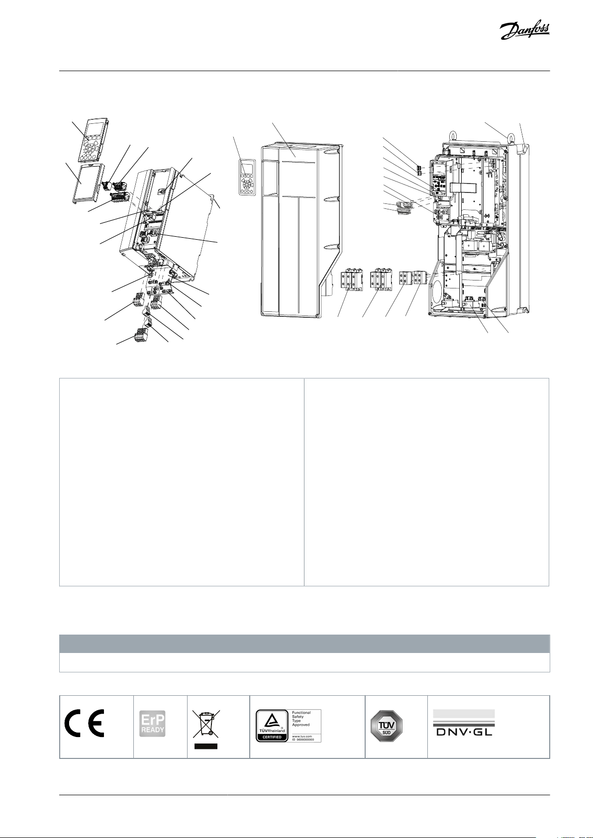
Local control panel (LCP)
2
Cover
3
RS485 fieldbus connector
4
Digital input/output connector
5
Digital input/output connector
6
Shielded cable grounding and relief
7
USB connector
8
RS485 termination switch
9
DIP switch for A53 and A54
10
Relay 1 (01, 02, 03)
11
Relay 2 (04, 05, 06)
12
Lifting ring
13
Mounting slot
14
Ground connection (PE)
15
Cable shield connector
16
Brake terminal (-81, +82)
17
Load sharing terminal (-88, +89)
18
Motor terminals 96 (U), 97 (V), 98 (W)
19
Mains input terminals 91 (L1), 92 (L2), 93 (L3)
20
LCP connector
VLT® AutomationDrive FC 301/FC 302
Operating Guide
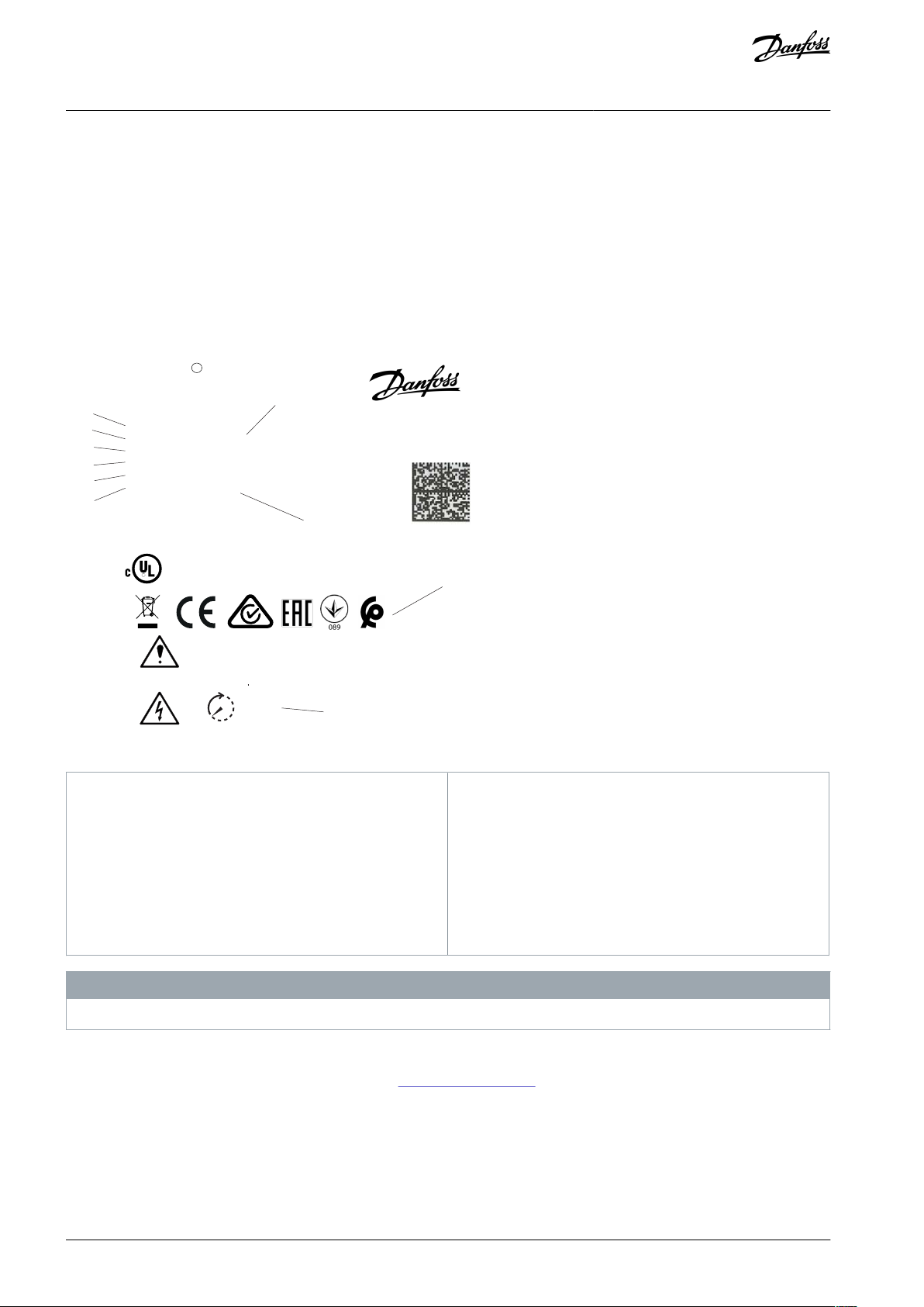
1.5.2 Exploded Views
Introduction
Illustration 1: Exploded View Enclosure Size A, IP20 (left) and Enclosure Size C, IP55/IP66 (right)
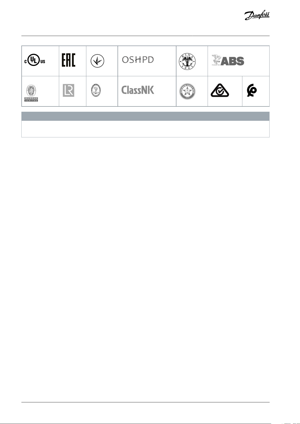
1.6 Type Approvals and Certifications
The following list is a selection of possible type approvals and certifications for Danfoss drives:
Drives of enclosure size T7 (525–690 V) are not UL listed.
Table 2: Type Approvals and Certifications
N O T I C E
AQ267037727118en-000101 / 130R0300 | 7Danfoss A/S © 2021.01
089
VLT® AutomationDrive FC 301/FC 302
Operating Guide
Introduction
N O T I C E
The specific approvals and certification for the drive are on the nameplate of the drive. For more information, contact the local
Danfoss office or partner.
For more information on UL 508C thermal memory retention requirements, refer to the section Motor Thermal Protection in the
product-specific Design Guide.
For more information on compliance with the European Agreement concerning International Carriage of Dangerous Goods by Inland Waterways (ADN), refer to the section ADN-compliant Installation in the product-specific Design Guide.
AQ267037727118en-000101 / 130R03008 | Danfoss A/S © 2021.01
VLT® AutomationDrive FC 301/FC 302
Operating Guide
2 Safety
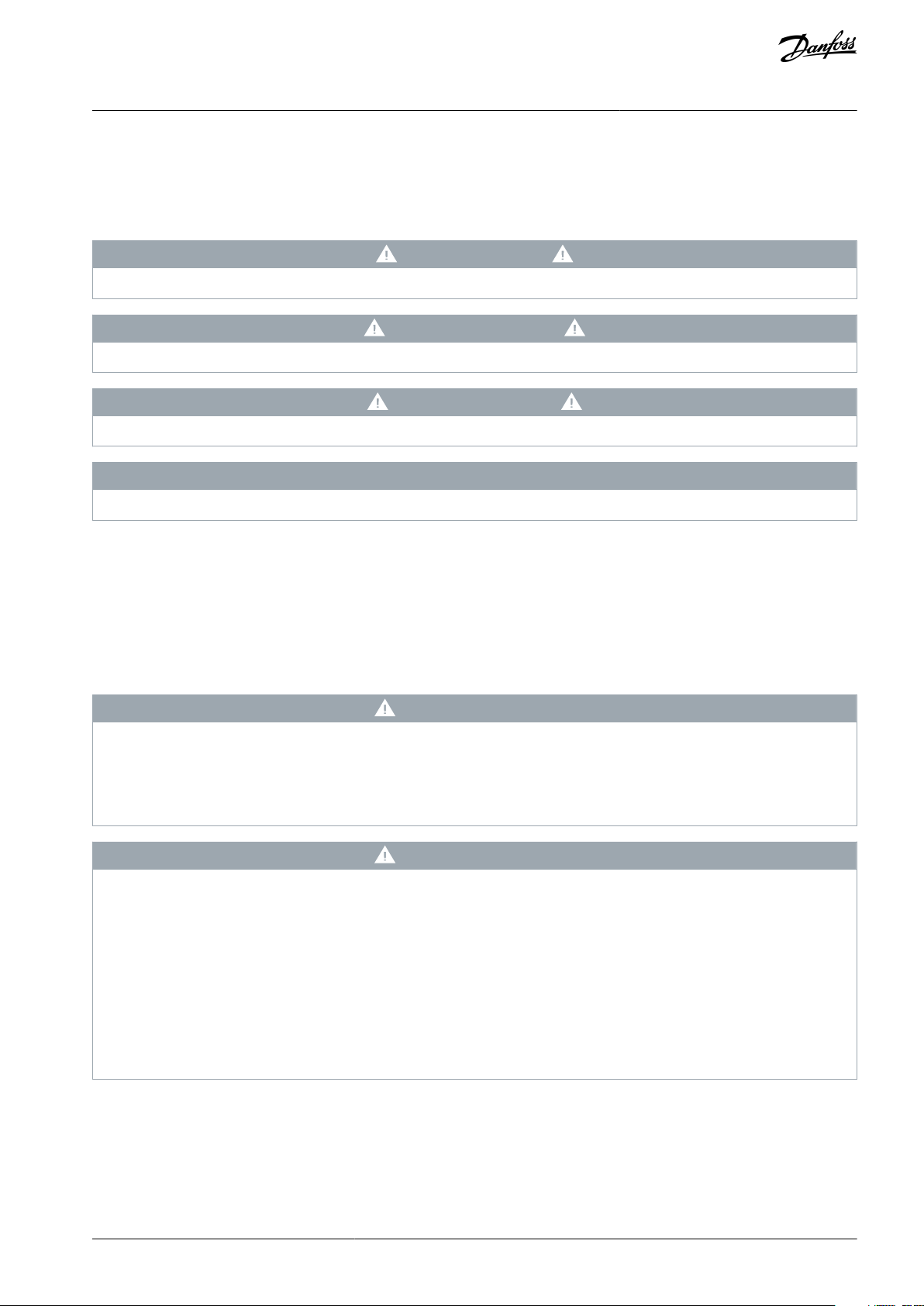
2.1 Safety Symbols
The following symbols are used in this manual:
D A N G E R
Indicates a hazardous situation which, if not avoided, will result in death or serious injury.
W A R N I N G
Indicates a hazardous situation which, if not avoided, could result in death or serious injury.
C A U T I O N
Indicates a hazardous situation which, if not avoided, could result in minor or moderate injury.
N O T I C E
Indicates information considered important, but not hazard-related (for example, messages relating to property damage).
Safety
2.2 Qualified Personnel
Correct and reliable transport, storage, installation, operation, and maintenance are required for the trouble-free and safe operation
of the drive. Only qualified personnel are allowed to install and operate this equipment.
Qualified personnel are defined as trained staff, who are authorized to install, commission, and maintain equipment, systems, and
circuits in accordance with pertinent laws and regulations. Also, the qualified personnel must be familiar with the instructions and
safety measures described in this manual.
2.3 Safety Precautions
W A R N I N G
HAZARDOUS VOLTAGE
AC drives contain hazardous voltage when connected to the AC mains or connected on the DC terminals. Failure to perform
installation, start-up, and maintenance by skilled personnel can result in death or serious injury.
Only skilled personnel must perform installation, start-up, and maintenance.
-
W A R N I N G
UNINTENDED START
When the drive is connected to the AC mains, DC supply, or load sharing, the motor may start at any time, causing risk of death,
serious injury, and equipment or property damage. The motor may start by activation of an external switch, a fieldbus command,
an input reference signal from the LCP or LOP, via remote operation using MCT 10 Set-up software, or after a cleared fault condi-
tion.
Press [Off] on the LCP before programming parameters.
-
Disconnect the drive from the mains whenever personal safety considerations make it necessary to avoid unintended motor
-
start.
Check that the drive, motor, and any driven equipment are in operational readiness.
-
AQ267037727118en-000101 / 130R0300 | 9Danfoss A/S © 2021.01
Voltage [V]
Minimum waiting time (minutes)
4715
200–240
0.25–3.7 kW (0.34–5 hp)
–
5.5–37 kW (7.5–50 hp)
380–500
0.25–7.5 kW (0.34–10 hp)
–
11–75 kW (15–100 hp)
525–600
0.75–7.5 kW (1–10 hp)
–
11–75 kW (15–100 hp)
525–690
–
1.5–7.5 kW (2–10 hp)
11–75 kW (15–100 hp)
VLT® AutomationDrive FC 301/FC 302
Operating Guide
Safety
W A R N I N G
DISCHARGE TIME
The drive contains DC-link capacitors, which can remain charged even when the drive is not powered. High voltage can be
present even when the warning indicator lights are off.
Failure to wait the specified time after power has been removed before performing service or repair work could result in death or
serious injury.
Stop the motor.
-
Disconnect AC mains, permanent magnet type motors, and remote DC-link supplies, including battery back-ups, UPS, and
-
DC-link connections to other drives.
Wait for the capacitors to discharge fully. The minimum waiting time is specified in the table Discharge time and is also visible
-
on the nameplate on top of the drive.
Before performing any service or repair work, use an appropriate voltage measuring device to make sure that the capacitors
-
are fully discharged.
Table 3: Discharge Time
W A R N I N G
LEAKAGE CURRENT HAZARD
Leakage currents exceed 3.5 mA. Failure to ground the drive properly can result in death or serious injury.
Ensure that the minimum size of the ground conductor complies with the local safety regulations for high touch current
-
equipment.
W A R N I N G
ROTATING SHAFTS
Contact with rotating shafts and electrical equipment can result in death or serious injury.
Ensure that only trained and qualified personnel perform installation, start-up, and maintenance.
-
Ensure that electrical work conforms to national and local electrical codes.
-
Follow the procedures in this guide.
-
W A R N I N G
UNINTENDED MOTOR ROTATION WINDMILLING
Unintended rotation of permanent magnet motors creates voltage and can charge the unit, resulting in death, serious injury, or
equipment damage.
Ensure that permanent magnet motors are blocked to prevent unintended rotation.
-
AQ267037727118en-000101 / 130R030010 | Danfoss A/S © 2021.01

VLT® AutomationDrive FC 301/FC 302
Operating Guide
C A U T I O N
INTERNAL FAILURE HAZARD
An internal failure in the drive can result in serious injury when the drive is not properly closed.
Ensure that all safety covers are in place and securely fastened before applying power.
-
Safety
AQ267037727118en-000101 / 130R0300 | 11Danfoss A/S © 2021.01
e30bd600.13
R
US LISTED
76 X1 E134261 IND. CONT. EQ.
UL Voltage 525-600 V
DANGER
See manual for special condition/mains fuse
voir manual de conditions speclales/fusibles
`
15 min.
VLT
R
Automation Drive
T/C: FC-302P75KT7P21H2XGCXXXSXXXXAXBXCXXXXDX
P/N: 134G6302 S/N: 999999G999
55kW / 75 kW; 75kW / 90 kW (NO)
IN: 3x525-690V 50/60Hz 87/86A; 161/145A (NO)
OUT: 3x0-Vin 0-590Hz 87/83A; 105/100A (NO)
Type 1/ IP21 Tamb. 50
C /122 F
o o
MADE IN DENMARK
Danfoss A/S
6340 NordborgDenmark
www.danfoss.com
1
2
3
4
5
6
7
8
9
10
1
Type code
2
Code number
3
Serial number
4
Power rating
5
Input voltage, frequency, and current (at low/high
voltages)
6
Output voltage, frequency, and current (at low/high
voltages)
7
Enclosure size and IP rating
8
Maximum ambient temperature
9
Certifications
10
Discharge time (Warning)
VLT® AutomationDrive FC 301/FC 302
Operating Guide
Mechanical Installation
3 Mechanical Installation
3.1 Unpacking
3.1.1 Items Supplied
Items supplied vary according to product configuration.
•
Make sure that the items supplied and the information on the nameplate correspond to the order confirmation.
•
Check the packaging and the drive visually for damage caused by inappropriate handling during shipment. File any claim for
damage with the carrier. Retain damaged parts for clarification.
Illustration 2: Product Nameplate (Example)
Do not remove the nameplate from the drive (loss of warranty).
3.1.2 Storage
Ensure that the requirements for storage are fulfilled, see 8.4 Ambient Conditions.
N O T I C E
AQ267037727118en-000101 / 130R030012 | Danfoss A/S © 2021.01
a
a
e30bd528.10
Enclosure
A1–A5
B1–B4
C1, C3
C2, C4
a [mm (in)]
100 (3.9)
200 (7.8)
200 (7.8)
225 (8.9)
VLT® AutomationDrive FC 301/FC 302
Operating Guide
Mechanical Installation
3.2 Installation Environment
N O T I C E
REDUCED LIFETIME
In environments with airborne liquids, particles, or corrosive gases, ensure that the IP/Type rating of the equipment matches the
installation environment. Failure to meet requirements for ambient conditions can reduce lifetime of the drive.
Ensure that requirements for air humidity, temperature, and altitude are met.
-
Vibration and shock
The drive complies with requirements for units mounted on the walls and floors of production premises, and in panels bolted to
walls or floors. For detailed ambient conditions, refer to 8.4 Ambient Conditions.
3.3 Mounting
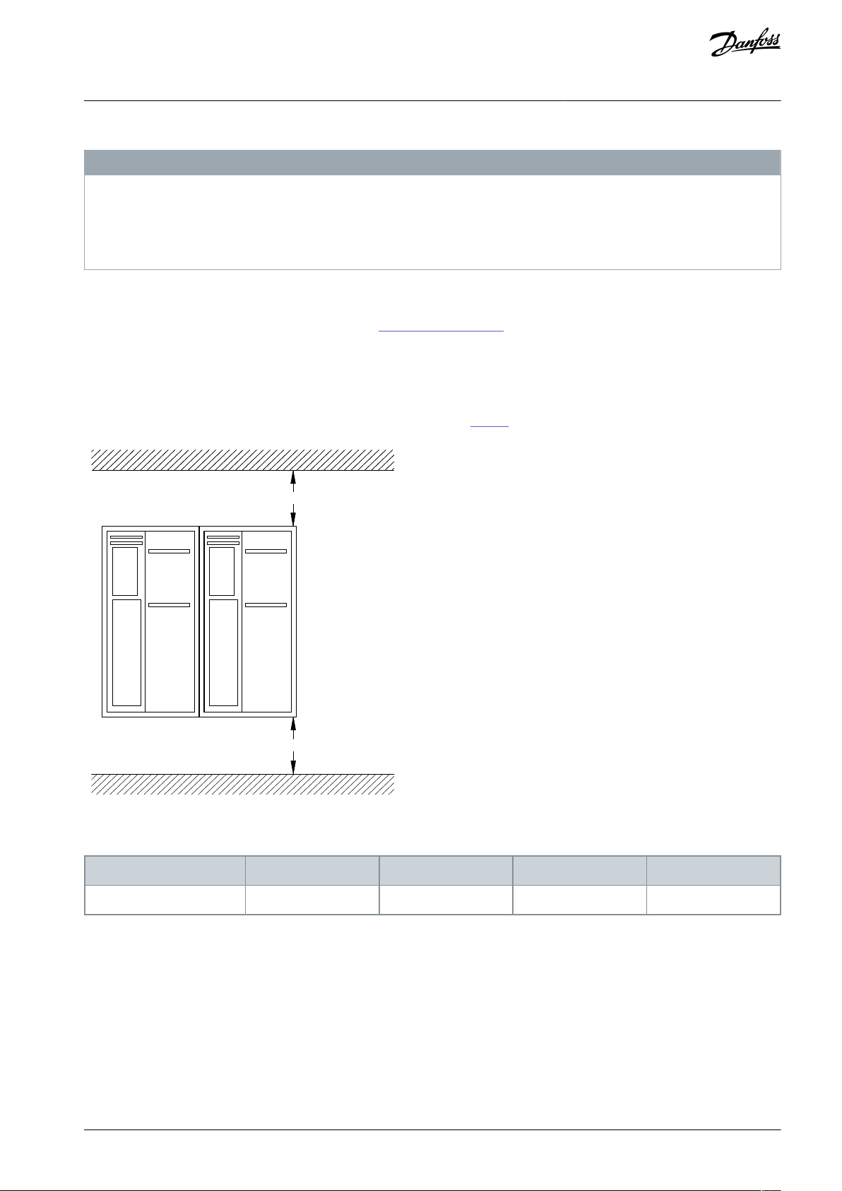
3.3.1 Cooling
•
Ensure that top and bottom clearance for air cooling is provided. See Table 4 for clearance requirements.
Illustration 3: Top and Bottom Cooling Clearance
Table 4: Minimum Airflow Clearance Requirements
AQ267037727118en-000101 / 130R0300 | 13Danfoss A/S © 2021.01
e30bd504.11
VLT® AutomationDrive FC 301/FC 302
Operating Guide
Mechanical Installation
3.3.2 Lifting
W A R N I N G
HEAVY LOAD
Unbalanced loads can fall and loads can tip over. Failure to take proper lifting precautions increases risk of death, serious injury,
or equipment damage.
Never walk under suspended loads.
-
To guard against injury, wear personal protective equipment such as gloves, safety glasses, and safety shoes.
-
Be sure to use lifting devices with the appropriate weight rating. To determine a safe lifting method, check the weight of the
-
unit.
The angle from the top of the drive module to the lifting cables has an impact on the maximum load force on the cable. This
-
angle must be 65° or greater. Attach and dimension the lifting cables properly.
•
To determine a safe lifting method, check the weight of the unit in 8.9 Power Ratings, Weight, and Dimensions.
•
Ensure that the lifting device is suitable for the task.
•
If necessary, plan for a hoist, crane, or forklift with the appropriate rating to move the unit.
•
For lifting, use hoist rings on the unit, when provided.
3.3.3 Mounting
Procedure
1.
Ensure that the strength of the mounting location supports the unit weight.
The drive allows side-by-side installation.
2.
Locate the unit as near to the motor as possible. Keep the motor cables as short as possible.
3.
Mount the unit vertically to a solid flat surface or to the optional backplate to provide cooling airflow.
4.
Use the slotted mounting holes on the unit for wall mount, when provided.
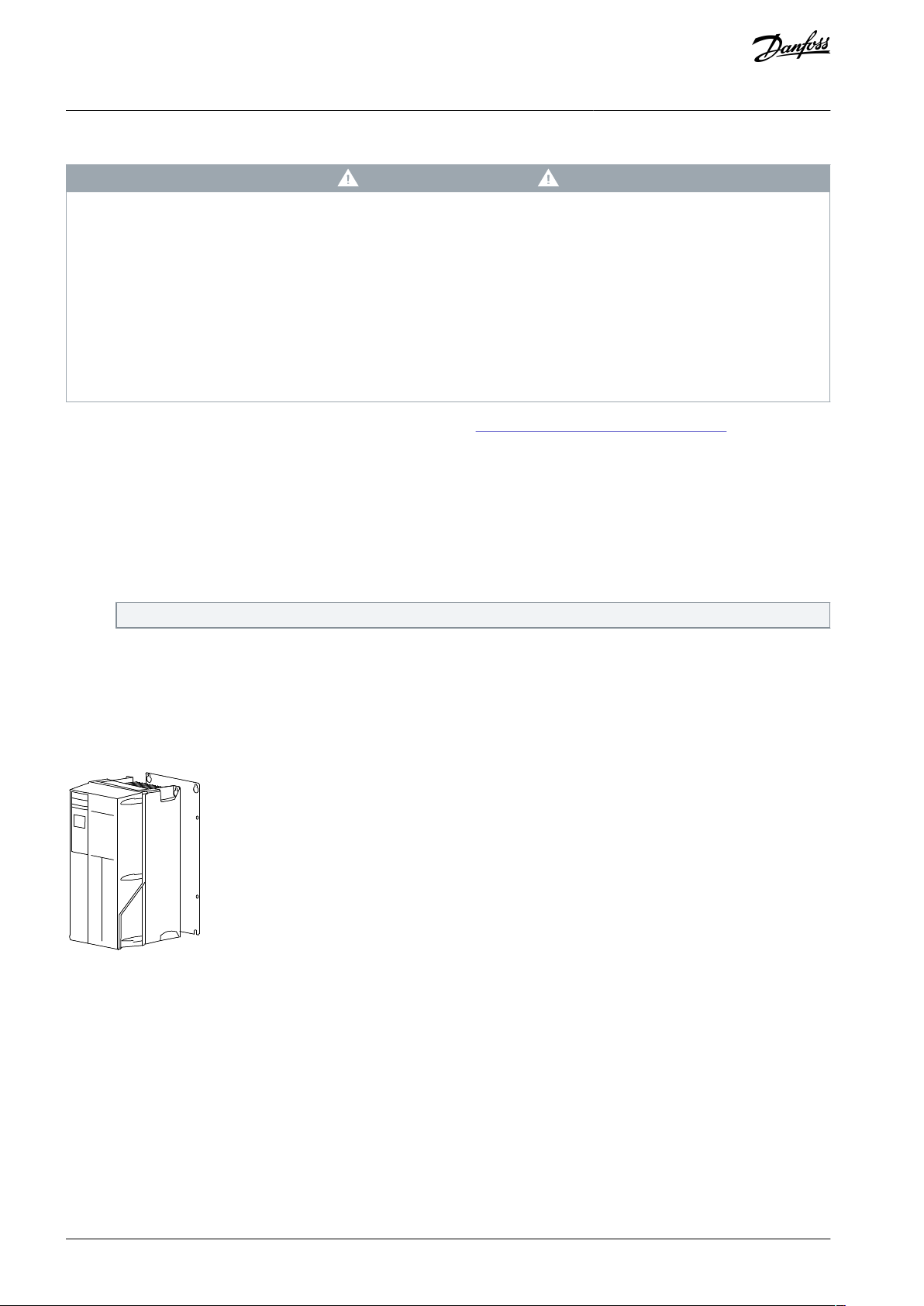
3.3.3.1 Mounting with Mounting Plate and Railings
A mounting plate is required when mounted on railings.
Illustration 4: Proper Mounting with Mounting Plate
AQ267037727118en-000101 / 130R030014 | Danfoss A/S © 2021.01

VLT® AutomationDrive FC 301/FC 302
Operating Guide
Electrical Installation
4 Electrical Installation
4.1 Safety Instructions
See 2.3 Safety Precautions for general safety instructions.
W A R N I N G
INDUCED VOLTAGE
Induced voltage from output motor cables that run together can charge equipment capacitors, even with the equipment turned
off and locked out. Failure to run output motor cables separately or to use shielded cables could result in death or serious injury.
Run output motor cables separately or use shielded cables.
-
Simultaneously lock out all the drives.
-
W A R N I N G
SHOCK HAZARD
The unit can cause a DC current in the PE conductor. Failure to use a Type B residual current-operated protective device (RCD)
may lead to the RCD not providing the intended protection and therefore may result in death or serious injury.
When an RCD is used for protection against electrical shock, only a Type B device is allowed on the supply side.
-
Overcurrent protection
•
Extra protective equipment, such as short-circuit protection or motor thermal protection between drive and motor, is required
for applications with multiple motors.
•
Input fusing is required to provide short circuit and overcurrent protection. If not factory-supplied, the installer must provide
fuses. See maximum fuse ratings in 8.7.2 CE Compliance and 8.7.3 UL Compliance.
Wire type and ratings
•
All wiring must comply with local and national regulations regarding cross-section and ambient temperature requirements.
•
Power connection wire recommendation: Minimum 75 °C (167 °F) rated copper wire. See Table 29 to Table 40, and 8.5.1 Cable
Lengths and Cross-sections for Control Cables for recommended wire sizes and types.
4.2 EMC-compliant Installation
To obtain an EMC-compliant installation, follow the instructions provided in 4.3 Grounding, 4.4 Wiring Schematic, 4.5 Connecting
the Motor, and 4.7 Control Wiring.
N O T I C E
POTENTIAL EQUALIZATION
Risk of burst transient when the ground potential between the drive and the control system is different. Install equalizing cables
between the system components. Recommended cable cross-section: 16 mm2 (6 AWG).
4.3 Grounding
W A R N I N G
LEAKAGE CURRENT HAZARD
Leakage currents exceed 3.5 mA. Failure to ground the drive properly can result in death or serious injury.
Ensure that the minimum size of the ground conductor complies with the local safety regulations for high touch current
-
equipment.
For electrical safety
•
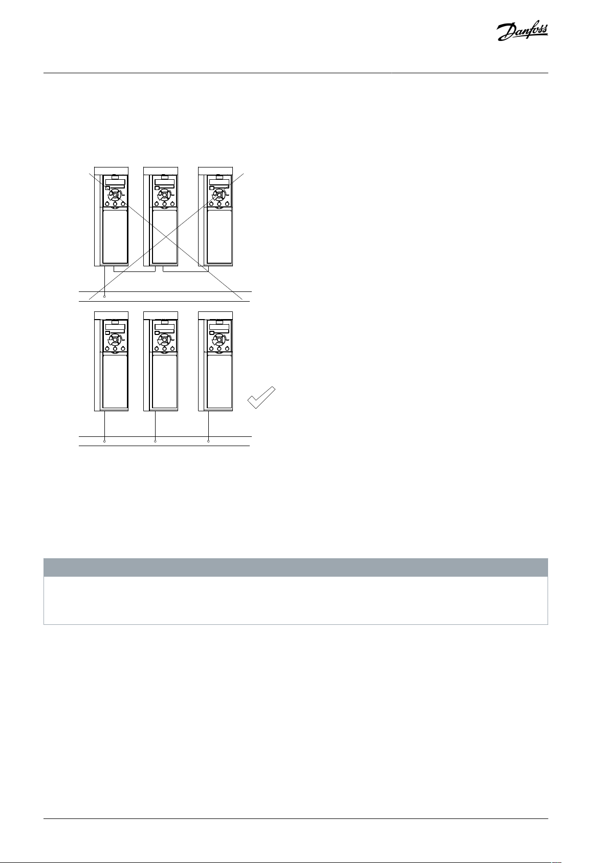
Ground the drive in accordance with applicable standards and directives.
•
Use a dedicated ground wire for input power, motor power, and control wiring.
•
Do not ground 1 drive to another in a daisy-chain fashion (see Illustration 5.)
AQ267037727118en-000101 / 130R0300 | 15Danfoss A/S © 2021.01
e30bc500.11
FC 1
FC 1
FC 2
FC 2
FC 3
FC 3
PE
PE
VLT® AutomationDrive FC 301/FC 302
Operating Guide
•
Keep the ground wire connections as short as possible.
•
Follow motor manufacturer wiring requirements.
•
Minimum cable cross-section for the ground wires: 10 mm2 (7 AWG).
•
Separately terminate individual ground wires, both complying with the dimension requirements.
Electrical Installation
Illustration 5: Grounding Principle
For EMC-compliant installation
•
Establish electrical contact between the cable shield and the drive enclosure by using metal cable glands or by using the clamps
provided on the equipment.
•
Use high-strand wire to reduce burst transient.
•
Do not use pigtails.
N O T I C E
POTENTIAL EQUALIZATION
Risk of burst transient when the ground potential between the drive and the control system is different. Install equalizing cables
between the system components. Recommended cable cross-section: 16 mm2 (6 AWG).
AQ267037727118en-000101 / 130R030016 | Danfoss A/S © 2021.01
130BD599.11
––
Motor
Analog Output
ON=Terminated
OFF=Open
91 (L1)
92 (L2)
93 (L3)
PE
88 (-)
89 (+)
53 (A IN)
54 (A IN)
37 (D IN)
1)
18 (D IN)
10
V DC
15 mA 130/200 mA
+ - + -
(U) 96
(V) 97
(W) 98
(PE) 99
(P RS485) 68
(N RS485) 69
0 V
5V
S801
0/4–20 mA
RS-485
03
240 V AC, 2 A
24 V DC
02
01
05
04
06
24
V (NPN)
0 V (PNP)
0 V (PNP)
24
V (NPN)
19 (D IN)
24
V (NPN)
0 V (PNP)
24
V
0
V
0
V (PNP)
24 V (NPN)
(D IN/OUT
)
1)
0 V
24
V
29
24
V (NPN)
0 V (PNP)
0
V (PNP)
24 V (NPN)
33 (D IN)
32 (D IN)
1 2
ON
S201
ON
21
S202
ON=0/4–20 mA
95
P 5-00
21
ON
S801
(R+) 82
(R-) 81
: Chassis
240 V AC, 2 A
400 V AC, 2 A
: PE
3-phase
power
input
+10 V DC
DC bus
0/-10 V DC to
+10 V DC
0/4–20 mA
0/-10 V DC to
+10 V DC
0/4–20 mA
50 (+10 V OUT)
55 (COM A IN)
12 (+24 V OUT)
13 (+24 V OUT)
20 (COM D IN)
27 (D IN/OUT)
Switch mode
power supply
Brake
resistor
Relay 1
Relay 2
1)
(COM A OUT) 39
(A OUT) 42
: Ground
: Ground 1
: Ground 2
(COM RS485) 61
2)
RS485
interface
OFF=0/-10 V DC
to +10 V DC
A
Analog
D
Digital
1
Terminal 37 (optional) is used for Safe Torque Off
(STO). For installation instructions, refer to the VLT
®
Safe Torque Off Operating Guide. For FC 301, terminal 37 is only included in enclosure size A1. Relay 2
and terminal 29 have no function in FC 301.
2
Do not connect cable shield.
VLT® AutomationDrive FC 301/FC 302
Operating Guide
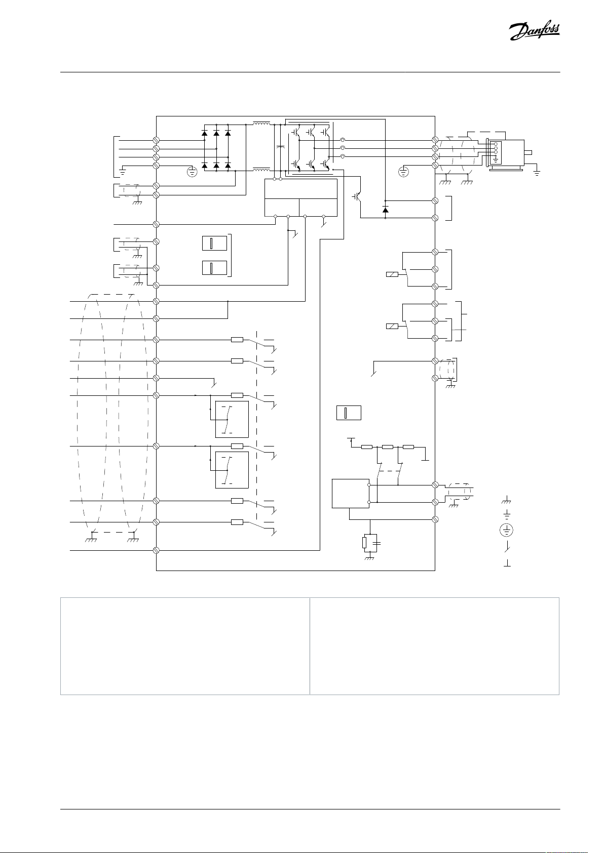
4.4 Wiring Schematic
Electrical Installation
Illustration 6: Basic Wiring Schematic
Read more in EMC-Compliant Installation.
AQ267037727118en-000101 / 130R0300 | 17Danfoss A/S © 2021.01
e30bd531.11
U
V
W
96
97
98
VLT® AutomationDrive FC 301/FC 302
Operating Guide
Electrical Installation
4.5 Connecting the Motor
W A R N I N G
INDUCED VOLTAGE
Induced voltage from output motor cables that run together can charge equipment capacitors, even with the equipment turned
off and locked out. Failure to run output motor cables separately or to use shielded cables could result in death or serious injury.
Run output motor cables separately or use shielded cables.
-
Simultaneously lock out all the drives.
-
•
Run output separately or
•
Use shielded cables.
•
Comply with local and national electrical codes for cable sizes. For maximum wire sizes, see Table 29 to Table 40.
•
Follow motor manufacturer wiring requirements.
•
Motor wiring knockouts or access panels are provided at the base of IP21 (NEMA 1/12) and higher units.
•
Do not wire a starting or pole-changing device (for example a Dahlander motor or slip ring asynchronous motor) between the
drive and the motor.
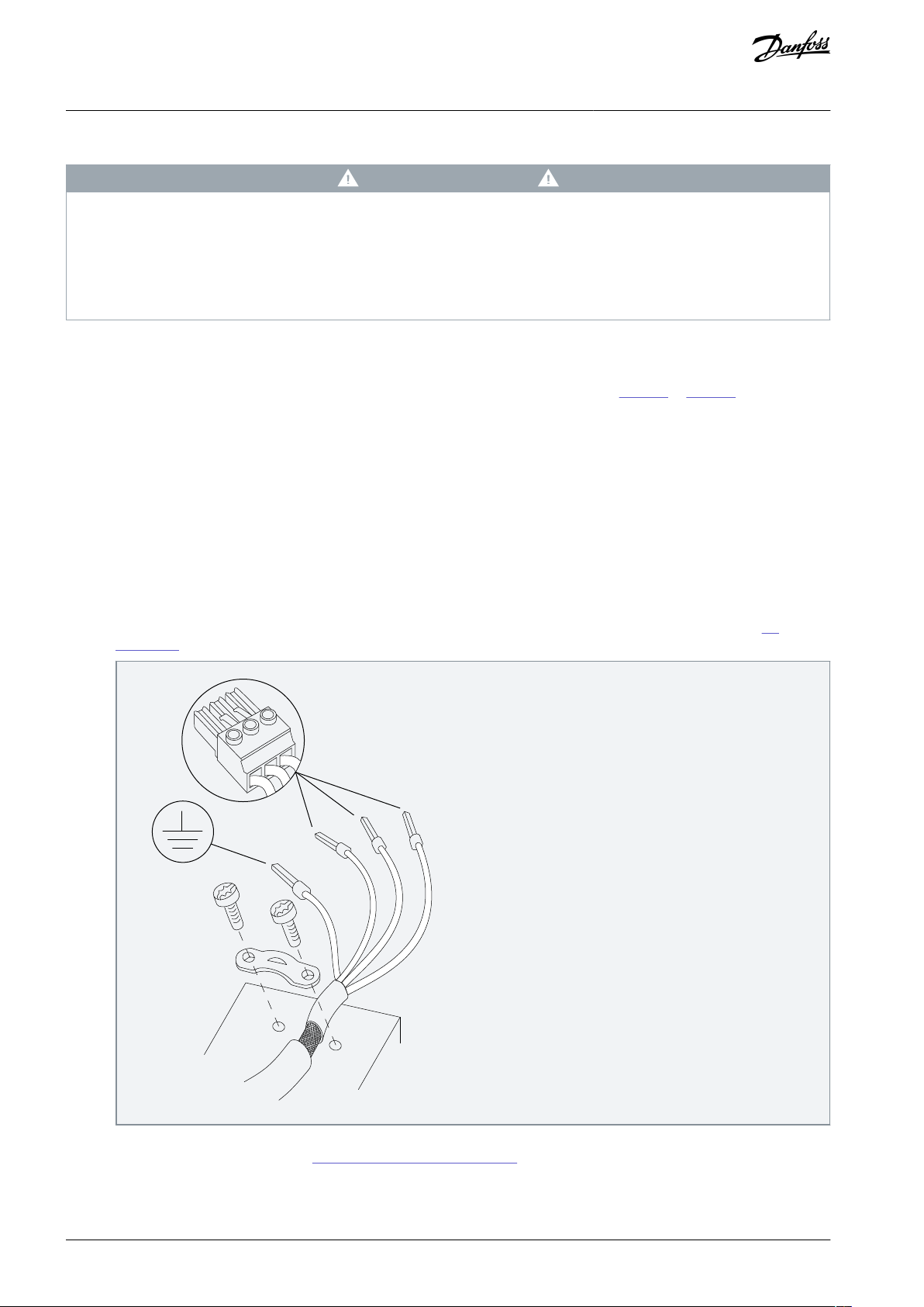
4.5.1 Grounding the Cable Shield
Procedure
1.
Strip a section of the outer cable insulation.
2.
Position the stripped wire under the cable clamp to esatblish mechanical fixation and electrical contact between the cable
shield and ground.
3.
Connect the ground wire to the nearest grounding terminal in accordance with the grounding instructions, see 4.3
Grounding.
4.
Connect the 3-phase motor wiring to terminals 96 (U), 97 (V), and 98 (W).
5.
Torque-tighten the terminals, see 8.8 Connection Tightening Torques.
Example
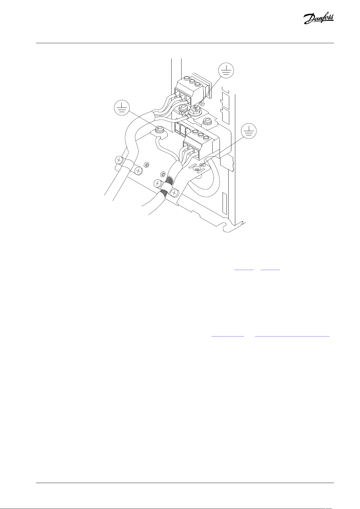
Mains input, motor, and grounding for basic drives. Actual configurations vary with unit types and optional equipment.
AQ267037727118en-000101 / 130R030018 | Danfoss A/S © 2021.01
+DC
BR-
B
M A I N S
L1 L2 L3
91 92 93
RELAY 1 RELAY 2
99
U V W
MOTOR
99
130BF048.11
VLT® AutomationDrive FC 301/FC 302
Operating Guide
Electrical Installation
Illustration 7: Example of Motor, Mains, and Ground Wiring
4.6 Connecting AC Mains
•
Size the wiring based on the input current of the drive. For maximum wire sizes, see Table 29 to Table 40.
•
Comply with local and national electrical codes for cable sizes.
4.6.1 Connecting the Drive to Mains
Procedure
1.
Connect the 3-phase AC input power wiring to terminals L1, L2, and L3.
2.
Depending on the configuration of the equipment, connect the input power to the mains input terminals or the input disconnect.
3.
Ground the cable in accordance with the grounding instructions, see 4.3 Grounding and 4.5.1 Grounding the Cable Shield.
4.
When supplied from an isolated mains source (IT mains or floating delta) or TT/TN-S mains with a grounded leg (grounded
delta), ensure that parameter 14-50 RFI Filter is set to [0] Off. This setting prevents damage to the DC link and reduces
ground capacity currents in accordance with IEC 61800-3.
4.7 Control Wiring
•
Isolate the control wiring from the high-power components in the drive.
•
When the drive is connected to a thermistor, enusre that the thermistor control wiring is shielded and reinforced/double insulated. A 24 V DC supply voltage is recommended.
4.7.1 Safe Torque Off (STO)
To run STO, additional wiring for the drive is required.
Refer to the VLT® Frequency Converters Safe Torque Off Operating Guide for further information.
AQ267037727118en-000101 / 130R0300 | 19Danfoss A/S © 2021.01
•
•
•
•
•
e30ba902.11
L1 L2 L3
U V W
02 01
A1
A2
Drive
Output
relay
Command circuit
220 V AC
Mechanical
brake
Shaft
Motor
Frewheeling
diode
Brake
380 V AC
Output
contactor
input
power circuit
Inspect for
Description
√
Auxiliary
equipment
Look for auxiliary equipment, switches, disconnects, or input fuses/circuit breakers residing on the input power side of the drive, or output side to the motor. Ensure that they are ready for full-speed operation.
Check the function and installation of any sensors used for feedback to the drive.
Remove any power factor correction capacitors on the motor.
Adjust any power factor correction capacitors on the mains side and ensure that they are dampened.
Cable routing
Ensure that the motor wiring and control wiring are separated, shielded, or in 3 separate metallic conduits for high-frequency interference isolation.
VLT® AutomationDrive FC 301/FC 302
Operating Guide
Electrical Installation
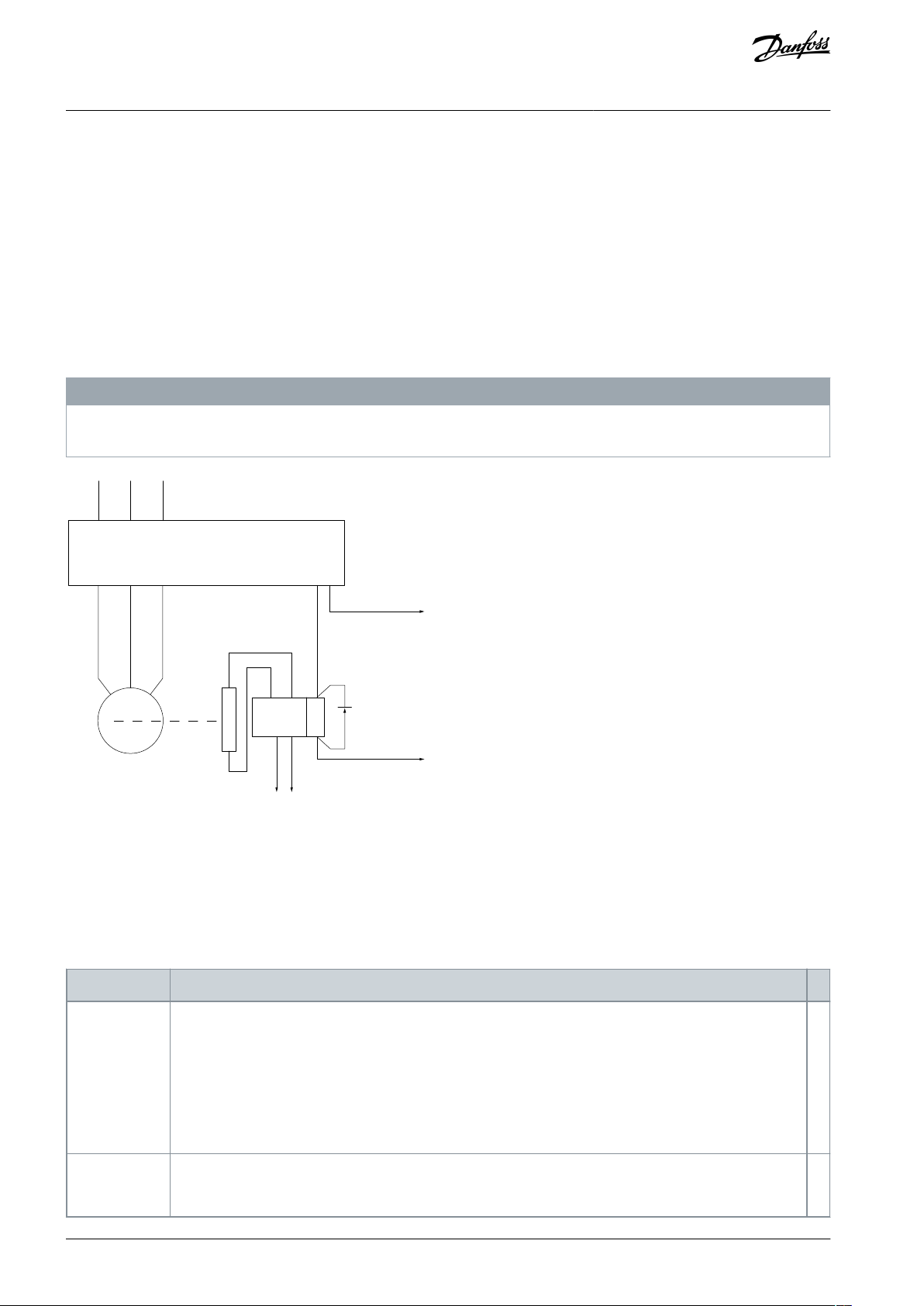
4.7.2 Mechanical Brake Control
In hoisting/lowering applications, it is necessary to control an electro-mechanical brake.
•
Control the brake using any relay output or digital output (terminal 27 or 29).
•
Keep the output closed (voltage-free) as long as the drive is unable to keep the motor at standstill, for example due to the load
being too heavy.
•
Select [32] Mechanical brake control in parameter group 5-4* Relays for applications with an electromechanical brake.
•
The brake is released when the motor current exceeds the value in parameter 2-20 Release Brake Current.
•
The brake is engaged when the output frequency is less than the frequency set in parameter 2-21 Activate Brake Speed [RPM] or
parameter 2-22 Activate Brake Speed [Hz], and only if the drive carries out a stop command.
If the drive is in alarm mode or in an overvoltage situation, the mechanical brake immediately closes.
N O T I C E
The drive is not a safety device. It is the responsibility of the system designer to integrate safety devices according to relevant
national crane/lift regulations.
Illustration 8: Connecting the Mechanical Brake to the Drive
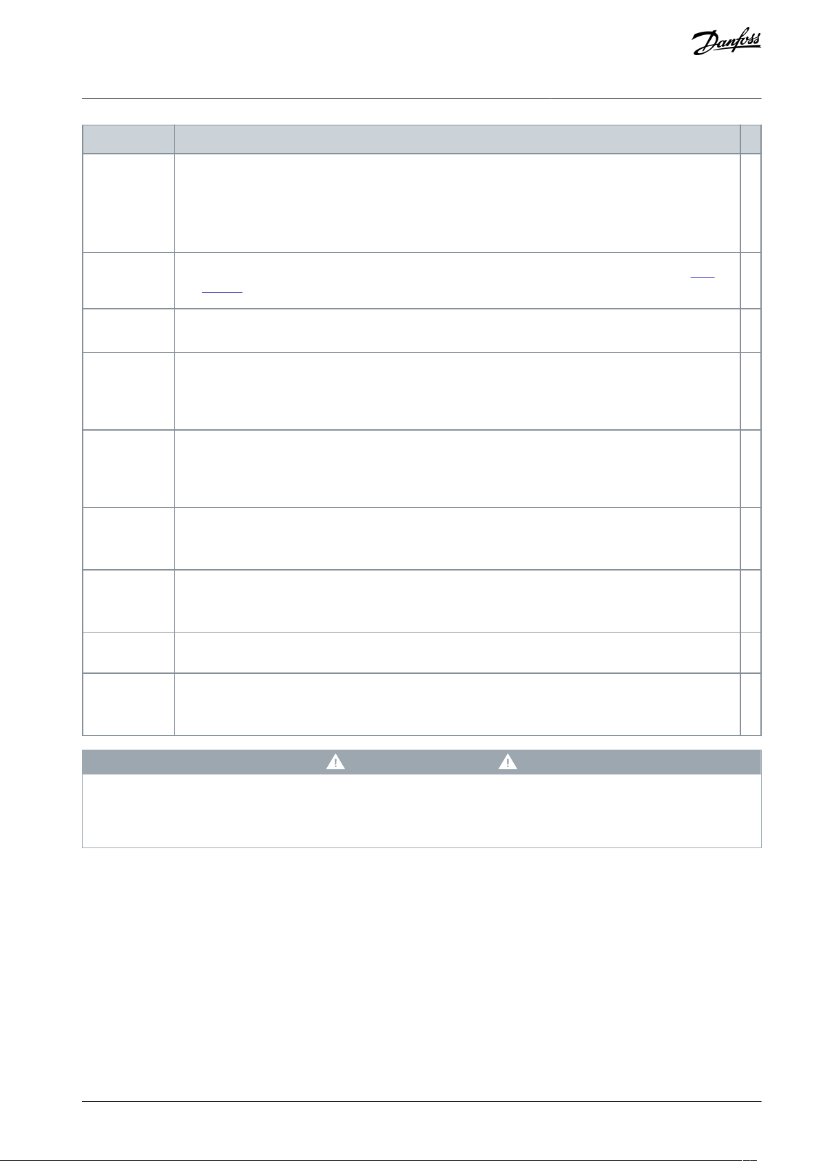
4.8 Installation Check List
Before completing installation of the unit, inspect the entire installation as detailed in the following table. Check and mark the items
when completed.
Table 5: Installation Check List
AQ267037727118en-000101 / 130R030020 | Danfoss A/S © 2021.01
•
•
•
•
•
•••
•••••
•••
Inspect for
Description
√
Control wiring
Check for broken or damaged wires and loose connections.
Check that the control wiring is isolated from power and motor wiring for noise immunity.
Check the voltage source of the signals, if necessary.
The use of shielded cable or twisted pair is recommended. Ensure that the shield is terminated correctly.
Cooling clearance
Ensure that the top and bottom clearance is adequate to ensure proper airflow for cooling, see 3.3.1
Cooling.
Ambient conditions
Check that requirements for ambient conditions are met.
Fusing and circuit breakers
Check for proper fusing or circuit breakers.
Check that all fuses are inserted firmly and are in operational condition, and that all circuit breakers are
in the open position.
Grounding
Check for sufficient ground connections and ensure that those connections are tight and free of oxidation.
Grounding to conduit, or mounting the back panel to a metal surface, is not a suitable grounding.
Input and output power wiring
Check for loose connections.
Check that the motor and mains cables are in separate conduit or separated shielded cables.
Panel interior
Inspect that the unit interior is free of dirt, metal chips, moisture, and corrosion.
Check that the unit is mounted on an unpainted metal surface.
Switches
Ensure that all switch and disconnect settings are in the proper positions.
Vibration
Check that the unit is mounted solidly, or that shock mounts are used, as necessary.
Check for an unusual amount of vibration.
VLT® AutomationDrive FC 301/FC 302
Operating Guide
Electrical Installation
C A U T I O N
INTERNAL FAILURE HAZARD
An internal failure in the drive can result in serious injury when the drive is not properly closed.
Ensure that all safety covers are in place and securely fastened before applying power.
-
AQ267037727118en-000101 / 130R0300 | 21Danfoss A/S © 2021.01

VLT® AutomationDrive FC 301/FC 302
Operating Guide
Commissioning
5 Commissioning
5.1 Safety Instructions
See chapter Safety for general safety instructions.
W A R N I N G
HAZARDOUS VOLTAGE
AC drives contain hazardous voltage when connected to the AC mains or connected on the DC terminals. Failure to perform
installation, start-up, and maintenance by skilled personnel can result in death or serious injury.
Only skilled personnel must perform installation, start-up, and maintenance.
-
N O T I C E
The front covers with warning signs are an integrated part of the drive and considered safety covers. The covers must be in place
before applying power and at all times.
5.1.1 Before Applying Power
Procedure
1.
Close the safety cover properly.
2.
Check that all cable glands are firmly tightened.
3.
Ensure that input power to the unit is off and locked out. Do not rely on the drive disconnect switches for input power
isolation.
4.
Verify that there is no voltage on input terminals L1 (91), L2 (92), and L3 (93), phase-to-phase, and phase-to-ground.
5.
Verify that there is no voltage on output terminals 96 (U), 97 (V), and 98 (W), phase-to-phase, and phase-to-ground.
6.
Confirm continuity of the motor by measuring Ω values on U–V (96–97), V–W (97–98), and W–U (98–96).
7.
Check for proper grounding of the drive and the motor.
8.
Inspect the drive for loose connections on the terminals.
9.
Confirm that the supply voltage matches the voltage of the drive and the motor.
AQ267037727118en-000101 / 130R030022 | Danfoss A/S © 2021.01
•
•
e30bf714.11
Auto
On
Reset
Hand
On
Off
Status
Quick
Menu
Main
Menu
Alarm
Log
Back
Cancel
Info
OK
Status
1(1)
36.4 kW
Auto Remote Ramping
0.000
On
Alarm
Warn.
7.83 A
799 RPM
53.2 %
1
2
3
16
17
4
15
14
13
12
5
6
7
8 9 10 11
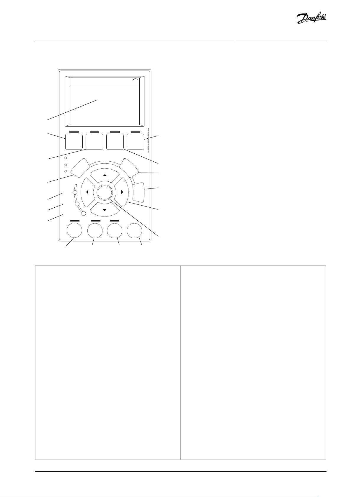
1
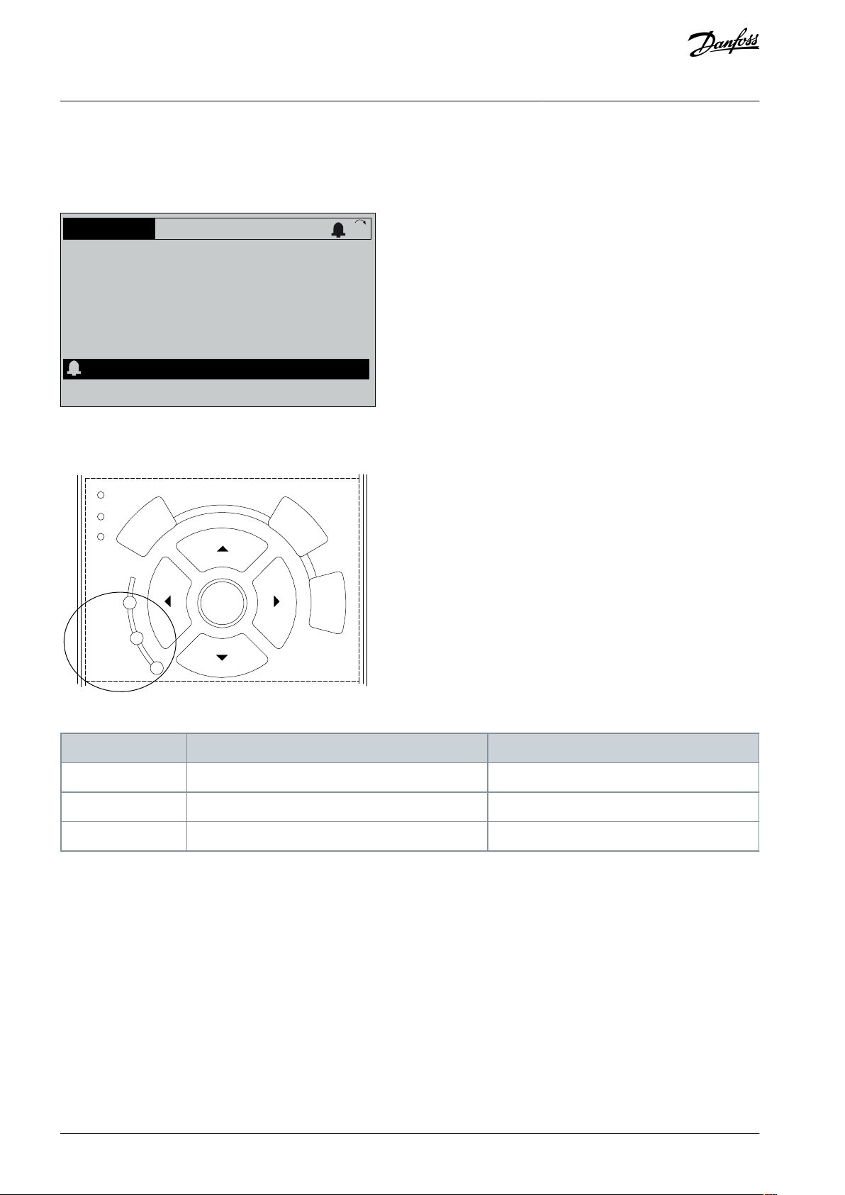
The information shown in the display area depends
on the selected function or menu (in this case Quick
Menu Q3-13 Display Settings).
2
[Status] shows operational status.
3
[Quick Menu] allows access to programming parameters for initial set-up instructions and many detailed application instructions.
4
[Back] reverts to the previous step or list in the menu
structure.
5
A green indicator light indicates that power is on.
6
A yellow indicator light comes on when a warning is
active. A text appears in the display area identifying
the problem.
7
A red flashing indicator light indicates a fault condition, and an alarm text is shown.
8
[Hand On] puts the drive in local control mode, so
that it responds to the LCP.
An external stop signal by control input or serial
communication overrides local [Hand On] key.
9
[Off] stops the motor but does not remove power to
the drive.
10
[Auto On] puts the system in remote operational
mode.
Responds to an external start command by control terminals or serial communication.
11
[Reset] resets the drive manually after a fault has
been cleared.
12
[OK] gives access to parameter groups or enables a
selection.
13
[▵][▹] [▿] [◃] enables moving between items in the
menu.
14
[Info] shows a definition of the function being
shown.
15
[Cancel] cancels the last change or command as
long as the display mode is not changed.
16
[Main Menu] gives access to all programming parameters.
17
[Alarm Log] shows a list of current warnings, the last
10 alarms, and the maintenance log.
VLT® AutomationDrive FC 301/FC 302
Operating Guide
5.2 Local Control Panel Operation
Commissioning
Illustration 9: Graphical Local Control Panel (GLCP)
AQ267037727118en-000101 / 130R0300 | 23Danfoss A/S © 2021.01

Parameter 1-10 Motor Construction
ASM
SPM
IPM
SynRM
PMaSynRM
Parameter 1-20 Motor Power [kW]/parameter 1-21 Motor Power
[hp]XParameter 1-22 Motor Voltage
X
Parameter 1-23 Motor Frequency
XXX
Parameter 1-24 Motor Current
XXXXX
Parameter 1-25 Motor Nominal Speed
XXXXX
Parameter 1-26 Motor Cont. Rated
XXX
X
Parameter 1-39 Motor Poles
XXX
X
VLT® AutomationDrive FC 301/FC 302
Operating Guide
5.3 System Set-up
Procedure
1.
Perform automatic motor adaption (AMA):
a.
Set the basic motor parameters before performing AMA.
Table 6: Basic Parameters to be Checked before AMA
Commissioning
b.
Optimize the compatibility between motor and drive via parameter 1-29 Automatic Motor Adaptation (AMA).
2.
Check motor rotatation.
3.
If encoder feedback is used, perform the following steps:
a.
Select [0] Speed open loop in parameter 1-00 Configuration Mode.
b.
Select [1] 24V encoder in parameter 7-00 Speed PID Feedback Source.
Press [Hand On].
c.
d.
Press [▹] for positive speed reference (parameter 1-06 Clockwise Direction at [0]).
e.
In parameter 16-57 Feedback [RPM], check that the feedback is positive.
AQ267037727118en-000101 / 130R030024 | Danfoss A/S © 2021.01
e30bt865.10
Encoder
Mechanical brake
Motor
Gearbox
Load
Transmission
Brake resistor
VLT® AutomationDrive FC 301/FC 302
Operating Guide
Basic I/O Configuration
6 Basic I/O Configuration
6.1 Application Examples
The examples in this section are intended as a quick reference for common applications.
•
Parameter settings are the regional default values unless otherwise indicated (selected in parameter 0-03 Regional Settings).
•
Parameters associated with the terminals and their settings are shown next to the drawings.
•
Required switch settings for analog terminals A53 or A54 are also shown.
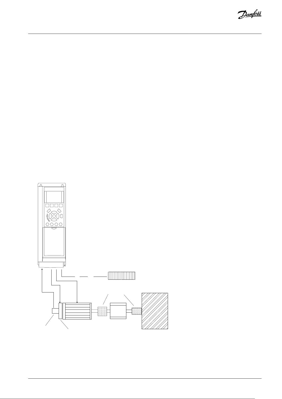
6.1.1 Programming a Closed-loop Drive System
A closed-loop drive system usually consists of:
•
Motor.
•
Drive.
•
Encoder (as feedback system).
•
Mechanical brake.
•
Brake resistor (for dynamic braking).
•
Transmission.
•
Gear box.
•
Load.
Applications demanding mechanical brake control typically need a brake resistor.
Illustration 10: Basic Set-up for Closed-loop Speed Control
AQ267037727118en-000101 / 130R0300 | 25Danfoss A/S © 2021.01
Parameters
+24 V
+24 V
D IN
D IN
D IN
COM
D IN
D IN
D IN
D IN
+10 V
A IN
A IN
COM
A OUT
COM
12
13
18
19
20
27
29
32
33
37
50
53
54
55
42
39
e30bb929.11
Drive
Function
Setting
Parameter 1-29 Automatic Motor Adaptation (AMA)
[1] Enable complete AMA
Parameter 5-12 Terminal 27 Digital Input
[2]* Coast inverse
*=Default value
Notes/comments:
Set parameter group 1-2* Motor Data according to motor nameplate.
Parameters
Drive
+24 V
+24 V
D IN
D IN
D IN
COM
D IN
D IN
D IN
D IN
+10 V
A IN
A IN
COM
A OUT
COM
12
13
18
19
20
27
29
32
33
37
50
53
54
55
42
39
e30bb930.11
Function
Setting
Parameter 1-29 Automatic Motor Adaptation (AMA)
[1] Enable complete AMA
Parameter 5-12 Terminal 27 Digital Input
[0] No operation
*=Default value
Notes/comments:
Parameter group 1-2* Motor Data must be set according to motor.
VLT® AutomationDrive FC 301/FC 302
Operating Guide
6.1.2 Wiring Configuration for Automatic Motor Adaptation (AMA)
Table 7: Wiring Configuration for AMA with T27 Connected
Basic I/O Configuration
6.1.3 Wiring Configuration for Automatic Motor Adaptation without T27
Table 8: AMA without T27 Connected
AQ267037727118en-000101 / 130R030026 | Danfoss A/S © 2021.01
Parameters
+10
V
A IN
A IN
COM
A OUT
COM
50
53
54
55
42
39
A53
U - I
0–10 V
+
-
e30bb926.11
Drive
Function
Setting
Parameter 6-10 Terminal 53 Low Voltage
0.07 V*
Parameter 6-11 Terminal 53 High Voltage
10 V*
Parameter 6-14 Terminal 53 Low Ref./Feedb. value
0 Hz
Parameter 6-15 Terminal 53 High Ref./Feedb. Value
50 Hz
*=Default value
Notes/comments:
D IN 37 is an option.
Parameters
+10
V
A IN
A IN
COM
A OUT
COM
50
53
54
55
42
39
+
-
e30bb927.11
A53
U - I
4-20mA
Drive
Function
Setting
Parameter 6-12 Terminal 53 Low Current
4 mA*
Parameter 6-13 Terminal 53 High Current
20 mA*
Parameter 6-14 Terminal 53 Low Ref./Feedb. value
0 Hz
Parameter 6-15 Terminal 53 High Ref./Feedb. Value
50 Hz
*=Default value
Notes/comments:
D IN 37 is an option.
VLT® AutomationDrive FC 301/FC 302
Operating Guide
6.1.4 Wiring Configuration: Speed
Table 9: Analog Speed Reference (Voltage)
Table 10: Analog Speed Reference (Current)
Basic I/O Configuration
AQ267037727118en-000101 / 130R0300 | 27Danfoss A/S © 2021.01
Parameters
+10
V
A IN
A IN
COM
A OUT
COM
50
53
54
55
42
39
A53
U - I
≈ 5k Ω
e30bb683.11
Drive
Function
Setting
Parameter 6-10 Terminal 53 Low Voltage
0.07 V*
Parameter 6-11 Terminal 53 High Voltage
10 V*
Parameter 6-14 Terminal 53 Low Ref./Feedb. value
0 Hz
Parameter 6-15 Terminal 53 High Ref./Feedb. Value
50 Hz
*=Default value
Notes/comments:
D IN 37 is an option.
Parameter
+24 V
+24 V
D IN
D IN
D IN
COM
D IN
D IN
D IN
D IN
12
13
18
19
20
27
29
32
33
37
e30bb804.12
Drive
Function
Setting
Parameter 5-10 Terminal 18 Digital Input
[8] Start*
Parameter 5-12 Terminal 27 Digital Input
[19] Freeze Reference
Parameter 5-13 Terminal 29 Digital Input
[21] Speed Up
Parameter 5-14 Terminal 32 Digital Input
[22] Speed Down
*=Default value
Notes/comments:
D IN 37 is an option.
e30bb840.12
Speed
Reference
Start (18)
Freeze ref (27)
Speed up (29)
Speed down (32)
VLT® AutomationDrive FC 301/FC 302
Operating Guide
Table 11: Speed Reference (Using a Manual Potentiometer)
Table 12: Speed Up/Down
Basic I/O Configuration
Illustration 11: Speed Up/Down
AQ267037727118en-000101 / 130R030028 | Danfoss A/S © 2021.01

Parameters
4-20 mA
+24 V
+24 V
D IN
D IN
D IN
COM
D IN
D IN
D IN
D IN
+10 V
A IN
A IN
COM
A OUT
COM
12
13
18
19
20
27
29
32
33
37
50
53
54
55
42
39
A
54
U - I
+
-
e30bb675.11
Drive
Function
Setting
Parameter 6-22 Terminal 54 Low Current
4 mA*
Parameter 6-23 Terminal 54 High Current
20 mA*
Parameter 6-24 Terminal 54 Low Ref./Feedb. value
0*
Parameter 6-25 Terminal 54 High Ref./Feedb. Value
50*
*=Default value
Notes/comments:
D IN 37 is an option.
VLT® AutomationDrive FC 301/FC 302
Operating Guide
6.1.5 Wiring Configuration: Feedback
Table 13: Analog Current Feedback Transducer (2-wire)
Basic I/O Configuration
AQ267037727118en-000101 / 130R0300 | 29Danfoss A/S © 2021.01

Parameters
+24 V
+24 V
D IN
D IN
D IN
COM
D IN
D IN
D IN
D IN
+10
V
A IN
A IN
COM
A OUT
COM
12
13
18
19
20
27
29
32
33
37
50
53
54
55
42
39
A54
U - I
0-10 V
+
-
e30bb676.11
Drive
Function
Setting
Parameter 6-20 Terminal 54 Low Voltage
0.07 V*
Parameter 6-21 Terminal 54 High Voltage
10 V*
Parameter 6-24 Terminal 54 Low Ref./Feedb. value
0*
Parameter 6-25 Terminal 54 High Ref./Feedb. Value
50*
*=Default value
Notes/comments:
D IN 37 is an option.
Parameters
+24 V
+24 V
D IN
D IN
D IN
COM
D IN
D IN
D IN
D IN
+10
V
A IN
A IN
COM
A OUT
COM
12
13
18
19
20
27
29
32
33
37
50
53
54
55
42
39
A54
U - I
0-10 V
+
-
e30bb677.11
Drive
Function
Setting
Parameter 6-20 Terminal 54 Low Voltage
0.07 V*
Parameter 6-21 Terminal 54 High Voltage
10 V*
Parameter 6-24 Terminal 54 Low Ref./Feedb. value
0*
Parameter 6-25 Terminal 54 High Ref./Feedb. Value
50*
*=Default value
Notes/comments:
D IN 37 is an option.
VLT® AutomationDrive FC 301/FC 302
Operating Guide
Table 14: Analog Voltage Feedback Transducer (3-wire)
Basic I/O Configuration
Table 15: Analog Voltage Feedback Transducer (4-wire)
AQ267037727118en-000101 / 130R030030 | Danfoss A/S © 2021.01

Parameter
+24 V
+24 V
D IN
D IN
D IN
COM
D IN
D IN
D IN
D IN
+10
V
A IN
A IN
COM
A OUT
COM
12
13
18
19
20
27
29
32
33
37
50
53
54
55
42
39
e30bb680.11
Drive
Function
Setting
Parameter 5-10 Terminal 18 Digital Input
[8] Start*
Parameter 5-12 Terminal 27 Digital Input
[7] External interlock
*=Default value
Notes/comments:
D IN 37 is an option.
VLT® AutomationDrive FC 301/FC 302
Operating Guide
6.1.6 Wiring Configuration: Run/Stop
Table 16: Run/Stop Command with External Interlock
Basic I/O Configuration
AQ267037727118en-000101 / 130R0300 | 31Danfoss A/S © 2021.01
Parameter
+24 V
+24 V
D IN
D IN
D IN
COM
D IN
D IN
D IN
D IN
+10
V
A IN
A IN
COM
A OUT
COM
R1
R2
12
13
18
19
20
27
29
32
33
37
50
53
54
55
42
39
01
02
03
04
05
06
e30bb681.11
Drive
Function
Setting
Parameter 5-10 Terminal 18 Digital Input
[8] Start*
Parameter 5-12 Terminal 27 Digital Input
[7] External interlock
*=Default value
Notes/comments:
If parameter 5-12 Terminal 27 Digital Inputs is set to [0] No operation, a jumper wire to terminal
27 is not needed.
D IN 37 is an option.
VLT® AutomationDrive FC 301/FC 302
Operating Guide
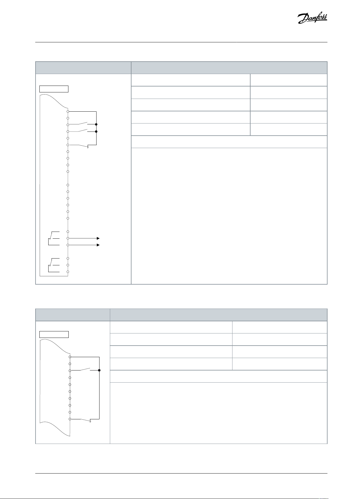
Table 17: Run/Stop Command without External Interlock
Basic I/O Configuration
AQ267037727118en-000101 / 130R030032 | Danfoss A/S © 2021.01
Parameter
+24 V
+24 V
D IN
D IN
D IN
COM
D IN
D IN
D IN
D IN
+10
V
A IN
A IN
COM
A OUT
COM
R1
R2
12
13
18
19
20
27
29
32
33
37
50
53
54
55
42
39
01
02
03
04
05
06
e30bb684.11
Drive
Function
Setting
Parameter 5-10 Terminal 18 Digital Input
[8] Start*
Parameter 5-11 Terminal 19 Digital Input
[52] Run permissive
Parameter 5-12 Terminal 27 Digital Input
[7] External interlock
Parameter 5-40 Function Relay
[167] Start command act.
*=Default value
Notes/comments:
D IN 37 is an option.
Parameter
+24 V
+24 V
D IN
D IN
D IN
COM
D IN
D IN
D IN
D IN
12
13
18
19
20
27
29
32
33
37
e30bb802.12
Drive
Function
Setting
Parameter 5-10 Terminal 18 Digital Input
[Start]*
Parameter 5-12 Terminal 27 Digital Input
[0] No operation
Parameter 5-19 Terminal 37 Safe Stop
[1] Safe Stop Alarm
*=Default value
Notes/comments:
If parameter 5-12 Terminal 27 Digital Input is set [0] No operation, a jumper wire to terminal 27 is
not needed.
D IN 37 is an option.
VLT® AutomationDrive FC 301/FC 302
Operating Guide
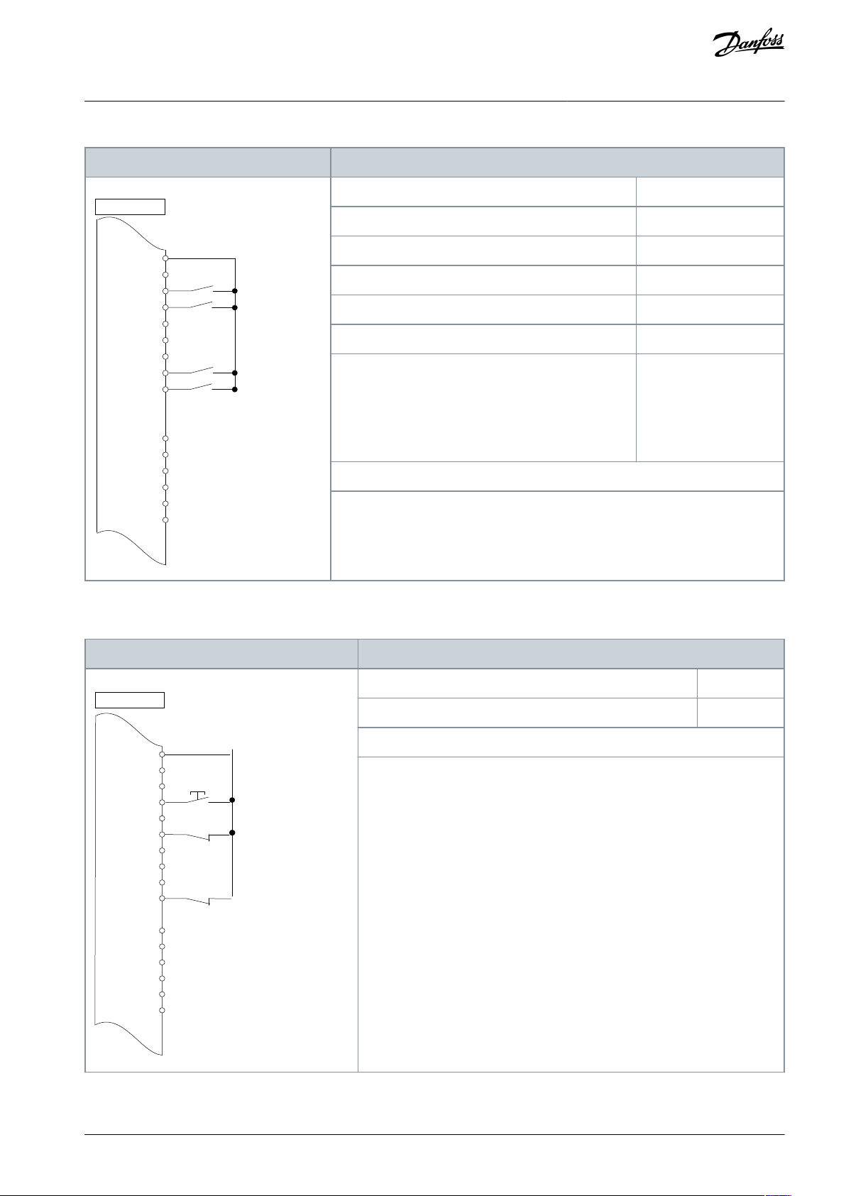
Table 18: Run Permissive
Basic I/O Configuration
6.1.7 Wiring Configuration: Start/Stop
Table 19: Start/Stop Command with Safe Torque Off Option
AQ267037727118en-000101 / 130R0300 | 33Danfoss A/S © 2021.01

e30bb805.13
Speed
Start/Stop (18)
Parameter
+24 V
+24 V
D IN
D IN
D IN
COM
D IN
D IN
D IN
D IN
+10
V
A IN
A IN
COM
A OUT
COM
12
13
18
19
20
27
29
32
33
37
50
53
54
55
42
39
e30bb803.10
Drive
Function
Setting
Parameter 5-10 Terminal 18 Digital Input
[9] Latched Start
Parameter 5-12 Terminal 27 Digital Input
[6] Stop Inverse
*=Default value
Notes/comments:
If parameter 5-12 Terminal 27 Digital Input is set [0] No operation, a jumper wire to terminal 27 is
not needed.
D IN 37 is an option.
Speed
e130bb806.11
Latched Start (18)
Stop Inverse (27)
VLT® AutomationDrive FC 301/FC 302
Operating Guide
Illustration 12: Start/Stop Command with Safe Torque Off
Table 20: Pulse Start/Stop
Basic I/O Configuration
Illustration 13: Latched Start/Stop Inverse
AQ267037727118en-000101 / 130R030034 | Danfoss A/S © 2021.01
Parameters
+24 V
+24 V
D IN
D IN
D IN
COM
D IN
D IN
D IN
+10
V
A IN
A IN
COM
A OUT
COM
12
13
18
19
20
27
29
32
33
50
53
54
55
42
39
e30bb934.11
Drive
Function
Setting
Parameter 5-10 Terminal 18 Digital Input
[8] Start
Parameter 5-11 Terminal 19 Digital Input
[10] Reversing*
Parameter 5-12 Terminal 27 Digital Input
[0] No operation
Parameter 5-14 Terminal 32 Digital Input
[16] Preset ref bit 0
Parameter 5-15 Terminal 33 Digital Input
[17] Preset ref bit 1
Parameter 3-10 Preset Reference
Preset ref. 0
Preset ref. 1
Preset ref. 2
Preset ref. 3
25%
50%
75%
100%
*=Default value
Notes/comments:
D IN 37 is an option.
Parameter
+24 V
+24 V
D IN
D IN
D IN
COM
D IN
D IN
D IN
D IN
+10
V
A IN
A IN
COM
A OUT
COM
12
13
18
19
20
27
29
32
33
37
50
53
54
55
42
39
e30bb928.12
Drive
Function
Setting
Parameter 5-11 Terminal 19 Digital Input
[1] Reset
*=Default value
Notes/comments:
D IN 37 is an option.
VLT® AutomationDrive FC 301/FC 302
Operating Guide
Table 21: Start/Stop with Reversing and 4 Preset Speeds
Basic I/O Configuration
6.1.8 Wiring Configuration: External Alarm Reset
Table 22: External Alarm Reset
AQ267037727118en-000101 / 130R0300 | 35Danfoss A/S © 2021.01

Parameter
+24 V
+24 V
D IN
D IN
D IN
COM
D IN
D IN
D IN
D IN
+10
V
A IN
A IN
COM
A OUT
COM
R1
R2
12
13
18
19
20
27
29
32
33
37
50
53
54
55
42
39
01
02
03
04
05
06
-
61
68
69
RS485
+
e30bb685.11
Drive
Function
Setting
Parameter 8-30 Protocol
FC*
Parameter 8-31 Address
1*
Parameter 8-32 Baud Rate
9600*
*=Default value
Notes/comments:
Select protocol, address, and baud rate in the above-mentioned parameters.
D IN 37 is an option.
VLT® AutomationDrive FC 301/FC 302
Operating Guide
6.1.9 Wiring Configuration: RS485
Table 23: RS485 Network Connection
Basic I/O Configuration
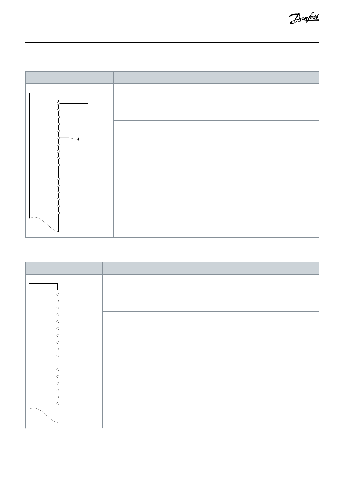
6.1.10 Wiring Configuration: Motor Thermistor
THERMISTOR INSULATION
Risk of personal injury or equipment damage.
To meet PELV insulation requirements, use only thermistors with reinforced or double insulation.
-
C A U T I O N
AQ267037727118en-000101 / 130R030036 | Danfoss A/S © 2021.01

Parameters
e30bb686.13
+24 V
+24 V
D IN
D IN
D IN
COM
D IN
D IN
D IN
+10
V
A IN
A IN
COM
A OUT
COM
12
13
18
19
20
27
29
32
33
50
53
54
55
42
39
A53
U - I
D IN
37
Drive
Function
Setting
Parameter 1-90 Motor Thermal Protection
[2] Thermistor trip
Parameter 1-93 Thermistor Source
[1] Analog input 53
* = Default value
If only a warning is required, set parameter 1-90 Motor Thermal Protection to [1] Thermistor warn-
ing.
D IN 37 is an option.
Parameters
+24 V
+24 V
D IN
D IN
D IN
COM
D IN
D IN
D IN
D IN
+10
V
A IN
A IN
COM
A OUT
COM
12
13
18
19
20
27
29
32
33
37
50
53
54
55
42
39
e30bd667.11
Drive
Function
Setting
Parameter 1-90 Motor Thermal Protection
100%*
* = Default value
VLT® AutomationDrive FC 301/FC 302
Operating Guide
Table 24: Motor Thermistor
Basic I/O Configuration
6.1.11 Wiring for Regen
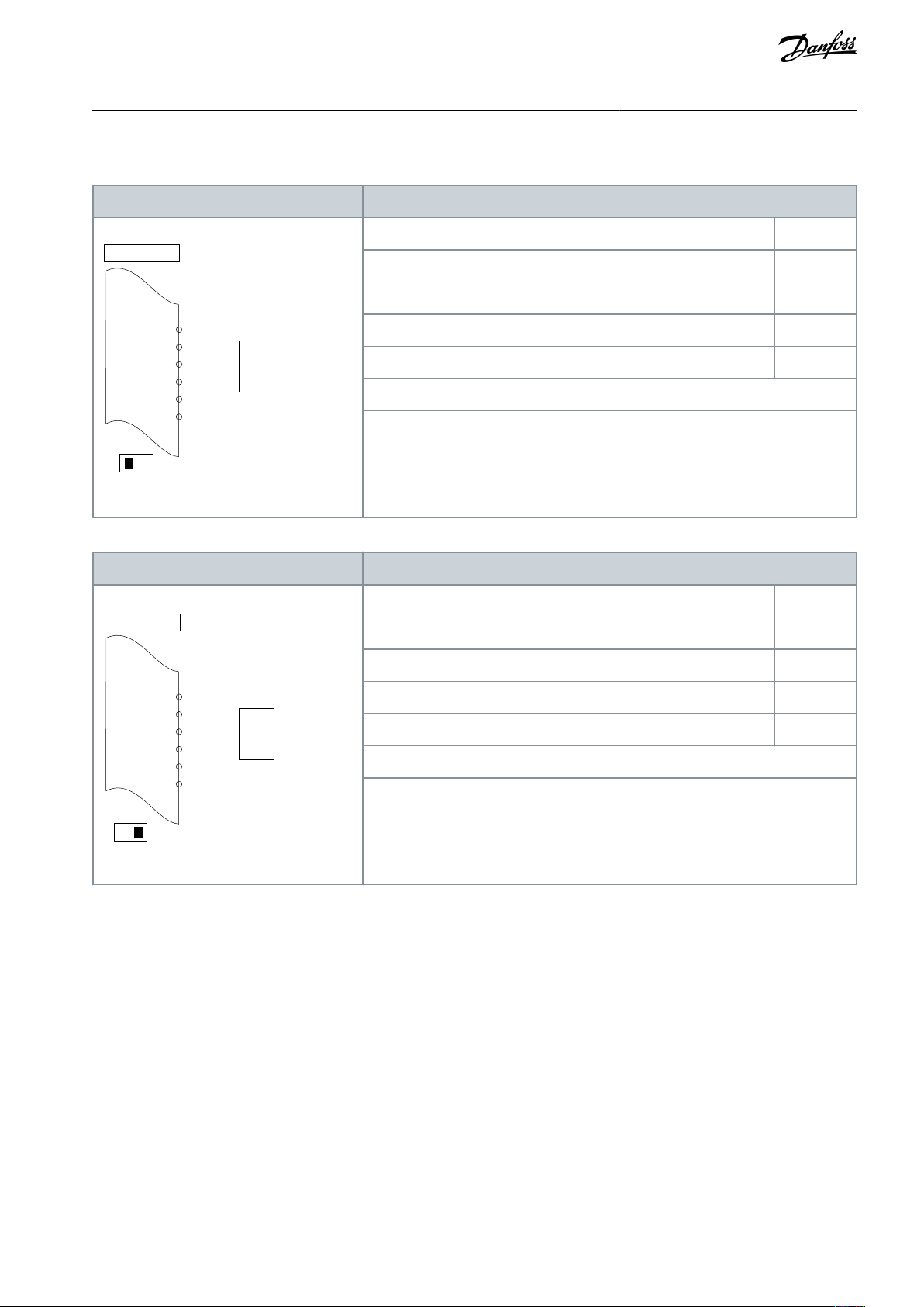
Table 25: Regen
AQ267037727118en-000101 / 130R0300 | 37Danfoss A/S © 2021.01

Parameters
To disable regen, decrease parameter 1-90 Motor Thermal Protection to 0%. If the application
uses motor brake power and regen is not enabled, the unit trips.
Parameters
+24 V
+24 V
D IN
D IN
D IN
COM
D IN
D IN
D IN
D IN
+10 V
A IN
A IN
COM
A OUT
COM
R 1 R 2
12
13
18
19
20
27
29
32
33
37
50
53
54
55
42
39
01
02
03
04
05
06
130BB839.10
Drive
Function
Setting
Parameter 4-30 Motor Feedback Loss Function
[1] Warning
Parameter 4-31 Motor Feedback Speed Error
100 RPM
Parameter 4-32 Motor Feedback Loss Timeout
5 s
Parameter 7-00 Speed PID Feedback Source
[2] MCB 102
Parameter 17-11 Resolution (PPR)
1024*
Parameter 13-00 SL Controller Mode
[1] On
Parameter 13-01 Start Event
[19] Warning
Parameter 13-02 Stop Event
[44] Reset key
Parameter 13-10 Comparator Operand
[21] Warning no.
Parameter 13-11 Comparator Operator
[1] ≈ (equal)*
Parameter 13-12 Comparator Value
90
Parameter 13-51 SL Controller Event
[22] Comparator 0
Parameter 13-52 SL Controller Action
[32] Set digital out A low
Parameter 5-40 Function Relay
[80] SL digital output A
*=Default value
Notes/comments:
If the limit in the feedback monitor is exceeded, warning 90, Feedback Mon. is issued. The SLC
monitors warning 90, Feedback Mon. and if the warning becomes true, relay 1 is triggered. External equipment may require service. If the feedback error goes below the limit again within
5 s, the drive continues and the warning disappears. Reset relay 1 by pressing [Reset] on the
LCP.
VLT® AutomationDrive FC 301/FC 302
Operating Guide
6.1.12 Wiring Configuration for a Relay Setup with Smart Logic Control
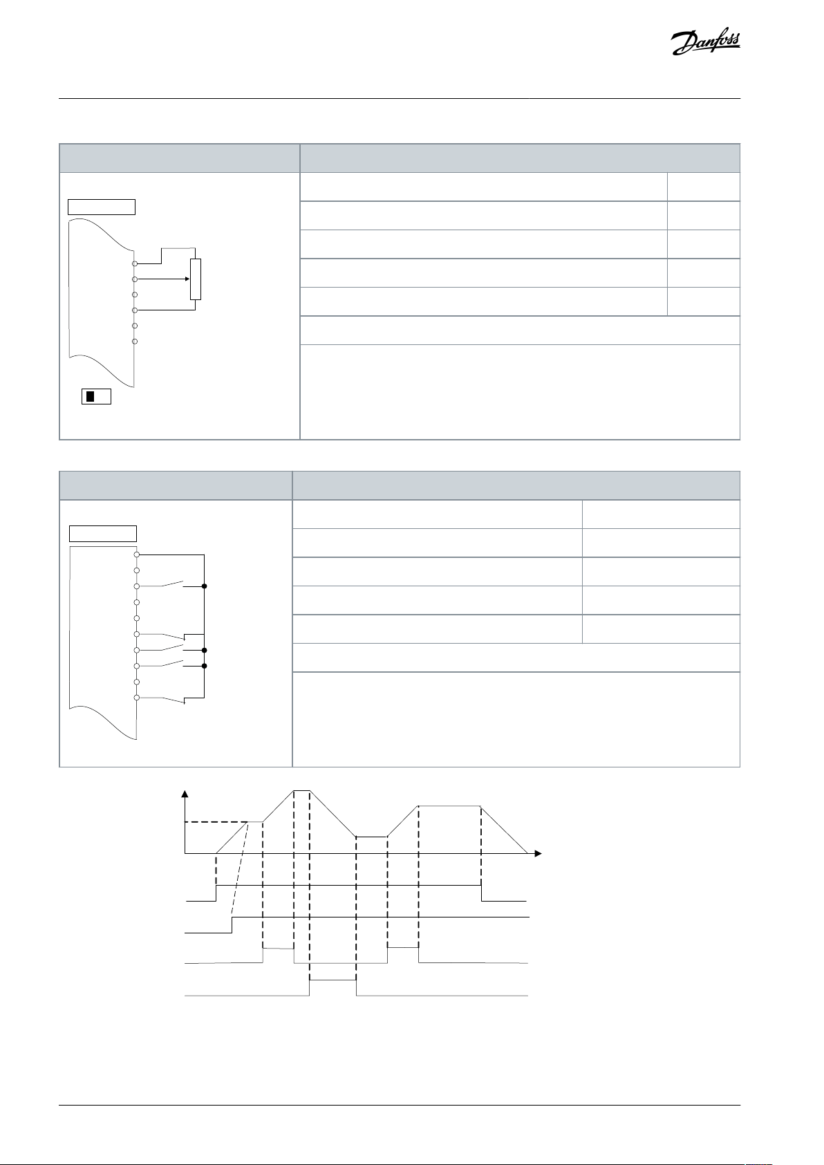
Table 26: Wiring Configuration for a Relay Setup with Smart Logic Control
Basic I/O Configuration
AQ267037727118en-000101 / 130R030038 | Danfoss A/S © 2021.01

Parameters
+24 V
+24 V
D IN
D IN
D IN
COM
D IN
D IN
D IN
D IN
+10
V
A IN
A IN
COM
A OUT
COM
R 1 R 2
12
13
18
19
20
27
29
32
33
37
50
53
54
55
42
39
01
02
03
04
05
06
e30bb841.10
Drive
Function
Setting
[32] Mech. brake ctrl.
Parameter 5-10 Terminal 18 Digital Input
[8] Start*
Parameter 5-11 Terminal 19 Digital Input
[11] Start reversing
Parameter 1-71 Start Delay
0.2
Parameter 1-72 Start Function
[5] VVC+/ FLUX Clockwise
Parameter 1-76 Start Current
I
m,n
Parameter 2-20 Release Brake Current
Application dependent
Parameter 2-21 Activate Brake Speed [RPM]
Half of nominal slip of the motor
* = Default value
–
e30bb842.11
2-21
2-21
1-71
1-71
1-76
Start (18)
Start
reversing (19)
Relay output
Open
Closed
Time
Current
Speed
VLT® AutomationDrive FC 301/FC 302
Operating Guide
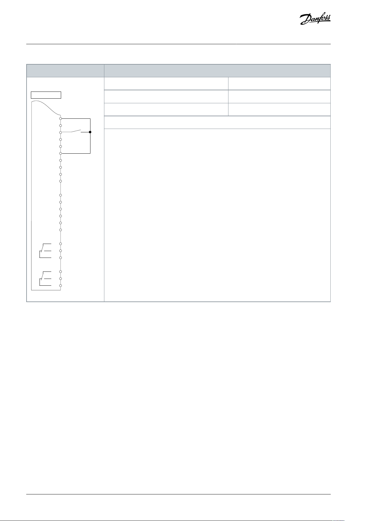
6.1.13 Wiring Configuration: Mechanical Brake Control
Table 27: Mechanical Brake Control
Basic I/O Configuration
Illustration 14: Mechanical Brake Control
6.1.14 Wiring Configuration for the Encoder
The direction of the encoder, identified by looking into the shaft end, is determined by which order the pulses enter the drive.
AQ267037727118en-000101 / 130R0300 | 39Danfoss A/S © 2021.01

B
A
B
A
1
e30ba646.10
2
VLT® AutomationDrive FC 301/FC 302
Operating Guide
••Clockwise (CW) direction means channel A is 90 electrical degrees before channel B.
Counterclockwise (CCW) direction means channel B is 90 electrical degrees before A.
Illustration 15: Determining Encoder Direction
Basic I/O Configuration
Maximum cable length is 5 m (16 ft.)
N O T I C E
AQ267037727118en-000101 / 130R030040 | Danfoss A/S © 2021.01

e30ba090.12
+24 V DC
A
B
GND
131218
37
32
271929
33
20
24 V or 10–30 V encoder
VLT® AutomationDrive FC 301/FC 302
Operating Guide
Basic I/O Configuration
Illustration 16: Wire Configuration for the Encoder
6.1.15 Wiring Configuration for Torque and Stop Limit
In applications with an external electro-mechanical brake, such as hoisting applications, it is possible to stop the drive via a standard
stop command and simultaneously activate the external electro-mechanical brake. Programming of these drive connections is
shown in Illustration 17.
If a stop command is active via terminal 18 and the drive is not at the torque limit, the motor ramps down to 0 Hz. If the drive is at
the torque limit and a stop command is activated, the system activates terminal 29 output (programmed to [27] Torque limit & stop).
The signal to terminal 27 changes from logic 1 to logic 0 and the motor starts to coast. This process ensures that the hoist stops
even if the drive itself cannot handle the required torque, for example due to excessive overload.
To program the stop and torque limit, connect to the following terminals:
•
Start/stop via terminal 18 (Parameter 5-10 Terminal 18 Digital Input [8] Start).
•
Quick stop via terminal 27 (Parameter 5-12 Terminal 27 Digital Input [2] Coasting Stop, Inverse).
•
Terminal 29 output (Parameter 5-02 Terminal 29 Mode [1] Terminal 29 Mode Output and parameter 5-31 Terminal 29 Digital Output
[27] Torque limit & stop).
•
Relay output [0] (Relay 1) (Parameter 5-40 Function Relay [32] Mechanical Brake Control).
AQ267037727118en-000101 / 130R0300 | 41Danfoss A/S © 2021.01

12
13
18
3732
271929
33
20
+24 V
P 5-10 [8]
P 5-12 [2]
P 5-02 [1]
P 5-31 [27]
GND
P 5-40 [0] [32]
Relay 1
01 02 03
-
+
e30ba194.11
External
24 V DC
Mechanical brake connection
Start
I
max
0.1 Amp
VLT® AutomationDrive FC 301/FC 302
Operating Guide
Basic I/O Configuration
Illustration 17: Wire Configuration for Torque and Stop Limit
AQ267037727118en-000101 / 130R030042 | Danfoss A/S © 2021.01

VLT® AutomationDrive FC 301/FC 302
Maintenance, Diagnostics, and
Operating Guide
Troubleshooting
7 Maintenance, Diagnostics, and Troubleshooting
7.1 Maintenance and Service
Under normal operating conditions and load profiles, the drive is maintenance-free throughout its designed lifetime. To prevent
breakdown, danger, and damage, examine the drive for loose terminal connections, excessive dust buildup, and so on, at regular
intervals. Replace worn or damaged parts with Danfoss authorized parts. For service and support, contact the local Danfoss supplier.
W A R N I N G
UNINTENDED START
When the drive is connected to the AC mains, DC supply, or load sharing, the motor may start at any time, causing risk of death,
serious injury, and equipment or property damage. The motor may start by activation of an external switch, a fieldbus command,
an input reference signal from the LCP or LOP, via remote operation using MCT 10 Set-up software, or after a cleared fault condi-
tion.
Press [Off] on the LCP before programming parameters.
-
Disconnect the drive from the mains whenever personal safety considerations make it necessary to avoid unintended motor
-
start.
Check that the drive, motor, and any driven equipment are in operational readiness.
-
7.2 Warning and Alarm Types
Warnings
A warning is issued when an alarm condition is impending, or when an abnormal operating condition is present and may result in
the drive issuing an alarm. A warning clears by itself when the abnormal condition ceases.
Alarms
An alarm indicates a fault that requires immediate attention. The fault always triggers a trip or a trip lock. Reset the system after an
alarm.
Trip
An alarm is issued when the drive is tripped, meaning that the drive suspends operation to prevent damage to the drive or system.
The motor coasts to a stop. The drive logic continues to operate and monitor the drive status. After the fault condition is remedied,
the drive can be reset. It is then ready to start operation again.
Trip lock
Input power is cycled. The motor coasts to a stop. The drive continues to monitor the drive status. Remove input power to the drive,
correct the cause of the fault, and reset the drive.
Resetting the drive after a trip/trip lock
A trip can be reset in any of 4 ways:
•
Press [Reset] on the LCP.
•
Digital reset input command.
•
Serial communication reset input command.
•
Auto reset.
AQ267037727118en-000101 / 130R0300 | 43Danfoss A/S © 2021.01
e30bp086.13
Status
0.0Hz 0.000kW 0.00A
0.0Hz
0
Earth Fault [A14]
Auto Remote Trip
1(1)
Back
Cancel
Info
OK
On
Alarm
Warn.
e30bb467.12
Warning indicator light
Alarm indicator light
Warning
On
Off
Alarm
Off
On (flashing)
Trip lock
On
On (flashing)
VLT® AutomationDrive FC 301/FC 302
Operating Guide
7.3 Warning and Alarm Displays
•
A warning is shown in the LCP along with the warning number.
•
An alarm flashes along with the alarm number.
Illustration 18: Alarm Example
In addition to the text and alarm code in the LCP there are 3 status indicator lights.
Maintenance, Diagnostics, and
Troubleshooting
Illustration 19: Status Indicator Lights
7.4 Descriptions of Warnings and Alarms
Depending on settings, FC 301/302 is able to give warnings or trigger alarms. In the Programming Guide for VLT® AutomationDrive
FC 301/302, a full list of all warnings and alarms can be found. Below, an extract of most common alarms and warnings can be
found.
The following warning and alarm information defines each warning or alarm condition, provides the probable cause for the condition, and entails a remedy or troubleshooting procedure.
7.4.1 WARNING 1, 10 Volts Low
Cause
The control card voltage is less than 10 V from terminal 50. Remove some of the load from terminal 50, as the 10 V supply is overloaded. Maximum 15 mA or minimum 590 Ω.
A short circuit in a connected potentiometer or incorrect wiring of the potentiometer can cause this condition.
AQ267037727118en-000101 / 130R030044 | Danfoss A/S © 2021.01

VLT® AutomationDrive FC 301/FC 302
Maintenance, Diagnostics, and
Operating Guide
Troubleshooting
•
Remove the wiring from terminal 50. If the warning clears, the problem is with the wiring. If the warning does not clear, replace
the control card.
Troubleshooting
7.4.2 WARNING/ALARM 2, Live Zero Error
Cause
This warning or alarm only appears if programmed in parameter 6-01 Live Zero Timeout Function. The signal on 1 of the analog inputs
is less than 50% of the minimum value programmed for that input. Broken wiring or a faulty device sending the signal can cause
this condition.
Troubleshooting
•
Check connections on all analog mains terminals.
-
Control card terminals 53 and 54 for signals, terminal 55 common.
-
VLT® General Purpose I/O MCB 101 terminals 11 and 12 for signals, terminal 10 common.
-
VLT® Analog I/O Option MCB 109 terminals 1, 3, and 5 for signals, terminals 2, 4, and 6 common.
•
Check that the drive programming and switch settings match the analog signal type.
•
Perform an input terminal signal test.
7.4.3 WARNING/ALARM 3, No Motor
Cause
No motor is connected to the output of the drive.
7.4.4 WARNING/ALARM 4, Mains Phase Loss
Cause
A phase is missing on the supply side, or the mains voltage imbalance is too high. This message also appears for a fault in the input
rectifier. Options are programmed in parameter 14-12 Function at Mains Imbalance.
Troubleshooting
Check the supply voltage and supply currents to the drive.
•
7.4.5 WARNING 5, DC Link Voltage High
Cause
The DC-link voltage (DC) is higher than the high-voltage warning limit. The limit depends on the drive voltage rating. The unit is still
active.
7.4.6 WARNING 6, DC Link Voltage Low
Cause
The DC-link voltage (DC) is lower than the low voltage warning limit. The limit depends on the drive voltage rating. The unit is still
active.
7.4.7 WARNING/ALARM 7, DC Overvoltage
Cause
If the DC-link voltage exceeds the limit, the drive trips after a certain time.
Troubleshooting
Extend the ramp time.
•
Change the ramp type.
•
•
Activate the functions in parameter 2-10 Brake Function.
•
Increase parameter 14-26 Trip Delay at Inverter Fault.
•
If the alarm/warning occurs during a power sag, use kinetic back-up (parameter 14-10 Mains Failure).
Connect a brake resistor.
•
7.4.8 WARNING/ALARM 8, DC Undervoltage
Cause
If the DC-link voltage drops below the undervoltage limit, the drive checks for 24 V DC back-up supply. If no 24 V DC back-up supply
is connected, the drive trips after a fixed time delay. The time delay varies with unit size.
AQ267037727118en-000101 / 130R0300 | 45Danfoss A/S © 2021.01

VLT® AutomationDrive FC 301/FC 302
Maintenance, Diagnostics, and
Operating Guide
Troubleshooting
•
Check that the supply voltage matches the drive voltage.
•
Perform an input voltage test.
•
Perform a soft-charge circuit test.
Troubleshooting
7.4.9 WARNING/ALARM 9, Inverter Overload
Cause
The drive has run with more than 100% overload for too long and is about to cut out. The counter for electronic thermal inverter
protection issues a warning at 98% and trips at 100% with an alarm. The drive cannot be reset until the counter is below 90%.
Troubleshooting
•
Compare the output current shown on the LCP with the drive rated current.
•
Compare the output current shown on the LCP with the measured motor current.
•
Show the thermal drive load on the LCP and monitor the value. When running above the drive continuous current rating, the
counter increases. When running below the drive continuos current rating, the counter decreases.
7.4.10 WARNING/ALARM 10, Motor Overload Temperature
Cause
According to the electronic thermal protection (ETR), the motor is too hot.
Select 1 of these options:
•
The drive issues a warning or an alarm when the counter is >90% if parameter 1-90 Motor Thermal Protection is set to warning
options.
•
The drive trips when the counter reaches 100% if parameter 1-90 Motor Thermal Protection is set to trip options.
The fault occurs when the motor runs with more than 100% overload for too long.
Troubleshooting
Check for motor overheating.
•
Check if the motor is mechanically overloaded.
•
•
Check that the motor current set in parameter 1-24 Motor Current is correct.
•
Ensure that the motor data in parameters 1-20 to 1-25 is set correctly.
•
If an external fan is in use, check that it is selected in parameter 1-91 Motor External Fan.
•
Running AMA in parameter 1-29 Automatic Motor Adaptation (AMA) tunes the drive to the motor more accurately and reduces
thermal loading.
7.4.11 WARNING/ALARM 11, Motor Thermistor Overtemp
Cause
The motor thermistor indicates that the motor temperature is too high.
Troubleshooting
Check for motor overheating.
•
Check that the thermistor is securely connected.
•
Check if the motor is mechanically overloaded.
•
When using terminal 53 or 54, check that the thermistor is connected correctly between either terminal 53 or 54 (analog voltage
•
input) and terminal 50 (+10 V supply). Also check that the terminal switch for 53 and 54 is set for voltage. Check that parameter
1-93 Thermistor Resource selects 53 or 54.
When using terminal 18, 19, 31, 32, or 33 (digital inputs), check that the thermistor is connected correctly between the digital
•
input terminal used (digital input PNP only) and terminal 50. Select the terminal to use in parameter 1-93 Thermistor Resource.
7.4.12 WARNING/ALARM 12, Torque Limit
Cause
The torque has exceeded the value in parameter 4-16 Torque Limit Motor Mode or the value in parameter 4-17 Torque Limit Generator
Mode. Parameter 14-25 Trip Delay at Torque Limit can change this warning from a warning-only condition to a warning followed by
an alarm.
AQ267037727118en-000101 / 130R030046 | Danfoss A/S © 2021.01

VLT® AutomationDrive FC 301/FC 302
Maintenance, Diagnostics, and
Operating Guide
Troubleshooting
•
If the motor torque limit is exceeded during ramp-up, extend the ramp-up time.
•
If the generator torque limit is exceeded during ramp-down time, extend the ramp-down time.
•
If torque limit occurs while running, increase the torque limit. Make sure that the system can operate safely at a higher torque.
•
Check the application for excessive current draw on the motor.
Troubleshooting
7.4.13 WARNING/ALARM 13, Overcurrent
Cause
The inverter peak current limit (approximately 200% of the rated current) is exceeded. The warning lasts approximately 1.5 s, then
the drive trips and issues an alarm. Shock loading or quick acceleration with high-inertia loads can cause this fault. If the acceleration during ramp-up is quick, the fault can also appear after kinetic back-up. If extended mechanical brake control is selected, a trip
can be reset externally.
Troubleshooting
•
Remove power and check if the motor shaft can be turned.
•
Check that the motor size matches the drive.
•
Check that the motor data is correct in parameters 1-20 to 1-25.
7.4.14 ALARM 14, Earth (Ground) Fault
Cause
There is current from the output phase to ground, either in the cable between the drive and the motor, or in the motor itself. The
current transducers detect the ground fault by measuring current going out from the drive and current going into the drive from
the motor. Ground fault is issued if the deviation of the 2 currents is too large. The current going out of the drive must be the same
as the current going into the drive.
Troubleshooting
•
Remove power to the drive and repair the ground fault.
•
Check for ground faults in the motor by measuring the resistance to ground of the motor cables and the motor with a megohmmeter.
•
Reset any potential individual offset in the 3 current transducers in the drive. Perform a manual initialization or perform a complete AMA. This method is most relevant after changing the power card.
7.4.15 ALARM 15, Hardware Mismatch
Cause
A fitted option is not operational with the present control card hardware or software.
Troubleshooting
Record the value of the following parameters and contact Danfoss.
•
Parameter 15-40 FC Type.
•
Parameter 15-41 Power Section.
•
Parameter 15-42 Voltage.
•
Parameter 15-43 Software Version.
•
Parameter 15-45 Actual Typecode String.
•
Parameter 15-49 SW ID Control Card.
•
Parameter 15-50 SW ID Power Card.
•
Parameter 15-60 Option Mounted.
•
Parameter 15-61 Option SW Version (for each option slot).
7.4.16 ALARM 16, Short Circuit
Cause
There is short-circuiting in the motor or motor wiring.
AQ267037727118en-000101 / 130R0300 | 47Danfoss A/S © 2021.01

VLT® AutomationDrive FC 301/FC 302
Maintenance, Diagnostics, and
Operating Guide
Troubleshooting
Troubleshooting
W A R N I N G
HAZARDOUS VOLTAGE
AC drives contain hazardous voltage when connected to the AC mains or connected on the DC terminals. Failure to perform
installation, start-up, and maintenance by skilled personnel can result in death or serious injury.
Only skilled personnel must perform installation, start-up, and maintenance.
-
•
Disconnect power before proceeding.
•
Remove the power to the drive and repair the short circuit.
7.4.17 WARNING/ALARM 17, Control Word Timeout
Cause
There is no communication to the drive. The warning is only active when parameter 8-04 Control Word Timeout Function is NOT set to
[0] Off.
If parameter 8-04 Control Word Timeout Function is set to [5] Stop and trip, a warning appears, and the drive ramps down to a stop
and shows an alarm.
Troubleshooting
Check the connections on the serial communication cable.
•
•
Increase parameter 8-03 Control Word Timeout Time.
Check the operation of the communication equipment.
•
Verify that proper EMC installation was performed.
•
7.4.18 WARNING/ALARM 20, Temp. Input Error
Cause
The temperature sensor is not connected.
7.4.19 WARNING/ALARM 21, Parameter Error
Cause
The parameter is out of range. The parameter number is shown in the display.
Troubleshooting
Set the affected parameter to a valid value.
•
7.4.20 WARNING/ALARM 22, Hoist Mechanical Brake
Cause
The value of this warning/alarm shows the type of warning/alarm.
0 = The torque reference was not reached before timeout (parameter 2-27 Torque Ramp Up Time).
1 = Expected brake feedback was not received before timeout (parameter 2-23 Activate Brake Delay, parameter 2-25 Brake Release
Time).
7.4.21 WARNING 23, Internal Fan Fault
Cause
The fan warning function is a protective function that checks if the fan is running/mounted. The fan warning can be disabled in
parameter 14-53 Fan Monitor ([0] Disabled).
For drives with DC fans, a feedback sensor is mounted in the fan. If the fan is commanded to run and there is no feedback from the
sensor, this alarm appears. For drives with AC fans, the voltage to the fan is monitored.
Troubleshooting
Check for proper fan operation.
•
Cycle power to the drive and check that the fan operates briefly at start-up.
•
Check the sensors on the control card.
•
AQ267037727118en-000101 / 130R030048 | Danfoss A/S © 2021.01

VLT® AutomationDrive FC 301/FC 302
Maintenance, Diagnostics, and
Operating Guide
Troubleshooting
7.4.22 WARNING 24, External Fan Fault
Cause
The fan warning function is a protective function that checks if the fan is running/mounted. The fan warning can be disabled in
parameter 14-53 Fan Monitor ([0] Disabled).
For drives with DC fans, a feedback sensor is mounted in the fan. If the fan is commanded to run and there is no feedback from the
sensor, this warning appears. For drives with AC fans, the voltage to the fan is monitored.
Troubleshooting
•
Check for proper fan operation.
•
Cycle power to the drive and check that the fan operates briefly at start-up.
•
Check the sensors on the heat sink.
7.4.23 WARNING 25, Brake Resistor Short Circuit
Cause
The brake resistor is monitored during operation. If a short circuit occurs, the brake function is disabled and the warning appears.
The drive is still operational, but without the brake function.
Troubleshooting
•
Remove the power to the drive and replace the brake resistor (refer to parameter 2-15 Brake Check).
7.4.24 WARNING/ALARM 26, Brake Resistor Power Limit
Cause
The power transmitted to the brake resistor is calculated as a mean value over the last 120 s of run time. The calculation is based on
the DC-link voltage and the brake resistor value set in parameter 2-16 AC Brake Max. Current. The warning is active when the dissipated braking power is higher than 90% of the brake resistor power. If option [2] Trip is selected in parameter 2-13 Brake Power Monitor-
ing, the drive trips when the dissipated braking power reaches 100%.
7.4.25 WARNING/ALARM 27, Brake Chopper Fault
Cause
The brake transistor is monitored during operation, and if a short circuit occurs, the brake function is disabled, and a warning is
issued. The drive is still operational, but since the brake transistor has short-circuited, substantial power is transmitted to the brake
resistor, even if it is inactive.
Troubleshooting
Remove the power to the drive and remove the brake resistor.
•
7.4.26 WARNING/ALARM 28, Brake Check Failed
Cause
The brake resistor is not connected or not working.
Troubleshooting
•
Check parameter 2-15 Brake Check.
7.4.27 ALARM 29, Heat Sink Temp
Cause
The maximum temperature of the heat sink is exceeded. The temperature fault is not reset until the temperature drops below a
defined heat sink temperature. The trip and reset points are different based on the drive power size.
Troubleshooting
Check for the following conditions:
The ambient temperature is too high.
•
The motor cables are too long.
•
Incorrect airflow clearance above and below the drive.
•
Blocked airflow around the drive.
•
Damaged heat sink fan.
•
Dirty heat sink.
•
AQ267037727118en-000101 / 130R0300 | 49Danfoss A/S © 2021.01

VLT® AutomationDrive FC 301/FC 302
Maintenance, Diagnostics, and
Operating Guide
Troubleshooting
7.4.28 ALARM 30, Motor Phase U Missing
Cause
Motor phase U between the drive and the motor is missing.
Troubleshooting
W A R N I N G
HAZARDOUS VOLTAGE
AC drives contain hazardous voltage when connected to the AC mains or connected on the DC terminals. Failure to perform
installation, start-up, and maintenance by skilled personnel can result in death or serious injury.
Only skilled personnel must perform installation, start-up, and maintenance.
-
•
Disconnect power before proceeding.
•
Remove the power from the drive and check motor phase U.
7.4.29 ALARM 31, Motor Phase V Missing
Cause
Motor phase V between the drive and the motor is missing.
Troubleshooting
W A R N I N G
HAZARDOUS VOLTAGE
AC drives contain hazardous voltage when connected to the AC mains or connected on the DC terminals. Failure to perform
installation, start-up, and maintenance by skilled personnel can result in death or serious injury.
Only skilled personnel must perform installation, start-up, and maintenance.
-
•
Disconnect power before proceeding.
•
Remove the power from the drive and check motor phase V.
7.4.30 ALARM 32, Motor Phase W Missing
Cause
Motor phase W between the drive and the motor is missing.
Troubleshooting
W A R N I N G
HAZARDOUS VOLTAGE
AC drives contain hazardous voltage when connected to the AC mains or connected on the DC terminals. Failure to perform
installation, start-up, and maintenance by skilled personnel can result in death or serious injury.
Only skilled personnel must perform installation, start-up, and maintenance.
-
•
Disconnect power before proceeding.
•
Remove the power from the drive and check motor phase W.
7.4.31 ALARM 33, Inrush Fault
Cause
Too many power-ups have occurred within a short time period.
Troubleshooting
•
Let the unit cool to operating temperature.
•
Check potential DC-link fault to ground.
7.4.32 WARNING/ALARM 34, Fieldbus Communication Fault
Cause
The fieldbus on the communication option card is not working.
AQ267037727118en-000101 / 130R030050 | Danfoss A/S © 2021.01

Number
Text0The serial port cannot be initialized. Contact the Danfoss supplier or Danfoss service department.
256–258
The power EEPROM data is defective or too old. Replace the power card.
512–519
Internal fault. Contact the Danfoss supplier or Danfoss service department.
783
Parameter value outside of minimum/maximum limits.
1024–1284
Internal fault. Contact the Danfoss supplier or Danfoss service department.
1299
The option software in slot A is too old.
1300
The option software in slot B is too old.
1302
The option software in slot C1 is too old.
1315
The option software in slot A is not supported/allowed.
1316
The option software in slot B is not supported/ allowed.
1318
The option software in slot C1 is not supported/ allowed.
1379–2819
Internal fault. Contact the Danfoss supplier or Danfoss service department.
1792
Hardware reset of digital signal processor.
1793
Motor-derived parameters not transferred correctly to the digital signal processor.
1794
Power data not transferred correctly at power-up to the digital signal processor.
1795
The digital signal processor has received too many unknown SPI telegrams. The AC drive also uses this fault code if
the MCO does not power up correctly. This situation can occur due to poor EMC protection or improper grounding.
VLT® AutomationDrive FC 301/FC 302
Maintenance, Diagnostics, and
Operating Guide
Troubleshooting
7.4.33 WARNING/ALARM 35, Option Fault
Cause
An option alarm is received. The alarm is option-specific. The most likely cause is a power-up or a communication fault.
7.4.34 WARNING/ALARM 36, Mains Failure
Cause
This warning/alarm is only active if the supply voltage to the drive is lost and parameter 14-10 Mains Failure is not set to [0] No Func-
tion.
Troubleshooting
Check the fuses to the drive and mains supply to the unit.
•
7.4.35 ALARM 37, Phase Imbalance
Cause
There is a current imbalance between the power units.
7.4.36 ALARM 38, Internal Fault
Cause
When an internal fault occurs, a code number defined in
Troubleshooting
•
Cycle power.
•
Check that the option is properly installed.
•
Check for loose or missing wiring.
It may be necessary to contact the Danfoss supplier or service department. Note the code number for further troubleshooting directions.
Table 28 is shown.
Table 28: Internal Fault Codes
AQ267037727118en-000101 / 130R0300 | 51Danfoss A/S © 2021.01

Number
Text
1796
RAM copy error.
2561
Replace the control card.
2820
LCP stack overflow.
2821
Serial port overflow.
2822
USB port overflow.
3072–5122
Parameter value is outside its limits.
5123
Option in slot A: Hardware incompatible with the control board hardware.
5124
Option in slot B: Hardware incompatible with the control board hardware.
5125
Option in slot C0: Hardware incompatible with the control board hardware.
5126
Option in slot C1: Hardware incompatible with the control board hardware.
5376– 6231
Internal fault. Contact the Danfoss supplier or Danfoss service department.
VLT® AutomationDrive FC 301/FC 302
Operating Guide
Maintenance, Diagnostics, and
Troubleshooting
7.4.37 ALARM 39, Heat Sink Sensor
Cause
No feedback from the heat sink temperature sensor.
The signal from the IGBT thermal sensor is not available on the power card. The problem could be on the power card, on the gate-
drive card, or on the ribboncable between the power card and the gatedrive card.
7.4.38 WARNING 40, Overload of Digital Output Terminal 27
Troubleshooting
•
Check the load connected to terminal 27 or remove the short-circuit connection.
•
Check parameter 5-00 Digital I/O Mode and parameter 5-01 Terminal 27 Mode.
7.4.39 WARNING 41, Overload of Digital Output Terminal 29
Troubleshooting
•
Check the load connected to terminal 29 or remove the short-circuit connection.
•
Check parameter 5-00 Digital I/O Mode and parameter 5-02 Terminal 29 Mode.
7.4.40 WARNING 42, Ovrld X30/6-7
Troubleshooting
For terminal X30/6:
Check the load connected to the terminal, or remove the short-circuit connection.
•
•
Check parameter 5-32 Term X30/6 Digi out (MCB 101) (VLT® General Purpose I/O MCB 101).
For terminal X30/7:
Check the load connected to the terminal, or remove the short-circuit connection.
•
•
Check parameter 5-33 Term X30/7 Digi Out (MCB 101) (VLT® General Purpose I/O MCB 101).
7.4.41 ALARM 43, Ext. Supply
Cause
VLT® Extended Relay Option MCB 113 is mounted without 24 V DC.
Troubleshooting
Choose 1 of the following:
AQ267037727118en-000101 / 130R030052 | Danfoss A/S © 2021.01

VLT® AutomationDrive FC 301/FC 302
Maintenance, Diagnostics, and
Operating Guide
•
Connect a 24 V DC external supply.
•
Specify that no external supply is used via parameter 14-80 Option Supplied by External 24VDC, [0] No. A change in parameter
14-80 Option Supplied by External 24VDC requires a power cycle.
Troubleshooting
7.4.42 ALARM 45, Earth Fault 2
Cause
Ground fault.
Troubleshooting
Check for proper grounding and loose connections.
•
Check for proper wire size.
•
Check the motor cables for short circuits or leakage currents.
•
7.4.43 ALARM 46, Power Card Supply
Cause
The supply on the power card is out of range. Another reason can be a defective heat sink fan.
There are 3 supplies generated by the switch mode supply (SMPS) on the power card:
24 V.
•
5 V.
•
±18 V.
•
When powered with VLT® 24 V DC Supply MCB 107, only 24 V and 5 V supplies are monitored. When powered with 3-phase mains
voltage, all 3 supplies are monitored.
Troubleshooting
Check for a defective power card.
•
Check for a defective control card.
•
Check for a defective option card.
•
If a 24 V DC supply is used, verify proper supply power.
•
Check for a defective heat sink fan.
•
7.4.44 WARNING 47, 24 V Supply Low
Cause
The supply on the power card is out of range.
There are 3 supplies generated by the switch mode supply (SMPS) on the power card:
24 V
•
5 V
•
±18 V
•
Troubleshooting
Check for a defective power card.
•
7.4.45 WARNING 48, 1.8 V Supply Low
Cause
The 1.8 V DC supply used on the control card is outside of the allowed limits. The supply is measured on the control card.
Troubleshooting
Check for a defective control card.
•
If an option card is present, check for overvoltage.
•
7.4.46 WARNING 49, Speed Limit
Cause
The warning is shown when the speed is outside of the specified range in parameter 4-11 Motor Speed Low Limit [RPM] and parame-
ter 4-13 Motor Speed High Limit [RPM]. When the speed is below the specified limit in parameter 1-86 Trip Speed Low [RPM] (except
when starting or stopping), the drive trips.
AQ267037727118en-000101 / 130R0300 | 53Danfoss A/S © 2021.01

VLT® AutomationDrive FC 301/FC 302
Operating Guide
7.4.47 ALARM 50, AMA Calibration Failed
Cause
A calibration error has occurred.
Troubleshooting
•
Contact the Danfoss supplier or Danfoss service department.
7.4.48 ALARM 51, AMA Check Unom and Inom
Cause
The settings for motor voltage, motor current, and motor power are wrong.
Troubleshooting
•
Check settings in parameters 1-20 to 1-25.
7.4.49 ALARM 52, AMA Low Inom
Cause
The motor current is too low.
Troubleshooting
•
Check the settings in parameter 1-24 Motor Current.
Maintenance, Diagnostics, and
Troubleshooting
7.4.50 ALARM 53, AMA Motor Too Big
Cause
The motor is too big for the AMA to operate.
Troubleshooting
•
Check the settings in parameter group 1-2* Motor Data.
7.4.51 ALARM 54, AMA Motor Too Small
Cause
The motor is too small for the AMA to operate.
Troubleshooting
•
Check the settings in parameter group 1-2* Motor Data.
7.4.52 ALARM 55, AMA Parameter Out of Range
Cause
The AMA cannot run because the paramenter values of the motor are out of the acceptable range.
Troubleshooting
•
Check the settings in parameter group 1-2* Motor Data.
7.4.53 ALARM 56, AMA Interrupted by User
Cause
The AMA is manually interrupted.
Troubleshooting
Re-run th AMA calibration.
•
7.4.54 ALARM 57, AMA Internal Fault
Troubleshooting
Try to restart the AMA. Repeated restarts can overheat the motor.
7.4.55 ALARM 58, AMA Internal Fault
Troubleshooting
Contact the Danfoss supplier.
7.4.56 WARNING 59, Current Limit
Cause
The current is higher than the value in parameter 4-18 Current Limit.
AQ267037727118en-000101 / 130R030054 | Danfoss A/S © 2021.01

VLT® AutomationDrive FC 301/FC 302
Maintenance, Diagnostics, and
Operating Guide
Troubleshooting
•
Ensure that the motor data in parameters 1-20 to 1-25 is set correctly.
•
Increase the current limit if necessary. Ensure that the system can operate safely at a higher limit.
Troubleshooting
7.4.57 WARNING 60, External Interlock
Cause
A digital input signal indicates a fault condition external to the drive. An external interlock has commanded the drive to trip.
Troubleshooting
•
Clear the external fault condition.
•
To resume normal operation, apply 24 V DC to the terminal programmed for external interlock.
•
Reset the drive.
7.4.58 WARNING/ALARM 61, Feedback Error
Cause
An error between calculated speed and speed measurement from feedback device.
Troubleshooting
•
Check the settings for warning/alarm/disabling in parameter 4-30 Motor Feedback Loss Function.
•
Set the tolerable error in parameter 4-31 Motor Feedback Speed Error.
•
Set the tolerable feedback loss time in parameter 4-32 Motor Feedback Loss Timeout.
7.4.59 WARNING 62, Output Frequency at Maximum Limit
Cause
The output frequency has reached the value set in parameter 4-19 Max Output Frequency.
Troubleshooting
Check the application for possible causes.
•
Increase the output frequency limit. Be sure that the system can operate safely at a higher output frequency.
•
The warning clears when the output drops below the maximum limit.
7.4.60 ALARM 63, Mechanical Brake Low
Cause
The actual motor current has not exceeded the release brake current within the start delay time window.
7.4.61 WARNING 64, Voltage Limit
Cause
The load and speed combination demands a motor voltage higher than the actual DC-link voltage.
7.4.62 WARNING/ALARM 65, Control Card Overtemperature
Cause
The cutout temperature of the control card has exceeded the upper limit.
Troubleshooting
Check that the ambient operating temperature is within the limits.
•
Check for clogged filters.
•
Check fan operation.
•
Check the control card.
•
7.4.63 WARNING 66, Heat Sink Temperature Low
Cause
The drive is too cold to operate. This warning is based on the temperature sensor in the IGBT module.
AQ267037727118en-000101 / 130R0300 | 55Danfoss A/S © 2021.01

VLT® AutomationDrive FC 301/FC 302
Maintenance, Diagnostics, and
Operating Guide
Troubleshooting
•
Increase the ambient temperature of the unit.
•
Supply a trickle amount of current to the drive whenever the motor is stopped by setting parameter 2-00 DC Hold/Preheat Cur-
rent to 5% and parameter 1-80 Function at Stop.
Troubleshooting
7.4.64 ALARM 67, Option Module Configuration has Changed
Cause
One or more options have either been added or removed since the last power-down.
Troubleshooting
Check that the configuration change is intentional and reset the unit.
•
7.4.65 ALARM 68, Safe Stop Activated
Cause
Safe Torque Off (STO) has been activated.
Troubleshooting
To resume normal operation, apply 24 V DC to terminal 37, then send a reset signal (via bus, digital, or by pressing [Reset]).
•
7.4.66 ALARM 69, Power Card Temperature
Cause
The temperature sensor on the power card is either too hot or too cold.
Troubleshooting
Check that the ambient operating temperature is within the limits.
•
Check for clogged filters.
•
Check fan operation.
•
Check the power card.
•
7.4.67 ALARM 70, Illegal FC Configuration
Cause
The control card and power card are incompatible.
Troubleshooting
To check compatibility, contact the Danfoss supplier with the type code from the unit nameplate and the part numbers on the
•
cards.
7.4.68 ALARM 71, PTC 1 Safe Stop
Cause
Because the motor is too warm, the VLT® PTC Thermistor Card MCB 112 activated the Safe Torque Off (STO).
Troubleshooting
•
Once the motor temperature reaches an acceptable level and the digital input from MCB 112 is deactivated, perform 1 of the
following:
-
Send a reset signal via bus or digital I/O.
-
Press [Reset].
7.4.69 ALARM 72, Dangerous Failure
Cause
Safe Torque Off (STO) with trip lock.
Troubleshooting
An unexpected combination of STO commands has occurred:
•
VLT® PTC Thermistor Card MCB 112 enables X44/10, but STO is not enabled.
•
MCB 112 is the only device using STO (specified through selection [4] PTC 1 alarm or [5] PTC 12 warning in parameter 5-19 Termi-
nal 37 Safe Stop). STO is activated, but X44/10 is not activated.
AQ267037727118en-000101 / 130R030056 | Danfoss A/S © 2021.01

VLT® AutomationDrive FC 301/FC 302
Maintenance, Diagnostics, and
Operating Guide
Troubleshooting
7.4.70 WARNING 73, Safe Stop Auto Restart
Cause
STO activated.
Troubleshooting
•
With automatic restart enabled, the motor can start when the fault is cleared.
7.4.71 ALARM 74, PTC Thermistor
Cause
The PTC is not working. Alarm is related to VLT® PTC Thermistor Card MCB 112.
7.4.72 ALARM 75, Illegal Profile Sel.
Cause
There was an attempt to write the parameter value while the motor was running.
Troubleshooting
•
Stop the motor before writing the MCO profile to parameter 8-10 Control Word Profile.
7.4.73 WARNING 77, Reduced Power Mode
Cause
The drive is operating in reduced power mode (less than allowed number of inverter sections). The warning is generated on power
cycle when the drive is set to run with fewer inverters and remains on.
7.4.74 ALARM 78, Tracking Error
Cause
The difference between setpoint value and actual value exceeds the value in parameter 4-35 Tracking Error.
Troubleshooting
•
Disable the function or select an alarm/warning in parameter 4-34 Tracking Error Function.
•
Investigate the mechanics around the load and motor. Check feedback connections from motor encoder to drive.
•
Select motor feedback function in parameter 4-30 Motor Feedback Loss Function.
•
Adjust the tracking error band in parameter 4-35 Tracking Error and parameter 4-37 Tracking Error Ramping.
7.4.75 ALARM 79, Illegal Power Section Configuration
Cause
The scaling card has an incorrect part number or is not installed. The MK102 connector on the power card could not be installed.
7.4.76 ALARM 80, Drive Initialized to Default Value
Cause
Parameter settings are initialized to default settings after a manual reset.
Troubleshooting
To clear the alarm, reset the unit.
7.4.77 ALARM 81, CSIV Corrupt
Cause
The CSIV file has syntax errors.
7.4.78 ALARM 82, CSIV Parameter Error
Cause
CSIV failed to initialize a parameter.
7.4.79 ALARM 83, Illegal Option Combination
Cause
The mounted options are incompatible.
AQ267037727118en-000101 / 130R0300 | 57Danfoss A/S © 2021.01

VLT® AutomationDrive FC 301/FC 302
Maintenance, Diagnostics, and
Operating Guide
Troubleshooting
7.4.80 ALARM 84, No Safety Option
Cause
The safety option was removed without applying a general reset.
Troubleshooting
Reconnect the safety option.
7.4.81 ALARM 88, Option Detection
Cause
A change in the option layout is detected. Parameter 14-89 Option Detection is set to [0] Frozen configuration and the option layout
has been changed.
Troubleshooting
•
To apply the change, enable option layout changes in parameter 14-89 Option Detection.
Alternatively, restore the correct option configuration.
•
7.4.82 WARNING 89, Mechanical Brake Sliding
Cause
The hoist brake monitor detects a motor speed exceeding 10 RPM.
7.4.83 ALARM 90, Feedback Monitor
Troubleshooting
Check the connection to the encoder/resolver option and, if necessary, replace the VLT® Encoder Input MCB 102 or VLT® Resolv-
•
er Input MCB 103.
7.4.84 ALARM 91, Analog Input 54 Wrong Settings
Troubleshooting
Set switch S202 in position OFF (voltage input) when a KTY sensor is connected to analog input terminal 54.
•
7.4.85 ALARM 99, Locked Rotor
Cause
The rotor is blocked.
Troubleshooting
Check if the motor shaft is locked.
•
•
Check if the start current triggers the current limit set in parameter 4-18 Current Limit.
•
Check if it increases the value in parameter 30-23 Locked Rotor Detection Time [s].
7.4.86 WARNING/ALARM 104, Mixing Fan Fault
Cause
The fan is not operating. The fan monitor checks that the fan is spinning at power-up or whenever the mixing fan is turned on. The
mixing fan fault can be configured as a warning or an alarm in parameter 14-53 Fan Monitor.
Troubleshooting
Cycle power to the drive to determine if the warning/alarm returns.
•
7.4.87 WARNING/ALARM 122, Mot. Rotat. Unexp.
Cause
The drive performs a function that requires the motor to be at standstill, for example DC hold for PM motors.
7.4.88 WARNING 163, ATEX ETR Cur.Lim.Warning
Cause
The drive has run above the characteristic curve for more than 50 s. The warning is activated at 83% and deactivated at 85% of the
allowed thermal overload.
7.4.89 ALARM 164, ATEX ETR Cur.Lim.Alarm
Cause
Running above the characteristic curve for more than 60 s within a period of 600 s activates the alarm, and the drive trips.
AQ267037727118en-000101 / 130R030058 | Danfoss A/S © 2021.01

VLT® AutomationDrive FC 301/FC 302
Maintenance, Diagnostics, and
Operating Guide
Troubleshooting
7.4.90 WARNING 165, ATEX ETR Freq.Lim.Warning
Cause
The drive has run for more than 50 s below the allowed minimum frequency (parameter 1-98 ATEX ETR Interpol. Points Freq.).
7.4.91 ALARM 166, ATEX ETR Freq.Lim.Alarm
Cause
The drive has run for more than 60 s (in a period of 600 s) below the allowed minimum frequency (parameter 1-98 ATEX ETR Interpol.
Points. Freq.).
7.4.92 WARNING 250, New Spare Part
Cause
A component in the drive system has been replaced.
Troubleshooting
Reset the drive system to restore normal operation.
•
7.4.93 WARNING 251, New Typecode
Cause
The power card or other components have been replaced, and the typecode has changed.
AQ267037727118en-000101 / 130R0300 | 59Danfoss A/S © 2021.01

Type designation
PK25
PK37
PK55
PK75
P1K1
P1K5
P2K2
P3K0
P3K7
Typical shaft output [kW/
(hp)], high overload
0.25 (0.34)
0.37 (0.5)
0.55 (0.75)
0.75 (1.0)
1.1 (1.5)
1.5 (2.0)
2.2 (3.0)
3.0 (4.0)
3.7 (5.0)
Enclosure protection rating
IP20 (FC 301 only)
A1A1A1A1A1A1–––
Enclosure protection rating
IP20, IP21
A2A2A2A2A2A2A2A3A3
Enclosure protection rating
IP55, IP66
A4/A5
A4/A5
A4/A5
A4/A5
A4/A5
A4/A5
A4/A5
A5
A5
Output current
Continuous (200–240 V) [A]
1.8
2.4
3.5
4.6
6.6
7.5
10.6
12.5
16.7
Intermittent (200–240 V) [A]
2.9
3.8
5.6
7.4
10.612172026.7
Continuous kVA (208 V)
[kVA]
0.65
0.86
1.26
1.66
2.38
2.70
3.82
4.50
6.0
Maximum input current
Continuous (200–240 V) [A]
1.6
2.2
3.2
4.1
5.9
6.8
9.5
11.315Intermittent (200–240 V) [A]
2.6
3.5
5.1
6.6
9.4
10.9
15.2
18.1
24
Additional specifications
Estimated power loss at rated maximum load [W]
(1)
212942546382116
155
185
Efficiency
(2)
0.94
0.94
0.95
0.95
0.96
0.96
0.96
0.96
0.96
Type designation
P5K5
P7K5
P11K
High/normal overload
(1)
HONOHONOHONOTypical shaft output [kW/(hp)]
5.5 (7.5)
7.5 (10)
7.5 (10)
11 (15)
11 (15)
15 (20)
Enclosure protection rating IP20
B3B3B4
Enclosure protection rating IP21, IP55, IP66
B1B1B2
Output current
Continuous (200–240 V) [A]
24.2
30.8
30.8
46.2
46.2
59.4
VLT® AutomationDrive FC 301/FC 302
Operating Guide
8 Specifications
8.1 Electrical Data
8.1.1 Mains Supply 200–240 V
Table 29: Mains Supply 200–240 V, PK25–P3K7
Specifications
1
Applies for dimensioning of drive cooling. If the switching frequency is higher than the default setting, the power losses may increase. LCP and
typical control card power consumptions are included. For power loss data according to EN 50598-2, refer to Danfoss
2
Efficiency measured at nominal current. For energy efficiency class, see
mart website.
Table 30: Mains Supply 200–240 V, P5K5–P11K
MyDrive® ecoSmart website.
8.4 Ambient Conditions. For part load losses, see Danfoss MyDrive® ecoS-
AQ267037727118en-000101 / 130R030060 | Danfoss A/S © 2021.01

Type designation
P5K5
P7K5
P11K
Intermittent (60 s overload) (200–240 V [A]
38.7
33.9
49.3
50.8
73.9
65.3
Continuous kVA (208 V) [kVA]
8.7
11.1
11.1
16.6
16.6
21.4
Maximum input current
Continuous (200–240 V) [A]
222828424254Intermittent (60 s overload) (200–240 V [A]
35.2
30.8
44.8
46.2
67.2
59.4
Additional specifications
Estimated power loss at rated maximum load [W]
(2)
239
310
371
514
463
602
Efficiency
(3)
0.96
0.96
0.96
Type designation
P15K
P18K
P22K
P30K
P37K
Hign/normal overload
(1)
HONOHONOHONOHONOHONOTypical shaft output [kW/(hp)]
15 (20)
18.5 (25)
18.5 (25)
22 (30)
22 (30)
30 (40)
30 (40)
37 (50)
37 (50)
45 (60)
Enclosure protection rating
IP20
B4C3C3C4C4
Enclosure protection rating
IP21, IP55, IP66
C1C1C1C2C2
Output current
Continuous (200–240 V) [A]
59.4
74.8
74.88888
115
115
143
143
170
Intermittent (60 s overload)
(200–240 V) [A]
89.1
82.3
112
96.8
132
127
173
157
215
187
Continuous kVA (208 V) [kVA]
21.4
26.9
26.9
31.7
31.7
41.4
41.4
51.5
51.5
61.2
Maximum input current
Continuous (200–240 V) [A]
5468688080
104
104
130
130
154
Intermittent (60 s overload)
(200–240 V) [A]
81
74.8
10288120
114
156
143
195
169
Additional specifications
Estimated power loss at rated
maximum load [W]
(2)
624
737
740
845
874
1140
1143
1353
1400
1636
VLT® AutomationDrive FC 301/FC 302
Operating Guide
1
High overload=150% or 160% torque for a duration of 60 s. Normal overload=110% torque for a duration of 60 s.
2
Applies for dimensioning of drive cooling. If the switching frequency is higher than the default setting, the power losses may increase. LCP and
typical control card power consumptions are included. For power loss data according to EN 50598-2, refer to Danfoss
3
Efficiency measured at nominal current. For energy efficiency class, see
mart website.
8.4 Ambient Conditions. For part load losses, see Danfoss MyDrive® ecoS-
MyDrive® ecoSmart website.
Specifications
Table 31: Mains Supply 200–240 V, P15K–P37K
AQ267037727118en-000101 / 130R0300 | 61Danfoss A/S © 2021.01

Type designation
P15K
P18K
P22K
P30K
P37K
Efficiency
(3)
0.96
0.97
0.97
0.97
0.97
Type designation
PK37
PK55
PK75
P1K1
P1K5
P2K2
P3K0
P4K0
P5K5
P7K7
Typical shaft output
[kW/(hp)], high overload
0.37 (0.5)
0.55
(0.75)
0.75 (1.0)
1.1 (1.5)
1.5 (2.0)
2.2 (3.0)
3.0 (4.0)
4.0 (5.0)
5.5 (7.5)
7.5 (10)
Enclosure protection
rating IP20 (FC 301
only)
A1A1A1A1A1––––
–
Enclosure protection
rating IP20, IP21
A2A2A2A2A2A2A2A2A3A3Enclosure protection
rating IP55, IP66
A4/A5
A4/A5
A4/A5
A4/A5
A4/A5
A4/A5
A4/A5
A4/A5
A5
A5
Output current high overload 160% for 1 minute
Shaft output [kW/
(hp)]
0.37 (0.5)
0.55
(0.75)
0.75 (1.0)
1.1 (1.5)
1.5 (2.0)
2.2 (3.0)
3.0 (4.0)
4.0 (5.0)
5.5 (7.5)
7.5 (10)
Continuous (380–
440 V) [A]
1.3
1.8
2.4
3.0
4.1
5.6
7.2101316Intermittent (380–
440 V) [A]
2.1
2.9
3.8
4.8
6.6
9.0
11.51620.8
25.6
Continuous (441–
500 V) [A]
1.2
1.6
2.1
2.7
3.4
4.8
6.3
8.21114.5
Intermittent (441–
500 V) [A]
1.9
2.6
3.4
4.3
5.4
7.7
10.1
13.1
17.6
23.2
Continuous kVA
(400 V) [kVA]
0.9
1.3
1.7
2.1
2.8
3.9
5.0
6.9
9.011Continuous kVA
(460 V) [kVA]
0.9
1.3
1.7
2.4
2.7
3.8
5.0
6.5
8.8
11.6
Maximum input current
Continuous (380–
440 V) [A]
1.2
1.6
2.2
2.7
3.7
5.0
6.5
9.0
11.7
14.4
Intermittent (380–
440 V) [A]
1.9
2.6
3.5
4.3
5.9
8.0
10.4
14.4
18.723Continuous (441–
500 V) [A]
1.0
1.4
1.9
2.7
3.1
4.3
5.7
7.4
9.9
13
VLT® AutomationDrive FC 301/FC 302
Operating Guide
1
High overload=150% or 160% torque for a duration of 60 s. Normal overload=110% torque for a duration of 60 s.
2
Applies for dimensioning of drive cooling. If the switching frequency is higher than the default setting, the power losses may increase. LCP and
typical control card power consumptions are included. For power loss data according to EN 50598-2, refer to Danfoss
3
Efficiency measured at nominal current. For energy efficiency class, see
mart website.
8.4 Ambient Conditions. For part load losses, see Danfoss MyDrive® ecoS-
MyDrive® ecoSmart website.
Specifications
8.1.2 Mains Supply 380–500 V
Table 32: Mains Supply 380–500 V (FC 302), 380–480 V (FC 301), PK37–P7K5
AQ267037727118en-000101 / 130R030062 | Danfoss A/S © 2021.01

Type designation
PK37
PK55
PK75
P1K1
P1K5
P2K2
P3K0
P4K0
P5K5
P7K7
Intermittent (441–
500 V) [A]
1.6
2.2
3.0
4.3
5.0
6.9
9.1
11.8
15.8
20.8
Additional specifications
Estimated power
loss at rated maximum load [W]
(1)
354246586288116
124
187
255
Efficiency
(2)
0.93
0.95
0.96
0.96
0.97
0.97
0.97
0.97
0.97
0.97
Type designation
P11K
P15K
P18K
P22K
High/normal overload
(1)
HONOHONOHONOHONOTypical shaft output [kW/(hp)]
11 (15)
15 (20)
15 (20)
18.5 (25)
18.5 (25)
22 (30)
22 (30)
30 (40)
Enclosure protection rating IP20
B3B3B4B4Enclosure protection rating IP21, IP55, IP66
B1B1B2
B2
Output current
Continuous (380–440 V) [A]
243232
37.5
37.5444461Intermittent (60 s overload) (380–440 V) [A]
38.4
35.2
51.2
41.36048.4
70.4
67.1
Continuous (441–500 V) [A]
2127273434404052Intermittent (60 s overload) (441–500 V) [A]
33.6
29.7
43.2
37.4
54.44464
57.2
Continuous kVA (400 V) [kVA]
16.6
22.2
22.22626
30.5
30.5
42.3
Continuous kVA (460 V) [kVA]
–
21.5–27.1–31.9–41.4
Maximum input current
Continuous (380–440 V) [A]
2229293434404055Intermittent (60 s overload) (380–440 V) [A]
35.2
31.9
46.4
37.4
54.44464
60.5
Continuous (441–500 V) [A]
1925253131363647Intermittent (60 s overload) (441–500 V) [A]
30.4
27.54034.1
49.6
39.6
57.6
51.751.7
Additional specifications
Estimated power loss at rated maximum load
[W]
(2)
291
392
379
465
444
525
547
739
VLT® AutomationDrive FC 301/FC 302
Operating Guide
1
Applies for dimensioning of drive cooling. If the switching frequency is higher than the default setting, the power losses may increase. LCP and
typical control card power consumptions are included. For power loss data according to EN 50598-2, refer to Danfoss
2
Efficiency measured at nominal current. For energy efficiency class, see 8.4 Ambient Conditions. For part load losses, see Danfoss MyDrive® ecoS-
mart website.
Table 33: Mains Supply 380–500 V (FC 302), 380–480 V (FC 301), P11K–P22K
MyDrive® ecoSmart website.
Specifications
AQ267037727118en-000101 / 130R0300 | 63Danfoss A/S © 2021.01
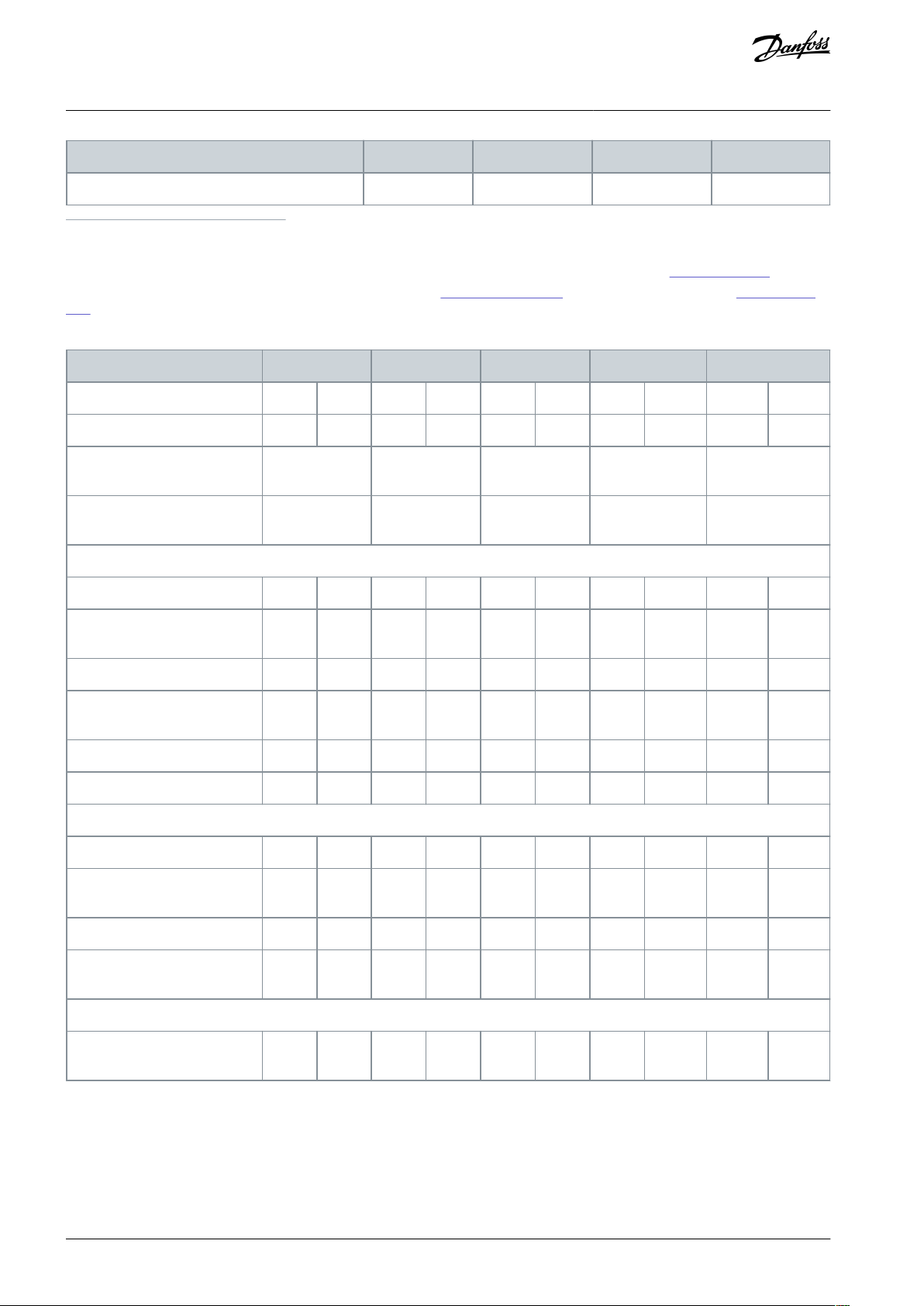
Type designation
P11K
P15K
P18K
P22K
Efficiency
(3)
0.98
0.98
0.98
0.98
Type designation
P30K
P37K
P45K
P55K
P75K
High/normal overload
(1)
HONOHONOHONOHONOHONOTypical shaft output [kW/(hp)]
30 (40)
37 (50)
37 (50)
45 (60)
45 (60)
55 (75)
55 (75)
75 (100)
75 (100)
90 (125)
Enclosure protection rating
IP20
B4C3C3C4C4
Enclosure protection rating
IP21, IP55, IP66
C1C1C1C2C2
Output current
Continuous (380–440 V) [A]
6173739090
106
106
147
147
177
Intermittent (60 s overload)
(380–440 V) [A]
91.5
80.3
11099135
117
159
162
221
195
Continuous (441–500 V) [A]
5265658080
105
105
130
130
160
Intermittent (60 s overload)
(441–500 V) [A]
78
71.5
97.588120
116
158
143
195
176
Continuous kVA (400 V) [kVA]
42.3
50.6
50.6
62.4
62.4
73.4
73.4
102
102
123
Continuous kVA (460 V) [kVA]
–
51.8–63.7–83.7–104–128
Maximum input current
Continuous (380–440 V) [A]
55666682829696
133
133
161
Intermittent (60 s overload)
(380–440 V) [A]
82.5
72.69990.2
123
106
144
146
200
177
Continuous (441–500 V) [A]
47595973739595
118
118
145
Intermittent (60 s overload)
(441–500 V) [A]
70.5
64.9
88.5
80.3
110
105
143
130
177
160
Additional specifications
Estimated power loss at rated
maximum load [W]
(2)
570
698
697
843
891
1083
1022
1384
1232
1474
VLT® AutomationDrive FC 301/FC 302
Operating Guide
1
High overload=150% or 160% torque for a duration of 60 s. Normal overload=110% torque for a duration of 60 s.
2
Applies for dimensioning of drive cooling. If the switching frequency is higher than the default setting, the power losses may increase. LCP and
typical control card power consumptions are included. For power loss data according to EN 50598-2, refer to Danfoss
3
Efficiency measured at nominal current. For energy efficiency class, see
mart website.
Table 34: Mains Supply 380–500 V (FC 302), 380–480 V (FC 301), P30K–P75K
8.4 Ambient Conditions. For part load losses, see Danfoss MyDrive® ecoS-
MyDrive® ecoSmart website.
Specifications
AQ267037727118en-000101 / 130R030064 | Danfoss A/S © 2021.01

Type designation
P30K
P37K
P45K
P55K
P75K
Efficiency
(3)
0.98
0.98
0.98
0.98
0.99
Type designation
PK75
P1K1
P1K5
P2K2
P3K0
P4K0
P5K5
P7K5
Typical shaft output [kW/(hp)]
0.75 (1)
1.1 (1.5)
1.5 (2.0)
2.2 (3.0)
3 (4.0)
4 (5.0)
5.5 (7.5)
7.5 (10)
Enclosure protection rating IP20, IP21
A3A3A3A3A3A3A3A3Enclosure protection rating IP55
A5A5A5A5A5A5A5
A5
Output current
Continuous (525–550 V) [A]
1.8
2.6
2.9
4.1
5.2
6.4
9.5
11.5
Intermittent (525–550 V) [A]
2.9
4.2
4.6
6.6
8.3
10.2
15.2
18.4
Continuous (551–600 V) [A]
1.7
2.4
2.7
3.9
4.9
6.1
9.011Intermittent (551–600 V) [A]
2.7
3.8
4.3
6.2
7.8
9.8
14.4
17.6
Continuous kVA (525 V) [kVA]
1.7
2.5
2.8
3.9
5.0
6.1
9.011Continuous kVA (57 V) [kVA]
1.7
2.4
2.7
3.9
4.9
6.1
9.0
11
Maximum input current
Continuous (525–600 V) [A]
1.7
2.4
2.7
4.1
5.2
5.8
8.6
10.4
Intermittent (525–600 V) [A]
2.7
3.8
4.3
6.6
8.3
9.3
13.8
16.6
Additional specifications
Estimated power loss at rated maximum load [W]
(1)
35506592122
145
195
261
Efficiency
(2)
0.97
0.97
0.97
0.97
0.97
0.97
0.97
0.97
Type designation
P11K
P15K
P18K
P22K
P30K
High/normal load
(1)
HONOHONOHONOHONOHINOTypical shaft output [kW/(hp)]
11 (15)
15 (20)
15 (20)
18.5 (25)
18.5 (25)
22 (30)
22 (30)
30 (40)
30 (40)
37 (50)
Enclosure protection rating
IP20
B3B3B4B4B4
VLT® AutomationDrive FC 301/FC 302
Operating Guide
1
High overload=150% or 160% torque for a duration of 60 s. Normal overload=110% torque for a duration of 60 s.
2
Applies for dimensioning of drive cooling. If the switching frequency is higher than the default setting, the power losses may increase. LCP and
typical control card power consumptions are included. For power loss data according to EN 50598-2, refer to Danfoss
3
Efficiency measured at nominal current. For energy efficiency class, see
mart website.
8.4 Ambient Conditions. For part load losses, see Danfoss MyDrive® ecoS-
MyDrive® ecoSmart website.
Specifications
8.1.3 Mains Supply 525–600 V (FC 302 only)
Table 35: Mains Supply 525–600 V (FC 302 only), PK75–P7K5
1
Applies for dimensioning of drive cooling. If the switching frequency is higher than the default setting, the power losses may increase. LCP and
typical control card power consumptions are included. For power loss data according to EN 50598-2, refer to Danfoss
2
Efficiency measured at nominal current. For energy efficiency class, see 8.4 Ambient Conditions. For part load losses, see Danfoss MyDrive® ecoS-
mart website.
Table 36: Mains Supply 525–600 V (FC 302 only), P11K–P30K
MyDrive® ecoSmart website.
AQ267037727118en-000101 / 130R0300 | 65Danfoss A/S © 2021.01

Type designation
P11K
P15K
P18K
P22K
P30K
Enclosure protection rating
IP21, IP55, IP66
B1B1B2B2C1
Output current
Continuous (525–550 V) [A]
19232328283636434354Intermittent (525–550 V) [A]
30253731454058476559Continuous (551–600 V) [A]
18222227273434414152Intermittent (551–600 V) [A]
29243530433754456257Continuous kVA (550 V) [kVA]
18.1
21.9
21.9
26.7
26.7
34.3
34.34141
51.4
Continuous kVA (575 V) [kVA]
17.9
21.9
21.9
26.9
26.9
33.9
33.9
40.8
40.8
51.8
Maximum input current
Continuous at 550 V [A]
17.2
20.9
20.9
25.4
25.4
32.7
32.7393949Intermittent at 550 V [A]
28233328413652435954Continuous at 575 V [A]
16202024243131373747Intermittent at 575 V [A]
262232273934504156
52
Additional specifications
Estimated power loss at rated
maximum load [W]
(2)
220
300
300
370
370
440
440
600
600
740
Efficiency
(3)
0.98
0.98
0.98
0.98
0.98
Type designation
P37K
P45K
P55K
P75K
High/normal load
(1)
HONOHONOHONOHONOTypical shaft output [kW/(hp)]
37 (50)
45 (60)
45 (60)
55 (75)
55 (75)
75 (100)
75 (100)
90 (125)
Enclosure protection rating IP20
C3C3C3C4C4
Enclosure protection rating IP21, IP55, IP66
C1C1C1C2C2
Output current
Continuous (525–550 V) [A]
5465658787
105
105
137
Intermittent (525–550 V) [A]
81729896131
116
158
151
Continuous (551–600 V) [A]
5262628383
100
100
131
Intermittent (551–600 V) [A]
78689391125
110
150
144
Continuous kVA (550 V) [kVA]
51.4
61.9
61.9
82.9
82.9
100
100
130.5
VLT® AutomationDrive FC 301/FC 302
Operating Guide
Specifications
1
High overload=150% or 160% torque for a duration of 60 s. Normal overload=110% torque for a duration of 60 s.
2
Applies for dimensioning of drive cooling. If the switching frequency is higher than the default setting, the power losses may increase. LCP and
typical control card power consumptions are included. For power loss data according to EN 50598-2, refer to Danfoss
3
Efficiency measured at nominal current. For energy efficiency class, see 8.4 Ambient Conditions. For part load losses, see Danfoss MyDrive® ecoS-
mart website.
Table 37: Mains Supply 525–600 V P37K–P75K (FC 302 only), P37K–P75K
MyDrive® ecoSmart website.
AQ267037727118en-000101 / 130R030066 | Danfoss A/S © 2021.01

Type designation
P37K
P45K
P55K
P75K
Continuous kVA (575 V) [kVA]
51.8
61.7
61.7
82.7
82.7
99.6
99.6
130.5
Maximum input current
Continuous at 550 V [A]
495959
78.9
78.9
95.3
95.3
124.3
Intermittent at 550 V [A]
74658987118
105
143
137
Continuous at 575 V [A]
47565675759191
119
Intermittent at 575 V [A]
70628583113
100
137
131
Additional specifications
Estimated power loss at rated maximum load [W]
(2)
740
900
900
1100
1100
1500
1500
1800
Efficiency
(3)
0.98
0.98
0.98
0.98
Type designation
P1K1
P1K5
P2K2
P3K0
P4K0
P5K5
P7K5
High/normal overload
(1)
HO/NO
HO/NO
HO/NO
HO/NO
HO/NO
HO/NO
HO/NO
Typical shaft output [kW/(hp)]
1.1 (1.5)
1.5 (2.0)
2.2 (3.0)
3.0 (4.0)
4.0 (5.0)
5.5 (7.5)
7.5 (10)
Enclosure protection rating IP20
A3A3A3A3A3A3A3
Output current
Continuous (525–550 V) [A]
2.1
2.7
3.9
4.9
6.1
9.011Intermittent (525–550 V) [A]
3.4
4.3
6.2
7.8
9.8
14.4
17.6
Continuous (551–690 V) [A]
1.6
2.2
3.2
4.5
5.5
7.510Intermittent (551–690 V) [A]
2.6
3.5
5.1
7.2
8.81216
Continuous kVA 525 V
1.9
2.5
3.5
4.5
5.5
8.210Continuous kVA 690 V
1.9
2.6
3.8
5.4
6.6
9.0
12
Maximum input current
Continuous (525–550 V) [A]
1.9
2.4
3.5
4.4
5.5
8.1
9.9
Intermittent (525–550 V) [A]
3.0
3.9
5.6
7.0
8.8
12.9
15.8
Continuous (551–690 V) [A]
1.4
2.0
2.9
4.0
4.9
6.7
9.0
Intermittent (551–690 V) [A]
2.3
3.2
4.6
6.5
7.9
10.8
14.4
Additional specifications
VLT® AutomationDrive FC 301/FC 302
Operating Guide
1
High overload=150% or 160% torque for a duration of 60 s. Normal overload=110% torque for a duration of 60 s.
2
Applies for dimensioning of drive cooling. If the switching frequency is higher than the default setting, the power losses may increase. LCP and
typical control card power consumptions are included. For power loss data according to EN 50598-2, refer to Danfoss
3
Efficiency measured at nominal current. For energy efficiency class, see 8.4 Ambient Conditions. For part load losses, see Danfoss MyDrive® ecoS-
mart website.
MyDrive® ecoSmart website.
Specifications
8.1.4 Mains Supply 525–690 V (FC 302 only)
Table 38: A3 Enclosure, Mains Supply 525–690 V IP20/Protected Chassis, P1K1–P7K5
AQ267037727118en-000101 / 130R0300 | 67Danfoss A/S © 2021.01
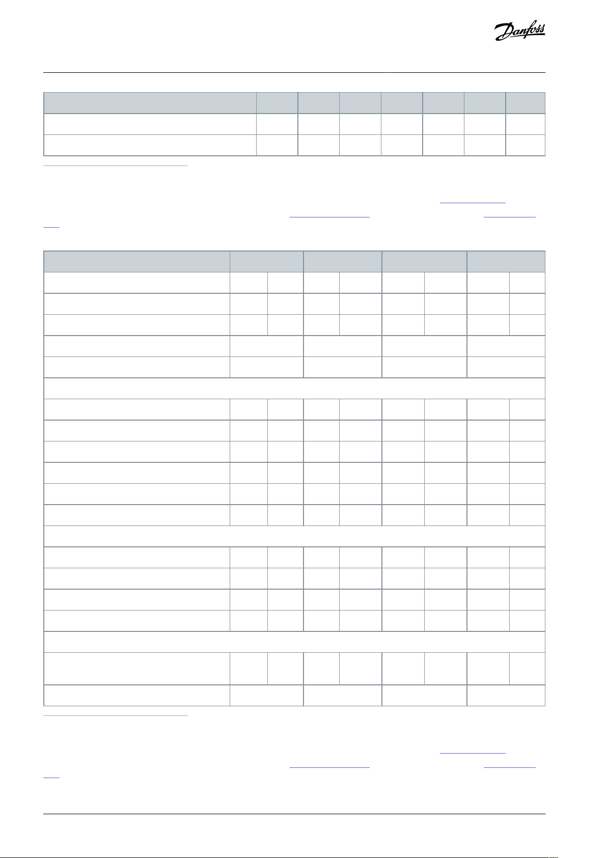
Type designation
P1K1
P1K5
P2K2
P3K0
P4K0
P5K5
P7K5
Estimated power loss at rated maximum load [W]
(2)
446088
120
160
220
300
Efficiency
(3)
0.96
0.96
0.96
0.96
0.96
0.96
0.96
Type designation
P11K
P15K
P18K
P22K
High/normal overload
(1)
HONOHONOHONOHONOTypical shaft output at 550 V [kW/(hp)]
7.5 (10)
11 (15)
11 (15)
15 (20)
15 (20)
18.5 (25)
18.5 (25)
22 (30)
Typical shaft output at 690 V [kW/(hp)]
11 (15)
15 (20)
15 (20)
18.5 (25)
18.5 (25)
22 (30)
22 (30)
30 (40)
Enclosure protection rating IP20
B4B4B4B4Enclosure protection rating IP21, IP55
B2B2B2
B2
Output current
Continuous (525–550 V) [A]
1419192323282836Intermittent (60 s overload) (525–550 V) [A]
22.4
20.9
30.4
25.3
36.8
30.8
44.8
39.6
Continuous (551–690 V) [A]
1318182222272734Intermittent (60 s overload) (551–690 V) [A]
20.8
19.8
28.8
24.2
35.2
29.7
43.2
37.4
Continuous kVA (at 550 V) [kVA]
13.3
18.1
18.1
21.9
21.9
26.7
26.7
34.3
Continuous kVA (at 690 V) [kVA]
15.5
21.5
21.5
26.3
26.3
32.3
32.3
40.6
Maximum input current
Continuous (at 550 V) (A)
15
19.5
19.52424292936Intermittent (60 s overload) (at 550 V) (A)
23.2
21.5
31.2
26.4
38.4
31.9
46.4
39.6
Continuous (at 690 V) (A)
14.5
19.5
19.52424292936Intermittent (60 s overload) (at 690 V) (A)
23.2
21.5
31.2
26.4
38.4
31.9
46.4
39.6
Additional specifications
Estimated power loss at rated maximum load
[W]
(2)
150
220
220
300
300
370
370
440
Efficiency
(3)
0.98
0.98
0.98
0.98
VLT® AutomationDrive FC 301/FC 302
Operating Guide
1
High overload=150% or 160% torque for a duration of 60 s. Normal overload=110% torque for a duration of 60 s.
2
Applies for dimensioning of drive cooling. If the switching frequency is higher than the default setting, the power losses may increase. LCP and
typical control card power consumptions are included. For power loss data according to EN 50598-2, refer to Danfoss
3
Efficiency measured at nominal current. For energy efficiency class, see
mart website.
Table 39: B2/B4 Enclosure, Mains Supply 525–690 V IP20/IP21/IP55 - Chassis/NEMA 1/NEMA 12 (FC 302 only), P11K–P22K
8.4 Ambient Conditions. For part load losses, see Danfoss MyDrive® ecoS-
MyDrive® ecoSmart website.
Specifications
1
High overload=150% or 160% torque for a duration of 60 s. Normal overload=110% torque for a duration of 60 s.
2
Applies for dimensioning of drive cooling. If the switching frequency is higher than the default setting, the power losses may increase. LCP and
typical control card power consumptions are included. For power loss data according to EN 50598-2, refer to Danfoss
3
Efficiency measured at nominal current. For energy efficiency class, see
mart website.
MyDrive® ecoSmart website.
8.4 Ambient Conditions. For part load losses, see Danfoss MyDrive® ecoS-
AQ267037727118en-000101 / 130R030068 | Danfoss A/S © 2021.01

Type designation
P30K
P37K
P45K
P55K
P75K
High/normal overload
(1)
HONOHONOHONOHONOHO
NO
Typical shaft output at 550 V
[kW/(hp)]
22 (30)
30 (40)
30 (40)
37 (50)
37 (50)
45 (60)
45 (60)
55 (75)
55 (75)
75 (100)
Typical shaft output at 690 V
[kW/(hp)]
30 (40)
37 (50)
37 (50)
45 (60)
45 (60)
55 (75)
55 (75)
75 (100)
75 (100)
90 (125)
Enclosure protection rating
IP20
B4C3C3
D3h
D3h
Enclosure protection rating
IP21, IP55
C2C2C2C2C2
Output current
Continuous (525–550 V) [A]
364343545465658787
105
Intermittent (60 s overload)
(525–550 V) [A]
54
47.3
64.5
59.48171.5
97.5
95.7
130.5
115.5
Continuous (551–690 V) [A]
344141525262628383
100
Intermittent (60 s overload)
(551–690 V) [A]
51
445.1
61.5
57.27868.29391.3
124.5
110
Continuous kVA (at 550 V)
[kVA]
34.34141
51.4
51.4
61.9
61.9
82.9
82.9
100
Continuous kVA (at 690 V)
[kVA]
40.64949
62.1
62.1
74.1
74.1
99.2
99.2
119.5
Maximum input current
Continuous (at 550 V) [A]
364949595971718787
99
Intermittent (60 s overload) (at
550 V) [A]
54
53.97264.98778.1
105
95.7
129
108.9
Continuous (at 690 V) [A]
3648485858707086–
–
Intermittent (60 s overload) (at
690 V) [A]
54
52.87263.88777
105
94.6––
Additional specifications
Estimated power loss at rated
maximum load [W]
(2)
600
740
740
900
900
1100
1100
1500
1500
1800
Efficiency
(3)
0.98
0.98
0.98
0.98
0.98
VLT® AutomationDrive FC 301/FC 302
Operating Guide
Table 40: B4, C2, C3 Enclosure, Mains Supply 525–690 V IP20/IP21/IP55 – Chassis/NEMA1/NEMA 12 (FC 302 only), P30K–P75K
Specifications
1
High overload=150% or 160% torque for a duration of 60 s. Normal overload=110% torque for a duration of 60 s.
2
Applies for dimensioning of drive cooling. If the switching frequency is higher than the default setting, the power losses may increase. LCP and
typical control card power consumptions are included. For power loss data according to EN 50598-2, refer to Danfoss
3
Efficiency measured at nominal current. For energy efficiency class, see 8.4 Ambient Conditions. For part load losses, see Danfoss MyDrive® ecoS-
mart website.
MyDrive® ecoSmart website.
AQ267037727118en-000101 / 130R0300 | 69Danfoss A/S © 2021.01

Enclosure
Mains
Motor
Brake
Loadshare
Disconnect
A1
4(12)
4(12)
4(12)
4(12)
4(12)A24(12)
4(12)
4(12)
4(12)
4(12)A34(12)
4(12)
4(12)
4(12)
4(12)A44(12)
4(12)
4(12)
4(12)
4(12)A54(12)
4(12)
4(12)
4(12)
4(12)B110(7)
10(7)
10(7)
10(7)
10(7)B235(2)
35(2)
35(2)
35(2)
35(2)B310(7)
10(7)
10(7)
10(7)
10(7)B435(2)
35(2)
35(2)
35(2)
35(2)C150(1/0)
50(1/0)
50(1/0)
50(1/0)
50(1/0)
C2
95(4/0)
95(4/0)
95(4/0)
95(4/0)
95(4/0)
C3
50(1/0)
50(1/0)
50(1/0)
50(1/0)
50(1/0)
C4
95(4/0)
95(4/0)
95(4/0)
95(4/0)
95(4/0)
Supply terminals (6-pulse)
L1, L2, L3
Supply terminals (12-pulse)
L1-1, L2-1, L3-1, L1-2, L2-2, L3-2
Supply voltage
(1)(2)
200–240 V ±10%
Supply voltage
(1)(2)
FC 301: 380–480 V/FC 302: 380–500 V ±10%
Supply voltage
(1)(2)
FC 302: 525–600 V ±10%
Supply voltage
(1)(2)
FC 302: 525–690 V ±10%
Supply frequency
47.5–63 Hz
Maximum imbalance temporary between mains phases
3.0% of rated supply voltage
True power factor (λ)
≥0.9 nominal at rated load
Displacement power factor (cos Φ)
Near unity (>0.98)
Switching on the input supply L1, L2, L3 (power-ups) ≤7.5 kW
(10 hp)
Maximum twice per minute
Switching on input supply L1, L2, L3 (power-ups) 11–75 kW (15–
101 hp)
Maximum once per minute
Switching on input supply L1, L2, L3 (power-ups) ≥90 kW (121 hp)
Maximum once per 2 minutes
Environment according to EN60664-1
Overvoltage category III/pollution degree 2
VLT® AutomationDrive FC 301/FC 302
Operating Guide
8.1.5 Power Cable Cross-sections
Table 41: Maximum Cable Cross-section [mm2 (AWG)]
Specifications
8.2 Mains Supply
1
Mains voltage low/mains dropout: During low mains voltage or a mains dropout, the drive continues until the DC-link voltage drops below the
minimum stop level, which typically corresponds to 15% below the drive's lowest rated supply voltage. Power-up and full torque cannot be exptected at mains voltage lower than 10% below the drive's lowest rated supply voltage.
2
The unit is suitable for use on a circuit capable of delivering not more than 100000 RMS symmetrical Amperes, 240/500/600/690 V maximum.
AQ267037727118en-000101 / 130R030070 | Danfoss A/S © 2021.01

Output voltage
0–100% of supply voltage
Output frequency
0–590 Hz
(1)
Output frequency in flux mode
0–300 Hz
Switching on output
Unlimited
Ramp times
0.01–3600 s
Starting torque (constant torque)
Maximum 160% for 60 s
(1)
once in 10 minutes
Starting/overload torque (variable torque)
Maximum 110% up to 0.5 s
(1)
once in 10 minutes
Torque rise time in flux (for 5 KHz fsw)
1 ms
Torque rise time in VVC+ (independent of fsw)
10 ms
Enclosure
IP20 (Chassis), IP21 (Type 1), IP54 (Type 12)
Vibration test (standard/ruggedized)
0.7 g/1.0 g
Relative humidty
5%-95% (IEC 721-3-3; Class 3K3 (non-condensing) during opera-
tion)
Aggressive environment (IEC 60068-2-43) H2S test
Class Kd
Aggressive gases (IEC 60721-3-3)
Class 3C3
Test method according to IEC 60068-2-43
H2S (10 days)
Ambient temperature (at SFAVM switching mode)
- with derating
Maximum 55° C (131° F)
(1)
- with full output power of typical EFF2 motors (up to 90% output
current)
Maximum 50° C (122° F)
(1)
- at full continuous FC output current
Maximum 45° C (113° F)
(1)
Minimum ambient temperature during full-scale operation
0 °C (32 °F)
Minimum ambient temperature at reduced speed performance
-10 °C (14 °F)
Temperature during storage/transport
-25 to +65/70 °C (-13 to +149/158 °F)
Maximum altitude above sea level without derating
1000 m (3280 ft)
Maximum altitude above sea level with derating
3000 m (9842 ft)
EMC standards, Emission
IEC/EN 61800-3
EMC standards, Immunity
IEC/EN 61800-3
Energy efficiency class
IE2
(2)
VLT® AutomationDrive FC 301/FC 302
Operating Guide
8.3 Motor Output and Motor Data
8.3.1 Motor Output (U, V, W)
1
Dependent on voltage and power.
8.3.2 Torque Characteristics
1
Percentage relates to the nominal torque
Specifications
8.4 Ambient Conditions
1
For more information, see the Derating section in the Design Guide.
2
Determined according to IEC 61800-9-2 (EN 50598-2) at:
Rated load.
•
90% rated frequency.
•
Switching frequency factory setting.
•
Switching pattern factory setting.
•
AQ267037727118en-000101 / 130R0300 | 71Danfoss A/S © 2021.01

Maximum motor cable length, shielded
FC 301: 50 m (164 ft)/FC 302: 150 m (492 ft)
Maximum motor cable length, unshielded
FC 301: 75 m (246 ft)/FC 302: 300 m (984 ft)
Maximum cross-section to control terminals, flexible/rigid wire
without cable end sleeves
1.5 mm2/16 AWG
Maximum cross-section to control terminals, flexible wire with cable end sleeves
1 mm2/18 AWG
Maximum cross-section to control terminals, flexible wire with cable end sleeves with collar
0.5 mm2/20 AWG
Minimum cross-section to control terminals
0.25 mm2/24 AWG
Programmable digital inputs
FC 301: 4 (5)
(1)
/FC 302: 4 (6)
(1)
Terminal number
18, 19, 27
(1)
, 29
(1)
, 32, 33
Logic
PNP or NPN
Voltage level
0–24 V DC
Voltage level, logic 0 PNP
<5 V DC
Voltage level, logic 1, PNP
>10 V DC
Voltage level, logic 0 NPN
(2)
>19 V DC
Voltage level, logic 1 NPN
(2)
<14 V DC
Maximum voltage on input
28 V DC
Pulse frequency range
0–110 kHz
(Duty cycle) minimum pulse width
4.5 ms
Input resistance, R
i
Approximately 4 kΩ
Voltage level
0–24 V DC
Voltage level, logic 0 PNP
<4 V DC
Voltage level, logic 1 PNP
>20 V DC
Maximum voltage on input
28 V DC
Typical input current at 24 V
50 mA rms
Typical input current at 20 V
60 mA rms
Input capacitance
400 nF
VLT® AutomationDrive FC 301/FC 302
Operating Guide
8.5 Cable Specifications
8.5.1 Cable Lengths and Cross-sections for Control Cables
For power cables, see Table 29 to Table 40
For power cables cross-sections, see 8.1.5 Power Cable Cross-sections.
8.6 Control Input/Output and Control Data
8.6.1 Digital Inputs
Specifications
1
Terminals 27 and 29 can also be programmed as output.
2
Except STO input terminal 37.
8.6.2 STO Terminal 37 (Terminal 37 is Fixed PNP Logic)
All digital inputs are galvanically isolated from the supply voltage (PELV) and other high-voltage terminals.
See 4.7.1 Safe Torque Off (STO) for further information about terminal 37 and Safe Torque Off.
When using a contactor with a DC coil inside in combination with STO, it is important to make a return way for the current from the
coil when turning it off. This can be done by using a freewheel diode (or, alternatively, a 30 V or 50 V MOV for quicker response time)
across the coil. Typical contactors can be bought with this diode.
AQ267037727118en-000101 / 130R030072 | Danfoss A/S © 2021.01

Number of analog inputs
2
Terminal number
53, 54
Modes
Voltage or current
Mode select
Switch S201 and switch S202
Voltage mode
Switch S201/switch S202 = OFF (U)
Voltage level
-10 V to +10 V (scaleable)
Input resistance, R
i
Approximately 10 kΩ
Maximum voltage
±20 V
Current mode
Switch S201/S202 = ON (I)
Current level
0/4 to 20 mA (scaleable)
Input resistance, R
i
Approximately 200 Ω
Maximum current
30 mA
Resolution for analog inputs
10 bit (+ sign)
Accuracy of analog inputs
Maximum error 0.5% of full scale
Bandwidth
100 Hz
Mains
Functional
isolation
PELV isolation
Motor
DC-bus
High
voltage
Control
+24 V
RS485
18
37
e30ba117.11
Programmable pulse/encoder inputs
2/1
Terminal number pulse/encoder
29
(1)
, 33
(2)
/32
(3)
, 33
(3)
Maximum frequency at terminals 29, 32, 33
110 kHz (Push-pull driven)
Maximum frequency at terminals 29, 32, 33
5 kHz (Open collector)
Maximum frequency at terminals 29, 32, 33
4 Hz
Voltage level
See 8.6.1 Digital Inputs.
Maximum voltage on input
28 V DC
Input resistance, R
i
Approximately 4 kΩ
Pulse input accuracy (0.1–1 kHz)
Maximum error: 0.1% of full scale
Encoder input accuracy (1–11 kHz)
Maximum error: 0.05% of full scale
VLT® AutomationDrive FC 301/FC 302
Operating Guide
8.6.3 Analog Inputs
The analog inputs are galvanically isolated from the supply voltage (PELV) and other high-voltage terminals.
Specifications
Illustration 20: PELV Isolation
8.6.4 Pulse/Encoder Inputs
1
FC 302 only.
2
Pulse inputs are 29 and 33.
3
Encoder inputs: 32=A, 33=B.
The pulse and encoder inputs (terminals 29, 32, 33) are galvanically isolated from the supply voltage (PELV) and other high-voltage
terminals.
AQ267037727118en-000101 / 130R0300 | 73Danfoss A/S © 2021.01

Programmable digital/pulse outputs
2
Terminal number
27, 29
(1)
Voltage level at digital/frequency output
0–24 V
Maximum output current (sink or source)
40 mA
Maximum load at frequency output
1 kΩ
Maximum capacitive load at frequency output
10 nF
Minimum output frequency at frequency output
0 Hz
Maximum output frequency at frequency output
32 kHz
Accuracy of frequency output
Maximum error: 0.1% of full scale
Resolution of frequency outputs
12 bit
Number of programmable outputs
1
Terminal number
42
Current range at analog output
0/4 to 20 mA
Maximum load GND - analog output less than
500 Ω
Accuracy on analog output
Maximum error: 0.5% of full scale
Resolution of analog output
12 bit
Terminal number
12, 13
Output voltage
24 V +1, -3 V
Maximum load
200 mA
Terminal number
50
Output voltage
10.5 V ±0.5 V
Maximum load
15 mA
Terminal number
68 (P,TX+, RX+), 69 (N,TX-, RX-)
Terminal number 61
Common for terminals 68 and 69
USB standard
1.1 (full speed)
USB plug
USB type B plug
VLT® AutomationDrive FC 301/FC 302
Operating Guide
8.6.5 Digital Outputs
1
Terminals 27 and 29 can also be programmed as input.
The digital output is galvanically isolated from the supply voltage (PELV) and other high-voltage terminals.
8.6.6 Analog Output
Specifications
The analog output is galvanically isolated from the supply voltage (PELV) and other high-voltage terminals.
8.6.7 Control Card, 24 V DC Output
The 24 V DC supply is galvanically isolated from the supply voltage (PELV), but has the same potential as the analog and digital
inputs and outputs.
8.6.8 Control Card, +10 V DC Output
The 10 V DC supply is galvanically isolated from the supply voltage (PELV) and other high-voltage terminals.
8.6.9 Control Card, RS485 Serial Communication
The RS485 serial communication circuit is galvanically isolated from the supply voltage (PELV).
8.6.10 Control Card, USB Serial Communication
Connection to the PC is carried out via a standard host/device USB cable.
AQ267037727118en-000101 / 130R030074 | Danfoss A/S © 2021.01

Programmable relay outputs
FC 301 all kW: 1/FC 302 all kW: 2
Relay 01 terminal number
1–3 (break), 1–2 (make)
Maximum terminal load (AC-1)
(1)
on 1–3 (NC), 1–2 (NO) (resistive
load)
240 V AC, 2 A
Maximum terminal load (AC-15)
(1)
(inductive load @ cosφ 0.4)
240 V AC, 0.2 A
Maximum terminal load (DC-1)
(1)
on 1–2 (NO), 1–3 (NC) (resistive
load)
60 V DC, 1 A
Maximum terminal load (DC-13)
(1)
(inductive load)
24 V DC, 0.1 A
Relay 02 (FC 302 only) terminal number
4–6 (break), 4–5 (make)
Maximum terminal load (AC-1)
(1)
on 4–5 (NO) (resistive load)
(2)(3)
400 V AC, 2 A
Maximum terminal load (AC-15)
(1)
on 4–5 (NO) (inductive load @
cosφ 0.4)
240 V AC, 0.2 A
Maximum terminal load (DC-1)
(1)
on 4–5 (NO) (resistive load)
80 V DC, 2 A
Maximum terminal load (DC-13)
(1)
on 4–5 (NO) (inductive load)
24 V DC, 0.1 A
Maximum terminal load (AC-1)
(1)
on 4–6 (NC) (resistive load)
240 V AC, 2 A
Maximum terminal load (AC-15)
(1)
on 4–6 (NC) (inductive load @
cosφ 0.4)
240 V AC, 0.2 A
Maximum terminal load (DC-1)
(1)
on 4–6 (NC) (resistive load)
50 V DC, 2 A
Maximum terminal load (DC-13)
(1)
on 4–6 (NC) (inductive load)
24 V DC, 0.1 A
Minimum terminal load on 1–3 (NC), 1–2 (NO), 4–6 (NC), 4–5 (NO)
24 V DC 10 mA, 24 V AC 20 mA
Environment according to EN 60664-1
Overvoltage category III/pollution degree 2
Scan interval
1 ms
Resolution of output frequency at 0–590 Hz
±0.003 Hz
Repeat accuracy of precise start/stop (terminals 18, 19)
≤±0.1 ms
System response time (terminals 18, 19, 27, 29, 32, 33)
≤2 ms
Speed control range (open loop)
1:100 of synchronous speed
Speed control range (closed loop)
1:1000 of synchronous speed
Speed accuracy (open loop)
30–4000 RPM: Error ±8 RPM
Speed accuracy (closed loop), depending on resolution of feedback device
0–6000 RPM: Error ±0.15 RPM
Torque control accuracy (speed feedback)
Maximum error ±5% of rated torque
VLT® AutomationDrive FC 301/FC 302
Operating Guide
Specifications
The USB connection is galvanically isolated from the supply voltage (PELV) and other high-voltage terminals.
The USB ground connection is not galvanically isolated from protective earth. Use only an isolated laptop as PC connection to the
USB connector on the drive.
8.6.11 Relay Outputs
1
IEC 60947 parts 4 and 5. The relay contacts are galvanically isolated from the rest of the circuit by reinforced isolation (PELV)
2
Overvoltage Category II
3
UL applications 300 V AC 2 A.
8.6.12 Control Card Performance
8.6.13 Control Characteristics
All control characteristics are based on a 4-pole asynchronous motor.
AQ267037727118en-000101 / 130R0300 | 75Danfoss A/S © 2021.01

Enclosure
Power [kW (hp)]
Recommended
fuse size
Recommended
maximum fuse
Recommended circuit
breaker Moeller
Maximum trip
level [A]
A1
0.25–1.5 (0.34–2.0)
gG-10
gG-25
PKZM0-16
16A20.25–1.5 (0.34–2.0)
gG-10
gG-25
PKZM0-25
25
2.2 (3.0)
gG-16
A3
3.0 (4.0)
gG-16
gG-32
PKZM0-25
25
3.7 (5.0)
gG-20
A4
0.25–1.5 (0.34–2.0)
gG-10
gG-32
PKZM0-25
25
2.2 (3.0)
gG-16
A5
0.25–1.5 (0.34–2.0)
gG-10
gG-32
PKZM0-25
25
2.2–3.0 (3.0–4.0)
gG-16
3.7 (5.0)
gG-20
B1
5.5 (7.5)
gG-25
gG-80
PKZM4-63
63
7.5 (10.0)
gG-32
B2
11.0 (15.0)
gG-50
gG-100
NZMB1-A100
100B35.5 (7.5)
gG-25
gG-63
PKZM4-50
50B47.5 (10.0)
gG-32
gG-125
NZMB1-A100
100
11.0 (15.0)
gG-50
15.0 (20.0)
gG-63
C1
15.0 (20.0)
gG-63
gG-160
NZMB2-A200
160
18.5 (25.0)
gG-80
VLT® AutomationDrive FC 301/FC 302
Operating Guide
Specifications
8.7 Fuses and Circuit Breakers
8.7.1 Fuse Recommendations
Fuses ensure that possible damage to the drive is limited to damage inside the unit. Danfoss recommends fuses and/or circuit
breakers on the supply side as protection. For further information, see Application Note Fuses and Circuit Breakers.
N O T I C E
Use of fuses on the supply side is mandatory for IEC 60364 (CE) and NEC 2009 (UL) compliant installations.
Recommendations
•
gG type fuses.
•
Moeller type circuit breakers. For other circuit breaker types, ensure that the energy into the drive is equal to or lower than the
energy provided by Moeller types.
For further information, see Application Note Fuses and Circuit Breakers.
The recommended fuses in 8.7.2 CE Compliance and 8.7.3 UL Compliance are suitable for use on a circuit capable of 100000 A
(symmetrical), depending on the drive voltage rating. With the proper fusing, the drive short circuit current rating (SCCR) is
10000 A
8.7.2 CE Compliance
Table 42: 200–240 V, Enclosure Sizes A, B, and C
rms
.
rms
AQ267037727118en-000101 / 130R030076 | Danfoss A/S © 2021.01

Enclosure
Power [kW (hp)]
Recommended
fuse size
Recommended
maximum fuse
Recommended circuit
breaker Moeller
Maximum trip
level [A]
22.0 (30.0)
gG-100
aR-160
C2
30.0 (40.0)
aR-160
aR-200
NZMB2-A250
250
37.0 (50.0)
aR-200
aR-250
C3
18.5 (25.0)
gG-80
gG-150
NZMB2-A200
150
22.0 (30.0)
aR-125
aR-160
C4
30.0 (40.0)
aR-160
aR-200
NZMB2-A250
250
37.0 (50.0)
aR-200
aR-250
Enclosure
Power [kW (hp)]
Recommended
fuse size
Recommended
maximum fuse
Recommended circuit breaker Moeller
Maximum trip
level [A]
A1
0.37–1.5 (0.5–2.0)
gG-10
gG-25
PKZM0-16
16A20.37–3.0 (0.5–4.0)
gG-10
gG-25
PKZM0-25
25
4.0 (5.0)
gG-16
A3
5.5–7.5 (7.5–10.0)
gG-16
gG-32
PKZM0-25
25A40.37-3.0 (0.5–4.0)
gG-10
gG-32
PKZM0-25
25
4.0 (5.0)
gG-16
A5
0.37–3.0 (0.5–4.0)
gG-10
gG-32
PKZM0-25
25
4.0–7.5 (5.0–10.0)
gG-16
B1
11–15 (15.0–20.0)
gG-40
gG-80
PKZM4-63
63B218.5 (25.0)
gG-50
gG-100
NZMB1-A100
100
22.0 (30.0)
gG-63
B3
11–15 (15.0–20.0)
gG-40
gG-63
PKZM4-50
50B418.5 (25.0)
gG-50
gG-125
NZMB1-A100
100
22.0 (30.0)
gG-63
30.0 (40.0)
gG-80
C1
30.0 (40.0)
gG-80
gG-160
NZMB2-A200
160
37.0 (50.0)
gG-100
45.0 (60.0)
gG-160
C2
55.0 (75.0)
aR-200
aR-250
NZMB2-A250
250
75.0 (100.0)
aR-250
C3
37.0 (50.0)
gG-100
gG-150
NZMB2-A200
150
45.0 (60.0)
gG-160
gG-160
VLT® AutomationDrive FC 301/FC 302
Operating Guide
Table 43: 380–500 V, Enclosure Sizes A, B, and C
Specifications
AQ267037727118en-000101 / 130R0300 | 77Danfoss A/S © 2021.01

Enclosure
Power [kW (hp)]
Recommended
fuse size
Recommended
maximum fuse
Recommended circuit breaker Moeller
Maximum trip
level [A]
C4
55.0 (75.0)
aR-200
aR-250
NZMB2-A250
250
75.0 (100.0)
aR-250
Enclosure
Power [kW (hp)]
Recommended
fuse size
Recommended
maximum fuse
Recommended circuit breaker Moeller
Maximum trip
level [A]
A2
0-75-4.0 (1.0-5.0)
gG-10
gG-25
PKZM0-25
25A35.5 (7.5)
gG-10
gG-32
PKZM0-25
25
7.5 (10.0)
gG-16
A5
5.5 (7.5)
gG-10
gG-32
PKZM0-25
25
7.5 (10.0)
gG-16
B1
11.0 (15.0)
gG-25
gG-80
PKZM4-63
63
15.0 (20.0)
gG-32
18.5 (25.0)
gG-40
B2
22.0 (30.0)
gG-50
gG-100
NZMB1-A100
100
30.0 (40.0)
gG-63
B3
11.0 (15.0)
gG-25
gG-63
PKZM4-50
50
15.0 (20.0)
gG-32
B4
18.5 (25.0)
gG-40
gG-125
NZMB1-A100
100
22.0 (30.0)
gG-50
30.0 (40.0)
gG-63
C1
37.0 (50.0)
gG-63
gG-160
NZMB2-A200
160
45.0 (60.0)
gG-100
55.0 (60.0)
aR-160
aR-250
C2
75.0 (100.0)
aR-200
aR-250
NZMB2-A250
250C337.0 (50.0)
gG-63
gG-150
NZMB2-A200
150
45.0 (60.0)
gG-100
gG-150
NZMB2-A200
C4
55.0 (75.0)
aR-160
aR-250
NZMB2-A250
250
75.0 (100.0)
aR-200
Enclosure
Power [kW (hp)]
Recommended fuse
size
Recommended maximum fuse
Recommended circuit
breaker Moeller
Maximum trip level [A]A31.1 (1.5)
gG-6
gG-25
PKZM0-16
16
1.5 (2.0)
gG-6
gG-25
VLT® AutomationDrive FC 301/FC 302
Operating Guide
Table 44: 525–600 V, Enclosure Sizes A, B, and C
Specifications
Table 45: 525–690 V, Enclosure Sizes A, B, and C
AQ267037727118en-000101 / 130R030078 | Danfoss A/S © 2021.01

Enclosure
Power [kW (hp)]
Recommended fuse
size
Recommended maximum fuse
Recommended circuit
breaker Moeller
Maximum trip level [A]
2.2 (3.0)
gG-6
gG-25
3.0 (4.0)
gG-10
gG-25
4.0 (5.0)
gG-10
gG-25
5.5 (7.5)
gG-16
gG-25
7.5 (10.0)
gG-16
gG-25
B2/B4
11.0 (15.0)
gG-25
gG-63
–
–
15.0 (20.0)
gG-32
18.5 (25.0)
gG-32
22.0 (30.0)
gG-40
B4/C2
30.0 (40.0)
gG-63
gG-80
–
–
C2/C3
37.0 (50.0)
gG-63
gG-100
–
–
45.0 (60.0)
gG-80
gG-125
C2
55.0 (75.0)
gG-100
gG-160
–
–
75.0 (100.0)
gG-125
UL class
Fuse overload characteristics
Interrupting rating [A]
AC voltage rating [V]
Available ampere rating
RK1
Ultra fast-acting
200.000
250
600
1–600
T
Fast-acting
200.000
300
600
1–1.200
J
Fast-acting
200.000
600
1–600
CC
Fast acting
200.000
600
5–30
VLT® AutomationDrive FC 301/FC 302
Operating Guide
Specifications
8.7.3 UL Compliance
Fuse classification for UL Compliance
N O T I C E
UL COMPLIANCE
To comply with NEC 2017, it is mandatory to use fuses or circuit breakers. Danfoss recommends using a selection of the fuses
listed in the following tables. These fuses are suitable for use on a circuit capable of delivering 100000 A
480 V, 500 V, or 600 V depending on the drive voltage rating. With the proper fusing, the drive short circuit current rating (SCCR)
is 10000 A
For semiconcutor fuse types, the drive controller and the overcurrent protection device must be integrated within the same overall
assembly.
Table 46: UL Fuse Classification Chart
rms
.
(symmetrical), 240 V,
rms
AQ267037727118en-000101 / 130R0300 | 79Danfoss A/S © 2021.01

Class fuses
Semiconductor fuses
Power [kW (hp)]
RK1/J/T [A]
CC [A]
SIBA
Littelfuse
Ferraz-Shawmut (Mersen)
Bussmann (Eaton)
0.25–0.37 (0.34–0.5)
555017906-005
––FWX-5
0.55–1.1 (0.75–1.5)
10105017906-010
––FWX-10
1.5 (2.0)
15155017906-016
––FWX-15
2.2 (3.0)
20205017906-020
––FWX-20
3.0 (4.0)
25255017906-025
––FWX-25
3.7 (5.0)
30305012406-032
––FWX-30
5.5 (7.5)
50–5014006-050
––FWX-50
7.5 (10.0)
60–5014006-063
––FWX-60
11.0 (15.0)
80–5014006-080
––FWX-80
15–18.5 (20.0–25.0)
125–2028220-125
––FWX-125
22.0 (30.0)
150–2028220-150
L25S-150
A25X-150
FWX-150
30.0 (40.0)
200–2028220-200
L25S-200
A25X-200
FWX-200
37.0 (50.0)
250–2028220-250
L25S-250
A25X-250
FWX-250
Class fuses
Semiconductor fuses
Power [kW (hp)]
RK1/J/T [A]
CC [A]
SIBA
Littelfuse
Ferraz-Shawmut (Mersen)
Bussmann (Eaton)
0.37–1.1 (0.5–1.5)
665017906-006
––FWH-6
1.5–2.2 (2.0–3.0)
10105017906-010
––FWH-10
3.0 (4.0)
15155017906-016
––FWH-15
4.0 (5.0)
20205017906-020
––FWH-20
5.5 (7.5)
25255017906-025
––FWH-25
7.5 (10.0)
30305012406-032
––FWH-30
11.0 (15.0)
40–5014006-040
––FWH-40
15.0 (20.0)
50–5014006-050
––FWH-50
18.5 (25.0)
60–5014006-063
––FWH-60
22.0 (30.0)
80–2028220-100
––FWH-80
30.0 (40.0)
100–2028220-125
––FWH-100
37.0 (50.0)
125–2028220-125
––FWH-125
45.0 (60.0)
150–2028220-160
––FWH-150
55.0 (75.0)
200–2028220-200
L50-S-225
A50-P-225
FWH-200
75.0 (100.0)
250–2028220-250
L50-S-250
A50-P-250
FWH-250
VLT® AutomationDrive FC 301/FC 302
Operating Guide
Table 47: Recommended Maximum UL Fuse Class, Voltage Range 3x200–240 V, Enclosure Sizes A, B, and C
Specifications
Table 48: Recommended Maximum UL Fuse Class, Voltage Range 380–500 V, Enclosure Sizes A, B, and C
AQ267037727118en-000101 / 130R030080 | Danfoss A/S © 2021.01

Class fuses
Semiconductor fuses
Power [kW (hp)]
RK1/J/T [A]
CC [A]
SIBA
1.1 (1.5)
5
(1)
5
5017906-005
1.5–2.2 (2.0–3.0)
10105017906-010
3.0 (4.0)
15155017906-016
4.0 (5.0)
20205017906-020
5.5 (7.5)
25255017906-025
7.5 (10.0)
30305017906-030
11.0 (15.0)
35–5014006-040
15.0 (20.0)
45–5014006-050
18.5 (25.0)
50–5014006-050
22.0 (30.0)
60–5014006-063
30.0 (40.0)
80–5014006-080
37.0 (50.0)
100–5014006-100
45.0 (60.0)
125–2028220-125
55.0 (75.0)
150–2028220-150
75.0 (100.0)
175–2028220-200
Enclosure
sizes
Enclosure
(1)
Voltage
Power [kW (hp)]
HO
Maximum interrupting
rating for listed circuit
breakers
Maximum
ampere
rating
Further information
A4/A5
Type 12, 4X
380–500 V
(T5)
0.37 (0.5), 0.55
(0.75), 0.75 (1),
1.1 (1.5), 2.2 (3),
3.0 (4), 4.0 (5), 5.5
(7.5), 7.5 (10)
100 kA (at
480 V)
25 A
Any UL 489 listed circuit breaker maximum 25 A.
A5
Type 12, 4X
200–240 V
(T2)
3.0 (4), 3.7 (5)
Specific type
25 A
ABB MS165–25 480 V/277 Y 65 kA
A5
Type 12, 4X
380–500 V
(T5)
5.5 (7.5), 7.5 (10)
Specific type
25 A
ABB MS165–25 480 V/277 Y 65 kA
A5
Type 12, 4X
525–600 V
(T6)
4.0 (5), 5.5 (7.5),
7.5 (10)
Specific type
25 A
ABB MS165–25 600 V/347 Y 30 kA
B1
Type 12, 4X
200–240 V
(T2)
7.5 (15), 11.0 (20)
Specific type
40..54 A
ABB MS165–54 480 V/277 Y 65 kA
B1
Type 12, 4X
380–500 V
(T5)
11.0 (15), 15.0
(20), 18.0 (25)
Specific type
40..54 A
ABB MS165–54 480 V/277 Y 65 kA
VLT® AutomationDrive FC 301/FC 302
Operating Guide
Table 49: Recommended Maximum UL Fuse Class, Voltage Range 525–690 V, Enclosure Sizes A, B, and C
Specifications
1
Bussmann Class T allowed up to 6 A.
Table 50: External (Customer Supplied) Branch Circuit Protection
AQ267037727118en-000101 / 130R0300 | 81Danfoss A/S © 2021.01

Enclosure
sizes
Enclosure
(1)
Voltage
Power [kW (hp)]
HO
Maximum interrupting
rating for listed circuit
breakers
Maximum
ampere
rating
Further information
B1
Type 12, 4X
380–500 V
(T5)
11.0 (15), 15.0
(20), 18.0 (25)
100 kA
60 A
Any UL 489 circuit breaker type with
maximum interrupt rating and maximum ampere rating i list.
B1
Type 12, 4X
525–600 V
(T6)
11.0 (15), 15.0
(20), 18.0 (25)
50 kA
40 A
Any UL 489 circuit breaker type with
maximum interrupt rating and maximum ampere rating i list.
B2
Type 12, 4X
380–500 V
(T5)
22.0 (30), 30.0
(40)
100 kA
100 A
Any UL 489 circuit breaker type with
maximum interrupt rating and maximum ampere rating i list.
B2
Type 12, 4X
525–600 V
(T6)
22.0 (30), 30.0
(40)
100 kA
60 A
Any UL 489 circuit breaker type with
maximum interrupt rating and maximum ampere rating i list.
C1
Type 12, 4X
380–500 V
(T5)
37.0 (50), 45.0
(60), 55.0 (75)
100 kA
200 A
Any UL 489 circuit breaker type with
maximum interrupt rating and maximum ampere rating i list.
C2
Type 12, 4X
380–500 V
(T5)
75.0 (100)
100 kA
250 A
Any UL 489 circuit breaker type with
maximum interrupt rating and maximum ampere rating i list.
Enclosure
size
200–240 V [kW (hp)]
380–500 V [kW (hp)]
525–690 V [kW
(hp)]
Purpose
Tightening torque
[Nm] ([in-lb])
A2
0.25–2.2 (0.34–3.0)
0.37–4 (0.5– 5.0)
–
Mains, brake resistor, load
sharing, motor cables.
0.5–0.6 (4.4–5.3)
A3
3–3.7 (4.0– 5.0)
5.5–7.5 (7.5–10.0)
1.1–7.5 (1.5–
10.0)A40.25–2.2 (0.34–3.0)
0.37–4 (0.5– 5.0)
–A53–3.7 (4.0– 5.0)
5.5–7.5 (7.5–10.0)
–
B1
5.5–7.5 (7.5–10.0)
11–15 (15-20)
–
Mains, brake resistor, load
sharing, motor cables.
1.8 (15.9)
Relay.
0.5–0.6 (4.4–5.3)
Ground.
2–3 (17.7–26.6)
B2
18.5–22 (25–30)
11–22 (15– 30)
11–22 (15– 30)
Mains, brake resistor, load
sharing cables.
4.5 (39.8)
Motor cables.
4.5 (39.8)
VLT® AutomationDrive FC 301/FC 302
Operating Guide
Specifications
1
Only type 12 and 4X enclosures can be used. Not valid for open type (IP20) or type 1 (IP21) units.
N O T I C E
UL Compliance only 525–600 V.
8.8 Connection Tightening Torques
Table 51: Tightening Torque for Cables
AQ267037727118en-000101 / 130R030082 | Danfoss A/S © 2021.01

Enclosure
size
200–240 V [kW (hp)]
380–500 V [kW (hp)]
525–690 V [kW
(hp)]
Purpose
Tightening torque
[Nm] ([in-lb])
Relay.
0.5–0.6 (4.4–5.3)
Ground.
2–3 (17.7–26.6)
B3
5.5–7.5 (7.5–10.0)
11–15 (15-20)
–
Mains, brake resistor, load
sharing, motor cables.
1.8 (15.9)
Relay.
0.5–0.6 (4.4–5.3)
Ground.
2–3 (17.7–26.6)
B4
11–15 (15-20)
18.5–30 (25–40)
11–30 (15-40)
Mains, brake resistor, load
sharing, motor cables.
4.5 (39.8)
Relay.
0.5–0.6 (4.4–5.3)
Ground.
2–3 (17.7–26.6)
C1
15–22 (20– 30)
30–45 (40– 60)
–
Mains, brake resistor, load
sharing cables.
10 (89)
Motor cables.
10 (89)
Relay.
0.5–0.6 (4.4–5.3)
Ground.
2–3 (17.7–26.6)
C2
30–37 (40– 50)
55–75 (75– 100)
30–75 (40– 100)
Mains, motor cables.
14 (124) (up to 95
mm2 (3 AWG))
24 (212) (over 95 mm
2
(3 AWG))
Load sharing, brake cables.
14 (124)
Relay.
0.5–0.6 (4.4–5.3)
Ground.
2–3 (17.7–26.6)
C3
18.5–22 (25–30)
30–37 (40– 50)
37–45 (50– 60)
Mains, brake resistor, load
sharing, motor cables.
10 (89)
Relay.
0.5–0.6 (4.4–5.3)
Ground.
2–3 (17.7–26.6)
C4
37–45 (50– 60)
55–75 (75– 100)
11–22 (15-30)
Mains, motor cables.
14 (124) (up to 95
mm2 (3 AWG))
24 (212) (over 95 mm
2
(3 AWG))
Load sharing, brake cables.
14 (124)
Relay.
0.5–0.6 (4.4–5.3)
Ground.
2–3 (17.7–26.6)
VLT® AutomationDrive FC 301/FC 302
Operating Guide
Specifications
AQ267037727118en-000101 / 130R0300 | 83Danfoss A/S © 2021.01

Enclosure size
A1A2A3A4A5
Rated power [kW (hp)]
200–240 V
0.25–1.5
(0.34–2)
0.25–2.2 (0.34–3)
3–3.7 (4–5)
0.25–2.2
(0.34–3)
0.25–3.7
(0.34–5)
380-480/500 V
0.37–1.5
(0.5–2)
0.37–4 (0.5–5)
5.5–7.5 (7.5–10)
0.37–4
(0.5–5)
0.37–7.5
(0.5–10)
525–600 V
––0.75–7.5 (1–10)
–
0.75–7.5
(1–10)
525–690 V
––1.1–7.5 (1.5–10)
–
–
IP
NEMA
–
20
Chassis
20
Chassis
21
Type 1
20
Chassis
21
Type 1
55/66
Type
12/4X
55/66
Type 12/4X
Height [mm (in)]
Height of mounting
plate
A
(1)
200 (7.9)
268 (10.6)
375 (14.8)
268 (10.6)
375 (14.8)
390 (15.4)
420 (16.5)
Height with ground termination plate for fieldbus cables
A
316 (12.4)
374 (14.7)
–
374 (14.7)
–––
Distance between
mounting holes
a
190 (7.5)
257 (10.1)
350 (13.8)
257 (10.1)
350 (13.8)
401 (15.8)
402 (15.8)
Width [mm (in)]
Width of mounting plate
B
75 (3)
90 (3.5)
90 (3.5)
130 (5.1)
130 (5.1)
200 (7.9)
242 (9.5)
Width of mounting plate
with 1 C option
B–130 (5.1)
130 (5.1)
170 (6.7)
170 (6.7)
–
242 (9.5)
Width of mounting plate
with 2 C options
B–150 (5.9)
150 (5.9)
190 (7.5)
190 (7.5)
–
242 (9.5)
Distance between
mounting holes
b
60 (2.4)
70 (2.8)
70 (2.8)
110 (4.3)
110 (4.3)
171 (6.7)
215 (8.5)
Depth [mm (in)]
Depth without option
A/B
C
207 (8.1)
205 (8.1)
207 (8.1)
205 (8.1)
207 (8.1)
175 (6.9)
200 (7.9)
With option A/B
C
222 (8.7)
220 (8.7)
222 (8.7)
220 (8.7)
222 (8.7)
175 (6.9)
200 (7.9)
Screw holes [mm (in)]
c
6.0 (0.24)
8.0 (0.31)
8.0 (0.31)
8.0 (0.31)
8.0 (0.31)
8.25
(0.32)
8.25 (0.32)
d
ø8 (ø0.31)
ø11
(ø0.43)
ø11
(ø0.43)
ø11
(ø0.43)
ø11
(ø0.43)
ø12
(ø0.47)
ø12 (ø0.47)
e
ø5 (ø0.2)
ø5.5
(ø0.22)
ø5.5
(ø0.22)
ø5.5
(ø0.22)
ø5.5
(ø0.22)
ø6.5
(ø0.26)
ø6.5 (ø0.26)
f
5 (0.2)
9 (0.35)
9 (0.35)
6.5 (0.26)
6.5 (0.26)
6 (0.24)
9 (0.35)
VLT® AutomationDrive FC 301/FC 302
Operating Guide
8.9 Power Ratings, Weight, and Dimensions
Table 52: Power Ratings, Weight, and Dimensions, Enclosure Size A
Specifications
AQ267037727118en-000101 / 130R030084 | Danfoss A/S © 2021.01
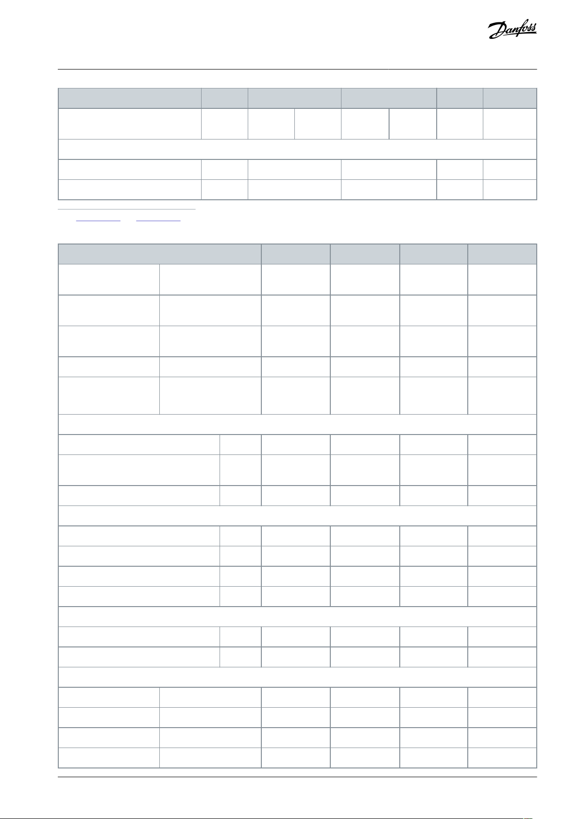
Enclosure size
A1A2A3A4A5
Maximum weight [kg (lb)]
2.7 (6)
4.9 (10.8)
5.3 (11.7)
6.6 (14.6)
7 (15.4)
9.7 (21.4)
13.5/14.2
(30/31)
Front cover tightening torque [Nm (in-lb)]
Plastic cover (low IP)
Click
Click
Click––
Metal cover (IP55/66)
–––
1.5 (13.3)
1.5 (13.3)
Enclosure size
B1B2B3
B4
Rated power [kW (hp)]
200–240 V
5.5–7.5 (7.5–10)
15
5.5–7.5 (7.5–
10)
11–15 (15–20)
380-480/500 V
11–15 (15–20)
18.5–22 (25–30)
11–15 (15–20)
18.5–30 (25–
40)
525–600 V
11–15 (15–20)
18.5–22 (25–30)
11–15 (15–20)
18.5–30 (25–
40)
525–690 V
–
11–22 (15–30)
–
11–30 (15–40)
IP
NEMA
–
21/55/66
Type 1/12/4X
21/55/66
Type 1/12/4X
20
Chassis
20
Chassis
Height [mm (in)]
Height of mounting plate
A
(1)
480 (18.9)
650 (25.6)
399 (15.7)
520 (20.5)
Height with ground termination plate for
fieldbus cables
A––
420 (16.5)
595 (23.4)
Distance between mounting holes
a
454 (17.9)
624 (24.6)
380 (15)
495 (19.5)
Width [mm (in)]
Width of mounting plate
B
242 (9.5)
242 (9.5)
165 (6.5)
230 (9.1)
Width of mounting plate with 1 C option
B
242 (9.5)
242 (9.5)
205 (8.1)
230 (9.1)
Width of mounting plate with 2 C options
B
242 (9.5)
242 (9.5)
225 (8.9)
230 (9.1
Distance between mounting holes
b
210 (8.3)
210 (8.3)
140 (5.5)
200 (7.9)
Depth [mm (in)]
Depth without option A/B
C
260 (10.2)
260 (10.2)
249 (9.8)
242 (9.5)
With option A/B
C
260 (10.2)
260 (10.2)
262 (10.3)
242 (9.5)
Screw holes [mm (in)]
c
12 (0.47)
12 (0.47)
8 (0.31)
–dø19 (ø0.75)
ø19 (ø0.75)
12 (0.47)
–eø9 (ø0.35)
ø9 (ø0.35)
6.8 (0.27)
8.5 (0.33)
f
9 (0.35)
9 (0.35)
7.9 (0.31)
15 (0.59)
VLT® AutomationDrive FC 301/FC 302
Operating Guide
1
See Illustration 21 and Illustration 22.
Table 53: Power Ratings, Weight, and Dimensions, Enclosure Size B
Specifications
AQ267037727118en-000101 / 130R0300 | 85Danfoss A/S © 2021.01

Enclosure size
B1B2B3
B4
Maximum weight [kg (lb)]
23 (51)
27 (60)
12 (26.5)
23.5 (52)
Front cover tightening torque [Nm (in-lb)]
Plastic cover (low IP)
Click
Click
Click
Click
Metal cover (IP55/66)
2.2 (19.5)
2.2 (19.5)
–
–
Enclosure size
C1C2C3C4D3h
Rated power [kW
(hp)]
200–240 V
15–22 (20–30)
30–37 (40–50)
18.5–22 (25–
30)
30–37 (40–
50)
–
380-480/500 V
30–45 (40–60)
55–75 (75–100)
37–45 (50–
60)
55–75 (75–
100)
–
525–600 V
30–45 (40–60)
55–90 (75–125)
37–45 (50–
60)
55–90 (75–
125)
–
525–690 V
–
30–75 (40–100)
37–45 (50–
60)
37–45 (50–
60)
55–75
(75– 100)
IP
NEMA
–
21/55/66
Type 1/12/4X
21/55/66
Type 1/12/4X
20
Chassis
20
Chassis
20
Chassis
Height [mm (in)]
Height of mounting plate
A
(1)
680 (26.8)
770 (30.3)
550 (21.7)
660 (26)
909 (35.8)
Height with ground termination
plate for fieldbus cables
A––
630 (24.8)
800 (31.5)
–
Distance between mounting holes
a
648 (25.5)
739 (29.1)
521 (20.5)
631 (24.8)
–
Width [mm (in)]
Width of mounting plate
B
308 (12.1)
370 (14.6)
308 (12.1)
370 (14.6)
250 (9.8)
Width of mounting plate with 1 C
option
B
308 (12.1)
370 (14.6)
308 (12.1)
370 (14.6)
–
Width of mounting plate with 2 C
options
B
308 (12.1)
370 (14.6)
308 (12.1)
370 (14.6)
–
Distance between mounting holes
b
272 (10.7)
334 (13.1)
270 (10.6)
330 (13)
–
Depth [mm (in)]
Depth without option A/B
C
310 (12.2)
335 (13.2)
333 (13.1)
333 (13.1)
375 (14.8)
With option A/B
C
310 (12.2)
335 (13.2)
333 (13.1)
333 (13.1)
375 (14.8)
Screw holes [mm (in)]
c
12.5 (0.49)
12.5 (0.49)
–––dø19 (ø0.75)
ø19 (ø0.75)
–––eø9 (ø0.35)
ø9 (ø0.35)
8.5 (0.33)
8.5 (0.33)
–
VLT® AutomationDrive FC 301/FC 302
Operating Guide
1
See Illustration 21 and Illustration 22.
Table 54: Power Ratings, Weight, and Dimensions, Enclosure Sizes C & D
Specifications
AQ267037727118en-000101 / 130R030086 | Danfoss A/S © 2021.01

Enclosure size
C1C2C3C4D3hf9.8 (0.39)
9.8 (0.39)
17 (0.67)
17 (0.67)
–
Maximum weight [kg (lb)]
45 (99)
65 (143)
35 (77)
50 (110)
62 (137)
Front cover tightening torque [Nm (in-lb)]
Plastic cover (low IP)
Click
Click
2 (17.7)
2 (17.7)
–
Metal cover (IP55/66)
2.2 (19.5)
2.2 (19.5)
2 (17.7)
2 (17.7)
–
C
a
b
e30ba648.13
f
e
B
A
a
d
e
b
c
a
e
f
e30ba715.12
VLT® AutomationDrive FC 301/FC 302
Operating Guide
1
See Illustration 21 and Illustration 22.
Specifications
Illustration 21: Top and Bottom Mounting Holes
Illustration 22: Top and Bottom Mounting Holes, Enclosure Sizes B4, C3, and C4
AQ267037727118en-000101 / 130R0300 | 87Danfoss A/S © 2021.01

°C
Degrees Celsius
°F
Degrees Fahrenheit
AC
Alternating current
AEO
Automatic energy optimization
AWG
American wire gauge
AMA
Automatic motor adaptation
DC
Direct current
EMC
Electro-magnetic compatibility
ETR
Electronic thermal relay
f
M,N
Nominal motor frequency
I
INV
Rated inverter output current
I
LIM
Current limit
I
M,N
Nominal motor current
I
VLT,MAX
Maximum output current
I
VLT,N
Rated output current supplied by the drive
IP
Ingress protection
LCP
Local control panel
MCT
Motion control tool
nsSynchronous motor speed
P
M,N
Nominal motor power
PELV
Protective extra low voltage
PCB
Printed circuit board
PM motor
Permanent magnet motor
PWM
Pulse width motor
RPM
Revolutions per minute
Regen
Regenerative terminals
T
LIM
Torque limit
U
M,N
Nominal motor voltage
VLT® AutomationDrive FC 301/FC 302
Operating Guide
9 Appendix
9.1 Symbols and Abbreviations
Appendix
AQ267037727118en-000101 / 130R030088 | Danfoss A/S © 2021.01

VLT® AutomationDrive FC 301/FC 302
Operating Guide
Index
+
+10 V DC output...........................................................................................74
2
24 V DC output..............................................................................................74
A
Abbreviations................................................................................................ 88
AC input...........................................................................................................19
AC mains..........................................................................................................19
Access panel...................................................................................................18
Additional resources......................................................................................6
Air cooling.......................................................................................................13
Alarm.................................................................................................................43
Alarms
List of....................................................................................................... 44
AMA...................................................................................................................24
Ambient conditions
Specifications........................................................................................71
Analog input.................................................................................................. 73
Analog output............................................................................................... 74
Approvals and certifications.......................................................................7
Automatic motor adaptation
Wiring example....................................................................................26
Preventing motor overheating...................................................... 46
Alarms......................................................................................................54
Auxiliary equipment....................................................................................20
B
Backplate.........................................................................................................14
Brake resistor...........................................................................................49, 49
Brake terminal..................................................................................................7
Brake wiring configuration....................................................................... 39
Burst transient............................................................................................... 16
C
Cable length, control cables.....................................................................72
Cable routing................................................................................................. 20
Cable specifications.....................................................................................72
Circuit breaker............................................................................................... 76
Circuit breakers............................................................................................. 21
Closed loop
Basic set-up............................................................................................25
Control card...............................................................................74, 74, 74, 74
Control card performance.........................................................................75
Control characteristics................................................................................75
Control wiring...........................................................................15, 19, 20, 21
Cooling.............................................................................................................13
Cooling clearance..................................................................................13, 21
Cooling requirements.................................................................................13
Cross-section, control cable..................................................................... 72
D
DC overvoltage............................................................................................. 45
Design guide..................................................................................................71
Digital input....................................................................................................72
Digital output................................................................................................ 74
Dimensions, enclosure size A...................................................................84
Dimensions, enclosure size B...................................................................85
Index
Dimensions, enclosure sizes C and D....................................................86
Disconnect switch........................................................................................22
E
Electro-mechanical brake..........................................................................20
EMC-compliant installation............................................................... 15, 16
EN 60664-1......................................................................................................75
EN 61800-3......................................................................................................71
EN60664-1.......................................................................................................70
Encoder feedback.........................................................................................24
Encoder input................................................................................................ 73
Energy efficiency class................................................................................71
Environment.................................................................................................. 71
Exploded view..................................................................................................7
External alarm reset.....................................................................................35
External controller.......................................................................................... 6
External interlock...................................................................................31, 55
F
Fans
Internal fault..........................................................................................48
External fault.........................................................................................49
Mixing fan fault.................................................................................... 58
Feedback......................................................................................................... 20
Fieldbus
Warning.................................................................................................. 50
Floating delta.................................................................................................19
Front cover tightening torque, enclosure size A.............................. 85
Front cover tightening torque, enclosure size B...............................86
Front cover tightening torque, enclosure sizes C and D................87
Fuse..................................................................................................... 15, 21, 76
Fuses
Warning.................................................................................................. 51
G
GLCP..................................................................................................................23
Ground connection..................................................................................... 21
Ground wire....................................................................................................15
Grounded delta.............................................................................................19
Grounding.........................................................................................19, 21, 22
Grounding principle....................................................................................16
H
Heat sink............................................................................................ 49, 49, 52
Hoisting application....................................................................................20
I
IEC 60068-2-43.............................................................................................. 71
IEC 60364.........................................................................................................76
IEC 61800-3..............................................................................................19, 71
IEC 721-3-3......................................................................................................71
Input current..................................................................................................19
Input disconnect...........................................................................................19
Input power...............................................................................15, 19, 22, 43
Input power wiring......................................................................................21
Input terminal.........................................................................................19, 22
Installation check list...................................................................................20
Installation environment...........................................................................13
Intended use................................................................................................ 6, 6
AQ267037727118en-000101/130R0300 | 89Danfoss A/S © 2021.01

VLT® AutomationDrive FC 301/FC 302
Operating Guide
Interference isolation..................................................................................20
Isolated mains................................................................................................19
Items supplied...............................................................................................12
K
Knockout......................................................................................................... 18
L
LCP.....................................................................................................................23
Leakage current..................................................................................... 10, 15
Lifting................................................................................................................14
List of warnings and alarms......................................................................44
M
Mains
Mains connection................................................................................19
Warning............................................................................................ 45,51
Mains supply, 200–240 V............................................................. 60, 60, 61
Mains supply, 380–500 V............................................................. 62, 63, 64
Mains supply, 525–600 V............................................................. 65, 65, 66
Mains supply, 525–690 V............................................................. 67, 68, 69
Maintenance.................................................................................................. 43
Mechanical brake control............................................................20, 39, 47
Motor
Thermal protection.............................................................................15
Motor power......................................................................................... 15
Wiring thermistor................................................................................37
Warning.......................................................................... 46,46,50,50,50
Motor cable............................................................................................. 15, 82
Motor output................................................................................................. 71
Motor overload protection..........................................................................6
Motor status......................................................................................................6
Motor terminal.................................................................................................7
Motor wiring.................................................................................................. 20
Mounting.........................................................................................................14
Mounting plate............................................................................................. 14
N
Nameplate...................................................................................................... 12
NEC 2009......................................................................................................... 76
O
Open-loop speed control configurations............................................27
Output power wiring.................................................................................. 21
Output terminal............................................................................................ 22
Overcurrent protection..............................................................................15
Index
R
Railings.............................................................................................................14
Regen
Wiring configuration..........................................................................37
Relay output...................................................................................................75
Remote commands........................................................................................6
Reset....................................................................................................43, 43, 56
RFI filter............................................................................................................ 19
RS485................................................................................................................ 36
RS485 serial communication....................................................................74
Run/stop command.................................................................................... 32
Run/stop wiring configuration................................................................31
S
Safe Torque Off............................................................................................. 19
See STO
Safe torque off
Wiring of................................................................................................. 33
Service.............................................................................................................. 43
Shielded cable........................................................................................ 18, 21
Shock................................................................................................................ 13
Short circuit
Alarm....................................................................................................... 47
Speed reference............................................................................................27
Start/stop command...................................................................................33
STO...........................................................................17, 19, 56, 56, 56, 57, 72
Storage.............................................................................................................12
Supply voltage.................................................................................19, 22, 70
Surveillance.......................................................................................................6
Switches
Disconnect......................................................................................... 9,43
Symbols.......................................................................................................9, 88
System feedback.............................................................................................6
System set-up................................................................................................ 24
T
Thermal protection........................................................................................ 8
Thermistor
Wiring configuration....................................................................37,37
Warning.................................................................................................. 57
Thermistor control wiring......................................................................... 19
Torque
Warning.................................................................................................. 46
Torque characteristics................................................................................ 71
Trip.....................................................................................................................43
Trip lock............................................................................................................43
Troubleshooting...........................................................................................44
P
PELV...................................................................................................................37
Phase imbalance...........................................................................................51
Power factor correction capacitor..........................................................20
Power rating, enclosure size B.................................................................85
Power ratings, enclosure size A...............................................................84
Power ratings, enclosure sizes C and D................................................86
Power wire connection.............................................................................. 15
Pulse input......................................................................................................73
Pulse start/stop wiring configuration................................................... 34
Q
Qualified personnel...................................................................................6, 9
U
UL certification.................................................................................................7
Unintended start......................................................................................9, 43
USB serial communication........................................................................74
V
Vibration..........................................................................................................13
Voltage
Safety warning.......................................................... 9,22,48,50,50,50
Voltage level...................................................................................................72
AQ267037727118en-000101/130R030090 | Danfoss A/S © 2021.01

VLT® AutomationDrive FC 301/FC 302
Operating Guide
W
Warning........................................................................................................... 43
Warnings
List of....................................................................................................... 44
Website...............................................................................................................6
Weight, enclosure size A............................................................................84
Weight, enclosure size B............................................................................ 85
Weight, enclosure sizes C and D.............................................................86
Wire size...........................................................................................................15
Index
Wire type and ratings..................................................................................15
Wiring configurations
Open loop.............................................................................................. 27
Start/stop............................................................................................... 33
External alarm reset............................................................................35
Thermistor..............................................................................................37
Regen.......................................................................................................37
Wiring schematic..........................................................................................17
AQ267037727118en-000101/130R0300 | 91Danfoss A/S © 2021.01

Danfoss A/S
Ulsnaes 1
DK-6300 Graasten
vlt-drives.danfoss.com
Danfoss can accept no responsibility for possible errors in catalogs, brochures and other printed material. Danfoss reserves the right to alter its products without notice. This
also applies to products already on order provided that such alterations can be made without subsequential changes being necessary in specifications already agreed. All
trademarks in this material are property of the respective companies. Danfoss and the Danfoss logotype are trademarks of Danfoss A/S. All rights reserved.
*130R0300*
Danfoss A/S © 2021.01
AQ267037727118en-000101 / 130R0300
*M0012501*
 Loading...