

Page 1

Contents
2. Introduction
5
About this Manual 5
Technical Overview 5
Assumptions 5
Hardware 5
Background Knowledge 5
Abbreviations 6
3. How to Install
7
Cabling 7
Installation of Option 8
LEDs 10
Configure the FC 300 11
4. How to Configure the System
13
Configure the Interbus Network 13
5. How to Control the FC 300
17
Process Data 17
The Drivecom State Machine 21
Drivecom 21 Control Profile 24
Danfoss FC Control Profile 26
6. How to Access the FC 300 Parameters
31
PCP Communication 31
7. Parameters
33
Data Types Supported by FC 300 39
8. Troubleshooting
41
LED Behaviour Stopped Interbus Comm. 43
Index
44
FC 300 Interbus Operating Instructions Contents
MG.33.H3.02 - VLT is a registered Danfoss trademark
1
Page 2

1. Safety Note - FC 300 Interbus FC 300 Interbus Operating Instructions
2
MG.33.H3.02 - VLT is a registered Danfoss trademark
1
Page 3

1.1.1. Copyright, Limitation of Liability and Revision Rights
This publication contains information proprietary to Danfoss A/S. By accepting and using this manual the user agrees that the information contained
herein will be used solely for operating equipment from Danfoss A/S or equipment from other vendors provided that such equipment is intended for
communication with Danfoss equipment over an Interbus serial communication link. This publication is protected under the Copyright laws of Denmark
and most other countries.
Danfoss A/S does not warrant that a software program produced according to the guidelines provided in this manual will function properly in every
physical, hardware or software environment.
Although Danfoss A/S has tested and reviewed the documentation within this manual, Danfoss A/S makes no warranty or representation, either express
or implied, with respect to this documentation, including its quality, performance, or fitness for a particular purpose.
In no event shall Danfoss A/S be liable for direct, indirect, special, incidental, or consequential damages arising out of the use, or the inability to use
information contained in this manual, even if advised of the possibility of such damages. In particular, Danfoss A/S is not responsible for any costs including
but not limited to those incurred as a result of lost profits or revenue, loss or damage of equipment, loss of computer programs, loss of data, the costs
to substitute these, or any claims by third parties.
Danfoss A/S reserves the right to revise this publication at any time and to make changes in its contents without prior notice or any obligation to notify
previous users of such revisions or changes.
FC 300 Interbus Operating Instructions 1. Safety Note - FC 300 Interbus
MG.33.H3.02 - VLT is a registered Danfoss trademark
3
1
Page 4

1.2. Safety Note
The voltage of the frequency converter is dangerous whenever connected to mains. Incorrect installation of the motor, frequency
converter or fieldbus may cause damage to the equipment, serious personal injury or death. Consequently, the instructions in this
manual, as well as national and local rules and safety regulations, must be complied with.
1.2.1. Safety Regulations
1. The frequency converter must be disconnected from mains if repair work is to be carried out. Check that the mains supply has been disconnected
and that the necessary time has passed before removing motor and mains plugs.
2. The [OFF] key on the control panel of the frequency converter does not disconnect the equipment from mains and is thus not to be used as a
safety switch. 3. Correct protective earthing of the equipment must be established, the user must be protected against supply voltage, and the
motor must be protected against overload in accordance with applicable national and local regulations.
3. Correct protective earthing of the equipment must be established, the user must be protected against supply voltage, and the motor must be
protected against overload in accordance with applicable national and local regulations.
4. The earth leakage currents are higher than 3.5 mA.
5. Protection against motor overload is not included in the factory setting. If this function is desired, set par. 1-90 Motor
Thermal Protection
to
data value
ETR trip
or data value
ETR warning
. Note: The function is initialised at 1.16 x rated motor current and rated motor frequency. For
the North American market: The ETR functions provide class 20 motor overload protection in accordance with NEC.
6. Do not remove the plugs for the motor and mains supply while the frequency converter is connected to mains. Check that the mains supply has
been disconnected and that the necessary time has passed before removing motor and mains plugs.
7. Please note that the frequency converter has more voltage inputs than L1, L2 and L3, when load sharing (linking of DC intermediate circuit) and
external 24 V DC have been installed. Check that all voltage inputs have been disconnected and that the necessary time has passed before
commencing repair work.
1.2.2. Warning Against Unintended Start
1. The motor can be brought to a stop by means of digital commands, bus commands, references or a local stop, while the frequency converter
is connected to mains. If personal safety considerations make it necessary to ensure that no unintended start occurs, these stop functions are
not sufficient.
2. While parameters are being changed, the motor may start. Consequently, the stop key [STOP/RESET] must always be activated; following which
data can be modified.
3. A motor that has been stopped may start if faults occur in the electronics of the frequency converter, or if a temporary overload or a fault in
the supply mains or the motor connection ceases.
1.2.3. Warning
Touching the electrical parts may be fatal - even after the equipment has been disconnected from mains.
Also make sure that other voltage inputs have been disconnected, such as external 24 V DC, load sharing (linkage of DC intermediate circuit), as well as
the motor connection for kinetic back up.
Please refer to the relevant Operating Instructions for further safety guidelines.
1. Safety Note - FC 300 Interbus FC 300 Interbus Operating Instructions
4
MG.33.H3.02 - VLT is a registered Danfoss trademark
1
Page 5

2. Introduction
2.1.1. About this Manual
First time users can obtain the most essential information for quick installation and set-up in these chapters:
Introduction
How to Install
How to Configure the System
For more detailed information including the full range of set-up options and diagnosis tools please refer to the chapters:
How to Control the FC 300
How to Access FC 300 Parameters
Parameters
Troubleshooting
2.2.1. Technical Overview
The Interbus system is divided into two different systems: remote and local.
The remote system enables the user to connect up to 256 stations on a single system with a maximum of 400m cable length between stations.
The local bus system enables the user to establish communication to Input/Output devices through a single twisted pair of Cables. This type of commu-
nication typical uses simple devices, e.g. Digital I/O devices.
The Interbus option described in this manual supports remote bus only. For communication on the remote bus, the Interbus system provides two different
types of communication: Process Data and PCP (Peripherals Communication Protocol). The Process Data is cyclic communication to devices with high
priority.
Examples of this type of communication are digital and analogue I/O or control word and reference to frequency converters.
PCP communication is used for communications which do not require high speed and typically only are activated on request from the user-written program.
Typical time to read/write a single value is 100 to 200 milliseconds. Examples of this type of communication are configuration data, or reading of service
parameters such as running hours, numbers of power ups and kWh.
2.3.1. Assumptions
This manual assumes that you are using a Danfoss Interbus Option in conjunction with a Danfoss FC 300 Automation Drive. It is also assumed that your
master is a PLC or PC that is equipped with a serial communication card supporting all the Interbus communication services required by your application,
and that all requirements stipulated in the Interbus standard as well as those set up in the Drivecom frequency converter Profile and its company-specific
implementation, as well as those pertaining to the VLT frequency converter are strictly observed as well as all limitations therein fully respected.
2.4.1. Hardware
This manual relates to the Interbus option type no. 130B1211.
2.5.1. Background Knowledge
The Danfoss Interbus Option is designed to communicate with any master abiding by the Interbus standard. It is therefore assumed that you have full
knowledge of the PC or PLC you intend to use as a master in your system. Any questions pertaining to hardware or software produced by any other
manufacturer are beyond the scope of this manual and are of no concern to Danfoss.
If you have questions about how to set up master-to-master communication or communication to a non-Danfoss slave, please consult the appropriate
manuals.
FC 300 Interbus Operating Instructions 2. Introduction
MG.33.H3.02 - VLT is a registered Danfoss trademark
5
2
Page 6

The following literature is available for the , 200 and series.
Title
Literature no.
Operating Instructions MG.11.AX.YY
Design Guide MG.11.BX.YY
Programming Guide MG.11.CX.YY
VLT AQUA Drive FC 200 Operating Instructions MG.20.NX.YY
VLT AQUA Drive FC 200 Design Guide MG.20.MX.YY
VLT AQUA Drive FC 200 Programming Guide MG.20.OX.YY
VLT AutomationDrive FC 300 Operating Instructions MG.33.AX.YY
VLT AutomationDrive FC 300 Design Guide MG.33.BX.YY
VLT AutomationDrive FC 300 Programming Guide MG.33.MX.YY
VLT AutomationDrive , 200 and 300 PROFIBUS Operating Instructions MG.33.CX.YY
VLT AutomationDrive , 200 and 300 DeviceNet Operating Instructions MG.33.DX.YY
VLT AutomationDrive FC 300 MCT 10 Software Dialogue MG.33.EX.YY
PROFIBUS DP V1 Design Guide MG.90.EX.YY
2.7.1. Abbreviations
ACK ACKnowledge
BOOL Boolean
CTW Control Word
EDS Electronic Data Sheet
EMC Electromagnetic Compatibility
HF High Frequency
HPFB High Performance Field Bus
IBS Interbus
I/O Input/Output
LCD Liquid Crystal Display
LCP Local Control Panel
LED Light Emitting Diode
LSB Least Significant Bit
MSB Most Significant Bit
MAV Main Actual Value
MRV Main Reference Value
N/A Not applicable
PC Personal Computer
PCD Process Data
PCP Peripherals Communication Protocol
PIW Peripheral input word
PLC Programmable Logic Control
PNU Parameter NUmber
PPO Parameter-Process Data Object
SINT Signed integer
STW Status Word
VSD Variable Speed Drive
UDINT Unsigned double integer
UNIT Unsigned integer
2. Introduction FC 300 Interbus Operating Instructions
6
MG.33.H3.02 - VLT is a registered Danfoss trademark
2
Page 7

3. How to Install
3.1.1. Cabling
The Interbus network topology is based on a logical ring structure, implemented in a one-cable structure, making a physical bus structure with a bit rate
of 500 kbps.
Interbus supports networks with a total cable length of up to 12.8 km, with a maximum of 400 meters between nodes.
The maximum cable length is only achievable when the bus cable has the following properties:
Impedance: 120 ohm ±20% @ 64kHz, 100 ohm ±15% @ >1 MHz.
Resistance: < 9.6 ohm/100 m
Capacity: < 60 nF/km
Cross section: minimum 0.2 mm2, corresponding to AWG 25
Cable type: twisted in pairs, 3 x 2 wires
Screening: Copper-braided screen or braided screen and foil screen
Use of the same cable type throughout the entire network is recommended in order to avoid impedance mismatch.
The Interbus option has two network interfaces, one for the incoming bus and one for the outgoing bus. Both are D-sub 9 type.
FC 300 Interbus Operating Instructions 3. How to Install
MG.33.H3.02 - VLT is a registered Danfoss trademark
7
3
Page 8

3.2.1. EMC Precautions
The following EMC precautions are recommended in order to achieve interference-free operation of the Interbus network. Additional EMC information is
available in the FC 300 series Operating Instructions (MG33AXYY) and Design Guide (MG33BXYY).
NB!
Relevant national and local regulations, for example regarding protective earth connection, must be observed.
The Interbus communication cable must be kept away from motor and brake resistor cables to avoid coupling of high frequency noise from one cable to
the other. Normally a distance of 200 mm (8 inches) is sufficient, but maintaining the greatest possible distance between the cables is recommended,
especially where cables run in parallel over long distances. If the Interbus cable has to cross a motor and brake resistor cable they must cross each other
at an angle of 90 degrees.
3.3.1. Installation of Option
The Interbus option is installed in its own cabinet, designed for DIN-rail mounting.
The option is connected to the FC 302 via terminal X22 on the option to terminal 68 and 69 on the frequency converter. Screened cable is recommended
(120 cm cable supplied with frequency converter).
3. How to Install FC 300 Interbus Operating Instructions
8
MG.33.H3.02 - VLT is a registered Danfoss trademark
3
Page 9

The RS-485 termination switch on the FC 300 (BUS-TER.) must be set to “ON”.
Interbus option FC 302
X22-1 61 (RS 485 com)
X22-2 68 (RS 485 +)
X22-3 69 (RS 485 -)
X22-4 chassis on FC 300
NB!
Grounding of the Interbus option is mandatory and can be achieved in several ways:
- Via the DIN-rail
- Via the connections X23-4 or X22-4
3.3.2. I/O Specifications
X22: FC-bus X23: Power supply X24+25: Digital I/O
RS-485 Voltage level: 24 V dc ± 15%
Current consumption: max. 160 mA excluding load on digital outputs.
Digital inputs:
Voltage level: 0-24 V DC
Voltage level, logic “0”:< 5 V DC
Voltage level, logic “1”:> 9 V DC
Maximum input voltage: 28 V DC
Minimum input voltage: -28 V DC
Frequency range: DC to 250 Hz
Duty cycle min. pulse width: 2 ms
Input resistance: approx. 4 kΩ
Digital outputs:
Voltage level: 0-24 V DC (open collector
PNP) short-circuit protected.
Maximum output current: 25 mA
FC 300 Interbus Operating Instructions 3. How to Install
MG.33.H3.02 - VLT is a registered Danfoss trademark
9
3
Page 10

3.3.3. General Specifications
Operating temperature ÷10 - +55°C
Max. relative humidity 5% - 95% non condensing
Enclosure IP 20
3.4.1. LEDs
Name Colour Indicates ON OFF
Out 1 - Out 2 Green State of outputs* Output high Output low
In 1 - In 4 Green State of inputs Input high Input low
FC BUS Green Activity on FC-Bus
RD Red Status of outgoing bus Out. bus stopped Out. bus active
TR Green Transmit/Receive PCP comm. running No PCP comm.
BA Green Bus Active Bus active Bus stopped
CC Green Cable check Incoming bus active Incoming bus off
UL Green Power O.K. Voltage O.K. No voltage
*= Flashing by external short circuit.
3. How to Install FC 300 Interbus Operating Instructions
10
MG.33.H3.02 - VLT is a registered Danfoss trademark
3
Page 11

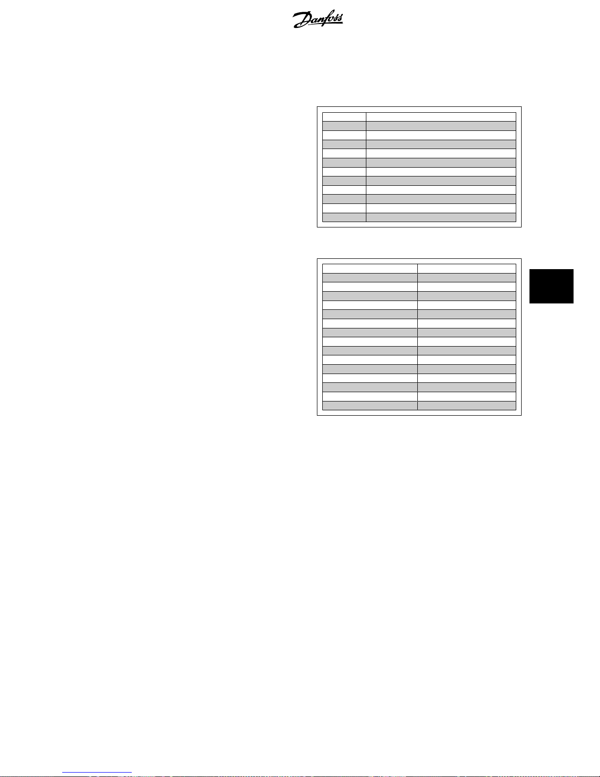
3.5. Configure the FC 300
3.5.1. VLT Parameters
Pay particular attention to the following parameters when configuring an FC 300 with an Interbus interface. Please refer to the
Parameters
chapter for
more details of each parameter.
3.5.2. Basic Communication Parameters
These parameters are necessary to establish communication between the Interbus option and the FC 300.
Parameter Parameter name Setting
8-01 Control Site [0] Control Word only
8-32 FC Port Baud Rate [4] 38400 baud
8-35 Minimum Response Delay 1 ms
The Interbus option is capable of operating with two different telegram-types for process data:
• Standard Telegram 1, is a telegram with 4 PCD’s. The two first PCD’s is for holding Control word and reference for Master-to-slave comm. And
Status word and Main Actual Value for Slave-to-master comm. The last two PCD’s (3 and 4) is reserved for future use, and contains only 0’s.
• Custom Telegram 1, is a telegram with 4 PCD’s that in addition also holds information on digital and analogue I/O’s and torque limit.
3.5.3. Standard Telegram 1
In order to interface with the Interbus option, running Standard Telegram 1, the following parameters must be set on the FC 300:
Parameter Parameter name Setting
8-40 Telegram Selection [1] Standard Telegram 1
3-15 Reference Resource 1 [0] No Function
3-16 Reference Resource 2 [0] No Function
8-10 Control Word Profile [0] FC profile
[1] PROFIdrive profile (= Drivecom)
NB!
Setting par. 8-10 to [1] PROFIdrive profile, enables the Drivecom Profile on the Interbus option, i.e. Control word and Status word are
interpreted as Drivecom.
Setting par. 8-10 to [0] FC Profile will enable the FC profile on the frequency converter.
See section
How to Control the FC 300
for more information on the different profiles.
FC 300 Interbus Operating Instructions 3. How to Install
MG.33.H3.02 - VLT is a registered Danfoss trademark
11
3
Page 12

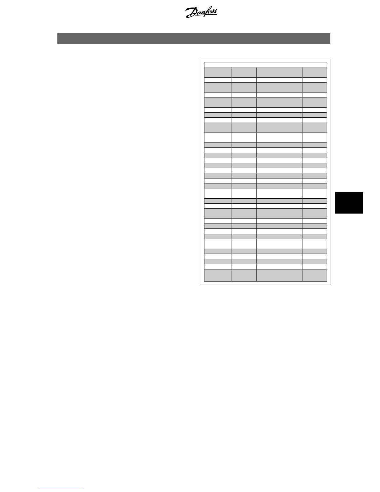
3.5.4. Custom Telegram 1
In order to interface with the Interbus option, running Custom Telegram 1, the following parameters must be set on the FC 300:
Parameter Parameter name Setting
8-40 Telegram Selection [200] Custom Telegram 1
3-15 Reference Resource 1 [0] No Function
3-16 Reference Resource 2 [0] No Function
5-01 Terminal 27 mode [1] Output
5-02 Terminal 29 mode [1] Output
5-10 Terminal 18 Digital Input [0] No Operation
5-11 Terminal 19 Digital Input [0] No Operation
5-12 Terminal 27 Digital Input [0] No Operation
5-15 Terminal 33 Digital Input [0] No Operation
5-30 Terminal 27 Digital Output [45] Bus controlled
[46] Bus controlled, 1 if timeout
[47] Bus controlled, 0 if timeout
5-31 Terminal 29 Digital Output [45] Bus controlled
[46] Bus controlled, 1 if timeout
[47] Bus controlled, 0 if timeout
5-40 [0] Function Relays, Relay 1 [45] Bus controlled
[46] Bus controlled, 1 if timeout
[47] Bus controlled, 0 if timeout
5-40 [1] Function Relays, Relay 2 [45] Bus controlled
[46] Bus controlled, 1 if timeout
[47] Bus controlled, 0 if timeout
8-10 Control Word Profile [0] FC profile
[1] PROFIdrive profile (= Drivecom)
NB!
If the Interbus option is powered up without connection to a FC300 frequency converter, it will run Standard Telegram 1.
This means that it will not be possible to use any I/O’s.
NB!
For the digital- and relay-outputs the reaction in case of a bus-timeout can be selected.
Bus ctrl. [45]: The output is controlled via bus. In case of a bus-timeout the output state is kept at the last known state.
Bus ctrl. 1 if timeout [46]: The output is controlled via bus. In case of a bus-timeout the output state is set to logical 1.
Bus ctrl. 0 if timeout [47]: The output is controlled via bus. In case of a bus-timeout the output state is set to logical 0.
NB!
Setting par. 8-10 to [1]
PROFIdrive profile
, enables the Drivecom Profile on the Interbus option, i.e. Control word and Status word are
interpreted as Drivecom.
Setting par. 8-10 to [0]
FC Profile
will enable the FC profile on the frequency converter.
See section
How to Control the FC 300
for more information on the different profiles.
NB!
Par. 0-40 [Hand on] key on LCP.
If the Hand button on the FC 300 is activated, control of the frequency converter via the Interbus interface is disabled.
3. How to Install FC 300 Interbus Operating Instructions
12
MG.33.H3.02 - VLT is a registered Danfoss trademark
3
Page 13

4. How to Configure the System
4.1.1. Configure the Interbus Network
This section describes how to set up Interbus communication between a Danfoss FC 300 frequency converter and the Phoenix Interbus CMD G4.
4.1.2. Configuring of the CMD and FC 300
The first step is to connect all Interbus slaves to the master and power
up all units. Start the IBS CMD software and choose a new project from
File and New. The screen should now look like this:
The next step is to read the slaves into the bus system. Click on Config-
uration frame and click on the right mouse button. Select Read In (from
memory).
The state will be changed from Offline to Online when the Read In is
finished. Please look at the bottom of the screen. After the Read In, CMD
will indicate each VLT frequency converter with a DriveCom symbol, a
station number and an ID number.
The next step is to configure the Interbus system. This is done by clicking
on the VLT symbol and pressing the right mouse button. Select:
Descrip-
tion
.
Here it is possible to type in a Station name, Device name and a Device
number. Click on:
Parameter Channel
.
For message length transmit and receive enter 246 byte and select Get-
OD (long format). The message length now corresponds to the internal
buffer in the VLT frequency converter. Get-OD (long format) means that
the master will read the English parameter description text from the VLT
frequency converter. Press OK twice.
FC 300 Interbus Operating Instructions 4. How to Configure the System
MG.33.H3.02 - VLT is a registered Danfoss trademark
13
4
Page 14

4.1.3. Setting up PCP Communication
Via the CMD tool it is possible to read and write to parameters, and read
the English parameter text of each parameter.
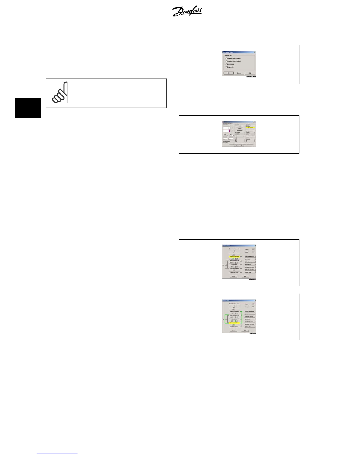
To start PCP communication you must be in Monitor state.
Click on the station number and click on the right mouse button and
choose: Device
Parameterization
.
The dialog box will now show Danfoss, VLT FC 300, Profile: 21.
In order to be able to read all parameters into the frequency converter,
select:
Device and Read Parameter List
.
The CMD tool will now start reading all parameters, which takes 3-4 mi-
nutes.
When all parameters have been read, CMD will show the first parameter
55F1hex Par. 1 at the first row.
55F1hex corresponds to 22001dec.
This means that all FC 300 parameters can be accessed simply by adding
22000dec to the FC 300 parameter.
For example if you want to write to par. 3-41
Ramp 1 ramp up time
, you
must write to 22341dec (5745hex).
The CMD tool can only indicate parameters using hexadecimal numbers.
The two first indexes are for handling the “Max Torque Limit” (par. 4-16
and 4-17) when running Custom Telegram 1.
If yo u want to chan ge the va lue of par. 3- 41
Ramp 1 ramp up time
to 10
sec you must write 1000 in column next to index 5745 Hex.
You have to enter 1000 because par. 3-41 has a conversion index of -2
(= 0.01). Highlight the row and click on F5 Write Value.
The ramp up time in par. 3-41 has now been changed to 10 sec.
To activate the new settings with PCD, the CMD needs to read the con-
figuration from the VLT frequency converter again.
Click on the controller board and select Process data. The Process data
should now be 64 bits, corresponding to 4 words: control word, reference,
PCD 1 and PCD 2.
4. How to Configure the System FC 300 Interbus Operating Instructions
14
MG.33.H3.02 - VLT is a registered Danfoss trademark
4
Page 15

When the system is running, change the state to:
Monitor
.
Click on the controller board and select:
Address Monitor
.
The Address Monitor shows the I/O area.
E0 Input:
Shows the status word from the frequency converter.
A0 Output:
Is used for sending the control word to the frequency converter.
E2 Input:
Shows the actual output frequency of the frequency converter.
A2 Output:
This I/O area is used to send a speed reference to the frequency con-
verter.
N.B:
Custom Telegram 1 only ! For Standard
telegram 1 the below I/O’s contain no
data.
E4 Input (PCD 3 read):
This I/O area reads the digital inputs. (See section:
Process
Data
.)
A4 Output (PCD 4 write):
Writes settings to digital outputs. (See section:
Process Da-
ta
.)
E6 Input (PCD 3 read):
This I/O area reads the analogue inputs. (See section:
Process Data
.)
A6 Output (PCD 4 write):
This I/O area is used to send a torque limit to the frequency
converter. (See section:
Process Data
.)
NB!
I/O area: E/A 4 to 6 apply only for Custom Telegram 1.
For Standard Telegram 1 these I/O’s contains no data.
See section
How to Control the FC 300
for more information on the different profiles.
The frequency converter is now set up and the program can be down-
loaded to the PLC master.
This is done by clicking with the right mouse button on the Controller
board.
Select:
Parameterization
and
Execute
.
After the parameterization is done, the master will start to run. If you are
using a Siemens S7 or S5 master, the LCD will look like this:
FC 300 Interbus Operating Instructions 4. How to Configure the System
MG.33.H3.02 - VLT is a registered Danfoss trademark
15
4
Page 16
4.1.4. Drivecom Profile
The Interbus option has implemented the Drivecom control profile.
By changing the operating state from Online to Monitor it is possible to
write the control word and reference to the frequency converter. In Mon-
itor mode it is also possible to read and write to parameters.
NB!
The Drivecom profile is only active if the PROFIdrive
profile has been selected in par. 8-10
Control Word
Profile
.
Now the built in Drivecom monitor in the CMD tool can be started by right-
clicking on the controller board and selecting
Drivecom
.
The Drivecom monitor will now show Danfoss, VLT FC 300, Profile: 21,
in the upper left corner.
The Drivecom monitor is split up into three parts:
Analog Display, Control Word and Status word.
In the Analog Display part the reference can be set.
In the Control word part, start and stop-commands can be send to the
frequency converter.
In the Status word part the actual status word from the frequency con-
verter is read out. By clicking Settings you can setup the Drivecom
monitor.
Click on Device Control to begin controlling the VLT frequency converter.
Please note that the control word will change when the state changes.
Click 4 for Ready to Switch On and click 2 for Switch On.
Upon clicking 5 the VLT frequency converter should start the motor.
The control word is now 7F Hex.
Press Close.
4. How to Configure the System FC 300 Interbus Operating Instructions
16
MG.33.H3.02 - VLT is a registered Danfoss trademark
4
Page 17
5. How to Control the FC 300
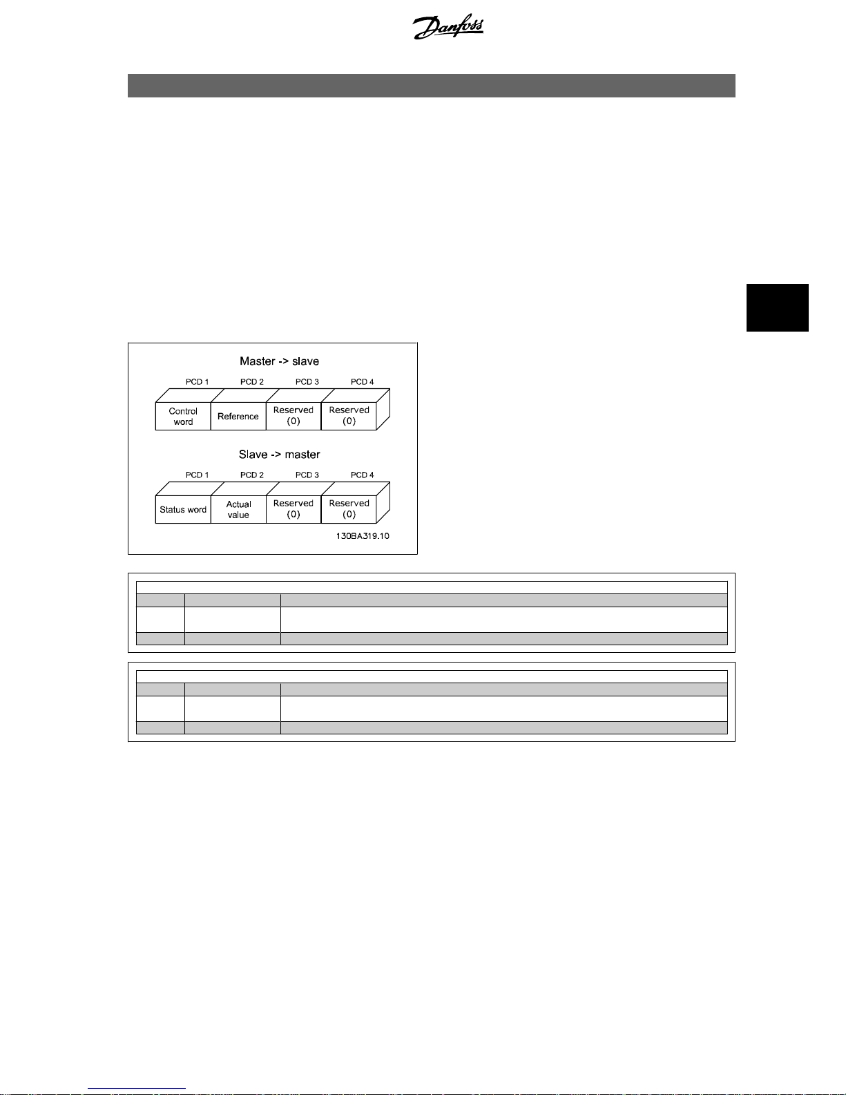
5.1.1. Process Data
The Process Data provides an agile way of controlling the FC 300 frequency converter. Two different telegram-types are for process data are supported:
• Standard Telegram 1, is a telegram with 4 PCD’s. The two first PCD’s is for holding Control word and reference for Master-to-slave comm. And
Status word and Main Actual Value for Slave-to-master comm. The last two PCD’s (3 and 4) is reserved for future use, and contains only 0’s.
• Custom Telegram 1, is a telegram with 4 PCD’s that in addition also holds information on digital and analogue I/O’s and torque limit.
See section
How to Install
for more information on how to select the different telegram profiles.
5.1.2. Standard Telegram 1
The Process Data length is fixed to 4 words, each of two bytes, with the following format:
Master slave→
PCD Name Function
1 Control Word Sends the Control Word to the frequency converter. The format depends of the setting of par.
8-10.
2 Reference Sends the reference in %. See section:
Bus speed reference value
.
Slave master→
PCD Name Function
1 Status Word Sends the Status word from the frequency converter. The format depends of the setting of par.
8-10.
2 Actual value Sends actual output frequency in %. See section:
Bus speed reference Value
.
FC 300 Interbus Operating Instructions 5. How to Control the FC 300
MG.33.H3.02 - VLT is a registered Danfoss trademark
17
5
Page 18
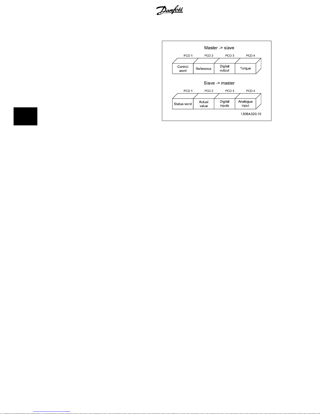
5.1.3. Custom Telegram 1
The Process Data length is fixed to 4 words, each of two bytes, with the
following format:
5. How to Control the FC 300 FC 300 Interbus Operating Instructions
18
MG.33.H3.02 - VLT is a registered Danfoss trademark
5
Page 19
Master slave→
PCD Name Function
1 Control Word Sends the Control Word to the frequency converter. The format depends of the setting of par.
8-10.
2 Reference Sends the reference in %. See section:
Bus speed reference value
.
3 Digital outputs
(bit=1 output=high)→
Bit 0: Output 27
Bit 1: Output 29
Bit 2: Relay 1
Bit 3: Relay 2
Bit 4-13: Reserved
Bit 14: Output DOUT 1 (X25-2) on Interbus option
Bit 15: Output DOUT 2 (X25-3) on Interbus option
4 Torque Sets torque limits in Motor and Generator mode, par. 4-16 and 4-17.
N.B.: A value of “0” (zero) is not accepted, but discarded by the option.
FC 300 Interbus Operating Instructions 5. How to Control the FC 300
MG.33.H3.02 - VLT is a registered Danfoss trademark
19
5
Page 20
Slave master→
PCD Name Function
1 Status Word Sends the Status word from the frequency converter. The format depends of the setting of
par. 8-10.
2 Actual value Sends actual output frequency in %. See section:
Bus speed reference Value
.
3 Digital inputs (bit=1 →
input=high)
Bit 0: Input 33
Bit 1: Input 32
Bit 2: Input 29
Bit 3: Input 27
Bit 4: Input 19
Bit 5: Input 18
Bit 6-11: Reserved
Bit 12: Input DIN 1 (X25-1) on Interbus option
Bit 13: Input DIN 2 (X24-2) on Interbus option
Bit 14: Input DIN 3 (X24-3) on Interbus option
Bit 15: Input DIN 4 (X24-4) on Interbus option
4 Analogue input Reads out analogue input 53 as an absolute value. Term.53 can work as a voltage (0-10V) or
a current (0-20mA) input, depending on the setting of S201.
S201=0 voltage, S201=1 current.→→
NB!
If the connection to the Interbus master is lost, all outputs on the Interbus option are set to 0.
NB!
Setting par. 8-10 to [1]
PROFIdrive profile
, enables the Drivecom Profile on the Interbus option, i.e. Control word and Status word are
interpreted as Drivecom.
Setting par. 8-10 to [0]
FC Profile
will enable the FC profile on the frequency converter.
See section
How to Control the FC 300
for more information on the different profiles.
NB!
If the Interbus option is powered up without connection to a FC300 frequency converter, it will run Standard Telegram 1. This means
that it will not be possible to use any I/O’s.
Examples:
Setting the torque limit in PCD 4 (master slave):
→
Conversion index is -1.
500hex = 1280dec = 128% torque.
Reading the analogue input in PCD 4 (slave master):
→
Conversion index is -3.
3456dec = 3,456 volt.
5.1.4. Timing of PCDs
Function Time
CTW, MRV, STW, MAV 15ms from sending CTW/MRV until receipt of STW/MAV
Update of I/O on frequency converter 60-200ms
Update of I/O on option 1-2ms
5. How to Control the FC 300 FC 300 Interbus Operating Instructions
20
MG.33.H3.02 - VLT is a registered Danfoss trademark
5
Page 21
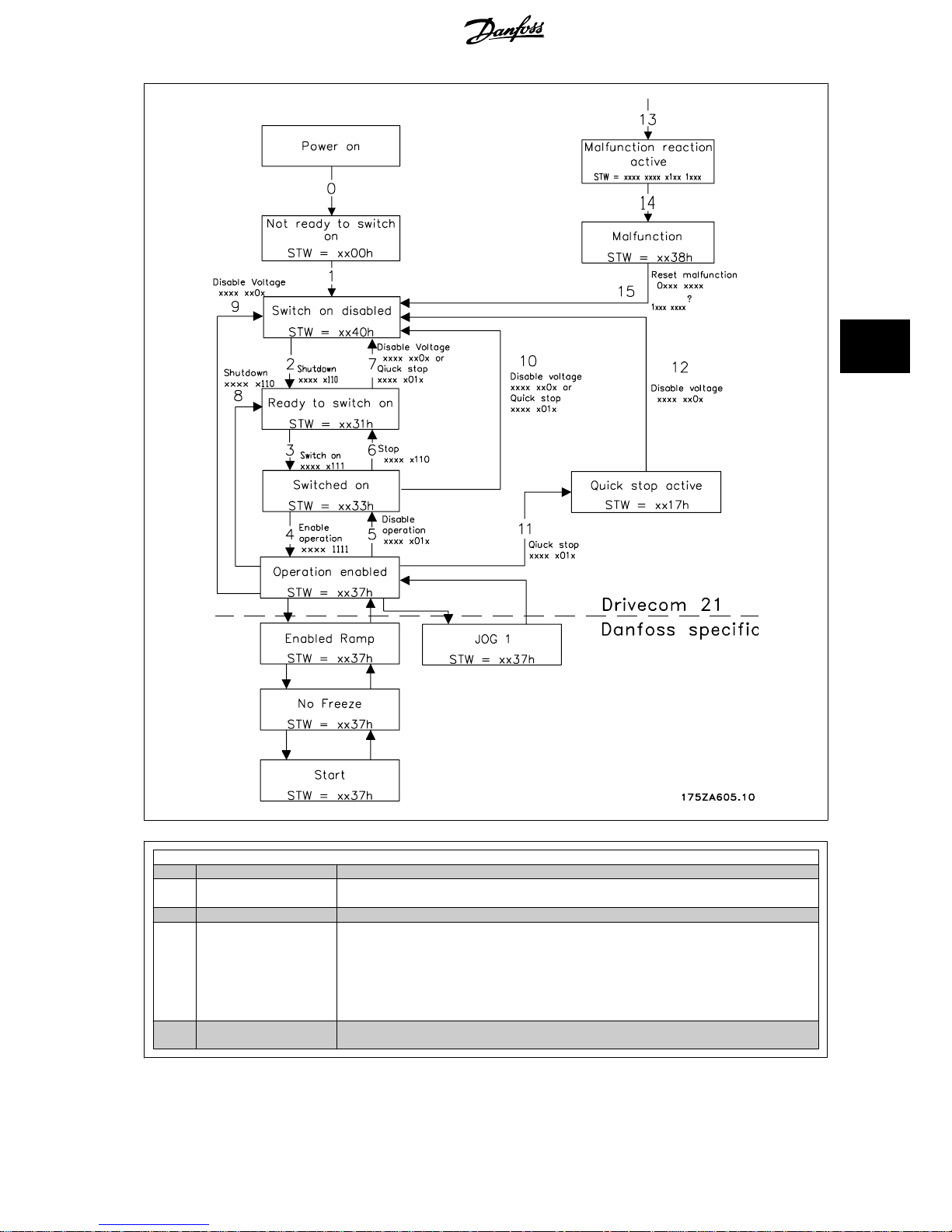
5.2.1. The Drivecom State Machine
The state machine describes the device status and the possible control
sequence of the frequency converter. A status represents a specific in-
ternal and external response. By means of device control commands and/
or internal events, the status can be changed and a control sequence thus
executed. The current status can be read out via the frequency
converter’s status word.
The flow chart to the right and the following explanation may help to
understand the principle: To change from state A to state B, the condition
“Control word bit 1” has to be set to 0. This causes the transition 0 to be
executed. In state B the status word is: xx01H.
FC 300 Interbus Operating Instructions 5. How to Control the FC 300
MG.33.H3.02 - VLT is a registered Danfoss trademark
21
5
Page 22

5.2.2. Description of Transitions
The following describes each transaction that the Drivecom state machine executes for a given command.
0 Input of the state machine NOT READY TO SWITCH ON.
→
Event: - Reset
Action: - Start self-test - Start initialization
1 NOT READY TO SWITCH ON SWITCH ON DISABLED
→
Event: - Error-free self-test - Initialization completed without errors occurring.
Action: - Activate communication and process data monitoring.
2 SWITCH ON DISABLED READY TO SWITCH ON
→
Event: - “Shutdown” command
Condition: - Dependent on the manufacturer-specific requirements (e.g. power section ready)
Action: - None
3 READY TO SWITCH ON SWITCHED ON
→
Event: - “Switch-on” command
Action: - The power section is switched on if it is not already switched on.
4 SWITCHED ON OPERATION ENABLED
→
Event: - “Enable-Operation” command
Action: - Enable drive function
5 OPERATION ENABLED SWITCHED ON
→
Event: - “Disable-Operation” command
Action: - Execute the parameter-definable “Drive- Disable-Function”
6 SWITCHED ON READY TO SWITCH ON
→
Event: - “Shutdown” command
Action: - The power section can be switched off
7 READY TO SWITCH ON SWITCH ON DISABLED
→
Event: - “Quick-Stop” or “Disable-Voltage” command
Action: - None
8 OPERATION ENABLED READY TO SWITCH ON
→
Event: - “Shutdown” commands
Action: - Execute the parameter definable “Drive- Disable-Function”
- The power section can be switched off
9 OPERATION ENABLED SWITCH ON DISABLED
→
Event: - “Disable-Voltage” command
Action: - Disable drive function
- The power section can be switched off
10 SWITCHED ON SWITCH ON DISABLED
→
Event: - “Disable-Voltage” command
or - “Quick-Stop” command
Action: - The power section can be switched off
11 OPERATION ENABLED QUICK STOP ACTIVE
→
Event: - “Quick-Stop” command
Action: - Trigger the parameter-definable “Quick - Stop-Function”
5. How to Control the FC 300 FC 300 Interbus Operating Instructions
22
MG.33.H3.02 - VLT is a registered Danfoss trademark
5
Page 23

12 QUICK STOP ACTIVE SWITCH ON DISABLED→
Event: - Quick stop has been completed or - “Disable-Voltage” command
Action: - Disable drive function
- The power section can be switched off
13 All states MALFUNCTION REACTION ACTIVE
→
Event: - Drive malfunction detected Action: - Trigger malfunction reaction depending on the fault
14 MALFUNCTION REACTION ACTIVE MALFUNCTION
→
Event: - Malfunction reaction concluded
Action: - Disable drive function
- The power section can be switched off
15 MALFUNCTION SWITCH ON DISABLED
→
Event: - “Malfunction-Reset” command
Condition: - Malfunction is no longer present
Action: - Malfunction reset is executed
FC 300 Interbus Operating Instructions 5. How to Control the FC 300
MG.33.H3.02 - VLT is a registered Danfoss trademark
23
5
Page 24

5.3. Drivecom 21 Control Profile
5.3.1. Control Word according to Drivecom 21 Profile
(Par. 8-10 = PROFIdrive profile)
Bit Bit value = 0 Bit value = 1
00 Switch off Switch on
01 Disable voltage Enable voltage
02 Quick stop Run
03 Disable operation Enable operation
04 Disable ramp Enable ramp
05 Freeze Run enable
06 Ramp stop Start
07 No function Reset
08 Reserved
09 Reserved
10 Reserved
11 Jog 1 OFF Jog 1 ON
12 Reserved
13 Setup select (LSB)
14 Setup select (MSB)
15 Forward Reversing
Explanation of the Bits:
Bit 00, Switch OFF/ON:
Bit 00= "0" execute transition 2, 6 or 8.
Bit 00 = "1" execute transition 3.
Bit 01, Disable/Enable Voltage:
Bit 01= "0" execute transition 9, 10 or 12.
Bit 01 = "1" = “Enable Voltage“.
Bit 02, Quick stop/Run:
Bit 02= "0" execute transition 7, 10 or 11.
Bit 02 = "1" = Quick stop not active.
Bit 03, Disable/enable Operation:
Bit 03= "0" execute transition 5.
Bit 03 = "1" = “Enable operation“.
Bit 04, Quick-stop/ramp:
Bit 04= "0" execute transition 7 or 11, Quick stop.
Bit 04 = "1" = Enable ramp.
Bit 05, Freeze output frequency/run enable:
Bit 05 = "0" means that the given output frequency is maintained even
if the reference is changed.
Bit 05 = "1" means that the frequency converter is again able to regulate,
and the given reference is followed.
Bit 06, Ramp stop/start:
Bit 06= "0" The VLT controls the motor down to stop.
Bit 06 = "1" = Start command to the VLT is given.
Bit 07, No function/reset:
Reset of trip.
Bit 07 = "0" means that there is no reset.
Bit 07 = "1" means that a trip is reset.
Bit 08, 09 and 10:
Drivecom reserved.
Bit 11, Jog 1 OFF/ON:
Activation of pre-programmed speed in par. 8-90 Bus JOG 1. JOG 1 is
only possible if Bit 04 = "0", and bit 00 to 03 = "1".
Bit 12:
Danfoss reserved.
Bits 13/14, Selection of Setup:
Bits 13 and 14 are used for choosing among the four menu Setups in
accordance with the following table:
Bit 14 Bit 13 Setup
0 0 1
0 1 2
1 0 3
1 1 4
Bit 15, Forward/reversing:
Bit 15 = "0" leads to no reversing.
Bit 15 = "1" leads to reversing.
Note: In factory setting reversing is set to [digital] in par. 8-54
Reversing
select
.
5. How to Control the FC 300 FC 300 Interbus Operating Instructions
24
MG.33.H3.02 - VLT is a registered Danfoss trademark
5
Page 25
5.3.2. Status Word according to Drivecom 21 Profile
(Par. 8-10 = PROFIdrive profile)
Bit Bit value = 0 Bit value = 1
00 Not ready to switch ON Ready to switch ON
01 Switched OFF Switched ON
02 Operation disabled Operation enabled
03 No malfunction Malfunction
04 Voltage disabled Voltage enabled
05 Quick stop Run
06 Switch on disable Switch on enable
07 No warning Warning
08 Reserved
09 Remote disabled Remote enabled
10 Setpoint not reached Setpoint reached
11 Speed limit not active Speed limit active
12 Reserved
13 Reserved
14 Not running Running
15 Torque limit o.k. Torque limit exceeded
Explanation of the Bits:
Bit 00, Not ready to switch on/Ready to switch on:
Bit 00 = "0" state less than “Ready to switch on”.
Bit 00 = "1" state at least = “Ready to Switch on”.
Bit 01, Switch off/Switch on:
Bit 00 = "0" state less than “Switched on”.
Bit 00 = "1" state at least = “Switched on”.
Bit 02, Operation disable/Operation enable:
Bit 00 = "0" state less than “Operation enable”.
Bit 00 = "1" state at least = “Operation enable”.
Bit 03, No Malfunction/Malfunction:
Bit 03 = "0" means that the connection from Interbus option to is o.k.
Bit 03 = "1" means that the connection between Interbus option and has
been lost, or no is found.
Bit 04, Voltage disable/Voltage enable:
Bit 04 = "0" means that control word bit 01 = "1".
Bit 04 = "1" means that control word bit 01 = "0".
Bit 05, Quick stop/Run:
Bit 05 = "0" means that control word bit 02 = "1".
Bit 05 = "1" means that control word bit 02 = "0".
Bit 06, Start enable/Start disable:
Bit 06 = "0" state is “Switch on disable”.
Bit 06 = "1" state is “Switch on enable”.
Bit 07, No warning/Warning:
Bit 07 = "0" means that there is no warning situation.
Bit 07 = "1" means that a warning has occurred.
Bit 08, Danfoss reserved
Bit 09, Remote disable/Remote enable:
Bit 09 = "0" means that the has been stopped by means of the stop key
on the LCP, or that [Local] has been selected in par. 3-13 Reference site.
Bit 09 = "1" means that it is possible to control the converter via the serial
port.
Bit 10, Setpoint not reached/Setpoint reached:
Bit 10 = "0" means that the actual motor speed is different from the speed
reference set. This can be the case while the speed is ramped up/down
during start/stop.
Bit 10 = "1" means that the present motor speed equals the speed ref-
erence set.
Bit 11, Speed limit not active/speed limit active:
Bit 11 = "0" means that the output frequency is out of the range set in
par. 4-11/4-12 Motor Speed low Limit RPM/Hz or par. 4-13/4-14 Motor
Speed high Limit RPM/Hz.
Bit 11 = "1" means that the output frequency is within the mentioned
range.
Bit 12, Drivecom reserved
Bit 13, Drivecom reserved
Bit 14, Running/Not running:
Bit 14 = "0" means that the motor is not running.
Bit 14 = "1" means that the has a valid start signal or that the output
frequency is greater than 0 Hz.
Bit 15, Torque limit o.k./Torque limit exceeded:
Bit 15 = "0" means the torque limit received via PDC 4 is accepted and
within range.
Bit 15 = "1" means the torque limit received exceeds the limits in par.
4-15 and 4-16.
FC 300 Interbus Operating Instructions 5. How to Control the FC 300
MG.33.H3.02 - VLT is a registered Danfoss trademark
25
5
Page 26

5.4. Danfoss FC Control Profile
5.4.1. Control Word according to FC Profile
(Par. 8-10 = FC profile)
Bit Bit value = 0 Bit value = 1
00 Reference value External selection lsb
01 Reference value External selection msb
02 DC brake Ramp
03 Coasting No coasting
04 Quick stop Ramp
05 Hold output frequency Use ramp
06 Ramp stop Start
07 No function Reset
08 No function Jog
09 Ramp 1 Ramp 2
10 Data invalid Data valid
11 No function Relay 01 active
12 No function Relay 04 active
13 Parameter set-up Selection lsb
14 Parameter set-up Selection msb
15 No function Reverse
Explanation of the Control Bits:
Bits 00/01
Bits 00 and 01 are used to choose between the four reference values,
which are pre-programmed in par. 3-10
Preset Reference
according to
the following table:
Programmed
ref. value
Parameter Bit 01 Bit 00
1 3-10 [0] 0 0
2 3-10 [1] 0 1
3 3-10 [2] 1 0
4 3-10 [3] 1 1
NB!
In par. 8-56
Preset Reference Select
a selection is
made to define how Bit 00/01 gates with the corre-
sponding function on the digital inputs.
Bit 02, DC brake:
Bit 02 = ’0’ leads to DC braking and stop.
Braking current and duration are set in par. 2-01
DC Brake Current
and
2-02
DC Braking Time
.
Bit 02 = ’1’ leads to ramping.
Bit 03, Coasting:
Bit 03 = ’0’ causes the frequency converter to immediately "let go" of the
motor (the output transistors are "shut off"), so that it coasts to a stand-
still.
Bit 03 = ’1’ enables the frequency converter to start the motor if the other
starting conditions have been fulfilled.
NB!
In par. 8-50
Coasting Select
a selection is made to de-
fine how Bit 03 gates with the corresponding function
on a digital input.
Bit 04, Quick stop:
Bit 04 = ’0’ causes a stop, in which the motor speed is ramped down to
stop via par. 3-81
Quick Stop Ramp Time
.
Bit 05, Hold output frequency:
Bit 05 = ’0’ causes the present output frequency (in Hz) to freeze. The
frozen output frequency can then be changed only by means of the digital
inputs (par. 5-10 to 5-15) programmed to
Speed up
and
Speed down
.
NB!
If Freeze output is active, the frequency converter can
only be stopped by the following:
• Bit 03 Coasting stop
• Bit 02 DC braking
• Digital input (par. 5-10 to 5-15) programmed
to
DC braking, Coasting stop
or
Reset
and
Coasting stop
.
Bit 06, Ramp stop/start:
Bit 06 = ’0’ causes a stop, in which the motor speed is ramped down to
stop via the selected
ramp down
parameter.
Bit 06 = ’1’ permits the frequency converter to start the motor, if the other
starting conditions have been fulfilled.
NB!
In par. 8-53
Start Select
a selection is made to define
how Bit 06 Ramp stop/start gates with the correspond-
ing function on a digital input.
Bit 07, Reset:
Bit 07 = ’0’ does not cause a reset.
Bit 07 = ’1’ causes the reset of a trip. Reset is activated on the signal’s
leading edge, i.e. when changing from logic ’0’ to logic ’1’.
5. How to Control the FC 300 FC 300 Interbus Operating Instructions
26
MG.33.H3.02 - VLT is a registered Danfoss trademark
5
Page 27
Bit 08, Jog:
Bit 08 = ’1’ causes the output frequency to be determined by par. 3-19
Jog Speed
.
Bit 09, Selection of ramp 1/2:
Bit 09 = "0" means that ramp 1 is active (par. 3-40 to 3-47).
Bit 09 = "1" means that ramp 2 (par. 3-50 to 3-57) is active.
Bit 10, Data not valid/Data valid:
Is used to tell the frequency converter whether the control word is to be
used or ignored.
Bit 10 = ’0’ causes the control word to be ignored,
Bit 10 = ’1’ causes the control word to be used.
This function is relevant, because the control word is always contained in
the telegram, regardless of which type of telegram is used, i.e. it is pos-
sible to turn off the control word if you do not wish to use it in connection
with updating or reading parameters.
Bit 11, Relay 01:
Bit 11 = "0" Relay not activated.
Bit 11 = "1" Relay 01 activated, provided
Control word bit 11
has been
chosen in par. 5-40
Function Relay
.
Bit 12, Relay 04:
Bit 12 = "0" Relay 04 has not been activated.
Bit 12 = "1" Relay 04 has been activated, provided
Control word bit 12
has been chosen in par. 5-40
Function Relay
.
Bit 13/14, Selection of set-up:
Bits 13 and 14 are used to choose from the four menu set-ups according
to the following table:
Setup Bit 14 Bit 13
1 0 0
2 0 1
3 1 0
4 1 1
The function is only possible when
Multi-Set-ups
is selected in par. 0-10
Active Set-up
.
NB!
In par. 8-55
Set-up Select
a selection is made to define
how Bit 13/14 gates with the corresponding function
on the digital inputs.
Bit 15 Reverse:
Bit 15 = ’0’ causes no reversing.
Bit 15 = ’1’ causes reversing.
Note: In the factory setting reversing is set to
digital
in par. 8-54
Revers-
ing Select
.
Bit 15 causes reversing only when
Ser. communication, Logic or
or
Logic
and
is selected.
FC 300 Interbus Operating Instructions 5. How to Control the FC 300
MG.33.H3.02 - VLT is a registered Danfoss trademark
27
5
Page 28

5.4.2. Status Word according to FC Profile (STW)
(Par. 8-10 = FC profile)
Bit Bit value = 0 Bit value = 1
00 Control not ready Control ready
01 Drive not ready Drive ready
02 Coasting Enable
03 No error Trip
04 No error Error (no trip)
05 Reserved 06 No error Trip lock
07 No warning Warning
08 Speed ≠ reference Speed = reference
09 Local operation Bus control
10 Out of frequency limit Frequency limit ok
11 No operation In operation
12 Drive ok Stopped, auto start
13 Voltage ok Voltage exceeded
14 Torque ok Torque exceeded
15 Timer ok Timer exceeded
Explanation of the Status Bits:
Bit 00, Control not ready/ready:
Bit 00 = ’0’ means that the frequency converter has tripped.
Bit 00 = ’1’ means that the frequency converter controls are ready, but
that the power component is not necessarily receiving any power supply
(in case of external 24 V supply to controls).
Bit 01, Drive ready:
Bit 01 = ’1’. The frequency converter is ready for operation, but there is
an active coasting command via the digital inputs or via serial communi-
cation.
Bit 02, Coasting stop:
Bit 02 = ’0’. The frequency converter has released the motor.
Bit 02 = ’1’. The frequency converter can start the motor when a start
command is given.
Bit 03, No error/trip:
Bit 03 = ’0’ means that the frequency converter is not in fault mode.
Bit 03 = ’1’ means that the frequency converter is tripped, and that a
reset signal is required to re-establish operation.
Bit 04, No error/error (no trip):
Bit 04 = ’0’ means that the frequency converter is not in fault mode.
Bit 04 = “1” means that there is a frequency converter error but no trip.
Bit 05, Not used:
Bit 05 is not used in the status word.
Bit 06, No error / trip lock:
Bit 06 = ’0’ means that the frequency converter is not in fault mode.
Bit 06 = “1” means that the frequency converter is tripped, and locked.
Bit 07, No warning/warning:
Bit 07 = ’0’ means that there are no warnings.
Bit 07 = ’1’ means that a warning has occurred.
Bit 08, Speed≠ reference/speed = reference:
Bit 08 = ’0’ means that the motor is running, but that the present speed
is different from the preset speed reference. For example, this might oc-
cur while the speed is being ramped up/down during start/stop.
Bit 08 = ’1’ means that the present motor present speed matches the
preset speed reference.
Bit 09, Local operation/bus control:
Bit 09 = ’0’ means that [STOP/RESET] is activated on the control unit, or
that
Local control
in par. 3-13
Reference site
is selected.
It is not possible to control the frequency converter via serial communi-
cation.
Bit 09 = ’1’ means that it is possible to control the frequency converter
via the fieldbus/ serial communication.
Bit 10, Out of frequency limit:
Bit 10 = ’0’, if the output frequency has reached the value in par. 4-11
Motor Speed Low Limit
or par. 4-13
Motor Speed High Limit
.
Bit 10 = "1" means that the output frequency is within the defined limits.
Bit 11, No operation/in operation:
Bit 11 = ’0’ means that the motor is not running.
Bit 11 = ’1’ means that the frequency converter has a start signal or that
the output frequency is greater than 0 Hz.
Bit 12, Drive OK/stopped, auto start:
Bit 12 = ’0’ means that there is no temporary over temperature on the
inverter.
Bit 12 = ’1’ means that the inverter has stopped because of over tem-
perature, but that the frequency converter has not tripped and will
resume operation once the over temperature stops.
Bit 13, Voltage OK/limit exceeded:
Bit 13 = ’0’ means that there are no voltage warnings.
Bit 13 = ’1’ means that the DC voltage in the frequency converter’s in-
termediate circuit is too low or too high.
Bit 14, Torque OK/limit exceeded:
Bit 14 = ’0’ means that the motor current is lower than the torque limit
selected in par. 4-18
Current Limit
.
Bit 14 = ’1’ means that the torque limit in par. 4-18
Current Limit
has
been exceeded.
5. How to Control the FC 300 FC 300 Interbus Operating Instructions
28
MG.33.H3.02 - VLT is a registered Danfoss trademark
5
Page 29

Bit 15, Timer OK/limit exceeded:
Bit 15 = ’0’ means that the timers for motor thermal protection and VLT
thermal protection, respectively, have not exceeded 100%.
Bit 15 = ’1’ means that one of the timers has exceeded 100%.
NB!
All bits in the STW is set to ’0’ if the connection be-
tween the Interbus option and the frequency converter
is lost, or an internal communication problem has oc-
curred.
FC 300 Interbus Operating Instructions 5. How to Control the FC 300
MG.33.H3.02 - VLT is a registered Danfoss trademark
29
5
Page 30

5.4.3. Bus Speed Reference Value
The speed reference value is transmitted to the frequency converter in a
relative value in %.
The value is transmitted in the form of a 16-bit word; in integers
(0-32767) the value 16384 (4000 Hex) corresponds to 100%.
Negative figures are formatted by means of 2’s complement.
The Actual Output frequency (MAV) are scaled in the same way as the
bus reference.
The reference and MAV are scaled as follows:
For examples on reference scaling please refer to section:
Troubleshooting
.
5. How to Control the FC 300 FC 300 Interbus Operating Instructions
30
MG.33.H3.02 - VLT is a registered Danfoss trademark
5
Page 31

6. How to Access the FC 300 Parameters
6.1. PCP Communication
For read and write of FC 300 parameters, the Interbus Peripherals Communication Protocol (PCP) channel has to be used.
The Danfoss FC 300 Interbus option supports the following services:
- Initiate: Establish connection between master and the FC 300.
- Abort: Cancel connection between master and FC 300.
- Read: Read FC 300 Parameters.
- Write: Write FC 300 Parameters.
- Get Object description: Both short and long are supported.
- Identify: Identification of the FC 300 to the Master.
The following entries must be made in the Master for PCP communication:
Communication reference 2
Transmit buffer length 246
Receive buffer length 246
Supported service request 80 30 00 hex
Supported service response 00 00 00 hex
All parameters in the FC 300 are mapped to the Danfoss specific objects, starting from object 22000 = 55F0hex.
The first object is 22001 (55F1hex), which corresponds to par. 0-01.
22002 corresponds to par. 0-02 and so on.
This means that all parameters can be accessed by using PCP communication, just by adding 22000D to the FC 300 parameter.
To access FC 300 objects for reading and writing, it is necessary to set up the correct data size and index for the particular parameter.
The option board can provide the complete list of objects to the user by using the GET OD command.
Alternatively the user can set up the command for the object manually.
FC 300 Interbus Operating Instructions 6. How to Access the FC 300 Parameters
MG.33.H3.02 - VLT is a registered Danfoss trademark
31
6
Page 32

7. Parameters FC 300 Interbus Operating Instructions
32
MG.33.H3.02 - VLT is a registered Danfoss trademark
7
Page 33
7. Parameters
8-01 Control Site
The setting in this parameter overrules the settings in par. 8-50 to 8-56.
Option: Function:
[0] * Digital and ctrl. word Select
Digital and ctrl. word
[0] for control using both digital input and control word.
[1] Digital only Select
Digital only
[1] for control using digital inputs only.
[2] Control word only Select
Control word only
[2] for control using control word only
NB!
Must be set to [2]
Control word only
for operation with the Interbus option.
8-02 Control Word Source
Select the source of the control word: one of two serial interfaces or four installed options. During initial power-up, the frequency converter automatically
sets this parameter to
Option A
[3] if it detects a valid fieldbus option installed in slot A. If the option is removed, the frequency converter detects a
cha nge in t he c onf iguration, s ets par . 8-02
Control Word Source
back to default setting
FC RS485
, and the frequency converter then trips. If an option
is installed after initial power-up, the setting of par. 8-02
Control Word Source
will not change but the frequency converter will trip and display: Alarm
67
Option Changed
.
This parameter cannot be adjusted while the motor is running.
Option: Function:
[0] None
[1] FC RS485
[2] FC USB
[3] * Option A
[4] Option B
[5] Option C0
[6] Option C1
[30] External Can
8-03 Control Word Timeout Time
Range: Function:
1.0 s* [0.1 - 18000.0 s] Enter the maximum time expected to pass between the reception of two consecutive telegrams. If
this time is exceeded, it indicates that the serial communication has stopped. The function selected
in par. 8-04 Control
Word Timeout Function
will then be carried out. The time-out counter is trig-
gered by a valid control word.
8-04 Control Word Timeout Function
Select the time-out function. The time-out function activates when the control word fails to be updated within the time period specified in par. 8-03
Control Word Time-out Time
Option: Function:
[0] * Off Resume control via serial bus (Fieldbus or standard) using the most recent control word.
[1] Freeze output Freeze output frequency until communication resumes.
[2] Stop Stop with auto restart when communication resumes.
[3] Jogging Run the motor at JOG frequency until communication resumes.
[4] Max. speed Run the motor at maximum frequency until communication resumes.
[5] Stop and trip Stop the motor, then reset the frequency converter in order to restart: via the fieldbus, via the reset
button on the LCP or via a digital input.
FC 300 Interbus Operating Instructions 7. Parameters
MG.33.H3.02 - VLT is a registered Danfoss trademark
33
7
Page 34

NB!
Must be set to [5]
Stop and trip
for operation with the Interbus option.
[7] Select set-up 1 This option changes the set-up upon reestablishment of communication following a control word
time-out. If communication resumes causing the time-out situation to disappear, par. 8-05
End-of-
time-out Function
defines whether to resume the set-up used before the time-out or to retain the
set-up endorsed by the time-out function. Note the following configuration required in order to
change the set-up after a time-out: Set Par. 0-10
Active set-up to Multi set-up
[9], and select the
relevant link in par. 0-12
This Set-up Linked To
.
[8] Select set-up 2 This option changes the set-up upon reestablishment of communication following a control word
time-out. If communication resumes causing the time-out situation to disappear, par. 8-05
End-of-
time-out Function
defines whether to resume the set-up used before the time-out or to retain the
set-up endorsed by the time-out function. Note the following configuration required in order to
change the set-up after a time-out: Set Par. 0-10
Active set-up to Multi set-up
[9], and select the
relevant link in par. 0-12
This Set-up Linked To
.
[9] Select set-up 3 This option changes the set-up upon reestablishment of communication following a control word
time-out. If communication resumes causing the time-out situation to disappear, par. 8-05
End-of-
time-out Function
defines whether to resume the set-up used before the time-out or to retain the
set-up endorsed by the time-out function. Note the following configuration required in order to
change the set-up after a time-out: Set Par. 0-10
Active set-up to Multi set-up
[9], and select the
relevant link in par. 0-12
This Set-up Linked To
.
[10] Select set-up 4 This option changes the set-up upon reestablishment of communication following a control word
time-out. If communication resumes causing the time-out situation to disappear, par. 8-05
End-of-
time-out Function
defines whether to resume the set-up used before the time-out or to retain the
set-up endorsed by the time-out function. Note the following configuration required in order to
change the set-up after a time-out: Set Par. 0-10
Active set-up to Multi set-up
[9], and select the
relevant link in par. 0-12
This Set-up Linked To
.
8-05 End-of-Timeout Function
Option: Function:
Select the action after receiving a valid control word following a time-out. This parameter is active
only when par. 8-04 Control
Timeout Function
is set to [Set-up 1-4].
[0] Hold set-up Retains the set-up selected in par. 8-04 Control
Timeout Function
and displays a warning, until par.
8-06 Reset
Control Timeout
toggles. Then the frequency converter resumes its original set-up.
[1] * Resume set-up Resumes the set-up active prior to the time-out.
8-06 Reset Control Word Timeout
This parameter is active only when
Hold set-up
[0] has been selected in par. 8-05
End-of-Timeout Function
.
Option: Function:
[0] * Do not reset Retains the set-up specified in par. 8-04 Control
Word Timeout Function
, following a control word
time-out.
[1] Do reset Returns the frequency converter to the original set-up following a control word time-out. The fre-
quency converter performs the reset and then immediately reverts to the
Do not reset
[0] setting
8-07 Diagnosis Trigger
Option: Function:
This parameter has no function for LonWorks.
[0] * Disable
[1] Trigger on alarms
[2] Trigger alarm/warn.
7. Parameters FC 300 Interbus Operating Instructions
34
MG.33.H3.02 - VLT is a registered Danfoss trademark
7
Page 35
8-10 Control Word Profile
Select the interpretation of the control and status words corresponding to the installed fieldbus. Only the selections valid for the fieldbus installed in
slot A will be visible in the LCP display.
Option: Function:
[0] * FC profile For guidelines in selection of
FC profile
[0] please refer to the
Serial communication via RS 485
Interface
section in the
How to Programme
chapter.
[1] PROFIdrive profile For guidelines in selection of
PROFIdrive profile
[1] please refer to the
Serial communication via RS
485 Interface
section in the
How to Programme
chapter.
For additional guidelines in the selection of
PROFIdrive profile
[1], please refer to the Operating
Instructions for the installed fieldbus.
NB!
Setting par. 8-10 to [1]
PROFIdrive profile
enables the Drivecom Profile on the
Interbus option, i.e. Control word and Status word are interpreted as Drivecom.
Setting par. 8-10 to [0]
FC Profile
enables the FC profile on the frequency con-
verter.
[5] ODVA For additional guidelines in the selection of
ODVA
[5], please refer to the Operating Instructions for
the installed fieldbus.
[7] CANopen DSP 402 For additional guidelines in the selection of
CANopen DSP 402
[7], please refer to the Operating
Instructions for the installed fieldbus.
8-32 FC Port Baud Rate
Baud rate selection for the FC (standard) port.
Option: Function:
[0] 2400 Baud
[1] 4800 Baud
[2] * 9600 Baud
[3] 19200 Baud
[4] 38400 Baud
NB!
Must be set to 38400 Baud [4] for operation with the Interbus option.
[7] 115200 Baud
8-40 Telegram Selection
This parameter enables to select the telegram type used on Interbus.
For more information on telegram types, please refer to chapter:
How to Control the FC 300
.
Option: Function:
[1] Standard telegram 1
[200] Custom telegram 1
8-50 Coasting Select
Option: Function:
Select control of the coasting function via the terminals (digital input) and/or via the bus.
[0] Digital input
[1] Bus
[2] Logic AND
[3] * Logic OR
FC 300 Interbus Operating Instructions 7. Parameters
MG.33.H3.02 - VLT is a registered Danfoss trademark
35
7
Page 36

NB!
This parameter is active only when par. 8-01 Control
Site
is set to [0]
Digital and control word
.
8-51 Quick Stop Select
Option: Function:
[0] Digital input
[1] Bus
[2] Logic AND
[3] * Logic OR Select control of the Quick Stop function via the terminals (digital input) and/or via the bus.
NB!
This para meter is acti ve only when p ar. 8-01 Cont rol
Site
is set to [0]
Digital and
control word
.
8-52 DC Brake Select
Option: Function:
Select control of the DC brake via the terminals (digital input) and/or via the fieldbus.
[0] Digital input
[1] Bus
[2] Logic AND
[3] * Logic OR
NB!
This parameter is active only when par. 8-01 Control
Site
is set to [0]
Digital and control word
.
8-53 Start Select
Option: Function:
Select control of the frequency converter start function via the terminals (digital input) and/or via
the fieldbus.
[0] Digital input Activates Start command via a digital input.
[1] Bus Activates Start command via the serial communication port or fieldbus option.
[2] Logic AND Activates Start command via the fieldbus/serial communication port, AND additionally via one of the
digital inputs.
[3] * Logic OR Activates Start command via the fieldbus/serial communication port OR via one of the digital inputs.
NB!
This parameter is active only when par. 8-01 Control
Site
is set to [0]
Digital and control word
.
8-54 Reversing Select
Option: Function:
[0] Digital input Select control of the frequency converter reverse function via the terminals (digital input) and/or
via the fieldbus.
[1] Bus Activates the Reverse command via the serial communication port or fieldbus option.
7. Parameters FC 300 Interbus Operating Instructions
36
MG.33.H3.02 - VLT is a registered Danfoss trademark
7
Page 37
[2] Logic AND Activates the Reverse command via the fieldbus/serial communication port, AND additionally via
one of the digital inputs.
[3] * Logic OR Activates the Reverse command via the fieldbus/serial communication port OR via one of the digital
inputs.
NB!
This parameter is only active when par. 8-01 Control
Site
is set to [0]
Digital and control word
.
8-55 Set-up Select
Option: Function:
Select control of the frequency converter set-up selection via the terminals (digital input) and/or via
the fieldbus.
[0] Digital input Activates the set-up selection via a digital input.
[1] Bus Activates the set-up selection via the serial communication port or fieldbus option.
[2] Logic AND Activates the set-up selection via the fieldbus/serial communication port, AND additionally via one
of the digital inputs.
[3] * Logic OR Activate the set-up selection via the fieldbus/serial communication port OR via one of the digital
inputs.
NB!
This parameter is active only when par. 8-01 Control
Site
is set to [0]
Digital and control word
.
8-56 Preset Reference Select
Option: Function:
Select control of the frequency converter Preset Reference selection via the terminals (digital input)
and/or via the fieldbus.
[0] Digital input Activates Preset Reference selection via a digital input.
[1] Bus Activates Preset Reference selection via the serial communication port or fieldbus option.
[2] Logic AND Activates Preset Reference selection via the fieldbus/serial communication port, AND additionally
via one of the digital inputs.
[3] * Logic OR Activates the Preset Reference selection via the fieldbus/serial communication port OR via one of
the digital inputs.
NB!
This parameter is active only when par. 8-01 Control
Site
is set to [0]
Digital and control word
.
8-90 Bus Jog 1 Speed
Range: Function:
100 RPM* [0 - par. 4-13 RPM] Enter the jog speed. This is a fixed jog speed activated via the serial port or fieldbus option.
8-90 Bus Jog 1 Speed
Range: Function:
100 RPM* [0 - par. 4-13 RPM] Enter the jog speed. This is a fixed jog speed activated via the serial port or fieldbus option.
FC 300 Interbus Operating Instructions 7. Parameters
MG.33.H3.02 - VLT is a registered Danfoss trademark
37
7
Page 38
8-91 Bus Jog 2 Speed
Range: Function:
200 RPM* [0 - par. 4-13 RPM] Enter the jog speed. This is a fixed jog speed activated via the serial port or fieldbus option.
8-91 Bus Jog 2 Speed
Range: Function:
200 RPM* [0 - par. 4-13 RPM] Enter the jog speed. This is a fixed jog speed activated via the serial port or fieldbus option.
Par.
No. #
Parameter description Default value 4-set-up Change
during
opera-
tion
Conver-
sion in-
dex
Type
8-0* General Settings
8-01 Control Site [0] Digital and ctrl.word All set-ups TRUE - Uint8
8-02 Control Word Source null All set-ups TRUE - Uint8
8-03 Control Word Timeout Time 1.0 s 1 set-up TRUE -1 Uint32
8-04 Control Word Timeout Function [0] Off 1 set-up TRUE - Uint8
8-05 End-of-Timeout Function [1] Resume set-up 1 set-up TRUE - Uint8
8-06 Reset Control Word Timeout [0] Do not reset All set-ups TRUE - Uint8
8-07
Diagnosis Trigger [0] Disable 2 set-ups TRUE - Uint8
8-1* Ctrl. Word Settings
8-10 Control Word Profile [0] FC profile All set-ups TRUE - Uint8
8-13 Configurable Status Word STW [1] Profile Default All set-ups TRUE - Uint8
8-3* FC Port Settings
8-30 Protocol [0] FC 1 set-up TRUE - Uint8
8-31 Address 1 N/A 1 set-up TRUE 0 Uint8
8-32 FC Port Baud Rate [2] 9600 Baud 1 set-up TRUE - Uint8
8-35 Minimum Response Delay 10 ms 1 set-up TRUE -3 Uint16
8-36 Max Response Delay 5000 ms 1 set-up TRUE -3 Uint16
8-37
Max Inter-Char Delay 25 ms 1 set-up TRUE -3 Uint16
8-4* FC MC protocol set
8-40 Telegram selection [1] Standard telegram 1 2 set-ups TRUE - Uint8
8-5* Digital/Bus
8-50 Coasting Select [3] Logic OR All set-ups TRUE - Uint8
8-51 Quick Stop Select [3] Logic OR All set-ups TRUE - Uint8
8-52 DC Brake Select [3] Logic OR All set-ups TRUE - Uint8
8-53 Start Select [3] Logic OR All set-ups TRUE - Uint8
8-54 Reversing Select [3] Logic OR All set-ups TRUE - Uint8
8-55 Set-up Select [3] Logic OR All set-ups TRUE - Uint8
8-56
Preset Reference Select [3] Logic OR All set-ups TRUE - Uint8
8-9* Bus Jog
8-90 Bus Jog 1 Speed 100 RPM All set-ups TRUE 67 Uint16
8-91 Bus Jog 2 Speed 200 RPM All set-ups TRUE 67 Uint16
7. Parameters FC 300 Interbus Operating Instructions
38
MG.33.H3.02 - VLT is a registered Danfoss trademark
7
Page 39
7.3. Data Types Supported by FC 300
7.3.1. Object and Data Types Supported by FC 300
Data types supported by FC 300
Data type Description
3 Integer 16
4 Integer 32
5 Unsigned 8
6 Unsigned 16
7 Unsigned 32
9 Visible string
10 Byte string
33 Standardized value (16 bit)
35 Bit sequence
41 Byte
42 Word
7.3.2. Conversion Index
This number refers to a conversion figure used when writing or reading
to parameters.
Conversion index Conversion factor
100 1
67 1/60
6 1000000
5 100000
4 10000
3 1000
2 100
1 10
0 1
-1 0.1
-2 0.01
-3 0.001
-4 0.0001
-5 0.00001
-6 0.000001
FC 300 Interbus Operating Instructions 7. Parameters
MG.33.H3.02 - VLT is a registered Danfoss trademark
39
7
Page 40

8. Troubleshooting FC 300 Interbus Operating Instructions
40
MG.33.H3.02 - VLT is a registered Danfoss trademark
8
Page 41
8. Troubleshooting
Alarm word and warning word are shown on the display in Hex format.
If there is more than one warning or alarm, a sum of all warnings or
alarms will be shown. Warning word and alarm word can be displayed in
par. 16-90 and 16-92.
FC 300
Bit (Hex) Unit diag-
nose bit
Alarm word (Par. 16-90) Alarm no.
00000001 48 Brake check 28
00000002 49 Power card over tem-
perature
29
00000004 50 Earth fault 14
00000008 51 Control card over tem-
perature
65
00000010 52 Control word timeout 18
00000020 53 Over current 13
00000040 54 Torque limit 12
00000080 55 Motor thermistor over
temp.
11
00000100 40 Motor ETR over temper-
ature
10
00000200 41 Inverter overloaded 9
00000400 42 DC link under voltage 8
00000800 43 DC link over voltage 7
00001000 44 Short circuit 16
00002000 45 Inrush fault 33
00004000 46 Mains phase loss 4
00008000 47 AMA not OK 50
00010000 32 Live zero error 2
00020000 33 Internal fault 38
00040000 34 Brake resistor power
limit
26
00080000 35 Motor phase U is missing 30
00100000 36 Motor phase V is missing 31
00200000 37 Motor phase W is miss-
ing
32
00400000 38 Fieldbus comm. fault 34
00800000 39 24 V supply fault 47
01000000 24 Mains failure 36
02000000 25 1.8 V supply fault 48
04000000 26 Brake resistor short cir-
cuit
25
08000000 27 Brake chopper fault 27
10000000 28 Option change 67
20000000 29 Drive initialisation 80
40000000 30 Safe stop 68
80000000 31 Mechanical brake low 63
FC 300 Interbus Operating Instructions 8. Troubleshooting
MG.33.H3.02 - VLT is a registered Danfoss trademark
41
8
Page 42

FC 300
Bit (Hex) Unit diag-
nose bit
Warning word (Par.
16-92)
Alarm no.
00000001 112 Brake check 28
00000002 113 Power card over temper-
ature
29
00000004 114 Earth fault 14
00000008 115 Control card over tem-
perature
65
00000010 116 Control word timeout 18
00000020 117 Over current 13
00000040 118 Torque limit 12
00000080 119 Motor thermistor over
temp.
11
00000100 104 Motor ETR over temper-
ature
10
00000200 105 Inverter overloaded 9
00000400 106 DC link under voltage 8
00000800 107 DC link over voltage 7
00001000 108 DC link voltage low 6
00002000 109 DC link voltage high 5
00004000 110 Mains phase loss 4
00008000 111 No motor 3
00010000 96 Live zero error 2
00020000 97 10 V low 1
00040000 98 Brake resistor power
limit
26
00080000 99 Brake resistor short cir-
cuit
25
00100000 100 Brake chopper fault 27
00200000 101 Speed limit 49
00400000 102 Fieldbus comm. fault 34
00800000 103 24 V supply fault 47
01000000 88 Mains failure 36
02000000 89 Current limit 59
04000000 90 Low temperature 66
08000000 91 Voltage limit 64
10000000 92 Encoder loss 61
20000000 93 Output frequency limit 62
40000000 94 Unused 80000000 95 Warning word 2 (ext.
stat. word)
-
FC 300
Bit (Hex) Comm. option STW (Par. 16-94)
00000001 Ramping
00000002 AMA tuning
00000004 Start CW/CCW
00000008 Slow down
00000010 Catch up
00000020 Feedback high
00000040 Feedback low
00000080 Output current high
00000100 Output current low
00000200 Output frequency high
00000400 Output frequency low
00000800 Brake check OK
00001000 Braking max.
00002000 Braking
00004000 Out of speed range
00008000 OVC active
00010000 AC brake
00020000 KTY warm
00040000 Fans warm
00080000 Unused
00100000 Unused
00200000 Unused
00400000 Unused
00800000 Unused
01000000 Unused
02000000 Unused
04000000 Unused
08000000 Unused
10000000 Unused
20000000 Unused
40000000 Unused
80000000 Unused
8.1.1. Warning and Alarm Messages
There is a clear distinction between alarms and warnings. When there is an alarm, the frequency converter will enter a fault condition. After the cause
for the alarm has been cleared, the master will have to acknowledge the alarm message before the frequency converter can start operating again. A
warning, on the other hand, may come when a warning condition appears, then disappear when conditions return to normal, without interfering with the
process.
Warnings
Warnings within the frequency converter are represented by a single bit within a warning word. A warning word is always an active parameter. Bit status
FALSE [0] means no warning, while bit status TRUE [1] means warning. Any bit change in the warning word will be notified by a change of bit 7 in the
status word.
Alarms
Following an alarm message the frequency converter will enter Fault condition. Only after the fault has been alleviated and the master has acknowledged
the alarm message by setting bit 7 in the control word, will the frequency converter resume operation. Alarms within the frequency converter are
represented by a single bit within an alarm word. An alarm word is always an action parameter. Bit status FALSE [0] means no fault, while bit status
TRUE [1] means fault.
8. Troubleshooting FC 300 Interbus Operating Instructions
42
MG.33.H3.02 - VLT is a registered Danfoss trademark
8
Page 43

Example 1:
Par. 3-00 = “-Max - +Max”
Par. 3-03 “Max reference” = 1500 RPM
Reference send = 1500hex (5376 dec)
The output can be calculated as:
Example 2:
Par. 3-00 = “Min - Max”
Par. 3-02 “Min reference” = 100 RPM
Par. 3-03 “Max reference” = 1500 RPM
Reference send = 1500hex (5376 dec)
The output can be calculated as:
8.2.1. LED Behaviour Stopped Interbus Comm.
In case of stopped Interbus communication, a particular behaviour of the “FC bus” –LED can be observed. The behaviour and conditions are as follows:
• Interbus communication is stopped by the Master
• The Interbus option is powered-up while the frequency converter is powered off
• The “FC bus” LED is flashing, indicating baud-rate search
• The frequency converter is powered-up
• The “FC bus” LED turns off, indicating baud-rate found and no FC-bus communication.
NB!
This might be interpreted as failing FC-bus communication, but in fact, the FC-bus comm. is inactive due to the stopped Interbus comm.
This is not a failure.
FC 300 Interbus Operating Instructions 8. Troubleshooting
MG.33.H3.02 - VLT is a registered Danfoss trademark
43
8
Page 44

Index
A
Abbreviations 6
Alarm 41
Alarm Word 41
Assumptions 5
B
Bus Jog 2 Speed 38
C
Cable Length 7
Cabling 7
Cmd 13
Configuration 33
Conversion Index 39
D
Data Types 39
Drivecom 21 Control Profile 24
Drivecom Profile 11
E
Emc Precautions 8
G
Grounding 9
H
Hardware 5
I
Incoming Bus 7
Installation 8
L
Leds 10
O
Outgoing Bus 7
Overview 5
P
Parameters 11
Parameters 33, 0
Pcp Communication 31
Process Data 17
Q
Quick Stop Select 36
R
Reset Control Word Timeout 34
S
Safety 4
State Machine 21
Index FC 300 Interbus Operating Instructions
44
MG.33.H3.02 - VLT is a registered Danfoss trademark
Page 45

T
Telegram Selection 35
Torque 19
W
Warning Word 41
FC 300 Interbus Operating Instructions Index
MG.33.H3.02 - VLT is a registered Danfoss trademark
45
 Loading...