

Fact Sheet
VLT® AutomationDrive FC 300
Ambient temperature and derating charts
Products
VLT® AutomationDrive FC 301/302 0.25 kW to 37 kW @ 200 – 240 V AC
VLT® AutomationDrive FC 301/302 0.37 kW to 75 kW @ 380-480/500 V AC
VLT® AutomationDrive FC 301/302 1.1 kW to 75 kW @ 525-690 V AC
VLT® AutomationDrive FC 302 90 kW to 500 kW @ 380-500 V AC
VLT® AutomationDrive FC 302 55 kW to 710 kW @ 525-690 V AC
Ambient temperature – general terms
Designed for variable speed control of
all induction motors and permanent
magnet motors, on any industrial
machine or production line, a VLT®
AutomationDrive FC 300 helps its
owner save energy, increase flexibility,
and optimize processes.
98%
energy efficiency
with flexible robust
operation in a wide
temperature range
n The definition of ambient and
cooling temperature is according to
EN50178, and IEC721-3-3 class 3K3.
n The drive can operate at elevated
ambient temperatures up to +55 °C,
however, the rated current must be
de-rated (please refer to the
derating chart below).
n Do not operate in environments
where the ambient temperature
exceeds 55 °C (131 °F). If the
temperature exceeds ambient
temperature limits, extra air
conditioning of the cabinet or
installation site is required.
Ambient temperature for operation and derating
n All products listed are able to work
at the below given ambient
temperature without any condition
/influence on the fulfillment of
specifications”
n Ambient temperature:
-10 °C to +45 °C
n Ambient temperature:
+45 °C to 55 °C with derating
(refer derating table)
n The drive can operate at
temperatures down to -10 °C (14 °F).
However, proper operation at rated
load is only guaranteed at 0 °C
(32 °F) or higher.
n Temperature range during storage /
transport is -25 to 65/70 °C
(-13 °F- 149/158 °F).
n Avoiding extreme ambient
temperatures prolongs the life of
the equipment and maximizes
overall system reliability.
n As a rule of thumb, the lifetime of
electronic components decreases
by 50% for every 10 °C when
operated above its design
temperature.
n All products listed are able to work
at ambient temperatures up to
50 °C without derating if certain
conditions are met/followed:.
n Applicable for EEF2 Class motors
n Reduce Switching frequency
(refer derating chart)
n Change switching mode to
“60 AVM” from “SFAVM”
drives.danfoss.com
Derating table for different power sizes and switching mode
2
4 6 8 10 12 14 16
0
2
4 6 8 10 12 14 16
e30ba402.10
0
I
(%)
2
4 6 8 10 12 14 16
0
I
(%)
e30ba401.11
n Derate the output current at high
temperatures. This calculation takes
place after the calculations for
derating the switching frequency.
n The result is an attempt to lower the
temperatures by first lowering the
switching frequency, and then
lowering the output current.
n Current derating only takes place if
the user has programmed the unit
to derate in overtemperature
situations. If the user has selected a
trip function for overtemperature
situations, the current derate factor
is not lowered.
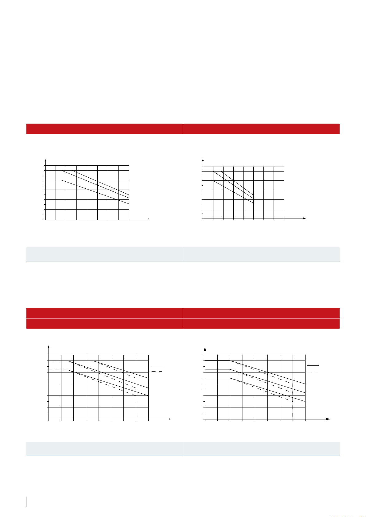
Derating for Ambient Temperature – Enclosure Size A (up to 7.5 kW @ 380-480/500 V)
60 ° AVM - Pulse width modulation SFAVM - Stator frequency induction vector modulation
I
110%
100%
80%
60%
40%
20%
(%)
out
e30ba393.10
A1-A3 45°C, A5 40°C
A1-A3 50°C, A5 45°C
A1-A3 55°C, A5 50°C
0
2
0
4 6 8 10 12 14 16
fsw (kHz)
110%
100%
80%
60%
40%
20%
I
(%)
out
A1-A3 45°C, A4-A5 40°C
A1-A3 50°C, A4-A5 45°C
A1-A3 55°C, A4-A5 50°C
0
e30bd639.10
fsw (kHz)
Illustration 62: Derating of I
Enclosure Size A, using 60° AVM
for Different T
out
AMB,MAX
for
Illustration 63: Derating of I
Enclosure Size A, using SFAVM
out
for Different T
AMB,MAX
for
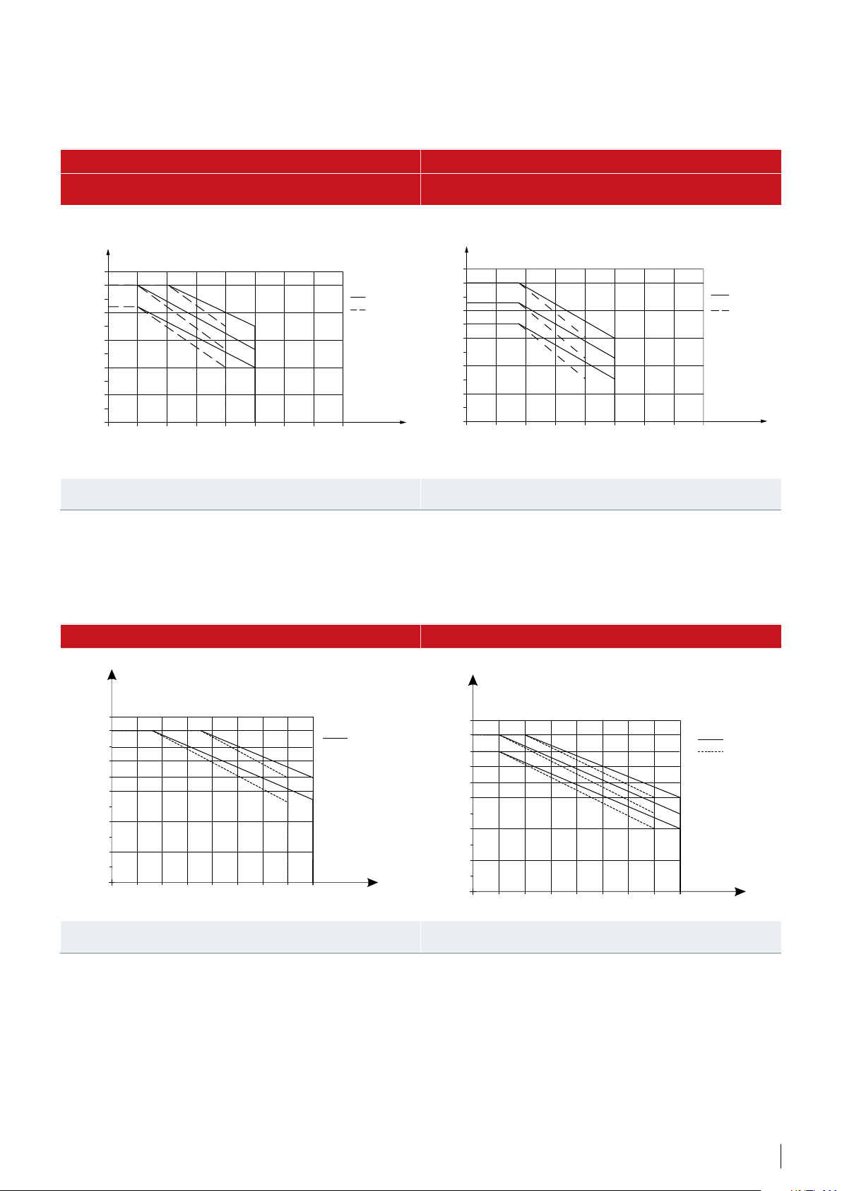
Derating for Ambient Temperature – Enclosure Size B (up to 30 kW (IP20) and 22 kW (IP21/55 @ 380-480/500 V)
B1 & B2 – 60° AVM – High Overload B1 & B2 – 60° AVM - Normal Overload
60° AVM - Pulse width modulation, high overload (160%) 60° AVM - Pulse width modulation, normal overload (110%)
80%
60%
40%
20%
out
NO
45°C
50°C
55°C
f
0
sw
110%
100%
80%
60%
40%
20%
out
HO
B1
B2
45°C
50°C
55°C
f
(kHz)
0
sw
110%
100%
B1
B2
(kHz)
Illustration 66: Derating of I
Enclosure Sizes B1 and B2, using 60° AVM
for Different T
out
2 Danfoss Drives · DKDD.PFF.304.A1.02
AMB,MAX
for
Illustration 67: Derating of I
Enclosure Sizes B1 and B2, using 60° AVM
for Different T
out
AMB,MAX
for
B1 & B2 – SFAVM – High Overload B1 & B2 – SFAVM – Normal Overload
SFAVM - Stator frequency induction vector modulation,
high overload (160%)
(%)
I
out
80%
60%
40%
20%
HO
0
2
0
4 6 8 10 12 14 16
110%
100%
45°C
50°C
55°C
f
sw
B1
B2
(kHz)
SFAVM - Stator frequency induction vector modulation,
normal overload (110%)
I
(%)
out
NO
110%
100%
e30ba404.10
80%
60%
40%
20%
0
2
0
4 6 8 10 12 14 16
45°C
50°C
55°C
f
sw
B1
B2
(kHz)
e30ba403.11
Illustration 70: Derating of I
Enclosure Sizes B1 and B2, using SFAVM
for Different T
out
AMB,MAX
for
Illustration 71: Derating of I
Enclosure Sizes B1 and B2, using SFAVM
for Different T
out
B3 & B4 – 60° AVM- High Overload B3 & B4 – 60° AVM- Normal Overload
(%)
l
110%
100%
90%
80%
60%
40%
20%
out
HO
110%
e30bb830.10
B3 & B4
o
45 C
o
50 C
f
sw
0
0
2 4
6 8
10
12 14
(kHz)
16
100%
90%
80%
60%
40%
20%
(%)
l
out
NO
0
0
2 4
6 8
10
AMB,MAX
12 14
for
16
45 C
50 C
55 C
f
sw
e30bb828.10
B3
B4
o
o
o
(kHz)
Illustration 68: Derating of I
Enclosure Sizes B3 and B4, using 60° AVM
for Different T
out
AMB,MAX
for
Illustration 69: Derating of I
Enclosure Sizes B3 and B4, using 60° AVM
for Different T
out
AMB,MAX
for
3Danfoss Drives · DKDD.PFF.304.A1.02

B3 & B4 – SFAVM – High Overload B3 & B4 – SFAVM – Normal Overload
(%)
l
110%
100%
90%
80%
60%
40%
l
HO
(%)
out
e30bb834.10
B3
B4
o
45 C
o
50 C
110%
100%
90%
80%
60%
40%
out
NO
45 C
50 C
e30bb832.10
B3
B4
o
o
20%
0
0
2 4
Illustration 72: Derating of I
Enclosure Sizes B3 and B4, using SFAVM
6 8
out
10
12 14
for Different T
16
AMB,MAX
f
sw
(kHz)
for
20%
0
0
2 4
Illustration 73: Derating of I
Enclosure Sizes B3 and B4, using SFAVM
6 8
for Different T
out
10
12 14
AMB,MAX
16
for
f
sw
Derating for Ambient Temperature – Enclosure Size C (upto 75 kW 380/500 V)
C1 & C2 – 60° AVM – High Overload C1 & C2 – 60° AVM – Normal Overload
60° AVM - Pulse width modulation, high overload (160%) 60° AVM - Pulse width modulation, normal overload (110%)
(%)
I
110%
100%
80%
60%
40%
20%
out
HO
C1 & C2
e30ba398.10
45°C
50°C
55°C
(kHz)
f
0
2
0
4 6 8 10 12 14 16
sw
110%
100%
80%
60%
40%
20%
I
(%)
out
NO
0
0
2
4 6 8 10 12 14 16
(kHz)
45°C
50°C
55°C
f
sw
C1 & C2
(kHz)
e30ba397.10
Illustration 80: Derating of I
Enclosure Sizes C1 and C2, using 60° AVM
for Different T
out
4 Danfoss Drives · DKDD.PFF.304.A1.02
AMB,MAX
for
Illustration 81: Derating of I
Enclosure Sizes C1 and C2, using 60° AVM
for Different T
out
AMB,MAX
for

C1 & C2 – SFAVM – High Overload C1 & C2 – SFAVM – Normal Overload
SFAVM - Stator frequency induction vector modulation,
high overload (160%)
(%)
I
out
HO
110%
100%
80%
60%
40%
20%
0
2
0
4 6 8 10 12 14 16
45°C
50°C
55°C
f
sw
C1 & C2
(kHz)
SFAVM - Stator frequency induction vector modulation,
normal overload (110%)
(%)
I
out
NO
110%
100%
e30ba400.10
80%
60%
40%
20%
0
0
2
4 6 8 10 12 14 16
45°C
50°C
55°C
f
sw
C1 & C2
(kHz)
e30ba399.10
Illustration 84: Derating of I
Enclosure Sizes C1 and C2, using SFAVM
for Different T
out
AMB,MAX
for
Illustration 85: Derating of I
Enclosure Sizes C1 and C2, using SFAVM
for Different T
out
C3 & C4 – 60° AVM – High Overload C3 & C4 – 60° AVM – Normal Overload
110%
100%
90%
80%
60%
40%
20%
l
HO
out
(%)
2 4
6 8
110%
e30bb831.10
C3 & C4
o
45 C
o
50 C
f
sw
(kHz)
10
12 14
16
100%
90%
80%
60%
40%
20%
(%)
l
out
NO
0
0
2 4
6 8
10
o
45 C
o
50 C
o
55 C
12 14
AMB,MAX
for
C3 & C4
f
sw
(kHz)
16
e30bb829.10
Illustration 82: Derating of I
Enclosure Sizes C3 and C4, using 60° AVM
for Different T
out
AMB,MAX
for
Illustration 83: Derating of I
Enclosure Sizes C3 and C4, using 60° AVM
for Different T
out
AMB,MAX
for
5Danfoss Drives · DKDD.PFF.304.A1.02

C3 & C4 – SFAVM – High Overload C3 & C4 – SFAVM – Normal Overload
e30bb835.10
Iout [%]
fsw [kHz]
(%)
l
out
HO
110%
100%
90%
80%
o
60%
40%
20%
0
0
2 4
Illustration 86: Derating of I
Enclosure Sizes C3 and C4, using SFAVM
45 C
50 C
6 8
for Different T
out
o
10
12 14
AMB,MAX
16
for
110%
100%
C3 & C4
f
sw
(kHz)
90%
80%
60%
40%
20%
Illustration 87: Derating of I
Enclosure Sizes C3 and C4, using SFAVM
(%)
l
out
NO
0
0
2 4
Derating for Ambient Temperature – Enclosure Size D(N90 to N250 kW 380-500 V)
6 8
for Different T
out
45 C
50 C
e30bb833.10
C3 & C4
o
o
f
sw
(kHz)
10
12 14
AMB,MAX
16
for
D1 to D8h – 60° AVM – High Overload D1 to D8h – 60° AVM – Normal Overload
High overload HO, 150% Normal overload NO, 110%
110
100
90
80
70
60
130BX473.11
50 ˚C (122 ˚F)
55 ˚C (131 ˚F)
1
0
2 3 4 5 6 7 8
9
110
100
90
80
Iout [%]
70
60
50
1
2 3 4 5 6 7 8 90
fsw
[kHz]
130BX474.11
45 ˚C (113 ˚F)
50 ˚C (122 ˚F)
55 ˚C (131 ˚F)
6 Danfoss Drives · DKDD.PFF.304.A1.02

D1 to D8h – SFAVM – High Overload D1 to D8h – SFAVM – Normal Overload
130BX475.11
Iout [%]
130BX477.11
Iout [%]
Iout [%]
110
110
100
90
80
70
60
45 ˚C (113 ˚F)
50 ˚C (122 ˚F)
55 ˚C (131 ˚F)
2 4 60
31 5
[kHz]
fsw
100
90
80
Iout [%]
70
60
50
1
2 4
fsw
3
[kHz]
40 ˚C (104 ˚F)
45 ˚C (113 ˚F)
50 ˚C (122 ˚F)
55 ˚C (131 ˚F)
5
130BX476.11
60
Derating for Ambient Temperature – Enclosure Size E (N315 to N500 kW 380-500 V)
E1 to E4h – 60° AVM – High Overload E1 to E4h – 60° AVM – Normal Overload
110
100
90
80
70
60
50 ˚C (122 ˚F)
55 ˚C (131 ˚F)
1
2 3 4 5 6 70
fsw
[kHz]
110
100
90
80
70
60
50
2 3 4 5 6 70
1
fsw
130BX478.11
45 ˚C (113 ˚F)
50 ˚C (122 ˚F)
50 ˚C (131 ˚F)
[kHz]
7Danfoss Drives · DKDD.PFF.304.A1.02

E1 to E4h – SFAVM – High Overload E1 to E4h – SFAVM – Normal Overload
110
100
90
Iout [%]
80
70
60
110
130BX479.11
100
130BX480.11
90
80
Iout [%]
45 ˚C (113 ˚F)
50 ˚C (122 ˚F)
55 ˚C (131 ˚F)
1
2 3 4 50
[kHz]
fsw
70
60
40 ˚C (104 ˚F)
45 ˚C (113 ˚F)
50 ˚C (122 ˚F)
55 ˚C (131 ˚F)
DKDD.PFF.304.A1.02 © Copyright Danfoss Drives | 2020.02
 Loading...