


VLT® Automation Drive FC 300
Instruction Manual High Power
Contents
Contents
1 How to Read the Instruction Manual
Approvals 1-1
Symbols 1-2
Abbreviations 1-3
2 Safety Instructions and General Warning
High Voltage 2-1
Safety Instructions 2-2
Avoid Unintended Start 2-2
Safe Stop 2-3
IT Line Power 2-6
3 How to Install
Pre-installation 3-1
Planning the Installation Site 3-1
Receiving the Adjustable Frequency Drive 3-1
Transportation and Unpacking 3-2
Lifting 3-3
1-1
2-1
3-1
Mechanical Dimensions 3-5
Rated Power 3-12
Mechanical Installation 3-14
Terminal Locations - Frame size D 3-16
Terminal Locations - Frame size E 3-18
Terminal Locations - Frame size F 3-22
Cooling and Airflow 3-26
Field Installation of Options 3-32
Installation of Duct Cooling Kit in Rittal Enclosures 3-32
Installation of Top-only Duct Cooling Kit 3-33
Installation of Top and Bottom Covers for Rittal Enclosures 3-34
Installation of Top and Bottom Covers 3-34
Outside Installation/ NEMA 3R Kit for Rittal Enclosures 3-35
Outside Installation /NEMA 3R Kit of Industrial Enclosures 3-36
Installation of IP00s D3 & D4 Terminal Cover 3-36
Installation of IP00s D3, D4, & E2 Cable Clamp Bracket 3-36
Installation on Pedestal 3-37
Installation of Line Power Shield for Adjustable Frequency Drives 3-38
Installation of Input Plate Options 3-38
MG.33.U3.22 - VLT® is a registered Danfoss trademark

Contents
VLT® Automation Drive FC 300
Instruction Manual High Power
Installation of D1, D2, D3, & D4 Loadshare Option 3-39
Frame Size F Panel Options 3-39
Electrical Installation 3-42
Power Connections 3-42
AC Line Input Connection 3-58
Fuses 3-59
Motor Insulation 3-63
Motor Bearing Currents 3-64
Control Cable Routing 3-66
Electrical Installation, Control Terminals 3-68
Connection Examples 3-69
Start/Stop 3-69
Pulse Start/Stop 3-69
Electrical Installation, Control Cables 3-71
Switches S201, S202, and S801 3-73
Final Set-Up and Test 3-74
Additional Connections 3-76
Mechanical Brake Control 3-76
Motor Thermal Protection 3-77
4 How to Program
The Graphical and Numerical LCP 4-1
How to Program on the Graphical LCP 4-1
How to Program on the Numerical Local Control Panel 4-2
Quick Set-up 4-4
Parameter Lists 4-9
5 General Specifications
6 Warnings and Alarms
Status Messages 6-1
Warnings/Alarm Messages 6-1
4-1
5-1
6-1
7 Index
7-1
MG.33.U3.22 - VLT® is a registered Danfoss trademark

VLT® Automation Drive FC 300
Instruction Manual High Power
1 How to Read the Instruction Manual
1 How to Read the Instruction Manual
1.1.1 How to Read the Instruction Manual
The adjustable frequency drive is designed to provide high shaft performance on electrical motors. Please read this manual carefully for proper use.
Incorrect handling of the adjustable frequency drive may cause improper operation of the adjustable frequency drive or related equipment, shorten
lifetime or cause other problems.
This Instruction Manual will help you get started as well as install, program, and troubleshoot your adjustable frequency drive.
Chapter 1, How to Read this Instruction Manual, introduces the manual and informs you of the approvals, symbols and abbreviations used in this
literature.
Chapter 2, Safety Instructions and General Warnings, contains instructions on how to handle the adjustable frequency drive correctly.
Chapter 3, How to Install, guides you through mechanical and technical installation.
Chapter 4, How to Program, shows you how to operate and program the adjustable frequency drive via the Local Control Panel.
1
Chapter 5, General Specifications, contains technical data about the adjustable frequency drive.
Chapter 6, Warnings and Alarms, assists you in solving problems that may occur when using the adjustable frequency drive.
Available literature for FC 300
- The VLT AutomationDrive Instruction Manual - High Power, MG.33.UX.YY provides the necessary information for getting the drive up and running.
- The VLT AutomationDrive Design Guide MG.33.BX.YY contains all technical information about the drive and customer design and applications.
- The VLT AutomationDrive Programming Guide MG.33.MX.YY provides information on how to program and includes complete parameter de-
scriptions.
- The VLT AutomationDrive Profibus Instruction Manual MG.33.CX.YY provides the information required for controlling, monitoring and program-
ming the drive via a Profibus serial communication bus.
- The VLT AutomationDrive DeviceNet Instruction Manual MG.33.DX.YY provides the information required for controlling, monitoring and pro-
gramming the drive via a DeviceNet serial communication bus.
X = Revision number
YY = Language code
Danfoss technical literature is also available online at www.danfoss.com/drives.
1.1.2 Approvals
MG.33.U3.22 - VLT® is a registered Danfoss trademark
1-1
1 How to Read the Instruction Manual
1.1.3 Symbols
VLT® Automation Drive FC 300
Instruction Manual High Power
1
Symbols used in this Instruction Manual.
NOTE!
Indicates something to be noted by the reader.
Indicates a general warning.
Indicates a high-voltage warning.
∗ Indicates a default setting
1-2
MG.33.U3.22 - VLT® is a registered Danfoss trademark

VLT® Automation Drive FC 300
Instruction Manual High Power
1.1.4 Abbreviations
1 How to Read the Instruction Manual
Alternating current AC
American wire gauge AWG
Ampere/AMP A
Automatic Motor Adaptation AMA
Current limit I
Degrees Celsius
Direct current DC
Drive Dependent D-TYPE
Electro Magnetic Compatibility EMC
Electronic Thermal Relay ETR
Adjustable Frequency Drive FC
Gram g
Hertz Hz
Kilohertz kHz
Local Control Panel LCP
Meter m
Millihenry Inductance mH
Milliampere mA
Millisecond ms
Minute min
Motion Control Tool MCT
Nanofarad nF
Newton Meters Nm
Nominal motor current I
Nominal motor frequency f
Nominal motor power P
Nominal motor voltage U
Parameter par.
Protective Extra Low Voltage PELV
Printed Circuit Board PCB
Rated Inverter Output Current I
Revolutions Per Minute RPM
Regenerative terminals Regen
Second s
Synchronous Motor Speed n
Torque limit T
Volt V
The maximum output current I
The rated output current supplied by the adjustable frequency drive I
LIM
°C
M,N
M,N
M,N
M,N
INV
s
LIM
VLT,MAX
VLT,N
1
MG.33.U3.22 - VLT® is a registered Danfoss trademark
1-3

1
1 How to Read the Instruction Manual
VLT® Automation Drive FC 300
Instruction Manual High Power
1-4
MG.33.U3.22 - VLT® is a registered Danfoss trademark
VLT® Automation Drive FC 300
Instruction Manual High Power
2 Safety Instructions and General Warning
2Safety Instructions and General Warning
2.1.1 Disposal Instructions
Equipment containing electrical components may not be disposed of together with domestic
waste.
It must be separately collected with electrical and electronic waste according to local and currently valid legislation.
Caution
The adjustable frequency drive DC link capacitors remain charged after power has been disconnected. To avoid the electrical shock hazard, dis-
connect the adjustable frequency drive from line power before carrying out maintenance. Before servicing the adjustable frequency drive, wait the
minimum amount of time indicated below:
380–500 V 125–275 hp [90–200
kW]
350–1075 hp [250 –
800 kW]
525–690 V 50–450 hp [37–315
kW]
500–1600 hp [355–
1200 kW]
20 minutes
40 minutes
20 minutes
30 minutes
2
VLT AutomationDrive
Instruction Manual
Software version: 5.5x
This Instruction Manual can be used for all VLT AutomationDrive adjustable frequency drives with software version 5.5x.
The software version number can be seen from par. 15-43
Software Version
.
2.1.2 High Voltage
The voltage of the adjustable frequency drive is dangerous whenever the adjustable frequency drive is connected to line power.
Incorrect installation or operation of the motor or adjustable frequency drive may cause damage to the equipment, serious personal
injur y o r d ea th . T he instructions in this m an ua l m us t the refore be observed, in addition to applicable local and national rules and safety
regulations.
Installation at high altitudes
380–500 V: At altitudes higher than 10,000 ft [3 km], please contact Danfoss regarding PELV.
525–690 V: At altitudes higher than 6,666 ft [2 km], please contact Danfoss regarding PELV.
MG.33.U3.22 - VLT® is a registered Danfoss trademark
2-1
2
2 Safety Instructions and General Warning
2.1.3 Safety Instructions
• Make sure the adjustable frequency drive is properly grounded.
• Protect users against supply voltage.
• Protect the motor against overloading in accordance with national and local regulations.
• Motor overload protection is not included in the default settings. To add this function, set par. 1-90
trip
or
ETR warning
• The ground leakage current exceeds 3.5 mA.
• The [OFF] key is not a safety switch. It does not disconnect the adjustable frequency drive from line power.
2.1.4 General Warning
Warning:
Touching the electrical parts may be fatal - even after the equipment has been disconnected from line power.
Also make sure that other voltage inputs have been disconnected, such as load sharing (linkage of DC intermediate circuit), as well as
the motor connection for kinetic backup.
When using the adjustable frequency drive: wait at least 40 minutes.
Shorter time is allowed only if indicated on the nameplate for the specific unit.
. For the North American market: ETR functions provide class 20 motor overload protection, in accordance with NEC.
VLT® Automation Drive FC 300
Instruction Manual High Power
Motor Thermal Protection
to value
ETR
Leakage Current
The ground leakage current from the adjustable frequency drive exceeds 3.5 mA. To ensure that the ground cable has a good me-
chanical connection to the ground connection (terminal 95), the cable cross-section must be at least 0.016 in
ground wires terminated separately. For proper grounding for EMC, see section
Residual Current Device
This product can cause a DC current in the protective conductor. Where a residual current device (RCD) is used for extra protection,
only an RCD of Type B (time delayed) shall be used on the supply side of this product. See also RCD Application Note MN.90.Gx.02
(x=version number).
Protective grounding of the adjustable frequency drive and the use of RCDs must always follow national and local regulations.
Grounding
in the
How to Install
2
[10 mm2] or 2 rated
chapter.
2.1.5 Before Commencing Repair Work
1. Disconnect the adjustable frequency drive from line power.
2. Disconnect DC bus terminals 88 and 89 from load share applications
3. Wait for the discharge of the DC link. See period of time on the warning label.
4. Remove motor cable
2.1.6 Avoid Unintended Start
While the adjustable frequency drive is connected to line power, the motor can be started/stopped using digital commands, bus
commands, references or via the Local Control Panel (LCP):
• Disconnect the adjustable frequency drive from line power whenever personal safety considerations make it necessary to avoid an unintended
start.
• To avoid an unintended starts, always activate the [OFF] key before changing parameters.
• An electronic fault, temporary overload, a fault in the line power supply, or lost motor connection may cause a stopped motor to start. The
adjustable frequency drive with safe stop provides protection against unintended start, if Safe Stop Terminal 37 is deactivated or disconnected.
2-2
MG.33.U3.22 - VLT® is a registered Danfoss trademark

VLT® Automation Drive FC 300
Instruction Manual High Power
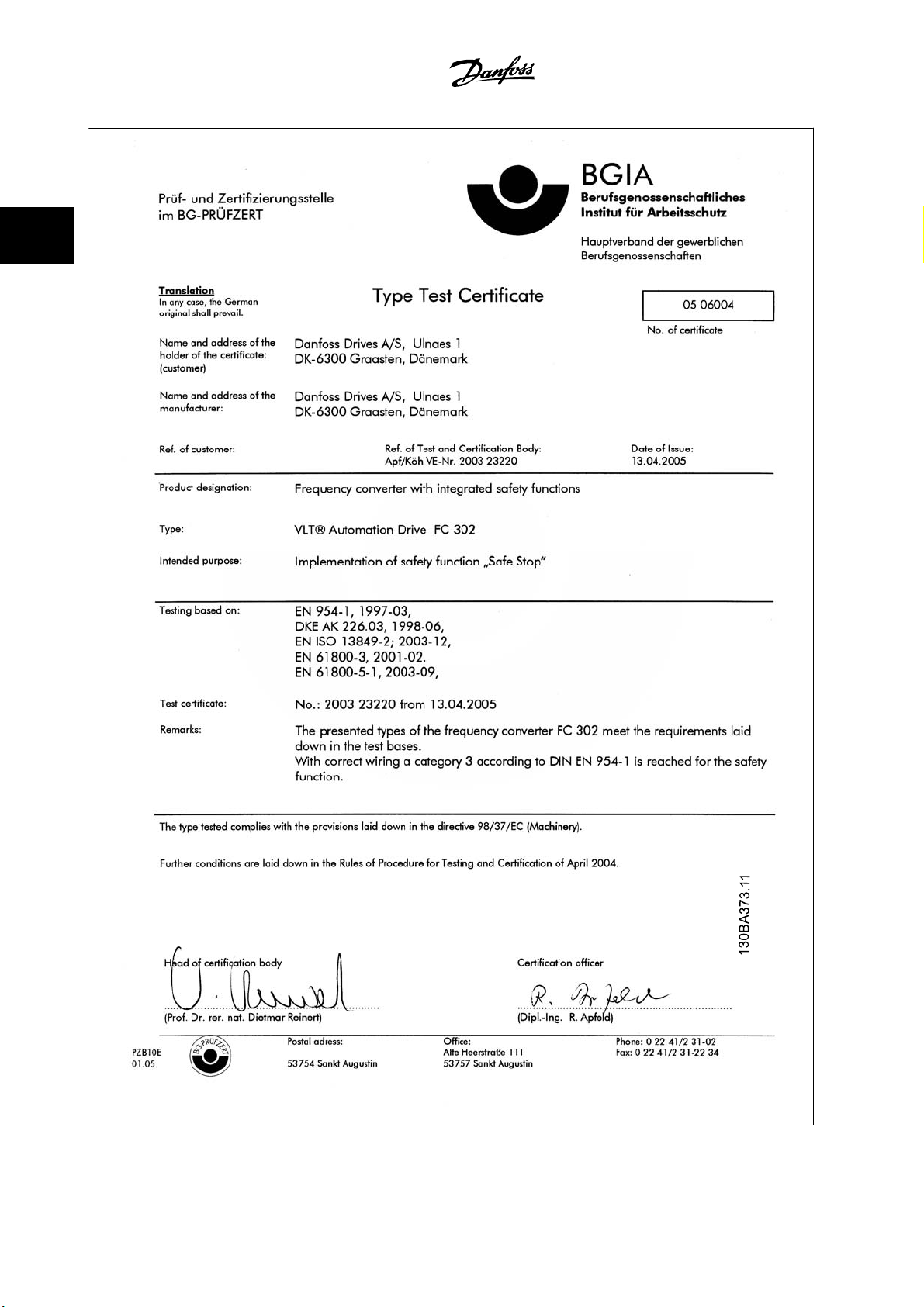
2.1.7 Safe Stop
2 Safety Instructions and General Warning
The FC 302 can perform the safety function
It is designed and approved suitable for the requirements of Safety Category 3 in EN 954-1. This functionality is called Safe Stop. The information and
instructions of the Instruction Manual are not sufficient for a correct and safe use of the Safe Stop functionality! In order to install and use the safe stop
function in accordance with the requirements of Safety Category 3 in EN 954-1, the related information and instructions of the FC 300 Design Guide MG.
33.BX.YY must be followed! The information and instructions of the Instruction Manual are not sufficient for a correct and safe use of the safe stop
functionality!
Safe Torque Off
(As defined by draft CD IEC 61800-5-2) or
Stop Category 0
(as defined in EN 60204-1).
2
MG.33.U3.22 - VLT® is a registered Danfoss trademark
2-3
2
2 Safety Instructions and General Warning
VLT® Automation Drive FC 300
Instruction Manual High Power
2-4
MG.33.U3.22 - VLT® is a registered Danfoss trademark

VLT® Automation Drive FC 300
Instruction Manual High Power
2.1.8 Safe Stop Installation
To carry out an installation of a Category 0 Stop (EN60204) in conformity with Safety Category 3 (EN954-1), follow these instructions:
1. The bridge (jumper) between Terminal 37 and 24 V DC must be removed. Cutting or breaking the jumper is not sufficient. Remove it entirely
to avoid short-circuiting. See jumper on illustration.
2. Connect terminal 37 to 24 V DC by a short circuit-protected cable. The 24 V DC voltage supply must be interruptible by an EN954-1 category 3
circuit interrupt device. If the interrupt device and the adjustable frequency drive are placed in the same installation panel, you can use a non-
shielded cable instead of a shielded one.
2 Safety Instructions and General Warning
2
Figure 2.1: Bridge jumper between terminal 37 and 24 VDC
The illustration below shows a Stopping Category 0 (EN 60204-1) with safety Category 3 (EN 954-1). The circuit interruption is caused by an opening
door contact. The illustration also shows how to connect a non-safety-related hardware coast.
Figure 2.2: Illustration of the essential aspects of an installation to achieve a Stopping Category 0 (EN 60204-1) with safety Category 3 (EN
954-1).
MG.33.U3.22 - VLT® is a registered Danfoss trademark
2-5

2 Safety Instructions and General Warning
2.1.9 IT Line Power
VLT® Automation Drive FC 300
Instruction Manual High Power
2
Par. 14-50
is done, it will reduce the RFI performance to A2 level. For the 525–690 V adjustable frequency drives, par. 14-50
cannot be opened.
RFI 1
can be used to disconnect the internal RFI capacitors from the RFI filter to ground in the 380–500 V adjustable frequency drives. If this
RFI 1
has no function. The RFI switch
2-6
MG.33.U3.22 - VLT® is a registered Danfoss trademark

VLT® Automation Drive FC 300
Instruction Manual High Power
3How to Install
3.1 Pre-installation
3.1.1 Planning the Installation Site
3 How to Install
NOTE!
Before performing the installation, it is important to plan the installation of the adjustable frequency drive. Neglecting this may result
in extra work during and after installation.
Select the best possible operation site by considering the following (see details on the following pages and in the respective Design
Guides):
• Ambient operating temperature
• Installation method
• How to cool the unit
• Position of the adjustable frequency drive.
•Cable routing
• Ensure the power source supplies the correct voltage and necessary current.
• Ensure that the motor current rating is within the maximum current from the adjustable frequency drive.
• If the adjustable frequency drive is without built-in fuses, ensure that the external fuses are rated correctly.
3.1.2 Receiving the Adjustable Frequency Drive
When receiving the adjustable frequency drive, make sure that the packaging is intact, and look for any damage that might have occurred to the unit
during transport. If damage has occurred, immediately contact the shipping company to make a damage claim.
3
MG.33.U3.22 - VLT® is a registered Danfoss trademark
3-1
3
VLT® Automation Drive FC 300
3 How to Install
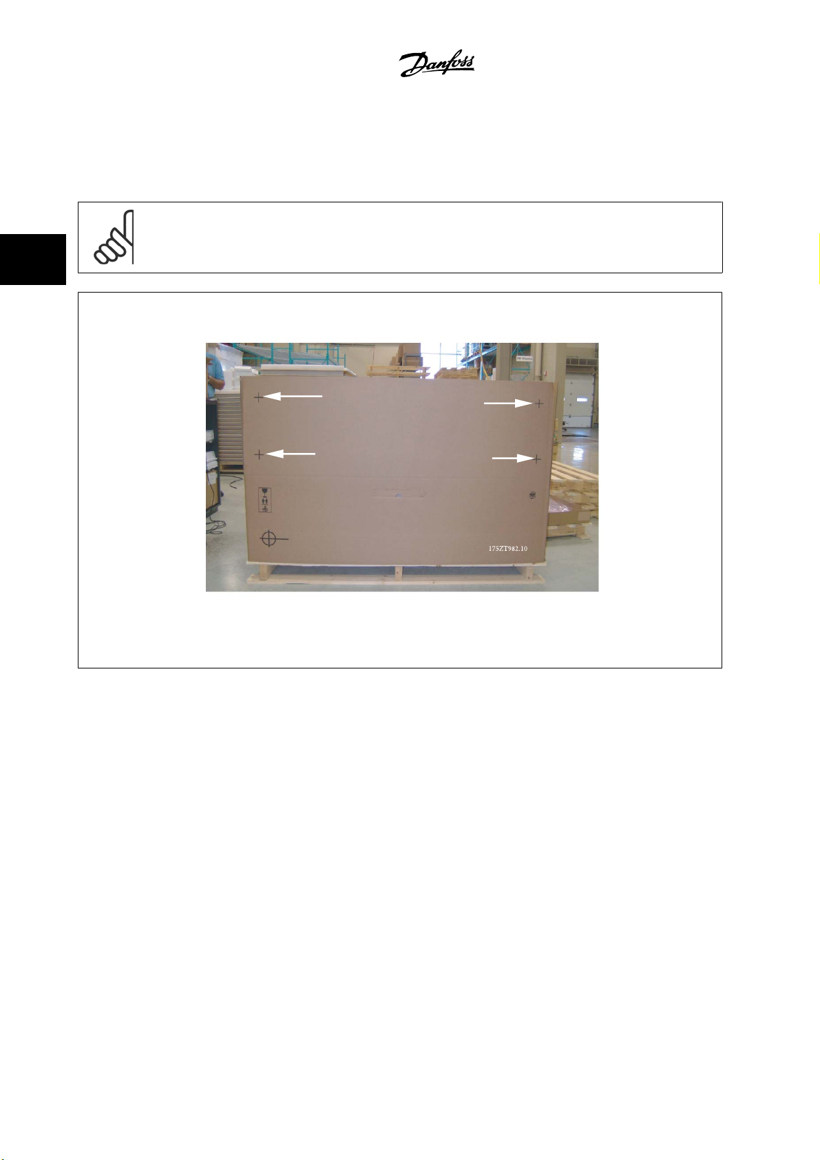
3.1.3 Transportation and Unpacking
Before unpacking the adjustable frequency drive, it is recommended to unload it as close as possible to the final installation site.
Remove the box and handle the adjustable frequency drive on the pallet, as long as possible.
NOTE!
The card box cover contains a drilling master for the mounting holes in the D frames. For the E size, please refer to section
Dimensions
later in this chapter.
Instruction Manual High Power
Mechanical
Figure 3.1: Mounting Template
3-2
MG.33.U3.22 - VLT® is a registered Danfoss trademark
VLT® Automation Drive FC 300
Instruction Manual High Power
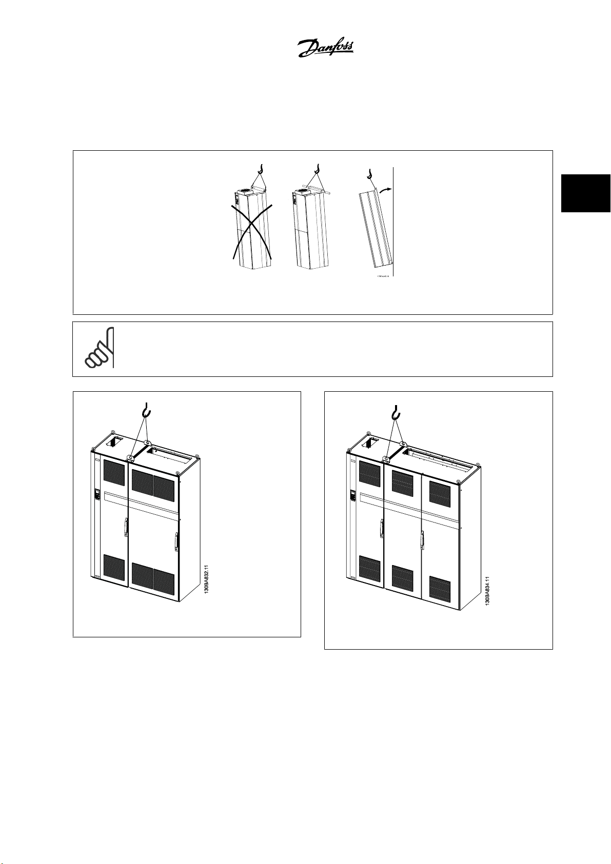
3.1.4 Lifting
Always lift the adjustable frequency drive using the dedicated lifting holes. For all D and E2 (IP00) enclosures, use a bar to avoid bending the lifting holes
of the adjustable frequency drive.
Figure 3.2: Recommended lifting method, frame sizes D and E .
NOTE!
The lifting bar must be able to handle the weight of the adjustable frequency drive. See
different frame sizes. Maximum diameter for bar is 1 in [2.5 cm]. The angle from the top of the drive to the lifting cable should be
60° C or greater.
Mechanical Dimensions
3 How to Install
for the weight of the
3
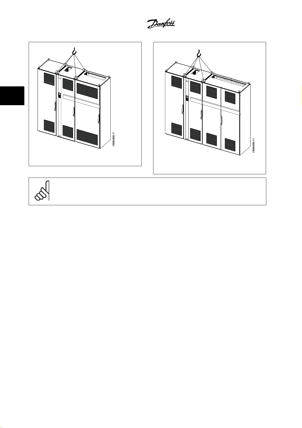
Figure 3.3: Recommended lifting method, frame size F1.
MG.33.U3.22 - VLT® is a registered Danfoss trademark
Figure 3.4: Recommended lifting method, frame size F2.
3-3
3
3 How to Install
Figure 3.5: Recommended lifting method, frame size F3.
VLT® Automation Drive FC 300
Instruction Manual High Power
Figure 3.6: Recommended lifting method, frame size F4.
NOTE!
Note the plinth is provided in the same packaging as the adjustable frequency drive but is not attached to frame sizes F1-F4 during
shipment. The plinth is required to allow airflow to the drive to provide proper cooling. The F frames should be positioned on top of
the plinth in the final installation location. The angle from the top of the drive to the lifting cable should be 60° C or greater.
3-4
MG.33.U3.22 - VLT® is a registered Danfoss trademark
VLT® Automation Drive FC 300
Instruction Manual High Power
3 How to Install
3
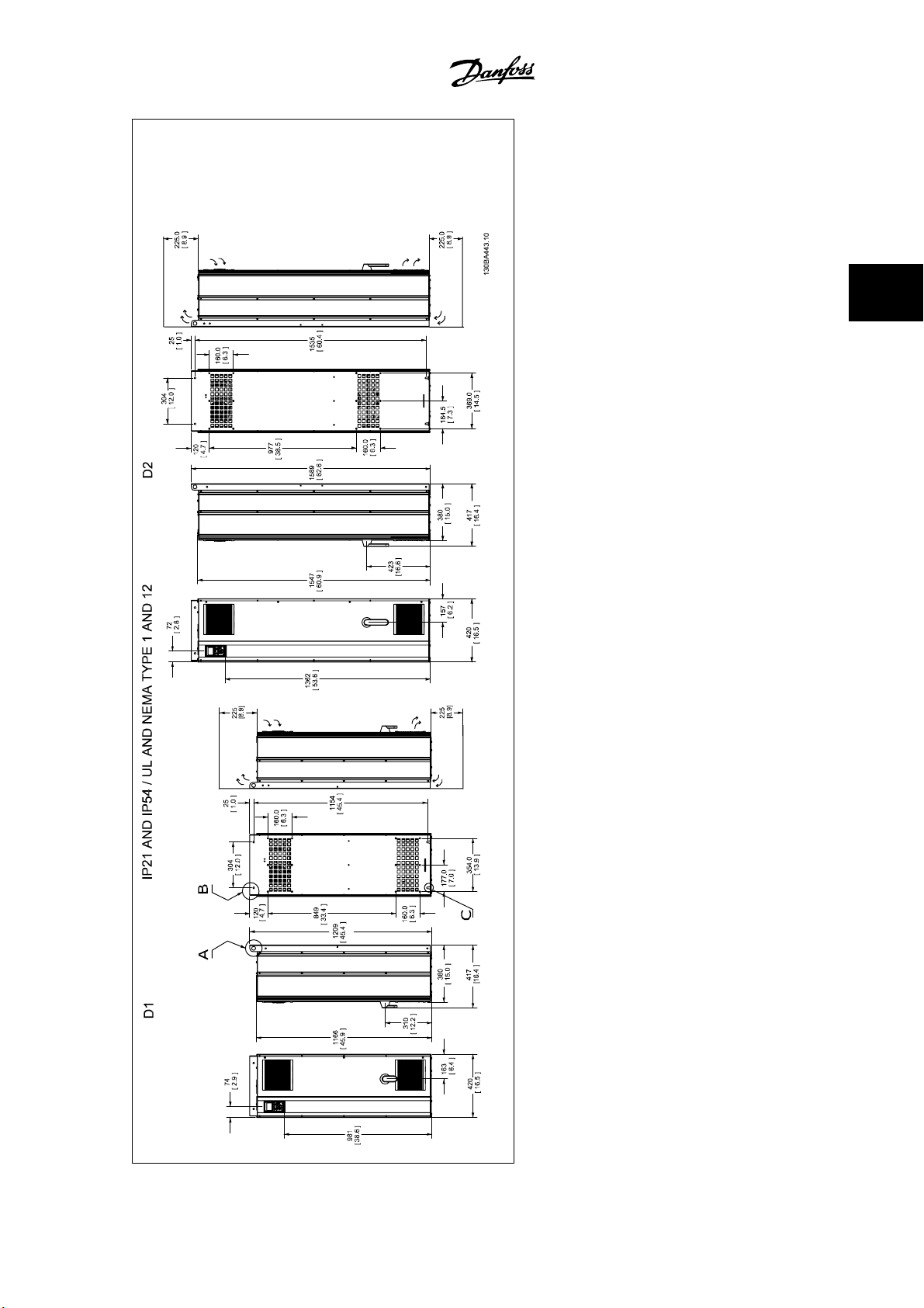
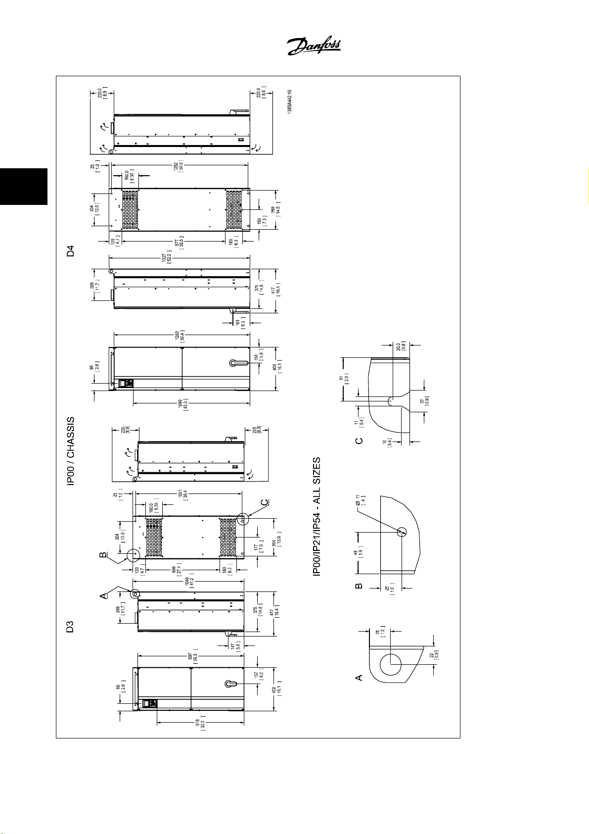
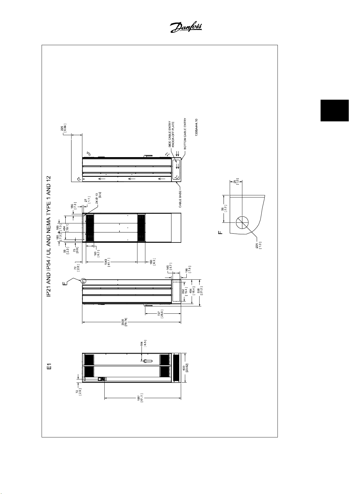
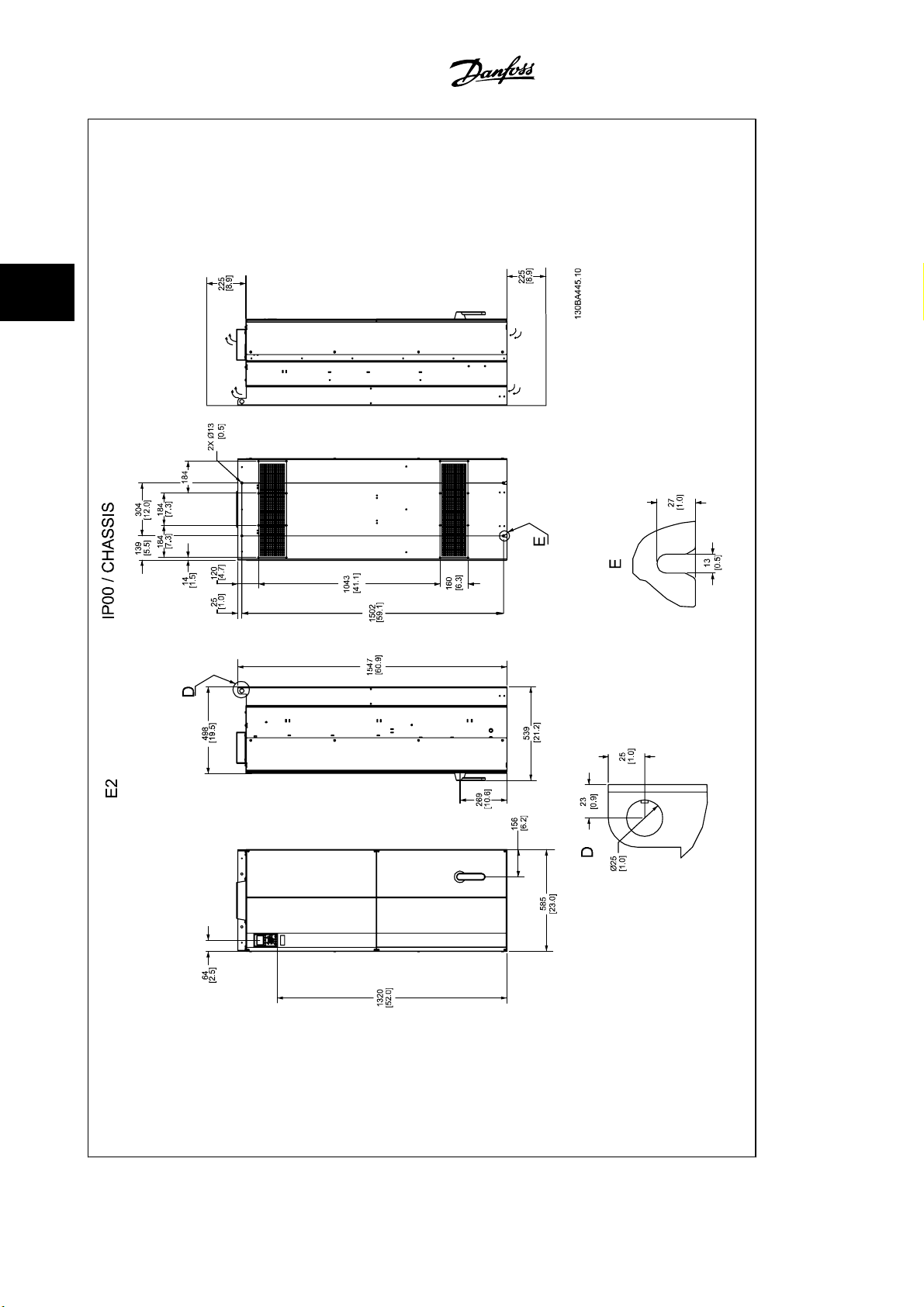
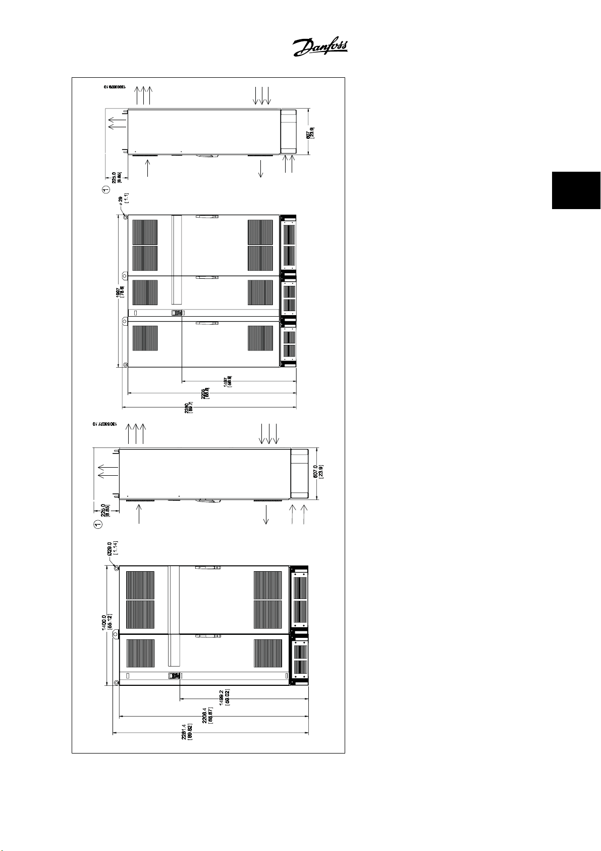
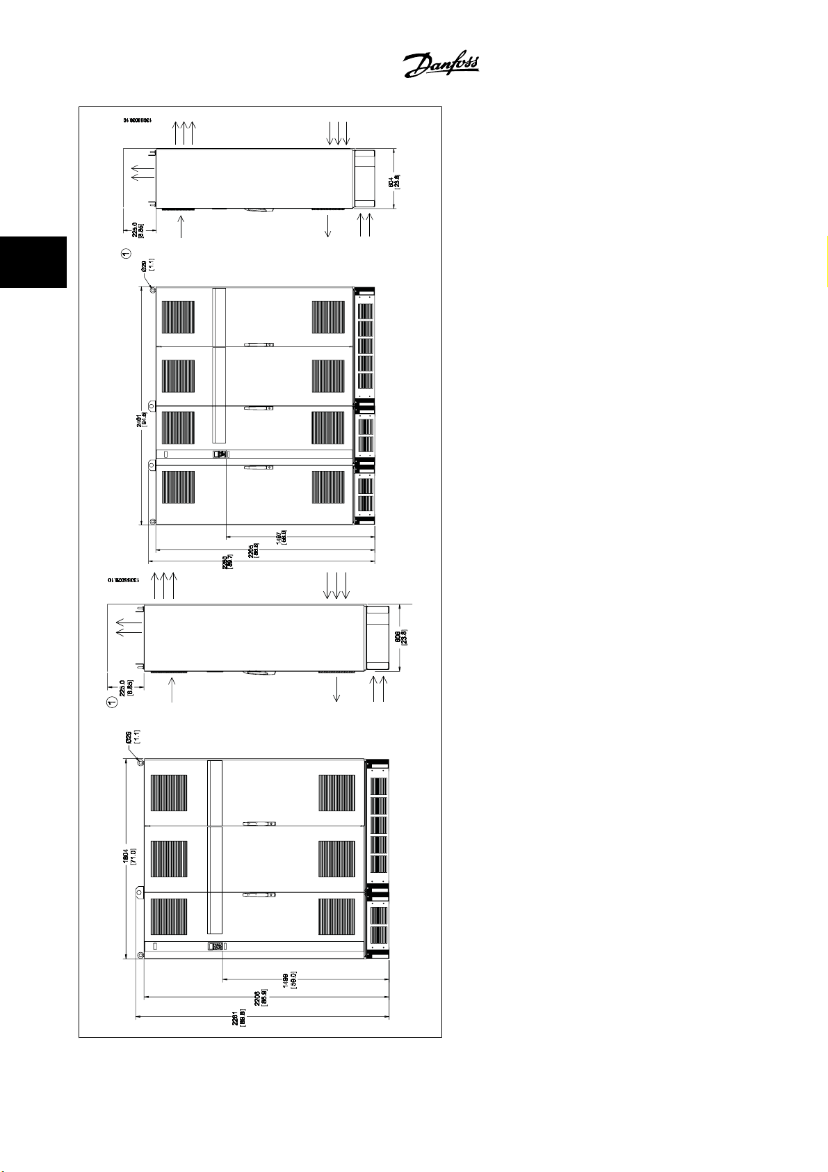
3.1.5 Mechanical Dimensions
Please note airflow directions
*
MG.33.U3.22 - VLT® is a registered Danfoss trademark
3-5
3
3 How to Install
VLT® Automation Drive FC 300
Instruction Manual High Power
3-6
MG.33.U3.22 - VLT® is a registered Danfoss trademark
Please note airflow directions
*
VLT® Automation Drive FC 300
Instruction Manual High Power
3 How to Install
3
MG.33.U3.22 - VLT® is a registered Danfoss trademark
Please note airflow directions
*
3-7
3
3 How to Install
VLT® Automation Drive FC 300
Instruction Manual High Power
3-8
MG.33.U3.22 - VLT® is a registered Danfoss trademark
Please note airflow directions
*
VLT® Automation Drive FC 300
Instruction Manual High Power
3 How to Install
3
F1 IP 21/54 - NEMA 1/12 F3 IP 21/54 - NEMA 1/12
1) Minimum clearance from ceiling
MG.33.U3.22 - VLT® is a registered Danfoss trademark
3-9
3
3 How to Install
VLT® Automation Drive FC 300
Instruction Manual High Power
F2 IP 21/54 - NEMA 1/12 F4 IP 21/54 - NEMA 1/12
3-10
1) Minimum clearance from ceiling
MG.33.U3.22 - VLT® is a registered Danfoss trademark
VLT® Automation Drive FC 300
Instruction Manual High Power
3 How to Install
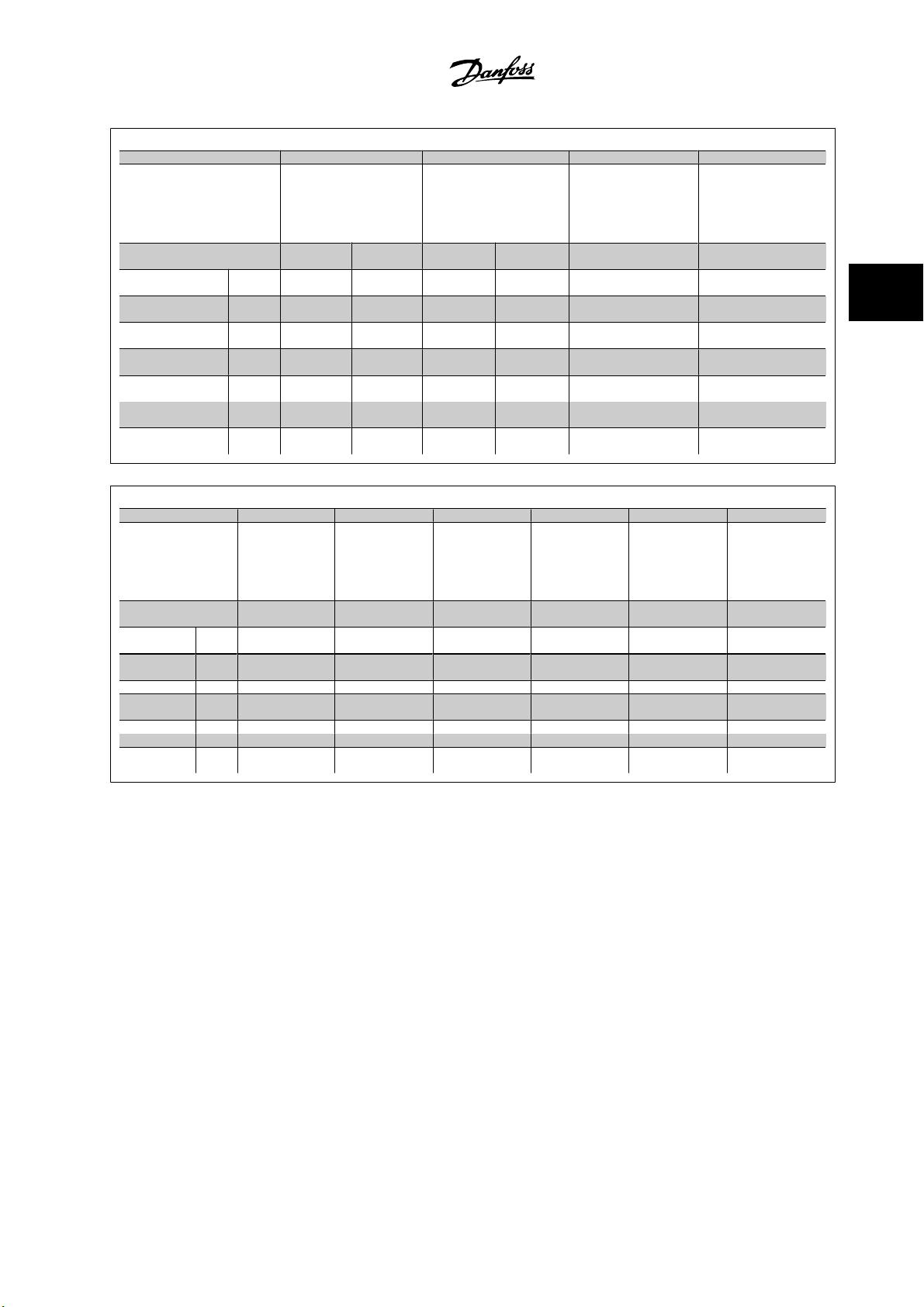
Frame size D1 D2 D3 D4
125–150 hp [90–110
(380 –500 V)
50–175 hp [37–132 kW]
(525–690 V)
IP
NEMA
Shipping dimensions
Drive dimensions Height
Mechanical dimensions, frame sizes E and F
Frame size E1 E2 F1 F2 F3 F4
IP
NEMA
Shipping dimensions
Drive dimensions
Height 25.59 in [650
Width
Depth
Width
Depth 14.96 in [380
Max
weight
Height
Width
Depth 28.98 in [736 mm] 28.98 in [736 mm] 44.5 in [1130 mm] 44.5 in [1130 mm] 44.5 in [1130 mm] 44.5 in [1130 mm]
Height
Width 23.62 in [600 mm] 23.03 in [585 mm] 1400 1800 2000 2400
Depth 19.45 in [494 mm] 19.61 in [498 mm] 606 606 606 606
Max
weight
21
Type 1
mm]
68.11 in
[1730 mm]
22.48 in [570
mm]
47.6 in [1209
mm]
16.54 in [420
mm]
mm]
229.28 lb
[104 kg]
350–550 hp
[250–400 kW]
(380–500 V)
500–750 hp
[355–560 kW]
(525–690 V)
21, 54
Type 12
33.07 in [840 mm] 32.73 in [831 mm]
86.50 in [2197
mm]
78.74 in [2000
mm]
690.05 lb [313 kg] 610.68 lb [277 kg] 1004 1246 1299 1541
Mechanical dimensions, frame size D
kW]
54
Type 12
25.59 in [650
mm]
68.11 in
[1730 mm]
22.48 in [570
mm]
47.6 in [1209
mm]
16.54 in [420
mm]
14.96 in [380
mm]
229.28 lb
[104 kg]
350–550 hp
[250–400 kW]
(380–500 V)
500–750 hp
[355–560 kW]
(525–690 V)
00
Chassis
67.13 in [1705
mm]
60.91 in [1547
mm]
175–300 hp [132–200
250–450 hp [160–315
21
Type 1
25.59 in [650
[1730 mm]
22.48 in [570
[1589 mm]
16.54 in [420
14.96 in [380
332.89 lb
21, 54
Type 12
kW]
(380–500 V)
kW]
(525–690 V)
mm]
68.11 in
mm]
62.56 in
mm]
mm]
[151 kg]
600–850 hp
[450–630 kW]
(380–500 V)
850–1075 hp
[630–800 kW]
(525–690 V)
91.50 in [2324
mm]
61.77 in [1569
mm]
2204 2204 2204 2204
54
Type 12
25.59 in [650
mm]
68.11 in
[1730 mm]
22.48 in [570
mm]
62.56 in
[1589 mm]
16.54 in [420
mm]
14.96 in [380
mm]
332.89 lb
[151 kg]
950–1075 hp
[710–800 kW]
(380–500 V)
1200–1350 hp
[900–1200 kW]
(525–690 V)
21, 54
Type 12
91.50 in [2324
77.24 in [1962
125–150 hp [90–110
kW]
(380–500 V)
50–175 hp [37–132
kW]
(525–690 V)
00
Chassis
25.59 in [650 mm] 25.59 in [650 mm]
48.03 in [1220 mm] 58.66 in [1490 mm]
22.48 in [570 mm] 22.48 in [570 mm]
41.18 in [1046 mm] 52.24 in [1327 mm]
16.06 in [408 mm] 16.06 in [408 mm]
14.76 in [375 mm] 14.76 in [375 mm]
200.62 lb [91 kg] 304.23 lb [138 kg]
600–850 hp
[450–630 kW]
(380–500 V)
850–1075 hp
[630–800 kW]
(525–690 V)
21, 54
Type 12
mm]
mm]
91.50 in [2324
85 in [2159 mm]
175–300 hp [132–200
kW]
(380–500 V)
250–450 hp [160–315
kW]
(525–690 V)
00
Chassis
950–1075 hp
[710–800 kW]
(380–500 V)
1200–1350 hp
[900–1200 kW]
(525–690 V)
21, 54
Type 12
91.50 in [2324
mm]
100.75 in [2559
mm]
mm]
3
MG.33.U3.22 - VLT® is a registered Danfoss trademark
3-11
3
VLT® Automation Drive FC 300
3 How to Install
3.1.6 Rated Power
Frame size D1 D2 D3 D4
Instruction Manual High Power
Enclosure
protection
High overload rated
power - 160% over-
load torque
Frame size E1 E2 F1/F3 F2/F4
IP
NEMA Type 1/ Type 12 Type 1/ Type 12 Chassis Chassis
125–150 hp [90–110 kW] at
50–175 hp [37–132 kW] at
21/54 21/54 00 00
400 V
(380–500 V)
690 V
(525–690 V)
175–300 hp [132–200 kW] at
400 V
(380–500 V)
250–450 hp [160–315 kW] at
690 V
(525–690 V)
125–150 hp [90–110 kW] at
400 V
(380–500 V)
50–175 hp [37–132 kW] at
690 V
(525–690 V)
175–300 hp [132–200 kW] at
250–450 hp [160–315 kW] at
400 V
(380–500 V)
690 V
(525–690 V)
Enclosure
protection
High overload rat-
ed power - 160%
overload torque
IP
NEMA Type 1/ Type 12 Chassis Type 1/ Type 12 Type 1/ Type 12
3-12
21/54 00 21/54 21/54
350–550 hp [250–400 kW]
at 400 V
(380–500 V)
500–750 hp [355–560 kW]
at 690 V
(525–690 V)
320–550 hp [240–400
kW] at 400 V
(380–500 V)
500–750 hp [355–560
kW] at 690 V
(525–690 V)
MG.33.U3.22 - VLT® is a registered Danfoss trademark
600–850 hp [450–630 kW] at 400
V
(380–500 V)
850–1075 hp [630–800 kW] at 690
V
(525–690 V)
950–1075 hp [710–800] kW at
400 V
(380–500 V)
1200–1600 hp [900–1200 kW] at
690 V
(525–690 V)

VLT® Automation Drive FC 300
Instruction Manual High Power
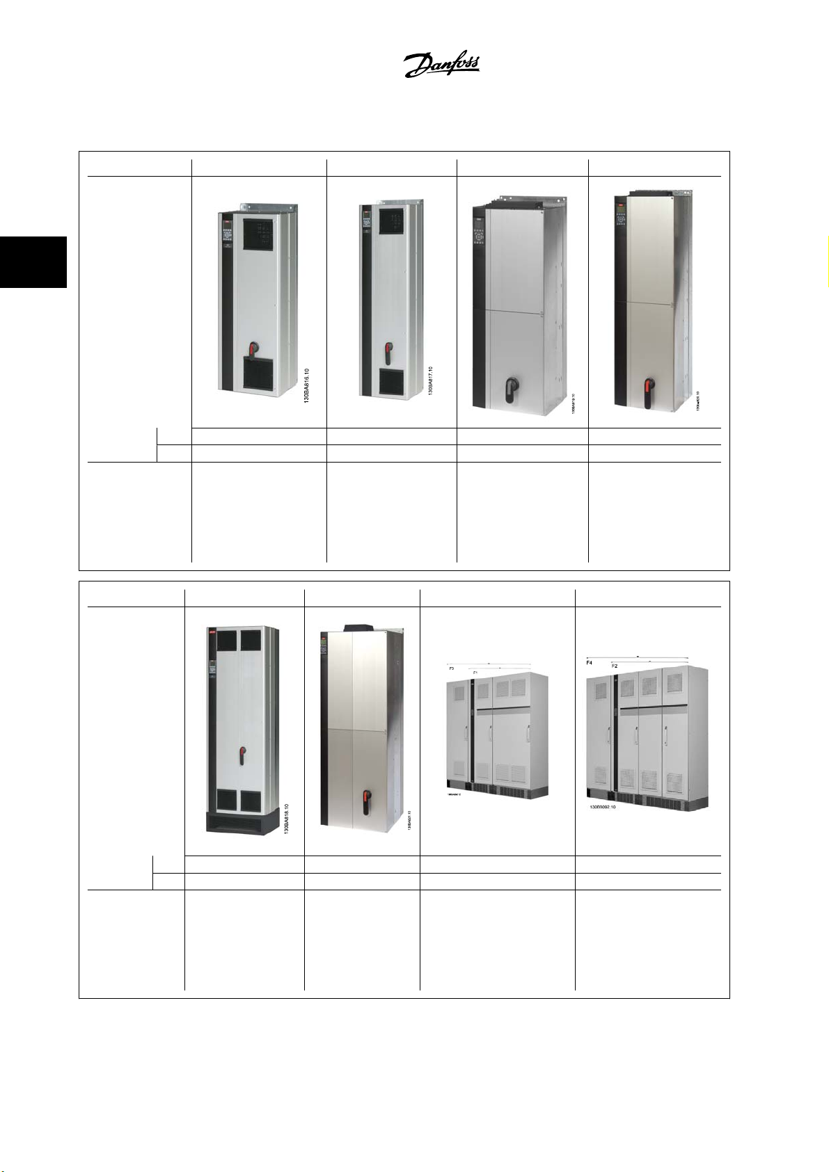
NOTE!
The F enclosures have four different sizes, F1, F2, F3 and F4 The F1 and F2 consist of an inverter cabinet on the right and rectifier
cabinet on the left. The F3 and F4 have an additional options cabinet left of the rectifier cabinet. The F3 is an F1 with an additional
options cabinet. The F4 is an F2 with an additional options cabinet.
3 How to Install
3
MG.33.U3.22 - VLT® is a registered Danfoss trademark
3-13
VLT® Automation Drive FC 300
3 How to Install
Instruction Manual High Power
3.2 Mechanical Installation
Preparation of the mechanical installation of the adjustable frequency drive must be done carefully to ensure proper results and to avoid additional work
during installation. Start by taking a close look at the mechanical drawings at the end of this instruction manual to become familiar with the space demands.
3.2.1 Tools Needed
3
To perform the mechanical installation, the following tools are needed:
• Drill with 0.39 or 0.47 in [10 or 12 mm] drill.
• Tape measure
• Wrench with relevant metric sockets (0.28-0.67 in (7-17 mm))
• Extensions to wrench
• Sheet metal punch for conduits or cable connectors in IP 21/Nema 1 and IP 54 units
• Lifting bar to lift the unit (rod or tube max. Ø1 in [25 mm], able to lift minimum 880 lbs [400 kg].
• Crane or other lifting aid to place the adjustable frequency drive in position
• A Torx T50 tool is needed to install the E1 in IP21 and IP54 enclosure types.
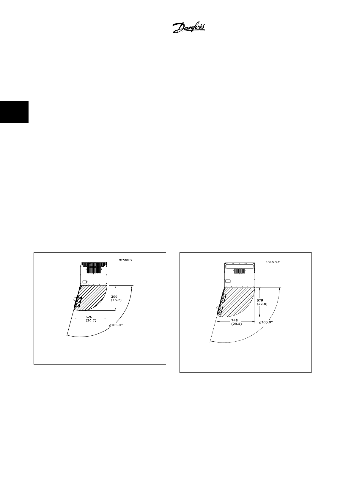
3.2.2 General Considerations
Space
Ensure proper space above and below the adjustable frequency drive to allow airflow and cable access. In addition, space in front of the unit must be
considered to allow the panel door to be opened.
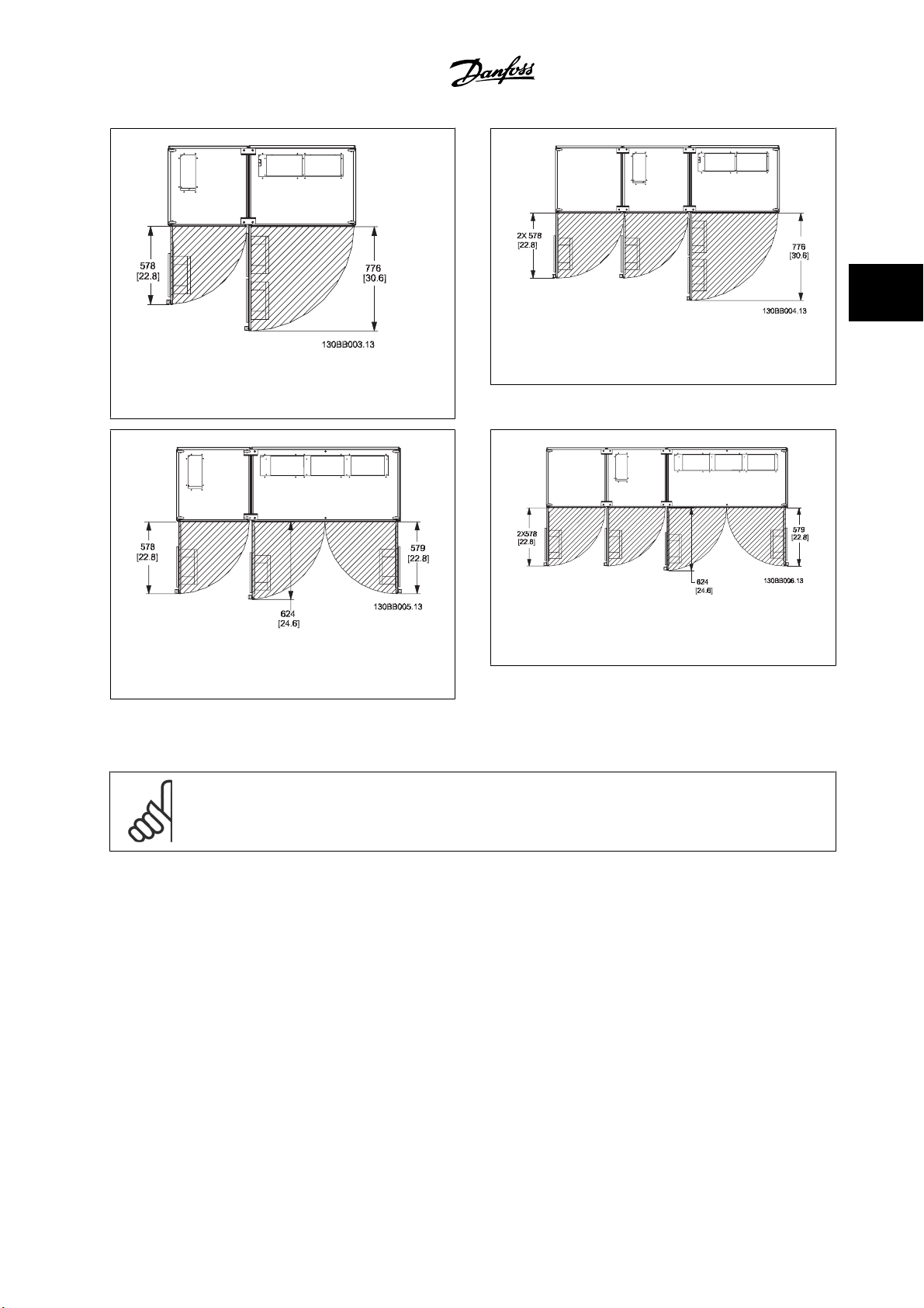
Figure 3.7: Space in front of IP21/IP54 enclosure type,
frame size D1 and D2.
3-14
Figure 3.8: Space in front of IP21/IP54 enclosure type,
frame size E1.
MG.33.U3.22 - VLT® is a registered Danfoss trademark
VLT® Automation Drive FC 300
Instruction Manual High Power
Figure 3.9: Space in front of IP21/IP54 enclosure type,
frame size F1
3 How to Install
3
Figure 3.10: Space in front of IP21/IP54 enclosure type,
frame size F3
Figure 3.12: Space in front of IP21/IP54 enclosure type,
Figure 3.11: Space in front of IP21/IP54 enclosure type,
frame size F2
Wire access
Ensure that proper cable access is present including the necessary bending allowance. As the IP00 enclosure is open to the bottom cables must be fixed
to the back panel of the enclosure where the adjustable frequency drive is mounted, i.e., by using cable clamps.
NOTE!
All cable lugs/shoes must mount within the width of the terminal bus bar.
frame size F4
MG.33.U3.22 - VLT® is a registered Danfoss trademark
3-15
3
3 How to Install
3.2.3 Terminal Locations - Frame size D
Take the following terminal positions into consideration when you design for cable access.
VLT® Automation Drive FC 300
Instruction Manual High Power
Figure 3.13: Position of power connections, frame size D3 and D4
Figure 3.14: Position of power connections with disconnect switch, frame size D1 and D2
Be aware that the power cables are heavy and hard to bend. Give thought to the optimum position of the adjustable frequency drive for ensuring easy
installation of the cables.
NOTE!
All D frames are available with standard input terminals or disconnect switch. All terminal dimensions can be found in the following
table.
3-16
MG.33.U3.22 - VLT® is a registered Danfoss trademark

VLT® Automation Drive FC 300
Instruction Manual High Power
IP 21 (NEMA 1) / IP 54 (NEMA 12) IP 00 / Chassis
Frame size D1 Frame size D2 Frame size D3 Frame size D4
A 277 (10.9) 379 (14.9) 119 (4.7) 122 (4.8)
B 227 (8.9) 326 (12.8) 68 (2.7) 68 (2.7)
C 173 (6.8) 273 (10.8) 15 (0.6) 16 (0.6)
D 179 (7.0) 279 (11.0) 20.7 (0.8) 22 (0.8)
E 370 (14.6) 370 (14.6) 363 (14.3) 363 (14.3)
F 300 (11.8) 300 (11.8) 293 (11.5) 293 (11.5)
G 222 (8.7) 226 (8.9) 215 (8.4) 218 (8.6)
H 139 (5.4) 142 (5.6) 131 (5.2) 135 (5.3)
I 55 (2.2) 59 (2.3) 48 (1.9) 51 (2.0)
J 354 (13.9) 361 (14.2) 347 (13.6) 354 (13.9)
K 284 (11.2) 277 (10.9) 277 (10.9) 270 (10.6)
L 334 (13.1) 334 (13.1) 326 (12.8) 326 (12.8)
M 250 (9.8) 250 (9.8) 243 (9.6) 243 (9.6)
N 167 (6.6) 167 (6.6) 159 (6.3) 159 (6.3)
O 261 (10.3) 260 (10.3) 261 (10.3) 261 (10.3)
P 170 (6.7) 169 (6.7) 170 (6.7) 170 (6.7)
Q 120 (4.7) 120 (4.7) 120 (4.7) 120 (4.7)
R 256 (10.1) 350 (13.8) 98 (3.8) 93 (3.7)
S 308 (12.1) 332 (13.0) 301 (11.8) 324 (12.8)
T 252 (9.9) 262 (10.3) 245 (9.6) 255 (10.0)
U 196 (7.7) 192 (7.6) 189 (7.4) 185 (7.3)
V 260 (10.2) 273 (10.7) 260 (10.2) 273 (10.7)
3 How to Install
3
Table 3.1: Cable positions as shown in the drawings above. Dimensions in mm (inches).
MG.33.U3.22 - VLT® is a registered Danfoss trademark
3-17
3
3 How to Install
3.2.4 Terminal Locations - Frame size E
Terminal Locations - E1
Give thought to the following terminal positions when designing the cable access.
VLT® Automation Drive FC 300
Instruction Manual High Power
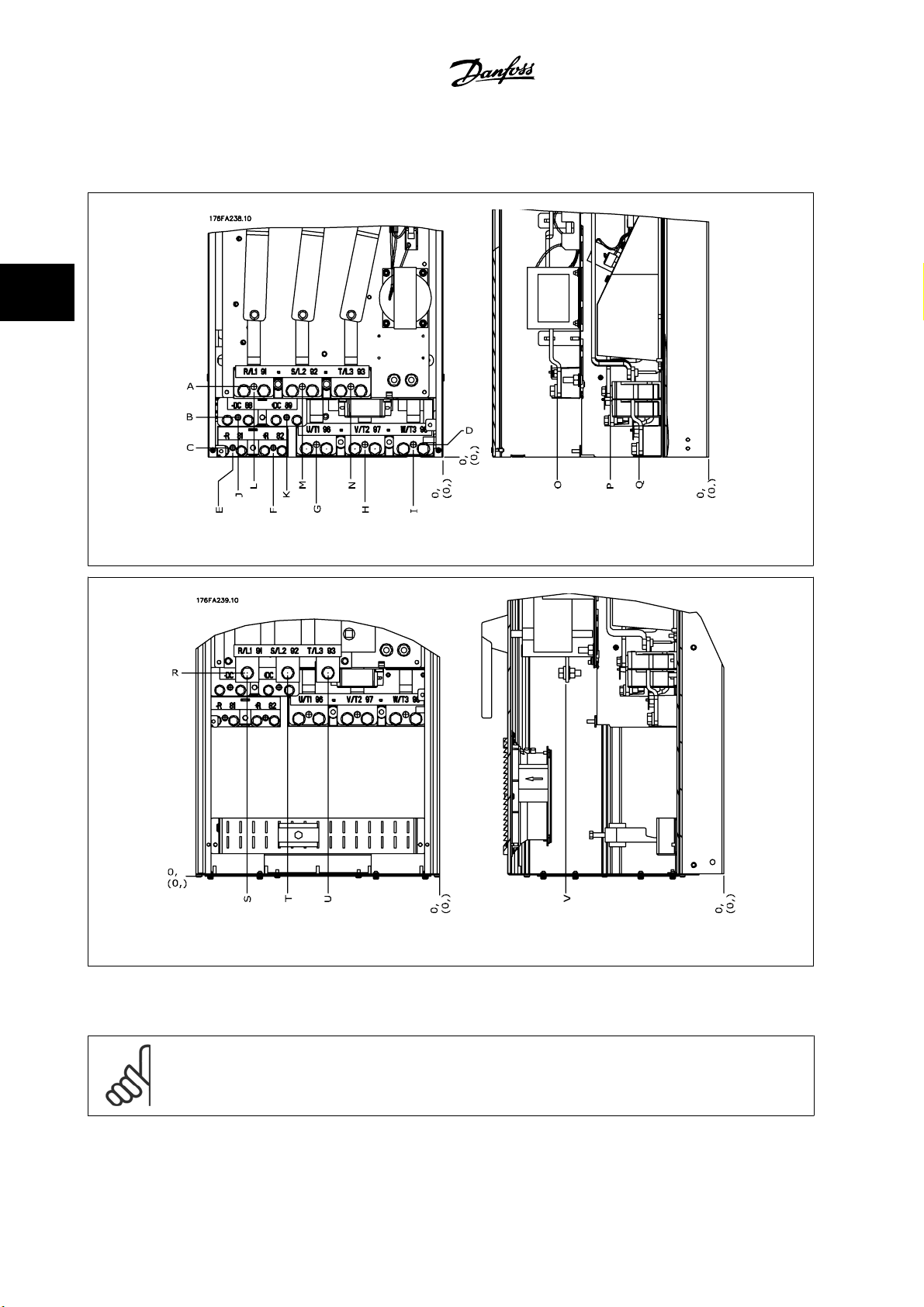
Figure 3.15: IP21 (NEMA Type 1) and IP54 (NEMA Type 12) enclosure power connection positions
Figure 3.16: IP21 (NEMA type 1) and IP54 (NEMA type 12) enclosure power connection positions (detail B)
3-18
MG.33.U3.22 - VLT® is a registered Danfoss trademark

VLT® Automation Drive FC 300
Instruction Manual High Power
3 How to Install
3
Figure 3.17: IP21 (NEMA type 1) and IP54 (NEMA type 12) enclosure power connection position of disconnect switch
Frame
size
E1
IP54/IP21 UL AND NEMA1/NEMA12
350/450 hp [250/315 kW] (400 V) AND
500/600–675/850 hp [355/450–500/630 KW]
450/500–550/600 hp [315/355-400/450 kW]
Unit type Dimension for disconnect terminal
381 (15.0) 253 (9.9) 253 (9.9) 431 (17.0) 562 (22.1) N/A
(690 V)
(400 V)
371 (14.6) 371 (14.6) 341 (13.4) 431 (17.0) 431 (17.0) 455 (17.9)
MG.33.U3.22 - VLT® is a registered Danfoss trademark
3-19

3
3 How to Install
Terminal locations - Frame size E2
Give thought to the following terminal positions when designing the cable access.
VLT® Automation Drive FC 300
Instruction Manual High Power
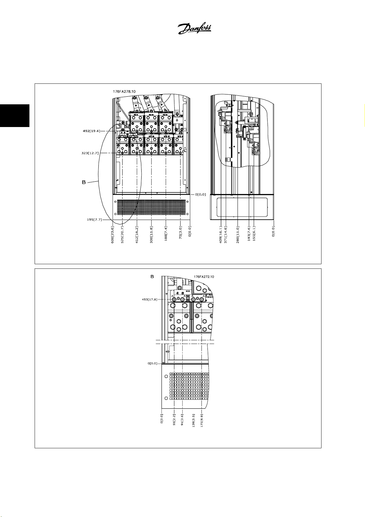
Figure 3.18: IP00 enclosure power connection positions
Figure 3.19: IP00 enclosure power connection positions
3-20
MG.33.U3.22 - VLT® is a registered Danfoss trademark

VLT® Automation Drive FC 300
Instruction Manual High Power
Figure 3.20: IP00 enclosure power connections positions of disconnect switch
3 How to Install
3
Note that the power cables are heavy and difficult to bend. Give thought to the optimum position of the adjustable frequency drive for ensuring easy
installation of the cables.
Each terminal allows for the use of up to 4 cables with cable lugs or the use of standard box lug. Ground is connected to relevant termination point in
the drive.
Figure 3.21: Terminal in details
NOTE!
Power connections can be made to positions A or B
MG.33.U3.22 - VLT® is a registered Danfoss trademark
3-21

3 How to Install
VLT® Automation Drive FC 300
Instruction Manual High Power
3
Frame
size
E2
350/450 hp [250/315 kW] (400 V) AND
500/600–675/850 hp [355/450–500/630 KW]
450/500–550/600 hp [315/355-400/450 kW]
Unit type Dimension for disconnect terminal
IPOO/CHASSIS A B C D E F
(690 V)
(400 V)
3.2.5 Terminal Locations - Frame size F
NOTE!
The F frames have four different sizes, F1, F2, F3 and F4. The F1 and F2 consist of an inverter cabinet on the right and rectifier cabinet
on the left. The F3 and F4 have an additional options cabinet left of the rectifier cabinet. The F3 is an F1 with an additional options
cabinet. The F4 is an F2 with an additional options cabinet.
Terminal locations - Frame size F1 and F3
381 (15.0) 245 (9.6) 334 (13.1) 423 (16.7) 256 (10.1) N/A
383 (15.1) 244 (9.6) 334 (13.1) 424 (16.7) 109 (4.3) 149 (5.8)
Figure 3.22: Terminal locations - Inverter Cabinet - F1 and F3 (front, left and right side view). The connector plate is 1.65 in [42 mm] below .
0 level.
1) Earth ground bar
2) Motor terminals
3) Brake terminals
3-22
MG.33.U3.22 - VLT® is a registered Danfoss trademark

VLT® Automation Drive FC 300
Instruction Manual High Power
Terminal locations - Frame size F2 and F4
3 How to Install
3
Figure 3.23: Terminal locations - Inverter cabinet - F2 and F4 (front, left and right side view). The connector plate is 1.65 in [42 mm] below .
0 level.
1) Earth ground bar
MG.33.U3.22 - VLT® is a registered Danfoss trademark
3-23

3
3 How to Install
Terminal locations - Rectifier (F1, F2, F3 and F4)
VLT® Automation Drive FC 300
Instruction Manual High Power
Figure 3.24: Terminal locations - Rectifier (left side, front and right side view). The connector plate is 1.65 in [42 mm] below .0 level.
1) Load Share Terminal (-)
2) Earth ground bar
3) Load Share Terminal (+)
Terminal locations - Options cabinet (F3 and F4)
Figure 3.25: Terminal locations - Options cabinet (left side, front and right side view). The connector plate is 1.65 in [42 mm] below .0 level.
1) Earth ground bar
3-24
MG.33.U3.22 - VLT® is a registered Danfoss trademark

VLT® Automation Drive FC 300
Instruction Manual High Power
Terminal locations - Options Cabinet with circuit breaker/ molded case switch (F3 and F4)
Figure 3.26: Terminal locations - Options cabinet with circuit breaker/ molded case switch (left side, front and right side view). The connector
plate is 1.65 in [42 mm] below .0 level.
1) Earth ground bar
3 How to Install
3
Power size 2345
450 kW (480 V), 630–710 kW
(690 V)
500–800 kW (480 V), 800–
1000 kW (690 V)
Table 3.2: Dimension for terminal
34.9 86.9 122.2 174.2
46.3 98.3 119.0 171.0
MG.33.U3.22 - VLT® is a registered Danfoss trademark
3-25

3
VLT® Automation Drive FC 300
3 How to Install
3.2.6 Cooling and Airflow
Cooling
Cooling can be obtained in different ways, by using the cooling ducts in the bottom and the top of the unit, by taking air in and out the back of the unit
or by combining the cooling possibilities.
Duct cooling
A dedicated option has been developed to optimize installation of IP00/chassis adjustable frequency drives in Rittal TS8 enclosures utilizing the fan of
the adjustable frequency drive for forced air cooling of the backchannel. The air out the top of the enclosure could but ducted outside a facility so the
heat losses from the backchannel are not dissipated within the control room reducing air-conditioning requirements of the facility.
Please see
Back cooling
The backchannel air can also be ventilated in and out the back of a Rittal TS8 enclosure. This offers a solution where the backchannel could take air from
outside the facility and return the heat losses outside the facility thus reducing air-conditioning requirements.
Installation of Duct Cooling Kit in Rittal enclosures
NOTE!
A door fan is required on the enclosure to remove the heat losses not contained in the backchannel of the drive and any additional
losses generated from other components installed inside the enclosure. The total required airflow must be calculated so that the
appropriate fans can be selected. Some enclosure manufacturers offer software for performing the calculations (e.g., Rittal Therm
software). If the VLT is the only heat generating component in the enclosure, the minimum airflow required at an ambient temperature
of 113°F [45°C] for the D3 and D4 drives is 391 m
3
[45°C] for the E2 drive is 782 m
/h (460 cfm).
, for further information.
3
/h (230 cfm). The minimum airflow required at an ambient temperature of 113°F
Instruction Manual High Power
Airflow
The necessary airflow over the heatsink must be ensured. The flow rate is shown below.
Enclosure protection
IP21 / NEMA 1
IP54 / NEMA 12
IP21 / NEMA 1 F1, F2, F3 and F4
IP54 / NEMA 12 F1, F2, F3 and F4
IP00 / Chassis D3 and D4
* Airflow per fan. Frame size F contain multiple fans.
Table 3.3: Heatsink Airflow
NOTE!
The fan runs for the following reasons:
1. AMA
2. DC Hold
3. Pre-Mag
4. DC Brake
5. 60% of nominal current is exceeded
6. Specific heatsink temperature exceeded (power-size dependent).
Once the fan is started, it will run for a minimum of 10 minutes.
Frame size Door fan(s) / Top fan airflow Heatsink fan(s)
D1 and D2
E1 P250T5, P355T7, P400T7
E1 P315-P400T5, P500-P560T7
E2 P250T5, P355T7, P400T7
E2 P315-P400T5, P500-P560T7
170 m3/h (100 cfm) 765 m3/h (450 cfm)
3
/h (200 cfm) 1105 m3/h (650 cfm)
340 m
340 m3/h (200 cfm) 1445 m3/h (850 cfm)
3
/h (412 cfm)* 985 m3/h (580 cfm)*
700 m
525 m3/h (309 cfm)* 985 m3/h (580 cfm)*
3
/h (150 cfm) 765 m3/h (450 cfm)
255 m
255 m3/h (150 cfm) 1105 m3/h (650 cfm)
3
/h (150 cfm) 1445 m3/h (850 cfm)
255 m
3-26
MG.33.U3.22 - VLT® is a registered Danfoss trademark

VLT® Automation Drive FC 300
Instruction Manual High Power
External ducts
If additional duct work is added externally to the Rittal cabinet, the pressure drop in the ducting must be calculated. Use the charts below to derate the
adjustable frequency drive according to the pressure drop.
Figure 3.27: D frame Derating vs. Pressure Change
3
Drive airflow: 450 cfm (765 m
/h)
3 How to Install
3
Figure 3.28: E frame Derating vs. Pressure Change (Small Fan), P250T5 and P355T7-P400T7
3
Drive airflow: 650 cfm (1105 m
Figure 3.29: E frame Derating vs. Pressure Change (Large Fan), P315T5-P400T5 and P500T7-P560T7
Drive airflow: 850 cfm (1445 m
/h)
3
/h)
MG.33.U3.22 - VLT® is a registered Danfoss trademark
3-27

3 How to Install
VLT® Automation Drive FC 300
Instruction Manual High Power
3
Figure 3.30: F1, F2, F3, F4 frame Derating vs. Pressure Change
Drive airflow: 580 cfm (985 m
3
/h)
3.2.7 Installation on the wall - IP21 (NEMA 1) and IP54 (NEMA 12) Units
This only applies to frame sizes D1 and D2 . Thought must be given to where the unit should be installed.
Take the relevant points into consideration before you select the final installation site:
• Clearance space for cooling
• Clearance for opening the door
• Cable entry clearance from the bottom
Mark the mounting holes carefully using the mounting template on the wall, and drill the holes as indicated. Ensure proper distance to the floor and the
ceiling for cooling. A minimum of 8.9 in [225 mm] below the adjustable frequency drive is needed. Mount the bolts at the bottom and lift the adjustable
frequency drive up on the bolts. Tilt the adjustable frequency drive against the wall and mount the upper bolts. Tighten all four bolts to secure the
adjustable frequency drive against the wall.
Figure 3.31: Lifting method for mounting drive on wall
3-28
MG.33.U3.22 - VLT® is a registered Danfoss trademark

VLT® Automation Drive FC 300
Instruction Manual High Power
3.2.8 Connector/Conduit Entry - IP21 (NEMA 1) and IP54 (NEMA12)
Cables are connected through the connector plate from the bottom. Remove the plate and plan where to place the entry for the connectors or conduits.
Prepare holes in the marked area on the drawing.
NOTE!
The connector plate must be fitted to the adjustable frequency drive to ensure the specified protection degree, as well as ensuring
proper cooling of the unit. If the connector plate is not mounted, the adjustable frequency drive may trip on Alarm 69, Pwr. Card Temp
3 How to Install
3
Figure 3.32: Example of proper installation of the connector plate.
Frame size D1 + D2
Frame size E1
Cable entries viewed from the bottom of the adjustable frequency drive - 1) Line power side 2) Motor side
MG.33.U3.22 - VLT® is a registered Danfoss trademark
3-29

3
3 How to Install
Frame size F1
Frame size F2
VLT® Automation Drive FC 300
Instruction Manual High Power
Frame size F3
Frame size F4
F1-F4: Cable entries viewed from the bottom of the adjustable frequency drive - 1) Place conduits in marked areas
3-30
MG.33.U3.22 - VLT® is a registered Danfoss trademark

VLT® Automation Drive FC 300
Instruction Manual High Power
Figure 3.33: Mounting of bottom plate,frame size E1.
The bottom plate of the E1 can be mounted from either inside or outside of the enclosure, allowing flexibility in the installation process, i.e., if mounted
from the bottom the connectors and cables can be mounted before the adjustable frequency drive is placed on the pedestal.
3 How to Install
3
3.2.9 IP21 Drip Shield Installation (Frame size D1 and D2 )
To comply with the IP21 rating, a separate drip shield is to be
installed as explained below:
• Remove the two front screws.
• Insert the drip shield and replace the screws.
• Torque the screws to 5.6 Nm (50 in-lbs).
Figure 3.34: Install the drip shield.
MG.33.U3.22 - VLT® is a registered Danfoss trademark
3-31

3
VLT® Automation Drive FC 300
3 How to Install
Instruction Manual High Power
3.3 Field Installation of Options
3.3.1 Installation of Duct Cooling Kit in Rittal Enclosures
This section deals with the installation of IP00 / chassis enclosed adjustable frequency drives with duct work cooling kits in Rittal enclosures. In addition
to the enclosure an 8 in [200 mm] base/plinth is required.
Figure 3.35: Installation of IP00 in Rittal TS8 enclosure.
The minimum enclosure dimension is:
• D3 and D4 frame: Depth 19.7 in [500 mm] and width 23.6 in [600 mm].
• E2 frame: Depth 23.6 in [600 mm] and width 31.5 in [800 mm].
The maximum depth and width are as required for the installation. When using multiple adjustable frequency drives in one enclosure it is recommended
that each drive is mounted on its own back panel and supported along the mid-section of the panel. These duct work kits do not support the “in frame”
mounting of the panel (see Rittal TS8 catalog for details). The duct work cooling kits listed in the table below are suitable for us e o nl y w ith IP 00 / Chassis
adjustable frequency drives in Rittal TS8 IP 20 and UL and NEMA 1 and IP 54 and UL and NEMA 12 enclosures.
For the E2 frames, it is important to mount the plate at the absolute rear of the Rittal enclosure due to the weight of the adjustable
frequency drive.
3-32
MG.33.U3.22 - VLT® is a registered Danfoss trademark

VLT® Automation Drive FC 300
Instruction Manual High Power
NOTE!
A door fan is required on the enclosure to remove the heat losses not contained in the backchannel of the drive and any additional
losses generated from other components installed inside the enclosure. The total required air flow must be calculated so that the
appropriate fans can be selected. Some enclosure manufacturers offer software for performing the calculations (i.e., Rittal Therm
software). If the VLT is the only heat generating component in the enclosure, the minimum airflow required at an ambient temperature
of 113°F [45°C] for the D3 and D4 drives is 391 m
[45°C] for the E2 drive is 782 m
3
/h (460 cfm).
3 How to Install
3
/h (230 cfm). The minimum airflow required at an ambient temperature of 113°F
Ordering Information
Rittal TS-8 Enclosure
70.9 in [1800 mm] 176F1824 176F1823 Not possible
78.7 in [2000 mm] 176F1826 176F1825 176F1850
86.6 in [2200 mm] 176F0299
NOTE!
Please see the
External ducts
If additional duct work is added externally to the Rittal cabinet, the pressure drop in the ducting must be calculated. Please see the section
Airflow
for further information.
Frame D3 Kit Part No. Frame D4Kit Part No. Frame E2 Part No.
Duct Kit Instruction Manual, 175R5640,
for further information
Cooling and
3.3.2 Installation of Top-only Duct Cooling Kit
This description is for the installation of the top section only of the backchannel cooling kits available for frame sizes D3, D4 and E2. In addition to the
enclosure, an 8 in [200 mm] vented pedestal is required.
The minimum enclosure depth is 19.7 in [500 mm] (23.6 in [600 mm] for E2 frame) and the minimum enclosure width is 23.6 in [600 mm] (31.5 in [800
mm] for E2 frame). The maximum depth and width are as required for the installation. When using multiple adjustable frequency drives in one enclosure
mount each drive on its own back panel and support along the mid-section of the panel. The back-channel cooling kits are very similar in construction
for all frames. The D3 and D4 kits do not support “in frame” mounting of the adjustable frequency drives. The E2 kit is mounted “in frame” for additional
support of the adjustable frequency drive.
Using these kits as described removes 85% of the losses via the backchannel using the drive’s main heatsink fan. The remaining 15% must be removed
via the door of the enclosure.
3
NOTE!
Please see the
Ordering information
Frame size D3 and D4: 176F1775
Frame size E2: 176F1776
Top-Only Backchannel Cooling Kit Instruction, 175R1107,
MG.33.U3.22 - VLT® is a registered Danfoss trademark
for further information
3-33

3
VLT® Automation Drive FC 300
3 How to Install
3.3.3 Installation of Top and Bottom Covers for Rittal Enclosures
The top and bottom covers, installed onto IP00 adjustable frequency drives, direct the heatsink cooling air in and out the back of the adjustable frequency
drive. The kits are applicable to IP00 drive frames D3, D4 and E2. These kits are designed and tested to be used with IP00/Chassis drives in Rittal TS8
enclosures.
Notes:
1. If external duct work is added to the exhaust path of the drive, additional back pressure will be created that will reduce the cooling of the drive.
The drive must be derated to accommodate the reduced cooling. First, the pressure drop must be calculated, then refer to the derating tables
located earlier in this section.
2. A door fan is required on the enclosure to remove the heat losses not contained in the backchannel of the drive and any additional losses
generated from other components installed inside the enclosure. The total required air flow must be calculated so that the appropriate fans can
be selected. Some enclosure manufacturers offer software for performing the calculations (i.e., Rittal Therm software).
If the adjustable frequency drive is the only heat generating component in the enclosure, the minimum airflow required at an ambient temper-
ature of 113°F [45°C] f or th e D 3 a nd D4 fr am e drives is 391 m
3
[45°C] for the E2 frame drive is 782 m
NOTE!
Please see the instruction for
/h (460 cfm).
Top and Bottom Covers - Rittal Enclosure, 177R0076,
3
/h (230 cfm). The minimum airflow required at an ambient temperature of 113°F
for further information
Instruction Manual High Power
Ordering information
Frame size D3: 176F1781
Frame size D4: 176F1782
Frame size E2: 176F1783
3.3.4 Installation of Top and Bottom Covers
Top and bottom covers can be installed on frame sizes D3, D4 and E2. These kits are designed to be used to direct the backchannel airflow in and out
the back of the drive as opposed to in the bottom and out the top of the drive (when the drives are being mounted directly on a wall or inside a welded
enclosure).
Notes:
1. If external duct work is added to the exhaust path of the drive, additional back pressure will be created that will reduce the cooling of the drive.
The drive must be derated to accommodate the reduced cooling. First, the pressure drop must be calculated, then refer to the derating tables
located earlier in this section.
2. A door fan is required on the enclosure to remove the heat losses not contained in the backchannel of the drive and any additional losses
generated from other components installed inside the enclosure. The total required air flow must be calculated so that the appropriate fans can
be selected. Some enclosure manufacturers offer software for performing the calculations (i.e., Rittal Therm software).
If the adjustable frequency drive is the only heat generating component in the enclosure, the minimum airflow required at an ambient temper-
3
ature of 113°F [45°C] f or th e D 3 a nd D4 fr am e drives is 391 m
3
[45°C] for the E2 frame drive is 782 m
NOTE!
Please see the
Top and Bottom Covers Only Instruction, 175R1106,
/h (460 cfm).
/h (230 cfm). The minimum airflow required at an ambient temperature of 113°F
for further information
Ordering information
Frame size D3 and D4: 176F1862
Frame size E2: 176F1861
3-34
MG.33.U3.22 - VLT® is a registered Danfoss trademark

VLT® Automation Drive FC 300
Instruction Manual High Power
3.3.5 Outside Installation/ NEMA 3R Kit for Rittal Enclosures
This section is for the installation of NEMA 3R kits available for the adjustable frequency drive frames D3, D4 and E2. These kits are designed and tested
to be used with IP00/ Chassis versions of these frames in Rittal TS8 NEMA 3R or NEMA 4 enclosures. The NEMA-3R enclosure is an outdoor enclosure
that provides a degree of protection against rain and ice. The NEMA-4 enclosure is an outdoor enclosure that provides a greater degree of protection
against weather and hosed water.
The minimum enclosure depth is 19.7 in [500 mm] 23.6 in [600 mm] for E2 frame) and the kit is designed for a 23.6 in [600 mm] 31.5 in [800 mm] for
E2 frame) wide enclosure. Other enclosure widths are possible, however additional Rittal hardware is required. The maximum depth and width are as
required for the installation.
3 How to Install
3
NOTE!
The current rating of drives in D3 and D4 frames are de-rated by 3%, when adding the NEMA 3R kit. Drives in E2 frames require no
derating
NOTE!
A door fan is required on the enclosure to remove the heat losses not contained in the backchannel of the drive and any additional
losses generated from other components installed inside the enclosure. The total required air flow must be calculated so that the
appropriate fans can be selected. Some enclosure manufacturers offer software for performing the calculations (i.e., Rittal Therm
software). If the VLT is the only heat generating component in the enclosure, the minimum airflow required at an ambient temperature
of 113°F [45°C] for the D3 and D4 drives is 391 m
[45°C] for the E2 drive is 782 m
Ordering information
Frame size D3: 176F4600
Frame size D4: 176F4601
Frame size E2: 176F1852
NOTE!
Please see the instructions
3
/h (460 cfm).
175R5922
3
/h (230 cfm). The minimum airflow required at an ambient temperature of 113°F
for further information
MG.33.U3.22 - VLT® is a registered Danfoss trademark
3-35

3
VLT® Automation Drive FC 300
3 How to Install
3.3.6 Outside Installation /NEMA 3R Kit of Industrial Enclosures
The kits are available for the frame sizes D3, D4 and E2. These kits are designed and tested to be used with IP00/Chassis drives in welded box construction
enclosures with an environmental rating of NEMA-3R or NEMA-4. The NEMA-3R enclosure is a dust-tight, rain-tight, ice-resistant, outdoor enclosure. The
NEMA-4 enclosure is a dust-tight and water-tight enclosure.
This kit has been tested and complies with UL environmental rating Type-3R.
Note: The current rating of D3 and D4 frame drives are de-rated by 3% when installed in a NEMA-3R enclosure. E2 frame drives require no de-rating
when installed in a NEMA-3R enclosure.
NOTE!
Please see the instruction for
Ordering information
Frame size D3: 176F0296
Frame size D4: 176F0295
Frame size E2: 176F0298
Outside Installation /NEMA 3R kit of industrial enclosures, 175R1068,
Instruction Manual High Power
for further information
3.3.7 Installation of IP00s D3 & D4 Terminal Cover
The terminal cover can be installed on frame sizes D3 and D4 (IP00).
NOTE!
Please see the instruction for
Ordering information
Frame size D3/D4: 176F1779
Installation of Terminal Cover, 175R1108,
for further information
3.3.8 Installation of IP00s D3, D4, & E2 Cable Clamp Bracket
The motor cable clamp brackets can be installed on frame sizes D3 and D4 (IP00).
NOTE!
Please see the instruction for
Ordering information
Frame size D3: 176F1774
Frame size D4: 176F1746
Frame size E2: 176F1745
Cable Clamp Bracket Kit, 175R1109,
for further information
3-36
MG.33.U3.22 - VLT® is a registered Danfoss trademark

VLT® Automation Drive FC 300
Instruction Manual High Power
3.3.9 Installation on Pedestal
This section describes the installation of a pedestal unit available for the
adjustable frequency drives frames D1 and D2. This is an 8 in [200 mm]
high pedestal that allows these frames to be floor mounted. The front of
the pedestal has openings for input air to the power components.
The adjustable frequency drive connector plate must be installed to pro-
vide adequate cooling air to the control components of the adjustable
frequency drive via the door fan and to maintain the IP21/NEMA 1 or
IP54/NEMA 12 degrees of enclosure protections.
3 How to Install
3
Figure 3.36: Drive on pedestal
There is one pedestal that fits both frames D1 and D2. Its ordering number is 176F1827. The pedestal is standard for E1 frame.
Figure 3.37: Mount the drive onto pedestal.
NOTE!
Please see the
Pedestal Kit Instruction Manual, 175R5642
, for further information.
MG.33.U3.22 - VLT® is a registered Danfoss trademark
3-37

3
VLT® Automation Drive FC 300
3 How to Install
3.3.10 Installation of Line Power Shield for Adjustable Frequency Drives
This section is for the installation of a line power shield for the adjustable frequency drive series with D1, D2 and E1 frames. It is not possible to install
in the IP00/ Chassis versions as these have included as standard a metal cover. These shields satisfy VBG-4 requirements.
Ordering numbers:
Frames D1 and D2: 176F0799
Frame E1: 176F1851
NOTE!
For further information, please see the Instruction Sheet,
3.3.11 Installation of Input Plate Options
This section is for the field installation of input option kits available for adjustable frequency drives in all D and E frames.
Do not attempt to remove RFI filters from input plates. Damage may occur to RFI filters if they are removed from the input plate.
175R5923
Instruction Manual High Power
NOTE!
Where RFI filters are available, there are two different types of RFI filters depending on the input plate combination and the RFI filters
interchangeable. Field installable kits in certain cases are the same for all voltages.
380–480 V
380–500 V
D1 All D1 power sizes 176F8442 176F8450 176F8444 176F8448 176F8446
D2 All D2 power sizes 176F8443 176F8441 176F8445 176F8449 176F8447
E1 FC 102/ : 450 hp [315 kW]
FC 302: 350 hp [250 kW]
FC 102/ : 500–600 hp
[355–450 kW]
FC 302: 450–550 hp
[315–400 kW]
Fuses Disconnect Fuses RFI RFI Fuses RFI Disconnect
Fuses
176F0253 176F0255 176F0257 176F0258 176F0260
176F0254 176F0256 176F0257 176F0259 176F0262
3-38
MG.33.U3.22 - VLT® is a registered Danfoss trademark

VLT® Automation Drive FC 300
Instruction Manual High Power
525–690 V Fuses Disconnect Fuses RFI RFI Fuses RFI Disconnect
D1 FC 102/ : 60–125 hp
[45–90 kW]
FC 302: 50–100 hp [37–
75 kW]
FC 102/ : 150–215 hp
[110–160 kW]
FC 302: 120-180 hp [90–
132 kW]
D2 All D2power sizes 175L8827 175L8826 175L8825 NA NA
E1 FC 102/ : 600–670 hp
[450-500 kW]
FC 302: 500–600 hp
[355–400 kW]
FC 102/ : 750–850 hp
[560–630 kW]
FC 302: 675–750 hp
[500–560 kW]
175L8829 175L8828 175L8777 NA NA
175L8442 175L8445 175L8777 NA NA
176F0253 176F0255 NA NA NA
176F0254 176F0258 NA NA NA
3 How to Install
Fuses
3
NOTE!
For further information, please see the Instruction Sheet,
175R5795
3.3.12 Installation of D1, D2, D3, & D4 Loadshare Option
The loadshare option can be installed on frame sizes D1, D2, D3 and D4.
NOTE!
Please see the
Ordering information
Frame size D1/D3: 176F8456
Frame size D2/D4: 176F8455
Loadshare Terminal Kit Instructions, 175R5637,
for further information
3.4.1 Frame Size F Panel Options
Space Heaters and Thermostat
Mounted on the cabinet interior of frame size F adjustable frequency drives, space heaters controlled via automatic thermostat help control humidity
inside the enclosure, extending the lifetime of drive components in damp environments. The thermostat default settings turn on the heaters at 10°C
(50°F) and turn them off at 15.6°C (60°F).
Cabinet Light with Power Outlet
A light mounted on the cabinet interior of frame size F adjustable frequency drives increase visibility during servicing and maintenance. The housing light
includes a power outlet for temporarily powering tools or other devices, available in two voltages:
• 230 V, 50 Hz, 2.5 A, CE/ENEC
• 120 V, 60 Hz, 5 A, UL/cUL
Transformer Tap Set-up
MG.33.U3.22 - VLT® is a registered Danfoss trademark
3-39

3
VLT® Automation Drive FC 300
3 How to Install
If the Cabinet Light & Outlet and/or the Space Heaters & Thermostat are installed Transformer T1 requires it taps to be set to the proper input voltage.
A 380–480/500 V380–480 V drive will initially be set to the 525 V tap and a 525–690 V drive will be set to the 690 V tap to insure no overvoltage of
secondary equipment occurs if the tap is not changed prior to power being applied. See the table below to set the proper tap at terminal T1 located in
the rectifier cabinet. For location in the drive, see figure of rectifier in the
Input Voltage Range Tap to Select
380–440 V 400V
441–490 V 460V
491–550 V 525V
551–625 V 575V
626–660 V 660V
661–690 V 690V
NAMUR Terminals
NAMUR is an international association of automation technology users in process industries, primarily in the chemical and pharmaceutical industries, in
Germany. Selection of this option provides terminals organized and labeled to the specifications of the NAMUR standard for drive input and output
terminals. This requires MCB 112 PTC Thermistor Card and MCB 113 Extended Relay Card.
RCD (Residual Current Device)
Uses the core balance method to monitor ground fault currents in grounded and high-resistance grounded systems (TN and TT systems in IEC termi-
nology). There is a pre-warning (50% of main alarm setpoint) and a main alarm setpoint. Associated with each setpoint is an SPDT alarm relay for external
use. Requires an external “window-type” current transformer (supplied and installed by customer).
• Integrated into the drive’s safe-stop circuit
• IEC 60755 Type B device monitors AC, pulsed DC, and pure DC ground fault currents
• LED bar graph indicator of the ground fault current level from 10–100% of the setpoint
• Fault memory
• TEST / RESET button
Insulation Resistance Monitor (IRM)
Monitors the insulation resistance in ungrounded systems (IT systems in IEC terminology) between the system phase conductors and ground. There is
an ohmic pre-warning and a main alarm setpoint for the insulation level. Associated with each setpoint is an SPDT alarm relay for external use. Note:
only one insulation resistance monitor can be connected to each ungrounded (IT) system.
• Integrated into the drive’s safe-stop circuit
• LCD display of the ohmic value of the insulation resistance
•Fault Memory
• INFO, TEST, and RESET buttons
IEC Emergency Stop with Pilz Safety Relay
Includes a redundant 4-wire emergency stop pushbutton mounted on the front of the enclosure and a Pilz relay that monitors it in conjunction with the
drive’s safe stop circuit and the line power contactor located in the options cabinet.
Manual Motor Starters
Provide 3-phase power for electric blowers often required for larger motors. Power for the starters is provided from the load side of any supplied contactor,
circuit breaker, or disconnect switch. Power is fused before each motor starter, and is off when the incoming power to the drive is off. Up to two starters
are allowed (one if a 30 A, fuse-protected circuit is ordered). Integrated into the drive’s safe-stop circuit.
Unit features include:
• Operation switch (on/off)
• Short-circuit and overload protection with test function
• Manual reset function
30 Ampere, Fuse-protected Terminals
• 3-phase power matching incoming AC line voltage for powering auxiliary customer equipment
• Not available if two manual motor starters are selected
Power Connections
section.
Instruction Manual High Power
3-40
MG.33.U3.22 - VLT® is a registered Danfoss trademark

VLT® Automation Drive FC 300
Instruction Manual High Power
• Terminals are off when the incoming power to the drive is off
• Power for the fused protected terminals will be provided from the load side of any supplied contactor, circuit breaker, or disconnect switch.
24 VDC Power Supply
• 5 amp, 120 W, 24 VDC
• Protected against output overcurrent, overload, short circuits, and overtemperature
• For powering customer-supplied accessory devices such as sensors, PLC I/O, contactors, temperature probes, LEDs, and/or other electronic
hardware
• Diagnostics include a dry DC-ok contact, a green DC-ok LED, and a red overload LED
External Temperature Monitoring
Designed for monitoring temperatures of external system components, such as the motor windings and/or bearings. Includes eight universal input modules
plus two dedicated thermistor input modules. All ten modules are integrated into the drive’s safe stop circuit and can be monitored via a serial commu-
nication bus network (requires the purchase of a separate module/bus coupler).
Universal inputs (8)
Signal types:
• RTD inputs (including Pt100), 3-wire or 4-wire
• Thermocouple
• Analog current or analog voltage
Additional features:
• One universal output, configurable for analog voltage or analog current
• Two output relays (N.O.)
• Dual-line LC display and LED diagnostics
• Sensor lead wire break, short-circuit, and incorrect polarity detection
• Interface set-up software
Dedicated thermistor inputs (2)
Features:
• Each module is capable of monitoring up to six thermistors in a series
• Fault diagnostics for wire breakage or short-circuits of sensor leads
• ATEX/UL/CSA certification
• A third thermistor input can be provided by the PTC thermistor option card MCB 112, if necessary.
3 How to Install
3
MG.33.U3.22 - VLT® is a registered Danfoss trademark
3-41

3
VLT® Automation Drive FC 300
3 How to Install
Instruction Manual High Power
3.5 Electrical Installation
3.5.1 Power Connections
Cabling and Fusing
NOTE!
Cables General
All cabling must comply with national and local regulations on cable cross-sections and ambient temperature. UL applications require
167°F [75°C] copper conductors. 167°F [75°C] and 194°F [90°C] copper conductors are thermally acceptable for the adjustable fre-
quency drive to use in non-UL applications.
The power cable connections are situated as shown below. Dimensioning of cable cross-section must be done in accordance with the current ratings and
local legislation. See the
For protection of the adjustable frequency drive, the recommended fuses must be used or the unit must be with built-in fuses. Recommended fuses can
be seen in the tables of the fuse section. Always ensure that proper fusing is done according to local regulations.
The AC line input connections are fitted to the line power switch if this is included.
Specifications section
for details.
NOTE!
The motor cable must be shielded/armored. If an unshielded/unarmored cable is used, some EMC requirements are not complied with.
Use a shielded/armored motor cable to comply with EMC emission specifications. For more information, see
Design Guide
See section General Specifications for correct dimensioning of motor cable cross-section and length.
Shielding of cables:
Avoid installation with twisted shield ends (pigtails). They spoil the shielding effect at higher frequencies. If it is necessary to break the shield to install
a motor isolator or motor contactor, the shield must be continued at the lowest possible HF impedance.
Connect the motor cable shield to both the de-coupling plate of the adjustable frequency drive and to the metal housing of the motor.
Make the shield connections with the largest possible surface area (cable clamp). This is done by using the supplied installation devices within the
adjustable frequency drive.
Cable-length and cross-section:
The adjustable frequency drive has been EMC tested with a given length of cable. Keep the motor cable as short as possible to reduce the noise level
and leakage currents.
Switching frequency:
When adjustable frequency drives are used together with sine-wave filters to reduce the acoustic noise from a motor, the switching frequency must be
set according to the instructions in par. 14-01
.
Switching Frequency
.
EMC specifications
in the
3-42
MG.33.U3.22 - VLT® is a registered Danfoss trademark

VLT® Automation Drive FC 300
Instruction Manual High Power
3 How to Install
Term. no. 96 97 98 99
U1 V1 W1
U1 V1 W1
1)Protected Ground Connection
U V W
W2 U2 V2 6 wires out of motor
1)
PE
1)
PE
1)
PE
Motor voltage 0–100% of AC line voltage.
3 wires out of motor
Delta-connected
Star-connected U2, V2, W2
U2, V2 and W2 to be interconnected separately.
NOTE!
In motors without phase insulation paper or other in-
sulation reinforcement suitable for operation with volt-
age supply (such as a adjustable frequency drive), fit
a sine-wave filter on the output of the adjustable fre-
quency drive.
3
MG.33.U3.22 - VLT® is a registered Danfoss trademark
3-43

3
3 How to Install
Figure 3.38: Compact IP 21 (NEMA 1) and IP 54 (NEMA 12), frame size D1
VLT® Automation Drive FC 300
Instruction Manual High Power
Figure 3.39: Compact IP 21 (NEMA 1) and IP 54 (NEMA 12) with disconnect, fuse and RFI filter, frame size D2
1) AUX Relay 5) Brake
01 02 03 -R +R
04 05 06 81 82
2) Temp Switch 6) SMPS Fuse (see fuse tables for part number)
106 104 105 7) AUX Fan
3) Line 100 101 102 103
R S T L1 L2 L1 L2
91 92 93 8) Fan Fuse (see fuse tables for part number)
L1 L2 L3 9) Line power ground
4) Load sharing 10) Motor
-DC +DC U V W
88 89 96 97 98
T1 T2 T3
3-44
MG.33.U3.22 - VLT® is a registered Danfoss trademark

VLT® Automation Drive FC 300
Instruction Manual High Power
Figure 3.40: Compact IP 00 (Chassis), frame size D3
3 How to Install
3
Figure 3.41: Compact IP 00 (Chassis) with disconnect, fuse and RFI filter, frame size D4
MG.33.U3.22 - VLT® is a registered Danfoss trademark
3-45

3
VLT® Automation Drive FC 300
3 How to Install
1) AUX Relay 5) Brake
01 02 03 -R +R
04 05 06 81 82
2) Temp Switch 6) SMPS Fuse (see fuse tables for part number)
106 104 105 7) AUX Fan
3) Line 100 101 102 103
R S T L1 L2 L1 L2
91 92 93 8) Fan Fuse (see fuse tables for part number)
L1 L2 L3 9) Line power ground
4) Load sharing 10) Motor
-DC +DC U V W
88 89 96 97 98
T1 T2 T3
Instruction Manual High Power
Figure 3.42: Position of ground terminals IP00, frame sizes
D
NOTE!
D2 and D4 shown as examples. D1 and D3 are equivalent.
Figure 3.43: Position of ground terminals IP21 (NEMA type
1) and IP54 (NEMA type 12)
3-46
MG.33.U3.22 - VLT® is a registered Danfoss trademark

VLT® Automation Drive FC 300
Instruction Manual High Power
Figure 3.44: Compact IP 21 (NEMA 1) and IP 54 (NEMA 12) frame size E1
3 How to Install
3
Figure 3.45: Compact IP 00 (Chassis) with disconnect, fuse and RFI filter, frame size E2
MG.33.U3.22 - VLT® is a registered Danfoss trademark
3-47

3
VLT® Automation Drive FC 300
3 How to Install
1) AUX Relay 5) Load sharing
01 02 03 -DC +DC
04 05 06 88 89
2) Temp Switch 6) SMPS Fuse (see fuse tables for part number)
106 104 105 7) Fan Fuse (see fuse tables for part number)
3) Line 8) AUX Fan
R S T 100 101 102 103
91 92 93 L1 L2 L1 L2
L1 L2 L3 9) Line power ground
4) Brake 10) Motor
-R +R U V W
81 82 96 97 98
T1 T2 T3
Instruction Manual High Power
Figure 3.46: Position of ground terminals IP00, frame sizes E
3-48
MG.33.U3.22 - VLT® is a registered Danfoss trademark

VLT® Automation Drive FC 300
Instruction Manual High Power
3 How to Install
3
Figure 3.47: Rectifier Cabinet, frame size F1, F2, F3 and F4
1) 24 V DC, 5 A 5) Loadsharing
T1 Output Taps -DC +DC
Temp Switch 88 89
106 104 105 6) Control Transformer Fuses (2 or 4 pieces). See fuse tables for part numbers
2) Manual Motor Starters 7) SMPS Fuse. See fuse tables for part numbers
3) 30 A Fuse Protected Power Terminals 8) Manual Motor Controller fuses (3 or 6 pieces). See fuse tables for part numbers
4) Line 9) Line Fuses, F1 and F2 frame (3 pieces). See fuse tables for part numbers
R S T 10) 30 Amp Fuse Protected Power fuses
L1 L2 L3
MG.33.U3.22 - VLT® is a registered Danfoss trademark
3-49

3
3 How to Install
VLT® Automation Drive FC 300
Instruction Manual High Power
Figure 3.48: Inverter Cabinet, frame size F1 and F3
1) External Temperature Monitoring 6) Motor
2) AUX Relay U V W
01 02 03 96 97 98
04 05 06 T1 T2 T3
3) NAMUR 7) NAMUR Fuse. See fuse tables for part numbers
4) AUX Fan 8) Fan Fuses. See fuse tables for part numbers
100 101 102 103 9) SMPS Fuses. See fuse tables for part numbers
L1 L2 L1 L2
5) Brake
-R +R
81 82
3-50
MG.33.U3.22 - VLT® is a registered Danfoss trademark

VLT® Automation Drive FC 300
Instruction Manual High Power
3 How to Install
3
Figure 3.49: Inverter Cabinet, frame size F2 and F4
1) External Temperature Monitoring 6) Motor
2) AUX Relay U V W
01 02 03 96 97 98
04 05 06 T1 T2 T3
3) NAMUR 7) NAMUR Fuse. See fuse tables for part numbers
4) AUX Fan 8) Fan Fuses. See fuse tables for part numbers
100 101 102 103 9) SMPS Fuses. See fuse tables for part numbers
L1 L2 L1 L2
5) Brake
-R +R
81 82
MG.33.U3.22 - VLT® is a registered Danfoss trademark
3-51

3
3 How to Install
VLT® Automation Drive FC 300
Instruction Manual High Power
Figure 3.50: Options Cabinet, frame size F3 and F4
1) Pilz Relay Terminal 4) Safety Relay Coil Fuse with PILS Relay
2) RCD or IRM Terminal See fuse tables for part numbers
3) Line power 5) Line Fuses, F3 and F4 (3 pieces)
R S T See fuse tables for part numbers
91 92 93 6) Contactor Relay Coil (230 V AC). N/C and N/O Aux Contacts
L1 L2 L3 7) Circuit Breaker Shunt Trip Control Terminals (230 V AC or 230 V DC)
3-52
MG.33.U3.22 - VLT® is a registered Danfoss trademark

VLT® Automation Drive FC 300
Instruction Manual High Power
3.5.2 Grounding
The following basic issues need to be considered when installing an adjustable frequency drive, so as to obtain electromagnetic com-
patibility (EMC).
• Safety grounding: Please note that the adjustable frequency drive has a high leakage current and must be grounded appropriately for safety
reasons. Always follow local safety regulations.
• High-frequency grounding: Keep the ground wire connections as short as possible.
Connect the different ground systems at the lowest possible conductor impedance. The lowest possible conductor impedance is obtained by keeping the
conductor as short as possible and by using the greatest possible surface area.
The metal cabinets of the different devices are mounted on the cabinet rear plate using the lowest possible HF impedance. This prevents having different
HF voltages for the individual devices and prevents the risk of radio interference currents running in connection cables that may be used between the
devices, as radio interference is reduced.
In order to obtain a low HF impedance, use the fastening bolts of the devices as HF connections to the rear plate. It is necessary to remove insulating
paint and the like from the fastening points.
3.5.3 Extra Protection (RCD)
ELCB relays, multiple protective grounding or grounding can be used as extra protection, provided that local safety regulations are complied with.
3 How to Install
3
In the case of a ground fault, a DC component may develop in the fault current.
If ELCB relays are used, local regulations must be observed. Relays must be suitable for protection of 3-phase equipment with a bridge rectifier and for
a brief discharge on power-up.
See also the section
Special Conditions
in the Design Guide.
3.5.4 RFI Switch
Line power supply isolated from ground
If the adjustable frequency drive is supplied from an isolated line power source ( IT line power, floating delta and grounded delta) or TT/TN-S line power
with grounded leg, the RFI switch is recommended to be turned off (OFF)
EMC performance is needed, parallel motors are connected or the motor cable length is above 82 ft [25 m],, it is recommended to set par. 14-50
to [ON].
1)
Not available for 525–600/690 V adjustable frequency drives in frame sizes D, E and F.
In OFF, the internal RFI capacities (filter capacitors) between the chassis and the intermediate circuit are cut off to avoid damage to the intermediate
circuit and to reduce the ground capacity currents (according to IEC 61800-3).
Please also refer to the application note
with power electronics (IEC 61557-8).
VLT on IT line power, MN.90.CX.02.
1)
via par. 14-50
It is important to use isolation monitors that are capable for use together
RFI 1
. For further reference, see IEC 364-3. In case optimum
RFI 1
MG.33.U3.22 - VLT® is a registered Danfoss trademark
3-53

3
3 How to Install
3.5.5 Torque
When tightening all electrical connections, it is very important to tighten
with the correct torque. Too low or too high torque results in a bad elec-
trical connection. Use a torque wrench to ensure correct torque.
Figure 3.51: Always use a torque wrench to tighten the
bolts.
Frame size Terminal Torque Bolt size
D1, D2, D3 and D4 Line power
Motor
Load sharing
Brake
E1 and E2 Line power
Motor
Load sharing
Brake 9.5 Nm (84 in-lbs) M8
F1, F2, F3 and F4 Line power
Motor
Load sharing
Brake
Regen
19 Nm (168 in-lbs) M10
9.5 Nm (84 in-lbs) M8
19 NM (168 in-lbs) M10
19 Nm (168 in-lbs) M10
19 Nm (168 in-lbs)
9.5 Nm (84 in-lbs)
19 Nm (168 in-lbs)
M10
M8
M10
VLT® Automation Drive FC 300
Instruction Manual High Power
Table 3.4: Torque for terminals
3.5.6 Shielded Cables
It is important that shielded and armored cables are connected properly to ensure high EMC immunity and low emissions.
Connection can be made using either cable connectors or clamps:
• EMC cable connectors: Generally available cable connectors can be used to ensure an optimum EMC connection.
• EMC cable clamp: Clamps allowing for easy connection are supplied with the adjustable frequency drive.
3-54
MG.33.U3.22 - VLT® is a registered Danfoss trademark

VLT® Automation Drive FC 300
Instruction Manual High Power
3.5.7 Motor Cable
The motor must be connected to terminals U/T1/96, V/T2/97, W/T3/98. Ground to terminal 99. All types of three-phase asynchronous standard motors
can be used with an adjustable frequency drive unit. The factory setting is for clockwise rotation with the adjustable frequency drive output connected
as follows:
3 How to Install
Terminal No.
96, 97, 98, 99 Line power U/T1, V/T2, W/T3
• Terminal U/T1/96 connected to U-phase
• Terminal V/T2/97 connected to V-phase
• Terminal W/T3/98 connected to W-phase
The direction of rotation can be changed by switching two phases in the motor cable or by changing the setting of par. 4-10
Motor rotation check can be performed using par. 1-28
Function
Ground
Motor Rotation Check
and following the steps shown in the display.
Motor Speed Direction
3
.
F frame Requirements
F1/F3 requirements: Motor phase cable quantities must be multiples of 2, resulting in 2, 4, 6, or 8 (1 cable is not allowed) to obtain equal amount of
wires attached to both inverter module terminals. The cables are required to be equal length within 10% between the inverter module terminals and the
first common point of a phase. The recommended common point is the motor terminals.
F2/F4 requirements: Motor phase cable quantities must be multiples of 3, resulting in 3, 6, 9, or 12 (1 or 2 cables are not allowed) to obtain equal
amount of wires attached to each inverter module terminal. The wires are required to be equal length within 10% between the inverter module terminals
and the first common point of a phase. The recommended common point is the motor terminals.
Output junction box requirements: The length, minimum 8 ft [2.5 m], and quantity of cables m ust be eq ual f rom each inverter module to the common
terminal in the junction box.
NOTE!
If a retrofit application requires unequal amounts of wires per phase, please consult the factory for requirements and documentation
or use the top/bottom entry side cabinet option.
MG.33.U3.22 - VLT® is a registered Danfoss trademark
3-55

VLT® Automation Drive FC 300
3 How to Install
3.5.8 Brake Cable Drives with Factory Installed Brake Chopper Option
(Only standard with letter B in position 18 of typecode).
The connection cable to the brake resistor must be shielded and the max. length from the adjustable frequency drive to the DC bar is limited to 82 feet
[25 m].
Instruction Manual High Power
3
Terminal No.
81, 82 Brake resistor terminals
The connection cable to the brake resistor must be shielded. Connect the shield by means of cable clamps to the conductive backplate at the adjustable
frequency drive and to the metal cabinet of the brake resistor.
Size the brake cable cross-section to match the brake torque. See also
safe installation.
Please note that voltages up to 1099 V DC, depending on the supply voltage, may occur on the terminals.
F Frame Requirements
The brake resistor(s) must be connected to the brake terminals in each inverter module.
Function
Brake Instructions, MI.90.Fx.yy
and
MI.50.Sx.yy
for further information regarding
3.5.9 Load Sharing
Terminal No. Function
88, 89 Loadsharing
The connection cable must be shielded and the max. length from the adjustable frequency drive to the DC bar is limited to 82 ft [25 m].
Load sharing enables the linking of the DC intermediate circuits of several adjustable frequency drives.
3-56
Please note that voltages up to 1099 V DC may occur on the terminals.
Load sharing calls for extra equipment and safety considerations. For further information, see load sharing Instructions MI.50.NX.YY.
Please note that a line power disconnect may not isolate the adjustable frequency drive due to DC link connection
MG.33.U3.22 - VLT® is a registered Danfoss trademark

VLT® Automation Drive FC 300
Instruction Manual High Power
3.5.10 Shielding against Electrical Noise
Before mounting the line power cable, mount the EMC metal cover to ensure best EMC performance.
NOTE: The EMC metal cover is only included in units with an RFI filter.
Figure 3.52: Mount the EMC shield.
3 How to Install
3
MG.33.U3.22 - VLT® is a registered Danfoss trademark
3-57

VLT® Automation Drive FC 300
3 How to Install
3.5.11 AC Line Input Connection
The line power supply must be connected to terminals 91, 92 and 93. Ground is connected to the terminal to the right of terminal 93.
Instruction Manual High Power
3
Terminal No.
91, 92, 93
94
Check the nameplate to ensure that the AC line voltage of the adjustable frequency drive matches the power supply of your plant.
Ensure that the power supply can supply the necessary current to the adjustable frequency drive.
If the unit is without built-in fuses, ensure that the appropriate fuses have the correct current rating.
Function
Line power R/L1, S/L2, T/L3
Ground
3.5.12 External Fan Supply
Frame size D-E-F
If the adjustable frequency drive is supplied by DC or if the fan must run independently of the power supply, an external power supply can be applied.
The connection is made on the power card.
Terminal No.
100, 101
102, 103
Function
Auxiliary supply S, T
Internal supply S, T
The connector located on the power card provides the AC line voltage connection for the cooling fans. The fans are factory-equipped to be supplied from
a common AC line (jumpers between 100-102 and 101-103). If an external supply is needed, the jumpers are removed and the supply is connected to
terminals 100 and 101. A 5 Amp fuse should be used for protection. In UL applications, this should be a LittleFuse KLK-5 or equivalent.
3-58
MG.33.U3.22 - VLT® is a registered Danfoss trademark

VLT® Automation Drive FC 300
Instruction Manual High Power
3.5.13 Fuses
Branch circuit protection:
In order to protect the installation against electrical and fire hazard, all branch circuits in an installation, switch gear, machines, etc., must be short-
circuited and overcurrent protected according to national/international regulations.
Short-circuit protection:
The adjustable frequency drive must be protected against short-circuit to avoid electrical or fire hazard. Danfoss recommends using the fuses mentioned
below to protect service personnel and equipment in case of an internal failure in the drive. The adjustable frequency drive provides full short-circuit
protection in case of a short-circuit on the motor output.
Overcurrent protection
Provide overload protection to avoid fire hazard due to overheating of the cables in the installation. The adjustable frequency drive is equipped with
internal overcurrent protection that can be used for upstream overload protection (UL applications excluded). See par. 4-18
fuses or circuit breakers can be used to provide the overcurrent protection in the installation. Overcurrent protection must always be carried out according
to national regulations.
Non-UL compliance
If UL/cUL is not to be complied with, we recommend using the following fuses, which will ensure compliance with EN50178:
In case of malfunction, not following the recommendation may result in unnecessary damage to the adjustable frequency drive.
3 How to Install
Current Limit
. Moreover,
3
P90 - P200 380–500 V type gG
P250 - P400 380–500 V type gR
UL compliance
380–500 V, frame sizes D, E and F
The fuses below are suitable for use on a circuit capable of delivering 100,000 Arms (symmetrical), 240 V, or 480 V, or 500 V, or 600 V depending on
the drive voltage rating. With the proper fusing, the drive Short Circuit Current Rating (SCCR) is 100,000 Arms.
Size/
Type
P90K FWH-
P110 FWH-
P132 FWH-
P160 FWH-
P200 FWH-
Table 3.5: Frame size D, Line fuses, 380-500 V
Size/Type
P250 170M4017 700 A, 700 V 6.9URD31D08A0700 20 610 32.700
P315 170M6013 900 A, 700 V 6.9URD33D08A0900 20 630 32.900
P355 170M6013 900 A, 700 V 6.9URD33D08A0900 20 630 32.900
P400 170M6013 900 A, 700 V 6.9URD33D08A0900 20 630 32.900
Bussmann
E1958
JFHR2**
300
350
400
500
600
Bussmann
E4273
T/JDDZ**
JJS-
300
JJS-
350
JJS-
400
JJS-
500
JJS-
600
Bussmann PN* Rating Ferraz Siba
SIBA
E180276
JFHR2
2061032.
315
2061032.
35
2061032.
4
2061032.
5
2062032.
63
LittelFuse
E71611
JFHR2**
L50S-300 6.6URD30D08A
L50S-350 6.6URD30D08A
L50S-400 6.6URD30D08A
L50S-500 6.6URD30D08A
L50S-600 6.6URD32D08A
Ferraz-
Shawmut
E76491
JFHR2
0315
0350
0400
0500
630
Bussmann
E4274
H/JDDZ**
NOS-
300
NOS-
350
NOS-
400
NOS-
500
NOS-
600
Bussmann
E125085
JFHR2*
170M3017 170M3018
170M3018 170M3018
170M4012 170M4016
170M4014 170M4016
170M4016 170M4016
Internal
Option
Bussmann
Table 3.6: Frame size E, Line fuses, 380-500 V
MG.33.U3.22 - VLT® is a registered Danfoss trademark
3-59

VLT® Automation Drive FC 300
3 How to Install
Size/Type Bussmann PN* Rating Siba Internal Bussmann Option
P450 170M7081 1600 A, 700 V 20 695 32.1600 170M7082
P500 170M7081 1600 A, 700 V 20 695 32.1600 170M7082
P560 170M7082 2000 A, 700 V 20 695 32.2000 170M7082
P630 170M7082 2000 A, 700 V 20 695 32.2000 170M7082
P710 170M7083 2500 A, 700 V 20 695 32.2500 170M7083
P800 170M7083 2500 A, 700 V 20 695 32.2500 170M7083
Table 3.7: Frame size F, Line fuses, 380-500 V
Instruction Manual High Power
3
Size/Type
P450 170M8611 1100 A, 1000 V 20 781 32.1000
P500 170M8611 1100 A, 1000 V 20 781 32.1000
P560 170M6467 1400 A, 700 V 20 681 32.1400
P630 170M6467 1400 A, 700 V 20 681 32.1400
P710 170M8611 1100 A, 1000 V 20 781 32.1000
P800 170M6467 1400 A, 700 V 20 681 32.1400
Table 3.8: Frame size F, Inverter module DC Link Fuses, 380–500 V
*170M fuses from Bussmann shown use the -/80 visual indicator; -TN/80 Type T, -/110 or TN/110 Type T indicator fuses of the same size and amperage
may be substituted for external use
**Any minimum 500 V UL listed fuse with associated current rating may be used to meet UL requirements.
525–690 V, frame sizes D, E and F
Bussmann
Size/Type
P37K 170M3013 125 2061032.125 6.6URD30D08A0125 170M3015
P45K 170M3014 160 2061032.16 6.6URD30D08A0160 170M3015
P55K 170M3015 200 2061032.2 6.6URD30D08A0200 170M3015
P75K 170M3015 200 2061032.2 6.6URD30D08A0200 170M3015
P90K 170M3016 250 2061032.25 6.6URD30D08A0250 170M3018
P110 170M3017 315 2061032.315 6.6URD30D08A0315 170M3018
P132 170M3018 350 2061032.35 6.6URD30D08A0350 170M3018
P160 170M4011 350 2061032.35 6.6URD30D08A0350 170M5011
P200 170M4012 400 2061032.4 6.6URD30D08A0400 170M5011
P250 170M4014 500 2061032.5 6.6URD30D08A0500 170M5011
P315 170M5011 550 2062032.55 6.6URD32D08A550 170M5011
Table 3.9: Frame size D, 525–690 V
E125085
JFHR2
Bussmann PN* Rating Siba
Amps
SIBA
E180276
JFHR2
Ferraz-Shawmut
E76491
JFHR2
Internal
Option
Bussmann
Size/Type
P355 170M4017 700 A, 700 V 6.9URD31D08A0700 20 610 32.700
P400 170M4017 700 A, 700 V 6.9URD31D08A0700 20 610 32.700
P500 170M6013 900 A, 700 V 6.9URD33D08A0900 20 630 32.900
P560 170M6013 900 A, 700 V 6.9URD33D08A0900 20 630 32.900
Table 3.10: Frame size E, 525–690 V
Size/Type
P630 170M7081 1600 A, 700 V 20 695 32.1600 170M7082
P710 170M7081 1600 A, 700 V 20 695 32.1600 170M7082
P800 170M7081 1600 A, 700 V 20 695 32.1600 170M7082
P900 170M7081 1600 A, 700 V 20 695 32.1600 170M7082
P1M0 170M7082 2000 A, 700 V 20 695 32.2000 170M7082
P1M2 170M7083 2500A, 700V 20 695 32.2500 170M7083
Table 3.11: Frame size F, Line fuses, 525–690 V
Bussmann PN* Rating Ferraz Siba
Bussmann PN* Rating Siba Internal Bussmann Option
3-60
MG.33.U3.22 - VLT® is a registered Danfoss trademark

VLT® Automation Drive FC 300
Instruction Manual High Power
Size/Type Bussmann PN* Rating Siba
P630 170M8611 1100 A, 1000 V 20 781 32. 1000
P710 170M8611 1100 A, 1000 V 20 781 32. 1000
P800 170M8611 1100 A, 1000 V 20 781 32. 1000
P900 170M8611 1100 A, 1000 V 20 781 32. 1000
P1M0 170M8611 1100 A, 1000 V 20 781 32. 1000
P1M2 170M8611 1100A, 1000V 20 781 32.1000
Table 3.12: Frame size F, Inverter module DC Link Fuses, 525–690 V
3 How to Install
*170M fuses from Bussmann shown use the -/80 visual indicator; -TN/80 Type T, -/110 or TN/110 Type T indicator fuses of the same size and amperage
may be substituted for external use.
Suitable for use on a circuit capable of delivering not more than 100,000 rms symmetrical amperes, 500/600/690 Volts maximum when protected by the
above fuses.
3
MG.33.U3.22 - VLT® is a registered Danfoss trademark
3-61

3 How to Install
Supplementary fuses
VLT® Automation Drive FC 300
Instruction Manual High Power
3
Frame size
D, E and F KTK-4 4 A, 600 V
Table 3.13: SMPS Fuse
Size/Type
P90K-P250, 380–500 V KTK-4 4 A, 600 V
P37K-P400, 525–690 V KTK-4 4 A, 600 V
P315-P800, 380–500 V KLK-15 15A, 600 V
P500-P1M2, 525–690 V KLK-15 15A, 600 V
Table 3.14: Fan Fuses
Size/Type Bussmann PN* Rating Alternative Fuses
2.5–4.0 A Fuse P450-P800, 380–500 V LPJ-6 SP or SPI 6 A, 600 V Any listed Class J Dual Ele-
P630-P1M2, 525–690 V LPJ-10 SP or SPI 10 A, 600 V Any listed Class J Dual Ele-
4.0–6.3 A Fuse P450-P800, 380–500 V LPJ-10 SP or SPI 10 A, 600 V Any listed Class J Dual Ele-
P630-P1M2, 525–690 V LPJ-15 SP or SPI 15 A, 600 V Any listed Class J Dual Ele-
6.3–10 A Fuse P450-P800600–1200 HP,
380–500 V
P630-P1M2, 525–690 V LPJ-20 SP or SPI 20 A, 600 V Any listed Class J Dual Ele-
10–16 A Fuse P450-P800, 380–500 V LPJ-25 SP or SPI 25 A, 600 V Any listed Class J Dual Ele-
P630-P1M2, 525–690 V LPJ-20 SP or SPI 20 A, 600 V Any listed Class J Dual Ele-
Bussmann PN* LittelFuse Rating
Bussmann PN* Rating
ment, Time Delay, 6 A
ment, Time Delay, 10 A
ment, Time Delay, 10 A
ment, Time Delay, 15 A
LPJ-15 SP or SPI 15 A, 600 V Any listed Class J Dual Ele-
ment, Time Delay, 15 A
ment, Time Delay, 20 A
ment, Time Delay, 25 A
ment, Time Delay, 20 A
Table 3.15: Manual Motor Controller Fuses
Frame size
F LPJ-30 SP or SPI 30 A, 600 V Any listed Class J Dual Element, Time
Table 3.16: 30 A Fuse Protected Terminal Fuse
Frame size
F LPJ-6 SP or SPI 6 A, 600 V Any listed Class J Dual Element, Time
Table 3.17: Control Transformer Fuse
Frame size
F GMC-800MA 800 mA, 250 V
Table 3.18: NAMUR Fuse
Frame size
F LP-CC-6 6 A, 600 V Any listed Class CC, 6 A
Table 3.19: Safety Relay Coil Fuse with PILS Relay
Bussmann PN* Rating Alternative Fuses
Delay, 30 A
Bussmann PN* Rating Alternative Fuses
Delay, 6 A
Bussmann PN* Rating
Bussmann PN* Rating Alternative Fuses
3-62
MG.33.U3.22 - VLT® is a registered Danfoss trademark

VLT® Automation Drive FC 300
Instruction Manual High Power
3.5.14 Line Power Disconnectors - Frame Size D, E and F
Frame size Power & Voltage Type
D1/D3 P90K-P110 380–500 V & P90K-P132 525–690 V ABB OETL-NF200A or OT200U12-91
D2/D4 P132-P200 380–500 V & P160-P315 525–690 V ABB OETL-NF400A or OT400U12-91
E1/E2 P250 380–500 V & P355-P560 525–690 V ABB OETL-NF600A
E1/E2 P315-P400 380–500 V ABB OETL-NF800A
F3 P450 380–500 V & P630-P710 525–690 V Merlin Gerin NPJF36000S12AAYP
F3 P500-P630 380–500 V & P800 525–690 V Merlin Gerin NRK36000S20AAYP
F4 P710-P800 380–500 V & P900-P1M2 525–690 V Merlin Gerin NRK36000S20AAYP
3.5.15 F-Frame Circuit Breakers
Frame size Power & Voltage Type
F3 P450 380–500 V & P630-P710 525–690 V Merlin Gerin NPJF36120U31AABSCYP
F3 P500-P630 380–500 V & P800 525–690 V Merlin Gerin NRJF36200U31AABSCYP
F4 P710 380–500 V & P900-P1M2 525–690 V Merlin Gerin NRJF36200U31AABSCYP
F4 P800 380–500 V Merlin Gerin NRJF36250U31AABSCYP
3 How to Install
3
3.5.16 F-Frame Line Power Contactors
Frame size Power & Voltage Type
F3 P450-P500 380–500 V & P630-P800 525–690 V Eaton XTCE650N22A
F3 P560 380–500 V Eaton XTCE820N22A
F3 P630380–500 V Eaton XTCEC14P22B
F4 P900 525–690 V Eaton XTCE820N22A
F4 P710-P800 380–500 V & P1M2 525–690 V Eaton XTCEC14P22B
3.5.17 Motor Insulation
For motor cable lengths ≤, the maximum cable length listed in the General
Specifications tables the following motor insulation ratings are recom-
mended because the peak voltage can be up to twice the DC link voltage,
2.8 times the AC line voltage, due to transmission line effects in the motor
cable. If a motor has lower insulation rating, it is recommended to use a
du/dt or sine-wave filter.
Nominal AC Line Voltage Motor Insulation
UN ≤ 420 V Standard ULL = 1300 V
420 V < U
500 V < UN ≤ 600 V Reinforced ULL = 1800 V
600 V < U
≤ 500 V Reinforced ULL = 1600 V
N
≤ 690 V Reinforced ULL = 2000 V
N
MG.33.U3.22 - VLT® is a registered Danfoss trademark
3-63

3
VLT® Automation Drive FC 300
3 How to Install
3.5.18 Motor Bearing Currents
All motors installed with FC 302 125 hp [90 kW] or higher power drives should have NDE (Non-Drive End) insulated bearings installed to eliminate
circulating bearing currents. To minimize DE (Drive End) bearing and shaft currents proper grounding of the drive, motor, driven machine, and motor to
the driven machine is required.
Standard Mitigation Strategies:
1. Use an insulated bearing
2. Apply rigorous installation procedures
- Ensure the motor and load motor are aligned
- Strictly follow the EMC Installation guideline
- Reinforce the PE so the high frequency impedance is lower in the PE than the input power leads.
- Provide a good high frequency connection between the motor and the adjustable frequency drive for instance by shielded cable which
has a 360° connection in the motor and the adjustable frequency drive.
- Make sure that the impedance from adjustable frequency drive to building ground is lower that the grounding impedance of the machine.
This can be difficult for pumps.
- Make a direct ground connection between the motor and load motor.
3. Lower the IGBT switching frequency
4. Modify the inverter waveform, 60° AVM vs. SFAVM
5. Install a shaft grounding system or use an isolating coupling.
6. Apply conductive lubrication
7. Use minimum speed settings, if possible.
8. Try to ensure the line voltage is balanced to ground. This can be difficult for IT, TT, TN-CS or Grounded leg systems
9. Use a dU/dt or sinus filter
Instruction Manual High Power
3-64
MG.33.U3.22 - VLT® is a registered Danfoss trademark

VLT® Automation Drive FC 300
Instruction Manual High Power
3.5.19 Brake Resistor Temperature Switch
Frame size D-E-F
Torque: 0.5–0.6 Nm (5 in-lbs)
Screw size: M3
This input can be used to monitor the temperature of an externally connected brake resistor. If the input between 104 and 106 is established, the
adjustable frequency drive will trip on warning / alarm 27, “Brake IGBT”. If the connection is closed between 104 and 105, the adjustable frequency drive
will trip on warning/alarm 27, “Brake IGBT”.
Normally closed: 104-106 (factory-installed jumper)
Normally open: 104-105
3 How to Install
3
Terminal No.
106, 104, 105 Brake resistor temperature switch.
If the temperature of the brake resistor gets too high
and the thermal switch drops out, the adjustable fre-
quency drive will stop braking. The motor will start
coasting.
A KLIXON switch must be installed that is 'normally
closed'. If this function is not used, 106 and 104 must
be short-circuited together.
Function
MG.33.U3.22 - VLT® is a registered Danfoss trademark
3-65

3
VLT® Automation Drive FC 300
3 How to Install
3.5.20 Control Cable Routing
Tie down all control wires to the designated control cable routing as shown in the picture. Remember to connect the shields in a proper way to ensure
optimum electrical immunity.
Serial communication bus connection
Connections are made to the relevant options on the control card. For details, see the relevant serial communication bus instruction. The cable must be
placed to the left inside the adjustable frequency drive and tied down together with other control wires (see picture).
Instruction Manual High Power
Control card wiring path for the D3. Control card wiring for the D1, D2,
D4, E1 and E2 use the same path.
In the Chassis (IP00) and NEMA 1 units, it is also possible to connect the
serial communication bus from the top of the unit as shown on the picture
to the right. On the NEMA 1 unit, a cover plate must be removed.
Kit number for serial communication bus top connection: 176F1742
Control card wiring path for the F1/F3. Control card wiring for the F2/F4
use the same path.
Figure 3.53: Top connection for serial communication bus.
3-66
MG.33.U3.22 - VLT® is a registered Danfoss trademark

VLT® Automation Drive FC 300
Instruction Manual High Power
Installation of 24 Volt external DC Supply
Torque: 0.5–0.6 Nm (5 in-lbs)
Screw size: M3
3 How to Install
3
No.
35 (-), 36 (+) 24 V external DC supply
24 VDC external supply can be used as low-voltage supply to the control card and any option cards installed. This enables full operation of the LCP
(including parameter setting) without connection to line power. Please note that a warning of low voltage will be given when 24 V DC has been connected;
however, there will be no tripping.
Use 24 V DC supply of type PELV to ensure correct galvanic isolation (type PELV) on the control terminals of the adjustable frequency
drive.
Function
3.5.21 Access to Control Terminals
All terminals to the control cables are located beneath the LCP. They are accessed by opening the door of the IP21/ 54 version or removing the covers
of the IP00 version.
MG.33.U3.22 - VLT® is a registered Danfoss trademark
3-67

3
3 How to Install
3.5.22 Electrical Installation, Control Terminals
To connect the cable to the terminal:
1. Strip insulation by about 0.34–0.39 in [9–10 mm]
2.
Insert a screwdriver
3. Insert the cable in the adjacent circular hole.
4. Remove the screwdriver. The cable is now mounted in the terminal.
To remove the cable from the terminal:
1.
Insert a screwdriver
2. Pull out the cable.
1)
Max. 0.015 x 0.1 in. [0.4 x 2.5 mm]
1)
in the square hole.
1)
in the square hole.
VLT® Automation Drive FC 300
Instruction Manual High Power
1.
2.
3.
3-68
MG.33.U3.22 - VLT® is a registered Danfoss trademark

VLT® Automation Drive FC 300
Instruction Manual High Power
3.6 Connection Examples
3.6.1 Start/Stop
3 How to Install
Terminal 18 = par. 5-10
Terminal 27 = par. 5-12
fault
coast inverse
Terminal 37 = Safe stop
Terminal 18 Digital Input
Terminal 27 Digital Input
)
3.6.2 Pulse Start/Stop
Terminal 18 = par. 5-10
Terminal 27= par. 5-12
Terminal 37 = Safe stop
Terminal 18 Digital Input
Terminal 27 Digital Input
[8]
Start
[0]
No operation
[9]
Latched start
[6]
Stop inverse
(De-
3
MG.33.U3.22 - VLT® is a registered Danfoss trademark
3-69

3
3 How to Install
3.6.3 Speed Up/Down
Terminals 29/32 = Speed up/down:
Terminal 18 = par. 5-10
fault)
Terminal 27 = par. 5-12
ence [19]
Terminal 29 = par. 5-13
Terminal 32 = par. 5-14
Note: Terminal 29 only in FC x02 (x=series type).
3.6.4 Potentiometer Reference
Voltage reference via a potentiometer:
Reference Source 1 = [1]
Terminal 53, Low Voltage = 0 Volt
Terminal 53, High Voltage = 10 Volt
Terminal 53, Low Ref./Feedback = 0 RPM
Terminal 53, High Ref./Feedback = 1,500 RPM
Switch S201 = OFF (U)
Terminal 18 Digital Input
Terminal 27 Digital Input
Terminal 29 Digital Input
Terminal 32 Digital Input
Analog input 53
VLT® Automation Drive FC 300
Instruction Manual High Power
Start [9] (de-
Freeze refer-
Speed up [21]
Slow [22]
(default)
3-70
MG.33.U3.22 - VLT® is a registered Danfoss trademark

VLT® Automation Drive FC 300
Instruction Manual High Power
3.7.1 Electrical Installation, Control Cables
3 How to Install
5&40
2-60/
*+2.1
3.4
!
!
!
!
!
%
;
;
%
(
))(
%6*1!5- 0
-60/%.2278
!
!
%
$%
+10/:&!0
(0/*+&10
))(20+
%
$%"
$%"
$%"
/07&8
/07&8
;
"
#
$
$
"
/&,0
/04*41-/
&!'
&!'
&!'
+&7-9.12.1
$%
(%-./!0
(%*+,
-1-/
3
Figure 3.54: Diagram showing all electrical terminals without options.
Terminal 37 is the input to be used for Safe Stop. For instructions on safe stop installation, refer to the section
Safe Stop Installation
in the
adjustable frequency drive Design Guide. See also sections Safe Stop and Safe Stop Installation.
In rare cases, very long control cables and analog signals may, depending on installation, result in 50/60 Hz ground loops due to noise from line power
supply cables.
If this occurs, it may be necessary to break the shield or insert a 100 nF capacitor between shield and chassis.
The digital and analog inputs and outputs must be connected separately to the adjustable frequency drive common inputs (terminal 20, 55, 39) to avoid
ground currents from both groups to affect other groups. For example, switching on the digital input may disturb the analog input signal.
MG.33.U3.22 - VLT® is a registered Danfoss trademark
3-71

3
3 How to Install
Input polarity of control terminals
NOTE!
Control cables must be shielded/armored.
VLT® Automation Drive FC 300
Instruction Manual High Power
Connect the wires as described in the Instruction Manual for the adjustable frequency drive. Remember to connect the shields in a proper way t o ensure
optimum electrical immunity.
3-72
MG.33.U3.22 - VLT® is a registered Danfoss trademark

VLT® Automation Drive FC 300
Instruction Manual High Power
3.7.2 Switches S201, S202, and S801
Switches S201 (A53) and S202 (A54) are used to select a current (0-20 mA) or a voltage (-10 to 10 V) configuration for the analog input terminals 53
and 54, respectively.
Switch S801 (BUS TER.) can be used to enable termination on the RS-485 port (terminals 68 and 69).
3 How to Install
See drawing
Default setting:
Diagram showing all electrical terminals
S201 (A53) = OFF (voltage input)
S202 (A54) = OFF (voltage input)
S801 (Bus termination) = OFF
When changing the function of S201, S202 or S801, be careful not to force the switch over. It is recommended to remove the LCP
fixture (cradle) when operating the switches. The switches must not be operated while the adjustable frequency drive is powered.
in section
Electrical Installation.
3
MG.33.U3.22 - VLT® is a registered Danfoss trademark
3-73

3
3 How to Install
3.8 Final Set-Up and Test
To test the set-up and ensure that the adjustable frequency drive is running, follow these steps.
Step 1. Locate the motor nameplate
NOTE!
The motor is either star- (Y) or delta-connected (Δ). This information is located on the motor nameplate data.
VLT® Automation Drive FC 300
Instruction Manual High Power
Step 2. Enter the motor nameplate data in this parameter list.
To access this list, first press the [QUICK MENU] key, then select “Q2
Quick Set-up”.
Step 3. Activate the Automatic Motor Adaptation (AMA)
Performing an AMA will ensure optimum performance. The AMA measures the values from the motor model equivalent diagram.
1. Connect terminal 37 to terminal 12 (if terminal 37 is available).
2. Connect terminal 27 to terminal 12 or set par. 5-12
3. Activate the AMA par. 1-29
4. Choose between complete or reduced AMA. If a sine-wave filter is mounted, run only the reduced AMA, or remove the sine-wave filter during
the AMA procedure.
5. Press the [OK] key. The display shows “Press [Hand on] to start”.
6. Press the [Hand on] key. A progress bar indicates if the AMA is in progress.
Stop the AMA during operation
1. Press the [OFF] key - the adjustable frequency drive enters into alarm mode and the display shows that the AMA was terminated by the user.
Automatic Motor Adaptation (AMA)
3-74
Terminal 27 Digital Input
.
MG.33.U3.22 - VLT® is a registered Danfoss trademark
1. Par. 1-20
Par. 1-21
2. Par. 1-22
3. Par. 1-23
4. Par. 1-24
5. Par. 1-25
to 'No function' (par. 5-12
Motor Power [kW]
Motor Power [HP]
Motor Voltage
Motor Frequency
Motor Current
Motor Nominal Speed
Terminal 27 Digital Input
[0])

VLT® Automation Drive FC 300
Instruction Manual High Power
Successful AMA
1. The display shows “Press [OK] to finish AMA”.
2. Press the [OK] key to exit the AMA state.
Unsuccessful AMA
1. The adjustable frequency drive enters into alarm mode. A description of the alarm can be found in the
2. "Report Value" in the [Alarm Log] shows the last measuring sequence carried out by the AMA before the adjustable frequency drive entered
alarm mode. This number along with the description of the alarm will assist you in troubleshooting. If you contact Danfoss for service, make
sure to mention the number and alarm description.
NOTE!
Unsuccessful AMA is often caused by incorrectly registered motor nameplate data or a too big difference between the motor power
size and the adjustable frequency drive power size.
Step 4. Set speed limit and ramp time
Warnings and Alarms
3 How to Install
chapter.
3
Par. 3-02
Par. 3-03
Table 3.20: Set up the desired limits for speed and ramp time.
Par. 4-11
Minimum Reference
Maximum Reference
Motor Speed Low Limit [RPM]
or par. 4-12
Speed Low Limit [Hz]
Par. 4-13
Motor Speed High Limit [RPM]
or par. 4-14
Speed High Limit [Hz]
Par. 3-41
Par. 3-42
Ramp 1 Ramp-up Time
Ramp 1 Ramp-down Time
Motor
Motor
MG.33.U3.22 - VLT® is a registered Danfoss trademark
3-75

3
VLT® Automation Drive FC 300
3 How to Install
Instruction Manual High Power
3.9 Additional Connections
3.9.1 Mechanical Brake Control
In hoisting/lowering applications, it is necessary to be able to control an electro-mechanical brake:
• Control the brake using any relay output or digital output (terminal 27 or 29).
• Keep the output closed (voltage-free) as long as the adjustable frequency drive is unable to ‘support’ the motor, such as when the load is too
heavy, for example.
• Select
• The brake is released when the motor current exceeds the preset value in par. 2-20
• The brake is engaged when the output frequency is less than the frequency set in par. 2-21
If the adjustable frequency drive is in alarm mode or in an overvoltage situation, the mechanical brake immediately cuts in.
3.9.2 Parallel Connection of Motors
The adjustable frequency drive can control several parallel-connected
motors. The total current consumption of the motors must not exceed
the rated output current I
Mechanical brake control
Brake Speed [Hz]
[32] in par. 5-4* for applications with an electro-mechanical brake.
Release Brake Current
, and only if the adjustable frequency drive carries out a stop command.
for the adjustable frequency drive.
M,N
.
Activate Brake Speed [RPM]
or par. 2-22
Activate
NOTE!
Installation with cables connected in a common joint,
as in the illustration below, is only recommended for
short cable lengths.
NOTE!
When motors are connected in parallel, par. 1-29
tomatic Motor Adaptation (AMA)
NOTE!
The electronic thermal relay (ETR) of the adjustable
frequency drive cannot be used as motor protection for
the individual motor in systems with parallel-connec-
ted motors. Provide further motor protection with, for
example, thermistors in each motor or individual ther-
mal relays (circuit breakers are not suitable for pro-
tection).
Problems may arise at start and at low RPM values if motor sizes are widely different because small motors' relatively high ohmic resistance in the stator
calls for a higher voltage at start and at low RPM values.
cannot be used.
Au-
3-76
MG.33.U3.22 - VLT® is a registered Danfoss trademark

VLT® Automation Drive FC 300
Instruction Manual High Power
3.9.3 Motor Thermal Protection
3 How to Install
The electronic thermal relay in the adjustable frequency drive has received UL-approval for single motor protection, when par. 1-90
Protection
For thermal motor protection, it is also possible to use the MCB 112 PTC thermistor card option. This card provides an ATEX certificate to protect motors
in explosion hazard areas, Zone 1/21 and Zone 2/22. Please refer to the
is set for
ETR Trip
and par. 1-24
Motor Current
is set to the rated motor current (see motor nameplate).
Design Guide
for further information.
Motor Thermal
3
MG.33.U3.22 - VLT® is a registered Danfoss trademark
3-77

3
3 How to Install
VLT® Automation Drive FC 300
Instruction Manual High Power
3-78
MG.33.U3.22 - VLT® is a registered Danfoss trademark

VLT® Automation Drive FC 300
Instruction Manual High Power
4 How to Program
4 How to Program
4.1 The Graphical and Numerical LCP
The easiest programming of the adjustable frequency drive is performed by the Graphical LCP (102). It is necessary to consult the adjustable frequency
drive Design Guide when using the Numeric Local Control Panel (LCP 101).
4.1.1 How to Program on the Graphical LCP
The following instructions are valid for the graphical LCP (LCP 102):
The control panel is divided into four functional groups:
1. Graphical display with Status lines.
2. Menu keys and LEDs - changing parameters and switching be-
tween display functions.
3. Navigation keys and LEDs (LEDs).
4. Operation keys and LEDs.
All data is displayed in a graphical LCP display, which can show up to five
items of operating data while displaying [Status].
Display lines:
a. Status line: Status messages displaying icons and graphic.
b. Line 1-2: Operator data lines displaying data defined or chosen
by the user. By pressing the [Status] key, up to one extra line
can be added.
c. Status line: Status messages displaying text.
4
MG.33.U3.22 - VLT® is a registered Danfoss trademark
4-1

4
4 How to Program
4.1.2 How to Program on the Numerical Local Control Panel
The following instructions are valid for the numerical LCP (LCP 101):
The control panel is divided into four functional groups:
1. Numerical display.
2. Menu keys and LEDs - changing parameters and switching be-
tween display functions.
3. Navigation keys and LEDs (LEDs).
4. Operation keys and LEDs.
VLT® Automation Drive FC 300
Instruction Manual High Power
4-2
MG.33.U3.22 - VLT® is a registered Danfoss trademark

VLT® Automation Drive FC 300
Instruction Manual High Power
4.1.3 Initial Commissioning
The easiest way of carrying out the initial commissioning is by using the quick menu button and follow the quick set-up procedure using LCP 102 (read
table from left to right). The example applies to open-loop applications:
Press
Q2 Quick Menu
4 How to Program
Par. 0-01
Par. 1-20
Par. 1-22
Par. 1-23
Par. 1-24
Par. 1-25
Par. 5-12
Par. 1-29
(AMA)
Par. 3-02
Par. 3-03
Language
Motor Power [kW]
Motor Voltage
Motor Frequency
Motor Current
Motor Nominal Speed
Terminal 27 Digital Input
Automatic Motor Adaptation
Minimum Reference
Maximum Reference
Set language
Set motor nameplate power
Set nameplate voltage
Set nameplate frequency
Set nameplate current
Set nameplate speed in RPM
If terminal default is
setting to
needed for running AMA
Set desired AMA function. Enable complete AMA is recommended
Set the minimum speed of the motor shaft
Set the maximum speed of the motor shaft
No function
Coast inverse,
. No connection to terminal 27 is then
it is possible to change this
4
Par. 3-41
Par. 3-42
Par. 3-13
Ramp 1 Ramp-up Time
Ramp 1 Ramp-down Time
Reference Site
Set the ramping-up time with reference to synchronous motor
speed, ns.
Set the ramping-down time with reference to synchronous motor speed, ns.
Set the site from where the reference must work
MG.33.U3.22 - VLT® is a registered Danfoss trademark
4-3

4 How to Program
4.2 Quick Set-up
0-01 Language
Option: Function:
Defines the language to be used in the display. The adjustable frequency drive can be delivered
with 4 different language packages. English and German are included in all packages. English cannot
be erased or manipulated.
[0] * English Part of Language packages 1 - 4
VLT® Automation Drive FC 300
Instruction Manual High Power
4
[1] Deutsch Part of Language packages 1 - 4
[2] Francais Part of Language package 1
[3] Dansk Part of Language package 1
[4] Spanish Part of Language package 1
[5] Italiano Part of Language package 1
Svenska Part of Language package 1
[7] Nederlands Part of Language package 1
Chinese Part of Language package 2
Suomi Part of Language package 1
English US Part of Language package 4
Greek Part of Language package 4
Bras.port Part of Language package 4
Slovenian Part of Language package 3
Korean Part of Language package 2
Japanese Part of Language package 2
Turkish Part of Language package 4
Trad.Chinese Part of Language package 2
Bulgarian Part of Language package 3
Srpski Part of Language package 3
Romanian Part of Language package 3
Magyar Part of Language package 3
Czech Part of Language package 3
Polski Part of Language package 4
Russian Part of Language package 3
Thai Part of Language package 2
Bahasa Indonesia Part of Language package 2
[99] Unknown
4-4
MG.33.U3.22 - VLT® is a registered Danfoss trademark

VLT® Automation Drive FC 300
Instruction Manual High Power
1-20 Motor Power [kW]
Range: Function:
Application
dependent*
1-22 Motor Voltage
Range: Function:
Application
dependent*
1-23 Motor Frequency
Range: Function:
Application
dependent*
1-24 Motor Current
Range: Function:
Application
dependent*
[Application dependant]
[Application dependant]
[20 - 1000 Hz]
[Application dependant]
4 How to Program
4
NOTE!
This parameter cannot be adjusted while the motor is running.
1-25 Motor Nominal Speed
Range: Function:
Application
dependent*
[100 - 60000 RPM] Enter the nominal motor speed value from the motor nameplate data. This data is used for calcu-
lating automatic motor compensations.
NOTE!
This parameter cannot be changed while the motor is running.
MG.33.U3.22 - VLT® is a registered Danfoss trademark
4-5

4
4 How to Program
5-12 Terminal 27 Digital Input
Option: Function:
Select the function from the available digital input range.
No operation [0]
Reset [1]
Coast inverse [2]
Coast and reset inverse [3]
Quick stop inverse [4]
DC brake inverse [5]
Stop inverse [6]
Start [8]
Latched start [9]
Reversing [10]
Start reversing [11]
Enable start forward [12]
Enable start reverse [13]
Jog [14]
Preset ref bit 0 [16]
Preset ref bit 1 [17]
Preset ref bit 2 [18]
Freeze reference [19]
Freeze output [20]
Speed up [21]
Slow [22]
Set-up select bit 0 [23]
Set-up select bit 1 [24]
Catch up [28]
Slow-down [29]
Pulse input [32]
Ramp bit 0 [34]
Ramp bit 1 [35]
Line failure inverse [36]
DigiPot Increase [55]
DigiPot Decrease [56]
DigiPot Clear [57]
Reset Counter A [62]
Reset Counter B [65]
VLT® Automation Drive FC 300
Instruction Manual High Power
4-6
MG.33.U3.22 - VLT® is a registered Danfoss trademark

VLT® Automation Drive FC 300
Instruction Manual High Power
1-29 Automatic Motor Adaptation (AMA)
Option: Function:
The AMA function optimizes dynamic motor performance by automatically optimizing the advanced
motor parameters (par. 1-30 to par. 1-35) during motor standstill.
Activate the AMA function by pressing [Hand on] after selecting [1] or [2]. See also the section
Automatic Motor Adaptation
AMA". After pressing the [OK] key, the adjustable frequency drive is ready for operation.
This parameter cannot be adjusted while the motor is running.
[0] * OFF
[1] Enable complete AMA Performs AMA of the stator resistance R
the rotor leakage reactance X
FC 301: The complete AMA does not include X
determined from the motor database. Par. 1-35 may be adjusted to obtain optimal start perform-
ance.
[2] Enable reduced AMA Performs a reduced AMA of the stator resistance R
filter is used between the drive and the motor.
Note:
• For the best adaptation of the adjustable frequency drive, run the AMA on a cold motor.
• AMA cannot be performed while the motor is running.
• AMA cannot be performed on permanent magnet motors.
. After a normal sequence, the display will read: "Press [OK] to finish
, the rotor resistance Rr, the stator leakage reactance X1,
S
and the main reactance Xh.
2
4 How to Program
measurement for FC 301. Instead, the Xh value is
h
in the system only. Select this option if an LC
s
4
NOTE!
It is important to set motor par. 1-2* correctly, since these form part of the AMA algorithm. An AMA must be performed to achieve
optimum dynamic motor performance. It may take up to 10 min, depending on the power rating of the motor.
NOTE!
Avoid generating external torque during AMA.
NOTE!
If one of the settings in par. 1-2* is changed, par. 1-30 to par. 1-39, the advanced motor parameters, will return to default setting.
3-02 Minimum Reference
Range: Function:
Application
dependent*
[Application dependant]
3-03 Maximum Reference
Range: Function:
Application
dependent*
[Application dependant]
MG.33.U3.22 - VLT® is a registered Danfoss trademark
4-7

4
4 How to Program
3-41 Ramp 1 Ramp-up Time
Range: Function:
Application
dependent*
3-42 Ramp 1 Ramp-down Time
Range: Function:
Application
dependent*
[Application dependant]
[Application dependant]
VLT® Automation Drive FC 300
Instruction Manual High Power
4-8
MG.33.U3.22 - VLT® is a registered Danfoss trademark

VLT® Automation Drive FC 300
Instruction Manual High Power
4 How to Program
4.3 Parameter Lists
Changes during operation
”TRUE” means that the parameter can be changed while the adjustable frequency drive is in operation, and “FALSE” means that it must be stopped before
a change can be made.
4-Set-up
'All set-up': the parameters can be set individually in each of the four set-ups, i.e., one single parameter can have four different data values.
’1 set-up’: data value will be the same in all set-ups.
Conversion index
This number refers to a conversion figure used when writing or reading to and from the adjustable frequency drive.
Conv. index 100 67 6 5 4 3 2 1 0 -1 -2 -3 -4 -5 -6
Conv. factor 1 1/60 1000000 100000 10000 1000 100 10 1 0.1 0.01 0.001 0.0001 0.00001 0.000001
Data type Description Type
2 Integer 8 Int8
3 Integer 16 Int16
4 Integer 32 Int32
5 Unsigned 8 Uint8
6 Unsigned 16 Uint16
7 Unsigned 32 Uint32
9 Visible String VisStr
33 Normalized value 2 bytes N2
35 Bit sequence of 16 Boolean variables V2
54 Time difference w/o date TimD
See the adjustable frequency drive
Design Guide
for further information about data types 33, 35 and 54.
4
MG.33.U3.22 - VLT® is a registered Danfoss trademark
4-9

VLT® Automation Drive FC 300
4 How to Program
Parameters for the adjustable frequency drive are grouped into various parameter groups for easy selection of the correct parameters for optimized
operation of the adjustable frequency drive.
0-** Operation and display parameters for basic adjustable frequency drive settings
1-** Load and motor parameters, includes all load and motor related parameters
2-** Brake parameters
3-** References and ramping parameters, includes DigiPot function
Instruction Manual High Power
4
4-** Limits/warnings, setting of limits and warning parameters
5-** Digital inputs and outputs, includes relay controls
6-** Analog inputs and outputs
7-** Controls, setting parameters for speed and process controls
8-** Communication and option parameters, setting of Adjustable Frequency Drive RS485 and Adjustable Frequency Drive USB port parameters.
9-** Profibus parameters
10-** DeviceNet and CAN serial communication bus parameters
13-** Smart Logic Control parameters
14-** Special function parameters
15-** Drive information parameters
16-** Readout parameters
17-** Encoder Option parameters
32-** MCO 305 Basic parameters
33-** MCO 305 Advanced parameters
34-** MCO Data Readout parameters
4-10
MG.33.U3.22 - VLT® is a registered Danfoss trademark
 Loading...