

Page 1
MAKING MODERN LIVING POSSIBLE
Output Filters Design Guide
VLT® AutomationDrive FC 300
VLT® AQUA Drive FC 200
VLT® HVAC Drive FC 100
Page 2

Contents Output Filters Design Guide
Contents
1 How to Read this Design Guide
1.1.2 Abbreviations 3
2 Safety and Conformity
2.1 Safety Precautions
2.1.1 CE Conformity and Labelling 4
3 Introduction to Output Filters
3.1 Why use Output Filters
3.2 Protection of Motor Insulation
3.2.1 The Output Voltage 5
3.3 Reduction of Motor Acoustic Noise
3.4 Reduction of High Frequency Electromagnetic Noise in the Motor Cable
3.5 What are Bearing Currents and Shaft Voltages?
3.5.1 Mitigation of Premature Bearing Wear-Out 9
3.5.2 Measuring Electric Discharges in the Motor Bearings 10
3.6 Which Filter for which Purpose
3.6.1 dU/dt Filters 12
3
4
4
5
5
5
7
8
9
12
3.6.2 Sine-wave Filters 14
3.6.3 High-Frequency Common-Mode Core Kits 16
4 Selection of Output Filters
4.1 How to Select the Correct Output Filter
4.1.1 Product Overview 17
4.1.2 HF-CM Selection 19
4.2 Electrical Data - dU/dt Filters
4.3 Electrical Data - Sine-wave Filters
4.3.1 Spare Parts/Accessories 27
4.3.2 Cable Glands for Floor Standing Filters 27
4.3.3 Terminal Kits 28
4.4 Sine-Wave Filters
4.4.1 dU/dt Filters 30
4.4.2 Sine-Wave Foot Print Filter 31
5 How to Install
5.1 Mechanical Mounting
17
17
20
22
29
32
32
5.1.1 Safety Requirements for Mechanical Installation 32
5.1.2 Mounting 32
5.1.3 Mechanical Installation of HF-CM 32
5.1.4 Earthing of Sine-wave and dU/dt Filters 33
MG.90.N5.02 - VLT® is a registered Danfoss trademark 1
Page 3

Contents Output Filters Design Guide
5.1.5 Screening 33
5.2 Mechanical Dimensions
5.2.1 Sketches 34
6 How to Programme the Frequency Converter
6.1.1 Parameter Settings for Operation with Sine-wave Filter 43
Index
34
43
44
2 MG.90.N5.02 - VLT® is a registered Danfoss trademark
Page 4
How to Read this Design Gui... Output Filters Design Guide
1 How to Read this Design Guide
This Design Guide will introduce all aspects of output filters
for your frequency converter; from choosing the right output
filter for the application to instructions about how to install it
and how to program the frequency converter.
Danfoss technical literature is also available online at
www.danfoss.com/BusinessAreas/DrivesSolutions/Documentations/Technical+Documentation.
1.1.1 Symbols
Symbols used in this manual
NOTE
Indicates something to be noted by the reader.
CAUTION
Indicates a general warning.
WARNING
Indicates a high-voltage warning.
Indicates default setting
✮
1.1.2 Abbreviations
Alternating current AC
American wire gauge AWG
Ampere/AMP A
Automatic Motor Adaptation AMA
Current limit I
Degrees Celsius °C
Direct current DC
Drive Dependent D-TYPE
Electro Magnetic Compatibility EMC
Electronic Thermal Relay ETR
Drive FC
Gram g
Hertz Hz
Kilohertz kHz
Local Control Panel LCP
Meter m
Millihenry Inductance mH
Milliampere mA
Millisecond ms
Minute min
Motion Control Tool MCT
Nanofarad nF
Newton Meters Nm
Nominal motor current I
Nominal motor frequency f
Nominal motor power P
Nominal motor voltage U
Parameter par.
Protective Extra Low Voltage PELV
Rated Inverter Output Current I
Revolutions Per Minute RPM
Second sec.
Synchronous Motor Speed n
Torque limit T
Volts V
I
VLT,MAX
I
VLT,N
LIM
M,N
M,N
M,N
M,N
INV
s
LIM
The maximum output current.
The rated output current
supplied by the frequency
converter.
1 1
MG.90.N5.02 - VLT® is a registered Danfoss trademark 3
Page 5
Safety and Conformity Output Filters Design Guide
2 Safety and Conformity
22
NOTE
2.1 Safety Precautions
Never attempt to repair a defect filter.
Equipment containing electrical components
may not be disposed of together with domestic
waste.
It must be separately collected with electrical
and electronic waste according to local and
currently valid legislation.
MCC 101/102
Design Guide
2.1.1 CE Conformity and Labelling
What is CE Conformity and Labelling?
The purpose of CE labelling is to avoid technical trade
obstacles within EFTA and the EU. The EU has introduced the
CE label as a simple way of showing whether a product
complies with the relevant EU directives. The CE label says
nothing about the specifications or quality of the product.
The low-voltage directive (73/23/EEC)
Frequency converters must be CE labelled in accordance
with the low-voltage directive of January 1, 1997. The
directive applies to all electrical equipment and appliances
used in the 50 - 1000V AC and the 75 - 1500V DC voltage
ranges. Danfoss CE-labels in accordance with the directive
and issues a declaration of conformity upon request.
NOTE
The filters presented in this design guide are specially
designed and tested for Danfoss frequency converters (FC
102/202/301 and 302). Danfoss takes no resposibility for the
use of third party output filters.
NOTE
The phased out LC-filters that were developed for the
VLT5000 series and are not compatible with the VLT FC
100/200/300.
However, the new filters are compatible with both FC-series
and VLT 5000-series
NOTE
690V applications:
For motors not specially designed for frequency converter
operation or without double insulation, Danfoss highly
recommend the use of either dU/dt or Sine-Wave filters.
NOTE
Sine-wave filters can be used at switching frequencies higher
than the nominal switching frequency, but should never be
used at switching frequencies with less than 20% lower than
the nominal switching frequency.
NOTE
dU/dt filters, unlike Sine-wave filters, can be used at lower
switching frequency than the nominal switching frequency,
but higher switching frequency will cause overheating of the
filter and should be avoided.
Warnings
CAUTION
When in use the filter surface temperature rises. DO NOT
touch the filter during operation.
WARNING
Never work on a filter in operation. Touching the electrical
parts may be fatal - even after the equipment has been
disconnected from the frequency converter or motor.
WARNING
Before servicing the filter, wait at least the voltage discharge
time stated in the Design Guide for the corresponding
frequency converter to avoid electrical shock hazard.
4 MG.90.N5.02 - VLT® is a registered Danfoss trademark
Page 6
Introduction to Output Filt... Output Filters Design Guide
3 Introduction to Output Filters
3.1 Why use Output Filters
This chapter describes why and when to use Output Filters
with Danfoss frequency converters. It is divided into 4
sections:
Protection of Motor Insulation
•
Reduction of Motor Acoustic Noise
•
Reduction of High Frequency Electromagnetic
•
Noise in Motor Cable
Bearing currents and shaft voltage
•
3.2 Protection of Motor Insulation
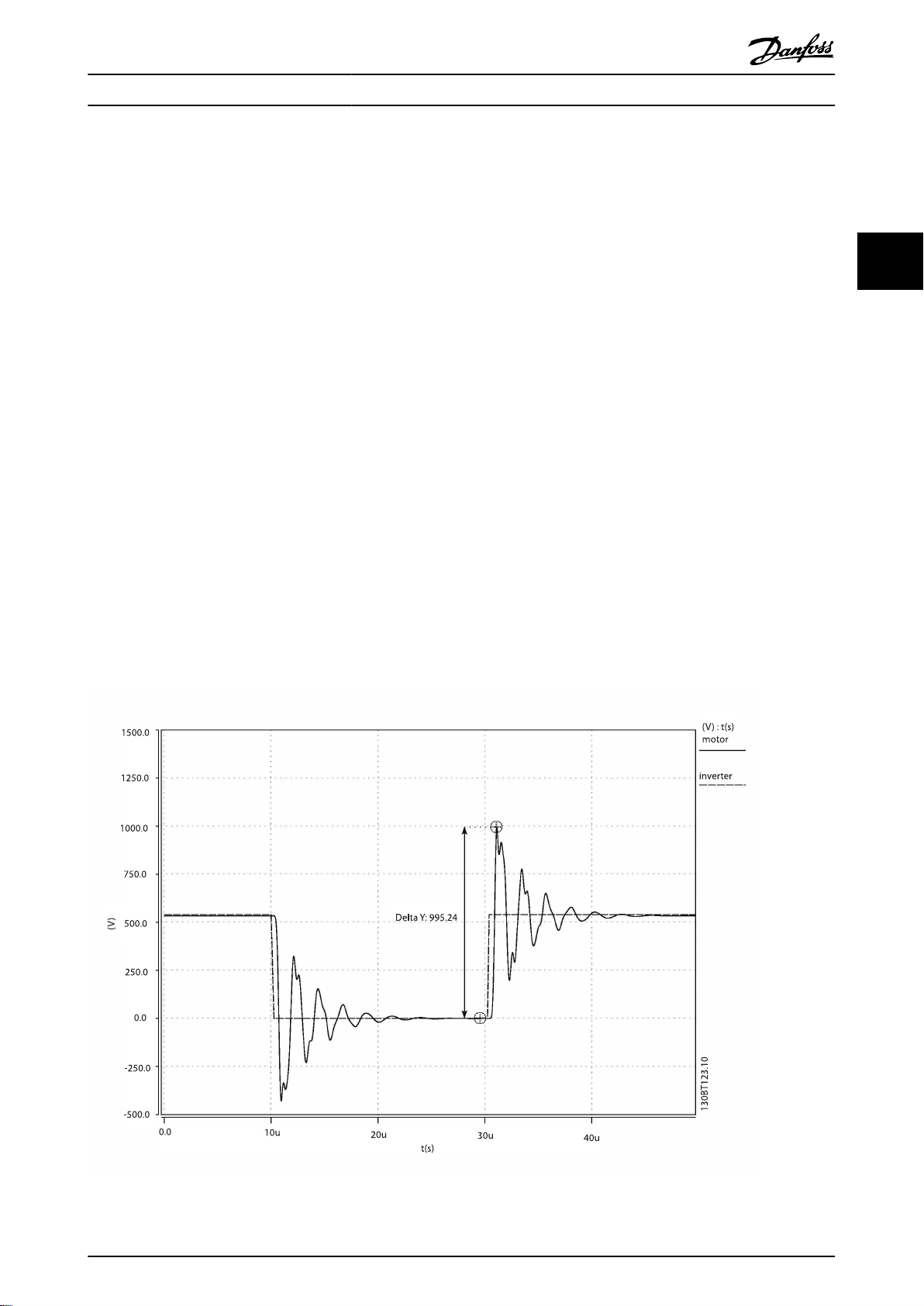
3.2.1 The Output Voltage
The output voltage of the frequency converter is a series of
trapezoidal pulses with a variable width (pulse width
modulation) characterized by a pulse rise-time tr.
When a transistor in the inverter switches, the voltage across
the motor terminal increases by a dU/dt ratio that depends
on:
the motor cable (type, cross-section, length,
•
screened or unscreened, inductance and
capacitance)
the high frequency surge impendance of the motor
•
Because of the impedance mismatch between the cable
characteristic impedance and the motor surge impedance a
wave reflection occurs, causing a ringing voltage overshoot
at the motor terminals - see Illustration 3.1. The motor surge
impedance decreases with the increase of motor size
resulting in reduced mismatch with the cable impedance.
The lower reflection coefficient (Γ) reduces the wave
reflection and thereby the voltage overshoot. Typical values
are given in Table 3.1.
In the case of parallel cables the cable characteristic
impedance is reduced, resulting in a higher reflection
coefficient higher overshoot. For more information please
see IEC 61800-8.
3
3
Illustration 3.1 Example of Converter Output Voltage (dotted line) and Motor Terminal Voltage After 200m of Cable (solid line)
MG.90.N5.02 - VLT® is a registered Danfoss trademark 5
Page 7
Introduction to Output Filt... Output Filters Design Guide
3
Typical values for the rise time and peak voltage U
PEAK
are
measured on the motor terminals between two phases.
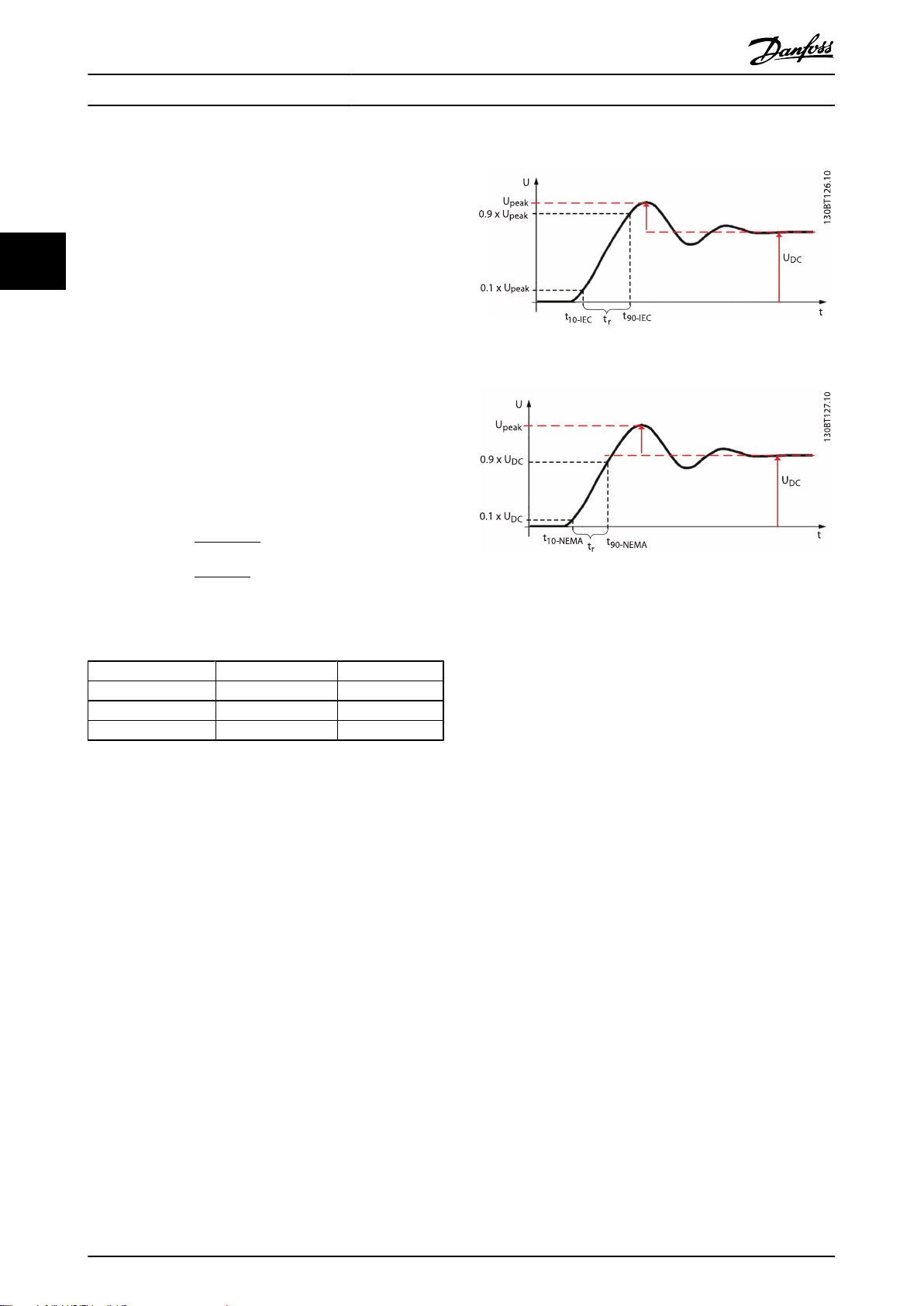
Two different definitions for the risetime tr are used in
practice. The international IEC standards define the rise-time
as the time between 10% to 90% of the peak voltage U
peak
The US National Electrical Manufacturers Association (NEMA)
defines the rise-time as the time between 10% and 90% of
the final, settled voltage, that is equal to the DC link voltage
UDC. See Illustration 3.2 and Illustration 3.3.
To obtain approximate values for cable lengths and voltages
not mentioned below, use the following rules of thumb:
1. Rise time increases with cable length.
2.
U
= DC link voltage x (1+Γ); Γ represents the
PEAK
reflection coefficient and typical values can be
found in table below
(DC link voltage = Mains voltage x 1.35).
0.8 ×
0.8 ×
t
(
NEMA
r
U
PEAK
(IEC)
t
r
U
DC
(NEMA)
)
values at different cable lengths
peak
3.
dU/dt =
dU/dt
=
(For dU/dt, rise time, U
please consult the drive Design Guide)
Motor power [kW]
<3.7 2000 - 5000 0.95
90 800 0.82
355 400 0.6
Table 3.1 Typical Values for Reflection Coefficients (IEC 61800-8).
Zm [Ω]
Γ
The IEC and NEMA Definitions of Risetime t
r
.
Illustration 3.2 IEC
Illustration 3.3 NEMA
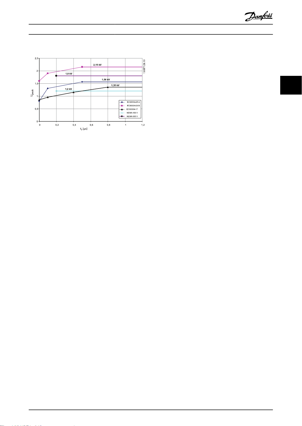
Various standards and technical specifications present limits
of the admissible U
and tr for different motor types. Some
peak
of the most used limit lines are shown in Illustration 3.4
IEC 60034-17 – limit line for general purpose
•
motors when fed by frequency converters, 500V
motors.
IEC 60034-25 – limit for converter rated motors:
•
curve A is for 500V motors and curve B is for 690V
motors.
NEMA MG1 – Definite purpose Inverter Fed Motors.
•
If, in your application, the resulting U
and tr exceed the
peak
limits that apply for the motor used, an output filter should
be used for protecting the motor insulation.
6 MG.90.N5.02 - VLT® is a registered Danfoss trademark
Page 8
Introduction to Output Filt... Output Filters Design Guide
3
3
Illustration 3.4 Limit Lines for U
and Risetime tr.
peak
3.3 Reduction of Motor Acoustic Noise
The acoustic noise generated by motors has three main
sources.
1. The magnetic noise produced by the motor core,
through magnetostriction
2. The noise produced by the motor bearings
3. The noise produced by the motor ventilation
When a motor is fed by a frequency converter, the
pulsewidth modulated (PWM) voltage applied to the motor
causes additional magnetic noise at the switching frequency
and harmonics of the switching frequency (mainly the
double of the switching frequency). In some applications this
is not acceptable. In order to eliminate this additional
switching noise, a sine-wave filter should be used. This will
filter the pulse shaped voltage from the frequency converter
and provide a sinusoidal phase-to-phase voltage at the
motor terminals.
MG.90.N5.02 - VLT® is a registered Danfoss trademark 7
Page 9
3
Introduction to Output Filt... Output Filters Design Guide
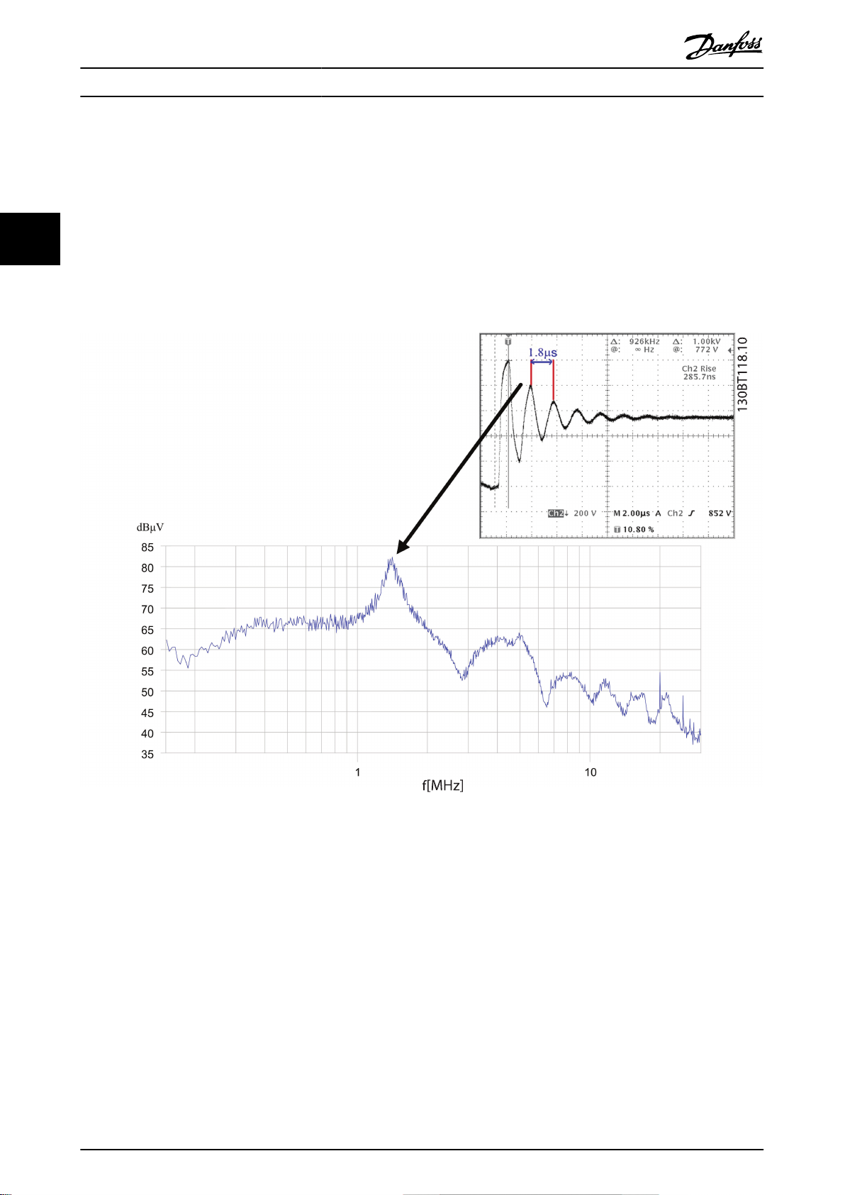
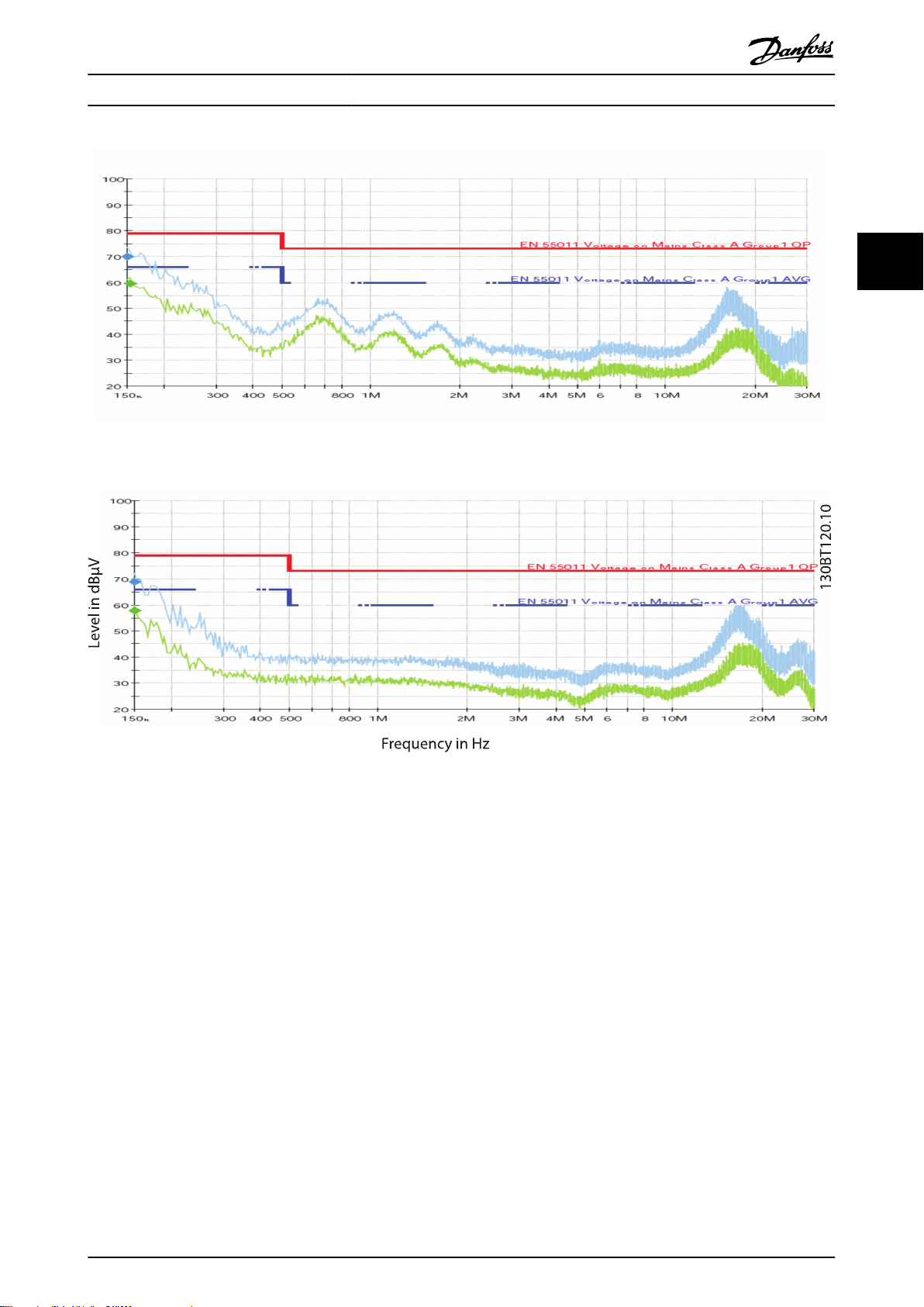
3.4 Reduction of High Frequency Electromagnetic Noise in the Motor Cable
When no filters are used, the ringing voltage overshoot that occurs at the motor terminals is the main high-frequency noise
source. Illustration 3.5 shows the correlation between the frequency of the voltage ringing at the motor terminals and the
spectrum of the high-frequency conducted interference in the motor cable.
Besides this noise component, there are also other noise components such as:
The common-mode voltage between phases and ground at the switching frequency and its harmonics - high
•
amplitude but low frequency.
High-frequency noise (above 10MHz) caused by the switching of semiconductors - high frequency but low amplitude.
•
Illustration 3.5 Correlation Between the Frequency of the Ringing Voltage Overshoot and the Spectrum of Noise Emissions.
When an output filter is installed following effect is achieved:
In the case of dU/dt filters the frequency of the ringing oscillation is reduced below 150kHz.
•
In the case of sine-wave filters the ringing oscillation is completely eliminated and the motor is fed by a sinusoidal
•
phase-to-phase voltage.
Remember, that the other two noise components are still present. This is illustrated in the conducted emission measurements
shown in Illustration 3.7 and Illustration 3.8. The use of unshielded motor cables is possible, but the layout of the installation
should prevent noise coupling between the unshielded motor cable and the mains line or other sensitive cables (sensors,
communication, etc.). This can be achieved by cable segregation and placement of the motor cable in a separate, continuous
and grounded cable tray.
8 MG.90.N5.02 - VLT® is a registered Danfoss trademark
Page 10

Introduction to Output Filt... Output Filters Design Guide
3.5 What are Bearing Currents and Shaft
Voltages?
Fast switching transistors in the frequency converter
combined with an inherent common-mode voltage (voltage
between phases and ground) generate high-frequency
bearing currents and shaft voltages. While bearing currents
and shaft voltages can also occur in direct-on-line motors,
these phenomena are accentuated when the motor is fed
from a frequency converter. The majority of bearing
damages in motors fed by frequency converters are because
of vibrations, misalignment, excessive axial or radial loading,
improper lubrication, impurities in the grease. In some cases,
bearing damages are caused by bearing currents and shaft
voltages. The mechanism that causes bearing currents and
shaft voltages is quite intricate and beyond the scope of this
Design Guide. Basically, two main mechanisms can be
identified:
Capacitive coupling: the voltage across the bearing
•
is generated by parasitic capacitances in the motor.
Inductive coupling: caused by circulating currents
•
in the motor.
The grease film of a running bearing behaves like isolation.
The voltage across the bearing can cause a breakdown of the
grease film and produce a small electric discharge (a spark)
between the bearing balls and the running track. This
discharge produces a microscopic melting of the bearing ball
and running track metal and in time it causes the premature
wear-out of the bearing. This mechanism is called Electrical
Discharge Machining or EDM.
Measures that isolate the motor shaft from the load
Use isolated bearings (or at least one isolated
•
bearing at the non-driving end NDE).
Prevent shaft ground current by using isolated
•
couplings.
Mechanical measures
Make sure that the motor and load are properly
•
aligned.
Make sure the loading of the bearing (axial and
•
radial) is within the specifications.
Check the vibration level in the bearing.
•
Check the grease in the bearing and make sure the
•
bearing is correctly lubricated for the given
operating conditions.
One of the mitigation measures is to use filters. This can be
used in combination with other measures, such as those
presented above. High-frequency common-mode (HF-CM)
filters (core kits) are specially designed for reducing bearing
stress. Sine-wave filters also have a good effect. dU/dt filters
have less effect and it is recommended to use them in
combination with HF-CM cores.
3
3
Mitigation of Premature Bearing Wear-
3.5.1
Out
There are a number of measures that can be taken for
preventing premature wearing and damage of the bearings
(not all of them are applicable in all cases – combinations
can be used). These measures aim either to provide a lowimpedance return path to the high-frequency currents or to
electrically isolate the motor shaft for preventing currents
through the bearings. Besides, there are also mechanical
related measures.
Measures to provide a low-impedance return path
Follow EMC installation rules strictly. A good high-
•
frequency return path should be provided between
motor and frequency converter, for example by
using shielded cables.
Make sure that the motor is properly grounded and
•
the grounding has a low-impedance for highfrequency currents.
Provide a good high-frequency ground connection
•
between motor chassis and load.
Use shaft grounding brushes.
•
MG.90.N5.02 - VLT® is a registered Danfoss trademark 9
Page 11
129
50 - 200
MHz
130BB729.10
130B8000
3
Introduction to Output Filt... Output Filters Design Guide
3.5.2 Measuring Electric Discharges in the
Motor Bearings
The occurrence of electric discharges in the motor bearings
can be measured using an oscilloscope and a brush to pick
up the shaft voltage. This method is difficult and the
interpretation of the measured waveforms requires a deep
understanding of the bearing current phenomena. An easy
alternative is to use an electrical discharge detector
(130B8000), as shown in Illustration 3.6. Such a device
consists of a loop antenna that receives signals in the
frequency range of 50MHz – 200MHz and a counter. Each
electric discharge produces an electromagnetic wave that is
detected by the instrument and the counter is incremented.
If the counter displays a high number of discharges it means
that there are many discharges occurring in the bearing and
mitigation measures have to be taken to prevent the early
wear out of the bearing. This instrument can be used for
experimentally determining the exact number of cores
needed to reduce bearing currents. Start with a set of 2
cores. If the discharges are not eliminated, or drastically
reduced, add more cores. The number of cores presented in
the table above is a guiding value that should cover most
applications with a generous safety margin. If the cores are
installed on the drive terminals and you experiment core
saturation because of long motor cables (the cores have no
effect on bearing currents), check the correctness of the
installation. If cores keep saturating after the installation is
made according to EMC best practice, consider moving the
cores to the motor terminals.
Illustration 3.6 Electrical Discharge Detector
10 MG.90.N5.02 - VLT® is a registered Danfoss trademark
Page 12
Level in dBµV
Frequency in Hz
130BT119.10
Introduction to Output Filt... Output Filters Design Guide
Illustration 3.7 Mains Line Conducted Noise, No Filter
3
3
Illustration 3.8 Mains Line Conducted Noise, Sine-wave Filter
MG.90.N5.02 - VLT® is a registered Danfoss trademark 11
Page 13
3
Introduction to Output Filt... Output Filters Design Guide
3.6 Which Filter for which Purpose
Table 3.2 shows a comparison of dU/dt, Sine-wave filter, and HF-CMperformance. It can be used to determine which filter to use
with your application.
Performance criteria dU/dt filters Sine-wave filters High-frequency common-mode filters
Motor insulation
stress
Motor bearing stress Slightly reduced, only in high-
EMC performance Eliminates motor cable ringing.
Max. motor cable
length
Acoustic motor
switching noise
Relative size 15-50% (depending on power size) 100% 5 - 15%
Voltage drop
Up to 150m cable (screened/
unscreened) complies with the
requirements of IEC 60034-17
(general purpose motors). Above
this cable length the risk of “double
pulsing” (two time mains network
voltage) increases.
power motors.
Does not change the emission class.
Does not allow longer motor cables
as specified for the frequency
converter’s built-in RFI filter.
100m ... 150m
With guaranteed EMC performance:
150m screened.
Without guaranteed EMC
performance: 150m unscreened.
Does not eliminate acoustic
switching noise.
0.5% 4-10% none
Provides a sinusoidal phase-to-phase
motor terminal voltage. Complies with
1
IEC 60034-17 1 and NEMA-MG1
requirements for general purpose
motors with cables up to 500m (1km for
VLT frame size D and above).
Reduces bearing currents caused by
circulating currents. Does not reduce
common-mode currents (shaft
currents).
Eliminates motor cable ringing. Does
not change the emission class. Does not
allow longer motor cables as specified
for the frequency converter’s built-in
RFI filter.
With guaranteed EMC performance:
150m screened and 300m unscreened.
Without guaranteed EMC performance:
up to 500m (1km for VLT frame size D
and above)
Eliminates acoustic switching noise
from the motor caused by magnetostriction.
Does not reduce motor insulation stress
Reduces bearing stress by limiting
common-mode high-frequency
currents
Reduces high-frequency emissions
(above 1MHz). Does not change the
emission class of the RFI filter. Does not
allow longer motor cables as specified
for the frequency converter.
150m screened (frame size A, B, C), 300
m screened (frame size D, E, F), 300 m
unscreened
Does not eliminate acoustic switching
noise.
Table 3.2 Comparison of dU/dt and Sine-wave Filters
1) Not 690V.
2) See general specification for formula.
3.6.1 dU/dt Filters
The dU/dt filters consist of inductors and capacitors in a low
pass filter arrangement and their cut off frequency is above
the nominal switching frequency of the frequency converter.
The inductance (L) and capacitance (C) values are shown in
the tables in 4.2 Electrical Data - dU/dt Filters. Compared to
Sine-wave filters they have lower L and C values, thus they
are cheaper and smaller. With a dU/dt filter the voltage wave
form is still pulse shaped but the current is sinusoidal - see
following illustrations.
Features and benefits
dU/dt filters reduce the voltage peaks and dU/dt of the
pulses at the motor terminals. The dU/dt filters reduce dU/dt
to approx. 500V/μs.
Advantages
Protects the motor against high dU/dt values and
•
voltage peaks, hence prolongs the lifetime of the
motor
Allows the use of motors which are not specifically
•
designed for converter operation, for example in
retrofit applications
Application areas
Danfoss recommends the use of dU/dt filters in the following
applications:
Applications with frequent regenerative braking
•
Motors that are not rated for frequency converter
•
operation and not complying with IEC 600034-25
Motors placed in aggressive environments or
•
running at high temperatures
Applications with risk of flash over
•
12 MG.90.N5.02 - VLT® is a registered Danfoss trademark
Page 14
130BB113.11
Upeak [kV]
15m dv/dt filter
rise time [µs]
150m dv/dt filter
50m dv/dt filter
Introduction to Output Filt... Output Filters Design Guide
Installations using old motors (retrofit) or general
•
purpose motors not complying with IEC 600034-17
Applications with short motor cables (less than
•
15m)
690V applications
•
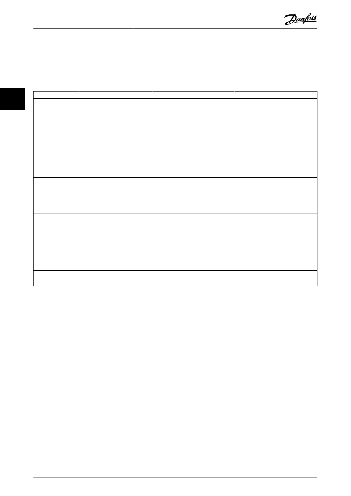
Voltage and current with and without dU/dt filter:
Illustration 3.11 Measured dU/dt values (rise time and peak
voltages) with and without dU/dt filter using 15m, 50m and 150m
cable lengths on a 400V, 37kW induction motor.
The dU/dt value decreases with the motor cable length
whereas the peak voltage increases (see Illustration 3.11). The
U
peak
and as Udc increases during motor braking (generative) U
can increase to values above the limits of IEC 60034-17 and
thereby stress the motor insulation. Danfoss therefore
Illustration 3.9 Without Filter
recommends dU/dt filters in applications with frequent
braking. Furthermore the illustration above shows how the
U
peak
increases, the cable capacitance rises and the cable behaves
like a low-pass filter. That means longer rise-time tr for longer
cables. Therefore it is recommended to use dU/dt filters only
in applications with cable lengths up to 150m. Above 150m
dU/dt filters have no effect. If further reduction is needed,
use a sine-wave filter.
value depends on the Udc from the frequency converter
peak
increases with the cable length. As the cable length
3
3
Illustration 3.10 With dU/dt Filter
Filter features
IP00 and IP20/23/54 enclosure in the entire power
•
range
Side by side mounting with the drive
•
Reduced size, weight and price compared to the
•
sine-wave filters
Possibility of connecting screened cables with
•
included decoupling plate
Compatible with all control principles including
•
flux and VVC
Filters wall mounted up to 177A and floor mounted
MG.90.N5.02 - VLT® is a registered Danfoss trademark 13
•
above that size
PLUS
Page 15
3
Introduction to Output Filt... Output Filters Design Guide
3.6.2
Sine-wave filters are designed to let only low frequencies
pass. High frequencies are consequently shunted away
which results in a sinusoidal phase to phase voltage
waveform and sinusoidal current waveforms. With the
sinusoidal waveforms the use of special frequency converter
motors with reinforced insulation is no longer needed. The
acoustic noise from the motor is also damped as a
consequence of the sinusoidal wave condition. The sinewave filter also reduces insulation stress and bearing
currents in the motor, thus leading to prolonged motor
lifetime and longer periods between services. Sine-wave
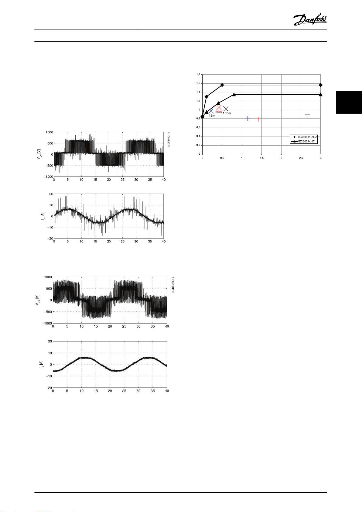
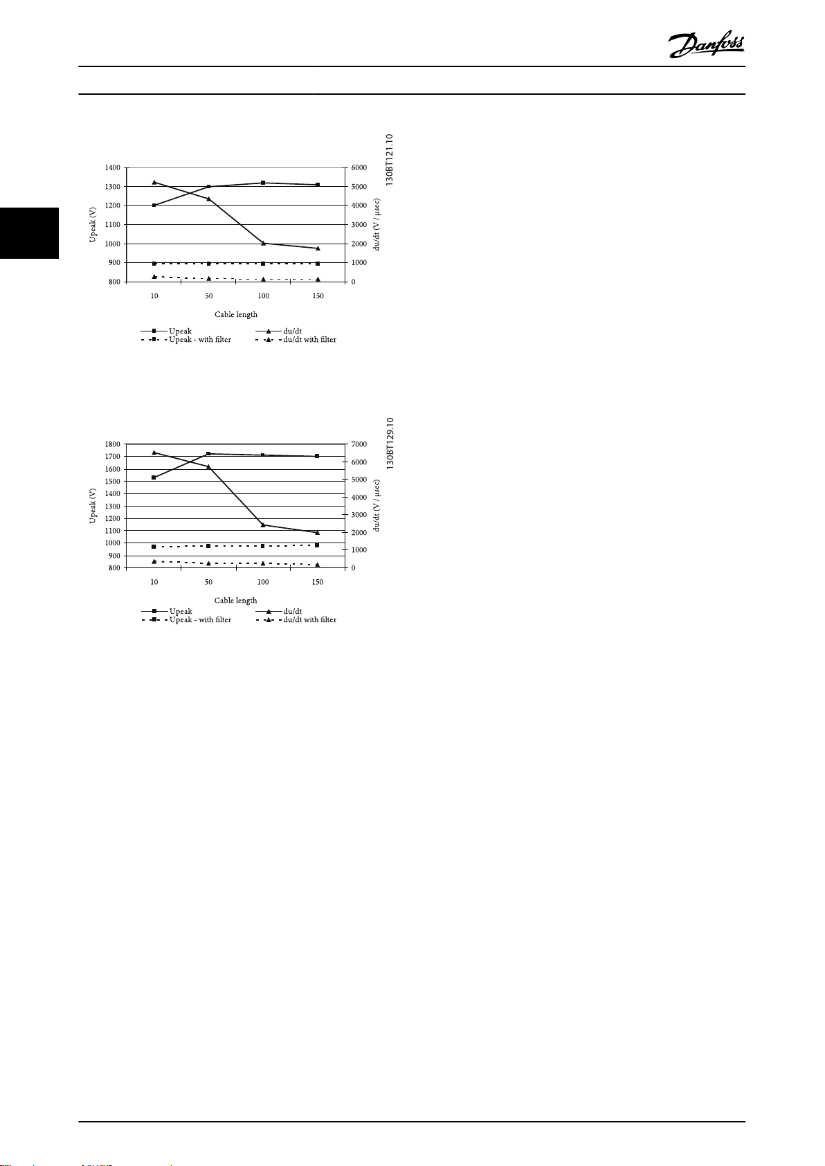
Illustration 3.12 525V - With and Without dU/dt Filter
filters enable use of longer motor cables in applications
where the motor is installed far from the frequency
converter. As the filter does not act between motor phases
and ground, it does not reduce leakage currents in the
cables. Therefore the motor cable length is limited - see
Table 3.2.
The Danfoss Sine-wave filters are designed to operate with
the VLT® FC 100/200/300. They replace the LC-filter product
range and are backwards compatible with the VLT
5000-8000 Series Drives. They consist of inductors and
capacitors in a low-pass filter arrangement. The inductance
(L) and capacitance (C) values are shown in tables in
4.3 Electrical Data - Sine-wave Filters.
Sine-wave Filters
Illustration 3.13 690V - With and Without dU/dt Filter
Source: Test of 690V 30kW VLT FC 302 with MCC 102 dU/dt
filter
Illustration 3.12 and Illustration 3.13 show how U
time behaves as a function of the motor cable length. In
installations with short motor cables (below 5-10m) the rise
time is short which causes high dU/dt values. The high dU/dt
can cause a damaging high potential difference between the
windings in the motor which can lead to breakdown of the
insulation and flash-over. Danfoss therefore recommends
dU/dt filters in applications with motor cable lengths shorter
than 15m.
peak
and rise
Features and benefits
As described above, Sine-wave filters reduce motor
insulation stress and eliminate switching acoustic noise from
the motor. The motor losses are reduced because the motor
is fed with a sinusoidal voltage, as shown in Illustration 3.12.
Moreover, the filter eliminates the pulse reflections in the
motor cable thus reducing the losses in the frequency
converter.
Advantages
Protects the motor against voltage peaks hence
•
prolongs the lifetime
Reduces the losses in the motor
•
Eliminates acoustic switching noise from the motor
•
Reduces semiconductor losses in the drive with
•
long motor cables
Decreases electromagnetic emissions from motor
•
cables by eliminating high frequency ringing in the
cable
Reduces electromagnetic interference from
•
unscreened motor cables
Reduces the bearing current thus prolonging the
•
lifetime of the motor
14 MG.90.N5.02 - VLT® is a registered Danfoss trademark
Page 16

Introduction to Output Filt... Output Filters Design Guide
Voltage and current with and without Sine-wave filter
Illustration 3.14 Without Filter
Applications with motor cables above 150m up to
•
300m (with both screened and unscreened cable).
The use of motor cables longer than 300m
depends on the specific application
Applications where the service interval on the
•
motor has to be increased
690V applications with general purpose motors
•
Step up applications or other applications where
•
the frequency converter feeds a transformer
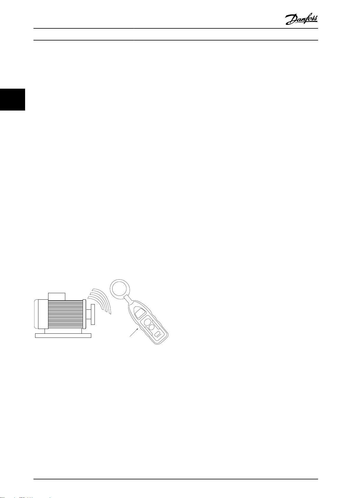
Example of relative motor sound pressure level
measurements with and without Sine-wave filter
3
3
Illustration 3.15 With Sine-wave Filter
Application areas
Danfoss recommends the use of Sine-wave filters in the
following applications.
Applications where the acoustic switching noise
•
from the motor has to be eliminated
Retrofit installations with old motors with poor
•
insulation
Applications with frequent regenerative braking
•
and motors that do not comply with IEC 60034-17
Applications where the motor is placed in
•
aggressive environments or running at high
temperatures
MG.90.N5.02 - VLT® is a registered Danfoss trademark 15
Features
•
•
•
•
•
•
IP00 and IP20 enclosure in the entire power range
(IP23 for floor standing filters)
Compatible with all control principle including flux
and VVC
Side by side mount with the frequency converter
up to 75A
Filter enclosure matching the frequency converter
enclosure
Possibility of connecting unscreened and screened
cables with included decoupling plate
Filters wall mounted up to 75A and floor mount
above
PLUS
Page 17

Introduction to Output Filt... Output Filters Design Guide
Parallel filter installation is possible with
•
applications in the high power range
3.6.3 High-Frequency Common-Mode Core
Kits
3
High-frequency common-mode (HF-CM) core kits are one of
the mitigation measures to reduce bearing wear. However,
they should not be used as the sole mitigation measure.
Even when HF-CM cores are used, the EMC-correct installation rules must be followed. The HF-CM cores work by
reducing the high-frequency common-mode currents that
are associated with the electric discharges in the bearing.
They also reduce the high-frequency emissions from the
motor cable which can be used, for example, in applications
with unshielded motor cables.
16 MG.90.N5.02 - VLT® is a registered Danfoss trademark
Page 18

Selection of Output Filters Output Filters Design Guide
4 Selection of Output Filters
4.1 How to Select the Correct Output Filter
An output filter is selected based on the nominal motor current. All filters are rated for 160% overload for 1 minute, every 10
minutes.
4.1.1 Product Overview
To simplify the Filter Selection Table 4.1 shows which Sine-wave filter to use with a specific frequency converter. This is based on
the 160% overload for 1 minute every 10 minutes and is to be considered guideline.
Mains supply 3 x 240 to 500V
Rated filter
current at 50Hz
2.5 5 120 130B2439 130B2404 PK25 - PK37 PK37 - PK75 PK37 - PK75
4.5 5 120 130B2441 130B2406 PK55 P1K1 - P1K5 P1K1 - P1K5
8 5 120 130B2443 130B2408 PK75 - P1K5 P2K2 - P3K0 P2K2 - P3K0
10 5 120 130B2444 130B2409 P4K0 P4K0
17 5 120 130B2446 130B2411 P2K2 - P4K0 P5K5 - P7K5 P5K5 - P7K5
24 4 100 130B2447 130B2412 P5K5 P11K P11K
38 4 100 130B2448 130B2413 P7K5 P15K - P18K P15K - P18K
48 4 100 130B2307 130B2281 P11K P22K P22K
62 3 100 130B2308 130B2282 P15K P30K P30K
75 3 100 130B2309 130B2283 P18K P37K P37K
115 3 100 130B3181 130B3179 P22K - P30K P45K - P55K P55K - P75K
180 3 100 130B3183 130B3182 P37K - P45K P75K - P90K P90K - P110
260 3 100 130B3185 130B3184 P110 - P132 P132
410 3 100 130B3187 130B3186 P160 - P200 P160 - P200
510 3 100 130B3189 130B3188 P250 P250
660 2 70 130B3192 130B3191 P315 - P355 P315 - P355
800 2 70 130B3194 130B3193 P400 P400 - P450
1020 2 70 2 x 130B3189 2 x 130B3188 P450 - P500 P500 - P560
1320 2 70 2 x 130B3192 2 x 130B3191 P560 - P630 P630 - P710
1530 2 70 3 x 130B3189 3 x 130B3188 P710 - P800 P800
1980 2 70 3 x 130B9192 3 x 130B3191 P1M0
Minimum
switching
frequency [kHz]
Maximum output
frequency [Hz] With
derating
Code number
IP20
Code number
IP00
Frequency converter size
200-240V 380-440V 441-500V
4 4
Table 4.1 Filter Selection
MG.90.N5.02 - VLT® is a registered Danfoss trademark 17
Page 19

Selection of Output Filters Output Filters Design Guide
Mains supply 3 x 525 to 600/690V
Rated filter
current at 50Hz
13 2 70 130B3196 130B3195 PK75 - P7K5
28 2 100 130B4113 130B4112 P11K - P18K
45 2 100 130B4115 130B4114 P22K - P30K P37K
76 2 100 130B4117 130B4116 P37K - P45K P45K - P55K
44
115 2 100 130B4119 130B4118 P55K - P75K P75K - P90K
165 2 70 130B4124 130B4121 P110 - P132
260 2 100 130B4126 130B4125 P160 - P200
303 2 70 130B4151 130B4129 P250
430 1.5 60 130B4153 130B4152 P315 - P400
530 1.5 100 130B4155 130B4154 P500
660 1.5 100 130B4157 130B4156 P560 - P630
868 1.5 60 2 x 130B4153 2 x 130B4152 P710
1060 1.5 100 2 x 130B4155 2 x 130B4154 P800 - P900
1590 1.5 60 3 x 130B4155 3 x 130B4154 P1M0
Table 4.2 Filter Selection
Minimum
switching
frequency [kHz]
Maximum output
frequency [Hz] With
derating
Code number
IP20
Code number
IP00
Frequency converter size
525-600V 525-690V
Generally the output filters are designed for the nominal
switching frequency of the frequency converter.
NOTE
Sine-wave filters can be used at switching frequencies higher
than the nominal switching frequency, but should never be
used at switching frequencies with less than 20% lower than
the nominal switching frequency.
NOTE
dU/dt filters, unlike Sine-wave filters, can be used at lower
switching frequency than the nominal switching frequency,
but higher switching frequency will cause the overheating of
the filter and should be avoided.
18 MG.90.N5.02 - VLT® is a registered Danfoss trademark
Page 20

W
w
H
h
d
130BB728.10
Selection of Output Filters Output Filters Design Guide
4.1.2 HF-CM Selection
The cores can be installed at the frequency converter’s
output terminals (U, V, W) or in the motor terminal box.
When installed at the frequency converter’s terminals the
HF-CM kit reduces both bearing stress and high-frequency
electromagnetic interference from the motor cable. The
number of cores depends on the motor cable length and
frequency converter voltage and a selection table is shown
below.
Cable
length
[m]
100 4 4 2 4 4 4 2 4
150 4 6 4 4 4 4 4 4
300 4 6 4 4 4 6 4 4
When installed in the motor terminal box the HF-CM kit
reduces only bearing stress and has no effect on the electromagnetic interference from the motor cable. Two cores are
sufficient in most cases, independent of the motor cable
length.
Danfoss provides the HF-CM cores in kits of two pieces/kit.
The cores are oval shaped for the ease of installation and are
available in four sizes: for A and B frames, for C frames, for D
frames, for E and F frames. For F frame frequency converters,
one core kit shall be installed at each inverter module
terminals. Mechanical mounting can be made with cable ties.
There are no special requirements regarding mechanical
mounting.
A- and B
frame
T5 T7 T5 T7 T5 T7 T5 T7
50 2 4 2 2 2 4 2 2
C frame D frame E- F frame
CAUTION
Check the core temperature during commissioning. A
temperature above 70°C indicates saturation of the cores. If
this happens add more cores. If the cores still saturate it
means that the cable capacitance is too large because of: too
long cable, too many parallel cables, cable type with high
capacitance.
Applications with parallel cables
When parallel cables are used the total cable length has to
be considered. For example 2 x 100m cables are equivalent
with one 200m cable. If many paralleled motors are used a
separate core kit should be installed for each individual
motor.
The ordering numbers for the core kits (2 cores/package) are
given in the following table.
VLT
frame
size
A and B 130B3257 60 43 40 25 22 0.25 130x100x70
C 130B3258 102 69 61 28 37 1.6 190x100x70
D 130B3259 189 143 126 80 37 2.45 235x190x
E and F 130B3260 305 249 147 95 37 4.55 290x260x
Danfoss
part no.
Core dimension [mm] Weight Packaging
dimension
W w H h d [kg] [mm]
140
110
4 4
In normal operation the temperature is below 70°C.
However, if the cores are saturated they can get hot, with
temperatures above 70°C. Therefore it is important to use
the correct number of cores to avoid saturation. Saturation
can occur if the motor cable is too long, motor cables are
paralleled or high capacitance motor cables, not suitable for
frequency converter operation, are used. Always avoid motor
cables with sector-shaped cores. Use only cables with roundshaped cores.
MG.90.N5.02 - VLT® is a registered Danfoss trademark 19
Page 21

Selection of Output Filters Output Filters Design Guide
4.2 Electrical Data - dU/dt Filters
C
Filter
data
μH
44
filter losses
525 - 550V 551 - 690V
75 83
315 429 400 410
500V
380 - 440V 441 -
VLT power and current rating Maximum
200 -
690V
240v
@ 50HzkW
5.5 24.2 11 24 11 21 7.5 14 11 13 37 150 10
7.5 30.8 15 32 15 27 11 19 15 18
18.5 37.5 18.5 34 15 23 18.5 22
22 44 22 40 18.5 28 22 27
11 46.2 30 61 30 52 30 43 30 34 130 110 13.6
15 59.4 37 73 37 65 37 54 37 41
18.5 74.8 45 90 55 80 45 65 45 52
55 106 75 105 55 87 55 62 145 95 15
22 88
30 115 75 147 90 130 75 113 90 108 205 111 15
110 212 132 190 110 162 110 131 315 50 20
132 260 160 240 132 201 132 155
160 315 200 303 160 192
37 143 90 177 110 160 90 137
45 170
200 395 250 361 160 253 200 242 398 30 43
250 480 315 443 200 303 250 290
315 600 355 540 250 360 315 344 550 17 66
355 658 400 590 300 395 355 380
400 745 450 678 400 523 500 500 850 13 99
450 800 500 730 450 596 560 570
500 880 560 780 500 659 630 630
575/600V
@ 60Hz
3)
460/480V @
60Hz and
500/525V @
50Hz
2)
[A]
Filter current rating at given voltage and motor frequency
Code number IP00
20 MG.90.N5.02 - VLT® is a registered Danfoss trademark
1)
4
IP20/IP23
IP54
380V @ 60Hz
and
200/440V @
kW A kW A kW A kW A kW A W uH nF
50Hz
44 40 32 27
IP00
IP20
IP54
130B2835
130B2836
130B2837
90 80 58 54
IP00
IP20
IP54
130B2838
130B2839
130B2840
106 105 94 86
IP00
IP20
IP54
130B2841
130B2842
130B2843
177 160 131 108
IP00
IP20
IP54
130B2844
130B2845
130B2846
315 303 242 192
IP00
IP23
130B2847
130B2848
480 443 344 290
IP00
IP23
130B2849
130B2850
IP00
130B2851
658 590 500 450
IP23
130B2852
880 780 630 630
IP00
IP23
130B2853
130B2854
The filter enclosure is IP20 for wall-mounted filters and IP23 for floor-mounted filters2) For derating with motor frequency consider 60Hz rating=0.94 x 50Hz rating and 100Hz rating= 0.75 x 50Hz rating3) 525V operation requires a T7 drive
1)
Table 4.3 dU/dt Filter 3x200-690V IP00/IP20/IP23/IP54
IP54 is available up to 177A
4
Page 22

Selection of Output Filters Output Filters Design Guide
nF
Filter
data
μH
filter losses
VLT power and current size Maximum
380 - 440V 441 - 500V 525 - 550V 551 - 690V L C
690V
kW A kW A kW A kW A W
@ 50Hz
4 4
900 945
710 1260 800 1160 750 988or
575/600V
460/480V @
2
[A]
Filter current rating at given voltage and motor frequency
1
IP20/IP23
Code number IP00
380V @
@ 60Hz
60Hz and
60Hz and
500/525V @
200/440V @
3
50Hz
50Hz
For F frame drives, parallel filters shall be used, one filter for each
IP00
IP23
2 x 1302852
2 x 130B2851
inverter module.
IP00
IP23
3 x 130B2849
3 x 130B3850
IP00
IP23
or
2 x 130B2853
2 x 130B2854
IP00
IP23
IP00 800 1460 1000 1380 850 1108 1000 1060
3 x 130B2851
3 x 130B2852
3 x 130B2853
IP23 1000 1700 1100 1530 1000 1317 1200 1260
IP00 450 800 500 730 500 659
IP23 500 880 560 780
3 x 130B2854
2 x 130B2849
2 x 130B2852
The filter enclosure is IP20 for wall-mounted filters and IP23 for floor-mounted filters2) For derating with motor frequency consider 60Hz rating=0.94 x 50Hz rating and 100Hz rating= 0.75 x 50Hz rating3) 525V operation requires a T7 drive
1)
MG.90.N5.02 - VLT® is a registered Danfoss trademark 21
Page 23

Selection of Output Filters Output Filters Design Guide
4.3 Electrical Data - Sine-wave Filters
1
μF
-Value
y
C
29 10.25 1.8 0.55 1.8 0.55 1.6 50 50 50
L-value
13 2.2
6.9 4.71.1 6.6 2.2 5.6 2.2 4.8 75 70 70
3.1 103 12.5 5.5 13 5.5 11 100 110 100
1.6 10
44
470 0.51 15
650 0.33 25
850 0.34 25
VLT Power and Current Ratings Filter Losses
Switching
Frequency
@ 100Hz @ 200-240V @ 380-440V @ 441-500V @ 200-240V @ 380-440V @ 441-500V
@
Filter Current Rating
@ 50Hz
IP00
IP20
Code
60Hz
A A A kHz kW A kW A kW A W W W mH
2
(IP23)
Number
0.37 1.3 0.37 1.1 45 45
2.5 2.5 2* 5
IP00
IP20
130B2404
130B2439
1.1 3 1.1 3 60 60
0.37 2.4 0.75 2.4 0.75 2.1 60 60 60
IP00
130B2406
0.55 3.5 1.5 4.1 1.5 3.4 65 70 65
0.75 4.6 65
4.5 4 3.5* 5
IP20
130B2441
1.5 7.5 3 7.2 3 6.3 80 80 80
8 7.5 5* 5
IP00
IP20
130B2408
130B2443
2.2 10.6 90
10 9.5 7.5* 5 4 10 4 8.2 95 90 5.2 6.8
IP00
IP20
130B2409
130B2444
3.7 16.7 7.5 16 7.5 14.5 125 125 115
17 156 13 5
IP00
IP20
130B2411
130B2446
15 32 15 27 170 160
24 23 18 4 5.5 24.2 11 24 11 21 150 150 150 2.4 10
IP00
IP20
IP00
130B2412
130B2447
130B2413
7.5 30.8 18.5 37.5 18.5 34 160 180 170
38 36 28.5 4
IP20
IP00
130B2448
130B2281
48 45.5 36 4 11 46.2 22 44 22 40 270 270 260 1.1 14.7
IP20
IP00
130B2307
130B2282
62 59 46.5 3 15 59.4 30 61 30 52 300 310 280 0.85 30
IP20
IP00
130B2308
130B2283
22 88 45 90 55 80
75 71 56 3 18.5 74.8 37 73 37 65 350 350 330 0.75 30
IP20
IP00
130B2309
130B3179
30 115 55 106 75 105
37 143 75 147 90 130
115 109 86 3
IP23
IP00
130B3181
130B3182
110 212 132 190
45 170 90 177 110 160
180 170 135 3
IP23
IP00
130B3183
130B3184
132 260 160 240
260 246 195 3
IP23
130B3185
*) 120Hz
Equivalent STAR-connection value2IP23 - All floor mounted filters
1
Table 4.4 Sine-wave Filter 3x380-500 V IP00/IP20/IP23
22 MG.90.N5.02 - VLT® is a registered Danfoss trademark
Page 24

Selection of Output Filters Output Filters Design Guide
1
μF
-Value
y
C
L-value
4 4
VLT Power and Current Ratings Filter Losses
160 315 200 303
1150 0.25 33
200 395 250 361
315 600 355 540
2000 0.15 106
355 658 400 590
450 800 500 730
2900
500 880 560 780
560 990 630 890
4000
630 1120 710 1050
4350
710 1260 800 1160
800 1460 1000 1380
Switching
Frequency
@ 100Hz @ 200-240V @ 380-440V @ 441-500V @ 200-240V @ 380-440V @ 441-500V
@
@
Filter Current Rating
IP00
IP20
Code
60Hz
A A A kHz kW A kW A kW A W W W mH
50Hz
2
(IP23)
Number
410 390 308 3
IP00
IP23
IP00
130B3186
130B3187
130B3188
510 456 360 3 250 480 315 443 1450 0.14 66
IP23
IP00
130B3189
130B3191
660 627 495 3
800 712 562 2 400 745 450 678 3000 0.1 153
1020 912 720 2
1320 1254 990 2
1530 1368 1080 2
1980 1881 1485 2 1000 1700 1100 1530 6000
IP23
IP00
IP23
IP00
IP23
IP00
IP23
IP00
IP23
IP00
IP23
130B3192
130B3193
130B3194
2 x 130B3188
2 x 130B3189
2 x 130B3191
2 x 130B3192
3 x 130B3188
3 x 130B3189
3 x 130B3191
MG.90.N5.02 - VLT® is a registered Danfoss trademark 23
Equivalent STAR-connection value2IP23 - All floor mounted filters
3 x 130B3192
*) 120Hz
1
Table 4.5 Sine-wave Filter 3x380-500V IP00/IP20/IP23
Page 25

Selection of Output Filters Output Filters Design Guide
1
-
y
C
Value
L-value
μF
44
VLT Power and Current Ratings Filter losses
@ 525-550V @ 525-600V @ 690V @ 525-550V @ 525-600V @ 690V
0.75 1.7
1.1 2.4
1.5 2.7
2.2 4.1
115 8.1 4.7
3 5.2
4 6.4
5.5 9.5
7.5 11.5
11 13
11 18 15 18
150 5 10
15 22 18.5 22
18.5 27 22 27
22 34 30 34
250 2.5 15
30 41 30 46 37 46
37 52 37 56 45 54
475 1.6 33
45 62 45 76 55 73
55 83 55 90 75 86
750 0.91 33
75 100 75 113 90 108
90 131 90 137 110 131
1100 0.765 66
110 155 110 162 132 155
150 192 132 201 160 192
1300 0.48 66
180 242 160 253 200 242
220 290 200 303 250 290
1800 0.42 66
260 344 315 344 250 360
450 596 560 570
3000 0.19 153
480 630 630 630 500 596
Switching
Frequency
@
100Hz
@
60Hz
@ 50Hz
2
IP00
Code
A A A kHz kW A kW A kW A W W W mH
IP20(IP23)
Number
Filter Current Rating
24 MG.90.N5.02 - VLT® is a registered Danfoss trademark
13 12 9 2
IP00
IP20
130B3195
130B3196
28 26 21 2
IP00
IP23
130B4112
130B4113
45 42 33 2
IP00
IP23
IP00
130B4114
130B4115
130B4116
76 72 57 2
IP23
IP00
130B4117
130B4118
115 109 86 2
IP23
IP00
130B4119
130B4121
165 156 124 2
IP23
IP00
130B4124
130B4125
260 246 195 2
IP23
130B4126
360 314 270 2
IP00
IP23
IP00
130B4129
130B4151
130B4152
430 407 323 1.5 300 429 400 410 315 429 2150 0.285 99
IP23
IP00
130B4153
130B4154
530 502 398 1.5 375 523 500 500 400 523 2400 0.215 120
IP23
IP00
130B4155
130B4156
660 625 496 1.5
IP23
130B4157
1
Equivalent STAR-connection value2IP23 - All floor mounted filters
Table 4.6 Sine-wave Filter 3x525-690V IP00/IP20/IP23
Page 26
Selection of Output Filters Output Filters Design Guide
1
μF
-Value
y
C
4300
4800
7200
4 4
Filter Current Rating Switching Frequency VLT Power and Current Ratings Filter losses L-value
@ 50Hz @ 60Hz @ 100Hz @ 525-550V @ 525-600V @ 690V @ 525-550V @ 525-600V @ 690V
2
IP00
IP20(IP23)
A A A kHz kW A kW A kW A W W W mH
970 1260 1200 1260 1000 1317
860 814 646 1.5
IP23
670 898 800 850 630 763
1060 1004 796 1.5
IP23
820 1060 1000 1060 800 1108
1590 1506 1194 1.5
IP23
Code
Number
2 x 130B4142 IP00
2 x 130B4153 560 730 710 730 460 630
2 x 130B4154 IP00
3 x 130B4154 IP00
3 x 130B4155 970 1260 1200 1260 1000 1317
Equivalent STAR-connection value2IP23 - All floor mounted filters
1
MG.90.N5.02 - VLT® is a registered Danfoss trademark 25
2 x 130B4155 900 945 710 939
Page 27

Selection of Output Filters Output Filters Design Guide
1
μF
-Value
y
C
44
VLT Power and Current Rating Filter losses L-value
Frequency
Filter Current Rating Switching
A A A kHz kW A kW A kW A W W W mH
@ 50Hz @ 60Hz @ 100Hz @ 200-240V @ 380-440V @ 441-500V @ 200-240V @ 380-440V @ 441-500V
Code
Number
130B2542 10 10 8 5 2.2 10.6 4 10 4 8.2 60 60 5.3 1.36
3 12.5 5.5 13 5.5 11 100 100 100 3.1 2.04
130B2543 17 17 13.6 5
3.7 16.7 7.5 16 7.5 14.5 100 100 100 3.1 2.04
Table 4.7 Sine-wave Foot Print Filter 3x200-500V IP20
26 MG.90.N5.02 - VLT® is a registered Danfoss trademark
Page 28

130BB880.10
Selection of Output Filters Output Filters Design Guide
4.3.1 Spare Parts/Accessories
Protective earth (PE) grounding plate for IP00 and IP20 wall
mounted filters. The accessory bag also includes all
necessary screws and cable fixations.
Wall mounted Sine-wave filters
IP00 IP20
130B2404 130B2439
130B2406 130B2441
130B2408 130B2443
130B2409 130B2444
130B2411 130B2446
130B2412 130B2447
130B2413 130B2448
130B2341 130B2321
130B2281 130B2307
130B2282 130B2308
130B2283 130B2309
130B2835 130B2836 130B4175
130B2838 130B2839 130B4176
130B2841 130B2842 130B4177
Nom. filter current rating
(200-380/460/600/690V)
[A]
44/40/32/27 130B2835
90/80/58/54 130B2838
106/105/94/86 130B2841
177/160/131/108 130B2844
Filter code number Accessory bag
130B2836
130B2839
130B2842
130B2845
Accessories - L-shapes
Accessory bag
130B0385
130B0386
130B0387
130B4175
130B4176
130B4176
130B4127
Danfoss part
Voltage Current IP
13 00 130B3195 --13 20 130B3196 --28 00 130B4112 --28 20 130B4113 --45 00 130B4114 --45 20 130B4115 --76 00 130B4116 ---
76 23 130B4117 --115 00 130B4118 --115 23 130B4119 ---
690
165 00 130B4121 130B3137
165 23 130B4124 130B3137
260 00 130B4125 130B3137
260 23 130B4126 130B3137
360 00 130B4129 130B3138
360 23 130B4151 130B3138
430 00 130B4152 130B3138
430 23 130B4153 130B3138
530 00 130B4154 130B3138
530 23 130B4155 130B3138
660 00 130B4156 130B3139
660 23 130B4157 130B3139
no. L-shape
4.3.2 Cable Glands for Floor Standing Filters
Nom. filter current rating
(200-380/460/600/690V)
[A]
315/303/242/192 130B2848
480/443/344/290 130B2850
658/590/500/450 130B2852
880/780/630/630 130B2854
Filter code number Spare part no.
130B4178
4 4
Voltage Current IP
115 00 130B3179 --115 23 130B3181 --180 00 130B3182 --180 23 130B3183 --260 00 130B3184 130B3137
260 23 130B3185 130B3137
500
410 00 130B3186 130B3138
410 23 130B3187 130B3138
510 00 130B3188 130B3138
510 23 130B3189 130B3138
660 00 130B3191 130B3139
660 23 130B3192 130B3139
800 00 130B3193 130B3139
800 23 130B3194 130B3139
Danfoss part
no. L-shape
MG.90.N5.02 - VLT® is a registered Danfoss trademark 27
Page 29

Selection of Output Filters Output Filters Design Guide
4.3.3 Terminal Kits
Danfoss
Voltage Current IP
115 00 130B3179 115 23 130B3181 130B4178
180 00 130B3182 180 23 130B3183 130B4178
44
500
690
260 00 130B3184 260 23 130B3185 130B4178
410 00 130B3186 410 23 130B3187 130B4178
510 00 130B3188 510 23 130B3189 130B4178
660 00 130B3191 660 23 130B3192 130B4178
800 00 130B3193 800 23 130B3194 130B4178
13 00 130B3195 130B4175
13 20 130B3196 130B4175
28 00 130B4112 130B4175
28 20 130B4113 130B4175
45 00 130B4114 130B4176
45 20 130B4115 130B4176
76 00 130B4116 -
76 23 130B4117 130B4178
115 00 130B4118 115 23 130B4119 130B4178
165 00 130B4121 165 23 130B4124 130B4178
260 00 130B4125 260 23 130B4126 130B4178
360 00 130B4129 360 23 130B4151 130B4178
430 00 130B4152 430 23 130B4153 130B4178
530 00 130B4154 530 23 130B4155 130B4178
660 00 130B4156 660 23 130B4157 130B4178
part no. Spare parts
28 MG.90.N5.02 - VLT® is a registered Danfoss trademark
Page 30
97
98
99
130BB109.11
T emper a tur e der a ting cur v e lout[%]
110%
100%
90%
80%
70%
60%
45 46 47 48 49 50 51 52 53 54 55 56 57 58 59 60
Ambien t t emper a tur e [ º C]
cur r en t der a ting
130BB068.11
Selection of Output Filters Output Filters Design Guide
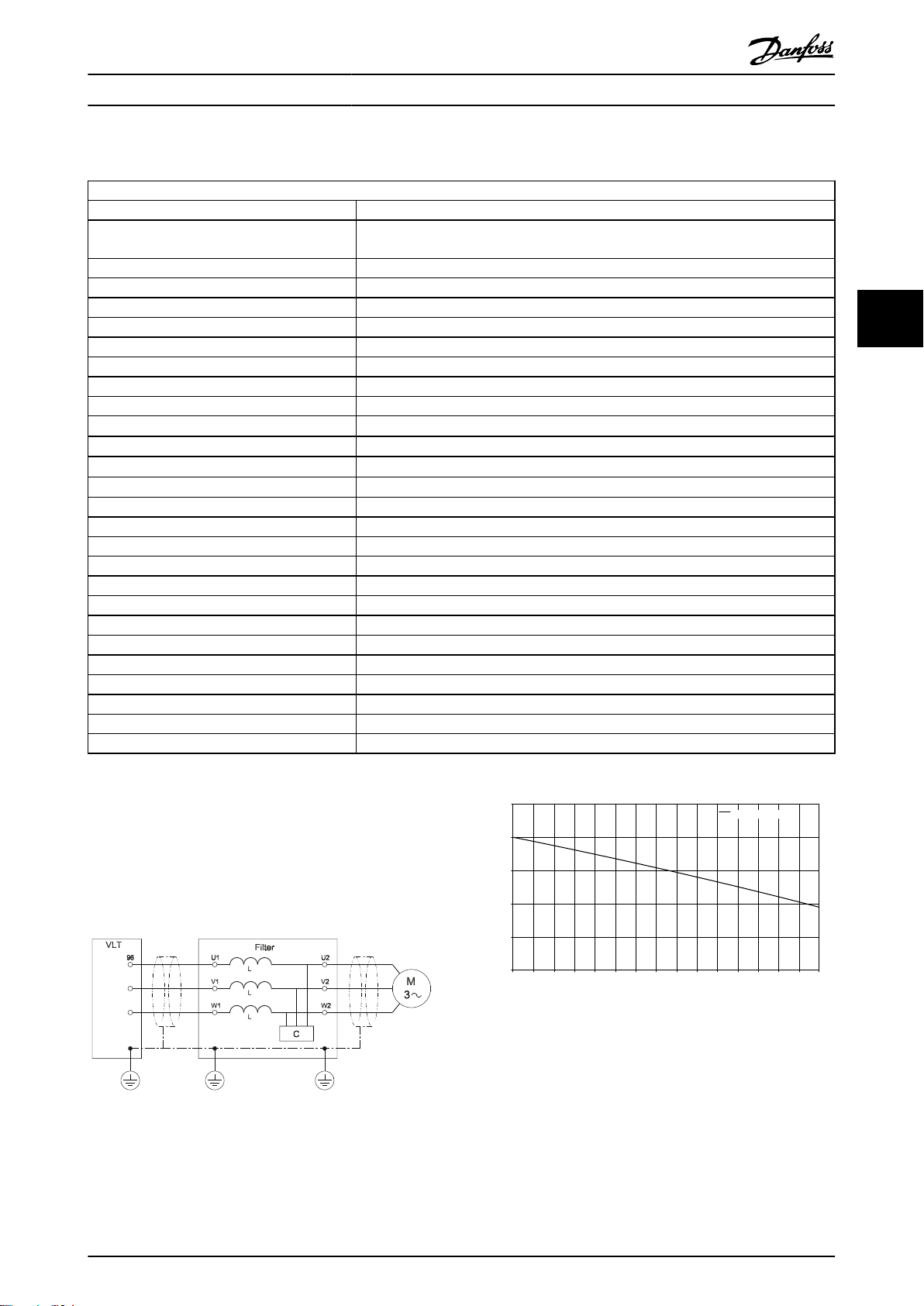
4.4 Sine-Wave Filters
Technical Specifications
Voltage rating 3 x 200-500V and 500-690V AC
up to 800A (500V) and 660A (690V). F frame current ratings are achieved by filter
Nominal current @ 50Hz
Motor frequency derating
50Hz Inominal
60Hz 0.94 x Inominal
100Hz 0.75 x Inominal
Minimum switching frequency nominal switching frequency of the respective FC 102, 202 or 302 x 0.80
Maximum switching frequency 8kHz
Overload capacity 160% for 60 seconds, every 10 minutes.
Enclosure degree IP00, IP20 for wall-mounted, IP23 for floor mounted.
Ambient temperature -10° to +45°C
Storage temperature -25° to +60°C
Transport temperature -25° to +70°C
Maximum ambient temperature (with derating) 55°C
Maximum altitude without derating 1000m
Maximum altitude with derating 4000m
Derating with altitude 5%/1000m
MTBF 1481842 h
FIT 1.5 106/h
Tolerance of the inductance
Degree of pollution EN 61800-5-1 II
Overvoltage category EN 61800-5-1 III
Environmental Conditions Load 3K3
Environmental Conditions Storage 1K3
Environmental Conditions Transport 2K3
Noise level < frequency converter
Approvals CE (EN 61558, VDE 0570), RoHS, cULus file E219022 (pending)
paralleling, one filter per inverter module.
± 10%
4 4
The voltage drop across the inductor can be calculated using
this formula:
ud
= 2 × π ×
f
× L ×
m
I
fm = output frequency
L = filter inductions
I = current
Illustration 4.1 Filter Diagram
MG.90.N5.02 - VLT® is a registered Danfoss trademark 29
Page 31

Selection of Output Filters Output Filters Design Guide
4.4.1 dU/dt Filters
Technical Specifications
Voltage rating 3 x 200-690V
Nominal current @ 50Hz up to 880A. F frame current ratings are achieved by filter paralleling, one filter per inverter module.
Motor frequency derating
50Hz Inominal
60Hz 0.94 x Inominal
44
Minimum switching frequency no limit
Maximum switching frequency nominal switching frequency of the respective FC 102, 202 or 302
Overload capacity 160% for 60 seconds, every 10 minutes.
Enclosure degree IP00, IP 20 for wall-mounted, IP23 for floor mounted. IP21/NEMA 1 available for wall-mounted using
Ambient temperature
Storage temperature
Transport temperature
Maximum ambient temperature (with
derating) Maximum altitude without
derating
Maximum altitude without derating 1000m
Maximum altitude with derating 4000m
Derating with altitude 5%/1000m
MTBF 1481842 h
FIT
Tolerance of the inductance
Degree of pollution EN 61800-5-1 II
Overvoltage category EN 61800-5-1 III
Environmental Conditions Load 3K3
Environmental Conditions Storage 1K3
Environmental Conditions Transport 2K3
Noise level < frequency converter
Approvals CE (EN61558, VDE 0570), RoHS, cULus file E219022 (pending)
100Hz 0.75 x Inominal
separate kits.
-10° to +45°C
-25° to +60°C
-25° to +70°C
55°C
1.5 106 / h
± 10%
30 MG.90.N5.02 - VLT® is a registered Danfoss trademark
Page 32
Selection of Output Filters Output Filters Design Guide
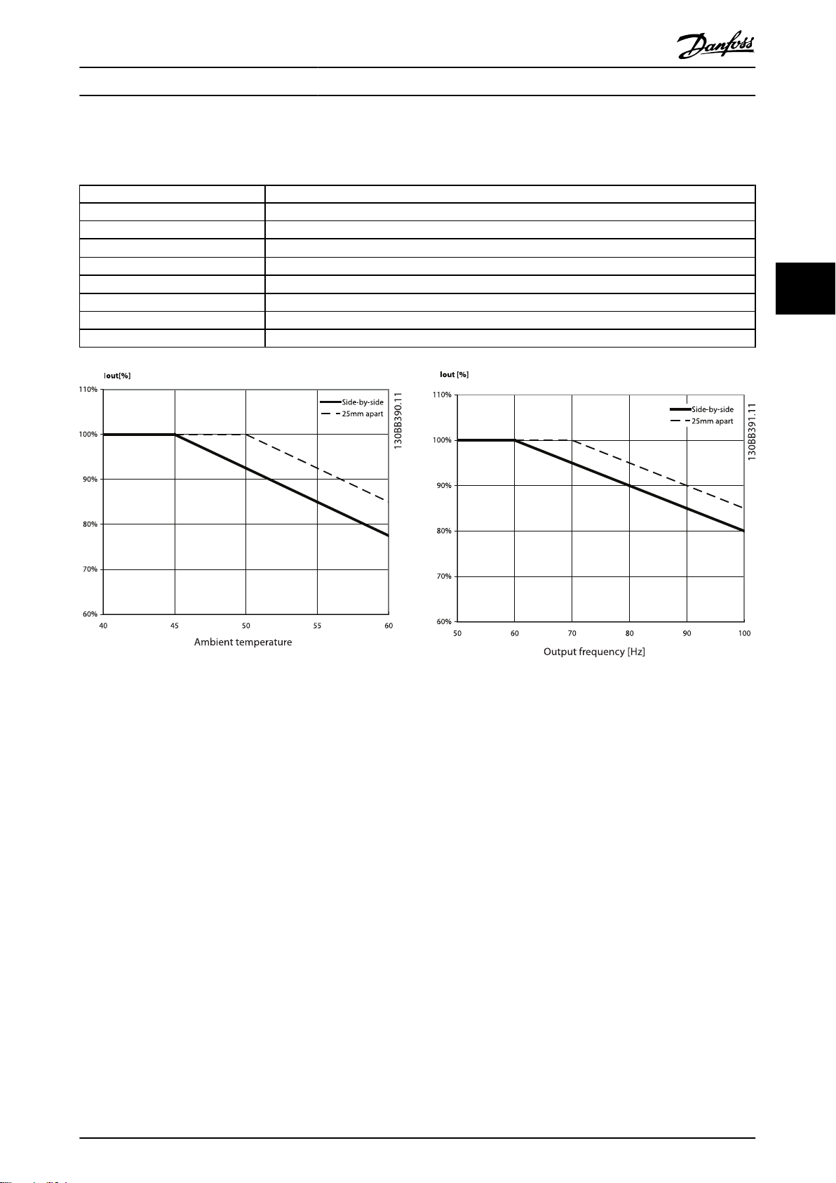
4.4.2 Sine-Wave Foot Print Filter
Technical Specification
Voltage rating 3 x 200-500V AC
Nominal current I¬N @ 50Hz 10 – 17A
Motor frequency 0-60Hz without derating. 100/120Hz with derating (see derating curves below)
Ambient temperature
Min. switching frequency f
Max. switching frequency f
Overload capacity 160% for 60 sec. every 10 minutes.
Enclosure degree IP20
Approval CE, RoHS
-25° to 45°C side by side mount, without derating (see derating curves below)
5kHz
min
16kHz
max
4 4
Illustration 4.2 Temperature Derating
Illustration 4.3 Output Frequency Derating
MG.90.N5.02 - VLT® is a registered Danfoss trademark 31
Page 33

PE
U
V W
130BB726.10
PE U V W
130BB727.10
How to Install Output Filters Design Guide
5 How to Install
5.1 Mechanical Mounting
5.1.1 Safety Requirements for Mechanical
Installation
WARNING
55
Pay attention to the requirements that apply to integration
and field mounting kit. Observe the information in the list to
avoid serious damage or injury, especially when installing
large units.
The filter is cooled by natural convection.
To protect the unit from overheating it must be ensured that
the ambient temperature does not exceed the maximum
temperature stated for the filter. Locate the maximum
temperature in the paragraph Derating for Ambient
Temperature.
If the ambient temperature is in the range of 45°C - 55°C,
derating of the filter will become relevant.
Illustration 5.1 Correct Installation
Mounting
5.1.2
All wall mounted filters must be mounted vertically
•
with the terminals at the bottom.
Do not mount the filter close to other heating
•
elements or heat sensitive material (such as wood)
The filter can be side-mounted with the frequency
•
converter. There is no requirement for spacing
between the filter and frequency converter.
Top and bottom clearance is minimum 100mm
•
(200mm for foot print filters).
The surface temperature of IP20/23 units does not
•
exceed 70°C.
The surface temperature of IP00 filters can exceed
•
70°C and a hot surface warning label is placed on
the filter.
Mechanical Installation of HF-CM
5.1.3
The HF-CM cores have an oval shape to allow easier installation. They should be placed around the three motor phases
(U, V and W). It is important to put all three motor phases
through the core, else the core will saturate. It is also
important not to put the PE or any grounding wires through
the core, else the core will loose its effect. In most
applications several cores have to be stacked.
Illustration 5.2 Wrong Installation. The PE should not go through
the core.
The cores can vibrate due to the alternating magnetic field.
When close to the cable’s isolation or other parts, it is
possible that the vibration causes the wearing of the core or
cable isolation material. Use cable ties to secure the cores
and cable.
32 MG.90.N5.02 - VLT® is a registered Danfoss trademark
Page 34

How to Install Output Filters Design Guide
5.1.4 Earthing of Sine-wave and dU/dt Filters
WARNING
The filter must be earthed before switching the power on
(high leakage currents).
Common mode interferences are kept small by ensuring that
the current return path to the frequency converter has the
lowest possible impedance.
Choose the best earthing possibility (e.g. cabinet
•
mounting panel)
Use the enclosed (in accessory bag) protective
•
earth terminal to ensure the best possible earthing
Remove any paint present to ensure good electrical
•
contact
Ensure that the filter and frequency converter make
•
solid electrical contact (high frequency earthing)
The filter must be earthed before switching the
•
power on (high leakage currents)
Screening
5.1.5
unscreened cables are employed it should be
ensured that the installation minimizes the
possibility of cross-couplings with other cables
carrying sensitive signals. This can be achieved by
measures such as cable segregation and mounting
in earthed cable trays.
The cable screen must be solidly connected at both
•
ends to the chassis (e.g. housing of filter and
motor).
If IP00 filters are installed in cabinets and screened
•
cables are used, the screen of the motor cable
should be terminated at the cabinet cable entry
point.
All screen connections must exhibit the smallest
•
possible impedance, i.e. solid, large area
connections, both ends of screened cable.
Maximum cable length between frequency
•
converter and output filter:
Below 7.5kW: 2m
Between 7.5 - 90kW: 5-10m
Above 90kW: 10-15m
NOTE
The cable between frequency converter and filter should be
kept as short as possible
5 5
It is recommended to use screened cables to reduce the
radiation of electromagnetic noise into the environment and
prevent malfunctions in the installation.
Cable between the frequency converter output (U,
•
V, W) and filter input (U1, V1, W1) to be screened or
twisted.
Use preferably screened cables between the filter
•
output (U2, V2, W2) and the motor. When
Illustration 5.3 Wiring Diagram
For F frame frequency converters parallel filters shall be used, one filter for each inverter module.
The cables or bus bars between inverter and filter should have the same length for each module.
The paralleling connection should be after the dU/dt filter/sine-wave filter, either at the filters' terminals or at the motor
terminals.
NOTE
More than 10m is possible but Danfoss strongly discourge
such installations, due to the risk of increased EMI and
voltage spikes on the filter terminals.
MG.90.N5.02 - VLT® is a registered Danfoss trademark 33
Page 35

C
B
a
A
b
f
e
130BB526.10
130BB879.10
How to Install Output Filters Design Guide
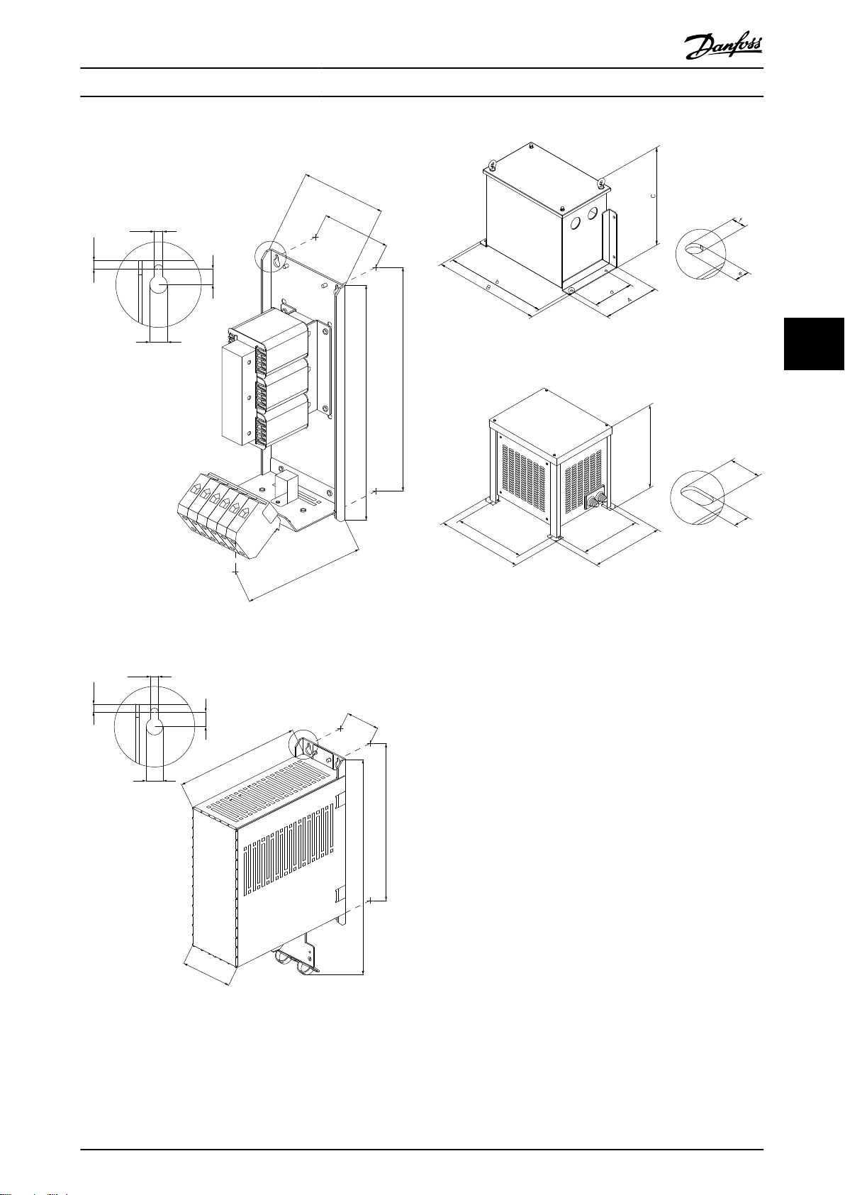
5.2 Mechanical Dimensions
5.2.1 Sketches
Floor Mounted Sine-wave filters
Wall Mounted Sine-wave filters
55
Illustration 5.6 IP23 Floor Mounted
Illustration 5.4 IP00 Wall Mounted
Illustration 5.5 IP20 Wall Mounted
Illustration 5.7 IP00 Floor Mounted
Illustration 5.8 IP20 Wall Mounted Foot Print Filters
34 MG.90.N5.02 - VLT® is a registered Danfoss trademark
Page 36
a
b
A
C
B
c
e
d
f
A
A
130BB523.10
b
a
A
C
B
e
f
A
d
c
A
130BB524.10
130BB875.10
C
B
a
A
b
f
e
130BB526.10
How to Install Output Filters Design Guide
Wall mounted dU/du filters
Illustration 5.9 IP00 Wall Mounted
Illustration 5.11 IP54 Floor/Wall Mounted
Illustration 5.12 IP23 Floor Mounted
5 5
Illustration 5.10 IP20 Wall Mounted
MG.90.N5.02 - VLT® is a registered Danfoss trademark 35
Page 37

b
B
a
A
e
f
C
A
A
130BB525.10
C
B
a
A
b
f
e
130BB526.10
30
88
5 1635
15
10.5
15
130BB527.10
18
88
5 1834
18
17.5
45
34
34
13
70
130BB528.10
23 24
18
34
8
ø13
88
80
25
12.5
23 34
62.5
130BB529.10
How to Install Output Filters Design Guide
Floor mounted dU/du filters
55
Illustration 5.13 IP00 Floor Mounted
Illustration 5.16 L-shaped Terminal Kit 130B3138
Illustration 5.14 IP23 Floor Mounted
Illustration 5.17 L-shaped Terminal Kit 130B3139
Illustration 5.15 L-shaped Terminal Kit 130B3137
36 MG.90.N5.02 - VLT® is a registered Danfoss trademark
Page 38

How to Install Output Filters Design Guide
5.2.2 Physical Dimensions
1)
L-shaped
terminal
kit
screw
torque
AWG Nm/ft-Ib Part no.
2
mm
c d e f kg
5 5
Enclosure Dimensions [mm] Weight Mounting Wire cross section Terminal
Code
number
b C
a B
A
(depth)
(width)
(height)
130B2835 IP00 295 279 115 85 170 11.5 13 6.2 6 4.6 wall 16 6 4/3 N/A
130B2836 IP20 370 279 118 85 242 11.5 13 6.2 6 6.3 wall 16 6 4/3 N/A
Table 5.1 200-690V dU/dt Filters - Physical Dimensions
130B2838 IP00 395 379 155 125 220 11.5 13 6.2 6 12.7 wall 50 1 6/4.5 N/A
130B2839 IP20 475 379 157 125 248 11.5 13 6.2 6 16.2 wall 50 1 6/4.5 N/A
130B2841 IP00 395 379 155 125 220 11.5 13 6.2 6 22 wall 50 1 6/4.5 N/A
130B2842 IP20 475 379 158 125 248 11.5 13 6.2 6 25.5 wall 50 1 6/4.5 N/A
130B2844 IP00 445 429 185 155 235 11.5 13 6.2 6 27 wall 95 3/0 12/9 N/A
130B2845 IP20 525 429 188 155 335 11.5 13 6.2 6 30 wall 95 3/0 12/9 N/A
130B2847 IP00 300 275 190 100 235 11 22 33 floor M10 18/13.3 130B3137
130B2848 IP23 425 325 700 660 620 13 17 64.5 floor M10 18/13.3 130B3137
130B2849 IP00 300 275 250 125 235 11 22 36 floor 2 x M10 30/22.1 130B3138
130B3850 IP23 425 325 700 660 620 13 17 67.5 floor 2 x M10 30/22.1 130B3138
130B2851 IP00 350 325 250 123 270 11 22 47 floor 2 x M10 30/22.1 130B3138
130B2852 IP23 425 325 700 660 620 13 17 78.5 floor 2 x M10 30/22.1 130B3138
MG.90.N5.02 - VLT® is a registered Danfoss trademark 37
For floor mounted filters, an optional terminal connection kit is available for the ease of installation. Please see the L-shaped terminal kit sketches.
130B2853 IP00 400 375 290 159 283 11 22 72 floor 4 x M10 30/22.1 130B3139
130B2854 IP23 792 660.5 940 779 918 11 22 182 floor 4 x M10 30/22.1 130B3139
1)
The kit is not included in the filter delivery and should be ordered separately.
Page 39

How to Install Output Filters Design Guide
1)
L-shaped
terminal kit
Terminal
screw torque
floor N/A
130B3137
floor
floor 130B3138
floor 130B3138
floor 130B3139
Max. wire cross section
direction
AWG Nm/ft-lb Part no.
2
mm
c d e f kg Wall/Floor
C
(depth)
b
2.5
wall 4 24 - 10 0.6/0.44 N/A
3.3
wall 4 24 - 10 0.6/0.44 N/A
4.6
205
wall 4 24 - 10 0.6/0.44 N/A
8 11 6.5 6.5
6.1
wall 4 24 - 10 0.6/0.44 N/A
7.8
wall 4 24 - 10 0.6/0.44 N/A
14.4
wall 16 20 - 4 2/1.5 N/A
17.7
260
wall 16 20 - 4 2/1.5 N/A
12 19 9 9
34
258
wall 50 6 - 1/0 8/5.9 N/A
12 19 9 20
36
wall 50 6 - 1/0 8/5.9 N/A
50
wall 50 6 - 1/0 15/11.1 N/A
floor 2.0-6.0 N/A
55
Mounting
B
(width)
a
A
Code number Enslosure Measurements / Dimensions Weight
38 MG.90.N5.02 - VLT® is a registered Danfoss trademark
(height
130B2404 IP00
200 190 75 60 205 7 8 4.5 5
200 190 75 60 205 7 8 4.5 5
268 257 90 70
268 257 90 70 205 8 11 6.5 6.5
268 257 130 90 205 8 11 6.5 6.5
330 312 150 120 260 12 19 9 9
430 412 150 120
530 500 170 125
610 580 170 125 260 12 19 9 20
610 580 170 135 260 12 19 9 20
130B2439 IP20 3.3
130B2406 IP00
130B2441 IP20 4.2
130B2408 IP00
130B2443 IP20 206 5.8
130B2409 IP00
130B2444 IP20 7.1
130B2411 IP00
130B2446 IP20 9.1
130B2412 IP00
130B2447 IP20 16.9
130B2413 IP00
130B2448 IP20 259 19.9
130B2281 IP00
130B2307 IP20 260 39
130B2282 IP00
130B2308 IP20 41
130B2283 IP00
130B2309 IP20 54
130B3179 IP00 520 - 470 400 334 175 13 26 95
130B3181 IP23 918 898 904 779 792 661 11 22 205
130B3182 IP00 580 - 470 400 311 150 13 26 127
130B3183 IP23 918 898 904 779 792 661 11 22 237
130B3184 IP00 520 - 500 450 350 200 13 26 197
130B3185 IP23 918 898 904 779 792 661 11 22 307
130B3186 IP00 520 - 500 450 400 250 13 26 260
130B3187 IP23 918 898 904 779 792 661 11 22 370
130B3188 IP00 520 - 500 450 400 250 13 26 265
130B3189 IP23 1161 1141 1260 1099 991 860 11 22 425
130B3191 IP00 620 - 620 575 583 250 13 26 410
130B3192 IP23 1161 1141 1260 1099 991 860 11 22 570
For floor mounted filters, an optional terminal connection kit is available for the ease of installation. Please see the L-shaped terminal kit sketches.
1)
Table 5.2 500V Sine-wave Filter - Physical dimensions
The kit is not included in the filter delivery and should be ordered separately.
Page 40

How to Install Output Filters Design Guide
1)
L-shaped
terminal kit
Terminal
screw torque
Max. wire cross section
direction
Mounting
AWG Nm/ft-lb Part no.
2
mm
N/A
floor 130B3139
N/A
N/A
N/A
5 5
Code number Enclosure Measurements / Dimensions Weight
c d e f kg Wall/Floor
C
(depth)
b
B
(width)
a
A
(height)
130B3193 IP00 620 - 620 575 583 250 13 26 410
130B3194 IP23 1161 1141 1260 1099 991 860 11 22 610
2 x 130B3188 IP00
2 x 130B3189 IP23
2 x 130B3191 IP00
2 x 130B3192 IP23
3 x 130B3188 IP00
3 x 130B3189 IP23
For floor mounted filters, an optional terminal connection kit is available for the ease of installation. Please see the L-shaped terminal kit sketches.
3 x 130B3191 IP00
3 x 130b3192 IP23
1)
Table 5.3 500V Sine-wave Filter - Physical Dimensions
The kit is not included in the filter delivery and should be ordered separately.
MG.90.N5.02 - VLT® is a registered Danfoss trademark 39
Page 41
How to Install Output Filters Design Guide
1)
L-shaped
terminal kit
torque
Terminal screw
55
Max. wire cross section
Mounting
Weigh
2
direction
t
C
AWG Nm/ft-lb Part no.
mm
c d e f kg wall/floor
)
depth
wall 16 20 - 8 2/1.5 N/A
floor 16 20 - 8 15/11.1 N/A
floor 50 8 - 6 15/11.1 N/A
floor 95 6 - 4 15/11.1 N/A
floor 95 4 - 2 15/11.1 N/A
floor Ø10.5 2 - 1/0 15/11.1 130B3137
floor Ø10.5 2/0 - 4/0 18/13.3 130B3137
floor 2 x Ø13 2/0 - 4/0 18/13.3 130B3138
floor 2 x Ø13 4/0 - 5/0 18/13.3 130B3138
floor 2 x Ø13 4/0 - 5/0 30/22.1 130B3138
floor 4 x Ø13 5/0 30/22.1 130B3139
5/0 - 6/0 30/22.1 N/A
6/0 30/22.1 N/A
6/0 30/22.1 N/A
b
B
width)
a
A
(height)
130B3195 IP00 465 449 115 85 270 225 13 6.2 6.5 18
130B3196 IP20 465 449 118 85 243 - 13 6.2 6.5 21
130B4112 IP00 505 489 155 125 270 225 13 6.2 6.5 27
130B4113 IP23 505 489 158 125 310 - 13 6.2 6.5 31
130B4114 IP00 625 609 155 125 370 300 13 6.2 6.5 43
130B4115 IP23 625 609 158 125 310 - 13 6.2 6.5 49
130B4116 IP00 520 - 470 400 332 175 13 26 107
130B4117 IP23 715 699 798 676 620 502 11 22 142
130B4118 IP00 520 - 470 400 332 175 13 26 123
130B4119 IP23 715 699 798 676 620 502 11 22 160
130B4121 IP00 470 - 500 450 400 200 13 26 160
130B4124 IP23 918 898 940 779 792 661 11 22 270
130B4125 IP00 535 - 660 575 460 250 13 26 315
130B4126 IP23 1161 1141 1260 1099 991 860 11 22 475
130B4129 IP00 660 - 800 750 610 275 13 26 513
130B4151 IP23 1161 1141 1260 1099 991 860 11 22 673
130B4152 IP00 660 - 800 750 610 275 13 26 485
130B4153 IP23 1161 1141 1260 1099 991 860 11 22 645
130B4154 IP00 660 - 800 750 684 350 13 26 600
Code number Enclosure Measurements / Dimensions
40 MG.90.N5.02 - VLT® is a registered Danfoss trademark
130B4155 IP23 1161 1141 1260 1099 991 860 11 22 760
130B4156 IP00 490 - 800 750 713 375 13 26 745
130B4157 IP23 1161 1141 1260 1099 991 860 11 22 905
2 x 130B4152 IP00
2 x 130B4153 IP23
For floor mounted filters, an optional terminal connection kit is available for the ease of installation. Please see the L-shaped terminal kit sketches.
2 x 130B4154 IP00
3 x 1304155 IP23
2 x 130B4155 IP23
3 x 130B4154 IP00
1)
The kit is not included in the filter delivery and should be ordered separately.
Table 5.4 690V Sine-wave filter - Physical Dimensions
Page 42

How to Install Output Filters Design Guide
2
mm
Section
Max. Wire Cross
Direction
5 5
c d e f [kg]
b C
a B
(depth)
(width)
(height)
Code Number Foot Print Dimensions Weight Mounting
A
130B2542 A2 282 257 90 70 202 10 11 6 15 8 wall 4
130B2543 A3 282 257 130 110 212 10 11 6 15 11.5 wall 4
Table 5.5 Foot Print Sine-Wave Filter - Technical Data
MG.90.N5.02 - VLT® is a registered Danfoss trademark 41
Page 43

How to Install Output Filters Design Guide
1
L-shaped
terminal
kit
partnumb
er
Terminal
screw
torque
AWG Nm/ft-lb
section
Wire cross
2
55
Mountin
g
C
B
A
Part number Enclosure Dimensions [mm] Weight
(depth) c d e f kg mm
(width) b
(heigth) a
IP54
130B2837 IP54 200 130 320 304 250 9 9 15.7 floor 16 6 4/3 N/A
130B2840 IP54 230 160 420 400 355 9 9 39.8 floor 50 1 6/4.5 N/A
130B2843 IP54 275 200 470 446 460 11 14 59.6 floor 50 1 6/4.5 N/A
130B2846 IP54 275 200 470 446 460 11 14 61.8 floor 95 3/0 12/9 N/A
Table 5.6 200-690V dU/dt Filters - Physical Dimensions
42 MG.90.N5.02 - VLT® is a registered Danfoss trademark
Page 44

How to Programme the Freque... Output Filters Design Guide
6 How to Programme the Frequency Converter
The VLT® switching frequency must be set to the
•
value specified for the individual filter. Please
consult the VLT
corresponding parameter values.
With an output filter installed only a reduced
•
Automatic Motor Adaption (AMA) can be used.
®
Programming Guide for the
NOTE
Sine-wave filters can be used at switching frequencies higher
than the nominal switching frequency, but should never be
used at switching frequencies with less than 20% lower than
the nominal switching frequency.
6.1.1 Parameter Settings for Operation with Sine-wave Filter
Parameter no. Name Suggested setting
14-00 Switching Pattern For Sine-wave filters choose SFAVM
14-01 Switching Frequency Choose value for individual filter
14-55 Output Filter Choose Sine-wave filter fixed
14-56 Capacitance Output Filter
14-57 Inductance Output Filter
1
) For FLUX control principle only. Values can be found in 4.2 Electrical Data - dU/dt Filters and 4.3 Electrical Data - Sine-wave Filters.
NOTE
du/dt filters, unlike Sine-wave filters, can be used at lower
switching frequency than the nominal switching frequency,
but higher switching frequency will cause the overheating of
the filter and should be avoided.
Set the capacitance
Set the inductance
1
1
6
6
MG.90.N5.02 - VLT® is a registered Danfoss trademark 43
Page 45

Index Output Filters Design Guide
Index
A
Abbreviations........................................................................................... 3
Accessory Bag........................................................................................ 33
Acoustic Noise................................................................................... 14, 5
Aggressive Environments.................................................................. 12
C
Cable Length.......................................................................................... 12
Capacitance............................................................................................ 12
Capacitors................................................................................................ 12
CE Conformity And Labelling............................................................. 4
Common-mode Voltage....................................................................... 8
Conducted Noise.................................................................................. 11
Cut Off Frequency................................................................................ 12
D
DU/dt Ratio................................................................................................ 5
Inductance.............................................................................................. 12
Inductors.................................................................................................. 12
Insulation
Insulation............................................................................................... 5
Stress.................................................................................................... 12
L
LC-filter..................................................................................................... 14
M
Magnetostriction..................................................................................... 7
Maximum Cable Length..................................................................... 33
Motor
Bearing Stress.................................................................................... 12
Cable....................................................................................................... 5
Mounting................................................................................................. 32
N
NEMA........................................................................................................... 6
NEMA-MG1............................................................................................. 12
E
Earthing.................................................................................................... 33
Electromagnetic
Electromagnetic............................................................................. 5, 8
Emissions............................................................................................ 14
EMC
EMC....................................................................................................... 12
Performance...................................................................................... 12
F
Flash Over................................................................................................ 12
G
General
Purpose Motors................................................................................ 13
Warning................................................................................................. 3
H
Harmonics.................................................................................................. 8
High Frequency....................................................................................... 8
High-frequency Noise........................................................................... 8
High-voltage Warning........................................................................... 3
P
Phase-to-phase........................................................................................ 7
Pulse Reflections................................................................................... 14
Pulsewidth Modulated.......................................................................... 7
R
Reflection Coefficient........................................................................ 5, 6
Regenerative Braking.......................................................................... 12
Retrofit...................................................................................................... 13
RFI Filter................................................................................................... 12
Ringing Oscillation................................................................................. 8
S
Safety Requirements For Mechanical Installation.................... 32
Screened Cables.................................................................................... 33
Sinusoidal.............................................................................................. 7, 8
Step Up Applications.......................................................................... 15
T
The Low-voltage Directive (73/23/EEC).......................................... 4
Tr................................................................................................................... 6
I
IEC
IEC............................................................................................................ 6
600034-17........................................................................................... 13
60034-17............................................................................................. 12
Impedance................................................................................................. 5
44 MG.90.N5.02 - VLT® is a registered Danfoss trademark
U
Upeak.......................................................................................................... 6
Page 46

Index Output Filters Design Guide
V
Voltage
Drop...................................................................................................... 12
Peaks..................................................................................................... 12
W
Wave Reflection....................................................................................... 5
MG.90.N5.02 - VLT® is a registered Danfoss trademark 45
Page 47

www.danfoss.com/drives
130R0457 MG90N502 Rev. 2011-01-17
*MG90N502*
 Loading...