

Page 1

FC 300 DeviceNet and Allen Bradley Control logix 5550
Introduction ................................................................. 2
FC 300 DeviceNet card ............................................ 2
Creation of an EDS file ............................................. 4
Configuring the FC 300 with RS Networx ......... 7
I/O communication with RS Logix 5000 ....... 1 0
Explicit messages with RS Logix 5000........... 1 2
MN.33.B1.02 - VLT is a registered Danfoss trademark
1
Page 2
FC 300 DeviceNet and Allen Bradley Control logix 5550
Introduction
This application note describes how to set
up DeviceNet communication between a
Danfoss FC 300 frequency converter and
1756-DNB DeviceNet Scanner from Allen
Bradley. It is assumed that you have some
knowledge of RS Logix, the DeviceNet
Scanners and ladder logic.
This note describes:
z FC 300 DeviceNet card
z Configuration of the FC 300 with RS
Networx
z ADR - Auto Device Recovery
z I/O communication with RS Logix 5000
z Explicit messages with RS Logix 5000
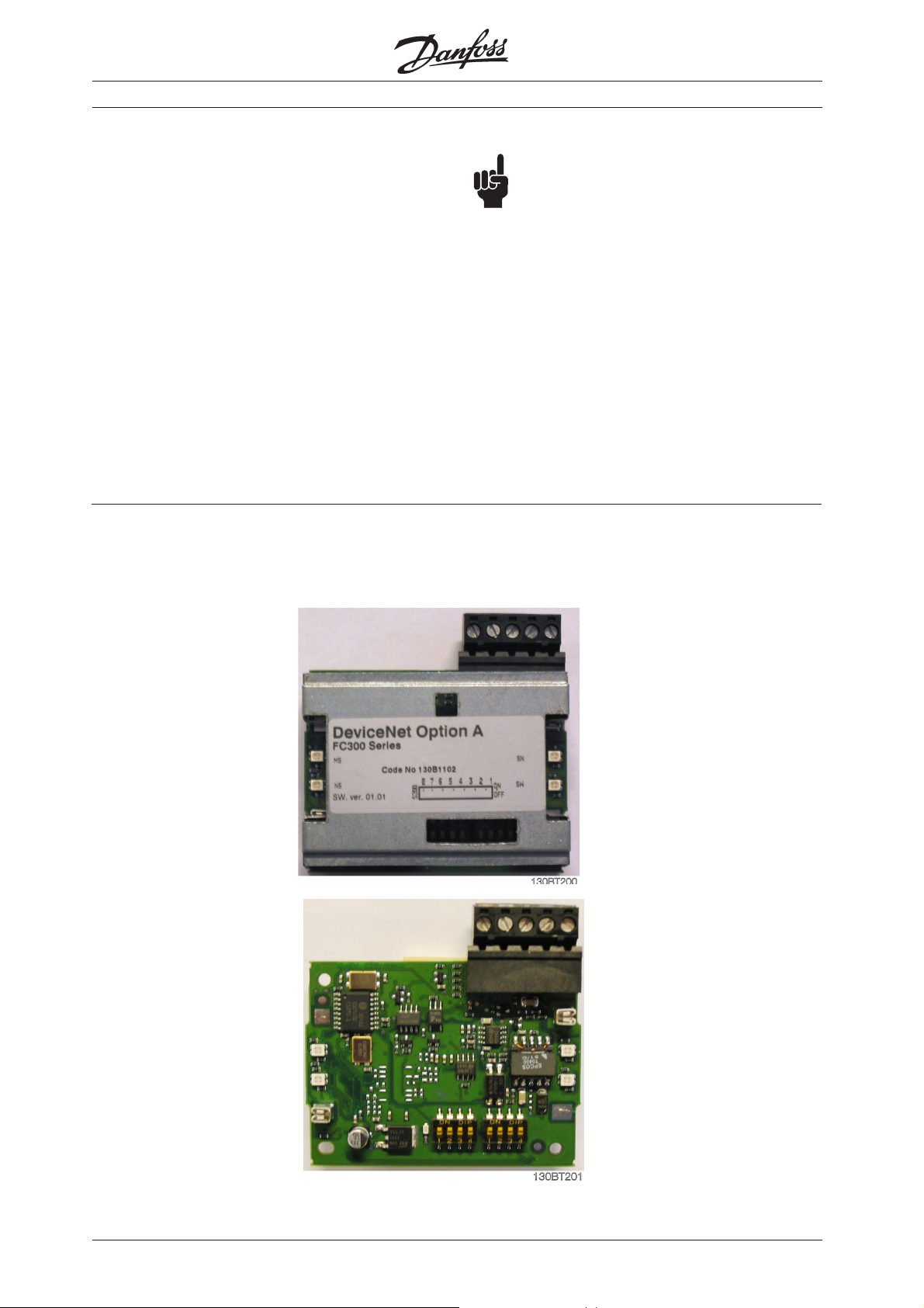
FC 300 DeviceNet card
The photo shows the DeviceNet card
which can be installed in FC 300 Series.
NOTE!:
The examples do not describe all the
functions needed for a real application, for
example error handling.
The examples are based upon that a RS
Logix5000 project has been created, and
the 1756-DNB has been added to the I/O
configuration.
Details of some of the components/
software:
FC 300 with DeviceNet version 2.5.
1756-DNB Series A Firmware Revision 6.002
RS Networx version 5.11.00
RS Logix 5000 version 13.00.00
MS Module status LED
NS Network status LED
NS Network status LED
MS Module status LED
Address switch and
baud rate setting
2
MN.33.B1.02 - VLT is a registered Danfoss trademark
Page 3
FC 300 DeviceNet and Allen Bradley Control logix 5550
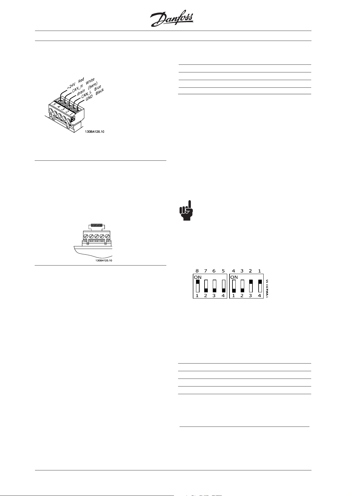
DeviceNet connection
DeviceNet termination
Termination resistors should be installed at
each end of the bus line.
The resistors must be mounted between
terminal 2 CAN_L and terminal 4 CAN_H and
should have the following specification:
121 Ohm, 1 % Metal film and 1/4 Watt
Cable length
Baud rate Max. total cable length [m]
125 kBaud 500
250 kBaud 250
500 kBaud 100
Address and baud rate setting
Dip switch 1-6 set the DeviceNet address/
Mac ID and 7-8 the baud rate.
Switch 6 is the Most Significant Bit (MSB)
and Switch 1 is the Least Significant Bit
(LSB).
When setting the address/Mac ID you must
ensure that each device on the network has
a unique address. The Baud rate can be
read in parameter 10-01 Baud rate Select
and the address/Mac ID can be read in
parameter 10-02 Mac ID.
NOTE!:
Switch off the power supply before
changing the hardware switches.
LEDs
For the Module Status LED:
1 . When the LED is off, no power is applied
to the option.
2. When the LED is green, the device is
operational
3. When the LED is flashing green, the
device is in standby
4. When the LED is flashing red, the device
detects a minor fault
5. When the LED is red, the device detects
an unrecoverable fault
6. When the LED is flashing red/green, the
device is self testing
For the Network Status LED:
1. When the LED is off, the network is nonpowered/not online
2. When the LED is flashing green, the
network is online but not connected
3. When the LED is green, the network is
online and connected
4. When the LED is flashing red, the
network has a connection time-out
5. When the LED is red, the network has a
critical link failure.
MN.33.B1.02 - VLT is a registered Danfoss trademark
If the address is to be set to 3 and the Baud
rate to 500 k Baud, the dip switches should
be set as follow:
ON = 1
OFF = 0
Switch Settings for DeviceNet Module Baud
rate:
Baud Switch Switch
Rate Setting Setting
87
125 kBPS 0 0
250 kBPS 0 1
500 kBPS 1 0
125 kBPS 1 1
3
Page 4
FC 300 DeviceNet and Allen Bradley Control logix 5550
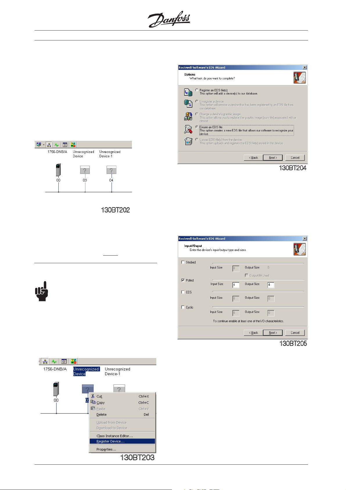
Creation of an EDS file
In this example the DeviceNet network consists of a
FC 301 set up to address 3, a FC 302 set up to
address 4 and the Master (1756-DNB) set up to
address 0.
Start RS Networx and a new project.
Go online and browse the Network via RS Linx. If
RS Networx does not have an EDS (Electronic Data
Sheet) installed the Device will be shown as an
Unrecognized Device.
The EDS Wizard is started and click on Next.
Choose Create an EDS file and click on Next.
By Input/Output choose a type and a size. Note
that Strobed is not supported FC 301 and 302.
By the FC 300 series the EDS file can be created
from the Drive via RS Networx. It is also possible to
download the EDS file from
www.danfoss.com/BusinessAreas/DrivesSolutions
NOTE!:
The EDS file does not contain all
parameters but a selected, limited number
of parameters. Note that an EDS file needs
to be created for both FC 301 and 302.
To create an EDS file right click on the
"Unrecognized Device" and choose Register
Device.
http://
Creation of an EDS file
Click on Next and the EDS file will start to be
created from the FC 300 Drive.
4
MN.33.B1.02 - VLT is a registered Danfoss trademark
Page 5
FC 300 DeviceNet and Allen Bradley Control logix 5550
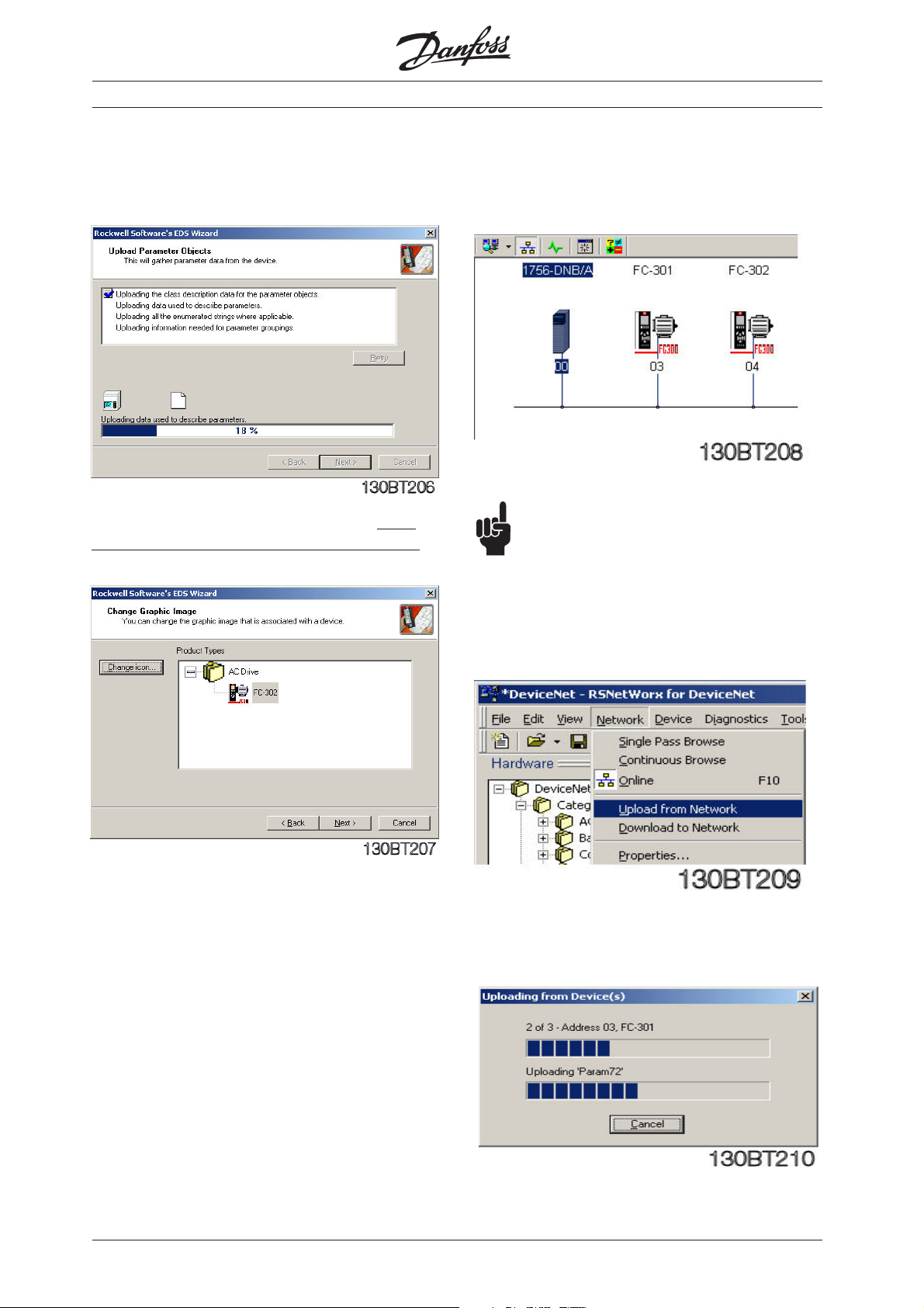
After the Parameter Objects that is used to create
the EDS file have been uploaded an Icon can be
linked to the FC 300 EDS file.
The FC 300 Icon can be downloaded from http://
www.danfoss.com/BusinessAreas/DrivesSolutions
After the EDS files for FC 301 and 302 have
been created you can browse the Network
again and the Drives will be shown.
NOTE!:
As the EDS files for FC 301 and 302 will
cover all motor and voltage sizes it is necessary to
upload the factory setting by the first
commissioning. This will secure that the correct
motor parameters are used in the EDS file.
Click on Network and Upload from Network.
MN.33.B1.02 - VLT is a registered Danfoss trademark
Now all Devices on the DeviceNet will be
read.
5
Page 6
FC 300 DeviceNet and Allen Bradley Control logix 5550
Creation of an EDS file
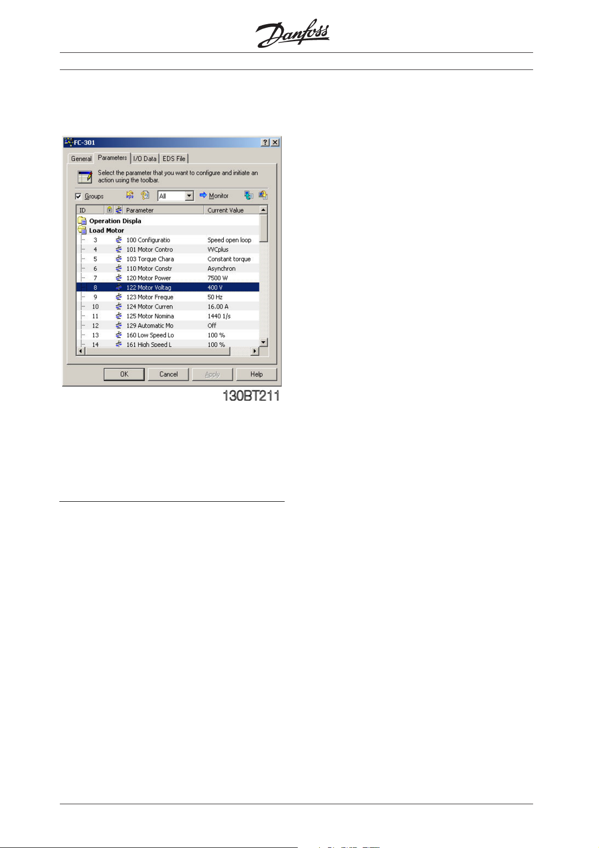
Double click on one of the FC 300 and the
parameters can be changed and downloaded.
Parameter written from RS Networx via the EDS file
is from the factory stored in RAM. To store the data
in non-volatile memory parameter 10-31 Store Data
Values or parameter 10-33 Store Always can be
used.
6
MN.33.B1.02 - VLT is a registered Danfoss trademark
Page 7

FC 300 DeviceNet and Allen Bradley Control logix 5550
Configuring the FC 300 with RS Networx
Double click on the 1756-DNB Scanner.
Click on Scanlist and add the two Devices
from Available Devices to the Scanlist.
Click on one of the FC 300 and on Edit I/O
Parameters.
The Polled input/output byte size needs to match
the actual instance type in parameter 10-10
Process Data Type Selection according to the table
below.
Click on Input and if you click on AutoMap
the I/O area of the FC 300 Devices will be
added to the first free area, here I 0.0.
Note that the I/O area of the Control logix Scanner
is organised as 32 bits (double word). This may vary
by other Scanner types.
This means that the FC 301 (address 3) Status word
will be read from the I/O area I:0.0 to I:0.15 and the
Main Actual Value from I:0.16 to I:0.32.
Parameter Polled size Polled size
10-10 input output
Instance 20/70 4 bytes 4 bytes
Instance 21/71 4 bytes 4 bytes
Instance 100/150 4 bytes 4 bytes
Instance 101/151 8 bytes 8 bytes
In this example FC 301 (address 3) is setup to Polled
I/O with 4 bytes using instance 100/150 and FC 302
(address 4) is setup to Polled I/O with 8 bytes using
instance 101/151.
The last four bytes of Instance 101/151 can be
configured in parameter 10-11 Process Data Write
and 10-12 Process Data Read.
Do the same with the Output to map Control word
and reference.
MN.33.B1.02 - VLT is a registered Danfoss trademark
7
Page 8

FC 300 DeviceNet and Allen Bradley Control logix 5550
Configuring the FC 300 with RS Networx
Auto-Device Replacement, or ADR, is a feature that
automatic replaces a failed device on a DeviceNet
network and returns it to the original setup without
having to use a software tool. It consists of two
features:
z Configuration Recovery, CR.
With this feature the Scanner will download the stored configuration (EDS file) to
the FC 300 before it begins to exchange
I/O data with that device. Notice this will
happen by each power up of the Master,
so this will expand the power up time.
z Auto Address Recovery, AAR.
With this feature the scanner (master)
will change the device node address from
63 (the default address) to the original
address.
Example: The connection between the
Scanner and FC 301 at node address #3
is broken and the FC 301 needs to be
replaced. In this situation the Scanner
will continually query for a new FC 301 at
node address #63. When a new FC 301 is
power up with the factory settings and if
the Electronic Key of the device that the
scanner lost at node address #3
matches, it will change the node address
from #63 to #3.
After Auto Address Recovery the EDS file
will be downloaded the node address #3.
The FC 300 can now be seen as an available device
for ADR.
Click on each node and click on „Load Device
Config“. Click also on Configuration Recovery and
Auto-Address Recovery by ADR Settings if these
functions are require.
Click on ADR to set up the ADR menu.
8
This indicates the size of the Device
configuration (EDS file).
MN.33.B1.02 - VLT is a registered Danfoss trademark
Page 9

FC 300 DeviceNet and Allen Bradley Control logix 5550
Configuring the FC 300 with RS Networx
Click on Enable Auto-Address Recovery and
a Warning will appear. Click Yes to this
Warning and set the PLC in Stop (Program).
Download the configuration to the Scanner
and turn the key on the Scanner to Run to
start to communicate with the slaves.
MN.33.B1.02 - VLT is a registered Danfoss trademark
9
Page 10

FC 300 DeviceNet and Allen Bradley Control logix 5550
I/O communication with RS Logix 5000
Start RS Logix 5000 and a new project.
Make the I/O configuration and click on
Controller tags.
Click on Local data for the DeviceNet
module. Now you can see the full input area
of the DeviceNet system.
Device Address Input PCD 1 PCD 2 PCD 3 PCD 4
Status Word Main Actual Motor Motor
FC 301 3 Local:2:I.Data[0] 0607 Hex 0000 Hex - FC 302 4 Local:2:I.Data[1] 0F07 Hex 2000 Hex - FC 302 4 Local:2:I.Data[2] - - A1 Hex= FB Hex=
Choose to see the format in Hex.
See a detailed description of the status word in the
FC 300 DeviceNet Operating Instructions
(MG33DXYY).
In this example Local:2:I.Data indicates the
following:
Value current frequency
1.61 A 25.1 Hz
Example on status words from FC 301/302
(par. 1010 Process Data Type Selection =
Instance 100/150 or 101/151):
0607 Hex: Stand by
0F07 Hex: Speed = ref. VLT running
0E07 Hex: Speed ≠ ref. i.e. ramping.
VLT running
0F87 Hex: Warning
10
MN.33.B1.02 - VLT is a registered Danfoss trademark
Page 11

FC 300 DeviceNet and Allen Bradley Control logix 5550
I/O communication with RS Logix 5000
Click on the Local output data. Now you
can see the full Output area of the
DeviceNet system.
Choose to see the format in Hex.
See a detailed description of the control word in the
FC 300 DeviceNet Operating Instructions
(MG33AXYY).
To start the FC 300 when using Instance
100/150 or 101/151 the start command
should be 047C Hex. The Reference goes
from 0 – 4000 Hex, corresponding to 0 –100
%.
Device Address Output PCD 1 PCD 2 PCD 3 PCD 4
Control Word Reference Ramp 1 Ramp 1
FC 301 3 Local:2:O.Data[0] 043C Hex 1000 Hex - FC 302 4 Local:2:O.Data[1] 047C Hex 2000 Hex - FC 302 4 Local:2:O.Data[2] - - 64 Hex= 12C Hex=
In this example Local:2:O.Data[0] indicates
the following:
0-4000 hex up P.341 down P.342
1.00 sec 3.00 sec
Example on Control words to the FC 300
(par. 512 Telegram profile = FC Drive [1]):
047C Hex: Start via ramp time 1
043C Hex: Stop via ramp time 1
0474 Hex: Coast
046C Hex: Quick Stop via Ouick Stop ramp
time
847C Hex: Reversing and start
MN.33.B1.02 - VLT is a registered Danfoss trademark
Example on reference to the FC 300 (par.
303 Max. reference = 1500 rpm):
1000 Hex ~ 25 % reference = 12.5 Hz
2000 Hex ~ 50 % reference = 25.0 Hz
4000 Hex ~ 100 % reference = 50.0 Hz
11
Page 12

FC 300 DeviceNet and Allen Bradley Control logix 5550
Explicit messages with RS Logix 5000
Explicit messages is used to read or write from the
PLC to FC 300 parameters.
In this example an explicit message will be set up to
read parameter 16-13 Frequency and an explicit
message to write to parameter 341 Ramp up time
1.
Click on Controller Tags and add a new tag
called MESSAGE.
Click on box next to DINT and in Select
Data type choose MESSAGE.
12
MN.33.B1.02 - VLT is a registered Danfoss trademark
Page 13

FC 300 DeviceNet and Allen Bradley Control logix 5550
Explicit messages with RS Logix 5000
Add a new tag called Motor_frequency.
Click on box next to INT and in Select Data type
choose INT with an Array of 0.
Now all the Tags are created to read the Motor
frequency parameter 16-13 on address number 3.
By I/O configuration double click on 1756DNB Scanner.
Give the Scanner a name, for example Dnet
and click on OK.
MN.33.B1.02 - VLT is a registered Danfoss trademark
13
Page 14

FC 300 DeviceNet and Allen Bradley Control logix 5550
Explicit messages with RS Logix 5000
Click on Main routine and add a new rung.
Click on the Input/Output tag and drag and
drop a MSG block to the rung.
Click on blue ? and choose the MESSAGE
tag from the list.
Click on box next to MESSAGE to configure
the read command of parameter 16-13 Motor
frequency.
Add an input (Examine Off) to the Message
block and set it to MESSAGE.EN.
In this example the Scanner always reads the Motor
frequency.
Set the Message Configuration to the following:
Message Type: CIP Generic
Service Type: Get Attribute Single (Read command)
Class: 74 Hex (116 dec). This is the Class ID for Group 1600.
See page 17.
Instance: 1 Hex. Set always this to 1.
Attribute: 71 Hex (113 dec). The attribute is the last two digits of the
parameternumber + 100.
Set the Destination to the Motor_frequency tag and the message is now set up to read par. 16-13 Motor
frequency.
14
MN.33.B1.02 - VLT is a registered Danfoss trademark
Page 15

FC 300 DeviceNet and Allen Bradley Control logix 5550
Explicit messages with RS Logix 5000
Click on Communication and create a path
to the FC 301 at address 3.
Dnet is the name of 1756-DNB Scanner and
2 is a fixed number and 3 is the address of
FC 301. Click Apply and OK.
Save the program and download it to the scanner.
Click on controller tags and give the FC 301 a start
signal.
By Motor_frequency the actual frequency is
shown. 250 means that the actual frequency is 25.0 Hz due to the conversion
index of -1.
MN.33.B1.02 - VLT is a registered Danfoss trademark
15
Page 16

FC 300 DeviceNet and Allen Bradley Control logix 5550
Explicit messages with RS Logix 5000
If you want to write to a parameter you
must use the Service type Set Attribute
Single and create a source element where
the parameter value can be defined.
The Source Length should match the Data
type size of the parameter. The Data type
can be seen by the factory settings in the
Operating Instruction.
16
MN.33.B1.02 - VLT is a registered Danfoss trademark
Page 17

FC 300 DeviceNet and Allen Bradley Control logix 5550
Explicit messages with RS Logix 5000
Parameter range: Class:
Group 0-00 - 0-99 Operation & Display Class 100 (64 Hex)
Group 1-00 - 1-99 Load & Motor Class 101 (65 Hex)
Group 2-00 - 2-99 Brakes Class 102 (66 Hex)
Group 3-00 - 3-99 Reference / Ramps Class 103 (67 Hex)
Group 4-00 - 4-99 Limits / Warnings Class 104 (68 Hex)
Group 5-00 - 5-99 Digital In / Out Class 105 (69 Hex)
Group 6-00 - 6-99 Analog In / Out Class 106 (6A Hex)
Group 7-00 - 7-99 Controls Class 107 (6B Hex)
Group 8-00 - 8-99 Comm. and Options Class 108 (6C Hex)
Group 10-00 - 10-99 Can Fieldbus Class 110 (6E Hex)
Group 13-00 - 13-99 Smart Logic Class 113 (71 Hex)
Group 14-00 - 14-99 Special Functions Class 114 (72 Hex)
Group 15-00 - 15-99 Drive Information Class 115 (73 Hex)
Group 16-00 - 16-99 Data Readouts Class 116 (74 Hex)
Group 17-00 - 17-99 Motor Feedback Option Class 117 (75 Hex)
Instance Description:
In the Danfoss FC 300 Series we only
handle Instance 1, so always leave this at
the value of 1.
Attribute Description:
The attribute for the FC 300 parameters are the 2
(two) last digits of the Parameter + 100.
By following this structure all 1 dimensional
parameters can be accessed by Explicit
Message.
As example for Parameter 1662,
FC 300 Parameter FC 300 Parameter
FC 300 Parameter
FC 300 Parameter FC 300 Parameter
16-62 116 1 162
ClassClass
Class
ClassClass
InstanceInstance
Instance
InstanceInstance
AttributeAttribute
Attribute
AttributeAttribute
MN.33.B1.02 - VLT is a registered Danfoss trademark
17
 Loading...