

Fact Sheet
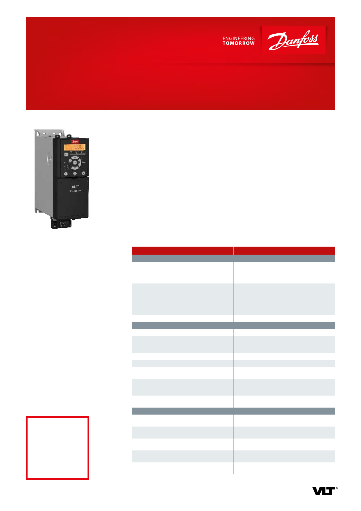
VLT® Midi Drive FC 280
Flexible. Communicative. Easy to use.
Access your true high-efficiency
potential with the VLT® Midi Drive
FC 280, the evolution of the popular
VLT® 2800 drive. Profit from new savings, with a wide range of features
designed to make installing, using,
and maintaining the drive as simple
and as easy as possible – just set and
forget.
This AC drive delivers precise and
efficient motor control for machine
builders in the food and beverage,
material handling, and processing
industries. It is strong on control performance, functional safety, and flexible
fieldbus communication.
It’s also an easy retrofit for the
VLT® 2800 in established plant or
machinery concepts.
Active power factor
correction for singlephase units reduces
harmonics to less
than
8% THDi
The right mix of features ensures the
AC drive suits your task, whether for
conveyor systems, mixers, and packag-
Integrated features free you from
finding space and budget to install
extra components:
ing systems or driving pumps, fans, and
compressors.
VLT® Midi Drive saves installation time,
with all pluggable connectors, and USB
n Harmonic mitigation
n RFI filter
n Dual-channel Safe Torque Off (STO)
n Brake chopper
port for convenient PC connection. For
easy and intelligent commissioning,
transfer, or programming of factory
settings, use the handy VLT® Memory
Module.
Product range
3 x 380-480 V ...................................0.37-22 kW
3 x 200-240 V ..................................0.37-3.7 kW
1 x 200-240 V ..................................0.37-2.2 kW
Set-up wizards simplify commissioning
for common applications.
Feature Benefit
Integrated harmonics and EMC design
Integrated DC choke or active power factor
correction (PFC)
Integrated EMC filter
RFI switch – Operates safely on IT mains
Easy to install and set up
Pluggable terminals – Fast installation and unit exchange
USB port
Application set-up wizards – Easy commissioning
Enhanced numerical LCP (option) – Cost effective user interface
Graphical LCP supporting various languages,
including adapter (option)
Memory module (option)
Memory module reader (option)
Strategic design for applications, safety, and motor control
Integrated Safe Torque Off (STO), dual channel
Control algorithm runs both
induction and PM motors
Integrated brake chopper for 3-phase drives in all
power sizes up to 22 kW
Side-by-side or horizontal mounting, without
derating and clearance
Operates at up to 45 °C without derating and
clearance
– Saves installation time and panel space
requirements
– Improves power supply quality
– Reduces effective input current/VA rating
– Avoids malfunction and improves reliability
of surrounding components
– Saves installation time and panel space
requirements
– Proven compliance to Cat. C2/EN 61800-3
(Class A1/EN 55011)
– Easy PC connection for troubleshooting
or commissioning
– No need for adapter or PC-USB driver
– Easy set-up in one of seven main languages
– Fast troubleshooting
– Convenient transfer of parameter set-up
– Easy firmware updates
– Easy and fast commissioning
– Convenient transfer files to and from the
VLT® Memory Module MCM 102 via PC
– Eliminates external components
– Enables reliable functional safety
– Freedom to choose the best
high-efficiency motor for the task
– No cost for external braking chopper
– Allows flexible mounting and saves cabinet
space and cost
– Saves cost for external cooling and reduces
downtime for overtemperature failures
drives.danfoss.com
Integrated harmonic mitigation
In compliance with IEC/EN 61000-3-2/
61000-3-12, the integrated DC chokes
for all 3-phase units reduce harmonics
to less than 48% THDi.
For single-phase units the harmonics
are less than 8% thanks to the
integrated active PFC.
Integrated RFI lter
Built-in filters not only save space, but
also eliminate extra costs for fitting,
wiring and material.
Dual-channel Safe Torque O
The Safe Torque Off (STO) function is a
component in a safety control system.
STO prevents the unit from generating
the energy that is required to rotate the
motor, which ensures safe conditions in
emergency situations.
PM motor compatibility
The VLT® Midi Drive provides highly
efficient permanent magnet (PM)
motor control in open loop under
V VC+ in the whole power range.
Your choice of eldbus
n PROFINET with dual port
n POWERLINK with dual port
n EtherNet/IP™ with dual port
n PROFIBUS
n CANopen
n Modbus RTU and FC Protocol are
integrated as standard
The optional 24 V DC back-up
power supply keeps the fieldbus
communication on, while disconnected
from mains.
Specifications
Mains supply (L1, L2, L3)
Supply voltage
Supply frequency 50/60 Hz
Displacement power factor (cos φ) Near unity (> 0.98)
Switching frequency on input supply L1, L2, L3 Switching maximum 2 times/minute
Output data (U, V, W)
Output voltage 0-100% of supply voltage
Switching on output Unlimited
Ramp times 0.01-3600 s
Frequency range 0-500 Hz
Programmable digital inputs and outputs
Digital inputs / digital outputs* 6 (7) / 1
Logic PNP or NPN
Voltage level 0-24 V DC
One of 6 digital inputs can be configured as digital output or pulse output. One of analog inputs can be configured as an extra digital input, thereby bring the quantity of digital inputs to 7.
Pulse and encoder inputs
Pulse inputs / encoder inputs** 2/2
Voltage level 0-24 V DC
**Note: Two digital inputs can be configured as pulse inputs.
One pair of inputs can be configured as encoder inputs.
Programmable analog inputs
Analog inputs 2
Modes
Voltage level 0 V to +10 V (scaleable)
Current level 0/4 to 20 mA (scaleable)
Programmable analog outputs
Analog outputs 1
Current range at analog output 0/4 to 20 mA
Programmable relay outputs
Relay outputs 1
Approvals
Approvals CE, UL listed, cUL, TÛV, RCM (C-Tick), EAC
Easy connectivity
For convenient PC connection during
commissioning or service, use the
integrated USB port.
200-240 V (-15%/+10%)
380-480 V (-15%/+10%)
1 voltage or current /
1 voltage or DI
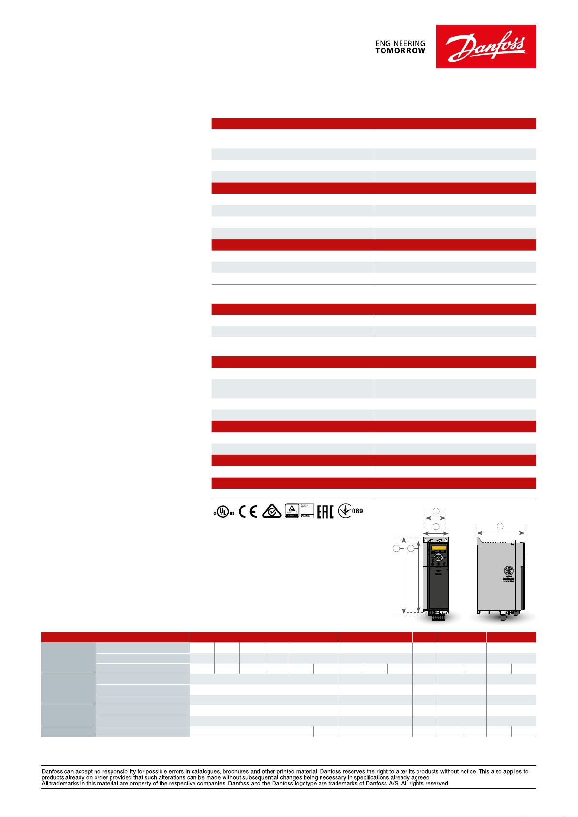
b
B
A a
C
Dimensions and weights
Enclosure IP20 K1 K2 K3 K4 K5
Power size
[kW]
Dimensions
[mm]
Mounting
holes
Weight [kg] IP20
Danfoss Drives, Ulsnaes 1, DK-6300 Graasten, Denmark, Tel. +45 74 88 22 22, Fax +45 74 65 25 80, drives.danfoss.com, E-mail: info@danfoss.com
DKDD.PFP.820.A7.02 © Copyright Danfoss Drives | 2017.06
Single-phase 200-240 V
3-phase 200-240 V 0.37 0.55 0.75 1.1 1.5 2.2 3.7
3-phase 380-480 V 0.37 0.55 0.75 1.1 1.5 2.2 3 4 5.5 7.5 11 15 18.5 22
Height A 210 272.5 272.5 320 410
Width B 75 90 115 135 150
Depth C 168 168 168 245 245
a 198 260 260 297.5 390
b 60 70 90 105 120
0.37 0.55 0.75 1.1 1.5 2.2
2.3 2.5 3.6 4.1 9.4 9.5 12.3 12.5
EtherNet/IP™ and DeviceNet™ are trademarks of ODVA, Inc.
 Loading...