

ENGINEERING TOMORROW
Design Guide
VLT® Midi Drive FC 280
vlt-drives.danfoss.com


Contents Design Guide
Contents
1 Introduction
1.1 Purpose of the Design Guide
1.2 Additional Resources
1.3 Denitions
1.4 Document and Software Version
1.5 Approvals and Certications
1.6 Safety
2 Product Overview
2.1 Enclosure Size Overview
2.2 Electrical Installation
2.2.1 Motor Connection 14
2.2.2 AC Mains Connection 15
2.2.3 Control Terminal Types 16
2.2.4 Wiring to Control Terminals 17
2.3 Control Structures
2.3.1 Control Modes 18
2.3.2 Control Principle 19
2.3.3 Control Structure in VVC
5
5
5
5
8
8
9
10
10
12
18
+
19
2.3.4 Internal Current Control in VVC+ Mode 21
2.3.5 Local (Hand On) and Remote (Auto On) Control 21
2.4 Reference Handling
2.4.1 Reference Limits 23
2.4.2 Scaling of Preset References and Bus References 24
2.4.3 Scaling of Analog and Pulse References and Feedback 24
2.4.4 Dead Band Around Zero 25
2.5 PID Control
2.5.1 Speed PID Control 28
2.5.2 Process PID Control 31
2.5.3 Process Control Relevant Parameters 32
2.5.4 Example of Process PID Control 33
2.5.5 Process Controller Optimization 35
2.5.6 Ziegler Nichols Tuning Method 36
2.6 EMC Emission and Immunity
2.6.1 General Aspects of EMC Emission 36
2.6.2 EMC Emission 38
22
28
36
2.6.3 EMC Immunity 40
2.7 Galvanic Isolation
2.8 Ground Leakage Current
MG07B302 Danfoss A/S © 05/2017 All rights reserved. 1
41
41

Contents
VLT® Midi Drive FC 280
2.9 Brake Functions
2.9.1 Mechanical Holding Brake 42
2.9.2 Dynamic Braking 43
2.9.3 Brake Resistor Selection 43
2.10 Motor Insulation
2.10.1 Sine-wave Filters 44
2.10.2 dU/dt Filters 45
2.11 Smart Logic Controller
2.12 Extreme Running Conditions
2.12.1 Motor Thermal Protection 46
3 Application Examples
3.1 Introduction
3.1.1 Encoder Connection 48
3.1.2 Encoder Direction 48
3.1.3 Closed-loop Drive System 48
3.2 Application Examples
3.2.1 AMA 49
42
44
45
46
48
48
49
3.2.2 Speed 49
3.2.3 Start/Stop 50
3.2.4 External Alarm Reset 51
3.2.5 Motor Thermistor 51
3.2.6 SLC 51
4 Safe Torque O (STO)
5 RS485 Installation and Set-up
5.1 Introduction
5.1.1 Overview 53
5.1.2 Network Connection 53
5.1.3 Hardware Set-up 54
5.1.4 Parameter Settings for Modbus Communication 54
5.1.5 EMC Precautions 54
5.2 FC Protocol
5.2.1 Overview 54
5.2.2 FC with Modbus RTU 55
52
53
53
54
5.3 Network Conguration
5.4 FC Protocol Message Framing Structure
5.4.1 Content of a Character (byte) 55
5.4.2 Telegram Structure 55
5.4.3 Telegram Length (LGE) 55
2 Danfoss A/S © 05/2017 All rights reserved. MG07B302
55
55

Contents Design Guide
5.4.4 Frequency Converter Address (ADR) 56
5.4.5 Data Control Byte (BCC) 56
5.4.6 The Data Field 56
5.4.7 The PKE Field 56
5.4.8 Parameter Number (PNU) 57
5.4.9 Index (IND) 57
5.4.10 Parameter Value (PWE) 57
5.4.11 Data Types Supported by the Frequency Converter 57
5.4.12 Conversion 57
5.4.13 Process Words (PCD) 58
5.5 Examples
5.5.1 Writing a Parameter Value 58
5.5.2 Reading a Parameter Value 58
5.6 Modbus RTU
5.6.1 Prerequisite Knowledge 59
5.6.2 Overview 59
5.6.3 Frequency Converter with Modbus RTU 59
5.7 Network Conguration
5.8 Modbus RTU Message Framing Structure
5.8.1 Introduction 60
5.8.2 Modbus RTU Telegram Structure 60
5.8.3 Start/Stop Field 60
5.8.4 Address Field 60
5.8.5 Function Field 60
5.8.6 Data Field 61
5.8.7 CRC Check Field 61
5.8.8 Coil Register Addressing 61
58
59
59
60
5.8.9 How to Control the Frequency Converter 63
5.8.10 Function Codes Supported by Modbus RTU 63
5.8.11 Modbus Exception Codes 63
5.9 How to Access Parameters
5.9.1 Parameter Handling 63
5.9.2 Storage of Data 64
5.9.3 IND (Index) 64
5.9.4 Text Blocks 64
5.9.5 Conversion Factor 64
5.9.6 Parameter Values 64
5.10 Examples
5.10.1 Read Coil Status (01 hex) 64
5.10.2 Force/Write Single Coil (05 hex) 65
MG07B302 Danfoss A/S © 05/2017 All rights reserved. 3
63
64

Contents
VLT® Midi Drive FC 280
5.10.3 Force/Write Multiple Coils (0F hex) 65
5.10.4 Read Holding Registers (03 hex) 65
5.10.5 Preset Single Register (06 hex) 66
5.10.6 Preset Multiple Registers (10 hex) 66
5.11 Danfoss FC Control Prole
5.11.1 Control Word According to FC Prole (8-10 Protocol = FC Prole) 67
5.11.2 Status Word According to FC Prole (STW) 68
5.11.3 Bus Speed Reference Value 70
6 Type Code and Selection
6.1 Type Code
6.2 Ordering Numbers: Options, Accessories, and Spare Parts
6.3 Ordering Numbers: Brake Resistors
6.3.1 Ordering Numbers: Brake Resistors 10% 73
6.3.2 Ordering Numbers: Brake Resistors 40% 75
6.4 Ordering Numbers: Sine-wave Filters
6.5 Ordering Numbers: dU/dt Filters
6.6 Ordering Numbers: External EMC Filters
7 Specications
7.1 Electrical Data
7.2 Mains Supply
67
71
71
71
73
76
77
77
80
80
83
7.3 Motor Output and Motor Data
7.4 Ambient Conditions
7.5 Cable Specications
7.6 Control Input/Output and Control Data
7.7 Connection Tightening Torques
7.8 Fuses and Circuit Breakers
7.9 Eciency
7.10 Acoustic Noise
7.11 dU/dt Conditions
7.12 Special Conditions
7.12.1 Manual Derating 93
7.12.2 Automatic Derating 95
7.13 Enclosure Sizes, Power Ratings, and Dimensions
Index
83
84
84
85
88
89
90
91
91
92
96
99
4 Danfoss A/S © 05/2017 All rights reserved. MG07B302

Introduction Design Guide
1 Introduction
1.1 Purpose of the Design Guide
This design guide is intended for project and systems
engineers, design consultants, and application and product
specialists. Technical information is provided to understand
the capabilities of the frequency converter for integration
into motor control and monitoring systems. Details
concerning operation, requirements, and recommendations
for system integration are described. Information is
provided for input power characteristics, output for motor
control, and ambient operating conditions for the
frequency converter.
Also included are:
Safety features.
•
Fault condition monitoring.
•
Operational status reporting.
•
Serial communication capabilities.
•
Programmable options and features.
•
Design details such as site requirements, cables, fuses,
control wiring, the size and weight of units, and other
critical information necessary to plan for system integration
are also provided.
Reviewing the detailed product information in the design
stage enables developing a well-conceived system with
optimal functionality and
VLT® is a registered trademark.
Additional Resources
1.2
eciency.
Denitions
1.3
1.3.1 Frequency Converter
Coast
The motor shaft is in free mode. No torque on the motor.
I
VLT,MAX
Maximum output current.
I
VLT,N
Rated output current supplied by the frequency converter.
U
VLT,MAX
Maximum output voltage.
1.3.2 Input
Control commands
Start and stop the connected motor with LCP and digital
inputs.
Functions are divided into 2 groups.
Functions in group 1 have higher priority than functions in
group 2.
Group 1 Precise stop, coast and reset stop, precise stop
and coast stop, quick stop, DC braking, stop, and
[OFF].
Group 2 Start, pulse start, reversing, start reversing, jog,
and freeze output.
Table 1.1 Function Groups
1.3.3 Motor
1 1
Resources available to understand operations and
programming of the frequency converter:
VLT® Midi Drive FC 280 Operating Guide, provides
•
information about the installation, commissioning,
application, and maintenance of the frequency
converter.
VLT® Midi Drive FC 280 Programming Guide,
•
provides information on how to program and
includes complete parameter descriptions.
Supplementary publications and manuals are available
from Danfoss. See drives.danfoss.com/knowledge-center/
technical-documentation/ for listings.
MG07B302 Danfoss A/S © 05/2017 All rights reserved. 5
Motor running
Torque generated on the output shaft and speed from
0 RPM to maximum speed on the motor.
f
JOG
Motor frequency when the jog function is activated (via
digital terminals or bus).
f
M
Motor frequency.
f
MAX
Maximum motor frequency.
f
MIN
Minimum motor frequency.
f
M,N
Rated motor frequency (nameplate data).
I
M
Motor current (actual).
I
M,N
Nominal motor current (nameplate data).
175ZA078.10
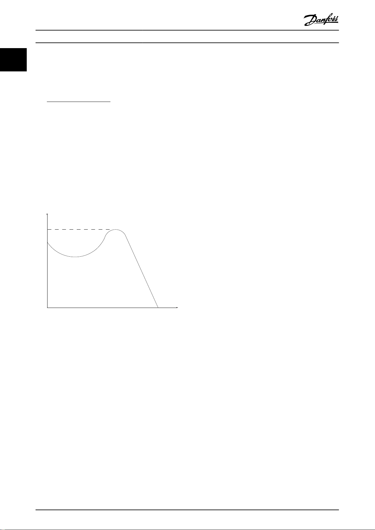
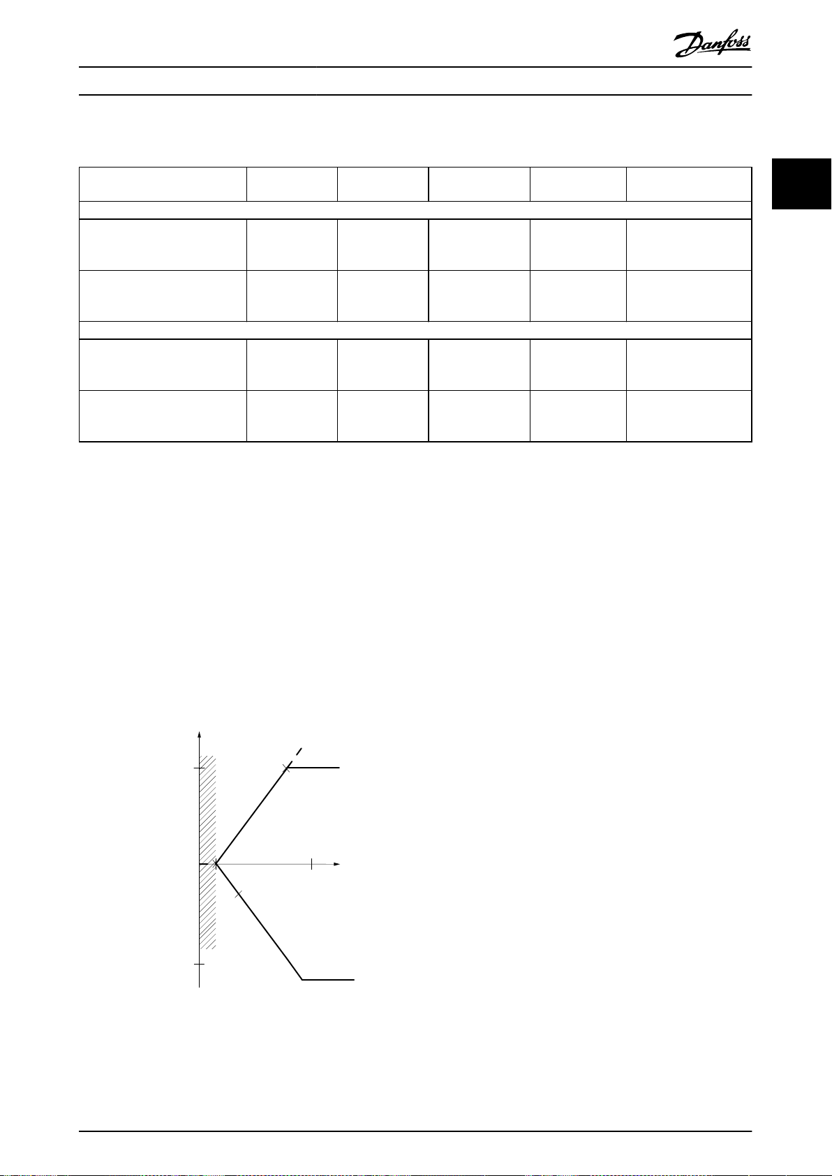
Pull-out
RPM
Torque
Introduction
VLT® Midi Drive FC 280
11
n
M,N
Nominal motor speed (nameplate data).
n
s
Synchronous motor speed.
2 × Parameter 1−23 × 60s
ns=
n
slip
Parameter 1−39
Motor slip.
P
M,N
Rated motor power (nameplate data in kW or hp).
T
M,N
Rated torque (motor).
U
M
Instantaneous motor voltage.
U
M,N
Rated motor voltage (nameplate data).
Break-away torque
Preset reference
A dened preset reference to be set from -100% to +100%
of the reference range. Selection of 8 preset references via
the digital terminals. Selection of 4 preset references via
the bus.
Pulse reference
A pulse frequency signal transmitted to the digital inputs
(terminal 29 or 33).
Ref
MAX
Determines the relationship between the reference input at
100% full scale value (typically 10 V, 20 mA) and the
resulting reference. The maximum reference value is set in
parameter 3-03 Maximum Reference.
Ref
MIN
Determines the relationship between the reference input at
0% value (typically 0 V, 0 mA, 4 mA) and the resulting
reference. The minimum reference value is set in
parameter 3-02 Minimum Reference.
1.3.5 Miscellaneous
Analog inputs
The analog inputs are used for controlling various
functions of the frequency converter.
There are 2 types of analog inputs:
Current input: 0–20 mA and 4–20 mA.
•
Voltage input: 0–10 V DC.
•
Analog outputs
The analog outputs can supply a signal of 0–20 mA, or 4–
20 mA.
Automatic motor adaptation, AMA
Illustration 1.1 Break-away Torque
η
VLT
The eciency of the frequency converter is dened as the
ratio between the power output and the power input.
Start-disable command
A start-disable command belonging to the control
commands in group 1. See Table 1.1 for more details.
Stop command
A stop command belonging to the control commands in
group 1. See Table 1.1 for more details.
1.3.4 References
Analog reference
A signal transmitted to the analog inputs 53 or 54 can be
voltage or current.
Binary reference
A signal transmitted via the serial communication port.
The AMA algorithm determines the electrical parameters
for the connected motor at standstill.
Brake resistor
The brake resistor is a module capable of absorbing the
brake power generated in regenerative braking. This
regenerative brake power increases the DC-link voltage,
and a brake chopper ensures that the power is transmitted
to the brake resistor.
CT characteristics
Constant torque characteristics used for all applications
such as conveyor belts, displacement pumps, and cranes.
Digital inputs
The digital inputs can be used for controlling various
functions of the frequency converter.
Digital outputs
The frequency converter features 2 solid-state outputs that
can supply a 24 V DC (maximum 40 mA) signal.
DSP
Digital signal processor.
6 Danfoss A/S © 05/2017 All rights reserved. MG07B302

Introduction Design Guide
ETR
Electronic thermal relay is a thermal load calculation based
on present load and time. Its purpose is to estimate the
motor temperature.
FC standard bus
Includes RS485 bus with FC protocol or MC protocol. See
parameter 8-30 Protocol.
Initializing
If initializing is carried out (parameter 14-22 Operation
Mode), the frequency converter returns to the default
setting.
Intermittent duty cycle
An intermittent duty rating refers to a sequence of duty
cycles. Each cycle consists of an on-load and an o-load
period. The operation can be either periodic duty or nonperiodic duty.
LCP
The local control panel makes up a complete interface for
control and programming of the frequency converter. The
LCP is detachable. With the installation kit option, the LCP
can be installed up to 3 m (9.8 ft) from the frequency
converter in a front panel.
NLCP
The numerical local control panel interface for control and
programming of the frequency converter. The display is
numerical and the panel is used to show process values.
The NLCP has storing and copy functions.
GLCP
The graphic local control panel interface for control and
programming of the frequency converter. The display is
graphic and the panel is used to show process values. The
GLCP has storing and copy functions.
lsb
Least signicant bit.
msb
Most signicant bit.
MCM
Short for mille circular mil, an American measuring unit for
cable cross-section. 1 MCM = 0.5067 mm2.
On-line/o-line parameters
Changes to on-line parameters are activated immediately
after the data value is changed. To activate changes to o-
line parameters, press [OK].
Process PID
The PID control maintains speed, pressure, and
temperature by adjusting the output frequency to match
the varying load.
PCD
Process control data.
PFC
Power factor correction.
Power cycle
Switch o the mains until the display (LCP) is dark, then
turn power on again.
Power factor
The power factor is the relation between I1 and I
Power factor =
For FC 280 frequency converters,
Power factor =
3xUxI1cosϕ1
3xUxI
I1xcosϕ1
I
RMS
RMS
=
I
RMS
cosϕ
I
1
1 = 1, therefore:
RMS
.
The power factor indicates to which extent the frequency
converter imposes a load on the mains supply.
The lower the power factor, the higher the I
RMS
for the
same kW performance.
I
RMS
=
I
+ I
1
5
+ I
2
+ .. + I
7
2
n
2
2
In addition, a high power factor indicates that the dierent
harmonic currents are low.
The built-in DC coils (T2/T4) and PFC (S2) produce a high
power factor, minimizing the imposed load on the mains
supply.
Pulse input/incremental encoder
An external, digital pulse transmitter used for feeding back
information on motor speed. The encoder is used in
applications where great accuracy in speed control is
required.
RCD
Residual current device.
Set-up
Save parameter settings in 4 set-ups. Change among the 4
parameter set-ups and edit 1 set-up while this set-up is
inactive.
SFAVM
Acronym describing the switching pattern stator uxoriented asynchronous vector modulation.
Slip compensation
The frequency converter compensates for the motor slip by
giving the frequency a supplement that follows the
measured motor load, keeping the motor speed almost
constant.
Smart logic control (SLC)
The SLC is a sequence of user-dened actions executed
when the smart logic controller evaluates the associated
user-dened events as true (Parameter group 13-** Smart
Logic Control).
STW
Status word.
THD
Total harmonic distortion states the total contribution of
harmonic distortion.
Thermistor
A temperature-dependent resistor placed where the
temperature is monitored (frequency converter or motor).
1 1
MG07B302 Danfoss A/S © 05/2017 All rights reserved. 7

Introduction
VLT® Midi Drive FC 280
11
Trip
Trip is a state entered in fault situations. Examples of fault
situations:
The frequency converter is subject to an over
•
voltage.
The frequency converter protects the motor,
•
process, or mechanism.
Restart is prevented until the cause of the fault has
disappeared, and the trip state is canceled by activating
reset or, in some cases, by being programmed to reset
automatically. Do not use trip for personal safety.
Trip lock
Trip lock is a state entered in fault situations when the
frequency converter is protecting itself and requiring
physical intervention. For example, a short circuit on the
output triggers a trip lock. A locked trip can only be
canceled by cutting o mains, removing the cause of the
fault, and reconnecting the frequency converter. Restart is
prevented until the trip state is canceled by activating
reset or, sometimes, by being programmed to reset
automatically. Do not use trip lock for personal safety.
VT characteristics
Variable torque characteristics used for pumps and fans.
+
VVC
If compared with standard voltage/frequency ratio control,
voltage vector control (VVC+) improves the dynamics and
stability, both when the speed reference is changed and in
relation to the load torque.
60° AVM
Refer to the switching pattern 60° asynchronous vector
modulation.
Document and Software Version
1.4
1.5.1 CE Mark
The CE mark (Communauté européenne) indicates that the
product manufacturer conforms to all applicable EU
directives.
The EU directives applicable to the design and
manufacture of frequency converters are:
The Low Voltage Directive.
•
The EMC Directive.
•
The Machinery Directive (for units with an
•
integrated safety function).
The CE mark is intended to eliminate technical barriers to
free trade between the EC and EFTA states inside the ECU.
The CE mark does not regulate the quality of the product.
Technical specications cannot be deduced from the CE
mark.
1.5.2 Low Voltage Directive
Frequency converters are classied as electronic
components and must be CE labeled in accordance with
the Low Voltage Directive. The directive applies to all
electrical equipment in the 50–1000 V AC and the 75–
1500 V DC voltage ranges.
The directive mandates that the equipment design must
ensure the safety and health of people and livestock, and
the preservation of material by ensuring the equipment is
properly installed, maintained, and used as intended.
Danfoss CE labels comply with the Low Voltage Directive,
and Danfoss provides a declaration of conformity at
request.
This manual is regularly reviewed and updated. All
suggestions for improvement are welcome. Table 1.2 shows
the document version and the corresponding software
version.
Edition Remarks
MG07B3
1.5
Frequency converters are designed in compliance with the
directives described in this section.
8 Danfoss A/S © 05/2017 All rights reserved. MG07B302
More information for POWERLINK and
software update.
Table 1.2 Document and Software Version
Approvals and Certications
Software
version
1.3
1.5.3 EMC Directive
Electromagnetic compatibility (EMC) means that electromagnetic interference between pieces of equipment does
not hinder their performance. The basic protection
requirement of the EMC Directive 2014/30/EU states that
devices that generate electromagnetic interference (EMI) or
whose operation could be aected by EMI must be
designed to limit the generation of electromagnetic
interference and shall have a suitable degree of immunity
to EMI when properly installed, maintained, and used as
intended.
A frequency converter can be used as standalone device or
as part of a more complex installation. Devices in either of
these cases must bear the CE mark. Systems must not be
CE marked but must comply with the basic protection
requirements of the EMC directive.

Introduction Design Guide
1.5.4 UL Compliance
UL-listed
Illustration 1.2 UL
Applied standards and compliance for STO
Using STO on terminals 37 and 38 requires fulllment of all
provisions for safety including relevant laws, regulations,
and guidelines. The integrated STO function complies with
the following standards:
IEC/EN 61508:2010, SIL2
•
IEC/EN 61800-5-2:2007, SIL2
•
IEC/EN 62061:2015, SILCL of SIL2
•
EN ISO 13849-1:2015, Category 3 PL d
•
Frequency converters can be subject to regional and/or
national export control regulations.
An ECCN number is used to classify all frequency
converters that are subject to export control regulations.
1 1
The ECCN number is provided in the documents
accompanying the frequency converter.
In case of re-export, it is the responsibility of the exporter
to ensure compliance with the relevant export control
regulations.
Safety
1.6
Frequency converters contain high-voltage components
and have the potential for fatal injury if handled
improperly. Only qualied personnel are allowed to install
and operate the equipment. Do not attempt repair work
without rst removing power from the frequency converter
and waiting the designated duration of time for stored
electrical energy to dissipate.
Refer to the operating instructions shipped with the unit,
and available online for:
Discharge time.
•
Detailed safety instructions and warnings.
•
Strict adherence to safety precautions and notices is
mandatory for safe operation of the frequency converter.
MG07B302 Danfoss A/S © 05/2017 All rights reserved. 9
130BA870.10
130BA809.10
130BA810.10
130BA810.10
130BA810.10
Product Overview
VLT® Midi Drive FC 280
2 Product Overview
22
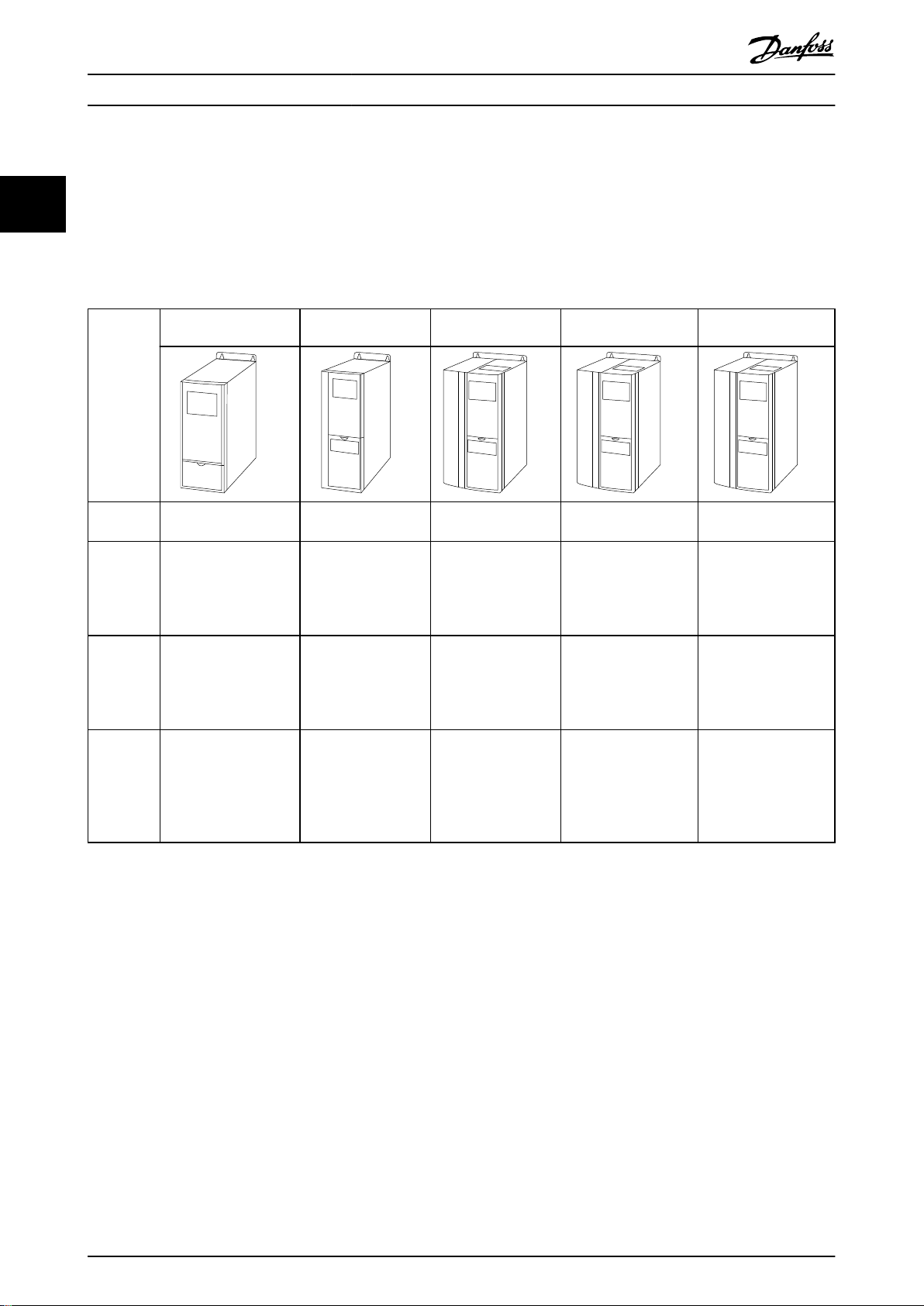
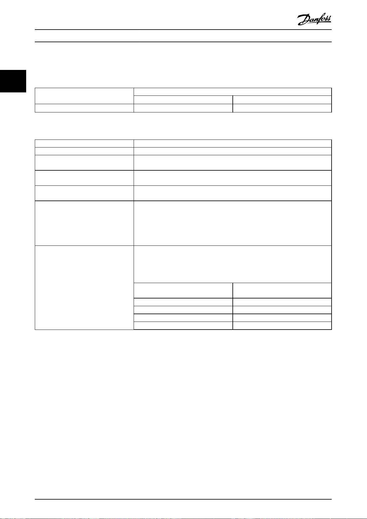
2.1 Enclosure Size Overview
Enclosure size depends on power range. For details about dimensions, refer to chapter 7.13 Enclosure Sizes, Power Ratings,
and Dimensions.
Enclosure
size
Enclosure
protection
Power
range
[kW (hp)]
3-phase
380–480 V
Power
range
[kW (hp)]
3-phase
200–240 V
Power
range
[kW (hp)]
single-
phase
200–240 V
K1 K2 K3 K4 K5
1)
IP20 IP20 IP20 IP20 IP20
0.37–2.2 (0.5–3.0) 3.0–5.5 (5.0–7.5) 7.5 (10) 11–15 (15–20) 18.5–22 (25–30)
0.37–1.5 (0.5–2.0) 2.2 (3.0) 3.7 (5.0) – –
0.37–1.5 (0.5–2.0) 2.2 (3.0) – – –
Table 2.1 Enclosure Sizes
1) IP21 is available for some variants of VLT® Midi Drive FC 280. With IP21 kit options mounted, all power sizes can be IP21.
Enclosure size is used throughout this guide whenever procedures or components dier between frequency converters
based on physical size.
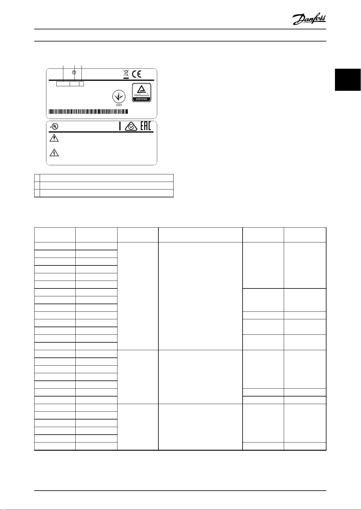
Find the enclosure size using the following steps:
1. Obtain the following information from the type code on the nameplate. Refer to Illustration 2.1.
1a Product group and frequency converter series (characters 1–6), for example FC 280.
1b Power rating (characters 7–10), for example PK37.
1c Voltage rating (phases and mains) (characters 11–12), for example T4.
2. Within Table 2.2,
10 Danfoss A/S © 05/2017 All rights reserved. MG07B302
nd the power rating and voltage rating, and look up the enclosure size of FC 280.
130BF709.10
VLT
MADE IN
DENMARK
T/C: FC-280PK37T4E20H1BXCXXXSXXXXAX
0.37kW 0.5HP
IN: 3x380-480V 50/60Hz, 1.2/1.0A
OUT: 3x0-Vin 0-500Hz, 1.2/1.1A
IP20
P/N: 134U2184 S/N: 000000G000
Midi Drive
www.danfoss.com
CAUTION / ATTENTION:
WARNING / AVERTISSEMENT:
See manual for special condition/mains fuse
Voir manual de conditions speciales/fusibles
Enclosure: See manual
5AF3 E358502 IND.CONT.EQ.
Stored charge, wait 4 min.
Charge r
é
siduelle, attendez 4 min.
R
US LISTED
www.tuv.com
ID 0600000000
Danfoss A/S, 6430 Nordborg, Denmark
1 2 3
Product Overview Design Guide
1 Product group and frequency converter series
2 Power rating
3 Voltage rating (phases and mains)
Illustration 2.1 Using the Nameplate to Find the Enclosure Size
2 2
Power rating in
nameplate
[kW (hp)]
PK37 0.37 (0.5)
PK55 0.55 (0.75)
PK75 0.75 (1.0)
P1K1 1.1 (1.5)
P1K5 1.5 (2.0)
P2K2 2.2 (3.0)
P3K0 3 (4.0)
P4K0 4 (5.0)
P5K5 5.5 (7.5)
P7K5 7.5 (10) K3 K3T4
P11K 11 (15)
P15K 15 (20)
P18K 18.5 (25)
P22K 22 (30)
PK37 0.37 (0.5)
PK55 0.55 (0.75)
PK75 0.75 (1.0)
P1K1 1.1 (1.5)
P1K5 1.5 (2.0)
P2K2 2.2 (3.0) K2 K2T2
P3K7 3.7 (5.0) K3 K3T2
PK37 0.37 (0.5)
PK55 0.55 (0.75)
PK75 0.75 (1.0)
P1K1 1.1 (1.5)
P1K5 1.5 (2.0)
P2K2 2.2 (3.0) K2 K2S2
Table 2.2 Enclosure Size of FC 280
MG07B302 Danfoss A/S © 05/2017 All rights reserved. 11
Power
Voltage rating in
nameplate
Phases and mains voltage Enclosure size
T4 3-phase 380–480 V
T2 3-phase 200–240 V
S2 Single phase 200–240 V
Frequency
converter
K1 K1T4
K2 K2T4
K4 K4T4
K5 K5T4
K1 K1T2
K1 K1S2
Power
input
Switch mode
power supply
Motor
Analog output
interface
(PNP) = Source
(NPN) = Sink
ON = Terminated
OFF = Open
Brake
resistor
91 (L1/N)
92 (L2/L)
93 (L3)
PE
50 (+10 V OUT)
53 (A IN)
2)
54 (A IN)
55 (COM digital/analog I/O)
0/4−20 mA
12 (+24 V OUT)
13 (+24 V OUT)
18 (D IN)
10 V DC
15 mA 100 mA
+ - + -
(U) 96
(V) 97
(W) 98
(PE) 99
(A OUT) 42
(P RS485) 68
(N RS485) 69
(COM RS485) 61
0 V
5 V
S801
0/4−20 mA
RS485
RS485
03
+10 V DC
0−10 V DC
24 V DC
02
01
24 V (NPN)
0 V (PNP)
0 V (PNP)
24 V (NPN)
19 (D IN)
24 V (NPN)
0 V (PNP)
27 (D IN/OUT)
24 V
0 V
0 V (PNP)
24 V (NPN)
29 (D IN)
24 V (NPN)
0 V (PNP)
0 V (PNP)
24 V (NPN)
33 (D IN)
32 (D IN)
38 (STO2)
4)
37 (STO1)
4)
95
P 5-00
21
ON
(+DC/R+) 89
(R-) 81
0−10 V DC
(-DC) 88
RFI
0 V
250 V AC, 3 A
Relay 1
1)
3)
5)
5)
130BE202.18
Product Overview
VLT® Midi Drive FC 280
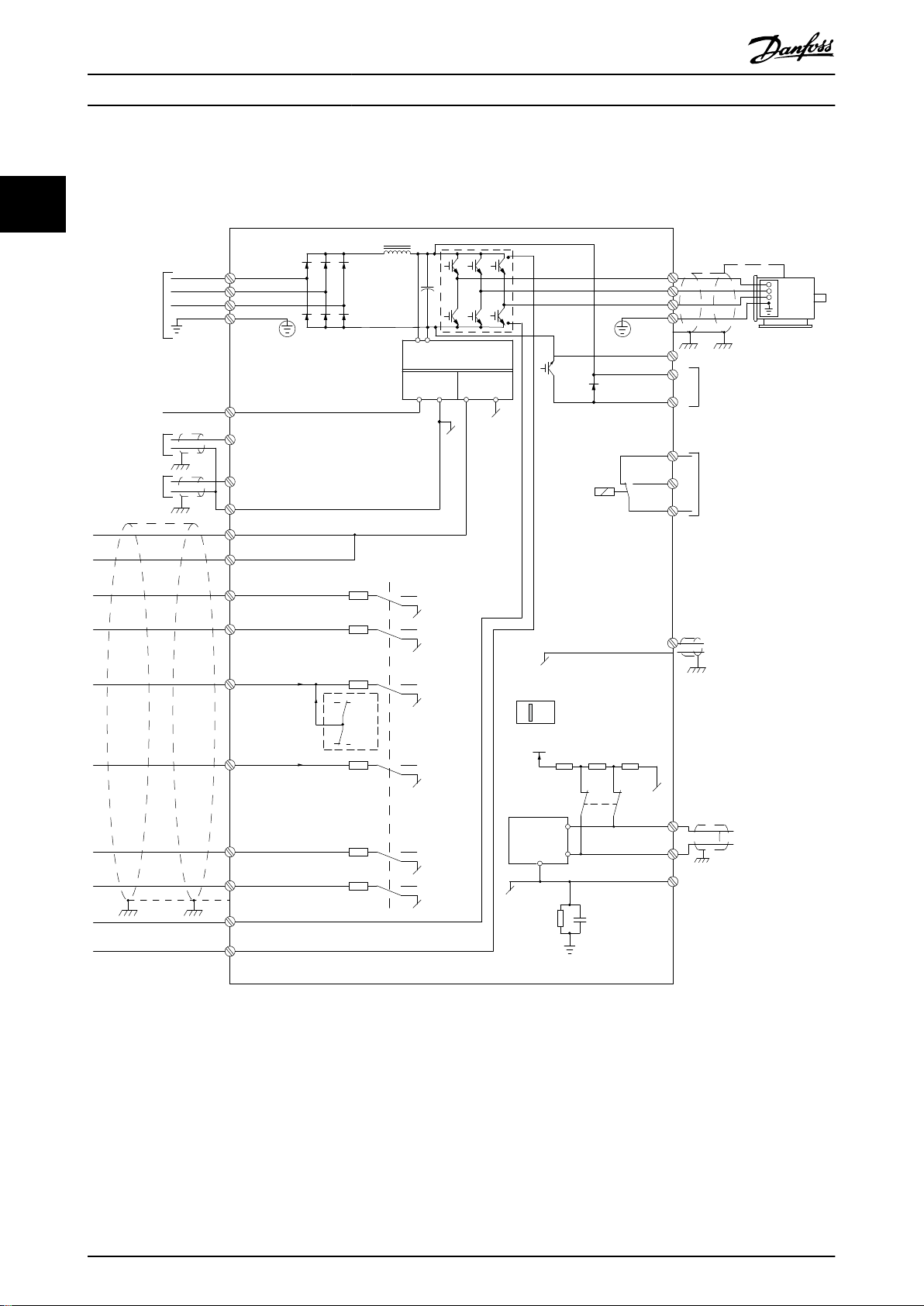
2.2 Electrical Installation
This section describes how to wire the frequency converter.
22
Illustration 2.2 Basic Wiring Schematic Drawing
A = Analog, D = Digital
1) Built-in brake chopper is only available on 3-phase units.
2) Terminal 53 can also be used as digital input.
3) Switch S801 (bus terminal) can be used to enable termination on the RS485 port (terminals 68 and 69).
4) Refer to chapter 4 Safe Torque O (STO) for the correct STO wiring.
5) The S2 (single-phase 200–240 V) frequency converter does not support load sharing application.
12 Danfoss A/S © 05/2017 All rights reserved. MG07B302
130BF228.10
L1
L2
L3
PE
PE
u
v
w
2
1
3
5
16
17
18
14
12
8
7
10
9
4
11
13
4
4
6
15
90
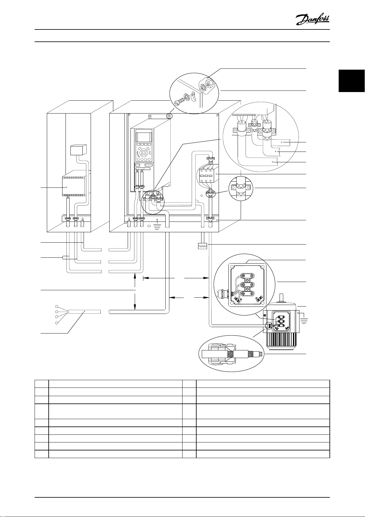
Product Overview Design Guide
2 2
1 PLC 10 Mains cable (unshielded)
2
Minimum 16 mm2 (6 AWG) equalizing cable
3 Control cables 12 Cable insulation stripped
4 Minimum 200 mm (656 ft) between control cables, motor
cables, and mains cables.
5 Mains supply 14 Brake resistor
6 Bare (unpainted) surface 15 Metal box
7 Star washers 16 Connection to motor
8 Brake cable (shielded) 17 Motor
9 Motor cable (shielded) 18 EMC cable gland
Illustration 2.3 Typical Electrical Connection
11 Output contactor, and so on.
13 Common ground busbar. Follow local and national
requirements for cabinet grounding.
MG07B302 Danfoss A/S © 05/2017 All rights reserved. 13
130BD531.10
U
V
W
96
97
98
Product Overview
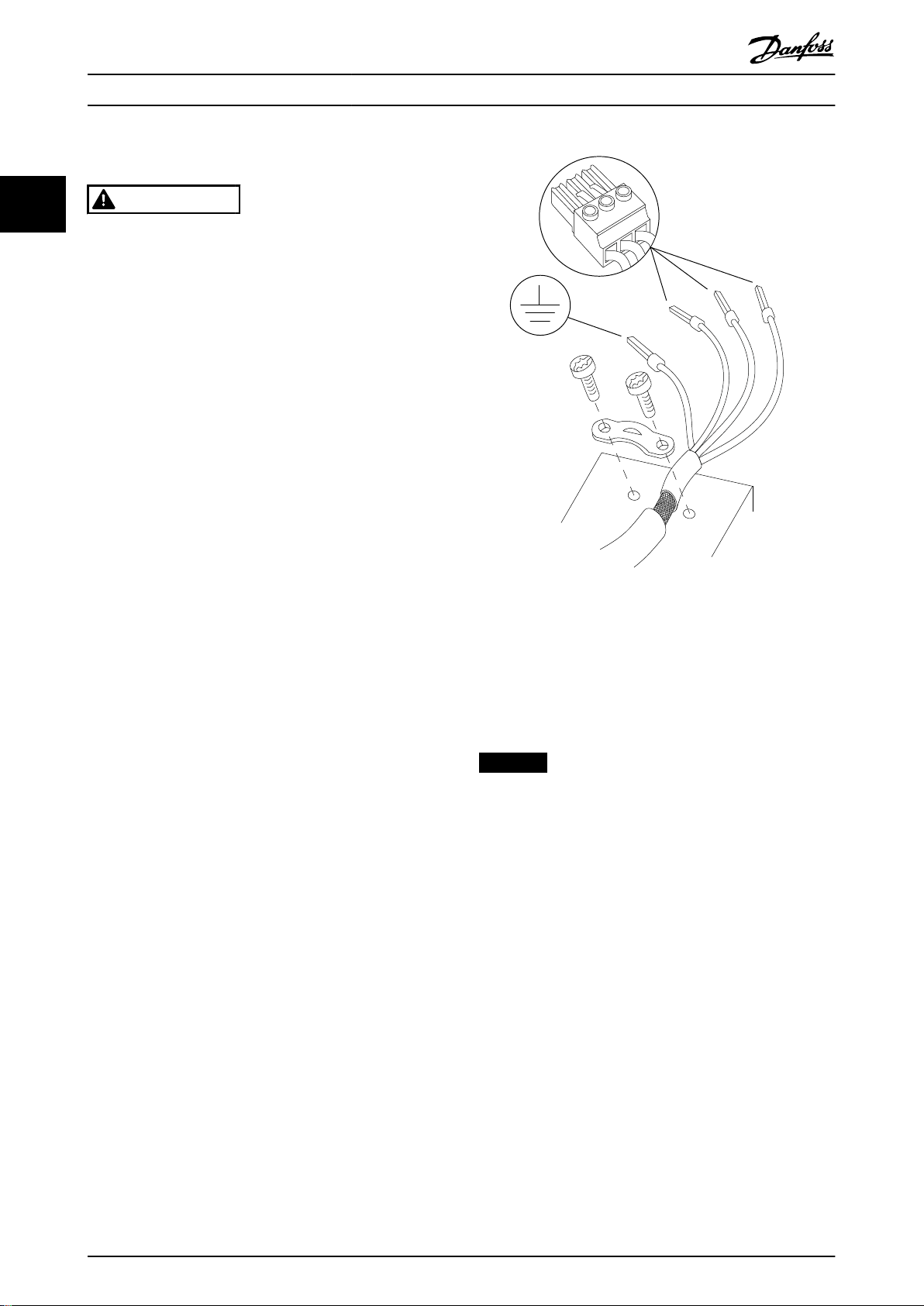
2.2.1 Motor Connection
VLT® Midi Drive FC 280
22
WARNING
INDUCED VOLTAGE
Induced voltage from output motor cables that run
together can charge equipment capacitors, even when
the equipment is turned o and locked out. Failure to
run output motor cables separately or use shielded
cables could result in death or serious injury.
Run output motor cables separately.
•
Use shielded cables.
•
Comply with local and national electrical codes
•
for cable sizes. For maximum cable sizes, see
chapter 7.1 Electrical Data.
Follow motor manufacturer wiring requirements.
•
Motor wiring knockouts or access panels are
•
provided at the base of IP21 (NEMA type 1) units.
Do not wire a starting or pole-changing device
•
(for example Dahlander motor or slip ring
induction motor) between the frequency
converter and the motor.
Procedure
1. Strip a section of the outer cable insulation.
Recommended length is 10–15 mm (0.4–0.6 in).
2. Position the stripped cable under the cable clamp
to establish mechanical xation and electrical
contact between the cable shield and ground.
3. Connect the ground cable to the nearest
grounding terminal in accordance with the
grounding instructions provided in chapter
Grounding in the VLT® Midi Drive FC 280 Operating
Guide. See Illustration 2.4.
4. Connect the 3-phase motor wiring to terminals
96 (U), 97 (V), and 98 (W), as shown in
Illustration 2.4.
5. Tighten the terminals in accordance with the
information provided in chapter 7.7 Connection
Tightening Torques.
Illustration 2.4 Motor Connection
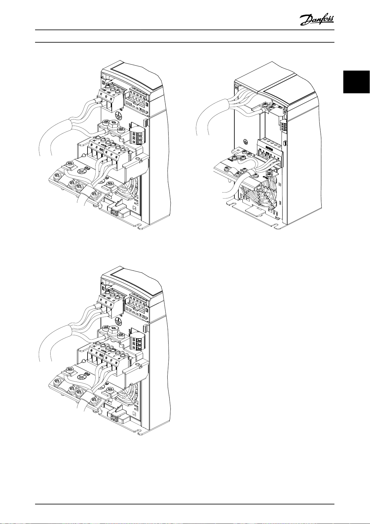
The mains, motor, and grounding connection for singlephase and 3-phase frequency converters are shown in
Illustration 2.5, Illustration 2.6, and Illustration 2.7, respectively. Actual congurations vary with unit types and
optional equipment.
NOTICE
In motors without phase insulation, paper, or other
insulation reinforcement suitable for operation with
voltage supply, use a sine-wave lter on the output of
the frequency converter.
14 Danfoss A/S © 05/2017 All rights reserved. MG07B302
130BE232.11
130BE231.11
130BE804.10
Product Overview Design Guide
2 2
Illustration 2.5 Mains, Motor, and Grounding Connection for
Single-phase Units (K1, K2)
Illustration 2.6 Mains, Motor, and Grounding Connection for 3-
phase Units (K1, K2, K3)
Illustration 2.7 Mains, Motor, and Grounding Connection for 3-
phase Units (K4, K5)
2.2.2 AC Mains Connection
Size the wiring based on the input current of the
•
frequency converter. For maximum wire sizes, see
chapter 7.1 Electrical Data.
Comply with local and national electrical codes
•
for cable sizes.
Procedure
1. Connect the AC input power cables to terminals
N and L for single-phase units (see
Illustration 2.5), or to terminals L1, L2, and L3 for
3-phase units (see Illustration 2.6 and
Illustration 2.7).
2. Depending on the conguration of the
equipment, connect the input power to the
mains input terminals or the input disconnect.
3. Ground the cable in accordance with the
grounding instructions in chapter Grounding in
®
the VLT
4. When supplied from an isolated mains source (IT
mains or oating delta) or TT/TN-S mains with a
grounded leg (grounded delta), ensure that the
RFI lter screw is removed. Removing the RFI
screw prevents damage to the DC link and
reduces ground capacity currents in accordance
with IEC 61800-3 (see Illustration 7.13, the RFI
screw locates on the side of the frequency
converter).
Midi Drive FC 280 Operating Guide.
MG07B302 Danfoss A/S © 05/2017 All rights reserved. 15
130BE212.10
1 2
3
130BE214.10
37 38 12 13 18 19 27 29 32 33 61
42 53 54 50 55
68 69
1
3
2
Product Overview
VLT® Midi Drive FC 280
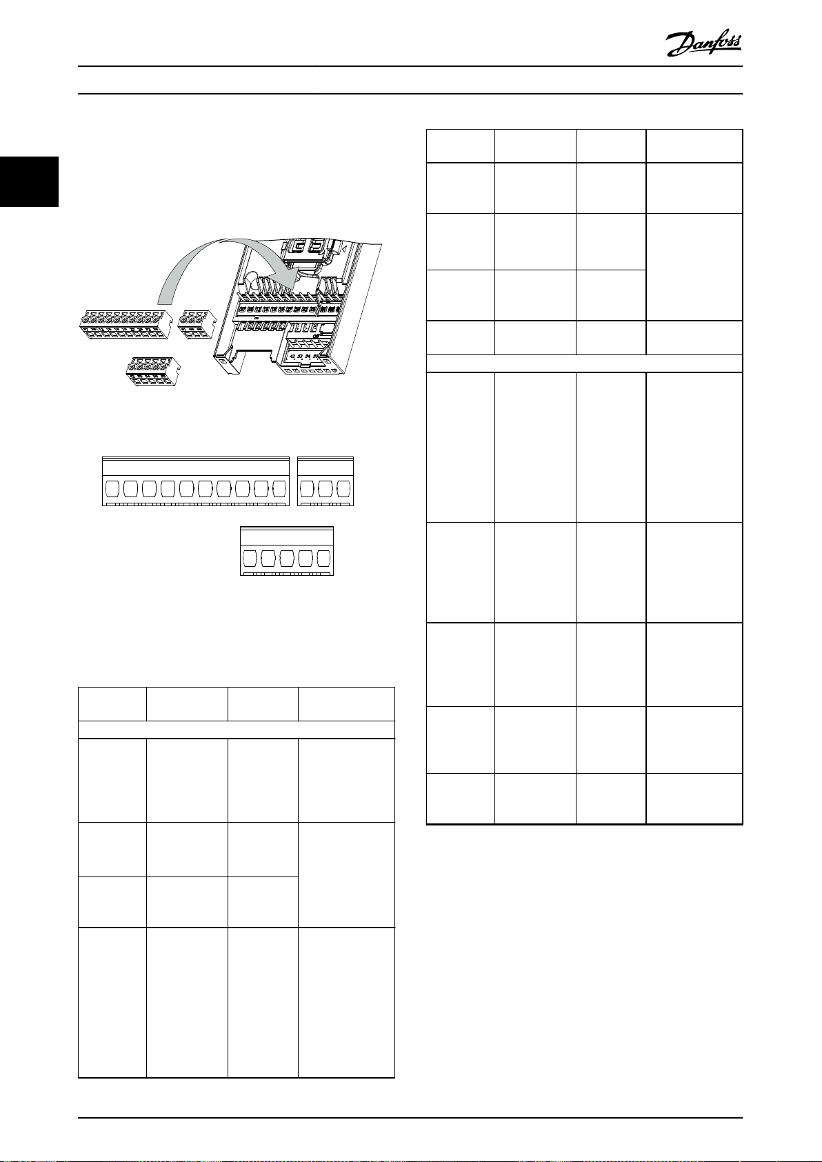
2.2.3 Control Terminal Types
22
Illustration 2.8 shows the removable frequency converter
connectors. Terminal functions and default settings are
summarized in Table 2.3 and Table 2.4.
Illustration 2.8 Control Terminal Locations
Illustration 2.9 Terminal Numbers
See chapter 7.6 Control Input/Output and Control Data for
terminal ratings details.
Terminal Parameter
Digital I/O, pulse I/O, encoder
12, 13 – +24 V DC
Parameter 5-10
18
19
27
Terminal 18
Digital Input
Parameter 5-11
Terminal 19
Digital Input
Parameter 5-01
Terminal 27
Mode
Parameter 5-12
Terminal 27
Digital Input
Parameter 5-30
Terminal 27
Digital Output
Default
setting
[8] Start
[10] Reversing
DI [2] Coast
inverse
DO [0] No
operation
Description
24 V DC supply
voltage. Maximum
output current is
100 mA for all
24 V loads.
Digital inputs.
Selectable for
either digital
input, digital
output, or pulse
output. The
default setting is
digital input.
Terminal Parameter
Parameter 5-13
29
32
33
37, 38 – STO
42
50 – +10 V DC
53
54
55 – –
Table 2.3 Terminal Descriptions - Digital Inputs/Outputs,
Analog Inputs/Outputs
Terminal 29
Digital Input
Parameter 5-14
Terminal 32
Digital Input
Parameter 5-15
Terminal 33
Digital Input
Analog inputs/outputs
Parameter 6-91
Terminal 42
Analog Output
Parameter
group 6-1*
Analog input 53
Parameter
group 6-2*
Analog input 54
Default
setting
[14] Jog Digital input.
[0] No
operation
[0] No
operation
[0] No
operation
–
–
Description
Digital input, 24 V
encoder. Terminal
33 can be used for
pulse input.
Functional safety
inputs.
Programmable
analog output. The
analog signal is 0–
20 mA or 4–
20 mA at a
maximum of
500 Ω. Can also
be congured as
digital outputs.
10 V DC analog
supply voltage.
15 mA maximum
commonly used
for potentiometer
or thermistor.
Analog input. Only
voltage mode is
supported. It can
also be used as
digital input.
Analog input.
Selectable
between voltage
or current mode.
Common for
digital and analog
inputs.
16 Danfoss A/S © 05/2017 All rights reserved. MG07B302

Product Overview Design Guide
Terminal Parameter
Serial communication
61 – –
Parameter
68 (+)
69 (-)
01, 02, 03
group 8-3* FC
port settings
Parameter
group 8-3* FC
port settings
Parameter 5-40
Function Relay
Default
setting
Relays
[1] Control
Ready
–
–
Description
Integrated RC lter
for cable shield.
ONLY for
connecting the
shield when
experiencing EMC
problems.
RS485 interface. A
control card switch
is provided for
termination
resistance.
Form C relay
output. These
relays are in
various locations
depending on the
frequency
converter congu-
ration and size.
Usable for AC or
DC voltage and
resistive or
inductive loads.
2.2.4 Wiring to Control Terminals
Control terminal connectors can be unplugged from the
frequency converter for ease of installation, as shown in
Illustration 2.8.
For details about STO wiring, refer to chapter 4 Safe Torque
O (STO).
NOTICE
Keep control cables as short as possible and separate
them from high-power cables to minimize interference.
1. Loosen the screws for the terminals.
2. Insert sleeved control cables into the slots.
3. Fasten the screws for the terminals.
4. Ensure that the contact is rmly established and
not loose. Loose control wiring can be the source
of equipment faults or less than optimal
operation.
See chapter 7.5 Cable Specications for control terminal
cable sizes and chapter 3 Application Examples for typical
control cable connections.
2 2
Table 2.4 Terminal Descriptions - Serial Communication
MG07B302 Danfoss A/S © 05/2017 All rights reserved. 17

Product Overview
VLT® Midi Drive FC 280
2.3 Control Structures
A frequency converter recties AC voltage from mains into
22
DC voltage. Then the DC voltage is converted into an AC
current with a variable amplitude and frequency.
The motor is supplied with variable voltage/current and
frequency, enabling
phased standard AC motors and permanent magnet
synchronous motors.
innitely variable speed control of 3-
Speed/torque reference
The reference to these controls can be either a single
reference or the sum of various references including
relatively scaled references. Reference handling is explained
in detail in chapter 2.4 Reference Handling.
Process control
There are 2 types of process control:
2.3.1 Control Modes
The frequency converter controls either the speed or the
torque on the motor shaft. The frequency converter also
controls the process for some applications which use
process data as reference or feedback, for example,
temperature and pressure. Setting parameter 1-00 Congu-
ration Mode determines the type of control.
Speed control
There are 2 types of speed control:
Speed open-loop control, which does not require
•
any feedback from the motor (sensorless).
Speed closed-loop PID control, which requires a
•
speed feedback to an input. A properly optimized
speed closed-loop control has higher accuracy
than a speed open-loop control.
Select which input to use as speed PID feedback in
parameter 7-00 Speed PID Feedback Source.
Torque control
The torque control function is used in applications where
the torque on motor output shaft controls the application
as tension control. Select [2] Torque closed loop or [4]
Torque open loop in parameter 1-00 Conguration Mode.
Torque setting is done by setting an analog, digital, or buscontrolled reference. When running torque control, it is
recommended to run a full AMA procedure, because
correct motor data is important in achieving optimal
performance.
works for 2 directions. The torque is calculated
from the internal current measurement in the
frequency converter.
Process closed-loop control, which runs speed
•
open-loop to control the motor internally, is a
basic process PID controller.
Extended PID speed open-loop control, which
•
also runs speed open-loop to control the motor
internally, extends the function of the basic
process PID controller by adding more functions.
For example, feed forward control, clamping,
reference/feedback lter, and gain scaling.
Closed loop in VVC+ mode. This function is used
•
in applications with low to medium dynamic
variation of shaft and oers excellent
performance in all 4 quadrants and at all motor
speeds. The speed feedback signal is mandatory.
Ensure that the encoder resolution is at least
1024 PPR, and the shield cable of the encoder is
properly grounded, because the accuracy of the
speed feedback signal is important. Tune
parameter 7-06 Speed PID Lowpass Filter Time to
get the best speed feedback signal.
Open loop in VVC+ mode. The function is used in
•
mechanically robust applications, but the
accuracy is limited. Open-loop torque function
18 Danfoss A/S © 05/2017 All rights reserved. MG07B302
130BD974.10
L2 92
L1 91
L3 93
M
U 96
V 97
W 98
RFI switch
Inrush
R+
82
Load sharing -
88(-)
R81
Brake resistor
Load sharing +
89(+)
+
_
+
_
S
S
Cong. mode
Ref.
Process
P 1-00
High
+f max.
Low
-f max.
P 4-12
Motor speed
low limit (Hz)
P 4-14
Motor speed
high limit (Hz)
Motor
controller
Ramp
Speed
PID
P 7-20 Process feedback
1 source
P 7-22 Process feedback
2 source
P 7-00 Speed PID
feedback source
P 1-00
Cong. mode
P 4-19
Max. output freq.
-f max.
Motor
controller
P 4-19
Max. output freq.
+f max.
P 3-**
P 7-0*
130BD371.10
Product Overview Design Guide
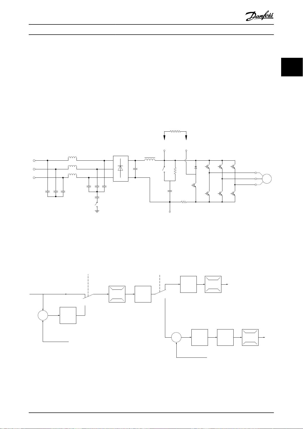
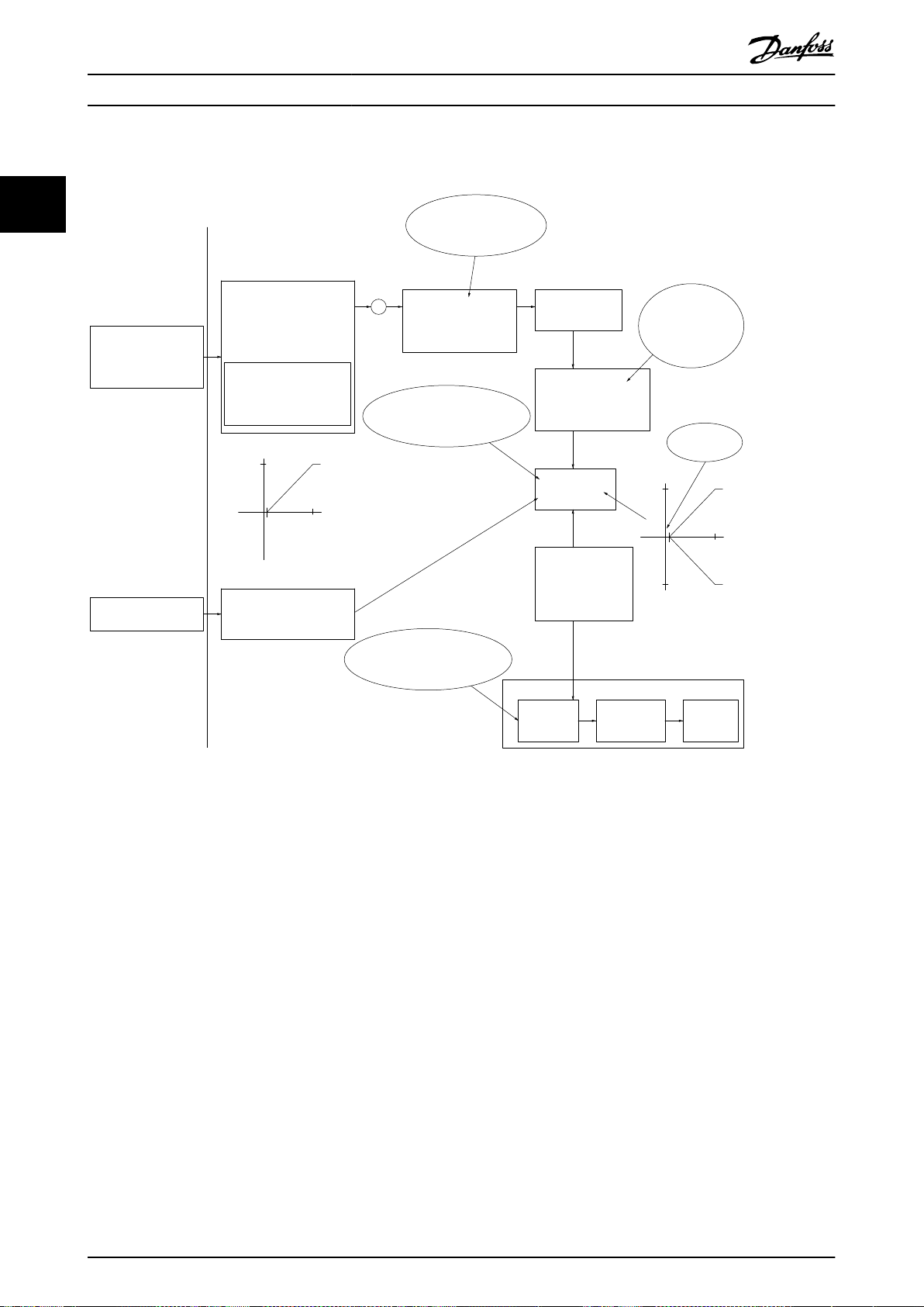
2.3.2 Control Principle
VLT® Midi Drive FC 280 is a general-purpose frequency converter for variable speed applications. The control principle is
based on VVC+.
FC 280 frequency converters can handle asynchronous motors and permanent magnet synchronous motors up to 22 kW
(30 hp).
The current-sensing principle in FC 280 frequency converters is based on the current measurement by a resistor in the DC
link. The ground fault protection and short circuit behavior are handled by the same resistor.
2 2
Illustration 2.10 Control Diagram
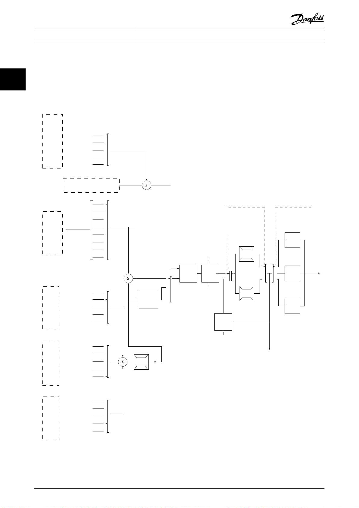
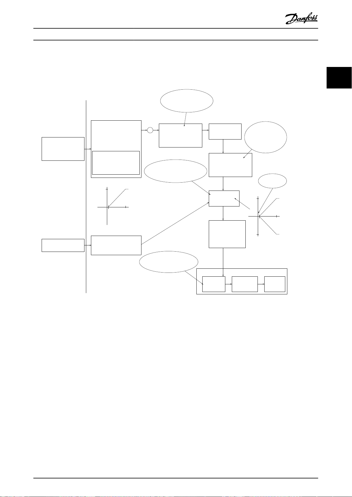
2.3.3
Control Structure in VVC
Illustration 2.11 Control Structure in VVC+ Open-loop Congurations and Closed-loop Congurations
In the conguration shown in Illustration 2.11, parameter 1-01 Motor Control Principle is set to [1] VVC+ and
parameter 1-00 Conguration Mode is set to [0] Speed open loop. The resulting reference from the reference handling system
MG07B302 Danfoss A/S © 05/2017 All rights reserved. 19
+

Product Overview
is received and fed through the ramp limitation and speed limitation before being sent to the motor control. The output of
the motor control is then limited by the maximum frequency limit.
VLT® Midi Drive FC 280
22
If parameter 1-00 Conguration Mode is set to [1] Speed closed loop, the resulting reference is passed from the ramp
limitation and speed limitation into a speed PID control. The speed PID control parameters are in parameter group 7-0*
Speed PID Ctrl. The resulting reference from the speed PID control is sent to the motor control limited by the frequency limit.
Select [3] Process in parameter 1-00
pressure in the controlled application. The process PID parameters are in parameter groups 7-2* Process Ctrl. Feedb and 7-3*
Process PID Ctrl.
Conguration Mode to use the process PID control for closed-loop control of speed or
20 Danfoss A/S © 05/2017 All rights reserved. MG07B302

130BP046.10
Hand
on
O
Auto
on
Reset
Hand
On
Off
Reset
Auto
On
130BB893.10
Product Overview Design Guide
2.3.4
Internal Current Control in VVC
+
Mode
The frequency converter features an integral current limit
control. This feature is activated when the motor current,
and thus the torque, is higher than the torque limits set in
parameter 4-16 Torque Limit Motor Mode,
parameter 4-17 Torque Limit Generator Mode, and
parameter 4-18 Current Limit.
When the frequency converter is at the current limit during
motor operation or regenerative operation, the frequency
converter tries to get below the preset torque limits as
quickly as possible without losing control of the motor.
2.3.5 Local (Hand On) and Remote (Auto
On) Control
Operate the frequency converter manually via the local
control panel (graphic LCP or numerical LCP) or remotely
via analog/digital inputs or eldbus.
Start and stop the frequency converter by pressing the
[Hand On] and [Reset] keys on the LCP. Set-up is required
via the following parameters:
2 2
Parameter 0-40 [Hand on] Key on LCP.
•
Parameter 0-44 [O/Reset] Key on LCP.
•
Parameter 0-42 [Auto on] Key on LCP.
•
Reset alarms via the [Reset] key or via a digital input, when
the terminal is programmed to Reset.
Illustration 2.12 GLCP Control Keys
Illustration 2.13 NLCP Control Keys
Local reference forces the
loop, independent of the setting in parameter 1-00 Congu-
ration Mode.
conguration mode to open
Local reference is restored when the frequency converter
powers down.
MG07B302 Danfoss A/S © 05/2017 All rights reserved. 21
No function
Analog ref.
Pulse ref.
Local bus ref.
Preset relative ref.
Preset ref.
Local bus ref.
No function
Analog ref.
Pulse ref.
Analog ref.
Pulse ref.
Local bus ref.
No function
Local bus ref.
Pulse ref.
No function
Analog ref.
Input command:
Catch up/ slow down
Catchup Slowdown
value
Freeze ref./Freeze output
Speed up/ speed down
ref.
Remote
Ref. in %
-max ref./
+max ref.
Scale to
Hz
Scale to
Nm
Scale to
process
unit
Relative
X+X*Y
/100
DigiPot
DigiPot
DigiPot
max ref.
min ref.
DigiPot
D1
P 5-1x(15)
Preset '1'
External '0'
Process
Torque
Speed
open/closed loop
(1)
(2)
(3)
(4)
(5)
(6)
(7)
(0)
(0)
(1)
Relative scaling ref.
P 3-18
Ref.resource 1
P 3-15
Ref. resource 2
P 3-16
Ref. resource 3
P 3-17
200%
-200%
Y
X
-100%
100%
%
%
Ref./feedback range
P 3-00
Conguration mode
P 1-00
P 3-14
±100%
130BD374.10
P 16-01
P 16-02
P 3-12
P 5-1x(21)/P 5-1x(22)
P 5-1x(28)/P 5-1x(29)
P 5-1x(19)/P 5-1x(20)
P 3-04
Freeze ref.
&
increase/
decrease
ref.
Catch up/
slow
down
P 3-10
Product Overview
VLT® Midi Drive FC 280
2.4 Reference Handling
Local reference
22
The local reference is active when the frequency converter is operated with [Hand On] active. Adjust the reference by [▲]/[▼]
and [◄/[►].
Remote reference
The reference handling system for calculating the remote reference is shown in Illustration 2.14.
Illustration 2.14 Remote Reference
22 Danfoss A/S © 05/2017 All rights reserved. MG07B302

Resulting reference
Sum of all
references
Forward
Reverse
P 3-00 Reference Range= [0] Min-Max
130BA184.10
-P 3-03
P 3-03
P 3-02
-P 3-02
P 3-00 Reference Range =[1]-Max-Max
Resulting reference
Sum of all
references
-P 3-03
P 3-03
130BA185.10
Product Overview Design Guide
The remote reference is calculated once in every scan
interval and initially consists of 2 types of reference
inputs:
1. X (the external reference): A sum (see
parameter 3-04 Reference Function) of up to 4
externally selected references, comprising any
combination (determined by the setting of
parameter 3-15 Reference 1 Source,
parameter 3-16 Reference 2 Source, and
parameter 3-17 Reference 3 Source) of a xed
preset reference (parameter 3-10 Preset Reference),
variable analog references, variable digital pulse
references, and various eldbus references in any
unit the frequency converter is monitoring ([Hz],
[RPM], [Nm], and so on).
2. Y (the relative reference): A sum of 1 xed preset
reference (parameter 3-14 Preset Relative Reference)
and 1 variable analog reference
(parameter 3-18 Relative Scaling Reference
Resource) in [%].
The 2 types of reference inputs are combined in the
following formula:
Remote reference=X+X*Y/100%.
If relative reference is not used, set parameter 3-18 Relative
Scaling Reference Resource to [0] No function and
parameter 3-14 Preset Relative Reference to 0%. The digital
inputs on the frequency converter can activate both the
catch up/slow down function and the freeze reference
function. The functions and parameters are described in
the VLT® Midi Drive FC 280 Programming Guide.
The scaling of analog references is described in parameter
groups 6-1* Analog Input 53 and 6-2* Analog Input 54, and
the scaling of digital pulse references is described in
parameter group 5-5* Pulse Input.
Reference limits and ranges are set in parameter group 3-0*
Reference Limits.
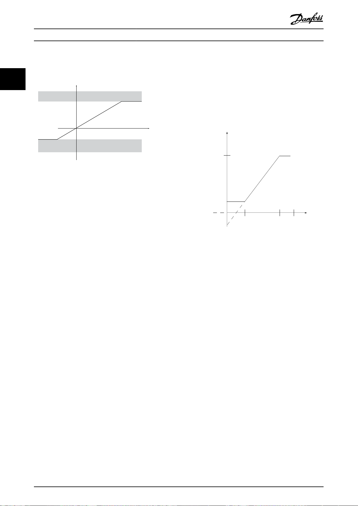
2.4.1 Reference Limits
Parameter 3-00 Reference Range, parameter 3-02 Minimum
Reference, and parameter 3-03 Maximum Reference dene
the allowed range of the sum of all references. The sum of
all references is clamped when necessary. The relation
between the resulting reference (after clamping) and the
sum of all references are shown in Illustration 2.15 and
Illustration 2.16.
Illustration 2.15 Sum of All References When Reference Range
is Set to 0
2 2
MG07B302 Danfoss A/S © 05/2017 All rights reserved. 23
Illustration 2.16 Sum of All References When Reference Range
is Set to 1
The value of parameter 3-02 Minimum Reference cannot be
set to less than 0, unless parameter 1-00 Conguration
Mode is set to [3] Process. In that case, the following
relations between the resulting reference (after clamping)
and the sum of all references are as shown in
Illustration 2.17.
130BA186.11
P 3-03
P 3-02
Sum of all
references
P 3-00 Reference Range= [0] Min to Max
Resulting reference
Resource output
[Hz]
Resource input
Terminal X
high
High reference/
feedback value
130BD431.10
8
[V]
50
10
P1
P2
10
Low reference/
feedback value
Product Overview
VLT® Midi Drive FC 280
2.4.3 Scaling of Analog and Pulse
References and Feedback
22
References and feedback are scaled from analog and pulse
inputs in the same way. The only dierence is that a
reference above or below the specied minimum and
maximum endpoints (P1 and P2 in Illustration 2.18) are
clamped while feedbacks above or below are not.
Illustration 2.17 Sum of All References When Minimum
Reference is Set to a Minus Value
2.4.2 Scaling of Preset References and Bus
References
Preset references are scaled according to the following
rules:
When parameter 3-00 Reference Range is set to [0]
•
Min–Max, 0% reference equals 0 [unit] where unit
can be any unit, for example RPM, m/s, and bar.
100% reference equals the maximum (absolute
value of parameter 3-03 Maximum Reference,
absolute value of parameter 3-02 Minimum
Reference).
When parameter 3-00 Reference Range is set to [1]
•
-Max–+Max, 0% reference equals 0 [unit], and
100% reference equals maximum reference.
Bus references are scaled according to the following
rules:
When parameter 3-00 Reference Range is set to [0]
•
Min–Max, 0% reference equals minimum
reference and 100% reference equals maximum
reference.
When parameter 3-00 Reference Range is set to [1]
•
-Max–+Max, -100% reference equals -maximum
reference, and 100% reference equals maximum
reference.
Illustration 2.18 Minimum and Maximum Endpoints
24 Danfoss A/S © 05/2017 All rights reserved. MG07B302
Resource output
[Hz] or “No unit”
Resource input
[mA]
Quadrant 2
Quadrant 3
Quadrant 1
Quadrant 4
Terminal X high
Low reference/feedback
value
High reference/feedback
value
1
-50
165020
P1
P2
0
130BD446.10
forward
reverse
Terminal low
Product Overview Design Guide
The endpoints P1 and P2 are dened in Table 2.5 depending on the choice of input.
Input Analog 53
voltage mode
P1=(Minimum input value, minimum reference value)
Minimum reference value Parameter 6-14 Te
rminal 53 Low
Ref./Feedb. Value
Minimum input value Parameter 6-10 Te
rminal 53 Low
Voltage [V]
P2=(Maximum input value, maximum reference value)
Maximum reference value Parameter 6-15 Te
rminal 53 High
Ref./Feedb. Value
Maximum input value Parameter 6-11 Te
rminal 53 High
Voltage [V]
Table 2.5 P1 and P2 Endpoints
Analog 54
voltage mode
Parameter 6-24 Te
rminal 54 Low
Ref./Feedb. Value
Parameter 6-20 Te
rminal 54 Low
Voltage [V]
Parameter 6-25 Te
rminal 54 High
Ref./Feedb. Value
Parameter 6-21 Te
rminal 54 High
Voltage [V]
Analog 54
current mode
Parameter 6-24 Ter
minal 54 Low Ref./
Feedb. Value
Parameter 6-22 Ter
minal 54 Low
Current [mA]
Parameter 6-25 Ter
minal 54 High Ref./
Feedb. Value
Parameter 6-23 Ter
minal 54 High
Current [mA]
Pulse input 29 Pulse input 33
Parameter 5-52 Ter
m. 29 Low Ref./
Feedb. Value
Parameter 5-50 Ter
m. 29 Low
Frequency [Hz]
Parameter 5-53 Ter
m. 29 High Ref./
Feedb. Value
Parameter 5-51 Ter
m. 29 High
Frequency [Hz]
Parameter 5-57 Term. 33
Low Ref./Feedb. Value
Parameter 5-55 Term. 33
Low Frequency [Hz]
Parameter 5-58 Term. 33
High Ref./Feedb. Value
Parameter 5-56 Term. 33
High Frequency [Hz]
2.4.4 Dead Band Around Zero
Sometimes, the reference (in rare cases also the feedback) should have a dead band around 0 to ensure that the machine is
stopped when the reference is near 0.
2 2
To make the dead band active and to set the amount of dead band, do the following:
P1 or P2
Set either the minimum reference value (see Table 2.5 for relevant parameter) or maximum reference value at 0. In
•
other words, either P1 or P2 must be on the X-axis in Illustration 2.19.
Ensure that both points dening the scaling graph are in the same quadrant.
•
denes the size of the dead band as shown in Illustration 2.19.
MG07B302 Danfoss A/S © 05/2017 All rights reserved. 25
Illustration 2.19 Size of Dead Band
20
1
10
V
V
20
1
10
-20
130BD454.10
+
Analog input 53
Low reference 0 Hz
High reference 20 Hz
Low voltage 1 V
High voltage 10 V
Ext. source 1
Range:
0.0% (0 Hz)
100.0% (20 Hz)
100.0% (20 Hz)
Ext. reference
Range:
0.0% (0 Hz)
20 Hz 10V
Ext. Reference
Absolute
0 Hz 1 V
Reference
algorithm
Reference
100.0% (20 Hz)
0.0% (0 Hz)
Range:
Limited to:
0%- +100%
(0 Hz- +20 Hz)
Limited to: -200%- +200%
(-40 Hz- +40 Hz)
Reference is scaled
according to min
max reference giving a
speed.!!!
Scale to
speed
+20 Hz
-20 Hz
Range:
Speed
setpoint
Motor
control
Range:
-8 Hz
+8 Hz
Motor
Digital input 19
Low No reversing
High Reversing
Limits Speed Setpoint
according to min max speed.!!!
Motor PID
Hz
Hz
Dead band
Digital input
General Reference
parameters:
Reference Range: Min - Max
Minimum Reference: 0 Hz (0,0%)
Maximum Reference: 20 Hz (100,0%)
General Motor
parameters:
Motor speed direction:Both directions
Motor speed Low limit: 0 Hz
Motor speed high limit: 8 Hz
Product Overview
VLT® Midi Drive FC 280
Case 1: Positive reference with dead band, digital input to trigger reverse, part I
Illustration 2.20 shows how reference input with limits inside minimum to maximum limits clamps.
22
Illustration 2.20 Clamping of Reference Input with Limits inside Minimum to Maximum
26 Danfoss A/S © 05/2017 All rights reserved. MG07B302
+
30 Hz
1
10
20 Hz
1
10
130BD433.11
-20 Hz
V
V
Analog input 53
Low reference 0 Hz
High reference 20 Hz
Low voltage 1 V
High voltage 10 V
Ext. source 1
Range:
0.0% (0 Hz)
150.0% (30 Hz)
150.0% (30 Hz)
Ext. reference
Range:
0.0% (0 Hz)
30 Hz 10 V
Ext. Reference
Absolute
0 Hz 1 V
Reference
algorithm
Reference
100.0% (20 Hz)
0.0% (0 Hz)
Range:
Limited to:
-100%- +100%
(-20 Hz- +20 Hz)
Limited to: -200%- +200%
(-40 Hz- +40 Hz)
Reference is scaled
according to
max reference giving a
speed.!!!
Scale to
speed
+20 Hz
-20 Hz
Range:
Speed
setpoint
Motor
control
Range:
–10 Hz
+10 Hz
Motor
Digital input 19
Low No reversing
High Reversing
Limits Speed Setpoint
according to min max speed.!!!
Motor PID
Dead band
Digital input
General Reference
parameters:
Reference Range: -Max - Max
Minimum Reference: Don't care
Maximum Reference: 20 Hz (100.0%)
General Motor
parameters:
Motor speed direction: Both directions
Motor speed Low limit: 0 Hz
Motor speed high limit: 10 Hz
Product Overview Design Guide
Case 2: Positive reference with dead band, digital input to trigger reverse, part II
Illustration 2.21 shows how reference input with limits outside -maximum to +maximum limits clamps to the input low and
high limits before adding to external reference, and how the external reference is clamped to -maximum to +maximum by
the reference algorithm.
2 2
Illustration 2.21 Clamping of Reference Input with Limits outside -Maximum to +Maximum
MG07B302 Danfoss A/S © 05/2017 All rights reserved. 27
Product Overview
VLT® Midi Drive FC 280
2.5 PID Control
2.5.1 Speed PID Control
22
Parameter 1-00 Conguration Mode
[1] Speed closed loop
Table 2.6 Control Congurations, Active Speed Control
1) Not available indicates that the
Parameter Description of function
Parameter 7-00 Speed PID Feedback Source Select from which input the speed PID gets its feedback.
Parameter 7-02 Speed PID Proportional Gain The higher the value, the quicker the control. However, too high a value may lead to
Parameter 7-03 Speed PID Integral Time Eliminates steady state speed error. Lower values mean quicker reaction. However, too low
Parameter 7-04 Speed PID Dierentiation Time Provides a gain proportional to the rate of change of the feedback. A setting of 0 disables
Parameter 7-05 Speed PID Di. Gain Limit If there are quick changes in reference or feedback in a given application, which means
Parameter 7-06 Speed PID Lowpass Filter Time A low-pass lter that dampens oscillations on the feedback signal and improves steady
specic mode is not available at all.
Parameter 1-01 Motor Control Principle
U/f
Not available
oscillations.
a value may lead to oscillations.
the dierentiator.
that the error changes swiftly, the dierentiator may soon become too dominant. This is
because it reacts to changes in the error. The quicker the error changes, the stronger the
dierentiator gain is. The dierentiator gain can thus be limited to allow setting of the
reasonable dierentiation time for slow changes and a suitably quick gain for quick
changes.
state performance. However, too long a lter time deteriorates the dynamic performance of
the speed PID control.
Practical settings of parameter 7-06 Speed PID Lowpass Filter Time taken from the number of
pulses per revolution on from encoder (PPR):
Encoder PPR Parameter 7-06 Speed PID Lowpass Filter
512 10 ms
1024 5 ms
2048 2 ms
4096 1 ms
1)
VVC
Active
Time
+
Table 2.7 Speed Control Parameters
28 Danfoss A/S © 05/2017 All rights reserved. MG07B302

M
3
96 97 9998
91 92 93 95
50
12
L1 L2L1PEL3
W PEVU
F1
L2
L3
N
PE
18
53
27
55
32
33
24 Vdc
130BD372.11
Product Overview Design Guide
Example of programming the speed control
In this example, the speed PID control is used to maintain a constant motor speed regardless of the changing load on the
motor. The required motor speed is set via a potentiometer connected to terminal 53. The speed range is 0–1500 RPM
corresponding to 0–10 V over the potentiometer. A switch connected to terminal 18 controls starting and stopping. The
speed PID monitors the actual RPM of the motor by using a 24 V (HTL) incremental encoder as feedback. The feedback
sensor is an encoder (1024 pulses per revolution) connected to terminals 32 and 33. The pulse frequency range to terminals
32 and 33 is 4 Hz–32 kHz.
2 2
Illustration 2.22 Speed Control Programming
Follow the steps in Table 2.8 to program the speed control (see explanation of settings in the programming guide)
In Table 2.8, it is assumed that all other parameters and switches remain at their default setting.
Function Parameter number Setting
1) Make sure that the motor runs properly. Do the following:
Set the motor parameters using the data on the
nameplate.
Perform an AMA. Parameter 1-29 Automatic
2) Check that the motor is running and that the encoder is attached properly. Do the following:
Press [Hand On]. Check that the motor is running and note
the rotation direction (referred to as the positive direction).
3) Make sure that the frequency converter limits are set to safe values:
Set acceptable limits for the references. Parameter 3-02 Minimum
Check that the ramp settings are within frequency
converter capabilities and allowed application operating
specications.
Parameter group 1-2*
As specied by motor nameplate.
Motor Data
[1] Enable complete AMA
Motor Adaption (AMA)
Set a positive reference.
0
Reference
Parameter 3-03 Maximum
50
Reference
Parameter 3-41 Ramp 1
Default setting
Ramp Up Time
Parameter 3-42 Ramp 1
Default setting
Ramp Down Time
MG07B302 Danfoss A/S © 05/2017 All rights reserved. 29

Product Overview
VLT® Midi Drive FC 280
Set acceptable limits for the motor speed and frequency. Parameter 4-12 Motor
Speed Low Limit [Hz]
Parameter 4-14 Motor
22
4) Congure the speed control and select the motor control principle:
Activation of speed control Parameter 1-00 Congu-
Selection of motor control principle Parameter 1-01 Motor
5) Congure and scale the reference to the speed control:
Set up analog input 53 as a reference source. Parameter 3-15 Reference 1
Scale analog input 53 0 Hz (0 V) to 50 Hz (10 V) Parameter group 6-1*
6) Congure the 24 V HTL encoder signal as feedback for the motor control and the speed control:
Set up digital input 32 and 33 as encoder inputs. Parameter 5-14 Terminal
Select terminal 32/33 as speed PID feedback. Parameter 7-00 Speed PID
7) Tune the speed control PID parameters:
Use the tuning guidelines when relevant or tune manually. Parameter group 7-0*
8) Finish:
Save the parameter setting to the LCP for safe keeping. Parameter 0-50 LCP Copy [1] All to LCP
Speed High Limit [Hz]
Parameter 4-19 Max
Output Frequency
ration Mode
Control Principle
Source
Analog Input 1
32 Digital Input
Parameter 5-15 Terminal
33 Digital Input
Feedback Source
Speed PID Ctrl.
0 Hz
50 Hz
60 Hz
[1] Speed closed loop
+
[1] VVC
Not necessary (default)
Not necessary (default)
[82] Encoder input B
[83] Encoder input A
[1] 24 V Encoder
Table 2.8 Programming Order for Speed PID Control
30 Danfoss A/S © 05/2017 All rights reserved. MG07B302

P 7-30
normal/inverse
PID
P 7-38
*(-1)
Feed forward
Reference
Handling
Feedback
Handling
% [unit]
% [unit]
%
[unit]
%
[speed]
Scale to
speed
P 4-10
Motor speed
direction
To motor
control
Process PID
130BA178.10
_
+
0%
-100%
100%
0%
-100%
100%
Product Overview Design Guide
2.5.2 Process PID Control
The process PID control can be used to control application parameters that can be measured by a sensor (for example
pressure, temperature, ow) and aected by the connected motor through a pump, fan, or other connected devices.
Table 2.9 shows the control congurations in which the process control is possible. Refer to chapter 2.3 Control Structures to
see where the speed control is active.
Parameter 1-00 Conguration Mode Parameter 1-01 Motor Control Principle
U/f
VVC
+
[3] Process Process Process
Table 2.9 Control Conguration
NOTICE
The process control PID works under the default parameter setting, but tuning the parameters is recommended to
optimize the application control performance.
2 2
Illustration 2.23 Process PID Control Diagram
MG07B302 Danfoss A/S © 05/2017 All rights reserved. 31

Product Overview
VLT® Midi Drive FC 280
2.5.3 Process Control Relevant Parameters
22
Parameter Description of function
Parameter 7-20 Process CL Feedback 1 Resource Select from which source (analog or pulse input) the process PID gets its feedback.
Parameter 7-22 Process CL Feedback 2 Resource Optional: Determine if (and from where) the process PID gets an additional feedback
signal. If an additional feedback source is selected, the 2 feedback signals are added
before being used in the process PID control.
Parameter 7-30 Process PID Normal/ Inverse
Control
Parameter 7-31 Process PID Anti Windup The anti-windup function ensures that when either a frequency limit or a torque limit is
Parameter 7-32 Process PID Start Speed In some applications, reaching the required speed/setpoint can take a long time. In such
Parameter 7-33 Process PID Proportional Gain The higher the value, the quicker the control. However, too large a value may lead to
Parameter 7-34 Process PID Integral Time Eliminates steady state speed error. A lower value means a quicker reaction. However, too
Parameter 7-35 Process PID Dierentiation Time Provides a gain proportional to the rate of feedback change. A setting of 0 disables the
Parameter 7-36 Process PID Di. Gain Limit If there are quick changes in reference or feedback in a given application (which means
Parameter 7-38 Process PID Feed Forward
Factor
Parameter 5-54 Pulse Filter Time Constant
•
#29 (Pulse term. 29)
Parameter 5-59 Pulse Filter Time Constant
•
#33 (Pulse term. 33)
Parameter 6-16 Terminal 53 Filter Time
•
Constant (Analog term 53)
Parameter 6-26 Terminal 54 Filter Time
•
Constant (Analog term. 54)
Under [0] Normal operation, the process control responds with an increase of the motor
speed if the feedback is lower than the reference. Under [1] Inverse operation, the process
control responds with a decreasing motor speed instead.
reached, the integrator is set to a gain that corresponds to the actual frequency. This
avoids integrating on an error that cannot be compensated for by a speed change. Press
[0] O to disable this function.
applications, it may be an advantage to set a xed motor speed from the frequency
converter before the process control is activated. Set a xed motor speed by setting a
process PID start value (speed) in parameter 7-32 Process PID Start Speed.
oscillations.
small a value may lead to oscillations.
dierentiator.
that the error changes swiftly), the dierentiator may soon become too dominant. This is
because it reacts to changes in the error. The quicker the error changes, the stronger the
dierentiator gain is. The dierentiator gain can thus be limited to allow setting of the
reasonable dierentiation time for slow changes.
In applications where there is a good (and approximately linear) correlation between the
process reference and the motor speed necessary for obtaining that reference, use the
feed forward factor to achieve better dynamic performance of the process PID control.
If there are oscillations of the current/voltage feedback signal, use a low-pass lter to
dampen these oscillations. The pulse lter time constant represents the speed limit of the
ripples occurring on the feedback signal.
Example: If the low-pass lter has been set to 0.1 s, the limit speed is 10 RAD/s (the
reciprocal of 0.1 s), corresponding to (10/(2 x π))=1.6 Hz. This means that the lter
dampens all currents/voltages that vary by more than 1.6 oscillations per second. The
control is only carried out on a feedback signal that varies by a frequency (speed) of less
than 1.6 Hz.
The low-pass lter improves steady state performance, but selecting a too long lter time
deteriorates the dynamic performance of the process PID control.
Table 2.10 Process Control Parameters
32 Danfoss A/S © 05/2017 All rights reserved. MG07B302

Temperature
Fan speed
Temperature
transmitter
Heat
Heat
generating
process
Cold air
130BA218.10
100kW
n °CW
Transmitter
96 97 9998
91 92 93 95
50
13
L1 L2
L1
PEL3
W PEVU
F1
L2
L3
N
PE
130BF102.10
18
53
27
55
54
M
3
Product Overview Design Guide
2.5.4 Example of Process PID Control
Illustration 2.24 is an example of a process PID control used
in a ventilation system:
Illustration 2.24 Process PID Control in a Ventilation System
In a ventilation system, the temperature can be set from -5
to +35 °C (23–95 °F) with a potentiometer of 0–10 V. To
keep the set temperature constant, use the process control.
Illustration 2.25 2-wire Transmitter
The control is inverse, which means that when the
temperature increases, the ventilation speed is increased as
well to generate more air. When the temperature drops,
the speed is reduced. The transmitter used is a
temperature sensor with a working range of -10 to +40 °C
(14–104 °F), 4–20 mA.
1. Start/stop via the switch connected to terminal
18.
2. Temperature reference via potentiometer (-5 to
+35 °C (23–95 °F), 0–10 V DC) connected to
terminal 53.
3. Temperature feedback via transmitter (-10 to
+40 °C (14–104 °F), 4–20 mA) connected to
terminal 54.
Function Parameter
number
Initialize the frequency converter. Parameter 14-2
2 Operation
Mode
1) Set motor parameters:
Set the motor parameters according to nameplate
data.
Parameter
group 1-2*
Motor Data
Perform a full AMA. Parameter 1-29
Automatic
Motor
Adaption
2) Check that motor is running in the correct direction.
When the motor is connected to the frequency converter with straight forward phase order as U-U; V-V; W-W, the motor shaft usually
turns clockwise seen into shaft end.
Press [Hand On]. Check the shaft direction by
applying a manual reference.
(AMA)
Setting
[2] Initialisation - make a power cycling - press reset.
As stated on motor nameplate.
[1] Enable complete AMA.
2 2
MG07B302 Danfoss A/S © 05/2017 All rights reserved. 33

Product Overview
VLT® Midi Drive FC 280
Function Parameter
number
If the motor turns opposite of required direction:
22
1. Change motor direction in
parameter 4-10 Motor Speed Direction.
2. Turn o mains, and wait for DC link to
discharge.
3. Switch 2 of the motor phases.
Set conguration mode. Parameter 1-00
3) Set reference conguration, that is the range for reference handling. Set scaling of analog input in parameter group 6-** Analog In/Out.
Set reference/feedback units.
Set minimum reference (10 °C (50 °F)).
Set maximum reference (80 °C (176 °F)).
If the set value is determined from a preset value
(array parameter), set other reference sources to [0]
No Function.
4) Adjust limits for the frequency converter:
Set ramp times to an appropriate value as 20 s. Parameter 3-41
Set minimum speed limits.
Set motor speed maximum limit.
Set maximum output frequency.
Set parameter 6-19 Terminal 53 mode and parameter 6-29 Terminal 54 mode to voltage or current mode.
5) Scale analog inputs used for reference and feedback:
Parameter 4-10
Motor Speed
Direction
Conguration
Mode
Parameter 3-01
Reference/
Feedback Unit
Parameter 3-02
Minimum
Reference
Parameter 3-03
Maximum
Reference
Parameter 3-10
Preset
Reference
Ramp 1 Ramp
Up Time
Parameter 3-42
Ramp 1 Ramp
Down Time
Parameter 4-12
Motor Speed
Low Limit [Hz]
Parameter 4-14
Motor Speed
High Limit [Hz]
Parameter 4-19
Max Output
Frequency
Setting
Select correct motor shaft direction.
[3] Process.
[60] °C Unit shown on display.
-5 °C (23 °F).
35 °C (95 °F).
[0] 35%.
Par . 3 − 10
Ref =
Parameter 3-14 Preset Relative Reference to parameter 3-18 Relative
Scaling Reference Resource [0] = No Function.
20 s
20 s
10 Hz
50 Hz
60 Hz
0
× Par . 3 − 03 − par . 3 − 02 = 24, 5°C
100
34 Danfoss A/S © 05/2017 All rights reserved. MG07B302

Product Overview Design Guide
Function Parameter
number
Set terminal 53 low voltage.
Set terminal 53 high voltage.
Set terminal 54 low feedback value.
Set terminal 54 high feedback value.
Set feedback source.
6) Basic PID settings:
Process PID normal/inverse. Parameter 7-30
Process PID anti wind-up. Parameter 7-31
Process PID start speed. Parameter 7-32
Save parameters to LCP. Parameter 0-50
Parameter 6-10
Terminal 53
Low Voltage
Parameter 6-11
Terminal 53
High Voltage
Parameter 6-24
Terminal 54
Low Ref./Feedb.
Value
Parameter 6-25
Terminal 54
High Ref./
Feedb. Value
Parameter 7-20
Process CL
Feedback 1
Resource
Process PID
Normal/
Inverse Control
Process PID
Anti Windup
Process PID
Start Speed
LCP Copy
Setting
0 V
10 V
-5 °C (23 °F)
35 °C (95 °F)
[2] Analog input 54
[0] Normal
[1] On
300 RPM
[1] All to LCP
2 2
Table 2.11 Example of Process PID Control Set-up
2.5.5 Process Controller Optimization
After conguring the basic settings as described in
chapter 2.5.5 Programming Order, optimize the proportional
gain, the integration time, and the dierentiation time
(parameter 7-33 Process PID Proportional Gain,
parameter 7-34 Process PID Integral Time, and
parameter 7-35 Process PID Dierentiation Time). In most
processes, complete the following procedure:
1. Start the motor.
2. Set parameter 7-33 Process PID Proportional Gain
to 0.3 and increase it until the feedback signal
again begins to vary continuously. Reduce the
value until the feedback signal has stabilized.
Lower the proportional gain by 40–60%.
3. Set parameter 7-34 Process PID Integral Time to
20 s and reduce the value until the feedback
signal again begins to vary continuously. Increase
the integration time until the feedback signal
stabilizes, followed by an increase of 15–50%.
4. Only use parameter 7-35 Process PID Dierentiation
Time for fast-acting systems (dierentiation time).
The typical value is 4 times the set integration
time. Use the dierentiator when the setting of
the proportional gain and the integration time
has been fully optimized. Make sure that the
lowpass lter dampens the oscillations on the
feedback signal suciently.
NOTICE
If necessary, start/stop can be activated several times to
provoke a variation of the feedback signal.
MG07B302 Danfoss A/S © 05/2017 All rights reserved. 35
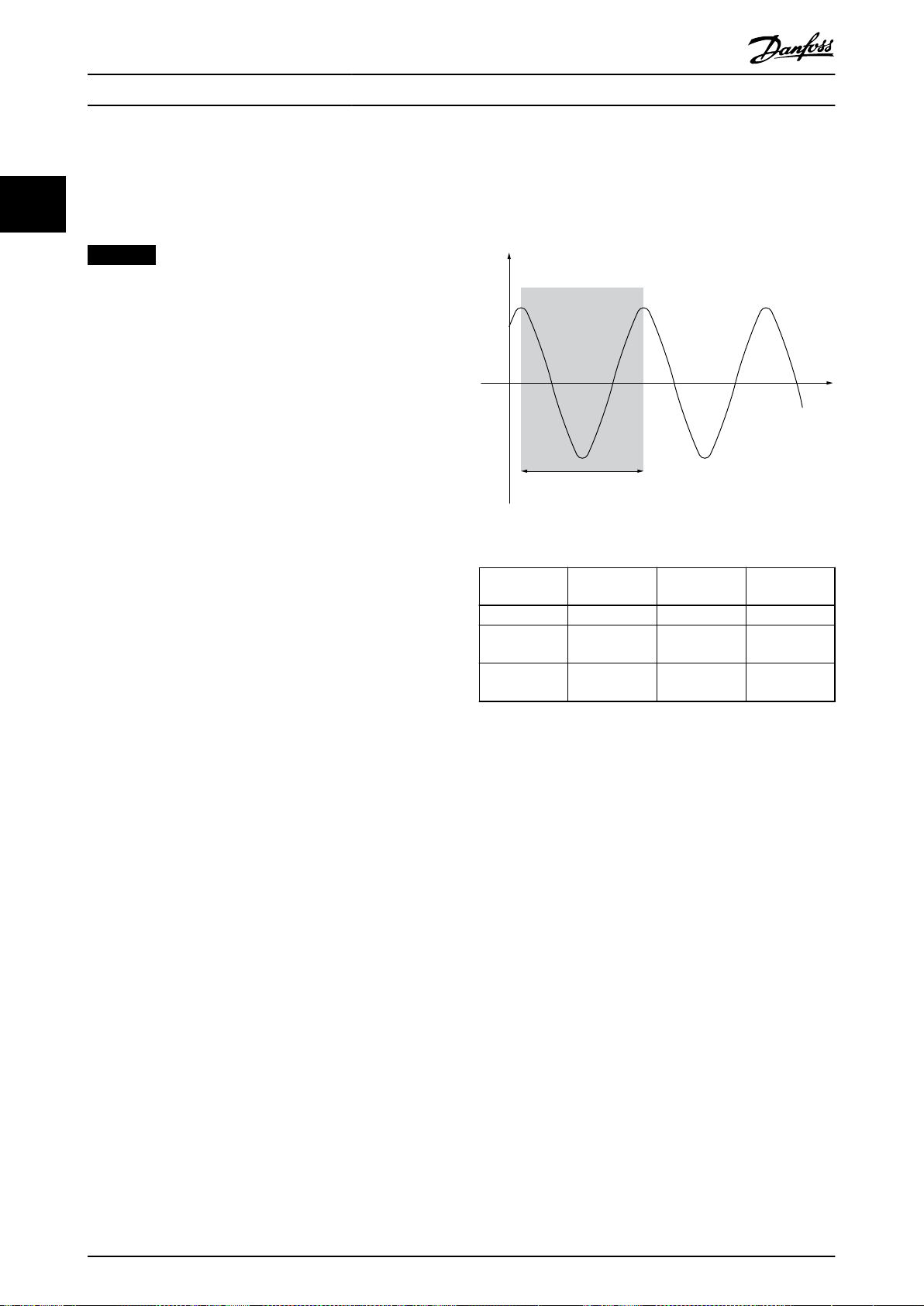
130BA183.10
y(t)
t
P
u
Product Overview
VLT® Midi Drive FC 280
2.5.6 Ziegler Nichols Tuning Method
4. Use Table 2.12 to calculate the necessary PID
control parameters.
22
Danfoss recommends the Ziegler Nichols tuning method.
To tune the PID controls of the frequency converter,
The process operator can do the nal tuning of the control
iteratively to yield satisfactory control.
NOTICE
Do not use the Ziegler Nichols Tuning method in
applications that could be damaged by the oscillations
created by marginally stable control settings.
The criteria for adjusting the parameters are based on
evaluating the system at the limit of stability rather than
on taking a step response. Increase the proportional gain
until observing continuous oscillations (as measured on
the feedback), that is, until the system becomes marginally
stable. The corresponding gain (Ku) is called the ultimate
gain and is the gain, at which the oscillation is obtained.
The period of the oscillation (Pu) (called the ultimate
period) is determined as shown in Illustration 2.26 and
should be measured when the amplitude of oscillation is
small.
1. Select only proportional control, meaning that
the integral time is set to the maximum value,
while the dierentiation time is set to 0.
2. Increase the value of the proportional gain until
the point of instability is reached (sustained
oscillations) and the critical value of gain, Ku, is
reached.
3. Measure the period of oscillation to obtain the
critical time constant, Pu.
Illustration 2.26 Marginally Stable System
Type of
control
PI-control 0.45 x K
PID tight
control
PID some
overshoot
Table 2.12 Ziegler Nichols Tuning for Regulator
Proportional
gain
u
0.6 x K
u
0.33 x K
u
Integral time Dierentiation
0.833 x P
0.5 x P
0.5 x P
u
u
u
time
0.125 x P
0.33 x P
–
u
u
EMC Emission and Immunity
2.6
2.6.1 General Aspects of EMC Emission
Burst transient is conducted at frequencies in the range 150 kHz to 30 MHz. Airborne interference from the frequency
converter system in the range 30 MHz to 1 GHz is generated from the frequency converter, motor cable, and motor.
Capacitive currents in the motor cable coupled with a high dU/dt from the motor voltage generate leakage currents.
Using a shielded motor cable increases the leakage current (see Illustration 2.27) because shielded cables have higher
capacitance to ground than unshielded cables. If the leakage current is not
mains in the radio frequency range below approximately 5 MHz. Since the leakage current (I1) is carried back to the unit
through the shield (I3), there is only a small electro-magnetic eld (I4) from the shielded motor cable.
The shield reduces the radiated interference but increases the low-frequency interference on the mains. Connect the motor
cable shield to the frequency converter enclosure and the motor enclosure. This is best done by using integrated shield
clamps to avoid twisted shield ends (pigtails). The shield clamps increase the shield impedance at higher frequencies, which
reduces the shield
eect and increases the leakage current (I4).
Mount the shield on the enclosure at both ends if a shielded cable is used for the following purposes:
•
•
•
Fieldbus
Network
Relay
ltered, it causes greater interference on the
36 Danfoss A/S © 05/2017 All rights reserved. MG07B302

1
2
z
z
z
L1
L2
L3
PE
U
V
W
C
S
I
2
I
1
I
3
I
4
C
S
C
S
C
S
C
S
I
4
C
S
z
PE
3
4
5
6
175ZA062.12
Product Overview Design Guide
Control cable
•
Signal interface
•
Brake
•
In some situations, however, it is necessary to break the shield to avoid current loops.
2 2
1 Ground cable
2 Shield
3 AC mains supply
4 Frequency converter
5 Shielded motor cable
6 Motor
Illustration 2.27 EMC Emission
If placing the shield on a mounting plate for the frequency converter, use a metal mounting plate to convey the shield
currents back to the unit. Ensure good electrical contact from the mounting plate through the mounting screws to the
frequency converter chassis.
When using unshielded cables, some emission requirements are not complied with, although the immunity requirements are
observed.
To reduce the interference level from the entire system (unit and installation), make motor and brake cables as short as
possible. Avoid placing cables with a sensitive signal level alongside mains, motor, and brake cables. Radio interference
higher than 50 MHz (airborne) is especially generated by the control electronics.
MG07B302 Danfoss A/S © 05/2017 All rights reserved. 37

Product Overview
2.6.2 EMC Emission
VLT® Midi Drive FC 280
22
motor, and shielded motor cables.
Filter type
(internal)
3x380–480 V 3x200–240 V 1x200–240 V Conducted Radiated Conducted Radiated Conducted Radiated
A2 lter
A1 lter
A2 lter
EMC
screw
removed
2)
A1 lter
EMC
screw
removed
2)
Supply voltage/rated power Class A2/EN 55011 Class A1/EN 55011 Class B/EN 55011
0.37–22 kW
(0.5–30 hp)
–
– –
0.37–7.5 kW
(0.5–10 hp)
11–22 kW
(15–30 hp)
– –
0.37–22 kW
(0.5–30 hp)
–
– –
0.37–7.5 kW
(0.5–10 hp)
11–22 kW
(15–30 hp)
– –
– – 25 m (82 ft)
0.37–4 kW
(0.5–5.4 hp)
– 25 m (82 ft)
0.37–2.2 kW
(0.5–3 hp)
– – – – – –
– – 25 m (82 ft)
– – 50 m (164 ft)
0.37–2.2 kW
(0.5–3 hp)
40 m (131 ft)
– – – – – – – –
0.37–4 kW
(0.5–5.4 hp)
– – – – – – –
0.37–2.2 kW
(0.5–3 hp)
– – – – – –
– – 5 m (16.4 ft)
– – 5 m (16.4 ft)
0.37–2.2 kW
(0.5–3 hp)
5 m (16.4 ft)
Yes
Yes
Yes
Yes
Yes
Yes
Yes
Yes
1)
1)
1)
1)
1)
1)
1)
1)
– – – –
– – – –
25 m
(82 ft)
50 m
(164 ft)
40 m
(131 ft)
Yes – –
Yes – –
Yes
15 m
(49.2 ft)
– – – –
– – – –
– – – –
–
The test results in Table 2.13 have been obtained using a system with a frequency converter (with the mounting plate), a
Table 2.13 EMC Emission (Filter type: internal)
1) Frequency range from 150 kHz to 30 MHz is not harmonized between IEC/EN 61800-3 and EN 55011 and not mandatorily included.
2) Low ground leakage current. Compatible to run on ELCB/IT mains.
The test results in Table 2.14 have been obtained using a system with a frequency converter (with the mounting plate), an
external
lter, a motor, and shielded motor cables. 3-phase 380–480 V frequency converter should be with internal A1 lter.
38 Danfoss A/S © 05/2017 All rights reserved. MG07B302

Product Overview Design Guide
Filter type
(external)
Supply voltage/rated power Class A2/EN 55011 Class A1/EN 55011 Class B/EN 55011
3x380–480 V 3x200–240 V 1x200–240 V Conducted Radiated Conducted Radiated Conducted Radiated
EMC lter
dU/dt
lter
Sine-wave
lter
EMC lter
+
sine-wave
lter
0.37–22 kW
(0.5–30 hp)
–
– –
0.37–7.5 kW
(0.5–10 hp)
11–22 kW
(15–30 hp)
–
– –
0.37–7.5 kW
(0.5–10 hp)
11–15 kW
(15–20 hp)
18.5–22 kW
(25–30 hp)
–
– –
0.37–15 kW
(0.5–20 hp)
18.5–22 kW
(25–30 hp)
–
– –
– – 100 m (328 ft)
0.37–4 kW
(0.5–5.4 hp)
– – – – – – –
0.37–2.2 kW
(0.5–3 hp)
100 m (328 ft)
Yes
Yes
– – – – – – – –
– – 150 m (492 ft)
0.37–4 kW
(0.5–5.4 hp)
– – – – – – –
0.37–2.2 kW
(0.5–3 hp)
– – 50 m (164 ft)
– – 150 m (492 ft)
– – 150 m (492 ft)
0.37–4 kW
(0.5–5.4 hp)
– – – – – – –
0.37–2.2 kW
(0.5–3 hp)
50 m (164 ft)
– – 150 m (492 ft)
– – – – – –
Yes
Yes
Yes
Yes
Yes
Yes
– – – – – – – –
0.37–4 kW
(0.5–5.4 hp)
– – – – – – –
0.37–2.2 kW
(0.5–3 hp)
150 m (492 ft)
Yes
100 m
1)
(328 ft)
100 m
1)
(328 ft)
1)
40 m
(131 ft)
1)
50 m
(164 ft)
1)
50 m
(164 ft)
100 m
1)
(328 ft)
1)
50 m
(164 ft)
100 m
1)
(328 ft)
100 m
1)
(328 ft)
Yes
Yes
Yes – –
Yes – –
Yes – –
Yes – –
Yes – –
Yes – –
Yes – –
25 m
(82 ft)
40 m
(131 ft)
–
2 2
–
Table 2.14 EMC Emission (Filter type: external)
1) Frequency range from 150 kHz to 30 MHz is not harmonized between IEC/EN 61800-3 and EN 55011 and not mandatorily included.
MG07B302 Danfoss A/S © 05/2017 All rights reserved. 39

Product Overview
2.6.3 EMC Immunity
VLT® Midi Drive FC 280
22
VLT® Midi Drive FC 280 complies with the industrial environment requirements, which are higher than the requirements for
the home and oce environments. Therefore, FC 280 also complies with the lower requirements for home and oce
environments with a large safety margin.
To document immunity against burst transient from electrical phenomena, the following immunity tests have been made on
a system consisting of:
A frequency converter (with options if relevant).
•
A shielded control cable.
•
A control box with potentiometer, motor cable, and motor.
•
The tests were performed in accordance with the following basic standards:
EN 61000-4-2 (IEC 61000-4-2) Electrostatic discharges (ESD): Simulation of electrostatic discharges from human
•
beings.
EN 61000-4-3 (IEC 61000-4-3) Radiated immunity: Amplitude modulated simulation of the
•
eects of radar and
radio communication equipment and mobile communications equipment.
EN 61000-4-4 (IEC 61000-4-4) Burst transients: Simulation of interference caused by switching a contactor, relay,
•
or similar devices.
EN 61000-4-5 (IEC 61000-4-5) Surge transients: Simulation of transients caused by, for example, lightning that
•
strikes near installations.
EN 61000-4-6 (IEC 61000-4-6) Conducted immunity: Simulation of the eect from radio-transmission equipment
•
joined by connection cables.
FC 280 follows IEC 61800-3 standard. See Table 2.15 for details.
Voltage range: 380–480 V
Product standard 61800-3
Test
Acceptance criterion B B B A A
Mains cable – – 2 kV CN
Motor cable – – 4 kV CCC – 10 V
Brake cable – – 4 kV CCC – 10 V
Load sharing cable – – 4 kV CCC – 10 V
Relay cable – – 4 kV CCC – 10 V
Control cable – –
Standard/eldbus cable – –
LCP cable – –
Enclosure
Denitions
CD: Contact discharge
AD: Air discharge
ESD Radiated
immunity
4 kV CD
8 kV AD
10 V/m – – –
DM: Dierential mode
CM: Common mode
Burst Surge Conducted
2 kV/2 Ω DM
2 kV/12 Ω CM
Length >2 m (6.6 ft)
1 kV CCC
Length >2 m (6.6 ft)
1 kV CCC
Length >2 m (6.6 ft)
1 kV CCC
CN: Direct injection through coupling network
CCC: Injection through capacitive coupling clamp
Unshielded:
1 kV/42 Ω CM
Unshielded:
1 kV/42 Ω CM
– 10 V
immunity
10 V
10 V
10 V
RMS
RMS
RMS
RMS
RMS
RMS
RMS
RMS
Table 2.15 EMC Immunity
40 Danfoss A/S © 05/2017 All rights reserved. MG07B302

130BD447.11
12
4
3
ab
M
130BB955.12
a
b
Leakage current
Motor cable length
Product Overview Design Guide
2.7 Galvanic Isolation
PELV oers protection through extra low voltage.
Protection against electric shock is ensured when the
electrical supply is of the PELV type and the installation is
made as described in local/national regulations on PELV
supplies.
All control terminals and relay terminals 01–03 comply
with PELV (protective extra low voltage). This does not
apply to grounded Delta leg above 400 V.
Galvanic (ensured) isolation is obtained by fullling
requirements for higher isolation and by providing the
relevant creapage/clearance distances. These requirements
are described in the EN 61800-5-1 standard.
The components that make up the electrical isolation, as
shown in Illustration 2.28, also comply with the
requirements for higher isolation and the relevant test as
described in EN 61800-5-1.
The PELV galvanic isolation can be shown in 3 locations
(see Illustration 2.28):
WARNING
Before touching any electrical parts, ensure that other
voltage inputs have been disconnected, such as load
sharing (linkage of DC intermediate circuit) and the
motor connection for kinetic back-up. Observe the
discharge time stated in chapter Safety in the VLT® Midi
Drive FC 280 Operating Guide. Failure to follow
recommendations could result in death or serious injury.
2.8 Ground Leakage Current
Follow national and local codes regarding protective
grounding of equipment with a leakage current >3.5 mA.
Frequency converter technology implies high frequency
switching at high power. This switching generates a
leakage current in the ground connection. A fault current
in the frequency converter at the output power terminals
might contain a DC component, which can charge the
lter capacitors and cause a transient ground current.
The ground leakage current is made up of several contributions and depends on various system congurations
including RFI ltering, shielded motor cables, and
frequency converter power.
2 2
To maintain PELV, all connections made to the control
terminals must be PELV, for example, the thermistor must
be reinforced/double insulated.
1 Power supply (SMPS) for control cassette
2 Communication between power card and control cassette
3 Isolation between STO inputs and IGBT circuit
4 Customer relay
Illustration 2.28 Galvanic Isolation
The functional galvanic isolation (a and b on
Illustration 2.28) is for the 24 V back-up option and the
RS485 standard bus interface.
Illustration 2.29 Inuence the Cable Length and Power Size on
Leakage Current, Pa>P
b
The leakage current also depends on the line distortion.
MG07B302 Danfoss A/S © 05/2017 All rights reserved. 41

130BB956.12
THDv=0%
THDv=5%
Leakage current
130BB958.12
f
sw
Cable
150 Hz
3rd harmonics
50 Hz
Mains
RCD with low f
cut-
RCD with high f
cut-
Leakage current
Frequency
130BB957.11
Leakage current [mA]
100 Hz
2 kHz
100 kHz
Product Overview
VLT® Midi Drive FC 280
22
Illustration 2.31 Mains Contributions to Leakage Current
Illustration 2.30 Inuence of Line Distortion on Leakage
Current
NOTICE
High leakage current may cause the RCDs to switch o.
To avoid this problem, remove the RFI screw when a
lter is being charged.
EN/IEC61800-5-1 (Power Drive System Product Standard)
requires special care if the leakage current exceeds 3.5 mA.
Grounding must be reinforced in 1 of the following ways:
Ground wire (terminal 95) of at least 10 mm
•
(8 AWG).
2 separate ground wires that comply with the
•
dimensioning rules.
See EN/IEC61800-5-1 for further information.
Using RCDs
Where residual current devices (RCDs), also known as earth
leakage circuit breakers (ELCBs), are used, comply with the
following:
Use RCDs of type B only, which are capable of
•
detecting AC and DC currents.
Use RCDs with an inrush delay to prevent faults
•
caused by transient ground currents.
Dimension RCDs according to the system congu-
•
ration and environmental considerations.
2
Illustration 2.32 Inuence of Cut-o Frequency of the RCD on
what is Responded to/Measured
For more details, refer to the RCD Application Note.
Brake Functions
2.9
2.9.1 Mechanical Holding Brake
A mechanical holding brake mounted directly on the
motor shaft normally performs static braking.
NOTICE
When the holding brake is included in a safety chain, a
frequency converter cannot provide a safe control of a
mechanical brake. Include a redundancy circuitry for the
brake control in the total installation.
42 Danfoss A/S © 05/2017 All rights reserved. MG07B302

T
ta
tc
tb
to ta
tc
tb
to ta
130BA167.10
Load
Time
Speed
Product Overview Design Guide
2.9.2 Dynamic Braking
Dynamic braking is established by:
Resistor brake: A brake IGBT keeps the
•
overvoltage under a certain threshold by
directing the brake energy from the motor to the
connected brake resistor (parameter 2-10 Brake
Function = [1] Resistor brake).
Adjust the threshold in parameter 2-14 Brake
voltage reduce, with 70 V range for 3x380–480 V.
AC brake: The brake energy is distributed in the
•
motor by changing the loss conditions in the
motor. The AC brake function cannot be used in
applications with high cycling frequency as this
overheats the motor (parameter 2-10 Brake
Function = [2] AC brake).
DC brake: An overmodulated DC current added to
•
the AC current works as an eddy current brake
(parameter 2-02 DC Braking Time≠0 s).
2.9.3 Brake Resistor Selection
To handle higher demands by generatoric braking, a brake
resistor is necessary. Using a brake resistor ensures that the
heat is absorbed in the brake resistor and not in the
frequency converter. For more information, see the VLT
Brake Resistor MCE 101 Design Guide.
If the amount of kinetic energy transferred to the resistor
in each braking period is not known, calculate the average
power based on the cycle time and braking time. The
resistor intermittent duty cycle is an indication of the duty
cycle at which the resistor is active. Illustration 2.33 shows a
typical braking cycle.
The intermittent duty cycle for the resistor is calculated as
follows:
®
Illustration 2.33 Typical Braking Cycle
Power range:
0.37–22 kW (0.5–30 hp) 3x380–480 V
0.37–3.7 kW (0.5–5 hp) 3x200–240 V
Cycle time (s) 120
Braking duty cycle at 100% torque Continuous
Braking duty cycle at overtorque
(150/160%)
Table 2.16 Braking at High Overload Torque Level
40%
Danfoss oers brake resistors with duty cycles of 10% and
40%. If a 10% duty cycle is applied, the brake resistors are
able to absorb brake power for 10% of the cycle time. The
remaining 90% of the cycle time is used for dissipating
excess heat.
NOTICE
Make sure that the resistor is designed to handle the
required braking time.
The maximum allowed load on the brake resistor is stated
as a peak power at a given intermittent duty cycle and can
be calculated as:
2 2
Duty cycle = tb/T
tb is the braking time in seconds.
T = cycle time in seconds.
Brake resistance calculation
2
U
x0 . 83
Ω =
dc,br
P
peak
R
br
where
P
peak
= P
x Mbr [%] x η
motor
motor
x η
VLT
[W]
As shown, the brake resistance depends on the DC-link
voltage (Udc).
Size Brake active
U
dc,br
FC 280
3x380–480 V
MG07B302 Danfoss A/S © 05/2017 All rights reserved. 43
FC 280
3x200–240 V
Table 2.17 Threshold of the Brake Resistance
770 V 800 V 800 V
390 V 410 V 410 V
Warning
before cutout
Cutout (trip)

Product Overview
VLT® Midi Drive FC 280
The threshold can be adjusted in parameter 2-14 Brake
2.9.4 Control with Brake Function
voltage reduce, with 70 V range.
The brake is protected against short-circuiting of the brake
22
NOTICE
The greater the reduction value, the faster the reaction
to a generator overload. Should only be used if there are
problems with overvoltage in the DC-link voltage.
resistor, and the brake transistor is monitored to ensure
that short-circuiting of the transistor is detected. A relay/
digital output can be used for protecting the brake resistor
from overloading caused by a fault in the frequency
converter.
In addition, the brake enables readout of the momentary
NOTICE
Make sure that the brake resistor can cope with a
voltage of 410 V or 800 V.
power and the mean power for the latest 120 s. The brake
can also monitor the power energizing and make sure that
it does not exceed a limit selected in parameter 2-12 Brake
Power Limit (kW).
Danfoss recommends calculating the brake resistance R
according to the following formula. The recommended
brake resistance guarantees that the frequency converter is
able to brake at the highest braking torque (M
br(%)
160%.
2
U
x100x0.83
R
Ω =
rec
η
is typically at 0.80 (≤7.5 kW (10 hp)); 0.85 (11–22 kW
motor
dc
P
motor
xM
br( % )
xη
VLT
xη
motor
(15–30 hp))
η
is typically at 0.97
VLT
) of
rec
NOTICE
Monitoring the brake power is not a safety function. A
thermal switch is required to prevent the brake power
from exceeding the limit. The brake resistor circuit is not
ground leakage protected.
Overvoltage control (OVC) (exclusive brake resistor) can be
selected as an alternative brake function in
parameter 2-17 Over-voltage Control. This function is active
for all units. The function ensures that a trip can be
avoided if the DC-link voltage increases. This is done by
For FC 280, R
at 160% braking torque is written as:
rec
increasing the output frequency to limit the voltage from
the DC link. It is a useful function, for example if the ramp-
480
480
V: R
V: R
rec
rec
396349
=
397903
=
P
P
motor
motor
Ω
Ω
1)
2)
1) For frequency converters ≤7.5 kW (10 hp) shaft output.
2) For frequency converters 11–22 kW (15–30 hp) shaft
output.
down time is too short to avoid tripping of the frequency
converter. In this situation, the ramp-down time is
extended.
NOTICE
OVC can be activated when running a PM motor (when
parameter 1-10 Motor Construction is set to [1] PM non-
salient SPM).
NOTICE
The resistance of the brake resistor should not be higher
than the value recommended by Danfoss. For brake
resistors with a higher ohmic value, the 160% braking
torque may not be achieved because the frequency
converter might cut out for safety reasons.
The resistance should be bigger than R
min
.
NOTICE
If a short circuit in the brake transistor occurs, prevent
power dissipation in the brake resistor by using a mains
switch or contactor to disconnect the mains for the
frequency converter. The frequency converter can control
the contactor.
NOTICE
Do not touch the brake resistor because it can get hot
during braking. To avoid re risk, place the brake resistor
in a secure environment.
2.10 Motor Insulation
Modern design of motors for use with frequency
converters have a high degree of insulation to account for
new generation high-eciency IGBTs with high dU/dt. For
retrot in old motors it is necessary to conrm the motor
insulation or to mitigate with a dU/dt lter or if necessary
a sine-wave lter.
2.10.1 Sine-wave Filters
When a frequency converter controls a motor, resonance
noise is heard from the motor. This noise, which is the
result of the motor design, occurs every time an inverter
switch in the frequency converter is activated. The
frequency of the resonance noise thus corresponds to the
switching frequency of the frequency converter.
44 Danfoss A/S © 05/2017 All rights reserved. MG07B302

. . .
. . .
Par. 13-11
Comparator Operator
Par. 13-43
Logic Rule Operator 2
Par. 13-51
SL Controller Event
Par. 13-52
SL Controller Action
130BB671.13
Coast
Start timer
Set Do X low
Select set-up 2
. . .
Running
Warning
Torque limit
Digital input X 30/2
. . .
=
TRUE longer than..
. . .
. . .
130BA062.14
State 1
13-51.0
13-52.0
State 2
13-51.1
13-52.1
Start
event P13-01
State 3
13-51.2
13-52.2
State 4
13-51.3
13-52.3
Stop
event P13-02
Stop
event P13-02
Stop
event P13-02
Product Overview Design Guide
Danfoss supplies a sine-wave lter to dampen the acoustic
motor noise.
The lter reduces the ramp-up time of the voltage, the
peak load voltage U
, and the ripple current ΔI to the
PEAK
motor, which means that current and voltage become
almost sinusoidal. So, the acoustic motor noise is reduced
to a minimum.
The ripple current in the sine-wave lter coils also causes
some noise. Solve the problem by integrating the lter in a
cabinet or similar.
2.10.2 dU/dt Filters
Danfoss supplies dU/dt lters. dU/dt lters are dierential
mode, low-pass lters that reduce motor terminal phaseto-phase peak voltages and reduce the rise time to a level
that lowers the stress on the insulation at the motor
windings. This is especially an issue with short motor
cables.
Compared to the sine-wave lters (see chapter 2.10.1 Sine-
wave Filters), the dU/dt lters have a cut-o frequency
above the switching frequency.
Smart Logic Controller
2.11
Smart logic control (SLC) is a sequence of user-dened
actions (see parameter 13-52 SL Controller Action [x])
executed by the SLC when the associated user-dened
event (see parameter 13-51 SL Controller Event [x]) is
evaluated as true by the SLC.
The condition for an event can be a particular status or
that the output from a logic rule or a comparator operand
becomes true. That leads to an associated action as shown
in Illustration 2.34.
2 2
Illustration 2.34 Associated Action
Events and actions are each numbered and linked in pairs
(states). This means that when event [0] is fullled (attains
the value true), action [0] is executed. After this, the
conditions of event [1] are evaluated and if evaluated true,
action [1] is executed, and so on. Only 1 event is evaluated
at any time. If an event is evaluated as false, nothing
happens (in the SLC) during the current scan interval, and
no other events are evaluated. When the SLC starts, it
evaluates event [0] (and only event [0]) each scan interval.
Only when event [0] is evaluated true, the SLC executes
action [0] and starts evaluating event [1]. It is possible to
program 1–20 events and actions.
When the last event/action has been executed, the
sequence starts over again from event [0]/action [0].
Illustration 2.35 shows an example with 3 event/actions:
MG07B302 Danfoss A/S © 05/2017 All rights reserved. 45
Illustration 2.35 Sequence with 3 Events/Actions

Par. 13-11
Comparator Operator
=
TRUE longer than.
. . .
. . .
Par. 13-10
Comparator Operand
Par. 13-12
Comparator Value
130BB672.10
. . .
. . .
. . .
. . .
Par. 13-43
Logic Rule Operator 2
Par. 13-41
Logic Rule Operator 1
Par. 13-40
Logic Rule Boolean 1
Par. 13-42
Logic Rule Boolean 2
Par. 13-44
Logic Rule Boolean 3
130BB673.10
Product Overview
VLT® Midi Drive FC 280
22
Comparators
Comparators are used for comparing continuous variables
(for example output frequency, output current, and analog
input) to xed preset values.
The control unit may attempt to correct the ramp if
possible (parameter 2-17 Over-voltage Control).
Incorrect slip compensation setting may cause
•
higher DC-link voltage.
The frequency converter turns o to protect the transistors
and the DC link capacitors when a certain voltage level is
reached.
To select the method used for controlling the DC-link
voltage level, see parameter 2-10 Brake Function and
parameter 2-17 Over-voltage Control.
Mains drop-out
Illustration 2.36 Comparators
During a mains drop-out, the frequency converter keeps
running until the DC-link voltage drops below the
minimum stop level, which is:
Logic rules
Combine up to 3 boolean inputs (true/false inputs) from
timers, comparators, digital inputs, status bits, and events
using the logical operators and, or, and not.
314 V for 3x380–480 V.
•
202 V for 3x200–240 V.
•
225 V for 1x200–240 V.
•
The mains voltage before the drop-out and the motor load
determines how long it takes for the inverter to coast.
Static overload in VVC+ mode
When the frequency converter is overloaded, the torque
limit in parameter 4-16 Torque Limit Motor Mode/
parameter 4-17 Torque Limit Generator Mode is reached, the
control unit reduces the output frequency to reduce the
Illustration 2.37 Logic Rules
load.
If the overload is excessive, a overcurrent which makes the
frequency converter cut out after approximately 5–10 s
may occur.
2.12 Extreme Running Conditions
Short circuit (motor phase-to-phase)
Operation within the torque limit is limited in time (0–60 s)
in parameter 14-25 Trip Delay at Torque Limit.
The frequency converter is protected against short circuits
by current measurement in each of the 3 motor phases or
2.12.1 Motor Thermal Protection
in the DC link. A short circuit between 2 output phases
causes an overcurrent in the frequency converter. The
frequency converter is turned o individually when the
To protect the application from serious damage, VLT® Midi
Drive FC 280 oers several dedicated features.
short-circuit current exceeds the allowed value (alarm 16,
trip lock).
Switching on the output
Switching on the output between the motor and the
frequency converter is fully allowed, and does not damage
the frequency converter. However, fault messages may
appear.
Motor-generated overvoltage
The voltage in the DC link is increased when the motor
acts as a generator. This occurs in following cases:
The load drives the motor (at constant output
•
frequency from the frequency converter).
If the inertia moment is high during deceleration
•
(ramp-down), the friction is low and the rampdown time is too short for the energy to be
dissipated as a loss in the frequency converter,
46 Danfoss A/S © 05/2017 All rights reserved. MG07B302
the motor, and the installation.
Torque limit
The torque limit protects the motor from being overloaded
independent of the speed. Torque limit is controlled in
parameter 4-16 Torque Limit Motor Mode and
parameter 4-17 Torque Limit Generator Mode.
Parameter 14-25 Trip Delay at Torque Limit controls the time
before the torque limit warning trips.
Current limit
Parameter 4-18 Current Limit controls the current limit, and
parameter 14-24 Trip Delay at Current Limit controls the
time before the current limit warning trips.
Minimum speed limit
Parameter 4-12 Motor Speed Low Limit [Hz] sets the
minimum output speed that the frequency converter can
provide.

1.21.0 1.4
30
10
20
100
60
40
50
1.81.6 2.0
2000
500
200
400
300
1000
600
t [s]
175ZA052.12
f
OUT
= 2 x f
M,N
f
OUT
= 0.2 x f
M,N
f
OUT
= 1 x f
M,N
(par. 1-23)
IMN(par. 1-24)
I
M
Product Overview Design Guide
Maximum speed limit
Parameter 4-14 Motor Speed High Limit [Hz] or
parameter 4-19 Max Output Frequency sets the maximum
output speed that the frequency converter can provide.
ETR (electronic thermal relay)
The frequency converter ETR function measures the actual
current, speed, and time to calculate motor temperature.
The function also protects the motor from being
overheated (warning or trip). An external thermistor input
is also available. ETR is an electronic feature that simulates
a bimetal relay based on internal measurements. The
characteristic is shown in Illustration 2.38.
2 2
Illustration 2.38 ETR
The X-axis shows the ratio between I
motor
and I
motor
nominal. The Y-axis shows the time in seconds before the
ETR cuts o and trips the frequency converter. The curves
show the characteristic nominal speed at twice the
nominal speed and at 0.2 x the nominal speed.
At lower speed, the ETR cuts o at lower heat due to less
cooling of the motor. In that way, the motor is protected
from being overheated even at low speed. The ETR feature
calculates the motor temperature based on actual current
and speed. The calculated temperature is visible as a
readout parameter in parameter 16-18 Motor Thermal.
MG07B302 Danfoss A/S © 05/2017 All rights reserved. 47
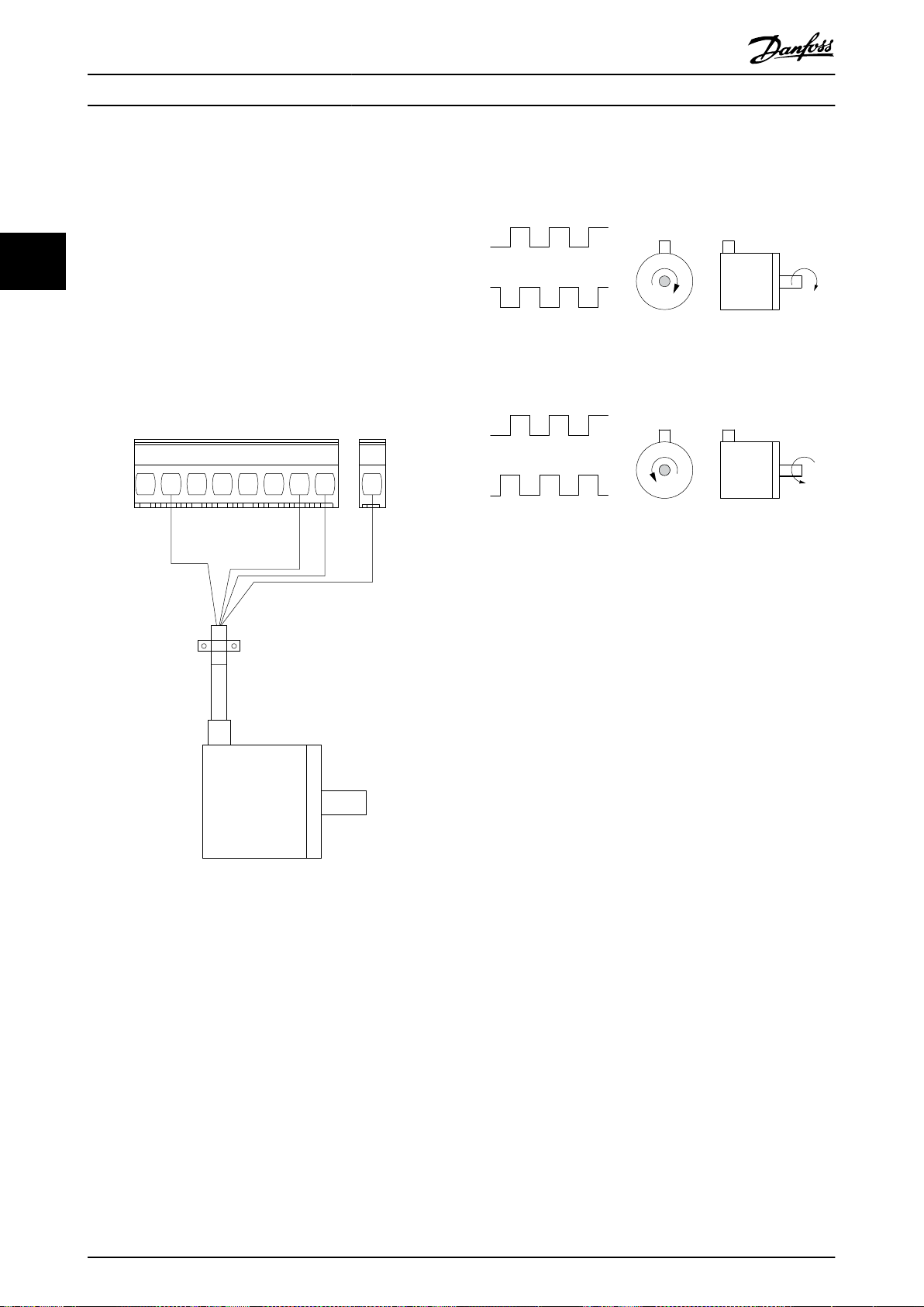
130BE805.11
+24 V DC
+24 V DC
A
B
GND
12 13 18 19 3227 29 33 55
B
A
B
A
130BA646.10
CW
CCW
Application Examples
3 Application Examples
3.1 Introduction
VLT® Midi Drive FC 280
33
3.1.1 Encoder Connection
The purpose of this guideline is to ease the set-up of
encoder connection to the frequency converter. Before
setting up the encoder, the basic settings for a closed-loop
speed control system are shown.
Illustration 3.2 24 V Incremental Encoder, Maximum Cable
Length 5 m (16.4 ft)
3.1.2 Encoder Direction
The order in which the pulses enter the frequency
converter determines the direction of the encoder.
Clockwise direction means that channel A is 90 electrical
degrees before channel B.
Counterclockwise direction means that channel B is 90
electrical degrees before A.
The direction is determined by looking into the shaft end.
3.1.3 Closed-loop Drive System
A drive system usually consists of more elements such as:
Motor.
•
Brake (gearbox, mechanical brake).
Illustration 3.1 24 V Encoder
•
Frequency converter.
•
Encoder as feedback system.
•
Brake resistor for dynamic brake.
•
Transmission.
•
Load.
•
Applications demanding mechanical brake control usually
need a brake resistor.
48 Danfoss A/S © 05/2017 All rights reserved. MG07B302

130BE728.10
Motor
Gearbox
Load
Transmission
Encoder Mech. brake
Brake resistor
130BF096.10
FC
+24 V
D IN
D IN
D IN
D IN
D IN
+10 V
A IN
A IN
COM
12
13
18
19
27
29
32
33
50
53
54
55
42
A OUT
D IN
+24 V
130BE204.11
+24 V
D IN
D IN
D IN
D IN
D IN
D IN
+10 V
A IN
A IN
COM
A OUT
12
13
18
19
27
29
32
33
50
53
54
55
42
0 ~10 V
+
-
FC
+24 V
130BF097.10
+24 V
D IN
D IN
D IN
D IN
D IN
D IN
+10 V
A IN
A IN
COM
A OUT
12
13
18
19
27
29
32
33
50
53
54
55
42
4 - 20mA
+
-
FC
+24 V
Application Examples Design Guide
3.2.2 Speed
Parameters
Function Setting
Parameter 6-10 T
erminal 53 Low
0.07 V*
Voltage
Parameter 6-11 T
erminal 53 High
10 V*
Voltage
Parameter 6-14 T
erminal 53 Low
0
Ref./Feedb. Value
Parameter 6-15 T
erminal 53 High
50
Ref./Feedb. Value
Parameter 6-19 T
erminal 53 mode
[1] Voltage
* = Default value
Notes/comments:
3 3
Illustration 3.3 Basic Set-up for Closed-loop Speed Control
Table 3.2 Analog Speed Reference (Voltage)
Parameters
Application Examples
3.2
Function Setting
Parameter 6-22 T
3.2.1 AMA
erminal 54 Low
4 mA*
Current
Parameters
Function Setting
Parameter 1-29 A
utomatic Motor
Adaptation
(AMA)
Parameter 5-12 T
erminal 27
Digital Input
[1] Enable
complete
AMA
*[2] Coast
inverse
* = Default value
Notes/comments: Set
parameter group 1-2* Motor
Data according to motor
specications.
NOTICE
If terminal 13 and 27 are
not connected, set
parameter 5-12 Terminal 27
Digital Input to [0] No
operation.
Table 3.3 Analog Speed Reference (Current)
Parameter 6-23 T
erminal 54 High
Current
Parameter 6-24 T
erminal 54 Low
Ref./Feedb. Value
Parameter 6-25 T
erminal 54 High
Ref./Feedb. Value
Parameter 6-29 T
erminal 54 mode
* = Default value
Notes/comments:
20 mA*
0
50
[0] Current
Table 3.1 AMA with T27 Connected
MG07B302 Danfoss A/S © 05/2017 All rights reserved. 49

130BE208.11
+24 V
D IN
D IN
D IN
D IN
D IN
D IN
+10 V
A IN
A IN
COM
A OUT
12
13
18
19
27
29
32
33
50
53
54
55
42
≈ 5kΩ
FC
+24 V
FC
+24 V
D IN
D IN
D IN
D IN
D IN
D IN
+10 V
A IN
A IN
COM
A OUT
12
13
18
19
27
29
32
33
50
53
54
55
42
130BF100.10
+24 V
130BB840.12
Speed
Reference
Start (18)
Freeze ref (27)
Speed up (29)
Speed down (32)
130BF098.10
FC
+24 V
D IN
D IN
D IN
D IN
D IN
D IN
+10 V
A IN
A IN
COM
A OUT
12
19
18
27
29
32
33
50
53
54
55
42
+24 V 13
Application Examples
VLT® Midi Drive FC 280
Parameters
Function Setting
Parameter 6-10 T
erminal 53 Low
0.07 V*
Voltage
Parameter 6-11 T
33
erminal 53 High
10 V*
Voltage
Parameter 6-14 T
erminal 53 Low
0
Illustration 3.4 Speed Up/Speed Down
Ref./Feedb. Value
Parameter 6-15 T
erminal 53 High
Ref./Feedb. Value
Parameter 6-19 T
erminal 53 mode
* = Default value
Notes/comments:
50
[1] Voltage
3.2.3 Start/Stop
Parameters
Function Setting
Parameter 5-10 Ter
minal 18 Digital
[8] Start
Input
Table 3.4 Speed Reference (Using a Manual Potentiometer)
Parameters
Function Setting
Parameter 5-10 T
erminal 18
*[8] Start
Digital Input
Parameter 5-12 T
erminal 27
[19] Freeze
Reference
Digital Input
Parameter 5-13 T
[21] Speed Up
erminal 29
Digital Input
Parameter 5-14 T
erminal 32
[22] Speed
Down
Digital Input
* = Default value
Notes/comments:
Parameter 5-11 Ter
minal 19 Digital
Input
Parameter 5-12 Ter
minal 27 Digital
Input
Parameter 5-14 Ter
minal 32 Digital
Input
Parameter 5-15 Ter
minal 33 Digital
Input
Parameter 3-10 Pre
set Reference
Preset ref. 0
Preset ref. 1
Preset ref. 2
Preset ref. 3
* = Default value
*[10]
Reversing
[0] No
operation
[16] Preset
ref bit 0
[17] Preset
ref bit 1
25%
50%
75%
100%
Notes/comments:
Table 3.5 Speed Up/Speed Down
Table 3.6 Start/Stop with Reversing and 4 Preset Speeds
50 Danfoss A/S © 05/2017 All rights reserved. MG07B302

130BF099.10
FC
+24 V
D IN
D IN
D IN
D IN
D IN
D IN
+10 V
A IN
A IN
COM
A OUT
12
13
18
19
27
29
32
33
50
53
54
55
42
+24 V
130BE210.11
+24 V
D IN
D IN
D IN
D IN
D IN
+10 V
A IN
A IN
COM
A OUT
12
13
18
19
27
29
32
33
50
53
54
55
42
FC
D IN
+24 V
FC
+24 V
D IN
D IN
D IN
D IN
D IN
D IN
+10 V
A IN
A IN
COM
A OUT
R1
12
13
18
19
27
29
32
33
50
53
54
55
42
01
02
03
130BE211.11
+24 V
Application Examples Design Guide
3.2.4 External Alarm Reset
Parameters
Parameter 5-11 T
erminal 19
Digital Input
* = Default value
Notes/comments:
Function Setting
[1] Reset
3.2.6 SLC
Parameters
Function Setting
Parameter 4-30
Motor Feedback
[1] Warning
Loss Function
Parameter 4-31
Motor Feedback
50
Speed Error
Parameter 4-32
Motor Feedback
5 s
3 3
Loss Timeout
Parameter 7-00 S
peed PID
Feedback Source
[1] 24 V
encoder
Parameter 5-70 T
erm 32/33 Pulses
1024*
Per Revolution
Parameter 13-00
SL Controller
[1] On
Mode
Table 3.7 External Alarm Reset
Parameter 13-01
Start Event
Parameter 13-02
Stop Event
Parameter 13-10
Comparator
Operand
[19] Warning
[44] Reset key
[21] Warning
no.
Parameter 13-11
3.2.5 Motor Thermistor
Comparator
Operator
*[1] ≈
Parameter 13-12
NOTICE
To meet PELV insulation requirements, use reinforced or
double insulation on the thermistors.
Comparator
Value
Parameter 13-51
SL Controller
Event
Parameters
Function Setting
Parameter 1-90
Motor Thermal
[2] Thermistor
trip
Protection
Parameter 1-93 T
hermistor Source
[1] Analog
input 53
Parameter 6-19 T
erminal 53 mode
Table 3.8 Motor Thermistor
MG07B302 Danfoss A/S © 05/2017 All rights reserved. 51
* = Default value
Notes/comments:
If only a warning is needed, set
parameter 1-90 Motor Thermal
Protection to [1] Thermistor
warning.
[1] Voltage
Table 3.9 Using SLC to Set a Relay
Parameter 13-52
SL Controller
Action
Parameter 5-40 F
unction Relay
* = Default value
Notes/comments:
If the limit in the feedback
monitor is exceeded, warning
61, feedback monitor is issued.
The SLC monitors warning 61,
feedback monitor. If warning 61,
feedback monitor becomes true,
relay 1 is triggered.
External equipment could
indicate that service is required.
If the feedback error goes
below the limit again within
5 s, the frequency converter
continues, and the warning
disappears. Relay 1 persists
[O/Reset] is pressed.
until
61
[22]
Comparator 0
[32] Set
digital out A
low
[80] SL digital
output A

Safe Torque O (STO)
VLT® Midi Drive FC 280
4 Safe Torque O (STO)
The Safe Torque O (STO) function is a component in a
safety control system. STO prevents the unit from
generating the energy that is required to rotate the motor,
thus ensuring safety in emergency situations.
44
The STO function is designed and approved suitable for
the requirements of:
IEC/EN 61508: SIL2
•
IEC/EN 61800-5-2: SIL2
•
IEC/EN 62061: SILCL of SIL2
•
EN ISO 13849-1: Category 3 PL d
•
To achieve the required level of operational safety, select
and apply the components in the safety control system
appropriately. Before using STO, carry out a thorough risk
analysis on the installation to determine whether the STO
function and safety levels are appropriate and sucient.
For more information on safe torque o (STO), see chapter
6 Safe Torque
Operating Guide.
O (STO) in the VLT® Midi Drive FC 280
52 Danfoss A/S © 05/2017 All rights reserved. MG07B302

drop cable
RS485 Installation and Set-... Design Guide
5 RS485 Installation and Set-up
5.1 Introduction
5.1.1 Overview
RS485 is a 2-wire bus interface compatible with multi-drop network topology. The nodes can be connected as a bus, or via
drop cables from a common trunk line. A total of 32 nodes can be connected to 1 network segment.
Repeaters divide network segments, see Illustration 5.1.
5 5
Illustration 5.1 RS485 Bus Interface
NOTICE
Each repeater functions as a node within the segment in
which it is installed. Each node connected within a given
network must have a unique node address across all
segments.
Terminate each segment at both ends, using either the
termination switch (S801) of the frequency converters or a
biased termination resistor network. Always use shielded
twisted pair (STP) cable for bus cabling and follow good
common installation practice.
Low-impedance ground connection of the shield at every
node is important, including at high frequencies. Thus,
connect a large surface of the shield to ground, for
example with a cable clamp or a conductive cable gland.
Sometimes, it is necessary to apply potential-equalizing
cables to maintain the same ground potential throughout
the network, particularly in installations with long cables.
To prevent impedance mismatch, use the same type of
cable throughout the entire network. When connecting a
motor to the frequency converter, always use shielded
motor cable.
Cable Shielded twisted pair (STP)
Impedance [Ω]
Cable length [m
(ft)]
Table 5.1 Cable Specications
120
Maximum 1200 (3937) (including drop lines).
Maximum 500 (1640) station-to-station.
5.1.2 Network Connection
Connect the frequency converter to the RS485 network as
follows (see also Illustration 5.2):
1. Connect signal wires to terminal 68 (P+) and
terminal 69 (N-) on the main control board of the
frequency converter.
2. Connect the cable shield to the cable clamps.
MG07B302 Danfoss A/S © 05/2017 All rights reserved. 53

61 68 69
N
P
COMM. GND
130BB795.10
RS485 Installation and Set-...
VLT® Midi Drive FC 280
NOTICE
To reduce noise between conductors, use shielded,
twisted-pair cables.
5.1.5 EMC Precautions
To achieve interference-free operation of the RS485
network, Danfoss recommends the following EMC
precautions.
NOTICE
Observe relevant national and local regulations, for
example regarding protective earth connection. To avoid
Illustration 5.2 Network Connection
55
5.1.3 Hardware Set-up
To terminate the RS485 bus, use the terminator switch on
the main control board of the frequency converter.
The factory setting for the switch is OFF.
5.1.4 Parameter Settings for Modbus
Communication
Parameter Function
Parameter 8-30 Prot
ocol
Parameter 8-31 Add
ress
Parameter 8-32 Bau
d Rate
Select the application protocol to run for
the RS485 interface.
Set the node address.
NOTICE
The address range depends on the
protocol selected in
parameter 8-30 Protocol.
Set the baud rate.
NOTICE
The default baud rate depends on the
protocol selected in
parameter 8-30 Protocol.
coupling of high-frequency noise between the cables,
keep the RS485 communication cable away from motor
and brake resistor cables. Normally, a distance of
200 mm (8 in) is sucient. Maintain the greatest possible
distance between the cables, especially where cables run
in parallel over long distances. When crossing is
unavoidable, the RS485 cable must cross motor and
brake resistor cables at an angle of 90°.
5.2 FC Protocol
5.2.1 Overview
The FC protocol, also referred to as FC bus or standard bus,
is the Danfoss standard eldbus. It denes an access
technique according to the master/slave principle for
communications via a eldbus.
One master and a maximum of 126 slaves can be
connected to the bus. The master selects the individual
slaves via an address character in the telegram. A slave
itself can never transmit without rst being requested to
do so, and direct telegram transfer between the individual
slaves is not possible. Communications occur in the halfduplex mode.
The master function cannot be transferred to another node
(single-master system).
Parameter 8-33 Pari
ty / Stop Bits
Parameter 8-35 Min
imum Response
Delay
Parameter 8-36 Ma
ximum Response
Delay
Table 5.2 Modbus Communication Parameter Settings
54 Danfoss A/S © 05/2017 All rights reserved. MG07B302
Set the parity and number of stop bits.
NOTICE
The default selection depends on the
protocol selected in
parameter 8-30 Protocol.
Specify a minimum delay time between
receiving a request and transmitting a
response. This function is for overcoming
modem turnaround delays.
Specify a maximum delay time between
transmitting a request and receiving a
response.

0 1 32 4 5 6 7
195NA036.10
Start
bit
Even Stop
Parity bit
STX LGE ADR DATA BCC
195NA099.10
RS485 Installation and Set-... Design Guide
The physical layer is RS485, thus utilizing the RS485 port
built into the frequency converter. The FC protocol
supports dierent telegram formats:
A short format of 8 bytes for process data.
•
A long format of 16 bytes that also includes a
•
parameter channel.
A format used for texts.
•
5.2.2 FC with Modbus RTU
The FC protocol provides access to the control word and
bus reference of the frequency converter.
The control word allows the Modbus master to control
several important functions of the frequency converter:
Start.
•
Stop of the frequency converter in various ways:
•
- Coast stop.
- Quick stop.
- DC brake stop.
- Normal (ramp) stop.
Reset after a fault trip.
•
Run at various preset speeds.
•
Run in reverse.
•
Change of the active set-up.
•
Control of the 2 relays built into the frequency
•
converter.
The bus reference is commonly used for speed control. It is
also possible to access the parameters, read their values,
and where possible, write values to them. Accessing the
parameters oers a range of control options, including
controlling the setpoint of the frequency converter when
its internal PI controller is used.
Network Conguration
5.3
FC Protocol Message Framing Structure
5.4
5.4.1 Content of a Character (byte)
Each character transferred begins with a start bit. Then 8
data bits are transferred, corresponding to a byte. Each
character is secured via a parity bit. This bit is set at 1
when it reaches parity. Parity is when there are an equal
number of 1s in the 8 data bits and the parity bit in total.
A stop bit completes a character, consisting of 11 bits in
all.
Illustration 5.3 Content of a Character
5.4.2 Telegram Structure
Each telegram has the following structure:
Start character (STX) = 02 hex.
•
A byte denoting the telegram length (LGE).
•
A byte denoting the frequency converter address
•
(ADR).
Several data bytes (variable, depending on the type of
telegram) follow.
A data control byte (BCC) completes the telegram.
Illustration 5.4 Telegram Structure
5.4.3 Telegram Length (LGE)
5 5
To enable the FC protocol for the frequency converter, set
the following parameters.
Parameter Setting
Parameter 8-30 Protocol FC
Parameter 8-31 Address 1–126
Parameter 8-32 Baud Rate 2400–115200
Parameter 8-33 Parity / Stop Bits
Table 5.3 Parameters to Enable the Protocol
MG07B302 Danfoss A/S © 05/2017 All rights reserved. 55
Even parity, 1 stop bit
(default)
The telegram length is the number of data bytes plus the
address byte ADR and the data control byte BCC.
4 data bytes LGE=4+1+1=6 bytes
12 data bytes LGE=12+1+1=14 bytes
Telegrams containing texts
Table 5.4 Length of Telegrams
1) The 10 represents the
(depending on the length of the text).
xed characters, while the n is variable
101)+n bytes

ADRLGESTX PCD1 PCD2 BCC
130BA269.10
PKE INDADRLGESTX PCD1 PCD2 BCC
130BA271.10
PWE
high
PWE
low
PKE IND
130BA270.10
ADRLGESTX PCD1 PCD2 BCCCh1 Ch2 Chn
15 14 13 12 11 10 9 8 7 6 5 4 3 2 1 0
130BB918.10
PKE IND
PWE
high
PWE
low
AK PNU
Parameter
commands
and replies
Parameter
number
RS485 Installation and Set-...
VLT® Midi Drive FC 280
5.4.4 Frequency Converter Address (ADR)
Address format 1–126
Bit 7 = 1 (address format 1–126 active).
•
Bit 0–6 = frequency converter address 1–126.
•
Bit 0–6 = 0 broadcast.
•
5.4.7 The PKE Field
The PKE eld contains 2 subelds:
Parameter command and response (AK)
•
Parameter number (PNU)
•
The slave returns the address byte unchanged to the
master in the response telegram.
5.4.5 Data Control Byte (BCC)
55
The checksum is calculated as an XOR-function. Before the
rst byte in the telegram is received, the calculated
checksum is 0.
5.4.6 The Data Field
The structure of data blocks depends on the type of
telegram. There are 3 telegram types, and the type applies
for both control telegrams (master⇒slave) and response
telegrams (slave⇒master).
The 3 types of telegram are:
Illustration 5.8 PKE Field
Bits 12–15 transfer parameter commands from master to
slave and return processed slave responses to the master.
Process block (PCD)
The PCD is made up of a data block of 4 bytes (2 words)
and contains:
Control word and reference value (from master to
•
slave)
Status word and present output frequency (from
•
slave to master)
Illustration 5.5 Process Block
Parameter block
The parameter block is used to transfer parameters
between master and slave. The data block is made up of
12 bytes (6 words) and also contains the process block.
Illustration 5.6 Parameter Block
Text block
The text block is used to read or write texts via the data
block.
Parameter commands master⇒slave
Bit number Parameter command
15 14 13 12
0 0 0 0 No command.
0 0 0 1 Read parameter value.
0 0 1 0 Write parameter value in RAM (word).
0 0 1 1
1 1 0 1
1 1 1 0
1 1 1 1 Read text.
Table 5.5 Parameter Commands
Bit number Response
15 14 13 12
0 0 0 0 No response.
0 0 0 1 Parameter value transferred (word).
0 0 1 0
0 1 1 1 Command cannot be performed.
1 1 1 1 Text transferred.
Table 5.6 Response
Write parameter value in RAM (double
word).
Write parameter value in RAM and
EEPROM (double word).
Write parameter value in RAM and
EEPROM (word).
Response slave⇒master
Parameter value transferred (double
word).
Illustration 5.7 Text Block
56 Danfoss A/S © 05/2017 All rights reserved. MG07B302
If the command cannot be performed, the slave sends
0111 Command cannot be performed response and issues
the following fault reports in Table 5.7.

RS485 Installation and Set-... Design Guide
Fault code FC specication
0 Illegal parameter number.
1 Parameter cannot be changed.
2 Upper or lower limit is exceeded.
3 Subindex is corrupted.
4 No array.
5 Wrong data type.
6 Not used.
7 Not used.
9 Description element is not available.
11 No parameter write access.
15 No text available.
17 Not applicable while running.
18 Other errors.
100 –
>100 –
130 No bus access for this parameter.
131 Write to factory set-up is not possible.
132 No LCP access.
252 Unknown viewer.
253 Request is not supported.
254 Unknown attribute.
255 No error.
Table 5.7 Slave Report
5.4.8 Parameter Number (PNU)
Bits 0–11 transfer parameter numbers. The function of the
relevant parameter is dened in the parameter description
in the VLT® Midi Drive FC 280 Programming Guide.
5.4.9 Index (IND)
parameter 0-01 Language, select the data value by entering
the value in the PWE block. Serial communication is only
capable of reading parameters containing data type 9 (text
string).
Parameter 15-40 FC Type to parameter 15-53 Power Card
Serial Number contain data type 9.
For example, read the unit size and mains voltage range in
parameter 15-40 FC Type. When a text string is transferred
(read), the length of the telegram is variable, and the texts
are of dierent lengths. The telegram length is dened in
the 2nd byte of the telegram (LGE). When using text
transfer, the index character indicates whether it is a read
or a write command.
To read a text via the PWE block, set the parameter
command (AK) to F hex. The index character high-byte
must be 4.
5.4.11 Data Types Supported by the
Frequency Converter
Unsigned means that there is no operational sign in the
telegram.
Data types Description
3 Integer 16
4 Integer 32
5 Unsigned 8
6 Unsigned 16
7 Unsigned 32
9 Text string
Table 5.8 Data Types
5 5
The index is used with the parameter number to read/
write access parameters with an index, for example,
parameter 15-30 Alarm Log: Error Code. The index consists
of 2 bytes: a low byte and a high byte.
Only the low byte is used as an index.
5.4.10 Parameter Value (PWE)
5.4.12 Conversion
The programming guide contains the descriptions of
attributes of each parameter. Parameter values are
transferred as whole numbers only. Conversion factors are
used to transfer decimals.
Parameter 4-12 Motor Speed Low Limit [Hz] has a conversion
factor of 0.1. To preset the minimum frequency to 10 Hz,
The parameter value block consists of 2 words (4 bytes),
and the value depends on the dened command (AK). The
master prompts for a parameter value when the PWE block
transfer the value 100. A conversion factor of 0.1 means
that the value transferred is multiplied by 0.1. The value
100 is thus perceived as 10.0.
contains no value. To change a parameter value (write),
write the new value in the PWE block and send from the
master to the slave.
When a slave responds to a parameter request (read
command), the present parameter value in the PWE block
is transferred and returned to the master. If a parameter
contains several data options, for example
MG07B302 Danfoss A/S © 05/2017 All rights reserved. 57

E19E H
PKE IND PWE
high
PWE
low
0000 H 0000 H 03E8 H
130BA092.10
119E H
PKE
IND
PWE
high
PWE
low
0000 H 0000 H 03E8 H
130BA093.10
1155 H
PKE IND PWE
high
PWE
low
0000 H 0000 H 0000 H
130BA094.10
130BA267.10
1155 H
PKE
IND
0000 H 0000 H 03E8 H
PWE
high
PWE
low
RS485 Installation and Set-...
VLT® Midi Drive FC 280
Conversion index Conversion factor
74 3600
2 100
1 10
0 1
-1 0.1
-2 0.01
-3 0.001
-4 0.0001
-5 0.00001
Table 5.9 Conversion
NOTICE
Parameter 4-14 Motor Speed High Limit [Hz] is a single
word, and the parameter command for write in EEPROM
is E. Parameter 4-14 Motor Speed High Limit [Hz] is 19E in
hexadecimal.
The response from the slave to the master is shown in
Illustration 5.10.
55
5.4.13 Process Words (PCD)
The block of process words is divided into 2 blocks of 16
bits, which always occur in the dened sequence.
PCD 1 PCD 2
Control telegram (master⇒slave control word)
Control telegram (slave⇒master) status word
Table 5.10 Process Words (PCD)
Examples
5.5
Reference value
Present output
frequency
Illustration 5.10 Response from Master
5.5.2 Reading a Parameter Value
Read the value in parameter 3-41 Ramp 1 Ramp Up Time.
PKE = 1155 hex - Read parameter value in
parameter 3-41 Ramp 1 Ramp Up Time:
IND = 0000 hex.
•
PWE
•
PWE
•
= 0000 hex.
HIGH
= 0000 hex.
LOW
5.5.1 Writing a Parameter Value
Change parameter 4-14 Motor Speed High Limit [Hz] to 100
Hz.
Write the data in EEPROM.
PKE = E19E hex - Write single word in
parameter 4-14 Motor Speed High Limit [Hz]:
IND = 0000 hex.
•
PWEHIGH = 0000 hex.
•
PWELOW = 03E8 hex.
•
Data value 1000, corresponding to 100 Hz, see
chapter 5.4.12 Conversion.
The telegram looks like Illustration 5.9.
Illustration 5.9 Telegram
Illustration 5.11 Telegram
If the value in parameter 3-41 Ramp 1 Ramp Up Time is
10 s, the response from the slave to the master is shown in
Illustration 5.12.
Illustration 5.12 Response
3E8 hex corresponds to 1000 decimal. The conversion
index for parameter 3-41 Ramp 1 Ramp Up Time is -2, that
is, 0.01.
Parameter 3-41 Ramp 1 Ramp Up Time is of the type
Unsigned 32.
58 Danfoss A/S © 05/2017 All rights reserved. MG07B302

RS485 Installation and Set-... Design Guide
5.6 Modbus RTU
5.6.1 Prerequisite Knowledge
Danfoss assumes that the installed controller supports the
interfaces in this manual, and strictly observes all
requirements and limitations stipulated in the controller
and frequency converter.
The built-in Modbus RTU (remote terminal unit) is
designed to communicate with any controller that
supports the interfaces dened in this manual. It is
assumed that the user has full knowledge of the
capabilities and limitations of the controller.
5.6.2 Overview
Regardless of the type of physical communication
networks, this section describes the process that a
controller uses to request access to another device. This
process includes how the Modbus RTU responds to
requests from another device, and how errors are detected
and reported. It also establishes a common format for the
layout and contents of telegram elds.
During communications over a Modbus RTU network, the
protocol:
Determines how each controller learns its device
•
address.
Recognizes a telegram addressed to it.
•
Determines which actions to take.
•
Extracts any data or other information contained
•
in the telegram.
If a reply is required, the controller constructs the reply
telegram and sends it.
Controllers communicate using a master/slave technique in
which only the master can initiate transactions (called
queries). Slaves respond by supplying the requested data
to the master, or by acting as requested in the query.
The master can address individual slaves, or initiate a
broadcast telegram to all slaves. Slaves return a response
to queries that are addressed to them individually. No
responses are returned to broadcast queries from the
master.
The Modbus RTU protocol establishes the format for the
master query by providing the following information:
The device (or broadcast) address.
•
A function code dening the requested action.
•
Any data to be sent.
•
An error-checking eld.
•
The response telegram of the slave device is also
constructed using Modbus protocol. It contains elds
conrming the action taken, any data to be returned, and
an error-checking eld. If an error occurs in receipt of the
telegram, or if the slave is unable to perform the requested
action, the slave constructs and sends an error message.
Alternatively, a timeout occurs.
5.6.3 Frequency Converter with Modbus
RTU
The frequency converter communicates in Modbus RTU
format over the built-in RS485 interface. Modbus RTU
provides access to the control word and bus reference of
the frequency converter.
The control word allows the Modbus master to control
several important functions of the frequency converter:
Start.
•
Various stops:
•
- Coast stop.
- Quick stop.
- DC brake stop.
- Normal (ramp) stop.
Reset after a fault trip.
•
Run at various preset speeds.
•
Run in reverse.
•
Change the active set-up.
•
Control built-in relay of the frequency converter.
•
The bus reference is commonly used for speed control. It is
also possible to access the parameters, read their values,
and, where possible, write values to them. Accessing the
parameters
controlling the setpoint of the frequency converter when
its internal PI controller is used.
5.7
To enable Modbus RTU on the frequency converter, set the
following parameters:
Parameter 8-30 Protocol Modbus RTU
Parameter 8-31 Address 1–247
Parameter 8-32 Baud Rate 2400–115200
Parameter 8-33 Parity / Stop Bits
Table 5.11 Network Conguration
oers a range of control options, including
Network Conguration
Parameter Setting
Even parity, 1 stop bit
(default)
5 5
MG07B302 Danfoss A/S © 05/2017 All rights reserved. 59

RS485 Installation and Set-...
VLT® Midi Drive FC 280
5.8 Modbus RTU Message Framing
5.8.3 Start/Stop Field
Structure
Telegrams start with a silent period of at least 3.5 character
5.8.1 Introduction
The controllers are set up to communicate on the Modbus
network using RTU (remote terminal unit) mode, with each
byte in a telegram containing 2 4-bit hexadecimal
characters. The format for each byte is shown in Table 5.12.
Start
55
bit
Table 5.12 Format for Each Byte
Coding system 8-bit binary, hexadecimal 0–9, A–F.
Bits per byte
Error check eld Cyclic redundancy check (CRC).
Table 5.13 Byte Details
Data byte Stop/
2 hexadecimal characters contained in each
8-bit eld of the telegram.
1 start bit.
•
8 data bits, least signicant bit sent rst.
•
1 bit for even/odd parity; no bit for no
•
parity.
1 stop bit if parity is used; 2 bits if no
•
parity.
Stop
parity
5.8.2 Modbus RTU Telegram Structure
The transmitting device places a Modbus RTU telegram
into a frame with a known beginning and ending point.
This allows receiving devices to begin at the start of the
telegram, read the address portion, determine which
device is addressed (or all devices, if the telegram is
broadcast), and to recognize when the telegram is
completed. Partial telegrams are detected and errors set as
a result. Characters for transmission must be in
hexadecimal 00–FF format in each eld. The frequency
converter continuously monitors the network bus, also
during silent intervals. When the rst eld (the address
eld) is received, each frequency converter or device
decodes it to determine which device is being addressed.
Modbus RTU telegrams addressed to 0 are broadcast
telegrams. No response is permitted for broadcast
telegrams. A typical telegram frame is shown in Table 5.14.
Start Address Function Data
T1-T2-T3-
T4
Table 5.14 Typical Modbus RTU Telegram Structure
8 bits 8 bits N x 8 bits 16 bits
CRC
check
End
T1-T2-T3-
T4
intervals. The silent period is implemented as a multiple of
character intervals at the selected network baud rate
(shown as Start T1-T2-T3-T4). The rst eld to be
transmitted is the device address. Following the last
transmitted character, a similar period of at least 3.5
character intervals marks the end of the telegram. A new
telegram can begin after this period.
Transmit the entire telegram frame as a continuous stream.
If a silent period of more than 1.5 character intervals
occurs before completion of the frame, the receiving
device
ushes the incomplete telegram and assumes that
the next byte is the address eld of a new telegram.
Similarly, if a new telegram begins before 3.5 character
intervals after a previous telegram, the receiving device
considers it a continuation of the previous telegram. This
behavior causes a timeout (no response from the slave),
since the value in the nal CRC eld is not valid for the
combined telegrams.
5.8.4 Address Field
The address eld of a telegram frame contains 8 bits. Valid
slave device addresses are in the range of 0–247 decimal.
The individual slave devices are assigned addresses in the
range of 1–247. 0 is reserved for broadcast mode, which all
slaves recognize. A master addresses a slave by placing the
slave address in the address eld of the telegram. When
the slave sends its response, it places its own address in
this address eld to let the master know which slave is
responding.
5.8.5 Function Field
The function eld of a telegram frame contains 8 bits. Valid
codes are in the range of 1–FF. Function elds are used to
send telegrams between master and slave. When a
telegram is sent from a master to a slave device, the
function code eld tells the slave what kind of action to
perform. When the slave responds to the master, it uses
the function code eld to indicate either a normal (errorfree) response, or that some kind of error occurred (called
an exception response).
For a normal response, the slave simply echoes the original
function code. For an exception response, the slave returns
a code that is equivalent to the original function code with
its most
places a unique code into the data eld of the response
telegram. This code tells the master what kind of error
occurred, or the reason for the exception. Also refer to
chapter 5.8.10 Function Codes Supported by Modbus RTU and
chapter 5.8.11 Modbus Exception Codes.
signicant bit set to logic 1. In addition, the slave
60 Danfoss A/S © 05/2017 All rights reserved. MG07B302

RS485 Installation and Set-... Design Guide
5.8.6 Data Field
The data eld is constructed using sets of 2 hexadecimal
digits, in the range of 00–FF hexadecimal. These digits are
made up of 1 RTU character. The data eld of telegrams
sent from a master to a slave device contains additional
information which the slave must use to perform
accordingly.
The information can include items such as:
Coil or register addresses.
•
The quantity of items to be handled.
•
The count of actual data bytes in the
•
eld.
5.8.7 CRC Check Field
Telegrams include an error-checking eld, operating based
on a cyclic redundancy check (CRC) method. The CRC eld
checks the contents of the entire telegram. It is applied
regardless of any parity check method used for the
individual characters of the telegram. The transmitting
device calculates the CRC value and appends the CRC as
the last eld in the telegram. The receiving device
recalculates a CRC during receipt of the telegram and
compares the calculated value to the actual value received
in the CRC eld. 2 unequal values result in bus timeout.
The error-checking eld contains a 16-bit binary value
implemented as 2 8-bit bytes. After the implementation,
the low-order byte of the eld is appended rst, followed
by the high-order byte. The CRC high-order byte is the last
byte sent in the telegram.
5.8.8 Coil Register Addressing
In Modbus, all data is organized in coils and holding
registers. Coils hold a single bit, whereas holding registers
hold a 2 byte word (that is 16 bits). All data addresses in
Modbus telegrams are referenced to 0. The rst occurrence
of a data item is addressed as item number 0. For example:
The coil known as coil 1 in a programmable controller is
addressed as coil 0000 in the data address eld of a
Modbus telegram. Coil 127 decimal is addressed as coil
007Ehex (126 decimal).
Holding register 40001 is addressed as register 0000 in the
data address eld of the telegram. The function code eld
already species a holding register operation. Therefore,
the 4XXXX reference is implicit. Holding register 40108 is
addressed as register 006Bhex (107 decimal).
Coil
number
1–16 Frequency converter control word
17–32 Frequency converter speed or
33–48 Frequency converter status word
49–64 Open-loop mode: Frequency
65
66–65536 Reserved. –
Table 5.15 Coil Register
Coil 0 1
01 Preset reference lsb
02 Preset reference msb
03 DC brake No DC brake
04 Coast stop No coast stop
05 Quick stop No quick stop
06 Freeze frequency No freeze frequency
07 Ramp stop Start
08 No reset Reset
09 No jog Jog
10 Ramp 1 Ramp 2
11 Data not valid Data valid
12 Relay 1 o Relay 1 on
13 Relay 2 o Relay 2 on
14 Set up lsb
15 –
16 No reversing Reversing
Table 5.16 Frequency Converter Control Word (FC Prole)
Description Signal
direction
Master to slave
(see Table 5.16).
Master to slave
setpoint reference range 0x0–
0xFFFF (-200% ... ~200%).
Slave to master
(see Table 5.17).
converter output frequency.
Closed-loop mode: Frequency
converter feedback signal.
Parameter write control (master to
slave).
0 = Parameter changes are written
to the RAM of the frequency
converter.
1 = Parameter changes are written
to the RAM and EEPROM of the
frequency converter.
Slave to master
Master to slave
5 5
MG07B302 Danfoss A/S © 05/2017 All rights reserved. 61

RS485 Installation and Set-...
Coil 0 1
33 Control not ready Control ready
34 Frequency converter not
ready
35 Coast stop Safety closed
36 No alarm Alarm
37 Not used Not used
38 Not used Not used
39 Not used Not used
40 No warning Warning
41 Not at reference At reference
55
42 Hand mode Auto mode
43 Out of frequency range In frequency range
44 Stopped Running
45 Not used Not used
46 No voltage warning Voltage warning
47 Not in current limit Current limit
48 No thermal warning Thermal warning
Table 5.17 Frequency Converter Status Word (FC Prole)
Bus
address
0 1 40001 Reserved
1 2 40002 Reserved
2 3 40003 Reserved
3 4 40004 Free – –
4 5 40005 Free – –
5 6 40006 Modbus conguration Read/Write TCP only. Reserved for Modbus TCP
6 7 40007 Last fault code Read only Fault code received from parameter database, refer to
7 8 40008 Last error register Read only Address of register with which last error occurred, refer
8 9 40009 Index pointer Read/Write Subindex of parameter to be accessed. Refer to WHAT
9 10 40010 Parameter 0-01 Language Dependent on
19 20 40020 Parameter 0-02 Motor Speed
29 30 40030 Parameter 0-03 Regional
Bus
register
1)
PLC
register
Frequency converter ready
Content Access Description
Unit
Settings
VLT® Midi Drive FC 280
–
–
–
parameter
access
Dependent on
parameter
access
Dependent on
parameter
access
Reserved for legacy frequency converters VLT® 5000 and
VLT® 2800.
Reserved for legacy frequency converters VLT® 5000 and
VLT® 2800.
Reserved for legacy frequency converters VLT® 5000 and
VLT® 2800.
(parameter 12-28 Store Data Values and
parameter 12-29 Store Always - stored in, for example,
EEPROM).
WHAT 38295 for details.
to WHAT 38296 for details.
38297 for details.
Parameter 0-01 Language (Modbus register = 10
parameter number)
20 bytes space reserved for parameter in Modbus map.
Parameter 0-02 Motor Speed Unit
20 bytes space reserved for parameter in Modbus map.
Parameter 0-03 Regional Settings
20 bytes space reserved for parameter in Modbus map.
Table 5.18 Address/Registers
1) Value written in the Modbus RTU telegram must be 1 or less than the register number. For example, Read Modbus Register 1 by writing value 0
in the telegram.
62 Danfoss A/S © 05/2017 All rights reserved. MG07B302

RS485 Installation and Set-... Design Guide
5.8.9 How to Control the Frequency
Converter
This section describes codes which can be used in the
function and data elds of a Modbus RTU telegram.
5.8.10 Function Codes Supported by
Modbus RTU
Modbus RTU supports use of the following function codes
in the function eld of a telegram:
Function Function code (hex)
Read coils 1
Read holding registers 3
Write single coil 5
Write single register 6
Write multiple coils F
Write multiple registers 10
Get comm. event counter B
Report slave ID 11
Table 5.19 Function Codes
Function Function
code
Diagnostics 8 1 Restart communication.
Table 5.20 Function Codes
Subfunction
code
2 Return diagnostic
10 Clear counters and
11 Return bus message
12 Return bus communi-
13 Return slave error count.
14 Return slave message
Subfunction
register.
diagnostic register.
count.
cation error count.
count.
5.8.11 Modbus Exception Codes
For a full explanation of the structure of an exception code
response, refer to chapter 5.8.5 Function Field.
Code Name Meaning
The function code received in the query is
not an allowable action for the server (or
slave). This may be because the function
code is only applicable to newer devices
1
2
3
4
Table 5.21 Modbus Exception Codes
Illegal
function
Illegal data
address
Illegal data
value
Slave device
failure
and was not implemented in the unit
selected. It could also indicate that the
server (or slave) is in the wrong state to
process a request of this type, for example
because it is not congured and is being
asked to return register values.
The data address received in the query is
not an allowable address for the server (or
slave). More specically, the combination
of reference number and transfer length is
invalid. For a controller with 100 registers,
a request with oset 96 and length 4
succeeds, while a request with oset 96
and length 5 generates exception 02.
A value contained in the query data eld
is not an allowable value for server (or
slave). This indicates a fault in the
structure of the remainder of a complex
request, such as that the implied length is
incorrect. It does NOT mean that a data
item submitted for storage in a register
has a value outside the expectation of the
application program, since the Modbus
protocol is unaware of the signicance of
any value of any register.
An unrecoverable error occurred while the
server (or slave) was attempting to
perform the requested action.
5 5
How to Access Parameters
5.9
5.9.1 Parameter Handling
The PNU (parameter number) is translated from the
register address contained in the Modbus read or write
telegram. The parameter number is translated to Modbus
as (10 x parameter number) decimal.
Examples
Reading parameter 3-12 Catch up/slow Down Value (16 bit):
The holding register 3120 holds the parameters value. A
value of 1352 (decimal), means that the parameter is set to
12.52%.
Reading parameter 3-14 Preset Relative Reference (32 bit):
The holding registers 3410 and 3411 hold the parameters
MG07B302 Danfoss A/S © 05/2017 All rights reserved. 63

RS485 Installation and Set-...
VLT® Midi Drive FC 280
values. A value of 11300 (decimal), means that the
parameter is set to 1113.00.
For information on the parameters, size, and conversion
index, see the VLT® Midi Drive FC 280 Programming Guide.
5.9.2 Storage of Data
The coil 65 decimal determines whether data written to
the frequency converter is stored in EEPROM and RAM (coil
65 = 1), or only in RAM (coil 65 = 0).
55
5.9.3 IND (Index)
Some parameters in the frequency converter are array
parameters, for example parameter 3-10 Preset Reference.
Since the Modbus does not support arrays in the holding
registers, the frequency converter has reserved the holding
register 9 as pointer to the array. Before reading or writing
an array parameter, set the holding register 9. Setting
holding register to the value of 2 causes all following read/
write to array parameters to be to the index 2.
5.9.4 Text Blocks
Parameters stored as text strings are accessed in the same
way as the other parameters. The maximum text block size
is 20 characters. If a read request for a parameter is for
more characters than the parameter stores, the response is
truncated. If the read request for a parameter is for fewer
characters than the parameter stores, the response is space
lled.
5.9.5 Conversion Factor
A parameter value can only be transferred as a whole
number. To transfer decimals, use a conversion factor.
5.9.6 Parameter Values
Standard data types
Standard data types are int 16, int 32, uint 8, uint 16, and
uint 32. They are stored as 4x registers (40001–4FFFF). The
parameters are read using function 03 hex read holding
registers. Parameters are written using the function 6 hex
preset single register for 1 register (16 bits), and the
function 10 hex preset multiple registers for 2 registers (32
bits). Readable sizes range from 1 register (16 bits) up to
10 registers (20 characters).
Non-standard data types
Non-standard data types are text strings and are stored as
4x registers (40001–4FFFF). The parameters are read using
function 03 hex read holding registers and written using
function 10 hex preset multiple registers. Readable sizes
range from 1 register (2 characters) up to 10 registers (20
characters).
Examples
5.10
The following examples show various Modbus RTU
commands.
5.10.1 Read Coil Status (01 hex)
Description
This function reads the ON/OFF status of discrete outputs
(coils) in the frequency converter. Broadcast is never
supported for reads.
Query
The query telegram species the starting coil and quantity
of coils to be read. Coil addresses start at 0, that is, coil 33
is addressed as 32.
Example of a request to read coils 33–48 (status word)
from slave device 01.
Field name Example (hex)
Slave address 01 (frequency converter address)
Function 01 (read coils)
Starting address HI 00
Starting address LO 20 (32 decimals) coil 33
Number of points HI 00
Number of points LO 10 (16 decimals)
Error check (CRC) –
Table 5.22 Query
Response
The coil status in the response telegram is packed as 1 coil
per bit of the data eld. Status is indicated as: 1 = ON; 0 =
OFF. The lsb of the rst data byte contains the coil
addressed in the query. The other coils follow toward the
high-order end of this byte, and from low order to high
order in subsequent bytes.
If the returned coil quantity is not a multiple of 8, the
remaining bits in the nal data byte are padded with
values 0 (toward the high-order end of the byte). The byte
count eld species the number of complete bytes of data.
Field name Example (hex)
Slave address 01 (frequency converter address)
Function 01 (read coils)
Byte count 02 (2 bytes of data)
Data (coils 40–33) 07
Data (coils 48–41) 06 (STW = 0607hex)
Error check (CRC) –
Table 5.23 Response
NOTICE
Coils and registers are addressed explicitly with an oset of -1 in Modbus.
For example, coil 33 is addressed as coil 32.
64 Danfoss A/S © 05/2017 All rights reserved. MG07B302

RS485 Installation and Set-... Design Guide
5.10.2 Force/Write Single Coil (05 hex)
Description
This function forces the coil to either ON or OFF. When
broadcast, the function forces the same coil references in
all attached slaves.
Query
The query telegram species the coil 65 (parameter write
control) to be forced. Coil addresses start at 0, that is, coil
65 is addressed as 64. Force data = 00 00 hex (OFF) or FF
00 hex (ON).
Field name Example (hex)
Slave address 01 (Frequency converter address)
Function 05 (write single coil)
Coil address HI 00
Coil address LO 40 (64 decimal) Coil 65
Force data HI FF
Force data LO 00 (FF 00 = ON)
Error check (CRC) –
Table 5.24 Query
Response
The normal response is an echo of the query, returned
after the coil state has been forced.
Field name Example (hex)
Slave address 01
Function 05
Force data HI FF
Force data LO 00
Quantity of coils HI 00
Quantity of coils LO 01
Error check (CRC) –
Table 5.25 Response
5.10.3 Force/Write Multiple Coils (0F hex)
Description
This function forces each coil in a sequence of coils to
either on or o. When broadcasting, the function forces
the same coil references in all attached slaves.
Query
The query telegram species the coils 17–32 (speed
setpoint) to be forced.
NOTICE
Coil addresses start at 0, that is, coil 17 is addressed as
16.
Field name Example (hex)
Slave address 01 (frequency converter address)
Function 0F (write multiple coils)
Coil address HI 00
Coil address LO 10 (coil address 17)
Quantity of coils HI 00
Quantity of coils LO 10 (16 coils)
Byte count 02
Force data HI
(Coils 8–1)
Force data LO
(Coils 16–9)
Error check (CRC) –
Table 5.26 Query
20
00 (reference = 2000 hex)
Response
The normal response returns the slave address, function
code, starting address, and quantity of coils forced.
Field name Example (hex)
Slave address 01 (frequency converter address)
Function 0F (write multiple coils)
Coil address HI 00
Coil address LO 10 (coil address 17)
Quantity of coils HI 00
Quantity of coils LO 10 (16 coils)
Error check (CRC) –
Table 5.27 Response
5.10.4 Read Holding Registers (03 hex)
Description
This function reads the contents of holding registers in the
slave.
Query
The query telegram species the starting register and
quantity of registers to be read. Register addresses start at
0, that is, registers 1–4 are addressed as 0–3.
Example: Read parameter 3-03 Maximum Reference, register
03030.
Field name Example (hex)
Slave address 01
Function 03 (Read holding registers)
Starting address HI 0B (Register address 3029)
Starting address LO D5 (Register address 3029)
Number of points HI 00
02 – (parameter 3-03 Maximum
Number of points LO
Error check (CRC) –
Reference is 32 bits long, that is, 2
registers)
5 5
Table 5.28 Query
MG07B302 Danfoss A/S © 05/2017 All rights reserved. 65

RS485 Installation and Set-...
VLT® Midi Drive FC 280
Response
5.10.6 Preset Multiple Registers (10 hex)
The register data in the response telegram is packed as 2
bytes per register, with the binary contents right justied
within each byte. For each register, the 1st byte contains
the high-order bits, and the 2nd contains the low-order
bits.
Example: hex 000088B8 = 35.000 = 35 Hz.
Description
This function presets values into a sequence of holding
registers.
Query
The query telegram species the register references to be
preset. Register addresses start at 0, that is, register 1 is
Field name Example (hex)
Slave address 01
Function 03
55
Byte count 04
Data HI (register 3030) 00
Data LO (register 3030) 16
Data HI (register 3031) E3
Data LO (register 3031) 60
Error check (CRC) –
Table 5.29 Response
5.10.5 Preset Single Register (06 hex)
Description
This function presets a value into a single holding register.
Query
The query telegram species the register reference to be
preset. Register addresses start at 0, that is, register 1 is
addressed as 0.
Example: Write to parameter 1-00 Conguration Mode,
addressed as 0. Example of a request to preset 2 registers
(set parameter 1-24 Motor Current to 738 (7.38 A)):
Field name Example (hex)
Slave address 01
Function 10
Starting address HI 04
Starting address LO 07
Number of registers HI 00
Number of registers LO 02
Byte count 04
Write data HI (Register 4: 1049) 00
Write data LO (Register 4: 1049) 00
Write data HI (Register 4: 1050) 02
Write data LO (Register 4: 1050) E2
Error check (CRC) –
Table 5.32 Query
Response
The normal response returns the slave address, function
code, starting address, and quantity of registers preset.
register 1000.
Field name Example (hex)
Field name Example (hex)
Slave address 01
Function 06
Register address HI 03 (register address 999)
Register address LO E7 (register address 999)
Preset data HI 00
Preset data LO 01
Error check (CRC) –
Table 5.30 Query
Slave address 01
Function 10
Starting address HI 04
Starting address LO 19
Number of registers HI 00
Number of registers LO 02
Error check (CRC) –
Table 5.33 Response
Response
The normal response is an echo of the query, returned
after the register contents have been passed.
Field name Example (hex)
Slave address 01
Function 06
Register address HI 03
Register address LO E7
Preset data HI 00
Preset data LO 01
Error check (CRC) –
Table 5.31 Response
66 Danfoss A/S © 05/2017 All rights reserved. MG07B302

Speed ref.CTW
Master-follower
130BA274.11
15 14 13 12 11 10 9 8 7 6 5 4 3 2 1 0
Bit
no.:
RS485 Installation and Set-... Design Guide
5.11 Danfoss FC Control Prole
5.11.1 Control Word According to FC Prole
Illustration 5.13 Control Word According to FC Prole
Bit Bit value = 0 Bit value = 1
00 Reference value External selection lsb
01 Reference value External selection msb
02 DC brake Ramp
03 Coasting No coasting
04 Quick stop Ramp
05
06 Ramp stop Start
07 No function Reset
08 No function Jog
09 Ramp 1 Ramp 2
10 Data invalid Data valid
11 Relay 01 open Relay 01 active
12 Relay 02 open Relay 02 active
13 Parameter set-up Selection lsb
15 No function Reverse
Table 5.34 Control Word According to FC Prole
Explanation of the control bits
Bits 00/01
Bits 00 and 01 are used to select among the 4 reference
values, which are preprogrammed in parameter 3-10 Preset
Reference according to Table 5.35.
Programmed
Table 5.35 Control Bits
NOTICE
In parameter 8-56 Preset Reference Select, dene how bit
00/01 gates with the corresponding function on the
digital inputs.
MG07B302 Danfoss A/S © 05/2017 All rights reserved. 67
(8-10 Protocol = FC Prole)
Hold output
frequency
reference
value
1 Parameter 3-10 Preset Reference [0] 0 0
2 Parameter 3-10 Preset Reference [1] 0 1
3 Parameter 3-10 Preset Reference [2] 1 0
4 Parameter 3-10 Preset Reference [3] 1 1
Use ramp
Parameter
Bit01Bit
00
Bit 02, DC brake
Bit 02 = 0: Leads to DC braking and stop. Set braking
current and duration in parameter 2-01 DC Brake Current
and parameter 2-02 DC Braking Time.
Bit 02 = 1: Leads to ramping.
Bit 03, Coasting
Bit 03 = 0: The frequency converter immediately releases
the motor (the output transistors are shut o), and it
coasts to a standstill.
Bit 03 = 1: If the other starting conditions are met, the
frequency converter starts the motor.
In parameter 8-50 Coasting Select, dene how bit 03 gates
with the corresponding function on a digital input.
Bit 04, Quick stop
Bit 04 = 0: Makes the motor speed ramp down to stop (set
in parameter 3-81 Quick Stop Ramp Time).
Bit 05, Hold output frequency
Bit 05 = 0: The present output frequency (in Hz) freezes.
Change the frozen output frequency only with the digital
inputs programmed to [21] Speed up and [22] Speed down
(parameter 5-10 Terminal 18 Digital Input to
parameter 5-13 Terminal 29 Digital Input).
NOTICE
If freeze output is active, the frequency converter can
only be stopped in 1 of the following ways:
Bit 03 coast stop.
•
Bit 02 DC brake.
•
Digital input programmed to [5] DC brake
•
inverse, [2] Coast inverse, or [3] Coast and reset
inv (parameter 5-10 Terminal 18 Digital Input to
parameter 5-13 Terminal 29 Digital Input).
Bit 06, Ramp stop/start
Bit 06 = 0: Causes a stop and makes the motor speed
ramp down to stop via the selected ramp-down parameter.
Bit 06 = 1: Allows the frequency converter to start the
motor if the other starting conditions are met.
In parameter 8-53 Start Select, dene how bit 06 ramp stop/
start gates with the corresponding function on a digital
input.
Bit 07, Reset
Bit 07 = 0: No reset.
Bit 07 = 1: Resets a trip. Reset is activated on the leading
signal edge, that is, when changing from logic 0 to logic 1.
Bit 08, Jog
Bit 08 = 1: Parameter 3-11 Jog Speed [Hz] determines the
output frequency.
Bit 09, Selection of ramp 1/2
Bit 09 = 0: Ramp 1 is active (parameter 3-41 Ramp 1 Ramp
Up Time to parameter 3-42 Ramp 1 Ramp Down Time).
Bit 09 = 1: Ramp 2 (parameter 3-51 Ramp 2 Ramp Up Time
to parameter 3-52 Ramp 2 Ramp Down Time) is active.
5 5

Output freq.STW
Bit
no.:
Follower-master
15 14 13 12 11 10 9 8 7 6 5 4 3 2 1 0
130BA273.11
RS485 Installation and Set-...
VLT® Midi Drive FC 280
Bit 10, Data not valid/Data valid
Tell the frequency converter whether to use or ignore the
5.11.2 Status Word According to FC Prole
(STW)
control word.
Bit 10 = 0: The control word is ignored.
Set parameter 8-30 Protocol to [0] FC.
Bit 10 = 1: The control word is used. This function is
relevant because the telegram always contains the control
word, regardless of the telegram type. If the control word
is not needed when updating or reading parameter, turn it
o.
Bit 11, Relay 01
Bit 11 = 0: Relay not activated.
55
selected in parameter 5-40 Function Relay.
Bit 11 = 1: Relay 01 activated if [36] Control word bit 11 is
Illustration 5.14 Status Word
Bit 12, Relay 02
Bit 12 = 0: Relay 02 is not activated.
Bit 12 = 1: Relay 02 is activated if [37] Control word bit 12 is
selected in parameter 5-40 Function Relay.
Bit 13, Set-up selection
Use bit 13 to select from the 2 menu set-ups according to
Table 5.36.
Set-up Bit 13
1 0
2 1
Table 5.36 Menu Set-ups
The function is only possible when [9] Multi set-ups is
selected in parameter 0-10 Active Set-up.
To dene how bit 13 gates with the corresponding
function on the digital inputs, use parameter 8-55 Set-up
Select.
Bit Bit=0 Bit=1
00 Control not ready Control ready
01 Frequency converter not
ready
02 Coasting Enable
03 No error Trip
04 No error Error (no trip)
05 Reserved –
06 No error Triplock
07 No warning Warning
08
09 Local operation Bus control
10 Out of frequency limit Frequency limit OK
11 No operation In operation
12 Frequency converter OK Stopped, auto start
13 Voltage OK Voltage exceeded
14 Torque OK Torque exceeded
15 Timer OK Timer exceeded
Speed≠reference
Frequency converter ready
Speed=reference
Bit 15 Reverse
Bit 15 = 0: No reversing.
Bit 15 = 1: Reversing. In the default setting, reversing is set
to digital in parameter 8-54 Reversing Select. Bit 15 causes
reversing only when serial communication, [2] Logic OR or
[3] Logic AND is selected.
68 Danfoss A/S © 05/2017 All rights reserved. MG07B302
Table 5.37 Status Word According to FC Prole
Explanation of the status bits
Bit 00, Control not ready/ready
Bit 00=0: The frequency converter trips.
Bit 00=1: The frequency converter controls are ready but
the power component does not necessarily receive any
supply (if there is 24 V external supply to controls).
Bit 01, Frequency converter ready
Bit 01=0: The frequency converter is not ready.
Bit 01=1: The frequency converter is ready for operation.
Bit 02, Coast stop
Bit 02=0: The frequency converter releases the motor.
Bit 02=1: The frequency converter starts the motor with a
start command.
Bit 03, No error/trip
Bit 03=0: The frequency converter is not in fault mode.
Bit 03=1: The frequency converter trips. To re-establish
operation, press [Reset].

RS485 Installation and Set-... Design Guide
Bit 04, No error/error (no trip)
Bit 04=0: The frequency converter is not in fault mode.
Bit 04=1: The frequency converter shows an error but does
not trip.
Bit 05, Not used
Bit 05 is not used in the status word.
Bit 06, No error/triplock
Bit 06=0: The frequency converter is not in fault mode.
Bit 06=1: The frequency converter is tripped and locked.
Bit 07, No warning/warning
Bit 07=0: There are no warnings.
Bit 07=1: A warning has occurred.
Bit 08, Speed reference/speed=reference
Bit 08=0: The motor runs, but the present speed is
dierent from the preset speed reference. It might happen
when the speed ramps up/down during start/stop.
Bit 08=1: The motor speed matches the preset speed
reference.
Bit 09, Local operation/bus control
Bit 09=0: [O/Reset] is activated on the control unit or [2]
Local in parameter 3-13 Reference Site is selected. It is not
possible to control the frequency converter via serial
communication.
Bit 09=1: It is possible to control the frequency converter
via the eldbus/serial communication.
Bit 10, Out of frequency limit
Bit 10=0: The output frequency has reached the value in
parameter 4-12 Motor Speed Low Limit [Hz] or
parameter 4-14 Motor Speed High Limit [Hz].
Bit 10=1: The output frequency is within the dened limits.
Bit 11, No operation/in operation
Bit 11=0: The motor is not running.
Bit 11=1: The frequency converter has a start signal
without coast.
Bit 12, Frequency converter OK/stopped, auto start
Bit 12=0: There is no temporary overtemperature on the
frequency converter.
Bit 12=1: The frequency converter stops because of
overtemperature but the unit does not trip and resumes
operation once the overtemperature normalizes.
Bit 13, Voltage OK/limit exceeded
Bit 13=0: There are no voltage warnings.
Bit 13=1: The DC voltage in the frequency converter’s DC
link is too low or too high.
Bit 14, Torque OK/limit exceeded
Bit 14=0: The motor current is lower than the current limit
selected in parameter 4-18 Current Limit.
Bit 14=1: The current limit in parameter 4-18 Current Limit is
exceeded.
Bit 15, Timer OK/limit exceeded
Bit 15=0: The timers for motor thermal protection and
thermal protection are not exceeded 100%.
Bit 15=1: 1 of the timers exceeds 100%.
5 5
MG07B302 Danfoss A/S © 05/2017 All rights reserved. 69

Actual output
frequency
STW
Follower-slave
Speed referenceCTW
Master-slave
16bit
130BA276.11
Reverse Forward
Par.3-00 set to
(1) -max- +max
Max reference Max reference
Par.3-00 set to
(0) min-max
Max reference
Forward
Min reference
100%
(4000hex)
-100%
(C000hex)
0%
(0hex)
Par.3-03 0 Par.3-03
Par.3-03
(4000hex)(0hex)
0% 100%
Par.3-02
130BA277.10
RS485 Installation and Set-...
VLT® Midi Drive FC 280
5.11.3 Bus Speed Reference Value
Speed reference value is transmitted to the frequency converter in a relative value in %. The value is transmitted in the form
of a 16-bit word. The integer value 16384 (4000 hex) corresponds to 100%. Negative gures are formatted using 2’s
complement. The actual output frequency (MAV) is scaled in the same way as the bus reference.
55
Illustration 5.15 Actual Output Frequency (MAV)
The reference and MAV are scaled as follows:
Illustration 5.16 Reference and MAV
70 Danfoss A/S © 05/2017 All rights reserved. MG07B302

130BF710.10
FC-280PK37T4E20H1BXCXXXSXXXXAX
1 7 11 13 16 18 24 293 20
Type Code and Selection Design Guide
6 Type Code and Selection
6.1 Type Code
The type code is a string of characters describing the
frequency converter’s conguration, see Illustration 6.1.
Illustration 6.1 Type Code
The numbers shown in Table 6.1 refer to the letter/gure
position in the type code string, read from left to right.
Product groups 1–2
Frequency converter series 4–6
Power rating 7–10
Phases 11
Mains voltage 12
Enclosure 13–15
RFI lter 16–17
Brake 18
Display (LCP) 19
Coating PCB 20
Mains option 21
Adaptation A 22
Adaptation B 23
Software release 24–27
Software language 28
A options 29–30
Ordering Numbers: Options,
6.2
Accessories, and Spare Parts
Options and accessories Ordering number
VLT® Memory Module MCM 102
VLT® Memory Module Programmer
MCM 101
VLT® Control Panel LCP 21 (Numeric)
VLT® Control Panel LCP 102 (Graphical)
Graphical LCP adapter 132B0281
VLT® Control Panel LCP Blind Cover
IP21/Type 1 conversion kit, K1 132B0335
IP21/Type 1 conversion kit, K2 132B0336
IP21/Type 1 conversion kit, K3 132B0337
IP21/Type 1 conversion kit, K4 132B0338
IP21/Type 1 conversion kit, K5 132B0339
Adapter plate, VLT® 2800 size A
Adapter plate, VLT® 2800 size B
Adapter plate, VLT® 2800 size C
Adapter plate, VLT® 2800 size D
VLT® 24 V DC supply MCB 106
LCP Remote Mounting Kit, w/3 m (10
ft) cable
LCP Mounting Kit, w/no LCP 130B1117
1) Available in the middle of 2017.
1)
1)
Table 6.2 Ordering Numbers for Options and Accessories
132B0359
134B0792
132B0254
130B1107
132B0262
132B0363
132B0364
132B0365
132B0366
132B0368
132B0102
6
6
Table 6.1 Type Code Character Positions
From the online Drive
Congurator, a customer can
congure the right frequency converter for a given
application and generate the type code string. The Drive
Congurator automatically generates an 8-digit sales
number to be delivered to the local sales oce.
Another option is to establish a project list with several
products and send it to a Danfoss sales representative.
The Drive
Congurator can be found on the global internet
site: vltcong.danfoss.com.
MG07B302 Danfoss A/S © 05/2017 All rights reserved. 71

6
Type Code and Selection
Spare parts Ordering number
Accessory bag FC 280 plugs 132B0350
Fan 50x20 IP21 PWM 132B0351
Fan 60x20 IP21 PWM 132B0352
Fan 70x20 IP21 PWM 132B0353
Fan 92x38 IP21 PWM 132B0371
Fan 120x38 IP21 PWM 132B0372
Terminal cover enclosure size K1 132B0354
Terminal cover enclosure size K2 132B0355
Terminal cover enclosure size K3 132B0356
Terminal cover enclosure size K4 132B0357
Terminal cover enclosure size K5 132B0358
Bus cable decoupling kit, FC 280 132B0369
Decoupling kit, power I/O, K1 132B0373
Decoupling kit, power I/O, K2/K3 132B0374
Decoupling kit, power I/O, K4/K5 132B0375
VLT® Cassette control - Standard
VLT® Cassette control - CANopen
VLT® Cassette control - PROFIBUS
VLT® Cassette control - PROFINET
VLT® Cassette control - EtherNet/IP
VLT® Cassette control - POWERLINK
VLT® Midi Drive FC 280
132B0345
132B0346
132B0347
132B0348
132B0349
132B0378
Table 6.3 Ordering Numbers for Spare Parts
72 Danfoss A/S © 05/2017 All rights reserved. MG07B302

Type Code and Selection Design Guide
6.3 Ordering Numbers: Brake Resistors
Danfoss oers a wide variety of dierent resistors that are specially designed for our frequency converters. See
chapter 2.9.4 Control with Brake Function for the dimensioning of brake resistors. This section lists the ordering numbers for
the brake resistors. The resistance of the brake resistor given by ordering number may be bigger than R
. In this case, the
rec
actual braking torque could be smaller than the highest braking torque which the frequency converter can provide.
6.3.1 Ordering Numbers: Brake Resistors 10%
Power
rating
3-phase
380–480 V
(T4)
PK37 0.37 (0.5) 890 1041.98 989
PK55 0.55 (0.75) 593 693.79 659
PK75 0.75 (1.0) 434 508.78 483
P1K1 1.1 (1.5) 288 338.05 321
P1K5 1.5 (2.0) 208 244.41 232
P2K2 2.2 (3.0) 139 163.95 155
P3K0 3 (4.0) 100 118.86 112
P4K0 4 (5.0) 74 87.93 83
P5K5 5.5 (7.5) 54 63.33 60
P7K5 7.5 (10) 38 46.05 43
P11K 11 (15) 27 32.99 31
P15K 15 (20) 19 24.02 22
P18K 18.5 (25) 16 19.36 18
P22K 22 (30) 16 18.00 17
P
m (HO)
[kW (hp)]
R
[Ω] [Ω] [Ω]
min
R
br. nom
R
rec
P
br avg
[kW (hp)] 175Uxxxx [s]
0.030
(0.040)
0.045
(0.060)
0.061
(0.080)
0.092
(0.120)
0.128
(0.172)
0.190
(0.255)
0.262
(0.351)
0.354
(0.475)
0.492
(0.666)
0.677
(0.894)
0.945
(1.267)
1.297
(1.739)
1.610
(2.158)
1.923
(2.578)
Ordering
number
3000 120 1.5 (16) 0.3 139
3001 120 1.5 (16) 0.4 131
3002 120 1.5 (16) 0.4 129
3004 120 1.5 (16) 0.5 132
3007 120 1.5 (16) 0.8 145
3008 120 1.5 (16) 0.9 131
3300 120 1.5 (16) 1.3 131
3335 120 1.5 (16) 1.9 128
3336 120 1.5 (16) 2.5 127
3337 120 1.5 (16) 3.3 132
3338 120 1.5 (16) 5.2 130
3339 120 1.5 (16) 6.7 129
3340 120 1.5 (16) 8.3 132
3357 120 1.5 (16) 10.1 128
Period Cable
cross-
section
[mm
(AWG)]
Thermal
relay
1)
2
[A] [%]
Maximum
brake torque
with resistor
6
6
Table 6.4 FC 280 - Mains: 3-phase 380–480 V (T4), 10% Duty Cycle
MG07B302 Danfoss A/S © 05/2017 All rights reserved. 73

Type Code and Selection
VLT® Midi Drive FC 280
6
Power
rating
P
m (HO)
R
min
R
br. nom
R
rec
P
br avg
Ordering
number
Period Cable
cross-
section
3-phase
200–240 V
[kW (hp)]
[Ω] [Ω] [Ω]
[kW (hp)] 175Uxxxx [s]
[mm
(AWG)]
(T2)
PK37 0.37 (0.5) 225 263.22 250
PK55 0.55 (0.75) 151 176.90 168
PK75 0.75 (1.0) 110 129.92 123
P1K1 1.1 (1.5) 73 86.77 82
P1K5 1.5 (2.0) 53 62.70 59
P2K2 2.2 (3.0) 35 42.06 39
P3K7 3.7 (5.0) 20 24.47 23
0.030
(0.040)
0.045
(0.060)
0.062
(0.083)
0.092
(0.120)
0.128
(0.172)
0.190
(0.255)
0.327
(0.439)
3006 120 1.5 (16) 0.6 140
3011 120 1.5 (16) 0.7 142
3016 120 1.5 (16) 0.8 143
3021 120 1.5 (16) 0.9 139
3026 120 1.5 (16) 1.6 143
3031 120 1.5 (16) 1.9 140
3326 120 1.5 (16) 3.5 145
Table 6.5 FC 280 - Mains: 3-phase 200–240 V (T2), 10% Duty Cycle
1) All cabling must comply with national and local regulations on cable cross-sections and ambient temperature.
Thermal
relay
1)
2
[A] [%]
Maximum
brake torque
with resistor
74 Danfoss A/S © 05/2017 All rights reserved. MG07B302

Type Code and Selection Design Guide
6.3.2 Ordering Numbers: Brake Resistors 40%
Power
rating
3-phase
380–480 V
(T4)
PK37 0.37 (0.5) 890 1041.98 989
PK55 0.55 (0.75) 593 693.79 659
PK75 0.75 (1.0) 434 508.78 483
P1K1 1.1 (1.5) 288 338.05 321
P1K5 1.5 (2.0) 208 244.41 232
P2K2 2.2 (3.0) 139 163.95 155
P3K0 3 (4.0) 100 118.86 112
P4K0 4 (5.0) 74 87.93 83
P5K5 5.5 (7.5) 54 63.33 60
P7K5 7.5 (10) 38 46.05 43
P11K 11 (15) 27 32.99 31
P15K 15 (20) 19 24.02 22
P18K 18.5 (25) 16 19.36 18
P22K 22 (30) 16 18.00 17
P
m (HO)
[kW (hp)]
R
min
[Ω] [Ω] [Ω]
R
br. nom
R
rec
P
br avg
[kW (hp)] 175Uxxxx [s]
0.127
(0.170)
0.191
(0.256)
0.260
(0.349)
0.391
(0.524)
0.541
(0.725)
0.807
(1.082)
1.113
(1.491)
1.504
(2.016)
2.088
(2.799)
2.872
(3.850)
4.226
(5.665)
5.804
(7.780)
7.201
(9.653)
8.604
(11.534)
Ordering
number
3101 120 1.5 (16) 0.4 139
3308 120 1.5 (16) 0.5 131
3309 120 1.5 (16) 0.7 129
3310 120 1.5 (16) 1 132
3311 120 1.5 (16) 1.4 145
3312 120 1.5 (16) 2.1 131
3313 120 1.5 (16) 2.7 131
3314 120 1.5 (16) 3.7 128
3315 120 1.5 (16) 5 127
3316 120 1.5 (16) 7.1 132
3236 120 2.5 (14) 11.5 130
3237 120 2.5 (14) 14.7 129
3238 120 4 (12) 19 132
3203 120 4 (12) 23 128
Period Cable
cross-
section
[mm2]
Thermal
relay
1)
Maximum
brake torque
with resistor
[A] [%]
6
6
Table 6.6 FC 280 - Mains: 3-phase 380–480 V (T4), 40% Duty Cycle
MG07B302 Danfoss A/S © 05/2017 All rights reserved. 75

Type Code and Selection
VLT® Midi Drive FC 280
6
Power
rating
3-phase
200–240 V
(T2)
PK37 0.37 (0.5) 225 263.22 250
PK55 0.55 (0.75) 151 176.90 168
PK75 0.75 (1.0) 110 129.92 123
P1K1 1.1 (1.5) 73 86.77 82
P1K5 1.5 (2.0) 53 62.70 59
P2K2 2.2 (3.0) 35 42.06 39
P3K7 3.7 (5.0) 20 24.47 23
Table 6.7 FC 280 - Mains: 3-phase 200–240 V (T2), 40% Duty Cycle
1) All cabling must comply with national and local regulations on cable cross-sections and ambient temperature.
P
m (HO)
[kW (hp)]
R
[Ω] [Ω] [Ω]
min
R
br. nom
R
rec
P
br avg
[kW (hp)] 175Uxxxx [s]
0.129
(0.173)
0.192
(0.257)
0.261
(0.350)
0.391
(0.524)
0.541
(0.725)
0.807
(1.082)
1.386
(1.859)
Ordering
number
3096 120 1.5 (16) 0.8 140
3008 120 1.5 (16) 0.9 142
3300 120 1.5 (16) 1.3 143
3301 120 1.5 (16) 2 139
3302 120 1.5 (16) 2.7 143
3303 120 1.5 (16) 4.2 140
3305 120 1.5 (16) 6.8 145
Period Cable
cross-
section
[mm
(AWG)]
Thermal
relay
1)
2
[A] [%]
Maximum
brake torque
with resistor
Ordering Numbers: Sine-wave Filters
6.4
Frequency converter power and current ratings Filter current rating
[kW
(hp)]
– –
0.37
(0.5)
– – 1.1 (1.5) 3 1.1 (1.5) 2.8
0.55
(0.75)
0.75 (1) 4.2 2.2 (3) 5.3 2.2 (3) 4.8
1.1 (1.5) 6 3 (4) 7.2 3 (4) 6.3
1.5 (2) 6.8 – – – –
– – 4 (5.5) 9 4 (5.5) 8.2 10 9.5 7.5 6 130B2409 130B2444
2.2 (3) 9.6 5.5 (7.5) 12 5.5 (7.5) 11
3.7 (5) 15.2 7.5 (10) 15.5 7.5 (10) 14
– – 11 (15) 23 11 (15) 21 24 23 18 5 130B2412 130B2447
– – 15 (20) 31 15 (20) 27
– –
– – 22 (30) 42.5 22 (30) 40 48 45.5 36 5 130B2281 130B2307
[A]
200–240 V 200–240 V 200–240 V 50 Hz 60 Hz 100 Hz – IP00 IP20
2.2 0.75 (1) 2.2 0.75 (1) 2.1
3.2 1.5 (2) 3.7 1.5 (2) 3.4
[kW
(hp)]
0.37
(0.5)
0.55
(0.75)
18.5
(25)
[A]
1.2
1.7
37
[kW
(hp)]
0.37
(0.5)
0.55
(0.75)
18.5
(25)
[A] [A] [A] [A] [kHz] – –
1.1
1.6
34
2.5 2.5 2 6 130B2404 130B2439– –
4.5 4 3.5 6 130B2406 130B2441
8 7.5 5.5 6 130B2408 130B2443
17 16 13 6 130B2411 130B2446
38 36 28.5 5 130B2413 130B2448
Switching
frequency
Ordering number
1)
Table 6.8 Sine-wave Filters for Frequency Converters with 380-480 V
1) The switching frequency could be derated to 3 kHz due to the output speed (less than 60% normal speed), over load, or over temperature. The
customer could notice the noise change of the lter.
76 Danfoss A/S © 05/2017 All rights reserved. MG07B302

Type Code and Selection Design Guide
Suggested parameter settings for operation with sine-wave lter are as follows:
Set [1] Sine-Wave Filter in parameter 14-55 Output Filter.
•
Set suitable value for individual lter in parameter 14-01 Switching Frequency. When [1] Sine-Wave Filter is set in
•
parameter 14-55 Output Filter, the options which are lower than 5 kHz in parameter 14-01 Switching Frequency are
removed automatically.
6.5 Ordering Numbers: dU/dt Filters
Frequency converter power and current ratings Filter current rating Ordering number
380@ 60 Hz
380-440 V 441-480 V
[kW (hp)] [A] [kW (hp)] [A] [A] [A] – – –
11 (15) 23 11 (15) 21
15 (20) 31 15 (20) 27
18.5 (25) 37 18.5 (25) 34
22 (30) 42.5 22 (30) 40
Table 6.9 dU/dt Filters for Frequency Converters with 380-480 V
200–400/440
@ 50 Hz
44 40 130B2835 130B2836 130B2837
460/480 @
60 Hz
500/525 @
50 Hz
IP00 IP20 IP54
6
6
6.6 Ordering Numbers: External EMC Filters
For K1S2 and K2S2, with external EMC lters listed in Table 6.10, the maximum shielded cable length of 100 m (328 ft)
according to EN/IEC 61800-3 C2 (EN 55011 A1), or 40 m (131.2 ft) according to EN/IEC 61800-3 C1 (EN 55011 B) can be
achieved.
For K1T4, K2T4 and K3T4 with internal A1 lter, with external EMC lters listed in Table 6.10, the maximum shielded cable
length of 100 m (328 ft) according to EN/IEC 61800-3 C2 (EN 55011 A1), or 25 m (82 ft) according to EN/IEC 61800-3 C1 (EN
55011 B) can be achieved.
lter ordering number 134B5466 134B5467 134B5463 134B5464 134B5465
EMC
Frequency converter enclosure size K1S2 K2S2 K1T4 K2T4 K3T4
Dimensions A [mm (in)] 250 (9.8) 312.5 (12.3) 250 (9.8) 312.5 (12.3)
Dimensions a1 [mm (in)] 234 (9.2) 303 (11.9) 234 (9.2) 303 (11.9)
Dimensions a2 [mm (in)] 19.5 (0.77) 21.3 (0.84) 19.5 (0.77) 21.3 (0.84)
Dimensions am [mm (in)] 198 (7.8) 260 (10.2) 198 (7.8) 260 (10.2)
Dimensions B [mm (in)] 75 (2.95) 90 (3.54) 75 (2.95) 90 (3.54) 115 (4.53)
Dimensions b1 [mm (in)] 55 (2.17) 70 (2.76) 55 (2.17) 70 (2.76) 90 (3.54)
Dimensions bm [mm (in)] 60 (2.36) 70 (2.76) 60 (2.36) 70 (2.76) 90 (3.54)
Dimensions C [mm (in)] 50 (1.97)
Dimensions c1 [mm (in)] 22.7 (0.89)
Dimensions D1 [mm (in)] Ø5.3 (Ø0.21)
Dimensions Dm [mm (in)] M4 M5 M4 M5
Dimensions e1 [mm (in)] 6.5 (0.26) 5 (0.20) 6.5 (0.26) 5 (0.20)
Dimensions f1 [mm (in)] 10 (0.39) 12.5 (0.49)
Dimensions fm [mm (in)] 7.5 (0.30)
Mounting screws for EMC lter M5
Mounting screws for frequency converter M4 M5 M4 M5
Weight [kg (lb)] 1.10 (2.43)
10 (0.39) 7.5 (0.30) 10 (0.39)
1.50 (3.31) 1.20 (2.65) 1.90 (4.19) 2.10 (4.63)
12.5 (0.49)
Table 6.10 Details of EMC Filter for K1–K3
MG07B302 Danfoss A/S © 05/2017 All rights reserved. 77

130BF872.10
a1
a1
A
am
a2
e1
e1
c1
f1
fm
6-D1
4-Dm
6-D1
b1
bm
B
C
6
Type Code and Selection
VLT® Midi Drive FC 280
Illustration 6.2 Dimensions of EMC Filter for K1–K3
For K4T4 and K5T4 with internal A1 lter, with external EMC lters listed in Table 6.11, the maximum shielded cable length
of 100 m (328 ft) according to EN/IEC 61800-3 C2 (EN 55011 A1), or 25 m (82 ft) according to EN/IEC 61800-3 C1 (EN 55011
B) can be achieved.
Power [kW (hp)]
Size 380–480 V
11–15
(15–20)
18.5–22
(25–30)
Type A B C D E F G H I J K L1
FN3258-30-47 270 50 85 240 255 30 5.4 1 10.6 M5 25 40
FN3258-42-47 310 50 85 280 295 30 5.4 1 10.6 M5 25 40
Table 6.11 Details of EMC Filter for K4–K5
Torque
[Nm (in-lb)]
1.9–2.2
(16.8–19.5)
1.9–2.2
(16.8–19.5)
Weight [kg (lb)] Ordering Number
1.2
(2.6)
1.4
(3.1)
132B0246
132B0247
78 Danfoss A/S © 05/2017 All rights reserved. MG07B302

H
B
K
C
A
D
J
G
E
F
l
1
L
1
130BC247.10
Type Code and Selection Design Guide
6
6
Illustration 6.3 Dimensions of EMC Filter for K4–K5
MG07B302 Danfoss A/S © 05/2017 All rights reserved. 79

Specications
7 Specications
7.1 Electrical Data
VLT® Midi Drive FC 280
Frequency converter
typical shaft output [kW (hp)]
Enclosure protection rating IP20 (IP21/Type 1
as option)
Output current
Shaft output [kW] 0.37 0.55 0.75 1.1 1.5 2.2 3
Continuous (3x380–440 V) [A] 1.2 1.7 2.2 3 3.7 5.3 7.2
Continuous (3x441–480 V) [A] 1.1 1.6 2.1 2.8 3.4 4.8 6.3
Intermittent (60 s overload) [A] 1.9 2.7 3.5 4.8 5.9 8.5 11.5
Continuous kVA (400 V AC) [kVA] 0.9 1.2 1.5 2.1 2.6 3.7 5.0
Continuous kVA (480 V AC) [kVA] 0.9 1.3 1.7 2.5 2.8 4.0 5.2
77
Maximum input current
Continuous (3x380–440 V) [A] 1.2 1.6 2.1 2.6 3.5 4.7 6.3
Continuous (3x441–480 V) [A] 1.0 1.2 1.8 2.0 2.9 3.9 4.3
Intermittent (60 s overload) [A] 1.9 2.6 3.4 4.2 5.6 7.5 10.1
More specications
Maximum cable cross-section (mains, motor,
brake, and load sharing) [mm2 (AWG)]
Estimated power loss at rated maximum load
1)
[W]
Weight, enclosure protection rating IP20 [kg
(lb)]
Weight, enclosure protection rating IP21 [kg
(lb)]
Eciency [%]
2)
PK37
0.37
(0.5)
K1 K1 K1 K1 K1 K1 K2
20.9 25.2 30 40 52.9 74 94.8
2.3 (5.1) 2.3 (5.1) 2.3 (5.1) 2.3 (5.1) 2.3 (5.1) 2.5 (5.5) 3.6 (7.9)
4.0 (8.8) 4.0 (8.8) 4.0 (8.8) 4.0 (8.8) 4.0 (8.8) 4.0 (8.8) 5.5 (12.1)
96.0 96.6 96.8 97.2 97.0 97.5 98.0
PK55
0.55
(0.75)
PK75
0.75
(1.0)
P1K1
1.1
(1.5)
4 (12)
P1K5
1.5
(2.0)
P2K2
2.2
(3.0)
P3K0
3.0
(4.0)
Table 7.1 Mains Supply 3x380–480 V AC
80 Danfoss A/S © 05/2017 All rights reserved. MG07B302

Specications Design Guide
Frequency converter
typical shaft output [kW (hp)]
Enclosure protection rating IP20 (IP21/Type 1 as
option)
Output current
Shaft output 4 5.5 7.5 11 15 18.5 22
Continuous (3x380–440 V) [A] 9 12 15.5 23 31 37 42.5
Continuous (3x441–480 V) [A] 8.2 11 14 21 27 34 40
Intermittent (60 s overload) [A] 14.4 19.2 24.8 34.5 46.5 55.5 63.8
Continuous kVA (400 V AC) [kVA] 6.2 8.3 10.7 15.9 21.5 25.6 29.5
Continuous kVA (480 V AC) [kVA] 6.8 9.1 11.6 17.5 22.4 28.3 33.3
Maximum input current
Continuous (3x380–440 V) [A] 8.3 11.2 15.1 22.1 29.9 35.2 41.5
Continuous (3x441–480 V) [A] 6.8 9.4 12.6 18.4 24.7 29.3 34.6
Intermittent (60 s overload) [A] 13.3 17.9 24.2 33.2 44.9 52.8 62.3
More specications
Maximum cable cross-section (mains, motor,
brake, and load sharing) [mm2 (AWG)]
Estimated power loss at rated maximum load
1)
[W]
Weight enclosure protection rating IP20 [kg (lb)] 3.6 (7.9) 3.6 (7.9) 4.1 (9.0) 9.4 (20.7) 9.5 (20.9) 12.3 (27.1) 12.5 (27.6)
Weight enclosure protection rating IP21 [kg (lb)] 5.5 (12.1) 5.5 (12.1) 6.5 (14.3) 10.5 (23.1) 10.5 (23.1) 14.0 (30.9) 14.0 (30.9)
Eciency [%]
2)
P4K0
4
(5.4)
K2 K2 K3 K4 K4 K5 K5
115.5 157.5 192.8 289.5 393.4 402.8 467.5
98.0 97.8 97.7 98.0 98.1 98.0 98.0
P5K5
5.5
(7.5)
4 (12) 16 (6)
P7K5
7.5
(10)
P11K
11
(15)
P15K
15
(20)
P18K
18.5
(25)
P22K
22
(30)
7 7
Table 7.2 Mains Supply 3x380–480 V AC
Frequency converter
typical shaft output [kW (hp)]
Enclosure protection rating IP20 (IP21/Type 1 as
option)
Output current
Continuous (3x200–240 V) [A] 2.2 3.2 4.2 6 6.8 9.6 15.2
Intermittent (60 s overload) [A] 3.5 5.1 6.7 9.6 10.9 15.4 24.3
Continuous kVA (230 V AC) [kVA] 0.9 1.3 1.7 2.4 2.7 3.8 6.1
Maximum input current
Continuous (3x200–240 V) [A] 1.8 2.7 3.4 4.7 6.3 8.8 14.3
Intermittent (60 s overload) [A] 2.9 4.3 5.4 7.5 10.1 14.1 22.9
More specications
Maximum cable cross-section (mains, motor,
brake, and load sharing) [mm2 (AWG)]
Estimated power loss at rated maximum load
1)
[W]
Weight enclosure protection rating IP20 [kg
(lb)]
Weight enclosure protection rating IP21 [kg
(lb)]
Eciency [%]
2)
PK37
0.37
(0.5)
K1 K1 K1 K1 K1 K2 K3
29.4 38.5 51.1 60.7 76.1 96.1 147.5
2.3 (5.1) 2.3 (5.1) 2.3 (5.1) 2.3 (5.1) 2.3 (5.1) 2.5 (5.5) 3.6 (7.9)
4.0 (8.8) 4.0 (8.8) 4.0 (8.8) 4.0 (8.8) 4.0 (8.8) 5.5 (12.1) 6.5 (14.3)
96.4 96.6 96.3 96.6 96.5 96.7 96.7
PK55
0.55
(0.75)
PK75
0.75
(1.0)
P1K1
1.1
(1.5)
4 (12)
P1K5
1.5
(2.0)
P2K2
2.2
(3.0)
P3K7
3.7
(5.0)
Table 7.3 Mains Supply 3x200–240 V AC
MG07B302 Danfoss A/S © 05/2017 All rights reserved. 81

Specications
VLT® Midi Drive FC 280
Frequency converter
typical shaft output [kW (hp)]
Enclosure protection rating IP20 (IP21/Type 1 as
option)
Output current
Continuous (3x200–240 V) [A] 2.2 3.2 4.2 6 6.8 9.6
Intermittent (60 s overload) [A] 3.5 5.1 6.7 9.6 10.9 15.4
Continuous kVA (230 V AC) [kVA] 0.9 1.3 1.7 2.4 2.7 3.8
Maximum input current
Continuous (1x200–240 V) [A] 2.9 4.4 5.5 7.7 10.4 14.4
Intermittent (60 s overload) [A] 4.6 7.0 8.8 12.3 16.6 23.0
More specications
Maximum cable cross-section (mains and motor)
[mm2 (AWG)]
Estimated power loss at rated maximum load [W]
77
Weight enclosure protection rating IP20 [kg (lb)] 2.3 (5.1) 2.3 (5.1) 2.3 (5.1) 2.3 (5.1) 2.3 (5.1) 2.5 (5.5)
Weight enclosure protection rating IP21 [kg (lb)] 4.0 (8.8) 4.0 (8.8) 4.0 (8.8) 4.0 (8.8) 4.0 (8.8) 5.5 (12.1)
Eciency [%]
Table 7.4 Mains Supply 1x200–240 V AC
1) The typical power loss is at nominal load conditions and expected to be within ±15% (tolerance relates to variety in voltage and cable
conditions).
Values are based on a typical motor eciency (IE2/IE3 border line). Motors with lower eciency add to the power loss in the frequency converter,
and motors with high eciency reduce power loss.
Applies to dimensioning of frequency converter cooling. If the switching frequency is higher than the default setting, the power losses sometimes
rise. LCP and typical control card power consumptions are included. Further options and customer load sometimes add up to 30 W to the losses
(though typically only 4 W extra for a fully loaded control card or eldbus).
For power loss data according to EN 50598-2, refer to www.danfoss.com/vltenergyeciency.
2) Measured using 50 m (164 ft) shielded motor cables at rated load and rated frequency. For energy eciency class, see chapter 7.4 Ambient
Conditions. For part load losses, see www.danfoss.com/vltenergyeciency.
2)
1)
PK37
0.37
(0.5)
K1 K1 K1 K1 K1 K2
37.7 46.2 56.2 76.8 97.5 121.6
94.4 95.1 95.1 95.3 95.0 95.4
PK55
0.55
(0.74)
PK75
0.75
(1.0)
4 (12)
P1K1
1.1
(1.5)
P1K5
1.5
(2.0)
P2K2
2.2
(3.0)
82 Danfoss A/S © 05/2017 All rights reserved. MG07B302

Specications Design Guide
7.2 Mains Supply
Mains supply (L1/N, L2/L, L3)
Supply terminals (L1/N, L2/L, L3)
Supply voltage 380–480 V: -15% (-25%)1) to +10%
Supply voltage 200–240 V: -15% (-25%)1) to +10%
1) The frequency converter can run at -25% input voltage with reduced performance. The maximum output power of the
frequency converter is 75% if input voltage is -25%, and 85% if input voltage is -15%.
Full torque cannot be expected at mains voltage lower than 10% below the lowest rated supply voltage of the frequency
converter.
Supply frequency 50/60 Hz ±5%
Maximum imbalance temporary between mains phases 3.0% of rated supply voltage
True power factor (λ) ≥0.9 nominal at rated load
Displacement power factor (cos ϕ) Near unity (>0.98)
Switching on input supply (L1/N, L2/L, L3) (power-ups) ≤7.5 kW (10 hp) Maximum 2 times/minute
Switching on input supply (L1/N, L2/L, L3) (power-ups) 11–22 kW (15–30 hp) Maximum 1 time/minute
7.3 Motor Output and Motor Data
Motor output (U, V, W)
Output voltage 0–100% of supply voltage
Output frequency 0–500 Hz
Output frequency in VVC+ mode 0–200 Hz
Switching on output Unlimited
Ramp time 0.01–3600 s
Torque characteristics
Starting torque (constant torque) Maximum 160% for 60 s
Overload torque (constant torque) Maximum 160% for 60 s
Starting current Maximum 200% for 1 s
Torque rise time in VVC+ mode (independent of fsw) Maximum 50 ms
1) Percentage relates to the nominal torque. It is 150% for 11–22 kW (15–30 hp) frequency converters.
7 7
1)
1)
MG07B302 Danfoss A/S © 05/2017 All rights reserved. 83

Specications
VLT® Midi Drive FC 280
7.4 Ambient Conditions
Ambient conditions
IP class IP20 (IP21/NEMA type 1 as option)
Vibration test, all enclosure sizes 1.14 g
Relative humidity 5–95% (IEC 721-3-3; Class 3K3 (non-condensing) during operation
Ambient temperature (at DPWM switching mode)
- with derating Maximum 55 °C (131 °F)
- at full constant output current Maximum 45 °C (113 °F)
Minimum ambient temperature during full-scale operation 0 °C (32 °F)
Minimum ambient temperature at reduced performance -10 °C (14 °F)
Temperature during storage/transport -25 to +65/70 °C (-13 to +149/158 °F)
Maximum altitude above sea level without derating 1000 m (3280 ft)
Maximum altitude above sea level with derating 3000 m (9243 ft)
EN 61800-3, EN 61000-3-2, EN 61000-3-3, EN 61000-3-11,
EMC standards, emission
EMC standards, immunity
77
Energy eciency class
1) Refer to chapter 7.12 Special Conditions for:
Derating for high ambient temperature.
•
Derating for high altitude.
•
2) For PROFIBUS, PROFINET, EtherNet/IP, and POWERLINK variant of VLT
overtemperature, avoid full digital/analog I/O load at ambient temperature higher than 45 °C (113 °F).
3) Ambient temperature for K1S2 with derating is maximun 50
4) Ambient temperature for K1S2 at full constant output current is maximun 40 °C (104 °F).
5) Determined according to EN 50598-2 at:
Rated load.
•
90% rated frequency.
•
Switching frequency factory setting.
•
Switching pattern factory setting.
•
Open type: Surrounding air temperature 45 °C (113 °F).
•
Type 1 (NEMA kit): Ambient temperature 45 °C (113 °F).
•
5)
°
C (122 °F).
EN 61000-3-12, EN 61000-6-3/4, EN 55011, IEC 61800-3
EN 61800-3, EN 61000-6-1/2, EN 61000-4-2, EN 61000-4-3
EN 61000-4-4, EN 61000-4-5, EN 61000-4-6, EN 61326-3-1
®
Midi Drive FC 280, to prevent the control card from
1)2)3)
4)
IE2
Cable Specications
7.5
Cable lengths
Maximum motor cable length, shielded 50 m (164 ft)
Maximum motor cable length, unshielded 75 m (246 ft)
Maximum cross-section of control terminals, exible/rigid wire 2.5 mm2/14 AWG
Minimum cross-section of control terminals 0.55 mm2/30 AWG
Maximum STO input cable length, unshielded 20 m (66 ft)
1) For power cables cross-sections, see Table 7.1, Table 7.2, Table 7.3, and Table 7.4.
When complying with EN 55011 1A and EN 55011 1B the motor cable must in certain instances be reduced. See
chapter 2.6.2 EMC Emission for more details.
84 Danfoss A/S © 05/2017 All rights reserved. MG07B302
1)

Specications Design Guide
7.6 Control Input/Output and Control Data
Digital inputs
Terminal number 18, 19, 271), 29, 32, 33
Logic PNP or NPN
Voltage level 0–24 V DC
Voltage level, logic 0 PNP <5 V DC
Voltage level, logic 1 PNP >10 V DC
Voltage level, logic 0 NPN >19 V DC
Voltage level, logic 1 NPN <14 V DC
Maximum voltage on input 28 V DC
Pulse frequency range 4–32 kHz
(Duty cycle) minimum pulse width 4.5 ms
Input resistance, R
1) Terminal 27 can also be programmed as output.
STO inputs
Terminal number 37, 38
Voltage level 0–30 V DC
Voltage level, low <1.8 V DC
Voltage level, high >20 V DC
Maximum voltage on input 30 V DC
Minimum input current (each pin) 6 mA
i
Approximately 4 kΩ
7 7
MG07B302 Danfoss A/S © 05/2017 All rights reserved. 85

Mains
Functional
isolation
PELV isolation
Motor
DC bus
High
voltage
Control
37
RS485
38
33
130BE837.10
Specications
VLT® Midi Drive FC 280
Analog inputs
Number of analog inputs 2
Terminal number 531), 54
Modes Voltage or current
Mode select Software
Voltage level 0–10 V
Input resistance, R
i
Approximately 10 kΩ
Maximum voltage -15 V to +20 V
Current level 0/4 to 20 mA (scaleable)
Input resistance, R
i
Approximately 200 Ω
Maximum current 30 mA
Resolution for analog inputs 11 bit
Accuracy of analog inputs Maximum error 0.5% of full scale
Bandwidth 100 Hz
The analog inputs are galvanically isolated from the supply voltage (PELV) and other high-voltage terminals.
1) Terminal 53 supports only voltage mode and can also be used as digital input.
77
Illustration 7.1 Galvanic Isolation
NOTICE
HIGH ALTITUDE
For installation at altitudes above 2000 m (6562 ft), contact Danfoss hotline regarding PELV.
Pulse inputs
Programmable pulse inputs 2
Terminal number pulse 29, 33
Maximum frequency at terminal 29, 33 32 kHz (push-pull driven)
Maximum frequency at terminal 29, 33 5 kHz (open collector)
Minimum frequency at terminal 29, 33 4 Hz
Voltage level See the section on digital input
Maximum voltage on input 28 V DC
Input resistance, R
i
Pulse input accuracy Maximum error: 0.1% of full scale
Approximately 4 kΩ
86 Danfoss A/S © 05/2017 All rights reserved. MG07B302

Specications Design Guide
Digital outputs
Programmable digital/pulse outputs 1
Terminal number 27
Voltage level at digital/frequency output 0–24 V
Maximum output current (sink or source) 40 mA
Maximum load at frequency output 1 kΩ
Maximum capacitive load at frequency output 10 nF
Minimum output frequency at frequency output 4 Hz
Maximum output frequency at frequency output 32 kHz
Accuracy of frequency output Maximum error: 0.1% of full scale
Resolution of frequency output 10 bit
1) Terminal 27 can also be programmed as input.
The digital output is galvanically isolated from the supply voltage (PELV) and other high-voltage terminals.
Analog outputs
Number of programmable analog outputs 1
Terminal number 42
Current range at analog output 0/4–20 mA
Maximum resistor load to common at analog output 500 Ω
Accuracy on analog output Maximum error: 0.8% of full scale
Resolution on analog output 10 bit
The analog output is galvanically isolated from the supply voltage (PELV) and other high-voltage terminals.
Control card, 24 V DC output
Terminal number 12, 13
Maximum load 100 mA
The 24 V DC supply is galvanically isolated from the supply voltage (PELV). However, the supply has the same potential as the
analog and digital inputs and outputs.
1)
7 7
Control card, +10 V DC output
Terminal number 50
Output voltage 10.5 V ±0.5 V
Maximum load 15 mA
The 10 V DC supply is galvanically isolated from the supply voltage (PELV) and other high-voltage terminals.
Control card, RS485 serial communication
Terminal number 68 (P,TX+, RX+), 69 (N,TX-, RX-)
Terminal number 61 Common for terminals 68 and 69
The RS485 serial communication circuit is galvanically isolated from the supply voltage (PELV).
Control card, USB serial communication
USB standard 1.1 (full speed)
USB plug USB type B plug
Connection to PC is carried out via a standard host/device USB cable.
The USB connection is galvanically isolated from the supply voltage (PELV) and other high-voltage terminals.
The USB ground connection is not galvanically isolated from protective earth. Use only an isolated laptop as PC connection to
the USB connector on the frequency converter.
MG07B302 Danfoss A/S © 05/2017 All rights reserved. 87

Specications
VLT® Midi Drive FC 280
Relay outputs
Programmable relay outputs 1
Relay 01 01–03 (NC), 01–02 (NO)
Maximum terminal load (AC-1)1) on 01–02 (NO) (resistive load) 250 V AC, 3 A
Maximum terminal load (AC-15)1) on 01–02 (NO) (inductive load @ cosφ 0.4) 250 V AC, 0.2 A
Maximum terminal load (DC-1)1) on 01–02 (NO) (resistive load) 30 V DC, 2 A
Maximum terminal load (DC-13)1) on 01–02 (NO) (inductive load) 24 V DC, 0.1 A
Maximum terminal load (AC-1)1) on 01–03 (NC) (resistive load) 250 V AC, 3 A
Maximum terminal load (AC-15)1)on 01–03 (NC) (inductive load @ cosφ 0.4) 250 V AC, 0.2 A
Maximum terminal load (DC-1)1) on 01–03 (NC) (resistive load) 30 V DC, 2 A
Minimum terminal load on 01–03 (NC), 01–02 (NO) 24 V DC 10 mA, 24 V AC 20 mA
1) IEC 60947 parts 4 and 5
The relay contacts are galvanically isolated from the rest of the circuit by reinforced isolation.
Control card performance
Scan interval 1 ms
77
Control characteristics
Resolution of output frequency at 0–500 Hz ±0.003 Hz
System response time (terminals 18, 19, 27, 29, 32, and 33) ≤2 ms
Speed control range (open loop) 1:100 of synchronous speed
Speed accuracy (open loop) ±0.5% of nominal speed
Speed accuracy (closed loop) ±0.1% of nominal speed
All control characteristics are based on a 4-pole asynchronous motor.
Connection Tightening Torques
7.7
Make sure to use the right torques when tightening all electrical connections. Too low or too high torque sometimes causes
electrical connection problems. To ensure that correct torques are applied, use a torque wrench. Recommended slot
screwdriver type is SZS 0.6x3.5 mm.
Torque [Nm (in-lb)]
Enclosure
type
K1
K2
K3 7.5 (10) 0.8 (7.1) 0.8 (7.1) 0.8 (7.1) 0.8 (7.1) 1.6 (14.2) 0.4 (3.5) 0.5 (4.4)
K4
K5
Power
[kW (hp)]
0.37–2.2
(0.5–3.0)
3.0–5.5
(4.0–7.5)
11–15
(15–20)
18.5–22
(25–30)
Mains Motor
0.8 (7.1) 0.8 (7.1) 0.8 (7.1) 0.8 (7.1) 1.6 (14.2) 0.4 (3.5) 0.5 (4.4)
0.8 (7.1) 0.8 (7.1) 0.8 (7.1) 0.8 (7.1) 1.6 (14.2) 0.4 (3.5) 0.5 (4.4)
1.2 (10.6) 1.2 (10.6) 1.2 (10.6) 1.2 (10.6) 1.6 (14.2) 0.4 (3.5) 0.5 (4.4)
1.2 (10.6) 1.2 (10.6) 1.2 (10.6) 1.2 (10.6) 1.6 (14.2) 0.4 (3.5) 0.5 (4.4)
DC
connection
Brake Ground Control Relay
Table 7.5 Tightening Torques
88 Danfoss A/S © 05/2017 All rights reserved. MG07B302

Specications Design Guide
7.8 Fuses and Circuit Breakers
Use fuses and/or circuit breakers on the supply side to
protect service personnel and equipment from injuries and
damage if there is component breakdown inside the
frequency converter (rst fault).
Branch circuit protection
Protect all branch circuits in an installation (including
switch gear and machines) against short circuit and
overcurrent according to national/international regulations.
NOTICE
Integral solid-state short-circuit protection does not
provide branch circuit protection. Provide branch circuit
protection in accordance with the national and local
rules and regulations.
Table 7.6 lists the recommended fuses and circuit breakers
that have been tested.
CAUTION
PERSONAL INJURY AND EQUIPMENT DAMAGE
RISK
Malfunction or failing to follow the recommendations
may result in personal risk and damage to the frequency
converter and other equipment.
Select fuses according to recommendations.
•
Possible damage can be limited to be inside the
frequency converter.
NOTICE
EQUIPMENT DAMAGE
Using fuses and/or circuit breakers is mandatory to
ensure compliance with IEC 60364 for CE. Failure to
follow the protection recommendations can result in
damage to the frequency converter.
Danfoss recommends using the fuses and circuit breakers
in Table 7.6 to ensure compliance with UL 508C or IEC
61800-5-1. For non-UL applications, design circuit breakers
for protection in a circuit capable of delivering a maximum
of 50000 A
frequency converter short-circuit current rating (SCCR) is
suitable for use on a circuit capable of delivering not more
than 100000 A
by Class T fuses.
(symmetrical), 240 V/400 V maximum. The
rms
, 240 V/480 V maximum when protected
rms
7 7
MG07B302 Danfoss A/S © 05/2017 All rights reserved. 89
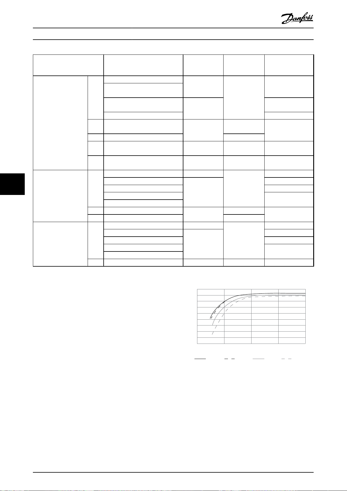
1.0
0.99
0.98
0.97
0.96
0.95
0.93
0.92
0% 50% 100% 200%
0.94
Relative Eciency
130BB252.11
1.01
150%
% Speed
100% load 75% load 50% load 25% load
Specications
VLT® Midi Drive FC 280
Non-UL circuit
Enclosure size Power [kW (hp)] Non-UL fuse
0.37 (0.5)
0.55–0.75
K1
3-phase 380–480 V
77
3-phase 200–240 V
Single-phase 200–240 V
K2
K3 7.5 (10) PKZM0-25
K4
K5
K1
K2 2.2 (3.0)
K3 3.7 (5.0) PKZM0-25
K1
K2 2.2 (3.0) gG-25 PKZM0-20 JJN-25
(0.74–1.0)
1.1–1.5
(1.48–2.0)
2.2 (3.0) JJS-15
3.0–5.5
(4.0–7.5)
11–15
(15–20)
18.5–22
(25–30)
0.37 (0.5) gG-10
0.55 (0.74)
0.75 (1.0) JJN-15
1.1 (1.48)
1.5 (2.0)
0.37 (0.5) gG-10
0.55 (0.74)
0.75 (1.0) JJN-15
1.1 (1.48)
1.5 (2.0)
gG-10
gG-20
gG-25
gG-50 – JJS-50
gG-80 – JJS-80
gG-20
gG-25
gG-20
breaker
(Eaton)
PKZM0-16
PKZM0-20
PKZM0-16
PKZM0-20
PKZM0-16
UL fuse
(Bussmann, class T)
JJS-6
JJS-10
JJS-25
JJN-6
JJN-10
JJN-20
JJN-25
JJN-6
JJN-10
JJN-20
Table 7.6 Fuse and Circuit Breaker
Eciency
7.9
Eciency of the frequency converter (η
The load on the frequency converter has little eect on its
eciency. In general, the eciency is the same at the
rated motor frequency f
. This rule also applies even if
M,N
the motor supplies 100% of the rated shaft torque or only
75%, for example if there is part loads.
This also means that the eciency of the frequency
converter does not change even if other U/f characteristics
are selected.
However, the U/f characteristics inuence the eciency of
the motor.
The eciency declines a little when the switching
frequency is set to a value above the default value. If the
mains voltage is 480 V, or if the motor cable is longer than
30 m (98.4 ft), the eciency is also slightly reduced.
Frequency converter eciency calculation
Calculate the eciency of the frequency converter at
dierent loads based on Illustration 7.2. Multiply the factor
in Illustration 7.2 by the specic eciency factor listed in
the specication tables in chapter 7.1 Electrical Data:
90 Danfoss A/S © 05/2017 All rights reserved. MG07B302
)
VLT
Illustration 7.2 Typical Eciency Curves
Eciency of the motor (η
MOTOR
)
The eciency of a motor connected to the frequency
converter depends on the magnetizing level. In general,
the eciency is as good as with mains operation. The
eciency of the motor depends on the type of motor.
In the range of 75–100% of the rated torque, the eciency
of the motor is practically constant, both when controlled
by the frequency converter and when running directly on
mains.

Specications Design Guide
In small motors, the inuence from the U/f characteristic
on eciency is marginal. However, in motors from 11 kW
(14.8 hp) and up, the advantages are signicant.
In general, the switching frequency does not aect the
eciency of small motors. Motors from 11 kW (14.8 hp)
and up have their eciency improved 1–2% because the
sine shape of the motor current is almost perfect at high
switching frequency.
Eciency of the system (η
SYSTEM
)
To calculate the system eciency, the eciency of the
frequency converter (η
the motor (η
η
SYSTEM
= η
VLT
MOTOR
x η
MOTOR
) is multiplied by the eciency of
VLT
):
7.10 Acoustic Noise
The acoustic noise from the frequency converter comes
from 3 sources:
DC intermediate circuit coils.
•
Integral fan.
•
RFI lter choke.
•
The typical values measured at a distance of 1 m (3.3 ft)
from the unit:
Enclosure size
[kW (hp)]
K1
0.37–2.2
(0.5–3.0)
K2
3.0–5.5 (4.0–7.5)
K3
7.5 (10)
K4
11–15 (15–20)
K5
18.5–22 (25–30)
Table 7.7 Typical Measured Values
80% fan
speed [dBA]
41.4 42.7 33
50.3 54.3 32.9
51 54.2 33
59 61.1 32.9
64.6 65.6 32.9
Full fan speed
[dBA]
Background
noise
If the peak voltage is too high, motors without phase coil
insulation are aected. The longer the motor cable, the
higher the rise time and peak voltage.
Switching of the IGBTs cause peak voltage on the motor
terminals. The VLT® Midi Drive FC 280 complies with IEC
60034-25 regarding motors designed to be controlled by
frequency converters. The FC 280 also complies with IEC
60034-17 regarding Norm motors controlled by frequency
converters.
The following dU/dt data are measured at the motor
terminal side:
Cable
length
[m (ft)]
5 (16.4) 400 0.0904 0.718 6.41
50 (164) 400 0.292 1.05 2.84
5 (16.4) 480 0.108 0.835 6.20
50 (164) 480 0.32 1.25 3.09
Table 7.8 dU/dt Data for FC 280, 2.2 kW (3.0 hp), 3x380–480 V
Cable
length
[m (ft)]
5 (16.4) 400 0.096 0.632 5.31
50 (164) 400 0.306 0.99 2.58
5 (16.4) 480 0.118 0.694 4.67
50 (164) 480 0.308 1.18 3.05
Table 7.9 dU/dt Data for FC 280, 5.5 kW (7.5 hp), 3x380–480 V
Cable
length
[m (ft)]
5 (16.4) 400 0.128 0.732 4.54
50 (164) 400 0.354 1.01 2.27
5 (16.4) 480 0.134 0.835 5.03
50 (164) 480 0.36 1.21 2.69
Mains
voltage
[V]
Mains
voltage
[V]
Mains
voltage
[V]
Rise time
[μsec]
Rise time
[μsec]
Rise time
[μsec]
U
[kV]
U
[kV]
U
[kV]
PEAK
PEAK
PEAK
dU/dt
[kV/μsec]
dU/dt
[kV/μsec]
dU/dt
[kV/μsec]
7 7
dU/dt Conditions
7.11
When a transistor in the frequency converter bridge
switches, the voltage across the motor increases by a
dU/dt ratio depending on the following factors:
The motor cable type.
•
The cross-section of the motor cable.
•
The length of the motor cable.
•
Whether the motor cable is shielded or not.
•
Inductance.
•
The natural induction causes an overshoot U
PEAK
in the
Table 7.10 dU/dt Data for FC 280, 7.5 kW (10 hp), 3x380–480 V
Cable
length
[m (ft)]
5 (16.4) 400 0.26 0.84 2.57
50 (164) 400 0.738 1.07 1.15
5 (16.4) 480 0.334 0.99 2.36
50 (164) 480 0.692 1.25 1.44
Table 7.11 dU/dt Data for FC 280, 15 kW (20 hp), 3x380–480 V
Mains
voltage
[V]
Rise time
[μsec]
U
PEAK
[kV]
dU/dt
[kV/μsec]
motor voltage before it stabilizes itself at a level
depending on the voltage in the DC link. The rise time and
the peak voltage U
MG07B302 Danfoss A/S © 05/2017 All rights reserved. 91
aect the service life of the motor.
PEAK

Specications
VLT® Midi Drive FC 280
Cable
length
[m (ft)]
5 (16.4) 400 0.258 0.652 2.01
50 (164) 400 0.38 1.03 2.15
5 (16.4) 480 0.258 0.752 2.34
50 (164) 480 0.4 1.23 2.42
Mains
voltage
[V]
Rise time
[μsec]
U
PEAK
[kV]
dU/dt
[kV/μsec]
Special Conditions
7.12
Under some special conditions, where the operation of the
frequency converter is challenged, consider derating. In
some conditions, derating must be done manually.
In other conditions, the frequency converter automatically
performs a degree of derating when necessary. Derating is
done to ensure the performance at critical stages where
Table 7.12 dU/dt Data for FC 280, 22 kW (30 hp), 3x380–480 V
Cable
length
[m (ft)]
5 (16.4) 240 0.0712 0.484 5.44
50 (164) 240 0.224 0.594 2.11
Table 7.13 dU/dt Data for FC 280, 1.5 kW (2.0 hp), 3x200–240 V
77
Cable
length
[m (ft)]
5 (16.4) 240 0.072 0.468 5.25
50 (164) 240 0.208 0.592 2.28
Table 7.14 dU/dt Data for FC 280, 2.2 kW (3.0 hp), 3x200–240 V
Mains
voltage
[V]
Mains
voltage
[V]
Rise time
[μsec]
Rise time
[μsec]
U
PEAK
[kV]
U
PEAK
[kV]
dU/dt
[kV/μsec]
dU/dt
[kV/μsec]
the alternative could be a trip.
Cable
length
[m (ft)]
5 (16.4) 240 0.092 0.526 4.56
50 (164) 240 0.28 0.6 1.72
Table 7.15 dU/dt Data for FC 280, 3.7 kW (5.0 hp), 3x200–240 V
Cable
length
[m (ft)]
5 (16.4) 240 0.088 0.414 3.79
50 (164) 240 0.196 0.593 2.41
Table 7.16 dU/dt Data for FC 280, 1.5 kW (2.0 hp), 1x200–240 V
Cable
length
[m (ft)]
5 (16.4) 240 0.112 0.368 2.64
50 (164) 240 0.116 0.362 2.51
Table 7.17 dU/dt Data for FC 280, 2.2 kW (3.0 hp), 1x200–240 V
Mains
voltage
[V]
Mains
voltage
[V]
Mains
voltage
[V]
Rise time
[μsec]
Rise time
[μsec]
Rise time
[μsec]
U
PEAK
[kV]
U
PEAK
[kV]
U
PEAK
[kV]
dU/dt
[kV/μsec]
dU/dt
[kV/μsec]
dU/dt
[kV/μsec]
92 Danfoss A/S © 05/2017 All rights reserved. MG07B302

0%
0 2 4 6 8 10 12 14 16
10%
20%
30%
40%
50%
60%
70%
80%
90%
100%
Switching Frequency [kHz]
Output Current
45C
50C
55C
130BE889.10
(1)
(2)
0%
0 2 4 6 8 10 12 14 16
10%
20%
30%
40%
50%
60%
70%
80%
90%
100%
45C
50C
55C
130BE890.10
(1) Output Current
(2) Switching Frequency [kHz]
0%
0 2 4 6 8 10 12 14 16
10%
20%
30%
40%
50%
60%
70%
80%
90%
100%
45C
50C
55C
130BE891.10
(2) Switching Frequency [kHz]
(1) Output Current
0%
0 2 4 6 8 10 12 14 16
10%
20%
30%
40%
50%
60%
70%
80%
90%
100%
45C
50C
55C
130BE892.10
(2) Switching Frequency [kHz]
(1) Output Current
Specications Design Guide
7.12.1 Manual Derating
Manual derating must be considered for:
Air pressure – for installation at altitudes above
•
1000 m (3281 ft).
Motor speed – at continuous operation at low
•
RPM in constant torque applications.
Ambient temperature – above 45 °C (113 °F), for
•
details, see from Illustration 7.3 to Illustration 7.12.
(1) Output current
(2) Switching frequency [kHz]
(1) Output current
(2) Switching frequency [kHz]
Illustration 7.3 K1T4 Derating Curve
Illustration 7.5 K3T4 Derating Curve
(1) Output current
(2) Switching frequency [kHz]
Illustration 7.6 K4T4 Derating Curve
7 7
(1) Output current
(2) Switching frequency [kHz]
Illustration 7.4 K2T4 Derating Curve
MG07B302 Danfoss A/S © 05/2017 All rights reserved. 93

0%
0 2 4 6 8 10 12 14 16
10%
20%
30%
40%
50%
60%
70%
80%
90%
100%
45C
50C
55C
130BE893.10
(1) Output Current
(2) Switching Frequency [kHz]
0%
0 2 4 6 8 10 12 14 16
10%
20%
30%
40%
50%
60%
70%
80%
90%
100%
45C
50C
55C
130BF104.10
(1) Output Current
(2) Switching Frequency [kHz]
0%
0 2 4 6 8 10 12 14 16
10%
20%
30%
40%
50%
60%
70%
80%
90%
100%
45C
50C
55C
130BF105.10
(1) Output Current
(2) Switching Frequency [kHz]
0%
0 2 4 6 8 10 12 14 16
10%
20%
30%
40%
50%
60%
70%
80%
90%
100%
45C
50C
55C
130BF106.10
(1) Output Current
(2) Switching Frequency [kHz]
0%
0 2 4 6 8 10 12 14 16
10%
20%
30%
40%
50%
60%
70%
80%
90%
100%
45C
50C
55C
130BF107.10
(1) Output Current
(2) Switching Frequency [kHz]
Specications
VLT® Midi Drive FC 280
(1) Output current
(2) Switching frequency [kHz]
(1) Output current
(2) Switching frequency [kHz]
Illustration 7.7 K5T4 Derating Curve
Illustration 7.10 K3T2 Derating Curve
77
(1) Output current
(2) Switching frequency [kHz]
Illustration 7.8 K1T2 Derating Curve
(1) Output current
(2) Switching frequency [kHz]
(1) Output current
(2) Switching frequency [kHz]
Illustration 7.9 K2T2 Derating Curve
94 Danfoss A/S © 05/2017 All rights reserved. MG07B302
Illustration 7.11 K1S2 Derating Curve

0%
0 2 4 6 8 10 12 14 16
10%
20%
30%
40%
50%
60%
70%
80%
90%
100%
45C
50C
55C
130BF107.10
(1) Output Current
(2) Switching Frequency [kHz]
Specications Design Guide
(1) Output current
(2) Switching frequency [kHz]
Illustration 7.12 K2S2 Derating Curve
NOTICE
Rated switching frequency is 6 kHz for K1–K3, 5 kHz for
K4–K5.
7 7
7.12.2 Automatic Derating
The frequency converter constantly checks for critical
levels:
Critical high temperature on the heat sink.
•
High motor load.
•
Low motor speed.
•
Protection signals (overvoltage/undervoltage,
•
overcurrent, ground fault, and short circuit) are
triggered.
As a response to a critical level, the frequency converter
adjusts the switching frequency.
MG07B302 Danfoss A/S © 05/2017 All rights reserved. 95

Specications
VLT® Midi Drive FC 280
7.13 Enclosure Sizes, Power Ratings, and Dimensions
Enclosure size K1 K2 K3 K4 K5
Single-phase
200–240 V
Power size
[kW (hp)]
77
Dimensions
[mm (in)]
Weight
[kg (lb)]
Mounting
holes [mm
(in)]
3-phase
200–240 V
3-phase
380–480 V
Height A1 210 (8.3) 272.5 (10.7)
Height A2 278 (10.9) 340 (13.4)
Width B 75 (3.0) 90 (3.5) 115 (4.5) 133 (5.2) 150 (5.9)
Depth C 168 (6.6) 168 (6.6) 168 (6.6) 245 (9.6) 245 (9.6)
Height A 338.5 (13.3) 395 (15.6)
Width B 100 (3.9) 115 (4.5) 130 (5.1) 153 (6.0) 170 (6.7)
Depth C 183 (7.2) 183 (7.2) 183 (7.2) 260 (10.2) 260 (10.2)
Height A 294 (11.6) 356 (14)
Width B 75 (3.0) 90 (3.5) 115 (4.5) 133 (5.2) 150 (5.9)
Depth C 168 (6.6) 168 (6.6) 168 (6.6) 245 (9.6) 245 (9.6)
IP20 2.5 (5.5) 3.6 (7.9)
IP21 4.0 (8.8) 5.5 (12.1)
a 198 (7.8) 260 (10.2)
b 60 (2.4) 70 (2.8) 90 (3.5) 105 (4.1) 120 (4.7)
c 5 (0.2) 6.4 (0.25)
d 9 (0.35) 11 (0.43) 11 (0.43) 12.4 (0.49) 12.6 (0.5)
e 4.5 (0.18) 5.5 (0.22)
f 7.3 (0.29) 8.1 (0.32)
0.37
(0.5)
0.37
(0.5)
0.37
(0.5)
0.55
(0.75)
0.55
(0.75)
0.55
(0.75)
0.75
1.1
(1.0)
(1.5)
0.75
1.1
(1.0)
(1.5)
0.75
1.1
(1.0)
(1.5)
FC 280 with IP21/UL/Type 1 kit
FC 280 with bottom cable entry cover (w/o top cover)
1.5
(2.0)
1.5
(2.0)
1.5
(2.0)
FC 280 IP20
2.2
(3.0)
3
(4.0
(3.0)
(3.0)
(5.5)
)
4
2.2
2.2
5.5
(7.5)
– – –
3.7
(5.0)
7.5
(10)11(15)15(20)
272.5
(10.7)
341.5
(13.4)
395
(15.6)
357
(14.1)
4.6
(10.1)
6.5
(14.3)
260
(10.2)
6.5
(0.26)
5.5
(0.22)
9.2
(0.36)
– –
317.5
(12.5)
379.5
(14.9)
425 (16.7) 520 (20.5)
391 (15.4) 486 (19.1)
8.2 (18.1) 11.5 (25.4)
10.5 (23.1) 14.0 (30.9)
297.5
(11.7)
8 (0.32) 7.8 (0.31)
6.8 (0.27) 7 (0.28)
11 (0.43) 11.2 (0.44)
18.5
(25)22(30)
410 (16.1)
474 (18.7)
390 (15.4)
Table 7.18 Enclosure Sizes, Power Ratings, and Dimensions
96 Danfoss A/S © 05/2017 All rights reserved. MG07B302

130BE844.11
B
C
A1
A2
130BE846.10
B
A
C
Specications Design Guide
7 7
Illustration 7.13 Standard with Decoupling Plate
Illustration 7.14 Standard with Bottom Cable Entry Cover (w/o Top Cover)
MG07B302 Danfoss A/S © 05/2017 All rights reserved. 97

B
C
A
130BE845.10
C
a
b
130BA648.12
f
e
B
A
a
d
e
b
c
Specications
VLT® Midi Drive FC 280
77
Illustration 7.15 Standard with IP21/UL/Type 1 kit
Illustration 7.16 Top and Bottom Mounting Holes
98 Danfoss A/S © 05/2017 All rights reserved. MG07B302
 Loading...