

ENGINEERING TOMORROW
Programming Guide
VLT® Midi Drive FC 280
vlt-drives.danfoss.com


Contents Programming Guide
Contents
1 Introduction
1.1 How to Read This Programming Guide
1.2 Denitions
1.3 Electrical Wiring - Control Cables
2 Safety
2.1 Safety Symbols
2.2 Qualied Personnel
2.3 Safety Precautions
3 Programming
3.1 Local Control Panel Operation
3.1.1 Numeric Local Control Panel (NLCP) 14
3.1.2 The Right-key Function on NLCP 15
3.1.3 Quick Menu on NLCP 16
3.1.4 Main Menu on NLCP 18
3.1.5 Graphic Local Control Panel (GLCP) 20
3.1.6 Parameter Settings 21
3
3
4
8
12
12
12
12
14
14
3.1.7 Changing Parameter Settings with GLCP 21
3.1.8 Uploading/Downloading Data to/from the LCP 21
3.1.9 Restoring Default Settings with LCP 22
3.2 Basic Programming
3.2.2 PM Motor Set-up in VVC
3.2.3 Automatic Motor Adaptation (AMA) 24
+
4 Parameter Descriptions
4.1 Parameters: 0-** Operation and Display
4.2 Parameters: 1-** Load and Motor
4.3 Parameters: 2-** Brakes
4.4 Parameters: 3-** Reference/Ramps
4.5 Parameters: 4-** Limits/Warnings
4.6 Parameters: 5-** Digital In/Out
4.7 Parameters: 6-** Analog In/Out
4.8 Parameters: 7-** Controllers
4.9 Parameters: 8-** Communications and Options
4.10 Parameters: 9-** PROFIdrive
22
23
25
25
37
49
51
57
60
70
73
78
83
4.11 Parameters: 10-** CAN Fieldbus
4.12 Parameters: 12-** Ethernet
4.13 Parameters: 13-** Smart Logic Control
4.14 Parameters: 14-** Special Functions
MG07C402 Danfoss A/S © 02/2019 All rights reserved. 1
83
83
83
90

Contents
VLT® Midi Drive FC 280
4.15 Parameters: 15-** Drive Information
4.16 Parameters: 16-** Data Readouts
4.17 Parameters: 18-** Data Readouts 2
4.18 Parameters: 21-** Ext. Closed Loop
4.19 Parameters: 22-** Application Functions
4.20 Parameters: 30-** Special Features
4.21 Parameters: 31-** Special Option
4.22 Parameters: 32-** Motion Control Basic Settings
4.23 Parameters: 33-** Motion Control Adv. Settings
4.24 Parameters: 34-** Motion Control Data Readouts
4.25 Parameters: 37-** Application Settings
5 Parameter Lists
5.1 Introduction
5.2 Parameter Lists
6 Troubleshooting
6.1 Warnings and Alarms
96
98
102
103
105
107
107
108
108
110
111
113
113
116
136
136
Index
6.1.3 Warning/Alarm Messages 136
6.1.4 Warning and Alarm Code List 137
146
2 Danfoss A/S © 02/2019 All rights reserved. MG07C402
Introduction Programming Guide
1 Introduction
1.1 How to Read This Programming Guide
1.1.1 Purpose of the Manual
This programming guide provides information about
controlling the frequency converter, accessing parameters,
programming, and troubleshooting.
The programming guide is intended for use by
personnel who are familiar with the VLT® Midi Drive FC
280 frequency converter.
Read the instructions before programming and follow the
procedures in this manual.
VLT® is a registered trademark.
1.1.2 Additional Resources
Additional resources include:
VLT® Midi Drive FC 280 Operating Guide, provides
•
the necessary information for getting the
frequency converter up and running.
VLT® Midi Drive FC 280 Design Guide, provides
•
detailed technical information about the
frequency converter, customer design, and
applications.
Contact the local Danfoss supplier or go to
drives.danfoss.com/knowledge-center/technical-documentation/ to download the documentation.
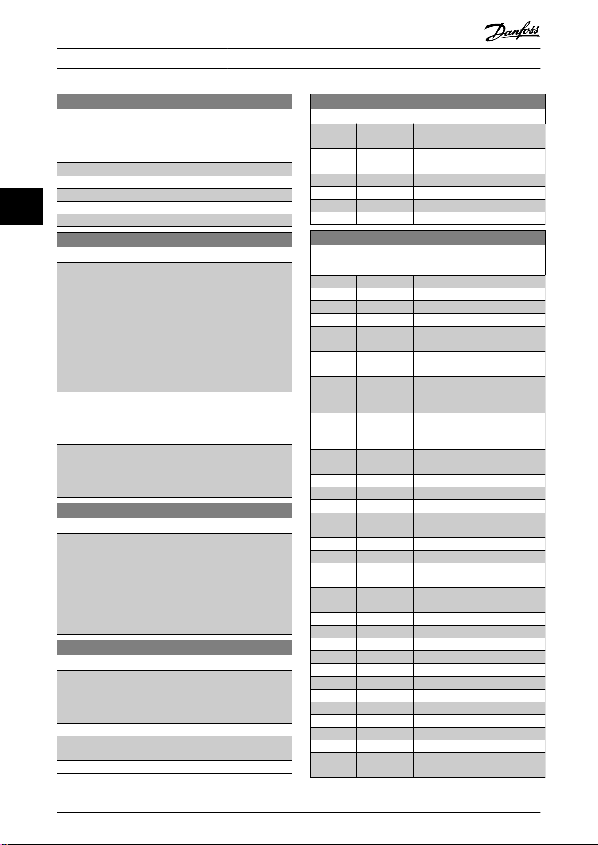
1.1.3 Document and Software Version
This manual is regularly reviewed and updated. All
suggestions for improvement are welcome. Table 1.1 shows
the document version and the corresponding software
version.
Edition Remarks Software
MG07C4 Update due to new software
version release.
Table 1.1 Document and Software Version
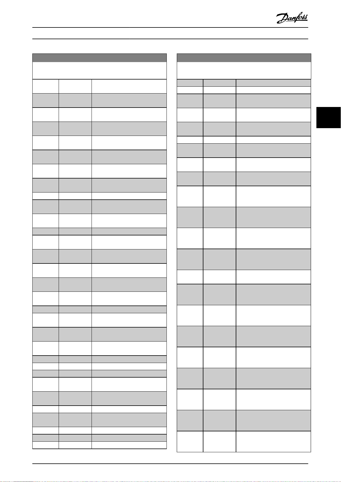
qualied
version
1.6
°C
°F
AC Alternating current
AEO Automatic energy optimization
ACP Application control processor
AWG American wire gauge
AMA Automatic motor adaptation
DC Direct current
EEPROM
EMC Electromagnetic compatibility
EMI Electromagnetic interference
ESD Electrostatic discharge
ETR Electronic thermal relay
f
M,N
FC Frequency converter
IGBT Insulated-gate bipolar transistor
IP Ingress protection
I
LIM
I
INV
I
M,N
I
VLT,MAX
I
VLT,N
L
d
L
q
LCP Local control panel
LED Light-emitting diode
MCP Motor control processor
N.A. Not applicable
NEMA
P
M,N
PCB Printed circuit board
PE Protective earth
PELV Protective extra low voltage
PWM Pulse width modulation
R
s
Regen Regenerative terminals
RPM Revolutions per minute
RFI Radio frequency interference
SCR Silicon controlled rectier
SMPS Switch mode power supply
T
LIM
U
M,N
X
h
Degrees Celsius
Fahrenheit
Electrically erasable programmable
read-only memory
Nominal motor frequency
Current limit
Rated inverter output current
Nominal motor current
Maximum output current
Rated output current supplied by the
frequency converter
Motor d-axis inductance
Motor q-axis inductance
National Electrical Manufacturers
Association
Nominal motor power
Stator resistance
Torque limit
Nominal motor voltage
Motor main reactance
1 1
Table 1.2 Abbreviations
MG07C402 Danfoss A/S © 02/2019 All rights reserved. 3
089
Introduction
VLT® Midi Drive FC 280
11
Denitions
1.2
1.2.1 Frequency Converter
Coast
The motor shaft is in free mode. No torque on the motor.
I
VLT,MAX
Maximum output current.
I
VLT,N
Rated output current supplied by the frequency converter.
U
VLT,MAX
Maximum output voltage.
1.2.2 Input
For compliance with the European Agreement concerning
International Carriage of Dangerous Goods by Inland
Waterways (ADN), refer to the chapter ADN-compliant Instal-
®
lation in the VLT
The frequency converter complies with UL 508C thermal
memory retention requirements. For more information,
refer to the chapter Motor Thermal Protection in the VLT
Midi Drive FC 280 Design Guide.
Applied standards and compliance for STO
Using STO on terminals 37 and 38 requires fulllment of all
provisions for safety including relevant laws, regulations,
and guidelines. The integrated STO function complies with
the following standards:
IEC/EN 61508:2010, SIL2
•
IEC/EN 61800-5-2:2007, SIL2
•
IEC/EN 62061:2015, SILCL of SIL2
•
EN ISO 13849-1:2015, Category 3 PL d
•
Midi Drive FC 280 Design Guide.
®
Control commands
Start and stop the connected motor with the LCP and
digital inputs.
Functions are divided into 2 groups.
Functions in group 1 have higher priority than functions in
group 2.
Group 1 Precise stop, coast stop, precise stop and coast
stop, quick stop, DC braking, stop, and [OFF].
Group 2 Start, pulse start, start reversing, jog, freeze
output, and [Hand On].
Table 1.3 Function Groups
4 Danfoss A/S © 02/2019 All rights reserved. MG07C402

175ZA078.10
Pull-out
RPM
Torque
Introduction Programming Guide
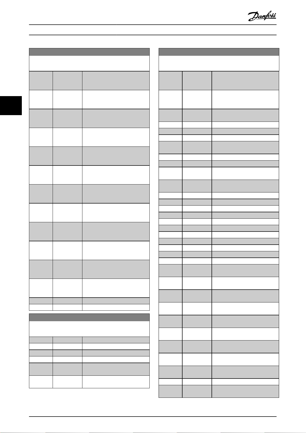
1.2.3 Motor
Motor running
Torque generated on the output shaft and speed from
0 RPM to maximum speed on the motor.
f
JOG
Motor frequency when the jog function is activated (via
digital terminals or bus).
f
M
Motor frequency.
f
MAX
Maximum motor frequency.
f
MIN
Minimum motor frequency.
f
M,N
Rated motor frequency (nameplate data).
I
M
Motor current (actual).
I
M,N
Nominal motor current (nameplate data).
n
M,N
Nominal motor speed (nameplate data).
n
s
Synchronous motor speed.
2 × Parameter 1−23 × 60s
ns=
n
slip
Motor slip.
P
M,N
Rated motor power (nameplate data in kW or hp).
T
M,N
Rated torque (motor).
U
M
Instantaneous motor voltage.
U
M,N
Rated motor voltage (nameplate data).
Parameter 1−39
Break-away torque
Illustration 1.1 Break-away Torque
η
VLT
The eciency of the frequency converter is dened as the
ratio between the power output and the power input.
Start-disable command
A start-disable command belonging to the control
commands in group 1. See Table 1.3 for more details.
Stop command
A stop command belonging to the control commands in
group 1. See Table 1.3 for more details.
1.2.4 References
Analog reference
A signal transmitted to the analog inputs 53 or 54 can be
voltage or current.
Binary reference
A signal transmitted via the serial communication port.
Preset reference
A dened preset reference to be set from -100% to +100%
of the reference range. Selection of 8 preset references via
the digital terminals. Selection of 4 preset references via
the bus.
Pulse reference
A pulse frequency signal transmitted to the digital inputs
(terminal 29 or 33).
Ref
MAX
Determines the relationship between the reference input at
100% full scale value (typically 10 V, 20 mA) and the
resulting reference. The maximum reference value is set in
parameter 3-03 Maximum Reference.
Ref
MIN
Determines the relationship between the reference input at
0% value (typically 0 V, 0 mA, 4 mA) and the resulting
reference. The minimum reference value is set in
parameter 3-02 Minimum Reference.
1 1
MG07C402 Danfoss A/S © 02/2019 All rights reserved. 5

Introduction
VLT® Midi Drive FC 280
11
1.2.5 Miscellaneous
GLCP
The graphic local control panel (LCP 102) interface for
Analog inputs
The analog inputs are used for controlling various
functions of the frequency converter.
There are 2 types of analog inputs:
Current input, 0–20 mA and 4–20 mA.
•
Voltage input, 0 to +10 V DC.
•
Analog outputs
The analog outputs can supply a signal of 0–20 mA, or 4–
20 mA.
Automatic motor adaptation, AMA
The AMA algorithm determines the electrical parameters
for the connected motor at standstill.
Brake resistor
The brake resistor is a module capable of absorbing the
brake power generated in regenerative braking. This
regenerative brake power increases the intermediate circuit
voltage, and a brake chopper ensures that the power is
transmitted to the brake resistor.
CT characteristics
Constant torque characteristics used for all applications
such as conveyor belts, displacement pumps, and cranes.
Digital inputs
The digital inputs can be used for controlling various
functions of the frequency converter.
Digital outputs
The frequency converter features 2 solid-state outputs that
can supply a 24 V DC (maximum 40 mA) signal.
ETR
Electronic thermal relay is a thermal load calculation based
on present load and time. Its purpose is to estimate the
motor temperature.
FC standard bus
Includes RS485 bus with FC protocol or MC protocol. See
parameter 8-30 Protocol.
Initializing
If initializing is carried out (parameter 14-22 Operation Mode
or 2
nger reset), the frequency converter returns to the
default setting.
Intermittent duty cycle
An intermittent duty rating refers to a sequence of duty
cycles. Each cycle consists of an on-load and an o-load
period. The operation can be either periodic duty or nonperiodic duty.
LCP
The local control panel makes up a complete interface for
control and programming of the frequency converter. The
control panel is detachable and can be installed up to 3 m
(9.8 ft) from the frequency converter, that is, in a front
panel with the installation kit option.
control and programming of the frequency converter. The
display is graphic and the panel is used to show process
values. The GLCP has storing and copy functions.
NLCP
The numerical local control panel (LCP 21) interface for
control and programming of the frequency converter. The
display is numerical and the panel is used to show process
values. The NLCP has storing and copy functions.
lsb
Least signicant bit.
msb
Most signicant bit.
MCM
Short for mille circular mil, an American measuring unit for
cable cross-section. 1 MCM = 0.5067 mm2.
On-line/o-line parameters
Changes to on-line parameters are activated immediately
after the data value is changed. Press [OK] to activate
changes to o-line parameters.
Process PID
The PID control maintains speed, pressure, and
temperature by adjusting the output frequency to match
the varying load.
PCD
Process control data.
Power cycle
Switch o the mains until the display (LCP) is dark, then
turn power on again.
Power factor
The power factor is the relation between I1 and I
Power factor =
3xUxI1cosϕ1
3xUxI
RMS
RMS
.
cosϕ1 = 1, therefore:
Power factor =
I1xcosϕ1
I
RMS
=
I
I
RMS
1
The power factor indicates to which extent the frequency
converter imposes a load on the mains supply.
The lower the power factor, the higher the I
RMS
for the
same kW performance.
I
RMS
= I
+ I
1
5
+ I
2
+ .. + I
7
2
n
2
2
In addition, a high power factor indicates that the dierent
harmonic currents are low.
The built-in DC coils produce a high power factor,
minimizing the imposed load on the mains supply.
Pulse input/incremental encoder
An external, digital pulse transmitter used for feeding back
information on motor speed. The encoder is used in
applications where great accuracy in speed control is
required.
6 Danfoss A/S © 02/2019 All rights reserved. MG07C402

Introduction Programming Guide
RCD
Residual current device.
Set-up
Save parameter settings in 4 set-ups. Change among the 4
parameter set-ups and edit 1 set-up while this set-up is
inactive.
SFAVM
Acronym describing the switching pattern stator uxoriented asynchronous vector modulation.
Slip compensation
The frequency converter compensates for the motor slip by
giving the frequency a supplement that follows the
measured motor load, keeping the motor speed almost
constant.
Smart logic control (SLC)
The SLC is a sequence of user-dened actions executed
when the associated user-dened events are evaluated as
true by the smart logic controller (parameter group 13-**
Smart Logic Control).
STW
Status word.
THD
Total harmonic distortion states the total contribution of
harmonic distortion.
Thermistor
A temperature-dependent resistor placed where the
temperature is monitored (frequency converter or motor).
Trip
A state entered in fault situations, for example if the
frequency converter is subject to overvoltage or when it is
protecting the motor, process, or mechanism. Restart is
prevented until the cause of the fault has disappeared, and
the trip state is canceled by activating reset or, sometimes,
by being programmed to reset automatically. Do not use
trip for personal safety.
Trip lock
A state entered in fault situations when the frequency
converter is protecting itself and requiring physical
intervention, for example if the frequency converter is
subject to a short circuit on the output. A locked trip can
only be canceled by cutting o mains, removing the cause
of the fault, and reconnecting the frequency converter.
Restart is prevented until the trip state is canceled by
activating reset or, in some cases, by being programmed to
reset automatically. Do not use trip lock for personal safety.
VT characteristics
Variable torque characteristics used for pumps and fans.
+
VVC
If compared with standard voltage/frequency ratio control,
voltage vector control (VVC+) improves the dynamics and
stability, both when the speed reference is changed and in
relation to the load torque.
60° AVM
Refers to the switching pattern 60° asynchronous vector
modulation.
1 1
MG07C402 Danfoss A/S © 02/2019 All rights reserved. 7
Power
input
Switch mode
power supply
Motor
Analog output
interface
(PNP) = Source
(NPN) = Sink
ON = Terminated
OFF = Open
Brake
resistor
91 (L1/N)
92 (L2/L)
93 (L3)
PE
50 (+10 V OUT)
53 (A IN)
2)
54 (A IN)
55 (COM digital/analog I/O)
0/4−20 mA
12 (+24 V OUT)
13 (+24 V OUT)
18 (D IN)
10 V DC
15 mA 100 mA
+ - + -
(U) 96
(V) 97
(W) 98
(PE) 99
(A OUT) 42
(P RS485) 68
(N RS485) 69
(COM RS485) 61
0 V
5 V
S801
0/4−20 mA
RS485
RS485
03
+10 V DC
0−10 V DC
24 V DC
02
01
24 V (NPN)
0 V (PNP)
0 V (PNP)
24 V (NPN)
19 (D IN)
24 V (NPN)
0 V (PNP)
17 V
0 V
0 V (PNP)
24 V (NPN)
29 (D IN)
24 V (NPN)
0 V (PNP)
0 V (PNP)
24 V (NPN)
33 (D IN)
32 (D IN)
38 (STO2)
4)
37 (STO1)
4)
95
P 5-00
21
ON
(+DC/R+) 89
(R-) 81
0−10 V DC
(-DC) 88
RFI
0 V
250 V AC, 3 A
Relay 1
1)
3)
5)
5)
130BE202.19
27 (D IN/OUT)
6)
Introduction
VLT® Midi Drive FC 280
11
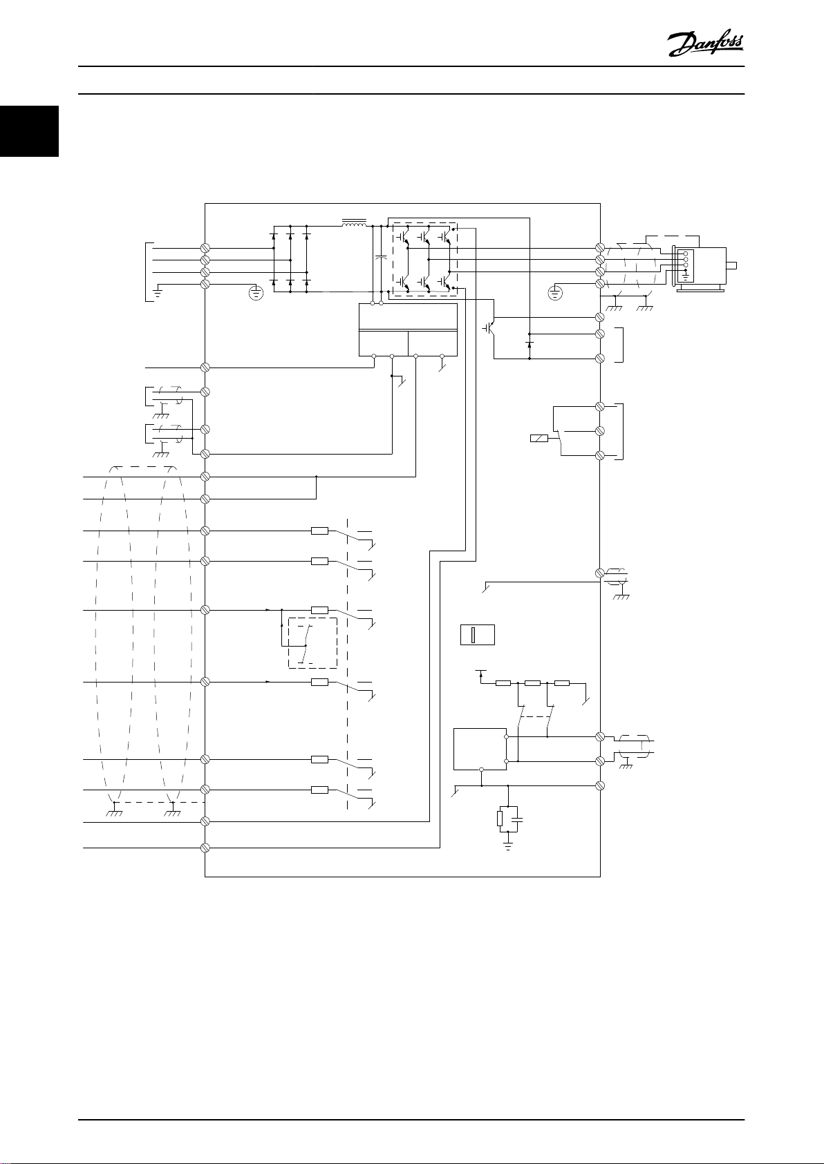
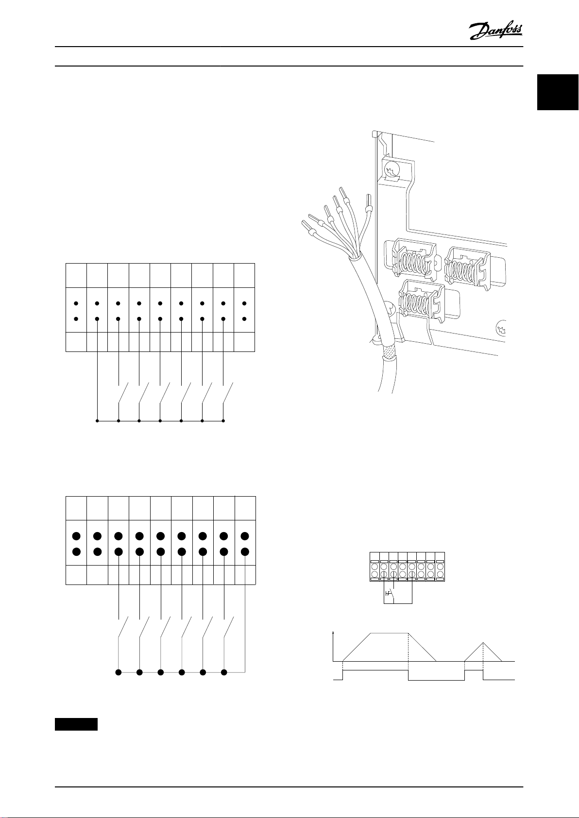
1.3 Electrical Wiring - Control Cables
1.3.1 Overview
Illustration 1.2 Basic Wiring Schematic Drawing
A=Analog, D=Digital
1) Built-in brake chopper is only available on 3-phase units.
2) Terminal 53 can also be used as digital input.
3) Switch S801 (bus terminal) can be used to enable termination on the RS485 port (terminals 68 and 69).
4) Refer to chapter 6 Safe Torque O (STO) in the operating guide for the correct STO wiring.
5) The S2 drive doesn’t support load sharing application.
8 Danfoss A/S © 02/2019 All rights reserved. MG07C402
130BE730.10
12 13 18 19 27 29 32 33 55
+24 VDC
0 VDC
PNP (Source)
Digital input wiring
NPN (Sink)
Digital input wiring
12 13 18 19 27 29 32 33 55
+24 VDC
0 VDC
130BE731.10
130BA681.10
130BE732.11
12 13 18 322719 29 33
P 5-12 [2]
P 5-10 [8]
Start/Stop
+24V
Speed
Start
[18]
Introduction Programming Guide
In rare cases, long control cables and analog signals result
in 50/60 Hz ground loops due to noise from mains supply
cables. If this occurs, break the shield or insert a 100 nF
capacitor between shield and chassis.
Connect the digital and analog inputs and outputs
separately to the common inputs (terminal 55) of the
frequency converter to avoid that ground currents from
both groups aect other groups. For example, switching
on the digital input could disturb the analog input signal.
Input polarity of control terminals
See the section Using Shielded Control Cables in the design
guide for the correct termination of control cables.
1 1
Illustration 1.3 PNP (Source)
Illustration 1.4 NPN (Sink)
Illustration 1.5 Grounding of Shielded/Armored Control Cables
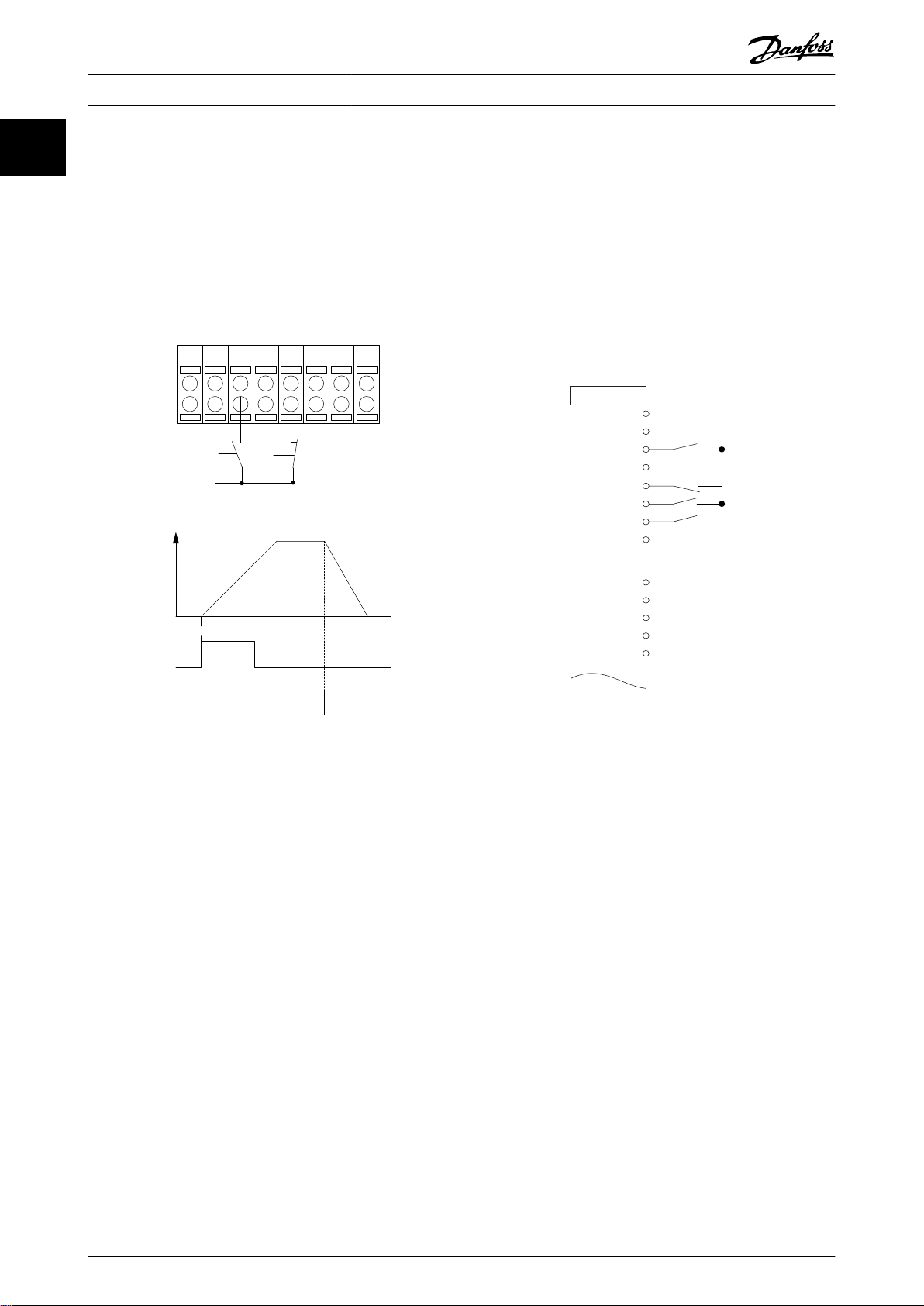
1.3.2 Start/Stop
Terminal 18 = Parameter 5-10 Terminal 18 Digital Input [8]
Start.
Terminal 27 = Parameter 5-12 Terminal 27 Digital Input [0]
No operation (Default coast inverse).
Illustration 1.6 Start/Stop
NOTICE
Control cables must be shielded/armored.
MG07C402 Danfoss A/S © 02/2019 All rights reserved. 9
1312 18 19 322927 33
P 5 - 12 [6]
P 5 - 10 [9]
+24 V
Speed
Latched start Stop inverse
Latched start (18)
Stop inverse (27)
130BF101.11
FC
+24 V
+24 V
D IN
D IN
D IN
D IN
D IN
D IN
+10 V
A IN
A IN
COM
A OUT
12
13
18
19
27
29
32
33
50
53
54
55
42
130BF095.10
Introduction
VLT® Midi Drive FC 280
11
1.3.3 Latched Start/Stop Inverse
Terminal 18 = Parameter 5-10 Terminal 18 Digital Input [9]
Latched start.
Terminal 27 = Parameter 5-12 Terminal 27 Digital Input [6]
Stop inverse.
1.3.4 Speed Up/Down
Terminals 29/32 = Speed up/down
Terminal 18 = Parameter 5-10 Terminal 18 Digital
Input [9] Start (default).
Terminal 27 = Parameter 5-12 Terminal 27 Digital
Input [19] Freeze reference.
Terminal 29 = Parameter 5-13 Terminal 29 Digital
Input [21] Speed up.
Terminal 32 = Parameter 5-14 Terminal 32 Digital
Input [22] Speed down.
Illustration 1.8 Speed Up/Down
Illustration 1.7 Latched Start/Stop Inverse
10 Danfoss A/S © 02/2019 All rights reserved. MG07C402
130BD381.12
555342 54 50
Speed
P 6-15
1 kΩ
+10V/15mA
Ref. voltage
P 6-11 10V
Introduction Programming Guide
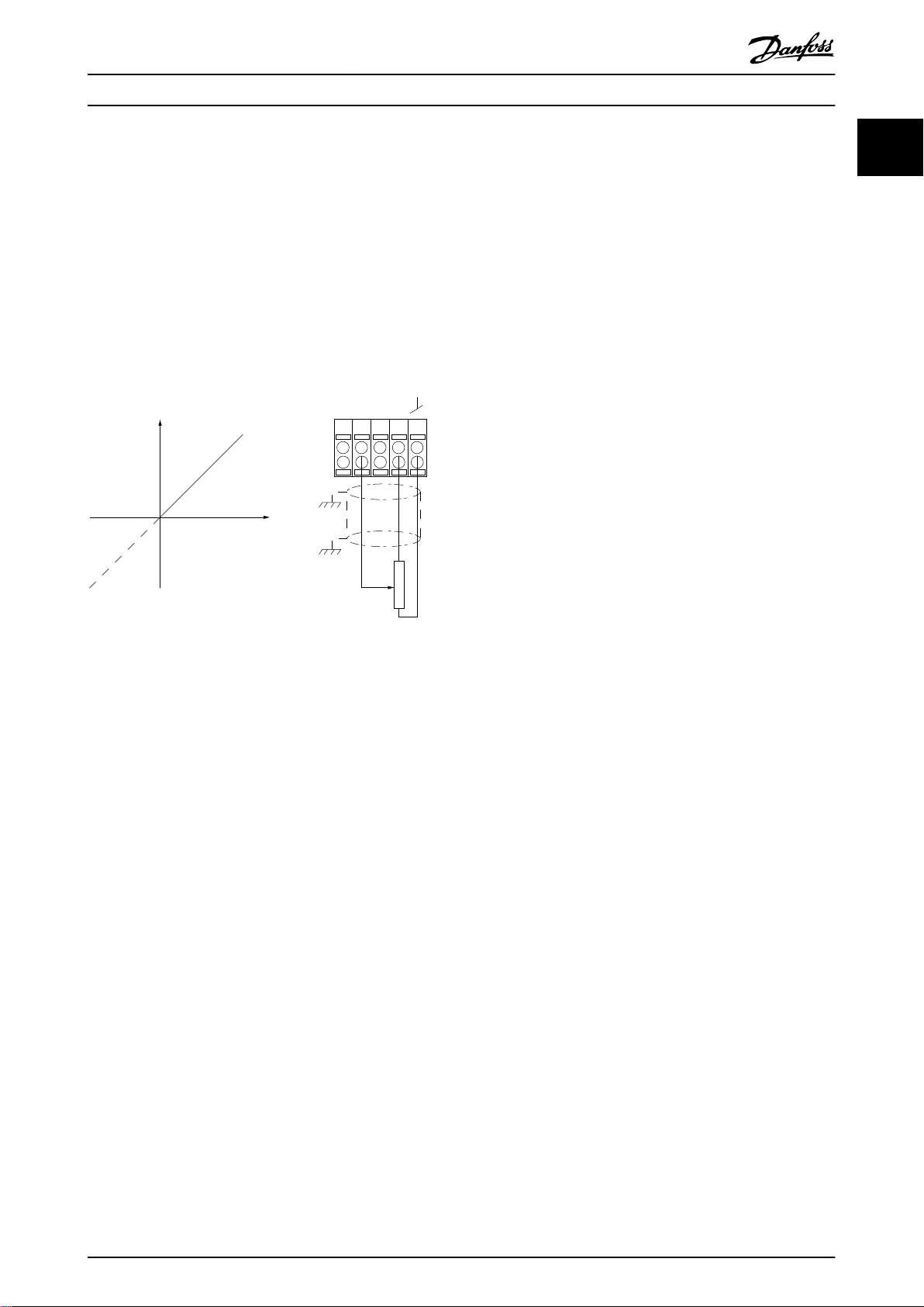
1.3.5 Potentiometer Reference
Voltage reference via a potentiometer
Reference source 1 = [1] Analog input 53 (default).
Terminal 53, low voltage = 0 V.
Terminal 53, high voltage = 10 V.
Terminal 53, low ref./feedback = 0 Hz.
Terminal 53, high ref./feedback = 50 Hz.
Parameter 6-19 Terminal 53 mode = [1] Voltage.
1 1
Illustration 1.9 Potentiometer Reference
MG07C402 Danfoss A/S © 02/2019 All rights reserved. 11
Safety
VLT® Midi Drive FC 280
2 Safety
22
2.1 Safety Symbols
The following symbols are used in this document:
WARNING
Indicates a potentially hazardous situation that could
result in death or serious injury.
CAUTION
Indicates a potentially hazardous situation that could
result in minor or moderate injury. It can also be used to
alert against unsafe practices.
NOTICE
Indicates important information, including situations that
can result in damage to equipment or property.
2.2 Qualied Personnel
Correct and reliable transport, storage, installation,
operation, and maintenance are required for the troublefree and safe operation of the frequency converter. Only
qualied personnel are allowed to install or operate this
equipment.
Qualied personnel are dened as trained sta, who are
authorized to install, commission, and maintain equipment,
systems, and circuits in accordance with pertinent laws and
regulations. Also, the personnel must be familiar with the
instructions and safety measures described in this guide.
Safety Precautions
2.3
WARNING
HIGH VOLTAGE
Drives contain high voltage when connected to AC mains
input, DC supply, or load sharing. Failure to perform
installation, start-up, and maintenance by qualied
personnel can result in death or serious injury.
Only qualied personnel must perform instal-
•
lation, start-up, and maintenance.
Before performing any service or repair work,
•
use an appropriate voltage measuring device to
make sure that there is no remaining voltage on
the drive.
WARNING
UNINTENDED START
When the frequency converter is connected to AC mains,
DC supply, or load sharing, the motor may start at any
time. Unintended start during programming, service, or
repair work can result in death, serious injury, or
property damage. The motor can start with an external
switch, a eldbus command, an input reference signal
from the LCP, via remote operation using MCT 10 Set-up
Software, or after a cleared fault condition.
To prevent unintended motor start:
Disconnect the frequency converter from the
•
mains.
Press [O/Reset] on the LCP before
•
programming parameters.
Completely wire and assemble the frequency
•
converter, motor, and any driven equipment
before connecting the frequency converter to
AC mains, DC supply, or load sharing.
WARNING
DISCHARGE TIME
The frequency converter contains DC-link capacitors,
which can remain charged even when the frequency
converter is not powered. High voltage can be present
even when the warning LED indicator lights are o.
Failure to wait the specied time after power has been
removed before performing service or repair work can
result in death or serious injury.
Stop the motor.
•
Disconnect AC mains and remote DC-link
•
supplies, including battery back-ups, UPS, and
DC-link connections to other frequency
converters.
Disconnect or lock PM motor.
•
Wait for the capacitors to discharge fully. The
•
minimum waiting time is specied in Table 2.1.
Before performing any service or repair work,
•
use an appropriate voltage measuring device to
make sure that the capacitors are fully
discharged.
12 Danfoss A/S © 02/2019 All rights reserved. MG07C402
Safety Programming Guide
Voltage [V]
200–240 0.37–3.7 (0.5–5) 4
380–480
Table 2.1 Discharge Time
Power range
[kW (hp)]
0.37–7.5 (0.5–10) 4
11–22 (15–30) 15
Minimum waiting time
(minutes)
WARNING
LEAKAGE CURRENT HAZARD
Leakage currents exceed 3.5 mA. Failure to ground the
drive properly can result in death or serious injury.
Ensure the correct grounding of the equipment
•
by a certied electrical installer.
WARNING
EQUIPMENT HAZARD
Contact with rotating shafts and electrical equipment
can result in death or serious injury.
Ensure that only trained and qualied personnel
•
perform installation, start-up, and maintenance.
Ensure that electrical work conforms to national
•
and local electrical codes.
Follow the procedures in this guide.
•
2 2
CAUTION
INTERNAL FAILURE HAZARD
An internal failure in the drive can result in serious injury
when the drive is not properly closed.
Ensure that all safety covers are in place and
•
securely fastened before applying power.
MG07C402 Danfoss A/S © 02/2019 All rights reserved. 13
130BC506.10
Setup 1
A
B
C
D
5
12
13 14 15
10
11
10
9
6
7
8
4
1
2
3
Menu
Status
Quick
Menu
Main
Menu
Hand
On
O
Reset
Auto
On
Back
OK
On
Warn
Alarm
130BD135.10
Setup 1234
INDEX
AHP
VkW
srpm
Hz%
n2n1
n3
p5 p4
p3 p2 p1
Programming
3 Programming
VLT® Midi Drive FC 280
3.1 Local Control Panel Operation
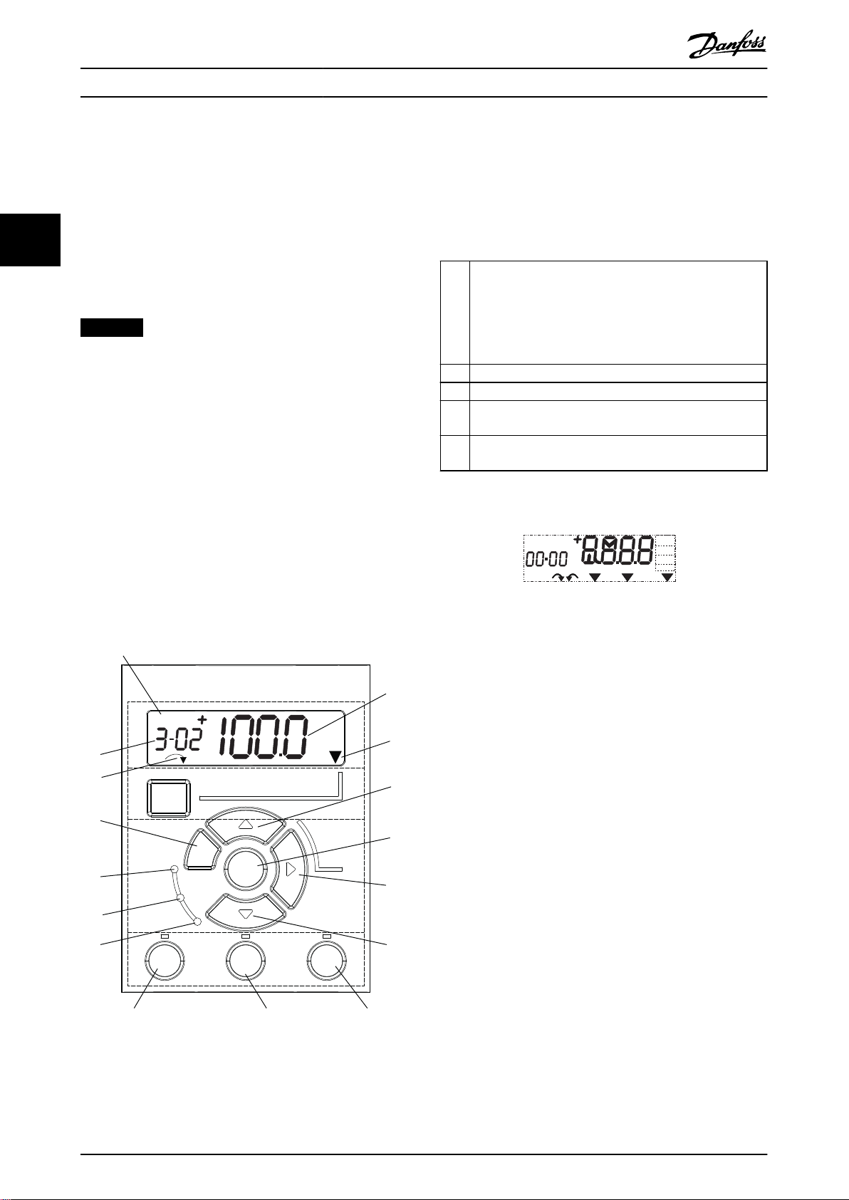
A. Numeric display
The LCD display is backlit with 1 numeric line. All data is
33
The frequency converter supports numerical local control
panel (NLCP), graphic local control panel (GLCP), and blind
cover. This section describes the operations with NLCP and
GLCP.
NOTICE
The frequency converter can also be programmed from
the MCT 10 Set-up Software on PC via RS485 communication port or USB port. This software can be ordered
using ordering number 130B1000 or downloaded from
the Danfoss website: drives.danfoss.com/downloads/pc-
tools/#/.
shown in the NLCP.
The set-up number shows the active set-up and the edit
set-up. If the same set-up acts as both active and edit setup, only that set-up number is shown (factory setting).
1
When active and edit set-up dier, both numbers are
shown in the display (for example set-up 12). The number
ashing indicates the edit set-up.
2 Parameter number.
3 Parameter value.
Motor direction is shown at the bottom left of the display.
4
A small arrow indicates the direction.
The triangle indicates whether the LCP is in Status, Quick
5
Menu, or Main Menu.
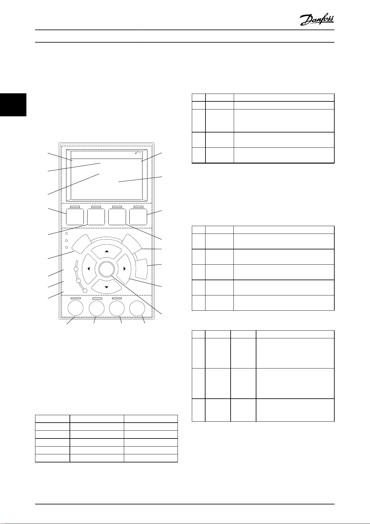
3.1.1 Numeric Local Control Panel (NLCP)
Table 3.1 Legend to Illustration 3.1, Section A
The numerical local control panel (NLCP) is divided into 4
functional sections.
A. Numeric display.
B. Menu key.
C. Navigation keys and indicator lights (LEDs).
D. Operation keys and indicator lights (LEDs).
Illustration 3.2 Display Information
B. Menu key
To select between Status, Quick Menu, or Main Menu,
press [Menu].
Illustration 3.1 View of the NLCP
14 Danfoss A/S © 02/2019 All rights reserved. MG07C402
130BC440.10
Setup 1
Setup 1
Setup 1
Setup 1
Setup 1
Programming Programming Guide
C. Indicator lights (LEDs) and navigation keys
Indicator Light Function
ON turns on when the frequency
6 On Green
7 Warn Yellow
8 Alarm Red
Table 3.2 Legend to Illustration 3.1, Indicator Lights (LEDs)
9 [Back]
10
11 [OK]
12
Key Function
[▲] [▼]
[►]
converter receives power from the
mains voltage, a DC bus terminal, or a
24 V external supply.
When warning conditions are met, the
yellow WARN LED turns on, and text
appears in the display area identifying
the problem.
A fault condition causes the red alarm
LED to ash and an alarm text is
shown.
For moving to the previous step or layer
in the navigation structure.
For switching between parameter groups,
parameters, and within parameters, or
increasing/decreasing parameter values.
Arrows can also be used for setting local
reference.
Press to access parameter groups or to
enable a selection.
Press to move from left to right within
the parameter value to change each digit
individually.
WARNING
ELECTRICAL HAZARD
Even after pressing the [O/Reset] key, voltage is present
at the terminals of the frequency converter. Pressing the
[O/Reset] key does not disconnect the frequency
converter from mains. Touching live parts can result in
death or serious injury.
Do not touch any live parts.
•
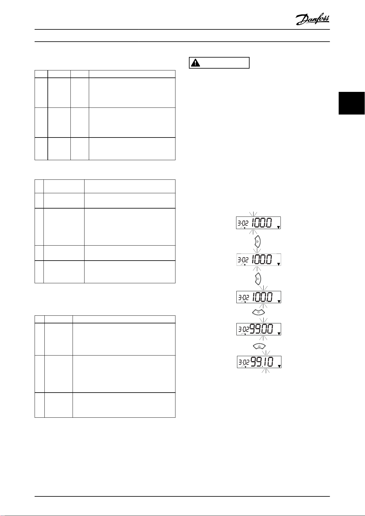
3.1.2 The Right-key Function on NLCP
Press [►] to edit any of the 4 digits on the display
individually. When pressing [►] once, the cursor moves to
the rst digit, and the digit starts ashing as shown in
Illustration 3.3. Press the [▲] [▼] to change the value.
Pressing [►] does not change the value of the digits, or
move the decimal point.
3 3
Table 3.3 Legend to Illustration 3.1, Navigation Keys
D. Operation keys and indicator lights (LEDs)
Key Function
Starts the frequency converter in local control.
An external stop signal by control input or
13 Hand On
14 O/Reset
15 Auto On
Table 3.4 Legend to Illustration 3.1, Section D
•
serial communication overrides the local
hand on.
Stops the motor but does not remove power
to the frequency converter or resets the
frequency converter manually after a fault has
been cleared. If in alarm mode, the alarm is
reset if the alarm condition is removed.
Puts the system in remote operational mode.
Responds to an external start command by
•
control terminals or serial communication.
Illustration 3.3 Right-key Function
[►] can also be used for moving between parameter
groups. When in Main Menu, press [►] to move to the rst
parameter in the next parameter group (for example, move
from parameter 0-03 Regional Settings [0] International to
parameter 1-00 Conguration Mode [0] Open loop).
MG07C402 Danfoss A/S © 02/2019 All rights reserved. 15

Programming
VLT® Midi Drive FC 280
NOTICE
During start-up, the NLCP shows the message LCP ON.
When this message is no longer shown, the frequency
converter is ready for operation. Adding or removing
options can extend the duration of start-up.
33
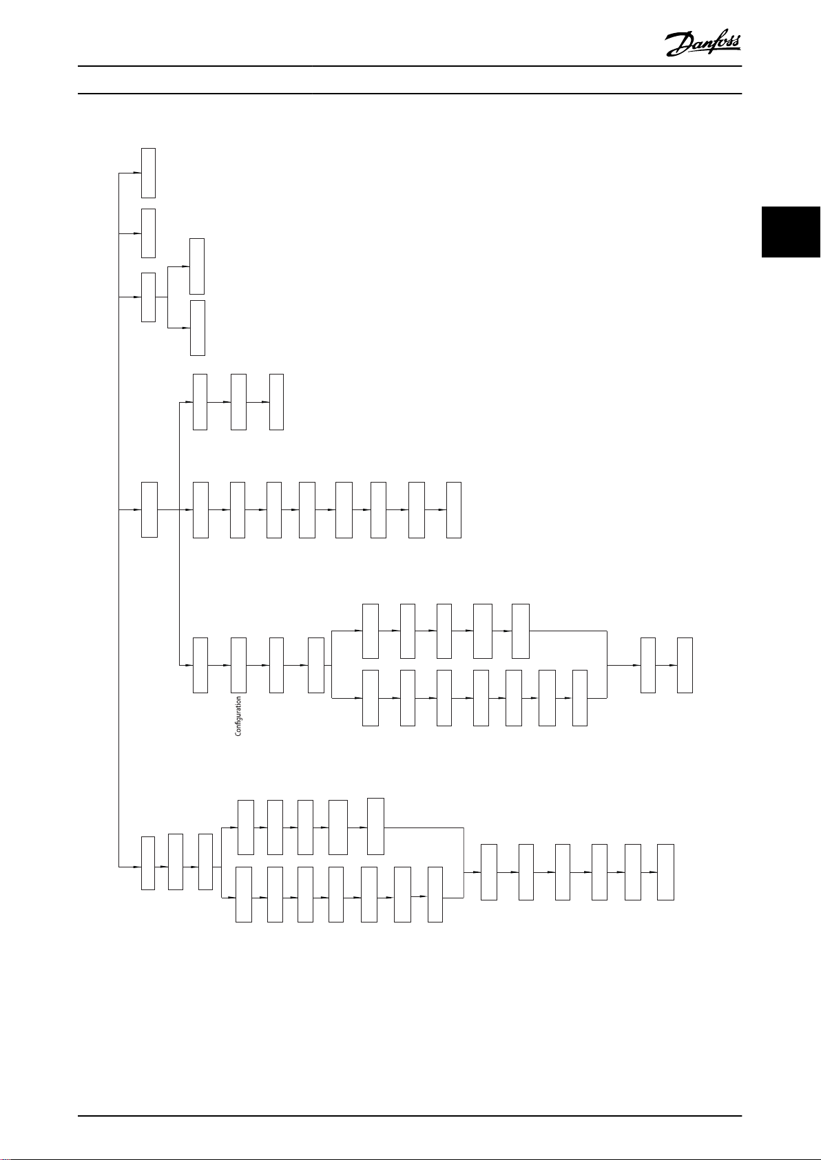
3.1.3 Quick Menu on NLCP
The Quick Menu gives easy access to the most frequently
used parameters.
1. To enter Quick Menu, press [Menu] until the
indicator in the display is placed above Quick
Menu.
2.
Press [▲] [▼] to select either QM1 or QM2, then
press [OK].
3.
Press [▲] [▼] to browse through the parameters in
Quick Menu.
4. Press [OK] to select a parameter.
5.
Press [▲] [▼] to change the value of a parameter
setting.
6. Press [OK] to accept the change.
7. To exit, press either [Back] twice (or 3 times if in
QM2 and QM3) to enter Status, or press [Menu]
once to enter Main Menu.
16 Danfoss A/S © 02/2019 All rights reserved. MG07C402
130BC445.13
1-22 XXXX V
Motor
nominal
speed
QM 1
0-01 [0]
1-10 [0]
1-24 XXXX A
Language
Motor Type
1-20 XXXX kW
Motor power
Motor voltage
1-26 XXXX 1-23 XXXX
Stator
Motor frequency
1-25 XXXX
1-30 XXXX
1-39 XXXX
1-40 XXXX
1-37 XXXX
1-25 XXXX
1-24 XXXX
A
3-02 XXXX
3-03 XXXX
3-41 XXXX S
3-42 XXXX S
5-12
[2]
1-29 [1]
AMA
Back EMF at
1000 RPM
d-axis
QM 2
BMS
AMS
ES
5-70 XXXX
5-71 [0]
1-30 XXXX
1-39 XXXX
1-90 [0]
2-10 [0]
4-16 XXXX %
4-17 XXXX %
4-18 XXXX %
1-00 [0]
1-01 [1]
1-10 [0]
1-24 XXXX A 1-20 XXXX kW
1-22 XXXX V
Motor
nominal
speed
Motor power
Motor voltage
1-26 XXXX 1-23 XXXX
Motor frequency
1-25 XXXX
1-30 XXXX
1-40 XXXX
1-37 XXXX
1-25 XXXX
1-24 XXXX
A
Back EMF at
1000 RPM
d-axis
1-39 XXXX
4-14 XXXX
4-19 XXXX
Stator
QM 3
QM 4 QM 5
L10C
SFS
TBD
Motor
nominal
speed
Motor
nominal
speed
Motor current
Motor cont.
rated torque
Resistance (Rs)
Motor poles
inductance (Ld)
Asynchronous motor
Motor current
Minimum reference
Maximum reference
Ramp 1 ramp-up time
Ramp 1 ramp-down time
Terminal 27 digital input
Basic motor set-up
mode
Motor control
principle
Motor type
PM motor
PM motor
Motor
current
Motor cont.
rated torque
Stator
Resistance (Rs)
Motor poles
inductance (Ld)
Motor speed high limit [Hz]
Maximum output frequency
Asynchronous motor
Motor current
RPM
RPM
RPM
Hz
RPM
Hz
Hz
Hz
Hz
Hz
Adv. motor set-up
Resistance (Rs)
Motor poles
Motor thermal
protection
Brake function
Torque limit motor mode
Torque limit generator mode
Current limit
Encoder set-up
Terminal 32/33
pulses per revolution
Terminal 32/33
encoder direction
Changes made
Last 10 changes Since factory setting
Alarm log
Programming Programming Guide
3 3
MG07C402 Danfoss A/S © 02/2019 All rights reserved. 17
Illustration 3.4 Quick Menu Structure
130BC446.10
Setup 1
Setup 1
Setup 1
Setup 1
Setup 1
Setup 1
Setup 1
Setup 1
1
2
3
4
5
6
7
10
11
12
OK
OK
Back
8
Back
Setup 1
2 x
+
OK
9
OK
Programming
VLT® Midi Drive FC 280
3.1.4 Main Menu on NLCP
The Main Menu gives access to all parameters.
1. To enter Main Menu, press [Menu] until the
33
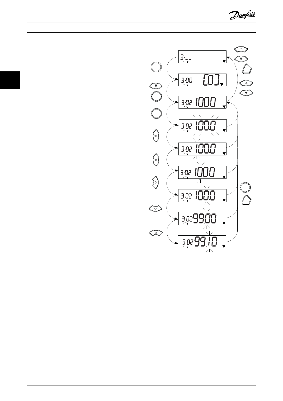
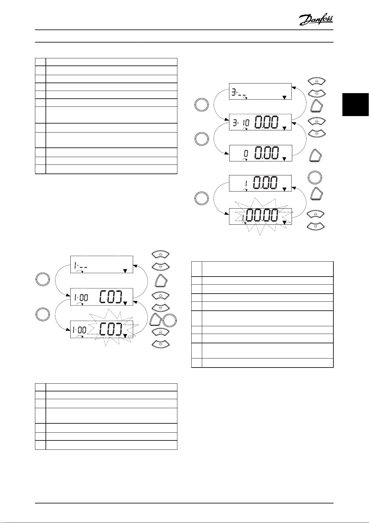
See Illustration 3.5, Illustration 3.6, and Illustration 3.7 for the
principles of changing the value of continuous,
enumerated, and array parameters, respectively. The
actions in the illustrations are described in Table 3.5,
Table 3.6, and Table 3.7.
indicator in the display is placed above Main
Menu.
2.
[▲] [▼]: Browse through the parameter groups.
3. Press [OK] to select a parameter group.
4.
[▲] [▼]: Browse through the parameters in the
specic group.
5. Press [OK] to select the parameter.
6.
[►] and [▲]/ [▼]: Set/change the parameter value.
7. Press [OK] to accept the value.
8. To exit, press either [Back] twice (or 3 times for
array parameters) to enter Main Menu, or press
[Menu] once to enter Status.
Illustration 3.5 Main Menu Interactions - Continuous
Parameters
18 Danfoss A/S © 02/2019 All rights reserved. MG07C402
130BC447.11
Setup 1
Setup 1
Setup 1
1
2
3
4
5
6
OK
OK
Back
7
OK
Back
130BC448.10
1
2
4
5
6
7
8
9
10
OK
Back
Back
Back
5 x
Setup 1
Setup 1
Setup 1
Setup 1
%
INDEX
%
INDEX
%
INDEX
Setup 1
INDEX
%
OK
OK
OK
Programming Programming Guide
1 [OK]: The rst parameter in the group is shown.
2
Press [▼] repeatedly to move down to the parameter.
3 Press [OK] to start editing.
4
[►]: First digit ashing (can be edited).
5
[►]: Second digit ashing (can be edited).
6
[►]: Third digit ashing (can be edited).
7
[▼]: Decrease the parameter value, the decimal point
changes automatically.
8
[▲]: Increase the parameter value.
9 [Back]: Cancel changes, return to 2.
[OK]: Accept changes, return to 2.
10
[▲][▼]: Select parameter within the group.
11 [Back]: Remove the value and show the parameter group.
12
[▲][▼]: Select group.
Table 3.5 Changing Values in Continuous Parameters
For enumerated parameters, the interaction is similar, but
the parameter value is shown in brackets because of the
digits limitation (4 large digits) on the NLCP, and the enum
can be greater than 99. When the enum value is greater
than 99, the LCP can only show the
rst part of the
bracket.
Array parameters function as follows:
3 3
Illustration 3.7 Main Menu Interactions - Array Parameters
1 [OK]: Show parameter numbers and the value in the rst
index.
2 [OK]: Index can be selected.
3
[▲][▼]: Select index.
4 [OK]: Value can be edited.
5
[▲][▼]: Change parameter value (ashing).
6 [Back]: Cancel changes.
[OK]: Accept changes.
7 [Back]: Cancel editing index, select a new parameter.
8
[▲][▼]: Select parameter within the group.
9 [Back]: Remove parameter index value and show the
Illustration 3.6 Main Menu Interactions - Enumerated
Parameters
1 [OK]: The rst parameter in the group is shown.
2 Press [OK] to start editing.
3
[▲][▼]: Change parameter value (ashing).
4 Press [Back] to cancel changes or [OK] to accept changes
(return to screen 2).
5
[▲][▼]: Select a parameter within the group.
6 [Back]: Remove the value and show the parameter group.
7
[▲][▼]: Select a group.
Table 3.6 Changing Values in Enumerated Parameters
MG07C402 Danfoss A/S © 02/2019 All rights reserved. 19
parameter group.
10
[▲][▼]: Select group.
Table 3.7 Changing Values in Array Parameters
130BD598.10
Auto
On
Reset
Hand
On
O
Status
Quick
Menu
Main
Menu
Alarm
Log
Back
Cancel
Info
OK
Status
1(1)
36.4 kW
Auto Remote Ramping
0.000
On
Alarm
Warn.
A
7.83 A
799 RPM
B
C
D
53.2 %
1
2
3
4
5
6
7
8
9
10
11
12
13
14
15
16
17
18 19 20 21
Programming
VLT® Midi Drive FC 280
3.1.5 Graphic Local Control Panel (GLCP)
B. Display menu keys
Menu keys are used for menu access for parameter set-up,
The GLCP is divided into 4 functional groups (see
Illustration 3.8).
33
A. Display area.
B. Display menu keys.
C. Navigation keys and indicator lights (LEDs).
D. Operation keys and reset.
toggling through status display modes during normal
operation, and viewing fault log data.
Key Function
6 Status Shows operational information.
Quick
7
Menu
8 Main Menu
9 Alarm Log
Table 3.9 Legend to Illustration 3.8, Display Menu Keys
Allows access to programming parameters
for initial set-up instructions and many
detailed application instructions.
Allows access to all programming
parameters.
Shows a list of current warnings, the last 10
alarms, and the maintenance log.
C. Navigation keys and indicator lights (LEDs)
Navigation keys are used for programming functions and
moving the display cursor. The navigation keys also
provide speed control in local operation. There are also 3
frequency converter status indicator lights in this area.
Key Function
10 Back
11 Cancel
12 Info
Navigation
13
keys
14 OK
Reverts to the previous step or list in the
menu structure.
Cancels the last change or command as long
as the display mode has not changed.
Press for a denition of the function being
shown.
To move between items in the menu, use the
4 navigation keys.
Press to access parameter groups or to
enable a selection.
Table 3.10 Legend to Illustration 3.8, Navigation Keys
Illustration 3.8 Graphic Local Control Panel (GLCP)
A. Display area
The display area is activated when the frequency converter
receives power from the mains voltage, a DC bus terminal,
or a 24 V DC external supply.
The information shown on the LCP can be customized for
user applications. Select options in the Quick Menu Q3-13
Display Settings.
Display Parameter number Default setting
1 0-20 [1602] Reference [%]
2 0-21 [1614] Motor Current
3 0-22 [1610] Power [kW]
4 0-23 [1613] Frequency
5 0-24 [1502] kWh Counter
Table 3.8 Legend to Illustration 3.8, Display Area
20 Danfoss A/S © 02/2019 All rights reserved. MG07C402
Indicator Light Function
ON turns on when the frequency
15 On Green
converter receives power from the
mains voltage, a DC bus terminal,
or a 24 V external supply.
When warning conditions are met,
16 Warn Yellow
the yellow WARN LED turns on,
and text appears in the display
area identifying the problem.
A fault condition causes the red
17 Alarm Red
alarm LED to ash, and an alarm
text is shown.
Table 3.11 Legend to Illustration 3.8, Indicator Lights (LEDs)

Programming Programming Guide
D. Operation keys and reset
Operation keys are at the bottom of the LCP.
Key Function
Starts the frequency converter in hand-on
mode.
An external stop signal by control input
18 Hand On
19 O
20 Auto On
21 Reset
Table 3.12 Legend to Illustration 3.8, Operation Keys and Reset
•
or serial communication overrides the
local hand on.
Stops the motor but does not remove power
to the frequency converter.
Puts the system in remote operational mode.
Responds to an external start command
•
by control terminals or serial communication.
Resets the frequency converter manually
after a fault has been cleared.
NOTICE
To adjust the display contrast, press [Status] and the
[▲]/[▼] keys.
3.1.6 Parameter Settings
Establishing the correct programming for applications
often requires setting functions in several related
parameters. Parameter details are provided in
chapter 4 Parameter Descriptions.
Programming data is stored internally in the frequency
converter.
For back-up, upload data into the LCP memory.
•
To download data to another frequency
•
converter, connect the LCP to that unit and
download the stored settings.
Restoring factory default settings does not
•
change data stored in the LCP memory.
3.1.7 Changing Parameter Settings with
GLCP
Access and change parameter settings from the Quick
Menu or from the Main Menu. The Quick Menu only gives
access to a limited number of parameters.
1. Press [Quick Menu] or [Main Menu] on the LCP.
2.
Press [▲] [▼] to browse through the parameter
groups, press [OK] to select a parameter group.
3.
Press [▲] [▼] to browse through the parameters,
press [OK] to select a parameter.
4.
Press [▲] [▼] to change the value of a parameter
setting.
5.
Press [◄] [►] to shift digit when a decimal
parameter is in the editing state.
6. Press [OK] to accept the change.
7. Press either [Back] twice to enter Status, or press
[Main Menu] once to enter the Main Menu.
View changes
Quick Menu Q5 - Changes Made lists all parameters
changed from default settings.
The list only shows parameters, which have been
•
changed in the current edit set-up.
Parameters which have been reset to default
•
values are not listed.
The message Empty indicates that no parameters
•
have been changed.
3.1.8 Uploading/Downloading Data to/from
the LCP
1. Press [O] to stop the motor before uploading or
downloading data.
2. Press [Main Menu] parameter 0-50 LCP Copy and
press [OK].
3. Select [1] All to LCP to upload data to the LCP or
select [2] All from LCP to download data from the
LCP.
4. Press [OK]. A progress bar shows the uploading or
downloading progress.
5. Press [Hand On] or [Auto On] to return to normal
operation.
3 3
MG07C402 Danfoss A/S © 02/2019 All rights reserved. 21

Programming
VLT® Midi Drive FC 280
3.1.9 Restoring Default Settings with LCP
NOTICE
Risk of losing programming, motor data, localization, and
monitoring records by restoration of default settings. To
33
provide a back-up, upload data to the LCP before initialization.
Manual initialization does not reset the following
frequency converter information:
Parameter 15-00 Operating hours.
•
Parameter 15-03 Power Up's.
•
Parameter 15-04 Over Temp's.
•
Parameter 15-05 Over Volt's.
•
3.2 Basic Programming
Restoring the default parameter settings is done by initialization of the frequency converter. Initialization is carried
out through parameter 14-22 Operation Mode
(recommended) or manually. Initialization does not reset
the settings for parameter 1-06 Clockwise Direction and
parameter 0-03 Regional Settings.
Initialization using parameter 14-22 Operation
•
Mode does not reset frequency converter settings,
such as operating hours, serial communication
selections, fault log, alarm log, and other
monitoring functions.
Manual initialization erases all motor,
•
programming, localization, and monitoring data
and restores factory default settings.
Recommended initialization procedure, via
parameter 14-22 Operation Mode
1. Select parameter 14-22 Operation Mode and press
[OK].
2. Select [2] Initialisation and press [OK].
3. Remove power to the unit and wait until the
display turns o.
4. Apply power to the unit.
Default parameter settings are restored during start-up.
This may take slightly longer than normal.
5. Alarm 80, Drive initialised to default value is shown.
6. Press [Reset] to return to operation mode.
Manual initialization procedure
1. Remove power to the unit and wait until the
display turns o.
2. Press and hold [Status], [Main Menu], and [OK] at
the same time on the GLCP, or press [Menu] and
[OK] at the same time on the NLCP while
applying power to the unit (approximately 5 s or
until a click is heard and the fan starts).
Factory default parameter settings are restored during
start-up. This may take slightly longer than normal.
3.2.1 Asynchronous Motor Set-up
Enter the following motor data in the listed order. Find the
information on the motor nameplate.
1. Parameter 1-20 Motor Power.
2. Parameter 1-22 Motor Voltage.
3. Parameter 1-23 Motor Frequency.
4. Parameter 1-24 Motor Current.
5. Parameter 1-25 Motor Nominal Speed.
For optimum performance in VVC+ mode, extra motor data
is required to set up the following parameters.
6. Parameter 1-30 Stator Resistance (Rs).
7. Parameter 1-31 Rotor Resistance (Rr).
8. Parameter 1-33 Stator Leakage Reactance (X1).
9. Parameter 1-35 Main Reactance (Xh).
The data is found in the motor datasheet (this data is
typically not available on the motor nameplate). Run a
complete AMA using parameter 1-29 Automatic Motor
Adaption (AMA) [1] Enable Complete AMA or enter the
parameters manually.
Application-specic adjustment when running VVC
VVC+ is the most robust control mode. In most situations,
it provides optimum performance without further
adjustments. Run a complete AMA for best performance.
+
22 Danfoss A/S © 02/2019 All rights reserved. MG07C402

Programming Programming Guide
3.2.2
PM Motor Set-up in VVC
+
Initial programming steps
1. Set parameter 1-10 Motor Construction to the
following options to activate PM motor operation:
1a [1] PM, non salient SPM
1b [3] PM, salient IPM
2. Select [0] Open Loop in parameter 1-00 Congu-
ration Mode.
NOTICE
Encoder feedback is not supported for PM motors.
Programming motor data
After selecting 1 of the PM motor options in
parameter 1-10 Motor Construction, the PM motor-related
parameters in parameter groups 1-2* Motor Data, 1-3* Adv.
Motor Data, and 1-4* Adv. Motor Data II are active.
Find the information on the motor nameplate and in the
motor datasheet.
Program the following parameters in the listed order:
1. Parameter 1-24 Motor Current.
2. Parameter 1-26 Motor Cont. Rated Torque.
3. Parameter 1-25 Motor Nominal Speed.
4. Parameter 1-39 Motor Poles.
5. Parameter 1-30 Stator Resistance (Rs).
Enter line-to-common stator winding resistance
(Rs). If only line-line data is available, divide the
line-line value by 2 to achieve the line-tocommon (starpoint) value.
It is also possible to measure the value with an
ohmmeter, which also takes the resistance of the
cable into account. Divide the measured value by
2 and enter the result.
6. Parameter 1-37 d-axis Inductance (Ld).
Enter line-to-common direct axis inductance of
the PM motor.
If only line-to-line data is available, divide the
line-line value by 2 to achieve the line-common
(starpoint) value.
It is also possible to measure the value with an
inductance meter, which also takes the
inductance of the cable into account. Divide the
measured value by 2 and enter the result.
7. Parameter 1-40 Back EMF at 1000 RPM.
Enter line-to-line back EMF of the PM motor at
1000 RPM mechanical speed (RMS value). Back
EMF is the voltage generated by a PM motor
when no frequency converter is connected and
the shaft is turned externally. Back EMF is
normally specied for nominal motor speed or for
1000 RPM measured between 2 lines. If the value
is not available for a motor speed of 1000 RPM,
calculate the correct value as follows: For
example, if back EMF at 1800 RPM is 320 V, the
back EMF at 1000 RPM is:
Back EMF=(Voltage/
RPM)x1000=(320/1800)x1000=178.
Program this value for parameter 1-40 Back EMF at
1000 RPM.
Test motor operation
1. Start the motor at low speed (100–200 RPM). If
the motor does not turn, check installation,
general programming, and motor data.
Parking
This function is the recommended option for applications
where the motor rotates at slow speed (for example
windmilling in fan applications). Parameter 2-06 Parking
Current and parameter 2-07 Parking Time are adjustable.
Increase the factory setting of these parameters for
applications with high inertia.
Start the motor at nominal speed. If the application does
not run well, check the VVC+ PM settings. Table 3.13 shows
recommendations in dierent applications.
Application Settings
Low inertia applications
I
Load/IMotor
Medium inertia
applications
50>I
High inertia applications
I
Load/IMotor
High load at low speed
<30% (rated speed)
<5
Load/IMotor
Table 3.13 Recommendations in Dierent Applications
>5
>50
Increase the value for
•
parameter 1-17 Voltage lter time
const. by factor 5–10.
Reduce the value for
•
parameter 1-14 Damping Gain.
Reduce the value (<100%) for
•
parameter 1-66 Min. Current at
Low Speed.
Keep calculated values.
Increase the values for
parameter 1-14 Damping Gain,
parameter 1-15 Low Speed Filter Time
Const., and parameter 1-16 High
Speed Filter Time Const.
Increase the value for
parameter 1-17 Voltage lter time
const.
Increase the value for
parameter 1-66 Min. Current at Low
Speed (>100% for longer time can
overheat the motor).
If the motor starts oscillating at a certain speed, increase
parameter 1-14 Damping Gain. Increase the value in small
steps.
3 3
MG07C402 Danfoss A/S © 02/2019 All rights reserved. 23

Programming
Starting torque can be adjusted in parameter 1-66 Min.
Current at Low Speed. 100% provides nominal torque as
starting torque.
VLT® Midi Drive FC 280
3.2.3 Automatic Motor Adaptation (AMA)
33
To optimize compatibility between the frequency converter
and the motor in VVC+ mode, run AMA.
The frequency converter builds a mathematical
•
model of the motor for regulating output motor
current, thus enhancing motor performance.
Some motors may be unable to run the complete
•
version of the test. In that case, select [2] Enable
reduced AMA in parameter 1-29 Automatic Motor
Adaption (AMA).
If warnings or alarms occur, see
•
chapter 6.1 Warnings and Alarms.
For best results, run this procedure on a cold
•
motor.
To run AMA using the LCP
1. By default parameter setting, connect terminals
13 and 27 before running AMA.
2. Enter the Main Menu.
3. Go to parameter group 1-** Load and Motor.
4. Press [OK].
5. Set motor parameters using nameplate data for
parameter group 1-2* Motor Data.
6. Set motor cable length in parameter 1-42 Motor
Cable Length.
7. Go to parameter 1-29 Automatic Motor Adaption
(AMA).
8. Press [OK].
9. Select [1] Enable complete AMA.
10. Press [OK].
11. The test runs automatically and indicates when it
is complete.
Depending on the power size, the AMA takes 3–
10 minutes to complete.
NOTICE
The AMA function does not cause the motor to run and
it does not harm the motor.
24 Danfoss A/S © 02/2019 All rights reserved. MG07C402
0-03 Regional Settings
Option: Function:
NOTICE
This parameter cannot be
adjusted while the motor is
running.
[0] International Activate parameter 1-20 Motor Power
[kW] for setting the motor power in
kW and set the default value of
parameter 1-23 Motor Frequency to
50 Hz.
[1] North America Activate parameter 1-20 Motor Power
[kW] for setting the motor power in
hp and set the default value of
parameter 1-23 Motor Frequency to
60 Hz.
0-04 Operating State at Power-up (Hand)
Option: Function:
Select the operating mode upon
reconnection of the frequency
converter to mains voltage after
power-down in hand-on mode.
[0] Resume Restart the frequency converter,
maintaining the start/stop settings
(applied by [Hand On/O]) selected
before power-down of the
frequency converter.
[1] * Forced stop,
ref=old
Restart the frequency converter
with a saved local reference after
mains voltage reappears and after
pressing [Hand On].
[2] Forced stop,
ref=0
Reset the local reference to 0 upon
restarting the frequency converter.
0-07 Auto DC Braking
Option: Function:
Protective function against
overvoltage at coast in IT grid
environment. This parameter is
active only when [1] On is selected
in this parameter, and IT-grid
options are selected in
parameter 0-06 GridType.
[0] O This function is not active.
[1] * On This function is active.
0-10 Active Set-up
Select the set-up to control the frequency converter functions.
Program parameters in set-ups 1–4. Use the factory set-up to
return to the initial state. Use multi set-up for remote control.
Option: Function:
[1] * Set-up 1
[2] Set-up 2
[3] Set-up 3
[4] Set-up 4
[9] Multi Set-up
Parameter Descriptions Programming Guide
4 Parameter Descriptions
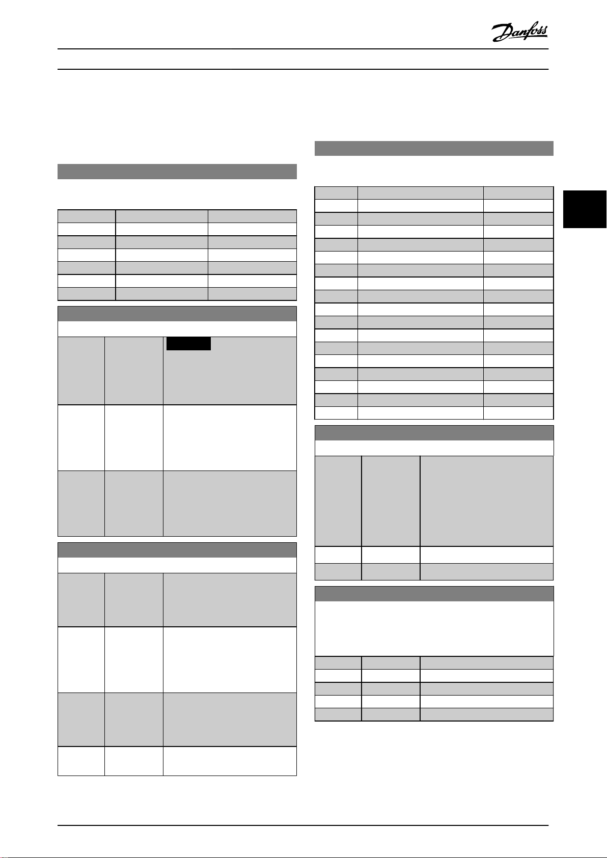
4.1 Parameters: 0-** Operation and Display
0-01 Language
Select the language to be used in the display.
Option: Function:
[0] * English
[1] Deutsch
[2] Francais
[3] Dansk
[4] Spanish
[5] Italiano
[28] Portuguese
0-06 GridType
Select the supply voltage, frequency, and type.
Option: Function:
[0] 200-240V/50Hz/IT-grid
[1] 200-240V/50Hz/Delta
[2] 200-240V/50Hz
[10] 380-440V/50Hz/IT-grid
[11] 380-440V/50Hz/Delta
[12] 380-440V/50Hz
[20] 440-480V/50Hz/IT-grid
[21] 440-480V/50Hz/Delta
[22] 440-480V/50Hz
[100] 200-240V/60Hz/IT-grid
[101] 200-240V/60Hz/Delta
[102] 200-240V/60Hz
[110] 380-440V/60Hz/IT-grid
[111] 380-440V/60Hz/Delta
[112] 380-440V/60Hz
[120] 440-480V/60Hz/IT-grid
[121] 440-480V/60Hz/Delta
[122] 440-480V/60Hz
4 4
MG07C402 Danfoss A/S © 02/2019 All rights reserved. 25
0-11 Programming Set-up
Select the set-up to be programmed during operation; either the
active set-up or the inactive set-up. The set-up number being
edited ashes in the LCP.
Option: Function:
[1] Set-up 1
[2] Set-up 2
[3] Set-up 3
[4] Set-up 4
[9] * Active Set-up
0-12 Link Setups
Option: Function:
The link ensures synchronizing of
the Not changeable during operation
parameter values enabling shift
from 1 set-up to another during
operation.
If the set-ups are not linked, a
change between them is not
possible while the motor is running.
Thus the set-up change does not
occur until the motor is coasted.
[0] Not linked Leave parameters unchanged in
both set-ups. These parameters
cannot be changed while the motor
is running.
[20] * Linked Copy Not changeable during
operation parameters from 1 set-up
to the other, so they are identical in
both set-ups.
0-14 Readout: Edit Set-ups / Channel
Range: Function:
0* [-2147483647
2147483647 ]
View the setting of
parameter 0-11 Programming Set-up.
Edit set-up for each communication
channel. A means active set-up; F
means factory; numbers indicate
set-up code. Communication
channels from right to left are LCP,
FC-bus, USB, and HPFB1-5.
0-16 Application Selection
Option: Function:
Select integrated application
functions. When an application is
selected, a set of related parameters
are set automatically.
[0] * None
[1] Simple Process
Close Loop
[2] Local/Remote
0-16 Application Selection
Option: Function:
[3] Speed Open
Loop
[4] Simple Speed
Close Loop
[5] Multi Speed
[6] OGD LA10
[7] OGD V210
[8] Hoist
0-20 Display Line 1.1 Small
Select a variable to be shown in line 1, left position.
Option: Function:
[0] None
[37] Display Text 1
[38] Display Text 2
[39] Display Text 3
[748] PCD Feed
Forward
[953] Probus
Warning Word
[1005] Readout
Transmit Error
Counter
[1006] Readout
Receive Error
Counter
[1230] Warning
Parameter
[1501] Running Hours
[1502] kWh Counter
[1600] Control Word
[1601] Reference
[Unit]
[1602] * Reference [%]
[1603] Status Word
[1605] Main Actual
Value [%]
[1609] Custom
Readout
[1610] Power [kW]
[1611] Power [hp]
[1612] Motor Voltage
[1613] Frequency
[1614] Motor current
[1615] Frequency [%]
[1616] Torque [Nm]
[1617] Speed [RPM]
[1618] Motor Thermal
[1620] Motor Angle
[1622] Torque [%]
[1630] DC Link
Voltage
Parameter Descriptions
44
26 Danfoss A/S © 02/2019 All rights reserved. MG07C402
VLT® Midi Drive FC 280
0-20 Display Line 1.1 Small
Select a variable to be shown in line 1, left position.
Option: Function:
[1633] Brake
Energy /2 min
[1634] Heatsink
Temp.
[1635] Inverter
Thermal
[1636] Inv. Nom.
Current
[1637] Inv. Max.
Current
[1638] SL Controller
State
[1639] Control Card
Temp.
[1650] External
Reference
[1652] Feedback[Unit]
[1653] Digi Pot
Reference
[1657] Feedback
[RPM]
[1660] Digital Input
[1661] Terminal 53
Setting
[1662] Analog input
53
[1663] Terminal 54
Setting
[1664] Analog input
54
[1665] Analog output
42 [mA]
[1666] Digital Output
[1667] Pulse input 29
[Hz]
[1668] Pulse input 33
[Hz]
[1669] Pulse output
27 [Hz]
[1671] Relay output
[1672] Counter A
[1673] Counter B
[1674] Prec. Stop
Counter
[1680] Fieldbus CTW
1
[1682] Fieldbus REF 1
[1684] Comm. Option
STW
[1685] FC Port CTW 1
[1686] FC Port REF 1
[1690] Alarm Word
0-20 Display Line 1.1 Small
Select a variable to be shown in line 1, left position.
Option: Function:
[1691] Alarm Word 2
[1692] Warning Word
[1693] Warning Word
2
[1694] Ext. Status
Word
[1695] Ext. Status
Word 2
[1697] Alarm Word 3
[1698] Warning Word
3
[1890] Process PID
Error
[1891] Process PID
Output
[1892] Process PID
Clamped
Output
[1893] Process PID
Gain Scaled
Output
[2117] Ext. 1
Reference
[Unit]
[2118] Ext. 1
Feedback
[Unit]
[2119] Ext. 1 Output
[%]
[3401] PCD 1 Write
For
Application
[3402] PCD 2 Write
For
Application
[3403] PCD 3 Write
For
Application
[3404] PCD 4 Write
For
Application
[3405] PCD 5 Write
For
Application
[3406] PCD 6 Write
For
Application
[3407] PCD 7 Write
For
Application
[3408] PCD 8 Write
For
Application
Parameter Descriptions Programming Guide
MG07C402 Danfoss A/S © 02/2019 All rights reserved. 27
4 4
0-20 Display Line 1.1 Small
Select a variable to be shown in line 1, left position.
Option: Function:
[3409] PCD 9 Write
For
Application
[3410] PCD 10 Write
For
Application
[3421] PCD 1 Read
For
Application
[3422] PCD 2 Read
For
Application
[3423] PCD 3 Read
For
Application
[3424] PCD 4 Read
For
Application
[3425] PCD 5 Read
For
Application
[3426] PCD 6 Read
For
Application
[3427] PCD 7 Read
For
Application
[3428] PCD 8 Read
For
Application
[3429] PCD 9 Read
For
Application
[3430] PCD 10 Read
For
Application
[3450] Actual Position
[3456] Track Error
0-21 Display Line 1.2 Small
Select a variable to be shown in line 1, middle position.
Option: Function:
[0] None
[37] Display Text 1
[38] Display Text 2
[39] Display Text 3
[748] PCD Feed
Forward
[953] Probus
Warning Word
0-21 Display Line 1.2 Small
Select a variable to be shown in line 1, middle position.
Option: Function:
[1005] Readout
Transmit Error
Counter
[1006] Readout
Receive Error
Counter
[1230] Warning
Parameter
[1501] Running Hours
[1502] kWh Counter
[1600] Control Word
[1601] Reference
[Unit]
[1602] Reference [%]
[1603] Status Word
[1605] Main Actual
Value [%]
[1609] Custom
Readout
[1610] Power [kW]
[1611] Power [hp]
[1612] Motor Voltage
[1613] Frequency
[1614] * Motor current
[1615] Frequency [%]
[1616] Torque [Nm]
[1617] Speed [RPM]
[1618] Motor Thermal
[1620] Motor Angle
[1622] Torque [%]
[1630] DC Link
Voltage
[1633] Brake
Energy /2 min
[1634] Heatsink
Temp.
[1635] Inverter
Thermal
[1636] Inv. Nom.
Current
[1637] Inv. Max.
Current
[1638] SL Controller
State
[1639] Control Card
Temp.
[1650] External
Reference
[1652] Feedback[Unit]
[1653] Digi Pot
Reference
Parameter Descriptions
44
28 Danfoss A/S © 02/2019 All rights reserved. MG07C402
VLT® Midi Drive FC 280

0-21 Display Line 1.2 Small
Select a variable to be shown in line 1, middle position.
Option: Function:
[1657] Feedback
[RPM]
[1660] Digital Input
[1661] Terminal 53
Setting
[1662] Analog input
53
[1663] Terminal 54
Setting
[1664] Analog input
54
[1665] Analog output
42 [mA]
[1666] Digital Output
[1667] Pulse input 29
[Hz]
[1668] Pulse input 33
[Hz]
[1669] Pulse output
27 [Hz]
[1671] Relay output
[1672] Counter A
[1673] Counter B
[1674] Prec. Stop
Counter
[1680] Fieldbus CTW
1
[1682] Fieldbus REF 1
[1684] Comm. Option
STW
[1685] FC Port CTW 1
[1686] FC Port REF 1
[1690] Alarm Word
[1691] Alarm Word 2
[1692] Warning Word
[1693] Warning Word
2
[1694] Ext. Status
Word
[1695] Ext. Status
Word 2
[1697] Alarm Word 3
[1698] Warning Word
3
[1890] Process PID
Error
[1891] Process PID
Output
[1892] Process PID
Clamped
Output
0-21 Display Line 1.2 Small
Select a variable to be shown in line 1, middle position.
Option: Function:
[1893] Process PID
Gain Scaled
Output
[2117] Ext. 1
Reference
[Unit]
[2118] Ext. 1
Feedback
[Unit]
[2119] Ext. 1 Output
[%]
[3401] PCD 1 Write
For
Application
[3402] PCD 2 Write
For
Application
[3403] PCD 3 Write
For
Application
[3404] PCD 4 Write
For
Application
[3405] PCD 5 Write
For
Application
[3406] PCD 6 Write
For
Application
[3407] PCD 7 Write
For
Application
[3408] PCD 8 Write
For
Application
[3409] PCD 9 Write
For
Application
[3410] PCD 10 Write
For
Application
[3421] PCD 1 Read
For
Application
[3422] PCD 2 Read
For
Application
[3423] PCD 3 Read
For
Application
[3424] PCD 4 Read
For
Application
Parameter Descriptions Programming Guide
MG07C402 Danfoss A/S © 02/2019 All rights reserved. 29
4 4

0-21 Display Line 1.2 Small
Select a variable to be shown in line 1, middle position.
Option: Function:
[3425] PCD 5 Read
For
Application
[3426] PCD 6 Read
For
Application
[3427] PCD 7 Read
For
Application
[3428] PCD 8 Read
For
Application
[3429] PCD 9 Read
For
Application
[3430] PCD 10 Read
For
Application
[3450] Actual Position
[3456] Track Error
0-22 Display Line 1.3 Small
Select a variable to be shown in line 1, right position.
Option: Function:
[0] None
[37] Display Text 1
[38] Display Text 2
[39] Display Text 3
[748] PCD Feed
Forward
[953] Probus
Warning Word
[1005] Readout
Transmit Error
Counter
[1006] Readout
Receive Error
Counter
[1230] Warning
Parameter
[1501] Running Hours
[1502] kWh Counter
[1600] Control Word
[1601] Reference
[Unit]
[1602] Reference [%]
[1603] Status Word
[1605] Main Actual
Value [%]
[1609] Custom
Readout
[1610] * Power [kW ]
0-22 Display Line 1.3 Small
Select a variable to be shown in line 1, right position.
Option: Function:
[1611] Power [hp]
[1612] Motor Voltage
[1613] Frequency
[1614] Motor current
[1615] Frequency [%]
[1616] Torque [Nm]
[1617] Speed [RPM]
[1618] Motor Thermal
[1620] Motor Angle
[1622] Torque [%]
[1630] DC Link
Voltage
[1633] Brake
Energy /2 min
[1634] Heatsink
Temp.
[1635] Inverter
Thermal
[1636] Inv. Nom.
Current
[1637] Inv. Max.
Current
[1638] SL Controller
State
[1639] Control Card
Temp.
[1650] External
Reference
[1652] Feedback[Unit]
[1653] Digi Pot
Reference
[1657] Feedback
[RPM]
[1660] Digital Input
[1661] Terminal 53
Setting
[1662] Analog input
53
[1663] Terminal 54
Setting
[1664] Analog input
54
[1665] Analog output
42 [mA]
[1666] Digital Output
[1667] Pulse input 29
[Hz]
[1668] Pulse input 33
[Hz]
[1669] Pulse output
27 [Hz]
[1671] Relay output
Parameter Descriptions
44
30 Danfoss A/S © 02/2019 All rights reserved. MG07C402
VLT® Midi Drive FC 280

0-22 Display Line 1.3 Small
Select a variable to be shown in line 1, right position.
Option: Function:
[1672] Counter A
[1673] Counter B
[1674] Prec. Stop
Counter
[1680] Fieldbus CTW
1
[1682] Fieldbus REF 1
[1684] Comm. Option
STW
[1685] FC Port CTW 1
[1686] FC Port REF 1
[1690] Alarm Word
[1691] Alarm Word 2
[1692] Warning Word
[1693] Warning Word
2
[1694] Ext. Status
Word
[1695] Ext. Status
Word 2
[1697] Alarm Word 3
[1698] Warning Word
3
[1890] Process PID
Error
[1891] Process PID
Output
[1892] Process PID
Clamped
Output
[1893] Process PID
Gain Scaled
Output
[2117] Ext. 1
Reference
[Unit]
[2118] Ext. 1
Feedback
[Unit]
[2119] Ext. 1 Output
[%]
[3401] PCD 1 Write
For
Application
[3402] PCD 2 Write
For
Application
[3403] PCD 3 Write
For
Application
0-22 Display Line 1.3 Small
Select a variable to be shown in line 1, right position.
Option: Function:
[3404] PCD 4 Write
For
Application
[3405] PCD 5 Write
For
Application
[3406] PCD 6 Write
For
Application
[3407] PCD 7 Write
For
Application
[3408] PCD 8 Write
For
Application
[3409] PCD 9 Write
For
Application
[3410] PCD 10 Write
For
Application
[3421] PCD 1 Read
For
Application
[3422] PCD 2 Read
For
Application
[3423] PCD 3 Read
For
Application
[3424] PCD 4 Read
For
Application
[3425] PCD 5 Read
For
Application
[3426] PCD 6 Read
For
Application
[3427] PCD 7 Read
For
Application
[3428] PCD 8 Read
For
Application
[3429] PCD 9 Read
For
Application
[3430] PCD 10 Read
For
Application
[3450] Actual Position
[3456] Track Error
Parameter Descriptions Programming Guide
MG07C402 Danfoss A/S © 02/2019 All rights reserved. 31
4 4

0-23 Display Line 2 Large
Select a variable to be shown in line 2.
Option: Function:
[0] None
[37] Display Text 1
[38] Display Text 2
[39] Display Text 3
[748] PCD Feed
Forward
[953] Probus
Warning Word
[1005] Readout
Transmit Error
Counter
[1006] Readout
Receive Error
Counter
[1230] Warning
Parameter
[1501] Running Hours
[1502] kWh Counter
[1600] Control Word
[1601] Reference
[Unit]
[1602] Reference [%]
[1603] Status Word
[1605] Main Actual
Value [%]
[1609] Custom
Readout
[1610] Power [kW]
[1611] Power [hp]
[1612] Motor Voltage
[1613] * Frequency
[1614] Motor current
[1615] Frequency [%]
[1616] Torque [Nm]
[1617] Speed [RPM]
[1618] Motor Thermal
[1620] Motor Angle
[1622] Torque [%]
[1630] DC Link
Voltage
[1633] Brake
Energy /2 min
[1634] Heatsink
Temp.
[1635] Inverter
Thermal
[1636] Inv. Nom.
Current
[1637] Inv. Max.
Current
[1638] SL Controller
State
0-23 Display Line 2 Large
Select a variable to be shown in line 2.
Option: Function:
[1639] Control Card
Temp.
[1650] External
Reference
[1652] Feedback[Unit]
[1653] Digi Pot
Reference
[1657] Feedback
[RPM]
[1660] Digital Input
[1661] Terminal 53
Setting
[1662] Analog input
53
[1663] Terminal 54
Setting
[1664] Analog input
54
[1665] Analog output
42 [mA]
[1666] Digital Output
[1667] Pulse input 29
[Hz]
[1668] Pulse input 33
[Hz]
[1669] Pulse output
27 [Hz]
[1671] Relay output
[1672] Counter A
[1673] Counter B
[1674] Prec. Stop
Counter
[1680] Fieldbus CTW
1
[1682] Fieldbus REF 1
[1684] Comm. Option
STW
[1685] FC Port CTW 1
[1686] FC Port REF 1
[1690] Alarm Word
[1691] Alarm Word 2
[1692] Warning Word
[1693] Warning Word
2
[1694] Ext. Status
Word
[1695] Ext. Status
Word 2
[1697] Alarm Word 3
[1698] Warning Word
3
Parameter Descriptions
44
32 Danfoss A/S © 02/2019 All rights reserved. MG07C402
VLT® Midi Drive FC 280

0-23 Display Line 2 Large
Select a variable to be shown in line 2.
Option: Function:
[1890] Process PID
Error
[1891] Process PID
Output
[1892] Process PID
Clamped
Output
[1893] Process PID
Gain Scaled
Output
[2117] Ext. 1
Reference
[Unit]
[2118] Ext. 1
Feedback
[Unit]
[2119] Ext. 1 Output
[%]
[3401] PCD 1 Write
For
Application
[3402] PCD 2 Write
For
Application
[3403] PCD 3 Write
For
Application
[3404] PCD 4 Write
For
Application
[3405] PCD 5 Write
For
Application
[3406] PCD 6 Write
For
Application
[3407] PCD 7 Write
For
Application
[3408] PCD 8 Write
For
Application
[3409] PCD 9 Write
For
Application
[3410] PCD 10 Write
For
Application
[3421] PCD 1 Read
For
Application
0-23 Display Line 2 Large
Select a variable to be shown in line 2.
Option: Function:
[3422] PCD 2 Read
For
Application
[3423] PCD 3 Read
For
Application
[3424] PCD 4 Read
For
Application
[3425] PCD 5 Read
For
Application
[3426] PCD 6 Read
For
Application
[3427] PCD 7 Read
For
Application
[3428] PCD 8 Read
For
Application
[3429] PCD 9 Read
For
Application
[3430] PCD 10 Read
For
Application
[3450] Actual Position
[3456] Track Error
0-24 Display Line 3 Large
Select a variable to be shown in line 3.
Option: Function:
[0] None
[37] Display Text 1
[38] Display Text 2
[39] Display Text 3
[748] PCD Feed
Forward
[953] Probus
Warning Word
[1005] Readout
Transmit Error
Counter
[1006] Readout
Receive Error
Counter
[1230] Warning
Parameter
[1501] Running Hours
[1502] * kWh Counter
[1600] Control Word
Parameter Descriptions Programming Guide
MG07C402 Danfoss A/S © 02/2019 All rights reserved. 33
4 4

0-24 Display Line 3 Large
Select a variable to be shown in line 3.
Option: Function:
[1601] Reference
[Unit]
[1602] Reference [%]
[1603] Status Word
[1605] Main Actual
Value [%]
[1609] Custom
Readout
[1610] Power [kW]
[1611] Power [hp]
[1612] Motor Voltage
[1613] Frequency
[1614] Motor current
[1615] Frequency [%]
[1616] Torque [Nm]
[1617] Speed [RPM]
[1618] Motor Thermal
[1620] Motor Angle
[1622] Torque [%]
[1630] DC Link
Voltage
[1633] Brake
Energy /2 min
[1634] Heatsink
Temp.
[1635] Inverter
Thermal
[1636] Inv. Nom.
Current
[1637] Inv. Max.
Current
[1638] SL Controller
State
[1639] Control Card
Temp.
[1650] External
Reference
[1652] Feedback[Unit]
[1653] Digi Pot
Reference
[1657] Feedback
[RPM]
[1660] Digital Input
[1661] Terminal 53
Setting
[1662] Analog input
53
[1663] Terminal 54
Setting
[1664] Analog input
54
0-24 Display Line 3 Large
Select a variable to be shown in line 3.
Option: Function:
[1665] Analog output
42 [mA]
[1666] Digital Output
[1667] Pulse input 29
[Hz]
[1668] Pulse input 33
[Hz]
[1669] Pulse output
27 [Hz]
[1671] Relay output
[1672] Counter A
[1673] Counter B
[1674] Prec. Stop
Counter
[1680] Fieldbus CTW
1
[1682] Fieldbus REF 1
[1684] Comm. Option
STW
[1685] FC Port CTW 1
[1686] FC Port REF 1
[1690] Alarm Word
[1691] Alarm Word 2
[1692] Warning Word
[1693] Warning Word
2
[1694] Ext. Status
Word
[1695] Ext. Status
Word 2
[1697] Alarm Word 3
[1698] Warning Word
3
[1890] Process PID
Error
[1891] Process PID
Output
[1892] Process PID
Clamped
Output
[1893] Process PID
Gain Scaled
Output
[2117] Ext. 1
Reference
[Unit]
[2118] Ext. 1
Feedback
[Unit]
[2119] Ext. 1 Output
[%]
Parameter Descriptions
44
34 Danfoss A/S © 02/2019 All rights reserved. MG07C402
VLT® Midi Drive FC 280

0-24 Display Line 3 Large
Select a variable to be shown in line 3.
Option: Function:
[3401] PCD 1 Write
For
Application
[3402] PCD 2 Write
For
Application
[3403] PCD 3 Write
For
Application
[3404] PCD 4 Write
For
Application
[3405] PCD 5 Write
For
Application
[3406] PCD 6 Write
For
Application
[3407] PCD 7 Write
For
Application
[3408] PCD 8 Write
For
Application
[3409] PCD 9 Write
For
Application
[3410] PCD 10 Write
For
Application
[3421] PCD 1 Read
For
Application
[3422] PCD 2 Read
For
Application
[3423] PCD 3 Read
For
Application
[3424] PCD 4 Read
For
Application
[3425] PCD 5 Read
For
Application
[3426] PCD 6 Read
For
Application
[3427] PCD 7 Read
For
Application
0-24 Display Line 3 Large
Select a variable to be shown in line 3.
Option: Function:
[3428] PCD 8 Read
For
Application
[3429] PCD 9 Read
For
Application
[3430] PCD 10 Read
For
Application
[3450] Actual Position
[3456] Track Error
0-30 Custom Readout Unit
Set a value to be shown in the LCP. The value has a linear,
squared, or cubed relation to speed. This relation depends on
the unit selected.
Option: Function:
[0] None
[1] * %
[5] PPM
[10] 1/min
[11] RPM
[12] Pulse/s
[20] l/s
[21] l/min
[22] l/h
[23] m³/s
[24] m³/min
[25] m³/h
[30] kg/s
[31] kg/min
[32] kg/h
[33] t/min
[34] t/h
[40] m/s
[41] m/min
[45] m
[60] °C
[70] mbar
[71] bar
[72] Pa
[73] kPa
[74] m WG
[80] kW
[120] GPM
[121] gal/s
[122] gal/min
[123] gal/h
[124] CFM
[127] ft³/h
[140] ft/s
Parameter Descriptions Programming Guide
MG07C402 Danfoss A/S © 02/2019 All rights reserved. 35
4 4

0-30 Custom Readout Unit
Set a value to be shown in the LCP. The value has a linear,
squared, or cubed relation to speed. This relation depends on
the unit selected.
Option: Function:
[141] ft/min
[160] °F
[170] psi
[171] lb/in2
[172] in WG
[173] ft WG
[180] HP
0-31 Custom Readout Min Value
Range: Function:
0 CustomReadoutUni
t*
[ 0 -
999999.99
CustomRea-
doutUnit]
This parameter sets the minimum
value of the custom readout (occurs
at 0 speed). It is only possible to
select a value dierent from 0
when selecting a linear unit in
parameter 0-30 Custom Readout
Unit. For quadratic and cubic units,
the minimum value is 0.
0-32 Custom Readout Max Value
Range: Function:
100
CustomReadoutUni
t*
[ 0.0 -
999999.99
CustomRea-
doutUnit]
This parameter sets the maximum
value to be shown when the motor
speed has reached the value set in
parameter 4-14 Motor Speed High
Limit [Hz].
0-37 Display Text 1
Range: Function:
[0 - 0 ] Free text, for example used for the
device tag of eldbus application.
0-38 Display Text 2
Range: Function:
[0 - 0 ] Free text, for example used for the
location tag of eldbus application.
0-39 Display Text 3
Range: Function:
[0 - 0 ] Free text, for example used for the
help tag of eldbus application.
0-40 [Hand on] Key on LCP
Option: Function:
[0] Disabled Avoid accidental start of the
frequency converter in hand-on
mode.
[1] * Enabled [Hand On] is enabled.
0-42 [Auto on] Key on LCP
Option: Function:
[0] Disabled Avoid accidental start of the
freqeuncy converter from LCP.
[1] * Enabled [Auto On] is enabled.
0-44 [O/Reset] Key on LCP
Option: Function:
[0] Disabled Select [0] Disabled to avoid
accidental stop or reset of the
frequency converter from LCP.
Setting can be locked by
parameter 0-60 Main Menu
Password.
[1] * Enabled
[7] Enable Reset
Only
0-50 LCP Copy
Option: Function:
[0] * No copy No function.
[1] All to LCP Copy all parameters in all set-ups
from the frequency converter
memory to the LCP. For service
purposes, copy all parameters to
the LCP after commissioning.
[2] All from LCP Copy all parameters in all set-ups
from the LCP memory to the
frequency converter memory.
[3] Size indep.
from LCP
Copy only the parameters that are
independent of the motor size. This
selection can be used to program
several frequency converters with
the same function without
disturbing motor data that is
already set.
0-51 Set-up Copy
Use this parameter to copy parameters between set-ups.
Option: Function:
[0] * No copy
[1] Copy from
setup 1
[2] Copy from
setup 2
[3] Copy from
setup 3
[4] Copy from
setup 4
[9] Copy from
Factory setup
Parameter Descriptions
VLT® Midi Drive FC 280
44
36 Danfoss A/S © 02/2019 All rights reserved. MG07C402

0-60 Main Menu Password
Range: Function:
0* [0 - 999 ] Dene the password for accessing
the Main Menu via the [Main Menu]
key. Setting the value to 0 disables
the password function.
1-00 Conguration Mode
Option: Function:
Select the application control
principle to be used when a remote
reference (that is analog input or
eldbus) is active.
[0] * Open Loop Enable speed control (without
feedback signal from motor) with
automatic slip compensation for
almost constant speed at varying
loads. Compensations are active,
but can be disabled in parameter
group 1-0* Load and Motor.
[1] Speed closed
loop
Enable speed closed-loop control
with feedback. For increased speed
accuracy, provide a feedback signal
and set the speed PID control. The
speed control parameters are set in
parameter group 7-0* Speed PID
Control.
[2] Torque closed
loop
Enable torque closed-loop control
with speed feedback. Only possible
when option [1] VVC+ is selected in
parameter 1-01 Motor Control
Principle.
[3] Process Closed
Loop
Enable the use of process control in
the frequency converter. The
process control parameters are set
in parameter groups 7-2* Process
Ctrl. Feedback and 7-3* Process PID
Ctrl.
[4] Torque open
loop
Enable the use of torque open loop
in the frequency converter.
[7] Extended PID
Speed OL
Enable the use of extended PID
speed OL in the frequency
converter.
1-01 Motor Control Principle
Option: Function:
[0] U/f
NOTICE
When running U/f, control slip
and load compensations are
not included.
1-01 Motor Control Principle
Option: Function:
Used for parallel-connected motors
and/or special motor applications.
Set the U/f settings in
parameter 1-55 U/f Characteristic - U
and parameter 1-56 U/f Characteristic - F.
[1] * VVC+
NOTICE
When parameter 1-10 Motor
Construction is set to PM-
enabled options, only VVC
+
option is available.
Normal running mode, including
slip and load compensations.
1-03 Torque Characteristics
Option: Function:
Select the torque characteristic
required. VT and AEO are both
energy-saving operations.
[0] * Constant
torque
Motor shaft output provides
constant torque under variable
speed control.
[1] Variable
Torque
Motor shaft output provides
variable torque under variable
speed control. Set the variable
torque level in parameter 14-40 VT
Level.
[2] Auto Energy
Optim. CT
Automatically optimizes energy
consumption by minimizing
magnetization and frequency via
parameter 14-41 AEO Minimum
Magnetisation.
1-06 Clockwise Direction
Option: Function:
NOTICE
This parameter cannot be
adjusted while the motor is
running.
This parameter denes the term
clockwise corresponding to the LCP
direction arrow. Used for easy
change of direction of shaft
rotation without swapping motor
wires.
[0] * Normal The motor shaft turns in clockwise
direction when frequency converter
is connected U⇒U; V⇒V; and W⇒W
to motor.
Parameter Descriptions Programming Guide
4.2 Parameters: 1-** Load and Motor
4 4
MG07C402 Danfoss A/S © 02/2019 All rights reserved. 37

1-06 Clockwise Direction
Option: Function:
[1] Inverse The motor shaft turns in counter-
clockwise direction when frequency
converter is connected U⇒U; V⇒V;
and W⇒W to motor.
1-14 Damping Gain
Range: Function:
120 %* [ 0 - 250 %] The damping gain stabilizes the PM
machine. The value of damping
gain controls the dynamic
performance of the PM machine.
High damping gain gives high
dynamic performance, and low
damping gain gives low dynamic
performance. The dynamic
performance is related to the
machine data and load type. If the
damping gain is too high or low,
the control becomes unstable.
1-15 Low Speed Filter Time Const.
Range: Function:
Size
related*
[ 0.01 - 20 s] This time constant is used below
10% rated speed. Obtain quick
control through a short damping
time constant. However, if this value
is too short, the control becomes
unstable.
1-16 High Speed Filter Time Const.
Range: Function:
Size
related*
[ 0.01 - 20 s] This time constant is used above
10% rated speed. Obtain quick
control through a short damping
time constant. However, if this value
is too short, the control becomes
unstable.
1-17 Voltage lter time const.
Range: Function:
Size
related*
[ 0.001 - 1 s] Reduce the inuence of high
frequency ripple and system
resonance in the calculation of
supply voltage. Without this lter,
the ripples in the currents can
distort the calculated voltage and
aect the stability of the system.
1-20 Motor Power
Option: Function:
[2] 0.12 kW - 0.16
hp
[3] 0.18 kW - 0.25
hp
[4] 0.25 kW - 0.33
hp
[5] 0.37 kW - 0.5
hp
[6] 0.55 kW - 0.75
hp
[7] 0.75 kW - 1 hp
[8] 1.1 kW - 1.5
hp
[9] 1.5 kW - 2 hp
[10] 2.2 kW - 3 hp
[11] 3 kW - 4 hp
[12] 3.7 kW - 5 hp
[13] 4 kW - 5.4 hp
[14] 5.5 kW - 7.5
hp
[15] 7.5 kW - 10 hp
[16] 11 kW - 15 hp
[17] 15 kW - 20 hp
[18] 18.5 kW - 25
hp
[19] 22 kW - 30 hp
[20] 30 kW - 40 hp
1-22 Motor Voltage
Range: Function:
Size
related*
[50 - 1000 V] Enter the nominal motor voltage
according to the motor nameplate
data. The default value corresponds
Parameter Descriptions
VLT® Midi Drive FC 280
1-08 Motor Control Bandwidth
44
Option: Function:
[0] High Suitable for high dynamic response.
[1] * Medium Suitable for smooth steady-state operation.
[2] Low Suitable for smooth steady-state operation with
lowest dynamic response.
[3] Adaptive 1 Optimized for smooth steady-state operation,
with extra active damping.
[4] Adaptive 2 Focus on low-inductance PM motors. This
option is an alternative to [3] Adaptive 1.
4.2.1 1-10 Motor Construction
1-10 Motor Construction
Option: Function:
[0] * Asynchron For asynchronous motors.
[1] PM, non
[3] PM, salient
salient SPM
IPM
For permanent magnet (PM) motors with
surface-mounted (non-salient) magnets.
Refer to parameter 1-14 Damping Gain to
parameter 1-17 Voltage lter time const. for
details about optimizing the motor
operation.
For permanent magnet (PM) motors with
interior (salient) magnets.
38 Danfoss A/S © 02/2019 All rights reserved. MG07C402

1-22 Motor Voltage
Range: Function:
to the nominal rated output of the
unit.
1-23 Motor Frequency
Range: Function:
NOTICE
This parameter cannot be
adjusted while the motor is
running.
Size
related*
[ 20 - 500 Hz] Select the motor frequency value
from the motor nameplate. For 87
Hz operation with 230/440 V
motors, set the value according to
the nameplate data for 230 V/50
Hz. Adapt parameter 4-14 Motor
Speed High Limit [Hz] and
parameter 3-03 Maximum Reference
to the 87 Hz application.
1-24 Motor Current
Range: Function:
Size
related*
[ 0.01 -
1000.00 A]
Enter the nominal motor current
value from the motor nameplate
data. This data is used for
calculating motor torque, motor
thermal protection, and so on.
1-25 Motor Nominal Speed
Range: Function:
Size
related*
[50 - 60000
RPM]
Enter the nominal motor speed
value from the motor nameplate
data. This data is used for
calculating automatic motor
compensations.
1-26 Motor Cont. Rated Torque
Range: Function:
Size
related*
[0.1 -
10000.0 Nm]
Enter the value from the motor
nameplate data. The default value
corresponds to the nominal rated
output. This parameter is available
when parameter 1-10 Motor
Construction is set to [1] PM, non
salient SPM or [3] PM, salient IPM,
that is, the parameter is valid for
PM, non-salient SPM and PM,
salient IPM motors only.
1-29 Automatic Motor Adaption (AMA)
Option: Function:
NOTICE
This parameter cannot be
adjusted while the motor is
running.
NOTICE
Terminal 27 digital input
(parameter 5-12 Terminal 27
Digital Input) has coast inverse
as the default setting. This
setting means that AMA
cannot be performed if
terminal 27 is switched o.
The AMA function optimizes
dynamic motor performance by
automatically optimizing the
advanced motor parameters.
[0] * O No function.
[1] Enable
Complete
AMA
Depending on the option selected
in parameter 1-10 Motor
Construction, the AMA is performed
on dierent parameters.
•
If [0] Asynchron is selected,
the AMA is performed on:
- Parameter 1-30 St
ator Resistance
(Rs).
- Parameter 1-31 R
otor Resistance
(Rr).
- Parameter 1-33 St
ator Leakage
Reactance (X1).
- Parameter 1-35 M
ain Reactance
(Xh).
•
If [1] PM, non-salient SPM
is selected, the AMA is
performed on:
- Parameter 1-30 St
ator Resistance
(Rs).
- Parameter 1-37 d-
axis Inductance
(Ld).
•
If [3] PM, salient IPM is
selected, the AMA is
performed on:
Parameter Descriptions Programming Guide
4 4
MG07C402 Danfoss A/S © 02/2019 All rights reserved. 39

1-29 Automatic Motor Adaption (AMA)
Option: Function:
- Parameter 1-30 St
ator Resistance
(Rs).
- Parameter 1-37 d-
axis Inductance
(Ld).
- Parameter 1-38 q-
axis Inductance
(Lq).
- Parameter 1-44 d-
axis Inductance
Sat. (LdSat).
- Parameter 1-45 q-
axis Inductance
Sat. (LqSat).
[2] Enable
Reduced AMA
Perform a reduced AMA of the
stator resistance R
s
(parameter 1-30 Stator Resistance
(Rs)) in the system only. If an LC
lter is used between the frequency
converter and the motor, select this
option. (This option is only for
asynchronous motors.)
1-30 Stator Resistance (Rs)
Range: Function:
Size
related*
[ 0.0 -
9999.000
Ohm]
NOTICE
This parameter cannot be
adjusted while the motor is
running.
Set the stator resistance value.
Enter the value from a motor
datasheet or perform an AMA on a
cold motor.
1-31 Rotor Resistance (Rr)
Range: Function:
Size
related*
[ 0 -
9999.000
Ohm]
NOTICE
This parameter cannot be
adjusted while the motor is
running.
Enter the rotor resistance value.
Obtain the value from a motor
datasheet or by performing an AMA
on a cold motor. The default setting
is calculated by the frequency
converter from the motor
nameplate data.
1-33 Stator Leakage Reactance (X1)
Range: Function:
Size
related*
[ 0.0 -
9999.000
Ohm]
NOTICE
This parameter cannot be
adjusted while the motor is
running.
Set the stator leakage reactance
value. Obtain the value from a
motor datasheet or perform an
AMA on a cold motor. The default
setting is calculated by the
frequency converter from the motor
nameplate data.
1-35 Main Reactance (Xh)
Range: Function:
Size
related*
[ 0.0 -
9999.00 Ohm]
NOTICE
This parameter cannot be
adjusted while the motor is
running.
Set the main reactance of the
motor using 1 of these methods:
•
Run an AMA on a cold
motor. The frequency
Parameter Descriptions
VLT® Midi Drive FC 280
44
When parameter 1-10 Motor Construction is set to options
that enable permanent motor mode, the only option
available is [1] Enable Complete AMA.
Activate the AMA function by pressing [Hand On] after
selecting [1] Enable Complete AMA or [2] Enable Reduced
AMA. After a normal sequence, the display reads: Press [OK]
to nish AMA. After pressing [OK], the frequency converter
is ready for operation.
NOTICE
For the best adaptation of the frequency
•
converter, run AMA on a cold motor.
AMA cannot be performed while the motor is
•
running.
NOTICE
Avoid generating external torque during AMA.
If an LC lter is used, set the frequency converter to run in
U/f control mode (recommended), or perform reduced
AMA in VVC+ mode. If an LC
complete AMA.
40 Danfoss A/S © 02/2019 All rights reserved. MG07C402
lter is not used, perform

1-35 Main Reactance (Xh)
Range: Function:
converter measures the
value from the motor.
•
Enter the Xh value
manually. Obtain the value
from the motor supplier.
•
Use the Xh default setting.
The frequency converter
establishes the setting
based on the motor
nameplate data.
1-37 d-axis Inductance (Ld)
Range: Function:
Size
related*
[ 0 - 65535
mH]
NOTICE
This parameter cannot be
adjusted while the motor is
running.
Enter the value of the d-axis
inductance. Obtain the value from
the permanent magnet motor
datasheet or perform an AMA on a
cold motor.
1-38 q-axis Inductance (Lq)
Range: Function:
Size
related*
[ 0.000 -
65535 mH]
NOTICE
This parameter cannot be
adjusted while the motor is
running.
Set the value of the q-axis
inductance. Find the value in the
motor datasheet or perform an
AMA on a cold motor.
1-39 Motor Poles
Range: Function:
Size
related*
[2 - 100 ]
NOTICE
This parameter cannot be
adjusted while the motor is
running.
Enter the number of motor poles.
The motor pole value is always an
even number, because it refers to
the total pole numbers, not pairs of
poles.
1-40 Back EMF at 1000 RPM
Range: Function:
Size
related*
[ 1 - 9000 V] Set the nominal back EMF for the
motor when running at 1000 RPM.
Back EMF is the voltage generated
by a PM motor when no frequency
converter is connected and the
shaft is turned externally. Back EMF
is normally specied for nominal
motor speed or for 1000 RPM
measured between 2 lines. If the
value is not available for a motor
speed of 1000 RPM, calculate the
correct value as follows: If back EMF
is, for example, 320 V at 1800 RPM,
it can be calculated at 1000 RPM:
Example
Back EMF 320 V at 1800 RPM. Back
EMF = (Voltage/RPM)*1000 =
(320/1800)*1000 = 178.
This parameter is only active when
parameter 1-10 Motor Construction is
set to options that enable PM
(permanent magnet) motors.
NOTICE
When using PM motors, it is
recommended to use brake
resistors.
1-42 Motor Cable Length
Range: Function:
50 m* [0 - 100 m] Set the motor cable length in
meters.
1-43 Motor Cable Length Feet
Range: Function:
164 ft* [0 - 328 ft] Set the motor cable length. The
length unit is foot.
1-44 d-axis Inductance Sat. (LdSat)
Range: Function:
Size related [ 0 - 65535
mH]
This parameter is active only when
parameter 1-10 Motor Construction is
set to [3] PM, salient IPM.
This parameter corresponds to the
saturation inductance of d-axis. The
default value is the value set in
parameter 1-37 d-axis Inductance
(Ld). In most cases, do not change
the default value. If the motor
supplier provides the saturation
curve, enter the d-axis inductance
value, which is under 100% of the
Parameter Descriptions Programming Guide
4 4
MG07C402 Danfoss A/S © 02/2019 All rights reserved. 41

1-44 d-axis Inductance Sat. (LdSat)
Range: Function:
nominal current or perform an AMA
on a cold motor.
1-45 q-axis Inductance Sat. (LqSat)
Range: Function:
Size
related*
[ 0 - 65535
mH]
This parameter is active only when
parameter 1-10 Motor Construction is
set to [3] PM, salient IPM.
This parameter corresponds to the
q-axis saturation inductance. The
default value is the value set in
parameter 1-38 q-axis Inductance
(Lq). In most cases, do not change
the default value. If the motor
supplier provides the saturation
curve, enter the q-axis inductance
value, which is under 100% of the
nominal current or perform an AMA
on a cold motor.
1-46 Position Detection Gain
Range: Function:
100 %* [ 20 - 200 %] Adjust the amplitude of the test
pulse during position detection at
start. Adjust this parameter to
improve the position measurement.
1-48 Current at Min Inductance for d-axis
Range: Function:
100 % [ 20 - 200 %] Use this parameter to set the
inductance saturation point.
1-49 Current at Min Inductance for q-axis
Range: Function:
100 % [ 20 - 200 %] This parameter species the
saturation curve of the qinductance values. From 20–100%
of this parameter, the inductance is
linearly approximated due to
parameter 1-38 q-axis Inductance
(Lq) and parameter 1-45 q-axis
Inductance Sat. (LqSat). These
parameters are related to the motor
nameplate load compensations, the
application load type, and the
electronic brake function for quick
stop/hold of the motor.
1-50 Motor Magnetisation at Zero Speed
Range: Function:
100 %* [0 - 300 %] Use this parameter along with
parameter 1-52 Min Speed Normal
Magnetising [Hz] to obtain a
1-50 Motor Magnetisation at Zero Speed
Range: Function:
dierent thermal load on the motor
when running at low speed.
Enter a value that is a percentage
of the rated magnetizing current. If
the setting is too low, the torque
on the motor shaft may be
reduced.
Magn. current
130BB780.10
Hz
Par.1-50
90%
Par.1-52
Illustration 4.1 Motor Magneti-
zation
1-52 Min Speed Normal Magnetising [Hz]
Range: Function:
1 Hz* [ 0.1 - 10.0
Hz]
Set the required frequency for
normal magnetizing current. Use
this parameter along with
parameter 1-50 Motor Magnetisation
at Zero Speed, also see
Illustration 4.1.
1-55 U/f Characteristic - U
Range: Function:
Size
related*
[0 - 1000 V] Enter voltage at each frequency
point to manually form a U/f
characteristic matching motor.
Frequency points are dened in
parameter 1-56 U/f Characteristic - F.
1-56 U/f Characteristic - F
Range: Function:
Size
related*
[ 0 - 500.0
Hz]
Enter frequency points to form a
U/f characteristic matching motor.
Voltage at each point is dened in
parameter 1-55 U/f Characteristic - U.
Make a U/f characteristic based on
6 denable voltages and
frequencies, see Illustration 4.2.
Parameter Descriptions
VLT® Midi Drive FC 280
44
42 Danfoss A/S © 02/2019 All rights reserved. MG07C402

1-56 U/f Characteristic - F
Range: Function:
Motor Voltage
Par 1-55 [x]
Output Frequency
Par 1-56 [x]
1-55[5]
1-55[4]
1-55[3]
1-55[2]
1-55[1]
1-55[0]
1-56
[0]
1-56
[1]
1-56
[2]
1-56
[3]
1-56
[4]
1-56
[5]
130BA166.10
Illustration 4.2 Example of U/f
Characteristic
1-60 Low Speed Load Compensation
Range: Function:
100 %* [0 - 300 %] Enter the low-speed voltage
compensation value in percent. This
parameter is used for optimizing
the low-speed load performance.
This parameter is only active if
parameter 1-10 Motor Construction =
[0] Asynchron.
1-61 High Speed Load Compensation
Range: Function:
100 %* [0 - 300 %] Enter the high-speed load voltage
compensation value in percent. This
parameter is used for optimizing
the high-speed load performance.
This parameter is only active if
parameter 1-10 Motor Construction =
[0] Asynchron.
1-62 Slip Compensation
Range: Function:
Size
related*
[ -400 -
400.0 %]
Enter the % value for slip compensation to compensate for tolerance
in the value of n
M,N
. Slip compensation is calculated automatically,
that is, based on the nominal motor
speed n
M,N
.
1-63 Slip Compensation Time Constant
Range: Function:
0.1 s* [0.05 - 5 s] Enter the slip compensation
reaction speed. A high value results
in slow reaction, and a low value
results in quick reaction. If lowfrequency resonance problems
occur, use a longer time setting.
1-64 Resonance Dampening
Range: Function:
100 %* [0 - 500 %] Enter the resonance dampening
value. Set parameter 1-64 Resonance
Dampening and
parameter 1-65 Resonance
Dampening Time Constant to help
eliminate high-frequency resonance
problems. To reduce resonance
oscillation, increase the value of
parameter 1-64 Resonance
Dampening.
1-65 Resonance Dampening Time Constant
Range: Function:
0.005 s* [ 0.001 - 0.05s]Set parameter 1-64 Resonance
Dampening and
parameter 1-65 Resonance
Dampening Time Constant to help
eliminate high-frequency resonance
problems. Enter the time constant
that provides the best dampening.
1-66 Min. Current at Low Speed
Range: Function:
50 %* [ 0 - 120 %] Enter the minimum motor current
at low speed. Increasing this current
improves motor torque at low
speed.
Parameter 1-66 Min. Current at Low
Speed is enabled only for PM motor.
1-70 Start Mode
Select the PM motor start-up mode. To initialize the VVC+ control
core for previously free-running PM motor. Active for PM motors
in VVC+ only if the motor is stopped (or running at low speed).
Option: Function:
[0] * Rotor
Detection
Estimates the electrical angle of the
rotor and uses this angle as a
starting point. This option is the
standard selection for industrial
applications. If ystart detects that
the motor runs at low speed or has
stopped, the frequency converter
detects the rotor position (the
angle) and starts the motor from
that position.
[1] Parking The parking function applies DC
current across the stator winding
and rotates the rotor to electrical 0
position. This option is typically for
pump and fan applications. If
ystart detects that the motor runs
at low speed or has stopped, the
frequency converter sends out a DC
Parameter Descriptions Programming Guide
4 4
MG07C402 Danfoss A/S © 02/2019 All rights reserved. 43

1-70 Start Mode
Select the PM motor start-up mode. To initialize the VVC+ control
core for previously free-running PM motor. Active for PM motors
in VVC+ only if the motor is stopped (or running at low speed).
Option: Function:
current to make the motor park at
an angle and then starts the motor
from that position.
[3] Rotor Last
Position
This option takes the advantage of
the last position of rotor at stop
and gives a quick start. It is only
used in the situation of controlled
stop, the frequency converter
records the last position of rotor at
stop and starts the motor directly
without rotor detection and angle
calculation. When in the situation of
non-controlled stop and power
cycle, the frequency converter
needs to detect the rotor position.
This option can be used for fast
restart application. Start may fail if
the rotor position has been
changed.
1-72 Start Function
Option: Function:
Select the start function during
start delay. This parameter is linked
to parameter 1-71 Start Delay.
[0] DC Hold/delay
time
Energize motor with a DC hold
current (parameter 2-00 DC Hold/
Motor Preheat Current) during the
start delay time.
[1] DC-Brake/
delay time
Energize motor with a DC hold
current (parameter 2-01 DC Brake
Current) during the start delay time.
[2] * Coast/delay
time
Motor coasted during the start
delay time (inverter o).
[3] Start speed
cw
Only possible with VVC+. Regardless
of the value applied by the
reference signal, the output speed
applies the setting of the start
speed in parameter 1-75 Star t Speed
[Hz] and the output current
corresponds to the setting of the
1-72 Start Function
Option: Function:
start current in parameter 1-76 Start
Current. This function is typically
used in hoisting applications
without counterweight and
especially in applications with a
cone-motor, where the start is
clockwise, followed by rotation in
the reference direction.
[4] Horizontal
operation
Only possible with VVC+.
For obtaining the function
described in parameter 1-75 Start
Speed [Hz] and parameter 1-76 Start
Current during the start delay time.
The motor rotates in the reference
direction. If the reference signal
equals 0, parameter 1-75 Star t Speed
[Hz] is ignored and the output
speed equals 0. The output current
corresponds to the setting of the
start current in parameter 1-76 Start
Current.
[5] VVC+
clockwise
The start current is calculated
automatically. This function uses
the start speed in the start delay
time only.
1-73 Flying Start
Option: Function:
NOTICE
This parameter cannot be
changed while the motor is
running.
NOTICE
To obtain the best ying start
performance, the advanced
motor data,
parameter 1-30 Stator
Resistance (Rs) to
parameter 1-35 Main Reactance
(Xh), must be correct.
Catch a motor which is spinning
freely due to a mains dropout.
[0] * Disabled No function.
[1] Enabled Enable the frequency converter to
catch and control a spinning motor.
When parameter 1-73 Flying Start is
enabled, parameter 1-71 Start Delay,
and parameter 1-72 Start Function
have no function.
Parameter Descriptions
VLT® Midi Drive FC 280
44
1-71 Start Delay
Range: Function:
0 s* [0.0 -
10.0 s]
This parameter enables a delay of the starting
time. The frequency converter begins with the
start function selected in parameter 1-72 Start
Function. Set the start delay time until
acceleration is to begin.
44 Danfoss A/S © 02/2019 All rights reserved. MG07C402

1-73 Flying Start
Option: Function:
[2] Enabled
Always
Enable ying start at every start
command.
[3] Enabled Ref.
Dir.
Enable the frequency converter to
catch and control a spinning motor.
The search is performed only in the
reference direction.
[4] Enab. Always
Ref. Dir.
Enable ying start at every start
command. The search is performed
only in the reference direction.
1-75 Start Speed [Hz]
Range: Function:
Size
related*
[ 0 - 500.0
Hz]
This parameter can be used for
hoist applications (cone rotor). Set a
motor start speed. After the start
signal, the output speed leaps to
the set value. Set the start function
in parameter 1-72 Start Function to
[3] Start speed cw, [4] Horizontal
operation, or [5] VVC+ clockwise, and
set a start delay time in
parameter 1-71 Start Delay.
1-76 Start Current
Range: Function:
Size
related*
[ 0 - 1000 A] Some motors, for example cone
rotor motors, need extra current/
starting speed to disengage the
rotor. To obtain this boost, set the
required current in this parameter.
Set parameter 1-72 Start Function to
[3] Start speed cw or [4] Horizontal
operation, and set a start delay time
in parameter 1-71 Start Delay.
1-78 Compressor Start Max Speed [Hz]
Range: Function:
0 Hz* [ 0 - 500 Hz] This parameter enables high
starting torque. The time from the
start signal is given until the speed
exceeds the speed set in this
parameter becomes a start zone. In
the start zone, the current limit and
motoric torque limit are set to the
maximum possible value for the
frequency converter/motor
combination. The time without
protection from the current limit
and torque limit must not exceed
the value set in
parameter 1-79 Compressor Start
Max Time to Trip. Otherwise, the
1-78 Compressor Start Max Speed [Hz]
Range: Function:
frequency converter trips with
alarm 18, Start Failed.
1-79 Compressor Start Max Time to Trip
Range: Function:
5 s* [0 - 10 s] The time from the start signal is
given until the speed exceeds the
speed set in
parameter 1-78 Compressor Start
Max Speed [Hz] must not exceed
the time set in this parameter.
Otherwise, the frequency converter
trips with alarm 18, Start Failed. Any
time set in parameter 1-71 Start
Delay for use of a start function
must be executed within the time
limit.
1-80 Function at Stop
Option: Function:
Select the frequency converter
function after a stop command or
after the speed is ramped down to
the settings in parameter 1-82 Min
Speed for Function at Stop [Hz].
Available selections depend on the
setting in parameter 1-10 Motor
Construction.
•
[0] Asynchron.
- [0] Coast.
- [1] DC hold /
Motor Preheat.
- [3] Pre-
magnetizing.
•
[1] PM, non salient SPM.
•
[3] PM, salient IPM.
- [0] Coast.
- [1] DC hold /
Motor Preheat.
[0] * Coast Leaves the motor in free mode.
[1] DC hold /
Motor Preheat
Energizes the motor with a DC hold
current (see parameter 2-00 DC
Hold/Motor Preheat Current.
[3] Pre-
magnetizing
Builds up a magnetic eld while the
motor is stopped. This allows the
motor to produce torque quickly at
commands (asynchronous motors
only). This premagnetizing function
does not help the very rst start
command. Two dierent solutions
Parameter Descriptions Programming Guide
4 4
MG07C402 Danfoss A/S © 02/2019 All rights reserved. 45

1-80 Function at Stop
Option: Function:
are available to pre-magnetize the
machine for the rst start
command:
Solution 1:
1. Start the frequency
converter with a 0 RPM
reference.
2. Wait 2 to 4 rotor time
constants (see the
equation below) before
increasing the speed
reference.
Solution 2:
1. Set parameter 1-71 Start
Delay to the premagnetize
time (2–4 rotor time
constants).
2. Set parameter 1-72 Start
Function to [0] DC hold.
3. Set the DC-hold current
magnitude
(parameter 2-00 DC Hold/
Motor Preheat Current to
be equal to I
pre-mag
=
U
nom
/(1.73 x Xh).
Sample rotor time constants =
(Xh+X2)/(6.3*Freq_nom*Rr)
1 kW = 0.2 s
10 kW = 0.5 s
100 kW = 1.7 s
1-82 Min Speed for Function at Stop [Hz]
Range: Function:
0 Hz* [0 - 20 Hz] Set the output frequency at which
to activate parameter 1-80 Function
at Stop.
1-83 Precise Stop Function
Option: Function:
[0] * Precise ramp
stop
Only optimal when the operational
speed (for example the operational
speed of a conveyor belt) is
constant. This is an open-loop
control. Achieves high repetitive
precision at the stopping point.
[1] Counter stop
with reset
Count the number of pulses,
typically from an encoder, and
generates a stop signal after a
preprogrammed number of pulses
dened in parameter 1-84 Precise
Stop Counter Value, which has been
received at terminal 29 or terminal
1-83 Precise Stop Function
Option: Function:
33. This is a direct feedback with
one-way closed-loop control. The
counter function is activated (starts
timing) at the edge of the start
signal (when it changes from stop
to start). After each precise stop,
the number of pulses counted
during ramp down to 0 RPM is
reset.
[2] Counter stop
without reset
Same as [1] Counter stop with reset,
but the number of pulses counted
during ramp down to 0 RPM is
deducted from the counter value
entered in parameter 1-84 Precise
Stop Counter Value. This reset
function can be used to
compensate for the extra distance
done during ramping down, and to
reduce the impacts of gradual wear
of mechanical parts.
[3] Speed
compensated
stop
Stop at precisely the same point,
regardless of the present speed.
The stop signal is delayed internally
when the present speed is lower
than the maximum speed (set in
parameter 4-19 Max Output
Frequency). The delay is calculated
on the basis of the reference speed
of the frequency converter and not
based on the actual speed. Make
sure that the frequency converter
has ramped up before activating
the speed compensated stop.
[4] Speed
compensated
counter stop
with reset
Same as [3] Speed compensated
stop, but after each precise stop,
the number of pulses counted
during ramp down to 0 RPM is
reset.
[5] Speed
compensated
counter stop
without reset
Same as [3] Speed compensated
stop, but the number of pulses
counted during ramp down to 0
RPM is deducted from the counter
value entered in
parameter 1-84 Precise Stop Counter
Value. This reset function can be
used to compensate for the extra
distance done during ramping
down and to reduce the impacts of
gradual wear of mechanical parts.
Parameter Descriptions
44
46 Danfoss A/S © 02/2019 All rights reserved. MG07C402
VLT® Midi Drive FC 280

1-84 Precise Stop Counter Value
Range: Function:
100000* [0 -
999999999 ]
Enter the counter value to be used
in the integrated precise stop
function in parameter 1-83 Precise
Stop Function. The maximum
permissible frequency at terminal
29 or 33 is 32 kHz.
1-85 Precise Stop Speed Compensation Delay
Range: Function:
10 ms* [0 - 100 ms] Enter the delay time for sensors,
PLCs, and so on for use in
parameter 1-83 Precise Stop Function.
In speed-compensated stop mode,
the delay time at dierent
frequencies has a major inuence
on the stop function.
1-88 AC Brake Gain
Range: Function:
1.4* [1.0 - 2.0 ] This parameter is used to set AC
brake power capability (set rampdown time when inertia is
constant). In cases where the DClink voltage is not higher than DClink voltage trip value, the
generator torque can be adjusted
with this parameter. The higher AC
brake gain is, the stronger the
brake capability is. Select 1.0 means
that there is no AC brake capability.
NOTICE
If there is continuous
generator torque, higher
generator torque causes
higher motor current, and the
motor becomes hot. In this
condition, parameter 2-16 AC
Brake, Max current can be used
to protect the motor from
overheating.
1-90 Motor Thermal Protection
Option: Function:
[0] * No protection Continuously overloaded motor,
when no warning or trip of the
frequency converter is required.
[1] Thermistor
warning
Activates a warning when the
connected thermistor in the motor
reacts to a motor overtemperature.
[2] Thermistor trip Stops (trips) the frequency
converter when the connected
thermistor in the motor reacts to a
motor overtemperature.
The thermistor cutout value must
be >3 kΩ.
Integrate a thermistor (PTC sensor)
in the motor for winding
protection.
[3] ETR warning 1 Calculates the load and activates a
warning in the display when the
motor is overloaded. Program a
warning signal via 1 of the digital
outputs.
[4] ETR trip 1 Calculates the load and stops (trips)
the frequency converter when the
motor is overloaded. Program a
warning signal via 1 of the digital
outputs. The signal appears in the
event of a warning and if the
frequency converter trips (thermal
warning).
[22] ETR Trip -
Extended
Detection
Parameter Descriptions Programming Guide
4 4
MG07C402 Danfoss A/S © 02/2019 All rights reserved. 47

1330
550
250
-20 °C
175HA183.11
4000
3000
R
(Ω)
nominal
nominal -5 °C nominal +5 °C
[°C]
PTC / Thermistor
R
OFF
ON
<800 Ω
+10 V
130BF693.10
>2.9 kΩ
12 13 1837 322719 29 3338
5550
42
53 54
PTC / Thermistor
R
OFF
ON
<800 Ω
+10 V
130BF694.10
>2.9 kΩ
5550
42
53 54
1-93 Thermistor Source
Option: Function:
NOTICE
This parameter cannot be
changed while the motor is
running.
NOTICE
Set the digital input to [0] PNP
- Active at 24 V in
parameter 5-00 Digital Input
Mode.
Select the input to which the
thermistor (PTC sensor) should be
connected. If an analog input in
this parameter is set as a source, it
cannot be used for other purpose,
for example, reference, feedback.
[0] * None
[1] Analog Input
53
[2] Analog Input
54
[3] Digital input
18
[4] Digital input
19
[5] Digital input
32
Parameter Descriptions
VLT® Midi Drive FC 280
44
Illustration 4.5 PTC Thermistor Connection - Analog Input
Illustration 4.3 PTC Prole
Using a digital input and 10 V as supply:
Example: The frequency converter trips when the motor
temperature is too high.
Parameter set-up:
Set parameter 1-90 Motor Thermal Protection to [2]
•
Thermistor Trip.
Set parameter 1-93 Thermistor Source to [6] Digital
•
Input.
Input
digital/analog
Digital 10 V
Analog 10 V
Table 4.1 Threshold Cutout Values
Supply voltage Threshold
cutout values
<800 Ω - 2.9 kΩ
<800 Ω - 2.9 kΩ
NOTICE
Check that the selected supply voltage follows the
specication of the used thermistor element.
Illustration 4.4 PTC Thermistor Connection - Digital Input
Using an analog input and 10 V as supply:
Example: The frequency converter trips when the motor
temperature is too high.
Parameter set-up:
•
•
48 Danfoss A/S © 02/2019 All rights reserved. MG07C402
Set parameter 1-90 Motor Thermal Protection to [2]
Thermistor Trip.
Set parameter 1-93 Thermistor Source to [2] Analog
Input 54.

1-93 Thermistor Source
Option: Function:
[6] Digital input
33
2-00 DC Hold/Motor Preheat Current
Range: Function:
50 %* [0 - 160 %] Set the holding current as a
percentage of the rated motor
current I
M,N
parameter 1-24 Motor
Current. This parameter holds the
motor function (holding torque) or
pre-heats the motor. This parameter
is active if [0] DC hold is selected in
parameter 1-72 Start Function, or if
[1] DC hold/pre-heat is selected in
parameter 1-80 Function at Stop.
NOTICE
The maximum value depends
on the rated motor current.
Avoid 100% current for too
long. It may damage the
motor.
2-01 DC Brake Current
Range: Function:
50 %* [0 - 150 %]
NOTICE
MOTOR OVERHEATING
The maximum value depends
on the rated motor current.
To avoid motor damage
caused by overheating, do not
run at 100% for too long.
Set current as % of rated motor
current, parameter 1-24 Motor
Current. When speed is below the
limit set in parameter 2-04 DC Brake
Cut In Speed, or when the DC-brake
inverse function is active (in
parameter group 5-1* Digital Inputs
set to [5] DC-brake inverse; or via
the serial port), a DC-brake current
is applied on a stop command. See
parameter 2-02 DC Braking Time for
duration.
2-02 DC Braking Time
Range: Function:
10 s* [0 - 60 s] Set the duration of the DC brake
current set in parameter 2-01 DC
Brake Current, once activated.
2-04 DC Brake Cut In Speed
Range: Function:
0 Hz* [ 0 - 500 Hz] This parameter is for setting the DC
brake cut-in speed at which the DC
brake current parameter 2-01 DC
Brake Current is to be active, with a
stop command.
2-06 Parking Current
Range: Function:
100 %* [0 - 150 %] Set current as percentage of rated
motor current, parameter 1-24 Motor
Current.
2-07 Parking Time
Range: Function:
3 s* [0.1 - 60 s] Set the duration of the parking
current set in
parameter 2-06 Parking Current, once
activated.
2-10 Brake Function
Option: Function:
[0] * O No brake resistor is installed.
[1] Resistor brake A brake resistor is incorporated in
the system for dissipating surplus
brake energy as heat. Connecting a
brake resistor allows a higher DClink voltage during braking
(generating operation). The brake
resistor function is only active in
frequency converters with an
integral dynamic brake.
[2] AC brake Improve braking without using a
brake resistor. This parameter
controls an overmagnetization of
the motor when running with a
generatoric load. This function can
improve the OVC function.
Increasing the electrical losses in
the motor allows the OVC function
to increase braking torque without
exceeding the voltage limit.
NOTICE
The AC brake is not as ecient
as dynamic braking with
resistor.
AC brake is for VVC+ mode in
both open and closed loop.
Parameter Descriptions Programming Guide
4.3 Parameters: 2-** Brakes
4 4
MG07C402 Danfoss A/S © 02/2019 All rights reserved. 49

2-11 Brake Resistor (ohm)
Range: Function:
Size
related*
[ 0 - 6200
Ohm]
Set the brake resistor value in Ω.
This value is used for monitoring
the power to the brake resistor.
Parameter 2-11 Brake Resistor (ohm)
is only active in frequency
converters with an integral dynamic
brake. Use this parameter for values
without decimals.
2-12 Brake Power Limit (kW)
Range: Function:
Size
related*
[0.001 - 2000
kW]
Parameter 2-12 Brake Power Limit
(kW) is the expected average power
dissipated in the brake resistor over
a period of 120 s. It is used as the
monitoring limit for
parameter 16-33 Brake Energy
Average and species when a
warning/alarm is given.
To calculate parameter 2-12 Brake
Power Limit (kW), the following
formula can be used.
P
br, avg
W =
U
br
2
V × tbrs
RbrΩ × Tbrs
P
br,avg
is the average power
dissipated in the brake resistor. R
br
is the resistance of the brake
resistor. tbr is the active breaking
time within the 120 s period Tbr.
Ubr is the DC voltage where the
brake resistor is active. For T4 units,
the DC voltage is 770 V, which can
be reduced by parameter 2-14 Brake
voltage reduce.
NOTICE
If Rbr is not known or if Tbr is
dierent from 120 s, the
practical approach is to run
the brake application, read out
parameter 16-33 Brake Energy
Average, and then enter this
value + 20% in
parameter 2-12 Brake Power
Limit (kW).
2-14 Brake voltage reduce
Range: Function:
0 V* [ 0 - 500 V] This parameter can reduce the DC
voltage where the brake resistor is
active. It is only valid for T4 unit.
2-16 AC Brake, Max current
Range: Function:
100 %* [0 - 160 %] Enter the maximum allowed current
when using AC brake to avoid
overheating of motor windings.
NOTICE
Parameter 2-16 AC Brake, Max
current is only available for
asynchronous motors.
2-17 Over-voltage Control
Option: Function:
Overvoltage control (OVC) reduces
the risk of the frequency converter
tripping due to an overvoltage on
the DC link caused by generative
power from the load.
[0] * Disabled No OVC required.
[1] Enabled (not
at stop)
Activate OVC except when using a
stop signal to stop the frequency
converter.
[2] Enabled Activate OVC.
CAUTION
PERSONAL INJURY AND
EQUIPMENT DAMAGE
Enabling OVC in hoisting
applications may lead to
personal injuries and
equipment damage.
•
DO NOT enable OVC
in hoisting
applications.
2-19 Over-voltage Gain
Range: Function:
100 %* [0 - 200 %] Select overvoltage gain.
2-20 Release Brake Current
Range: Function:
0 A* [0 - 100 A] Set the motor current for release of
the mechanical brake when a start
condition is present. The upper
limit is specied in
parameter 16-37 Inv. Max. Current.
Parameter Descriptions
VLT® Midi Drive FC 280
44
50 Danfoss A/S © 02/2019 All rights reserved. MG07C402

2-20 Release Brake Current
Range: Function:
NOTICE
When mechanical brake
control output is selected, but
no mechanical brake is
connected, the function does
not work by default setting
due to too low motor current.
2-22 Activate Brake Speed [Hz]
Range: Function:
0 Hz* [0 - 400 Hz] Set the motor frequency for
activation of the mechanical brake
when a stop condition is present.
2-23 Activate Brake Delay
Range: Function:
0 s* [0 - 5 s] Enter the brake delay time of the
coast after ramp-down time. The
shaft is held at 0 speed with full
holding torque. Ensure that the
mechanical brake has locked the
load before the motor enters coast
mode.
3-00 Reference Range
Option: Function:
[0] * Min - Max Select the range of the reference
signal and the feedback signal.
Signal values can be positive only,
or positive and negative.
[1] -Max - +Max For both positive and negative
values (both directions), relative to
parameter 4-10 Motor Speed
Direction.
3-01 Reference/Feedback Unit
Option: Function:
Select the unit for process PID
control references and feedbacks.
[0] None
[1] %
[2] RPM
[3] Hz
[4] Nm
[5] PPM
[10] 1/min
[12] Pulse/s
[20] l/s
[21] l/min
3-01 Reference/Feedback Unit
Option: Function:
[22] l/h
[23] m³/s
[24] m³/min
[25] m³/h
[30] kg/s
[31] kg/min
[32] kg/h
[33] t/min
[34] t/h
[40] m/s
[41] m/min
[45] m
[60] °C
[70] mbar
[71] bar
[72] Pa
[73] kPa
[74] m WG
[80] kW
[120] GPM
[121] gal/s
[122] gal/min
[123] gal/h
[124] CFM
[125] ft³/s
[126] ft³/min
[127] ft³/h
[130] lb/s
[131] lb/min
[132] lb/h
[140] ft/s
[141] ft/min
[145] ft
[150] lb ft
[160] °F
[170] psi
[171] lb/in2
[172] in WG
[173] ft WG
[180] HP
8-00 Option A warning control
This parameter is used to enable or disable installed options.
Option: Function:
[0] * None
[1] Disable
Warning
Parameter Descriptions Programming Guide
4.4 Parameters: 3-** Reference/Ramps
MG07C402 Danfoss A/S © 02/2019 All rights reserved. 51
4 4

3-03 Maximum Reference
Range: Function:
Size
related*
[-4999.0 4999
ReferenceFeedbackUnit]
Enter the maximum reference. The
maximum reference is the highest
value obtainable by summing all
references.
The maximum reference unit
matches:
•
The option selected in
parameter 1-00 Conguration Mode.
•
The unit selected in
parameter 3-00 Reference
Range.
3-04 Reference Function
Option: Function:
[0] * Sum Sum both external and preset
reference sources.
[1] External/Preset Use either the preset or the
external reference source. Shift
between external and preset via a
command or a digital input.
3-10 Preset Reference
Range: Function:
0 %* [-100 -
100 %]
Enter up to 8 dierent preset
references (0–7) in this parameter,
using array programming. For
selecting dedicated references,
select preset reference bit 0/1/2 [16],
[17], or [18] for the corresponding
digital inputs in parameter group
5-1* Digital Inputs.
3-11 Jog Speed [Hz]
Range: Function:
5 Hz* [ 0 - 500.0
Hz]
The jog speed is a xed output
speed at which the frequency
converter runs when the jog
function is activated. See also
parameter 3-80 Jog Ramp Time.
The jog speed must not exceed the
setting in parameter 4-14 Motor
Speed High Limit [Hz].
3-12 Catch up/slow Down Value
Range: Function:
0 %* [0 - 100 %] Enter a percentage value to be
either added to or deducted from
the actual reference for catching up
or slowing down respectively. If [28]
Catch up is selected via 1 of the
digital inputs
3-12 Catch up/slow Down Value
Range: Function:
(parameter 5-10 Terminal 18 Digital
Input to parameter 5-15 Terminal 33
Digital Input), the percentage value
is added to the total reference. If
[29] Slow down is selected via 1 of
the digital inputs
(parameter 5-10 Terminal 18 Digital
Input to parameter 5-15 Terminal 33
Digital Input), the percentage value
is deducted from the total
reference.
3-14 Preset Relative Reference
Range: Function:
0 %* [-100 -
100 %]
The actual reference, X, is increased
or decreased with the percentage Y,
set in parameter 3-14 Preset Relative
Reference. This results in the actual
reference Z. Actual reference (X) is
the sum of the inputs selected in
parameter 3-15 Reference 1 Source,
parameter 3-16 Reference 2 Source,
parameter 3-17 Reference 3 Source,
and parameter 8-02 Control Source.
Relative
Z=X+X*Y/100
Resulting
actual
reference
Y
X
130BA059.12
Z
X
100
%
0-100
Z
Y
X+X*Y/100
P 3-14
130BA278.10
3-15 Reference 1 Source
Option: Function:
Select the reference input to be
used for the rst reference signal.
Parameter 3-15 Reference 1 Source,
parameter 3-16 Reference 2 Source,
and parameter 3-17 Reference 3
Source dene up to 3 dierent
Parameter Descriptions
VLT® Midi Drive FC 280
44
52 Danfoss A/S © 02/2019 All rights reserved. MG07C402
Illustration 4.6 Preset Relative Reference
Illustration 4.7 Actual Reference

3-15 Reference 1 Source
Option: Function:
reference signals. The sum of these
reference signals denes the actual
reference.
[0] No function
[1] * Analog Input
53
[2] Analog Input
54
[7] Frequency
input 29
[8] Frequency
input 33
[11] Local bus
reference
[20] Digital
pot.meter
[32] Bus PCD
3-16 Reference 2 Source
Option: Function:
Select the reference input to be
used for the second reference
signal. Parameter 3-15 Reference 1
Source, parameter 3-16 Reference 2
Source, and
parameter 3-17 Reference 3 Source
dene up to 3 dierent reference
signals. The sum of these reference
signals denes the actual reference.
[0] No function
[1] Analog Input
53
[2] * Analog Input
54
[7] Frequency
input 29
[8] Frequency
input 33
[11] Local bus
reference
[20] Digital
pot.meter
[32] Bus PCD
3-17 Reference 3 Source
Option: Function:
Select the reference input to be
used for the third reference signal.
Parameter 3-15 Reference 1 Source,
parameter 3-16 Reference 2 Source,
and parameter 3-17 Reference 3
Source dene up to 3 dierent
reference signals. The sum of these
3-17 Reference 3 Source
Option: Function:
reference signals denes the actual
reference.
[0] No function
[1] Analog Input
53
[2] Analog Input
54
[7] Frequency
input 29
[8] Frequency
input 33
[11] * Local bus
reference
[20] Digital
pot.meter
[32] Bus PCD
3-18 Relative Scaling Reference Resource
Option: Function:
NOTICE
This parameter cannot be
adjusted while the motor is
running.
Select a variable value to be added
to the xed value (dened in
parameter 3-14 Preset Relative
Reference). The sum of the xed
and variable values (labeled Y in
Illustration 4.8) is multiplied by the
actual reference (labeled X in
Illustration 4.8). This product is then
added to the actual reference (X
+X*Y/100) to give the resulting
actual reference.
Relative
Z=X+X*Y/100
Resulting
actual
reference
Y
X
130BA059.12
Z
Illustration 4.8 Resulting Actual
Reference
[0] * No function
[1] Analog Input
53
[2] Analog Input
54
[7] Frequency
input 29
[8] Frequency
input 33
Parameter Descriptions Programming Guide
4 4
MG07C402 Danfoss A/S © 02/2019 All rights reserved. 53

3-18 Relative Scaling Reference Resource
Option: Function:
[11] Local bus
reference
3-31 Ramp Down w/ dir. Change
Select the deceleration ramp (both directions) when the shaft
changes direction.
Option: Function:
[0] * O
[1] Ramp 1 Ramp
Down Time
[2] Ramp 2 Ramp
Down Time
[3] Ramp 3 Ramp
Down Time
[4] Ramp 4 Ramp
Down Time
[9] Quick Stop
Ramp Time
3-40 Ramp 1 Type
Option: Function:
Select the ramp type, depending on
requirements for acceleration/
deceleration. A linear ramp gives
constant acceleration during
ramping. A sine-2 ramp gives nonlinear acceleration.
[0] * Linear
[1] Sine Ramp
[2] Sine 2 Ramp (Only be used with speed control
mode) S-ramp based on the values
set in parameter 3-41 Ramp 1 Ramp
Up Time and parameter 3-42 Ramp 1
Ramp Down Time.
3-41 Ramp 1 Ramp Up Time
Range: Function:
Size
related*
[0.01 - 3600s]Enter the ramp-up time, that is the
acceleration time from 0 Hz to the
synchronous motor speed nS
parameter 1-23 Motor Frequency or
from 0 NM to the nominal torque if
torque conguration modes are
selected. It is applicable for Ramp 1
to Ramp 4. Select a ramp-up time
such that the output current does
not exceed the current limit in
parameter 4-18 Current Limit during
ramping. See ramp-down time in
parameter 3-42 Ramp 1 Ramp Down
Time.
Par . 3 − 41 =
t
acc
s xns Hz
ref Hz
3-42 Ramp 1 Ramp Down Time
Range: Function:
Size
related*
[0.01 - 3600s]Enter the ramp-down time, that is
the deceleration time from the
synchronous motor speed ns to 0
Hz or from the nominal torque to 0
NM if the torque conguration
modes are selected. Select a rampdown time such that no
overvoltage occurs in the inverter
due to regenerative operation of
the motor, and such that the
generated current does not exceed
the current limit set in
parameter 4-18 Current Limit. See
ramp-up time in
parameter 3-41 Ramp 1 Ramp Up
Time.
Par . 3 − 42 =
t
dec
s xns Hz
ref Hz
3-50 Ramp 2 Type
Option: Function:
Select the ramp type, depending on
requirements for acceleration/
deceleration. A linear ramp gives
constant acceleration during
ramping. A sine-2 ramp gives nonlinear acceleration.
[0] * Linear
[1] Sine Ramp
[2] Sine 2 Ramp S-ramp based on the values set in
parameter 3-51 Ramp 2 Ramp Up
Time and parameter 3-52 Ramp 2
Ramp Down Time.
3-51 Ramp 2 Ramp Up Time
Range: Function:
Size
related*
[0.01 - 3600s]Enter the ramp-up time, which is
the acceleration time from 0 Hz to
the rated motor speed ns. Select a
ramp-up time such that the output
current does not exceed the current
limit in parameter 4-18 Current Limit
during ramping. See ramp-down
time in parameter 3-52 Ramp 2
Ramp Down Time.
Par . 3 − 51 =
t
acc
s xns Hz
ref Hz
3-52 Ramp 2 Ramp Down Time
Range: Function:
Size
related*
[0.01 - 3600s]Enter the ramp-down time, that is
the deceleration time from the
rated motor speed ns to 0 Hz or
Parameter Descriptions
VLT® Midi Drive FC 280
44
54 Danfoss A/S © 02/2019 All rights reserved. MG07C402

3-52 Ramp 2 Ramp Down Time
Range: Function:
from the nominal torque to 0 NM if
the torque conguration modes are
selected. Select a ramp-down time
such that no overvoltage arises in
the frequency converter due to
regenerative operation of the
motor, and such that the generated
current does not exceed the current
limit set in parameter 4-18 Current
Limit. See ramp-up time in
parameter 3-51 Ramp 2 Ramp Up
Time.
Par . 3 − 52 =
t
dec
s xns Hz
ref Hz
3-60 Ramp 3 Type
Option: Function:
Select the ramp type, depending on
requirements for acceleration/
deceleration. A linear ramp gives
constant acceleration during
ramping. An S-ramp gives nonlinear acceleration.
[0] * Linear
[1] Sine Ramp
[2] Sine 2 Ramp S-ramp based on the values set in
parameter 3-61 Ramp 3 Ramp up
Time and parameter 3-62 Ramp 3
Ramp down Time.
3-61 Ramp 3 Ramp up Time
Range: Function:
Size
related*
[0.01 - 3600s]Enter the ramp-up time, which is
the acceleration time from 0 Hz to
the rated motor speed ns. Select a
ramp-up time such that the output
current does not exceed the current
limit in parameter 4-18 Current Limit
during ramping. See ramp-down
time in parameter 3-62 Ramp 3
Ramp down Time.
3-62 Ramp 3 Ramp down Time
Range: Function:
Size
related*
[0.01 - 3600s]Enter the ramp-down time, which is
the deceleration time from the
rated motor speed ns to 0 Hz.
Select a ramp-down time such that
no overvoltage arises in the inverter
due to regenerative operation of
the motor, and such that the
generated current does not exceed
the current limit set in
parameter 4-18 Current Limit. See
3-62 Ramp 3 Ramp down Time
Range: Function:
ramp-up time in
parameter 3-61 Ramp 3 Ramp up
Time.
Par . 3 − 62 =
t
dec
s xns Hz
ref Hz
3-70 Ramp 4 Type
Option: Function:
Select the ramp type, depending on
requirements for acceleration/
deceleration. A linear ramp gives
constant acceleration during
ramping. An S-ramp gives nonlinear acceleration.
[0] * Linear
[1] Sine Ramp
[2] Sine 2 Ramp S-ramp based on the values set in
parameter 3-71 Ramp 4 Ramp up
Time and parameter 3-72 Ramp 4
Ramp Down Time.
3-71 Ramp 4 Ramp up Time
Range: Function:
Size
related*
[0.01 - 3600s]Enter the ramp-up time, which is
the acceleration time from 0 Hz to
the rated motor speed ns. Select a
ramp-up time such that the output
current does not exceed the current
limit in parameter 4-18 Current Limit
during ramping. See ramp-down
time in parameter 3-72 Ramp 4
Ramp Down Time.
Par . 3 − 71 =
t
acc
s xns Hz
ref Hz
3-72 Ramp 4 Ramp Down Time
Range: Function:
Size
related*
[0.01 - 3600s]Enter the ramp-down time, which is
the deceleration time from the
rated motor speed ns to 0 Hz.
Select a ramp-down time such that
no overvoltage arises in the inverter
due to regenerative operation of
the motor, and such that the
generated current does not exceed
the current limit set in
parameter 4-18 Current Limit. See
ramp-up time in
parameter 3-71 Ramp 4 Ramp up
Time.
Par . 3 − 72 =
t
dec
s xns Hz
ref Hz
Parameter Descriptions Programming Guide
4 4
MG07C402 Danfoss A/S © 02/2019 All rights reserved. 55

3-80 Jog Ramp Time
Range: Function:
Size
related*
[0.01 - 3600s]Enter the jog ramp time, which is
the acceleration/deceleration time
between 0 Hz and the rated motor
frequency ns. Ensure that the
resulting output current required
for the given jog ramp time does
not exceed the current limit in
parameter 4-18 Current Limit. The
jog ramp time starts when
activating a jog signal via the LCP, a
selected digital output, or the serial
communication port. When jog
state is disabled, the normal
ramping times are valid.
130BD375.11
Time
P 3-80
Hz
P 4-14 Hz
High limit
Jog speed
P 3-19
P 3-80
Ramp up
(acc)
Ramp down
(dec)
t jog t jog
P 4-12 Hz
Low limit
P 1-23
Motor frequency
3-81 Quick Stop Ramp Time
Range: Function:
Size
related*
[0.01 - 3600s]Enter the quick-stop ramp-down
time, which is the deceleration time
from the synchronous motor speed
to 0 Hz. Ensure that no resulting
overvoltage occurs in the inverter
due to regenerative operation of
the motor required to achieve the
given ramp-down time. Also, ensure
that the generated current required
to achieve the given ramp-down
time does not exceed the current
limit (set in parameter 4-18 Current
Limit). Activate quick stop with a
signal on a selected digital input, or
via the serial communication port.
130BD376.11
Time
Hz
P 4-14 Hz
high limit
Reference
P 1-23
Motor frequency
low limit
P 4-12 Hz
P 3-81
Qramp
Qstop
3-90 Step Size
Range: Function:
0.10 %* [0.01 200 %]
Enter the increment size required
for increase/decrease as a
percentage of the synchronous
motor speed, ns. If increase/
decrease is activated, the resulting
reference is increased/decreased by
the amount set in this parameter.
3-92 Power Restore
Option: Function:
[0] * O Reset the digital potentiometer
reference to 0% after power-up.
[1] On Restore the most recent digital
potentiometer reference at powerup.
3-93 Maximum Limit
Range: Function:
100 %* [-200 -
200 %]
Set the maximum permissible value
for the resulting reference. This is
recommended if the digital potentiometer is used for ne-tuning of
the resulting reference.
3-94 Minimum Limit
Range: Function:
-100 % [-200 200 %]
Set the minimum permissible value
for the resulting reference. This is
recommended if the digital potentiometer is used for ne-tuning of
the resulting reference.
Parameter Descriptions
VLT® Midi Drive FC 280
44
Illustration 4.10 Quick Stop Ramp Time
Illustration 4.9 Jog Ramp Time
t
s xns Hz
Par . 3 − 80 =
Δ jogspeed par . 3 − 19 Hz
jog
56 Danfoss A/S © 02/2019 All rights reserved. MG07C402

3-95 Ramp Delay
Range: Function:
1000 ms* [0 - 3600000
ms]
Enter the delay required from
activation of the digital potentiometer function until the frequency
converter starts to ramp the
reference. With a delay of 0 ms, the
reference starts to ramp as soon as
increase/decrease is activated.
3-96 Maximum Limit Switch Reference
Range: Function:
25 %* [0 - 200 %] Enter the maximum limit switch
reference. If the crane reaches a
limit switch (OFF), and if the speed
exceeds the value in this parameter,
then the speed is reduced automatically to the value in this parameter.
If the limit switch is o, the speed
cannot exceed the value in this
parameter.
4-10 Motor Speed Direction
Option: Function:
[0] * Clockwise
NOTICE
The setting in
parameter 4-10 Motor Speed
Direction has impact on
parameter 1-73 Flying Start.
Only operation in clockwise
direction is allowed.
[2] Both
directions
Operation in both clockwise and
counterclockwise directions are
allowed.
4-14 Motor Speed High Limit [Hz]
Range: Function:
65 Hz* [ 0.1 - 500
Hz]
NOTICE
Maximum output frequency
cannot exceed 10% of the
inverter switching frequency
(parameter 14-01 Switching
Frequency).
Enter the maximum limit for motor
speed. The motor speed high limit
can be set to correspond to the
manufacturer’s recommended
maximum of the motor shaft.
The motor speed high limit must
exceed the value in
parameter 4-12 Motor Speed Low
Limit [Hz], and must not exceed the
value in parameter 4-19 Max Output
Frequency.
4-16 Torque Limit Motor Mode
Range: Function:
Size
related*
[ 0 - 1000 %] This function limits the torque on
the shaft to protect the mechanical
installation.
4-17 Torque Limit Generator Mode
Range: Function:
100 %* [ 0 - 1000 %] This function limits the torque on
the shaft to protect the mechanical
installation.
4-18 Current Limit
Range: Function:
Size
related*
[ 0 - 1000 %] This is a true current limit function
that continues in the oversynchronous range. However, due to
eld weakening, the motor torque
at current limit drops accordingly
when the voltage increase stops
above the synchronized motor
speed.
Parameter Descriptions Programming Guide
4 4
4.5 Parameters: 4-** Limits/Warnings
4-12 Motor Speed Low Limit [Hz]
Range: Function:
0 Hz* [ 0 -
400.0 Hz]
MG07C402 Danfoss A/S © 02/2019 All rights reserved. 57
Enter the minimum limit for motor speed. The
motor speed low limit can be set to
correspond to the minimum output frequency
of the motor shaft.
The motor speed low limit must not exceed
the setting in parameter 4-14 Motor Speed
High Limit [Hz].

4-19 Max Output Frequency
Range: Function:
Size
related*
[ 0 - 500 Hz]
NOTICE
This parameter cannot be
adjusted while the motor is
running.
NOTICE
Maximum output frequency
cannot exceed 10% of the
inverter switching frequency
(parameter 14-01 Switching
Frequency).
Provide a nal limit on the output
frequency for improved safety in
applications at risk of overspeeding.
This limit is nal in all congu-
rations (independent of the setting
in parameter 1-00 Conguration
Mode).
4-20 Torque Limit Factor Source
Select an analog input for scaling the settings in
parameter 4-16 Torque Limit Motor Mode and
parameter 4-17 Torque Limit Generator Mode 0–100% (or inverse).
The signal levels corresponding to 0% and 100% are dened in
the analog input scaling, for example parameter group 6-1*
Analog Input 1. This parameter is only active when
parameter 1-00 Conguration Mode is set to [0] Open Loop or [1]
Speed Closed Loop.
Option: Function:
[0] * No function
[2] Analog in 53
[4] Analog in 53
inv
[6] Analog in 54
[8] Analog in 54
inv
[18] Bus Control
4-21 Speed Limit Factor Source
Select an analog input for scaling the settings in
parameter 4-19 Max Output Frequency 0–100% (or inverse). The
signal levels corresponding to 0% and 100% are dened in the
analog input scaling, for example parameter group 6-1* Analog
Input 1. This parameter is only active when
parameter 1-00 Conguration Mode is in torque mode.
Option: Function:
[0] * No function
[2] Analog in 53
[4] Analog in 53
inv
[6] Analog in 54
4-21 Speed Limit Factor Source
Select an analog input for scaling the settings in
parameter 4-19 Max Output Frequency 0–100% (or inverse). The
signal levels corresponding to 0% and 100% are dened in the
analog input scaling, for example parameter group 6-1* Analog
Input 1. This parameter is only active when
parameter 1-00 Conguration Mode is in torque mode.
Option: Function:
[8] Analog in 54
inv
[18] Bus Control
4-22 Break Away Boost
Option: Function:
[0] * O
[1] On The frequency converter provides
higher current than normal current
levels to enhance breakaway-torque
capacity.
4-30 Motor Feedback Loss Function
Option: Function:
This function is used to monitor
consistency in the feedback signal,
that is if the feedback signal is
available. Select the action of the
frequency converter if a feedback
fault is detected. The selected
action takes place when the
feedback signal diers from the
output speed by the value set in
parameter 4-31 Motor Feedback
Speed Error for longer than the
value set in parameter 4-32 Motor
Feedback Loss Timeout.
[0] Disabled
[1] Warning
[2] * Trip
[3] Jog
[4] Freeze Output
[5] Max Speed
[6] Switch to
Open Loop
4-31 Motor Feedback Speed Error
Range: Function:
20 Hz* [0 - 50 Hz] Select the maximum allowed error
in speed (output speed versus
feedback).
Parameter Descriptions
VLT® Midi Drive FC 280
44
58 Danfoss A/S © 02/2019 All rights reserved. MG07C402

Time
[sec]
Speed
[rpm]
n
calc
n
actual
P 4-32
130BA221.10
P 4-31
4-32 Motor Feedback Loss Timeout
Range: Function:
0.05 s* [0 - 60 s] Set the timeout value allowing the
speed error set in
parameter 4-31 Motor Feedback
Speed Error to be exceeded before
enabling the function selected in
parameter 4-30 Motor Feedback Loss
Function.
4-40 Warning Freq. Low
Range: Function:
Size
related*
[ 0 - 500 Hz] Use this parameter for setting a
lower limit for the frequency range.
When the motor speed drops
below this limit, the display reads
Speed low. Warning bit 10 is set in
parameter 16-94 Ext. Status Word.
Output relay can be congured to
indicate this warning. LCP warning
light is not lit when the limit set is
reached.
The value must not exceed the
setting in parameter 4-41 Warning
Freq. High.
4-41 Warning Freq. High
Range: Function:
Size
related*
[ 0 - 500 Hz] Use this parameter for setting a
higher limit for the frequency
range. When the motor speed
exceeds this limit, the display reads
Speed high. Warning bit 9 is set in
parameter 16-94 Ext. Status Word.
Output relay can be congured to
indicate this warning. LCP warning
4-41 Warning Freq. High
Range: Function:
light is not lit when the limit set is
reached.
The value must exceed the value in
parameter 4-40 Warning Freq. Low,
and must not exceed the value in
parameter 4-14 Motor Speed High
Limit [Hz].
4-42 Adjustable Temperature Warning
Range: Function:
0* [ 0 - 200 ] Use this parameter to set the motor
temperature limit.
4-50 Warning Current Low
Range: Function:
0 A* [ 0 - 500 A] Enter the I
LOW
value. When the
motor current drops below this
limit, a bit in the status word is set.
This value can also be programmed
to produce a signal on the digital
output or the relay output.
4-51 Warning Current High
Range: Function:
Size
related*
[ 0.0 - 500.00A]Enter the I
HIGH
value. When the
motor current exceeds this limit, a
bit in the status word is set. This
value can also be programmed to
produce a signal on the digital
output or the relay output.
4-54 Warning Reference Low
Range: Function:
-4999* [-4999 4999 ]
Enter the low reference limit. When
the actual reference drops below
this limit, the display shows Ref
LOW
.
Bit 20 is set in parameter 16-94 Ext.
Status Word. The output relay or the
digital output can be congured to
indicate this warning. The LCP
warning light is not turned on
when this parameter set limit is
reached.
4-55 Warning Reference High
Range: Function:
4999* [-4999 -
4999 ]
Use this parameter to set a high
limit for the reference range. When
the actual reference exceeds this
limit, the display shows Ref
HIGH
. Bit
19 is set in parameter 16-94 Ext.
Status Word. The output relay or the
digital output can be congured to
Parameter Descriptions Programming Guide
Illustration 4.11 Motor Feedback Speed Error
4 4
MG07C402 Danfoss A/S © 02/2019 All rights reserved. 59

4-55 Warning Reference High
Range: Function:
indicate this warning. The LCP
warning light is not turned on
when this parameter set limit is
reached.
4-56 Warning Feedback Low
Range: Function:
-4999
ProcessCtrl
Unit*
[-4999 - 4999
ProcessCtrlUnit
]
Use this parameter to set a low
limit for the feedback range. When
the feedback drops below this limit,
the display shows Feedb Low. Bit 6
is set in parameter 16-94 Ext. Status
Word. The output relay or the
digital output can be congured to
indicate this warning. The LCP
warning light is not turned on
when this parameter set limit is
reached.
4-57 Warning Feedback High
Range: Function:
4999
ProcessCtrl
Unit*
[-4999 - 4999
ProcessCtrlUnit
]
Use this parameter to set a high
limit for the feedback range. When
the feedback exceeds this limit, the
display reads Feedb High. Bit 5 is set
in parameter 16-94 Ext. Status Word.
The output relay or the digital
output can be congured to
indicate this warning. The LCP
warning light is not turned on
when this parameter set limit is
reached.
4-58 Missing Motor Phase Function
Option: Function:
[0] O No alarm is shown if a missing
motor phase occurs.
[1] * On An alarm is shown if a missing
motor phase occurs.
4-61 Bypass Speed From [Hz]
Range: Function:
0 Hz* [ 0 - 500 Hz] Some systems call for avoiding
certain output speeds due to
resonance problems in the system.
Enter the lower limits of the speeds
to be avoided.
The bypass speed from must not
exceed the setting in
parameter 4-14 Motor Speed High
Limit [Hz].
4-63 Bypass Speed To [Hz]
Range: Function:
0 Hz* [ 0 - 500 Hz] Some systems call for avoiding
certain output speeds due to
resonance problems in the system.
Enter the upper limits of the speeds
to be avoided.
The bypass speed to must not
exceed the setting in
parameter 4-14 Motor Speed High
Limit [Hz].
5-00 Digital Input Mode
Option: Function:
Set NPN or PNP mode for digital
inputs.
NOTICE
This parameter cannot be
adjusted while the motor is
running.
[0] * PNP Action on positive directional pulses
(0). PNP systems are pulled down to
ground (GND).
[1] NPN Action on negative directional
pulses (1). NPN systems are pulled
up to +24 V, internally in the
frequency converter.
5-01 Terminal 27 Mode
Option: Function:
[0] * Input Denes terminal 27 as a digital
input.
[1] Output Denes terminal 27 as a digital
output.
Parameter Descriptions
VLT® Midi Drive FC 280
44
4.6 Parameters: 5-** Digital In/Out
60 Danfoss A/S © 02/2019 All rights reserved. MG07C402
The digital inputs are used for selecting various functions
in the frequency converter.
5-10 to 5-15 Digital Inputs
[0] No
operation
[1] Reset Resets frequency converter after a trip/alarm.
[2] Coast
inverse
[3] Coast and
reset
inverse
No reaction to signals transmitted to the
terminal.
Not all alarms can be reset.
Coasting stop, inverted input (NC). The
frequency converter leaves the motor in free
mode.
Logic 0⇒coasting stop.
Reset and coasting stop inverted input (NC).
Leaves motor in free mode and resets
frequency converter.
Logic 0⇒coasting stop.

Parameter Descriptions Programming Guide
Logic 1 to Logic 0⇒reset.
[4] Quick stop
inverse
[5] DC-brake
inverse
[6] Stop
inverse
Inverted input (NC). Generates a stop in
accordance with the quick stop ramp time set
in parameter 3-81 Quick Stop Ramp Time. When
the motor stops, the shaft is in free mode.
Logic 0⇒Quick-stop.
Inverted input for DC braking (NC). Stops the
motor by energizing it with a DC current for a
certain time period. See parameter 2-01 DC
Brake Current to parameter 2-04 DC Brake Cut In
Speed [Hz]. The function is only active when
the value in parameter 2-02 DC Braking Time is
dierent from 0. Logic 0⇒DC braking.
NOTICE
When the frequency converter is at the
torque limit and has received a stop
command, it may not stop by itself. To
ensure that the frequency converter
stops, congure a digital output to [27]
Torque limit and stop and connect this
digital output to a digital input that is
congured as coast.
Stop inverted function. Generates a stop
function when the selected terminal goes from
logic 1 to logic 0. The stop is performed
according to the selected ramp time
(parameter 3-42 Ramp 1 Ramp Down Time,
parameter 3-52 Ramp 2 Ramp Down Time,
parameter 3-62 Ramp 3 Ramp down Time,
parameter 3-72 Ramp 4 Ramp Down Time).
[8] Start Select start for a start/stop command. Logic
1=start, logic 0=stop.
[9] Latched
start
[10] Reversing Change the direction of motor shaft rotation.
[11] Start
reversing
[12] Enable
start
forward
[13] Enable
start
reverse
[14] Jog Use to activate jog speed. See
[15] Preset
reference
on
The motor starts when a pulse is applied for
minimum 4 ms. The motor stops when stop
commands are given.
Select logic 1 to reverse. The reversing signal
only changes the direction of rotation. It does
not activate the start function. Select both
directions in parameter 4-10 Motor Speed
Direction. The function is not active in process
closed loop.
Used for start/stop and for reversing on the
same wire. Signals on start are not allowed at
the same time.
Disengage the counterclockwise movement
and allows for the clockwise direction.
Disengage the clockwise movement and
allows for the counterclockwise direction.
parameter 3-11 Jog Speed [Hz].
Shift between external reference and preset
reference. It is assumed that [1] External/preset
has been selected in parameter 3-04 Reference
Function. Logic 0 = external reference active;
logic 1=1 of the 8 preset references is active.
[16] Preset ref
bit 0
[17] Preset ref
bit 1
[18] Preset ref
bit 2
Preset ref. bit 2 1 0
Preset ref. 0 0 0 0
Preset ref. 1 0 0 1
Preset ref. 2 0 1 0
Preset ref. 3 0 1 1
Preset ref. 4 1 0 0
Preset ref. 5 1 0 1
Preset ref. 6 1 1 0
Preset ref. 7 1 1 1
Table 4.2 Preset Ref. Bit
[19] Freeze
ref
[20] Freeze
output
Preset reference bits 0, 1, and 2 enable the
selection of 1 of the 8 preset references
according to Table 4.2.
Same as [16] Preset ref bit 0.
Same as [16] Preset ref bit 0.
Freeze the actual reference, which is now the point
of enable/condition for [21] Speed up and [22]
Speed down to be used. If [21] Speed up or [22]
Speed down is used, the speed change always
follows ramp 2 (parameter 3-51 Ramp 2 Ramp Up
Time and parameter 3-52 Ramp 2 Ramp Down Time)
in the range 0–parameter 3-03 Maximum Reference.
NOTICE
When [20] Freeze output is active, the
frequency converter cannot be stopped by
setting the signal on [8] Start to low. Stop
the frequency converter via a terminal
programmed for [2] Coasting inverse or [3]
Coast and reset, inverse.
Freeze the actual motor frequency (Hz), which is
now the point of enable/condition for [21] Speed
up and [22] Speed down to be used. If [21] Speed
up or [22] Speed down is used, the speed change
always follows ramp 2 (parameter 3-51 Ramp 2
Ramp Up Time and parameter 3-52 Ramp 2 Ramp
Down Time) in the range 0–parameter 1-23 Motor
Frequency.
[21] SpeedupSelect [21] Speed up and [22] Speed down if digital
control of the up/down speed is needed (motor
potentiometer). Activate this function by selecting
either [19] Freeze reference or [20] Freeze output.
When speed up/down is activated for less than 400
ms, the resulting reference is increased/decreased
by 0.1%. If speed up/down is activated for more
than 400 ms, the resulting reference follows the
setting in ramping up/down parameter 3-51/3-52.
4 4
MG07C402 Danfoss A/S © 02/2019 All rights reserved. 61

Speed [rpm] Spee d [rpm]
Time[sec] Time[sec]a b
130BB462.10
Read Timer:
20 timer tides
Read Timer:
20 timer tides
Time Start
Time counter
Sample time
Timer
Pulse
130BB464.10
Parameter Descriptions
VLT® Midi Drive FC 280
Shut down Catch up
Unchanged speed 0 0
Reduced by %-value 1 0
Increased by %-value 0 1
Reduced by %-value 1 1
Table 4.3 Shut Down/Catch Up
[22] Speed
44
down
[23] Set-up
select bit
0
[24] Set-up
select bit
Same as [21] Speed up.
Select [23] Set-up select bit 0 or [1] Set-up select
bit 1 to select 1 of the 2 set-ups. Set
parameter 0-10 Active Set-up to [9] Multi Set-up.
Default digital input 32. Same as [23] Set-up select
bit 0.
1
[26] Precise
stop inv.
Precise stop inverse function is available for
terminals 18 or 19.
[27] Precise
start
stop
[28] Catch up Increase reference value by percentage (relative)
set in parameter 3-12 Catch up/slow Down Value.
[29] Slow
down
[32] Pulse
input
Reduce reference value by percentage (relative)
set in parameter 3-12 Catch up/slow Down Value.
(Terminal 29 or 33 only) Measure the duration
between pulse anks. This parameter has a
higher resolution at lower frequencies, but is not
as precise at higher frequencies. This principle
has a cut o frequency, which makes it unsuited
for encoders with low resolutions (for example 30
PPR) at low speeds.
Preset ramp bit 1 0
Ramp 1 0 0
Ramp 2 0 1
Ramp 3 1 0
Ramp 4 1 1
Table 4.4 Preset Ramp Bits
[40] Latched
precise
start
A latched precise start only requires a pulse
of 3 ms on terminals 18 or 19 when using
parameter 1-83 Precise Stop Function [1]
Counter stop with reset or [2] Counter stop
without reset. When the reference is reached,
the frequency converter internally enables the
precise stop signal. This means that the
frequency converter does the precise stop
when the counter value of
parameter 1-84 Precise Stop Counter Value is
reached.
[41] Latch prec
stop inv
Send a latched stop signal when the precise
stop function is activated in
parameter 1-83 Precise Stop Function. The
latched precise stop inverse function is
available for terminals 18 or 19.
[45] Latched
start
reverse
[51] External
interlock
The motor starts to run reverse when a pulse
is applied for minimum 4 ms. The motor
stops when stop commands are given.
This function makes it possible to give an
external fault to the frequency converter. This
fault is treated as an internally generated
alarm.
[55] DigiPot
increase
Increase signal to the digital potentiometer
function described in parameter group 3-9*
Digital Pot. Meter.
a: Low encoder
resolution
b: Standard encoder
resolution
[56] DigiPot
decrease
[57] DigiPot
clear
Decrease signal to the digital potentiometer
function described in parameter group 3-9*
Digital Pot. Meter.
Clear the digital potentiometer reference
described in parameter group 3-9* Digital Pot.
Meter.
Illustration 4.12 Duration Between Pulse
Flanks
[34] Ramp bit0Enable a selection from the 4 ramps available,
according to Table 4.4.
[35] Ramp bit1Same as ramp bit 0.
[58] DigiPot
Hoist
[60] Counter A
(up)
[61] Counter A
(down)
[62] Reset
Counter A
[63] Counter B
(up)
[64] Counter B
(down)
[65] Reset
It’s used to increase the reference (on) or
freeze the reference (o) in hoist mode.
Input for increment counting in the SLC
counter.
Input for decrement counting in the SLC
counter.
Input for reset of counter A.
Input for increment counting in the SLC
counter.
Input for decrement counting in the SLC
counter.
Input for reset of counter B.
Counter B
[72] PID error
inverse
Invert the resulting error from the process
PID controller. Available only if
parameter 1-00 Conguration Mode is set to
62 Danfoss A/S © 02/2019 All rights reserved. MG07C402

5-19 Terminal 37/38 Safe Torque O
Use this parameter to set up the STO functionality. Warning
makes the frequency converter coast and enables automatic
restart. Alarm makes the frequency converter coast and requires
a manual restart.
Option: Function:
[1] * Safe Torque
O Alarm
Coast the frequency converter
when Safe Torque O is activated.
Manual reset from LCP, digital input,
or eldbus. This alarm can no
longer be reset by automatic reset
mode of parameter 14-20 Reset
Mode in software 1.2 and further
versions.
[3] Safe Torque
O Warning
Coast the frequency converter
when Safe Torque O is activated
(terminal 37 and terminal 38 o).
When Safe Torque O circuit is
reestablished, the frequency
converter continues without manual
reset.
Parameter Descriptions Programming Guide
[6] Surface Winder or [7] Extended PID Speed
OL.
[73] PID reset I-
part
[74] PID enable This option enables the extended process PID
[150] Go To
Home
[151] Home Ref.
Switch
[155] HW Limit
Positive Inv
[156] HW Limit
Negative
Inv
[157] Pos. Quick
Stop Inv
[160] Go To
Target Pos.
[162] Pos. Idx
Bit0
[163] Pos. Idx
Bit1
[164] Pos. Idx
Bit2
[171] Limit
switch cw
inverse
[172] Limit
switch ccw
inverse
5-10 Terminal 18 Digital Input
Option: Function:
[8] * Start Functions are described in parameter group 5-1*
MG07C402 Danfoss A/S © 02/2019 All rights reserved. 63
Reset the I-part of the process PID controller.
Equivalent to parameter 7-40 Process PID I-part
Reset. Available only when
parameter 1-00 Conguration Mode is set to
[6] Surface Winder or [7] Extended PID Speed
OL.
controller. Equivalent to
parameter 7-50 Process PID Extended PID.
Available only if parameter 1-00 Conguration
Mode is set to [7] Extended PID Speed OL.
The frequency converter moves to the home
position.
Indicate the status of the home referenced
switch. On means that the home position is
reached, o means that the home position is
not reached.
The positive hardware position limit is
exceeded. This option is active on the falling
edge.
The negative hardware position limit is
exceeded. This option is active on the falling
edge.
Stop the frequency converter during
positioning with the ramp time that is set in
parameter 32-81 Motion Ctrl Quick Stop Ramp.
This option is only eective when
parameter 37-00 Application Mode is set to [2]
Position Control.
The frequency converter moves to the target
position. This option is only eective when
parameter 37-00 Application Mode is set to [2]
Position Control.
Position index bit 0. This option is only
eective when parameter 37-00 Application
Mode is set to [2] Position Control.
Position index bit 1. This option is only
eective when parameter 37-00 Application
Mode is set to [2] Position Control.
Position index bit 2. This option is only
eective when parameter 37-00 Application
Mode is set to [2] Position Control.
Digital Inputs.
5-11 Terminal 19 Digital Input
Option: Function:
[10] * Reversing Functions are described in parameter group
5-1* Digital Inputs.
5-12 Terminal 27 Digital Input
Option: Function:
[2] * Coast inverse Functions are described in parameter group
5-1* Digital Inputs.
5-13 Terminal 29 Digital Input
Option: Function:
[14] * Jog Functions are described in parameter group
5-1* Digital Inputs.
[32] Pulse input
5-14 Terminal 32 Digital Input
Option: Function:
[0] * No operation Functions are described in parameter
group 5-1* Digital Inputs.
[82] Encoder input B
5-15 Terminal 33 Digital Input
Option: Function:
[0] * No operation Functions are described in parameter
group 5-1* Digital Inputs.
[32] Pulse input
[81] Enocder input A
4 4

Parameter Descriptions
VLT® Midi Drive FC 280
4.6.1 5-3* Digital Outputs
[17] Above
frequency, high
The 2 solid-state digital outputs are common for terminal
27. Set the I/O function for terminal 27 in
parameter 5-01 Terminal 27 Mode.
Terminal 42 can also be congured as digital outputs.
44
NOTICE
These parameters cannot be adjusted while the motor is
running.
[18] Out of
feedback range
[19] Below feedback
low
[20] Above
feedback high
[21] Thermal
warning
5-30 Digital Outputs
[0] * No operation Default for all digital outputs.
[1] Control ready The control card is ready.
[2] Drive ready The frequency converter is ready for
operation and applies a supply signal on
the control board.
[3] Drive ready /
remote control
[4] Stand-by / no
warning
[5] Running The motor is running and shaft torque is
[6] Running / no
warning
[7] Run in range /
no warning
[8] Run on
reference / no
warning
[9] Alarm An alarm activates the output.
[10] Alarm or
warning
[11] At torque limit The torque limit set in
[12] Out of current
range
[13] Below current,
low
[14] Above current,
high
[15] Out of
frequency
range
[16] Below
frequency, low
The frequency converter is ready for
operation and is in auto-on mode.
Ready for operation. No start or stop
command is given (start/disable). No
warnings are active.
present.
The motor is running and there are no
warnings.
The motor is running within the
programmed current and speed ranges
set in parameter 4-50 Warning Current Low
to parameter 4-51 Warning Current High.
There are no warnings.
The motor runs at reference speed. No
warnings.
An alarm or a warning activates the
output.
parameter 4-16 Torque Limit Motor Mode
or parameter 4-17 Torque Limit Generator
Mode has been exceeded.
The motor current is outside the range
set in parameter 4-18 Current Limit.
The motor current is lower than set in
parameter 4-50 Warning Current Low.
The motor current is higher than set in
parameter 4-51 Warning Current High.
Output frequency is outside the
frequency range.
The output speed is lower than the
setting in parameter 4-40 Warning Freq.
Low.
[22] Ready, no
thermal
warning
[23] Remote, ready,
no thermal
warning
[24] Ready, no
overvoltage/
undervoltage
[25] Reverse The motor runs (or is ready to run)
[26] Bus OK Active communication (no timeout) via
[27] Torque limit
and stop
[28] Brake, no brake
warning
[29] Brake ready, no
fault
[30] Brake fault
(IGBT)
[31] Relay 123 The relay is activated when [0] Control
[32] Mechanical
brake control
[36] Control word
bit 11
[37] Control word
bit 12
The output speed is higher than the
setting in parameter 4-41 Warning Freq.
High.
The feedback is outside the range set in
parameter 4-56 Warning Feedback Low and
parameter 4-57 Warning Feedback High.
The feedback is below the limit set in
parameter 4-56 Warning Feedback Low.
The feedback is above the limit set in
parameter 4-57 Warning Feedback High.
The thermal warning turns on when the
temperature exceeds the limit in the
motor, the frequency converter, the brake
resistor, or the thermistor.
The frequency converter is ready for
operation, and there is no overtemperature warning.
The frequency converter is ready for
operation and is in auto-on mode. There
is no overtemperature warning.
The frequency converter is ready for
operation and the mains voltage is within
the specied voltage range (see chapter
General Specications in the design guide).
clockwise when logic=0 and counterclockwise when logic=1. The output
changes when the reversing signal is
applied.
the serial communication port.
Use in performing a coast stop and in
torque limit condition. If the frequency
converter has received a stop signal and
is at the torque limit, the signal is logic 0.
The brake is active and there are no
warnings.
The brake is ready for operation and
there are no faults.
The output is logic 1 when the brake
IGBT is short-circuited. Use this function
to protect the frequency converter if
there is a fault on the brake modules.
Use the output/relay to cut out the mains
voltage from the frequency converter.
Word is selected in parameter group 8-**
Communications and Options.
Enable control of an external mechanical
brake. See parameter group 2-2*
Mechanical Brake for more details.
64 Danfoss A/S © 02/2019 All rights reserved. MG07C402

Parameter Descriptions Programming Guide
[40] Out of ref
range
[41] Below
reference low
[42] Above
reference high
[43] Extended PID
Limit
[45] Bus Ctrl Control output via eldbus. The state of
[46] Bus control,
timeout: On
[47] Bus Ctrl O at
timeout
[55] Pulse output
[56] Heat sink
cleaning
warning, high
[60] Comparator 0 See parameter group 13-1* Comparators. If
[61] Comparator 1 See parameter group 13-1* Comparators. If
[62] Comparator 2 See parameter group 13-1* Comparators. If
[63] Comparator 3 See parameter group 13-1* Comparators. If
[64] Comparator 4 See parameter group 13-1* Comparators. If
[65] Comparator 5 See parameter group 13-1* Comparators. If
[70] Logic Rule 0 See parameter group 13-4* Logic Rules. If
[71] Logic Rule 1 See parameter group 13-4* Logic Rules. If
[72] Logic Rule 2 See parameter group 13-4* Logic Rules. If
[73] Logic Rule 3 See parameter group 13-4* Logic Rules. If
This option is active when the actual
speed is outside the settings in
parameter 4-54 Warning Reference Low to
parameter 4-55 Warning Reference High.
This option is active when the actual
speed is below the speed reference
setting.
This option is active when the actual
speed is above the speed reference
setting.
the output is set in parameter 5-90 Digital
& Relay Bus Control. The output state is
retained in the event of eldbus timeout.
Control output via eldbus. The state of
the output is set in parameter 5-90 Digital
& Relay Bus Control. When bus timeout
occurs, the output state is set high (On).
comparator 0 is evaluated as true, the
output goes high. Otherwise, it is low.
comparator 1 is evaluated as true, the
output goes high. Otherwise, it is low.
comparator 2 is evaluated as true, the
output goes high. Otherwise, it is low.
comparator 3 is evaluated as true, the
output goes high. Otherwise, it is low.
comparator 4 is evaluated as true, the
output goes high. Otherwise, it is low.
comparator 5 is evaluated as true, the
output goes high. Otherwise, it is low.
logic rule 0 is evaluated as true, the
output goes high. Otherwise, it is low.
logic rule 1 is evaluated as true, the
output goes high. Otherwise, it is low.
logic rule 2 is evaluated as true, the
output goes high. Otherwise, it is low.
logic rule 3 is evaluated as true, the
output goes high. Otherwise, it is low.
[74] Logic Rule 4 See parameter group 13-4* Logic Rules. If
logic rule 4 is evaluated as true, the
output goes high. Otherwise, it is low.
[75] Logic Rule 5 See parameter group 13-4* Logic Rules. If
logic rule 5 is evaluated as true, the
output goes high. Otherwise, it is low.
[80] SL Digital
Output A
[81] SL Digital
Output B
[82] SL Digital
Output C
[83] SL Digital
Output D
[91] Encoder
emulate output
A
[160] No alarm The output is high when no alarm is
[161] Running
reverse
[165] Local ref active
[166] Remote ref
active
[167] Start command
active
[168] Drive in hand
mode
[169] Drive in auto
mode
[170] Homing
Completed
[171] Target Position
Reached
See parameter 13-52 SL Controller Action.
The output goes high whenever the
smart logic action [38] Set dig. out. A high
is executed. The output goes low
whenever the smart logic action [32] Set
dig. out. A low is executed.
See parameter 13-52 SL Controller Action.
The input goes high whenever the smart
logic action [39] Set dig. out. B high is
executed. The input goes low whenever
the smart logic action [33] Set dig. out. B
low is executed.
See parameter 13-52 SL Controller Action.
The input goes high whenever the smart
logic action [40] Set dig. out. C high is
executed. The input goes low whenever
the smart logic action [34] Set dig. out. C
low is executed.
See parameter 13-52 SL Controller Action.
The input goes high whenever the smart
logic action [41] Set dig. out. D high is
executed. The input goes low whenever
the smart logic action [35] Set dig. out. D
low is executed.
present.
The output is high when the frequency
converter is running counterclockwise
(the logical product of the status bits
Running AND Reverse).
The output is high when there is an
active start command, and no stop
command is active.
The output is high when the frequency
converter is in hand-on mode.
The output is high when the frequency
converter is in auto-on mode.
The homing operation is completed. This
option is only eective when
parameter 37-00 Application Mode is set to
[2] Position Control.
The target position is reached. This
option is only eective when
parameter 37-00 Application Mode is set to
[2] Position Control.
4 4
MG07C402 Danfoss A/S © 02/2019 All rights reserved. 65

5-34 On Delay, Digital Output
Range: Function:
0.01 s* [0 - 600 s]
5-35 O Delay, Digital Output
Range: Function:
0.01 s* [0 - 600 s]
Parameter Descriptions
VLT® Midi Drive FC 280
[172] Position
Control Fault
[173] Position Mech
Brake
44
[190] STO function
active
[193] Sleep mode The frequency converter/system has
[194] Broken Belt
Function
[239] STO function
fault
4.6.2 5-4* Relay
Parameters for conguring the timing and the output
functions for the relay.
The parameter shows 1 relay.
5-40 Function Relay
Option: Function:
[0] No operation Default setting for all digital outputs.
[1] * Control Ready The control card is ready.
[2] Drive ready The frequency converter is ready to
[3] Drive rdy/rem
ctrl
[4] Stand-by / no
warning
[5] Running The motor runs, and a shaft torque is
[6] Running / no
warning
[7] Run in
range/no
warn
A fault occurred in the positioning
process. Refer to parameter 37-18 Pos. Ctrl
Fault Reason for details about the fault.
This option is only eective when
parameter 37-00 Application Mode is set to
[2] Position Control.
Select mechanical control for positioning.
This option is only eective when
parameter 37-00 Application Mode is set to
[2] Position Control.
entered sleep mode. See parameter group
22-4* Sleep Mode.
A broken-belt condition has been
detected. See parameter group 22-4* Sleep
Mode.
operate. Mains and control supplies are
OK.
The frequency converter is ready for
operation and is in auto-on mode.
Ready for operation. No start or stop
commands have been applied. No
warnings are active.
present.
The motor is running and no warnings are
present.
The motor runs within the programmed
current ranges set in
parameter 4-50 Warning Current Low.
5-40 Function Relay
Option: Function:
[8] Run on ref/no
warn
[9] Alarm An alarm activates the output.
[10] Alarm or
warning
[11] At torque
limit
[12] Out of
current range
[13] Below
current, low
[14] Above
current, high
[15] Out of
frequency
range
[16] Below
frequency,
low
[17] Above
frequency,
high
[18] Out of feedb.
range
[19] Below
feedback, low
[20] Above
feedback,
high
[21] Thermal
warning
[22] Ready, no
thermal
warning
[23] Remote,
ready, no TW
[24] Ready, no
over-/ under
voltage
[25] Reverse The motor runs (or is ready to run)
[26] Bus OK Active communication (no timeout) via the
The motor runs at reference speed. No
warnings.
An alarm or warning activates the output.
The torque limit set in
parameter 4-16 Torque Limit Motor Mode or
parameter 4-17 Torque Limit Generator Mode
has been exceeded.
The motor current is outside the range set
in parameter 4-18 Current Limit.
The motor current is lower than set in
parameter 4-50 Warning Current Low.
The motor current is higher than set in
parameter 4-51 Warning Current High.
The output speed/frequency exceeds the
limit that is set in parameter 4-40 Warning
Freq. Low and parameter 4-41 Warning Freq.
High.
The output frequency is lower than the
setting in parameter 4-40 Warning Freq.
Low.
The frequency is higher than the setting in
parameter 4-41 Warning Freq. High.
The feedback is outside the range set in
parameter 4-56 Warning Feedback Low and
parameter 4-57 Warning Feedback High.
The feedback is below the limit set in
parameter 4-56 Warning Feedback Low.
The feedback is above the limit set in
parameter 4-57 Warning Feedback High.
Thermal warning turns on when the
temperature exceeds the limit within the
motor, frequency converter, brake resistor,
or connected resistor.
The frequency converter is ready for
operation, and there is no overtemperature
warning.
The frequency converter is ready for
operation and is in auto-on mode. There is
no overtemperature warning.
The frequency converter is ready for
operation, and the mains voltage is within
the specied voltage range.
clockwise when logic=0 and counterclockwise when logic=1. The output
changes when the reversing signal is
applied.
serial communication port.
66 Danfoss A/S © 02/2019 All rights reserved. MG07C402

Parameter Descriptions Programming Guide
5-40 Function Relay
Option: Function:
[27] Torque limit &
stop
[28] Brake, no
brake
warning
[29] Brake ready,
no fault
[30] Brake fault
(IGBT)
[31] Relay 123 Digital output/relay is activated when [0]
[32] Mech brake
ctrl
[36] Control word
bit 11
[37] Control word
bit 12
[40] Out of ref
range
[41] Below
reference, low
[42] Above ref,
high
[45] Bus ctrl. Control the digital output/relay via bus.
Use for performing a coasted stop for
frequency converter in torque limit
condition. If the frequency converter has
received a stop signal and is in torque
limit, the signal is logic=0.
The brake is active, and there are no
warnings.
The brake is ready for operation, and there
are no faults.
The output is logic=1 when the brake IGBT
is short-circuited. Use this function to
protect the frequency converter if there is
a fault on the brake module. Use the
digital output/relay to cut out the mains
voltage from the frequency converter.
Control word is selected in parameter group
8-** Comm. and Options.
Selection of mechanical brake control.
When the parameters selected in
parameter group 2-2* Mechanical Brake are
active, reinforce the output to carry the
current for the coil in the brake. This issue
is solved by connecting an external relay
to the selected digital output.
Activate relay 1 by a control word from the
eldbus. No other functional impact on the
frequency converter. Typical application:
Controlling an auxiliary device from a
eldbus. The function is valid when [0] FC
Prole is selected in parameter 8-10 Control
Word Prole.
Activate relay 2 by a control word from the
eldbus. No other functional impact on the
frequency converter. Typical application:
Controlling an auxiliary device from a
eldbus. The function is valid when [0] FC
Prole is selected in parameter 8-10 Control
Word Prole.
Active when the actual speed is outside
the settings in parameter 4-54 Warning
Reference Low and parameter 4-55 Warning
Reference High.
Active when the actual speed is below the
speed reference setting.
Active when the actual speed is above the
speed reference setting.
The state of the output is set in
parameter 5-90 Digital & Relay Bus Control.
The output state is retained in the event of
a bus timeout.
5-40 Function Relay
Option: Function:
[46] Bus control,
timeout: On
[47] Bus control,
timeout: O
[56] Heat sink
cleaning
warning, high
[60] Comparator 0 See parameter group 13-1* Smart Logic
[61] Comparator 1 See parameter group 13-1* Smart Logic
[62] Comparator 2 See parameter group 13-1* Smart Logic
[63] Comparator 3 See parameter group 13-1* Smart Logic
[64] Comparator 4 See parameter group 13-1* Smart Logic
[65] Comparator 5 See parameter group 13-1* Smart Logic
[70] Logic rule 0 See parameter group 13-4* Logic Rules. If
[71] Logic rule 1 See parameter group 13-4* Logic Rules. If
[72] Logic rule 2 See parameter group 13-4* Logic Rules. If
[73] Logic rule 3 See parameter group 13-4* Logic Rules. If
[74] Logic rule 4 See parameter group 13-4* Logic Rules. If
[75] Logic rule 5 See parameter group 13-4* Logic Rules. If
[80] SL digital
output A
[81] SL digital
output B
Control output via bus. The state of the
output is set in parameter 5-90 Digital &
Relay Bus Control. When a bus timeout
occurs, the output state is set high (on).
Control output via bus. The state of the
output is set in parameter 5-90 Digital &
Relay Bus Control. When a bus timeout
occurs, the output state is set low (o).
Control. If comparator 0 in SLC is true, the
output goes high. Otherwise, it goes low.
Control. If comparator 1 in SLC is true, the
output goes high. Otherwise, it goes low.
Control. If comparator 2 in SLC is true, the
output goes high. Otherwise, it goes low.
Control. If comparator 3 in SLC is true, the
output goes high. Otherwise, it goes low.
Control. If comparator 4 in SLC is true, the
output goes high. Otherwise, it goes low.
Control. If comparator 5 in SLC is true, the
output goes high. Otherwise, it goes low.
logic rule 0 in SLC is true, the output goes
high. Otherwise, it goes low.
logic rule 1 in SLC is true, the output goes
high. Otherwise, it goes low.
logic rule 2 in SLC is true, the output goes
high. Otherwise, it goes low.
logic rule 3 in SLC is true, the output goes
high. Otherwise, it goes low.
logic rule 4 in SLC is true, the output goes
high. Otherwise, it goes low.
logic rule 5 in SLC is true, the output goes
high. Otherwise, it goes low.
See parameter 13-52 SL Controller Action.
Output A is low on [32] Smart Logic Action.
Output A is high on [38] Smart Logic
Action.
See parameter 13-52 SL Controller Action.
Output B is low on [32] Smart Logic Action.
4 4
MG07C402 Danfoss A/S © 02/2019 All rights reserved. 67

5-41 On Delay, Relay
Range: Function:
0.01 s* [0 - 600 s] Enter the delay of the relay cut-in
time. The relay only cuts in if the
condition in
parameter 5-40 Function Relay is
uninterrupted during the specied
time.
Selected
Event
Relay
output
Selected
Event
Relay
output
On Delay
P 5-41
On Delay
P 5-41
O Delay
P 5-42
130BA171.10
5-42 O Delay, Relay
Range: Function:
0.01 s* [0 - 600 s] Enter the delay of the relay cutout
time.
Selected
Event
Relay
output
On Delay
P 5-41
O Delay
P 5-42
130BA172.10
Parameter Descriptions
VLT® Midi Drive FC 280
5-40 Function Relay
Option: Function:
Output B is high on [38] Smart Logic
Action.
[82] SL digital
output C
44
[83] SL digital
output D
[160] No alarm The output is high when no alarm is
[161] Running
reverse
[165] Local ref
active
[166] Remote ref
active
[167] Start
command
activ
[168] Drive in hand
mode
[169] Drive in auto
mode
[170] Homing
Completed
[171] Target
Position
Reached
[172] Position
Control Fault
[173] Position Mech
Brake
[190] STO function
active
[193] Sleep Mode The frequency converter/system has
[194] Broken Belt
Function
68 Danfoss A/S © 02/2019 All rights reserved. MG07C402
See parameter 13-52 SL Controller Action.
Output C is low on [32] Smart Logic Action.
Output C is high on [38] Smart Logic
Action.
See parameter 13-52 SL Controller Action.
Output D is low on [32] Smart Logic Action.
Output D is high on [38] Smart Logic
Action.
present.
The output is high when the frequency
converter is running counterclockwise (the
logical product of the status bits Running
AND Reverse).
The output is high when there is an active
start command, and no stop command is
active.
The output is high when the frequency
converter is in hand-on mode.
The output is high when the frequency
converter is in auto-on mode.
The homing operation is completed. This
option is only eective when
parameter 37-00 Application Mode is set to
[2] Position Control.
The target position is reached. This option
is only eective when
parameter 37-00 Application Mode is set to
[2] Position Control.
A fault occurred in the positioning process.
Refer to parameter 37-18 Pos. Ctrl Fault
Reason for details about the fault. This
option is only eective when
parameter 37-00 Application Mode is set to
[2] Position Control.
Select mechanical control for positioning.
This option is only eective when
parameter 37-00 Application Mode is set to
[2] Position Control.
entered sleep mode. See parameter group
22-4* Sleep Mode.
A broken-belt condition has been
detected. See parameter group 22-4* Sleep
Mode.
5-40 Function Relay
Option: Function:
[239] STO Function
Fault
Illustration 4.13 On Delay, Relay
Illustration 4.14 O Delay, Relay
If the selected event condition changes before the on- or
o delay timer expires, the relay output is unaected.

130BD377.10
Ref.
Low freq.
P 5-50/
P 5-55
Input
(Hz)
High
ref.
value
P 5-53/
p 5-58
High freq.
P 5-51/
P 5-56
Low
ref.
value
P 5-52/
p 5-57
5-50 Term. 29 Low Frequency
Range: Function:
4 Hz* [0 - 31999
Hz]
Enter the low frequency limit
corresponding to the low motor
shaft speed (that is low reference
value) in parameter 5-52 Term. 29
Low Ref./Feedb. Value. Refer to
Illustration 4.15.
5-51 Term. 29 High Frequency
Range: Function:
32000 Hz* [1 - 32000
Hz]
Enter the high frequency limit
corresponding to the high motor
shaft speed (which is high reference
value) in parameter 5-53 Term. 29
High Ref./Feedb. Value.
5-52 Term. 29 Low Ref./Feedb. Value
Range: Function:
0* [-4999 -
4999 ]
Enter the low reference value limit
for the motor shaft speed [Hz]. This
value is also the lowest feedback
value. See also parameter 5-57 Term.
33 Low Ref./Feedb. Value. Set
terminal 29 to digital input
(parameter 5-02 Terminal 29 Mode =
[0] Input and
parameter 5-13 Terminal 29 Digital
Input = applicable value).
5-53 Term. 29 High Ref./Feedb. Value
Range: Function:
Size
related*
[-4999 4999 ]
Enter the high reference value [Hz]
for the motor shaft speed, and the
high feedback value. See also
parameter 5-58 Term. 33 High Ref./
Feedb. Value. Select terminal 29 as a
digital input
(parameter 5-02 Terminal 29 Mode =
[0] Input (default) and
parameter 5-13 Terminal 29 Digital
Input = applicable value).
5-55 Term. 33 Low Frequency
Range: Function:
4 Hz* [0 - 31999
Hz]
Enter the low frequency
corresponding to the low motor
shaft speed (which is low reference
value) in parameter 5-57 Term. 33
Low Ref./Feedb. Value.
5-56 Term. 33 High Frequency
Range: Function:
32000 Hz* [1 - 32000
Hz]
Enter the high frequency
corresponding to the high motor
shaft speed (that is high reference
value) in parameter 5-58 Term. 33
High Ref./Feedb. Value.
5-57 Term. 33 Low Ref./Feedb. Value
Range: Function:
0* [-4999 -
4999 ]
Enter the low reference value [Hz]
for the motor shaft speed. This
value is also the low feedback
value. See also parameter 5-52 Term.
29 Low Ref./Feedb. Value.
5-58 Term. 33 High Ref./Feedb. Value
Range: Function:
Size
related*
[-4999 4999 ]
Enter the high reference value [Hz]
for the motor shaft speed. See also
parameter 5-53 Term. 29 High Ref./
Feedb. Value.
5-60 Terminal 27 Pulse Output Variable
Select the desired output on terminal 27.
Option: Function:
[0] * No operation
[45] Bus ctrl.
[48] Bus ctrl.,
timeout
[100] Output
frequency
[101] Reference
Parameter Descriptions Programming Guide
4.6.3 5-5* Pulse Input
The pulse input parameters are used to dene an
appropriate window for the impulse reference area by
conguring the scaling and lter settings for the pulse
inputs. Input terminals 29 or 33 act as frequency reference
inputs. Set terminal 29 (parameter 5-13 Terminal 29 Digital
Input) or terminal 33 (parameter 5-15 Terminal 33 Digital
Input) to [32] Pulse input. If terminal 29 is used as an input,
then set parameter 5-02 Terminal 29 Mode to [0] Input.
4 4
Illustration 4.15 Pulse Input
MG07C402 Danfoss A/S © 02/2019 All rights reserved. 69

5-60 Terminal 27 Pulse Output Variable
Select the desired output on terminal 27.
Option: Function:
[102] Process
Feedback
[103] Motor Current
[104] Torque rel to
limit
[105] Torq relate to
rated
[106] Power
[107] Speed
[109] Max Out Freq
[113] PID Clamped
Output
5-62 Pulse Output Max Freq 27
Range: Function:
5000 Hz* [4 - 32000
Hz]
Set the maximum frequency for
terminal 27, corresponding to the
output variable selected in
parameter 5-60 Terminal 27 Pulse
Output Variable.
5-70 Term 32/33 Pulses Per Revolution
Range: Function:
1024* [1 - 4096 ] Set the encoder pulses per
revolution on the motor shaft. Read
the correct value from the encoder.
5-71 Term 32/33 Encoder Direction
Option: Function:
NOTICE
This parameter cannot be
adjusted while the motor is
running.
Change the detected encoder
rotation direction without changing
the wiring to the encoder.
[0] * Clockwise
Set channel A 90° (electrical
degrees) behind channel B after
clockwise rotation of the encoder
shaft.
[1] Counter
clockwise
Set channel A 90° (electrical
degrees) ahead of channel B after
clockwise rotation of the encoder
shaft.
5-90 Digital & Relay Bus Control
Range: Function:
0* [0 -
0xFFFFFFFF ]
This parameter holds the state of
the bus-controlled digital outputs
and relays.
5-90 Digital & Relay Bus Control
Range: Function:
A logical 1 indicates that the
output is high or active.
A logical 0 indicates that the
output is low or inactive.
5-93 Pulse Out 27 Bus Control
Range: Function:
0 %* [0 - 100 %] Set the output frequency
transferred to the output terminal
27 when the terminal is congured
as [45] Bus Controlled in
parameter 5-60 Terminal 27 Pulse
Output Variable.
5-94 Pulse Out 27 Timeout Preset
Range: Function:
0 %* [0 - 100 %] Set the output frequency
transferred to the output terminal
27 when the terminal is congured
as [48] Bus Ctrl Timeout in
parameter 5-60 Terminal 27 Pulse
Output Variable and a timeout is
detected.
6-00 Live Zero Timeout Time
Range: Function:
10 s* [1 - 99 s] Enter the timeout time.
6-01 Live Zero Timeout Function
Option: Function:
Select the timeout function. The
function set in parameter 6-01 Live
Zero Timeout Function is activated if
the input signal on terminal 53 or
54 is below 50% of the value in
parameter 6-10 Terminal 53 Low
Voltage, parameter 6-20 Terminal 54
Low Voltage, or
parameter 6-22 Terminal 54 Low
Current for a time period dened in
parameter 6-00 Live Zero Timeout
Time.
Parameter Descriptions
44
VLT® Midi Drive FC 280
Bit 0 Digital Output Terminal 27
Bit 1–3 Reserved
Bit 4 Relay 1 output terminal
Bit 6–23 Reserved
Bit 24 Terminal 42 digital output
Bit 26–31 Reserved
Table 4.5 Bit Functions
70 Danfoss A/S © 02/2019 All rights reserved. MG07C402
4.7 Parameters: 6-** Analog In/Out

6-01 Live Zero Timeout Function
Option: Function:
[0] * O
[1] Freeze output
[2] Stop
[3] Jogging
[4] Max. speed
[5] Stop and trip
Ref./Feedback
Analog input
High Ref./
Feedb. Value'
Low Ref./
Feedb. Value'
'Low Voltage'or
'Low Current'
'High Voltage'or
'High Current'
1 V 5 V 10 V
10
20
30
40
50
[V]
5
Par 6-xx
Par 6-xx
Par 6-xx
Par 6-xx
130BD378.11
6-10 Terminal 53 Low Voltage
Range: Function:
0.07 V* [0 - 10 V] Enter the voltage (V) that
corresponds to
parameter 6-14 Terminal 53 Low Ref./
Feedb. Value. To activate
parameter 6-01 Live Zero Timeout
Function, set the value to >1 V.
6-11 Terminal 53 High Voltage
Range: Function:
10 V* [0 - 10 V] Enter the voltage (V) that
corresponds to the high reference
value (set in
parameter 6-15 Terminal 53 High
Ref./Feedb. Value).
6-14 Terminal 53 Low Ref./Feedb. Value
Range: Function:
0* [-4999 -
4999 ]
Enter the reference or feedback
value that corresponds to the
voltage or current set in
parameter 6-10 Terminal 53 Low
Voltage.
6-15 Terminal 53 High Ref./Feedb. Value
Range: Function:
Size
related*
[-4999 -
4999 ]
Enter the reference or feedback
value that corresponds to the
voltage or current set in
parameter 6-11 Terminal 53 High
Voltage.
6-16 Terminal 53 Filter Time Constant
Range: Function:
0.01 s* [0.01 - 10 s] Enter the time constant. This
constant is a rst-order digital lowpass lter time constant for
suppressing electrical noise in
terminal 53. A high time constant
value improves dampening, but
also increases the time delay
through the lter.
6-18 Terminal 53 Digital Input
Option: Function:
[0] * No operation
[1] Reset
[2] Coast inverse
[3] Coast and
reset inverse
[4] Quick stop
inverse
[5] DC-brake
inverse
[6] Stop inverse
[8] Start
[10] Reversing
[11] Start reversing
[12] Enable start
forward
[13] Enable start
reverse
[14] Jog
[15] Preset
reference on
[16] Preset ref bit 0
[17] Preset ref bit 1
[18] Preset ref bit 2
[19] Freeze
reference
[20] Freeze output
[21] Speed up
[22] Speed down
[23] Set-up select
bit 0
[24] Set-up select
bit 1
[28] Catch up
[29] Slow down
Parameter Descriptions Programming Guide
4 4
Illustration 4.16 Timeout Function
MG07C402 Danfoss A/S © 02/2019 All rights reserved. 71

6-18 Terminal 53 Digital Input
Option: Function:
[34] Ramp bit 0
[35] Ramp bit 1
[51] External
Interlock
[55] DigiPot
increase
[56] DigiPot
decrease
[57] DigiPot clear
[58] DigiPot Hoist
[72] PID error
inverse
[73] PID reset I
part
[74] PID enable
[150] Go To Home
[151] Home Ref.
Switch
[155] HW Limit
Positive Inv
[156] HW Limit
Negative Inv
[157] Pos. Quick
Stop Inv
[160] Go To Target
Pos.
[162] Pos. Idx Bit0
[163] Pos. Idx Bit1
[164] Pos. Idx Bit2
[171] Limit switch
cw inverse
[172] Limit switch
ccw inverse
6-20 Terminal 54 Low Voltage
Range: Function:
0.07 V* [0 - 10 V] Enter the voltage (V) that
corresponds to the low reference
value (set in
parameter 6-24 Terminal 54 Low Ref./
Feedb. Value). To activate
parameter 6-01 Live Zero Timeout
Function, set the value to >1 V.
6-21 Terminal 54 High Voltage
Range: Function:
10 V* [0 - 10 V] Enter the voltage (V) that
corresponds to the high reference
value (set in
parameter 6-25 Terminal 54 High
Ref./Feedb. Value).
6-22 Terminal 54 Low Current
Range: Function:
4 mA* [0 - 20 mA] Enter the low current value. This
reference signal corresponds to the
low reference/feedback value set in
parameter 6-24 Terminal 54 Low Ref./
Feedb. Value. To activate the live
zero timeout function in
parameter 6-01 Live Zero Timeout
Function, set the value to >2 mA.
6-23 Terminal 54 High Current
Range: Function:
20 mA* [0 - 20 mA] Enter the high current value
corresponding to the high
reference/feedback value set in
parameter 6-25 Terminal 54 High
Ref./Feedb. Value.
6-24 Terminal 54 Low Ref./Feedb. Value
Range: Function:
0* [-4999 -
4999 ]
Enter the reference or feedback
value that corresponds to the
voltage or current set in
parameter 6-21 Terminal 54 High
Voltage/parameter 6-22 Terminal 54
Low Current.
6-25 Terminal 54 High Ref./Feedb. Value
Range: Function:
Size
related*
[-4999 -
4999 ]
Enter the reference or feedback
value that corresponds to the
voltage or current set in
parameter 6-21 Terminal 54 High
Voltage/parameter 6-23 Terminal 54
High Current.
6-26 Terminal 54 Filter Time Constant
Range: Function:
0.01 s* [0.01 - 10 s] Enter the time constant, which is a
rst-order digital low-pass lter
time constant for suppressing
electrical noise in terminal 54. A
high time constant value improves
dampening, but also increases the
time delay through the lter.
Parameter Descriptions
VLT® Midi Drive FC 280
44
6-19 Terminal 53 mode
Select the terminal 53 input mode.
Option: Function:
[1] * Voltage mode
[6] Digital input
72 Danfoss A/S © 02/2019 All rights reserved. MG07C402

6-29 Terminal 54 mode
Option: Function:
Select if terminal 54 is used for
current input or voltage input.
[0] Current mode
[1] * Voltage mode
6-90 Terminal 42 Mode
Option: Function:
Set terminal 42 to act as analog
output or as digital output. When
digital output is set, terminal 42
outputs 0 mA as OFF or 20 mA as
ON. External resistor (≥1 kΩ) should
be connected between terminals 42
and 55.
[0] * 0-20 mA
[1] 4-20 mA
[2] Digital Output
6-91 Terminal 42 Analog Output
Option: Function:
[0] * No operation
[100] Output
frequency
[101] Reference
[102] Process
Feedback
[103] Motor Current
[104] Torque rel to
limit
[105] Torq relate to
rated
[106] Power
[107] Speed
[111] Speed
Feedback
[113] PID Clamped
Output
[139] Bus Control
[143] Ext. CL 1
[254] DC Link
Voltage
6-93 Terminal 42 Output Min Scale
Range: Function:
0 %* [0 - 200 %] Scale for the minimum output (0
mA or 4 mA) of the analog signal
6-93 Terminal 42 Output Min Scale
Range: Function:
at terminal 42. Set the value to be
the percentage of the full range of
the variable selected in
parameter 6-91 Terminal 42 Analog
Output.
6-94 Terminal 42 Output Max Scale
Range: Function:
100 %* [0 - 200 %] Scale for maximum output (20 mA)
of the scaling at terminal 42. Set
the value to be the percentage of
the full range of the variable
selected in parameter 6-91 Terminal
42 Analog Output.
(mA)
0%
20
0/4
100%
Current
Analog
output
Min Scale
par. 6-93
Variable
for
output
example:
Power
Analog
Output
Max Scale
par. 6-94
130BB772.10
Illustration 4.17 Output Scale
versus Current
6-96 Terminal 42 Output Bus Control
Range: Function:
0* [0 - 16384 ] Hold the analog output at terminal
42 if controlled by bus. This
parameter is N2 format.
7-00 Speed PID Feedback Source
Option: Function:
NOTICE
This parameter cannot be
changed while the motor is
running.
Select feedback source for speed CL
control.
[1] 24V encoder
[6] Analog Input
53
[7] Analog Input
54
Parameter Descriptions Programming Guide
4 4
6-92 Terminal 42 Digital Output
Option: Function:
[0] * No operation
[198] Drive Bypass
MG07C402 Danfoss A/S © 02/2019 All rights reserved. 73
See chapter 4.6.1 5-3* Digital Outputs for
each option and description.
4.8 Parameters: 7-** Controllers

7-00 Speed PID Feedback Source
Option: Function:
[8] Frequency
input 29
[9] Frequency
input 33
[20] * None
7-02 Speed PID Proportional Gain
Range: Function:
0.015* [0 - 1 ] Enter the speed controller propor-
tional gain. The proportional gain
amplies the error (that is the
deviation between the feedback
signal and the setpoint). This
parameter is used with
parameter 1-00 Conguration Mode
[1] Speed closed loop control. Quick
control is obtained at high amplication. However, if the amplication
is too high, the process may
become unstable.
7-03 Speed PID Integral Time
Range: Function:
8 ms* [2 - 20000
ms]
Enter the speed controller integral
time, which determines the time
the internal PID control takes to
correct errors. The greater the error,
the more quickly the gain increases.
The integral time causes a delay of
the signal, and therefore a
dampening eect, and can be used
to eliminate steady-state speed
error. Obtain quick control through
a short integral time, though if the
integral time is too short, the
process becomes unstable. An
excessively long integral time
disables the integral action, leading
to major deviations from the
required reference, since the
process regulator takes too long to
regulate errors. This parameter is
used with [1] Speed closed loop
control set in parameter 1-00 Cong-
uration Mode.
7-04 Speed PID Dierentiation Time
Range: Function:
30 ms* [0 - 200 ms] Enter the speed controller dieren-
tiation time. The dierentiator does
not react to constant error. It
provides gain proportional to the
rate of change of the speed
feedback. The quicker the error
7-04 Speed PID Dierentiation Time
Range: Function:
changes, the stronger the gain from
the dierentiator. The gain is
proportional with the speed at
which errors change. Setting this
parameter to 0 disables the dier-
entiator. This parameter is used
with parameter 1-00 Conguration
Mode [1] Speed closed loop control.
7-05 Speed PID Di. Gain Limit
Range: Function:
5* [1 - 20 ] Set a limit for the gain provided by
the dierentiator. Since the dier-
ential gain increases at higher
frequencies, limiting the gain may
be useful. For example, set up a
pure D-link at low frequencies and
a constant D-link at higher
frequencies. This parameter is used
with parameter 1-00 Conguration
Mode [1] Speed closed loop control.
7-06 Speed PID Lowpass Filter Time
Range: Function:
10 ms* [1 - 6000 ms]
NOTICE
Severe ltering can be
detrimental to dynamic
performance.
Set a time constant for the speed
control low-pass lter. The low-pass
lter improves steady-state
performance and dampens
oscillations on the feedback signal.
This parameter is used with
parameter 1-00 Conguration Mode
[1] Speed closed loop. This
parameter is useful if there is a
great amount of noise in the
system, see Illustration 4.18. For
example, if a time constant (τ) of
100 ms is programmed, the cuto
frequency for the low-pass lter is
1/0.1=10 RAD/s, corresponding to
(10/2 x π)=1.6 Hz. The PID regulator
only regulates a feedback signal
that varies by a frequency of less
than 1.6 Hz. If the feedback signal
varies by a higher frequency than
1.6 Hz, the PID regulator does not
react.
Practical settings of
parameter 7-06 Speed PID Lowpass
Filter Time taken from the number
Parameter Descriptions
VLT® Midi Drive FC 280
44
74 Danfoss A/S © 02/2019 All rights reserved. MG07C402

7-06 Speed PID Lowpass Filter Time
Range: Function:
of pulses per revolutions from
encoder:
Encoder PPR Parameter 7-06
Speed PID
Lowpass Filter
Time
512 10 ms
1024 5 ms
2048 2 ms
4096 1 ms
0.6
0.6
f
g
= 10 Hz
175ZA293.11
Feedback
Disturbed feedback signal
t (Sec.)
t (Sec.)
Filtered feedback signal
Lowpass lter
Feedback
Illustration 4.18 Feedback Signal
7-07 Speed PID Feedback Gear Ratio
Range: Function:
1* [0.0001 - 32 ]
Par 7-07=1.00 Par 7-07=n1/n2
130BA871.10
Motor
n1 n2
Illustration 4.19 Speed PID
Feedback Gear Ratio
The frequency converter multiplies
the speed feedback by this ratio.
7-08 Speed PID Feed Forward Factor
Range: Function:
0 %* [0 - 500 %] The reference signal bypasses the
speed controller by the amount
specied. This feature increases the
dynamic performance of the speed
control loop.
7-12 Torque PID Proportional Gain
Range: Function:
100 %* [0 - 500 %] Enter the proportional gain value
for the torque controller. Selection
of a high value makes the
controller react faster. Too high a
setting leads to controller
instability.
7-13 Torque PID Integration Time
Range: Function:
0.020 s* [0.002 - 2 s] Enter the integration time for the
torque controller. The lower the
integration time, the faster the
controller reacts. However, too low
a setting leads to controller
instability.
7-20 Process CL Feedback 1 Resource
Option: Function:
The eective feedback signal is
made up of the sum of up to 2
dierent input signals. Select which
input is treated as the source of the
1st of these signals. The 2nd input
signal is dened in
parameter 7-22 Process CL Feedback
2 Resource.
[0] * No function
[1] Analog Input
53
[2] Analog Input
54
[3] Frequency
input 29
[4] Frequency
input 33
7-22 Process CL Feedback 2 Resource
Option: Function:
The eective feedback signal is
made up of the sum of up to 2
dierent input signals. Select which
input is treated as the source of the
2nd of these signals. The 1st input
signal is dened in
Parameter Descriptions Programming Guide
4 4
MG07C402 Danfoss A/S © 02/2019 All rights reserved. 75

7-22 Process CL Feedback 2 Resource
Option: Function:
parameter 7-20 Process CL Feedback
1 Resource.
[0] * No function
[1] Analog Input
53
[2] Analog Input
54
[3] Frequency
input 29
[4] Frequency
input 33
7-30 Process PID Normal/ Inverse Control
Option: Function:
Normal and inverse controls are
implemented by introducing a
dierence between the reference
signal and the feedback signal.
[0] * Normal Set process control to increase the
output frequency.
[1] Inverse Set process control to decrease the
output frequency.
7-31 Process PID Anti Windup
Option: Function:
[0] O Continue regulation of an error
even when the output frequency
cannot be increased or decreased.
[1] * On Cease regulation of an error when
the output frequency can no longer
be adjusted.
7-32 Process PID Start Speed
Range: Function:
0 RPM* [0 - 6000
RPM]
Enter the motor speed to be
attained as a start signal for
commencement of PID control.
When the power is switched on,
the frequency converter starts to
ramp and then operates under
speed open-loop control. When the
process PID start speed is reached,
the frequency converter changes to
process PID control.
7-33 Process PID Proportional Gain
Range: Function:
0.01* [0 - 10 ] Enter the PID proportional gain. The
proportional gain multiplies the
error between the setpoint and the
feedback signal.
7-34 Process PID Integral Time
Range: Function:
9999 s* [0.10 - 9999s]Enter the PID integral time. The
integrator provides an increasing
gain at a constant error between
the setpoint and the feedback
signal. The integral time is the time
needed by the integrator to reach
the same gain as the proportional
gain.
7-35 Process PID Dierentiation Time
Range: Function:
0 s* [0 - 20 s] Enter the PID dierentiation time.
The dierentiator does not react to
a constant error, but provides a
gain only when the error changes.
The shorter the PID dierentiation
time, the stronger the gain from
the dierentiator.
7-36 Process PID Di. Gain Limit
Range: Function:
5* [1 - 50 ] Enter a limit for the dierentiator
gain. If there is no limit, the dier-
entiator gain increases when there
are fast changes. To obtain a pure
dierentiator gain at slow changes
and a constant dierentiator gain
where fast changes occur, limit the
dierentiator gain.
7-38 Process PID Feed Forward Factor
Range: Function:
0 %* [0 - 200 %] Enter the PID feed forward (FF)
factor. The FF factor sends a
constant fraction of the reference
signal to bypass the PID control, so
the PID control only aects the
remaining fraction of the control
signal. Any change to this
parameter aects the motor speed.
When the FF factor is activated, it
provides less overshoot, and high
dynamics when changing the
setpoint. Parameter 7-38 Process PID
Feed Forward Factor is active when
parameter 1-00 Conguration Mode
is set to [3] Process.
7-39 On Reference Bandwidth
Range: Function:
5 %* [0 - 200 %] Enter the on-reference bandwidth.
When the PID control error (the
dierence between the reference
Parameter Descriptions
VLT® Midi Drive FC 280
44
76 Danfoss A/S © 02/2019 All rights reserved. MG07C402

7-39 On Reference Bandwidth
Range: Function:
and the feedback) is less than the
value of this parameter, the onreference status bit is 1.
7-40 Process PID I-part Reset
Option: Function:
[0] * No
[1] Yes Select [1] Yes to reset the I-part of
the process PID controller. The
selection automatically returns to
[0] No. Resetting the I-part makes it
possible to start from a well-
dened point after changing
something in the process, for
example changing a textile roll.
7-41 Process PID Output Neg. Clamp
Range: Function:
-100 %* [ -100 -
100 %]
Enter a negative limit for the
process PID controller output.
7-42 Process PID Output Pos. Clamp
Range: Function:
100 %* [ -100 -
100 %]
Enter a positive limit for the process
PID controller output.
7-43 Process PID Gain Scale at Min. Ref.
Range: Function:
100 %* [0 - 100 %] Enter a scaling percentage to apply
to the process PID output when
operating at the minimum
reference. The scaling percentage is
adjusted linearly between the scale
at minimum reference
(parameter 7-43 Process PID Gain
Scale at Min. Ref.) and the scale at
maximum reference
(parameter 7-44 Process PID Gain
Scale at Max. Ref.).
7-44 Process PID Gain Scale at Max. Ref.
Range: Function:
100 %* [0 - 100 %] Enter a scaling percentage to apply
to the process PID output when
operating at the maximum
reference. The scaling percentage is
adjusted linearly between the scale
at minimum reference
(parameter 7-43 Process PID Gain
Scale at Min. Ref.) and the scale at
maximum reference
(parameter 7-44 Process PID Gain
Scale at Max. Ref.).
7-45 Process PID Feed Fwd Resource
Option: Function:
Select which frequency converter
input is used as the feed-forward
factor. The FF factor is added
directly to the output of the PID
controller. This parameter can
increase dynamic performance.
The feed-forward set from bus
should be in N2 format.
[0] * No function
[1] Analog Input
53
[2] Analog Input
54
[7] Frequency
input 29
[8] Frequency
input 33
[11] Local bus
reference
[32] Bus PCD
7-46 Process PID Feed Fwd Normal/ Inv. Ctrl.
Option: Function:
[0] * Normal Select [0] Normal to set the feed-
forward factor to treat the FF
resource as a positive value.
[1] Inverse Select [1] Inverse to treat the feed-
forward resource as a negative
value.
7-48 PCD Feed Forward
Range: Function:
0* [0 - 65535 ] Readout parameter where the bus
parameter 7-45 Process PID Feed Fwd
Resource [32] can be read.
The feed forward set from bus
should be in N2 format.
7-49 Process PID Output Normal/ Inv. Ctrl.
Option: Function:
[0] * Normal Select [0] Normal to use the
resulting output from the process
PID controller as is.
[1] Inverse Select [1] Inverse to invert the
resulting output from the process
PID controller. This operation is
performed after the feed-forward
factor is applied.
Parameter Descriptions Programming Guide
4 4
MG07C402 Danfoss A/S © 02/2019 All rights reserved. 77

7-50 Process PID Extended PID
Option: Function:
[0] Disabled Disable the extended parts of the
process PID controller.
[1] * Enabled Enable the extended parts of the
PID controller.
7-51 Process PID Feed Fwd Gain
Range: Function:
1* [0 - 100 ] The feed forward is used to obtain
the gain, based on a well-known
signal available. The PID controller
then only takes care of the smaller
part of the control, necessary
because of unknown characters.
The standard feed-forward factor in
parameter 7-38 Process PID Feed
Forward Factor is always related to
the reference whereas
parameter 7-51 Process PID Feed Fwd
Gain has more options. In winder
applications, the feed-forward factor
is typically the line speed of the
system.
7-52 Process PID Feed Fwd Ramp up
Range: Function:
0.01 s* [0.01 - 100 s] Control dynamics of the feed-
forward signal when ramping up.
7-53 Process PID Feed Fwd Ramp down
Range: Function:
0.01 s* [0.01 - 100 s] Control the dynamics of the feed-
forward signal when ramping down.
7-56 Process PID Ref. Filter Time
Range: Function:
0.001 s* [0.001 - 1 s] Set a time constant for the
reference rst-order low-pass lter.
The low-pass lter improves steadystate performance and dampens
oscillations on the reference/
feedback signals. However, severe
ltering can be detrimental to
dynamic performance.
7-57 Process PID Fb. Filter Time
Range: Function:
0.001 s* [0.001 - 1 s] Set a time constant for the
feedback rst-order low-pass lter.
The low-pass lter improves steadystate performance and dampens
oscillations on the reference/
feedback signals. However, severe
7-57 Process PID Fb. Filter Time
Range: Function:
ltering can be detrimental to
dynamic performance.
7-60 Feedback 1 Conversion
Select a conversion for the feedback 1 signal. Select [0] Linear to
leave the feedback signal unchanged.
Option: Function:
[0] * Linear
[1] Square root
7-62 Feedback 2 Conversion
Select a conversion for the feedback 2 signal. Select [0] Linear to
leave the feedback signal unchanged.
Option: Function:
[0] * Linear
[1] Square root
8-00 Option A warning control
This parameter is used to enable or disable installed options.
Option: Function:
[0] * None
[1] Disable
Warning
8-01 Control Site
Option: Function:
The setting in this parameter
overrides the settings in
parameter 8-50 Coasting Select to
parameter 8-58 Prodrive OFF3
Select.
[0] * Digital and
ctrl.word
Control by using both digital input
and control word.
[1] Digital only Control by using digital inputs only.
[2] Controlword
only
Control by using control word only.
8-02 Control Source
Option: Function:
Select the source of the control
word.
[0] None
[1] FC Port
[2] FC USB
[3] Option A
Parameter Descriptions
VLT® Midi Drive FC 280
44
4.9 Parameters: 8-** Communications and
Options
78 Danfoss A/S © 02/2019 All rights reserved. MG07C402

8-03 Control Timeout Time
Range: Function:
1 s* [0.5 - 6000 s] Enter the maximum time expected
to pass between the reception of 2
consecutive telegrams. If this time
is exceeded, it indicates that the
serial communication has stopped.
The function that is selected in
parameter 8-04 Control Timeout
Function is then carried out.
8-04 Control Timeout Function
Option: Function:
[0] * O Select the timeout function. The
timeout function is activated when
the control word fails to be
updated within the time period
specied in parameter 8-03 Control
Timeout Time.
[1] Freeze output
[2] Stop
[3] Jogging
[4] Max. speed
[5] Stop and trip
8-07 Diagnosis Trigger
Option: Function:
[0] * Disable Send no extended diagnosis data
(EDD).
[1] Trigger on
alarms
Send EDD upon alarms.
[2] Trigger alarm/
warn.
Send EDD upon alarms or warnings
in parameter 16-90 Alarm Word,
parameter 9-53 Probus Warning
Word, or parameter 16-92 Warning
Word.
8-10 Control Word Prole
Select the interpretation of the control and status words
corresponding to the installed eldbus.
Option: Function:
[0] * FC prole
[1] PROFIdrive
prole
[5] ODVA
[7] CANopen DSP
402
8-13 Congurable Status Word STW
Option: Function:
[0] No function
[1] * Prole Default
[2] Alarm 68 Only
[3] Trip excl
Alarm 68
8-13 Congurable Status Word STW
Option: Function:
[10] T18 DI status
[11] T19 DI status
[12] T27 DI status
[13] T29 DI status
[14] T32 DI status
[15] T33 DI status
[21] Thermal
warning
[30] Brake fault
(IGBT)
[40] Out of ref
range
[60] Comparator 0
[61] Comparator 1
[62] Comparator 2
[63] Comparator 3
[64] Comparator 4
[65] Comparator 5
[70] Logic Rule 0
[71] Logic Rule 1
[72] Logic Rule 2
[73] Logic Rule 3
[74] Logic Rule 4
[75] Logic Rule 5
[80] SL digital out
A
[81] SL digital out
B
[82] SL digital out
C
[83] SL digital out
D
[93] Alarm68 or
Alarm188
8-14 Congurable Control Word CTW
The control word has 16 bits (0–15). Bits 10 and 12–15 are
congurable.
Option: Function:
[0] None
[1] * Prole default
[2] CTW Valid,
active low
[4] PID error
inverse
[5] PID reset I
part
[6] PID enable
Parameter Descriptions Programming Guide
4 4
MG07C402 Danfoss A/S © 02/2019 All rights reserved. 79

8-19 Product Code
Range: Function:
Size
related*
[0 -
2147483647 ]
Select 0 to read out the actual
eldbus product code according to
the mounted eldbus option. Select
1 to read out the actual vendor ID.
8-30 Protocol
Option: Function:
Select the protocol for the
integrated RS485 port.
[0] * FC Communication according to the FC
protocol.
[2] Modbus RTU Communication according to the
Modbus RTU protocol.
8-33 Parity / Stop Bits
Parity and stop bits for the protocol using the FC port. For some
of the protocols, not all options are available.
Option: Function:
[0] Even Parity, 1
Stop Bit
[1] Odd Parity, 1
Stop Bit
[2] No Parity, 1
Stop Bit
[3] No Parity, 2
Stop Bits
8-35 Minimum Response Delay
Range: Function:
0.01 s* [ 0.0010 - 0.5s]Specify the minimum delay time
between receiving a request and
transmitting a response. This is
used for overcoming modem turnaround delays.
8-36 Maximum Response Delay
Range: Function:
Size
related*
[ 0.1 - 10.0 s] Specify the maximum allowed delay
time between receiving a request
and transmitting the response. If
this time is exceeded, no response
is returned.
8-42 PCD Write Conguration
Select the parameters to be assigned to the PCD's telegrams. The
number of available PCDs depends on the telegram type. The
values in the PCDs are then written to the selected parameters
as data values.
Option: Function:
[0] None
[1] [302]
Minimum
Reference
[2] [303]
Maximum
Reference
[3] [341] Ramp 1
Ramp up time
[4] [342] Ramp 1
Ramp down
time
[5] [351] Ramp 2
Ramp up time
[6] [352] Ramp 2
Ramp down
time
[7] [380] Jog
Ramp Time
[8] [381] Quick
Stop Time
[9] [412] Motor
Speed Low
Limit [Hz]
[10] [414] Motor
Speed High
Limit [Hz]
[11] [590] Digital &
Relay Bus
Control
[12] [676] Terminal
45 Output Bus
Control
[13] [696] Terminal
42 Output Bus
Control
[15] FC Port CTW
[16] FC Port REF
[18] [311] Jog
Speed [Hz]
Parameter Descriptions
44
8-31 Address
Range: Function:
1* [ 0 - 247 ] Enter the address for the RS485 port. Valid
range: 1–126 for FC-bus, or 1–247 for Modbus.
8-32 Baud Rate
Option: Function:
[0] 2400 Baud
[1] 4800 Baud
[2] * 9600 Baud
[3] 19200 Baud
[4] 38400 Baud
[5] 57600 Baud
[6] 76800 Baud
[7] 115200 Baud
80 Danfoss A/S © 02/2019 All rights reserved. MG07C402
Select the baud rate for the RS485 port.
VLT® Midi Drive FC 280

8-42 PCD Write Conguration
Select the parameters to be assigned to the PCD's telegrams. The
number of available PCDs depends on the telegram type. The
values in the PCDs are then written to the selected parameters
as data values.
Option: Function:
[19] [427] Torque
limit bus
control
[20] [428] Speed
limit bus
control
8-50 Coasting Select
Option: Function:
Select control of the coasting
function via the terminals (digital
input) and/or via the bus.
[0] Digital input Activate coasting command via a
digital input.
[1] Bus Activate coasting command via the
serial communication port or
eldbus option.
[2] Logic AND Activate coasting command via the
eldbus/serial communication port
and 1 extra digital input.
[3] * Logic OR Activate coasting command via the
eldbus/serial communication port
or via 1 of the digital inputs.
8-51 Quick Stop Select
Option: Function:
[0] Digital input Activate quick stop command via a
digital input.
[1] Bus Activate quick stop command via
the serial communication port or
eldbus option.
[2] Logic AND Activate quick stop command via
the eldbus/serial communication
port and additionally via 1 of the
digital inputs.
[3] * Logic OR Activate quick stop command via
the eldbus/serial communication
port or via 1 of the digital inputs.
8-52 DC Brake Select
Option: Function:
Select control of the DC brake via
the terminals (digital input) and/or
via the eldbus.
NOTICE
When parameter 1-10 Motor
Construction is set to [1] PM
non-salient SPM, only selection
[0] Digital input is available.
Parameter Descriptions Programming Guide
8-43 PCD Read Conguration
Select the parameters to be assigned to the PCDs of the
telegrams. The number of available PCDs depends on the
telegram type. PCDs contain the actual data values of the
selected parameters.
Option: Function:
[0] * None
[1] [1500] Operation Hours
[2] [1501] Running Hours
[3] [1502] kWh Counter
[4] [1600] Control Word
[5] [1601] Reference [Unit]
[6] [1602] Reference %
[7] [1603] Status Word
[8] [1605] Main Actual Value [%]
[9] [1609] Custom Readout
[10] [1610] Power [kW]
[11] [1611] Power [hp]
[12] [1612] Motor Voltage
[13] [1613] Frequency
[14] [1614] Motor Current
[15] [1615] Frequency [%]
[16] [1616] Torque [Nm]
[17] [1618] Motor Thermal
[18] [1630] DC Link Voltage
[19] [1634] Heatsink Temp.
[20] [1635] Inverter Thermal
[21] [1638] SL Controller State
[22] [1650] External Reference
[23] [1652] Feedback [Unit]
[24] [1660] Digital Input 18, 19, 27,
29, 32, 33
[25] [1661] Terminal 53 Switch Setting
[26] [1662] Analog Input 53(V)
[27] [1663] Terminal 54 Switch Setting
[28] [1664] Analog Input 54
[29] [1665] Analog Output 42 [mA]
[30] [1671] Relay Output [bin]
[31] [1672] Counter A
[32] [1673] Counter B
[33] [1690] Alarm Word
MG07C402 Danfoss A/S © 02/2019 All rights reserved. 81
8-43 PCD Read Conguration
Select the parameters to be assigned to the PCDs of the
telegrams. The number of available PCDs depends on the
telegram type. PCDs contain the actual data values of the
selected parameters.
Option: Function:
[34] [1692] Warning Word
[35] [1694] Ext. Status Word
4 4

8-52 DC Brake Select
Option: Function:
[0] Digital input Activate DC brake command via a
digital input.
[1] Bus Activate DC brake command via the
serial communication port or
eldbus option.
[2] Logic AND Activate DC brake command via the
eldbus/serial communication port
and additionally via 1 of the digital
inputs.
[3] * Logic OR Activate DC brake command via the
eldbus/serial communication port
or via 1 of the digital inputs.
8-53 Start Select
Select the trigger for the start function.
Option: Function:
[0] Digital input A digital input triggers the start
function.
[1] Bus A serial communication port or the
eldbus triggers the start function.
[2] Logic AND The eldbus/serial communication
port and a digital input trigger the
start function.
[3] * Logic OR The eldbus/serial communication
port or a digital input triggers the
start function.
8-54 Reversing Select
Option: Function:
Select the trigger for the reversing
function.
[0] Digital input A digital input triggers the
reversing function.
[1] Bus A serial communication port or the
eldbus triggers the reversing
function.
[2] Logic AND The eldbus/serial communication
port and a digital input trigger the
reversing function.
[3] * Logic OR The eldbus/serial communication
port or a digital input triggers the
reversing function.
8-55 Set-up Select
Select the trigger for the set-up selection.
Option: Function:
[0] Digital input A digital input triggers the set-up
selection.
8-55 Set-up Select
Select the trigger for the set-up selection.
Option: Function:
[1] Bus A serial communication port or the
eldbus triggers the set-up
selection.
[2] Logic AND The eldbus/serial communication
port and a digital input trigger the
set-up selection.
[3] * Logic OR The eldbus/serial communication
port or a digital input triggers the
set-up selection.
8-56 Preset Reference Select
Option: Function:
Select the trigger for the preset
reference selection.
[0] Digital input A digital input triggers the preset
reference selection.
[1] Bus A serial communication port or the
eldbus triggers the preset
reference selection.
[2] Logic AND The eldbus/serial communication
port and a digital input trigger the
preset reference selection.
[3] * Logic OR The eldbus/serial communication
port or a digital input triggers the
preset reference selection.
8-57 Prodrive OFF2 Select
Select control of the frequency converter OFF2 selection via the
terminals (digital input) and/or via the eldbus. This parameter is
active only when parameter 8-01 Control Site is set to [0] Digital
and ctrl. word and parameter 8-10 Control Word Prole is set to [1]
PROFIdrive prole.
Option: Function:
[0] Digital input
[1] Bus
[2] Logic AND
[3] * Logic OR
8-58 Prodrive OFF3 Select
Select control of the frequency converter OFF3 selection via the
terminals (digital input) and/or via the eldbus. This parameter is
active only when parameter 8-01 Control Site is set to [0] Digital
and ctrl. word, and parameter 8-10 Control Word Prole is set to
[1] PROFIdrive prole.
Option: Function:
[0] Digital input
[1] Bus
[2] Logic AND
[3] * Logic OR
Parameter Descriptions
VLT® Midi Drive FC 280
44
82 Danfoss A/S © 02/2019 All rights reserved. MG07C402

8-79 Protocol Firmware version
Range: Function:
Size
related*
[0 - 655 ] Firmware revision: FC is in index 0;
Modbus is in index 1; indexes 2–4
are reserved.
8-80 Bus Message Count
Range: Function:
0* [0 -
4294967295 ]
This parameter shows the number
of valid telegrams detected on the
bus.
8-81 Bus Error Count
Range: Function:
0* [0 -
4294967295 ]
This parameter shows the number
of telegrams with faults (for
example CRC faults) detected on
the bus.
8-82 Slave Messages Rcvd
Range: Function:
0* [0 -
4294967295 ]
This parameter shows the number
of valid telegrams sent by the
frequency converter to the slave.
8-83 Slave Error Count
Range: Function:
0* [0 -
4294967295 ]
This parameter shows the number
of error telegrams, which could not
be executed by the frequency
converter.
8-84 Slave Messages Sent
Range: Function:
0* [0 -
4294967295 ]
This parameter shows the number
of messages sent from the slave.
8-85 Slave Timeout Errors
Range: Function:
0* [0 -
4294967295 ]
This parameter shows the number
of slave timeout errors.
8-88 Reset FC port Diagnostics
Reset all FC port diagnostic counters.
Option: Function:
[0] * Do not reset
[1] Reset counter
8-90 Bus Jog 1 Speed
Range: Function:
100 RPM* [ 0 - 1500
RPM]
Enter the jog speed. This is a xed
jog speed activated via the serial
port or eldbus option.
8-91 Bus Jog 2 Speed
Range: Function:
200 RPM* [ 0 - 1500
RPM]
Enter the jog speed. This value is a
xed jog speed activated via the
serial port or eldbus option.
13-00 SL Controller Mode
Option: Function:
[0] * O Disable the smart logic controller.
[1] On Enable the smart logic controller.
13-01 Start Event
Select the condition (true or false) which activates the smart
logic controller.
Option: Function:
[0] False
[1] True
[2] Running
[3] In range
[4] On reference
[7] Out of current
range
[8] Below I low
[9] Above I high
[16] Thermal
warning
[17] Mains out of
range
[18] Reversing
[19] Warning
[20] Alarm (trip)
[21] Alarm (trip
lock)
[22] Comparator 0
Parameter Descriptions Programming Guide
4.10 Parameters: 9-** PROFIdrive
For PROFIBUS parameter descriptions, see the VLT® Midi
Drive FC 280 PROFIBUS DP Programming Guide.
For PROFINET parameter descriptions, see the VLT® Midi
Drive FC 280 PROFINET Programming Guide.
4.11 Parameters: 10-** CAN Fieldbus
For CAN Fieldbus parameter descriptions, see the VLT® Midi
Drive FC 280 CANopen Programming Guide.
4.12 Parameters: 12-** Ethernet
For Ethernet parameter descriptions, see the VLT® Midi
Drive FC 280 EtherNet/IP Programming Guide, VLT® Midi Drive
FC 280 PROFINET Programming Guide, and VLT® Midi Drive
FC 280 POWERLINK Programming Guide.
Parameters: 13-** Smart Logic Control
4.13
4 4
MG07C402 Danfoss A/S © 02/2019 All rights reserved. 83

13-01 Start Event
Select the condition (true or false) which activates the smart
logic controller.
Option: Function:
[23] Comparator 1
[24] Comparator 2
[25] Comparator 3
[26] Logic rule 0
[27] Logic rule 1
[28] Logic rule 2
[29] Logic rule 3
[33] Digital input
DI18
[34] Digital input
DI19
[35] Digital input
DI27
[36] Digital input
DI29
[39] * Start
command
[40] Drive stopped
[42] Auto Reset
Trip
[50] Comparator 4
[51] Comparator 5
[60] Logic rule 4
[61] Logic rule 5
[83] Broken Belt
13-02 Stop Event
Select the condition (true or false) which deactivates the smart
logic controller.
Option: Function:
[0] False
[1] True
[2] Running
[3] In range
[4] On reference
[7] Out of current
range
[8] Below I low
[9] Above I high
[16] Thermal
warning
[17] Mains out of
range
[18] Reversing
[19] Warning
[20] Alarm (trip)
[21] Alarm (trip
lock)
[22] Comparator 0
[23] Comparator 1
[24] Comparator 2
13-02 Stop Event
Select the condition (true or false) which deactivates the smart
logic controller.
Option: Function:
[25] Comparator 3
[26] Logic rule 0
[27] Logic rule 1
[28] Logic rule 2
[29] Logic rule 3
[30] SL Time-out 0
[31] SL Time-out 1
[32] SL Time-out 2
[33] Digital input
DI18
[34] Digital input
DI19
[35] Digital input
DI27
[36] Digital input
DI29
[39] Start
command
[40] * Drive stopped
[42] Auto Reset
Trip
[50] Comparator 4
[51] Comparator 5
[60] Logic rule 4
[61] Logic rule 5
[70] SL Time-out 3
[71] SL Time-out 4
[72] SL Time-out 5
[73] SL Time-out 6
[74] SL Time-out 7
[83] Broken Belt
13-03 Reset SLC
Option: Function:
[0] * Do not reset
SLC
Retain programmed settings in
parameter group 13-** Smart Logic.
[1] Reset SLC Reset all parameters in parameter
group 13-** Smart Logic to default
settings.
13-10 Comparator Operand
Select the variable to be monitored by the comparator. This is an
array parameter containing comparators 0 to 5.
Option: Function:
[0] * Disabled
[1] Reference %
[2] Feedback %
[3] Motor speed
[4] Motor Current
[6] Motor power
Parameter Descriptions
VLT® Midi Drive FC 280
44
84 Danfoss A/S © 02/2019 All rights reserved. MG07C402

13-10 Comparator Operand
Select the variable to be monitored by the comparator. This is an
array parameter containing comparators 0 to 5.
Option: Function:
[7] Motor voltage
[12] Analog input
AI53
[13] Analog input
AI54
[18] Pulse input
FI29
[19] Pulse input
FI33
[20] Alarm number
[30] Counter A
[31] Counter B
13-11 Comparator Operator
Option: Function:
Select the operator to be used in
the comparison. This is an array
parameter containing comparator
operators 0–5.
[0] Less Than (<) The result of the evaluation is true
when the variable selected in
parameter 13-10 Comparator
Operand is smaller than the xed
value in
parameter 13-12 Comparator Value.
The result is false if the variable
selected in
parameter 13-10 Comparator
Operand is greater than the xed
value in
parameter 13-12 Comparator Value.
[1] * Approx.Equal
(~)
The result of the evaluation is true
when the variable speed selected in
parameter 13-10 Comparator
Operand is approximately equal to
the xed value in
parameter 13-12 Comparator Value.
[2] Greater Than
(>)
Inverse logic of [0] Less Than (<).
13-12 Comparator Value
Range: Function:
0* [-9999 -
9999 ]
Enter the trigger level for the
variable that is monitored by this
comparator. This is an array
parameter containing comparator
values 0–5.
13-20 SL Controller Timer
Range: Function:
0 s* [0 - 3600 s] Enter the value to dene the
duration of the false output from
the programmed timer. A timer is
only false if it is started by an
action (for example [29] Start timer
1) and until the given timer value
has elapsed.
13-40 Logic Rule Boolean 1
Option: Function:
Select the 1st boolean (true or false)
input for the selected logic rule.
See parameter 13-01 Start Event
([0]–[61]) and parameter 13-02 Stop
Event ([70]–[74]) for further
description.
[0] * False
[1] True
[2] Running
[3] In range
[4] On reference
[7] Out of current
range
[8] Below I low
[9] Above I high
[16] Thermal
warning
[17] Mains out of
range
[18] Reversing
[19] Warning
[20] Alarm (trip)
[21] Alarm (trip
lock)
[22] Comparator 0
[23] Comparator 1
[24] Comparator 2
[25] Comparator 3
[26] Logic rule 0
[27] Logic rule 1
[28] Logic rule 2
[29] Logic rule 3
[30] SL Time-out 0
[31] SL Time-out 1
[32] SL Time-out 2
[33] Digital input
DI18
[34] Digital input
DI19
[35] Digital input
DI27
[36] Digital input
DI29
Parameter Descriptions Programming Guide
MG07C402 Danfoss A/S © 02/2019 All rights reserved. 85
4 4

13-40 Logic Rule Boolean 1
Option: Function:
[39] Start
command
[40] Drive stopped
[42] Auto Reset
Trip
[50] Comparator 4
[51] Comparator 5
[60] Logic rule 4
[61] Logic rule 5
[70] SL Time-out 3
[71] SL Time-out 4
[72] SL Time-out 5
[73] SL Time-out 6
[74] SL Time-out 7
[83] Broken Belt
13-41 Logic Rule Operator 1
Option: Function:
Select the 1st logical operator to
use on the boolean inputs from
parameter 13-40 Logic Rule Boolean
1 and parameter 13-42 Logic Rule
Boolean 2.
[0] * Disabled Ignore parameter 13-42 Logic Rule
Boolean 2, parameter 13-43 Logic
Rule Operator 2, and
parameter 13-44 Logic Rule Boolean
3.
[1] AND Evaluate the expression [13-40]
AND [13-42].
[2] OR Evaluate the expression [13-40] OR
[13-42].
[3] AND NOT Evaluate the expression [13-40]
AND NOT [13-42].
[4] OR NOT Evaluate the expression [13-40] OR
NOT [13-42].
[5] NOT AND Evaluate the expression NOT [13-40]
AND [13-42].
[6] NOT OR Evaluate the expression NOT [13-40]
OR [13-42].
[7] NOT AND NOT Evaluate the expression NOT [13-40]
AND NOT [13-42].
[8] NOT OR NOT Evaluate the expression NOT [13-40]
OR NOT [13-42].
13-42 Logic Rule Boolean 2
Option: Function:
Select the 2nd boolean (true or
false) input for the selected logic
rule. See parameter 13-01 Start Event
13-42 Logic Rule Boolean 2
Option: Function:
([0]–[61]), and parameter 13-02 Stop
Event ([70]–[74]) for further
description.
[0] * False
[1] True
[2] Running
[3] In range
[4] On reference
[7] Out of current
range
[8] Below I low
[9] Above I high
[16] Thermal
warning
[17] Mains out of
range
[18] Reversing
[19] Warning
[20] Alarm (trip)
[21] Alarm (trip
lock)
[22] Comparator 0
[23] Comparator 1
[24] Comparator 2
[25] Comparator 3
[26] Logic rule 0
[27] Logic rule 1
[28] Logic rule 2
[29] Logic rule 3
[30] SL Time-out 0
[31] SL Time-out 1
[32] SL Time-out 2
[33] Digital input
DI18
[34] Digital input
DI19
[35] Digital input
DI27
[36] Digital input
DI29
[39] Start
command
[40] Drive stopped
[42] Auto Reset
Trip
[50] Comparator 4
[51] Comparator 5
[60] Logic rule 4
[61] Logic rule 5
[70] SL Time-out 3
[71] SL Time-out 4
[72] SL Time-out 5
Parameter Descriptions
44
86 Danfoss A/S © 02/2019 All rights reserved. MG07C402
VLT® Midi Drive FC 280

13-42 Logic Rule Boolean 2
Option: Function:
[73] SL Time-out 6
[74] SL Time-out 7
[83] Broken Belt
13-43 Logic Rule Operator 2
Option: Function:
Select the 2nd logical operator to be
used on the boolean input
calculated in parameter 13-40 Logic
Rule Boolean 1,
parameter 13-41 Logic Rule Operator
1, and parameter 13-42 Logic Rule
Boolean 2, and the boolean input
coming from parameter 13-42 Logic
Rule Boolean 2.
Parameter 13-42 Logic Rule Boolean
2 signies the boolean input of
parameter 13-44 Logic Rule Boolean
3. Parameter 13-40 Logic Rule
Boolean 1, and
parameter 13-42 Logic Rule Boolean
2 signify the boolean input
calculated in parameter 13-40 Logic
Rule Boolean 1,
parameter 13-41 Logic Rule Operator
1, and parameter 13-42 Logic Rule
Boolean 2.
[0] * Disabled Ignore parameter 13-44 Logic Rule
Boolean 3.
[1] AND
[2] OR
[3] AND NOT
[4] OR NOT
[5] NOT AND
[6] NOT OR
[7] NOT AND NOT
[8] NOT OR NOT
13-44 Logic Rule Boolean 3
Option: Function:
Select the 3rd boolean (true or false)
input for the selected logic rule.
See parameter 13-40 Logic Rule
Boolean 1, parameter 13-41 Logic
Rule Operator 1, and
parameter 13-42 Logic Rule Boolean
2, and the boolean input. See
parameter 13-01 Start Event ([0]–
[61]), and parameter 13-02 Stop
Event ([70]–[74]) for further
description.
[0] * False
[1] True
13-44 Logic Rule Boolean 3
Option: Function:
[2] Running
[3] In range
[4] On reference
[7] Out of current
range
[8] Below I low
[9] Above I high
[16] Thermal
warning
[17] Mains out of
range
[18] Reversing
[19] Warning
[20] Alarm (trip)
[21] Alarm (trip
lock)
[22] Comparator 0
[23] Comparator 1
[24] Comparator 2
[25] Comparator 3
[26] Logic rule 0
[27] Logic rule 1
[28] Logic rule 2
[29] Logic rule 3
[30] SL Time-out 0
[31] SL Time-out 1
[32] SL Time-out 2
[33] Digital input
DI18
[34] Digital input
DI19
[35] Digital input
DI27
[36] Digital input
DI29
[39] Start
command
[40] Drive stopped
[42] Auto Reset
Trip
[50] Comparator 4
[51] Comparator 5
[60] Logic rule 4
[61] Logic rule 5
[70] SL Time-out 3
[71] SL Time-out 4
[72] SL Time-out 5
[73] SL Time-out 6
[74] SL Time-out 7
[83] Broken Belt
Parameter Descriptions Programming Guide
MG07C402 Danfoss A/S © 02/2019 All rights reserved. 87
4 4

13-51 SL Controller Event
Option: Function:
Select the 3rd boolean (true or false)
input for the selected logic rule.
See parameter 13-40 Logic Rule
Boolean 1, parameter 13-41 Logic
Rule Operator 1,
parameter 13-42 Logic Rule Boolean
2, and the boolean input. See
parameter 13-01 Start Event ([0]–
[61]) and parameter 13-02 Stop Event
([70]–[74]) for further description.
[0] * False
[1] True
[2] Running
[3] In range
[4] On reference
[7] Out of current
range
[8] Below I low
[9] Above I high
[16] Thermal
warning
[17] Mains out of
range
[18] Reversing
[19] Warning
[20] Alarm (trip)
[21] Alarm (trip
lock)
[22] Comparator 0
[23] Comparator 1
[24] Comparator 2
[25] Comparator 3
[26] Logic rule 0
[27] Logic rule 1
[28] Logic rule 2
[29] Logic rule 3
[30] SL Time-out 0
[31] SL Time-out 1
[32] SL Time-out 2
[33] Digital input
DI18
[34] Digital input
DI19
[35] Digital input
DI27
[36] Digital input
DI29
[39] Start
command
[40] Drive stopped
[42] Auto Reset
Trip
[50] Comparator 4
13-51 SL Controller Event
Option: Function:
[51] Comparator 5
[60] Logic rule 4
[61] Logic rule 5
[70] SL Time-out 3
[71] SL Time-out 4
[72] SL Time-out 5
[73] SL Time-out 6
[74] SL Time-out 7
[83] Broken Belt
13-52 SL Controller Action
Option: Function:
[0] * Disabled Select the action corresponding to
the SLC event. Actions are executed
when the corresponding event
(dened in parameter 13-51 SL
Controller Event) is evaluated as
true.
[1] No action
[2] Select set-up 1 Change the active set-up
(parameter 0-10 Active Set-up) to 1.
If the set-up is changed, it merges
with other set-up commands
coming from either the digital
inputs, or via a eldbus.
[3] Select set-up 2 Change the active set-up
(parameter 0-10 Active Set-up) to 2.
If the set-up is changed, it merges
with other set-up commands
coming from either the digital
inputs, or via a eldbus.
[4] Select set-up 3 Change the active set-up
(parameter 0-10 Active Set-up) to 3.
If the set-up is changed, it merges
with other set-up commands
coming from either the digital
inputs, or via a eldbus.
[5] Select set-up 4 Change the active set-up
(parameter 0-10 Active Set-up) to 4.
If the set-up is changed, it merges
with other set-up commands
coming from either the digital
inputs, or via a eldbus.
[10] Select preset
ref 0
Select preset reference 0. If the
active preset reference is changed,
it merges with other preset
reference commands coming from
either the digital inputs or via a
eldbus.
[11] Select preset
ref 1
Select preset reference 1. If the
active preset reference is changed,
it merges with other preset
Parameter Descriptions
44
88 Danfoss A/S © 02/2019 All rights reserved. MG07C402
VLT® Midi Drive FC 280

13-52 SL Controller Action
Option: Function:
reference commands coming from
either the digital inputs, or via a
eldbus.
[12] Select preset
ref 2
Select preset reference 2. If the
active preset reference is changed,
it merges with other preset
reference commands coming from
either the digital inputs, or via a
eldbus.
[13] Select preset
ref 3
Select preset reference 3. If the
active preset reference is changed,
it merges with other preset
reference commands coming from
either the digital inputs, or via a
eldbus.
[14] Select preset
ref 4
Select preset reference 4. If the
active preset reference is changed,
it merges with other preset
reference commands coming from
either the digital inputs, or via a
eldbus.
[15] Select preset
ref 5
Select preset reference 5. If the
active preset reference is changed,
it merges with other preset
reference commands coming from
either the digital inputs, or via a
eldbus.
[16] Select preset
ref 6
Select preset reference 6. If the
active preset reference is changed,
it merges with other preset
reference commands coming from
either the digital inputs, or via a
eldbus.
[17] Select preset
ref 7
Select preset reference 7. If the
active preset reference is changed,
it merges with other preset
reference commands coming from
either the digital inputs, or via a
eldbus.
[18] Select ramp 1 Select ramp 1.
[19] Select ramp 2 Select ramp 2.
[22] Run Issue a start command to the
frequency converter.
[23] Run reverse Issue a start reverse command to
the frequency converter.
[24] Stop Issue a stop command to the
frequency converter.
[25] Qstop Issue a quick stop command to the
frequency converter.
13-52 SL Controller Action
Option: Function:
[26] DC Brake Issue a DC-brake command to the
frequency converter.
[27] Coast The frequency converter coasts
immediately. All stop commands
including the coast command stop
the SLC.
[28] Freeze output Freeze the output of the frequency
converter.
[29] Start timer 0 See parameter 13-20 SL Controller
Timer for further description.
[30] Start timer 1 See parameter 13-20 SL Controller
Timer for further description.
[31] Start timer 2 See parameter 13-20 SL Controller
Timer for further description.
[32] Set digital out
A low
Any output with SL output A is low.
[33] Set digital out
B low
Any output with SL output B is low.
[34] Set digital out
C low
Any output with SL output C is low.
[35] Set digital out
D low
Any output with SL output D is low.
[38] Set digital out
A high
Any output with SL output A is
high.
[39] Set digital out
B high
Any output with SL output B is
high.
[40] Set digital out
C high
Any output with SL output C is
high.
[41] Set digital out
D high
Any output with SL output D is
high.
[60] Reset CounterAReset counter A to 0.
[61] Reset CounterBReset counter B to 0.
[70] Start Timer 3 See parameter 13-20 SL Controller
Timer for further description.
[71] Start Timer 4 See parameter 13-20 SL Controller
Timer for further description.
[72] Start Timer 5 See parameter 13-20 SL Controller
Timer for further description.
[73] Start Timer 6 See parameter 13-20 SL Controller
Timer for further description.
[74] Start Timer 7 See parameter 13-20 SL Controller
Timer for further description.
Parameter Descriptions Programming Guide
MG07C402 Danfoss A/S © 02/2019 All rights reserved. 89
4 4

14-01 Switching Frequency
Adjust the switching frequency to nd a suitable balance
between the acoustic noise from the motor and thermal losses in
the frequency converter. Increasing the switching frequency
reduces the noise, but increases thermal losses.
Option: Function:
[0] Ran3
[1] Ran5
[2] 2.0 kHz
[3] 3.0 kHz
[4] 4.0 kHz
[5] 5.0 kHz
[6] 6.0 kHz
[7] 8.0 kHz
[8] 10.0 kHz
[9] 12.0 kHz
[10] 16.0 kHz
14-03 Overmodulation
Option: Function:
[0] O To avoid torque ripple on the
motor shaft, select [0] O for no
overmodulation of the output
voltage. This feature may be useful
for applications such as grinding
machines.
[1] * On Select [1] On to enable the overmo-
dulation function for the output
voltage. Select this setting when it
is required that the output voltage
is >95% of the input voltage
(typical when running oversynchronously). The output voltage is
increased according to the degree
of overmodulation.
NOTICE
Overmodulation leads to
increased torque ripple as
harmonics are increased.
14-07 Dead Time Compensation Level
Range: Function:
Size
related*
[0 - 100 ] Level of applied deadtime compen-
sation in percentage. A high level
(>90%) optimizes the dynamic
motor response; a level 50–90% is
good for both motor-torque-ripple
minimization and the motor
dynamics. A 0-level turns the
deadtime compensation o.
14-08 Damping Gain Factor
Range: Function:
Size
related*
[0 - 100 %] Damping factor for DC-link voltage
compensation.
14-09 Dead Time Bias Current Level
Range: Function:
Size
related*
[0 - 100 %] Set a bias signal (in [%]) to add to
the current-sense signal for
deadtime compensation for some
motors.
14-10 Mains Failure
Option: Function:
NOTICE
Parameter 14-10 Mains Failure
cannot be changed while the
motor is running.
Parameter 14-10 Mains Failure is
typically used where short mains
interruptions (voltage dips) are
present. At 100% load and a short
voltage interruption, the DC voltage
on the main capacitors drops
quickly. For larger frequency
converters, it only takes a few
milliseconds before the DC level is
down to about 373 V DC and the
IGBTs cut o and lose control of the
motor. When mains is restored, and
the IGBTs start again, the output
frequency and voltage vector do
not correspond to the speed/
frequency of the motor, and the
result is normally an overvoltage or
overcurrent, mostly resulting in a
trip lock. Parameter 14-10 Mains
Failure can be programmed to
avoid this situation.
Select the function to which the
frequency converter must act when
the threshold in
parameter 14-11 Mains Voltage at
Mains Fault has been reached.
[0] * No function The frequency converter does not
compensate for a mains
interruption. The voltage on the
DC-link drops quickly, and the
motor is lost within milliseconds to
seconds. Trip lock is the result.
[1] Ctrl. ramp-
down
The frequency converter retains
control of the motor and does a
controlled ramp down from
Parameter Descriptions
4.14 Parameters: 14-** Special Functions
44
VLT® Midi Drive FC 280
90 Danfoss A/S © 02/2019 All rights reserved. MG07C402

14-10 Mains Failure
Option: Function:
parameter 14-11 Mains Fault Voltage
Level level. If parameter 2-10 Brake
Function is [0] O or [2] AC brake,
the ramp follows the overvoltage
ramping. If parameter 2-10 Brake
Function is [1] Resistor Brake, the
ramp follows the setting in
parameter 3-81 Quick Stop Ramp
Time. This selection is useful in
pump applications, where the
inertia is low and the friction is
high. When mains is restored, the
output frequency ramps the motor
up to the reference speed (if the
mains interruption is prolonged, the
controlled ramp down might take
down the output frequency to 0
RPM, and when the mains is
restored, the application is ramped
up from 0 RPM to the previous
reference speed via the normal
ramp up). If the energy in the DClink disappears before the motor is
ramped to 0, the motor is coasted.
[2] Ctrl. ramp-
down, trip
This selection is similar to selection
[1] Ctrl. ramp-down, except that in
[2] Ctrl. ramp-down, trip a reset is
necessary for starting up after
power-up.
[3] Coasting Centrifuges can run for an hour
without power supply. In those
situations, it is possible to select a
coast function at mains
interruption, together with a ying
start, which occurs when the mains
is restored.
[4] Kinetic back-upKinetic back-up ensures that the
frequency converter keeps running
as long as there is energy in the
system due to the inertia from
motor and load. This is done by
converting the mechanical energy
to the DC-link and thereby
maintaining control of the
frequency converter and motor. This
can extend the controlled
operation, depending on the inertia
in the system. For fans, it is
typically several seconds, for pumps
up to 2 s and for compressors only
for a fraction of a second. Many
industry applications can extend
controlled operation for many
14-10 Mains Failure
Option: Function:
seconds, which is often enough
time for the mains to return.
130BC918.10
U
14-11*1.35
Ref
n [RPM]
t [S]
A B CDE A
DC
U
DC
[V]
t [S]
A Normal operation
B Mains failure
C Kinetic back-up
D Mains return
E Normal operation: Ramping
Illustration 4.20 Kinetic Back-up
The DC-level during [4] Kinetic backup is parameter 14-11 Mains Fault
Voltage Level x 1.35.
If the mains does not return, UDC is
maintained as long as possible by
ramping the speed down towards 0
RPM. Finally, the frequency
converter coasts.
If mains returns while in kinetic
back-up, UDC increases above
parameter 14-11 Mains Fault Voltage
Level x 1.35. This is detected in 1 of
the following ways:
•
If U
DC
>parameter 14-11 Mains
Fault Voltage Level x 1.35 x
1.05
•
If the speed is above the
reference. This is relevant
if mains comes back at a
lower level than before,
for example,
parameter 14-11 Mains
Fault Voltage Level x 1.35 x
1.02. This does not fulll
the criterion above, and
the frequency converter
tries to reduce UDC to
parameter 14-11 Mains
Fault Voltage Level x 1.35
by increasing the speed.
This does not succeed as
mains cannot be lowered.
•
If running motoric. The
same mechanism as in the
Parameter Descriptions Programming Guide
MG07C402 Danfoss A/S © 02/2019 All rights reserved. 91
4 4

14-10 Mains Failure
Option: Function:
previous point, but where
the inertia prevents the
speed from going above
the reference speed. This
leads to the motor
running motoric until the
speed is above the
reference speed, and the
above situation occurs.
Instead of waiting for that,
the present criterion is
introduced.
[5] Kinetic back-
up, trip
The dierence between kinetic
back-up with and without trip is
that the latter always ramps down
to 0 RPM and trips, regardless of
whether mains return or not.
The function is made so that it
does not even detect if mains
return. This is the reason for the
relatively high level on the DC-link
during ramp down.
14-11*1.35
Ref
790 V
0
A B C D
130BC920.10
U
n [RPM]
t [S]
DC
U
DC
[V]
t [S]
A Normal operation
B Mains failure
C Kinetic back-up
D Trip
Illustration 4.21 Kinetic Back-up
Trip
[6] Alarm
[7] Kin. back-up,
trip w
recovery
Kinetic back-up with recovery
combines the features of kinetic
back-up and kinetic back-up with
trip. This feature makes it possible
to select between kinetic back-up
and kinetic back-up with trip based
on a recovery speed, which is
congurable in parameter 14-15 Kin.
Back-up Trip Recovery Level to
enable detection of mains
returning. If the mains do not
return, the frequency converter
ramps down to 0 RPM and trips. If
14-10 Mains Failure
Option: Function:
mains return while kinetic back-up
is at a speed above the value set in
parameter 14-15 Kin. Back-up Trip
Recovery Level, normal operation is
resumed. This is equal to [4] Kinetic
Back-up. The DC level during [7]
Kinetic back-up is
parameter 14-11 Mains Fault Voltage
Level x 1.35. If mains return while
kinetic back-up is at a speed below
parameter 14-15 Kin. Back-up Trip
Recovery Level, the frequency
converter ramps down to 0 RPM
using the ramp and then trips.
14-11 Mains Fault Voltage Level
Range: Function:
342 V* [100 - 800 V] This parameter denes the
threshold voltage at which the
selected function in
parameter 14-10 Mains Failure is
activated. Based on the supply
quality, consider to select 90% of
the nominal mains as the detection
level. For a supply of 380 V,
parameter 14-11 Mains Fault Voltage
Level should be set to 342 V. This
results in a DC detection level of
462 V (parameter 14-11 Mains Fault
Voltage Level x 1.35).
14-15 Kin. Back-up Trip Recovery Level
Range: Function:
Size
related*
[ 0 -
60000.000
Reference-
FeedbackUnit]
This parameter species the kinetic
back-up trip recovery level.
14-17 Fast Mains Phase Loss Level
Range: Function:
300 %* [0 - 500 %] Tuning it smaller makes the
detection more sensitive, tuning
bigger is opposite.
Parameter Descriptions
44
VLT® Midi Drive FC 280
92 Danfoss A/S © 02/2019 All rights reserved. MG07C402
14-12 Function at Mains Imbalance
Option: Function:
Operation under severe mains imbalance
conditions reduces the lifetime of the motor.
Conditions are considered severe if the motor is
operated continuously near nominal load (for
example, a pump or fan running near full speed).
[0] * Trip Trip the frequency converter.
[1] Warning Issue a warning.
[2] Disabled No action is taken.

14-18 Fast Mains Phase Loss Min Power
Range: Function:
10 %* [0 - 100 %] The fast detection does not activate
if actual power is lower than it.
14-19 Counter Clear Time
Range: Function:
10 min* [0 - 65535
min]
When the time dened runs out,
the auto reset counter is reset to 0
and one auto reset is executed.
14-20 Reset Mode
Option: Function:
WARNING
UNINTENDED START
When the frequency converter
is connected to AC mains, DC
supply, or load sharing, the
motor may start at any time.
Unintended start during
programming, service, or
repair work can result in
death, serious injury, or
property damage. The motor
can start via an external
switch, a eldbus command,
an input reference signal from
the LCP, or after a cleared fault
condition.
To prevent unintended motor
start:
•
Disconnect the
frequency converter
from the mains.
•
Press [O/Reset] on
the LCP before
programming
parameters.
•
Fully wire and
assemble the
frequency converter,
motor, and any driven
equipment before
connecting the
frequency converter
to AC mains, DC
supply, or load
sharing.
14-20 Reset Mode
Option: Function:
NOTICE
If the specied number of
automatic resets is reached
within 10 minutes, the
frequency converter enters [0]
Manual reset mode. After the
manual reset is performed, the
setting of
parameter 14-20 Reset Mode
reverts to the original
selection. If the number of
automatic resets is not
reached within 10 minutes, or
when a manual reset is
performed, the internal
automatic reset counter
returns to 0.
Select the reset function after
tripping. Once reset, the frequency
converter can be restarted.
Automatic reset mode does not
aect alarm 68, Safe Torque O and
alarm 188, STO internal fault in
software v1.2 and later versions.
[0] * Manual reset Select [0] Manual reset to perform a
reset via [Reset] or via the digital
inputs.
[1] Automatic
reset x 1
Select [1]-[12] Automatic reset x 1…x
20 to perform between 1 and 20
automatic resets after tripping.
[2] Automatic
reset x 2
[3] Automatic
reset x 3
[4] Automatic
reset x 4
[5] Automatic
reset x 5
[6] Automatic
reset x 6
[7] Automatic
reset x 7
[8] Automatic
reset x 8
[9] Automatic
reset x 9
[10] Automatic
reset x 10
[11] Automatic
reset x 15
[12] Automatic
reset x 20
Parameter Descriptions Programming Guide
MG07C402 Danfoss A/S © 02/2019 All rights reserved. 93
4 4

14-20 Reset Mode
Option: Function:
[13] Innite auto
reset
Select [13] Innite Automatic Reset
for continuous resetting after
tripping.
[14] Reset at
power-up
14-21 Automatic Restart Time
Range: Function:
10 s* [0 - 600 s] Enter the time interval from trip to
start of the automatic reset
function. This parameter is active
when parameter 14-20 Reset Mode is
set to [1]–[13] Automatic reset.
14-22 Operation Mode
Option: Function:
[0] * Normal
operation
Normal operation with motor
selected.
[2] Initialisation Reset parameter values to default
settings. The frequency converter
resets during the next power-up.
14-24 Trip Delay at Current Limit
Range: Function:
60 s* [0 - 60 s] Enter the current limit trip delay in
seconds. When the output current
reaches the current limit
(parameter 4-18 Current Limit), a
warning is triggered. When the
current limit warning has been
continuously present for the period
specied in this parameter, the
frequency converter trips. To run
continuously in current limit
without tripping, set the parameter
to 60 s = O. Thermal monitoring
of the frequency converter remains
active.
14-25 Trip Delay at Torque Limit
Range: Function:
60 s* [0 - 60 s] Enter the torque limit trip delay in
seconds. When the output torque
reaches the torque limits
(parameter 4-16 Torque Limit Motor
Mode and parameter 4-17 Torque
Limit Generator Mode), a warning is
triggered. When the torque limit
warning has been continuously
present for the period specied in
this parameter, the frequency
converter trips. Disable the trip
delay by setting the parameter to
14-25 Trip Delay at Torque Limit
Range: Function:
60 s = O. Thermal monitoring of
the frequency converter remains
active.
14-27 Action At Inverter Fault
Option: Function:
Select how the frequency converter
reacts when an overvoltage or
grounding fault occurs.
[0] Trip Disable the protection lters and
trips at the rst fault.
[1] * Warning Run the protection lters normally.
14-28 Production Settings
Option: Function:
[0] * No action
[1] Service reset
[3] Software Reset
14-29 Service Code
Range: Function:
0* [0 -
0x7FFFFFFF ]
Only for service technicians’ use.
14-30 Current Lim Ctrl, Proportional Gain
Range: Function:
100 %* [0 - 500 %] Enter the proportional gain value
for the current limit controller.
Selection of a high value makes the
controller react faster. Too high a
setting leads to controller
instability.
14-31 Current Lim Ctrl, Integration Time
Range: Function:
0.020 s* [0.002 - 2 s] Control the current limit control
integration time. Setting it to a
lower value makes it react faster. A
setting too low leads to control
instability.
14-32 Current Lim Ctrl, Filter Time
Range: Function:
5 ms* [1 - 100 ms] Set a time constant for the current
limit controller low-pass lter.
Parameter Descriptions
VLT® Midi Drive FC 280
44
94 Danfoss A/S © 02/2019 All rights reserved. MG07C402

14-40 VT Level
Range: Function:
66 %* [40 - 90 %]
NOTICE
This parameter cannot be
adjusted while the motor is
running.
NOTICE
This parameter is not active
when parameter 1-10 Motor
Construction is set to options
that enable PM motor mode.
Enter the level of motor magnetization at low speed. Selection of a
low value reduces energy loss in
the motor, but also reduces load
capability.
14-41 AEO Minimum Magnetisation
Range: Function:
66 %* [40 - 75 %] Enter the minimum allowable
magnetization for AEO. Selection of
a low value reduces energy loss in
the motor, but can also reduce
resistance to sudden load changes.
14-44 d-axis current optimization for IPM
Range: Function:
100 %* [0 - 200 %] This parameter is available only
when parameter 1-10 Motor
Construction is set to [3] PM, salient
IPM.
Normally, VVC+ PM control
automatically optimizes d-axis
demagnetizing current based on daxis and q-axis settings. When
parameter 1-10 Motor Construction is
set to [3] PM, salient IPM, use this
parameter to compensate the
saturation eect at high load.
Usually, decreasing this value
improves the eciency. However,
0% means no optimization and the
d-axis current is 0 (not
recommended).
14-51 DC-Link Voltage Compensation
Option: Function:
[0] O Disable DC-link compensation.
[1] * On Enable DC-link compensation.
14-55 Output Filter
Option: Function:
NOTICE
This parameter cannot be
changed while the motor is
running.
Select the type of output lter
connected.
[0] * No Filter
[1] Sine-Wave
Filter
14-61 Function at Inverter Overload
When the frequency converter issues a frequency converter
overload warning, select whether to continue and trip the
frequency converter, or derate the output current.
Option: Function:
[0] * Trip
[1] Derate
14-63 Min Switch Frequency
Option: Function:
Set the minimum switch frequency
allowed by the output lter.
[2] * 2.0 kHz
[3] 3.0 kHz
[4] 4.0 kHz
[5] 5.0 kHz
[6] 6.0 kHz
[7] 8.0 kHz
[8] 10.0 kHz
[9] 12.0 kHz
[10] 16.0 kHz
14-64 Dead Time Compensation Zero Current Level
Option: Function:
[0] * Disabled
[1] Enabled If using a long motor cable, select
this option to minimize the motor
torque ripple.
14-65 Speed Derate Dead Time Compensation
Range: Function:
Size
related*
[ 20 - 1000
Hz]
Deadtime compensation level is
reduced linearly versus output
frequency from the maximum level
Parameter Descriptions Programming Guide
14-52 Fan Control
Option: Function:
[5] Constant-on mode
[6] Constant-o mode
[7] On-when-Inverter-is-on-else-o Mode
[8] * Variable-speed mode
4 4
MG07C402 Danfoss A/S © 02/2019 All rights reserved. 95

14-65 Speed Derate Dead Time Compensation
Range: Function:
set in parameter 14-07 Dead Time
Compensation Level to a minimum
level set in this parameter.
14-70 Compatibility Selections
Select the compatibility mode for the frequency converter.
Option: Function:
[0] * No Function
[12] VLT2800 3M
[13] VLT2800 3M
incl. MAV
[14] VLT2800 12M
[15] VLT2800 12M
incl. MAV
14-88 Option Data Storage
Range: Function:
0* [0 - 65535 ] This parameter stores data related
to options over a power cycle.
14-89 Option Detection
Select the behavior when an option change is detected. This
parameter returns to [0] Protect Option Cong. after an option
change.
Option: Function:
[0] * Protect Option
Cong.
Freeze the current settings and
prevents unwanted changes when
missing or defective options are
detected.
[1] Enable Option
Change
Settings can be changed when the
system conguration is being
modied.
14-90 Fault Level
Use this parameter to customize fault levels.
Option: Function:
[0] O
This option uses the 5th element to
control the fault level of alarm 14,
Earth Fault.
[3] * Trip Lock Alarm is set to trip lock.
[4] Trip w.
delayed reset
Alarm is congured into trip alarm,
which can be reset after a delay
time. For example, if alarm 13,
Overcurrent is congured to this
option, it can be reset 3 minutes
after the alarm. This option uses
the 8th element to control the fault
level of alarm 13, Overcurrent.
[5] Flystart At start-up, the frequency converter
tries to catch a spinning motor. If
this option is selected,
14-90 Fault Level
Use this parameter to customize fault levels.
Option: Function:
parameter 1-73 Flying Start is forced
to [1] Enabled. This option uses the
8th element to control the fault
level of alarm 13, Overcurrent.
15-00 Operating hours
Range: Function:
0 h* [0 - 0x7f.h]View how many hours the
frequency converter has run. The
value is saved, when the frequency
converter is turned o.
15-01 Running Hours
Range: Function:
0 h* [0 - 0x7f.h]View how many hours the motor
has run. Reset the counter in
parameter 15-07 Reset Running
Hours Counter. The value is saved,
when the frequency converter is
turned o.
15-02 kWh Counter
Range: Function:
0 kWh* [0 -
2147483647
kWh]
Register the power consumption of
the motor as an average value over
1 hour. Reset the counter in
parameter 15-06 Reset kWh Counter.
15-03 Power Up's
Range: Function:
0* [0 -
2147483647 ]
View the number of times the
frequency converter has been
powered up.
Parameter Descriptions
VLT® Midi Drive FC 280
44
Index Alarm Trip lock Trip w.
delayed
0 Reserved – – –
1 Reserved – – –
2 Reserved – – –
3 Reserved – – –
4 Reserved – – –
5 Reserved – – –
6 Reserved – – –
7 Overcurrent D x x
Table 4.6 Table for Selection of Action when
Selected Alarm Appears (Parameter 14-90 Fault Level)
D = Default setting
x = Possible selection
Parameters: 15-** Drive Information
4.15
Flystart
96 Danfoss A/S © 02/2019 All rights reserved. MG07C402

15-04 Over Temp's
Range: Function:
0* [0 - 65535 ] View the number of frequency
converter temperature faults.
15-05 Over Volt's
Range: Function:
0* [0 - 65535 ] View the number of frequency
converter overvoltages.
15-06 Reset kWh Counter
Option: Function:
[0] * Do not reset No reset of the kWh counter is
required.
[1] Reset counter Press [OK] to reset the kWh counter
to 0 (see parameter 15-02 kWh
Counter).
15-07 Reset Running Hours Counter
Option: Function:
[0] * Do not reset
[1] Reset counter Press [OK] to reset the running
hours counter to 0 (see
parameter 15-01 Running Hours).
15-30 Alarm Log: Error Code
Range: Function:
0* [0 - 255 ] View the error code and look up its
meaning in chapter 6 Trouble-
shooting.
15-31 InternalFaultReason
Range: Function:
0* [-32767 -
32767 ]
View an extra description of the
error. This parameter is mostly used
in combination with alarm 38,
Internal Fault.
15-40 FC Type
Range: Function:
0* [0 - 0 ] View the frequency converter type.
The readout is identical to the
power eld of the type code
denition, characters 1–6.
15-41 Power Section
Range: Function:
0* [0 - 20 ] View the FC type. The readout is
identical to the power eld of the
type code denition, characters 7–
10.
15-42 Voltage
Range: Function:
0* [0 - 20 ] View the FC type. The readout is
identical to the power eld type of
the type code denition, characters
11–12.
15-43 Software Version
Range: Function:
0* [0 - 5 ] View the combined SW version (or
package version) consisting of
power SW and control SW.
15-44 Ordered Typecode String
Range: Function:
0* [0 - 40 ] View the type code string used for
reordering the frequency converter
in its original conguration.
15-45 Actual Typecode String
Range: Function:
0* [0 - 40 ] View the actual type code.
15-46 Drive Ordering No
Range: Function:
0* [0 - 0 ] View the 8-digit ordering number
used for reordering the frequency
converter in its original congu-
ration.
15-48 LCP Id No
Range: Function:
0* [0 - 20 ] View the LCP ID number.
15-49 SW ID Control Card
Range: Function:
0* [0 - 20 ] View the control card software
version number.
15-50 SW ID Power Card
Range: Function:
0* [0 - 20 ] View the power card software
version number.
15-51 Frequency Converter Serial Number
Range: Function:
0* [0 - 10 ] View the frequency converter serial
number.
15-52 OEM Information
Range: Function:
0* [0 - 0 ] View OEM information.
Parameter Descriptions Programming Guide
4 4
MG07C402 Danfoss A/S © 02/2019 All rights reserved. 97

15-53 Power Card Serial Number
Range: Function:
0* [0 - 19 ] View the power card serial number.
15-57 File Version
Range: Function:
0* [0 - 65535 ] View the le version.
15-59 Filename
Range: Function:
0* [0 - 16 ] View the actual le name of OEM
les.
15-60 Option Mounted
Range: Function:
Size
related*
[0 - 30 ] View the installed option type.
15-61 Option SW Version
Range: Function:
Size
related*
[0 - 20 ] View the installed option software
version.
15-70 Option in Slot A
Range: Function:
0* [0 - 30 ] View the type code string for the
option A, and a translation of the
type code string.
15-71 Slot A Option SW Version
Range: Function:
0* [0 - 20 ] View the software version for the
option A.
15-92 Dened Parameters
Range: Function:
0* [0 - 2000 ] View a list of all dened parameters
in the frequency converter. The list
ends with 0.
15-97 Application Type
Range: Function:
0* [0 -
0xFFFFFFFF ]
This parameter contains data used
by MCT 10 Set-up Software.
15-98 Drive Identication
Range: Function:
0* [0 - 56 ] This parameter contains data used
by MCT 10 Set-up Software.
15-99 Parameter Metadata
Range: Function:
0* [0 - 9999 ] This parameter contains data used
by MCT 10 Set-up Software.
16-00 Control Word
Range: Function:
0* [0 - 65535 ] View the control word sent from
the frequency converter via the
serial communication port in hex
code.
16-01 Reference [Unit]
Range: Function:
0 ReferenceFeedback
Unit*
[-4999 - 4999
Reference-
FeedbackUnit]
View the present reference value
applied on impulse or analog basis
in the unit resulting from the
conguration selected in
parameter 1-00 Conguration Mode.
16-02 Reference [%]
Range: Function:
0 %* [-200 -
200 %]
View the total reference. The total
reference is the sum of digital,
analog, preset, bus, and freeze
references, plus catch up and slow
down.
16-03 Status Word
Range: Function:
0* [0 - 65535 ] View the status word sent from the
frequency converter via the serial
communication port in hex code.
16-05 Main Actual Value [%]
Range: Function:
0 %* [-200 -
200 %]
View the 2-byte word sent with the
status word to the bus master
reporting the main actual value.
16-09 Custom Readout
Range: Function:
0 CustomReadoutUni
t*
[0 - 9999
CustomRea-
doutUnit]
View the custom readout from
parameter 0-30 Custom Readout Unit
to parameter 0-32 Custom Readout
Max Value.
16-10 Power [kW]
Range: Function:
0 kW* [0 - 1000
kW]
Show motor power in kW. The
calculated value shown is based on
the actual DC-link voltage and DC-
Parameter Descriptions
VLT® Midi Drive FC 280
4.16 Parameters: 16-** Data Readouts
44
98 Danfoss A/S © 02/2019 All rights reserved. MG07C402
 Loading...