

Operating Guide
VLT® Midi Drive FC 280
with Functional Safety over Fieldbus
vlt-drives.danfoss.com


VLT® Midi Drive FC 280
Operating Guide
Contents
1
Introduction 9
1.1
Purpose of this Operating Guide 9
Additional Resources 9
1.2
Document and Software Version 9
1.3
1.4
Product Overview 9
1.4.1
Intended Use 9
1.4.2
Block Diagram of the Drive 10
1.4.3
Enclosure Sizes and Power Ratings 11
1.4.4
Safety Functions 11
Approvals and Certifications 11
1.5
Applied Standards and Compliance for Safety Functions 12
1.6
Disposal 12
1.7
Contents
Safety 13
2
2.1
Safety Symbols 13
2.2
Qualified Personnel 13
2.3
Safety Precautions 13
3
Mechanical Installation 16
3.1
Unpacking 16
3.1.1
Items Supplied 16
3.1.2
Identifying the Drive with Ethernet-based Safety Functions 17
3.1.3
Storage 17
3.2
Installation Environment 17
3.3
Mounting 17
3.3.1
Cooling 17
3.3.2
Lifting 17
3.3.3
Mounting 17
3.3.3.1
3.3.3.2
Side-by-side Installation 17
Horizontal Mounting 18
3.3.3.3
3.3.3.4
4
Electrical Installation 21
4.1
Safety Instructions 21
4.2
EMC-compliant Installation 21
4.3
Grounding 22
4.4
Wiring Schematic 23
Bus Decoupling Kit 18
Mounting the Bus Decoupling Kit 18
AQ381425076031en-000101/130R1223 | 3Danfoss A/S © 2022.02

VLT® Midi Drive FC 280
Operating Guide
4.5
Control Wiring Access 25
4.6
Examples of Mains, Motor, and Grounding Connection 25
4.7
Connecting the Motor 27
4.7.1
4.8
Connecting AC Mains 28
4.8.1
4.9
Control Wiring 29
4.9.1
4.9.2
4.9.3
4.9.4
4.9.5
4.9.6
Contents
Grounding the Cable Shield 27
Connecting the Drive to Mains 28
Control Terminal Types 29
Wiring to Control Terminals 30
4.9.2.1
Enabling Motor Operation (Terminal 27) 30
Mechanical Brake Control 31
USB Data Communication 32
Serial Communication 32
Wiring 30
4.10
Installation Check List 33
5
Commissioning 35
5.1
Safety Instructions 35
5.1.1
Before Applying Power 35
5.2
Applying Power 35
5.3
Local Control Panel Operation 35
5.3.1
Introduction 35
5.3.2
Numerical Local Control Panel 36
5.3.3
The Right-key Function on NLCP 38
5.3.4
Quick Menu on NLCP 38
5.3.4.1
5.3.4.2
5.3.5
Main Menu on NLCP 39
5.3.5.1
5.3.5.2
5.3.5.3
Operating Quick Menu 38
Quick Menu Structure 39
Operating Main Menu 39
Continuous Parameters 40
Enumerated Parameters 41
5.3.5.4
5.3.6
Graphical Local Control Panel 42
5.3.7
Parameter Settings 45
5.3.8
Changing Parameter Settings with GLCP 45
5.3.8.1
5.3.8.2
5.3.8.3
Array Parameters 42
Introduction 45
Changing Parameter Settings 45
View Changes 45
AQ381425076031en-000101/130R12234 | Danfoss A/S © 2022.02

VLT® Midi Drive FC 280
Operating Guide
5.3.9
5.3.10
5.4
Basic Programming 46
5.4.1
5.4.2
Contents
Backing-up/Downloading Parameters 45
Restoring Default Settings with LCP 46
5.3.10.1
5.3.10.2
5.3.10.3
Asynchronous Motor Set-up 46
5.4.1.1
5.4.1.2
PM Motor Set-up in VVC+ 47
5.4.2.1
5.4.2.2
5.4.2.3
5.4.2.4
Introduction 46
Recommended Initialization 46
Manual Initialization 46
Setting Up Asynchronous Motor 46
Application-specific Adjustment When Running VVC+ 47
Initial Programming Steps 47
Programming Motor Data 47
Testing Motor Operation 48
Parking 48
5.4.3
Automatic Motor Adaptation (AMA) 48
5.4.3.1
5.4.3.2
5.5
Checking Motor Rotation 49
5.6
Checking Encoder Rotation 49
5.7
Testing Local-control 49
5.8
System Start-up 50
5.9
Memory Module 50
5.9.1
Memory Module Overview 50
5.9.2
Synchronizing Drive Data to a New Memory Module (Create Drive Backup) 51
5.9.3
Copying Data to Another Drive 51
5.9.4
Copying Data to Multiple Drives 51
5.9.5
Transferring the Firmware Information 52
5.9.6
Backing Up Parameter Changes to Memory Module 52
5.9.7
Erasing Data 52
5.9.8
Transfer Performance and Indications 52
Introduction 48
Running AMA via LCP 49
6
Safety Functions 54
6.1
Introduction 54
6.2
System Overview 55
6.2.1
Safety Function Architecture 55
6.2.2
Safe State 56
6.2.3
Internal and External Fault 56
6.2.4
Fault Reaction 56
AQ381425076031en-000101/130R1223 | 5Danfoss A/S © 2022.02

VLT® Midi Drive FC 280
Operating Guide
6.2.5
6.3
Safety Functions 57
6.3.1
6.3.2
Contents
Recovery from Safe State 56
6.2.5.1
6.2.5.2
Safe Torque Off (STO) 57
6.3.1.1
6.3.1.2
6.3.1.3
6.3.1.4
Safe Stop 1 Time Controlled (SS1-t) 59
6.3.2.1
6.3.2.2
6.3.2.3
6.3.2.4
Recovery from Safe Function Triggered Normally 56
Recovery from Safety Events 57
STO Triggered by DI 58
STO Triggered by Fieldbus 58
Exit STO 59
Restart Behavior 59
SS1-t Triggered by DI 61
SS1-t Triggered by Fieldbus 61
SS1-t Timer Start 62
SS1-t Timing Quit 62
6.3.2.5
6.3.2.6
6.4
Safety Digital Input 62
6.4.1
Valid Voltage 62
6.4.2
Debouncing 62
6.4.3
Discrepancy Tolerance 63
6.5
Safety Fieldbus 63
6.5.1
PROFIsafe 63
6.5.2
PROFIsafe System 64
6.5.2.1
6.5.2.2
6.5.2.3
6.5.2.4
6.5.2.5
6.5.2.5.1
6.5.2.5.2
Safe State of SS1-t 62
Timing Precision 62
The PROFIsafe Frame 64
Parameterization for PROFIsafe 65
PROFIsafe Watchdog Time 66
PROFIsafe Safety Function Response Time (SFRT) 67
PROFIdrive on PROFIsafe 67
PROFIsafe Control Word 67
PROFIsafe Status Word 68
6.6
Installation 69
6.6.1
Safe Input Terminals 69
6.6.2
Jumper for Safety Bypass 69
6.6.3
Connect with Dual-contactor Device 70
6.6.4
Connect with P-M Mode 71
6.6.5
Daisy Chain Connection 72
6.7
Configuration 73
6.7.1
Configuration with MCT 10 73
AQ381425076031en-000101/130R12236 | Danfoss A/S © 2022.02

VLT® Midi Drive FC 280
Operating Guide
6.7.2
6.7.3
6.8
Reset Function 90
6.9
Commissioning and Validation 91
Contents
6.7.1.1
6.7.1.2
6.7.1.3
6.7.1.3.1
6.7.1.4
6.7.1.4.1
6.7.1.4.2
6.7.1.5
6.7.1.6
Configuring PROFIsafe with Siemens TIA Portal 88
6.7.2.1
Programming Safety Functions with Siemens TIA Portal 90
Safety Functions Configuration 73
Commissioning the Safety Option 74
Password Protection 81
Resetting the Password 81
Retrieving Safety Option Status 82
Status Bits for Safety Option Status 82
Status Bits for Safety Option Status 2 83
Copying Safe Parameter Set-up 84
Password Protection LCP Copy and Safe Parameter Mismatch 84
Configuring the Hardware 88
6.9.1
Safety Guidelines 91
6.9.2
Commissioning Requirements 91
6.9.3
Commissioning Test 92
6.9.3.1
6.9.4
Commissioning Test Report 92
6.10
Operation and Maintenance 94
6.10.1
Safe Operation 94
6.10.2
Firmware Update and Modification 94
6.10.3
Troubleshooting 94
6.11
Safety Technical Data 95
6.11.1
Condition and Assumption 95
6.11.2
Safety Technical Data 95
6.12
Safety-related Parameters 97
6.13
Declarations and Certifications 101
7
Application Examples 102
7.1
Introduction 102
Performing the Commissioning Test 92
7.2
Application Examples 102
7.2.1
AMA 102
7.2.2
Speed 103
7.2.3
Start/Stop 104
7.2.4
External Alarm Reset 105
7.2.5
Motor Thermistor 106
7.2.6
SLC 106
AQ381425076031en-000101/130R1223 | 7Danfoss A/S © 2022.02

VLT® Midi Drive FC 280
Operating Guide
8
Maintenance, Diagnostics, and Troubleshooting 108
Maintenance and Service 108
8.1
8.2
Warning and Alarm Types 108
Warning and Alarm Displays 108
8.3
8.4
List of Warning and Alarms 109
8.4.1
Warning and Alarm Code List 109
8.4.2
Alarm Words, Warning Words, and Extended Status Words 112
8.5
Troubleshooting 114
9
Specifications 117
9.1
Electrical Data 117
9.2
Mains Supply 120
9.3
Motor Output and Motor Data 120
9.3.1
Motor Output (U, V, W) 120
9.3.2
Torque Characteristics 120
Contents
9.4
Ambient Conditions 121
9.5
Cable Specifications 121
9.6
Control Input/Output and Control Data 122
9.6.1
Digital Inputs 122
9.6.2
Safety Inputs 122
9.6.3
Analog Inputs 122
9.6.4
Pulse Inputs 123
9.6.5
Digital Outputs 123
9.6.6
Control Card, 24 V DC Output 123
9.6.7
Control Card, +10 V DC Output 124
9.6.8
Control Card, RS485 Serial Communication 124
9.6.9
Control Card, USB Serial Communication 124
9.6.10
Relay Outputs 124
9.6.11
Control Card Performance 124
9.6.12
Control Characteristics 124
9.7
Connection Tightening Torques 125
9.8
Fuses and Circuit Breakers 125
9.8.1
Introduction 125
9.8.2
Recommendation of Fuses 125
9.9
Enclosure Sizes, Power Ratings, and Dimensions 127
10
Appendix 131
10.1
Symbols and Abbreviations 131
10.2
Conventions 132
AQ381425076031en-000101/130R12238 | Danfoss A/S © 2022.02

Edition
Remarks
Software version
AQ381425076031, version 0101
First edition.
2.0
VLT® Midi Drive FC 280
Operating Guide
Introduction
1 Introduction
1.1 Purpose of this Operating Guide
This Operating Guide provides information for safe installation and commissioning of the AC drive. It is intended for use by qualified
personnel.
Read and follow the instructions to use the drive safely and professionally.
Pay particular attention to the safety instructions and general warnings. Always keep this Operating Guide with the drive.
VLT® is a registered trademark for Danfoss A/S.
1.2 Additional Resources
Other resources are available to understand advanced drive functions, programming and maintenance.
•
The VLT® Midi Drive FC 280 Programming Guide provides information on how to program and includes complete parameter
descriptions.
•
The VLT® Midi Drive FC 280 Design Guide provides detailed information about the design and applications of the drive.
Supplementary publications and manuals are available from the Danfoss website.
1.3 Document and Software Version
This manual is regularly reviewed and updated. All suggestions for improvement are welcome.
The original language of this manual is English.
Table 1: Document and Software Version
1.4 Product Overview
1.4.1 Intended Use
The drive is an electronic motor controller intended for:
•
Regulation of motor speed in response to system feedback or to remote commands from external controllers. A power drive
system consists of the drive, the motor, and equipment driven by the motor.
•
System and motor status surveillance.
The drive can also be used for motor overload protection.
Depending on the configuration, the drive can be used in standalone applications or form part of a larger appliance or installation.
The drive is allowed for use in residential, industrial, and commercial environments in accordance with local laws and standards.
N O T I C E
In a residential environment, this product can cause radio interference, in which case supplementary mitigation measures can be
required.
Foreseeable misuse
Do not use the drive in applications which are non-compliant with specified operating conditions and environments. Ensure compliance with the conditions specified in chapter Specifications.
AQ381425076031en-000101 / 130R1223 | 9Danfoss A/S © 2022.02
•••
•
•
•
•••
•
•
•
M
7
63
4
5
2
1
8
10
e30be200.12
M
7
63
4
5
2
1
8
9
T2/T4
S2
Area
Component
Functions
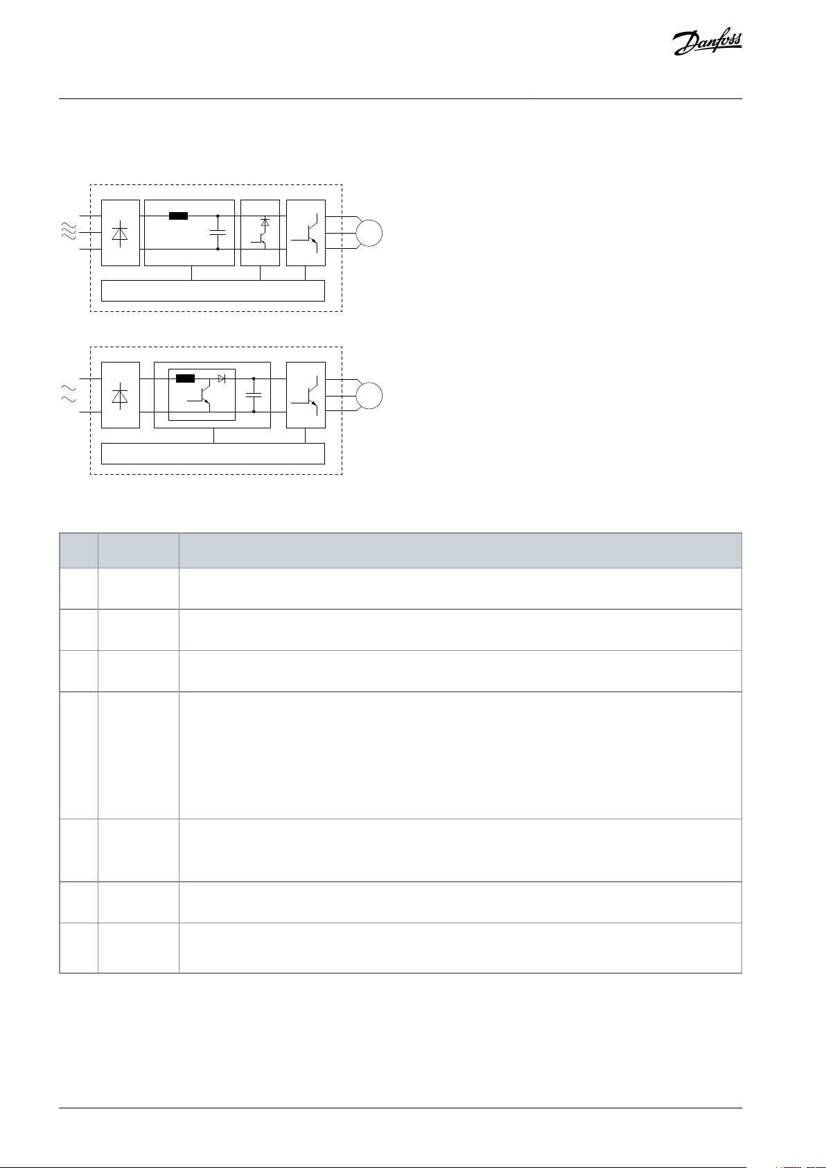
1
Mains input
AC mains supply to the drive.
2
Rectifier
The rectifier bridge converts the AC input to DC current to supply inverter power.
3
DC bus
Intermediate DC-bus circuit handles the DC current.
4
DC reactor
Filters the intermediate DC circuit current.
Provides mains transient protection.
Reduces the root mean square (RMS) current.
Raises the power factor reflected back to the line.
Reduces harmonics on the AC input.
5
Capacitor
bank
Stores the DC power.
Provides ride-through protection for short power losses.
6
Inverter
Converts the DC into a controlled PWM AC waveform for a controlled variable output to the motor.
7
Output to
motor
Regulated 3-phase output power to the motor.
VLT® Midi Drive FC 280
Operating Guide
1.4.2 Block Diagram of the Drive
Introduction
Illustration 1: Block Diagram of the Drive
Table 2: Functions of Each Component
AQ381425076031en-000101 / 130R122310 | Danfoss A/S © 2022.02
•
•
•
•
•
Area
Component
Functions
8
Control circuitry
Input power, internal processing, output, and motor current are monitored to provide efficient operation and control.
User interface and external commands are monitored and performed.
Status output and control can be provided.
9
PFC
Power factor correction changes the waveform of current which is drawn by the drive to improve the
power factor.
10
Brake chopper
Brake chopper is used in the DC intermediate circuit to control DC voltage when the load feeds energy back.
089
VLT® Midi Drive FC 280
Operating Guide
Introduction
1.4.3 Enclosure Sizes and Power Ratings
For enclosure sizes and power ratings of the drives, refer to 9.9 Enclosure Sizes, Power Ratings, and Dimensions.
1.4.4 Safety Functions
The following safety functions are integrated in this drive according to EN IEC 61800-5-2:
•
Safe Torque Off (STO).
•
Safe Stop 1 time controlled (SS1-t).
See Chapter 6 Safety Functions for details about the installation, configuration, commissioning, maintenance, and technical data.
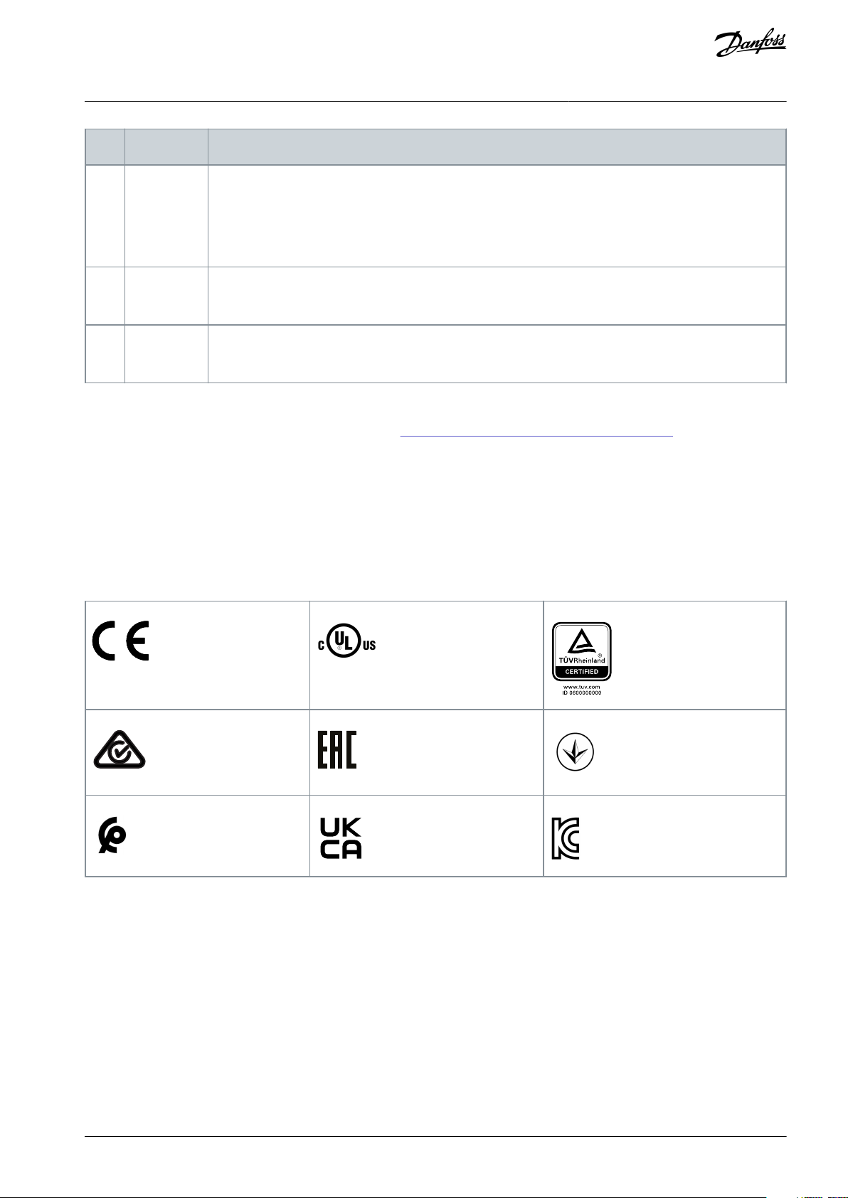
1.5 Approvals and Certifications
For compliance with the European Agreement concerning International Carriage of Dangerous Goods by Inland Waterways (ADN),
refer to the chapter ADN-compliant Installation in the VLT® Midi Drive FC 280 Design Guide.
The drive complies with UL 508C thermal memory retention requirements. For more information, refer to the chapter Motor Thermal Protection in the VLT® Midi Drive FC 280 Design Guide.
AQ381425076031en-000101 / 130R1223 | 11Danfoss A/S © 2022.02
Do not dispose of equipment containing electrical components together with domestic waste.
Collect it separately in accordance with local and currently valid legislation.
VLT® Midi Drive FC 280
Operating Guide
1.6 Applied Standards and Compliance for Safety Functions
Safe Torque Off (STO)
The STO function is designed and approved according to the following standards:
•
EN IEC 61508, SIL3
•
EN IEC 61800-5-2, SIL3
•
EN IEC 62061, SILCL of SIL3
•
EN ISO 13849-1, Category 3, PL e
Safe Stop 1 time controlled (SS1-t)
The SS1-t function is designed and approved according to the following standards:
•
EN IEC 61508, SIL3
•
EN IEC 61800-5-2, SIL3
•
EN IEC 62061, SILCL of SIL3
•
EN ISO 13849-1, Category 3, PL e
1.7 Disposal
Introduction
AQ381425076031en-000101 / 130R122312 | Danfoss A/S © 2022.02
VLT® Midi Drive FC 280
Operating Guide
2 Safety
2.1 Safety Symbols
The following symbols are used in this guide:
D A N G E R
Indicates a hazardous situation which, if not avoided, will result in death or serious injury.
W A R N I N G
Indicates a hazardous situation which, if not avoided, could result in death or serious injury.
C A U T I O N
Indicates a hazardous situation which, if not avoided, could result in minor or moderate injury.
N O T I C E
Indicates information considered important, but not hazard-related (for example, messages relating to property damage).
Safety
2.2 Qualified Personnel
Correct and reliable transport, storage, installation, operation, and maintenance are required for the trouble-free and safe operation
of the drive. Only qualified personnel are allowed to install and operate this equipment.
Qualified personnel are defined as trained staff, who are authorized to install, commission, and maintain equipment, systems, and
circuits in accordance with pertinent laws and regulations. Also, the qualified personnel must be familiar with the instructions and
safety measures described in this manual.
2.3 Safety Precautions
W A R N I N G
HAZARDOUS VOLTAGE
AC drives contain hazardous voltage when connected to the AC mains or connected on the DC terminals. Failure to perform
installation, start-up, and maintenance by qualified personnel can result in death or serious injury.
Only qualified personnel must perform installation, start-up, and maintenance.
-
W A R N I N G
UNINTENDED START
When the drive is connected to AC mains, DC supply, or load sharing, the motor may start at any time. Unintended start during
programming, service, or repair work can result in death, serious injury, or property damage. Start the motor with an external
switch, a fieldbus command, an input reference signal from the local control panel (LCP), via remote operation using MCT 10
software, or after a cleared fault condition.
Disconnect the drive from the mains.
-
Press [Off/Reset] on the LCP before programming parameters.
-
Ensure that the drive is fully wired and assembled when it is connected to AC mains, DC supply, or load sharing.
-
AQ381425076031en-000101 / 130R1223 | 13Danfoss A/S © 2022.02
Voltage [V]
Power range [kW (hp)]
Minimum waiting time (minutes)
200–240
0.37–3.7 kW (0.5–5 hp)
4
380–480
0.37–7.5 kW (0.5–10 hp)
4
11–22 kW (15–30 hp)
15
VLT® Midi Drive FC 280
Operating Guide
Safety
W A R N I N G
DISCHARGE TIME
The drive contains DC-link capacitors, which can remain charged even when the drive is not powered. High voltage can be
present even when the warning indicator lights are off.
Failure to wait the specified time after power has been removed before performing service or repair work could result in death or
serious injury.
Stop the motor.
-
Disconnect AC mains, permanent magnet type motors, and remote DC-link supplies, including battery back-ups, UPS, and
-
DC-link connections to other drives.
Wait for the capacitors to discharge fully. The minimum waiting time is specified in the table Discharge time and is also visible
-
on the nameplate on the top of the drive.
Before performing any service or repair work, use an appropriate voltage measuring device to make sure that the capacitors
-
are fully discharged.
Table 3: Discharge Time
W A R N I N G
ELECTRICAL SHOCK HAZARD - LEAKAGE CURRENT HAZARD >3.5 MA
Leakage currents exceed 3.5 mA. Failure to connect the drive properly to protective earth (PE) can result in death or serious injury.
Ensure reinforced protective earthing conductor according to IEC 60364-5-54 cl. 543.7 or according to local safety regula-
-
tions for high touch current equipment. The reinforced protective earthing of the drive can be done with:
a PE conductor with a cross-section of at least 10 mm2 (8 AWG) Cu or 16 mm2 (6 AWG) Al.
-
an extra PE conductor of the same cross-sectional area as the original PE conductor as specified by IEC 60364-5-54 with a
-
minimum cross-sectional area of 2.5 mm2 (14 AWG) (mechanical protected) or 4 mm2 (12 AWG) (not mechanical protected).
a PE conductor completely enclosed with an enclosure or otherwise protected throughout its length against mechanical
-
damage.
a PE conductor part of a multi-conductor power cable with a minimum PE conductor cross-section of 2.5 mm2 (14 AWG)
-
(permanently connected or pluggable by an industrial connector. The multi-conductor power cable shall be installed with an
appropriate strain relief).
NOTE: In IEC/EN 60364-5-54 cl. 543.7 and some application standards (for example IEC/EN 60204-1), the limit for requiring
-
reinforced protective earthing conductor is 10 mA leakage current.
W A R N I N G
EQUIPMENT HAZARD
Contact with rotating shafts and electrical equipment can result in death or serious injury.
Ensure that only trained and qualified personnel perform installation, start-up, and maintenance.
-
Ensure that electrical work conforms to national and local electrical codes.
-
Follow the procedures in this guide.
-
AQ381425076031en-000101 / 130R122314 | Danfoss A/S © 2022.02

VLT® Midi Drive FC 280
Operating Guide
C A U T I O N
INTERNAL FAILURE HAZARD
An internal failure in the drive can result in serious injury when the drive is not properly closed.
Ensure that all safety covers are in place and securely fastened before applying power.
-
Safety
AQ381425076031en-000101 / 130R1223 | 15Danfoss A/S © 2022.02
e30be616.15
VLT
MADE IN
DENMARK
T/C: FC-280PK37T4E20H1BXCXXXSXXXXAX
0.37kW 0.5HP
IN: 3x380-480V 50/60Hz, 1.2/1.0A
OUT: 3x0-Vin 0-500Hz, 1.2/1.1A
IP20 SIL3 PL.e
P/N: 134U2184 S/N: 000000G000
Midi Drive
www.danfoss.com
CAUTION / ATTENTION:
WARNING / AVERTISSEMENT:
See manual for special condition/mains fuse
Voir manual de conditions speciales/fusibles
Stored charge, wait 4 min.
Charge résiduelle, attendez 4 min.
21
1
2
4
3
5
11
20
19
18
16
15
13
10
8
9
6
17
R
US LISTED
www.tuv.com
ID 0600000000
Danfoss A/S, 6430 Nordborg, Denmark
12
7
SIL3
E358 502
See manual for mains fuse
IND.CON.EQ
5AF3
14
22
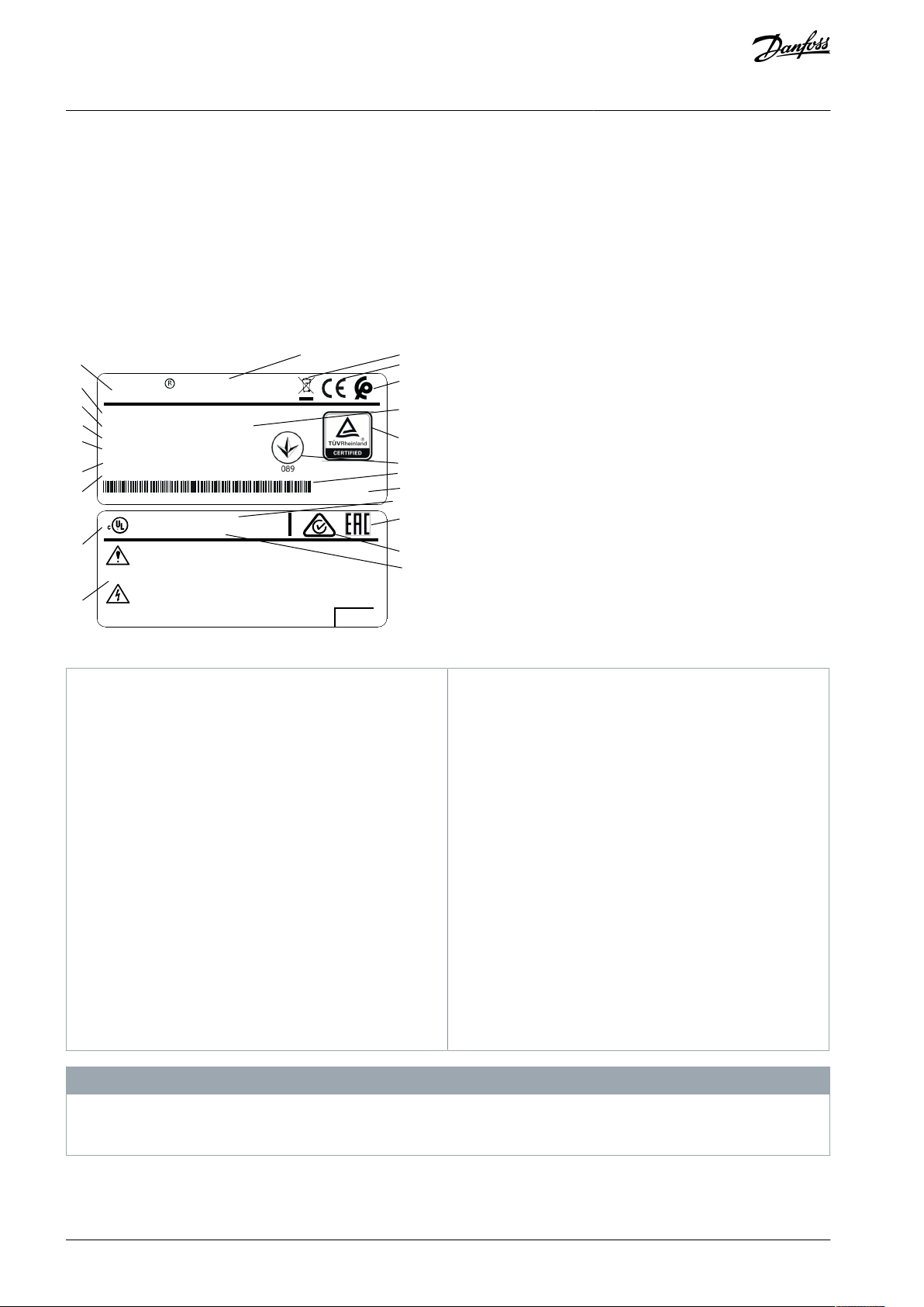
1
Product logo
2
Product name
3
Disposal
4
CE mark
5
Morocco
6
Serial number
7
TÜV logo
8
UkrSEPRO logo
9
Barcode
10
Country of origin
11
UL reference
12
EAC logo
13
RCM logo
14
Reference to enclosure type
15
Warning specifications
16
UL logo
17
IP rating
18
Output voltage, frequency, and current (at low/high
voltages)
19
Input voltage, frequency, and current (at low/high
voltages)
20
Power rating
21
Ordering number
22
Type code
VLT® Midi Drive FC 280
Operating Guide
Mechanical Installation
3 Mechanical Installation
3.1 Unpacking
3.1.1 Items Supplied
Items supplied vary according to product configuration.
•
Make sure that the items supplied and the information on the nameplate correspond to the order confirmation.
•
Check the packaging and the drive visually for damage caused by inappropriate handling during shipment. File any claim for
damage with the carrier. Retain damaged parts for clarification.
Illustration 2: Product Nameplate (Example)
Do not remove the nameplate from the drive (loss of warranty).
For more information of the type code, refer to the chapter Type Code in the VLT® Midi DriveFC 280 Design Guide.
-
N O T I C E
AQ381425076031en-000101 / 130R122316 | Danfoss A/S © 2022.02

- P
4
e30bu891.10
B C A X X X X
1 2 3 4 5 6 7 8 9 10 11 12 13 14 15 16 17 18 19 20 30 22 21 23 27 25 24 26 28 29
F0 C 2 1 X L
Pos.
S
FS1
H
0
E
T
K
3
7
8
2
VLT® Midi Drive FC 280
Operating Guide
Mechanical Installation
3.1.2 Identifying the Drive with Ethernet-based Safety Functions
To identify whether the drive is equipped with the Ethernet-based safety functions, check the following:
•
The drive's type code on the product label contains “SFS1” at bits 24~27, for example:
Illustration 3: Type Code Example for Drive with Ethernet-based Safety Functions
•
The drive has terminal 39.
3.1.3 Storage
Ensure that the requirements for storage are fulfilled. Refer to 9.4 Ambient Conditions for further details.
3.2 Installation Environment
N O T I C E
REDUCED LIFETIME
In environments with airborne liquids, particles, or corrosive gases, ensure that the IP/Type rating of the equipment matches the
installation environment. Failure to meet requirements for ambient conditions can reduce lifetime of the drive.
Ensure that requirements for air humidity, temperature, and altitude are met.
-
Vibration and shock
The drive complies with requirements for units mounted on the walls and floors of production premises, and in panels bolted to
walls or floors. For detailed ambient conditions, refer to 9.4 Ambient Conditions.
3.3 Mounting
3.3.1 Cooling
N O T I C E
Improper mounting can result in overheating and reduced performance.
•
Ensure 100 mm (3.9 in) of top and bottom clearance for air cooling.
3.3.2 Lifting
•
To determine a safe lifting method, check the weight of the unit, see 9.9 Enclosure Sizes, Power Ratings, and Dimensions.
•
Ensure that the lifting device is suitable for the task.
•
If necessary, plan for a hoist, crane, or forklift with the appropriate rating to move the unit.
•
For lifting, use hoist rings on the unit, when provided.
3.3.3 Mounting
Procedure
1.
Ensure that the strength of the mounting location supports the unit weight.
2.
Place the unit as near to the motor as possible. Keep the motor cables as short as possible.
3.
Mount the unit vertically on a solid flat surface.
4.
Use the slotted mounting holes on the unit for wall mount, when provided. For dimensions of mounting holes, see 9.9
Enclosure Sizes, Power Ratings, and Dimensions.
3.3.3.1 Side-by-side Installation
All VLT® Midi Drive FC 280 units can be installed side by side in vertical or horizontal position. The units do not require extra ventilation on the side.
AQ381425076031en-000101 / 130R1223 | 17Danfoss A/S © 2022.02
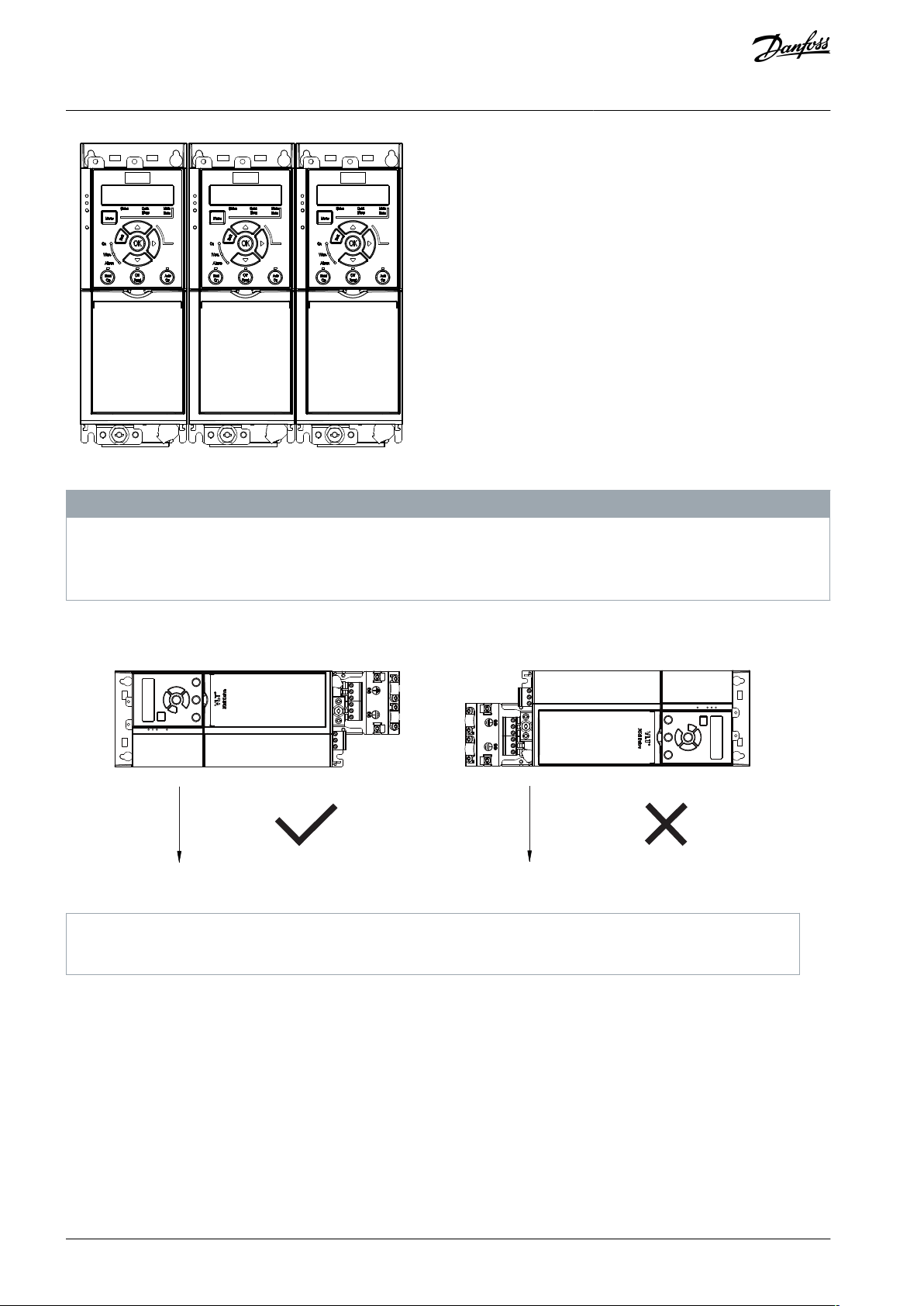
e30be615.12
e30bf642.10
G
G
(1)
(2)
1
Correct horizontal mounting (left side downwards)
2
Incorrect horizontal mounting (right side downwards)
VLT® Midi Drive FC 280
Operating Guide
Illustration 4: Side-by-side Installation
Mechanical Installation
N O T I C E
RISK OF OVERHEATING
If IP21 conversion kit is used, mounting the units side by side could lead to overheating and damage to the unit.
At least 30 mm (1.2 in) is required between the top cover edges of IP21 conversion kit.
-
3.3.3.2 Horizontal Mounting
Illustration 5: Horizontal Mounting
3.3.3.3 Bus Decoupling Kit
The bus decoupling kit ensures mechanical fixation and electrical shielding of cables for the control cassettes with PROFINET/PROFISAFE.
Each bus decoupling kit contains 1 horizontal decoupling plate and 1 vertical decoupling plate. Mounting the vertical decoupling
plate is optional. The vertical decoupling plate provides better mechanical support for Ethernet connectors and cables.
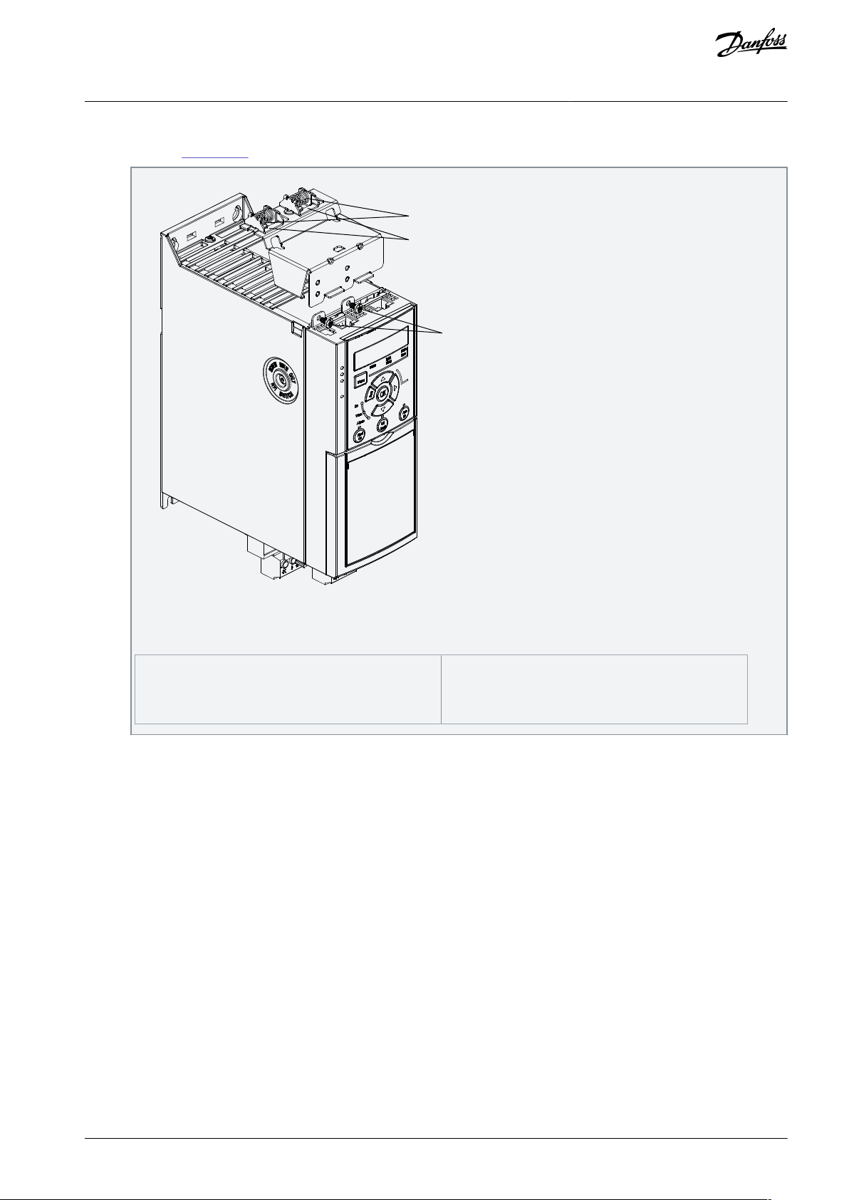
3.3.3.4 Mounting the Bus Decoupling Kit
Procedure
AQ381425076031en-000101 / 130R122318 | Danfoss A/S © 2022.02
1
2
3
e30be480.10
1
Mechanical springs
2
Metal clamps
3
Screws
VLT® Midi Drive FC 280
Operating Guide
1.
Place the horizontal decoupling plate on the control cassette mounted on the drive and fasten the plate using 2 screws as
shown in Illustration 6. Tightening torque is 0.7–1.0 Nm (6.2–8.9 in-lb).
Mechanical Installation
Illustration 6: Fasten the Horizontal Decoupling Plate with Screws
The illustration shows Ethernet-based connectors (RJ45). The actual connector type depends on the selected fieldbus variant of the drive.
2.
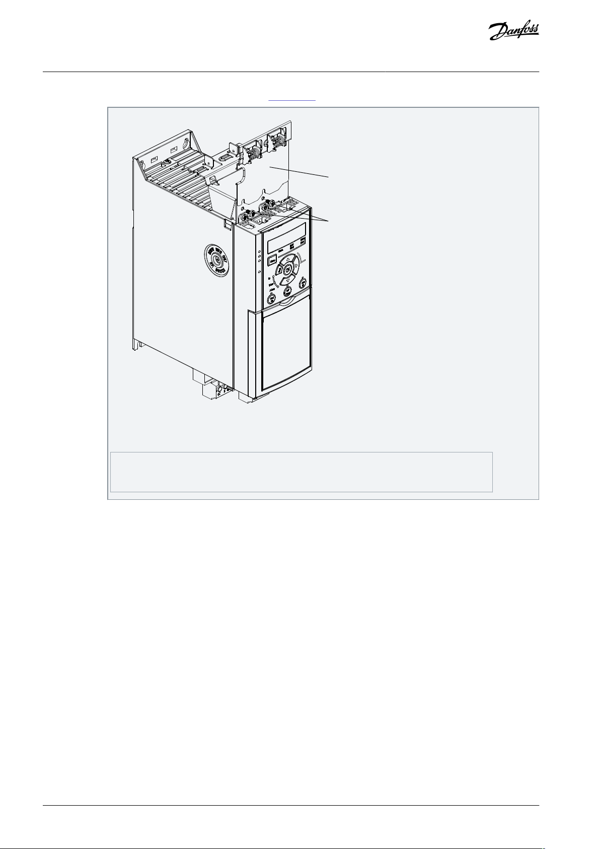
Optional: Mount the vertical decoupling plate as follows:
a.
Remove the 2 mechanical springs and 2 metal clamps from the horizontal plate.
b.
Mount the mechanical springs and metal clamps on the vertical plate.
AQ381425076031en-000101 / 130R1223 | 19Danfoss A/S © 2022.02
e30be481.10
1
2
1
Vertical decoupling plate
2
Screws
VLT® Midi Drive FC 280
Operating Guide
c.
Mechanical Installation
Fasten the plate with 2 screws as shown in Illustration 7. Tightening torque is 0.7–1.0 Nm (6.2–8.9 in-lb).
Illustration 7: Fasten the Vertical Decoupling Plate with Screws
The illustration shows Ethernet-based connectors (RJ45). The actual connector type depends on the selected
fieldbus variant of the drive.
3.
Push the Ethernet cable connectors (RJ45) into the sockets in the control cassette.
4.
Place the Ethernet cables between the springloaded metal clamps to establish mechanical fixation between the cables and
the clamps.
AQ381425076031en-000101 / 130R122320 | Danfoss A/S © 2022.02

VLT® Midi Drive FC 280
Operating Guide
Electrical Installation
4 Electrical Installation
4.1 Safety Instructions
See chapter Safety for general safety instructions.
W A R N I N G
INDUCED VOLTAGE
Induced voltage from output motor cables that run together can charge equipment capacitors, even with the equipment turned
off and locked out/tagged out. Failure to run output motor cables separately or to use shielded cables could result in death or
serious injury.
Run output motor cables separately or use shielded cables.
-
Simultaneously lock out/tag out all the drives.
-
W A R N I N G
ELECTRICAL SHOCK AND FIRE HAZARD – RCD COMPLIANCE
The drive can cause a DC fault current in the PE conductor. Failure to use a Type B residual current-operated protective device
(RCD) can lead to the RCD not providing the intended protection and therefore can result in death, fire, or other serious hazard.
When an RCD is used for protection against electrical shock or against fire, only a Type B device is allowed on the supply side.
-
Overcurrent protection
•
Extra protective equipment, such as short-circuit protection or motor thermal protection between drive and motor, is required
for applications with multiple motors.
•
Input fusing is required to provide short-circuit and overcurrent protection. If not factory-supplied, the installer must provide
fuses. See maximum fuse ratings in chapter Fuses and Circuit Breakers.
Wire type and ratings
All wiring must comply with local and national regulations regarding cross-section and ambient temperature requirements.
•
Power connection wire recommendation: Minimum 75 °C (167 °F) rated copper wire. See
•
mended wire sizes and types.
9.5 Cable Specifications for recom-
4.2 EMC-compliant Installation
To obtain an EMC-compliant installation, follow the instructions provided in 4.3 Grounding, 4.4 Wiring Schematic, 4.7 Connecting
the Motor, and chapter Control Wiring.
AQ381425076031en-000101 / 130R1223 | 21Danfoss A/S © 2022.02
e30bc500.12
FC 1
FC 1
FC 2
FC 2
FC 3
FC 3
PE
PE
A
B
VLT® Midi Drive FC 280
Operating Guide
Electrical Installation
4.3 Grounding
W A R N I N G
ELECTRICAL SHOCK HAZARD - LEAKAGE CURRENT HAZARD >3.5 MA
Leakage currents exceed 3.5 mA. Failure to connect the drive properly to protective earth (PE) can result in death or serious injury.
Ensure reinforced protective earthing conductor according to IEC 60364-5-54 cl. 543.7 or according to local safety regula-
-
tions for high touch current equipment. The reinforced protective earthing of the drive can be done with:
a PE conductor with a cross-section of at least 10 mm2 (8 AWG) Cu or 16 mm2 (6 AWG) Al.
-
an extra PE conductor of the same cross-sectional area as the original PE conductor as specified by IEC 60364-5-54 with a
-
minimum cross-sectional area of 2.5 mm2 (14 AWG) (mechanical protected) or 4 mm2 (12 AWG) (not mechanical protected).
a PE conductor completely enclosed with an enclosure or otherwise protected throughout its length against mechanical
-
damage.
a PE conductor part of a multi-conductor power cable with a minimum PE conductor cross-section of 2.5 mm2 (14 AWG)
-
(permanently connected or pluggable by an industrial connector. The multi-conductor power cable shall be installed with an
appropriate strain relief).
NOTE: In IEC/EN 60364-5-54 cl. 543.7 and some application standards (for example IEC/EN 60204-1), the limit for requiring
-
reinforced protective earthing conductor is 10 mA leakage current.
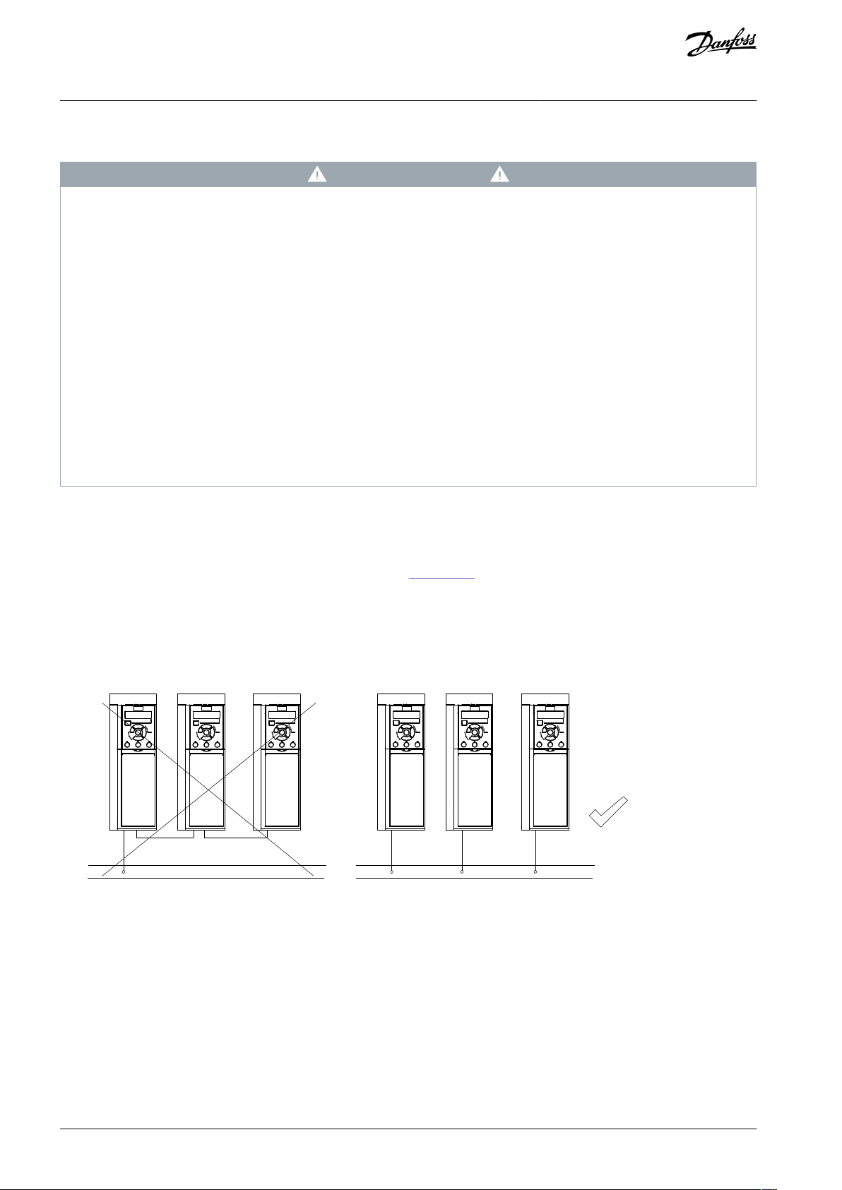
For electrical safety
Ground the drive in accordance with applicable standards and directives.
•
Use a dedicated ground wire for input power, motor power, and control wiring.
•
Do not ground 1 drive to another in a daisy chain fashion (see
•
•
Keep the ground wire connections as short as possible.
•
Follow motor manufacturer wiring requirements.
•
Minimum cable cross-section for the ground wires: 10 mm2 (7 AWG).
•
Separately terminate individual ground wires, both complying with the dimension requirements.
Illustration 8).
Illustration 8: Grounding Principle
For EMC-compliant installation
•
Establish electrical contact between the cable shield and the drive enclosure by using metal cable glands or by using the clamps
provided on the equipment.
•
Use high-strand wire to reduce burst transient.
•
Do not use pigtails.
AQ381425076031en-000101 / 130R122322 | Danfoss A/S © 2022.02
Power
input
Switch mode
power supply
Motor
interface
(PNP) = Source
(NPN) = Sink
Brake
resistor
91 (L1/N)
92 (L2/L)
93 (L3)
PE
13 (+24 V OUT)
18 (D IN)
100 mA
+
-
(U) 96
(V) 97
(W) 98
(PE) 99
(P RS485) 68
(N RS485) 69
(COM RS485) 61
RS485
RS485
03
+10 V DC
0−10 V DC
24 V DC
02
01
24 V (NPN)
0 V (PNP)
24 V (NPN)
0 V (PNP)
17 V
0 V
24 V (NPN)
0 V (PNP)
0 V (PNP)
24 V (NPN)
33 (D IN)
32 (D IN)
38 (SI B)
1)
37 (SI A)
1)
95
P 5-00
(+DC/R+) 89
(R-) 81
(-DC) 88
RFI
0 V
250 V AC, 3 A
Relay 1
2)
3)
3)
e30bu940.10
27 (D IN/OUT)
4)
50 (+10 V OUT)
53 (A IN)
5)
55 (COM digital/analog I/O)
10 V DC
15 mA
+ -
Safety input
interface
39 (Safe GND)
20
12
COM safe input
6)
VLT® Midi Drive FC 280
Operating Guide
Electrical Installation
N O T I C E
POTENTIAL EQUALIZATION
Risk of burst transient when the ground potential between the drive and the control system is different. Install equalizing cables
between the system components. Recommended cable cross-section: 16 mm2 (6 AWG).
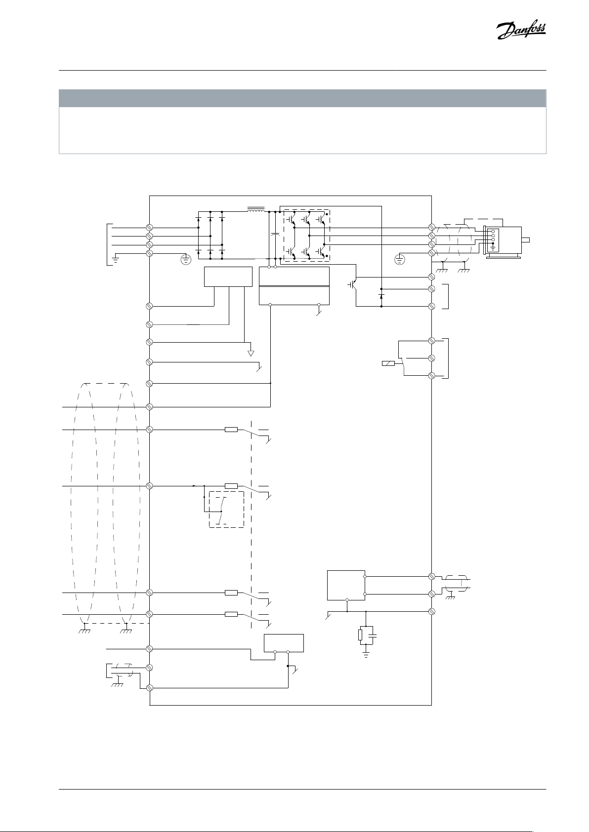
4.4 Wiring Schematic
Illustration 9: Basic Wiring Schematic
AQ381425076031en-000101 / 130R1223 | 23Danfoss A/S © 2022.02
A
Analog
D
Digital
1
Refer to chapter 6 Safety Functions for the correct
safety functions wiring.
2
Built-in brake chopper is only available on 3-phase
units.
3
The S2 (single-phase 200–240 V) drive does not support load sharing application.
4
The maximum voltage is 17 V for terminal 27 as analog output.
5
Terminal 53 can also be used as digital input.
6
Terminal 61 is internally connected to terminal 20
and 55.
L1
L2L3PEL1L2L3PEPEu
v
w
2
1
3
5
IEC 60309
16
17
18
14
12
8
7
10
9
4
11
13
446
15
90
+DC
BR-
B
M
AINS
L1 L2 L3
91 92 93
RELA
Y 1 RELA
Y 2
99
- L
C -
UV
W
MO
T
OR
VLT® Midi Drive FC 280
Operating Guide
Electrical Installation
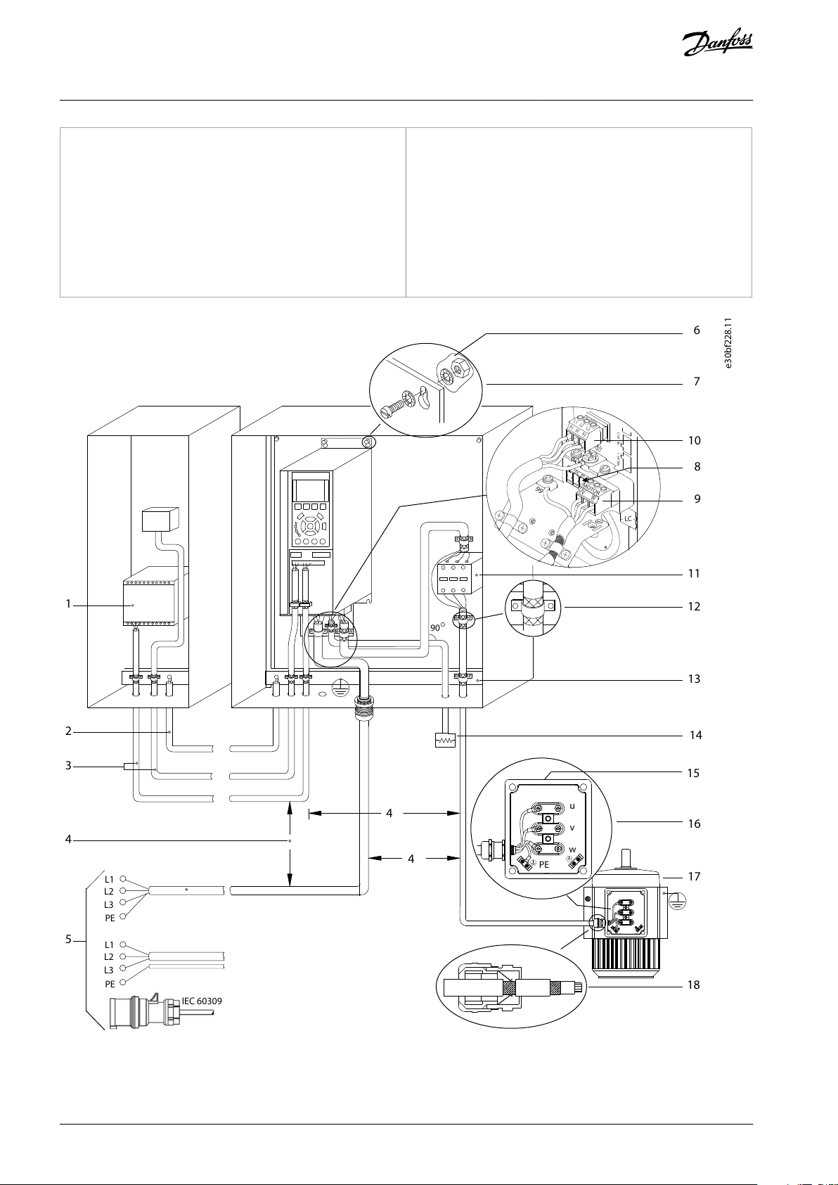
Illustration 10: Typical Electrical Connection
AQ381425076031en-000101 / 130R122324 | Danfoss A/S © 2022.02
1
PLC
2
Minimum 16 mm2 (6 AWG) equalizing cable
3
Control cables
4
Minimum 200 mm (7.87 in) between control cables,
motor cables, and mains cables.
5
Mains supply
6
Bare (unpainted) surface
7
Star washers
8
Brake cable (shielded)
9
Motor cable (shielded)
10
Mains cable (unshielded)
11
Output contactor, and more.
12
Cable insulation stripped
13
Common ground busbar. Follow local and national
requirements for cabinet grounding.
14
Brake resistor
15
Metal box
16
Connection to motor
17
Motor
18
EMC cable gland
e30bc504.11
VLT® Midi Drive FC 280
Operating Guide
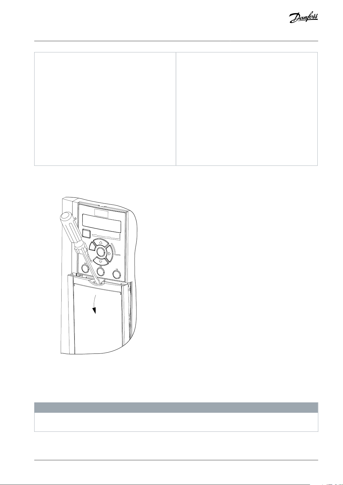
4.5 Control Wiring Access
•
Remove the cover plate with a screwdriver. See the following illustration.
Electrical Installation
Illustration 11: Control Wiring Access
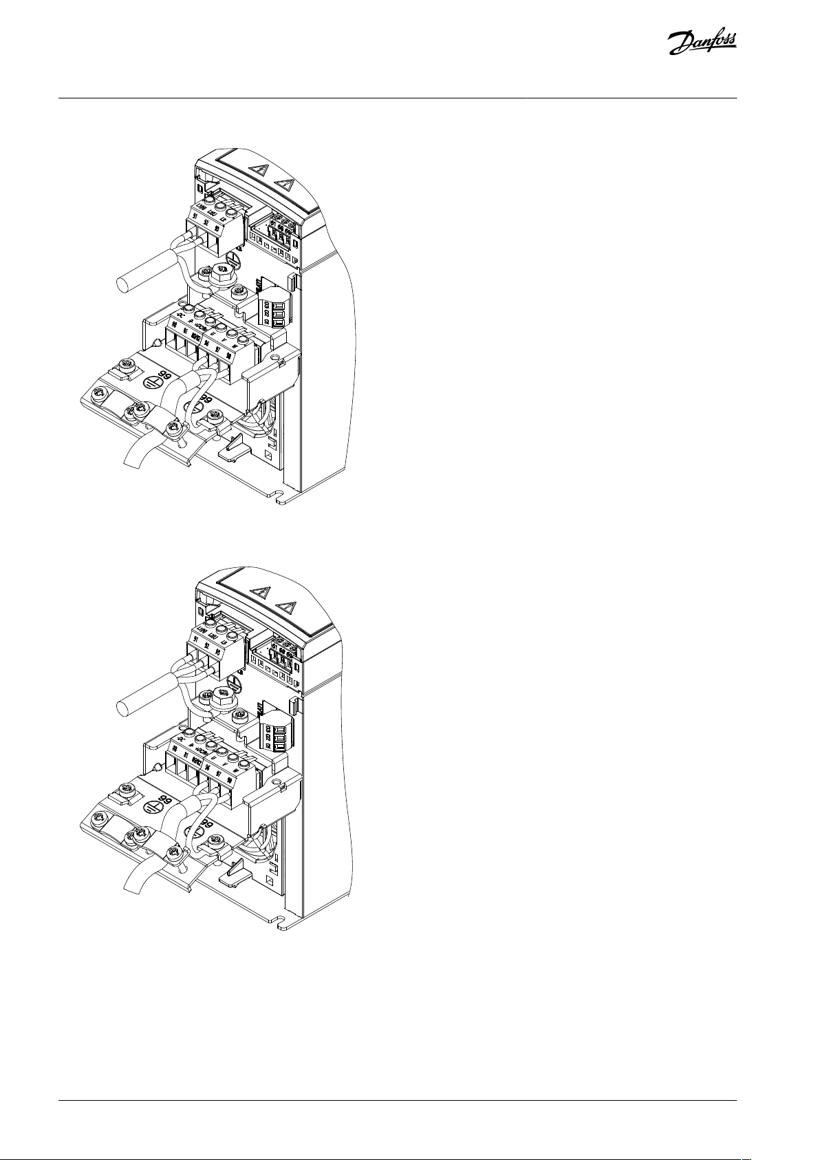
4.6 Examples of Mains, Motor, and Grounding Connection
The mains, motor, and grounding connection for single-phase and 3-phase drives are shown in the following illustrations respectively. Actual configurations vary with unit types and optional equipment.
In motors without phase insulation, paper, or other insulation reinforcement suitable for operation with voltage supply, use a
sine-wave filter on the output of the drive.
N O T I C E
AQ381425076031en-000101 / 130R1223 | 25Danfoss A/S © 2022.02
e30bu973.10
e30bu974.10
VLT® Midi Drive FC 280
Operating Guide
Electrical Installation
Illustration 12: Example of Mains, Motor, and Grounding Connection for Single-phase Units (K1, K2)
Illustration 13: Example of Mains, Motor, and Grounding Connection for 3-phase Units (K1, K2, K3)
AQ381425076031en-000101 / 130R122326 | Danfoss A/S © 2022.02
e30be804.10
VLT® Midi Drive FC 280
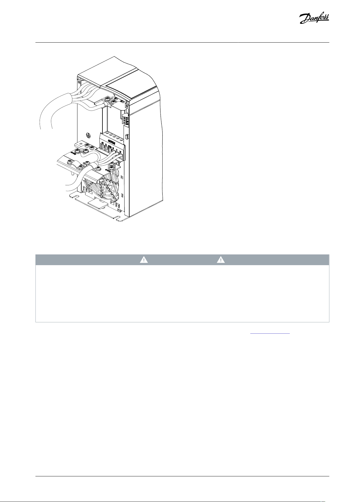
Operating Guide
Electrical Installation
Illustration 14: Example of Mains, Motor, and Grounding Connection for 3-phase Units (K4, K5)
4.7 Connecting the Motor
W A R N I N G
INDUCED VOLTAGE
Induced voltage from output motor cables that run together can charge equipment capacitors, even with the equipment turned
off and locked out/tagged out. Failure to run output motor cables separately or to use shielded cables could result in death or
serious injury.
Run output motor cables separately or use shielded cables.
-
Simultaneously lock out/tag out all the drives.
-
•
Comply with local and national electrical codes for cable sizes. For maximum cable sizes, see 9.1 Electrical Data.
•
Follow motor manufacturer wiring requirements.
•
Motor wiring knockouts or access panels are provided at the base of IP21/Type 1 units.
•
Do not wire a starting or pole-changing device (for example, Dahlander motor or slip ring induction motor) between the drive
and the motor.
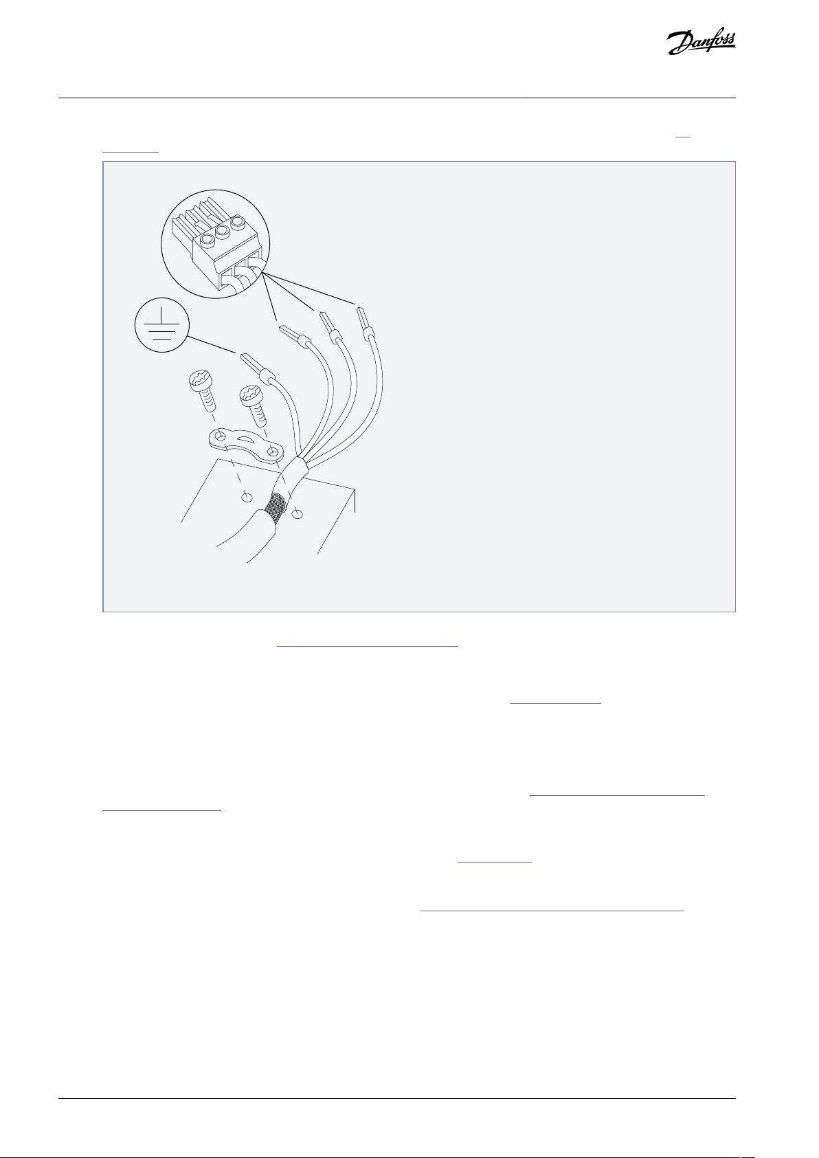
4.7.1 Grounding the Cable Shield
Procedure
1.
Strip a section of the outer cable insulation.
2.
Position the stripped wire under the cable clamp to establish mechanical fixation and electrical contact between the cable
shield and ground.
AQ381425076031en-000101 / 130R1223 | 27Danfoss A/S © 2022.02
e30bd531.11
U
V
W
96
97
98
VLT® Midi Drive FC 280
Operating Guide
3.
Connect the ground wire to the nearest grounding terminal in accordance with the grounding instructions, see 4.3
Grounding.
Electrical Installation
Illustration 15: Motor Connection
4.
Connect the 3-phase motor wiring to terminals 96 (U), 97 (V), and 98 (W).
5.
Torque-tighten the terminals, see 9.7 Connection Tightening Torques.
4.8 Connecting AC Mains
•
Size the wiring based on the input current of the drive. For maximum wire sizes, see 9.1 Electrical Data.
•
Comply with local and national electrical codes for cable sizes.
4.8.1 Connecting the Drive to Mains
Procedure
1.
Connect the AC input power cables to terminals N and L for single-phase units (see 4.6 Examples of Mains, Motor, and
Grounding Connection).
2.
3.
4.
Depending on the configuration of the equipment, connect the input power to the mains input terminals or the input disconnect.
Ground the cable in accordance with the grounding instructions, see 4.3 Grounding.
When supplied from an isolated mains source (IT mains or floating delta) or TT/TN-S mains with a grounded leg (grounded
delta), ensure that the RFI filter screw is removed. Removing the RFI screw prevents damage to the DC link and reduces
ground capacity currents in accordance with IEC 61800-3 (see 9.9 Enclosure Sizes, Power Ratings, and Dimensions, the RFI
screw is on the side of the drive).
AQ381425076031en-000101 / 130R122328 | Danfoss A/S © 2022.02
e30bu975.10
1
2
3
e30bu976.10
1 2
3
37
38 39 20 12
13
18 27
32
33 50 53
55
61 68 69
Terminal
Parameter
Default setting
Description
Digital I/O, pulse I/O, encoder
12, 13
–
+24 V DC
24 V DC supply voltage. Maximum output current is 100
mA for all 24 V loads.
18
Parameter 5-10 Terminal 18 Digital Input
[8] Start
Digital inputs.
27
Parameter 5-01 Terminal 27 Mode,
parameter 5-12 Terminal 27 Digital Input, parameter 5-30 Terminal
27 Digital Output
DI [2] Coast inverse
DO [0] No opera-
tion
Selectable for either digital input, digital output, or pulse
output. The default setting is digital input.
32
Parameter 5-14 Terminal 32 Digital Input
[0] No operation
Digital input, 24 V encoder. Terminal 33 can be used for
pulse input.
33
Parameter 5-15 Terminal 33 Digital Input
[0] No operation
37, 38
Parameter 42-20 Safe Function
[5] Disable
Functional safety inputs.
39––
Function safety COM ground.
Analog inputs/outputs
50
–
+10 V DC
10 V DC analog supply voltage. 15 mA maximum commonly used for potentiometer or thermistor.
53
Parameter group 6-1* Analog Input 53
–
Analog input. Only voltage mode is supported. It can also
be used as digital input.
VLT® Midi Drive FC 280
Operating Guide
4.9 Control Wiring
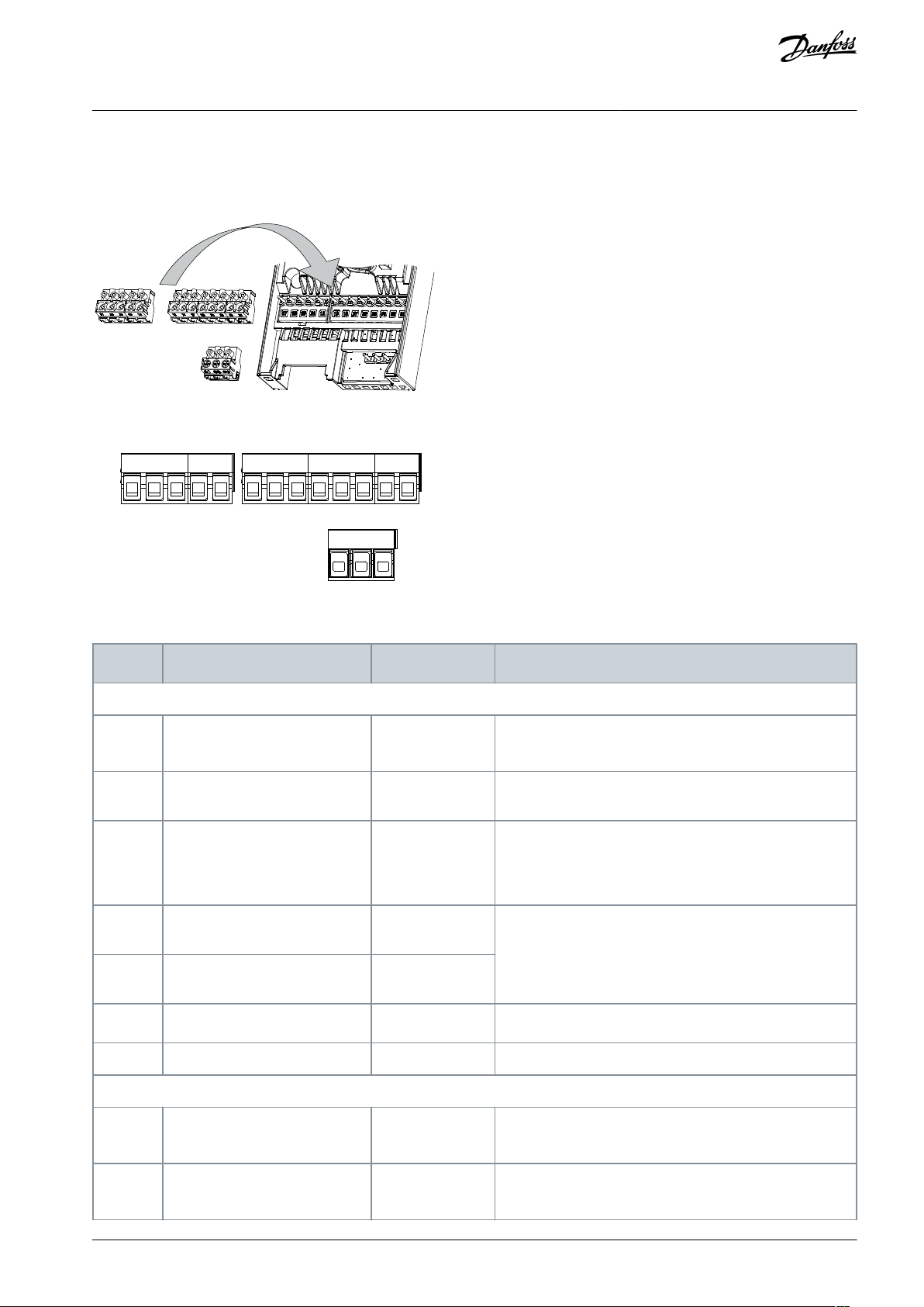
4.9.1 Control Terminal Types
Illustration 16: Control Terminal Locations
Electrical Installation
Illustration 17: Terminal Numbers
Table 4: Terminal Descriptions
AQ381425076031en-000101 / 130R1223 | 29Danfoss A/S © 2022.02
Terminal
Parameter
Default setting
Description
55, 20
––Common for digital and analog inputs.
Serial communication
61––
Connected to digital/analog ground internally.
68 (+)
Parameter group 8-3* FC Port Settings
–
RS485 interface. A control card switch is provided for termination resistance.
69 (-)
Parameter group 8-3* FC Port Settings–Relays
01, 02, 03
Parameter 5-40 Function Relay
[1] Control Ready
Form C relay output. These relays are in various locations
depending on the drive configuration and size. Usable for
AC or DC voltage and resistive or inductive loads.
VLT® Midi Drive FC 280
Operating Guide
Electrical Installation
4.9.2 Wiring to Control Terminals
Control terminal connectors can be unplugged from the drive for ease of installation, as shown in 4.9.1 Control Terminal Types.
For details about safety functions wiring, refer to chapter 6 Safety Functions. See 9.5 Cable Specifications for control terminal cable
sizes and chapter Application Examples for typical control cable connections.
N O T I C E
Keep control cables as short as possible and separate them from high-power cables to minimize interference.
4.9.2.1 Wiring
Procedure
1.
Loosen the screws for the terminals.
2.
Insert sleeved control cables into the slots.
3.
Fasten the screws for the terminals.
4.
Ensure that the contact is firmly established and not loose. Loose control wiring can be the source of equipment faults or
less than optimal operation.
4.9.3 Enabling Motor Operation (Terminal 27)
A jumper wire is required between terminal 12 (or 13) and terminal 27 for the drive to operate when using factory default programming values.
•
Digital input terminal 27 is designed to receive 24 V DC external interlock command.
•
When no interlock device is used, wire a jumper between control terminal 12 (recommended) or 13 to terminal 27. The jumper
provides an internal 24 V signal on terminal 27.
•
Only for GLCP: When the status line at the bottom of the LCP reads AUTO REMOTE COAST, it indicates that the unit is ready to
operate but is missing an input signal on terminal 27.
N O T I C E
UNABLE TO START
The drive cannot operate without a signal on terminal 27, unless terminal 27 is reprogrammed.
AQ381425076031en-000101 / 130R122330 | Danfoss A/S © 2022.02

Start Current
2)
Only support in some products.
1)
DC injection current during “Active Brake Delay” after MAV reduced to “0” . Only support in some products.
Off
On
Off
Relay / DO Status
Active Brake Delay
Active Brake Delay
MAV
Start Speed
Active Brake Speed
0
t
Start Delay
Off
On
Off
Start Command
Released
Activated
Reaction time of
mech. brake
Reaction time of
mech. brake
Mech . Brake Status
Release Brake Current
Output Current
DC Injection Current
1)
0
t
e30bf687.10
Activated
Note:
2)
VLT® Midi Drive FC 280
Operating Guide
Electrical Installation
4.9.4 Mechanical Brake Control
In hoisting/lowering applications, it is necessary to control an electro-mechanical brake.
•
Control the brake using any relay output or digital output (terminal 27).
•
Keep the output closed (voltage-free) as long as the drive is unable to keep the motor at standstill, for example due to the load
being too heavy.
•
Select [32] Mechanical brake control in parameter group 5-4* Relays for applications with an electro-mechanical brake.
•
The brake is released when the motor current exceeds the preset value in parameter 2-20 Release Brake Current.
•
The brake is engaged when the output frequency is less than the frequency set in parameter 2-22 Activate Brake Speed [Hz], and
only if the drive carries out a stop command.
If the drive is in 1 of the following situations, the mechanical brake immediately closes.
In alarm mode.
•
In an overvoltage situation.
•
STO is activated.
•
Coast command is given.
•
Illustration 18: Mechanical Brake
The drive is not a safety device. It is the responsibility of the system designer to integrate safety devices according to relevant national crane/lift regulations.
AQ381425076031en-000101 / 130R1223 | 31Danfoss A/S © 2022.02

e30be201.12
L1(N) L2(L) L3
U V W
02 01
A1
A2
Drive
Output
relay
Command circuit
220 V AC
Mechanical
brake
ShaftMotor
Freewheeling
diode
Brake power circuit
380 V AC
Output
contactor
input
e30bt623.12
VLT® Midi Drive FC 280
Operating Guide
Illustration 19: Connecting the Mechanical Brake to the Drive
Electrical Installation
4.9.5 USB Data Communication
Illustration 20: Network Bus List
When the USB cable is disconnected, the drive connected via the USB port is removed from the Network bus list.
N O T I C E
CONNECT 1 DRIVE VIA USB TO PC
A USB bus has no address-setting capacity and no bus name to configure. If connecting more than 1 drive through USB, the bus
name is auto-incremented in the MCT 10 Set-up Software Network bus list.
Connecting more than 1 drive through a USB cable often causes computers installed with Windows to throw an exception and
crash.
-
4.9.6 Serial Communication
Connect RS485 serial communication wiring to terminals (+) 68 and (-) 69.
•
•
Only connect 1 drive via USB to the PC.
Shielded serial communication cable is recommended.
See 4.3 Grounding for proper grounding.
AQ381425076031en-000101 / 130R122332 | Danfoss A/S © 2022.02

•
•
•
•
•
•
•
•
•
61
68
69
+
e30bb489.10
RS485
Inspect for
Description
✓
Auxiliary equipment
Look for auxiliary equipment, switches, disconnects, or input fuses/circuit breakers, residing on the
input power side of the drive, or output side to the motor. Ensure that they are ready for full-speed
operation.
Check the function and installation of any sensors used for feedback to the drive.
Remove any power factor correction capacitors on the motor.
Adjust any power factor correction capacitors on the mains side and ensure that they are dampened.
Cable routing
Ensure that the motor wiring and control wiring are separated, shielded, or in 3 separate metallic conduits for high frequency interference isolation.
Control wiring
Check for broken or damaged wires and loose connections.
Check that the control wiring is isolated from power and motor wiring for noise immunity.
Check the voltage source of the signals, if necessary.
The use of shielded cable or twisted pair is recommended. Ensure that the shield is terminated correctly.
Cooling clearance
Ensure that the top and bottom clearance is adequate to ensure proper airflow for cooling, see chap-
ter Mounting.
VLT® Midi Drive FC 280
Operating Guide
Illustration 21: Serial Communication Wiring Diagram
Electrical Installation
For basic serial communication set-up, select the following:
•
Protocol type in parameter 8-30 Protocol.
•
Drive address in parameter 8-31 Address.
•
Baud rate in parameter 8-32 Baud Rate.
Two communication protocols are internal to the drive.
Danfoss FC
•
Modbus RTU
•
Follow motor manufacturer wiring requirements.
Functions can be programmed remotely using the protocol software and RS485 connection, or in parameter group 8-** Communica-
tions and Options.
Selecting a specific communication protocol changes various default parameter settings to match the specifications of the protocol
and makes extra protocol-specific parameters available.
4.10 Installation Check List
Before completing installation of the unit, inspect the entire installation as detailed in
completed.
Table 5: Installation Check List
Table 5. Check and mark the items when
AQ381425076031en-000101 / 130R1223 | 33Danfoss A/S © 2022.02

•
•••
•••••
•••
Inspect for
Description
✓
Ambient conditions
Check that requirements for ambient conditions are met.
Fusing and circuit breakers
Check for proper fusing or circuit breakers.
Check that all fuses are inserted firmly and are in operational condition, and that all circuit breakers
are in the open position.
Grounding
Check for sufficient ground connections and ensure that those connections are tight and free of oxidation.
Grounding to conduit, or mounting the back panel to a metal surface, is not a suitable grounding.
Input and output power wiring
Check for loose connections.
Check that the motor and mains cables are in separate conduit or separated shielded cables.
Panel interior
Inspect that the unit interior is free of dirt, metal chips, moisture, and corrosion.
Check that the unit is mounted on an unpainted metal surface.
Switches
Ensure that all switch and disconnect settings are in the proper positions.
Vibration
Check that the unit is mounted solidly, or that shock mounts are used, as necessary.
Check for an unusual amount of vibration.
VLT® Midi Drive FC 280
Operating Guide
Electrical Installation
C A U T I O N
INTERNAL FAILURE HAZARD
An internal failure in the drive can result in serious injury when the drive is not properly closed.
Ensure that all safety covers are in place and securely fastened before applying power.
-
AQ381425076031en-000101 / 130R122334 | Danfoss A/S © 2022.02

VLT® Midi Drive FC 280
Operating Guide
Commissioning
5 Commissioning
5.1 Safety Instructions
See chapter Safety for general safety instructions.
W A R N I N G
HAZARDOUS VOLTAGE
AC drives contain hazardous voltage when connected to the AC mains or connected on the DC terminals. Failure to perform
installation, start-up, and maintenance by qualified personnel can result in death or serious injury.
Only qualified personnel must perform installation, start-up, and maintenance.
-
N O T I C E
The front covers with warning signs are an integrated part of the drive and considered safety covers. The covers must be in place
before applying power and at all times.
5.1.1 Before Applying Power
Procedure
1.
Close the safety cover properly.
2.
Check that all cable glands are firmly tightened.
3.
Ensure that input power to the unit is off and locked out. Do not rely on the drive disconnect switches for input power
isolation.
4.
Verify that there is no voltage on input terminals L1 (91), L2 (92), and L3 (93), phase-to-phase, and phase-to-ground.
5.
Verify that there is no voltage on output terminals 96 (U), 97 (V), and 98 (W), phase-to-phase, and phase-to-ground.
6.
Confirm continuity of the motor by measuring Ω values on U–V (96–97), V–W (97–98), and W–U (98–96).
7.
Check for proper grounding of the drive and the motor.
8.
Inspect the drive for loose connections on the terminals.
9.
Confirm that the supply voltage matches the voltage of the drive and the motor.
5.2 Applying Power
Procedure
1.
Confirm that the input voltage is balanced within 3%. If not, correct the input voltage imbalance before proceeding. Repeat
this procedure after the voltage correction.
2.
Ensure that any optional equipment wiring matches the installation application.
3.
Ensure that all operator devices are in the OFF position. Panel doors must be closed and covers securely fastened.
4.
Apply power to the unit. Do not start the drive now. For units with a disconnect switch, turn it to the ON position to apply
power to the drive.
5.3 Local Control Panel Operation
5.3.1 Introduction
The drive supports numerical local control panel (NLCP), graphic local control panel (GLCP), and blind cover. This section describes
the operations with NLCP and GLCP.
N O T I C E
The drive can also be programmed from the MCT-10 Set-up Software on PC via RS485 com-port. This software can be or-
-
dered using code number 130B1000 or downloaded from the Danfoss website: www.danfoss.com/en/service-and-support/
downloads/dds/vlt-motion-control-tool-mct-10/#tab-downloads.
AQ381425076031en-000101 / 130R1223 | 35Danfoss A/S © 2022.02

e30bc506.10
Setup 1
A
B
C
D
5
12
13
14
15
10
11
10
9
6
7
8
4
1
2
3
Menu
Sta
tus
Quick
Menu
Main
Menu
Hand
On
Off
Reset
Auto
On
Back
OK
On
Warn
Alarm
Number
Function
1
The set-up number shows the active set-up and the edit set-up. If the same set-up acts as both active and edit set-up,
only that set-up number is shown (factory setting). When active and edit set-ups differ, both numbers are shown in
the display (set-up 12). The number flashing indicates the edit set-up.
2
Parameter number.
3
Parameter value.
4
Motor direction is shown at the bottom left of the display. A small arrow indicates the direction.
5
The triangle indicates whether the LCP is in Status, Quick Menu, or Main Menu.
VLT® Midi Drive FC 280
Operating Guide
5.3.2 Numerical Local Control Panel
The numerical local control panel is divided into 4 functional sections.
•
A. Numeric display.
•
B. Menu key.
•
C. Navigation keys and indicator lights (LEDs).
•
D. Operation keys and indicator lights (LEDs).
Commissioning
Illustration 22: View of the NLCP
A. Numeric display
The LCD display is backlit with 1 numeric line. All data is shown in the LCP.
Table 6: Legend to Section A
AQ381425076031en-000101 / 130R122336 | Danfoss A/S © 2022.02

•
•
e30bd135.10
Setup 1234
INDEX
AHP
VkW
srpm
Hz%
n2n1
n3
p5
p4
p3
p2 p1
Number
Indicator
Light
Function
6OnGreen
ON turns on when the drive receives power from the mains voltage, a DC bus terminal, or a 24 V
external supply.
7
Warn
Yellow
When warning conditions are met, the yellow WARN LED turns on, and text appears in the display area identifying the problem.
8
Alarm
Red
A fault condition causes the red alarm LED to flash and an alarm text is shown.
Number
Key
Function
9
Back
For moving to the previous step or layer in the navigation structure.
10
[▵][▿]
For switching between parameter groups, parameters, and within parameters, or increasing/decreasing parameter values. Arrows can also be used for setting local reference.
11
[OK]
Press to access parameter groups or to enable a selection.
12
[▹]
Press to move from left to right within the parameter value to change each digit individually.
Number
Key
Function
13
Hand On
Starts the drive in local control.
An external stop signal by control input or serial communication overrides the local hand on.
14
Off/Reset
Stops the motor but does not remove power to the drive, or resets the drive manually after a fault has
been cleared. If in alarm mode, the alarm is reset if the alarm condition is removed.
15
Auto On
Puts the system in remote operational mode.
Responds to an external start command by control terminals or bus communication.
VLT® Midi Drive FC 280
Operating Guide
Illustration 23: Display Information
B. Menu key
To select between Status, Quick Menu, or Main Menu, press [Menu].
C. Indicator lights (LEDs) and navigation keys
Table 7: Legend to Section C, Indicator Lights (LEDs)
Commissioning
Table 8: Legend to Section C, Navigation Keys
D. Operation keys and indicator lights (LEDs)
Table 9: Legend to Section D
AQ381425076031en-000101 / 130R1223 | 37Danfoss A/S © 2022.02

e30bc440.10
Setup 1
Setup 1
Setup 1
Setup 1
Setup 1
VLT® Midi Drive FC 280
Operating Guide
Commissioning
W A R N I N G
ELECTRICAL HAZARD
Even after pressing the [Off/Reset] key, voltage is present at the terminals of the drive. Pressing the [Off/Reset] key does not disconnect the drive from mains. Touching live parts can result in death or serious injury.
Do not touch any live parts.
-
5.3.3 The Right-key Function on NLCP
Press [▹] to edit any of the 4 digits on the display individually. When pressing [▹] once, the cursor moves to the first digit and the
digit starts flashing as shown in Illustration 24. Press the [▵] [▿] to change the value. Pressing [▹] does not change the value of the
digits or move the decimal point.
Illustration 24: Right-key Function
[▹] can also be used for moving between parameter groups. When in Main Menu, press [▹] to move to the first parameter in the next
parameter group (for example, move from parameter 0-03 Regional Settings [0] International to parameter 1-00 Configuration
Mode [0] Open loop).
5.3.4 Quick Menu on NLCP
5.3.4.1 Operating Quick Menu
The Quick Menu gives easy access to the most frequently used parameters.
Procedure
1.
To enter Quick Menu, press [Menu] until the indicator in display is placed above Quick Menu.
AQ381425076031en-000101 / 130R122338 | Danfoss A/S © 2022.02

e30bc445.13
1-22 XXXX V
Motor
nominal
speed
QM 1
0-01
[0]
1-10 [0]
1-24 XXXX A
Language
Motor Type
1-20 XXXX kW
Motor power
Motor voltage
1-26 XXXX 1-23 XXXX
Stator
Motor frequency
1-25 XXXX
1-30 XXXX
1-39 XXXX
1-40 XXXX
1-37 XXXX
1-25 XXXX
1-24 XXXX
A
3-02 XXXX
3-03 XXXX
3-41 XXXX S
3-42 XXXX S
5-12
[2]
1-29 [1] AMA
Back EMF at
1000 RPM
d-axis
QM 2
BMS
AMS
ES
5-70 XXXX
5-71
[0]
1-30 XXXX
1-39 XXXX
1-90
[0]
2-10 [0]
4-16 XXXX %
4-17 XXXX %
4-18 XXXX %
1-00 [0]
1-01 [1]
1-10 [0]
1-24 XXXX A 1-20 XXXX kW
1-22 XXXX V
Motor
nominal
speed
Motor power
Motor voltage
1-26 XXXX 1-23 XXXX
Motor frequency
1-25 XXXX
1-30 XXXX
1-40 XXXX
1-37 XXXX
1-25 XXXX
1-24 XXXX
A
Back EMF at
1000 RPM
d-axis
1-39 XXXX
4-14 XXXX
4-19 XXXX
Stator
QM 3
QM 4 QM 5
L10C
SFS
TBD
Motor
nominal
speed
Motor
nominal
speed
Motor current
Motor cont.
rated torque
Resistance (Rs)
Motor poles
inductance (Ld)
Asynchronous motor
Motor current
Minimum reference
Maximum reference
Ramp 1 ramp-up time
Ramp 1 ramp-down time
Terminal 27 digital input
Basic motor set-up
mode
Motor control
principle
Motor type
PM motor
PM motor
Motor
current
Motor cont.
rated torque
Stator
Resistance (Rs)
Motor poles
inductance (Ld)
Motor speed high limit [Hz]
Maximum output frequency
Asynchronous motor
Motor current
RPM
RPM
RPM
Hz
RPM
Hz
Hz
Hz
Hz
Hz
Adv. motor set-up
Resistance (Rs)
Motor poles
Motor thermal
protection
Brake function
Torque limit motor mode
Torque limit generator mode
Current limit
Encoder set-up
Terminal 32/33
pulses per revolution
Terminal 32/33
encoder direction
Changes made
Last 10 changes Since factory setting
Alarm log
VLT® Midi Drive FC 280
Operating Guide
2.
Press [▵] [▿] to select either QM1 or QM2, then press [OK].
3.
Press [▵] [▿] to browse through the parameters in Quick Menu.
Press [OK] to select a parameter.
4.
Press [▵] [▿] to change the value of a parameter setting.
5.
Press [OK] to accept the change.
6.
7.
To exit, press either [Back] twice (or 3 times if in QM2 and QM3) to enter Status, or press [Menu] once to enter Main Menu.
5.3.4.2 Quick Menu Structure
Commissioning
Illustration 25: Quick Menu Structure
5.3.5 Main Menu on NLCP
5.3.5.1 Operating Main Menu
The Main Menu gives access to all parameters.
Procedure
AQ381425076031en-000101 / 130R1223 | 39Danfoss A/S © 2022.02
1.
To enter Main Menu, press [Menu] until the indicator in the display is placed above Main Menu.
2.
[▵] [▿]: Browse through the parameter groups.
3.
Press [OK] to select a parameter group.
4.
[▵] [▿]: Browse through the parameters in the specific group.
5.
Press [OK] to select the parameter.
6.
[▹] and [▵] [▿]: Set/change the parameter value.
7.
Press [OK] to accept the value.
8.
To exit, press either [Back] twice (or 3 times for array parameters) to enter Main Menu, or press [Menu] once to enter Status.
e30bc446.10
Setup 1
Setup 1
Setup 1
Setup 1
Setup 1
Setup 1
Setup 1
Setup 1
1
2
3
4
5
6
7
10
11
12
OK
OK
Back
8
Back
Setup 1
2 x
+
OK
9
OK
1
[OK]: The first parameter in the group is shown.
2
Press [▿] repeatedly to move down to the parameter.
3
Press [OK] to start editing.
4
[▹]: First digit flashing (can be edited).
5
[▹]: Second digit flashing (can be edited).
6
[▹]: Third digit flashing (can be edited).
7
[▿]: Decreases the parameter value, the decimal point changes automatically.
VLT® Midi Drive FC 280
Operating Guide
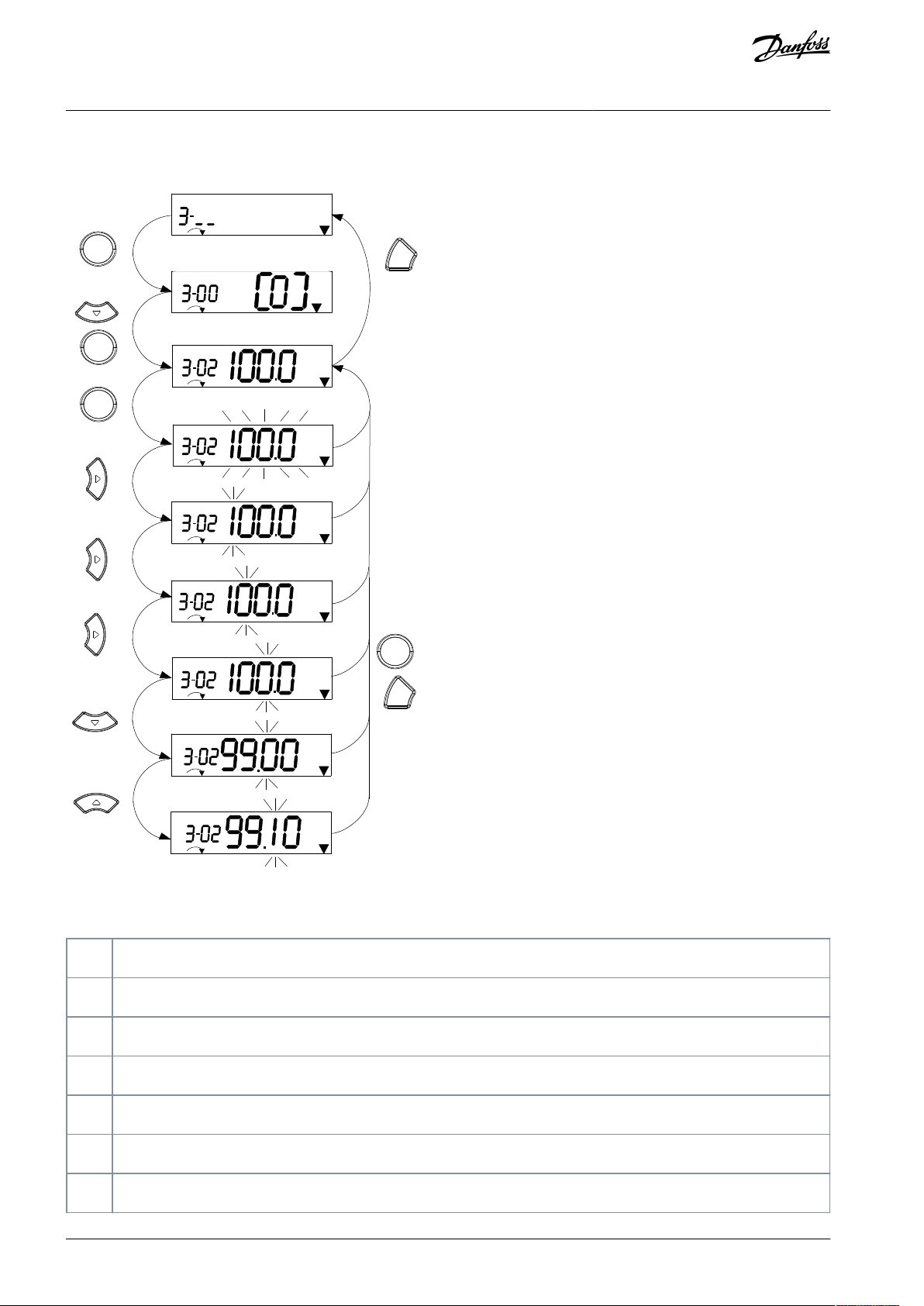
5.3.5.2 Continuous Parameters
Commissioning
Illustration 26: Main Menu Interactions - Continuous Parameters
Table 10: Changing Values in Continuous Parameters
AQ381425076031en-000101 / 130R122340 | Danfoss A/S © 2022.02

8
[▵]: Increases the parameter value.
9
[Back]: Cancel changes, return to 2.
[OK]: Accept changes, return to 2.
10
[▵][▿]: Select parameter within the group.
11
[Back]: Removes the value and shows the parameter group.
12
[▵][▿]: Select group.
e30bc447.11
Setup 1
Setup 1
Setup 1
1
2
3
4
5
6
OK
OK
Back
7
OK
Back
1
[OK]: The first parameter in the group is shown.
2
Press [OK] to start editing.
3
[▵][▿]: Change parameter value (flashing).
4
Press [Back] to cancel changes or [OK] to accept changes (return to screen 2).
5
[▵][▿]: Select a parameter within the group.
6
[Back]: Removes the value and shows the parameter group.
7
[▵][▿]: Select a group.
VLT® Midi Drive FC 280
Operating Guide
Commissioning
5.3.5.3 Enumerated Parameters
For enumerated parameters, the interaction is similar, but the parameter value is shown in brackets because of the digits limitation
(4 large digits) on the NLCP, and the enum can be greater than 99. When the enum value is greater than 99, the LCP can only show
the first part of the bracket.
Illustration 27: Main Menu Interactions - Enumerated Parameters
Table 11: Changing Values in Enumerated Parameters
AQ381425076031en-000101 / 130R1223 | 41Danfoss A/S © 2022.02

e30bc448.10
1
2
4
5
6
7
8
9
10
OK
Back
Back
Back
5 x
Setup 1
Setup 1
Setup 1
Setup 1
%
INDEX
%
INDEX
%
INDEX
Setup 1
INDEX
%
OK
OK
OK
1
[OK]: Shows parameter numbers and the value in the first index.
2
[OK]: Index can be selected.
3
[▵][▿]: Select index.
4
[OK]: Value can be edited.
5
[▵][▿]: Change parameter value (flashing).
6
[Back]: Cancels changes.
[OK]: Accepts changes.
7
[Back]: Cancels editing index, selects a new parameter.
8
[▵][▿]: Select parameter within the group.
9
[Back]: Removes parameter index value and shows the parameter group.
10
[▵][▿]: Select group.
VLT® Midi Drive FC 280
Operating Guide
5.3.5.4 Array Parameters
Commissioning
Illustration 28: Main Menu Interactions - Array Parameters
Table 12: Changing Values in Array Parameters
5.3.6 Graphical Local Control Panel
The GLCP is divided into 4 functional groups.
•
A. Display area.
•
B. Display menu keys.
•
C. Navigation keys and indicator lights (LEDs).
•
D. Operation keys and reset.
AQ381425076031en-000101 / 130R122342 | Danfoss A/S © 2022.02

e30bd598.10
Auto
On
Reset
Hand
On
Off
Status
Quick
Menu
Main
Menu
Alarm
Log
Back
Cancel
Info
OK
Status
1(1)
36.4 kW
Auto Remote Ramping
0.000
On
Alarm
Warn.
A
7.83 A
799 RPM
B
C
D
53.2 %
1
2
3
4
5
6
7
8
9
10
11
12
13
14
15
16
17
18
19 20 21
Display
Parameter number
Default setting
1
0-20
[1602] Reference [%]
2
0-21
[1614] Motor Current
3
0-22
[1610] Power [kW]
4
0-23
[1613] Frequency
5
0-24
[1502] kWh Counter
VLT® Midi Drive FC 280
Operating Guide
Commissioning
Illustration 29: Graphic Local Control Panel (GLCP)
A. Display area
The display area is activated when the drive receives power from the mains voltage, a DC bus terminal or a 24 V DC external supply.
The information shown on the LCP can be customized for user applications. Select options in the Quick Menu Q3-13 Display Settings.
Table 13: Legend to Section A
B. Display menu keys
Menu keys are used for menu access for parameter set-up, toggling through status display modes during normal operation, and
viewing fault log data.
AQ381425076031en-000101 / 130R1223 | 43Danfoss A/S © 2022.02
•
Number
Key
Function
6
Status
Shows operational information.
7
Quick Menu
Allows access to programming parameters for initial set-up instructions and many detailed application
instructions.
8
Main Menu
Allows access to all programming parameters.
9
Alarm Log
Shows a list of current warnings, the last 10 alarms, and the maintenance log.
Number
Key
Function
10
Back
Reverts to the previous step or list in the menu structure.
11
Cancel
Cancels the last change or command as long as the display mode has not changed.
12
Info
Press for a definition of the function being shown.
13
Navigation keys
To move between items in the menu, use the 4 navigation keys.
14OKPress to access parameter groups or to enable a selection.
Number
Indicator
Light
Function
15OnGreen
ON turns on when the drive receives power from the mains voltage, a DC bus terminal or a 24 V
DC external supply.
16
Warn
Yellow
When warning conditions are met, the yellow WARN LED turns on, and text appears in the display area identifying the problem.
17
Alarm
Red
A fault condition causes the red alarm LED to flash, and an alarm text is shown.
Number
Key
Function
18
Hand On
Starts the drive in hand-on mode.
An external stop signal by control input or serial communication overrides the local hand on.
19
Off
Stops the motor but does not remove power to the drive.
20
Auto On
Puts the system in remote operational mode.
VLT® Midi Drive FC 280
Operating Guide
Table 14: Legend to Section B
Commissioning
C. Navigation keys and indicator lights (LEDs)
Navigation keys are used for programming functions and moving the display cursor. The navigation keys also provide speed control
in local operation. There are also 3 drive status indicator lights in this area.
Table 15: Legend to Section C, Navigation Keys
Table 16: Legend to Section C, Indicator Lights (LEDs)
D. Operation keys and reset
Operation keys are at the bottom of the LCP.
Table 17: Legend to Section D
AQ381425076031en-000101 / 130R122344 | Danfoss A/S © 2022.02

•
Number
Key
Function
Responds to an external start command by control terminals or serial communication.
21
Reset
Resets the drive manually after a fault has been cleared.
VLT® Midi Drive FC 280
Operating Guide
Commissioning
N O T I C E
To adjust the display contrast, press [Status] and the [▵]/[▿] keys.
5.3.7 Parameter Settings
Establishing the correct programming for applications often requires setting functions in several related parameters.
Programming data is stored internally in the drive.
•
For back-up, upload data into the LCP memory.
•
To download data to another drive, connect the LCP to that unit and download the stored settings.
•
Restoring factory default settings does not change data stored in the LCP memory.
5.3.8 Changing Parameter Settings with GLCP
5.3.8.1 Introduction
Access and change parameter settings from the Quick Menu or from the Main Menu. The Quick Menu only gives access to a limited
number of parameters.
5.3.8.2 Changing Parameter Settings
Procedure
1.
Press [Quick Menu] or [Main Menu] on the GLCP.
2.
Press [▵] [▿] to browse through the parameter groups, press [OK] to select a parameter group.
3.
Press [▵] [▿] to browse through the parameters, press [OK] to select a parameter.
4.
Press [▵] [▿] to change the value of a parameter setting.
5.
Press [◃] [▹] to shift digit when a decimal parameter is in the editing state.
6.
Press [OK] to accept the change.
7.
Press either [Back] twice to enter Status, or press [Main Menu] once to enter the Main Menu.
5.3.8.3 View Changes
Quick Menu Q5 - Changes Made lists all parameters changed from default settings.
•
The list only shows parameters which have been changed in the current edit set-up.
•
Parameters which have been reset to default values are not listed.
•
The message Empty indicates that no parameters have been changed.
5.3.9 Backing-up/Downloading Parameters
Procedure
Press [Off] on GLCP or [Off Reset] on NLCP to stop the motor before uploading or downloading data.
1.
2.
Press [Main Menu] parameter 0-50 LCP Copy and press [OK].
3.
Select [1] All to LCP to upload data to the LCP, or select [2] All from LCP to download data from the LCP.
Press [OK]. A progress bar shows the uploading or downloading progress.
4.
Press [Hand On] or [Auto On] to return to normal operation.
5.
AQ381425076031en-000101 / 130R1223 | 45Danfoss A/S © 2022.02

VLT® Midi Drive FC 280
Operating Guide
Commissioning
5.3.10 Restoring Default Settings with LCP
5.3.10.1 Introduction
N O T I C E
BACK UP DATA TO LCP
Risk of losing programming, motor data, localization, and monitoring records by restoration of default settings.
To provide a back-up, upload data to the LCP before initialization.
-
Restoring the default parameter settings is done by initialization of the drive. Initialization is carried out via parameter 14-22 Opera-
tion Mode (recommended) or manually.
Recommended initialization via parameter 14-22 Operation Mode does not reset the following settings:
Operating hours.
•
Serial communication selections.
•
Fault log.
•
Alarm log.
•
Other monitoring functions.
•
•
Parameter 0-03 Regional Settings.
•
Parameter 1-06 Clockwise Direction.
Manual initialization erases all motor, programming, localization, monitoring data, and restores factory default settings. Manual initialization does not reset the following information:
•
Parameter 0-03 Regional Settings.
•
Parameter 1-06 Clockwise Direction.
•
Parameter 15-00 Operating hours.
•
Parameter 15-03 Power Up's.
•
Parameter 15-04 Over Temp's.
•
Parameter 15-05 Over Volt's.
5.3.10.2 Recommended Initialization
Procedure
1.
Select parameter 14-22 Operation Mode and press [OK].
2.
Select [2] Initialisation and press [OK].
Remove power to the unit and wait until the display turns off.
3.
Apply power to the unit. Default parameter settings are restored during start-up. This may take slightly longer than normal.
4.
5.
Alarm 80, Drive initialised to default value is shown.
Press [Reset] to return to operating mode.
6.
5.3.10.3 Manual Initialization
Procedure
Remove power to the unit and wait until the display turns off.
1.
Press and hold [Status], [Main Menu], and [OK] at the same time on the GLCP, or press [Menu] and [OK] at the same time on
2.
the NLCP while applying power to the unit (approximately 5 s or until a click is heard and the fan starts).
Factory default parameter settings are restored during start-up. This may take slightly longer than normal.
3.
5.4 Basic Programming
5.4.1 Asynchronous Motor Set-up
5.4.1.1 Setting Up Asynchronous Motor
Procedure
AQ381425076031en-000101 / 130R122346 | Danfoss A/S © 2022.02

VLT® Midi Drive FC 280
Operating Guide
1.
Enter the following motor data in the listed order. Find the information on the motor nameplate.
a.
Parameter 1-20 Motor Power.
b.
Parameter 1-22 Motor Voltage.
c.
Parameter 1-23 Motor Frequency.
d.
Parameter 1-24 Motor Current.
e.
Parameter 1-25 Motor Nominal Speed.
For optimum performance in VVC+ mode, extra motor data is required to set up the following parameters. The data is
2.
found in the motor datasheet (this data is typically not available on the motor nameplate).
a.
Parameter 1-30 Stator Resistance (Rs).
b.
Parameter 1-31 Rotor Resistance (Rr).
c.
Parameter 1-33 Stator Leakage Reactance (X1).
d.
Parameter 1-35 Main Reactance (Xh).
3.
Run a complete AMA using parameter 1-29 Automatic Motor Adaption (AMA) [1] Enable Complete AMA or enter the parameters manually.
Commissioning
5.4.1.2 Application-specific Adjustment When Running VVC+
VVC+ is the most robust control mode. In most situations, it provides optimum performance without further adjustments. Run a
complete AMA for best performance.
5.4.2 PM Motor Set-up in VVC+
5.4.2.1 Initial Programming Steps
Procedure
1.
Set parameter 1-10 Motor Construction to the following options to activate PM motor operation:
a.
[1] PM, non salient SPM
b.
[3] PM, salient IPM
2.
Select [0] Open Loop in parameter 1-00 Configuration Mode.
5.4.2.2 Programming Motor Data
N O T I C E
Encoder feedback is not supported for PM motors.
When the initial programming steps are completed, the PM motor-related parameters in parameter groups 1-2* Motor Data, 1-3*
Adv. Motor Data, and 1-4* Adv. Motor Data II are active.
The information is on the motor nameplate and in the motor datasheet.
Program the following parameters in the listed order.
Procedure
1.
Parameter 1-24 Motor Current.
2.
Parameter 1-26 Motor Cont. Rated Torque.
3.
Parameter 1-25 Motor Nominal Speed.
4.
Parameter 1-39 Motor Poles.
5.
Parameter 1-30 Stator Resistance (Rs).
Enter line-to-common stator winding resistance (Rs). If only line-to-line data is available, divide the line-to-line value by 2
to achieve the line-to-common (starpoint) value.
It is also possible to measure the value with an ohmmeter, which also takes the resistance of the cable into account. Divide the measured value by 2 and enter the result.
6.
Parameter 1-37 d-axis Inductance (Ld).
Enter line-to-common direct axis inductance of the PM motor. If only line-to-line data is available, divide the line-to-line
value by 2 to achieve the line-to-common (starpoint) value.
It is also possible to measure the value with an inductance meter, which also takes the inductance of the cable into account. Divide the measured value by 2 and enter the result.
AQ381425076031en-000101 / 130R1223 | 47Danfoss A/S © 2022.02

•
•
•
Application
Settings
Low inertia applications I
Load/IMo-
tor
<5
(1)
Increase the value for parameter 1-17 Voltage filter time const. by factor 5 to 10.
Reduce the value for parameter 1-14 Damping Gain.
Reduce the value (<100%) for parameter 1-66 Min. Current at Low Speed.
Medium inertia applications
50>I
Load/IMotor
>5
Keep calculated values.
High inertia applications I
Load/IMotor
> 50
Increase the values for parameter 1-14 Damping Gain, parameter 1-15 Low Speed Filter Time
Const., and parameter 1-16 High Speed Filter Time Const.
High load at low speed <30% (rated
speed)
Increase the value for parameter 1-17 Voltage filter time const. Increase the value for param-
eter 1-66 Min. Current at Low Speed (>100% for longer time can overheat the motor).
VLT® Midi Drive FC 280
Operating Guide
7.
Parameter 1-40 Back EMF at 1000 RPM.
Commissioning
Enter line-to-line back EMF of the PM motor at 1000 RPM mechanical speed (RMS value). Back EMF is the voltage generated by a PM motor when no drive is connected and the shaft is turned externally. Back EMF is normally specified for
nominal motor speed or for 1000 RPM measured between 2 lines. If the value is not available for a motor speed of 1000
RPM, calculate the correct value as follows:
For example, if back EMF at 1800 RPM is 320 V, the back EMF at 1000 RPM is:
Back EMF=(Voltage/ RPM)x1000=(320/1800)x1000=178
Program this value for parameter 1-40 Back EMF at 1000 RPM.
5.4.2.3 Testing Motor Operation
Procedure
1.
Start the motor at low speed (100–200 RPM). If the motor does not run, check installation, general programming, and motor data.
5.4.2.4 Parking
This function is the recommended option for applications where the motor is rotating at low speed, for example windmilling in fan
applications. Parameter 2-06 Parking Current and parameter 2-07 Parking Time are adjustable. Increase the factory setting of these
parameters for applications with high inertia.
Start the motor at nominal speed. If the application does not run well, check the VVC+ PM settings. Recommendations in different
applications are shown in
Table 18.
Table 18: Recommendations in Different Applications
1
I
=The inertia of load. I
Load
=The inertia of motor.
Motor
If the motor starts oscillating at a certain speed, increase parameter 1-14 Damping Gain. Increase the value in small steps.
Adjust the starting torque in parameter 1-66 Min. Current at Low Speed. 100% provides nominal torque as starting torque.
5.4.3 Automatic Motor Adaptation (AMA)
5.4.3.1 Introduction
It is highly recommended to run AMA because it measures the electrical characteristics of the motor to optimize compatibility between the drive and the motor in VVC+ mode.
The drive builds a mathematical model of the motor for regulating output motor current, thus enhancing motor performance.
•
•
Some motors are unable to run the complete version of the test. In that case, select [2] Enable reduced AMA in parameter 1-29
Automatic Motor Adaption (AMA).
•
If warnings or alarms occur, see chapter List of Warnings and Alarms.
Run this procedure on a cold motor for best results.
•
AQ381425076031en-000101 / 130R122348 | Danfoss A/S © 2022.02

VLT® Midi Drive FC 280
Operating Guide
N O T I C E
The AMA function does not cause the motor to run, and it does not harm the motor.
5.4.3.2 Running AMA via LCP
Procedure
1.
By default parameter setting, connect terminals 13 and 27 before running AMA.
2.
Enter the Main Menu.
3.
Go to parameter group 1-** Load and Motor.
4.
Press [OK].
5.
Set motor parameters using nameplate data for parameter group 1-2* Motor Data.
6.
Set motor cable length in parameter 1-42 Motor Cable Length.
7.
Go to parameter 1-29 Automatic Motor Adaptation (AMA).
8.
Press [OK].
9.
Select [1] Enable complete AMA.
Press [OK].
10.
The test runs automatically and indicates when it is complete.
11.
Depending on the power size, the AMA takes 3–10 minutes to complete.
12.
5.5 Checking Motor Rotation
Check the motor rotation before running the drive.
Procedure
1.
Press [Hand On].
2.
Press [▵] for positive speed reference.
3.
Check that the speed shown is positive.
4.
Verify that the wiring between the drive and the motor is correct.
5.
Verify that the motor running direction matches the setting in parameter 1-06 Clockwise Direction.
a.
When parameter 1-06 Clockwise Direction is set to [0] Normal (default clockwise), verify that the motor turns clockwise and the LCP direction arrow is clockwise.
b.
When parameter 1-06 Clockwise Direction is set to [1] Inverse (counterclockwise), verify that the motor turns counterclockwise and the LCP direction arrow is counterclockwise.
Commissioning
5.6 Checking Encoder Rotation
Only check encoder rotation if encoder feedback is used.
Procedure
1.
Select [0] Open Loop in parameter 1-00 Configuration Mode.
2.
Select [1] 24 V encoder in parameter 7-00 Speed PID Feedback Source.
Press [Hand On].
3.
4.
Press [▵] for positive speed reference (parameter 1-06 Clockwise Direction at [0] Normal).
5.
Check in parameter 16-57 Feedback [RPM] that the feedback is positive.
N O T I C E
NEGATIVE FEEDBACK
If the feedback is negative, the encoder connection is wrong.
Use parameter 5-71 Term 32/33 Encoder Direction to inverse the direction, or reverse the encoder cables.
-
5.7 Testing Local-control
Procedure
1.
Press [Hand On] to provide a local start command to the drive.
2.
Accelerate the drive by pressing [▵] to full speed. Moving the cursor left of the decimal point provides quicker input
changes.
3.
Note any acceleration problems.
AQ381425076031en-000101 / 130R1223 | 49Danfoss A/S © 2022.02

Description
Ordering number
VLT® Memory Module MCM 102
132B0359
VLT® Memory Module MCM 103
132B0466
Parameter 31-40 Memory Module
Function
Description
[0] Disabled
Downloading or uploading data function is disabled.
*[1] Only Allow Download
Only allow downloading data from the memory module to the drive. This is the default
setting of parameter 31-40 Memory Module Function.
[2] Only Allow Upload
Only allow uploading data from the drive to the memory module.
[3] Allow Both Download and Upload
If this option is selected, the drive downloads data from memory module first, and then
uploads data from the drive to the memory module.
VLT® Midi Drive FC 280
Operating Guide
4.
Press [Off]. Note any deceleration problems.
Commissioning
5.8 System Start-up
The procedure in this section requires user-wiring and application programming to be completed. The following procedure is recommended after application set-up is completed.
Procedure
1.
Press [Auto On].
2.
Apply an external run command.
3.
Adjust the speed reference throughout the speed range.
4.
Remove the external run command.
5.
Check the sound and vibration levels of the motor to ensure that the system is working as intended.
If warnings or alarms occur, see 8.2 Warning and Alarm Types for resetting the drive after a trip.
5.9 Memory Module
5.9.1 Memory Module Overview
The VLT® Memory Module MCM is a small memory device containing data such as:
•
Firmware for the drive (not including the firmware for communication on the control card).
•
PUD file.
•
SIVP file.
•
Parameter file.
The VLT® Memory Module MCM is an accessory. The drive comes without the memory module installed from the factory. A new
memory module can be ordered using the following ordering numbers.
Table 19: Ordering Number
Each memory module has a unique serial number which cannot be modified.
N O T I C E
The VLT® Memory Module MCM can be used on the drive together with firmware 1.5 and above.
N O T I C E
The VLT® Memory Module MCM does not support copying functional safety related firmware and parameters.
Select correct options for parameter 31-40 Memory Module Function before configuring with the memory module.
Table 20: Description of Parameter 31-40 Memory Module Function
AQ381425076031en-000101 / 130R122350 | Danfoss A/S © 2022.02

VLT® Midi Drive FC 280
Operating Guide
Commissioning
N O T I C E
AVOID UNINTENTIONAL OVERWRITING
The default setting of parameter 31-40 Memory Module Function is [1] Only Allow Download. If there is any update, such as firmware updated by MCT 10 using OSS file, parameter updated by LCP or bus, parameters reset via parameter 14-22 Operation Mode,
or 3-finger-reset of the drive, the updated data will be lost after a new power cycle, because the drive downloads data from the
memory module again.
After the data has been downloaded from the memory module to the drive, select [0] Disabled or [2] Only Allow Upload in
-
parameter 31-40 Memory Module Function before the new power cycle.
5.9.2 Synchronizing Drive Data to a New Memory Module (Create Drive Backup)
N O T I C E
To avoid unintentional overwriting of the data in the memory module, consider to adjust the settings for parameter 31-40 Memory Module Function before next power cycle according to different operating purpose.
Procedure
1.
Plug a new empty memory module in the drive.
2.
Select [2] Only Allow Upload or [3] Allow Both Download and Upload in parameter 31-40 Memory Module Function.
3.
Power up the drive.
4.
Wait until the synchronization is complete, refer to 5.9.8 Transfer Performance and Indications to check the transfer indications on the drive.
5.9.3 Copying Data to Another Drive
N O T I C E
To avoid unintentional overwriting of the data in the memory module, consider to adjust the settings for parameter 31-40 Memory Module Function before next power cycle according to different operating purpose.
Procedure
1.
Make sure that the required data is uploaded to the memory module, refer to 5.9.2 Synchronizing Drive Data to a New
Memory Module (Create Drive Backup).
2.
Unplug the memory module and plug into a new drive.
3.
Make sure that [1] Only Allow Download or [3] Allow Both Download and Upload is selected in parameter 31-40 Memory Module Function on the new drive.
4.
Power up the new drive.
5.
Wait until the download is complete and the data is transferred, refer to 5.9.8 Transfer Performance and Indications to
check the transfer indications on the drive.
5.9.4 Copying Data to Multiple Drives
If multiple drives are of same voltage/power, the information of 1 drive can be transferred to the others via 1 memory module.
N O T I C E
The data can also be downloaded to the memory module from a PC via the VLT® Memory Module Programmer.
N O T I C E
In any of the drives, if an empty memory module is plugged in for backing up data, adjust the settings for parameter 31-40 Memory Module Function to [2] Only Allow Upload or [3] Allow Both Download and Upload before next power cycle.
Procedure
AQ381425076031en-000101 / 130R1223 | 51Danfoss A/S © 2022.02

•
•
Data file
Time
Firmware file
It takes around 2 minutes for uploading data from the drive to the memory module.
It takes around 6 minutes for downloading data from the memory module to the drive.
SIVP file
Around 10 s.
Parameter file
(1)
Around 5 s.
VLT® Midi Drive FC 280
Operating Guide
1.
Follow the steps in 5.9.2 Synchronizing Drive Data to a New Memory Module (Create Drive Backup) to upload the data from
1 drive to a memory module.
2.
To avoid unintentional uploading of data to the master memory module, make sure that [1] Only Allow Download is selected in parameter 31-40 Memory Module Function on the other drives.
Unplug the memory module and plug into a new drive.
3.
Power up the new drive.
4.
Wait until the download is complete and the data is transferred, refer to
5.
check the transfer indications on the drive.
6.
Repeat steps 3–5 for the next drive.
5.9.8 Transfer Performance and Indications to
Commissioning
5.9.5 Transferring the Firmware Information
If 2 drives are of same voltage and power size, the firmware information can be transferred from 1 drive to another.
N O T I C E
The firmware information can also be downloaded to the memory module from a PC via the VLT® Memory Module Programmer.
Procedure
1.
Follow the steps in 5.9.2 Synchronizing Drive Data to a New Memory Module (Create Drive Backup) to upload the firmware
information from 1 drive to a memory module.
2.
Follow the steps in 5.9.3 Copying Data to Another Drive to transfer the firmware information to another drive of same voltage and power size.
5.9.6 Backing Up Parameter Changes to Memory Module
Procedure
1.
Plug a new empty memory module in the drive.
2.
Select [2] Only Allow Upload or [3] Allow Both Download and Upload in parameter 31-40 Memory Module Function.
3.
Power up the drive.
4.
Wait until the synchronization is complete. Refer to 5.9.8 Transfer Performance and Indications to check the transfer indications on the drive.
5.
Any change to parameter settings is automatically synchronized to the memory module.
5.9.7 Erasing Data
The memory module can be erased via setting parameter 31-43 Erase_MM without a new power cycle.
Procedure
1.
Make sure that the memory module is mounted in the drive.
2.
Select [1] Erase MM in parameter 31-43 Erase_MM.
3.
All files in the memory module are erased.
4.
Parameter 31-43 Erase_MM setting returns to [0] No function.
5.9.8 Transfer Performance and Indications
The time for transferring different data between the drive and the memory module is different, refer to the following table.
Table 21: Transfer Performance
1
If a parameter is changed in the drive, to upload the updated parameter, wait at least 5 s before power-down.
AQ381425076031en-000101 / 130R122352 | Danfoss A/S © 2022.02

Data file
Indications
GLCP
NLCP
On LED
(1)
Firmware file
“Synchronizing with Memory Module.” is shown
during transferring.
No text indication.
The LED flashes slowly during the transfer.
SIVP file
Parameter file
No text indication.
The LED does not flash.
VLT® Midi Drive FC 280
Operating Guide
Table 22: Transfer Indications
1
The On LED is lit on the LCP. Refer to 5.3.2 Numerical Local Control Panel and 5.3.6 Graphical Local Control Panel for the On LED’s position and
functions.
Commissioning
AQ381425076031en-000101 / 130R1223 | 53Danfoss A/S © 2022.02

VLT® Midi Drive FC 280
Operating Guide
Safety Functions
6 Safety Functions
6.1 Introduction
The drive is integrated with Ethernet safety functions according to application needs.
According to EN IEC 61800-5-2, the following 2 safety functions are available within the drive:
•
Safe Torque Off (STO): no torque is being fed to the motor can generate a rotation. (Stop category 0 according to EN IEC
60204-1.)
•
Safe Stop 1 time controlled (SS1-t): motor decelerates within a specified deceleration time. Safe Torque Off is activated at the
end of a deceleration time. (Stop category 1 according to EN IEC 60204-1).
Both of the safety functions fulfill SIL3/SIL CL 3 (according to IEC 61508/61800-5-2/62061) and Category 3/PL e (according to ISO
13849-1) and can be triggered via:
•
Digital I/O (terminal 37 and 38, referred at SGND terminal 39).
•
Safety fieldbus.
The following safety fieldbuses are supported by the drive:
•
PROFIsafe communication over PROFINET.
•
FSoE communication over EtherCAT (subsequent version).
Communication over PROFIsafe is implemented according to the PROFIdrive on PROFIsafe amendment.
To view or download the certificate, search TÜV Functional safety FC 280 on www.danfoss.com.
W A R N I N G
DESIGN OF SAFETY SYSTEMS
The designing of safety-related systems requires special knowledge and skills.
Only qualified persons are allowed to install and set up an advanced safety option board.
-
W A R N I N G
USE OF SAFETY FUNCTIONS
The use of safety functions provided by the drive does not in itself ensure safety.
To make sure that the commissioned system is safe, make an overall risk assessment.
-
Safety devices must be correctly incorporated into the entire system. The entire system must be designed in compliance
-
with all relevant standards within the field of industry. (Standards such as EN 12100 Part 1, Part 2, and ISO 14121-1 provide
methods for designing safe machinery and making a risk assessment.)
N O T I C E
The information in this manual provides guidance on the use of the safety functions that FC 280 provides. This information is in
compliance with accepted practice and regulations at the time of writing. However, the product/system designer is responsible
for making sure that the system is safe and in compliance with relevant regulations.
N O T I C E
The drive must be used in an environment where no conductive dust or contaminants are present.
To ensure proper protection against contamination, use the drive in at least an IP54 enclosure.
-
AQ381425076031en-000101 / 130R122354 | Danfoss A/S © 2022.02

//
//
M
//
//
e30bu897.10
Safe option B
T38
T37
Option
A
Control unit
Power unit
Black channel
Logic A
Logic B
Cross check
PELV HV
UDC+
Vdd
PWM
PWM
Low-side
gate drive
High-side
gate drive
Diagnosis
&
control
VLT® Midi Drive FC 280
Operating Guide
6.2 System Overview
6.2.1 Safety Function Architecture
The control unit of the drive consists of:
•
Control card.
•
Built-in option A (supports PROFINET/POWERLINK/Ethernet IP/EtherCAT fieldbus).
•
Built-in safety option B (provides safety functions).
Safety Functions
Illustration 30: Safety Function Architecture
The safety loop within the drive is dual-channel based structure. There is one dual-channel safety digital input:
•
Terminal 37, safe input channel a.
•
Terminal 38, safe input channel b.
•
Terminal 39, dedicated GND for terminal 37 and 38.
The safety digital input can be configured as STO, SS1-t, or disabled (default) via setting parameters. If disabled, the drive does not
react with any signal on terminal 37 or 38. Terminal 37, 38, and 39 are isolated with other inputs of the drive.
There is an RJ45 port for safety fieldbus communication. The safety communication protocol can be enabled or disabled (default)
via setting parameters. If disabled, the drive ignores any safety function via fieldbus.
N O T I C E
Safety digital input and safety fieldbus protocol are all DISABLED as factory default.
-
Safety components are already mounted within the drive. Disassembling any part of the drive is not allowed.
If both safety digital input and safety fieldbus are enabled, STO or SS1-t can be triggered via both sources. STO has the highest
priority. SS1-t can be interrupted by STO from any trigger source.
Configure the needed safety functions correctly with MCT-10 tool before use.
N O T I C E
AQ381425076031en-000101 / 130R1223 | 55Danfoss A/S © 2022.02

FC 280
Safety fieldbus
Disabled*
(1)
Enabled
Safety digital input
Disabled*
(1)
None
STO
(2)
and SS1-t
(2)
STO
STO
(3)
STO
(4)
and SS1-t
(2)
SS1-t
SS1-t
(3)
SS1-t
(4)
and STO
(2)
VLT® Midi Drive FC 280
Operating Guide
Table 23: Safety Functions Combination in Drive
1
* means default value.
2
Via fieldbus only.
3
Via digital input only.
4
Via both trigger sources.
Safety Functions
6.2.2 Safe State
The safe state of the drive is STO achieved or power off.
6.2.3 Internal and External Fault
Internal fault
The diagnosis mechanism of the drive detects the internal fault inside the drive.
Normally, an internal fault is caused by:
EMI.
•
Random failure of components.
•
Harsh environment condition.
•
Other systematic errors.
•
When an internal fault is detected, the drive reports an alarm and switches to the safe state. To reset the drive, clear the alarm manually or recycle the power supply.
External fault
External fault is the fault caused by invalid external input which includes:
Discrepancy on safety digital input.
•
Safety fieldbus communication errors.
•
Fieldbus master, for example a PLC, forces the drive into safe state.
•
6.2.4 Fault Reaction
When an internal fault is detected, the fault reaction is STO. When an external fault happens, the fault reaction can be defined via
setting parameter 42-30 External Failure Reaction to STO or SS1-t.
Assess the risk before using SS1-t as external failure reaction.
6.2.5 Recovery from Safe State
6.2.5.1 Recovery from Safe Function Triggered Normally
Restart behavior of safe digital input
C A U T I O N
AQ381425076031en-000101 / 130R122356 | Danfoss A/S © 2022.02

Safety event
index
Safety event
User action required when safe
fieldbus is disabled
User action required when
safe fieldbus is enabled
1
Customization aborted
Manual reset
–2Customization completed
Manual reset
–3General reset
Manual reset
–4Internal failures
Power cycle
Power cycle
5
External failures
Manual reset
Manual reset
6
SO initialized (power up without failure)
Manual reset
–7Safe function pending
Manual reset
Manual reset
VLT® Midi Drive FC 280
Operating Guide
When safe function is achieved by the safe digital input (terminal 37 and 38), the reset action to restart the motor depends on the
configuration of restart behavior. Parameter 42-24 Restart Behavior determines whether the drive restarts automatically or waits for a
manual reset after the safety function is achieved.
•
Automatic reset: when the safety function is achieved, the safety option can run again when the condition that triggered the
safety function ceases. This behavior is only valid for the digital input where this reset behavior is defined. For example, if there
is an external fault, a manual reset from the reset source is required regardless of the setting in parameter 42-24 Restart Behavior.
Manual reset: when the safety function is achieved, the drive requires a reset from a reset source before it can run again. The
•
reset source could be the following (refer to
Source and its options):
-
The Reset key on the LCP.
A specified non-safe digital input.
-
The reset command via fieldbus other than PROFIsafe (for example RS485, PROFINET).
-
Restart behavior of safe fieldbus
6.12 Safety-related Parameters for more information on parameter 42-31 Reset
Safety Functions
N O T I C E
Make sure that the surrounding environment is safe before recovering from safe state.
The drive resets automatically when inactive command received from the host device via safety fieldbus protocol.
6.2.5.2 Recovery from Safety Events
Table 24: Recovery from Safety Events
6.3 Safety Functions
6.3.1 Safe Torque Off (STO)
Safe Torque Off (STO) prevents the drive from generating the energy that is required to rotate the motor, thus ensures the safety of
the system in emergency situations.
The STO function in the drive is controlled via redundant safety digital input (terminals 37 and 38) or/and safety fieldbus. When STO
is activated, the power supply on the high side and low side of the IGBT gate driving circuits is cut off. The following illustration
shows the STO architecture.
AQ381425076031en-000101 / 130R1223 | 57Danfoss A/S © 2022.02

f
e30bc318.11
t
1
2
A
A
Actual frequency
1
Activation of Safe Torque Off
2
Motor standstill
Terminal 37
Terminal 38
Torque
Warning/alarm
High
(1)
High
Yes
(2)
None
Low
(3)
LowNoW68
Low
HighNoW252
High
LowNoW252
VLT® Midi Drive FC 280
Operating Guide
Safety Functions
Illustration 31: Safe Torque Off
6.3.1.1 STO Triggered by DI
To enable safe DI as STO input, set parameter 42-20 Safe Function as [0] STO. The following table shows STO statuses based on
whether terminals 37 and 38 are energized.
Table 25: STO via DI
1
Voltage range is 24 V±15%, with terminal 39 as reference.
2
Torque is present only when the drive is running.
3
Open circuit or the voltage is within the range of 0 V ±1.5 V, with terminal 39 as reference.
6.3.1.2 STO Triggered by Fieldbus
To enable safety fieldbus protocol, set parameter 42-60 Telegram Selection to [1] PROFIsafe Std. Tel. 30. STO control command is sent
from the upper device continuously and periodically. The command includes:
STO inactive
•
STO active
•
AQ381425076031en-000101 / 130R122358 | Danfoss A/S © 2022.02

STO command
Torque
Warning/alarm
Inactive
Yes
(1)
None
Active
No
W68
VLT® Midi Drive FC 280
Operating Guide
Table 26: STO via Fieldbus
1
Torque is present only when the drive is running.
Safety Functions
6.3.1.3 Exit STO
The trigger sources of STO, safe DI and fieldbus, are independent if they are both enabled. To exit STO state, all of the trigger sources should be turned to inactive:
•
STO inactive command received on fieldbus.
•
Terminal 37 and 38 are High.
6.3.1.4 Restart Behavior
Even though the drive has exited STO state, the restart behavior of the motor has 2 modes depending on the setting of parameter
42–24 Restart Behavior:
•
If parameter 42–24 Restart Behavior is set to [1] Automatic, the motor can run again just after an On command is received.
•
If parameter 42–24 Restart Behavior is set to [0] Manual, the drive needs a Reset action for acknowledgement, and then the motor
can run again after an On command is received.
W A R N I N G
For manual restart mode, although the motor cannot run before a Reset action after STO state has exited, the motor is no longer
safe! Only safe DI and/or safe fieldbus commands are trustable for the remaining safe state.
6.3.2 Safe Stop 1 Time Controlled (SS1-t)
For SS1-t function, the drive decelerates to 0 speed within a defined deceleration time. Meanwhile, the safety components of the
drive count down the deceleration time and activate STO after the timer expires.
Features of the safety function
•
The safety function SS1-t fulfills Safe Stop 1 time controlled in accordance with EN/IEC 61800-5-2, and also corresponds to Stop
category 1 according to EN/IEC 60204-1.
•
The drive initiates the motor deceleration and performs STO function after an application-specific time delay.
•
The motor becomes torque-free and removes hazardous movements.
STO is activated immediately when the configured stop delay expires, regardless of speed.
AQ381425076031en-000101 / 130R1223 | 59Danfoss A/S © 2022.02

e30bc321.11
1
2
t
f
3
4
A
A
Actual frequency
1
Activation of SS1-t
2
Activation of Safe Torque Off
3
Parameter 42-42 Delay Time
4
Parameter 42-43 Delta T
VLT® Midi Drive FC 280
Operating Guide
Safety Functions
Illustration 32: Safe Stop 1 Time Controlled
SS1-t function activates a braking ramp defined from a selected time delay in parameter 42-42 Delay Time, which means the braking
ramp is linear. Select the value of parameter 42-43 Delta T (the percentage of delay time), which is a reasonable tolerance before the
SS1-t time expires.
N O T I C E
For SS1-t, ramping down the motor is performed by non-safety components, so it may fail undetected. Therefore, SS1-t cannot be
applied if this failure can cause a dangerous situation in the final application.
N O T I C E
The SS1-t function does not monitor the reality of motor's stopping. If any drive's fault occurs before SS1-t time expired, the drive
coasts immediately regardless of the motor speed.
Assess the suitability of SS1-t for end application.
-
W A R N I N G
Using SS1-t may result in the motor still spinning when the Safe Torque Off is activated. The risk analysis for the machine must
indicate that this behavior can be tolerated. An interlock may be required.
The parameter 42-43 Delta T only provides a time margin with hope of the drive could stop before STO is activated. Too much of
Delta T can bring a steep ramp down curves, which may cause overcurrent and coast the motor.
N O T I C E
AQ381425076031en-000101 / 130R122360 | Danfoss A/S © 2022.02

Previous status
Terminal 37
Terminal 38
Status
LCP display
Inactive
High
(1)
High
Inactive
None
High→Low
(2)
High→Low
Timer start
SS1-t
(3)
High→Low
High
Timer start
W252
High
High→Low
Timer start
W252
Timing
High
High
Timing
(4)
SS1-t
Timer stop & reset
(5)
None
Timing
Low
X
Timing
SS1-t
X
Low
Timer expired
XXSTO
W68
Previous status
SS1-t command
(1)
Status
LCP display
Inactive
Inactive
Inactive
None
Inactive→active
Timer start
SS1-t
(2)
Timing
Active
Timing
Inactive
Timer stop & reset
None
Timer expired
Active
STO
W68
Inactive
Inactive
None
VLT® Midi Drive FC 280
Operating Guide
Safety Functions
6.3.2.1 SS1-t Triggered by DI
To enable safe DI as SS1-t input, set parameter 42-20 Safe Function as [9] SS1-t. The following table shows SS1-t statuses based on
whether terminals 37 and 38 are energized.
Table 27: SS1-t via DI
1
Voltage range is 24 V±15%, with terminal 39 as reference.
2
Open circuit or the voltage within the range of 0 V±1.5 V, with terminal 39 as reference.
3
When setting parameter 0-2* LCP Display=[4285].
4
Parameter 42-24 Restart Behavior=[0] Manual.
5
Parameter 42-24 Restart Behavior=[1] Automatic, and no SS1-t request on fieldbus (inactive command or disabled).
6.3.2.2 SS1-t Triggered by Fieldbus
To enable safety fieldbus protocol, set parameter 42-60 Telegram Selection to [1] PROFIsafe Std. Tel. 30. SS1-t control command is sent
from the upper device continuously and periodically. The command includes:
SS1-t inactive
•
SS1-t active
•
Table 28: SS1-t via Fieldbus
1
2
See the table in
When setting parameter 0-2* LCP Display=[4285].
6.5.2.5.1 PROFIsafe Control Word.
AQ381425076031en-000101 / 130R1223 | 61Danfoss A/S © 2022.02

VLT® Midi Drive FC 280
Operating Guide
Safety Functions
6.3.2.3 SS1-t Timer Start
If one of the following events is detected, SS1-t timer starts immediately:
•
Terminal 37 becomes low.
•
Terminal 38 becomes low.
•
SS1-t active command received on fieldbus.
6.3.2.4 SS1-t Timing Quit
When SS1-t timer starts and does not expire, the SS1-t timer can be paused and reset when all of the following conditions are met:
•
When parameter 42-24 Restart Behavior is set to [1] Automatic, terminal 37 and terminal 38 are both high.
•
SS1-t inactive command received on fieldbus.
6.3.2.5 Safe State of SS1-t
The safe state of SS1-t is STO triggered before timer expires. If any internal fault is detected or external fault happens, the drive
triggers STO at any time.
N O T I C E
Assess the risk of STO interrupting SS1-t.
6.3.2.6 Timing Precision
The timing precision is:
Lowerlimit = N ×(1 − 0 . 1%)
Upperlimit = (N + 0.05) × (1 + 0. 1%)
N is the set time (set in parameter 42-42 Delay Time), and the unit is seconds.
6.4 Safety Digital Input
6.4.1 Valid Voltage
•
The valid voltage range of terminal 39 should be 0 V, PELV.
•
The valid voltage range of terminal 37 and 38 should be 0–24 V, PELV, refer to terminal 39.
•
If the voltage on terminal 37 or 38 is over 30 V, the drive enters protection mode and triggers STO.
•
If the voltage on terminal 37 or 38 is over 60 V, the circuitry of the drive will be damaged.
6.4.2 Debouncing
Some devices, for example safety PLC, generates a test pattern on its output for stuck checking. These test patterns can interrupt
the drive. The drive can ignore these test patterns on terminal 37 and 38 if they stay at low level (≤1.8 V) for no longer than 5 ms.
N O T I C E
To activate STO (or SS1-t) effectively and stably, keep the 2 channels both at low level for at least 1 s.
AQ381425076031en-000101 / 130R122362 | Danfoss A/S © 2022.02

Time
5 ms max.
Debounce time
Time
STO valid
STO invalid
Voltage
T37/38
Test pulse
STO demanded
STO request
state
e30be587.12
t
T37
T38
Input
signal
Discrepancy time
e30bu898.10
VLT® Midi Drive FC 280
Operating Guide
Illustration 33: Debouncing
Safety Functions
6.4.3 Discrepancy Tolerance
The input signals at the 2 terminals may not always be synchronous. If the discrepancy between the 2 signals is longer than 0.5 s,
the STO fault warning (W252) occurs.
Illustration 34: Discrepancy Time
N O T I C E
The discrepancy time does not extend the safety function’s response time. The drive activates its safety function as soon as the
earlier valid signal arrives.
6.5 Safety Fieldbus
6.5.1 PROFIsafe
PROFIsafe is an additional safety protocol on top of a standard transmission system (PROFINET/PROFIBUS). PROFIsafe uses several
technologies to ensure the validity and status of the fieldbus communication, making it reliable to use with safety devices.
These measures include:
•
Consecutive numbering.
•
Watchdog time monitoring with acknowledgement.
•
Codename per communication relationship.
•
Cyclic redundancy check for data integrity.
Communication over the non-safe transmission systems is called the "black channel".
AQ381425076031en-000101 / 130R1223 | 63Danfoss A/S © 2022.02

Standard data
Safe data
PROFisafe layer
PROFisafe layer
Safe data Standard data
Standard bus protocol
Standard bus protocol
PROFINET IO
e30bu892.10
e30bu893.10
S S S
S
S S
F-I/O data
Maximum 13 octets
1 octet
3 or 4 octets
1)
CRC2
Status byte/
control byte
1) PROFIsafe V2.4 corresponds to 3 octets, and PROFIsafe V2.6 corresponds to 4 octets.
Bit
Signal
Description
0
iPar_OK
Not used
1
Device_Fault
Fault in F-device
2
CE_CRC
Communication fault: CRC
3
WD_timeout
Communication fault: watchdog timeout
VLT® Midi Drive FC 280
Operating Guide
Illustration 35: PROFIsafe Communication
Safety Functions
6.5.2 PROFIsafe System
The drive can communicate with safety PLC via PROFINET. The exchanged data includes safety-related data and non-safe process
data. For safety-related data, it goes through PROFIsafe frame and matches PROFIdrive format.
The drive supports PROFIsafe V2.4 and V2.6. V2.6 is forward compatible with V2.4. To provide maximum flexibility and convenience,
the GSD file contains 4 modules. Select 1 of the following modules according to the requirement to set up communication between
the PLC and drive.
•
PROFIsafe_1: PROFIsafe V2.4, 3 octets CRC checksum, F_iPar_CRC checking is disabled.
•
PROFIsafe_2: PROFIsafe V2.4, 3 octets CRC checksum, F_iPar_CRC checking is enabled.
•
PROFIsafe_1: PROFIsafe V2.6, 4 octets CRC checksum, F_iPar_CRC checking is disabled.
•
PROFIsafe_2: PROFIsafe V2.6, 4 octets CRC checksum, F_iPar_CRC checking is enabled.
6.5.2.1 The PROFIsafe Frame
The PROFIsafe frame, which is exchanged between the safety PLC (F-host) and the safety follower (F-device), includes:
•
Safety I/O data (F-I/O), which is used to control the drive safety process.
•
A status/control byte, which is used for the PROFIsafe communication.
•
A CRC signature, which ensures the validity of the frame.
Illustration 36: Structure of the PROFIsafe Frame (S=Standard Frame)
To indicate, monitor, and set the safety status of the F-device, see the status and control bytes descriptions in the following tables.
For more details, refer to PROFIsafe – Profile for Safety Technology on PROFIBUS DP and PROFINET IO Technical Specification.
Table 29: PROFIsafe Status Byte Description
AQ381425076031en-000101 / 130R122364 | Danfoss A/S © 2022.02

Bit
Signal
Description
4
FV_activated
Fail-safe values (FV) activated
5
Toggle_d
Toggle Bit (F-device)
6
Cons_nr_R
Consecutive number has been reset
7–Reserved
Bit
Signal
Description
0
iPar_EN
Not used
1
OA_Req
Operator acknowledgement
2
R_cons_nr
Reset consecutive number
3–Reserved
4
Activate_FV
Fail-safe values (FV) to be activated
5
Toggle_h
Toggle Bit (F-host)
6–Reserved
7–Reserved
Value
Description
F source address
PROFIsafe address of PLC.
F destination address
The value must be the same as the F destination address on FC 280.
F WD Time
The value must be the same as the F WD time on FC 280.
F iPar CRC
The value must be the same as the final CRC of the parameter file on FC 280. The value can be seen
in MCT-10 after the verification of the parameter file is completed, on the control panel of the drive
or in the commissioning report printed from MCT-10.
Safety telegram & F-I/O
data of the safety telegram
The value must be the same as the safety telegram in FC 280. F-I/O data must be mapped as described in the tables in 6.5.2.5.1 PROFIsafe Control Word and 6.5.2.5.2 PROFIsafe Status Word.
VLT® Midi Drive FC 280
Operating Guide
Table 30: PROFIsafe Control Byte Description
Safety Functions
6.5.2.2 Parameterization for PROFIsafe
When using the PROFIsafe, the protocol requires specific safety parameters (F-parameters) to be sent from F-host to F-device. These
parameter values must be set to the drive via the MCT-10 safety tool and to F-host via its configuration tool. During start-up, the
values on the F-host are transmitted to the drive, and the drive checks the values against the values on the drive. The values configured to F-host and F-device must be the same for the safety communication to start.
The safety layer starts whenever the communication channel (PROFINET) is communicating cyclically. An unsuccessful initialization
of the PROFIsafe protocol does not have an effect on the PROFINET cyclic communication. The PROFINET cyclic communication can
be used to read diagnostic information if the PROFIsafe parameterization fails.
Table 31: Settings in the Safety PLC
The following PROFIsafe-related parameters cannot be edited in FC 280. They must have the same value in the safety PLC communication to the gateway chip in FC 280 over PROFIsafe. The values in the following table are defined in the fieldbus GSD description
file, which is provided for the gateway chip in FC 280 by Danfoss, and must not be modified.
N O T I C E
FC 280 has Type 1 of F-Address-Check, it means only F_DestAdd is checked by the drive.
AQ381425076031en-000101 / 130R1223 | 65Danfoss A/S © 2022.02

Parameter
Value
Unit
Description
F check iPar
0 = NoCheck
Manufacturer-specific iPar check.
F CRC length
0 = 3 or 4 bytes CRC
(1)
CRC2 signature length.
F block ID
1 = F iPar CRC within F parameter block
Parameter block type identification.
F Par version
1 = V2 Mode
Version no. of F parameters.
F SIL
8 = SIL3
Employed SIL level of F-device.
e30bu894.10
F WD Time (minimum)
DAT
Bus BusHAT
Symbol
Name
Description
DAT
Device Acknowledgment Time
70 ms for the complete AC drive system.
HAT
Host Acknowledgment Time
Application-specific.
BT
Bus Cycle Time
The bus cycle time.
VLT® Midi Drive FC 280
Operating Guide
Safety Functions
N O T I C E
The correctness of drive’s iParameter must be ensured by user via commissioning test.
Table 32: Non-editable F-parameters
1
It depends on PROFIsafe version: V2.4, 3 bytes CRC; V2.6, 4 bytes CRC.
6.5.2.3 PROFIsafe Watchdog Time
Use the F-parameter watchdog time (F WD time) to determine a watchdog time for the communication between F-host and F-device.
The minimum watchdog time has 4 parts:
DAT = Device Acknowledgment Time. The F-device receives a frame, processes it, and prepares a new frame to send.
•
Bus = the transfer time of the frame from the AC drive to F-host.
•
HAT = Host Acknowledgment Time. F-host receives a frame, processes it, and generates a new frame.
•
Bus = the transfer time of the frame from F-host to the AC drive.
•
Illustration 37: PROFIsafe Watchdog Time
Sometimes, it is difficult to determine the bus transfer time that is used to calculate the watchdog time. For more information on
the cycle times, see the user manuals of the specific fieldbus.
The F WD time can be calculated via the following formula:
FWDTime = DAT + HAT + 2 × BT
Table 33: Description of the Parts of the Watchdog Time
The F-parameter F WD time must have a value that is slightly greater than the sum of DAT, HAT, and 2 times the bus transfer time. It
is recommended not to exceed the calculated value by more than 30%. Setting a shorter watchdog time does not have an effect on
the safety of a system, but it can cause a fault and make the AC drive trip. For example, if HAT is 4 ms and the PROFINET cycle time is
4 ms, F WD time should be set to:
FWDTime = DAT + HAT + 2 × BT × 1.3 = 70ms + 4ms + 2 × 4ms × 1.3 = 110ms
AQ381425076031en-000101 / 130R122366 | Danfoss A/S © 2022.02

Device
Worst case delay time
Watchdog time
The complete AC drive system
120 ms
Recommended 250 ms or larger
Byte
Bit
Name
Byte 0
0
STO
Byte 0
1
SS1
Byte 0
2–6
Not supported
(1)
Byte 0
7
INTERNAL_EVENT_ACK
Byte 1
0–7
Not supported
(1)
VLT® Midi Drive FC 280
Operating Guide
Safety Functions
N O T I C E
If there is extreme electromagnetic interference, the communication systems use retry mechanisms to increase the robust-
-
ness of the system. Before setting the F WD time, it is recommended to find the number of retries of each connection and
adjust the minimum watchdog time if necessary.
6.5.2.4 PROFIsafe Safety Function Response Time (SFRT)
PROFIsafe specifies a safety function response time (SFRT), during which the safety system must react to a fault in the system. The
SFRT includes all individual delays, including the bus transfer times. All of these elements have minimum and maximum delays, and
the actual delay is likely to be somewhere in between these values. For safety reasons, every communication cycle has its own
watchdog time WDTimei after which the safe state is activated if a fault occurs in that communication cycle.
Calculate the safety function response time via the following formula:
SFRT =
SFRT=Safety Function Response Time
WCDTi=Worst Case Delay Time of entity i
WDTimei=Watchdog Time of entity i. See 6.5.2.3 PROFIsafe Watchdog Time.
Adding the worst case delay times to the components of the safety system gives the total worst case delay time. See the following
tables.
n
WCDTi+ max
∑
i = 1
WDTimei− WCDT
i = 1, 2..,n
i
Table 34: Time Parameters
6.5.2.5 PROFIdrive on PROFIsafe
The drive supports PROFIsafe standard telegram 30. The following sections describe the PROFIdrive on PROFIsafe standard telegram
30 bits. In a PLC program, address the safety functions using bits while not bytes.
Byte 0 is PROFIdrive on PROFIsafe-specific and byte 1 is vendor-specific.
To show the hex values of PROFIsafe status word and PROFIsafe control word on the LCP, use parameter 42-83 Safe Status Word and
parameter 42-82 Safe Control Word. The hex values are used for debugging purpose or transferring the safe control information to a
non-safe control environment.
6.5.2.5.1 PROFIsafe Control Word
Table 35: PROFIsafe Control Word (S_STW1)
1
Bits that are not supported are set to 0.
Byte 0 Bit 0, STO
•
Bit 0.0=0, Safe Torque Off (zero-active).
•
Bit 0.0=1, No Safe Torque Off.
Byte 0 Bit 1, SS1
AQ381425076031en-000101 / 130R1223 | 67Danfoss A/S © 2022.02

Byte
Bit
Name
Byte 0
0
POWER_REMOVED
(1)
Byte 0
1
SS1_ACTIVE
(2)
Byte 0
2–6
Not supported
(3)
Byte 0
7
INTERNAL_EVENT
Byte 1
0–7
Not supported
(3)
VLT® Midi Drive FC 280
Operating Guide
•
Bit 0.1=0, safe stop 1 (zero-active).
•
Bit 0.1=1, No safe stop 1.
Safety Functions
Byte 0 Bit 7, INTERNAL_EVENT_ACK
•
When this bit value changes from 1 to 0 (1→0 edge), an acknowledgement is given to the safety fault buffer. Fault entries in the
safety fault buffer are shifted to the last acknowledged fault situation. Faults which are still present or not acknowledgeable
appear again in the actual fault situation. For more information, refer to the PROFIdrive profile description at www.profi-
bus.com.
6.5.2.5.2 PROFIsafe Status Word
Table 36: PROFIsafe Status Word (S_ZSW1)
1
If STO is triggered by safe DI or by SS1 timer expired, this bit also indicates “active”.
2
If SS1 is triggered by safe DI, this bit also indicates “active”.
3
Bits that are not supported are set to 0.
Byte 0 Bit 0, STO
Bit 0.0=0, Safe Torque Off inactive.
•
Bit 0.0=1, Safe Torque Off active (one-active).
•
Byte 0 Bit 1, SS1
Bit 0.1=0, safe stop 1 inactive.
•
Bit 0.1=1, safe stop 1 active (one-active).
•
Byte 0 Bit 7, INTERNAL_EVENT
Bit 0.7=0, no safety fault.
•
Bit 0.7=1, safety fault present.
•
AQ381425076031en-000101 / 130R122368 | Danfoss A/S © 2022.02

e30bu899.10
Terminal
Name
Description
37
SI A
Safe input channel a
38
SI B
Safe input channel b
39
SGND
(1)
Safe GND, Ref. 0 V of SI A and SI B
20
GND
Ref. 0 V of 24 V
12
24 V
24 V voltage supply
VLT® Midi Drive FC 280
Operating Guide
6.6 Installation
6.6.1 Safe Input Terminals
All short-circuit risks must be eliminated!
Safety Functions
W A R N I N G
Illustration 38: Safe Input Terminals
Table 37: Safe Input Terminals
1
SGND is galvanically isolated with GND.
6.6.2 Jumper for Safety Bypass
If STO/SS1 function needs to be bypassed temporarily, bridge terminal 37-39 according to the following illustration.
If STO/SS1 function is no longer used or needs to be bypassed for quite a long time, Danfoss recommends to disable the safe input
via parameter 42-20 Safe Function.
AQ381425076031en-000101 / 130R1223 | 69Danfoss A/S © 2022.02

FC 280
e30bu895.10
T37
T38
T39
T20
T12
e30bu900.10
T37
T38
T39
T20
T12
FC 280
Cabinet
VLT® Midi Drive FC 280
Operating Guide
Illustration 39: Jumper for Safety Bypass
Safety Functions
W A R N I N G
When the safe digital inputs are bypassed, they no longer provide any safety function.
6.6.3 Connect with Dual-contactor Device
Dual-contactor device includes emergency button, safe relay, and safe PLC with P-P output, and so on.
For application with an emergency button or other equivalent device in a cabinet, see the connections as shown in the following
illustrations.
Illustration 40: In Cabinet Connection: Use Self 24 V Supply
AQ381425076031en-000101 / 130R122370 | Danfoss A/S © 2022.02

e30bu901.10
T37
T38
T39
FC 280
External power
+24 V
0 V
Cabinet
e30bu902.10
T37
T38
T39
FC 280
External power
+24 V
0 V
Cabinet
VLT® Midi Drive FC 280
Operating Guide
Illustration 41: In Cabinet Connection: Use External 24 V Supply
Safety Functions
For application with an emergency button or other equivalent device outside cabinet, see the connection as shown in the following
illustration.
Illustration 42: Outside Cabinet Connection
N O T I C E
For outside cabinet connection, or inside cabinet connection with cable length >20 m (65.6 ft), the cables must be shielded.
6.6.4 Connect with P-M Mode
For some safe PLC, P-M mode outputs are provided. This kind of output disconnects both high-side and low-side branches.
AQ381425076031en-000101 / 130R1223 | 71Danfoss A/S © 2022.02

e30bu903.10
T37
T38
T39
FC 280
Safe PLC
Cabinet
+24 V
0 V
P
M
e30bu904.10
FC 280
Cabinet
T37
T38
T39
Safe PLC
+24 V
0 V
P
M
VLT® Midi Drive FC 280
Operating Guide
Illustration 43: Connect with P-M Mode PLC: In Cabinet
Safety Functions
Illustration 44: Connect with P-M Mode PLC: Outside Cabinet
W A R N I N G
For P-M mode connection, T39 must NOT be connected with OTHER reference potential, for example, T20, T55, PE, or other 0 V of
PLC.
6.6.5 Daisy Chain Connection
Daisy chain is recommended when several drives are connected in parallel. See the following illustrations.
AQ381425076031en-000101 / 130R122372 | Danfoss A/S © 2022.02

Ch1 Ch2
FC 280 #1
T37
T37
T37
T38
T39
T39
T38
FC 280 #2
FC 280 #3
Safety relay
External power
T38
T39
+24 V
0 V
e30bu905.10
Illustration 45: Daisy Chain with 2 Output Safety Relays
e30bu906.10
Ch1 Ch2
FC 280 #1
FC 280 #2
FC 280 #3
Safety relay
External power
+24 V
0 V
T37
T38
T39
T37
T38
T39
T37
T39
T38
Illustration 46: Daisy Chain with Single Output Safety Relay
VLT® Midi Drive FC 280
Operating Guide
Safety Functions
N O T I C E
The total cable length for daisy chain shall not exceed 20 m (65.6 ft).
6.7 Configuration
6.7.1 Configuration with MCT 10
6.7.1.1 Safety Functions Configuration
Safety-related parameters must be configured via a PC with MCT 10 tool and can also be copied between drives with the LCP or a
memory module.
Use the MCT 10 Set-up Software Safe Plug-in to configure the safety functions and to enable the PROFIsafe communication. The
safety functions to be carried out by the safety option are defined in the MCT 10 safe plug-in:
•
•
Configurations of the safety functions.
Setting of limit values for the safety functions.
N O T I C E
Always perform the required commissioning test. The commissioning test report is automatically generated via the Safe Plug-in
in MCT 10 after downloading the parameters to the safety option.
AQ381425076031en-000101 / 130R1223 | 73Danfoss A/S © 2022.02

VLT® Midi Drive FC 280
Operating Guide
Downloading the configuration to safety option:
•
On single-drive systems, via the RS485/USB interface on the drive.
•
On networked systems, via the RS485 or fieldbus interface on the MCT 10 Safe Plug-in. The control system passes the configuration to the respective safety option.
•
The feasibility of the configuration is checked when it is downloaded. Further information on configuration and setting parameters for the safety functions is available in the online help for the MCT 10 Safe Plug-in and in the VLT® Motion Control Tool MCT
10 Operating Guide.
The safety option is configured with the commissioning software MCT 10 Set-up Software via a Safe Plug-in. The Safe Plug-in in the
commissioning software is available as default from version 3.18. The commissioning software provides the following menu items
for the safety option:
•
Safe Input.
•
Safe Stop 1.
•
Parameters.
•
Status.
The menu items are described in detail in the VLT® Motion Control Tool MCT 10 Operating Guide. The menu item Status shows the
following:
•
Current signal states of inputs and output.
•
Option operating mode.
•
Active safety function.
The states of the inputs and output cannot be changed via the commissioning software.
Safety Functions
6.7.1.2 Commissioning the Safety Option
This procedure describes the example of the safety option commissioning procedure with VLT® Motion Control Tool MCT 10. In this
example:
•
A VLT® PROFINET MCA 120 option is installed in the drive and PROFIsafe communication is required for the application.
N O T I C E
If any errors occur while changing the password or after the approval step, the Safety plug-in shows a notification with the error
description.
N O T I C E
If STO is inactive (the drive is operational) when starting the customization process, the Safety plug-in shows the Confirmation
Required dialog box. This dialog box prompts the user to confirm that STO is activated during the commissioning:
AQ381425076031en-000101 / 130R122374 | Danfoss A/S © 2022.02

e30bu966.10
e30bu956.10
VLT® Midi Drive FC 280
Operating Guide
Safety Functions
Illustration 47: Confirmation Required Dialog Box
Ensure that the drive enters safe state before configuration.
-
Ensure that the written parameters are correct.
-
Procedure
1.
In MCT 10, establish a connection between the PC and the drive.
2.
In MCT 10, select the Safety plug-in.
N O T I C E
AQ381425076031en-000101 / 130R1223 | 75Danfoss A/S © 2022.02

e30bu957.10
e30bu958.10
e30bu959.10
VLT® Midi Drive FC 280
Operating Guide
3.
In Parameters view, double-click and select PROFIsafe for Telegram Selection, then enter the Destination Address.
4.
In Parameters view, select the appropriate safe function.
Safety Functions
5.
Select other application-specific settings.
6.
In the Safety plug-in, click Write to drive.
7.
If the safety option is in blank initial state, it prompts the user to change the password.
AQ381425076031en-000101 / 130R122376 | Danfoss A/S © 2022.02

e30bu960.10
e30bu971.10
VLT® Midi Drive FC 280
Operating Guide
a.
In the New password dialog box, enter the current password 12345678, which is the default password.
Safety Functions
b.
Enter the new password.
c.
Click OK.
AQ381425076031en-000101 / 130R1223 | 77Danfoss A/S © 2022.02

e30bu961.10
e30bu962.10
VLT® Midi Drive FC 280
Operating Guide
d.
Safety Functions
The Safety plug-in shows the confirmation message, click OK.
8.
In the Confirm password dialog box, enter the password and click OK.
AQ381425076031en-000101 / 130R122378 | Danfoss A/S © 2022.02

e30bu963.10
e30bu964.10
VLT® Midi Drive FC 280
Operating Guide
9.
In the Configuration Approval dialog box, verify the safety configuration.
Safety Functions
-
Click Cancel to abort the customization process and revert to the previous safety option state.
-
Click Approve to start writing the safety parameters.
10.
The MCT 10 opens the Writing Safety parameters... dialog box. When the progress bar reaches 100%, the safety parameters
are written.
AQ381425076031en-000101 / 130R1223 | 79Danfoss A/S © 2022.02
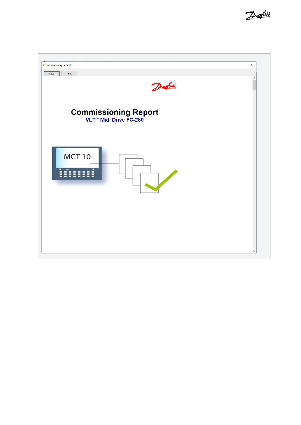
e30bu965.10
VLT® Midi Drive FC 280
Operating Guide
11.
The MCT 10 generates and opens the commissioning report.
Safety Functions
12.
Save and print the commissioning report which is required for future maintenance.
13.
Close the commissioning report dialogue box and the Writing Safety parameters... dialog box.
AQ381425076031en-000101 / 130R122380 | Danfoss A/S © 2022.02

e30bu972.10
VLT® Midi Drive FC 280
Operating Guide
14.
The safety option customization is now complete. A reset may be required depending on the safety option configuration.
Safety Functions
6.7.1.3 Password Protection
Use a password to protect the system configuration. A password must be entered only when changing safety option parameters
(writing to option).
The default password is 12345678.
It is advised to change the safety option default password before downloading the parameter values of a safety option with factory
settings. Only persons knowing the password can change the safety option parameter values.
N O T I C E
Any misuse of the password may lead to safety issues.
N O T I C E
No password is required to access the commissioning parameters of the safety option. The password is required when writing the
parameters to the option via the Write to Drive feature.
The password must consist of 8 characters and is case-sensitive. Alphanumeric characters and symbols are also valid for the password. Use the Change Password menu item to change the safety option parameter password.
6.7.1.3.1 Resetting the Password
If the password is forgotten, the password can be reset using MCT 10.
N O T I C E
Resetting the password resets all option parameters to factory default.
Procedure
1.
In MCT 10, click Administration.
2.
In the Reset tab, select Yes, I want to reset Safety Option configuration in the drive.
3.
Enter the default password (12345678).
4.
Click Reset.
5.
On the prompt that appears, click Yes.
Change the safety option password.
6.
AQ381425076031en-000101 / 130R1223 | 81Danfoss A/S © 2022.02

Bit
Description
State
00
Normal_up
Bit 00, safety function deactive/active.
Bit 00=0, safety function, fail safe reaction is active, or pending, or warning is active.
Bit 00=1, normal operation.
01
PUST
Bit 01, power up self test.
Bit 01=0, safety option is not in PUST state.
Bit 01=1, safety option is in PUST state.
02
STO active
Bit 02, Safe Torque Off.
Bit 02=0, Safe Torque Off is not active.
Bit 02=1, Safe Torque Off is active.
03
SS1-t active
Bit 03, Safe Stop 1.
Bit 03=0, Safe Stop 1 is not active.
Bit 03=1, Safe Stop 1 is active.
04–07
Reserved
–
08
Safe output status
Bit 08, safe output status.
Bit 08=0, safe output at 24 V.
Bit 08=1, safe output at 0 V.
09
Safe option initialized
Bit 09, safe option initialized.
Bit 09=0, not in safe option initialized state.
Bit 09=1, in safe option initialized state.
10
Safe fieldbus acknowledge request
Bit 10, safe fieldbus acknowledge request.
Bit 10=0, no operator acknowledgement requested.
Bit 10=1, operator acknowledgement from safe PLC requested.
11
Int_failure
Bit 11, internal failure.
Bit 11=0, no internal failure is active.
Bit 11=1, an internal failure is active.
12
Reset required
Bit 12, reset.
Bit 12=0, no safety option reset is required.
VLT® Midi Drive FC 280
Operating Guide
Safety Functions
6.7.1.4 Retrieving Safety Option Status
A subset of the safety option status can be retrieved as part of the status word. Its behavior changes based on the selected control
word profile.
Configure the following 2 options in parameter 8-13 Configurable Status Word STW:
•
Configure [91] Safe Opt. Reset. req to indicate that a reset of the safety option is required.
•
Configure [90] Safe Function active to indicate that a safe function is active.
Parameter 42-80 Safe Option Status indicates the actual status (active safe function, any requests, and error number) of the safety
option and is accessible as read only parameter from any interface or configurable as read process data for a specific fieldbus.
N O T I C E
Parameter 42-80 Safe Option Status only shows the active safety function.
6.7.1.4.1 Status Bits for Safety Option Status
Table 38: Status Bits for Safety Option Status
AQ381425076031en-000101 / 130R122382 | Danfoss A/S © 2022.02

Bit
Description
State
Bit 12=1, a safety option reset is required.
13
Pending fail safe state
Bit 13, pending fail safe state.
Bit 13=0, no pending fail safe state.
Bit 13=1, the safety option is in this state at each power-up.
14
Ext_fail ure
Bit 14, external failure.
Bit 14=0, no external failure is active.
Bit 14=1, external failure is active.
15
Safe function pending
Bit 15, safe function pending.
Bit 15=0, no safe function is pending.
Bit 15=1, a safe function is pending.
16
General reset
Bit 16, general reset.
Bit 16=0, no change in state.
Bit 16=1, a general reset is done.
17
Customization_confirmed
Bit 17, customization confirmed.
Bit 17=0, no change in state.
Bit 17=1, customization confirmed by user.
18
Customization_aborted
Bit 18, customization aborted.
Bit 18=0, no change in state.
Bit 18=1, customization aborted by user.
19
Customization_requested
Bit 19, customization requested.
Bit 19=0, no change in state.
Bit 19=1, customization is requested by user.
20
Reserved
–
21
PUST warning
Bit 21, power up self test warning.
Bit 21=0, no change in state.
Bit 21=1, a power up self test warning is issued.
22–23
Reserved
–
24–31
Error code
These bits indicate reasons for internal or external errors. For more information, see the error
codes.
Bit
Description
State
0
DI safety status
00: inactive
01: active
10: pending
11: error
1
VLT® Midi Drive FC 280
Operating Guide
Safety Functions
6.7.1.4.2 Status Bits for Safety Option Status 2
Parameter 42-81 Safe Option Status 2 indicates which digital input of the safety option is activated in pending state or in blank initial
state.
Table 39: Status Bits for Safety Option Status 2
AQ381425076031en-000101 / 130R1223 | 83Danfoss A/S © 2022.02

Bit
Description
State
2–3
Reserved
–
4
Blank initial state
0: inactive
1: active
5
Safe fieldbus support
0: no safe fieldbus supported
1: PROFIsafe supported
2: FSoE supported
3: CIP Safey supported
4: openSAFETY supported
6
7
8
Safe function status on safe fieldbus
0: deactivated
1: activated, safe fieldbus communication is established.
9
Safe fieldbus communication established
0: not established
1: established
10–31
Reserved
–
VLT® Midi Drive FC 280
Operating Guide
Safety Functions
6.7.1.5 Copying Safe Parameter Set-up
To copy the safe parameter set-up to another drive, see the following steps:
Procedure
1.
Prepare a commissioning report.
2.
Select [1] All to LCP in parameter 0-50 LCP Copy. Monitor the upload on the progress bar.
3.
Install the LCP with all the copied parameters on the drive that needs to be updated.
4.
Select [2] All from LCP in parameter 0-50 LCP Copy. The normal password protection can be applied in parameter 0-60 Main
Menu Password.
Enter the password for copied SO configuration (= safe parameters) from LCP.
5.
Accept the download of the safe parameters to the drive, which now has a new configuration assigned to it.
6.
Reset the drive to activate the new configuration.
7.
6.7.1.6 Password Protection LCP Copy and Safe Parameter Mismatch
Optionally, a password protection can be used for the function LCP copy (see
Table 41). Password protection can be enabled/disabled in parameter 0-69 Password Protection of Safety Parameters. The password is
set in parameter 0-68 Safety Parameters Password. Default password is 300.
Table 40) and if there is a parameter mismatch (see
AQ381425076031en-000101 / 130R122384 | Danfoss A/S © 2022.02

Message
Description
e30bd114.11
Password
0-69 Password Protection
of safety Parameter
1(1)
0 RPM None
[1] Enabled
([0] Disabled)
The password protection of the safety parameters is enabled.
e30bd116.11
Copy/Save
0-50 LCP Copy
1(1)
0 RPM None
Safety Par. from LCP
0-5
*
9
[ ]
Copying the safety parameters from the LCP into the drive is selected.
e30bd117.11
Safety Par. from LCP
1(1)
0 RPM None
Copying...
00%
The safety parameters get copied from the LCP into the drive.
e30bd118.11
Safety Password
Please enter the safety
Password
1(1)
0 RPM None
00000000
If password protection is enabled in parameter 0-69 Password Protection of Safety Parameters,
enter the correct LCP-copy/parameter mismatch password (parameter 0-68 Safety Parameters
Password).
e30bd119.11
1(1)
0 RPM None
Password accepted
Pa
0[0
([1] Enabled)
If the entered password is correct, this overlay message is shown for some seconds.
e30bd123.11
1(1)
0 RPM None
Password rejected
Pa
0[0
([1] Enabled)
If the entered password is wrong, this overlay message is shown for some seconds. Then the
password can be entered again.
VLT® Midi Drive FC 280
Operating Guide
Table 40: LCP Copy Messages
Safety Functions
AQ381425076031en-000101 / 130R1223 | 85Danfoss A/S © 2022.02

Message
Description
e30bd120.11
SO Data Confirmation
Are you sure that you want
to overwrite the safety
parameters including the
level 1 password?
!1(1)
0 RPM 0.00A
e30bd121.11
SO Data Confirmation
Press [OK] to confirm
(commissioning test must be
performed) or [CANCEL] to
abort
!1(1)
0 RPM 0.00A
Decision box for continuing overwriting the existing data or to abort the procedure.
e30bd122.11
Status
SO Custom. completed
SO RESET required!
!1(1)
0 RPM None 0.00KW
!Safe Stop [W68]
Off Remote SO Req.RESET
Press [OK] to complete the customization of the safety option. A reset is required to finalize this
procedure.
e30bd124.11
Status
SO Custom. aborted
SO RESET required!
!1(1)
0 RPM None 0.00KW
!Safe Stop [W68]
Off Remote SO Req.RESET
Press [Cancel] to abort the customization of the safety option. A reset is required to finalize this
procedure.
Message
Description
e30bd115.11
SO Param. Selection
Mismatch of SO param.set
detected. Please choose:
!1(1)
0 RPM 0.00 A
SO : Test1234_ 1.00
VLT : SafeSet1_ 1.00
Whenever there is a mismatch of safety parameters within the safety option and the drive, this
selection form is shown on the LCP. Select between the Safety data on safe option or the Safety
data on drive valid data.
e30bd122.11
Status
SO Custom. completed
SO RESET required!
!1(1)
0 RPM None 0.00KW
!Safe Stop [W68]
Off Remote SO Req.RESET
If selecting [SO:…], the customization of the safety option is completed and a reset is required
to finalize this procedure.
VLT® Midi Drive FC 280
Operating Guide
Safety Functions
Table 41: Mismatch Between Safety Parameters in the Safety Option and in the Drive
AQ381425076031en-000101 / 130R122386 | Danfoss A/S © 2022.02

Message
Description
e30bd118.11
Safety Password
Please enter the safety
Password
1(1)
0 RPM None
00000000
If selecting [VLT:…] and the password protection in parameter 0-69 Password Protection of Safety Parameters is enabled, enter the correct LCP-copy/parameter mismatch password (parameter
0-68 Safety Parameters Password).
e30bd119.11
1(1)
0 RPM None
Password accepted
Pa
0[0
([1] Enabled)
If the entered password is correct, this overlay message is shown for some seconds.
e30bd123.11
1(1)
0 RPM None
Password rejected
Pa
0[0
([1] Enabled)
If the entered password is wrong, this overlay message is shown for some seconds. Then the
password can be entered again.
e30bd120.11
SO Data Confirmation
Are you sure that you want
to overwrite the safety
parameters including the
level 1 password?
!1(1)
0 RPM 0.00A
Decision box for continuing overwriting the existing data or to abort the procedure.
VLT® Midi Drive FC 280
Operating Guide
Safety Functions
AQ381425076031en-000101 / 130R1223 | 87Danfoss A/S © 2022.02

Message
Description
e30bd121.11
SO Data Confirmation
Press [OK] to confirm
(commissioning test must be
performed) or [CANCEL] to
abort
!1(1)
0 RPM 0.00A
e30bd122.11
Status
SO Custom. completed
SO RESET required!
!1(1)
0 RPM None 0.00KW
!Safe Stop [W68]
Off Remote SO Req.RESET
Press [OK] to complete the customization of the safety option. A reset is required to finalize this
procedure.
e30bd124.11
Status
SO Custom. aborted
SO RESET required!
!1(1)
0 RPM None 0.00KW
!Safe Stop [W68]
Off Remote SO Req.RESET
Press [Cancel] to abort the customization of the safety option. A reset is required to finalize this
procedure.
e30be085.11
VLT® Midi Drive FC 280
Operating Guide
Safety Functions
6.7.2 Configuring PROFIsafe with Siemens TIA Portal
This section explains how to configure PROFIsafe communication between VLT® Midi DriveFC 280 and Siemens device with Siemens
TIA Portal.
6.7.2.1 Configuring the Hardware
Configure the PROFINET communication with the F-PLC using the VLT® PROFINET MCA 120 Installation Guide.
Procedure
1.
In the Siemens TIA Portal, select Open the project view.
2.
Double-click Devices and Networks.
The Hardware Configuration dialog box opens.
Select the Danfoss device in the network view and drag it into the workspace.
3.
The project view shows the F-PLC and the Danfoss device.
AQ381425076031en-000101 / 130R122388 | Danfoss A/S © 2022.02

e30be086.11
e30be087.11
e30be088.11
VLT® Midi Drive FC 280
Operating Guide
4.
In the Password for Safety Program dialog box, enter the appropriate password.
5.
Assign the name to the Danfoss device. The name must be the same as shown in parameter 12-08 Host Name.
Safety Functions
6.
Select the following I/O protocol: PROFIsafe 30 -6/6 Bytes, Standard Telegram 30.
7.
Edit the required PROFIsafe settings under the Properties tab.
The following parameters can be changed, but normally it is only necessary to change the F_Dest_Add parameter:
•
F_Source_Add - the PROFIsafe address of the PROFIsafe master.
•
F_Dest_Add - the destination address of the safety option. This address must be the same as set in the VLT® Motion
Control Tool MCT 10 software, parameter 42-61 Destination Address.
•
F_WD_Time - the watchdog time for the PROFIsafe connection. This setting depends on the speed of the PROFINET
connection and the number of slaves.
•
F_iPar_CRC - if the F_iPar_CRC module is enabled. To set up communication, copy the value of parameter 42-35 S-CRC
Value from the VLT® Motion Control Tool MCT 10 software and insert the value here.
AQ381425076031en-000101 / 130R1223 | 89Danfoss A/S © 2022.02

e30bv049.10
VLT® Midi Drive FC 280
Operating Guide
Safety Functions
6.7.3 Programming Safety Functions with Siemens TIA Portal
Refer to the Siemens documentation for more information on distributed safety. Refer to the following documentation for information on how to use safety inputs and outputs for passivation and reintegration.
•
Industrial Software SIMATIC Safety - Configuring and Programming. Programming and Operating Manual.
•
Fail-safe Controllers SIMATIC Safety Integrated. Emergency Stop with Acknowledgment in Category 4 according to EN 954-1.
•
Fail-safe Controllers SIMATIC Safety Integrated. Passivation and Reintegration of F-I/O considering as example the ET 200S.
6.8 Reset Function
When the safety function is activated, reset the safety option. Depending on the configuration, the following sources can reset the
safety option:
The [Reset] key on the LCP or the drive’s digital input.
•
The reset signal via the safe fieldbus.
•
Parameter 42-24 Restart Behavior determines whether the safety option restarts automatically, or waits for a manual reset after the
safety function was activated:
Manual reset behavior - when the safety function is activated, the safety option requires a reset from a reset source before it can
•
run again.
Automatic reset behavior - when the safety function is activated, the safety option can run again when the condition that trig-
•
gered the safety function ceases. This behavior is only valid for the digital input where this reset behavior is defined. For instance, if there is an external error, a manual reset from the reset source is required regardless of the setting in Parameter 42-24
Restart Behavior.
For more information, read the description of parameter 42-31 Reset Source.
AQ381425076031en-000101 / 130R122390 | Danfoss A/S © 2022.02

VLT® Midi Drive FC 280
Operating Guide
Safety Functions
6.9 Commissioning and Validation
6.9.1 Safety Guidelines
N O T I C E
Always perform a commissioning test after installation, maintenance, retrofit, and reconfiguration.
When commissioning/recommissioning:
•
Secure the site in accordance with regulations (barrier, warnings, signs, and so on).
•
Only qualified personnel are allowed to commission/recommission the system.
•
Refer to the guidelines, information, and specifications stated in the Operating Instructions of relevant programmable control
system.
•
Make sure that no personal injury and/or material damage can occur, even if the plant/machine moves unintentionally.
C A U T I O N
ELECTROSTATIC DISCHARGE
Electrostatic discharge can damage components.
Ensure discharge before touching the safety option, for example, by touching a grounded, conductive surface or by wearing
-
a grounded armband.
W A R N I N G
RISK OF ELECTROCUTION
Never wire the electrical connections on the drive while voltage is applied.
-
Switch off power.
-
Make sure that the control cabinet is provided with access lock or warning signs.
-
DO NOT switch on the voltages until the system is commissioned.
-
Refer to other chapters of this Operating Guide for further information of the drive. Refer to VLT® Motion Control Tool MCT 10 Operating Guide for further information on the Safe Plug-in.
6.9.2 Commissioning Requirements
The procedure requires installation of MCT 10 setup software, version 5.30 or later, and a successful connection to VLT® Midi
Drive FC 280 with built-in safety option.
•
Configure the safety option in the MCT 10 with safe plug-in. Ensure only to configure safety functions that are wired up to the
safety option inputs.
•
Ensure that the device number (serial number and order number) of the safety option on the drive matches the device number
of the safety option in the MCT 10 safe plug-in.
•
Ensure that the drive is ready for commissioning.
The following components are required to perform the necessary steps for commissioning the safety option.
•
VLT® Motion Control Tool MCT 10 set-up software (licensed version).
•
USB or fieldbus connection or RS485 interface adaptor for connecting the control card of the drive with the PC.
If RS485 is used, the protocol for serial communication needs to be set to [0] FC-MC in parameter 8-30 Protocol (only accessible
through the LCP). When setting up the option for the first time, ensure to have a commissioning report at hand, see further information in VLT® Motion Control Tool MCT 10 Operating Guide.
Only LCP software version 7.0 or newer is supported.
N O T I C E
AQ381425076031en-000101 / 130R1223 | 91Danfoss A/S © 2022.02

•
•
•
•
•
•
Safety functions
Test procedure
Approved ✓
STO
1. STO function must be inactive:
Via digital input.
Via PROFIsafe.
Check the STO circuit connections against the circuit diagram.
2. No safety faults and alarms.
3. Run the drive.
4. Ensure that the correct drive is running.
5. Trigger STO while the drive is running.
6. Check the following:
The drive coasts to zero speed.
The motor is braked and stopped by the mechanical brake (if available and configured).
Warning 68 is displayed.
VLT® Midi Drive FC 280
Operating Guide
Safety Functions
6.9.3 Commissioning Test
EN IEC 61508, EN IEC 62061, and EN ISO 13849 require that the final assembler of the machine validates the operation of the safety
function with a commissioning test. The tests for the configured safety functions are described in the commissioning report generated by the MCT 10 safe plug-in.
The commissioning test must be performed in the following cases:
•
At initial start-up of the safety option.
•
After any changes related to the safety function (wiring, components, parameter settings, and so on).
•
After any maintenance work related to the safety function.
The commissioning test for systems with safety functions is focused on:
•
Validating the functionality of safety monitoring and stop functions configured in the drive system.
•
Correct selection of the safety option parameter values.
•
Examining the response of specific monitoring functions to the explicit input of values outside tolerance limits.
Perform the commissioning test on the basis of the risk analysis. Adhere to all applicable standards and regulations.
Ensure that the following preconditions are met:
•
The drive is wired properly. For more information about wiring, see chapter Installation.
•
All safety equipment such as protective monitoring devices, light barriers, or emergency stop switches are connected and ready
for operation.
•
All motor parameters and command parameters are set correctly in the drive.
6.9.3.1 Performing the Commissioning Test
Procedure
1.
Use MCT 10 set-up software to generate the commissioning test report.
2.
Follow the test sequence in the report to ensure proper functioning of the safety option.
3.
Document each individual step of the test.
4.
Note the checksum of the safety option parameters in the records.
5.
Do not release the system unless it has successfully passed all individual steps of the test.
6.
Restart the drive and check that the motor runs normally.
6.9.4 Commissioning Test Report
After some operations, for example LCP copy of safe parameters, a commissioning test is required. Follow and approve the test
sequence according to the commissioning test report.
Table 42: Commissioning Test Report: Safe Torque Off
AQ381425076031en-000101 / 130R122392 | Danfoss A/S © 2022.02

•
•
•
•
•
•
•
•
•••
Safety functions
Test procedure
Approved ✓
7. Deactivate STO.
8. Check the following:
Depending on the configuration, Safety Func. Pending is displayed.
STO inactive.
9. Restart the drive and check that the motor runs normally.
10. Ensure that the STO function is safe and accepted to operate.
11. Document and sign the commissioning test report.
Safety functions
Test procedure
Approved ✓
SS1-t
1. SS1-t function must be inactive:
Via digital input.
Via PROFIsafe.
Check the SS1-t circuit connections against the circuit diagram.
2. No safety faults and alarms.
3. Run the drive.
4. Ensure that the correct drive is running.
5. Trigger SS1-t while the drive is running.
6. Check the following:
The drive is ramping down to zero speed.
The motor stops within the demanded time delay.
The motor is braked and stopped by the mechanical brake (if available and configured).
Warning 68 is displayed.
7. Deactivate SS1-t.
8. Check the following:
Depending on the configuration, Safety Func. Pending is displayed.
SS1-t inactive.
9. Restart the drive and check that the motor runs normally.
10. Ensure that the SS1-t function is safe and accepted to operate.
11. Document and sign the commissioning test report.
VLT® Midi Drive FC 280
Operating Guide
Table 43: Commissioning Test Report: Safe Stop 1 Time Controlled
Safety Functions
AQ381425076031en-000101 / 130R1223 | 93Danfoss A/S © 2022.02

Error
code
Description
Reason
Action
1–32
Internal fault
An internal fault is detected by diagnosis.
Repower, if irrecoverable,
contact Danfoss service
support.
113
DI discrepancy
One of the safety inputs
fail.
Check the connection of
T37 and T38 and the device connected on them.
119
Safety layer diagnosis messages 64: mismatch of safety
destination address (F_Dest_Add)
––120
Safe fieldbus telegram mismatch, reaction: STO.
PFOFIdrive telegram other
than 30 is received.
–
VLT® Midi Drive FC 280
Operating Guide
Safety Functions
6.10 Operation and Maintenance
6.10.1 Safe Operation
W A R N I N G
UNINTENDED BEHAVIOR
Numerous stored data or settings determine the behavior of the drive system. Unsuitable settings or data may trigger unexpected movements or responses to signals and disable monitoring functions. Failure to follow these instructions can result in death,
serious injury, or equipment damage.
Do not operate the drive system with unknown settings or data.
-
Verify that the stored data and settings are correct.
-
When commissioning, run tests for all operating states and potential error situations carefully.
-
Verify the functions after replacing the product and changing the settings or data.
-
Only start the system when there is no person or obstructions in the hazardous area.
-
Prerequisites for normal operation:
•
Commissioning is complete.
•
The safety option contains the configuration data.
•
The safety functions have been tested.
During operation:
•
The safety option monitors any pulse changes at its safe inputs.
•
The safety option executes safety functions according to the configuration.
6.10.2 Firmware Update and Modification
N O T I C E
Contact Danfoss for advice on the firmware update.
C A U T I O N
FIRMWARE MODIFICATIONS IN SAFE OPTION
Only Danfoss is authorized to change the firmware in Safe Option. If other parties make changes to the firmware, the warranty
becomes void. Furthermore, Danfoss cannot be held liable for any consequences the changes may have on the functional safety.
6.10.3 Troubleshooting
Table 44: List of Fault Conditions
AQ381425076031en-000101 / 130R122394 | Danfoss A/S © 2022.02

Error
code
Description
Reason
Action
121
F-parameter error.
The received F-parameter
is invalid.
Check the F-parameter in
F-host.
122
Data inconsistent in received F-parameter block (CRC1
error).
–
–
123
Inconsistent iParameters (iParCRC error).
––124
Transmission error: data inconsistent (CRC2 error).
––125
Transmission error: timeout (F_WD_Time).
––126
CGP is not supported in F-module.
–
–
Safety standards
E/E/PE
IEC 61508
Machinery system
ISO 13849-1
E/E/PE in machinery system
IEC 62061
Drive
IEC 61800-5-2
Safety functions
STO
SS1-t
IEC 61800-5-2
Safety performance
ISO 13849-1
Category
Cat.3
Diagnostic coverage (DC)
90%<DC
avg
<99% (medium)
Mean time to dangerous failure (MTTFD)
350 years (high)
Performance level
PL e
IEC 61508/IEC 61800-5-2/IEC 62061
Safety Integrity Level
SIL Claim Limit (SIL CL)
SIL3
VLT® Midi Drive FC 280
Operating Guide
Safety Functions
6.11 Safety Technical Data
6.11.1 Condition and Assumption
The Failure Modes, Effects, and Diagnostic Analysis (FMEDA) is performed based on the following assumptions:
•
VLT® Midi DriveFC 280 takes 20% of the total failure budget for an SIL3 safety loop.
•
Failure rates are based on the Siemens SN29500 database.
•
Failure rates are constant; wear-out mechanisms are not included.
•
For each channel, the safety-related components are considered to be of type B with a hardware fault tolerance of 0.
•
The stress levels are average for an industrial environment and the working temperature of components is up to 85 °C (185 °F).
•
A safe error (for example output in safe state) is repaired within 8 hours.
•
No torque output is the safe state.
6.11.2 Safety Technical Data
Table 45: Safety Functions via Digital Input (T37/T38)
AQ381425076031en-000101 / 130R1223 | 95Danfoss A/S © 2022.02

Probability of dangerous failure on demand (PFD
avg
)
(1)
2.5x10
-4
Probability of dangerous failure per hour (PFH)
9.0 FIT
(2)
Safe failure fraction (SFF)
For dual-channel parts: >93%
For single-channel parts: >99%
Hardware fault tolerance (HFT)
For dual-channel parts: HFT=1
For single-channel parts: HFT=0
Proof test interval (PTI)
(3)
20 years
Common cause failure (CCF)
β=5%; βD=2%
Diagnostic test interval (DTI)
<10 minutes
Systematic capability
SC 3
STO reaction time
Input to output response time
(4)
≤110 ms
Safety standards
E/E/PE
IEC 61508
Machinery system
ISO 13849-1
E/E/PE in machinery system
IEC 62061
Drive
IEC 61800-5-2
Safety fieldbus
IEC 61784-3-3
Safety functions
STO
SS1-t
IEC 61800-5-2
Safety performance
ISO 13849-1
Category
Cat.3
Diagnostic coverage (DC)
90%<DC
avg
<99% (medium)
Mean time to dangerous failure (MTTFD)
350 years (high)
Performance level
PL e
IEC 61508/IEC 61800-5-2/IEC 62061
Safety Integrity Level
SIL Claim Limit (SIL CL)
SIL3
Probability of dangerous failure per hour (PFH)
9.0 FIT
(1)
Safe failure fraction (SFF)
For dual-channel parts: >93%
VLT® Midi Drive FC 280
Operating Guide
1
PFD
is not suitable for the drive due to the fact that it is assumed to be working in continuous mode in IEC 61800-5-2. Here, PFD
avg
ence purposes only.
2
1 FIT=1/(109 hour).
3
For proof test procedure, refer to chapter Operation and Maintenance.
4
STO reaction time via digital input is the amount of time from an input signal condition triggers the STO until the torque is removed from the
motor interface.
Safety Functions
is for refer-
avg
Table 46: Safety Functions via Safety Fieldbus
AQ381425076031en-000101 / 130R122396 | Danfoss A/S © 2022.02

•
•
•
For single-channel parts: >99%
Hardware fault tolerance (HFT)
For dual-channel parts: HFT=1
For single-channel parts: HFT=0
Proof test interval (PTI)
(2)
20 years
Common cause failure (CCF)
β=5%; βD=2%
Diagnostic test interval (DTI)
<10 minutes
Systematic capability
SC 3
STO reaction time
Drive worst case delay time (WCDT)
≤70 ms
Bus delay time (BT)
≤4 ms
Input to output response time
(3)
≤120 ms
Parameter
Option/range
Default
Usage
Conversion
index
Data
type
Parameter 42-20
Safe Function
[0] STO
[5] Disable
[9] SS1-t
[5] Disable
Select the safety function when the safe input is active.
–
u_int8
Parameter 42-24
Restart Behavior
[0] Manual
[1] Automatic
[0] Manual
Select whether the safety option restarts automatically or waits for a manual reset after the safety function was activated via a digital input.
–
u_int8
Parameter 42-30
External Failure
Reaction
[0] STO
[3] SS1-t
[0] STO
Select which safety function is executed if there is an
external failure.
–
u_int8
Parameter 42-31
Reset Source
[0] Drive Reset
[1] Drive Safe Re-
set
[0] Drive
Reset
Select the source that triggers the safety option reset.
The reset sources of [0] Drive Reset are:
The [Reset] key on the LCP.
Digital input.
Reset signal via a fieldbus.
If there is an active alarm on the drive, the 1st the
drive, and the 2nd safety option.
–
u_int8
VLT® Midi Drive FC 280
Operating Guide
1
1 FIT=1/(109 hour).
2
For proof test procedure, refer to chapter Operation and Maintenance.
3
STO reaction time via fieldbus is the amount of time from an STO command received until the torque is removed from the motor interface.
Safety Functions
6.12 Safety-related Parameters
Table 47: Safety Related Parameters
AQ381425076031en-000101 / 130R1223 | 97Danfoss A/S © 2022.02

•
•
Parameter
Option/range
Default
Usage
Conversion
index
Data
type
The reset sources of [1] Drive Safe Reset are:
Digital input (Select [100] Safe Option Reset on 1
of the digital inputs for this source type to work).
The reset signal via a fieldbus. (For the fieldbus
reset to work, set parameter 8-14 Configurable
Control Word CTW to [3] Safe Option Reset.)
Parameter 42-33
Parameter Set
Name
–
SafeSet1
Enter the name of the safety parameter set (8 characters). Use this parameter to identify the safety configurations.
–
Visible
String
Parameter 42-35
S-CRC Value
––The CRC value of safe parameter set.
–
u_int16
Parameter 42-36
Level 1 Password
–
12345678
Password for safe parameter set to prevent unauthorized modification.
–
Visible
String
Parameter 42-42
Delay Time
0.1-3600.0 s
10.0 s
Time until STO is activated.
-1
u_int16
Parameter 42-43
Delta T
0-99%
2%
The value subtracts from the time in parameter 42-42
Delay Time to get motor to stop before the timer expires.
0
u_int8
Parameter 42-60
Telegram Selection
[0] None
[1] PROFIsafe
Std. Tel. 30
[0] None
Select the safe fieldbus type and the telegram standard for the safety option.
Selecting [0] None means the safe fieldbus communication is disabled.
Selecting [1] PROFIsafe Std. Tel. 30 means the PROFIsafe communication is enabled, and the telegram
standard is PROFIsafe Std. Tel. 30. PROFIsafe Std. Tel.
30. For more information, see
6.5.1 PROFIsafe.
If the fieldbus communication is enabled and the reset signal comes via the fieldbus, this parameter also
defines whether the drive is reset or only the safety
option is reset.
–
u_int8
Parameter 42-61
Destination Address
1-65534
1
Enter the safe fieldbus destination address within the
safe network. This address must be unique in the network where PROFIsafe operates. The address should
match the address specified in the PLC software.
–
u_int16
Parameter 42-80
Safe Option Status
0-0xFFFFFFFF
0
Show the status word 1 of the safety option as a hexadecimal value. Refer to Table 48.
0
u_int32
Parameter 42-81
Safe Option Status
2
0-0x7FFFFFFF
0
Show the status 2 word of the safety option as a hexadecimal value. Refer to Table 49.
0
u_int32
Parameter 42-82
Safe Control Word
0-0xFFFFFFFF
0
Show the safe control word as a hexadecimal value.
–
u_int32
Parameter 42-83
Safe Status Word
0-0xFFFFFFFF
0
Show the safe status word as a hexadecimal value.
–
u_int32
VLT® Midi Drive FC 280
Operating Guide
Safety Functions
AQ381425076031en-000101 / 130R122398 | Danfoss A/S © 2022.02

Parameter
Option/range
Default
Usage
Conversion
index
Data
type
Parameter 42-85
Active Safe Func.
[0] STO
[9] SS1-t
[10] None
[10] None
Show the currently active safety function. Use param-
eter 0-20 Display Line 1.1 Small to parameter 0-22 Display Line 1.3 Small to show the function on the LCP.
–
u_int8
Parameter 42-86
Safe Option Info
–0Show the information about the safety option. Use
parameter 0-23 Display Line 2 Large and parameter
0-24 Display Line 3 Large to show the function on the
LCP large display line.
0
Visible
String
Parameter 42-88
Supported Customization File
Version
0.00-99.99
2.00
Show the maximum supported configuration file version.
0.00 means the maximum version supported by the
safe system (the drive with the safety option).
1.00 means the maximum version supported by the
safety option.
2.00 means the maximum version supported by the
control card.
-2
u_int16
Parameter 42-89
Customization File
Version
0.00-99.99
2.00
Show the currently used customization file version.
-2
u_int16
Parameter 600-44
Fault Message
Counter
0-65535
0
Is incremented each time that the fault buffer
changes.
–
u_int16
Parameter 600-47
Fault Number
0-65535
0
Contain the internal fault number for each fault message.
–
u_int16
Parameter 600-52
Fault Situation
Counter
0-65535
0
Sum of all of the fault situations since the last reset.
–
u_int16
Bit
Name
Description
0
Normal up
0: Safety function, fail safe reaction is active or pending or warning is active.
1: Normal operation.
1
PUST
0: SFBC is not in PUST state.
1: SFBC in PUST state.
2
STO active
0: STO is not active.
1: STO is active.
3
SS1-t active
0: SS1-t is not active.
1: SS1-t is active.
4–7
Reserved
–
8
Safe output status
The safe output status of SFBC (from SFBC to PU).
0: Safe output deactivated.
1: Safe output activated.
VLT® Midi Drive FC 280
Operating Guide
Safety Functions
Table 48: Status Word 1
AQ381425076031en-000101 / 130R1223 | 99Danfoss A/S © 2022.02

Bit
Name
Description
9
SFBC initialized
0: Not in SFBC initialized state.
1: In SFBC initialized state.
10
Safe fieldbus acknowledge request
Indicating if the PROFIsafe PLC is requesting operator acknowledge or not.
0: No operator acknowledgment requested.
1: Operator acknowledgment requested from safe PLC.
11
Internal failure
0: No internal failure is active.
1: An internal failure is active.
12
Reset Required
0: No SFBC reset is required.
1: A SFBC reset is required.
13
Pending fail safe state
0: No pending fail safe state.
1: In pending fail safe state.
14
External failure
0: No external failure is active.
1: An external failure is active.
15
Safe function pending
0: No safe function is pending.
1: A safe function is pending.
16
General reset
0: No change in state.
1: A General Reset is done.
17
Customization confirmed
0: No change in state.
1: Customization confirmed.
18
Customization aborted
0: No change in state.
1: Customization aborted.
19
Customization requested
0: No change in state.
1: Customization is requested.
20
Reserved
–
21
PUST warning
0: No change in state.
1: A power-up selftest warning is issued.
22–23
Reserved
–
24–31
Error code
This is the internal or external error codes. 8 bits can indicate 256 different errors. Refer to
6.10.3 Troubleshooting for the definition of the error codes.
Bit
Name
Description
0–1
DI safety status
00: Inactive
01: Active
10: Pending
11: Error
2–3
Reserved
–
VLT® Midi Drive FC 280
Operating Guide
Safety Functions
Table 49: Status Word 2
AQ381425076031en-000101 / 130R1223100 | Danfoss A/S © 2022.02
 Loading...