

Operating Guide
VLT® AQUA Drive FC 202
110-800 kW, D9h-D10h and E5h-E6h Enclosed Drives
drives.danfoss.com


VLT® AQUA Drive FC 202
Operating Guide
Contents
1
Introduction 8
1.1
Purpose of this Operating Guide 8
Additional Resources 8
1.2
Manual Version 8
1.3
1.4
Approvals and Certifications 8
1.5
Finding the Declaration of Conformity Certificate 9
1.6
Declaration of Conformity Certificate 10
Safety 14
2
Safety Symbols 14
2.1
Qualified Personnel 14
2.2
Safety Precautions 15
2.3
3
Product Overview 17
Contents
3.1
Intended Use 17
3.2
What is an Enclosed Drive? 17
3.3
Location of Options within an Enclosed Drive 20
3.4
Drive Identification 22
3.4.1
Identifying the Drive and Its Options 22
3.4.2
Enclosure Size Identification 23
3.4.3
Type Code Identification 24
3.5
Power Ratings, Weight, and Dimensions 31
3.6
Control Compartment and Local Control Panel 33
3.6.1
Control Compartment Overview 33
3.6.2
Control Compartment Door 34
3.6.3
Local Control Panel (LCP) 35
3.6.4
LCP Menu 37
4
Mechanical Installation 39
4.1
Items Supplied 39
4.2
Split Shipment 39
4.3
Tools Needed 40
4.4
Storing the Drive 40
4.5
Operating Environment 40
4.5.1
Overview 40
4.5.2
Gases 40
4.5.3
Dust 40
4.5.4
Potentially Explosive Atmospheres 41
AQ262141056213en-000201/130R0882 | 3Danfoss A/S © 2021.11

VLT® AQUA Drive FC 202
Operating Guide
4.6
Installation Requirements 41
4.7
Cooling Requirements 42
4.8
Airflow Rates 42
4.9
Lifting the Drive 44
4.10
Combining Multiple Cabinets from a Split Shipment 44
4.11
Installing the Enclosed Drive 46
4.11.1
Creating an Entry for Cables 46
4.11.2
Installing the Drive with Back-channel Cooling Option 46
4.11.3
Securing the Cabinet(s) to the Floor 47
5
Electrical Installation 49
5.1
Safety Instructions 49
5.2
EMC-compliant Installation 49
5.3
Wiring Overview for D9h and D10h Enclosed Drives 53
5.4
Wiring Overview for E5h and E6h Enclosed Drives 54
Contents
5.5
Control Terminal Wiring Diagram Cross-reference 55
5.6
Split Shipment Wiring Harnesses 56
5.6.1
Connecting Wiring Harnesses 56
5.6.2
Cable Routing 57
5.6.3
D10h Wiring Harness 65
5.6.4
E5h Wiring Harness 69
5.6.5
E6h Wiring Harness 75
5.7
Control Compartment Wiring 81
5.7.1
Safety Precautions 81
5.7.2
Control Compartment Interior View 82
5.7.3
Control Terminals 83
5.7.4
Relay Terminals 84
5.7.5
Option Card Terminals 84
5.7.6
Control Compartment Options 88
5.8
Connecting Motor, Mains, and Ground Cables 95
5.8.1
Power Cabling and Grounding Considerations 95
5.8.2
Connecting to the Mains 96
5.8.3
Connecting the Drive Module to the Motor 98
5.8.4
Connecting the Sine-wave Filter to the Motor 100
5.8.5
Connecting the dU/dt Filter to the Motor 101
5.8.6
Connecting to Ground 103
5.9
Installing Upstream Fuses 104
5.9.1
Upstream Fuse Considerations 104
AQ262141056213en-000201/130R08824 | Danfoss A/S © 2021.11

VLT® AQUA Drive FC 202
Operating Guide
5.9.2
Recommended Fuse Ratings for IEC Installation 104
5.9.3
Recommended Fuse Ratings for UL Installation 105
5.10
Enabling Motor Operation 106
5.11
Selecting the Voltage/Current Input Signal 106
5.12
Setting Up RS485 Serial Communication 107
5.13
Configuring the Passive Harmonic Filter (PHF) 108
5.14
Configuring the dU/dt Filter 108
5.15
Configuring the Sine-wave Filter 108
5.16
MCCB Configuration 108
5.17
Safe Torque Off (STO) Wiring 109
6
Pre-start Check 110
7
Commissioning 112
7.1
Applying Power to the Drive 112
Contents
7.2
Programming the Drive 112
7.2.1
Parameter Overview 112
7.2.2
Parameter Navigation 113
7.2.3
Programming Example for an Open-loop Application 113
7.2.4
Entering System Information 114
7.2.5
Configuring Automatic Energy Optimization 115
7.2.6
Configuring Automatic Motor Adaptation 115
7.3
Testing Before System Start-up 115
7.3.1
Testing Motor Rotation 115
7.3.2
Testing Encoder Rotation 115
7.4
Starting Up the Drive for the First Time 116
7.5
Parameter Settings 116
7.5.1
Parameter Setting Overview 116
7.5.2
Uploading and Downloading Parameter Settings 116
7.5.3
Restoring Factory Default Settings Using the Recommended Initialization 117
7.5.4
Restoring Factory Default Settings Using Manual Initialization 117
8
Wiring Configuration Examples 118
8.1
Application Examples 118
8.1.1
Wiring Configuration for Automatic Motor Adaptation (AMA) 118
8.1.2
Wiring Configuration for Automatic Motor Adaptation (AMA) without T27 118
8.1.3
Wiring Configuration: Speed 119
8.1.4
Wiring Configuration: Feedback 121
8.1.5
Wiring Configuration: Run/Stop 122
AQ262141056213en-000201/130R0882 | 5Danfoss A/S © 2021.11

VLT® AQUA Drive FC 202
Operating Guide
8.1.6
Wiring Configuration: Start/Stop 124
8.1.7
Wiring Configuration: External Alarm Reset 126
8.1.8
Wiring Configuration: RS485 126
8.1.9
Wiring Configuration: Motor Thermistor 127
8.1.10
Wiring for Regeneration 127
8.1.11
Wiring Configuration for a Relay Set-up with Smart Logic Control 128
8.1.12
Wiring Configuration for a Submersible Pump 128
8.1.13
Wiring Configuration for a Cascade Controller 130
8.1.14
Wiring Configuration for a Fixed Variable Speed Pump 131
8.1.15
Wiring Configuration for Lead Pump Alternation 132
9
Maintenance, Diagnostics, and Troubleshooting 133
9.1
Maintenance and Service 133
9.2
Disposal 133
9.3
Status Messages 133
Contents
9.4
Warnings and Alarms 137
9.5
Troubleshooting 153
10
Specifications 156
10.1
Electrical Data 156
10.1.1
Electrical Data, 380–480 V AC 156
10.1.2
Electrical Data, 525–690 V AC 161
10.2
Mains Supply 166
10.3
Motor Output and Motor Data 166
10.3.1
Motor Output (U, V, W) 166
10.3.2
Torque Characteristics 167
10.4
Ambient Conditions 167
10.5
Motor and Control Cables 167
10.6
Control Input/Output and Control Data 168
10.6.1
Control Card, USB Serial Communication 168
10.6.2
STO Terminal XD2.19 (Terminal XD2.19 is Fixed PNP Logic) 168
10.6.3
Control Card, 24 V DC Output 168
10.6.4
Control Card, 10 V DC Output 168
10.6.5
Digital Outputs 169
10.6.6
Digital Inputs 169
10.6.7
Pulse/Encoder Inputs 169
10.6.8
Control Characteristics 170
10.6.9
Relay Outputs 170
10.6.10
Analog Output 171
AQ262141056213en-000201/130R08826 | Danfoss A/S © 2021.11

VLT® AQUA Drive FC 202
Operating Guide
10.6.11
10.6.12
10.6.13
10.7
Filter Specifications 172
10.7.1
10.7.2
10.7.3
10.7.4
10.8
Fuses, Circuit Breakers, and Switches 174
10.8.1
10.8.2
10.8.3
10.8.4
10.8.5
Contents
Analog Inputs 171
Control Card, RS485 Serial Communication 171
Control Card Performance 171
Passive Harmonic Filter Specifications 172
Line Reactor Specifications 172
dU/dt Filter Specifications 173
Sine-wave Filter Specifications 173
Panel Fuses 175
Contactor Switches 176
Fusible Disconnect Switches 177
Non-fusible Disconnect Switches 178
Molded-case Circuit Breakers 179
10.9
Enclosure Dimensions 180
10.9.1
Pedestal Dimensions 180
10.9.2
D9h Enclosed Drive Exterior Dimensions 180
10.9.3
D10h Enclosed Drive Exterior Dimensions 181
10.9.4
E5h Enclosed Drive Exterior Dimensions 182
10.9.5
E6h Enclosed Drive Exterior Dimensions 183
10.10
Enclosure Airflow 184
10.11
Fastener Torque Ratings 184
11
Appendix 185
11.1
Conventions 185
11.2
Abbreviations 185
11.3
International/North American Default Parameter Settings 187
11.4
Required Parameter Settings for Drive Options 188
11.5
Block Diagrams 189
11.6
Input Power Option Losses 192
11.6.1
Contactor Losses 192
11.6.2
Fusible Disconnect Losses 193
11.6.3
Non-fusible Disconnect Losses 194
11.6.4
Molded-case Circuit Breaker (MCCB) Losses 195
11.6.5
Passive Harmonic Filter Losses 196
11.6.6
Line Reactor Losses 197
11.6.7
dU/dt Filter Losses 198
11.6.8
Sine-wave Filter Losses 199
AQ262141056213en-000201/130R0882 | 7Danfoss A/S © 2021.11
Version
Remarks
Software version
AQ262141056213 - 0201
Updated illustrations and power loss tables.
3.40
MG80H1xx
First version
3.31
089
VLT® AQUA Drive FC 202
Operating Guide
Introduction
1 Introduction
1.1 Purpose of this Operating Guide
This Operating Guide provides information for safe installation and commissioning of the AC drive. It is intended for use by qualified
personnel.
Read and follow the instructions to use the drive safely and professionally.
Pay particular attention to the safety instructions and general warnings. Always keep this Operating Guide with the drive.
VLT® is a registered trademark for Danfoss A/S.
1.2 Additional Resources
Other resources are available to understand advanced drive functions and programming.
•
The Programming Guide provides detailed information on the LCP, menu system, parameters, and troubleshooting with alarms
and warnings.
•
The Design Guide provides detailed information about capabilities and functionality to design motor control systems.
•
The Safe Torque Off Operating Guide provides detailed specifications, requirements, and installation instructions for the Safe
Torque Off function.
•
Supplementary publications and manuals are available from Danfoss, see
1.3 Manual Version
This manual is regularly reviewed and updated. All suggestions for improvement are welcome.
The original language of this manual is English.
www.danfoss.com.
Table 1: Manual and Software Version
1.4 Approvals and Certifications
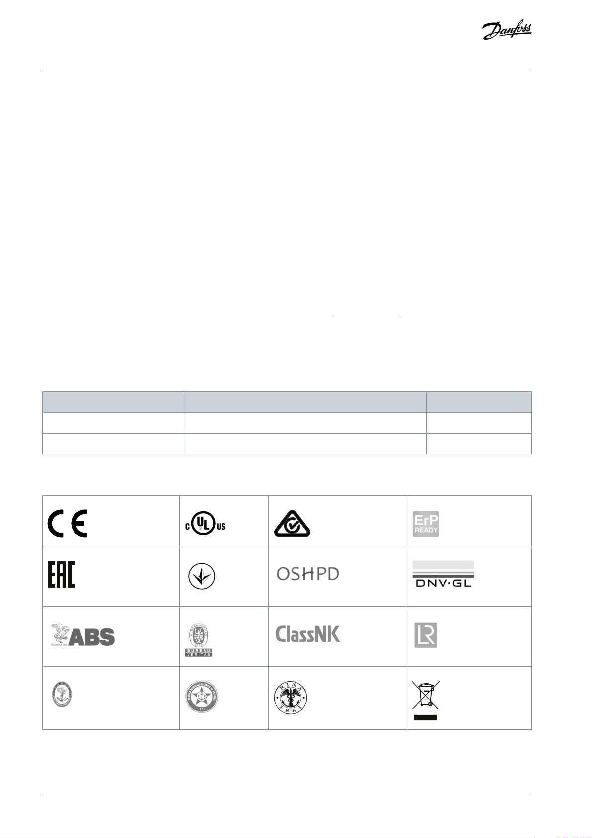
The following list is a selection of possible type approvals and certifications for Danfoss drives:
The specific approvals and certification for the enclosed drive or drive module are on the nameplate of the drive. For more information, contact the local Danfoss office or partner.
AQ262141056213en-000201 / 130R08828 | Danfoss A/S © 2021.11

VLT® AQUA Drive FC 202
Operating Guide
Introduction
Thermal memory retention requirement
The enclosed drive is UL listed per UL508A and CSA 14 standards. The drive module in the enclosed drive system complies with UL
508C or UL 61800-5-1 thermal memory retention requirements. For more information on UL 508C thermal memory retention requirements, refer to the Motor Thermal Protection section in the product-specific Design Guide.
N O T I C E
OUTPUT FREQUENCY LIMIT
Due to export control regulations, the output frequency of the enclosed drive (with no output filters) is limited to 590 Hz. For
demands exceeding 590 Hz, contact Danfoss. For enclosed drives with output filters, the maximum output frequency is limited to
60 Hz without derating and to 100/120 Hz with derating.
ADN-compliance
For more information on compliance with the European Agreement concerning International Carriage of Dangerous Goods by Inland Waterways (ADN), refer to section ADN-compliant Installation in the product-specific Design Guide.
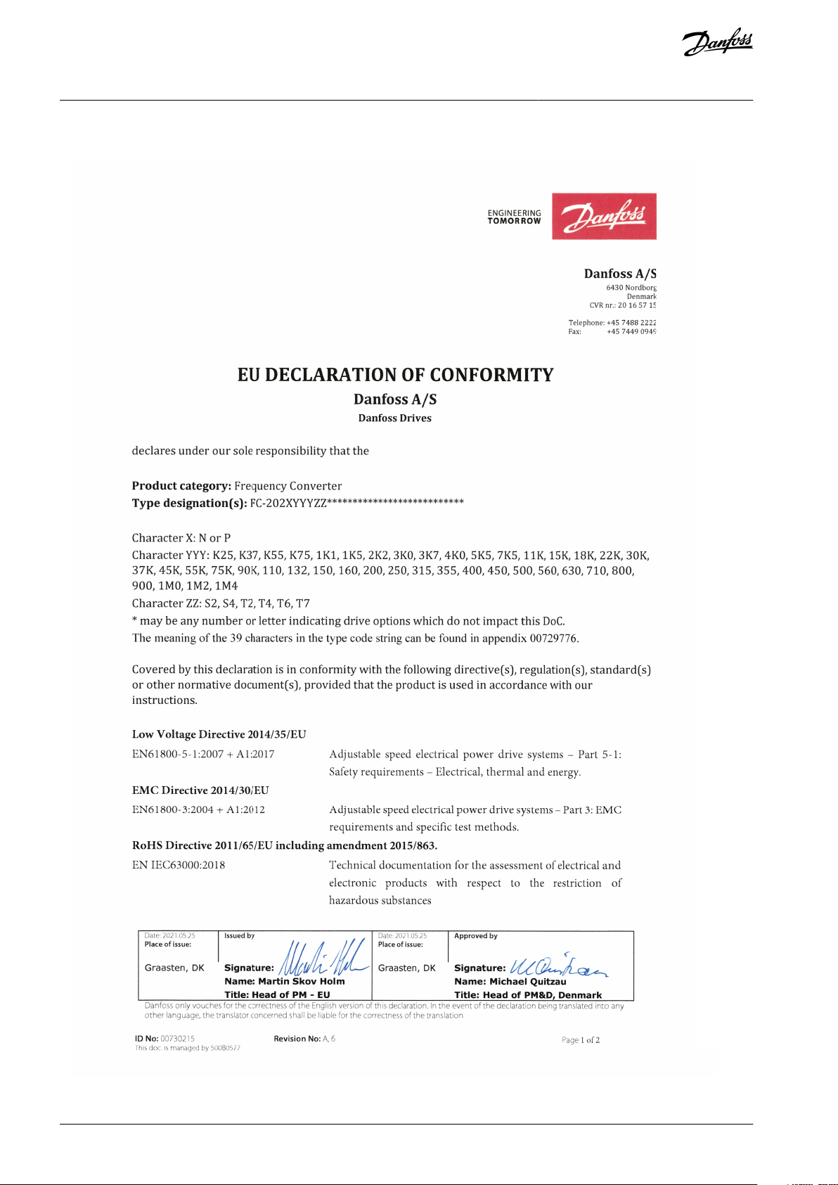
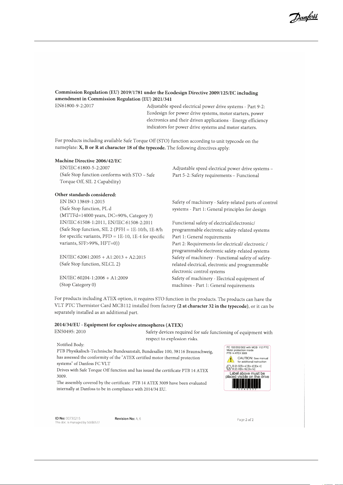
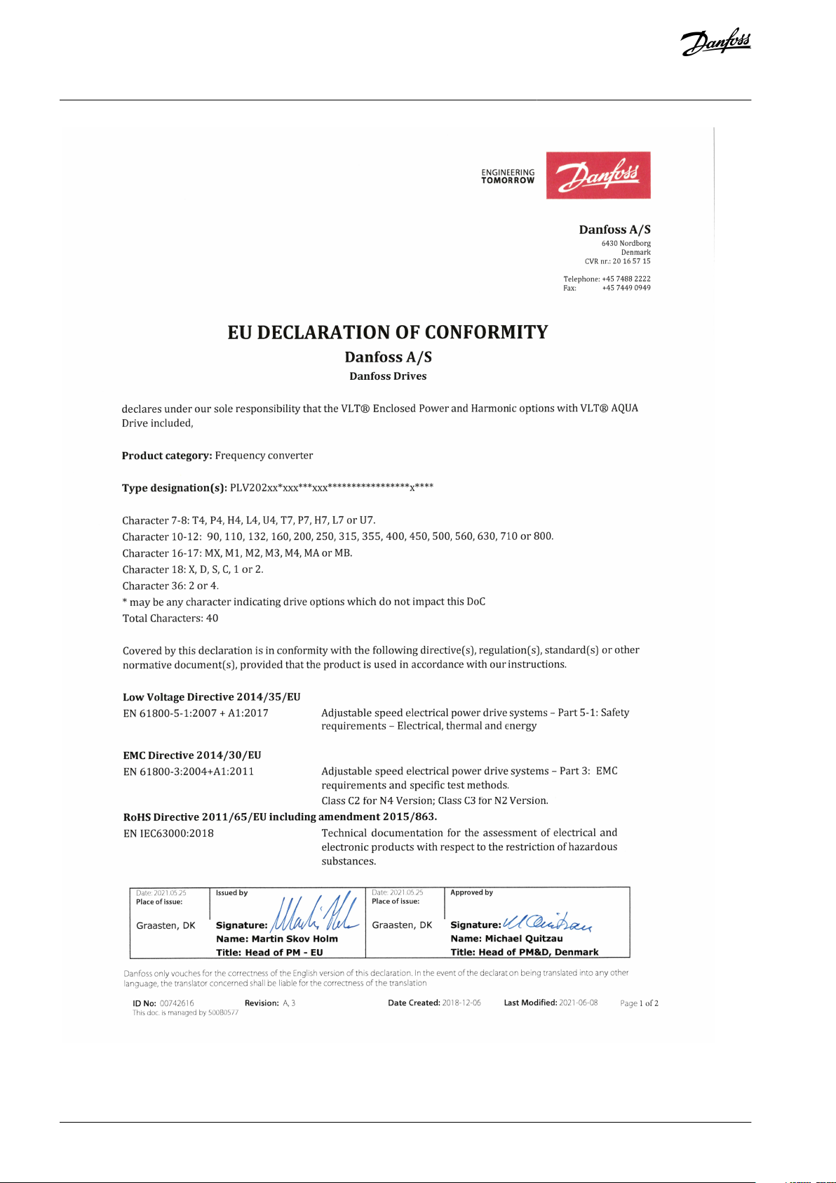
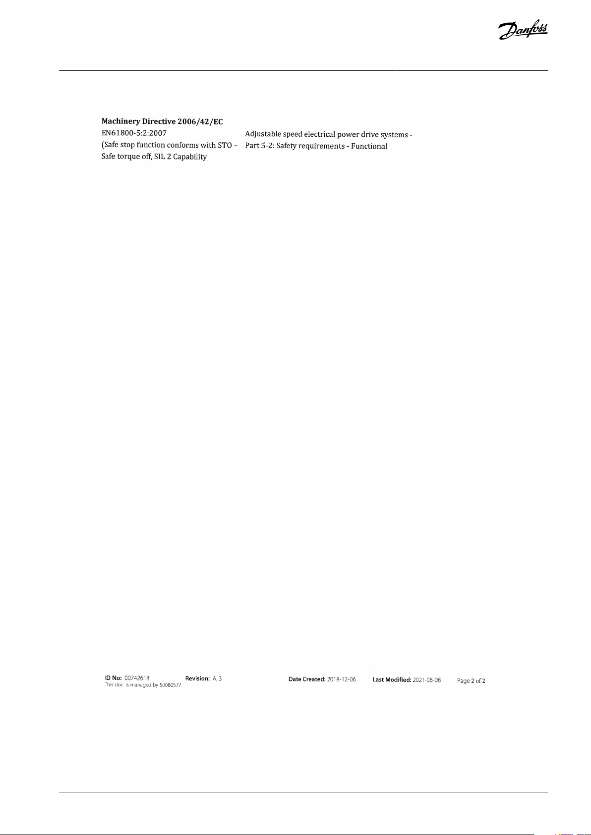
1.5 Finding the Declaration of Conformity Certificate
1.
Open a web browser and enter https://www.danfoss.com/en/service-and-support/documentation/.
2.
Click Certificates & declarations.
3.
Use the Search field to search for PLV*.
The system provides a list of the search results.
Filter the search results be entering the following criteria.
4.
a.
Business unit = Drives
b.
Documents/Document types = Certificate
5.
Scroll down until you find the PLV XXX titled certificate for the specific product segment, such as PLV 202 EU Declaration.
Double click the link to the open the certificate. For an example, see
1.6 Declaration of Conformity Certificate.
AQ262141056213en-000201 / 130R0882 | 9Danfoss A/S © 2021.11
VLT® AQUA Drive FC 202
Operating Guide
1.6 Declaration of Conformity Certificate
Introduction
AQ262141056213en-000201 / 130R088210 | Danfoss A/S © 2021.11
VLT® AQUA Drive FC 202
Operating Guide
Introduction
AQ262141056213en-000201 / 130R0882 | 11Danfoss A/S © 2021.11
VLT® AQUA Drive FC 202
Operating Guide
Introduction
AQ262141056213en-000201 / 130R088212 | Danfoss A/S © 2021.11
VLT® AQUA Drive FC 202
Operating Guide
Introduction
AQ262141056213en-000201 / 130R0882 | 13Danfoss A/S © 2021.11
VLT® AQUA Drive FC 202
Operating Guide
2 Safety
2.1 Safety Symbols
The following symbols are used in this manual:
D A N G E R
Indicates a hazardous situation which, if not avoided, will result in death or serious injury.
W A R N I N G
Indicates a hazardous situation which, if not avoided, could result in death or serious injury.
C A U T I O N
Indicates a hazardous situation which, if not avoided, could result in minor or moderate injury.
N O T I C E
Indicates information considered important, but not hazard-related (for example, messages relating to property damage).
Safety
2.2 Qualified Personnel
To allow trouble-free and safe operation of the unit, only qualified personnel with proven skills are allowed to transport, store, assemble, install, program, commission, maintain, and decommission this equipment.
Persons with proven skills:
•
Are qualified electrical engineers, or persons who have received training from qualified electrical engineers and are suitably
experienced to operate devices, systems, plant, and machinery in accordance with pertinent laws and regulations.
•
Are familiar with the basic regulations concerning health and safety/accident prevention.
•
Have read and understood the safety guidelines given in all manuals provided with the unit, especially the instructions given in
the Operating Guide.
•
Have good knowledge of the generic and specialist standards applicable to the specific application.
AQ262141056213en-000201 / 130R088214 | Danfoss A/S © 2021.11
Drive model
Minimum waiting time
D9h/D10h
20 minutes
E5h/E6h
40 minutes
VLT® AQUA Drive FC 202
Operating Guide
Safety
2.3 Safety Precautions
W A R N I N G
LACK OF SAFETY AWARENESS
This document gives important information on how to prevent injury and damage to the equipment or the system. Ignoring
them can lead to death, serious injury, or severe damage to the equipment.
Make sure to fully understand the dangers and safety measures incurred in the application.
-
W A R N I N G
DISCHARGE TIME
The drive contains DC-link capacitors and, if input filter options are present, extra capacitors and inductors. These components
can remain charged even when the drive is not powered. High voltage can be present even when the warning indicator lights are
off.
Failure to wait the specified time after power has been removed before performing service or repair work could result in death or
serious injury.
Stop the motor.
-
Disconnect AC mains, permanent magnet type motors, and remote DC-link supplies, including battery back-ups, UPS, and
-
DC-link connections to other drives.
Wait for the capacitors to discharge fully. The minimum waiting time is specified both in the Discharge Time table and on the
-
nameplate on top of the drive.
Before performing any service or repair work, use an appropriate voltage measuring device to make sure that the capacitors
-
are fully discharged.
Table 2: Discharge Time
W A R N I N G
HIGH VOLTAGE
AC drives contain high voltage when connected to AC mains input. Failure to perform installation , start-up, and maintenance by
qualified personnel can result in death or serious injury.
Only qualified personnel must perform installation, start-up, and maintenance.
-
W A R N I N G
UNINTENDED START
When the drive is connected to the AC mains, DC supply, or load sharing, the motor may start at any time, causing risk of death,
serious injury, and equipment or property damage. The motor may start by activation of an external switch, a fieldbus command,
an input reference signal from the LCP or LOP, via remote operation using MCT 10 Set-up software, or after a cleared fault condi-
tion.
Press [Off] on the LCP before programming parameters.
-
Disconnect the drive from the mains whenever personal safety considerations make it necessary to avoid unintended motor
-
start.
Check that the drive, motor, and any driven equipment are in operational readiness.
-
AQ262141056213en-000201 / 130R0882 | 15Danfoss A/S © 2021.11
VLT® AQUA Drive FC 202
Operating Guide
W A R N I N G
LEAKAGE CURRENT HAZARD
Leakage currents exceed 3.5 mA. Failure to ground the drive properly can result in death or serious injury.
Ensure the correct grounding of the equipment by a certified electrical installer.
-
W A R N I N G
ROTATING SHAFTS
Contact with rotating shafts and electrical equipment can result in death or serious injury.
Ensure that only trained and qualified personnel perform installation, start-up, and maintenance.
-
Ensure that electrical work conforms to national and local electrical codes.
-
Follow the procedures in this guide.
-
C A U T I O N
INTERNAL FAILURE HAZARD
An internal failure in the drive can result in serious injury when the drive is not properly closed.
Ensure that all safety covers are in place and securely fastened before applying power.
-
Safety
AQ262141056213en-000201 / 130R088216 | Danfoss A/S © 2021.11

VLT® AQUA Drive FC 202
Operating Guide
Product Overview
3 Product Overview
3.1 Intended Use
N O T I C E
OUTPUT FREQUENCY LIMIT
Due to export control regulations, the output frequency of the drive is limited to 590 Hz. For demands exceeding 590 Hz, contact
Danfoss.
The enclosed drive is an electronic motor controller that converts AC mains input into a variable AC waveform output. The frequency and voltage of the output are regulated to control the motor speed or torque. Depending on the configuration, the drive can be
used in standalone applications or form part of a larger system or installation. The enclosed drive is designed to:
•
Regulate motor speed in response to system feedback or remote commands from external controllers.
•
Provide motor overload protection.
•
Monitor system and motor status.
•
Reduce harmonics and increase the power factor using the optional passive harmonic filter or line reactor.
•
Reduce motor acoustic noise and protect motor insulation with the optional output filters.
•
Reduce bearing current and shaft voltage with the optional common-mode filter.
•
Reduce high-frequency, electromagnetic noise in the motor cables with the optional dU/dt filter.
•
Provide sinusoidal output with optional sine-wave filter.
The enclosed drive is designed for residential, industrial, and commercial environments in accordance with local laws and standards. Do not use this drive in applications that are non-compliant with specified operating conditions and environments.
N O T I C E
RADIO INTERFERENCE
In a residential environment, this product can cause radio interference.
Take supplementary mitigation measures.
-
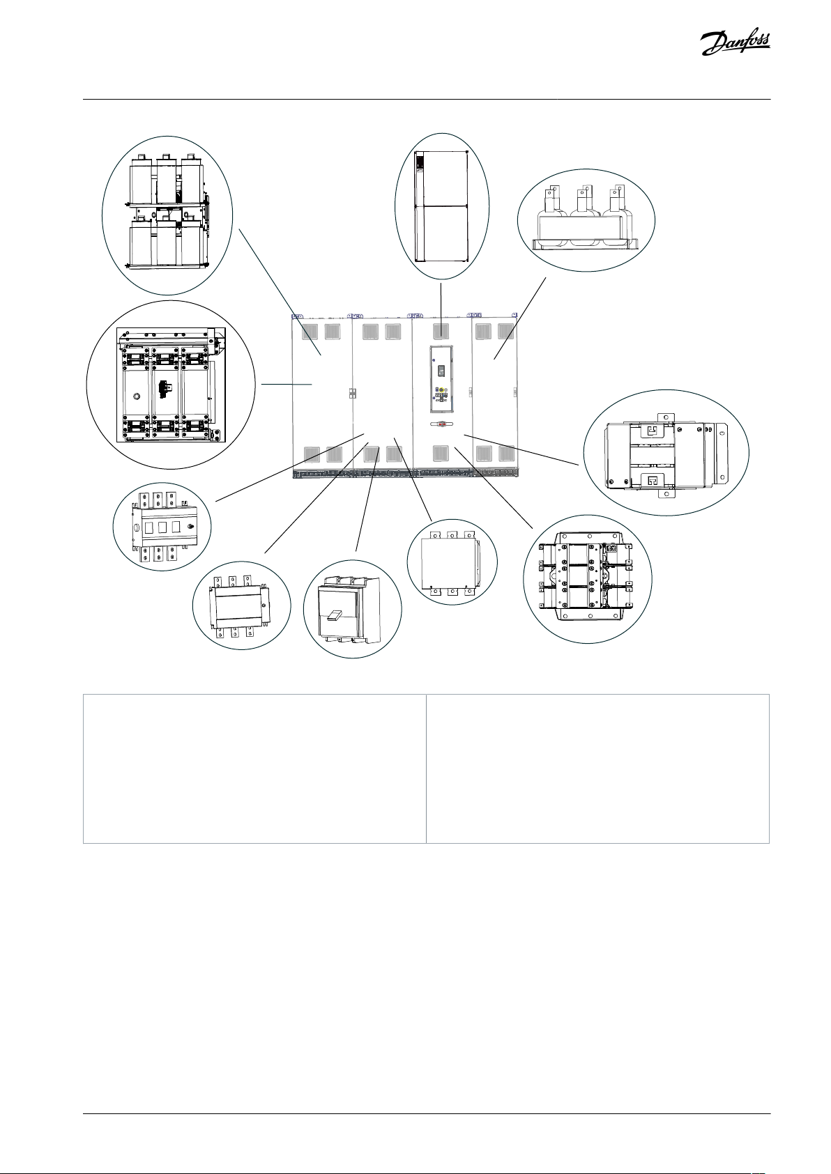
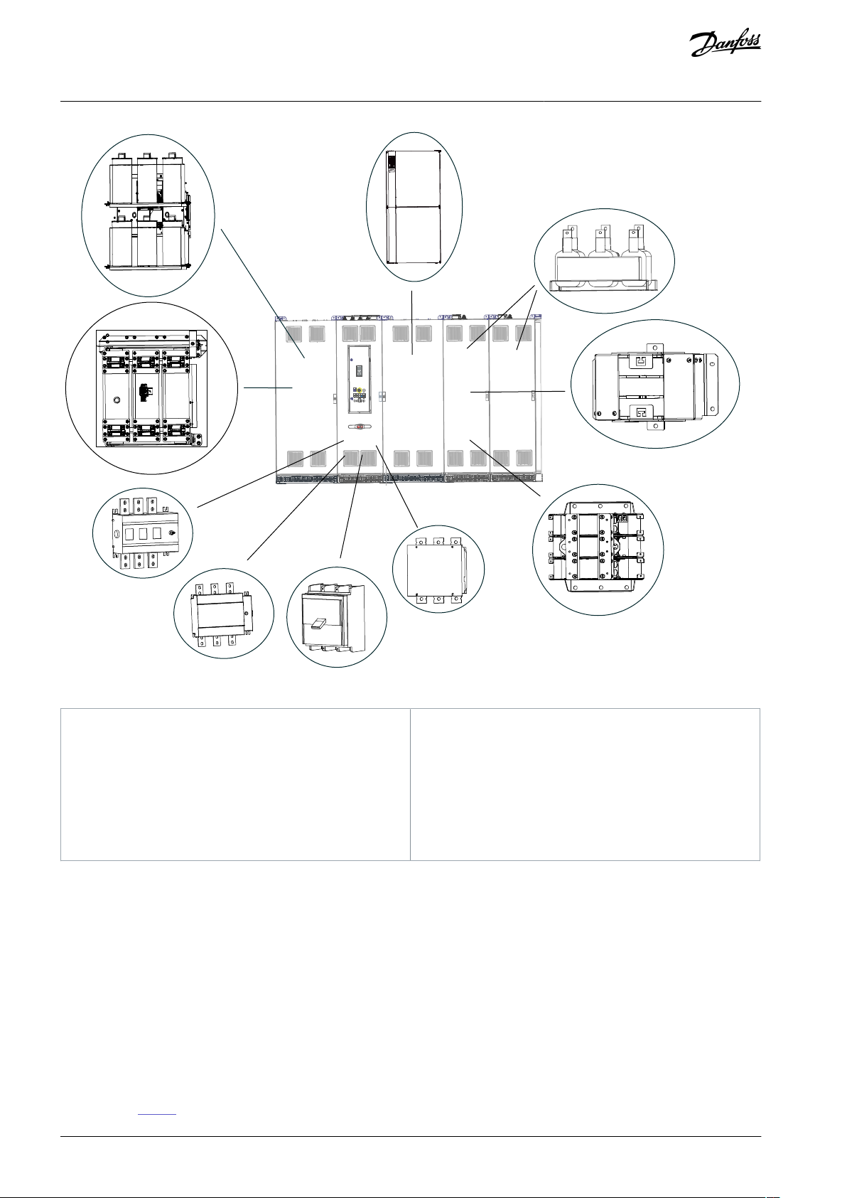
3.2 What is an Enclosed Drive?
The enclosed drive is an IP21/54 (NEMA 1/12) enclosure surrounding an IP20 (Protected Chassis) drive to form the basis of the system. There are 4 enclosed drive models with varying power ratings.
•
D9h model: 110–160 kW (125–250 hp)
•
D10h model: 200–400 kW (250–450 hp)
•
E5h model: 355–630 kW (450–650 hp)
•
E6h model: 500–800 kW (650–950 hp)
The enclosed drive is available with various power options and input and output filters to create a factory-built, custom drive. Some
options and filters result in extra cabinets attached to the left or right side of the drive cabinet. These optional cabinets are shown
with dotted lines, while the drive cabinet is shaded.
AQ262141056213en-000201 / 130R0882 | 17Danfoss A/S © 2021.11
e30bu152.10
1
3
2
4
5
1
Input filter cabinet (passive harmonic filter or line reactor)
2
Drives cabinet
3
Sine-wave cabinet
4
Control compartment
5
Input power options
(1)
e30bu067.10
1
2
4
5
3
1
Input filter cabinet (passive harmonic filter or line reactor)
2
Input power options cabinet
(1)
3
Drive cabinet
4
Sine-wave filter cabinet
5
Control compartment
VLT® AQUA Drive FC 202
Operating Guide
Illustration 1: Possible Configurations for a D9h Enclosed Drive
Product Overview
1
The D9h enclosure does not require an input power options cabinet – the input power options are placed in the drive cabinet.
Illustration 2: Possible Configurations for a D10h Enclosed Drive
1
If more than 1 input power option is ordered, the D10h enclosed drive requires an input power options cabinet. Otherwise the single input power
option is placed below the control compartment in the drive cabinet.
AQ262141056213en-000201 / 130R088218 | Danfoss A/S © 2021.11
e30bu068.10
1
2
4
3
6
5
3
1
Input filter cabinet (passive harmonic filter or line reactor)
2
Input power options cabinet
3
Drive cabinet
4
Sine-wave filter cabinet
5
Control compartment
6
dU/dt filter cabinet
VLT® AQUA Drive FC 202
Operating Guide
Illustration 3: Possible Configurations for an E5h or E6h Enclosed Drive
Product Overview
AQ262141056213en-000201 / 130R0882 | 19Danfoss A/S © 2021.11
e30bu177.11
1
2
3
4
5
6
7
8
9
10
1
Passive harmonic filter (PHF)
2
Line reactor
3
Non-fusible disconnect
4
Fusible disconnect
5
Molded-case circuit breaker (MCCB)
6
Mains contactor
7
dU/dt filter
8
Common-mode filter
9
Sine-wave filter
10
Drive module (varies in power rating)
VLT® AQUA Drive FC 202
Operating Guide
3.3 Location of Options within an Enclosed Drive
Product Overview
Illustration 4: Visual Representation of a D9h Enclosure and the Locations of Available Options
AQ262141056213en-000201 / 130R088220 | Danfoss A/S © 2021.11
e30bu178.12
1
2
3
4
5
6
7
8
9
10
1
Passive harmonic filter (PHF)
2
Line reactor
3
Non-fusible disconnect
4
Fusible disconnect
5
Molded-case circuit breaker (MCCB)
6
Mains contactor
7
dU/dt filter
8
Common-mode filter
9
Sine-wave filter
10
Drive module (varies in power rating)
VLT® AQUA Drive FC 202
Operating Guide
Product Overview
Illustration 5: Visual Representation of a D10h Enclosure and the Locations of Available Options
AQ262141056213en-000201 / 130R0882 | 21Danfoss A/S © 2021.11
e30bu141.12
1
2
3
4
5
6
7
8
9
10
1
Passive harmonic filter (PHF)
2
Line reactor
3
Non-fusible disconnect
4
Fusible disconnect
5
Molded-case circuit breaker (MCCB)
6
Mains contactor
7
dU/dt filter
8
Common-mode filter
9
Sine-wave filter
10
Drive module (varies in power rating)
VLT® AQUA Drive FC 202
Operating Guide
Product Overview
Illustration 6: Visual Representation of a E5h/E6h Enclosure and the Locations of Available Options
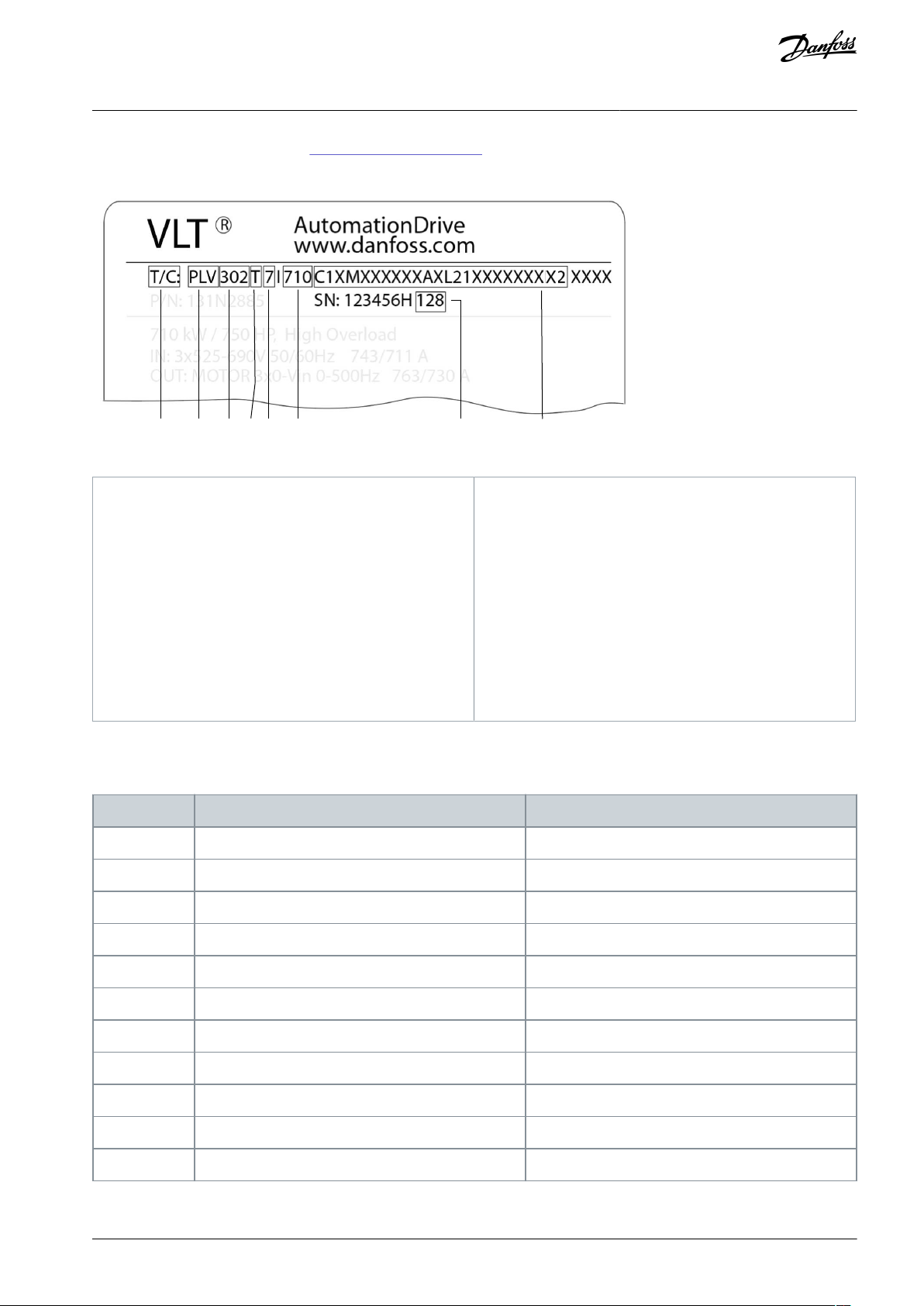
3.4 Drive Identification
3.4.1 Identifying the Drive and Its Options
Enclosure size and specific options are used throughout this guide whenever procedures or components differ based on the drive
and its options. Use the following steps to identify the enclosed drive:
Procedure
1.
Locate the type code (T/C) on the nameplate. The nameplate is found on the exterior of the drive by the bottom grill and
on the control compartment door.
2.
Determine the type of enclosure by obtaining the following information from the type code:
a.
Product group and drive series (characters 1–6).
b.
Voltage rating (character 8).
c.
Model/power rating (characters 10–12).
3.
Go to Table 3 and use the model number and voltage rating to find the enclosure size.
AQ262141056213en-000201 / 130R088222 | Danfoss A/S © 2021.11
•
•
•
•
•
•
•
e30bu139.11
1 2 3 4 5 6 7 8
1
Type code
2
Product group (PLV = enclosed drive)
3
Drive series
102 = VLT® HVAC Drive
103 = VLT® Refrigeration Drive
202 = VLT® AQUA Drive
302 = VLT® AutomationDrive
4
Low harmonic filter option (if any)
5
Mains voltage
4 = 380–480 V
5 = 380–500 V
7 = 525–690 V
6
Model/power rating
7
Build date (wwy, where ww = the week and y = the
last digit of the year)
8
Option codes
Model
Enclosure size (380–480 V)
Enclosure size (525–690 V)
N110
D9h
D9h
N132
D9h
D9h
N160
D9h
D9h
N200
D10h
D10h
N250
D10h
D10h
N315
D10h
D10h
N355
E5h–N400
E5h
D10h
N450
E5h
E5h
N500
E6h
E5h
N560
E6h
E5h
VLT® AQUA Drive FC 202
Operating Guide
4.
Using the type code, refer to 3.4.3 Type Code Identification to identify the installed options.
Example
Illustration 7: Using the Nameplate to Find the Enclosure Size and Installed Options
Product Overview
3.4.2 Enclosure Size Identification
Table 3: Model by Drive Voltage
AQ262141056213en-000201 / 130R0882 | 23Danfoss A/S © 2021.11
Model
Enclosure size (380–480 V)
Enclosure size (525–690 V)
N630–E5h
N710–E6h
N800–E6h
Character position
Code
Description
1–3
PLV
VLT® Enclosed Drives
Character position
Code
Description
4–6
102
VLT® HVAC Drive FC 102
103
VLT® Refrigeration Drive FC 103
202
VLT® AQUA Drive FC 202
302
VLT® AutomationDrive FC 302
Character position
Code
Description
7
T
None
P
Passive filter, THDi=5%, 50 Hz
H
Passive filter, THDi=8%, 50 Hz
L
Passive filter, THDi=5%, 60 Hz
U
Passive filter, THDi=8%, 60 Hz
Character position
Code
Description
8
4
380–480 V
5
380–500 V
7
525–690 V (525–600 V for UL)
Character position
Code
Description
9
I
IECUUL
VLT® AQUA Drive FC 202
Operating Guide
3.4.3 Type Code Identification
Table 4: Product Group Code
Table 5: Drive Series Codes
Product Overview
Table 6: Low-harmonic Filter Codes
Table 7: Mains Voltage Codes
Table 8: Norms and Standards Codes
AQ262141056213en-000201 / 130R088224 | Danfoss A/S © 2021.11
Character position
Code
Description
10–12
90K
(N90K) 90 kW/125 hp
110
(N110) 110 kW/150 hp
132
(N132) 132 kW/200 hp
160
(N160) 160 kW/250 hp
200
(N200) 200 kW/300 hp
250
(N250) 250 kW/350 hp
315
(N315) 315 kW/450 hp
355
(N355) 355 kW/500 hp
400
(N400) 400 kW/550 hp
450
(N450) 450 kW/600 hp
500
(N500) 500 kW/650 hp
560
(N560) 560 kW/750 hp
630
(N639) 630 kW/900 hp
710
(N710) 710 kW/1000 hp
800
(N800) 800 kW/1200 hp
Character position
Code
Description
13
C
Coated PCB
R
Coated PCB + ruggedized
Character position
Code
Description
14
1
100 mm high pedestal
2
200 mm high pedestal
4
400 mm high pedestal
5
Marine pedestal
Character position
Code
Description
15
X
No brake IGBT
B
Brake IGBT
T
Safe Torque Off
U
Brake IGBT + Safe Torque Off
VLT® AQUA Drive FC 202
Operating Guide
Table 9: Power Rating Codes
Product Overview
Table 10: Drive Module PCB Coating Codes
Table 11: Plinth (Pedestal) Codes
Table 12: Drive Module Braking and Safety Codes
AQ262141056213en-000201 / 130R0882 | 25Danfoss A/S © 2021.11
Character position
Code
Description
16–17
MX
None
M1
Fusible disconnect
M2
Non-fusible disconnect
M3
Circuit breaker (MCCB)
M4
Mains contactor
M5
AC reactor
M6
Fuses
MA
Fusible disconnect + mains contactor
MB
Non-fusible disconnect + mains contactor
MC
AC reactor + fusible disconnect
MD
AC reactor + fusible disconnect + mains contactor
ME
AC reactor + non-fusible disconnect
MF
AC reactor + circuit breaker (MCCB)
MG
AC reactor + mains contactor
MH
AC reactor + non-fusible disconnect + mains contactor
Character position
Code
Description
18
X
None
D
dU/dt filter
S
Sine-wave filter
C
Common-mode filter
1
Common-mode + dU/dt filters
2
Common-mode + sine-wave filters
Character position
Code
Description
19XNone
VLT® AQUA Drive FC 202
Operating Guide
Table 13: Mains Option Codes
Product Overview
Table 14: Output Filter Codes
Table 15: Reserved Code
AQ262141056213en-000201 / 130R088226 | Danfoss A/S © 2021.11
Character position
Code
Description
20
X
Bottom
T
TopLMains top, motor bottom
M
Mains bottom, motor top
Character position
Code
Description
21
1
230 V AC external
2
230 V AC internal
4
230 V AC internal + 24 V DC internal
5
230 V AC external + 24 V DC internal
6
120 V AC external
7
120 V AC internal
8
120 V AC internal + 24 V DC internal
9
120 V AC external + 24 V DC internal
Character position
Code
Description
22
X
Bottom in, top out
1
Back in, back out
C
Back in, top out
D
Bottom in, back out
N
None
Character position
Code
Description
23–24
AX
No auxiliary options
A1
AC socket+cabinet light
A2
Extended I/O terminals
A3
Cabinet heater
A4
Motor heater control
A5
Insulation monitor
AA
AC socket + cabinet light + extended I/O terminals
AB
AC socket + cabinet light + cabinet heater
VLT® AQUA Drive FC 202
Operating Guide
Table 16: Cable Infeed Codes
Table 17: Auxiliary Power Supply Codes
Product Overview
Table 18: Back-channel Cooling Codes
Table 19: Auxiliary Function Codes
AQ262141056213en-000201 / 130R0882 | 27Danfoss A/S © 2021.11
Character position
Code
Description
AC
AC socket + cabinet light + motor heater control
AD
AC socket + cabinet light + insulation monitor
AE
AC socket + cabinet light + extended I/O terminals + cabinet heater
AF
AC socket + cabinet light + extended I/O terminals + motor heater control
AG
AC socket + cabinet light + extended I/O terminals + insulation monitor
AH
AC socket + cabinet light + extended I/O terminals + cabinet heater + motor heater control
AI
AC socket + cabinet light + extended I/O terminals + cabinet heater + insulation monitor
AJ
AC socket + cabinet light + extended I/O terminals + motor heater control + insulation monitor
AK
AC socket + cabinet light + extended I/O terminals + cabinet heater + motor heater control + insulation monitor
AL
AC socket + cabinet light + cabinet heater + motor heater control
AM
AC socket + cabinet light + cabinet heater + insulation monitor
AN
AC socket + cabinet light + cabinet heater + motor heater control + insulation monitor
AO
AC socket + cabinet light + motor heater control + insulation monitor
AP
Extended I/O terminals + cabinet heater
AQ
Extended I/O terminals + motor heater control
AR
Extended I/O terminals + insulation monitor
AS
Extended I/O terminals + cabinet heater + motor heater control
AT
Extended I/O terminals + cabinet heater + insulation monitor
AU
Extended I/O terminals + cabinet heater + motor heater control + insulation monitor
AV
Extended I/O terminals + motor heater control + insulation monitor
AW
Cabinet heater + motor heater control
A8
Cabinet heater + insulation monitor
AY
Cabinet heater + motor heater control + insulation monitor
AZ
Motor heater control + insulation monitor
Character position
Code
Description
25
L
LCP in the door
N
No LCP in the door
VLT® AQUA Drive FC 202
Operating Guide
Product Overview
Table 20: LCP Mounting Codes
AQ262141056213en-000201 / 130R088228 | Danfoss A/S © 2021.11
Character position
Code
Description
26–27
21
IP2154IP54
Character position
Code
Description
28–29
XX
None
D1
Signal lights and reset button
D2
Emergency switch off + emergency push-button
D3
STO with emergency push-button (basic functional safety)
D4
STO/SS1 with emergency push-button + safely limited speed (TTL encoder)
D5
STO/SS1 with emergency push-button + safely limited speed (HTL encoder)
DA
Indicator lights and reset button + emergency switch off and emergency push-button
DB
Indicator lights and reset button + STO with emergency push-button (basic functional safety)
DC
Indicator lights and reset button + STO/SS1 with emergency push-button + safely limited speed
(TTL encoder)
DE
Indicator lights and reset button + STO/SS1 with emergency push-button + safely limited speed
(HTL encoder)
Character position
Code
Description
30
X
No A option
0
VLT® PROFIBUS DP-V1 MCA 101
4
VLT® DeviceNet MCA 104 (FC 102/FC 202/FC 302 only)
6
VLT® CANopen MCA 105 (FC 302 only)
8
VLT® EtherCAT MCA 124 (FC 302 only)
G
VLT® LonWorks MCA 108 (FC 102 only)
J
VLT® BACnet MCA 109 (FC 102 only)
K
VLT® BACnet/IP MCA 125 (FC 102 only)
L
VLT® PROFINET MCA 120
N
VLT® EtherNet/IP MCA 121 (FC 102/FC 202/FC 302 only)
Q
VLT® Modbus TCP MCA 122 (FC 102/FC 202/FC 302 only)
T
VLT® PROFIBUS Converter VLT 3000 MCA 113 (FC 302 only)
U
VLT® PROFIBUS Converter VLT 5000 MCA 114 (FC 302 only)
VLT® AQUA Drive FC 202
Operating Guide
Table 21: Protection Rating Codes
Table 22: Door-mounted Codes
Product Overview
Table 23: A Option Codes
AQ262141056213en-000201 / 130R0882 | 29Danfoss A/S © 2021.11
Character position
Code
Description
Y
VLT® POWERLINK MCA 123 (FC 302 only)
W
VLT® DeviceNet Converter MCA 194 (FC 302 only)
Z
VLT® AK-LonWorks MCA 107 (FC 103 only)
Character position
Code
Description
31
X
No B option
0
VLT® Analog I/O MCB 109 (FC 102/FC 103/FC 202 only)
2
VLT® PTC Thermistor Card MCB 112 (FC 102/FC 202/FC 302 only)
4
VLT® Sensor Input MCB 114 (FC 102/FC 202/FC 302 only)
K
VLT® General Purpose I/O Option MCB 101
P
VLT® Relay Option MCB 105
Y
VLT® Extended Cascade Controller MCO 101 (FC 202 only)
R
VLT® Encoder Option MCB 102 (FC 302 only)
U
VLT® Resolver Option MCB 103 (FC 302 only)
Z
VLT® Safety PLC Interface MCB 108 (FC 302 only)
5
VLT® Programmable I/O MCB 115
6
VLT® Safe Option TTL MCB 150 (FC 302 only)
7
VLT® Safe Option HTL MCB 151 (FC 302 only)
8
VLT® Safety Option MCB 152 (FC 302 only)
Character position
Code
Description
32
X
No C option software
4
VLT® Motion Control MCO 305 (FC 302 only)
Character position
Code
Description
33
X
No C1 option
5
VLT® Advanced Cascade Controller MCO 102 (FC 202/FC 302 only)
7
VLT® Sensorless Safety MCB 159 (FC 302 only)
R
VLT® Extended Relay Card MCB 113 (FC 302 only)
VLT® AQUA Drive FC 202
Operating Guide
Table 24: B Option Codes
Product Overview
Table 25: C0 Option MCO Codes
Table 26: C1 Option Codes
AQ262141056213en-000201 / 130R088230 | Danfoss A/S © 2021.11

Character position
Code
Description
34
X
No software option
0
VLT® Synchronizing Controller MCO 350 (FC 302 only)
1
VLT® Positioning Controller MCO 351 (FC 302 only)
Character position
Code
Description
35
X
No D option
0
VLT® 24 V DC Supply MCB 107
1
VLT® Real time clock option MCB 117
Character position
Code
Description
36
2
(H2) RFI class A2 (C3)
4
(H4) RFI class A1 (C2)
Character position
Code
Description
37–39
X
None
Character position
Code
Description
40
X
English, no 2nd language
G
English + German
F
English + French
Enclosed drive
D9h
D10h
E5h
E6h
Rated power at 380–480 V [kW
(hp)]
110–160 (150–250)
200–315 (300–450)
355–450 (500–600)
500–560 (650–750)
Rated power at 525–690 V [kW
(hp)]
110–160 (125–200)
200–400 (250–400)
450–630 (450–650)
710–800 (750–950)
Protection rating
IP21 (NEMA 1)/
IP54 (NEMA 12)
IP21 (NEMA 1)/IP54
(NEMA 12)
IP21 (NEMA 1)/IP54
(NEMA 12)
IP21 (NEMA 1)/IP54
(NEMA 12)
Drive cabinet
D9h
D10h
E5h
E6h
Height [mm (in)]
(1)
2100 (82.7)
2100 (82.7)
2100 (82.7)
2100 (82.7)
Width [mm (in)]
(2)
400 (15.8)
600 (23.6)
600 (23.6)
800 (31.5)
VLT® AQUA Drive FC 202
Operating Guide
Table 27: C Option Software Codes
Table 28: D Option Codes
Table 29: EMC Filter Codes
Product Overview
Table 30: Reserved Code
Table 31: Documentation Language Codes
3.5 Power Ratings, Weight, and Dimensions
Table 32: Power Ratings and Dimensions for D9h–D10h and E5h–E6h Enclosures (Standard Configurations)
AQ262141056213en-000201 / 130R0882 | 31Danfoss A/S © 2021.11

Enclosed drive
D9h
D10h
E5h
E6h
Depth [mm (in)]
600 (23.6)
600 (23.6)
600 (23.6)
600 (23.6)
Weight [kg (lb)]
(2)
280 (617)
355 (783)
400 (882)
431 (950)
Input filter cabinet
D9h
D10h
E5h
E6h
Height [mm (in)]
(1)
2100 (82.7)
2100 (82.7)
2100 (82.7)
2100 (82.7)
Width [mm (in)]
400 (15.8)/600
(23.6)
400 (15.8)/600
(23.6)
600 (23.6)/800 (31.5)
600 (23.6)/800 (31.5)
Depth [mm (in)]
600 (23.6)
600 (23.6)
600 (23.6)
600 (23.6)
Weight [kg (lb)]
410 (904)
410 (904)/530
(1168)
530 (1168)
530 (1168)/955
(2105)
Input power options cabinet
D9h
D10h
E5h
E6h
Height [mm (in)]
(1)
–
2100 (82.7)
2100 (82.7)
2100 (82.7)
Width [mm (in)]
–
600 (23.6)
600 (23.6)
600 (23.6)
Depth [mm (in)]
–
600 (23.6)
600 (23.6)
600 (23.6)
Weight [kg (lb)]
–
380 (838)
380 (838)
380 (838)
Sine-wave filter cabinet
D9h
D10h
E5h
E6h
Height [mm (in)]
(1)
2100 (82.7)
2100 (82.7)
2100 (82.7)
2100 (82.7)
Width [mm (in)]
600 (23.6)
600 (23.6)
1200 (47.2)
1200 (47.2)
Depth [mm (in)]
600 (23.6)
600 (23.6)
600 (23.6)
600 (23.6)
Weight [kg (lb)]
384 (847)
384 (847)
768 (1693)
768 (1693)
dU/dt filter cabinet
D9h
D10h
E5h
E6h
Height [mm (in)]
(1)
––2100 (82.7)
2100 (82.7)
Width [mm (in)]
(3)
––400 (15.8)
400 (15.8)
Depth [mm (in)]
––600 (23.6)
600 (23.6)
Weight [kg (lb)]
––240 (529)
240 (529)
Top entry/exit cabinet
D9h
D10h
E5h
E6h
Height [mm (in)]
(1)
2100 (82.7)
2100 (82.7)
2100 (82.7)
2100 (82.7)
Width [mm (in)]
(3)
400 (15.8)
400 (15.8)
400 (15.8)
400 (15.8)
Depth [mm (in)]
600 (23.6)
600 (23.6)
600 (23.6)
600 (23.6)
Weight [kg (lb)]
164 (362)
164 (362)
164 (362)
164 (362)
VLT® AQUA Drive FC 202
Operating Guide
Product Overview
1
Cabinet height includes standard 100 mm (3.9 in) pedestal. A 200 mm (7.9 in) or 400 mm (15.8 in) pedestal is optional.
2
Without options.
3
The E5h and E6h enclosures contain 2 sine-wave cabinets. The provided width is the total of both cabinets.
AQ262141056213en-000201 / 130R088232 | Danfoss A/S © 2021.11

VLT® AQUA Drive FC 202
Operating Guide
Product Overview
3.6 Control Compartment and Local Control Panel
3.6.1 Control Compartment Overview
The control compartment is a self-contained space that can be accessed without opening the drive enclosure. The control compartment contains the following:
•
Control terminals.
•
Relay terminals.
•
Terminals for option cards.
•
Optional components:
-
Auxiliary supply terminals.
-
Auxiliary voltage transformer connections.
-
+24 V DC external supply.
-
AC customer socket.
-
Extended I/O terminals.
-
Cabinet heater connections.
-
Motor heater control connections.
-
Thermal trip indicator relays.
-
Insulation monitor.
-
Magnetic cabinet light.
•
Buttons and indicator lights (on the exterior door).
•
Local control panel (LCP).
•
Product nameplate.
AQ262141056213en-000201 / 130R0882 | 33Danfoss A/S © 2021.11

e30bu142.11
4
6
7
8
5
3
2
1
9
1
Local control panel (LCP)
2
Emergency push-button
3
Fault indicator light
4
Run indicator light
5
Insulation fault indicator light
6
USB slot
7
0–1 Start switch
8
Reset button
9
Nameplate
VLT® AQUA Drive FC 202
Operating Guide
3.6.2 Control Compartment Door
Product Overview
Illustration 8: Exterior Door of Control Compartment (Shown with All Options)
AQ262141056213en-000201 / 130R088234 | Danfoss A/S © 2021.11

e30bf155.10
Auto
On
Reset
Hand
On
Off
Status
Quick
Menu
Main
Menu
Alarm
Log
Back
Cancel
Info
OK
Status
1(1)
0.00 kW
Off Remote Stop
0.0 Hz
On
Alarm
Warn.
0.00 A
0 RPM
0.0 %
A1.1
A1.2
A1.3
A2
A3
B1
B2
B4
B3
C1
C2
C3
C4
C5
D1
D2
D3
E1
E2
E3
E4
Callout
Parameter
Default setting
A1.1
Parameter 0-20 Display Line 1.1 Small
Reference [Unit]
A1.2
Parameter 0-21 Display Line 1.2 Small
Analog input 53 [V]
A1.3
Parameter 0-22 Display Line 1.3 Small
Motor current [A]
A2
Parameter 0-23 Display Line 2 Large
Frequency [Hz]
A3
Parameter 0-24 Display Line 3 Large
Feedback [Unit]
VLT® AQUA Drive FC 202
Operating Guide
3.6.3 Local Control Panel (LCP)
Product Overview
Illustration 9: Graphical Local Control Panel (LCP)
The local control panel (LCP) is the combined display and keypad on the front of the drive. The LCP is used to:
•
Control the drive and motor.
•
Access drive parameters and program the drive.
•
Show operational data, drive status, and warnings.
A numeric local control panel (NLCP) is available as an option. The NLCP operates in a manner similar to the LCP, but there are
differences. For details on how to use the NLCP, see the product-specific Programming Guide.
A. Display area
Each display readout has a parameter associated with it. The information shown on the LCP can be customized for specific applications. Refer to My Personal Menu in the LCP Menu section.
Table 33: LCP Display Area
B. Menu keys
Menu keys are used to access the menu for setting up parameters, toggling through status display modes during normal operation,
and viewing fault log data.
AQ262141056213en-000201 / 130R0882 | 35Danfoss A/S © 2021.11
Callout
Key
Function
B1
Status
Shows operational information.
B2
Quick Menu
Allows access to parameters for initial set-up instructions. Also provides detailed application steps. Refer
to Quick Menu mode in the LCP Menu section.
B3
Main Menu
Allows access to all parameters. Refer to Main Menu mode in the LCP Menu section.
B4
Alarm Log
Shows a list of current warnings and the last 10 alarms.
Callout
Key
Function
C1
Back
Reverts to the previous step or list in the menu structure.
C2
Cancel
Cancels the last change or command as long as the display mode has not changed.
C3
Info
Shows a definition of the function being shown.
C4OKAccesses parameter groups or enables an option.
C5
[▵][▹] [▿] [◃]
Moves between items in the menu.
Callout
Indicator
LED
Function
D1OnGreen
Activates when the drive receives power from the mains voltage or a 24 V external supply.
D2
Warn.
Yellow
Activates when warning conditions are active. Text appears in the display area identifying the
problem.
D3
Alarm
Red
Activates during a fault condition. Text appears in the display area identifying the problem.
Callout
Key
Function
E1
[Hand On]
Starts the drive in local control. An external stop signal by control input or serial communication overrides
the local [Hand On].
E2
Off
Stops the motor but does not remove power to the drive.
E3
Reset
Resets the drive manually after a fault has been cleared.
E4
Auto On
Puts the system in remote operational mode so it can respond to an external start command by control
terminals or serial communication.
VLT® AQUA Drive FC 202
Operating Guide
Table 34: LCP Menu Keys
Product Overview
C. Navigation keys
Navigation keys are used for programming functions and moving the display cursor. The navigation keys also provide speed control
in local (hand) operation. The display brightness can be adjusted by pressing [Status] and [▵]/[▿] keys.
Table 35: LCP Navigation Keys
D. Indicator lights
Indicator lights identify the drive status and provide a visual notification of warning or fault conditions.
Table 36: LCP Indicator Lights
E. Operation keys and reset
The operation keys are found toward the bottom of the local control panel.
Table 37: LCP Operation Keys and Reset
AQ262141056213en-000201 / 130R088236 | Danfoss A/S © 2021.11
e30bf242.10
Q1 My Personal Menu
Q2 Quick Setup
Q3 Function Setups
Q5 Changes Made
0.0% 0.00
Quick Menus
1(1)
Q6 Loggings
Parameter 0-20 Display Line 1.1 Small
Reference [Unit]
Parameter 0-21 Display Line 1.2 Small
Analog input 53 [V]
Parameter 0-22 Display Line 1.3 Small
Motor current [A]
Parameter 0-23 Display Line 2 Large
Frequency [Hz]
Parameter 0-24 Display Line 3 Large
Feedback [Unit]
VLT® AQUA Drive FC 202
Operating Guide
Product Overview
3.6.4 LCP Menu
Quick Menus
The Quick Menus mode provides a list of menus used to configure and operate the drive. Select the Quick Menus mode by pressing
the [Quick Menu] key. The resulting readout appears on the LCP display.
Illustration 10: Quick Menu View
Q1 My Personal Menu
The Personal Menu is used to determine what is shown in the display area. Refer to 3.6.3 Local Control Panel (LCP). This menu can
also show up to 50 pre-programmed parameters. These 50 parameters are manually entered using parameter 0-25 My Personal
Menu.
Q2 Quick Setup
The parameters found in the Q2 Quick Setup contain basic system and motor data that are always necessary for configuring the
drive. See
Q3 Function Setups
The parameters found in the Q3 Function Setups contain data for fan, compressor, and pump functions. This menu also includes
parameters for LCP display, digital preset speeds, scaling of analog references, closed-loop single-zone, and multizone applications.
Q4 Smart Setup
Q4 Smart Setup guides the user through typical parameter settings used to configure 1 of the following 4 applications:
•
•
•
•
The [Info] key can be used to see help information for various selections, settings, and messages.
Q5 Changes Made
Select Q5 Changes Made for information about:
•
•
Q6 Loggings
Use Q6 Loggings for fault finding. To get information about the display line readout, select Loggings. The information is shown as
graphs. Only parameters selected in parameter 0-20 Display Line 1.1 Small through parameter 0-24 Display Line 3 Large can be viewed.
It is possible to store up to 120 samples in the memory for later reference.
7.2.4 Entering System Information for the set-up procedures.
Single pump/motor.
Motor alternation.
Master/follower.
Basic cascade.
The 10 most recent changes.
Changes made from default setting.
Table 38: Logging Parameter Examples
AQ262141056213en-000201 / 130R0882 | 37Danfoss A/S © 2021.11

e30bf204.10
O-** Operation / Display
1-** Load and Motor
2-** Brakes
3-** Reference / Ramps
0.0% 0.00 A
Main Menu
1(1)
VLT® AQUA Drive FC 202
Operating Guide
Q7 Water and Pumps
The parameters found in the Q7 Water and Pumps contain basic data that is necessary for configuring water pump applications.
Main Menu
The Main Menu mode is used to:
•
List the parameter groups available to the drive and drive options.
•
Change parameter values.
Illustration 11: Main Menu View
Product Overview
AQ262141056213en-000201 / 130R088238 | Danfoss A/S © 2021.11

e30bu138.11
1
2
3
4
5
6
e30bu764.11
1
Type code
2
Part number and serial number
3
Power rating
4
Input voltage, frequency, and current (at low/high
voltages)
5
Output voltage, frequency, and current (at low/high
voltages)
6
Discharge time
VLT® AQUA Drive FC 202
Operating Guide
Mechanical Installation
4 Mechanical Installation
4.1 Items Supplied
Items supplied can vary according to product configuration.
•
Make sure that the items supplied and the information on the nameplate correspond to the order confirmation.
•
Visually check the packaging and the drive for damage caused by inappropriate handling during shipment. File any claim for
damage with the carrier. Retain damaged parts for clarification.
Illustration 12: Example of a Product Nameplate for E6h Enclosure (IEC Version on Left, UL Version on Right)
WARRANTY
Removing the nameplate from the drive results in loss of warranty.
N O T I C E
4.2 Split Shipment
Depending on what options are ordered with an enclosed drive, the drive can consist of 5 cabinets and measure 3400 mm (134 in)
in width, which can be difficult to transport and handle. In cases where an enclosed drive exceeds 1800 mm (71 in) in width, the
cabinets are separated and shipped in multiple boxes. All necessary fasteners needed for reassembly are provided in the delivery.
To reassemble a split shipment, refer to 4.10 Combining Multiple Cabinets from a Split Shipment and 5.6.1 Connecting Wiring Har-
nesses.
AQ262141056213en-000201 / 130R0882 | 39Danfoss A/S © 2021.11

VLT® AQUA Drive FC 202
Operating Guide
Mechanical Installation
4.3 Tools Needed
•
I-beam and hooks rated to lift the weight of the drive.
•
Crane or other lifting aid to place the unit into position.
•
Drill with a 12 mm (1/2 in) drill bit.
•
Tape measurer.
•
Phillips and flat-bladed screwdrivers.
•
Wrench with 7–17 mm metric sockets.
•
Wrench extensions.
•
T25 and T50 Torx drives.
•
Sheet metal punch and/or pliers for cable entry plate.
4.4 Storing the Drive
Store the drive in a dry location. Keep the equipment sealed in its packaging until installation. Refer to the Ambient Conditions
section for recommended ambient temperature.
Periodic forming (capacitor charging) is not necessary during storage unless storage exceeds 12 months.
4.5 Operating Environment
4.5.1 Overview
In environments with airborne liquids, particles, or corrosive gases, ensure that the IP/NEMA protection rating of the equipment
matches the installation environment. Refer to the Ambient Conditions section.
N O T I C E
CONDENSATION
Moisture can condense on the electronic components and cause short circuits.
Avoid installation in areas subject to frost.
-
Install an optional space heater when the unit is colder than the ambient air.
-
Operating in standby mode reduces the risk of condensation as long as the power dissipation keeps the circuitry free of
-
moisture.
N O T I C E
EXTREME AMBIENT CONDITIONS
Hot or cold temperatures compromise unit performance and longevity.
Do not operate in environments where the ambient temperature exceeds 50 °C (122 °F) for units rated at 400–500 V and
-
45 °C (113 °F) for units rated at 525–690 V unless the drive is derated. Refer to the Derating section in the design guide.
The unit can operate at temperatures down to -10 °C (14 °F). However, proper operation at rated load is only guaranteed at
-
0 °C (32 °F) or higher. Also, temperature feedback is not shown when temperatures are below 0 °C (32 °F).
Provide extra air conditioning for the cabinet or installation site when the temperature exceeds ambient temperature limits.
-
4.5.2 Gases
Aggressive gases, such as hydrogen sulphide, chlorine, or ammonia can damage the electrical and mechanical components. The
unit uses conformal-coated circuit boards to reduce the effects of aggressive gases.
For conformal coating class specifications and ratings, see the Ambient Conditions section.
4.5.3 Dust
When installing the unit in a dusty environment, keep the following free from dust buildup:
•
Electronic components.
•
Heat sink.
•
Fans.
AQ262141056213en-000201 / 130R088240 | Danfoss A/S © 2021.11

VLT® AQUA Drive FC 202
Operating Guide
Keep the heat sink and fans free from dust buildup. When dust accumulates on electronic components, it acts as a layer of insulation. This layer reduces the cooling capacity of the components, and the components become warmer. The hotter environment
decreases the life of the electronic components. Dust can also accumulate on fan blades, causing an imbalance which prevents the
fan from properly cooling the unit. Dust buildup can also damage fan bearings and cause premature fan failure.
For more information, refer to the Maintenance and Service section.
Mechanical Installation
4.5.4 Potentially Explosive Atmospheres
W A R N I N G
EXPLOSIVE ATMOSPHERE
Installing the drive in a potentially explosive atmosphere can lead to death, personal injury, or property damage.
Install the unit in a cabinet outside of the potentially explosive area.
-
Use a motor with an appropriate ATEX protection class.
-
Install a PTC temperature sensor to monitor the motor temperature.
-
Install short motor cables.
-
Use sine-wave output filters when shielded motor cables are not used.
-
As required by the EU Directive 2014/34/EU, any electrical or electronic device intended for use in an environment with a potentially
explosive mixture of air, flammable gas, or dust must be ATEX-certified. Systems operated in this environment must fulfill the following special conditions to comply with the ATEX protection class:
•
Class d specifies that if a spark occurs, it is contained in a protected area.
•
Class e prohibits any occurrence of a spark.
Motors with class d protection
Does not require approval. Special wiring and containment are required.
Motors with class e or class n protection
When combined with an ATEX-approved PTC monitoring device like the VLT® PTC Thermistor Card MCB 112, installation does not
need an individual approval from an approbated organization.
Motors with class d/e protection
The motor itself has an e ignition protection class, while the motor cabling and connection environment are in compliance with the
d classification. To attenuate the high peak voltage, use a sine-wave filter at the drive output.
N O T I C E
MOTOR THERMISTOR SENSOR MONITORING
Units with the VLT® PTC Thermistor Card MCB 112 option are PTB-certified for potentially explosive atmospheres.
4.6 Installation Requirements
N O T I C E
OVERHEATING
Improper mounting can result in overheating and reduced performance.
Install the drive according to the installation and cooling requirements.
-
•
Locate the unit as near to the motor as possible. For the maximum motor cable length, see 10.5 Motor and Control Cables.
•
Ensure unit stability by mounting the unit to a solid surface.
•
Ensure that the strength of the mounting location supports the unit weight.
•
Ensure that there is enough space around the unit for proper cooling. Refer to 10.10 Enclosure Airflow.
•
Ensure enough access to open the door.
•
Ensure cable entry from the bottom.
AQ262141056213en-000201 / 130R0882 | 41Danfoss A/S © 2021.11

Cabinet
Back-channel fan [m3/hr (cfm)]
Drive module top fan [m3/hr (cfm)]
Cabinet door fan [m3/hr (cfm)]
PHF/line reactor
450 (265)
––Drive
420 (250)
102 (60)
150 (90)
dU/dt
–––
Sine-wave
900 (530)
––Top entry/top exit
–––
Cabinet
Back-channel fan [m3/hr (cfm)]
Drive module top fan [m3/hr (cfm)]
Cabinet door fan [m3/hr (cfm)]
PHF/line reactor
515 (303)
––Input options
––510 (310)
Drive
840 (500)
204 (120)
315 (185)
dU/dt
–––
Sine-wave
900 (530)
––Top entry/top exit
–––
Cabinet
Back-channel fan [m3/hr (cfm)]
Drive module top fan [m3/hr (cfm)]
Cabinet door fan [m3/hr (cfm)]
PHF/line reactor
765 (450)
––Input options
––510 (310)
Drive
994 (585)
595 (350)
335 (200)
VLT® AQUA Drive FC 202
Operating Guide
Mechanical Installation
4.7 Cooling Requirements
N O T I C E
OVERHEATING
Improper mounting can result in overheating and reduced performance.
Install the drive following the installation and cooling requirements.
-
•
Ensure that top and bottom clearance for air cooling is provided. Clearance requirement: 225 mm (9 in).
•
Provide sufficient airflow flow rate. See 4.8 Airflow Rates.
•
Consider derating for temperatures starting between 45 °C (113 °F) and 50 °C (122 °F) and elevation 1000 m (3300 ft) above sea
level.
The enclosed drive, excluding the input power options cabinet, utilizes a back-channel cooling concept that removes the air used to
cool the heat sink. The heat sink cooling air carries approximately 90% of the heat out of the back channel of the drive. Different
back-channel cooling kits are available to redirect the airflow based on individual needs.
4.8 Airflow Rates
Table 39: Airflow Rates for D9h Enclosure
Table 40: Airflow Rates for D10h Enclosure
Table 41: Airflow Rates for E5h Enclosure
AQ262141056213en-000201 / 130R088242 | Danfoss A/S © 2021.11

Cabinet
Back-channel fan [m3/hr (cfm)]
Drive module top fan [m3/hr (cfm)]
Cabinet door fan [m3/hr (cfm)]
dU/dt
665 (392)
––Sine-wave
2x900 (530)
––Top entry/top exit
–––
Cabinet
Back-channel fan [m3/hr (cfm)]
Drive module top fan [m3/hr (cfm)]
Cabinet door fan [m3/hr (cfm)]
PHF/line reactor
1285 (755)
––Input options
––510 (310)
Drive
1053–1206 (620–710)
629 (370)
430 (255)
dU/dt
665 (392)
––Sine-wave
2x900 (530)
––Top entry/top exit
–––
VLT® AQUA Drive FC 202
Operating Guide
Table 42: Airflow Rates for E6h Enclosure
Mechanical Installation
AQ262141056213en-000201 / 130R0882 | 43Danfoss A/S © 2021.11

>60
>60
e30bu146.11
VLT® AQUA Drive FC 202
Operating Guide
Mechanical Installation
4.9 Lifting the Drive
W A R N I N G
HEAVY WEIGHT
The drive is heavy. Failure to follow local safety regulations for lifting heavy weights may cause death, personal injury, or property
damage.
Ensure that the lifting equipment is in proper working condition.
-
Check the weight of the drive and verify that the lifting equipment can safely lift the weight.
-
Ensure that the angle from the top of the drive to the lifting cable is 65° or greater.
-
Test lift the drive approximately 610 mm (24 in) to verify the proper center of gravity lift point. Reposition the lifting point if
-
the unit is not level.
Never walk under suspended loads.
-
Illustration 13: Recommended Lifting Method
4.10 Combining Multiple Cabinets from a Split Shipment
Procedure
1.
Make sure the cabinets are in the right order and place them side by side. For the proper order, refer to 3.2 What is an
Enclosed Drive?.
2.
Attach the cabinets to one another:
a.
Remove the Rittal back cover from each cabinet.
b.
Secure the back side of the cabinets to one another using the back brackets. See Illustration 14.
c.
Secure the front side of the cabinets to one another using the front brackets. See Illustration 14.
AQ262141056213en-000201 / 130R088244 | Danfoss A/S © 2021.11

e30bu125.10
1
2
1
Front brackets
2
Back brackets
e30bu133.10
VLT® AQUA Drive FC 202
Operating Guide
d.e.Secure the lifting eyelets to the top of the cabinets. See Illustration 15.
Join the grounding bars using the connector piece (see the shaded piece in Illustration 16).
Example
Mechanical Installation
Illustration 14: Bracket Mounting Points for Cabinets
Illustration 15: Connecting the Lifting Eyelet Between Cabinets
AQ262141056213en-000201 / 130R0882 | 45Danfoss A/S © 2021.11

e30bu134.10
VLT® AQUA Drive FC 202
Operating Guide
Illustration 16: Connecting the Grounding Bar Between Cabinets
4.11 Installing the Enclosed Drive
Mechanical Installation
4.11.1 Creating an Entry for Cables
Procedure
1.
Locate the cabinets that contain the motor and mains terminals.
2.
Open the cabinet doors and remove any protective covers placed over the terminals.
3.
Cut or drill openings in the cable entry plate and fit with appropriate Type-rated IEC/UL conduits, according to the mains
and motor cable sizes.
4.
Terminate the shields properly.
4.11.2 Installing the Drive with Back-channel Cooling Option
Procedure
1.
Select an area in which to install the enclosure. Do not install the enclosure in an airtight space. The drive receives approximately 5–10% of intake air from the front of the cabinet.
2.
Measure the duct openings in the back of the cabinets and create corresponding openings in the wall where the enclosure
will be located.
3.
If the enclosed drive is configured with a cabinet heater, connect the cabinet heater supply cable to the correct terminals in
the control compartment. Refer to 5.7.2 Control Compartment Interior View.
4.
Move the enclosure near the wall, lining up the enclosure ducts with the openings in the wall.
AQ262141056213en-000201 / 130R088246 | Danfoss A/S © 2021.11

e30bu169.10
VLT® AQUA Drive FC 202
Operating Guide
5.
Make sure to provide an airtight seal for between the duct and wall opening.
Example
Mechanical Installation
Illustration 17: Cabinet Airflow with the Back-channel Option (Duct Adapter Flanges not Provided with Option)
4.11.3 Securing the Cabinet(s) to the Floor
There are 3 methods to secure the cabinet to the floor:
•
Use the 4 mounting points at the base of the pedestal.
•
Use the 2 mounting points at the front base of the pedestal and the 2 mounting points at the upper back of the cabinet.
•
Use the 2 mounting points in the mounting bracket and the 2 mounting points at the front base of the pedestal.
To use the mounting bracket, first attach it to the floor by sliding the edge of the cabinet pedestal under the mounting bracket.
Then secure the 2 mounting holes to the front base of the pedestal.
AQ262141056213en-000201 / 130R0882 | 47Danfoss A/S © 2021.11

e30bu147.11
A
The 4 mounting points at the base of the pedestal
B
The 2 mounting points at the front base of the pedestal
C
The 2 mounting points at the upper back of the cabinetDThe 2 mounting points in the mounting bracket
VLT® AQUA Drive FC 202
Operating Guide
Example
Mechanical Installation
Illustration 18: Cabinet Mounting Points
AQ262141056213en-000201 / 130R088248 | Danfoss A/S © 2021.11

VLT® AQUA Drive FC 202
Operating Guide
Electrical Installation
5 Electrical Installation
5.1 Safety Instructions
See the Safety Precautions section for general safety warnings.
N O T I C E
EXCESSIVE HEAT AND PROPERTY DAMAGE
Overcurrent can generate excessive heat within the drive. Failure to provide overcurrent protection can result in risk of fire and
property damage.
Additional protective equipment such as short-circuit protection or motor thermal protection between drive and motor is
-
required for applications with multiple motors.
Input fusing is required to provide short circuit and overcurrent protection. If fuses are not factory-supplied, the installer
-
must provide them. See maximum fuse ratings in the Specifications chapter.
N O T I C E
WIRE TYPE AND RATINGS
All wiring must comply with local and national regulations regarding cross-section and ambient temperature requirements. For
power connections, minimum 75 °C (167 °F) rated copper wire is recommended. Refer to the the Specifications chapter.
W A R N I N G
INDUCED VOLTAGE
Induced voltage from output motor cables from different drives that are run together can charge equipment capacitors even
with the equipment turned off and locked out. Failure to run output motor cables separately or use shielded cables could result
in death or serious injury.
Run output motor cables separately or use shielded cables.
-
Simultaneously lock out all the drives.
-
W A R N I N G
SHOCK HAZARD
The drive can cause a DC current in the PE conductor. Failure to use a Type B residual current-operated protective device (RCD)
may lead to the RCD not providing the intended protection and therefore may result in death or serious injury.
When an RCD is used for protection against electrical shock, only a Type B device is allowed on the supply side.
-
N O T I C E
PROPERTY DAMAGE
Protection against motor overload is not included in the default setting. For the North American market, the ETR function pro-
vides class 20 motor overload protection in accordance with NEC. Failure to set the ETR function means that motor overload pro-
tection is not provided and property damage can occur if the motor overheats.
Enable the ETR function by setting parameter 1-90 Motor Thermal Protection to [ETR trip] or [ETR warning].
-
5.2 EMC-compliant Installation
To obtain an EMC-compliant installation, be sure to follow all electrical installation instructions.
Also, remember to practice the following:
AQ262141056213en-000201 / 130R0882 | 49Danfoss A/S © 2021.11

VLT® AQUA Drive FC 202
Operating Guide
•
When using relays, control cables, a signal interface, fieldbus, or brake, connect the shield to the enclosure at both ends. If the
ground path has high impedance, is noisy, or is carrying current, break the shield connection on 1 end to avoid ground current
loops.
•
Convey the currents back to the unit using a metal mounting plate. Ensure good electrical contact from the mounting plate by
securely fastening the mounting screws to the drive chassis.
•
Use shielded cables for motor output cables. An alternative is unshielded motor cables within metal conduit.
•
Ensure that motor and brake cables are as short as possible to reduce the interference level from the entire system.
•
Avoid placing cables with a sensitive signal level alongside motor and brake cables.
•
For communication and command/control lines, follow the particular communication protocol standards. For example, USB
must use shielded cables, but RS485/ethernet can use shielded UTP or unshielded UTP cables.
•
Ensure that all control terminal connections are rated protective extra low voltage (PELV).
Electrical Installation
N O T I C E
TWISTED SHIELD ENDS (PIGTAILS)
Twisted shield ends increase the shield impedance at higher frequencies, which reduces the shield effect and increases the leak-
age current.
Use integrated shield clamps instead of twisted shield ends.
-
N O T I C E
SHIELDED CABLES
If shielded cables or metal conduits are not used, the unit and the installation do not meet regulatory limits on radio frequency
(RF) emission levels.
N O T I C E
EMC INTERFERENCE
Failure to isolate power, motor, and control cables can result in unintended behavior or reduced performance.
Use shielded cables for motor and control wiring.
-
Provide a minimum 200 mm (7.9 in) separation between mains input, motor cables, and control cables.
-
N O T I C E
INSTALLATION AT HIGH ALTITUDE
There is a risk for overvoltage. Isolation between components and critical parts could be insufficient and may not comply with
PELV requirements.
Use external protective devices or galvanic isolation. For installations above 2000 m (6500 ft) altitude, contact Danfoss re-
-
garding protective extra low voltage (PELV) compliance.
N O T I C E
PROTECTIVE EXTRA LOW VOLTAGE (PELV) COMPLIANCE
Prevent electric shock by using PELV electrical supply and complying with local and national PELV regulations.
AQ262141056213en-000201 / 130R088250 | Danfoss A/S © 2021.11
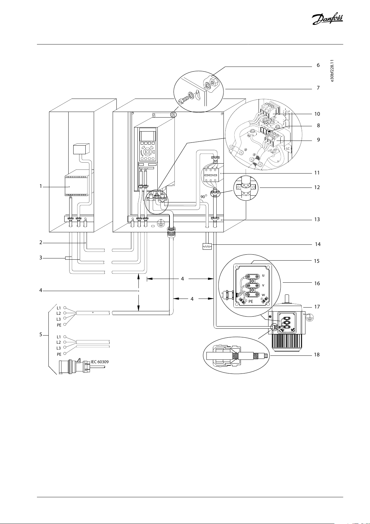
L1
L2L3PEL1L2L3PEPEu
v
w
2
1
3
5
IEC 60309
16
17
18
14
12
8
7
10
9
4
11
13
446
15
90
+DC
BR-
B
M
AINS
L1 L2 L3
91 92 93
RELA
Y 1 RELA
Y 2
99
- L
C -
UV
W
MO
T
OR
VLT® AQUA Drive FC 202
Operating Guide
Electrical Installation
Illustration 19: Example of Proper EMC Installation
AQ262141056213en-000201 / 130R0882 | 51Danfoss A/S © 2021.11

1
Programmable logic controller (PLC)
2
Minimum 16 mm2 (6 AWG) equalizing cable
3
Control cables
4
Minimum 200 mm (7.9 in) between control cables,
motor cables, and mains cables
5
Mains supply options, see IEC/EN 61800-5-1
6
Bare (unpainted) surface
7
Star washers
8
Brake cable (shielded) – not shown, but same
gounding principle applies as for motor cable
9
Motor cable (shielded)
10
Mains cable (unshielded)
11
Output contactor, and so on
12
Cable insulation stripped
13
Common ground busbar. Follow local and national
requirements for cabinet grounding
14
Brake resistor
15
Terminal box
16
Connection to motor
17
Motor
18
EMC cable gland
VLT® AQUA Drive FC 202
Operating Guide
Electrical Installation
N O T I C E
EMC INTERFERENCE
Use shielded cables for motor and control wiring, and separate cables for input power, motor wiring, and control wiring. Failure
to isolate power, motor, and control cables can result in unintended behavior or reduced performance. Minimum 200 mm (7.9 in)
clearance is required between power, motor, and control cables.
AQ262141056213en-000201 / 130R088252 | Danfoss A/S © 2021.11

1
2
(NC)
91 (L1)
92 (L2)
93 (L3)
18 (D IN)
15 mA
200 mA
(U) 96
(PE) 99
0/4-20 mA
03
0 V DC - 10 V DC
0/4–20 mA
02
01
05
04
06
24 V (NPN)
0 V (PNP)
0 V (PNP)
24 V (NPN)
19 (D IN)
24 V (NPN)
0 V (PNP)
24 V
0 V
0 V (PNP)
24 V (NPN)
0 V
24 V
24 V (NPN)
0 V (PNP)
0 V (PNP)
24 V (NPN)
33 (D IN)
32 (D IN)
1
2
ON
A53 U-I (S201)
ON
2
1
A54 U-I (S202)
ON=0–20 mA
OFF=0–10 V
95 (PE)
P 5-00
(R+) 82
(R-) 81
+ - + -
2)
0 V
5 V
S801
21
ON
Switch mode
power supply
ON=Terminated
OFF=Open
(NPN) = Sink
37 (D IN) - option
1)
e30bg569.10
Drive
Control compartment
XD2
Terminal
block
XD2.21
XD2.23
XD2.22
XD2.24
XD2.26
XD2.25
XD2.4
XD2.
5
XD2.2
XD2.3
XD2.1
XD2.19
XD2.17
XD2.16
XD2.15
XD2.14
XD2.18
XD2.13
XD2.12
XD2.11
XD2.10
XD2.9
XD2.8
XD2.7
XD2.6
cabinet
(V) 97
(W) 98
240 V AC, 2A
400 V AC, 2A
240 V AC, 2A
400 V AC, 2A
Brake temp
RS485
(PNP) = Source
(COM RS485) 61
(N RS485) 69
(P RS485) 68
RS485
Interface
OFF-ON
S801/Bus term.
(COM A OUT) 39
(A OUT) 42
10 V DC
24 V DC
3-phase
50 (+10 V OUT)
+10 V DC
power
input
0 V DC - 10 V DC
0/4–20 mA
29 (D IN/OUT)
27 (D IN/OUT)
20 (COM D IN)
13 (+24 V OUT)
12 (+24 V OUT)
55 (COM A IN)
54 (A IN)
53 (A IN)
Motor
Brake resistor
(option)
Relay1
Relay2
Analog output
1
Terminal 37 (optional) is used for Safe Torque Off. Refer to the VLT® FC Series - Safe Torque Off Operating Guide for
installation instructions.
VLT® AQUA Drive FC 202
Operating Guide
5.3 Wiring Overview for D9h and D10h Enclosed Drives
Electrical Installation
Illustration 20: Basic Wiring Overview for Enclosures D9h and D10h
AQ262141056213en-000201 / 130R0882 | 53Danfoss A/S © 2021.11
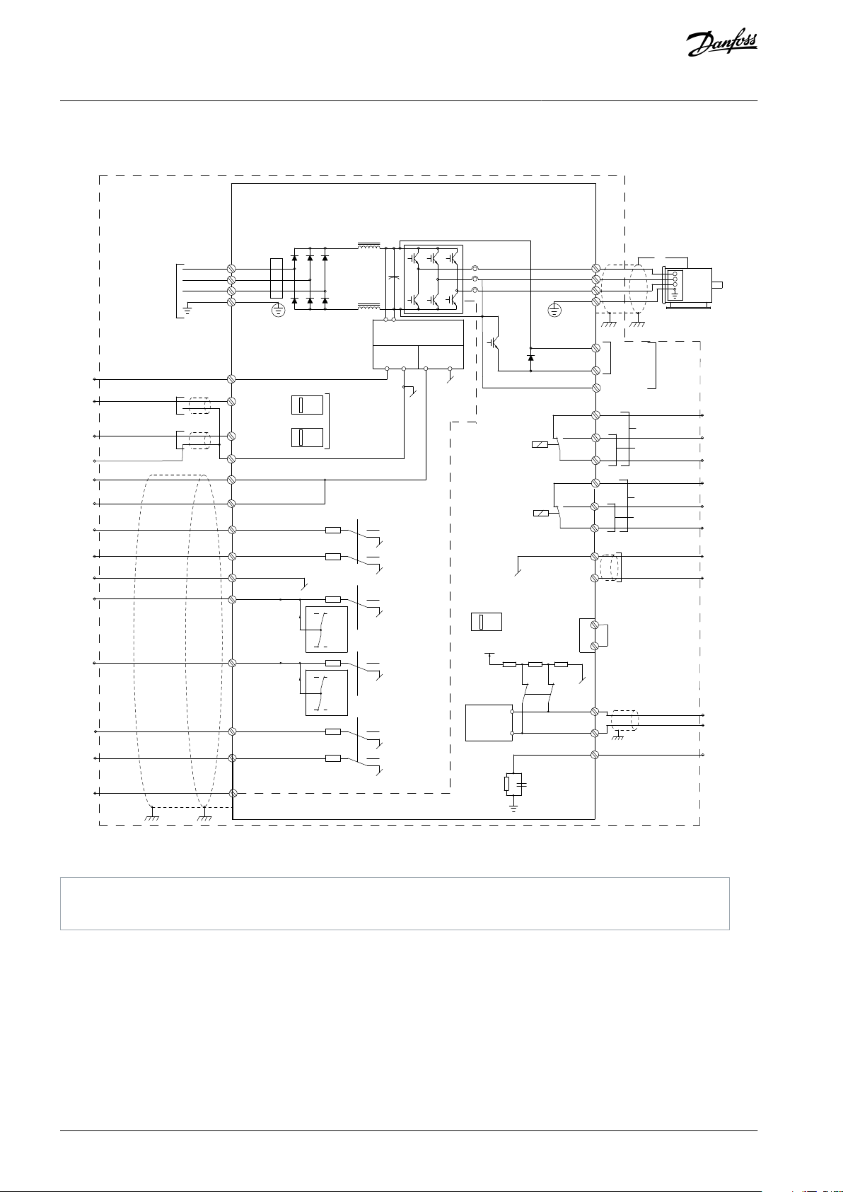
1
2
(NC)
91 (L1)
92 (L2)
93 (L3)
18 (D IN)
15 mA
200 mA
(U) 96
(PE) 99
0/4-20 mA
03
0 V DC - 10 V DC
0/4–20 mA
02
01
05
04
06
24 V (NPN)
0 V (PNP)
0 V (PNP)
24 V (NPN)
19 (D IN)
24 V (NPN)
0 V (PNP)
24 V
0 V
0 V (PNP)
24 V (NPN)
0 V
24 V
24 V (NPN)
0 V (PNP)
0 V (PNP)
24 V (NPN)
33 (D IN)
32 (D IN)
1
2
ON
A53 U-I (S201)
ON
2
1
A54 U-I (S202)
ON=0–20 mA
OFF=0–10 V
95 (PE)
P 5-00
(R+) 82
(R-) 81
+ - + -
2)
0 V
5 V
S801
21
ON
Switch mode
power supply
ON=Terminated
OFF=Open
(NPN) = Sink
=
=
=
37 (D IN) - option
1)
e30bu149.10
Drive
Control compartment
XD2
Terminal
block
XD2.21
XD2.23
XD2.22
XD2.24
XD2.26
XD2.25
XD2.4
XD2.
5
XD2.2
XD2.3
XD2.1
XD2.19
XD2.17
XD2.16
XD2.15
XD2.14
XD2.18
XD2.13
XD2.12
XD2.11
XD2.10
XD2.9
XD2.8
XD2.7
XD2.6
cabinet
(V) 97
(W) 98
240 V AC, 2A
400 V AC, 2A
240 V AC, 2A
400 V AC, 2A
Brake temp
RS485
(PNP) = Source
(COM RS485) 61
(N RS485) 69
(P RS485) 68
RS485
Interface
OFF-ON
S801/Bus term.
(COM A OUT) 39
(A OUT) 42
10 V DC
24 V DC
3-phase
50 (+10 V OUT)
+10 V DC
power
input
0 V DC - 10 V DC
0/4–20 mA
29 (D IN/OUT)
27 (D IN/OUT)
20 (COM D IN)
13 (+24 V OUT)
12 (+24 V OUT)
55 (COM A IN)
54 (A IN)
53 (A IN)
Motor
Brake
resistor
Relay1
Relay2
Analog output
(R-) 83
Regen+
Regen-
Regen
(option)
(option)
1
Terminal 37 (optional) is used for Safe Torque Off. Refer to the VLT® pFC Series - Safe Torque Off Operating Guide for
installation instructions.
VLT® AQUA Drive FC 202
Operating Guide
5.4 Wiring Overview for E5h and E6h Enclosed Drives
Electrical Installation
Illustration 21: Basic Wiring Overview for Enclosures E5h and E6h
AQ262141056213en-000201 / 130R088254 | Danfoss A/S © 2021.11

e30bu100.11
19
18
17
16
15
14
13
12
11
10
9
8
7
6
5
4
3
2
1
12 13 18 19 27 29 32 33 20 37
39696861 42 50 53 54 55
1
26
25
24
23
22
21
R 1 R 2
01 02 03 04 05
06
XD2
3
2
4
5
1
User-accessible terminals (control compartment)
2
Serial communication terminals (drive module)
3
Analog input/output terminals (drive module)
4
Digital input/output terminals (drive module)
5
Relay terminals (drive module)
VLT® AQUA Drive FC 202
Operating Guide
5.5 Control Terminal Wiring Diagram Cross-reference
Electrical Installation
Illustration 22: Serial Communication, Digital Input/Output, Analog Input/Output, and Relay Terminals Cross-reference
AQ262141056213en-000201 / 130R0882 | 55Danfoss A/S © 2021.11

VLT® AQUA Drive FC 202
Operating Guide
5.6 Split Shipment Wiring Harnesses
5.6.1 Connecting Wiring Harnesses
Procedure
1.
Follow the recommended cable routing between cabinets, if applicable. See the Cable Routing section.
2.
Connect the wiring harnesses according to how the enclosed drive is split. Each wiring harness in the enclosed drive is
labeled. Refer to the illustrations in the appropriate wiring harness sections.
a.
Connect the fan supply wiring harness.
b.
Connect the thermal protection harness.
c.
If applicable, connect the PHF contactor harnesses.
d.
If applicable, connect the cabinet heater harness.
3.
Connect the output filter cables. Refer to the illustrations in the appropriate wiring harness sections.
-
For the sine-wave filter option, there is 1 set of cables for each sine-wave filter. One end of each cable is already connected to the filter, the other end is bundled in the sine-wave filter cabinet. Connect the unattached sine-wave cable ends
to the motor terminals inside the drive cabinet.
-
For the dU/dt filter option, the unattached filter cables are bundled inside the dU/dt filter cabinet. Connect the unattached cable ends to the motor terminals within the drive cabinet.
4.
Connect the input filter cables. Refer to the illustrations in the appropriate wiring harness sections.
-
For the passive harmonic filter (PHF) option, the filter cables are bundled inside the input filter cabinet. First connect
the unattached PHF cable ends (R/S/T) to the corresponding terminals in the input power options cabinet. Then connect the unattached PHF cable ends (L1R/L2S/L3T) to the R/S/T terminals in the drive cabinet.
-
For the line reactor option, the line reactor cables are bundled inside the input filter cabinet. First connect the unattached line reactor cable ends (R/S/T) to the corresponding terminals in the input power options cabinet. Then connect the
unattached line reactor cable ends (L1R/L2S/L3T) to the R/S/T terminals in the drive cabinet.
Electrical Installation
AQ262141056213en-000201 / 130R088256 | Danfoss A/S © 2021.11
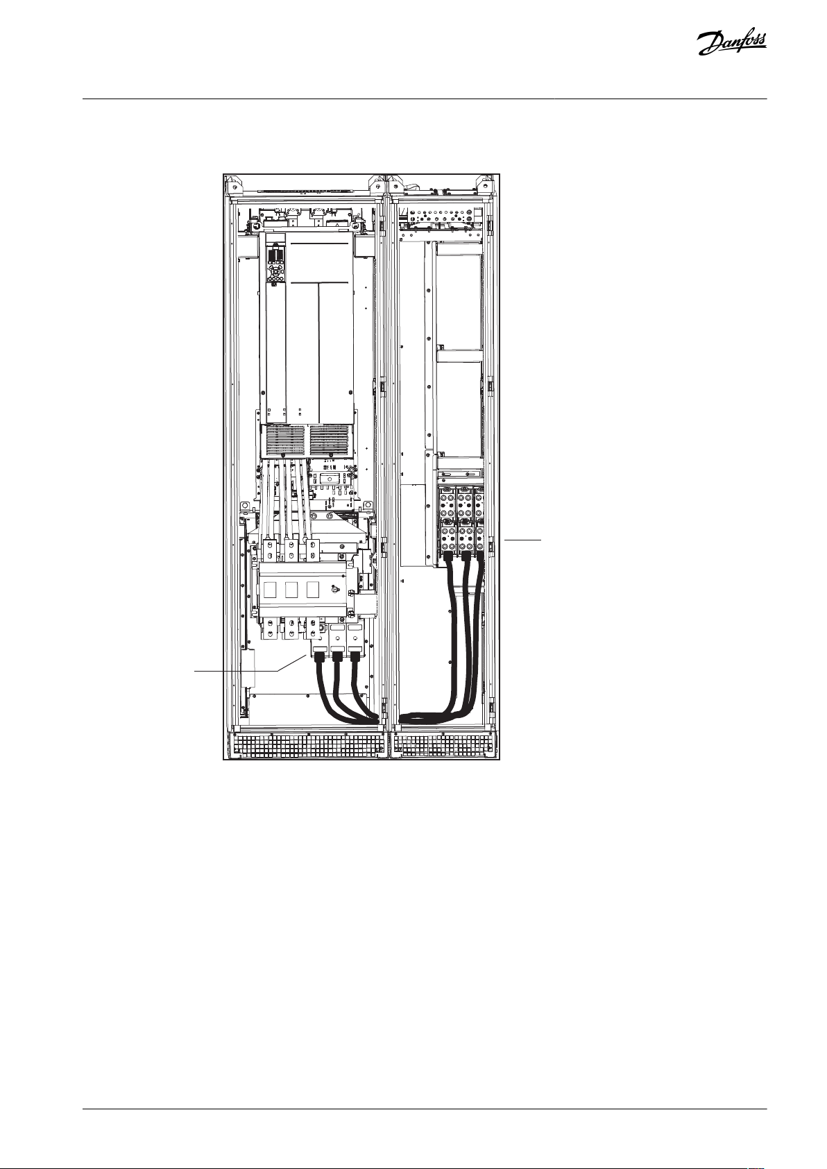
e30bu858.10
U, V, W
U/T1, V/T2, W/T3
VLT® AQUA Drive FC 202
Operating Guide
5.6.2 Cable Routing
Electrical Installation
Illustration 23: Cable Routing for Top Exit Cabinet to Drive Cabinet
AQ262141056213en-000201 / 130R0882 | 57Danfoss A/S © 2021.11

e30bu859.10
U/T1, V/T2, W/T3
VLT® AQUA Drive FC 202
Operating Guide
Electrical Installation
Illustration 24: Cable Routing for Sine-wave Cabinet to D10h Drive Cabinet
AQ262141056213en-000201 / 130R088258 | Danfoss A/S © 2021.11

e30bu874.10
U/T1, V/T2, W/T3
VLT® AQUA Drive FC 202
Operating Guide
Electrical Installation
Illustration 25: Cable Routing for Sine-wave Cabinet to E5h or E6h Drive Cabinet
AQ262141056213en-000201 / 130R0882 | 59Danfoss A/S © 2021.11

e30bu860.10
U, V, W
U/T1, V/T2, W/T3
VLT® AQUA Drive FC 202
Operating Guide
Electrical Installation
Illustration 26: Cable Routing for dU/dt Cabinet with Top Exit to E5h or E6h Drive Cabinet
AQ262141056213en-000201 / 130R088260 | Danfoss A/S © 2021.11

e30bu861.10
U/T1, V/T2, W/T3
VLT® AQUA Drive FC 202
Operating Guide
Electrical Installation
Illustration 27: Cable Routing for 2 Sine-wave Cabinets to E5h or E6h Drive Cabinet
AQ262141056213en-000201 / 130R0882 | 61Danfoss A/S © 2021.11

e30bu862.10
R/L1, S/L2, T/L3
R, S, T
R/L1, S/L2, T/L3
R, S, T
VLT® AQUA Drive FC 202
Operating Guide
Electrical Installation
Illustration 28: Cable Routing for PHF Cabinet to E5h or E6h Drive Cabinet
AQ262141056213en-000201 / 130R088262 | Danfoss A/S © 2021.11

e30bu863.10
U/T1, V/T2, W/T3
VLT® AQUA Drive FC 202
Operating Guide
Electrical Installation
Illustration 29: Cable Routing for dU/dt Cabinet to Top Exit Cabinet for E5h or E6h
AQ262141056213en-000201 / 130R0882 | 63Danfoss A/S © 2021.11

L1R, L2S, L3T
R, S, T
L1R, L2S, L3T
R, S, T
e30bu873.10
VLT® AQUA Drive FC 202
Operating Guide
Electrical Installation
Illustration 30: Cable Routing for Line Reactor Cabinet to Input Power Options Cabinet and E6h Drive Cabinet (Internal Wiring Connection Be-
tween Inductors in the Line Reactor Cabinet Is Not Shown)
AQ262141056213en-000201 / 130R088264 | Danfoss A/S © 2021.11
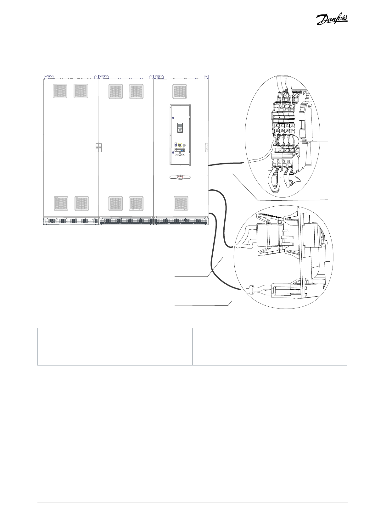
-XDL.1
-XD4.1
-XD11.1
1
2
3
4
e30bu179.11
1
DC-link harness to fan supply in output filter cabinet
2
Cabinet heater supply harness to output filter cabinet3Additional terminal connections
4
Thermal protection wiring harness to output filter
cabinet
VLT® AQUA Drive FC 202
Operating Guide
5.6.3 D10h Wiring Harness
Electrical Installation
Illustration 31: Split Shipment Electrical Connections (Input Filter Cabinet + Input Power Options Cabinet + D10h Drive Cabinet)
AQ262141056213en-000201 / 130R0882 | 65Danfoss A/S © 2021.11

e30bu181.12
-XD4.1
-XD11.1
-XDL.1
1
2
3
4
U W
V
5
1
Additional terminal connections
2
Thermal protection wiring harness to drive cabinet
3
DC-link harness to fan supply in drive cabinet
4
Cabinet heater supply harness to drive cabinet
5
Motor cables (U/V/W) to motor terminals (U/V/W) in
drive cabinet
VLT® AQUA Drive FC 202
Operating Guide
Electrical Installation
Illustration 32: Split Shipment Electrical Connections (dU/dt Cabinet + Top Exit Cabinet)
AQ262141056213en-000201 / 130R088266 | Danfoss A/S © 2021.11

e30bu182.10
U
W
V
1
1
Motor cables (U/V/W) to motor terminals (U/V/W) in drive cabinet
VLT® AQUA Drive FC 202
Operating Guide
Electrical Installation
Illustration 33: Split Shipment Electrical Connections (Top Exit Cabinet)
AQ262141056213en-000201 / 130R0882 | 67Danfoss A/S © 2021.11
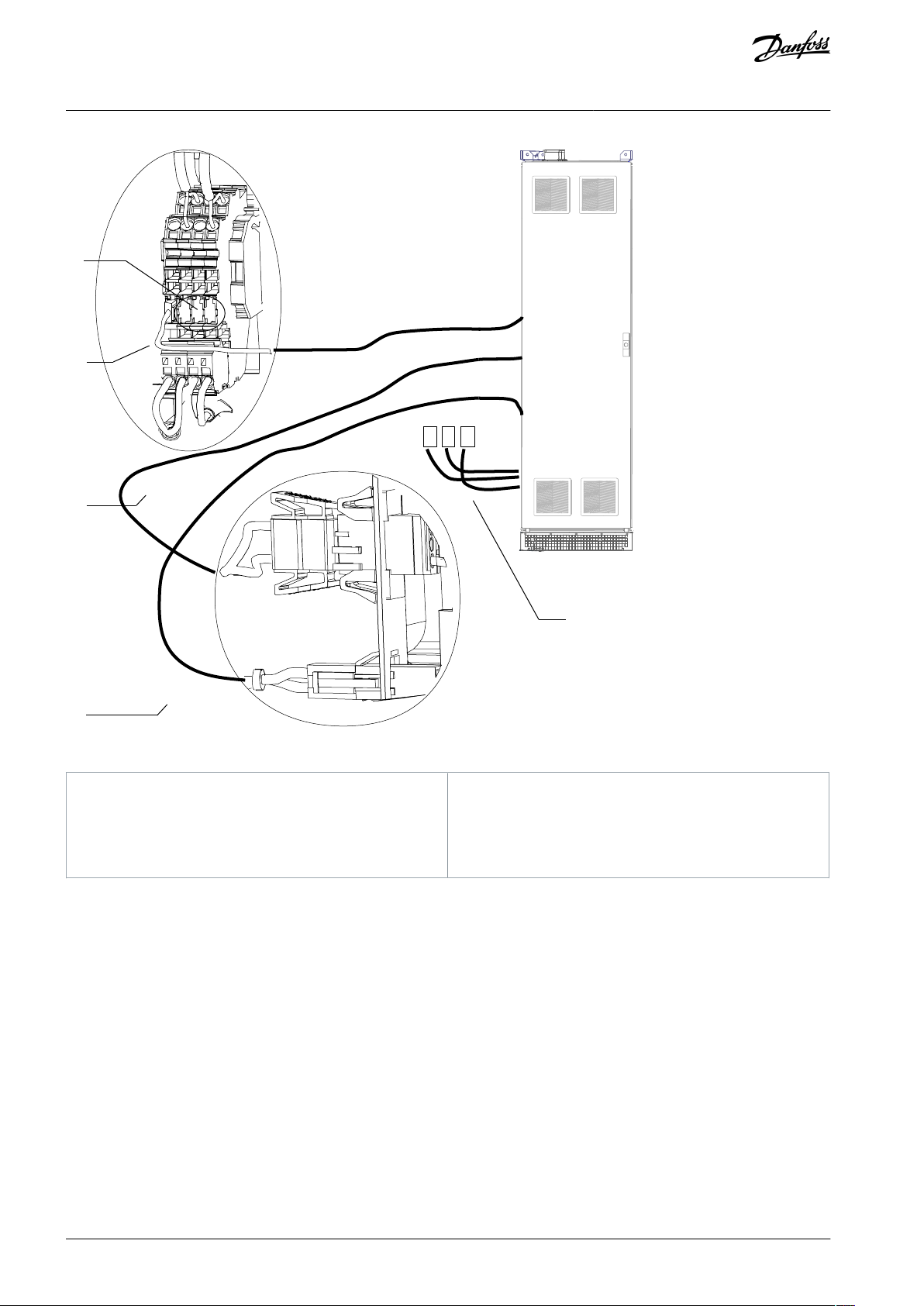
e30bu183.12
U
W
V
-XD4.1
-XD11.1
-XDL.1
1
2
4
3
5
1
Additional terminal connections
2
Thermal protection wiring harness to drive cabinet
3
DC-link harness to fan supply in drive cabinet
4
Cabinet heater supply harness to drive cabinet
5
Motor cables (U/V/W) to motor terminals (U/V/W) in
drive cabinet
VLT® AQUA Drive FC 202
Operating Guide
Electrical Installation
Illustration 34: Split Shipment Electrical Connections (D10h Sine-wave Cabinet)
AQ262141056213en-000201 / 130R088268 | Danfoss A/S © 2021.11
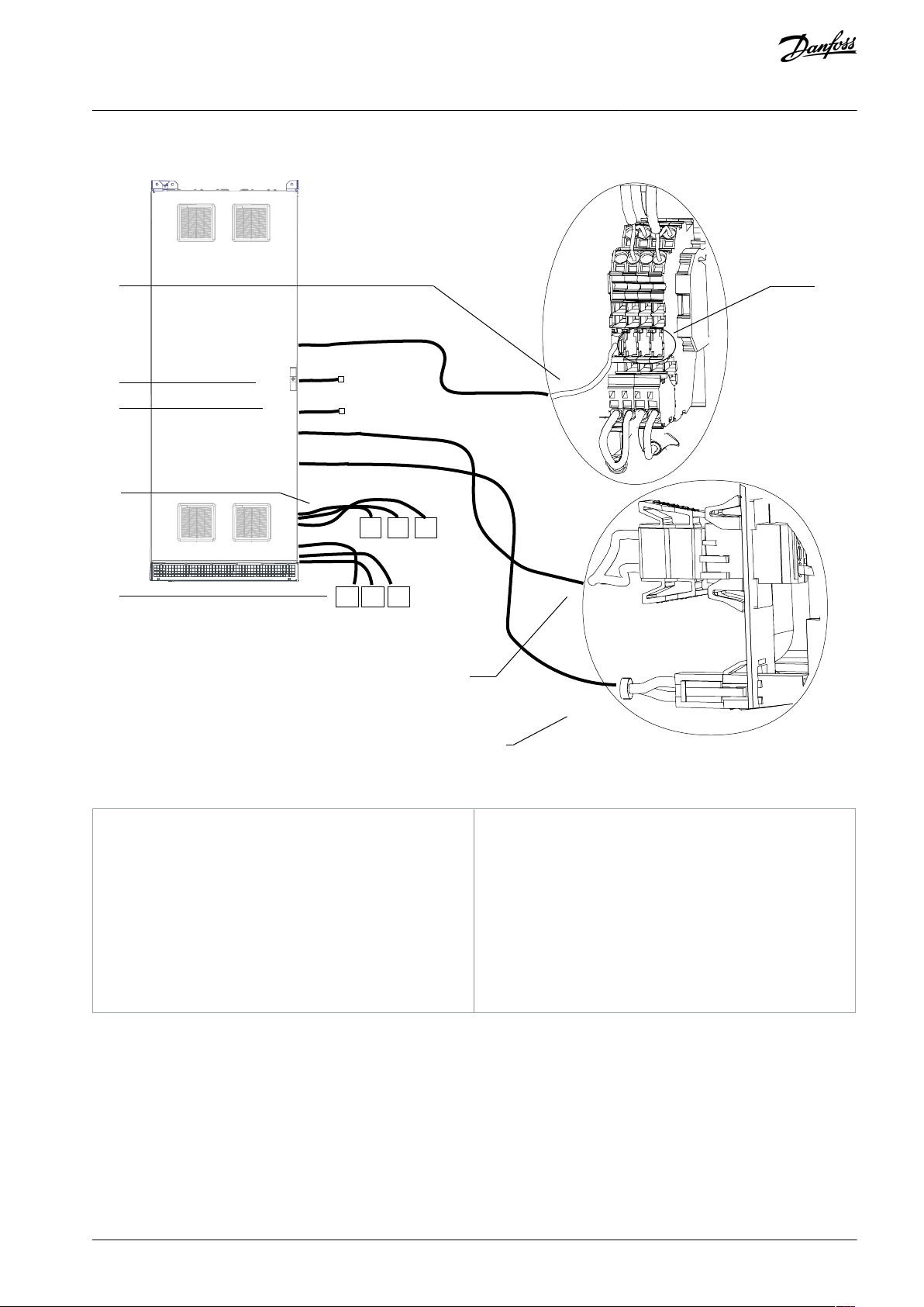
e30bu180.10
-XDL.1
-XD4.1
-XD11.3
-XD4.4
-XD4.3
1
2
3
4
5
8
L1R
T
R
S
L3T
L2S
6
7
1
Thermal protection wiring harness to input power
options cabinet
2
PHF contactor 1 supply harness to input power options cabinet (only with PHF option)
3
PHF contactor 2 supply harness to input power options cabinet (only with PHF option)
4
Input terminal cables (R/S/T) to mains terminals
(R/S/T) in the input power options cabinet
5
Output terminal cables (L1R/L2S/L3T) to mains terminals (R/S/T) in the drives cabinet
6
DC-link harness to fan supply in the input power options cabinet
7
Cabinet heater supply harness to input power options cabinet
8
Additional terminal connections
VLT® AQUA Drive FC 202
Operating Guide
5.6.4 E5h Wiring Harness
Electrical Installation
Illustration 35: Split Shipment Electrical Connections (Input Filter Cabinet)
AQ262141056213en-000201 / 130R0882 | 69Danfoss A/S © 2021.11

e30bu181.12
-XD4.1
-XD11.1
-XDL.1
1
2
3
4
U W
V
5
1
Additional terminal connections
2
Thermal protection wiring harness to drive cabinet
3
DC-link harness to fan supply in drive cabinet
4
Cabinet heater supply harness to drive cabinet
5
Motor cables (U/V/W) to motor terminals (U/V/W) in
drive cabinet
VLT® AQUA Drive FC 202
Operating Guide
Electrical Installation
Illustration 36: Split Shipment Electrical Connections (dU/dt Cabinet + Top Exit Cabinet)
AQ262141056213en-000201 / 130R088270 | Danfoss A/S © 2021.11
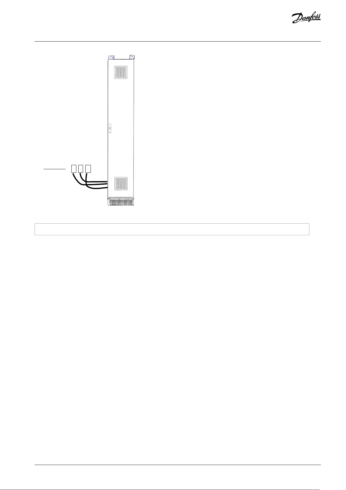
e30bu182.10
U
W
V
1
1
Motor cables (U/V/W) to motor terminals (U/V/W) in drive cabinet
VLT® AQUA Drive FC 202
Operating Guide
Electrical Installation
Illustration 37: Split Shipment Electrical Connections (Top Exit Cabinet)
AQ262141056213en-000201 / 130R0882 | 71Danfoss A/S © 2021.11

e30bu188.12
U
W
-XD4.1
-XD11.1
-XDL.1
3
4
U
W
1
2
5
1
Additional terminal connections
2
Thermal protection wiring harness to drive cabinet
3
DC-link harness to fan supply in drive cabinet
4
Cabinet heater supply harness to drive cabinet
5
Motor cables (U/V/W) to motor terminals (U/V/W) in
drive cabinet
VLT® AQUA Drive FC 202
Operating Guide
Electrical Installation
Illustration 38: Split Shipment Electrical Connections (E5h/E6h Sine-wave Cabinets)
AQ262141056213en-000201 / 130R088272 | Danfoss A/S © 2021.11
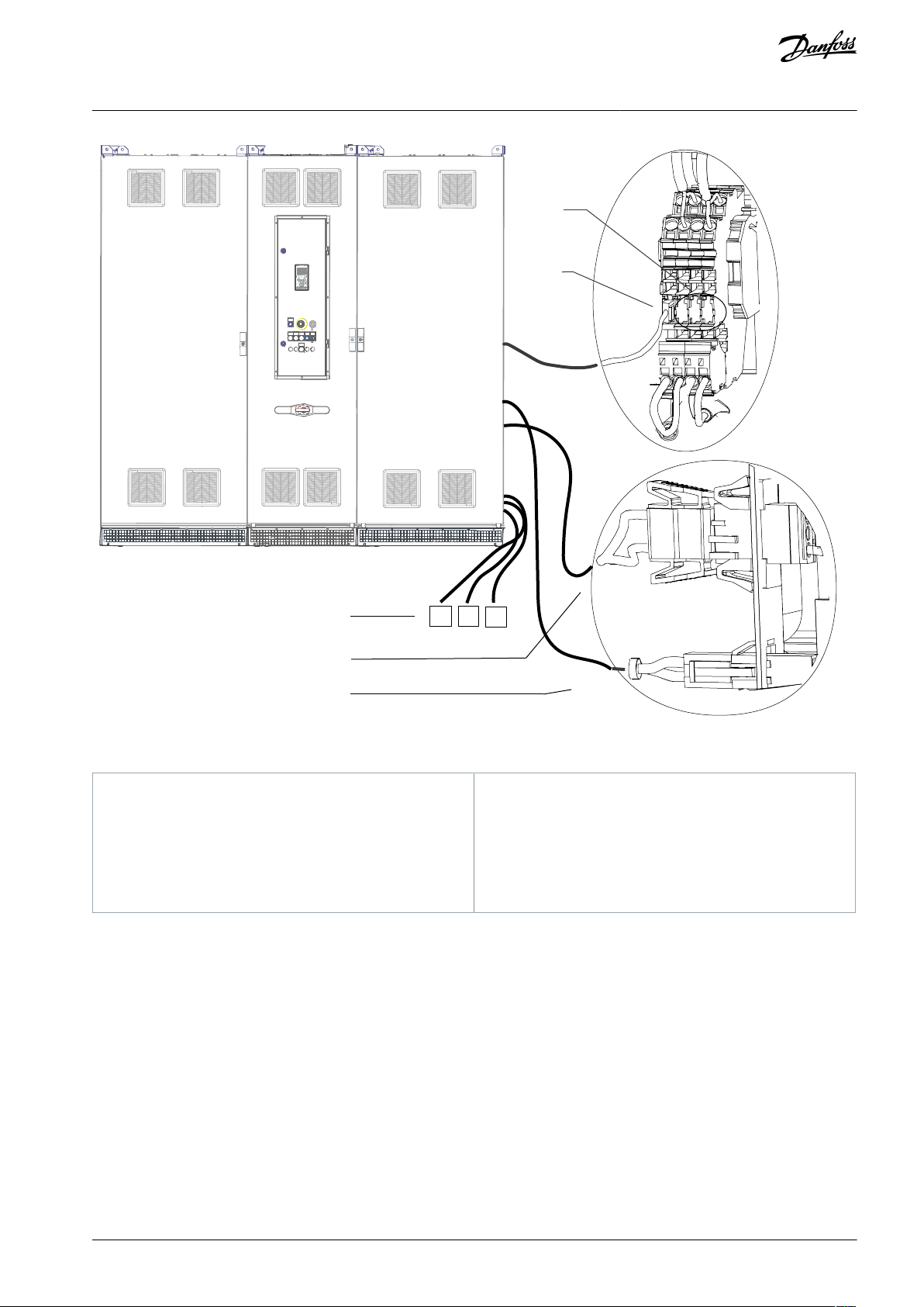
e30bu186.11
-XDL.1
-XD4.1
-XD11.1
1
2
5
W
U
V
4
3
1
Motor cables (U/V/W) to motor terminals (U/V/W) in
output filter cabinet
2
DC-link harness to fan supply in output filter cabinet
3
Cabinet heater supply harness to output filter cabinet4Additional terminal connections
5
Thermal protection wiring harness to output filter
cabinet
VLT® AQUA Drive FC 202
Operating Guide
Electrical Installation
Illustration 39: Split Shipment Electrical Connections (Input Filter Cabinet + Input Power Options Cabinet + E5h Drive Cabinet)
AQ262141056213en-000201 / 130R0882 | 73Danfoss A/S © 2021.11

e30bu187.11
-XDL.1
-XD4.1
-XD11.1
7
8
9
10
R
TS
-XD4.1
-XD4.3
-XD11.3
-XDL.1
2
3
4
5
6
L1R
L3T
L2S
1
1
Cabinet heater supply harness to input filter cabinet
2
DC-link harness to fan supply in input filter cabinet
3
Thermal protection harness to input filter cabinet
4
PHF contactor 1 supply harness to input filter cabinet (only with PHF option)
5
Mains cables (R/S/T) to input terminals (R/S/T) in the
input filter cabinet
6
Mains cables (L1R/L2S/L3T) to output terminals
(L1R/L2S/L3T) in the input filter cabinet
7
DC-link harness to fan supply to output filter cabinet
8
Cabinet heater supply harness to output filter cabinet9Available terminal connections
10
Thermal protection wiring harness to output filter
cabinet
VLT® AQUA Drive FC 202
Operating Guide
Electrical Installation
Illustration 40: Split Shipment Electrical Connections (Input Power Options Cabinet + E5h Drive Cabinet)
AQ262141056213en-000201 / 130R088274 | Danfoss A/S © 2021.11

e30bu180.10
-XDL.1
-XD4.1
-XD11.3
-XD4.4
-XD4.3
1
2
3
4
5
8
L1R
T
R
S
L3T
L2S
6
7
1
Thermal protection wiring harness to input power
options cabinet
2
PHF contactor 1 supply harness to input power options cabinet (only with PHF option)
3
PHF contactor 2 supply harness to input power options cabinet (only with PHF option)
4
Input terminal cables (R/S/T) to mains terminals
(R/S/T) in the input power options cabinet
5
Output terminal cables (L1R/L2S/L3T) to mains terminals (R/S/T) in the drives cabinet
6
DC-link harness to fan supply in the input power options cabinet
7
Cabinet heater supply harness to input power options cabinet
8
Additional terminal connections
VLT® AQUA Drive FC 202
Operating Guide
5.6.5 E6h Wiring Harness
Electrical Installation
Illustration 41: Split Shipment Electrical Connections (Input Filter Cabinet)
AQ262141056213en-000201 / 130R0882 | 75Danfoss A/S © 2021.11

e30bu181.12
-XD4.1
-XD11.1
-XDL.1
1
2
3
4
U W
V
5
1
Additional terminal connections
2
Thermal protection wiring harness to drive cabinet
3
DC-link harness to fan supply in drive cabinet
4
Cabinet heater supply harness to drive cabinet
5
Motor cables (U/V/W) to motor terminals (U/V/W) in
drive cabinet
VLT® AQUA Drive FC 202
Operating Guide
Electrical Installation
Illustration 42: Split Shipment Electrical Connections (dU/dt Cabinet + Top Exit Cabinet)
AQ262141056213en-000201 / 130R088276 | Danfoss A/S © 2021.11

e30bu182.10
U
W
V
1
1
Motor cables (U/V/W) to motor terminals (U/V/W) in drive cabinet
VLT® AQUA Drive FC 202
Operating Guide
Electrical Installation
Illustration 43: Split Shipment Electrical Connections (Top Exit Cabinet)
AQ262141056213en-000201 / 130R0882 | 77Danfoss A/S © 2021.11

e30bu188.12
U
W
-XD4.1
-XD11.1
-XDL.1
3
4
U
W
1
2
5
1
Additional terminal connections
2
Thermal protection wiring harness to drive cabinet
3
DC-link harness to fan power supply in drive cabinet
4
Cabinet heater supply harness to drive cabinet
5
Motor cables (U/V/W) to motor terminals (U/V/W) in
drive cabinet
VLT® AQUA Drive FC 202
Operating Guide
Electrical Installation
Illustration 44: Split Shipment Electrical Connections (E5h/E6h Sine-wave Cabinets)
AQ262141056213en-000201 / 130R088278 | Danfoss A/S © 2021.11

e30bu185.11
-XD4.1
7
8
3
5
6
-XD4.4
4
-XD11.3
-XDL.1
1
2
R
TS
L1R
L3T
L2S
-XD4.3
1
Additional terminal connections
2
Thermal protection wiring harness to input filter
cabinet
3
DC-link harness to fan supply in the input filter cabinet4Cabinet heater supply harness to input filter cabinet
5
PHF contactor 1 supply harness to input filter cabinet (only with PHF option)
6
PHF contactor 2 supply harness to input filter cabinet (only with PHF option)
7
Mains cables (R/S/T) to input terminals (R/S/T) in the
input filter cabinet
8
Mains cables (L1R/L2S/L3T) to output terminals
(L1R/L2S/L3T) in the input filter cabinet
VLT® AQUA Drive FC 202
Operating Guide
Electrical Installation
Illustration 45: Split Shipment Electrical Connections (Input Power Options Cabinet + E6h Drive Cabinet + Top Exit Cabinet)
AQ262141056213en-000201 / 130R0882 | 79Danfoss A/S © 2021.11
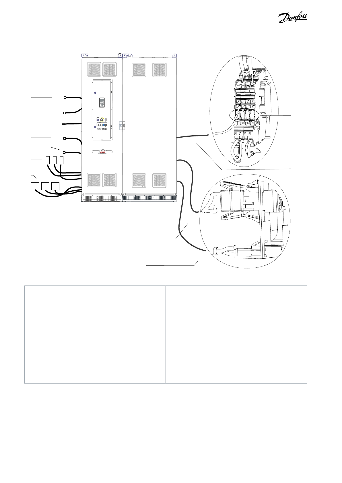
e30bu184.11
-XDL.1
-XD4.1
-XD11.1
8
9
10
11
R
TS
-XD4.3
-XD11.3
-XDL.1
2
3
4
6
7
-XD4.4
5
L1R
L3T
L2S
-XD4.1
1
1
Cabinet heater supply harness to input filter cabinet
2
DC-link harness to fan supply to input filter cabinet
3
Thermal protection wiring harness in the input filter
cabinet
4
PHF contactor 1 supply harness to PHF cabinet (only
with PHF option)
5
PHF contactor 2 supply harness to PHF cabinet (only
with PHF option)
6
Mains cables R, S, T to input terminals (R/S/T) in the
input filter cabinet
7
Mains cables (L1R/L2S/L3T) to output terminals
(L1R/L2S/L3T) in the input filter cabinet
8
DC-link harness to fan supply in output filter cabinet
9
Cabinet heater supply harness to output filter cabinet10Available terminal connections
11
Thermal protection wiring harness to output filter
cabinet
VLT® AQUA Drive FC 202
Operating Guide
Electrical Installation
Illustration 46: Split Shipment Electrical Connections (Input Power Options Cabinet + E6h Drive Cabinet)
AQ262141056213en-000201 / 130R088280 | Danfoss A/S © 2021.11

e30bu148.10
R S T
R S T U V W
L1R L2S
L3T
R S T
VLT® AQUA Drive FC 202
Operating Guide
Electrical Installation
Illustration 47: Connecting Motor and Mains Cables (Example Shows a PHF Cabinet + Input Power Options Cabinet + E6h Drive Cabinet + Sine-
wave Cabinets)
5.7 Control Compartment Wiring
5.7.1 Safety Precautions
W A R N I N G
HIGH VOLTAGE
The mains disconnect switch does not disconnect the external voltage supply. Failure to disconnect the external voltage supply
before touching any components in the control compartment can result in death or serious injury.
Only qualified personnel must install, start up, and maintain the drive.
-
Disconnect the external voltage supply.
-
AQ262141056213en-000201 / 130R0882 | 81Danfoss A/S © 2021.11
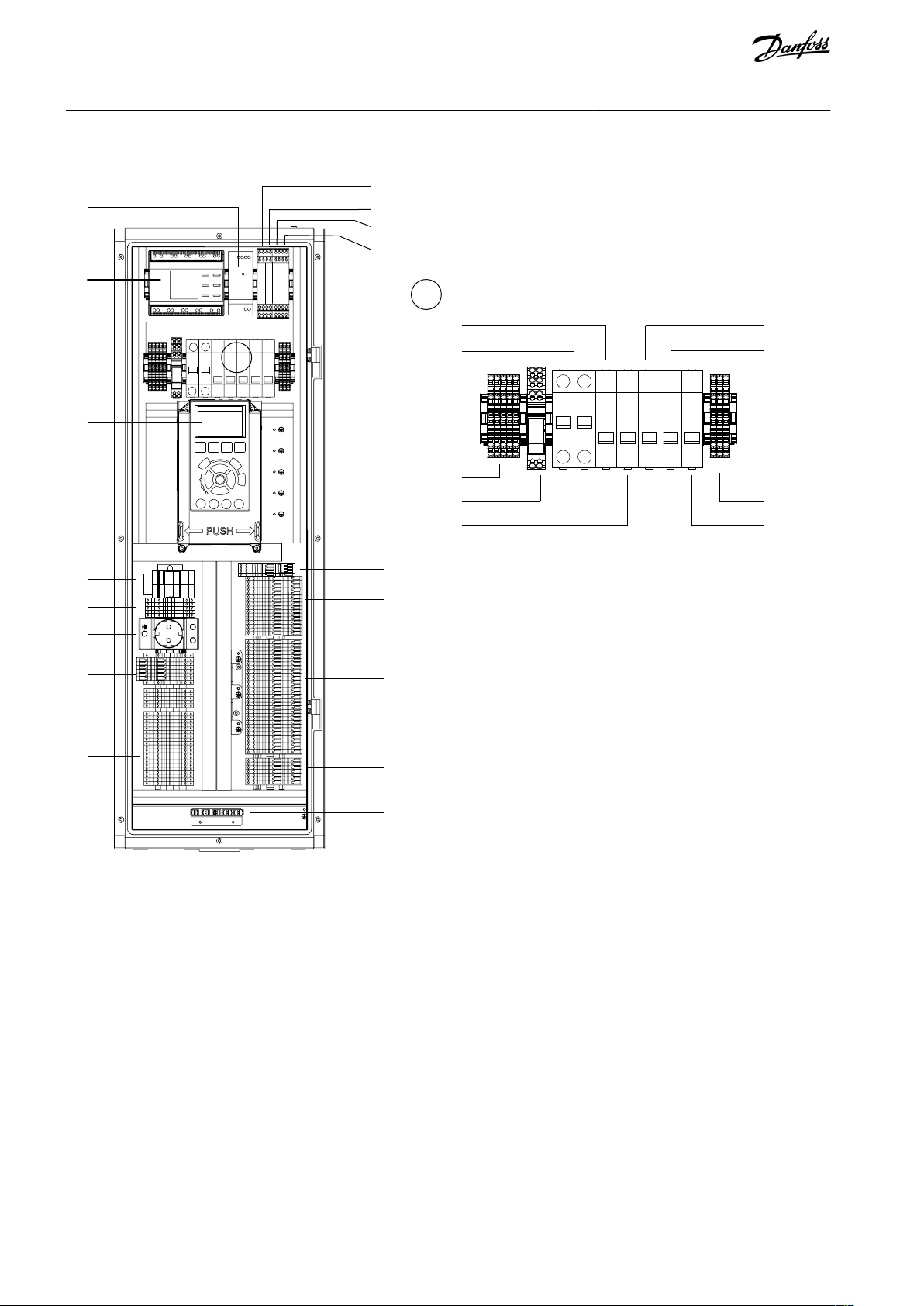
e30bu140.10
2
17
15
16
18
14
20
19
21
22
3
A
6
7
8
9
24
25
26
1
10
11
A
12
13
4
5
23
27
VLT® AQUA Drive FC 202
Operating Guide
5.7.2 Control Compartment Interior View
Electrical Installation
Illustration 48: Layout of Control Compartment Interior with All Options
AQ262141056213en-000201 / 130R088282 | Danfoss A/S © 2021.11
1
24 V DC supply (-TB7)
2
Insulation monitor (-BE1)
3
Local control panel (LCP)
4
RJ45 terminal blocks 1 and 2 (-RJ45_1 and RJ45_2)
5
Protection terminal block set (-XD11)
6
Socket outlet (-XD10)
7
Contactor control circuit terminal block (-XD0)
8
Cabinet heater terminal block (-XD4)
9
Customer terminal block/option C0 terminal block (XDW)
10
Thermal trip indicator relay, input power options
cabinet (-KFJ.1)
11
Thermal trip indicator relay, output filter cabinet (KFJ.2)
12
Thermal trip indicator relay, input filter cabinet (KFJ.3)
13
PHF capacitor connect/disconnect contactor relay (QAF)14+24 DC supply protection MCB (-FC7)
15
AC circuit protection MCB (-FC6)
16
AC distribution circuit terminal block (-XD1)
17
Auxiliary relay for heater (-QAM)
18
Contactor control circuit protection MCB (-FC10)
19
Cabinet light/socket outlet protection MCB (-FCC)
20
Cabinet heater(s) circuit protection MCB (-FCE)
21
DC distribution circuit terminal block (-XD3)
22
Motor heater circuit protection MCB (-FCN)
23
AC fan supply terminal block set (-XDY)
24
Option C2 terminal block set (-XDF)
25
Basic I/O terminal block and option A, B, D card terminal block set (-XD2)
26
Door components terminal block set (-XDJ)
27
Grounding clamp for the shield termination of wires
XD2 terminal
Parameter
Default
Setting
Description
1––
Integrated RC-filter for cable shield. Used only for connecting the shield in
case of EMC problems.
2
Parameter group 8-3* FC
Port Settings
–
RS485 interface. A switch (BUS TER.) is provided on the control card for bus
termination resistance. See Illustration 5.22.
3
Parameter group 8-3* FC
Port Settings
–
XD2 terminal
Parameter
Default setting
Description
10, 11
–
+24 V DC
24 V DC supply voltage for digital inputs and external transducers. Maximum output current 200 mA for all 24 V loads.
12
Parameter 5-10 Terminal 18 Digital
Input
[8] Start
Digital inputs.
13
Parameter 5-11 Terminal 19 Digital
Input
[10] Reversing
16
Parameter 5-14 Terminal 32 Digital
Input
[0] No operation
VLT® AQUA Drive FC 202
Operating Guide
Electrical Installation
5.7.3 Control Terminals
Table 43: Serial Communication Terminals
Table 44: Digital Input/Output Terminal Descriptions
AQ262141056213en-000201 / 130R0882 | 83Danfoss A/S © 2021.11
XD2 terminal
Parameter
Default setting
Description
17
Parameter 5-15 Terminal 33 Digital
Input
[0] No operation
14
Parameter 5-12 Terminal 27 Digital
Input
[2] Coast inverse
For digital input or output. Default setting is input.
15
Parameter 5-13 Terminal 29 Digital
Input
[14] JOG
18––
Common for digital inputs and 0 V potential for 24 V supply.
19–STO
When not using the optional STO feature, a jumper wire is required between terminal XD2.10 (or XD2.11) and terminal
XD2.19. This set-up allows the drive to operate with factory
default programming values.
XD2 terminal
Parameter
Default setting
Description
4––
Common for analog output.
5
Parameter 6-50 Terminal 42 Output
[0] No operation
Programmable analog output. 0–20 mA or 4–20 mA at a maximum of 500 Ω.
6–+10 V DC
10 V DC analog supply voltage for potentiometer or thermistor. 15 mA maximum.
7
Parameter group 6-1* Analog Input 1
Reference
Analog input. For voltage (V) or current (mA).
8
Parameter group 6-2* Analog Input 2
Feedback
9––
Common for analog input.
XD2 terminal
Parameter
Default setting
Description
21, 22, 23
Parameter 5-40 Function Relay [0]
[0] No operation
Form C relay outputs. For AC or DC voltage.
24, 25, 26
Parameter 5-40 Function Relay [1]
[0] No operation
VLT® AQUA Drive FC 202
Operating Guide
Table 45: Analog Input/Output Terminal Descriptions
Electrical Installation
5.7.4 Relay Terminals
Table 46: Relay Terminal Descriptions
5.7.5 Option Card Terminals
The option cards extend the functionality of drives and provide a high variety of interfaces to automation systems. When the option
cards are specified in the type code, they are mounted in slots A, B, C, and D of the control card within the drive module. The option
card wiring is routed to a terminal block within the control compartment. For more details, refer to the Installation/Operating Guide
for the respective option card.
OPTION CARD INSTALLATION
If the option card is ordered along with the drive using the type code, the factory installs the option card and its wiring. If the
option is ordered separately, the customer is responsible for installing the option card and the wiring extensions to the control
compartment.
N O T I C E
AQ262141056213en-000201 / 130R088284 | Danfoss A/S © 2021.11

Option card terminal
Corresponding terminal within the control compartment
1
XD2.40
2
XD2.41
3
XD2.42
4
XD2.43
5
XD2.44
Option card terminal
Corresponding terminal within the control compartment
67
XD2.40
66
XD2.41
63
XD2.42
62
XD2.43
CS
XD2.44
Option card terminal
Corresponding terminal within the control compartment
Port 1
RJ45_1
Port 2
RJ45_2
Option card terminal
Corresponding terminal within the control compartment
1
XD2.46
2
XD2.47
3
XD2.48
4
XD2.49
5
XD2.50
6
XD2.51
7
XD2.52
8
XD2.53
9
XD2.54
10
XD2.55
11
XD2.56
12
XD2.57
VLT® AQUA Drive FC 202
Operating Guide
Table 47: Option A Terminal Connections for VLT® DeviceNet MCA 104, VLT® CANopen MCA 105, VLT® DeviceNet Converter MCA 194
Table 48: Option A Terminal Connections for VLT® PROFIBUS DP-V1 MCA 101, VLT® PROFIBUS Converter VLT 300 MCA 113, VLT® PROFIBUS
Converter VLT 5000 MCA 114
Electrical Installation
Table 49: Option A Terminal Connections for VLT® EtherNet/IP MCA 121, VLT® Modbus TCP MCA 122, VLT® POWERLINK MCA 123, VLT® Ether-
CAT MCA 124
Table 50: Option B Terminal Connections
AQ262141056213en-000201 / 130R0882 | 85Danfoss A/S © 2021.11

Option card terminal
Corresponding terminal within the control compartment
X45.1
XDF.17
X45.2
XDF.18
X45.3
XDF.19
X45.4
XDF.20
X46.1
XDF.1
X46.2
XDF.2
X46.3
XDF.3
X46.4
XDF.4
X46.5
XDF.5
X46.6
XDF.6
X46.7
XDF.7
X46.8
XDF.8
X46.9
XDF.9
X46.10
XDF.10
X46.11
XDF.11
X46.12
XDF.12
X46.13
XDF.13
X46.14
XDF.14
X47.1
XDF.21
X47.2
XDF.22
X47.3
XDF.23
X47.4
XDF.24
X47.5
XDF.25
X47.6
XDF.26
X47.7
XDF.27
X47.8
XDF.28
X47.9
XDF.29
X47.10
XDF.30
X47.11
XDF.31
X47.12
XDF.32
X58.1
XDF.15
X58.2
XDF.16
VLT® AQUA Drive FC 202
Operating Guide
Table 51: Option C1 Terminal Connections for VLT® Extended Relay Card MCB 113
Electrical Installation
AQ262141056213en-000201 / 130R088286 | Danfoss A/S © 2021.11

Option card terminal
Corresponding terminal within the control compartment
X67.1
XDF.21
X67.2
XDF.22
X67.3
XDF.23
X67.4
XDF.24
X67.5
XDF.25
X67.6
XDF.26
X67.7
XDF.27
X67.8
XDF.28
X67.9
XDF.29
X67.10
XDF.30
X67.11
XDF.31
X67.12
XDF.32
X66.1
XDF.1
X66.2
XDF.2
X66.3
XDF.3
X66.4
XDF.4
X66.5
XDF.5
X66.6
XDF.6
X66.7
XDF.7
X66.8
XDF.8
X66.9
XDF.9
X66.10
XDF.10
X66.11
XDF.11
X66.12
XDF.12
X66.13
XDF.13
X66.14
XDF.14
X58.1
XDF.15
X58.2
XDF.16
VLT® AQUA Drive FC 202
Operating Guide
Table 52: Option C1 Terminal Connections for VLT® Advanced Cascade Controller MCO 102
Electrical Installation
AQ262141056213en-000201 / 130R0882 | 87Danfoss A/S © 2021.11
Option card terminal
Corresponding terminal within the control compartment
35
XD2.28
36
XD2.29
Character position
Code
Description
21
1
230 V AC external
5
230 V AC external + 24 V DC internal
6
120 V AC external
9
120 V AC external + 24 V DC internal
e30bu195.10
-XD1.1
-FC6
-XD1
10 A
2
Character position
Code
Description
21
2
230 V AC internal
4
230 V AC internal + 24 V DC internal
7
120 V AC internal
8
120 V AC internal + 24 V DC internal
VLT® AQUA Drive FC 202
Operating Guide
Table 53: Option D Terminal Connections
5.7.6 Control Compartment Options
5.7.6.1 Auxiliary Supply Terminals
Table 54: Auxiliary Supply Type Codes
Electrical Installation
The auxiliary supply terminal option provides an external voltage supply to the –XD1.1 terminal. The external supply must be shortcircuit protected. The power of the external supply depends on other selected cabinet options.
Illustration 49: Auxiliary AC Supply Terminals
W A R N I N G
HIGH VOLTAGE
The mains disconnect switch does not disconnect the external voltage supply. Failure to disconnect the external voltage supply
before touching any components in the control compartment can result in death or serious injury.
Disconnect the external voltage supply.
-
Only qualified personnel must install, start up, and maintain the drive.
-
5.7.6.2 Auxiliary Voltage Transformer
Table 55: Auxiliary Supply Type Codes for Auxiliary Voltage Transformer
The auxiliary voltage transformer is an option fitted internally that allows for the supply to be tapped from the mains. For example,
if the enclosed drive is specified with a fused disconnect, the supply for the auxiliary voltage transformer is taken from between the
drive and the fused disconnect. This configuration allows the control voltage to be disconnected with the main switch.
The transformer has multiple tappings on the primary side for the standard range of voltages on which the drive operates. The
factory default wiring connects to the highest voltage tapping on the primary side, and the trip settings for the -FC4 terminal is set
AQ262141056213en-000201 / 130R088288 | Danfoss A/S © 2021.11

e30bu192.10
L1-L2
-FC4
-TA4
2
3
#
-FC6
-XD1
4 A
1
2
Character position
Code
Description
21
4
230 V AC internal+24 V DC internal
5
230 V AC external+24 V DC internal
8
120 V AC internal+24 V DC internal
9
120 V AC external+24 V DC internal
e30bu194.10
L1-L2
-FC7
-TB7
1
24 V
-XD1
2 A
N
L
+
~
+
60 W
Character position
Code
Description
23–24
A1
AC socket + cabinet light
AA
AC socket + cabinet light + extended I/O terminals
AB
AC socket + cabinet light + cabinet heater
VLT® AQUA Drive FC 202
Operating Guide
Electrical Installation
accordingly. The customer can change the tapping provided the correct voltage is applied and the thermal magnetic circuit breaker
is set accordingly.
Illustration 50: Auxiliary Voltage Transformer Terminals
N O T I C E
AUXILIARY COMPONENT FAILURE
Incorrect voltage or incorrect tapping installation will cause other auxiliary components in the control compartment to fail.
When tapping the transformer, make sure to apply the correct voltage for the drive.
-
Use the correct tapping and trip settings.
-
5.7.6.3 +24 V DC External Supply
Table 56: Auxiliary Supply Type Codes
The 24 V DC external supply option enables other auxiliary options to be connected to a 24 V DC supply within the control compartment.
Illustration 51: 24 V DC External Supply Terminals
5.7.6.4 AC Customer Socket
Table 57: Auxiliary Function Type Codes
AQ262141056213en-000201 / 130R0882 | 89Danfoss A/S © 2021.11

Character position
Code
Description
AC
AC socket + cabinet light + motor heater control
AD
AC socket + cabinet light + insulation monitor
AE
AC socket + cabinet light + extended I/O terminals + cabinet heater
AF
AC socket + cabinet light + extended I/O terminals + motor heater control
AG
AC socket + cabinet light + extended I/O terminals + insulation monitor
AH
AC socket + cabinet light + extended I/O terminals + cabinet heater + motor heater control
AI
AC socket + cabinet light + extended I/O terminals + cabinet heater + insulation monitor
AJ
AC socket + cabinet light + extended I/O terminals + motor heater control + insulation monitor
AK
AC socket + cabinet light + extended I/O terminals + cabinet heater + motor heater control + insulation monitor
AL
AC socket + cabinet light + cabinet heater + motor heater control
AM
AC socket + cabinet light + cabinet heater + insulation monitor
AN
AC socket + cabinet light + cabinet heater + motor heater control + insulation monitor
AO
AC socket + cabinet light + motor heater control + insulation monitor
e30bu193.10
-XD1
-FCC
-XD10
1
-XD1
2 A
N
L
Character position
Code
Description
23–24
A2
Extended I/O terminals
AA
AC socket+cabinet light + extended I/O terminals
AE
AC socket+cabinet light + extended I/O terminals + cabinet heater
AF
AC socket+cabinet light + extended I/O terminals + motor heater control
AG
AC socket+cabinet light + extended I/O terminals + insulation monitor
AH
AC socket+cabinet light + extended I/O terminals + cabinet heater + motor heater control
AI
AC socket+cabinet light + extended I/O terminals + cabinet heater + insulation monitor
VLT® AQUA Drive FC 202
Operating Guide
Electrical Installation
The customer socket provides a supply for measurement tools, equipment, or a computer. The socket type is CEE 7/3 ("Schuko",
Type F) or NEMA 5-15 grounded (Type B). The default voltage is 230 V AC (IEC variant) and 115 V AC (UL variant). When using an
external supply, the maximum output power is 450 VA (IEC variant) and 230 VA (UL variant). When using a transformer supply, the
maximum output power is 200 VA for both variants.
Illustration 52: AC Customer Socket Terminals
5.7.6.5 Extended I/O Terminals
Table 58: Auxiliary Function Type Codes
AQ262141056213en-000201 / 130R088290 | Danfoss A/S © 2021.11

Character position
Code
Description
AJ
AC socket+cabinet light + extended I/O terminals + motor heater control + insulation monitor
AK
AC socket+cabinet light + extended I/O terminals + cabinet heater + motor heater control + insulation
monitor
AP
Extended I/O terminals + cabinet heater
AQ
Extended I/O terminals + motor heater control
AR
Extended I/O terminals + insulation monitor
AS
Extended I/O terminals + cabinet heater + motor heater control
AT
Extended I/O terminals + cabinet heater + insulation monitor
AU
Extended I/O terminals + cabinet heater + motor heater control + insulation monitor
AV
Extended I/O terminals + motor heater control + insulation monitor
Character position
Code
Description
23–24
A3
Cabinet heater
AB
AC socket + cabinet light + cabinet heater
AE
AC socket + cabinet light + extended I/O terminals + cabinet heater
AH
AC socket + cabinet light + extended I/O terminals + cabinet heater + motor heater control
AI
AC socket + cabinet light + extended I/O terminals + cabinet heater + insulation monitor
AK
AC socket + cabinet light + extended I/O terminals + cabinet heater + motor heater control + insulation monitor
AL
AC socket + cabinet light + cabinet heater + motor heater control
AM
AC socket + cabinet light + cabinet heater + insulation monitor
AN
AC socket + cabinet light + cabinet heater + motor heater control + insulation monitor
AP
Extended I/O terminals + cabinet heater
AS
Extended I/O terminals + cabinet heater + motor heater control
AT
Extended I/O terminals + cabinet heater + insulation monitor
AU
Extended I/O terminals + cabinet heater + motor heater control + insulation monitor
AW
Cabinet heater + motor heater control
A8
Cabinet heater + insulation monitor
AY
Cabinet heater + motor heater control + insulation monitor
VLT® AQUA Drive FC 202
Operating Guide
The extended I/O terminal option includes 25 control terminals (-XDW) in the control compartment for use by the customer. If the
enclosed drive is configured with any option C1 card, the -XDW terminal block is used for the option C1 card wiring.
Electrical Installation
5.7.6.6 Cabinet Heater
Table 59: Auxiliary Function Type Codes
AQ262141056213en-000201 / 130R0882 | 91Danfoss A/S © 2021.11

e30bu189.10
-XD1
-FCE
-QAM
1
-XD4
6 A
N
L
-EB1.4
-EB1.3
-EB1.2
-EB1.1
-XD4
Character position
Code
Description
23–24
A4
Motor heater control
AC
AC socket + cabinet light + motor heater control
AF
AC socket + cabinet light + extended I/O terminals + motor heater control
AH
AC socket + cabinet light + extended I/O terminals + cabinet heater + motor heater control
AJ
AC socket + cabinet light + extended I/O terminals + motor heater control + insulation monitor
AK
AC socket + cabinet light + extended I/O terminals + cabinet heater + motor heater control + insulation monitor
AL
AC socket + cabinet light + cabinet heater + motor heater control
AN
AC socket + cabinet light + cabinet heater + motor heater control + insulation monitor
AO
AC socket + cabinet light + motor heater control + insulation monitor
AQ
Extended I/O terminals + motor heater control
AS
Extended I/O terminals + cabinet heater + motor heater control
AU
Extended I/O terminals + cabinet heater + motor heater control + insulation monitor
AV
Extended I/O terminals + motor heater control + insulation monitor
AW
Cabinet heater + motor heater control
AY
Cabinet heater + motor heater control + insulation monitor
AZ
Motor heater control + insulation monitor
VLT® AQUA Drive FC 202
Operating Guide
Electrical Installation
The cabinet heater option increases the inside temperature of the cabinet above the ambient temperature, preventing condensation in the cabinet. Each cabinet has 1 cabinet heater. The heater element is self regulating. The external supply is connected to
terminal -XD1.1. When the drive is not in run state, the control relay -QAM changes the supply to the output terminals (-XD4). When
the drive is in run state, the control relay disconnects the supply to the cabinet heater. The function is disabled when MCB –FCE is
open.
Illustration 53: Cabinet Heater Terminals
5.7.6.7 Motor Heater Control
Table 60: Auxiliary Function Type Codes
AQ262141056213en-000201 / 130R088292 | Danfoss A/S © 2021.11

e30bu191.10
-
XD1
-FCE
-
QAM
1
-XD4
6 A
N
L
-XDM
A
Character position
Code
Description
23–24
A5
Insulation monitor
AD
AC socket+cabinet light + insulation monitor
AG
AC socket+cabinet light + extended I/O terminals + insulation monitor
AI
AC socket+cabinet light + extended I/O terminals + cabinet heater + insulation monitor
AJ
AC socket+cabinet light + extended I/O terminals + motor heater control + insulation monitor
AK
AC socket+cabinet light + extended I/O terminals + cabinet heater + motor heater control + insulation monitor
AM
AC socket+cabinet light + cabinet heater + insulation monitor
AN
AC socket+cabinet light + cabinet heater + motor heater control + insulation monitor
AO
AC socket+cabinet light + motor heater control + insulation monitor
AR
Extended I/O terminals + insulation monitor
AT
Extended I/O terminals + cabinet heater + insulation monitor
AU
Extended I/O terminals + cabinet heater + motor heater control + insulation monitor
AV
Extended I/O terminals + motor heater control + insulation monitor
A8
Cabinet heater + insulation monitor
AY
Cabinet heater + motor heater control + insulation monitor
AZ
Motor heater control + insulation monitor
VLT® AQUA Drive FC 202
Operating Guide
Electrical Installation
The motor heater option provides the ability to control the supply for the motor anti-condensation heater. The 24 V DC external
supply is connected to terminal -XD1.1 in the lower part of the cabinet. When the drive is not in run state, the control relay -QAM
changes the external supply to the -XDM output terminals. When the drive is in run state, the control relay disconnects the external
supply to the motor heater. The function is disabled when MCB –FCN is open.
Illustration 54: Motor Heater Control (A = Heater element, not included)
5.7.6.8 Insulation Monitor
Table 61: Auxiliary Function Type Codes
The insulation monitor option monitors the supply and insulation faults within the insulation level in an IT supply network with an
insulation monitor in the control compartment.
AQ262141056213en-000201 / 130R0882 | 93Danfoss A/S © 2021.11

Character position
Code
Description
28–29
D1
Signal lights and reset button
DA
Signal lights and reset button + emergency switch off and emergency push-button
DB
Signal lights and reset button + STO with emergency push-button (no functional safety)
DC
Signal lights and reset button + STO/SS1 with emergency push-button + safely limited speed (TTL
encoder)
DE
Signal lights and reset button + STO/SS1 with emergency push-button + safely limited speed (HTL
encoder)
Character position
Code
Description
28–29
D2
Emergency switch off + emergency push-button
DA
Signal lights and reset button + emergency switch off and emergency push-button
Character position
Code
Description
28–29
D3
STO with emergency push-button (no functional safety)
DB
Signal lights and reset button + STO with emergency push-button (no functional safety)
Character position
Code
Description
28–29
D4
STO/SS1 with emergency push-button+safely limited speed (TTL encoder)
DC
Indicator lights and reset button + STO/SS1 with emergency push-button+safely limited speed
(TTL encoder)
VLT® AQUA Drive FC 202
Operating Guide
Electrical Installation
5.7.6.9 Signal Lights and Reset Buttons
Table 62: Door-mounted Option Type Codes
The signal light and reset button option includes signal lights on the control compartment door for run and fault states of the AC
drive. The door also has a button for the reset function of the drive.
5.7.6.10 Emergency Switch Off
Table 63: Door-mounted Option Type Codes
The emergency switch off option uses an input contactor to disconnect the drive from mains. Pushing the emergency stop pushbutton on the control compartment door opens the control circuit of the input contactor.
5.7.6.11 STO with Emergency Push-button on Door
Table 64: Door-mounted Option Type Codes
This option provides the STO (Safe Torque Off) function via an emergency push-button mounted on the door of the control compartment. The control terminals of the control card are extended from inside the drive module and routed out to the terminal block
set -XD2 in the control compartment. The emergency push-button is wired between terminals -XD2.10 and -XD2.19.
Activating the emergency push-button prevents the unit from generating the voltage required to rotate the motor. The option provides:
•
Safe Torque Off (STO), as defined by EN IEC 61800-5-2.
•
Stop Category 0, as defined in EN 60204-1.
5.7.6.12 STO/SS1 with Emergency Push-button + Safely Limited Speed (TTL Encoder) on Door
Table 65: Door-mounted Option Type Codes
AQ262141056213en-000201 / 130R088294 | Danfoss A/S © 2021.11

Character position
Code
Description
28–29
D5
STO/SS1 with emergency push-button + safely limited speed (HTL encoder)
DE
Signal lights and reset button + STO/SS1 with emergency push-button + safely limited speed (HTL
encoder)
VLT® AQUA Drive FC 202
Operating Guide
This option provides the SS1 (Safe Stop 1) function with the VLT® Safety Option MCB 150 along with STO function using an emergency stop push-button on the control compartment door. The emergency stop push-button activates the motor deceleration and
makes the motor stop in the set deceleration ramp time. Basic wiring for the S37 terminal of the option card to terminal 37 of control card and the emergency push-button wiring are provided
MCB 150 is used when the standstill or the motor speed is measured using a TTL encoder. For detailed instructions, refer to the VLT
Safety Option MCB 150/151 Installation Guide. MCB 150 can be programmed using the VLT® Motion Control Tool MCT 10 software
to take advantage of the following functional safety features:
Safe Torque Off (STO).
•
No power is being fed to the motor which can generate a rotation. Stop category 0 to EN IEC 60204-1.
Safe Stop 1 (SS1).
•
The motor decelerates. Monitoring of deceleration ramp and STO following zero speed, or STO at the end of a deceleration
time. Stop category 1 to EN IEC 60204-1.
Safely limited speed (SLS).
•
This function prevents exceeding a defined speed value. See the OPT-B option board and safety relay user manuals for the regu-
lations and the certified safety.
Electrical Installation
5.7.6.13 STO/SS1 with Emergency Push-button + Safely Limited Speed (HTL Encoder) on Door
Table 66: Door-mounted Option Type Codes
®
This option provides the SS1 (Safe Stop 1) function with the VLT® Safety Option MCB 151 along with STO function using an emergency stop push-button on the control compartment door. The option is compatible with HTL encoders or PNP proximity switches.
The emergency stop-push button activates the motor deceleration and makes the motor stop in the set deceleration ramp time.
Basic wiring for the S37 terminal of the option card to terminal 37 of control card and the emergency push-button wiring are provided
MCB 151 is used when the standstill or the motor speed is measured using a TTL encoder. For detailed instructions, refer to the VLT
Safety Option MCB 150/151 Installation, Guide. MCB 151 can be programmed using VLT® Motion Control Tool MCT 10 software to
take advantage of the following functional safety features:
Safe Torque Off (STO).
•
No power is being fed to the motor which can generate a rotation. Stop category 0 to EN IEC 60204-1.
Safe Stop 1 (SS1).
•
The motor decelerates. Monitoring of deceleration ramp and STO following zero speed, or STO at the end of a deceleration
time. Stop category 1 to EN IEC 60204-1.
Safely limited speed (SLS).
•
This function prevents exceeding a defined speed value. See the OPT-B option board and safety relay user manuals for the regu-
lations and the certified safety.
5.8 Connecting Motor, Mains, and Ground Cables
5.8.1 Power Cabling and Grounding Considerations
Motor and mains connections
•
Size the wiring according to the input current of the drive. For maximum wire sizes, see the Electrical Data section.
Use cables rated for 75 °C (167 °F) of insulation for UL installations.
•
Comply with local and national electrical codes for cable sizes.
•
Follow motor manufacturer wiring requirements.
•
Motor wiring knockouts or access panels are provided on the pedestal of IP21/IP54 (NEMA 1/NEMA 12) units.
•
Do not wire a starting or pole-changing device (for example Dahlander motor or slip ring induction motor) between the drive
•
and the motor.
®
AQ262141056213en-000201 / 130R0882 | 95Danfoss A/S © 2021.11
e30bu151.10
7
8
9
10
3
4
5
6
1 2
1
Cable 1
2
Cable 2
3
Connection bushing
4
Cable 1
5
Cable 2
6
Cable 3
7
Cable 1 lug
8
Bolt holder on the connector
9
Terminal connector
10
Cable 2 lug
VLT® AQUA Drive FC 202
Operating Guide
Ground connection
•
Ground the drive in accordance with applicable standards and directives.
•
Use a dedicated ground wire for input power, motor power, and control wiring.
•
Do not ground 1 drive to another in a daisy chain fashion.
•
Keep the ground wire connections as short as possible.
•
Follow motor manufacturer wiring requirements.
•
Minimum cable cross-section: 10 mm2 (6 AWG) (or 2 rated ground wires terminated separately).
•
Tighten the terminals in accordance with the information provided in 10.11 Fastener Torque Ratings.
EMC-compliant Installation
Refer to the EMC-compliant Installation section.
Electrical Installation
Illustration 55: Different Ways of Connecting Multiple Cables to 1 Terminal
5.8.2 Connecting to the Mains
If the enclosed drive is not configured with an input filter or input power option, connect the mains to the drive module. Otherwise,
connect the mains to the input power option.
Procedure
AQ262141056213en-000201 / 130R088296 | Danfoss A/S © 2021.11
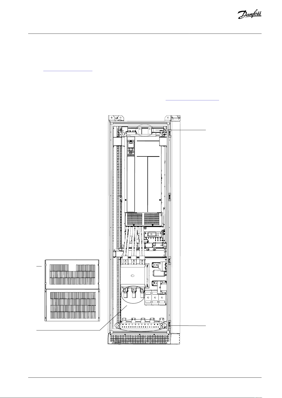
e30bu172.10
1
2
4
3
VLT® AQUA Drive FC 202
Operating Guide
1.
Strip a section of the outer cable insulation.
2.
Fasten a connector/cable lug to the end of the stripped cable.
3.
Create an electrical connection between the cable shield and ground by securing the stripped wire under the cable clamp.
4.
Connect the ground wire to the nearest grounding terminal in accordance with the grounding instructions provided in
5.8.6 Connecting to Ground.
5.
Connect the 3-phase AC input power cables to terminals R (L1), S (L2), and T (L3).
6.
When supplied from an isolated mains source (IT mains or floating delta) or TT/TN-S mains with a grounded leg (grounded
delta), ensure that parameter 14-50 RFI Filter is set to [0] Off to avoid damage to the DC link and to reduce ground capacity
currents.
7.
Tighten the terminals in accordance with the specifications shown in 10.11 Fastener Torque Ratings.
Example
Electrical Installation
Illustration 56: Connection Points for Mains to Input Power Option (Enclosed Drive Configured Without Power Options Cabinet)
AQ262141056213en-000201 / 130R0882 | 97Danfoss A/S © 2021.11
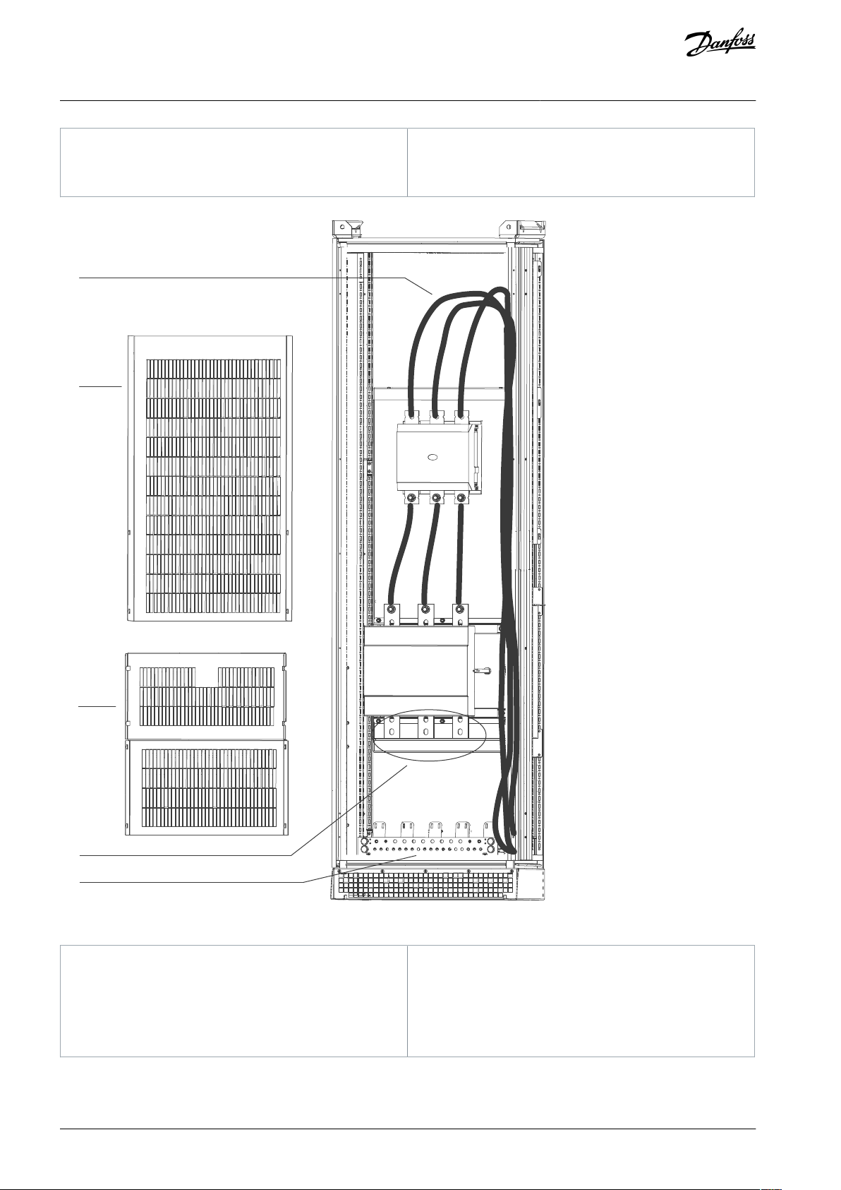
1
Lower cover
2
Input power terminals (contactor option is shown)
3
DC terminals
4
Grounding bar
e30bu173.10
1
2
3
4
5
1
Factory cables connecting contactor to drive input
terminals
2
Upper cover
3
Lower cover
4
Input power terminals (disconnect option is shown)
5
Grounding bar
VLT® AQUA Drive FC 202
Operating Guide
Electrical Installation
Illustration 57: Connection Points for Mains to Input Power Option (Enclosed Drive Configured With Power Options Cabinet)
5.8.3 Connecting the Drive Module to the Motor
Procedure
AQ262141056213en-000201 / 130R088298 | Danfoss A/S © 2021.11
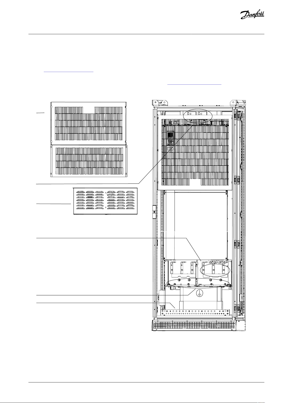
e30bu171.10
1
3
4
5
6
2
VLT® AQUA Drive FC 202
Operating Guide
1.
Strip a section of the outer cable insulation.
2.
Fasten a connector/cable lug to the end of the stripped cable.
3.
Create an electrical connection between the cable shield and ground by securing the stripped wire under the cable clamp.
4.
Connect the ground wire to the nearest grounding terminal in accordance with the grounding instructions provided in
5.8.6 Connecting to Ground.
5.
Connect the 3-phase AC motor cables to terminals U (T1), V (T2), and W (T3).
6.
Tighten the terminals in accordance with the specifications shown in 10.11 Fastener Torque Ratings.
Example
Electrical Installation
Illustration 58: Connection Points for Drive Module to Motor (E6h Model Shown)
AQ262141056213en-000201 / 130R0882 | 99Danfoss A/S © 2021.11

1
Lower cover
2
DC terminals
3
Terminal cover
4
Motor terminals
5
Ground terminals on drive module
6
Grounding bar
VLT® AQUA Drive FC 202
Operating Guide
5.8.4 Connecting the Sine-wave Filter to the Motor
Procedure
1.
Strip a section of the outer cable insulation.
2.
Fasten a connector/cable lug to the end of the stripped cable.
3.
Create an electrical connection between the cable shield and ground by securing the stripped wire under the cable clamp.
4.
Connect the ground cable to the nearest grounding terminal in accordance with the grounding instructions provided in
5.8.6 Connecting to Ground.
5.
Connect the 3-phase AC motor cable to the sine-wave terminals U, V, and W.
-
If the enclosed drive has 1 sine-wave filter cabinet, run 1 set of motor cables to the cabinet.
-
If the enclosed drive has 2 sine-wave filter cabinets, run 2 sets of motor cables, 1 set to each sine-wave filter cabinet.
N O T I C E
Each sine-wave cabinet must have the same number of motor phase cables and they must be in quantities of 2
-
(for example, 2, 4, 6, or 8). 1 cable is not allowed. The cables are required to be equal length.
Electrical Installation
AQ262141056213en-000201 / 130R0882100 | Danfoss A/S © 2021.11
 Loading...