

Danfoss FC 202 Operating guide
ENGINEERING TOMORROW
Operating Guide
VLT® AQUA Drive FC 202
0.25–90 kW
vlt-drives.danfoss.com


Contents |
Operating Guide |
|
|
Contents
1 Introduction |
4 |
1.1 Purpose of the Operating Guide |
4 |
1.2 Additional Resources |
4 |
1.3 Manual and Software Version |
4 |
1.4 Product Overview |
4 |
1.5 Approvals and Certi€cations |
8 |
1.6 Disposal |
8 |
2 Safety |
9 |
2.1 Safety Symbols |
9 |
2.2 Quali€ed Personnel |
9 |
2.3 Safety Precautions |
9 |
3 Mechanical Installation |
11 |
3.1 Unpacking |
11 |
3.2 Installation Environments |
11 |
3.3 Mounting |
12 |
4 Electrical Installation |
14 |
4.1 Safety Instructions |
14 |
4.2 EMC-compliant Installation |
14 |
4.3 Grounding |
14 |
4.4 Wiring Schematic |
16 |
4.5 Access |
18 |
4.6 Motor Connection |
18 |
4.7 AC Mains Connection |
19 |
4.8 Control Wiring |
19 |
4.8.1 Control Terminal Types |
19 |
4.8.2 Wiring to Control Terminals |
21 |
4.8.3 Enabling Motor Operation (Terminal 27) |
21 |
4.8.4 Voltage/Current Input Selection (Switches) |
22 |
4.8.5 RS485 Serial Communication |
22 |
4.9 Installation Check List |
23 |
5 Commissioning |
24 |
5.1 Safety Instructions |
24 |
5.2 Applying Power |
24 |
5.3 Local Control Panel Operation |
24 |
5.3.1 Graphic Local Control Panel Layout |
24 |
5.3.2 Parameter Settings |
26 |
MG20MD02 |
Danfoss A/S © 10/2016 All rights reserved. |
1 |

Contents |
VLT® AQUA Drive FC 202 |
5.3.3 Uploading/Downloading Data to/from the LCP |
26 |
5.3.4 Changing Parameter Settings |
26 |
5.3.5 Restoring Default Settings |
26 |
5.4 Basic Programming |
27 |
5.4.1 Commissioning with SmartStart |
27 |
5.4.2 Commissioning via [Main Menu] |
27 |
5.4.3 Asynchronous Motor Set-up |
28 |
5.4.4 PM Motor Setup in VVC+ |
28 |
5.4.5 SynRM Motor Set-up with VVC+ |
29 |
5.4.6 Automatic Energy Optimization (AEO) |
30 |
5.4.7 Automatic Motor Adaptation (AMA) |
30 |
5.5 Checking Motor Rotation |
31 |
5.6 Local-control Test |
31 |
5.7 System Start-up |
31 |
6 Application Set-up Examples |
32 |
7 Maintenance, Diagnostics, and Troubleshooting |
36 |
7.1 Maintenance and Service |
36 |
7.2 Status Messages |
36 |
7.3 Warning and Alarm Types |
38 |
7.4 List of Warnings and Alarms |
39 |
7.5 Troubleshooting |
46 |
8 Speci•cations |
49 |
8.1 Electrical Data |
49 |
8.1.1 Mains Supply 1x200–240 V AC |
49 |
8.1.2 Mains Supply 3x200–240 V AC |
50 |
8.1.3 Mains Supply 1x380–480 V AC |
52 |
8.1.4 Mains Supply 3x380–480 V AC |
53 |
8.1.5 Mains Supply 3x525–600 V AC |
57 |
8.1.6 Mains Supply 3x525–690 V AC |
61 |
8.2 Mains Supply |
64 |
8.3 Motor Output and Motor Data |
64 |
8.4 Ambient Conditions |
65 |
8.5 Cable Speci€cations |
65 |
8.6 Control Input/Output and Control Data |
65 |
8.7 Connection Tightening Torques |
68 |
8.8 Fuses and Circuit Breakers |
69 |
8.9 Power Ratings, Weight, and Dimensions |
76 |
9 Appendix |
78 |
2 |
Danfoss A/S © 10/2016 All rights reserved. |
MG20MD02 |

Contents |
Operating Guide |
|
|
9.1 Symbols, Abbreviations, and Conventions |
78 |
9.2 Parameter Menu Structure |
78 |
Index |
84 |
MG20MD02 |
Danfoss A/S © 10/2016 All rights reserved. |
3 |

Introduction VLT® AQUA Drive FC 202
1 |
1 |
1 Introduction |
|
|
|
|
|
|
1.1 Purpose of the Operating Guide
This operating guide provides information for safe installation and commissioning of the frequency converter.
The operating guide is intended for use by quali€ed personnel.
Read and follow the instructions to use the frequency converter safely and professionally, and pay particular attention to the safety instructions and general warnings. Always keep this operating guide available with the frequency converter.
VLT® is a registered trademark.
1.2 Additional Resources
Other resources are available to understand advanced frequency converter functions and programming.
•The VLT® AQUA Drive FC 202 Programming Guide provides greater detail on working with parameters and many application examples.
•The VLT® AQUA Drive FC 202 Design Guide provides detailed information about capabilities and functionality to design motor control systems.
•Instructions for operation with optional equipment.
Supplementary publications and manuals are available from Danfoss. See www.vlt-drives.danfoss.com/Support/ Technical-Documentation/ for listings.
1.3 Manual and Software Version
This manual is regularly reviewed and updated. All suggestions for improvement are welcome.
Table 1.1 shows the manual version and the corresponding software version.
Edition |
Remarks |
Software |
|
|
version |
|
|
|
MG20MDxx |
The parameter list is updated to |
2.6x |
|
reflect software version 2.6x. Editorial |
|
|
update. |
|
|
|
|
Table 1.1 Manual and Software Version
1.4 Product Overview
1.4.1 Intended Use
The frequency converter is an electronic motor controller intended for:
•Regulation of motor speed in response to system feedback or to remote commands from external controllers. A power drive system consists of the frequency converter, the motor, and equipment driven by the motor.
•System and motor status surveillance.
Depending on con€guration, the frequency converter can be used in standalone applications or form part of a larger appliance or installation.
The frequency converter is allowed for use in residential, industrial, and commercial environments in accordance with local laws, standards, and emission limits as described in the design guide.
Single-phase frequency converters (S2 and S4) installed in the EU
The following limitations apply:
•Units with an input current below 16 A and an input power above 1 kW (1.5 hp) are only intended for professional use in trades, professions, or industries and not for sale to the general public.
•Designated application areas are public pools, public water supplies, agriculture, commercial buildings, and industries. All other single-phase units are only intended for use in private lowvoltage systems interfacing with public supply only at a medium or high-voltage level.
•Operators of private systems must ensure that the EMC environment complies with IEC 610000-3-6 and/or the contractual agreements.
NOTICE
In a residential environment, this product can cause radio interference, in which case supplementary mitigation measures may be required.
Foreseeable misuse
Do not use the frequency converter in applications, which are non-compliant with speci€ed operating conditions and environments. Ensure compliance with the conditions speci€ed in chapter 8 Specifications.
4 |
Danfoss A/S © 10/2016 All rights reserved. |
MG20MD02 |

Introduction |
Operating Guide |
|
|
1.4.2 Features
The VLT® AQUA Drive FC 202 is designed for water and wastewater applications. The range of standard and optional features includes:
•Cascade control.
•Dry run detection.
•End-of-curve detection.
•SmartStart.
•Motor alternation.
•Deragging.
•2-step ramps.
•Flow con€rmation.
•Check valve protection.
•
•
•
•
•
•
•
•
•
•
•
•
Safe Torque Off. |
1 1 |
Low flow detection.
Pre/post lubrication.
Pipe €ll mode.
Sleep mode.
Real-time clock.
User-con€gurable info texts.
Warnings and alarms.
Password protection.
Overload protection.
Smart logic control.
Dual power rating (high/normal overload).
MG20MD02 |
Danfoss A/S © 10/2016 All rights reserved. |
5 |

|
|
|
Introduction |
VLT® AQUA Drive FC 202 |
|
|
|
|
|
1 |
1 |
|
1.4.3 Exploded Views |
|
|
|
|
|
|
1
2
18
17
16
15
8
14
13
3 |
<![if ! IE]> <![endif]>130BB492.11 |
|
4
5
 6
6
7
8
9
10
12 11
1 |
Local control panel (LCP) |
10 |
Motor output terminals 96 (U), 97 (V), 98 (W) |
|
|
|
|
2 |
RS485 €eldbus connector (+68, -69) |
11 |
Relay 2 (01, 02, 03) |
|
|
|
|
3 |
Analog I/O connector |
12 |
Relay 1 (04, 05, 06) |
|
|
|
|
4 |
LCP input plug |
13 |
Brake (-81, +82) and load sharing (-88, +89) terminals |
|
|
|
|
5 |
Analog switches (A53), (A54) |
14 |
Mains input terminals 91 (L1), 92 (L2), 93 (L3) |
|
|
|
|
6 |
Cable shield connector |
15 |
USB connector |
|
|
|
|
7 |
Ground termination plate |
16 |
Fieldbus terminal switch |
|
|
|
|
8 |
Grounding clamp (PE) |
17 |
Digital I/O and 24 V supply |
|
|
|
|
9 |
Shielded cable grounding clamp and strain relief |
18 |
Cover |
|
|
|
|
Illustration 1.1 Exploded View Enclosure Size A, IP20
6 |
Danfoss A/S © 10/2016 All rights reserved. |
MG20MD02 |
Introduction |
|
Operating Guide |
|
|
|
|
|
|
|
11 |
12 |
13 |
<![if ! IE]> <![endif]>130BB493.11 |
|
|
|
|
|
||
|
2 |
|
10 |
|
|
|
|
|
|
DC- |
DC+ |
|
|
1 |
|
|
|
|
|
|
|
|
|
9 |
<![if ! IE]> <![endif]>04 05 06 |
|
|
|
|
|
<![if ! IE]> <![endif]>01 02 03 |
|
|
|
|
|
|
8 |
|
|
|
|
|
|
Remove jumper to activate Safe Stop |
|
|
|
|
|
|
Max. 24 Volt ! |
|
|
|
|
|
3 |
7 |
|
|
|
|
|
|
|
|
|
4
6
5
|
|
|
|
17 |
|
FAN MOUNTING |
|
|
|
|
|
QDF-30 |
|
|
|
19 |
18 |
|
16 |
|
|
|
|
|
|
||
|
|
|
|
|
|
|
|
|
|
|
|
|
14 |
|
|
|
|
|
|
15 |
1 |
Local control panel (LCP) |
|
11 |
Relay 2 (04, 05, 06) |
|
|
2 |
Cover |
|
12 |
Lifting ring |
|
|
3 |
RS485 €eldbus connector |
|
13 |
Mounting slot |
|
|
4 |
Digital I/O and 24 V supply |
|
14 |
Grounding clamp (PE) |
|
|
5 |
Analog I/O connector |
|
15 |
Cable shield connector |
|
|
6 |
Cable shield connector |
|
16 |
Brake terminal (-81, +82) |
|
|
7 |
USB connector |
|
17 |
Load sharing terminal (DC bus) (-88, +89) |
||
8 |
Fieldbus terminal switch |
|
18 |
Motor output terminals 96 (U), 97 (V), 98 (W) |
||
9 |
Analog switches (A53), (A54) |
|
19 |
Mains input terminals 91 (L1), 92 (L2), 93 (L3) |
||
10 |
Relay 1 (01, 02, 03) |
|
– |
– |
|
|
Illustration 1.2 Exploded View Enclosure Sizes B and C, IP55 and IP66
1 1
MG20MD02 |
Danfoss A/S © 10/2016 All rights reserved. |
7 |

Introduction |
VLT® AQUA Drive FC 202 |
1 |
1 |
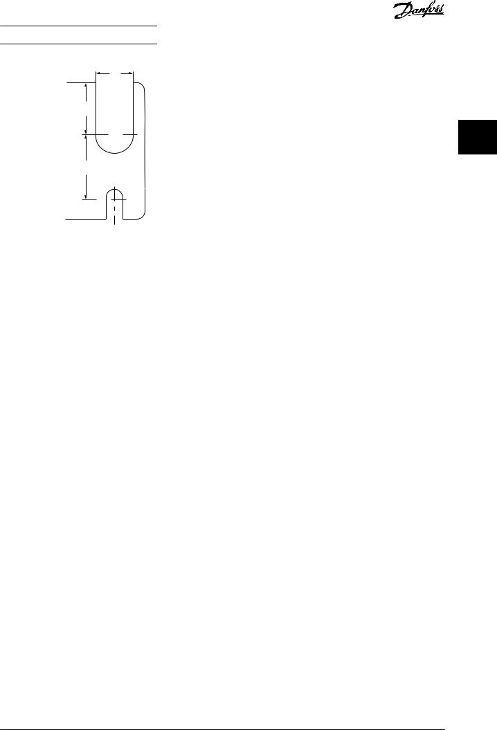
Illustration 1.3 is a block diagram of the internal |
|||||||||||||||||||||||||||||||||||||||||||||||||||||||||||||||||||||
|
|
components of the frequency converter. |
|||||||||||||||||||||||||||||||||||||||||||||||||||||||||||||||||||||
|
|
||||||||||||||||||||||||||||||||||||||||||||||||||||||||||||||||||||||
|
|
|
|
|
|
|
|
|
|
|
|
|
|
|
|
|
|
|
|
|
|
|
|
|
|
|
|
|
|
|
|
|
|
|
|
|
|
|
|
|
|
|
|
|
|
|
|
|
|
|
|
|
|
|
|
|
|
|
|
|
|
|
|
|
|
|
|
|
|
|
|
|
|
|
|
|
|
|
|
|
|
|
|
|
|
|
|
|
|
|
|
|
|
|
|
|
|
|
|
|
|
|
|
|
|
|
|
|
|
|
|
|
|
|
|
|
|
|
|
|
|
|
|
|
|
|
|
|
|
|
|
|
|
|
|
|
|
|
|
|
|
|
|
|
|
|
|
|
|
|
|
|
|
|
|
|
|
|
|
|
|
|
|
|
|
|
|
|
|
|
|
|
|
|
|
|
|
|
|
|
|
|
|
|
|
|
|
|
|
|
|
|
|
|
|
|
|
|
|
|
|
|
|
|
|
|
|
|
|
|
|
|
|
|
|
|
|
|
|
|
|
|
|
|
|
|
|
|
|
|
|
|
|
|
|
|
|
|
|
|
|
|
|
|
|
|
|
|
|
|
|
|
|
|
|
|
|
|
|
|
|
|
|
|
|
|
|
|
|
|
|
|
|
|
|
|
|
|
|
|
|
|
|
|
|
|
|
|
|
|
|
|
|
|
|
|
|
|
|
|
|
|
|
|
|
|
|
|
|
|
|
|
|
|
|
|
|
|
|
|
|
|
|
|
|
|
|
|
|
|
|
|
|
|
|
|
|
|
|
|
|
|
|
|
|
|
|
|
|
|
|
|
|
|
|
|
|
|
|
1.4.4 Enclosure Sizes and Power Ratings
For enclosure sizes and power ratings of the frequency converters, refer to chapter 8.9 Power Ratings, Weight, and Dimensions.
1.5 Approvals and Certi€cations
Area |
Title |
|
Functions |
|
|
|
|
|
|
1 |
Mains input |
• |
3-phase AC mains supply to the |
|
|
frequency converter. |
|||
|
|
|
||
|
|
|
|
|
|
|
• |
The recti€er bridge converts the |
|
2 |
Recti€er |
|
AC input to DC current to supply |
|
|
|
|
inverter power. |
|
|
|
|
|
|
3 |
DC bus |
• |
The intermediate DC bus circuit |
|
|
handles the DC current. |
|||
|
|
|
||
|
|
|
|
|
|
|
• |
Filter the intermediate DC circuit |
|
|
|
|
voltage. |
|
|
|
• |
Prove mains transient protection. |
|
4 |
DC reactors |
• |
Reduce RMS current. |
|
• |
Raise the power factor reflected |
|||
|
|
|||
|
|
|
back to the line. |
|
|
|
• |
Reduce harmonics on the AC |
|
|
|
|
input. |
|
|
|
|
|
|
|
|
• |
Stores the DC power. |
|
5 |
Capacitor bank |
• |
Provides ride-through protection |
|
|
|
|
for short power losses. |
|
|
|
|
|
|
|
|
• |
Converts the DC into a controlled |
|
6 |
Inverter |
|
PWM AC waveform for a |
|
|
controlled variable output to the |
|||
|
|
|
||
|
|
|
motor. |
|
|
|
|
|
|
7 |
Output to motor |
• |
Regulated 3-phase output power |
|
to the motor. |
||||
|
|
|
||
|
|
|
|
|
|
|
• |
Input power, internal processing, |
|
|
|
|
output, and motor current are |
|
|
|
|
monitored to provide efficient |
|
|
|
|
operation and control. |
|
8 |
Control circuitry |
• |
User interface and external |
|
|
|
|
commands are monitored and |
|
|
|
|
performed. |
|
|
|
• |
Status output and control can be |
|
|
|
|
provided. |
|
|
|
|
|
Illustration 1.3 Frequency Converter Block Diagram
Table 1.2 Approvals and Certi•cations
More approvals and certi€cations are available. Contact the local Danfoss partner. Frequency converters of enclosure size T7 (525–690 V) are UL certi€ed for only 525–600 V.
The frequency converter complies with UL 508C thermal memory retention requirements. For more information, refer to the section Motor Thermal Protection in the product-speci€c design guide.
For compliance with the European Agreement concerning International Carriage of Dangerous Goods by Inland Waterways (ADN), refer to ADN-compliant Installation in the product-speci€c design guide.
1.6 Disposal
Do not dispose of equipment containing electrical components together with domestic waste.
Collect it separately in accordance with local and currently valid legislation.
8 |
Danfoss A/S © 10/2016 All rights reserved. |
MG20MD02 |

Safety |
Operating Guide |
|
|
2 Safety
2.1 Safety Symbols
The following symbols are used in this guide:

 WARNING
Indicates a potentially hazardous situation that could result in death or serious injury.

 CAUTION
Indicates a potentially hazardous situation that could result in minor or moderate injury. It can also be used to alert against unsafe practices.
NOTICE
Indicates important information, including situations that can result in damage to equipment or property.
2.2 Quali€ed Personnel
Correct and reliable transport, storage, installation, operation, and maintenance are required for the troublefree and safe operation of the frequency converter. Only quali€ed personnel are allowed to install and operate this equipment.
Quali€ed personnel are de€ned as trained staff, who are authorized to install, commission, and maintain equipment, systems, and circuits in accordance with pertinent laws and regulations. Also, the quali€ed personnel must be familiar with the instructions and safety measures described in this manual.
2.3 Safety Precautions

 WARNING
HIGH VOLTAGE
Frequency converters contain high voltage when connected to AC mains input, DC supply, or load sharing. Failure to perform installation, start-up, and maintenance by quali•ed personnel can result in death or serious injury.
•Only quali•ed personnel must perform installation, start-up, and maintenance.
2 2

 WARNING
UNINTENDED START
When the frequency converter is connected to AC mains, DC supply, or load sharing, the motor may start at any time. Unintended start during programming, service, or repair work can result in death, serious injury, or property damage. The motor can start via an external switch, a •eldbus command, an input reference signal from the LCP, or after a cleared fault condition.
To prevent unintended motor start:
•Disconnect the frequency converter from the mains.
•Press [Off/Reset] on the LCP before programming parameters.
•Completely wire and assemble the frequency converter, motor, and any driven equipment before connecting the frequency converter to AC mains, DC supply, or load sharing.

 WARNING
DISCHARGE TIME
The frequency converter contains DC-link capacitors, which can remain charged even when the frequency converter is not powered. High voltage can be present even when the warning LED indicator lights are off. Failure to wait the speci•ed time after power has been removed before performing service or repair work can result in death or serious injury.
•Stop the motor.
•Disconnect AC mains and remote DC-link power supplies, including battery back-ups, UPS, and DC-link connections to other frequency converters.
•Disconnect or lock PM motor.
•Wait for the capacitors to discharge fully. The minimum duration of waiting time is speci•ed in Table 2.1.
•Before performing any service or repair work, use an appropriate voltage measuring device to make sure that the capacitors are fully discharged.
MG20MD02 |
Danfoss A/S © 10/2016 All rights reserved. |
9 |

|
|
|
|
Safety |
|
|
VLT® AQUA Drive FC 202 |
|
|
|
|
|
|
|
|
|
|
|
|
|
|
Voltage [V] |
Minimum waiting time (minutes) |
|
||
|
|
|
|
|
|
|
|
|
2 |
|
2 |
|
|
4 |
7 |
15 |
|
|
|
|
|
|
|
|
||
200–240 |
0.25–3.7 kW |
– |
5.5–45 kW |
|
||||
|
|
|
|
|
||||
|
|
|
|
|
(0.34–5 hp) |
|
(7.5–60 hp) |
|
|
|
|
|
|
|
|
|
|
|
|
|
|
380–480 |
0.37–7.5 kW |
– |
11–90 kW |
|
|
|
|
|
|
(0.5–10 hp) |
|
(15–121 hp) |
|
|
|
|
|
|
|
|
|
|
|
|
|
|
525–600 |
0.75–7.5 kW |
– |
11–90 kW |
|
|
|
|
|
|
(1–10 hp) |
|
(15–121 hp) |
|
|
|
|
|
|
|
|
|
|
|
|
|
|
525–690 |
– |
1.1–7.5 kW |
11–90 kW |
|
|
|
|
|
|
|
(1.5–10 hp) |
(15–121 hp) |
|
|
|
|
|
|
|
|
|
|
Table 2.1 Discharge Time

 WARNING
LEAKAGE CURRENT HAZARD
Leakage currents exceed 3.5 mA. Failure to ground the frequency converter properly can result in death or serious injury.
•Ensure the correct grounding of the equipment by a certi•ed electrical installer.

 WARNING
EQUIPMENT HAZARD
Contact with rotating shafts and electrical equipment can result in death or serious injury.
•Ensure that only trained and quali•ed personnel perform installation, start-up, and maintenance.
•Ensure that electrical work conforms to national and local electrical codes.
•Follow the procedures in this guide.

 WARNING
UNINTENDED MOTOR ROTATION WINDMILLING
Unintended rotation of permanent magnet motors creates voltage and can charge the unit, resulting in death, serious injury, or equipment damage.
•Ensure that permanent magnet motors are blocked to prevent unintended rotation.

 CAUTION
INTERNAL FAILURE HAZARD
An internal failure in the frequency converter can result in serious injury when the frequency converter is not properly closed.
•Ensure that all safety covers are in place and securely fastened before applying power.
10 |
Danfoss A/S © 10/2016 All rights reserved. |
MG20MD02 |

Mechanical Installation |
Operating Guide |
|
|
3 Mechanical Installation
3.1 Unpacking
3.1.1 Items Supplied
Items supplied may vary according to product con€guration.
3.1.2 Storage
Ensure that the requirements for storage are ful€lled. Refer |
3 |
3 |
to chapter 8.4 Ambient Conditions for further details.
3.2 Installation Environments
•Make sure the items supplied and the information on the nameplate correspond to the order con€r- mation.
•Check the packaging and the frequency converter visually for damage caused by inappropriate handling during shipment. File any claim for damage with the carrier. Retain damaged parts for clari€cation.
2 |
VLT |
R |
AQUA Drive |
3 |
<![if ! IE]> <![endif]>130BD666.10 |
|
1 |
|
www.danfoss.com |
|
|
||
T/C: FC-202P45KT4E20H1XGXXXXSXXXXAXBXCXXXXDX |
|
|
||||
|
|
|
||||
4 |
P/N: 131F6653 |
S/N: 038010G502 |
|
|
||
45kW(400V) / 60HP(460V) |
|
|
||||
5 |
9 |
|
||||
IN: 3x380-480V 50/60Hz 82/73A |
|
|||||
6 |
|
|
||||
OUT: 3x0-Vin 0-590Hz 90/80A |
|
|
||||
7 |
8 |
|
||||
CHASSIS/ IP20 Tamb.45o C/113o F |
|
|||||
|
|
|||||
|
MADE IN |
* 1 3 1 F 6 6 5 3 0 3 8 0 1 0 G 5 0 2 * |
DENMARK |
|
|
|
|
Listed 76X1 E134261 Ind. Contr. Eq. |
|
CAUTION:
See manual for special condition/mains fuse
10voir manual de conditions speclales/fusibles`
WARNING:
Stored charge, wait 15 min. Charge residuelle,` attendez 15 min.
NOTICE
In environments with airborne liquids, particles, or corrosive gases, ensure that the IP/type rating of the equipment matches the installation environment. Failure to meet requirements for ambient conditions can reduce the lifetime of the frequency converter. Ensure that requirements for air humidity, temperature, and altitude are met.
Vibration and shock
The frequency converter complies with requirements for units mounted on the walls and floors of production premises, and in panels bolted to walls or floors.
For detailed ambient conditions speci€cations, refer to chapter 8.4 Ambient Conditions.
1 |
Type code |
|
|
|
|
2 |
Ordering number |
|
|
|
|
3 |
Serial number |
|
|
|
|
4 |
Power rating |
|
|
|
|
5 |
Input voltage, frequency, and current (at low/high |
|
voltages) |
||
|
||
|
|
|
6 |
Output voltage, frequency, and current (at low/high |
|
voltages) |
||
|
||
|
|
|
7 |
Enclosure type and IP rating |
|
|
|
|
8 |
Maximum ambient temperature |
|
|
|
|
9 |
Certi€cations |
|
|
|
|
10 |
Discharge time (Warning) |
|
|
|
Illustration 3.1 Product Nameplate (Example)
NOTICE
Do not remove the nameplate from the frequency converter. Removing the nameplate voids the warranty.
MG20MD02 |
Danfoss A/S © 10/2016 All rights reserved. |
11 |

Mechanical Installation |
VLT® AQUA Drive FC 202 |
3.3 Mounting
NOTICE
Improper mounting can result in overheating and reduced performance.
3 3 Cooling
•Ensure that top and bottom clearance for air cooling is provided. See Illustration 3.2 for clearance requirements.
a |
<![if ! IE]> <![endif]>130BD528.10 |
a
Enclosure |
A2–A5 |
B1–B4 |
C1, C3 |
C2, C4 |
|
|
|
|
|
a [mm (in)] |
100 (3.9) |
200 (7.9) |
200 (7.9) |
225 (8.9) |
|
|
|
|
|
Illustration 3.2 Top and Bottom Cooling Clearance
Lifting
•To determine a safe lifting method, check the weight of the unit, see chapter 8.9 Power Ratings, Weight, and Dimensions.
•Ensure that the lifting device is suitable for the task.
•If necessary, plan for a hoist, crane, or forklift with the appropriate rating to move the unit.
•For lifting, use the hoist rings on the unit, when provided.
Mounting
1.Ensure that the strength of the mounting location supports the unit weight. The frequency converter allows side-by-side installation.
2.Locate the unit as near to the motor as possible. Keep the motor cables as short as possible.
3.Mount the unit vertically to a solid flat surface or to the optional backplate to provide cooling airflow.
4.Use the slotted mounting holes on the unit for wall mounting, when provided.
Mounting with backplate and railings
<![if ! IE]><![endif]>
 130BD504.10
Illustration 3.3 Proper Mounting with Backplate
NOTICE
A backplate is required when mounted on railings.
|
B |
|
b |
|
|
<![if ! IE]> <![endif]>130BA648.12 |
C |
|
|
e |
|
||
|
|
|
|
|||
|
|
|
|
|
||
|
|
|
|
|
f |
|
|
|
c |
|
|
a |
|
|
|
|
|
|
|
A
 d
d
e
a
b
Illustration 3.4 Top and Bottom Mounting Holes (See chapter 8.9 Power Ratings, Weight, and Dimensions)
12 |
Danfoss A/S © 10/2016 All rights reserved. |
MG20MD02 |
Mechanical Installation
e
f
a
Operating Guide
<![if ! IE]><![endif]>130BA715.12
3 3
Illustration 3.5 Top and Bottom Mounting Holes (B4, C3, and
C4)
MG20MD02 |
Danfoss A/S © 10/2016 All rights reserved. |
13 |

Electrical Installation |
VLT® AQUA Drive FC 202 |
4 Electrical Installation
4.1 Safety Instructions
See chapter 2 Safety for general safety instructions.
|
|
|
|
4 |
4 |
WARNING |
|
INDUCED VOLTAGE |
|||
|
|
Induced voltage from output motor cables that run together can charge equipment capacitors, even with the equipment turned off and locked out. Failure to run output motor cables separately or to use shielded cables could result in death or serious injury.
•Run output motor cables separately, or
•Use shielded cables.

 CAUTION
SHOCK HAZARD
The frequency converter can cause a DC current in the PE conductor. Failure to follow the recommendation may lead to the RCD not providing the intended protection.
•When a residual current-operated protective device (RCD) is used for protection against electrical shock, only an RCD of Type B is allowed on the supply side.
Overcurrent protection
•Extra protective equipment, such as short-circuit protection or motor thermal protection between frequency converter and motor, is required for applications with multiple motors.
•Input fusing is required to provide short circuit and overcurrent protection. If not factorysupplied, the installer must provide fuses. See maximum fuse ratings in chapter 8.8 Fuses and Circuit Breakers.
Wire type and ratings
•All wiring must comply with local and national regulations regarding cross-section and ambient temperature requirements.
•Power connection wire recommendation: Minimum 75 °C (167 °F) rated copper wire.
See chapter 8.1 Electrical Data and chapter 8.5 Cable Specifications for recommended wire sizes and types.
4.2 EMC-compliant Installation
To obtain an EMC-compliant installation, follow the instructions provided in chapter 4.3 Grounding,
chapter 4.4 Wiring Schematic, chapter 4.6 Motor Connection, and chapter 4.8 Control Wiring.
4.3 Grounding

 WARNING
LEAKAGE CURRENT HAZARD
Leakage currents exceed 3.5 mA. Failure to ground the frequency converter properly could result in death or serious injury.
•Ensure the correct grounding of the equipment by a certi•ed electrical installer.
For electrical safety
•Ground the frequency converter in accordance with applicable standards and directives.
•Use a dedicated ground wire for input power, motor power, and control wiring.
•Do not ground 1 frequency converter to another in a daisy-chain fashion (see Illustration 4.1).
•Keep the ground wire connections as short as possible.
•Follow motor manufacturer wiring requirements.
•Minimum cable cross-section: 10 mm2 (7 AWG). Separately terminate 2 ground wires, both complying with the dimension requirements.
<![if ! IE]><![endif]>130BC500.10
|
|
|
|
|
|
|
|
|
FC 1 |
|
|
FC 2 |
|
|
FC 3 |
|
|
|
|
|
|
|
|
PE
|
|
|
|
|
|
|
|
|
|
|
|
|
|
|
|
|
|
|
|
|
|
|
|
|
|
|
|
|
|
|
|
|
|
|
|
|
|
|
|
|
|
|
|
|
|
|
|
|
|
|
|
|
|
|
|
|
|
|
|
|
|
|
|
|
|
|
|
|
|
|
|
|
|
|
|
|
|
|
|
|
|
|
|
|
|
|
|
|
|
|
|
|
|
|
|
|
|
|
|
|
|
|
|
|
|
|
|
|
|
|
|
|
|
|
|
|
|
|
|
|
|
|
|
|
|
|
|
|
|
|
|
|
|
|
|
|
|
|
|
|
|
|
|
|
|
|
|
|
|
|
|
|
|
|
|
|
|
|
|
|
|
|
|
FC 1 |
|
|
|
|
FC 2 |
|
|
|
|
FC 3 |
|||||||||
|
|
|
|
|
|
|
|
|
|
|
|
|
|
|
|
|
|
|
|
|
|
|
|
|
|
|
|
|
|
|
|
|
|
|
|
|
|
|
|
|
|
|
|
|
|
|
|
|
|
|
|
|
|
|
|
|
|
|
|
|
|
|
|
|
|
|
|
|
PE
Illustration 4.1 Grounding Principle
14 |
Danfoss A/S © 10/2016 All rights reserved. |
MG20MD02 |

Electrical Installation |
Operating Guide |
|
||||
|
|
|
|
|
||
|
For EMC-compliant installation |
|
|
|
||
|
• |
Establish electrical contact between the cable |
|
|||
|
|
shield and the frequency converter enclosure by |
|
|||
|
|
using metal cable glands or by using the clamps |
|
|||
|
|
provided on the equipment (see chapter 4.6 Motor |
|
|||
|
|
Connection). |
|
|
|
|
|
• |
Use high-strand wire to reduce burst transient. |
|
|||
|
• |
Do not use pigtails. |
4 |
4 |
||
|
|
|
||||
NOTICE |
||||||
POTENTIAL EQUALIZATION
Risk of burst transient when the ground potential between the frequency converter and the control system is different. Install equalizing cables between the system components. Recommended cable cross-section: 16 mm2 (6 AWG).
MG20MD02 |
Danfoss A/S © 10/2016 All rights reserved. |
15 |
Electrical Installation |
VLT® AQUA Drive FC 202 |
4.4 Wiring Schematic
|
3-phase |
91 |
(L1) |
|
92 |
(L2) |
|
|
power |
||
|
93 |
(L3) |
|
|
input |
||
|
95 |
PE |
|
|
|
||
4 |
DC bus |
88 (-) |
|
4 |
89 |
(+) |
|
|
|
||
+10 V DC |
50 |
(+10 V OUT) |
||
|
|
A53 |
||
0/-10 V DC- |
|
|
||
53 |
(A IN) |
<![if ! IE]> <![endif]>1 |
||
+10 V DC |
<![if ! IE]> <![endif]>2 |
|||
|
|
|||
0/4-20 mA |
|
|
A54 |
|
0/-10 V DC - |
54 |
(A IN) |
<![if ! IE]> <![endif]>1 |
|
| <![if ! IE]> <![endif]>2 |
||||
+10 V DC |
|
|
||
|
|
|
||
0/4-20 mA |
|
|
|
|
55 (COM A IN)
 12 (+24 V OUT)
  13 (+24 V OUT)
 18 (D IN)
 19 (D IN)
 20 (COM D IN)
  27 (D IN/OUT)
 29 (D IN/OUT)
 32 (D IN)
  33 (D IN)
*
37 (D IN)
|
|
|
|
|
|
|
|
(U) 96 |
|
|
|
|
|
|
|
|
|
(V) 97 |
|
|
|
|
|
|
|
|
|
(W) 98 |
|
|
|
|
|
|
|
|
|
(PE) 99 |
|
|
|
Switch Mode |
|
|
|
|
|
||
|
|
Power Supply |
|
|
|
|
|
||
|
|
10 V DC |
|
24 V DC |
|
|
|
(R+) 82 |
|
|
|
15 mA |
|
200 mA |
|
|
|
|
|
|
|
+ - |
+ |
- |
|
|
|
(R-) 81 |
|
|
|
|
|
|
|
|
|
|
|
| <![if ! IE]> <![endif]>ON |
ON=0/4-20 mA |
|
|
|
|
|
relay1 |
|
|
|
|
|
|
|
|
|
|||
|
|
|
|
|
|
03 |
|
||
|
OFF=0/-10 V DC - |
|
|
|
|
|
|
||
| <![if ! IE]> <![endif]>ON |
|
|
|
|
|
|
|
||
|
+10 V DC |
|
|
|
|
|
02 |
|
|
|
|
|
|
|
|
|
|
||
|
|
|
|
|
|
|
|
|
|
|
|
|
|
|
|
|
|
01 |
|
|
|
|
|
|
|
|
|
relay2 |
|
|
|
|
|
|
|
|
|
06 |
|
|
|
P 5-00 |
|
|
|
|
|
05 |
|
|
|
24 V (NPN) |
|
|
|
04 |
|
||
|
|
0 V (PNP) |
|
|
|
|
|||
|
|
|
|
|
|
|
|||
|
|
24 V (NPN) |
|
|
|
(COM A OUT) 39 |
|
||
|
|
0 V (PNP) |
|
|
|
|
|||
|
|
|
|
|
|
|
|||
|
|
|
|
|
|
|
|
(A OUT) 42 |
|
|
|
24 V (NPN) |
S801 |
|
|
|
|
||
|
24 V |
0 V (PNP) |
|
ON=Terminated |
|
||||
|
|
|
|
<![if ! IE]> <![endif]>2 1 |
<![if ! IE]> <![endif]>ON |
|
|||
|
|
|
|
|
OFF=Open |
|
|||
|
0 V |
|
|
|
5V |
|
|
|
|
|
|
24 V (NPN) |
|
|
|
|
|
||
|
24 V |
0 V (PNP) |
|
|
|
|
|
||
|
|
|
|
|
|
|
|
|
|
|
|
|
|
|
|
S801 |
0 V |
|
|
|
|
|
|
|
|
|
|
||
|
0 V |
|
|
|
RS-485 |
|
|
|
|
|
|
|
|
|
|
(N RS-485) 69 |
|
||
|
|
24 V (NPN) |
Interface |
|
|
||||
|
|
|
|
|
|||||
|
|
0 V (PNP) |
|
|
|
(P RS-485) 68 |
|
||
|
|
24 V (NPN) |
|
|
|
(COM RS-485) 61 |
** |
||
|
|
0 V (PNP) |
|
|
|
|
|||
|
|
|
|
|
|
|
|||
Motor
Brake resistor
240 V AC, 2 A
240 V AC, 2 A
400 V AC, 2 A
Analog Output 0/4-20 mA
RS-485


 : Chassis
 : Ground
 : PE
: PE
: Ground
: Ground
<![endif]>130BD552.12
1
2
Illustration 4.2 Basic Wiring Schematic
A=Analog, D=Digital
*Terminal 37 (optional) is used for Safe Torque Off. For Safe Torque Off installation instructions, refer to the VLT® Frequency Converters - Safe Torque Off Operating Guide.
**Do not connect cable shield.
NOTICE
Actual con•gurations vary with unit types and optional equipment.
16 |
Danfoss A/S © 10/2016 All rights reserved. |
MG20MD02 |
Electrical Installation |
Operating Guide |
|
|
|
2 |
|
<![if ! IE]> <![endif]>130BD529.12 |
|
|
|
|
|
|
1 |
|
3 |
4 |
4 |
|
|
|
||
|
|
|
|
|
|
|
4 |
|
|
|
|
|
5 |
|
|
|
u |
|
|
|
|
v |
|
|
9 |
|
w |
|
|
|
|
|
|
|
10 |
11 |
PE |
|
|
L1 |
|
|
|
|
L2 |
|
|
|
|
L3 |
|
|
|
|
PE |
|
|
|
|
|
8 |
|
|
|
|
6 |
|
|
|
|
|
7 |
|
|
1 |
PLC |
6 |
Cable gland |
|
|
|
|
2 |
Frequency converter |
7 |
Motor, 3-phase, and PE |
|
|
|
|
3 |
Output contactor |
8 |
Mains, 3-phase, and reinforced PE |
|
|
|
|
4 |
Grounding rail (PE) |
9 |
Control wiring |
|
|
|
|
5 |
Cable insulation (stripped) |
10 |
Equalizing minimum 16 mm2 (5 AWG) |
Illustration 4.3 EMC-compliant Connection of Mains
NOTICE
EMC INTERFERENCE
Use shielded cables for motor and control wiring and separate cables for input power, motor wiring, and control wiring. Failure to isolate power, motor, and control cables can result in unintended behavior or reduced performance. Minimum clearance requirement between power, motor, and control cables is 200 mm (7.9 in).
MG20MD02 |
Danfoss A/S © 10/2016 All rights reserved. |
17 |

4 4
Electrical Installation |
VLT® AQUA Drive FC 202 |
4.5Access
1.Remove the cover with a screwdriver (See Illustration 4.4) or by loosening the attaching screws (See Illustration 4.5).
<![if ! IE]><![endif]>130BT248.10
Illustration 4.4 Access to Wiring for IP20 and IP21 Enclosures
<![if ! IE]><![endif]>


 130BT334.10
Illustration 4.5 Access to Wiring for IP55 and IP66 Enclosures
Tighten the cover screws using the tightening torques speci€ed in Table 4.1.
Enclosure |
IP55 |
IP66 |
||
|
|
|
||
A4/A5 |
2 (18) |
2 (18) |
||
|
|
|
|
|
B1/B2 |
2.2 |
(19) |
2.2 |
(19) |
|
|
|
|
|
C1/C2 |
2.2 |
(19) |
2.2 |
(19) |
|
|
|
|
|
No screws to tighten for A2/A3/B3/B4/C3/C4.
Table 4.1 Tightening Torques for Covers [N•m (in-lb)]
4.6 Motor Connection

 WARNING
INDUCED VOLTAGE
Induced voltage from output motor cables that run together can charge equipment capacitors, even with the equipment turned off and locked out. Failure to run output motor cables separately or use shielded cables could result in death or serious injury.
•Run output motor cables separately, or
•Use shielded cables.
•Comply with local and national electrical codes for cable sizes. For maximum wire sizes, see chapter 8.1 Electrical Data.
•Follow motor manufacturer wiring requirements.
•Motor wiring knockouts or access panels are provided at the base of IP21 (NEMA1/12) and higher units.
•Do not wire a starting or pole-changing device (for example Dahlander motor or slip ring asynchronous motor) between the frequency converter and the motor.
Procedure
1.Strip a section of the outer cable insulation.
2.Position the stripped wire under the cable clamp to establish mechanical €xation and electrical contact between the cable shield and ground.
3.Connect the ground wire to the nearest grounding terminal in accordance with the grounding instructions provided in chapter 4.3 Grounding, see Illustration 4.6.
4.Connect the 3-phase motor wiring to terminals 96 (U), 97 (V), and 98 (W), see Illustration 4.6.
5.Tighten the terminals in accordance with the information provided in chapter 8.7 Connection Tightening Torques.
18 |
Danfoss A/S © 10/2016 All rights reserved. |
MG20MD02 |

Electrical Installation |
|
|
Operating Guide |
|
|
W |
<![if ! IE]> <![endif]>130BD531.10 |
|
|
|
|
|
V |
98 |
|
U |
|
|
|
97 |
|
||
|
|
||
96 |
|
|
|
Illustration 4.6 Motor Connection
Illustration 4.7 shows mains input, motor, and grounding for basic frequency converters. Actual con€gurations vary with unit types and optional equipment.
|
|
|
|
M |
|
|
|
|
S |
<![if ! IE]> <![endif]>130BF948.10 |
|
|
|
L1 |
|
|
A |
|
|
|
|
||
|
|
|
|
|
|
I |
|
|
|
||
|
|
L2 |
|
|
|
|
N |
|
|
||
|
91 |
|
|
|
|
|
|
|
|
||
|
92 |
L3 |
|
|
|
|
|
|
|||
|
|
|
|
|
|
|
|
||||
|
|
|
|
|
|
|
|
|
|||
|
|
93 |
|
|
|
|
|
|
<![if ! IE]> <![endif]>2 |
||
|
|
|
|
|
|
|
|
|
|||
|
|
|
|
|
|
|
|
|
|
|
<![if ! IE]> <![endif]>RELAY |
|
|
|
|
|
|
|
|
|
|
|
<![if ! IE]> <![endif]>RELAY 1 |
|
|
+DC |
BR- |
|
|
|
|
|
|
|
|
|
|
|
B |
|
|
|
|
|
|
||
|
|
|
|
|
|
|
|
|
|
|
|
|
|
|
|
O |
|
|
|
|
|
||
99 |
|
|
M |
|
|
|
|
|
|
|
|
|
U |
|
|
T |
|
|
|
||||
|
|
|
|
V |
OR |
|
|
||||
|
|
|
|
W |
|
|
|
||||
|
|
|
|
|
|
|
|
|
|
||
|
|
|
99 |
|
|
|
|
|
|||
Illustration 4.7 Example of Motor, Mains, and Ground Wiring
4.7AC Mains Connection
•Size the wiring based on the input current of the frequency converter. For maximum wire sizes, see chapter 8.1 Electrical Data.
•Comply with local and national electrical codes for cable sizes.
Procedure
1. Connect the 3-phase AC input power wiring to 4 4 terminals L1, L2, and L3 (see Illustration 4.7).
2.Depending on the con€guration of the equipment, connect the input power to the mains input terminals or the input disconnect.
3.Ground the cable in accordance with the grounding instructions provided in chapter 4.3 Grounding.
4.When supplied from an isolated mains source (IT mains or floating delta) or TT/TN-S mains with a grounded leg (grounded delta), ensure that parameter 14-50 RFI Filter is set to [0] Off to avoid damage to the DC link and to reduce ground capacity currents in accordance with IEC 61800-3.
4.8Control Wiring
•Isolate the control wiring from the high-power components in the frequency converter.
•When the frequency converter is connected to a thermistor, ensure that the thermistor control wiring is shielded and reinforced/double insulated. A 24 V DC supply voltage is recommended. See Illustration 4.8.
4.8.1 Control Terminal Types
Illustration 4.8 and Illustration 4.9 show the removable frequency converter connectors. Terminal functions and default settings are summarized in Table 4.2.
<![if ! IE]><![endif]>130BB921.12
2 |
|
3 |
4 |
|


 1
1

Illustration 4.8 Control Terminal Locations
MG20MD02 |
Danfoss A/S © 10/2016 All rights reserved. |
19 |

Electrical Installation |
VLT® AQUA Drive FC 202 |
|
|
|
1 |
|
|
|
<![if ! IE]> <![endif]>130BB931.11 |
|
Terminal description |
||
|
|
|
|
|
|
|
|
|
Default |
|
|
|
|
|
|
|
|
|
|
|
|
|
|
|
|
|
12 13 18 19 27 29 32 33 20 37 |
|
Terminal |
Parameter |
setting |
Description |
|||
|
|
|
|
|
|
|
|
|
Parameter 5 |
|
|
|
|
|
|
|
|
|
|
|
-10 Termina |
|
|
|
|
|
2 |
|
3 |
|
|
|
l 18 Digital |
|
|
|
|
|
|
|
|
|
|
18 |
Input |
[8] Start |
|
|
|
|
61 68 69 |
39 42 50 53 54 55 |
|
19 |
Parameter 5 |
|
|
||
4 |
4 |
|
|
|
-11 Termina |
|
|
||||
|
|
|
|
|
|
|
|
|
|||
|
|
|
|
|
|
|
l 19 Digital |
[0] No |
|
||
|
Illustration 4.9 Terminal Numbers |
|
|
|
Input |
operation |
|
||||
|
|
|
|
|
|
|
|
|
Digital inputs. |
||
|
|
|
|
|
|
|
|
32 |
Parameter 5 |
|
|
|
|
|
|
|
|
|
|
|
|
||
|
• |
Connector 1 provides: |
|
|
|
-14 Termina |
|
|
|||
|
|
|
|
l 32 Digital |
[0] No |
|
|||||
|
|
|
- |
4 programmable digital inputs terminals. |
|
Input |
operation |
|
|||
|
|
|
- |
2 extra digital terminals programmable |
33 |
Parameter 5 |
|
|
|||
|
|
|
|
-15 Termina |
|
|
|||||
|
|
|
|
as either input or output. |
|
|
|
||||
|
|
|
|
|
l 33 Digital |
[0] No |
|
||||
|
|
|
- |
24 V DC terminal supply voltage. |
|
|
|||||
|
|
|
|
Input |
operation |
|
|||||
|
|
|
|
|
|
|
|
|
|
||
|
|
|
- |
Optional customer supplied 24 V DC |
27 |
Parameter 5 |
|
|
|||
|
|
|
|
voltage. |
|
|
|
-12 Termina |
|
|
|
|
• |
Connector 2 terminals (+)68 and (-)69 are for an |
|
l 27 Digital |
[2] Coast |
For digital input or |
|||||
|
|
Input |
inverse |
||||||||
|
|
RS485 serial communication connection. |
|
output. Default setting |
|||||||
|
|
29 |
Parameter 5 |
[14] Jog |
|||||||
|
• |
Connector 3 provides: |
|
|
is input. |
||||||
|
|
|
|
-13 Termina |
|
||||||
|
|
|
|
|
|
||||||
|
|
|
- |
2 analog inputs. |
|
|
|
l 29 Digital |
|
|
|
|
|
|
- |
1 analog output. |
|
|
|
Input |
|
|
|
|
|
|
|
|
20 |
– |
– |
Common for digital |
|||
|
|
|
- |
10 V DC supply voltage. |
|||||||
|
|
|
|
|
|
inputs and 0 V |
|||||
|
|
|
- |
Commons for the inputs and output. |
|
|
|
potential for 24 V |
|||
|
• |
Connector 4 is a USB port available for use with |
|
|
|
supply. |
|||||
|
37 |
– |
Safe Torque |
Safe input (optional). |
|||||||
|
|
the MCT 10 Set-up Software. |
|
||||||||
|
|
|
|
|
Off (STO) |
Used for STO. |
|||||
|
|
|
|
|
|
|
|
|
|
||
|
|
|
|
Terminal description |
|
|
Analog Inputs/Outputs |
||||
|
|
|
|
|
Default |
|
|
39 |
– |
– |
Common for analog |
|
Terminal |
Parameter |
setting |
|
Description |
|
|
output |
|||
|
|
|
|
|
|||||||
|
|
|
|
Digital Inputs/Outputs |
|
42 |
Parameter 6 |
Speed 0 – |
Programmable analog |
||
|
12, 13 |
|
– |
|
+24 V DC |
24 V DC supply voltage |
|
-50 Termina |
High Limit |
output. 0–20 mA or 4– |
|
|
|
|
|
l 42 Output |
|
20 mA at a maximum |
|||||
|
|
|
|
|
|
for digital inputs and |
|
|
|||
|
|
|
|
|
|
|
|
|
of 500 Ω |
||
|
|
|
|
|
|
external transducers. |
|
|
|
||
|
|
|
|
|
|
Maximum output |
50 |
– |
+10 V DC |
10 V DC analog supply |
|
|
|
|
|
|
|
current 200 mA for all |
|
|
|
voltage for potenti- |
|
|
|
|
|
|
|
24 V loads. |
|
|
|
ometer or thermistor. |
|
|
|
|
|
|
|
|
|
|
|
|
15 mA maximum |
|
|
|
|
|
|
|
|
|
Parameter |
|
|
|
|
|
|
|
|
|
|
|
group 6-1* |
|
|
|
|
|
|
|
|
|
|
|
Analog |
|
|
|
|
|
|
|
|
|
|
53 |
Input 53 |
Reference |
|
|
|
|
|
|
|
|
|
54 |
Parameter |
Feedback |
Analog input. For |
|
|
|
|
|
|
|
|
|
group 6-2* |
|
voltage or current. |
|
|
|
|
|
|
|
|
|
Analog |
|
Switches A53 and A54 |
|
|
|
|
|
|
|
|
|
Input 54 |
|
select mA or V. |
|
|
|
|
|
|
|
|
55 |
– |
– |
Common for analog |
|
|
|
|
|
|
|
|
|
|
input |
|
|
|
|
|
|
|
|
|
|
|
|
|
|
|
|
|
|
|
|
|
|
Serial Communication |
||
20 |
Danfoss A/S © 10/2016 All rights reserved. |
MG20MD02 |

Electrical Installation |
Operating Guide |
|
|
Terminal description
|
|
Default |
|
Terminal |
Parameter |
setting |
Description |
|
|
|
|
61 |
– |
– |
Integrated RC-Filter for |
|
|
|
cable shield. ONLY for |
|
|
|
connecting the shield if |
|
|
|
EMC problems occur. |
|
|
|
|
|
Parameter |
– |
|
|
group 8-3* |
|
|
|
FC Port |
|
RS485 Interface. A |
68 (+) |
Settings |
|
control card switch is |
|
|
|
provided for |
69 (-) |
Parameter |
– |
|
|
group 8-3* |
|
termination resistance. |
|
FC Port |
|
|
|
Settings |
|
|
|
|
|
|
|
|
Relays |
|
|
|
|
|
|
Parameter 5 |
|
|
|
-40 Functio |
|
Form C relay output. |
01, 02, 03 |
n Relay [0] |
[9] Alarm |
For AC or DC voltage |
|
|
|
and resistive or |
04, 05, 06 |
Parameter 5 |
[5] Running |
|
|
-40 Functio |
|
inductive loads. |
|
n Relay [1] |
|
|
|
|
|
|
Table 4.2 Terminal Description
Extra terminals
•2 form C relay outputs. Location of the outputs depends on frequency converter con€guration.
•Terminals on built-in optional equipment. See the manual provided with the equipment option.
4.8.2 Wiring to Control Terminals
Control terminal connectors can be unplugged from the frequency converter for ease of installation, as shown in
Illustration 4.10.
NOTICE
Keep control wires as short as possible and separate from high-power cables to minimize interference.
1.Open the contact by inserting a small screwdriver into the slot above the contact and push the screwdriver slightly upwards.
12 |
13 |
18 |
19 |
27 |
29 |
32 |
33 |
<![if ! IE]> <![endif]>130BD546.11 |
|
|
|||||||||
|
1 |
|
|
|
|
|
|
2 |
|
|
|
|
|
|
mm |
|
|
|
|
|
|
|
|
10 |
|
inches] |
|
|
|
|
|
|
|
[0 |
.4 |
|
|
||
|
|
|
|
|
|
|
|
||
|
|
|
|
|
|
|
|
|
|
Illustration 4.10 Connecting Control Wires
2.Insert the bare control wire into the contact.
3.Remove the screwdriver to fasten the control wire into the contact.
4.Ensure that the contact is €rmly established and not loose. Loose control wiring can be the source of equipment faults or less than optimal operation.
See chapter 8.5 Cable Specifications for control terminal wiring sizes and chapter 6 Application Set-up Examples for typical control wiring connections.
4.8.3Enabling Motor Operation (Terminal 27)
A jumper wire is required between terminal 12 (or 13) and terminal 27 for the frequency converter to operate when using factory default programming values.
•Digital input terminal 27 is designed to receive 24 V DC external interlock command.
•When no interlock device is used, wire a jumper between control terminal 12 (recommended) or 13 to terminal 27. The jumper provides an internal 24 V signal on terminal 27.
•When the status line at the bottom of the LCP reads AUTO REMOTE COAST, it indicates that the unit is ready to operate but is missing an input signal on terminal 27.
•When factory installed optional equipment is
wired to terminal 27, do not remove that wiring.
4 4
MG20MD02 |
Danfoss A/S © 10/2016 All rights reserved. |
21 |
Electrical Installation |
VLT® AQUA Drive FC 202 |
4.8.4Voltage/Current Input Selection (Switches)
The analog input terminals 53 and 54 allow setting of input signal to voltage (0–10 V) or current (0/4–20 mA).
Default parameter setting
|
|
|
• |
Terminal 53: Speed reference signal in open loop |
4 |
|
4 |
||
|
|
(see parameter 16-61 Terminal 53 Switch Setting). |
||
|
|
|
|
|
|
|
|
• |
Terminal 54: Feedback signal in closed loop (see |
|
|
|
|
parameter 16-63 Terminal 54 Switch Setting). |
NOTICE
Disconnect power to the frequency converter before changing switch positions.
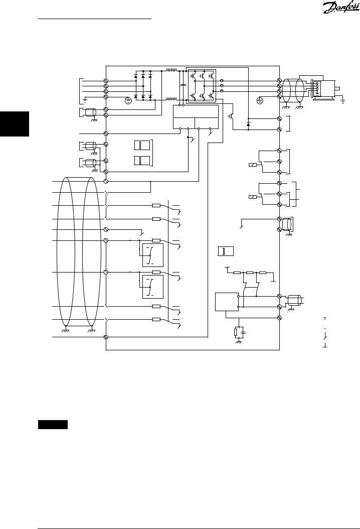
1.Remove the LCP (see Illustration 4.11).
2.Remove any optional equipment covering the switches.
3.Set switches A53 and A54 to select the signal type. U selects voltage, I selects current.
<![if ! IE]><![endif]>130BD530.10
| <![if ! IE]> <![endif]>1 |
<![if ! IE]> <![endif]>O |
| <![if ! IE]> <![endif]>2 |
<![if ! IE]> <![endif]>N |
BUSTER. |
A53 A54 |
||
OFF-ON |
|||
U- I |
U- I |
||
|
|||
VLT
Illustration 4.11 Location of Terminal 53 and 54 Switches
To run STO, more wiring for the frequency converter is required. Refer to VLT® Frequency Converters Safe Torque Off Operating Guide for further information.
4.8.5 RS485 Serial Communication
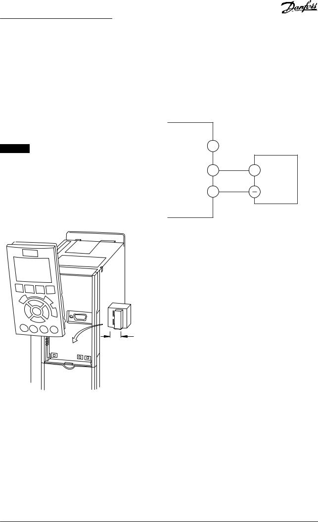
Connect RS485 serial communication wiring to terminals (+)68 and (-)69.
•Use shielded serial communication cable (recommended).
•See chapter 4.3 Grounding for proper grounding.
61 |
<![if ! IE]> <![endif]>130BB489.10 |
|
|
68 |
+ |
|
RS485 |
69 |
|
Illustration 4.12 Serial Communication Wiring Diagram
For basic serial communication set-up, select the following:
1.Protocol type in parameter 8-30 Protocol.
2.Frequency converter address in parameter 8-31 Address.
3.Baud rate in parameter 8-32 Baud Rate.
•2 communication protocols are internal to the frequency converter:
-Danfoss FC.
-Modbus RTU.
•Functions can be programmed remotely using the protocol software and RS485 connection or in parameter group 8-** Communications and Options.
•Selecting a speci€c communication protocol changes various default parameter settings to match that protocol’s speci€cations and makes more protocol-speci€c parameters available.
•Option cards for the frequency converter are available to provide extra communication protocols. See the option card documentation for installation and operation instructions.
22 |
Danfoss A/S © 10/2016 All rights reserved. |
MG20MD02 |

Electrical Installation |
Operating Guide |
|
|
4.9 Installation Check List
Before completing installation of the unit, inspect the entire installation as detailed in Table 4.3. Check and mark the items when completed.
Inspect for |
Description |
|
Auxiliary equipment |
• Look for auxiliary equipment, switches, disconnects, or input fuses/circuit breakers, residing on the input |
|
|
power side of the frequency converter, or output side to the motor. Ensure that they are ready for full- |
|
|
|
speed operation. |
4 |
4 |
|
|
|
|
|
|
• |
Check the function and installation of any sensors used for feedback to the frequency converter. |
|
|
|
• |
Remove any power factor correction caps on the motor. |
|
|
|
• |
Adjust any power factor correction caps on the mains side and ensure that they are dampened. |
|
|
|
|
|
|
|
Cable routing |
• |
Ensure that the motor wiring and control wiring are separated, shielded, or in 3 separate metallic conduits |
|
|
|
|
for high frequency interference isolation. |
|
|
|
|
|
|
|
Control wiring |
• |
Check for broken or damaged wires and loose connections. |
|
|
|
• |
Check that the control wiring is isolated from power and motor wiring for noise immunity. |
|
|
|
• |
Check the voltage source of the signals, if necessary. |
|
|
|
The use of shielded cable or twisted pair is recommended. Ensure that the shield is terminated correctly. |
|
|
|
|
|
|
|
|
Cooling clearance |
• |
Ensure that the top and bottom clearance is adequate to ensure proper airflow for cooling, see |
|
|
|
|
chapter 3.3 Mounting. |
|
|
|
|
|
|
|
Ambient conditions |
• |
Check that requirements for ambient conditions are met. |
|
|
|
|
|
|
|
Fusing and circuit |
• |
Check for proper fusing or circuit breakers. |
|
|
breakers |
• |
Check that all fuses are inserted €rmly and are in operational condition, and that all circuit breakers are in |
|
|
|
|
|
||
|
|
the open position. |
|
|
|
|
|
|
|
Grounding |
• |
Check for sufficient ground connections and ensure that those connections are tight and free of oxidation. |
|
|
|
• |
Grounding to conduit, or mounting the back panel to a metal surface, is not a suitable grounding. |
|
|
|
|
|
|
|
Input and output |
• |
Check for loose connections. |
|
|
power wiring |
• |
Check that the motor and mains cables are in separate conduit or separated shielded cables. |
|
|
|
|
|
||
|
|
|
|
|
Panel interior |
• |
Inspect that the unit interior is free of dirt, metal chips, moisture, and corrosion. |
|
|
|
• |
Check that the unit is mounted on an unpainted metal surface. |
|
|
|
|
|
|
|
Switches |
• |
Ensure that all switch and disconnect settings are in the proper positions. |
|
|
|
|
|
|
|
Vibration |
• |
Check that the unit is mounted solidly, or that shock mounts are used, as necessary. |
|
|
|
• |
Check for an unusual amount of vibration. |
|
|
Table 4.3 Installation Check List

 CAUTION
POTENTIAL HAZARD IN THE EVENT OF INTERNAL FAILURE
Risk of personal injury if the frequency converter is not properly closed.
•Before applying power, ensure that all safety covers are in place and securely fastened.
MG20MD02 |
Danfoss A/S © 10/2016 All rights reserved. |
23 |

Commissioning |
VLT® AQUA Drive FC 202 |
5 Commissioning
5.1 Safety Instructions
See chapter 2 Safety for general safety instructions.

 WARNING
HIGH VOLTAGE
Frequency converters contain high voltage when
5 5 connected to AC mains input power. Failure to perform installation, start-up, and maintenance by quali•ed personnel could result in death or serious injury.
•Installation, start-up, and maintenance must be performed by quali•ed personnel only.
Before applying power:
1.Close the cover properly.
2.Check that all cable glands are €rmly tightened.
3.Ensure that input power to the unit is off and locked out. Do not rely on the frequency converter disconnect switches for input power isolation.
4.Verify that there is no voltage on input terminals L1 (91), L2 (92), and L3 (93), phase-to-phase, and phase-to-ground.
5.Verify that there is no voltage on output terminals 96 (U), 97 (V), and 98 (W), phase-to- phase, and phase-to-ground.
6.Con€rm continuity of the motor by measuring Ω values on U–V (96–97), V–W (97–98), and W–U (98–96).
7.Check for proper grounding of the frequency converter and the motor.
8.Inspect the frequency converter for loose connections on the terminals.
9.Con€rm that the supply voltage matches the voltage of the frequency converter and the motor.
5.2Applying Power
Apply power to the frequency converter using the following steps:
1.Con€rm that the input voltage is balanced within 3%. If not, correct the input voltage imbalance before proceeding. Repeat this procedure after the voltage correction.
2.Ensure that any optional equipment wiring matches the installation application.
3.Ensure that all operator devices are in the OFF position. Panel doors must be closed and covers securely fastened.
4.Apply power to the unit. Do not start the frequency converter now. For units with a disconnect switch, turn it to the ON position to apply power to the frequency converter.
5.3Local Control Panel Operation
The local control panel (LCP) is the combined display and keypad on the front of the unit.
The LCP has several user functions:
•Start, stop, and control speed when in local control.
•Show operational data, status, warnings, and cautions.
•Program frequency converter functions.
•Manually reset the frequency converter after a fault when auto reset is inactive.
An optional numeric LCP (NLCP) is also available. The NLCP operates in a manner similar to the LCP. See the product relevant programming guide for details on use of the NLCP.
NOTICE
For commissioning via PC, install the MCT 10 Set-up Software. The software is available for download (basic version) or for ordering (advanced version, code number 130B1000). For more information and downloads, see www.danfoss.com/BusinessAreas/DrivesSolutions/Software +MCT10/MCT10+Downloads.htm.
5.3.1 Graphic Local Control Panel Layout
The graphic local control panel (GLCP) is divided into 4 functional groups (see Illustration 5.1).
A.Display area.
B.Display menu keys.
C.Navigation keys and indicator lights.
D.Operation keys and reset.
24 |
Danfoss A/S © 10/2016 All rights reserved. |
MG20MD02 |
 Loading...