

Application Guide
Multi-Master Cascade Control
VLT® AQUA Drive FC 202
drives.danfoss.com


Multi-Master Cascade Control
Application Guide
Contents
1
Before You Begin 5
1.1
Version History 5
Purpose of the Guide 5
1.2
Additional Resources 5
1.3
Introduction to Multi-Master Cascade Control 6
2
An Overview 6
2.1
System Requirements and Compatibility 7
2.2
Identifying Control Card 7
2.2.1
Ordering Multi-Master Cascade Control 7
2.3
Ordering from Factory 7
2.3.1
Ordering Retrofit on Existing VLT® Product 7
2.3.2
Identifying License Key for Cascade Control 8
2.3.3
Contents
Loading new software to AC drives 8
2.4
Installing Modbus Multi-Master Cascade Control 9
3
3.1
Wiring the Daisy Chain Module 9
4
Multi-Master Cascade Control Parameter Setup 10
4.1
Multi-Master Cascade Control Parameter Setup 10
4.2
Assigning Correct Addresses for Modbus Multi-Master Cascade Control System 10
4.3
Maintenance and Replacement Scenario 10
4.4
Parameter Setup for Master Drive(s) – Basic Setup 11
4.5
Parameter Setup for Followers (Basic Setup) 12
4.6
Copy settings 13
5
Staging Parameter Setup 14
5.1
Staging Parameter Setup 14
5.2
Stage-On Speed 14
5.3
Stage-Off Speed 14
5.4
General Staging Parameters 15
6
Sleep Mode Parameter Overview 16
6.1
Sleep Mode Parameter Setup 16
6.2
Entering Sleep Mode 16
6.3
Activating Drives from Sleep Mode 16
7
Cascading Operation and Settings 17
7.1
Cascading Operation 17
AB389040992368en-000101/130R1229 | 3Danfoss A/S © 2021.12

Multi-Master Cascade Control
Application Guide
7.2
Local Control Panel (LCP) Readings 18
8
Maintenance Scenarios 20
8.1
Service on Primary Master (Address 1) 20
8.2
Service on Backup Master running as a Follower 20
8.3
Service on Follower 21
9
Alarms, Warnings, and Defects 22
9.1
System Setups and Actions to Alarms, Warnings 22
Water Features with Multi-Master Cascade 24
10
Water Features 24
10.1
Check Valve Ramp 24
10.2
Sleep Mode 24
10.3
Deragging 25
10.4
10.5
Dry Pump 25
Contents
10.6
End of Curve Detection 26
10.7
Flow Compensation 26
10.8
Pipefill 27
10.9
Flow Confirmation 27
AB389040992368en-000101/130R12294 | Danfoss A/S © 2021.12
Manual Version
Remarks
M00342, doc version 01
Information in this version of the manual corresponds to software version 4.11
Multi-Master Cascade Control
Application Guide
Before You Begin
1 Before You Begin
1.1 Version History
This manual is regularly reviewed and updated. All suggestions for improvement are welcome.
The original language of this manual is in English.
1.2 Purpose of the Guide
This Application Guide is intended for qualified personnel such as
•
Automation engineers
•
Configurators who has experience operating with parameters and basic knowledge of AC drives
The Application Guide provides information on the functions and features of the Multi-Master Control using the built-in Modbus
RTU for communication between multiple FC 202 drives. The guide covers information on ordering, installation, parameter setups
and maintenance use cases.
1.3 Additional Resources
Additional resources are available with related information.
•
VLT® AQUA Drive FC 202 Programming Guide.
•
VLT® AQUA Drive Cascade Controller Options MCO 101/102 Operating guide offers more information on advanced and flexible
options.
Safety Symbols
The following symbols are used in this manual:
D A N G E R
Indicates a hazardous situation when not avoided, results in death or serious injury.
W A R N I N G
Indicates a hazardous situation when not avoided, could result in death or serious injury.
C A U T I O N
Indicates a hazardous situation when not avoided, could result in minor or moderate injury.
N O T I C E
Indicates information considered important, but not hazard-related (for example, messages relating to property damage).
AB389040992368en-000101 / 130R1229 | 5Danfoss A/S © 2021.12

1
1 2 3 4
2 3 4
Line supply
LXX1 LXX1
68 69 68 68 6869 69 69
100% 100% 100% 100%
1
1 2 3 4
2 3 4
Line supply
LXX1 LXX1
68 69 68 68 6869 69 69
100% 100% 100% 100%
e30bi493.10
Multi-Master Cascade Control
Introduction to Multi-Master
Application Guide
Cascade Control
2 Introduction to Multi-Master Cascade Control
2.1 An Overview
Benefits of Multi-Master Cascade Control setup
•
Easy installation using daisy-chain Modbus connection terminal 68/69
•
Easy commissioning using dialog based Smart Start
•
True multi-master functionality for cascade redundancy
•
Improved system performance
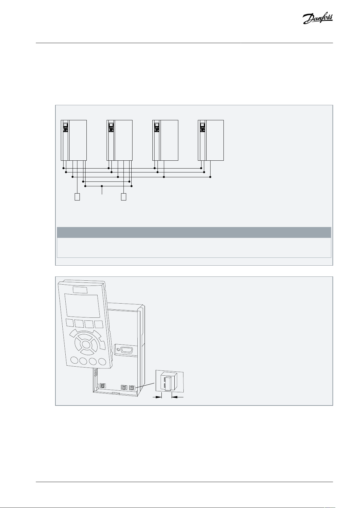
Significant reduced wiring complexity as the drive communication is daisy-chain using the on-board RS485 communication terminals. The communication protocol is Modbus RTU and requires an absolute minimum setup of parameters. The dialog-based Smart
Start makes configuration easy and trouble-free.
The automatic drive detection supports hot-swap providing a rigid system setup against loose connection or cable failure. In case of
master drive failure, the system automatically reallocates the master functionality.
In water distribution systems, it is usually the requirement that the cascade system has a redundant master functionality, this functionality is now an integrated solution in the drives. Multi-Master Cascade comes with improved functionalities and system performance, as the master knows the status and performance of the individual drives and pumps.
Example
The illustration shows a system with 4 AC Drives, where 2 are allocated Master recognized by License Code LXX1. In case of defect
on Master Drive ID 1, the master automatically changes to ID 2 for full functionality until replaced on site. This example is considered
to explain the different phases such as installation, commissioning, and troubleshooting.
Illustration 1: Illustration Example
Application setups supported by Modbus Multi-Master Cascade
Following are the six setups supported by Modbus Multi-Master Cascade
•
Supports only Master Follower cascade.
•
Equal sized pumps.
•
A maximum of 8 pumps in cascade system.
•
A master drive requires a license code (LXX1 or LX11) to unlock the master functionality and Parameter Group 27-*.
•
A minimum of 1 master for Modbus Cascade.
•
A minimum of 2 masters for accomplishing Multi-Master Cascade.
Setup 3 and Setup 4 are not available in Modbus Multi-Master Cascade in software versions 3.91 or older versions. Setups 1 and 2
are assigned for Multi-Master. Flexibility in assigning different setups for different scenarios is limited.
For use of digital cascade without multi-master and available in setup 3 and 4, use parameter 8–30[22] Modbus Cascade Master in
software version 3.40.
N O T I C E
N O T I C E
AB389040992368en-000101 / 130R12296 | Danfoss A/S © 2021.12
•
•
•
•
•
•
VLT® Product
Minimum Software Compatibility Version
VLT® AQUA Drive FC 202
Software version 4.11 and higher on all drives in cascade system.
Control Card Version
Identification of Control Card Version
Production Identification
MKII
White USB
CW18 Y2018 or later.
Scenario
Control
Card
Parameter 15–
43
Action
1
MKII
3.91
Order license code. See 2.3 Ordering Multi-Master Cascade Control Flash software version 4.11 or
newer.
2
MKII
3.80 or
older
Flash software version 4.11 or newer.
Order license code for master drive(s). See 2.3 Ordering Multi-Master Cascade Control.
3
MKI
Order new control card.
Order license Code for master drive(s). See 2.3 Ordering Multi-Master Cascade Control.
Replace old control card with new Mk II control card. Ensure to upgrade to software version
4.11.
Enable license code for master drive(s).
Note: It is not possible to order an MKII control card with pre-initialized license code activated.
Activation must take place on site.
Multi-Master Cascade Control
Introduction to Multi-Master
Application Guide
Cascade Control
2.2 System Requirements and Compatibility
VLT® products and software compatibility for Multi-Master Cacade Control
To enable and effective functioning of Multi-Master Cascade Control, verify the following software compatibility and system-requirements.
Table 1: VLT® Product and Software Compatibility for Multi-Master Cascade Control
Table 2: Control Card Compatibility for Multi-Master Cascade Control
Retrofit existing VLT® AQUA Drive FC 202
Following are the 3 scenarios and actions to retrofit an existing drive.
Table 3: Retrofit Existing VLT® AQUA Drive FC 202
2.2.1 Identifying Control Card
2.3 Ordering Multi-Master Cascade Control
Modbus multi-master is enabled with license codes. The license codes can be installed from the factory or retrofit to an existing
VLT® AQUA Drive FC 202.
2.3.1 Ordering from Factory
Procedure
1.
Select the license code character [12]. For example, LXX1 replaces SXXX.
2.3.2 Ordering Retrofit on Existing VLT® Product
To proceed with creation of unique license code, it is required to obtain the S/N number of each VLT® AQUA Drive FC 202 which is
intended as master. After generating unique license code(s), the list is shared for activating the feature in the drives.
Procedure
1.
Order a retrofit license key via local Danfoss sales office contact.
AB389040992368en-000101 / 130R1229 | 7Danfoss A/S © 2021.12
Parameter Number
Factory delivered license code
Retrofit license code
15–44 Ordered Typecode String
LXX1
SXXX
15-45 Actual Typecode String
LXX1
LXX1
50-00 License Installed
Cascade 2.0
Cascade 2.0
Multi-Master Cascade Control
Application Guide
2.
Obtain the S/N number of each VLT® AQUA Drive FC 202 which is intended as master. Send the S/N information to the local
Danfoss contact.
S/N can be obtained in different ways:
•
On invoice with specific drive
•
Value is identified in parameter 15-51 using LCP or MCT-10
•
Product label
3.
Enter the license key in parameter 50-01.
After the drive accepts the license key, parameter 50-01 displays 0000-0000-0000-0000.
Power cycle the drive.
4.
2.3.3 Identifying License Key for Cascade Control
Procedure
To identify license key for cascade control, verify the typecode using the following parameters.
1.
Introduction to Multi-Master
Cascade Control
The ordered type code string is not changed when activating a retrofit license in the drive.
2.4 Loading new software to AC drives
Procedure
1.
Create a back-up of the parameters.
•
Copy parameters to project in MCT-10.
•
Save project.
2.
Load the software into AC drives.
•
Remove the Modbus Connector (plug 61, 68, 69) before loading the software via the USB port.
•
After connecting the USB port, right-click on the USB 1 in the software tray on the PC.
•
Click Drive Software Upgrader. (requires Service Level 1 access). Contact Danfoss if needed.
•
Locate the required file and click Start Upgrade.
3.
After uploading the software to the drive, perform the following:
•
Connect Modbus Connector (plug 6, 68, 69) again.
•
Write parameters from the project back to AC drive.
•
Power cycle AC drive.
N O T I C E
AB389040992368en-000101 / 130R12298 | Danfoss A/S © 2021.12
68 696120
1 2 3 4
18 68 68 6869 69 69
6161
20 18
LXX1 LXX1
Pressure
transmitter
Pressure
transmitter
Start signal
e30bi494.10
e30bf146.10
BUS TER.
OFF-ON
A53 A54
U- I U- I
1
2
N O
1
2
N O
1
2
N O
1
2
N O
Multi-Master Cascade Control
Installing Modbus Multi-Master
Application Guide
3 Installing Modbus Multi-Master Cascade Control
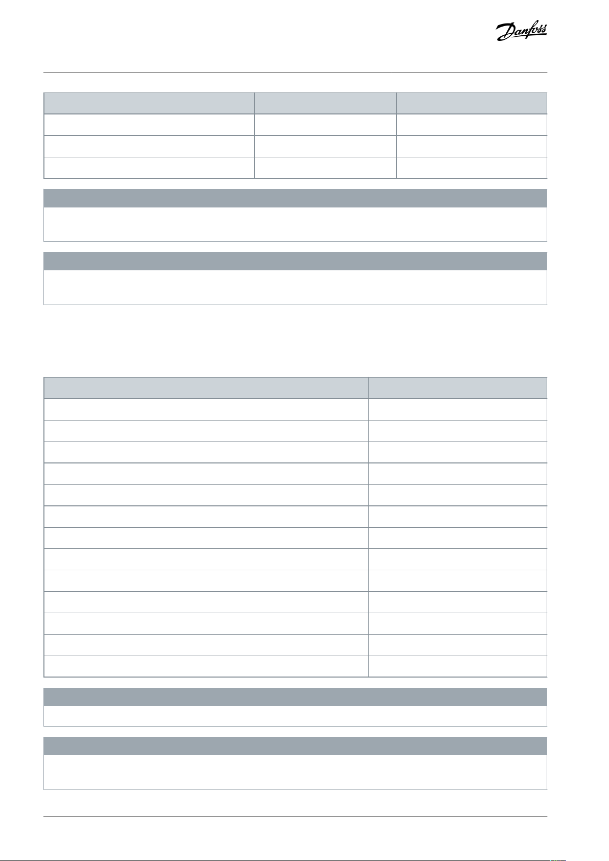
3.1 Wiring the Daisy Chain Module
Ensure to install the drive using the instructions provided in VLT® AQUA Drive FC 202 Operating Guide.
Procedure
1.
Wire Modbus in Daisy Chain Terminal 68 and Terminal 69, and Terminal 61.
Cascade Control
Illustration 2: Wiring Daisy Chain Modbus
N O T I C E
Each assigned master requires a start signal and feedback. For example, pressure transmitter and PID must be set up
and tuned.
2.
Terminate first and last drive by S801 ON.
AB389040992368en-000101 / 130R1229 | 9Danfoss A/S © 2021.12

1
1 2 3 4
2 3 4
Line supply
LXX1 LXX1
68 69 68 68 6869 69 69
100% 100% 100% 100%
e30bi492.10
Parameter 8–31
SW
Priority
Set the value as 1
LXX1
Primary Master (setup 1 and 2)
Set the value as 2
LXX1
Back-up Master (setup 1 and 2)
Set the value as 3
SXXX
Follower (setup 1)
Set the value as 4
SXXX
Follower (setup 1)
Multi-Master Cascade Control
Multi-Master Cascade Control
Application Guide
Parameter Setup
4 Multi-Master Cascade Control Parameter Setup
4.1 Multi-Master Cascade Control Parameter Setup
A typical multi-master cascade parameter setup has the following:
•
Parameter 8–30[23] is set as Modbus Multi-Master on master drives.
•
A minimum of 2 master drives is required to obtain multi-master functionality. A maximum of 8 masters are allowed.
•
For masters, use 2 setups and must be configured in setup 1 and setup 2.
•
For followers, use 1 setup.
•
Ensure parameter 8–32 Baud Rate is identical in all drives (masters and followers).
4.2 Assigning Correct Addresses for Modbus Multi-Master Cascade Control System
If there are multiple masters the consisting of primary master and backup masters, the master status is determined by parameter 8–
31 Address, where the lowest assigned is Primary Master. All back-up masters power up as assigned follower as they do not have the
lowest address.
For example, Drive ID 1 is primary master as the assigned address 1 is the lowest. The system setup is shown in the figure.
Illustration 3: System Setup Example
For the system setup shown in the figure, the parameter setup and priority is as follows:
Considerations when assigning parameter 8–31:
•
The drive ID must be in the order from 1–8.
•
Drive IDs should be sequential. This means that a setup from 1, 3, 4, 5 is not allowed as 2 is missing.
•
Masters must be assigned lowest IDs. For example, when there are 4 master drives, these drives are assigned IDs from 1–4.
•
Follower drives must be assigned IDs following the master node addresses. Consider 4 masters and 4 followers, the followers
must be assigned 5,6,7,8.
4.3 Maintenance and Replacement Scenario
If an assigned master is failing or being powered off due to maintenance, the next lowest address is assigned to the master drive
automatically.
If a drive with lower address is reinserted into the system, the lowest address reinserts into the system as a follower. Assignment of
master functionality to the lowest address in the system happens automatically.
AB389040992368en-000101 / 130R122910 | Danfoss A/S © 2021.12

Parameter
Set-up 1 (Master Mode)
Set-up 2 (Follower Mode)
Parameter 0-02 Motor Speed Unit
[1] Hz**
[1] Hz**
Parameter 0-10 Active Setup
[9] Multi Set-up
[9] Multi Set-up
Parameter 0-12 This Set-up Linked to
[2] Set-up*
[1] Set-up 1*
Parameter 0-21 Display Line 1.2 Small
[1652] Feedback[Unit]**
[0] None**
Parameter 0-23 Display Line 2 Large
[2794] Cascade System Status
[39] Display Text 3
Parameter 0-24 Display Line 3 Large
[2793] Cascade Option Status
[38] Display Text 2
Parameter 0-38 Display Text 2
Follower **
Follower **
Parameter 0-39 Display Text 3
Backup Master **
Backup Master **
Parameter 1-00 Configuration mode
[3] Closed Loop *
[0] Open Loop*
Parameter 3-03 Maximum Reference
[100] Application Specific**
= Par. 4-13 RPM / Par. 4-14 Hz*
Parameter 3-15 Reference 1 Source
[0] No function *
[0] No function *
Parameter 3-41 Ramp 1 Ramp Up Time
A
A
Parameter 3-42 Ramp 1 Ramp Down Time
B
B
Parameter 4-12 Motor Speed Low Limit [Hz]
C
C
Parameter 4-14 Motor Speed High Limit [Hz]
DDParameter 5-10 Terminal 18 Digital Input
[8] Start*
[0] No Operation *
Parameter 6-01 Live Zero Timeout Function
[30] Warning only *
[30] Warning only *
Parameter 6-22 Terminal 54 Low Current
Application specific
Ignore
Parameter 6-23 Terminal 54 High Current
Application specific
Ignore
Parameter 6-24 Term 54 Low Ref. / Feedb. Val
Application specific
Ignore
Parameter 6-25 Term 54 High Ref. / Feedb. val
Application specific
Ignore
Parameter 8-01 Control Site
[0] Digital and ctrl.word **
[2] Control word only
Parameter 8-02 Control Source
[0] None or [3] Option A *
[1] FC Port *
Parameter 8-04 Control Timeout Function
Application specific
[0] Off *
Parameter 8-30 Protocol
[23] Modbus Multi Master *
[23] Modbus Multi Master *
Parameter 8-31 Address
1-x
1-x
Multi-Master Cascade Control
Multi-Master Cascade Control
Application Guide
Parameter Setup
4.4 Parameter Setup for Master Drive(s) – Basic Setup
Parameters for the master drive must be configured in setup 1 and setup 2.
•
Setup 1 (Master Mode): The drive receives commands from digital input or A-option. Speed reference is obtained from PID.
•
Setup 2 (Follower Mode): The drive receives commands from the assigned master drive, in the system, ignoring digital and
analogue input and A options input. Speed reference in set-up must be scaled equal to the master drive in set-up 1.
The following table describes the basic setup for master drives. In the table, * indicates mandatory settings and ** indicates recommended settings.
Table 4: Basic setup for master drives
AB389040992368en-000101 / 130R1229 | 11Danfoss A/S © 2021.12
Parameter
Set-up 1 (Master Mode)
Set-up 2 (Follower Mode)
Parameter 20-00 Feedback 1 Source
[2] Analog Input 54 *
Ignore
Parameter 27-10 Cascade Controller
[1] Master/Follower *
[1] Master/Follower *
Parameter 27-11 Number Of Drives
E (max 8)
E (max 8)
Parameter
Setup Follower
Parameter 0-02 Motor Speed Unit
[1] Hz **
Parameter 0–24 Display Line 3 Large
[38] Display Text 2 **
Parameter 0–38 Display Text 2
Follower **
Parameter 1-00 Configuration mode
[0] Open Loop *
Parameter 3-03 Maximum reference
= Par. 4–12 (Hz) *
Parameter 3–15 Reference 1 Source
[0] No function *
Parameter 4–14 Motor Speed High Limit [Hz]
D *
Parameter 8-01 Control Site
[2] Control word only**
Parameter 8-02 Control Source
[1] FC Port *
Parameter 8-03 Control Timeout
15.00 s**
Parameter 8-04 Control Timeout Function
[2] Stop**
Parameter 8–30 Protocol
[2] Modbus RTU *
Parameter 8–31 Address
2-x *
Multi-Master Cascade Control
Multi-Master Cascade Control
Application Guide
Parameter Setup
N O T I C E
Ensure the values in parameter numbers 3–41 Ramp 1 Ramp Up Time, 3–42 Ramp 1 Ramp Down Time, 4–12 Motor Speed Low Limit
[Hz], 4–14 Motor Speed High Limit [Hz], 8–31 Address, 27–11 Number Of Drives are identical in setup 1 and setup 2.
N O T I C E
Ensure that parameter 8-04 Control Word Timeout Function is only configured when parameter 8-02 Control Word Source is set as A
option. If parameter 8-02 Control Word Source is set as 0, do not set any values in parameter 8-04 Control Word Timeout Function.
4.5 Parameter Setup for Followers (Basic Setup)
A follower utilizes set-up 1 only and follows the commands send by the primary master. The following table details the basic setup
for followers.
Table 5: Recommended Settings for Follower Setup
Ensure parameter 8-01 Control Site is not set to [1] Digital only.
A control timeout is recommended when the master drive is not active. On setting parameter 8-04 Control Word Timeout to [2]
Stop, the follower drive resumes when a master drive is reactivated.
N O T I C E
N O T I C E
AB389040992368en-000101 / 130R122912 | Danfoss A/S © 2021.12

Multi-Master Cascade Control
Application Guide
4.6 Copy settings
Typically, it is recommended to copy settings to all drives in the system.
Copy Settings to all drives in the system
Copying settings is achieved by using the parameter 0–50 LCP Copy [1] All to LCP or MCT10.
Copying from (Master to Master) or (Follower to Follower)
Ensure to change the parameter 8–31 Address so that no drives should have the same address.
Copying from Master to Follower
It is not recommended to copy settings from master to follower.
Multi-Master Cascade Control
Parameter Setup
AB389040992368en-000101 / 130R1229 | 13Danfoss A/S © 2021.12

1
1 2 3 4
2 3 4
Line supply
LXX1 LXX1
68 69 68 68 6869 69 69
100% 100% 100% 100%
e30bi492.10
Parameter
Setup 1 (Master Mode)
Example Setting
Setup 2 (Follower Mode)
Parameter 27-32.0 Stage On Speed [Hz]
Ignore
48.5
Ignore
Parameter 27-32.1 Stage On Speed [Hz]
Pump 2 staging speed
48.5
Ignore
Parameter 27-32.2 Stage On Speed [Hz]
Pump 3 staging speed
48.5
Ignore
Parameter 27-32.3 Stage On Speed [Hz]
Pump 4 staging speed
48.5
Ignore
Parameter 27-32.4 Stage On Speed [Hz]
Ignore
48.5
Ignore
Parameter 27-32.5 Stage On Speed [Hz]
Ignore
48.5
Ignore
Parameter 27-32.6 Stage On Speed [Hz]
Ignore
48.5
Ignore
Parameter 27-32.7 Stage On Speed [Hz]
Ignore
48.5
Ignore
Parameter 27-32.8 Stage On Speed [Hz]
Ignore
48.5
Ignore
Parameter 27-32.9 Stage On Speed [Hz]
Ignore
48.5
Ignore
Parameter 27-32.10 Stage On Speed [Hz]
Ignore
48.5
Ignore
Parameter
Setup 1 (Master Mode)
Example Setting
Setup 2 (Follower Mode)
Parameter 27-34.0 Stage Off Speed [Hz]
Ignore
0
Ignore
Parameter 27-34. Stage Off Speed [Hz]
Pump 1 off**
30.5
Ignore
Multi-Master Cascade Control
Application Guide
Staging Parameter Setup
5 Staging Parameter Setup
5.1 Staging Parameter Setup
Consider the example with 4 drives in a setup. Ensure that staging parameters are set for assigned masters in setup 1. Setup 2 can
be disregarded. Followers do not require configuration of staging parameters. Staging speeds and de-staging speeds are application specific.
In the following sections, recommendation settings for the stage-on speed, stage-off speed, and general staging parameters.
5.2 Stage-On Speed
Table 6: Stage-On Speed Parameters
The highest index speed in parameter 27–32.X must be set to motor speed high limit in parameter 4–13 Motor Speed High Limit [RPM]
or parameter 4–14 Motor Speed High Limit [Hz].
5.3 Stage-Off Speed
Table 7: Stage-off Speed Parameters
AB389040992368en-000101 / 130R122914 | Danfoss A/S © 2021.12
Parameter
Setup 1 (Master Mode)
Example Setting
Setup 2 (Follower Mode)
Parameter 27-34.2 Stage Off Speed [Hz]
Pump 2 de-staging
32
Ignore
Parameter 27-34.3 Stage Off Speed [Hz]
Pump 3 de-staging
34
Ignore
Parameter 27-34.4 Stage Off Speed [Hz]
Pump 4 de-staging
36
Ignore
Parameter 27-34.5 Stage Off Speed [Hz]
Ignore
37.5
Ignore
Parameter 27-34.6 Stage Off Speed [Hz]
Ignore
39.2
Ignore
Parameter 27-34.7 Stage Off Speed [Hz]
Ignore
40.4
Ignore
Parameter 27-34.8 Stage Off Speed [Hz]
Ignore
41.3
Ignore
Parameter 27-34.9 Stage Off Speed [Hz]
Ignore
42
Ignore
Parameter 27-34.10 Stage Off Speed [Hz]
Ignore
42.5
Ignore
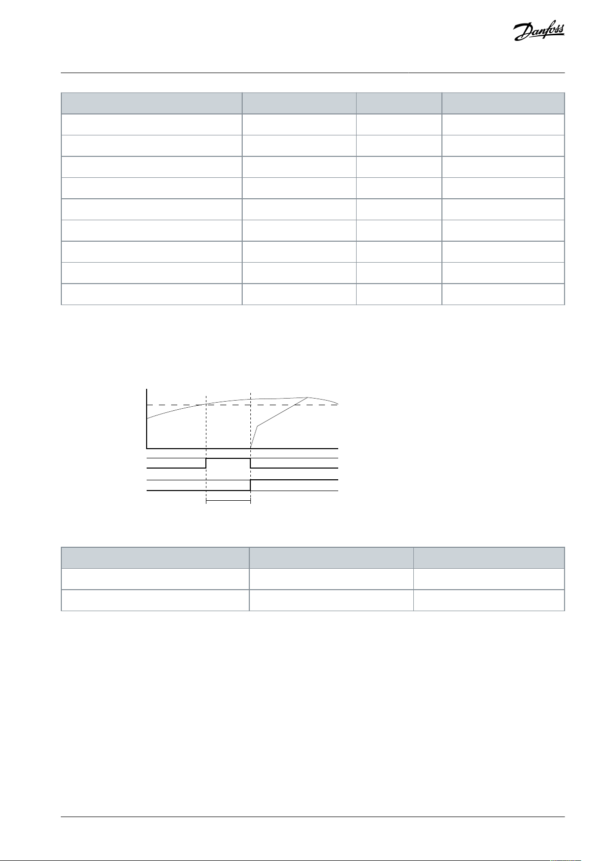
15 Sec
Par. 27-32.X
Stage On Speed [Hz]
ONPar. 27-23
Staging Delay (sec)
OFF
Par. 27-32.1
DI Terminal 18 [start signal]
Frequency
Pump 1 speed
Pump 2 speed
Time
e30bi491.10
Parameter ID
Setup 1 (Master Mode)
Setup 2 (Follower Mode)
Parameter 27-23 Staging Delay
15 seconds (recommended)
Ignore
Parameter 27-24 Destaging Delay
15 seconds (recommended)
Ignore
Multi-Master Cascade Control
Application Guide
Staging Parameter Setup
** Lowest index speed in parameter 27-34.1 must be equal or greater than motor speed low limit specified in parameter 4-11 Motor
Speed Low Limit [RPM] or parameter 4-12 Motor Speed Low Limit [Hz].
5.4 General Staging Parameters
This section provides an overview of the parameters for general staging.
Illustration 4: General Staging Parameters
Table 8: General Staging Parameters
AB389040992368en-000101 / 130R1229 | 15Danfoss A/S © 2021.12

Parameter
Setup 1 (Master Mode)
Setup 2 (Follower Mode)
Parameter 27–21 Override Limit
10%
Ignore
Parameter 20-21Setpoint 1
Application specific [80]
Ignore
Parameter
Setup 1 (Master Mode)
Setup 2 (Follower Mode)
Parameter 3-03 Maximum Reference
100
= Parameter 4-14 Motor Speed High Limit [Hz] (D)
Parameter 27–21 Override Limit
10%
Ignore
Parameter 20–2 Setpoint 1
80
Ignore
Multi-Master Cascade Control
Application Guide
Sleep Mode Parameter Overview
6 Sleep Mode Parameter Overview
6.1 Sleep Mode Parameter Setup
When the last pump which is operating drops below parameter 27–34.1, sleep mode is activated. The de-stage speed for the duration set in parameter 27–24 De-staging Delay.
6.2 Entering Sleep Mode
Sleep mode occurs when the actual speed is less than the value configured in parameter 27–34.1 Stage Off Speed for the time in
seconds configured in parameter 27–24 De-staging Delay.
To enable sleep mode, make sure the parameter 27–34.1 Stage Off Speed is higher than parameter 4–11 Motor Speed Low Limit [RPM]
or parameter 4–12 Motor Speed Low Limit [Hz].
If the value in parameter 27–34.01 is equal or less than the value specified in parameter 4–11 Motor Speed Low Limit [RPM] or parame-
ter 4–12 Motor Speed Low Limit [Hz], the system continues to operate at minimum speed. For example, if setting parameter 4–11
Motor Speed Low Limit [RPM] or parameter 4–12 Motor Speed Low Limit [Hz] is set to 0, sleep mode is disabled and continues to oper-
ate at minimum speed.
6.3 Activating Drives from Sleep Mode
Table 9: Recommended Parameter Settings
Following is an example of activating drives from sleep mode.
Table 10: Example of Recommended Parameters
Multi-Master Control activates during sleep mode when parameter 27–21 Override Limit is reached. Override Limit is a % of parameter 3-03 Maximum Reference.
How to calculate:
Drive start < Setpoint in parameter 20–21 Setpoint 1 – (Parameter 27–21 Override Limit x Parameter 3-03 Maximum Reference) )
Drive start < 80 – (10% x 100) = 70
AB389040992368en-000101 / 130R122916 | Danfoss A/S © 2021.12

1
1 2 3 4
2 3 4
Line supply
LXX1 LXX1
68 69 68 68 6869 69 69
100% 100% 100% 100%
e30bi492.10
Frequency
Pump 4 Pump 2 Pump 3
Time
15 Sec 15 Sec
OFF
DI Terminal 18 [start signal]
Par. 27-32.2
Par. 27-32.1
OFF
ON
Par. 27-32.X
Stage On Speed [Hz]
Par. 4-12
Motor Speed Low Limit [Hz]
Staging Delay (sec)
Par. 27-23
e30bi490.10
Multi-Master Cascade Control
Application Guide
Cascading Operation and Settings
7 Cascading Operation and Settings
7.1 Cascading Operation
Consider the scenario when the system is activated with Start signal.
Illustration 5: Scenario Illustration
Start signal is started via Digital Input on Terminal 18.
Pump 4 is activated first as it has least running hours. If the frequency rises above parameter 27-32.X during the duration specified in
parameter 27-23 , the subsequent pump with the second least running hours begins. In this case, pump 2 is staged. If the frequency
is still above parameter 27-32.X for the duration specified in parameter 27-23, the pump with third least running hours begins. In this
case, pump 3 is staged on. This continues as the last pump is staged on.
Illustration 6: Cascading Operation
On the contrary, when the frequency is below parameter 27-34.X stage off for duration of parameter 27-24 De-stage Delay, the drive
with the highest running hours stops. This continues until 1 pump is running at a frequency below the value specified in Parameter
27-34.1 Stage Off, and higher than parameter 4-12 Motor Speed Low Limit for the duration specified in parameter 27-24 De-stage Delay.
The last drive stops and the system goes into sleep mode
AB389040992368en-000101 / 130R1229 | 17Danfoss A/S © 2021.12

LCP
view
and
notes
For 3 drives
For 8 drives
LCP
view
e30bj394.10
e30bj395.10
Notes
Off is the current state of the unit viewed.
Notice: Off is viewed in 2 places. The meaning for both is the
same.
Colon is used in-between, for example, M:o
Off is the current state of the unit viewed.
Notice: Off is only viewed in 1 place due to lack of space.
No colon is used, for example, Mo.
Drive
Options
Description
Master (M)
o
The master drive is online but idle (not running), Mo indicates that the master drive is online but idle.
Follower (F)
D
The follower drive is online and running. FD indicates that the follower drive is online and running.
Follower (F)
x
The drive is not reachable by network. This is possible when parameter 27–11 is set to 3 and only 2
drives are connected.
Fx indicates that the follower drive cannot be reached by network.
MXInterlock, trip, Drive not ready, Drive coast, Drive trip lock status of the master drive.
MX indicates Master interlock.
Option
Description
Off
System is stopped
Running
System is running with 1 or more pump.
Multi-Master Cascade Control
Application Guide
Cascading Operation and Settings
N O T I C E
If the parameter 4-12 Motor Speed Low Limit is higher than the value specified in parameter 27-31.1 Stage Off Speed, the last drive
continues to operate in minimum speed until the stop signal is started.
7.2 Local Control Panel (LCP) Readings
The following table describes LCP readings for the parameter settings.
•
Parameter 0–23 Display Line 2 Large as [2794] Cascade System Status
•
Parameter 0–24 Display Line 3 Large as [2793] Cascade Option Status
To set the number of drives, go to parameter 27–11 Number of drives and set as required.
Table 11: LCP view
Table 12: Options and Description for Display Large [2794] as Cascade System Status
Table 13: Options and Description for Display Large as [2793] Cascade Option Status
AB389040992368en-000101 / 130R122918 | Danfoss A/S © 2021.12

Option
Description
Stg
A pump is staged in.
dstg
A pump is de-staged.
Alt
Alternation is occurring.
Multi-Master Cascade Control
Application Guide
Cascading Operation and Settings
AB389040992368en-000101 / 130R1229 | 19Danfoss A/S © 2021.12

1
1 2 3 4
2 3 4
Line supply
!
LXX1 LXX1
68 69 68 68 6869 69 69
e30bi486.10
1
1 2 3 4
2 3 4
Line supply
!
LXX1 LXX1
68 69 68 68 6869 69 69
e30bi487.10
Multi-Master Cascade Control
Application Guide
8 Maintenance Scenarios
8.1 Service on Primary Master (Address 1)
Consider the scenario to stop only the primary master without stopping the drive.
N O T I C E
It is recommended to use DI (Digital Input)
Maintenance Scenarios
It is recommended to use DI (Digital Input) [130] Pump 1 interlock.
An example of actions to stop the master drive and keep the system running are as follows:
•
Wire DI 33
•
Program parameter 5-15 as [130] Pump 1 interlock
The following actions will stop the complete system:
•
[Hand On] or [Off] mode on LCP keypad will stop all follower drives.
•
Using DI for external interlock parameter 5-* [7]. External interlock stops the complete system.
8.2 Service on Backup Master running as a Follower
Consider the scenario to service on backup master running as a follower.
Illustration 7: Service on Backup Master drive which runs as a Follower Drive
[Off] mode on Drive 2 LCP keypad, stops pump 2.
It is recommended to use pump interlock DI using [131] Pump 2 interlock on Master Drive, as drive 2 is the backup master and
potentially becomes the master drive in cases of primary master drive break-down. The wiring should be to both primary and secondary master drive.
See wiring example.
AB389040992368en-000101 / 130R122920 | Danfoss A/S © 2021.12

68 696120
1
19
27
29
32
2 3 4
18 68 68 6869 69 69
6161
20 18
LXX1 LXX1
Pump interlock 1
Pump interlock 2
Pump interlock 3
Pump interlock 4
Pressure
transmitter
Pressure
transmitter
Start signal
e30bi489.10
1
1 2 3 4
2 3 4
Line supply
!
LXX1 LXX1
68 69 68 68 6869 69 69
e30bi488.10
Multi-Master Cascade Control
Application Guide
Maintenance Scenarios
Illustration 8: Wiring Example
8.3 Service on Follower
Consider the scenario when the follower drive on pump 3 fails. Any actions performed affects only the specific drive.
Illustration 9: Service on Follower Drive
AB389040992368en-000101 / 130R1229 | 21Danfoss A/S © 2021.12

•
•
•
•
•
•
•
•
•
•
1
1 2 3 4
2 3 4
Line supply
!
LXX1 LXX1
68 69 68 68 6869 69 69
e30bi486.10
System setup
System Action
Primary
Master (Address 1)
Change the master, when the following occurs on the primary master:
Supply power is turned off.
Control card defect.
Warning, Live Zero error. This is only shown if parameter 6-01 Live Zero Timeout Function is configured to [30]
Warning Only.
The system stops when primary master detects the following:
Alarm 68, Safe Stop Activated.
Alarm 94, End of Curve.
Alarm 92, No Flow Alarm.
Alarm 93, Dry Pump Alarm.
Alarm 60, External Interlock.
Followers are operating, when the primary master stops:
Any other alarm/fault.
LCP status: M:X F:D F:D F:D
Multi-Master Cascade Control
Application Guide
Alarms, Warnings, and Defects
9 Alarms, Warnings, and Defects
9.1 System Setups and Actions to Alarms, Warnings
This section explains behaviors which are triggered by alarms, warnings, and defects. Following are three examples.
LCP status: M:X F:D F:D F:D
Illustration 10: System Setup - Primary Master (Address 1)
Table 14: System Actions
AB389040992368en-000101 / 130R122922 | Danfoss A/S © 2021.12

•
•
•
•
•
1
1 2 3 4
2 3 4
Line supply
!
LXX1 LXX1
68 69 68 68 6869 69 69
e30bi487.10
System setup
System Action
Backup Master (Runs as Followers)
During this alarm, the drive continues to operate.
The LCP status is M:D F:X F:D F:D.
1
1 2 3 4
2 3 4
Line supply
!
LXX1 LXX1
68 69 68 68 6869 69 69
e30bi488.10
System setup
System Action
Follower
The follower stops.
The system continues.
The LCP status is displayed as M:D F:D F:X F:D.
Multi-Master Cascade Control
Application Guide
LCP status: M:D F:X F:D F:D
Illustration 11: System Setup - Backup Master
Table 15: System Actions
Alarms, Warnings, and Defects
LCP status: M:D F:D F:X F:D
Illustration 12: System Setup - Follower Drive
Table 16: System Actions
AB389040992368en-000101 / 130R1229 | 23Danfoss A/S © 2021.12
Time
Final ramp
down time
Check valve
ramp down
time
Normal
ramp
Initial
ramp time
Normal
ramp down
time
Check valve
end speed
Motor speed
low limit
Motor speed
high limit
Speed
e30bj392.10
Power
Frequency
Low speed
High
speed
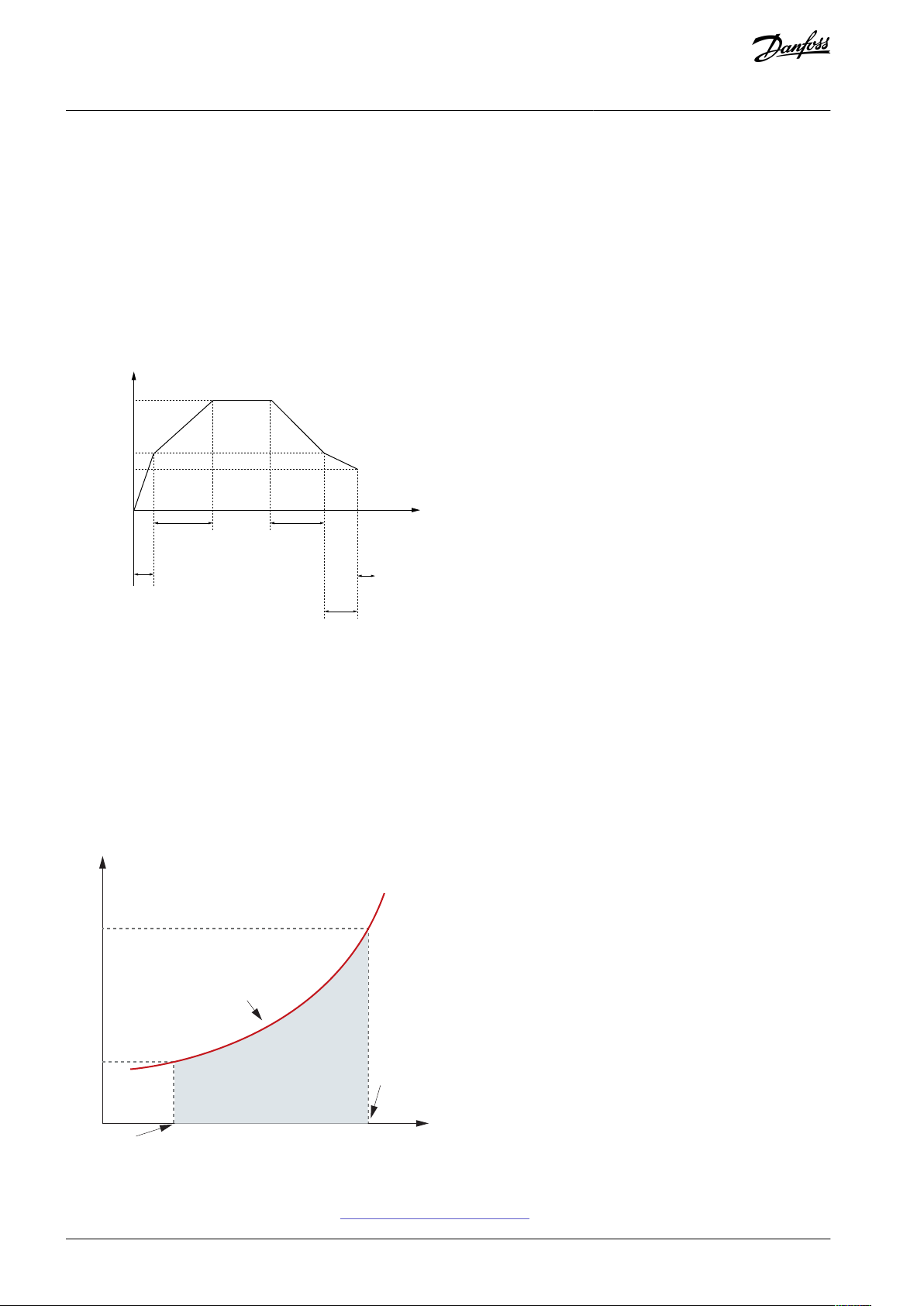
power
Low
speed
power
No/low flow
power curve
High
speed
No/low flow detection
e30bi482.10
No/Low flow detection
Multi-Master Cascade Control
Water Features with Multi-Master
Application Guide
Cascade
10 Water Features with Multi-Master Cascade
10.1 Water Features
This section provides an overview of water related features which are enabled when using the Multi-Master Cascade Control. This
section briefs on the compatibility with the multi-master setup and the parameters to configure to enable the feature..
10.2 Check Valve Ramp
Feature compatible with Multi-Master Setup
Yes, the feature can work with multi-master cascade setup of drives.
How does Check Valve Ramp work?
Illustration 13: Check Valve Ramp
Parameters to configure the feature
•
Parameter 3–85 is application specific.
•
Parameter 3-86/Parameter 3–87 is application specific.
10.3 Sleep Mode
Feature compatibility with Multi-Master Cascade Setup
This feature is supported by the multi-master cascade setup.
How does the feature work?
Illustration 14: Sleep Mode
Parameter to configure the feature:
For more information on how to configure, see 6.1 Sleep Mode Parameter Setup
AB389040992368en-000101 / 130R122924 | Danfoss A/S © 2021.12

Speed
Derag function
activated
Derag off delay:
Par. 29-15
Time
Deragging run time: Par. 29-12
1 cycle
Number of cycles: Par. 29-10
+/- derag
speed:
Par. 29-13
Par. 29-14
0 Hz/RPM
e30bi483.10
Power
Frequency
Low speed
High
speed
power
Low
speed
power
No/low flow
power curve
High
speed
No/low flow detection
e30bi482.10
No/Low flow detection
Multi-Master Cascade Control
Application Guide
10.4 Deragging
Feature compatibility with Multi-Master Control Set up
No, this feature does not work with multi-master control set up of drives.
How does the feature work?
Water Features with Multi-Master
Cascade
Illustration 15: Deragging
10.5 Dry Pump
Feature compatibility with Multi-Master Control Setup
The feature work with conditions on Multi-Master control setup of drives. The feature can be used if primary master drive has priority 1 and all back-up master and follower drives have priority 2 or spare pump which is specified in parameter 27–16.
N O T I C E
This type of setting means that the primary master drive always operates when a demand is available and is not part of normal
runtime balancing to even out the running hours of the pumps.
How does the feature work?
Illustration 16: Dry Pump
AB389040992368en-000101 / 130R1229 | 25Danfoss A/S © 2021.12

Pressure
Pump curve
System curve
Flow
e30bi480.10
Pressure
Flow
Flow
compensation
Constant pressure
operation
Energy saved
e30bi481.10
Multi-Master Cascade Control
Water Features with Multi-Master
Application Guide
Cascade
10.6 End of Curve Detection
Feature Compatibility with Multi Master Cascade Setup
The feature work with conditions on Multi-Master Cascade set up of drives. The feature can be used if primary master drive has
priority 1 and all back-up master and follower drives have priority 2 or spare pump which is specified in parameter 27–16.
N O T I C E
This type of setting means that the primary master drive always operates when a demand is available and is not part of normal
runtime balancing to even out the running hours of the pumps.
How does the feature work?
Illustration 17: End of Curve Detection
10.7 Flow Compensation
Feature Compatibility with Multi Master Cascade Setup
The feature works with Multi-Master Cascade set up of drives.
How does the feature work?
Illustration 18: Flow Compensation
How to configure the feature?
Configure the following parameters:
AB389040992368en-000101 / 130R122926 | Danfoss A/S © 2021.12

Time
Final ramp
down time
Check valve
ramp down
time
Normal
ramp
Initial
ramp time
Normal
ramp down
time
Check valve
end speed
Motor speed
low limit
Motor speed
high limit
Speed
e30bj392.10
Multi-Master Cascade Control
Application Guide
•
Parameter 22–80 as [1] Enabled
•
Parameter 22–87 to application specific settings
•
Parameter 20–21 to application specific settings
10.8 Pipefill
Feature Compatibility with Multi Master Cascade Setup
The feature works with Multi-Master Cascade setup of drives.
How does the feature work?
Water Features with Multi-Master
Cascade
Illustration 19: Pipefill
How to configure the feature?
•
Set parameter 29-01 as [1] Enabled.
•
Use speed or pressure.
See VLT® FC 202 Programming guide for information on parameters.
10.9 Flow Confirmation
Feature Compatibility with Multi-Master Cascade Set up
The feature work with conditions on Multi-Master Cascade set up of drives. Can be used if primary master drive has priority 1 and all
back-up master and follower drives have priority 2 or spare pump which is specified in parameter 27-16
N O T I C E
This type of setting means the primary master drive always operates when a demand is available and isnot part of normal run-
time balancing to even out the running hours of the pumps.
AB389040992368en-000101 / 130R1229 | 27Danfoss A/S © 2021.12

Speed
Start command
Verifying flow
Ext. digital signal
(eg. from valve)
Time
t0 t2<t1
ON
ON
ON
OFF
OFF
OFF
Max.
speed
Min.
speed
e30bj393.10
Multi-Master Cascade Control
Water Features with Multi-Master
Application Guide
Cascade
N O T I C E
Flow confirmation for each pump with flow switch can be enabled in Multi-Master with programming of smart logic control. Con-
tact local sales office for support.
How does the feature work?
Illustration 20: Flow Confirmation
AB389040992368en-000101 / 130R122928 | Danfoss A/S © 2021.12

Multi-Master Cascade Control
Application Guide
Index
A
Application Setups.........................................................................................6
C
Cascading Operation.................................................................................. 17
Control Card Compatibility......................................................................... 7
I
Identify license key.........................................................................................8
Installing Modbus Multi-Master Cascade...............................................9
L
Loading new software.................................................................................. 8
M
Maintenance on backup master............................................................. 20
Maintenance on follower.......................................................................... 21
Maintenance on primary master............................................................ 20
Multi-Master Cascade Control....................................................................6
Index
Multi-Master Cascade Control Parameter Setup.............................. 10
O
Ordering Multi-Master Cascade Control................................................ 7
R
Retrofit existing VLT® AQUA FC 202 Drive............................................. 7
S
Sleep mode parameter...............................................................................16
Software Compatibility.................................................................................7
Staging Parameter Setup.......................................................................... 14
T
Troubleshooting...........................................................................................22
W
Water Features with Multi-Master Cascade Control........................24
AB389040992368en-000101/130R1229 | 29Danfoss A/S © 2021.12

Danfoss A/S
Ulsnaes 1
DK-6300 Graasten
vlt-drives.danfoss.com
Danfoss can accept no responsibility for possible errors in catalogs, brochures, and other printed material. Danfoss reserves the right to alter its products without notice. This
also applies to products already on order provided that such alterations can be made without subsequential changes being necessary in specifications already agreed. All
trademarks in this material are property of the respective companies. Danfoss and the Danfoss logotype are trademarks of Danfoss A/S. All rights reserved.
*130R1229*
Danfoss A/S © 2021.12
AB389040992368en-000101 / 130R1229
*M0034201*
 Loading...